
FM/AM
Cassette
Car Stereo
Sony Corporation 2001
Installation/Connections
Instalación/Conexiones
ƒw‚¸¡ ‰u‚ ⁄§‡s–
XR-CA320X
XR-CA320
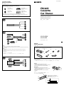
Parts list
Lista de componentes
„s¥ ⁄@˜ “
1
2
5
3
4
× 4
67
The numbers in the list are keyed to those in the instructions.
Los números de la lista corresponden a los de las instrucciones.
„ˇ¥ …˘ƒr»P»¡'œfi ⁄⁄“”…˘ƒr‹O⁄@›P“”¡C
The release key 6 is used for dismounting the unit. See the operating instructions manual for details.
La llave de liberación 6 se utiliza para desmontar la unidad. Con respecto a los detalles, consulte el
manual de instrucciones.
›Y›n§ ¥» ¥ 'T'w⁄§‡B' ¤ł⁄U¤ fi ¡A‰—¤ˇ¥˛ˆP¶}¥˛“”˘_ ˝ 6¡C‚ † ‰—‹ ¤ˇ¥˛»¡'œfi ¡C
Connection example
Ejemplo de conexiones
‰u‚ ‡s– „ˇ¤
Equipment used in illustrations (not supplied)
Equipo utilizado en las ilustraciones (no suministrado)
„ˇ⁄⁄¤ˇ¥˛“”‡]‡˘¡] L“ –a¡^
For connecting two or more changers, the source selector XA-C30 (optional) is necessary.
Cuando desee conectar dos o más cambiadores, necesitará un selector de fuente XA-C30 (opcional).
›Y›n‡s– 2 »O'˛ 2 »O¥H⁄W·«”— fi ¡A«K¶•¤ˇ¥˛› •‰¿ „ XA-C30¡]¿ `˚¥ ¡^¡C
Power amplifier
Amplificador de potencia
¥\†v'æ⁄j „
Front speakers
Altavoces delanteros
«e·›`n „
Rear speakers
Altavoces traseros
«Æ·›`n „
CD/MD changer
Cambiador de CD/MD
CD/MD ·«”—
A
B
BUS CONTROL IN
BUS AUDIO IN
BUS AUDIO IN
BUS CONTROL IN
Source selector
Selector de fuente
› •‰¿ „
C
Notes
• Be sure to connect the earth cord before connecting the amplifier.
• If you connect an optional power amplifier and do not use the built-in amplifier, the beep sound will
be deactivated.
Notas
• Asegúrese de conectar primero el cable de puesta a masa antes de realizar la conexión al
amplificador.
• Si conecta un amplificador de potencia opcional y no utiliza el incorporado, los pitidos se
desactivarán.
ø
•
¨¥†ƒb– 'æ⁄j „⁄§«e‡s– ƒa‰u
¡C
•
ƒp“G–z‡s– ⁄F¿ `˚¥ “”¥\†v'æ⁄j „ƒ ⁄£¤ˇ¥˛⁄”‚¸“”'æ⁄j „¡A–N L„˚`n¥\fl
¡C
AUDIO OUT
Cautions
•Cautionary notice for handling the bracket 1.
Handle the bracket carefully to avoid injuring your fingers.
•Remove the protection collar 5 before installing.
Precauciones
•Advertencia sobre la manipulación del soporte 1.
Tenga mucho cuidado al manipular el soporte para evitar
posibles lesiones en los dedos.
•Retire el collar de protección 5 antes de realizar la
instalación.
“‘•N
•† ˚‚¸¤ł⁄ ‹[ 1 fi ¡A‰—flS§O“‘•N§O¶¸¤⁄«¡C
•ƒw‚¸«e¡A¥ –N«O¯@fi ‹[ 5 ¤œ¥X¡C
Release the catch lock as illustrated.
Suelte el enganche como se muestra en la
ilustración.
ƒp„ˇ' ¥ ¡A† ¶}´Œ” •fƒ'¡C
5
3-225-234-31 (1)
1

182 mm
53 mm
Installation Instalación
ƒw‚¸
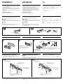
Precautions
•Choose the installation location carefully so that the unit will not
interfere with normal driving.
•Avoid installing the unit in areas subject to dust, dirt, excessive
vibration, or high temperatures, such as in direct sunlight or near
heater ducts.
•Use only the supplied mounting hardware for a safe and secure
installation.
Mounting angle adjustment
Adjust the mounting angle to less than 20°.
How to detach and attach the front panel
Before installing the unit, detach the front panel.
A To detach
Before detaching the front panel, be sure to press (OFF). Press
(RELEASE), then slide the front panel a little to the left, and pull it off
towards you.
B To attach
Attach part A of the front panel to part B of the unit as illustrated
and push the left side into position until it clicks.
Precauciones
•Elija cuidadosamente el lugar de montaje de forma que la unidad
no interfiera las funciones normales de conducción.
•Evite instalar la unidad donde pueda quedar sometida a altas
temperaturas, como a la luz solar directa o al aire caliente de
calefacción, o a polvo, suciedad, o vibraciones excesivas.
•Para realizar una instalación segura y firme, utilice solamente la
ferretería de montaje suministrada.
Ajuste del ángulo de montaje
Ajuste el ángulo de montaje a menos de 20°.
Forma de extraer e instalar el panel frontal
Antes de instalar la unidad, extraiga el panel frontal.
A Para extraerlo
Antes de extraer el panel frontal, asegúrese de presionar (OFF).
Presione (RELEASE), deslice el panel ligeramente hacia la izquierda
y tire de él hacia fuera.
B Para instalarlo
Coloque el orificio A del panel frontal en el eje B de la unidad,
como se muestra en la ilustración, y después presione la parte
izquierda hasta que encaje.
¤ˇ¥˛«e¶•“‘•N
•¥» ‰—'æƒb⁄£§«ˆ“¥q r p⁄§‡B¡C
•` §K–N¥» 'æƒb “•¯⁄§‡B¡Aƒp¶§¥œ“‰– • fig¡B•xfi «e¡B'˛ƒ
ƒh¡B¯…¶ˆ¡A¥H⁄˛•¥' ¤ _ ˚ ¥ƒa⁄Ł¡C
•‹ ⁄Fƒw¥ ⁄˛¥i a“”ƒw‚¸ _¤£¡A››¤ˇ¥˛“ –a“”‡¡¥ ¡C
ƒw‚¸¤⁄« ⁄§‰ ª
‰—ƒb 20 « ¥H⁄”‰ ªƒw‚¸¤⁄« ¡C
ƒpƒ ' ¤ł'M‚¸ t«e“O
ƒw‚¸¥» ⁄§«e¡A‰—¥ ' ¤ł«e“O¡C
A '¤ł
' ¤ł«e“O⁄§«e¡A ¨¥†« ⁄U (OFF) ` ¡C M«Æ¡A« ⁄U (RELEASE) `¡A
–N«e“O y•LƒV¥“ˆ •˘ ˚¡A·´–zƒ ⁄v“”⁄ŁƒV' ¥X¡C
B ‚¸ t
ƒp„ˇ' ¥ ¡A–N«e“O“” A ‡B„ •˙¥» “” B ‡B¡A M«Æ–N¥“ …– ⁄J“‰ƒ
¯¥¤ ‡ ‡ `n¡C
A
B
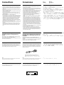
Installation in the dashboard
Instalación en el salpicadero ƒw‚¸ƒb» ¿ “O‚
123
1
Bend these claws outward for a tight
fit, if necessary.
Si es necesario, doble estas uñas hacia
fuera para que encaje firmemente.
›Yƒ‡¥†›n¡A«h¥i¯sƒ–‡o¤˙¥d⁄ ¡C
5
Dashboard
Salpicadero
»¿“O
Fire wall
Panel cortafuegos
¤⁄ı
2
3
1
4
max. size M5 × 8 mm
Tamaño máx.: M5 × 8mm
‡ ⁄j⁄ ⁄o M5¡ 8 mm
Mounting the unit in a Japanese car
You may not be able to install this unit in some makes of Japanese
cars. In such a case, consult your Sony dealer.
TOYOTA NISSAN
to dashboard/centre console
al salpicadero/consola central
ƒ » ¿ “O¢A⁄⁄¥¡––¤ ‰c
Existing parts supplied to your car
Piezas existentes suministradas con su
automóvil
“ –a' ¤T¤fi“”‡¡¥
Bracket
Soporte
ƒ«‹[
to dashboard/centre console
al salpicadero/consola central
ƒ » ¿ “O¡ ⁄⁄¥¡––¤ ‰c
Bracket
Soporte
ƒ«‹[
4 max.size M5 × 8 mm
Tamaño máx.: M5 × 8mm
‡ ⁄j⁄ ⁄oM5 ¡ 8 mm
Note
To prevent malfunction, install only with the supplied screws 4.
Existing parts supplied to your car
Piezas existentes suministradas con su
automóvil
“ –a' ¤T¤fi“”‡¡¥
4 max. size M5 × 8 mm
Tamaño máx.: M5 × 8mm
‡ ⁄j⁄ ⁄o M5¡ 8 mm
4 max. size M5 × 8 mm
Tamaño máx.: M5 × 8mm
‡ ⁄j⁄ ⁄o M5¡ 8 mm
Montaje de la unidad en un automóvil
japonés
Es posible que no pueda instalar esta unidad en algunos automóviles
japoneses. En tal caso, consulte a su proveedor Sony.
–N¥» ƒw‚¸' ⁄Ø¥»†£¤T¤fi‚
ƒ‡“”⁄Ø¥»†£¤T¤fi⁄£fl ƒw‚¸¥» ¡Aƒ„fi ¡A‰—‹¢‚ • ƒa“” Sony ‚g P ¡C
Nota
Para evitar un funcionamiento incorrecto, utilice sólo los tornillos
suministrados 4.
ø
‹ ¤ ⁄ o¥˝‹G» ¡Aƒw‚¸fi ¥ufl ¤ˇ¥˛“ –a“”`‡ • 4¡C
First attach 5 to the unit, then insert the unit into 1.
En primer lugar, fije 5 a la unidad y, a continuación, inserte ésta en 1.
›”¥ –N 5 ‚¸¤ „⁄W¡A M«Æ–N „·¡⁄J 1¡C
(OFF)
(RELEASE)
Bracket
Soporte
ƒ«‹[
B
A
With the UP marking up
Con la marca UP hascia arriba
¤ˇ ø "UP"ƒr…¸⁄§›–ƒV⁄W¡C
Bracket
Soporte
ƒ«‹[

Connections
Conexiones ‰u‚ ⁄§‡s–
Cautions
•This unit is designed for negative earth 12 V DC operation only.
•Be careful not to pinch any wires between a screw and the body of
the car or this unit or between any moving parts such as the seat
railing, etc.
•Before making connections, disconnect the earth terminal of the car
battery to avoid short circuits.
•Connect the yellow and red power input leads only after all other
leads have been connected.
•Be sure to connect the red power input lead to the positive 12 V
power terminal which is energized when the ignition key is in the
accessory position.
•Run all earth wires to a common earth point.
•Connect the yellow cord to a free car circuit rated higher than the
unit’s fuse rating. If you connect this unit in series with other stereo
components, the car circuit they are connected to must be rated
higher than the sum of the individual component’s fuse rating. If
there are no car circuits rated as high as the unit’s fuse rating,
connect the unit directly to the battery. If no car circuits are
available for connecting this unit, connect the unit to a car circuit
rated higher than the unit’s fuse rating in such a way that if the unit
blows its fuse, no other circuits will be cut off.
•Be sure to insulate any loose unconnected wires with electrical tape
for safety.
•When installing a car without ACC (accessory) position on the
ignition key switch, connect the red power input lead to the +12V
power terminal which is energized at all times with the yellow
lead.
Precauciones
•Esta unidad ha sido diseñada para alimentarse con 12 V CC,
negativo a masa, solamente.
•Tenga cuidado de no atrapar ningún cable entre algún tornillo y la
carrocería del automóvil o esta unidad o entre las partes móviles,
como por ejemplo los raíles del asiento, etc.
•Antes de realizar las conexiones, desconecte el terminal de puesta a
masa de la batería del automóvil a fin de evitar cortocircuitos.
•Conecte los cables conectores de alimentación amarillo y rojo
solamente después de haber conectado los demás.
•Cerciórese de conectar el cable conector de alimentación rojo a un
terminal de 12 V positivo que se active al poner la llave de
encendido en la posición para accesorios.
•Conecte todos los conductores de puesta a masa a un punto
común.
•Conecte el cable amarillo a un circuito libre del automóvil que
tenga una capacidad superior a la del fusible de la unidad. Si
conecta esta unidad en serie con otros componentes estereofónicos,
el circuito del automóvil al que se encuentran conectados debe
tener una capacidad superior a la suma de las capacidades de los
fusibles de cada componente. Si ningún cicuito del automóvil tiene
una capacidad tan alta como la del fusible de la unidad, conecte
ésta directamente a la batería. Si el automóvil no dispone de ningún
circuito para conectar esta unidad, conéctela a un circuito del
automóvil con capacidad superior a la del fusible de la unidad, de
forma que si se funde el fusible de ésta, no se interrumpa ningún
otro circuito.
•Por razones de seguridad, asegúrese de aislar con cinta eléctrica los
cables sueltos que no estén conectados.
•Si realiza la instalación en un automóvil que no disponga de
posición ACC (auxiliar) en el interruptor de la llave de encendido,
conecte el cable rojo de entrada de alimentación al terminal de
alimentación de +12V que recibe energía permanentemente; para
ello, utilice el cable amarillo.
“‘•N
• ¥» ¥ufl ¤ˇ¥˛›t•¥– ƒa 12 V “‰‹y„q•‰¡C
• ⁄p⁄§O¤ˇ¥ ƒ ‰u§¤” ƒb`‡fiŒ'M¤fi¤›'˛¥» ¶¡¡A⁄]⁄£§¤” ƒb¥ƒ
‡¡¥‰ƒpfiy·¨§⁄¶¡¥¡C
• ‡s–«e¡A¥ ' ¥h¤T¤fi„qƒ “”– ƒa”⁄l¡A¥H§Ko¥˝ u‚¡C
• ¶ƒ'M‹ıƒ „q•‰¿Ø⁄J ‰u¥†¶•ƒb' ƒ‡¤ ¥ƒ ‰u‡£‡s– §„†ƒ¥H«Æ⁄~‡s–¡
• ‹ıƒ „q•‰ ‰u ¨‰—‡s–ƒ + 12 V „q•‰” ⁄l¡A‚„q•‰” ⁄lƒb¤T¤fi o ˚
´I⁄ı˘_ ˝‡B' »†§Uƒ‚mfi⁄~‡q„q¡C
• –N' ƒ‡ƒa‰u‡£‡s–¤ƒP⁄@ƒa´I¡C
•–N¶ƒ ‰u‡s–¤⁄j' ¥» «OI•ˆB'wfie¶q“”¥…ƒß¥˛“”¤T¤fi„q‚ ⁄
›Y–N¥» 'M¤ ¥ƒ¥ ¯Ø`n‚¸‚m‹ ⁄‹ƒŒ`p¡A' ‡s– “”¤T¤fi„q‚fie¶q¥†¶
' ƒU†ƒ¤ «OI•fie¶q“”`‘'M¡C›Y¤Sƒ‡»P¥» «OI•ˆB'wfie¶q⁄@…
“”¤T¤fi„q‚¥i‚Œ§Q¥˛¡A¥i–N¥» “‰– ‡s–¤„qƒ⁄W¡C›YLA•“”¤
„q‚¥i¥˛' ‡s–¥» ¡A‰—–N¥» ‡s–¤⁄j' ¥» «OI•fie¶q“”¤T¤
‚⁄W¡C‡o…¸¡A›Y¥» “”«OI•¿N´_⁄F¡A⁄]⁄£›P' ⁄`´_¤ ¥ƒ„q‚¡C
• ‹⁄Fƒw¥¡A‰—‰T»{§¤Sƒ‡‡s–“” ‰u¥˛„q „‰ƒ–a¥]†ˇ¶iƒ·‰t¡C
• •ƒbo˚´I⁄ı˘_ ˝¶}ˆ¤S¤ªACC¡]»†§U¡^ƒ‚m“”¤T¤fi¤‰ƒw‚¸fi ¡A‰—
‡s– ‹ıƒ „q•‰¿Ø⁄J ‰uƒ–fi‡q„q“”–a¶ƒ ‰u“”+12V„q•‰” ⁄l¡C
Frequency select switch
The AM (FM) tuning interval is factory-set to the 9K (50 K) position.
If the frequency allocation system of your country is based on
10 kHz (200 kHz) interval, set the switch on the bottom of the unit to
the 10 K (200 K) position before making connections.
Note
When you change the position of the switch, be sure to press the reset
buttons after the connections are completed.
W†v¿¶}ˆ
AM (FM) ‰ ¿ ¶¡„jƒb¥X…t«e‡Q‡]'wƒb 9 K (50 K) ƒ‚m⁄W¡C›Y¶Q Œ“”
W†v⁄ t¤t†˛‹O¥H 10 KHz (200 KHz) ¶¡„j‹ ´ƒ“”¡A‡s–«e¡A‰—–N¥»
'‡‡¡⁄W“”¶}ˆ‡]'wƒb 10 K (200 K) ƒ‚m⁄W¡C
ø
§¯¶}ˆƒ‚mfi¡A‰—⁄@'wƒb‡s–ƒn „«Æ« ⁄U·_ƒ `
¡C
Selector de frecuencia
El intervalo de sintonía de AM (FM) ha sido ajustado en fábrica en la
posición 9 K (50 K). Si el sistema de asignación de frecuencias de su
país se basa en el intervalo de 10 kHz (200 kHz), ponga este selector,
situado en la base de la unidad, en la posición 10 K (200 K) antes de
realizar las conexiones.
Nota
Cuando haya cambiado la posición del selector, cerciórese de presionar los
botones de reposición después de haber finalizado las conexiones.
Warning when installing in a car without ACC
(accessory) position on the ignition key
switch
Be sure to press (OFF) on the unit for two seconds to turn off
the clock display after turned off the engine.
When you press (OFF) momentarily, the clock display does not turn
off and this causes battery wear.
•ƒb´I⁄ı˘_ ˝¶}ˆ¤S¤ª»†§Uƒ‚m“”¤T¤fi¤‰«
fi “”˜ §i
‰—‰T»{ƒbˆ‡‹o ˚ «Æ« £ (OFF) ` ¤‹˜`¥Hˆ ‡‹fi ˜`¯ª¥ ¡C
•–zu…¨« £ (OFF) ` ¡Afi˜`¯ª¥ –N⁄£fl ˆ ‡‹¤ˆ¥B–N⁄ _„qƒ fiłfl ¡C
Advertencia sobre la instalación en un
automóvil que no disponga de posición ACC
(accesorios) en el interruptor de la llave de
encendido
Asegúrese de presionar (OFF) en la unidad durante dos
segundos para desactivar la indicación del reloj una vez apagado
el motor.
Si presiona (OFF) momentáneamente, la indicación del reloj no se
desactivará y esto causará el desgaste de la batería.
Reset button
When the installation and connections are over, be sure to press the
reset button with a ballpoint pen, etc.
Botón de reposición
Cuando finalice la instalación y las conexiones, cerciórese de
presionar el botón de reposición con un bolígrafo, etc.
·_ƒ `
•ƒw‚¸'M‡s– §„ƒ¤«Æ¡A ¨‰—¥˛¶Œfl] §¥« £·_ƒ ` ¡C
Change the position with a jeweler’s screwdriver, etc.
Cambie la posición con un destornillador de relojero, etc.
¥Hfl]˜_ƒ ¥˛“”¥ ” ƒy†“”`‡•_⁄l ¥§¯¶}ˆƒ‚m¡C

BUS
AUDIO IN
AUDIO
OUT
to the interface cable of a car telephone
al cable de interfaz de un teléfono para automóvil
ƒ¤T¤fi„q‚ “”– ⁄f„q˘l
to the +12 V power terminal which is energized at the accessory position
of the ignition key switch
Notes
• If there is no accessory position, connect to the +12 V power (battery)
terminal which is energized at all times.
Be sure to connect the black earth lead to it first.
• When your car has a built-in FM/AM aerial in the rear/side glass, see
“Notes on the control and power supply leads.”
a un terminal de alimentación de +12 V que se active en la posición para
accesorios de la llave de encendido
Notas
• Si no existe posición para accesorios, realice la conexión al terminal de
alimentación (batería) de +12 V que reciba energía permanentemente.
Asegúrese de conectar primero a este terminal el conductor de puesta a
masa negro.
• Si el automóvil incorpora una antena de recepción de FM/AM en el cristal
trasero/lateral, consulte “Notas sobre los cables de control y de fuente de
alimentación”.
ƒƒb´I⁄ı˘_ ˝“”»†§Uƒ‚m⁄W‡q„q“” +12 V „q•‰” ⁄l
ø
•
›Y¤Sƒ‡»†§Uƒ‚m¡A«h‰—‡s– ƒ –‘fi ‡q„q“” +12 V „q•‰¡]„qƒ¡^”⁄l¡C
¨‰—›”¥ –N¶´ƒ–ƒa ‰u»P¤‡s–¡C
•
–z“”¤T¤fi“”«Æ¡ …‹`… ¡⁄⁄ƒp“G⁄”‚¸ƒ‡ FM/AM ⁄‰u¡A§Y‰— ‹ ¡§––¤ 'M„q•‰‰u
¶•“ ¡¤¡C
to the power aerial control lead or power supply lead of aerial booster
amplifier
Notes
• It is not necessary to connect this lead if there is no power aerial or aerial
booster, or with a manually-operated telescopic aerial.
• When your car has a built-in FM/AM aerial in the rear/side glass, see
“Notes on the control and power supply leads.”
al cable de control de la antena motorizada, o al cable de fuente de
alimentación del amplificador de antena
Notas
• Si no se dispone de antena motorizada ni de amplificador de antena, o se
utiliza una antena telescópica accionada manualmente, no es necesario
conectar este cable.
• Si el automóvil incorpora una antena de recepción de FM/AM en el cristal
trasero lateral, consulte “Notas sobre los cables de control y de fuente de
alimentación”.
ƒ„q ˚⁄ ‰u––¤ ‰u'˛⁄ ‰u⁄ £'æ⁄j „“”„q•‰ ‰u
ø
•
ƒpL„q ˚⁄ ‰u¡A…W£„¡A'˛¥˛⁄ §@“”fiM” ƒ¡⁄ ‰u¡A«K⁄£¶•‡s–ƒ„ ‰u¡C
•
–z“”¤T¤fi“”«Æ¡ …‹`… ¡⁄⁄ƒp“G⁄”‚¸ƒ‡ FM/AM ⁄‰u¡A§Y‰— ‹ ¡§––¤ 'M„q•‰‰u
¶•“ ¡¤¡C
AUDIO OUT
from a car aerial
de la antena del automóvil
¤ƒ¤T¤fi⁄ ‰u
BUS CONTROL IN
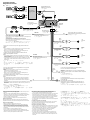
Fuse (10 A)
Fusible (10 A)
«OI• (10A)
7
BUS AUDIO IN
AMP REM
Blue/white striped
Con raya azul/blanca
´¯ƒ¡¥ƒ–łfl
Max. supply current 0.3 A
Corriente máx. de alimentación de 0,3 A
‡⁄j·£¤„q‹y 0.3 A
Max. supply current 0.1 A
Corriente máx. de alimentación de 0,1 A
‡⁄j·£¤„q‹y 0.1 A
ANT REM
Blue
Azul
´¯ƒ
Sky blue
Azul celeste
⁄ ´¯ƒ
ATT
Red
Rojo
‹ıƒ
Yellow
Amarillo
¶ƒ
Black
Negro
¶´ƒ
Purple
Púrpura
ƒ
Green
Verde
”æƒ
Grey
Gris
ƒ˙ƒ
White
Blanco
¥ƒ
Right
Derecho
¥k
Left
Izquierdo
¥“
Right
Derecho
¥k
Left
Izquierdo
¥“
to AMP REMOTE IN of the optional power amplifier
This connection is only for ampilifiers. Connecting any other system may
damage the unit.
a AMP REMOTE IN del amplificador de potencia opcional.
Esta conexión es sólo para amplificadores. La conexión de cualquier otro
sistema puede dañar la unidad.
ƒ¿`˚“”¥\†v'æ⁄j „“” AMP REMOTE IN¡]'æ⁄j „»»––¿Ø⁄J¡^¡C
¥»‡s– ¶¨¥˛''æ⁄j „¡C‡s–¥ƒ¤¥ƒ¤t†˛¥ifl•|•l˜[¥» ¡C
Source selector
Selector de fuente
› •‰¿ „
Supplied with the CD/MD changer
Suministrado con el cambiador de CD/MD
“–a' CD/MD ·«”—
Supplied with the XA-C30
Suministrado con el XA-C30
“–a' XA-C30
RCA pin cord (not supplied)
Cable con clavijas RCA (no suministrado)
RCA ”‚}„q‰u¡]L“–a¡^
Notes on the control and power supply leads
• The power aerial control lead (blue) supplies +12 V DC when you turn on
the unit.
• When your car has a built-in FM/AM aerial in the rear/side glass, it is
necessary to connect the power aerial control lead (blue) or the accessory
power input lead (red) to the power terminal of the existing aerial
booster. For details, consult your dealer.
• A power aerial without a relay box cannot be used with this unit.
Memory hold connection
When the yellow power input lead is connected, power will always be
supplied to the memory circuit even when the ignition switch is turned off.
Notes on speaker connection
• Before connecting the speakers, turn the unit off.
• Use speakers with an impedance of 4 to 8 ohms, and with adequate
power handling capacities. Otherwise, the speakers may be damaged.
• Do not connect the terminals of the speaker system to the car chassis,
and do not connect the terminals of the right speaker with those of the
left speaker.
• Do not attempt to connect the speakers in parallel.
• Do not connect any active speakers (with built-in amplifiers) to the
speaker terminals of the unit. Doing so may damage the active speakers.
Be sure to connect passive speakers to these terminals.
Notas sobre los cables de control y de fuente de alimentación
• El conductor de control de la antena motorizada (azul) suministrará
+ 12 V CC cuando conecte la alimentación de la unidad.
• Si se ha instalado una antena de recepción de FM/AM en el cristal trasero
lateral del automóvil, es necesario conectar el cable de control de la
antena motorizada (azul) o el cable auxiliar de entrada de alimentación
(rojo) al terminal de alimentación del amplificador de antena existente.
Para obtener información detallada, consulte a su proveedor.
• Con esta unidad no podrá emplearse una antena motorizada desprovista
de caja de relé.
Conexión para protección de la memoria
Si conecta el cable de entrada de alimentación amarillo, el circuito de la
memoria siempre recibirá alimentación, aunque ponga la llave de
encendido en la posición de apagado.
Notas sobre la conexión de los altavoces
• Antes de conectar los altavoces, desconecte la alimentación de la unidad.
• Utilice altavoces con una impedancia de 4 a 8 Ohmios, y con la potencia
máxima admisible adecuada, ya que de lo contrario podría dañarlos.
• No conecte los terminales del sistema de altavoces al chasis del
automóvil, ni los del altavoz izquierdo a los del derecho.
• No intente conectar los altavoces en paralelo.
• No conecte altavoces activos (con amplificadores incorporados) a los
terminales de altavoces de la unidad. Si lo hiciese, podría dañar tales
altavoces. Por lo tanto, cerciórese de conectar altavoces pasivos a estos
terminales.
––¤ 'M„q•‰‰u¶•“
•
•–z¥·¶} „fi ¡A„q ˚⁄ ‰u“”––¤ ‰u¡]´¯ƒ ¡^§Y¥io¥˝12V“‰‹y„q¡C
•
–z“”¤T¤fi“”«Æ¡ …‹`… ¡⁄⁄ƒp“G⁄”‚¸ƒ‡ FM/AM ⁄‰u¡A§Y‰—§ „q ˚⁄ ‰u––¤ ‰u
¡]´¯ƒ ¡^'˛»†§U“”„q•‰¿Ø⁄J ‰u¡]‹ıƒ ¡^‡s–¤†{ƒ‡“”⁄ ‰u…W£„“”„q•‰” ⁄l⁄W¡
C
‚ † ⁄”fie¡A‰—‹¢‚¥''–¡C
•
¥» ⁄£fl ¤ˇ¥˛⁄£¤ª‡˘˜~„q‰c“”„q ˚⁄ ‰u¡C
«O«ø O —¥\fl “”‡s–“k
•‡s–ƒn¶ƒ„q•‰¿Ø⁄J ‰ufi¡A§Y¤ˇ¤T¤fi o ˚´I⁄ı˘_ ˝‡Q´ƒb„q•‰⁄`´_⁄§‡B
¡
„q•‰⁄·˜~˜–N„q‹y¤„O —¥\fl ¥˛„q‚¡A¥H«O«ø'O— “”…˘ ¡C
‡s–·›`n „¶•“
•
‡s–·›`n „„q‰u⁄§«e¡A‰—¥ ˆ –…¥» „q•‰¡C
•
‰—¤ˇ¥˛ 4 ƒ 8 £[ “ § ¤ˆ¥B¤ªƒ‡¤‹ ¥\†v“”·›`n „¡C§_«h•|•lˆa·›`n „¡C
•
⁄£¥i–N·›`n „“”” ⁄l‡s–ƒ¤T¤fi'‡‰L¡A⁄]⁄£¥i–N¥“·›`n „'M¥k·›`n „‹ ‡s–
•
⁄£¥i¤ˆ`p·›`n „¡C
•
⁄£¥i‡s– ƒ‡•‰·›`n „¡]⁄”‚¸ƒ‡'æ⁄j „“ ¡^ƒ ¥» “”·›`n „” ⁄l¡C§_«h•|•lˆaƒ
·›`n „¡Cƒ]ƒ„¡A‡o¤˙” ⁄l¥ufl‡s– L•‰·›`n „¡C
XR-CA320X
XR-CA320
to the +12 V power terminal which is energized at all times
Be sure to connect the black earth lead first.
a un terminal de alimentación de +12 V que esté permanentemente
activado
Asegúrese de conectar primero a este terminal el conductor de puesta a
masa negro.
ƒ‚g–‘‡£‡q„q“” +12 V „q•‰” ⁄l
¨‰—›”¥ ‡s–¶´ƒ–ƒa ‰u¡C
to a metal place in the car
First connect the black earth lead, then connect the yellow and red
power input leads.
a un punto metálico del automóvil
En primer lugar, conecte el conductor de puesta a masa negro y, a
continuación, los cables de entrada de alimentación amarillo y rojo.
ƒ¤T¤fi“”“ ˜ ‡¡ƒ
›”¥ ‡s–¶´ƒ–ƒa ‰u¡AM«ÆƒA‡s–¶ƒ'M‹ıƒ „q•‰¿Ø⁄J ‰u¡C
Connection diagram
Diagramas de conexión
‰u‚‡s–„ˇ
White/black striped
Con raya blanco/negro
¥ ¡ ¶´–łfl
Grey/black striped
Con raya gris/negro
ƒ˙¡ ¶´–łfl
Green/black striped
Con raya verde/negro
”æ¡ ¶´–łfl
Purple/black striped
Con raya púrpura/negro
¡ ¶´–łfl
-
 1
1
-
 2
2
-
 3
3
-
 4
4


Sony XR-CA320 Guía de instalación
- Tipo
- Guía de instalación
- Este manual también es adecuado para
en otros idiomas
- English: Sony XR-CA320 Installation guide
Artículos relacionados
-
Sony CDX-CA580X Manual de usuario
-
-
-
-
-
-
-
-
-