Simpson Strong-Tie JB212 Guía de instalación
- Tipo
- Guía de instalación

Every day we work hard to earn
your business, blending the talents
of our people with the quality of our
products and services to exceed
your expectations. This is our
pledge to you.
Nos esforzamos fuerte diariamente
combinando el talento de nuestro
personal con la calidad de nuestros
productos y servicios excediendo
sus expectativas para tenerlo a
usted como cliente. Este es nuestro
compromiso para con usted.
800-999-5099
www.strongtie.com
The information in this guide is intended to show contractors how our products
should be installed. It is not intended for use by Designers. Designers should refer to
the current Simpson Strong-Tie
®
Wood Construction Connectors catalog for loads
and other critical design information.
La información de esta guía tiene la intención de mostrarles a los contratistas como
deben instalar nuestros productos. No está diseñada para que la usen los diseñadores.
Los diseñadores deben referirse al catálogo actual de Conectores para Construcciones
de Madera para determinar las cargas y demás información crítica para el diseño.
INSTALLER’S
POCKET
GUIDE
GUÍA DE
BOLSILLO PARA
EL INSTALADOR
S-INSTALL09
S-INSTALL09 10/09 exp. 1/14
© 2009 Simpson Strong-Tie Company Inc.
Printed in the U.S.A.

2 3
Simpson Strong-Tie
QUESTIONS?
¿PREGUNTAS?
(800) 999-5099
This guide is intended to provide a quick reference tool to aid in the
correct installation of Simpson Strong-Tie
®
products. It is important
that users follow any installation guidelines specifi ed by the Designer
and refer to the current Simpson Strong-Tie Wood Construction
Connectors catalog for other important installation information.
This guide is not intended for use as a design tool by Designers.
Please see the current Simpson Strong-Tie Wood Construction
Connectors catalog for complete technical data and other important
design information.
Esta guía tiene como objetivo servir como herramienta de referencia
rápida para facilitar la correcta instalación de los productos Simpson
Strong-Tie
®
. Es importante que los usuarios sigan todas las pautas
de instalación especifi cadas por el diseñador y consulten el catálogo
de Conectores para Construcciones de Madera de Simpson Strong-
Tie para obtener más información importante sobre la instalación.
Esta guía no está ideada para ser usada como herramienta de diseño
por parte de diseñadores. Consulte el catálogo de Conectores para
Construcciones de Madera de Simpson Strong-Tie para conocer
todos los datos técnicos y otros datos importantes de diseño.

4 5
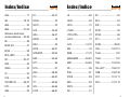
Index/IndiceIndex/Indice
A35 ............................. 17
AB .......................... 18-19
ABA ............................. 20
ABU ........................ 21-23
Adhesive Anchoring/
Anclaje Adhesivo .... 24-25
BC ............................... 26
BCS2-2/4 .................... 27
BC40 ........................... 28
BPS-LBPS ................... 29
CB .......................... 30-31
CBQ ............................. 32
CBSQ .......................... 33
CC ............................... 34
CCQ ............................. 35
CS/CMST14 ........... 36-37
DTC ............................. 38
GBC ............................. 39
H1 .......................... 40-41
H2.5A .......................... 42
H2.5T .......................... 43
H10 ........................ 44-45
HDA ....................... 46-47
HDQ8 .......................... 48
HDU ............................ 49
HETA ...................... 50-51
HPAHD22 ............... 52-53
HSS ........................ 54-55
HTT ............................. 56
HTU ............................. 57
HUS ....................... 58-59
ITS ......................... 60-61
ITT ......................... 62-63
IUS ......................... 64-65
LGT2 ...................... 66-67
LS ............................... 68
LSSU ........................... 69
LSTA ........................... 70
LTHJR ......................... 71
LTP4/LTP5 ................... 72
LUCZ ........................... 73
LUS ........................ 74-75
MA .............................. 76
MAB ....................... 77-79
MASA/MAS ............ 80-83
MST ....................... 84-85
PB ............................... 86
PHD ............................ 87
PSPN .......................... 88
RBC ............................. 89
RSP4 ........................... 90
SB ............................... 91
SP ............................... 92
SP4 ............................. 93
SSP ............................. 94
SSTB ........................... 95
STHD .......................... 96
STC ............................. 97
SUR/L .................... 98-99
THA .................... 100-101
THJA ......................... 102
THJU ......................... 103
TSB .................... 104-105
Titen HD
®
........... 106-107
TWB ................... 108-109
VGT .................... 110-111
VPA .................... 112-113

6 7
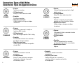
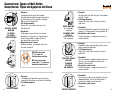
Connectors: Types of Nail Holes
Conectores: Tipos de Agujeros de Clavo
ROUND
REDONDO
• Purpose:
To fasten a connector.
• Fill Requirements:
Always fi ll, unless otherwise noted.
• Propósito:
Para fi jar un conector.
• Requisitos para Llenar:
Llénelo siempre, salvo que se indique
lo contrario.
TRIANGULAR
• Purpose:
To increase a connector’s strength or
to achieve MAX strength.
• Fill Requirements:
When the Designer specifi es “Max” nailing.
• Propósito:
Para aumentar la fuerza de un conector o
para lograr una fuerza máxima.
• Requisitos para Llenar:
Llénelo cuando el diseñador lo especifi ca
clavado "Máx.".
HEXAGONAL
• Purpose:
To fasten a connector to concrete
or masonry.
• Fill Requirements:
Always fi ll when fastening a connector
to concrete or fastening a connector
with masonry screws.
OBROUND
ALARGADO
• Purpose:
To make fastening a connector in a tight
location easier.
• Fill Requirements:
Always fi ll, unless otherwise noted.
• Propósito:
Para fi jar un conector en una locación
apretada con el fi n de facilitar el trabajo.
• Requisitos para Llenar:
Llénelo siempre, salvo que se indique
lo contrario.
DIAMOND
DIAMANTE
• Purpose:
To temporarily fasten a connector to make
installing it easier.
• Fill Requirements:
None.
• Propósito:
Para fi jar temporalmente un conector,
con el propósito de facilitar su instalación.
• Requisitos para Llenar:
Ninguno.
• Propósito:
Para fi jar un conector a concreto o
mampostería.
• Requisitos para Llenar:
Siempre llénelo al fi jar un conector a
concreto o al fi jar un conector con tornillos
de mampostería.

8 9
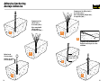
DOME NAILING
U.S. Patent No.
5,603,580
CLAVADO CON
CÚPULA
Patente de EE.UU.
No. 5,603,580
• Purpose:
To guide the nail into the joist and header
at a 45° angle.
• Fill Requirements:
Always fi ll, and make sure you use the
right nail.
• Propósito:
Con este dispositivo se guían el clavo en la
vigueta y la viga cabezal en ángulo de 45°.
• Requisitos para Llenar:
Llénelo siempre, y asegúrese de usar el
clavo correcto.
DIENTES RÁPIDOS
• Propósito:
Se usan para colocar el conector y fi jarlo
temporalmente, con el fi n de facilitar y
hacer más rápida su instalación.
• Requisitos para Llenar:
Ninguno.
• Purpose:
Provided when wood splitting may occur,
and to speed installation.
• Fill Requirements:
Always fi ll, and make sure you use the
right nail.
• Propósito:
Se usa cuando la madera puede rajarse o
abrirse y con el propósito hacer más
rápida la instalación.
• Requisitos para Llenar:
Llénelo siempre, y asegúrese de usar el
clavo correcto.
POSITIVE-ANGLE
NAILING
CLAVADO
EFECTIVO
EN ÁNGULO
Connectors: Types of Nail Holes
Conectores: Tipos de Agujeros de Clavo
DOUBLE-SHEAR
NAILING
CLAVADO
DE DOBLE
PENETRACIÓN
• Purpose:
Installed into the joist and header,
distributing the load through two points
on each joist nail for greater strength.
Must use full length nail.
• Fill Requirements:
Always fi ll, and make sure you use
the right nail.
• Propósito:
Para lograr mayor fuerza, los clavos
penetran a la vigueta y la viga cabezal,
así distribuyendo la carga entre las
dos puntas de cada clavo.
• Requisitos para Llenar:
Llénelo siempre, y asegúrese de usar
el clavo correcto.
• Purpose:
To temporarily position and secure the
connector for easier and faster installation.
• Fill Requirements:
None.
DO NOT use short
(1¹⁄₂") nails for
double-shear nailing.
NO usen los clavos
cortos de 1¹⁄₂" para uso
de doble penetración.
SPEED PRONGS

10 11
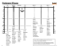
Fasteners/Clavos
(0.162")
16dx2¹⁄₂"
3x Wood
nailers.
NOT for
double shear
nailing unless
approved by
Designer.
16dx2¹⁄₂"
Para madera
de 3". NO
para clavado
de double
penetración
salvo que así
lo apruebe el
diseñador.
(0.162")
16d Common
Straps, heavy
hangers, plated
truss and SCL
connectors.
16d Común
Cintas, soporte
de viga pesadas,
para cerchas
y madera
composito.
16d 16dx2
1
⁄
2
" 16d Sinker 10d 10dx1
1
⁄
2
" 8d 8dx1
1
⁄
2
"
(0.148")
16d Sinker
Straps,
hangers,
header
fastening.
16d Sinker
Cintas,
soporte
de viga.
(0.148")
10d Common
Straps,
hangers,
header
fastening.
10d Común
Cintas,
soporte
de viga.
Same
uses
Mismo
uso
(0.148")
10dx1¹⁄₂"
2x Joist nailing.
Caution: Load
reduction if used
as header
nails.
Galvanized
nail shown.
10dx1¹⁄₂"
Clavado de
vigas 2x.
Cuidado: Reduce
la capacidad
si se usa en la
viga cabezal.
Se muestra un
clavo galvanizado.
(0.131")
8dx1¹⁄₂"
Light duty
framing anchors
and some
rafter ties.
Galvanized
nail shown.
8dx1¹⁄₂"
Conectores
ligeros y
“clips” de
huracán.
Se muestra
un clavo
galvanizado.
(0.131")
8d Common
Rafter ties.
8d Común
“Clips” de
huracán.
When using stainless-steel connectors, use stainless-steel
fasteners. When using ZMAX
®
/hot-dip galvanized connectors,
use fasteners galvanized per ASTM A153.
Al usar los conectores del acero inoxidable, utilice los sujetadores
del acero inoxidable. Al usar conectores ZMAX
®
/HDG galvanizados,
utilizan los sujetadores galvanizados por ASTM A153.

12 13
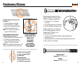
Fasteners/Clavos
Framing nail-gun nails can only
be used if:
1. Correct diameter and length
2. Correct quantity is installed
3. Driven with a hole location tool
(fi nds the hole) or by hand
NOTE: .121 may NOT be used to
replace 10d or 16d nails.
Sólo se pueden utilizar clavos
estructurales para pistola si:
1. Tengan diámetro y tamaño correcto
2. Se instala la cantidad correcta
3. Usan maquina que encuentre el
agujero, o se clavan a mano
NOTA: NO se pueden utilizar clavos 121
como sustitutos de clavos 10d o 16d.
DO NOT OVERDRIVE
NO SHOOTING-THRU
CONNECTORS
NO SE METE
DEMASIADO
NO SE PUEDE
HACER AGUJEROS
CON MAQUINA
Common screws may NOT
be used to replace NAILS
in connectors.
NO se puede usar
tornillos comunes en vez
de CLAVOS en conectores.
Some connectors install with the
Simpson Strong-Tie
®
Strong-Drive
®
(SDS) ¹⁄₄" structural wood screw.
1. Install with ³⁄₈" hex socket or
nut driver
2. Pre-drilling generally not required
3. Do not substitute with lag screws
Algunos conectores se instalan con
el tornillo para madera estructural
Strong Drive
®
(SDS) de ¹⁄₄" de
Simpson Strong-Tie
®
.
1. Instalar con un destornillador de casquillo hexagonal o
de tuercas de ³⁄₈"
2. Generalmente no es necesario efectuar perforaciones previas
3. No sustituir con tirafondos
MACHINE BOLT
Diameter: ¹⁄₂, ⁵⁄₈, ³⁄₄, ⁷⁄₈, 1
PERNOS
Diametro: ¹⁄₂, ⁵⁄₈, ³⁄₄, ⁷⁄₈, 1
CCQ IN 3

14 15
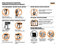
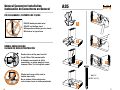
General Connector Installation
Instalación de Conectores en General
TOP FLANGE HANGERS / SOPORTES CON ALA SUPERIOR
Hanger over-spread
Soporte demasiado abierto
Hanger not plumb
Soporte fuera de plomo
WOOD NAILERS / LISTONES CLAVADORES DE MADERA
PREVENT ROTATION / EVITAR LA ROTACIÓN
Shorter hanger with no web stiffener
results in rotation
Un soporte colgante más corto sin de
entramado permitirá la rotación
Correct attachment
Montaje correcto
Nailer too wide
Listón clavador muy ancho
Nailer too narrow
Listón clavador muy estrecho
Nailer too thin
Listón clavador demasiado
delgado
TOE-NAILING / CLAVADO EN DIAGONAL
Do not toe nail I-joists before installing
top fl ange or face mount hangers
No clave en ángulo las viguetas ‘I’ antes
de montar los soportes (con o sin ala
superior)
POSITIVE ANGLE NAILING
CLAVADO EFECTIVO EN ÁNGULO
Correct nailing
approx. 45° angle
Clavado correcto
aproximadamente
a 45°
Nail at wrong angle
Clavado con un
ángulo incorrecto
Nail too long
Clavos demasiado
largos
¹⁄₄"
or less

16 17
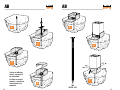
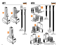
General Connector Installation
Instalación de Conectores en General
ITS/IUS HANGERS / SOPORTES DE ITS/IUS
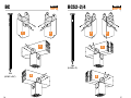
A35
DOUBLE SHEAR NAILING
CLAVADO DE DOBLE PENETRACIÓN
Double-shear nailing must use full
length 10d or 16d common nails
Al trabajar con clavado de doble
penetración, se deben emplear clavos
comunes 10d o 16d de longitud normal
Shorter nails may not be used as
double-shear nails
No se pueden utilizar clavos más
cortos como clavos de doble penetración
DO NOT make your own holes
DO NOT nail bottom chord
NO haga otros orifi cios para los clavos
NO clave en la viga inferior
1
2
8dx1¹⁄₂"
(0.131" x 1¹⁄₂")
3
4
2
3
1

18 19
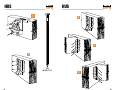
ABAB
1
10d
(0.148" x 3")
If using an adhesive
anchor, see page 24
for instructions.
Si utiliza un anclaje
adhesivo, consulte las
instrucciones de la
página 24.
2
3
4
5
6
7

20 21
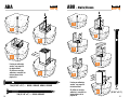
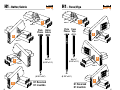
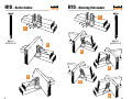
ABU – Nails/ClavosABA
16d
(0.162" x 3¹⁄₂")
1
2
3
4
If using an adhesive
anchor, see page 24
for instructions.
Si utiliza un anclaje
adhesivo, consulte las
instrucciones de la
página 24.
If using an adhesive
anchor, see page 24
for instructions.
Si utiliza un anclaje
adhesivo, consulte las
instrucciones de la
página 24.
1
2
3
4
5
6
10d (0.148" x 3") – ABA44, ABA44R
16d (0.162" x 3¹⁄₂") – ABA46, ABA46R, ABA66, ABA66R

22 23
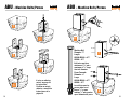
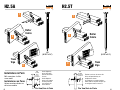
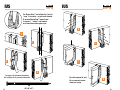
ABU – Machine Bolts/PernosABU – Machine Bolts/Pernos
2
4
5
3
If using an adhesive
anchor, see page 24
for instructions.
Si utiliza un anclaje
adhesivo, consulte las
instrucciones de la
página 24.
Machine Bolt
Diameter:
1
⁄
2
"
Length:
ABU44/ABU46 = 4
1
⁄
2
"
ABU66 = 6
1
⁄
2
"
Bolt holes must be a
minimum of
1
⁄
32
" and a
maximum of
1
⁄
16
" larger
than bolt diameter.
Perno Torneado
Diámetro:
1
⁄
2
"
Largo:
ABU44/ABU46 = 4
1
⁄
2
"
ABU66 = 6
1
⁄
2
"
Los orificios para los
pernos deben ser al
menos
1
⁄
32
" y como
máximo
1
⁄
16
" más grandes
que el diámetro del perno.
1
2
3
4
5
6
7
8

24 25
Fill 1/2 to 2/3
Llene 1/2 a 2/3
Adhesive Anchoring
Anclaje Adhesivo
2
3
1
4
5
6
Compressed air
(80 psi min.),
4 seconds (min.)
Aire comprimido
(80 psi mín.),
4 segundos (mín.)
Compressed air (80 psi min.),
4 seconds (min.)
Aire comprimido (80 psi mín.),
4 segundos (mín.)
Dispense until uniform color
Aplique hasta lograr un color
uniforme
Nylon brush
4 cycles (min.)
Cepillo de nailon
4 ciclos (mín.)
7

26 27
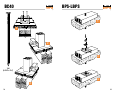
BCS2-2/4BC
3
16d
(0.162" x 3¹⁄₂")
1
2
3
4
1 2
10d
(0.148" x 3")
4

28 29
BPS-LBPSBC40
16d
(0.162" x 3¹⁄₂")
2
1
3
1
2
3

30 31
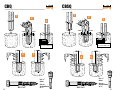
CB –
Machine Bolts/Pernos
CB –
Machine Bolts/Pernos
3
1
2
3" Side
cover
(min.)
Cubierta
lateral de
3" (mín.)
Bolt holes must be a minimum
of
1
⁄
32
" and a maximum of
1
⁄
16
"
larger than bolt diameter.
Los orifi cios para los pernos
deben ser al menos
1
⁄
32
" y como
máximo
1
⁄
16
" más grandes que
el diámetro del perno.
3" Side
cover
(min.)
Cubierta
lateral de
3" (mín.)
5
6
Machine Bolt
Perno
4
Model
No./
N.º de
Modelo
Machine
Bolt Size/
Tamaño
del Perno
CB44
5
⁄
8
" x 4
1
⁄
2
"
CB46
5
⁄
8
" x 4
1
⁄
2
"
CB48
5
⁄
8
" x 4
1
⁄
2
"
CB64
5
⁄
8
" x 4
1
⁄
2
"
CB66
5
⁄
8
" x 6
1
⁄
2
"
CB68
5
⁄
8
" x 6
1
⁄
2
"
CB86
3
⁄
4
" x 8
1
⁄
2
"
CB88
3
⁄
4
" x 8
1
⁄
2
"
CB1010
3
⁄
4
" x 10
1
⁄
2
"
CB1012
3
⁄
4
" x 10
1
⁄
2
"
CB1212
3
⁄
4
" x 11
1
⁄
2
"

32 33
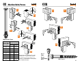
CBSQCBQ
3" min.3" min.
Concrete MUST cure
El concreto DEBE curar
3
4
1
2
5
Use
3
⁄
8
"
driver
Use un
destornillador
de
3
⁄
8
"
Use
3
⁄
8
"
driver
Use un
destornillador
de
3
⁄
8
"
3" min.3" min.
Concrete MUST cure
El concreto DEBE curar
1
2
3
4
5
SDS ¹⁄₄" x 2" SDS ¹⁄₄" x 2"

34 35
CCQCC –
Machine Bolts/Pernos
Use
3
⁄
8
"
driver
Use un
destornillador
de
3
⁄
8
"
1
3
4
Bolt holes must be a minimum of
1
⁄
32
" and a
maximum of
1
⁄
16
" larger than bolt diameter.
Los orifi cios para los pernos deben ser al
menos
1
⁄
32
" y como máximo
1
⁄
16
" más grandes
que el diámetro del perno.
Machine Bolt / Perno
Beam or
Column Width
Ancho de Dintel
o de Columna
Machine Bolt Size
Tamaño del Perno Torneado
Diameter
Diámetro
Length
Longitud
3
1
⁄
8
"
5
⁄
8
"4
1
⁄
2
"
3
1
⁄
2
"
5
⁄
8
"4
1
⁄
2
"
5
1
⁄
8
"
3
⁄
4
"6
1
⁄
2
"
5
1
⁄
2
"
5
⁄
8
"6
1
⁄
2
"
6
3
⁄
4
"
3
⁄
4
"8"
7"
3
⁄
4
"8"
7
1
⁄
2
"
3
⁄
4
"8
1
⁄
2
"
8
3
⁄
4
"
3
⁄
4
" 10"
9
1
⁄
2
"
3
⁄
4
" 10
1
⁄
2
"
1
2
3
4
5
6
SDS ¹⁄₄" x 2¹⁄₂"
2

36 37
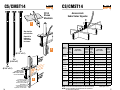
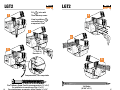
(CMST requires
minimum 2-2x studs)
(CMST requiere puntales
de 2-2x como mínimo)
Provide min. 1
5
/8" end
distance for CS and CMST
Dejar al menos 1
5
/8" y
distancia para CS y CMST
Equal number of
specified nails in each end
Igual cantidad de clavos
especificados en cada extremo
No nails
required here
No necesita
clavos aquí
CS/CMST14CS/CMST14
10d
(0.148" x 3")
CS14
Shown
Mostrado
Model/
Modelo
Lumber Species / Especies de Madera
Douglas Fir-Larch/Southern Pine Spruce-Pine-Fir/HemFir
End
Length/
Largo
del
Extremo
Cut Length/
Largo a Cortar
Total
Fasteners/
Total de
Clavos
End
Length/
Largo
del
Extremo
Cut Length/
Largo a Cortar
Total
Fasteners/
Total de
Clavos
CS14
CS14-R
15" Clear Span (Luz)+30" 26-10d 16" Clear Span (Luz)+32" 30-10d
16" Clear Span (Luz)+32" 30-8d 19" Clear Span (Luz)+38" 36-8d
CS16
CS16-R
13" Clear Span (Luz)+26" 22-8d 14" Clear Span (Luz)+28" 26-8d
11" Clear Span (Luz)+22" 20-10d 12" Clear Span (Luz)+24" 22-10d
CS18S
CS18S
CS18-R
11" Clear Span (Luz)+22" 18-8d 12" Clear Span (Luz)+30" 22-8d
9" Clear Span (Luz)+18" 16-10d 10" Clear Span (Luz)+24" 18-10d
CS20
CS20-R
9" Clear Span (Luz)+18" 14-8d 9" Clear Span (Luz)+18" 16-8d
6" Clear Span (Luz)+16" 12-10d 8" Clear Span (Luz)+16" 14-10d
CS22
CS22-R
6" Clear Span (Luz)+16" 14-8d 8" Clear Span (Luz)+20" 14-8d
5" Clear Span (Luz)+14" 12-10d 7" Clear Span (Luz)+18" 12-10d
CMST14
26" Clear Span (Luz)+52" 56-16d 30" Clear Span (Luz)+66" 66-16d
30" Clear Span (Luz)+60" 66-10d 34" Clear Span (Luz)+76" 76-10d
See chart for
nail selection
Consulte la
tabla para
seleccionar
los clavos
NOTE: Install half of the total fasteners in each end of strap. Clear Span = Luz
NOTA: Instale la mitad de la cantidad total de sujetadores
en cada extremo del fl eje.
3
Across Joists
Sobre Varias Viguetas
8d
(0.131" x 2¹⁄₂")
16d
(0.162" x 3¹⁄₂")
1
2

38 39
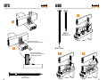
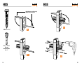
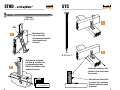
GBCDTC
2
3
1
Truss nails not driven flush
Los clavos de la cercha no deberían
asentarse contra el conector
Install nail in center of slot
Instale el clavo en el centro de la ranura
2
8d
(0.131" x 2¹⁄₂")
8d
(0.131" x 2¹⁄₂")
8dx1¹⁄₂"
(0.131" x 1¹⁄₂")
8d x 2
1
⁄
2
"
8d x 2
1
⁄
2
" 8d x 1
1
⁄
2
"
1

40 41
H1 – Truss/VigaH1 – Rafter/Cabrio
H1 Reversed
H1 Invertido
8dx1¹⁄₂"
(0.131" x 1¹⁄₂")
Rafter
Cabrio
8dx1¹⁄₂"
(0.131" x 1¹⁄₂")
Truss
Viga
Plate
Placas
8d
(0.131" x 2¹⁄₂")
Plate
Placas
8d
(0.131" x 2¹⁄₂")
1
1
3
3
4
4
2
2
8d x 2
1
⁄
2
"
8d x 2
1
⁄
2
"
8d x 1
1
⁄
2
"
8d x 1
1
⁄
2
"
8d x 1
1
⁄
2
"
8d x 1
1
⁄
2
"
H1 Reversed
H1 Invertido

42 43
H2.5TH2.5A
8d
(0.131" x 2¹⁄₂")
Installations in Pairs
Both connectors shall be
same model.
Plan View/Vista de Planta
Plan View/Vista de Planta
Install diagonally
across from each
other for minimum
2x truss.
Instale diagonal-
mente uno respecto
del otro para dejar
una cercha de 2x
como mínimo.
Products can be on the same side
of the wall provided they are
confi gured as shown.
Los productos se pueden instalar a
ambos lados de la pared siempre que
se confi guren como se muestra.
Instalaciones en Pares
Ambos conectores deben ser
del mismo modelo.
8d
(0.131" x 2¹⁄₂")
Truss
Viga
1
2
2
Truss
Viga
3
3
1
Rafter
Cabrio
Rafter
Cabrio
Wall
Top Plate
Placa
superior
de la pared
Placa superi
o
de la pared
Wall
Top Plate

44 45
H10 – Blocking/EntramadoH10 – Rafter/Cabrio
3
8dx1¹⁄₂"
(0.131" x 1¹⁄₂")
8dx1¹⁄₂"
(0.131" x 1¹⁄₂")
1
1
2
2
4
5
3

46 47
HDA –
Machine Bolts/Pernos ⁵⁄₈-1"
HDA
1
2
3
4
5
Machine bolts should be at
least 1" longer than wood
member thickness.
Bolt holes must be a minimum
of
1
⁄
32
" and a maximum of
1
⁄
16
"
larger than bolt diameter.
Los pernos torneados deben ser
al menos 1" más largos que el
espesor de los miembros de
madera.
Los orifi cios para los pernos
deben ser al menos
1
⁄
32
" y como
máximo
1
⁄
16
" más grandes que
el diámetro del perno.
Machine Bolt / Perno
Model No./
N.º de
Modelo
Machine Bolt
Diameter/
Diámetro del
Perno Torneado
HD2A
5
⁄
8
"
HD5A
3
⁄
4
"
HD6A
7
⁄
8
"
HD8A
7
⁄
8
"
HD10A
7
⁄
8
"
HD14A 1"

48 49
HDUHDQ8
2
Use
3
⁄
8
"
driver
Use un
destornillador
de
3
⁄
8
"
Use
3
⁄
8
"
driver
Use un
destornillador
de
3
⁄
8
"
SDS ¹⁄₄" x 3"
(Included / Incluida)
SDS ¹⁄₄" x 2¹⁄₂"
(Included / Incluida)
1
3
Square washer
required (included)
Se requiere una
arandela cuadrada
(incluida)
1
3
2

50 51
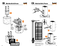
HETAHETA
10dx1¹⁄₂"
(0.131" x 1¹⁄₂")
Quantity per
Designer
Cantidad según
indicaciones del
diseñador
Concrete MUST cure
El concreto DEBE curar
1
2
3
4
5

52 53
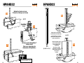
HPAHD22HPAHD22
1a
Nailed to block on form
Clavado al bloque en forma
Attached with StrapMate
®
strap holder
Fijar con sujetador de
abrazadera StrapMate
®
16d
(0.162" x 3¹⁄₂")
Concrete MUST cure
El concreto DEBE curar
StrapMate
®
strap holder
(SM1)
1b
or / ó
or / ó
2
3a
3b
Reduced loads apply.
Check with Designer
before nailing over
sheathing
Se aplican cargas
reducidas. Consulte
al diseñador antes de
clavar sobre
relleno
Strap may be bent down
and back up one time only
La abrazadera se puede
doblar hacia abajo y hacia
arriba sólo una vez

54 55
HSS HSS
SDS ¹⁄₄" x 1¹⁄₂"
Use
3
⁄
8
" driver
Use un
destornillador
de
3
⁄
8
"
Bend flanges one time only
Doble las alas una vez
1
2
3
4

56 57
HTUHTT
10d
(0.148" x 3")
10d
(0.148" x 3")
For double
2x joists
HTT4
HTT5
HTT16
HTT22
10d x 1¹⁄₂"
(0.148" x 1¹⁄₂")
16d x 2¹⁄₂"
(0.162" x 2¹⁄₂")
16d
(0.162" x 3¹⁄₂")
3
2
1
1
2
3
4
For double truss use 10d x 3" nails into trusses
Para cerchas dobles, use clavos
10d x 3" insertados en las cerchas
16d
16d
10dx1¹⁄₂"
10dx1¹⁄₂"

58 59
HUS
4
HUS
16d
(0.162" x 3¹⁄₂")
1
3
2
5

60 61
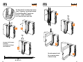
ITSITS
10d
(0.148" x 3")
The Strong-Grip™ seat allows the I-joist to
“snap” in securely – no joist nails needed.
El asiento Strong-Grip™ permite que
la viga ‘I’ “encaje” con fi rmeza;
no se necesitan clavos para vigas.
See pages 14-15 for more
information.
Vea la página 14-15 para
más información.
90°
10d
10d
1
2
3
4
5
6
7
No nails required in joist
No es necesario clavar
clavos en la viga

62 63
90°
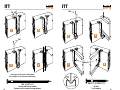
ITTITT
10d (0.148" x 3")
On top and face by header
Encima y en la cara de la viga cabezal
10dx1¹⁄₂
"
10d x 1¹⁄₂" (0.148" x 1¹⁄₂")
At joist
En la vigueta
See pages 14-15 for more information.
Vea la página 14-15 para más información.
1
2
10d
4
3
10d
5
6
7
8

64 65
IUSIUS
The Strong-Grip™ seat allows the I-joist to
“snap” in securely – no joist nails needed.
El asiento Strong-Grip™ permite que
la viga en ‘I’ “encaje” con fi rmeza;
no se necesitan clavos para vigas.
10d
(0.148" x 3")
See pages 14-15 for more information.
Vea la página 14-15 para más información.
1
2
3
4
5
6
7
8
No nails required in joist
No es necesario clavar
clavos en la viga

66 67
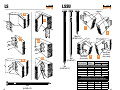
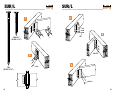
16d Sinker
(0.148" x 3¹⁄₄")
Titen
®
Masonry Screw/Tornillo para mampostería (¹⁄₄" x 2¹⁄₄")
For installation in concrete use Titen ¹⁄₄" x 1³⁄₄"
Para instalaciones en concreto, utilice Titen de ¹⁄₄" x 1³⁄₄"
LGT2LGT2
Fill holes with
Titen
®
masonry screws
Llene los orifi cios
con tornillos para
mampostería Titen
®
1
3
⁄
16
" Drill bit
Broca de
3
⁄
16
"
Compressed Air / Aire comprimido
2
3
4
5
6

68 69
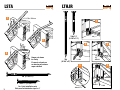
LSSULS
10d
(0.148" x 3")
10d
(0.148" x 3")
16d
(0.162" x 3¹⁄₂")
10d x 1¹⁄₂"
(0.148" x 1¹⁄₂")
16d or/ó 10d
(See table)
(Vea la tabla)
16d or/ó 10d
(See table)
(Vea la tabla)
10dx1½"
Joist Width
Ancho de Vigueta
Model
Modelo
Nails / Clavos
Face / Cara Joist / Viga
Sloped Only Hangers / Sólo Conectores Sesgados
1¹⁄₂ LSSU28 10-10d 5-10dx1¹⁄₂
1¹⁄₂ LSSU210 10-10d 7-10dx1¹⁄₂
2¹⁄₂ LSSUH310 18-16d 12-10dx1¹⁄₂
3 LSSU210-2 18-16d 12-10dx1¹⁄₂
3¹⁄₂ LSSU410 18-16d 12-10dx1¹⁄₂
Skewed Hangers or Sloped and Skewed
Conectores Sesgados o Con Sego y Pendiente
1¹⁄₂ LSSU28 9-10d 5-10dx1¹⁄₂
1¹⁄₂ LSSU210 9-10d 7-10dx1¹⁄₂
2¹⁄₂ LSSUH310 14-16d 12-10dx1¹⁄₂
3 LSSU210-2 14-16d 12-10dx1¹⁄₂
3¹⁄₂ LSSU410 14-16d 12-10dx1¹⁄₂
1a
1b
2a
3a
2b
3b
2
1
4
3

70 71
LTHJRLSTA
10dx1¹⁄₂"
(0.148" x 1¹⁄₂")
2³⁄₈" Min. / Mínimo
1
2
3
10d (0.148" x 3")
10d
(0.148" x 3")
1
2
3
4
5
10d
10d
10d
10dx1½"
10dx1½"
10dx1½"
10d x 1¹⁄₂" (0.148" x 1¹⁄₂")
For I-joist installation only
Sólo para instalación de vigas en ‘I’
Hanger not shown
for clarity
El soporte colgante no
se muestra para ofrecer
mayor claridad

72 73
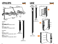
LUCZ
2
LTP4/LTP5
10dx1¹⁄₂"
(0.148" x 1¹⁄₂")
Header
Viga cabezal
Joist
Viga
16d
(0.162" x 3¹⁄₂")
8dx1¹⁄₂"
(0.131" x 1¹⁄₂")
8d
(0.131" x 2¹⁄₂")
Fasteners:
LTP4
No sheathing: 8dx1
1
⁄
2
"
Over sheathing (
3
⁄
8
" thick max.): 8dx2
1
⁄
2
"
LTP5
No sheathing: 8dx1
1
⁄
2
"
Over sheathing (
1
⁄
2
" thick max.): 8dx2
1
⁄
2
"
Sujetadores:
LTP4
Sin relleno: 8dx1
1
⁄
2
"
Sobre relleno (
3
⁄
8
" de espesor máx.): 8dx2
1
⁄
2
"
LTP5
Sin relleno: 8dx1
1
⁄
2
"
Sobre relleno (
1
⁄
2
" de espesor máx.): 8dx2
1
⁄
2
"
1
3

74 75
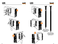
LUSLUS
16d for all others
16d para los demás
(0.162" x 3¹⁄₂")
10d for single 2x
10d para un solo 2x
(0.148" x 3")
1
2
3
4
5
6

76 77
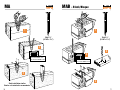
Concrete MUST cure
El concreto DEBE curar
3
/4"
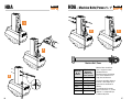
MAB – Block/Bloque
2
4
3
1
MA
10dx1¹⁄₂"
(0.148" x 1¹⁄₂")
Stud installation similar
Similar a la instalación en montantes
10dx1¹⁄₂"
(0.148" x 1¹⁄₂")
Concrete MUST cure
El concreto DEBE curar
1
2
3

78 79
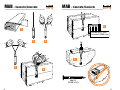
MAB – Concrete/ConcretoMAB – Concrete/Concreto
10dx1¹⁄₂"
(0.148" x 1¹⁄₂")
Concrete MUST cure
El concreto DEBE curar
1
2
4
5
3
6
7

80 81
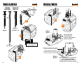
Concrete MUST cure
El concreto DEBE curar
MASA/MASMASA/MAS
2-8d
Duplex nails /
Clavo duplex
or/ó
1-10d
10dx1¹⁄₂"
(0.148" x 1¹⁄₂")
CONNECTOR
CONECTOR
8d
Duplex
10d
(0.148" x 3")
FORMING
ENCOFRADO
or/ó
1
2
Reduced loads apply, check with Designer
before nailing over sheathing
Se aplican cargas reducidas; consulte al
diseñador antes de clavar sobre el relleno
Reduced loads apply,
check with Designer
Se aplican cargas reducidas;
consulte al diseñador
Blocking required attached to sill with
A35Z (not shown) or per Designer
Se debe adjuntar un bloqueo al
larguero con A35Z (no se muestra)
o según indicaciones del diseñador
Option 1
Opción 1
Option 2
Opción 2
3
4
5

82 83
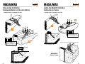
MASA/MAS MASA/MAS
MASAP/MASP
Similar / Similar
Brick-Ledge Installation
Instalación Sobre Cornisa de Ladrillos
Inside-the-Mudsill Installation
Instalación en Solera
3¹⁄₂
"
2x4 Plate
1
2-8d Duplex nails / Clavo duplex or/ó 1-10d
Concrete MUST cure
El concreto DEBE curar
2
2-8d Duplex nails / Clavo duplex or/ó 1-10d
1
Concrete MUST cure
El concreto DEBE curar
2

84 85
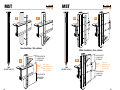
MST MST
16d
(0.162" x 3¹⁄₂")
No sheathing / Sin relleno
16d
(0.162" x 3¹⁄₂")
With sheathing / Con relleno
CLEAR
SPAN
No nails
required here
No necesita
clavos aquí
LARGO DEL
EXTREMO
END LENGTH
LARGO DEL
EXTREMO
END LENGTH
LUZ
CLEAR
SPAN
No nails
required here
No necesita
clavos aquí
LARGO DEL
EXTREMO
END LENGTH
LARGO DEL
EXTREMO
END LENGTH
LUZ
2
3
1
2a
3a
1a

86 87
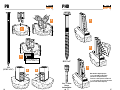
PB PHD
SDS ¹⁄₄" x 3"
Nut should be fi nger tight plus
¹⁄₃ to ¹⁄₂ turn with a hand wrench
(do not use an impact wrench)
La tuerca se debe ajustar a mano más
¹⁄₃ a ¹⁄₂ de vuelta con una llave de mano
(no usar una llave de impacto)
Use
3
⁄
8
" driver
Use un
destornillador
de
3
⁄
8
"
Concrete MUST cure
El concreto DEBE curar
2
4
5
3
1
1
2
3
16d
(0.162" x 3¹⁄₂")

88 89
PSPN RBC
16d
(0.162" x 3¹⁄₂")
10dx1¹⁄₂"
(0.148" x 1¹⁄₂")
3
/4"
Up to
Hasta
2
4
3
1
2
4
3
1

90 91
RSP4 SB
Install a minimum 45° from either edge
Instalar a mínimo 45° de cada cara
8dx1¹⁄₂"
(0.131" x 1¹⁄₂")
Embedment line
(top of concrete)
Línea de empotramiento
(parte superior del concreto)
24
24
24
2a
2b
1a
1b
2
1

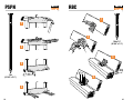
92 93
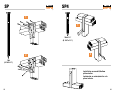
SP SP4
10d
(0.148" x 3")
10dx1¹⁄₂"
(0.148" x 1¹⁄₂")
Installation on mudsill/bottom
plate similar
Instalación en solera/similar a la
placa inferior
2
1
2
1

94 95
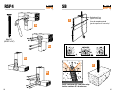
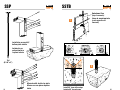
SSP SSTB
1
10d
(0.148" x 3")
Instalación en
solera/similar a
la placa inferior
Installation on mudsill/
bottom plate similar
Alternate with double top plate
Alterne con una placa superior
doble
Embedment line
(top of concrete)
Línea de empotramiento
(parte superior del
concreto)
Install 45° from either edge
Instalar 45° de cada cara
24
24
24
2

96 97
STC
8d
(0.131" x 2¹⁄₂")
Truss nails not driven fl ush
Los clavos de la cercha no
deberían asentarse contra
el conector
Install nail in center of slot
Instale el clavo en el centro
de la ranura
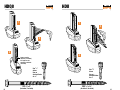
STHD – w/StrapMate
®
16d Sinker
(0.148 " x 3¹⁄₄")
Embedment line
(top of concrete)
Línea de empotramiento
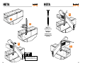
(parte superior del
concreto)
Concrete MUST cure
El concreto DEBE curar
SM1
1
2
Strap may be bent down
and back up one time only
La abrazadera se puede
doblar hacia abajo y hacia
arriba sólo una vez
1
2

98 99
SUR/L
16d
(0.162" x 3¹⁄₂")
10dx1¹⁄₂"
(0.148" x 1¹⁄₂")
SUR/L
2
4
5
3
1
16d
16d
10dx1½"
10dx1½"

100 101
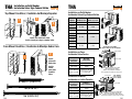
THA THA
2
3
1
16d (0.162" x 3¹⁄₂")
10dx1¹⁄₂" (0.148" x 1¹⁄₂")
10d (0.148" x 3")
Top-Mount Condition / Condición de Montaje Superior
Face Mount Condition / Condición de Montaje Sobre Cara
Model
Modelo
Top & Face
Encima & Cara
Carried Member
Miembro Soportado
THA29 16-10d 4-10d
THA213
14-10d 4-10d
THA413
THA218 18-10d 4-10d
THA218-2
22-16d 6-16d
THA418
THA422
THA222-2
THA422-2
30-16d 6-16d
THA426
Installation on Solid Header
Instalación Sobre Viga Cabezal Sólida
Nail Location
Ubicación de
Los Clavos
Qty / Nail
Cant./Clavo
Top / Encima 4-16d
Face / Cara 4-16d
Carried Member
Miembro soportado
Fill all holes with 16d
Llene todos los orifi cios
con clavos 16d.
Installation on Truss
Instalación Sobre Cercha
Nail Location
Ubicación de
Los Clavos
4x Nailer /
Listón Clavador 4x
Top / Encima 4-16d
Face / Cara 4-16d
Carried Member
Miembro soportado
Fill all holes with 16d
Llene todos los orifi cios
con clavos 16d.
Installation on Nailer
Instalación en Listón Clavador
Top / Encima
Straighten the double shear nailing
tabs and install nails straight
Enderece las pestañas de clavado de
doble penetración e instale los clavos rectos.
Double 2x4 Top Chord Min.
Viga Superior Doble de 2 x 4 Como Mínimo
Face / Cara
Min. 4x Nailer
Listón Clavador
4x Como Mínimo
Face / Cara
Top / Encima
Straighten the double shear nailing tabs
and install nails straight into the joist.
Enderece las pestañas de clavado de doble
penetración e instale los clavos rectos en la viga.
Install joist nails both sides
Instale clavos para vigas a ambos lados
Install
joist nails
both sides
Instale
clavos
para vigas
a ambos
lados
1
2
Installation on Solid Header
Instalación Sobre Viga Cabezal Sólida

102 103
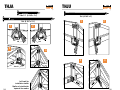
THJA
Left hand hip
installation similar
Similar a la instalación
‘izquierda’ de cumbre
THJU
10dx1¹⁄₂" (0.148" x 1¹⁄₂")
10d (0.148" x 3")
16d (0.162" x 3¹⁄₂")
2
1
16d
16d
4
10dx1½"
2
4
3
1
10dx1½"
3

104 105
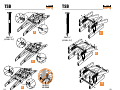
TSB
10dx1¹⁄₂"
(0.148" x 1¹⁄₂")
TSB
3
2
1
1
2
3
10dx1¹⁄₂"
(0.148" x 1¹⁄₂")
NO STEP
NO PISAR

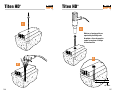
106 107
Titen HD
®
Titen HD
®
1
/2" min.
2
1
3
4
Washer or bearing plate as
required by building code
Arandela o disco de presión
según lo requiera el código
de construcción

108 109
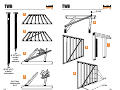
TWB
16d
(0.162" x 3¹⁄₂")
at plates/
en las soleras
8d
(0.131" x 2¹⁄₂")
at studs /
en los
montantes
Cut ⁵⁄₈" kerf
Corte un corte
de ⁵⁄₈"
TWB
2
4
3
1
5
6
8
7
8d
(2) 16d
(2) 16d

110 111
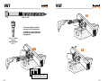
VGT VGT
Use
3
⁄
8
" driver
Use un
destornillador
de
3
⁄
8
"
If using an adhesive anchor,
see page 24 for instructions.
Si utiliza un anclaje adhesivo,
consulte las instrucciones de
la página 24.
SDS ¹⁄₄" x 3"
Concrete MUST cure
El concreto DEBE curar
1
2
3

112 113
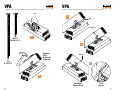
VPA
10d
(0.148" x 3")
VPA
Solid Wood
Madera Sólida
I-Joist
Vigueta
10dx1¹⁄₂"
(0.148" x 1¹⁄₂")
Required
Pitch
Inclinación
Requerida
3
4
5
10d
10d
10dx1½"
10dx1½"
2
1

114 115
Notes/Notas Notes/Notas

116 117
Notes/Notas Notes/Notas

118 119
Notes/Notas Notes/Notas
Transcripción de documentos
Every day we work hard to earn your business, blending the talents of our people with the quality of our products and services to exceed your expectations. This is our INSTALLER’S POCKET GUIDE pledge to you. Nos esforzamos fuerte diariamente combinando el talento de nuestro GUÍA DE BOLSILLO PARA EL INSTALADOR personal con la calidad de nuestros productos y servicios excediendo sus expectativas para tenerlo a usted como cliente. Este es nuestro compromiso para con usted. S-INSTALL09 800-999-5099 www.strongtie.com © 2009 Simpson Strong-Tie Company Inc. Printed in the U.S.A. S-INSTALL09 10/09 exp. 1/14 The information in this guide is intended to show contractors how our products should be installed. It is not intended for use by Designers. Designers should refer to the current Simpson Strong-Tie® Wood Construction Connectors catalog for loads and other critical design information. La información de esta guía tiene la intención de mostrarles a los contratistas como deben instalar nuestros productos. No está diseñada para que la usen los diseñadores. Los diseñadores deben referirse al catálogo actual de Conectores para Construcciones de Madera para determinar las cargas y demás información crítica para el diseño. Simpson Strong-Tie QUESTIONS? ¿PREGUNTAS? (800) 999-5099 This guide is intended to provide a quick reference tool to aid in the correct installation of Simpson Strong-Tie® products. It is important that users follow any installation guidelines specified by the Designer and refer to the current Simpson Strong-Tie Wood Construction Connectors catalog for other important installation information. This guide is not intended for use as a design tool by Designers. Please see the current Simpson Strong-Tie Wood Construction Connectors catalog for complete technical data and other important design information. Esta guía tiene como objetivo servir como herramienta de referencia rápida para facilitar la correcta instalación de los productos Simpson Strong-Tie®. Es importante que los usuarios sigan todas las pautas de instalación especificadas por el diseñador y consulten el catálogo de Conectores para Construcciones de Madera de Simpson StrongTie para obtener más información importante sobre la instalación. Esta guía no está ideada para ser usada como herramienta de diseño por parte de diseñadores. Consulte el catálogo de Conectores para Construcciones de Madera de Simpson Strong-Tie para conocer todos los datos técnicos y otros datos importantes de diseño. 2 3 Index/Indice A35 ............................. 17 H1 .......................... 40-41 LS ............................... 68 SP ............................... 92 AB .......................... 18-19 H2.5A .......................... 42 LSSU........................... 69 SP4 ............................. 93 ABA ............................. 20 H2.5T .......................... 43 LSTA ........................... 70 SSP ............................. 94 ABU........................ 21-23 H10 ........................ 44-45 LTHJR ......................... 71 SSTB ........................... 95 Adhesive Anchoring/ Anclaje Adhesivo .... 24-25 HDA ....................... 46-47 LTP4/LTP5................... 72 STHD .......................... 96 HDQ8 .......................... 48 LUCZ ........................... 73 STC ............................. 97 HDU ............................ 49 LUS ........................ 74-75 SUR/L .................... 98-99 HETA ...................... 50-51 MA .............................. 76 THA .................... 100-101 HPAHD22 ............... 52-53 MAB ....................... 77-79 THJA ......................... 102 HSS........................ 54-55 MASA/MAS ............ 80-83 THJU ......................... 103 CBQ............................. 32 HTT ............................. 56 MST ....................... 84-85 TSB .................... 104-105 CBSQ .......................... 33 HTU............................. 57 PB ............................... 86 Titen HD® ........... 106-107 CC ............................... 34 HUS ....................... 58-59 PHD ............................ 87 TWB ................... 108-109 CCQ............................. 35 ITS ......................... 60-61 PSPN .......................... 88 VGT .................... 110-111 CS/CMST14 ........... 36-37 ITT ......................... 62-63 RBC............................. 89 VPA .................... 112-113 DTC ............................. 38 IUS ......................... 64-65 RSP4........................... 90 GBC............................. 39 LGT2 ...................... 66-67 SB ............................... 91 BC ............................... 26 BCS2-2/4 .................... 27 BC40 ........................... 28 BPS-LBPS ................... 29 CB .......................... 30-31 4 Index/Indice 5 Connectors: Types of Nail Holes Conectores: Tipos de Agujeros de Clavo • Purpose: To fasten a connector. • Fill Requirements: Always fill, unless otherwise noted. ROUND REDONDO TRIANGULAR • Propósito: Para fijar un conector. • Requisitos para Llenar: Llénelo siempre, salvo que se indique lo contrario. • Purpose: To increase a connector’s strength or to achieve MAX strength. • Fill Requirements: When the Designer specifies “Max” nailing. • Propósito: Para aumentar la fuerza de un conector o para lograr una fuerza máxima. • Requisitos para Llenar: Llénelo cuando el diseñador lo especifica clavado "Máx.". HEXAGONAL 6 OBROUND ALARGADO • Purpose: To fasten a connector to concrete or masonry. • Fill Requirements: Always fill when fastening a connector to concrete or fastening a connector with masonry screws. DIAMOND DIAMANTE • Purpose: To make fastening a connector in a tight location easier. • Fill Requirements: Always fill, unless otherwise noted. • Propósito: Para fijar un conector en una locación apretada con el fin de facilitar el trabajo. • Requisitos para Llenar: Llénelo siempre, salvo que se indique lo contrario. • Purpose: To temporarily fasten a connector to make installing it easier. • Fill Requirements: None. • Propósito: Para fijar temporalmente un conector, con el propósito de facilitar su instalación. • Requisitos para Llenar: Ninguno. • Propósito: Para fijar un conector a concreto o mampostería. • Requisitos para Llenar: Siempre llénelo al fijar un conector a concreto o al fijar un conector con tornillos de mampostería. 7 Connectors: Types of Nail Holes Conectores: Tipos de Agujeros de Clavo DOUBLE-SHEAR NAILING CLAVADO DE DOBLE PENETRACIÓN • Purpose: Installed into the joist and header, distributing the load through two points on each joist nail for greater strength. Must use full length nail. • Fill Requirements: Always fill, and make sure you use the right nail. • Propósito: Para lograr mayor fuerza, los clavos penetran a la vigueta y la viga cabezal, así distribuyendo la carga entre las dos puntas de cada clavo. • Requisitos para Llenar: Llénelo siempre, y asegúrese de usar el clavo correcto. • Purpose: To guide the nail into the joist and header at a 45° angle. • Fill Requirements: Always fill, and make sure you use the right nail. DOME NAILING U.S. Patent No. 5,603,580 CLAVADO CON CÚPULA Patente de EE.UU. No. 5,603,580 • Purpose: Provided when wood splitting may occur, and to speed installation. • Fill Requirements: Always fill, and make sure you use the right nail. DO NOT use short (1¹⁄₂") nails for double-shear nailing. NO usen los clavos cortos de 1¹⁄₂" para uso de doble penetración. POSITIVE-ANGLE NAILING CLAVADO EFECTIVO EN ÁNGULO SPEED PRONGS • Propósito: Se usa cuando la madera puede rajarse o abrirse y con el propósito hacer más rápida la instalación. • Requisitos para Llenar: Llénelo siempre, y asegúrese de usar el clavo correcto. • Propósito: Se usan para colocar el conector y fijarlo temporalmente, con el fin de facilitar y hacer más rápida su instalación. • Requisitos para Llenar: Ninguno. • Purpose: To temporarily position and secure the connector for easier and faster installation. • Fill Requirements: None. 8 • Propósito: Con este dispositivo se guían el clavo en la vigueta y la viga cabezal en ángulo de 45°. • Requisitos para Llenar: Llénelo siempre, y asegúrese de usar el clavo correcto. DIENTES RÁPIDOS 9 Fasteners/Clavos 16d 16dx2 1⁄2" 16d Sinker 10d 10dx1 1⁄2" 8d 8dx1 1⁄2" Same uses Mismo uso (0.162") (0.162") 16d Common Straps, heavy hangers, plated truss and SCL connectors. 10 16d Común Cintas, soporte de viga pesadas, para cerchas y madera composito. 16dx2¹⁄₂" 3x Wood nailers. NOT for double shear nailing unless approved by Designer. 16dx2¹⁄₂" Para madera de 3". NO para clavado de double penetración salvo que así lo apruebe el diseñador. (0.148") (0.148") 16d Sinker Straps, hangers, header fastening. 16d Sinker Cintas, soporte de viga. 10d Common Straps, hangers, header fastening. 10d Común Cintas, soporte de viga. (0.148") (0.131") 10dx1¹⁄₂" 2x Joist nailing. Caution: Load reduction if used as header nails. Galvanized nail shown. 8dx1¹⁄₂" Light duty framing anchors and some rafter ties. Galvanized nail shown. 10dx1¹⁄₂" Clavado de vigas 2x. Cuidado: Reduce la capacidad si se usa en la viga cabezal. Se muestra un clavo galvanizado. (0.131") 8d Common Rafter ties. 8d Común “Clips” de huracán. 8dx1¹⁄₂" Conectores ligeros y “clips” de huracán. Se muestra un clavo galvanizado. When using stainless-steel connectors, use stainless-steel fasteners. When using ZMAX®/hot-dip galvanized connectors, use fasteners galvanized per ASTM A153. Al usar los conectores del acero inoxidable, utilice los sujetadores del acero inoxidable. Al usar conectores ZMAX®/HDG galvanizados, utilizan los sujetadores galvanizados por ASTM A153. 11 Fasteners/Clavos Some connectors install with the Simpson Strong-Tie® Strong-Drive® (SDS) ¹⁄₄" structural wood screw. 1. Install with ³⁄₈" hex socket or nut driver 2. Pre-drilling generally not required 3. Do not substitute with lag screws Framing nail-gun nails can only be used if: 1. Correct diameter and length 2. Correct quantity is installed 3. Driven with a hole location tool (finds the hole) or by hand NOTE: .121 may NOT be used to replace 10d or 16d nails. Sólo se pueden utilizar clavos estructurales para pistola si: 1. Tengan diámetro y tamaño correcto 2. Se instala la cantidad correcta 3. Usan maquina que encuentre el agujero, o se clavan a mano NOTA: NO se pueden utilizar clavos 121 como sustitutos de clavos 10d o 16d. DO NOT OVERDRIVE NO SHOOTING-THRU CONNECTORS NO SE METE DEMASIADO NO SE PUEDE HACER AGUJEROS CON MAQUINA Common screws may NOT be used to replace NAILS in connectors. NO se puede usar tornillos comunes en vez de CLAVOS en conectores. 12 Algunos conectores se instalan con CCQ IN 3 el tornillo para madera estructural Strong Drive® (SDS) de ¹⁄₄" de Simpson Strong-Tie®. 1. Instalar con un destornillador de casquillo hexagonal o de tuercas de ³⁄₈" 2. Generalmente no es necesario efectuar perforaciones previas 3. No sustituir con tirafondos MACHINE BOLT Diameter: ¹⁄₂, ⁵⁄₈, ³⁄₄, ⁷⁄₈, 1 PERNOS Diametro: ¹⁄₂, ⁵⁄₈, ³⁄₄, ⁷⁄₈, 1 13 General Connector Installation Instalación de Conectores en General TOP FLANGE HANGERS / SOPORTES CON ALA SUPERIOR PREVENT ROTATION / EVITAR LA ROTACIÓN Shorter hanger with no web stiffener results in rotation Un soporte colgante más corto sin de entramado permitirá la rotación Hanger over-spread Soporte demasiado abierto Hanger not plumb Soporte fuera de plomo TOE-NAILING / CLAVADO EN DIAGONAL Do not toe nail I-joists before installing top flange or face mount hangers No clave en ángulo las viguetas ‘I’ antes de montar los soportes (con o sin ala superior) WOOD NAILERS / LISTONES CLAVADORES DE MADERA ¹⁄₄" or less Correct attachment Montaje correcto Nailer too narrow Listón clavador muy estrecho 14 Nailer too wide Listón clavador muy ancho Nailer too thin Listón clavador demasiado delgado POSITIVE ANGLE NAILING CLAVADO EFECTIVO EN ÁNGULO Correct nailing approx. 45° angle Clavado correcto aproximadamente a 45° Nail at wrong angle Clavado con un ángulo incorrecto Nail too long Clavos demasiado largos 15 General Connector Installation Instalación de Conectores en General A35 ITS/IUS HANGERS / SOPORTES DE ITS/IUS 1 DO NOT make your own holes DO NOT nail bottom chord NO haga otros orificios para los clavos NO clave en la viga inferior 1 2 2 DOUBLE SHEAR NAILING CLAVADO DE DOBLE PENETRACIÓN Double-shear nailing must use full length 10d or 16d common nails Al trabajar con clavado de doble penetración, se deben emplear clavos comunes 10d o 16d de longitud normal 3 Shorter nails may not be used as double-shear nails No se pueden utilizar clavos más cortos como clavos de doble penetración 3 8d x 1¹⁄₂" (0.131" x 1¹⁄₂") 4 16 17 AB AB 1 5 2 6 3 If using an adhesive anchor, see page 24 for instructions. Si utiliza un anclaje adhesivo, consulte las instrucciones de la página 24. 18 7 4 10d (0.148" x 3") 19 ABA ABU – Nails/Clavos 1 1 2 2 3 3 4 If using an adhesive anchor, see page 24 for instructions. Si utiliza un anclaje adhesivo, consulte las instrucciones de la página 24. 4 16d (0.162" x 3¹⁄₂") – ABA46, ABA46R, ABA66, ABA66R 10d (0.148" x 3") – ABA44, ABA44R 20 5 If using an adhesive anchor, see page 24 for instructions. Si utiliza un anclaje adhesivo, consulte las instrucciones de la página 24. 6 16d (0.162" x 3¹⁄₂") 21 ABU – Machine Bolts/Pernos ABU – Machine Bolts/Pernos 1 2 Machine Bolt Diameter: 1⁄2" Length: ABU44/ABU46 = 4 1⁄2" ABU66 = 6 1⁄2" 3 4 5 If using an adhesive anchor, see page 24 for instructions. Si utiliza un anclaje adhesivo, consulte las instrucciones de la página 24. 22 6 7 Bolt holes must be a minimum of 1⁄32" and a maximum of 1⁄16" larger than bolt diameter. Perno Torneado Diámetro: 1⁄2" Largo: ABU44/ABU46 = 4 1⁄2" ABU66 = 6 1⁄2" Los orificios para los pernos deben ser al menos 1⁄32" y como máximo 1⁄16" más grandes que el diámetro del perno. 8 23 Adhesive Anchoring Anclaje Adhesivo Compressed air (80 psi min.), 4 seconds (min.) Aire comprimido (80 psi mín.), 4 segundos (mín.) Compressed air (80 psi min.), 4 seconds (min.) Aire comprimido (80 psi mín.), 4 segundos (mín.) 1 4 5 Dispense until uniform color Aplique hasta lograr un color uniforme Nylon brush 4 cycles (min.) Cepillo de nailon 4 ciclos (mín.) 3 24 2 Fill 1/2 to 2/3 Llene 1/2 a 2/3 6 7 25 BC BCS2-2/4 1 2 1 2 3 3 10d (0.148" x 3") 16d (0.162" x 3¹⁄₂") 26 4 4 27 BC40 BPS-LBPS 1 1 2 2 16d (0.162" x 3¹⁄₂") 3 3 28 29 CB – Machine Bolts/Pernos CB – Machine Bolts/Pernos 4 1 Machine Bolt Perno 2 3" Side cover (min.) 3" Side cover (min.) Cubierta lateral de 3" (mín.) Cubierta lateral de 3" (mín.) 3 30 Model No./ N.º de Modelo Machine Bolt Size/ Tamaño del Perno CB44 5 CB46 5 CB48 5 CB64 5 CB66 5 CB68 5 CB86 3 CB88 3 ⁄8" x 4 1⁄2" ⁄8" x 4 1⁄2" ⁄8" x 4 1⁄2" 5 ⁄8" x 4 1⁄2" ⁄8" x 6 1⁄2" ⁄8" x 6 1⁄2" ⁄4" x 8 1⁄2" ⁄4" x 8 1⁄2" ⁄4" x 10 1⁄2" CB1010 3 CB1012 3 CB1212 3 6 ⁄4" x 10 1⁄2" ⁄4" x 11 1⁄2" Bolt holes must be a minimum of 1⁄32" and a maximum of 1⁄16" larger than bolt diameter. Los orificios para los pernos deben ser al menos 1⁄32" y como máximo 1⁄16" más grandes que el diámetro del perno. 31 CBQ CBSQ 1 1 2 2 3 3 3" min. 3" min. 3" min. 3" min. Concrete MUST cure El concreto DEBE curar Concrete MUST cure El concreto DEBE curar 4 5 4 Use 3⁄8" driver Use 3⁄8" driver 32 SDS ¹⁄₄" x 2" Use un destornillador de 3⁄8" 5 SDS ¹⁄₄" x 2" Use un destornillador de 3⁄8" 33 CC – Machine Bolts/Pernos CCQ 1 1 2 2 3 4 3 5 Machine Bolt / Perno Machine Bolt Size Beam or Column Width Tamaño del Perno Torneado Ancho de Dintel Diameter Length o de Columna Diámetro Longitud 34 1 3 ⁄8" 5 3 1⁄2" 5 5 1⁄8" 3 1 5 ⁄2" 5 6 3⁄4" 3 7" 3 1 7 ⁄2" 3 8 3⁄4" 3 9 1⁄2" 3 ⁄8" 4 ⁄2" ⁄8" 4 1⁄2" ⁄4" 6 1⁄2" ⁄8" 6 1⁄2" ⁄4" 8" ⁄4" 8" ⁄4" 8 ⁄2" 4 1 1 ⁄4" 10" ⁄4" 10 1⁄2" 6 Bolt holes must be a minimum of 1⁄32" and a maximum of 1⁄16" larger than bolt diameter. Los orificios para los pernos deben ser al menos 1⁄32" y como máximo 1⁄16" más grandes que el diámetro del perno. Use 3⁄8" driver Use un destornillador de 3⁄8" SDS ¹⁄₄" x 2¹⁄₂" 35 CS/CMST14 CS/CMST14 CS14 Shown Mostrado Across Joists Sobre Varias Viguetas 1 See chart for nail selection Consulte la tabla para seleccionar los clavos Lumber Species / Especies de Madera Douglas Fir-Larch/Southern Pine Spruce-Pine-Fir/HemFir 2 8d (0.131" x 2¹⁄₂") 10d (0.148" x 3") ls re nai he No uired a q re cesit í ne qu No vos a cla 16d (0.162" x 3¹⁄₂") (CMST requires minimum 2-2x studs) (CMST requiere puntales de 2-2x como mínimo) Provide min. 15/8" end distance for CS and CMST Dejar al menos 15/8" y distancia para CS y CMST Equal number of specified nails in each end Igual cantidad de clavos especificados en cada extremo 36 3 End Length/ Total Fasteners/ Largo del Total de Clavos Extremo Model/ Modelo End Length/ Largo del Extremo CS14 CS14-R 15" Clear Span (Luz)+30" 26-10d 16" Clear Span (Luz)+32" 30-10d 16" Clear Span (Luz)+32" 30-8d 19" Clear Span (Luz)+38" 36-8d CS16 CS16-R 13" Clear Span (Luz)+26" 22-8d 14" Clear Span (Luz)+28" 26-8d 11" Clear Span (Luz)+22" 20-10d 12" Clear Span (Luz)+24" 22-10d CS18S CS18S CS18-R 11" Clear Span (Luz)+22" 18-8d 12" Clear Span (Luz)+30" 22-8d 9" Clear Span (Luz)+18" 16-10d 10" Clear Span (Luz)+24" 18-10d CS20 CS20-R 9" Clear Span (Luz)+18" 14-8d 9" Clear Span (Luz)+18" 16-8d 6" Clear Span (Luz)+16" 12-10d 8" Clear Span (Luz)+16" 14-10d CS22 CS22-R 6" Clear Span (Luz)+16" 14-8d 8" Clear Span (Luz)+20" 14-8d 5" Clear Span (Luz)+14" 12-10d 7" Clear Span (Luz)+18" 12-10d 26" Clear Span (Luz)+52" 56-16d 30" Clear Span (Luz)+66" 66-16d 30" Clear Span (Luz)+60" 66-10d 34" Clear Span (Luz)+76" 76-10d CMST14 Cut Length/ Largo a Cortar Cut Length/ Largo a Cortar NOTE: Install half of the total fasteners in each end of strap. NOTA: Instale la mitad de la cantidad total de sujetadores en cada extremo del fleje. Total Fasteners/ Total de Clavos Clear Span = Luz 37 DTC GBC 1 1 8d x 1¹⁄₂" (0.131" x 1¹⁄₂") 8d x 2 1⁄2" Install nail in center of slot Instale el clavo en el centro de la ranura 8d (0.131" x 2¹⁄₂") 2 Truss nails not driven flush Los clavos de la cercha no deberían asentarse contra el conector 38 8d (0.131" x 2¹⁄₂") 3 2 8d x 2 1⁄2" 8d x 1 1⁄2" 39 H1 – Rafter/Cabrio H1 – Truss/Viga 1 1 8d x 2 1⁄2" 8d x 2 ⁄2" 1 Plate Rafter Placas Cabrio Plate Truss Placas Viga 2 2 8d x 1 1⁄2" 3 8d x 1 1⁄2" 8d x 1 1⁄2" 8dx1¹⁄₂" (0.131" x 1¹⁄₂") 3 8d x 1¹⁄₂" (0.131" x 1¹⁄₂") 8d x 1 1⁄2" 8d (0.131" x 2¹⁄₂") 4 40 H1 Reversed H1 Invertido 8d (0.131" x 2¹⁄₂") 4 H1 Reversed H1 Invertido 41 H2.5A H2.5T 1 1 Rafter Cabrio Rafter Cabrio 2 2 8d (0.131" x 2¹⁄₂") 8d (0.131" x 2¹⁄₂") Truss Viga Installations in Pairs Both connectors shall be same model. Instalaciones en Pares Ambos conectores deben ser del mismo modelo. 42 Truss Viga 3 3 Wall Top Plate Placa superior de la pared Install diagonally across from each other for minimum 2x truss. Instale diagonalmente uno respecto del otro para dejar una cercha de 2x como mínimo. Plan View/Vista de Planta Wall Top Plate Placa superio de la pared Products can be on the same side of the wall provided they are configured as shown. Los productos se pueden instalar a ambos lados de la pared siempre que se configuren como se muestra. Plan View/Vista de Planta 43 H10 – Rafter/Cabrio H10 – Blocking/Entramado 1 1 8d x 1¹⁄₂" (0.131" x 1¹⁄₂") 8d x 1¹⁄₂" (0.131" x 1¹⁄₂") 2 2 3 3 4 5 44 45 HDA HDA – Machine Bolts/Pernos ⁵⁄₈-1" 1 5 4 2 Machine Bolt / Perno 3 Model No./ N.º de Modelo HD2A 5 HD5A 3 ⁄8" ⁄4" HD6A 7 HD8A 7 HD10A 7 HD14A 46 Machine Bolt Diameter/ Diámetro del Perno Torneado ⁄8" ⁄8" ⁄8" 1" Machine bolts should be at least 1" longer than wood member thickness. Bolt holes must be a minimum of 1⁄32" and a maximum of 1⁄16" larger than bolt diameter. Los pernos torneados deben ser al menos 1" más largos que el espesor de los miembros de madera. Los orificios para los pernos deben ser al menos 1⁄32" y como máximo 1⁄16" más grandes que el diámetro del perno. 47 HDQ8 HDU 1 1 2 2 3 3 Square washer required (included) Se requiere una arandela cuadrada (incluida) Use 3⁄8" driver Use un destornillador de 3⁄8" 48 Use 3⁄8" driver Use un destornillador de 3⁄8" SDS ¹⁄₄" x 3" SDS ¹⁄₄" x 2¹⁄₂" (Included / Incluida) (Included / Incluida) 49 HETA HETA 4 1 2 10d x 1¹⁄₂" (0.131" x 1¹⁄₂") Quantity per Designer Cantidad según indicaciones del diseñador 3 5 Concrete MUST cure El concreto DEBE curar 50 51 HPAHD22 1a HPAHD22 Nailed to block on form Clavado al bloque en forma 3a or / ó StrapMate® strap holder (SM1) 1b Strap may be bent down and back up one time only La abrazadera se puede doblar hacia abajo y hacia arriba sólo una vez 2 Attached with StrapMate® strap holder Fijar con sujetador de abrazadera StrapMate® Reduced loads apply. Check with Designer before nailing over sheathing 16d (0.162" x 3¹⁄₂") or / ó 3b Se aplican cargas reducidas. Consulte al diseñador antes de clavar sobre relleno Concrete MUST cure El concreto DEBE curar 52 53 HSS HSS Bend flanges one time only Doble las alas una vez 3 SDS ¹⁄₄" x 1¹⁄₂" 1 Use 3⁄8" driver Use un destornillador de 3⁄8" 2 54 4 55 HTT HTU HTT4 HTT5 HTT16 HTT22 1 16d 1 2 2 10d x 1¹⁄₂" (0.148" x 1¹⁄₂") 16d 3 16d x 2¹⁄₂" (0.162" x 2¹⁄₂") 3 10d (0.148" x 3") 10d x 1¹⁄₂" 10d (0.148" x 3") For double 2x joists 16d (0.162" x 3¹⁄₂") 4 56 10d x 1¹⁄₂" For double truss use 10d x 3" nails into trusses Para cerchas dobles, use clavos 57 10d x 3" insertados en las cerchas HUS HUS 1 3 4 2 16d (0.162" x 3¹⁄₂") 58 5 59 ITS ITS The Strong-Grip™ seat allows the I-joist to “snap” in securely – no joist nails needed. El asiento Strong-Grip™ permite que la viga ‘I’ “encaje” con firmeza; no se necesitan clavos para vigas. 4 10d 90° 5 2 1 10d See pages 14-15 for more information. 6 Vea la página 14-15 para más información. 3 No nails required in joist 7 No es necesario clavar clavos en la viga 10d (0.148" x 3") 60 61 ITT ITT 10d 90° 1 2 6 5 10d 10dx1¹⁄₂" 4 3 7 8 See pages 14-15 for more information. Vea la página 14-15 para más información. 62 10d (0.148" x 3") On top and face by header Encima y en la cara de la viga cabezal 10d x 1¹⁄₂" (0.148" x 1¹⁄₂") At joist En la vigueta 63 IUS IUS The Strong-Grip™ seat allows the I-joist to “snap” in securely – no joist nails needed. El asiento Strong-Grip™ permite que la viga en ‘I’ “encaje” con firmeza; no se necesitan clavos para vigas. 5 1 2 6 3 7 4 See pages 14-15 for more information. Vea la página 14-15 para más información. No nails required in joist No es necesario clavar clavos en la viga 64 10d (0.148" x 3") 8 65 LGT2 LGT2 Fill 1 holes with 4 ® Titen masonry screws Llene los orificios con tornillos para mampostería Titen® 2 5 3 3 ⁄16" Drill bit Broca de 3⁄16" 6 Compressed Air / Aire comprimido 66 Titen® Masonry Screw/Tornillo para mampostería (¹⁄₄" x 2¹⁄₄") For installation in concrete use Titen ¹⁄₄" x 1³⁄₄" Para instalaciones en concreto, utilice Titen de ¹⁄₄" x 1³⁄₄" 16d Sinker (0.148" x 3¹⁄₄") 67 LS LSSU 10dx1½" 1a 1b 1 2 10d x 1¹⁄₂" (0.148" x 1¹⁄₂") 2a 2b 3a 3b 10d (0.148" x 3") 16d (0.162" x 3¹⁄₂") 68 10d (0.148" x 3") 16d or/ó 10d (See table) (Vea la tabla) Joist Width Ancho de Vigueta 3 Model Modelo 4 16d or/ó 10d (See table) (Vea la tabla) Nails / Clavos Face / Cara Joist / Viga Sloped Only Hangers / Sólo Conectores Sesgados 1¹⁄₂ LSSU28 10-10d 5-10dx1¹⁄₂ 1¹⁄₂ LSSU210 10-10d 7-10dx1¹⁄₂ 2¹⁄₂ LSSUH310 18-16d 12-10dx1¹⁄₂ 3 LSSU210-2 18-16d 12-10dx1¹⁄₂ 3¹⁄₂ LSSU410 18-16d 12-10dx1¹⁄₂ Skewed Hangers or Sloped and Skewed Conectores Sesgados o Con Sego y Pendiente 1¹⁄₂ LSSU28 9-10d 5-10dx1¹⁄₂ 1¹⁄₂ LSSU210 9-10d 7-10dx1¹⁄₂ 2¹⁄₂ LSSUH310 14-16d 12-10dx1¹⁄₂ 3 LSSU210-2 14-16d 12-10dx1¹⁄₂ 3¹⁄₂ LSSU410 14-16d 12-10dx1¹⁄₂ 69 LSTA 1 LTHJR 2³⁄₈" Min. / Mínimo 1 2 10d x 1¹⁄₂" (0.148" x 1¹⁄₂") 10d 3 2 3 Hanger not shown for clarity El soporte colgante no se muestra para ofrecer mayor claridad 10d (0.148" x 3") 10d 10dx1½" 4 5 10d (0.148" x 3") 70 10d x 1¹⁄₂" (0.148" x 1¹⁄₂") For I-joist installation only Sólo para instalación de vigas en ‘I’ 10dx1½" 10d 10dx1½" 71 LTP4/LTP5 LUCZ Header Joist Viga cabezal Viga 1 10d x 1¹⁄₂" (0.148" x 1¹⁄₂") Fasteners: 2 LTP4 No sheathing: 8dx1 1⁄2" Over sheathing (3⁄8" thick max.): 8d x 2 1⁄2" LTP5 No sheathing: 8dx1 1⁄2" Over sheathing (1⁄2" thick max.): 8d x 21⁄2" Sujetadores: LTP4 Sin relleno: 8dx1 1⁄2" Sobre relleno (3⁄8" de espesor máx.): 8d x 2 1⁄2" 8dx1¹⁄₂" (0.131" x 1¹⁄₂") 16d (0.162" x 3¹⁄₂") LTP5 Sin relleno: 8dx1 1⁄2" Sobre relleno (1⁄2" de espesor máx.): 8d x 2 1⁄2" 3 8d (0.131" x 2¹⁄₂") 72 73 LUS LUS 1 4 2 5 10d for single 2x 10d para un solo 2x (0.148" x 3") 6 3 74 16d for all others 16d para los demás (0.162" x 3¹⁄₂") 75 MA MAB – Block/Bloque 1 1 10d x 1¹⁄₂" (0.148" x 1¹⁄₂") 10dx1¹⁄₂" (0.148" x 1¹⁄₂") 2 3 2 Concrete MUST cure El concreto DEBE curar 3/4" Concrete MUST cure El concreto DEBE curar 3 4 Stud installation similar Similar a la instalación en montantes 76 77 MAB – Concrete/Concreto MAB – Concrete/Concreto 6 1 Concrete MUST cure El concreto DEBE curar 3 2 7 4 5 10d x 1¹⁄₂" (0.148" x 1¹⁄₂") 78 79 MASA/MAS FORMING ENCOFRADO MASA/MAS CONNECTOR CONECTOR 2-8d Duplex nails / Clavo duplex or/ó 1-10d or/ó 4 1 5 8d Duplex 10dx1¹⁄₂" (0.148" x 1¹⁄₂") Option 1 Opción 1 Reduced loads apply, check with Designer 2 Se aplican cargas reducidas; consulte al diseñador Concrete MUST cure El concreto DEBE curar 10d (0.148" x 3") Blocking required attached to sill with A35Z (not shown) or per Designer Se debe adjuntar un bloqueo al larguero con A35Z (no se muestra) o según indicaciones del diseñador 3 80 Option 2 Opción 2 Reduced loads apply, check with Designer before nailing over sheathing Se aplican cargas reducidas; consulte al diseñador antes de clavar sobre el relleno 81 MASA/MAS MASA/MAS Brick-Ledge Installation Instalación Sobre Cornisa de Ladrillos Inside-the-Mudsill Installation Instalación en Solera 2-8d Duplex nails / Clavo duplex or/ó 1-10d 2-8d Duplex nails / Clavo duplex or/ó 1-10d 2 1 1 Concrete MUST cure El concreto DEBE curar 2 Concrete MUST cure El concreto DEBE curar 2x4 Plate 3¹⁄₂" MASAP/MASP Similar / Similar 82 83 MST MST 1 2 2a 1a No sheathing / Sin relleno 3 16d (0.162" x 3¹⁄₂") With sheathing / Con relleno END LENGTH LARGO DEL EXTREMO CLEAR SPAN LUZ No nails required here No necesita clavos aquí END LENGTH LARGO DEL EXTREMO 84 3a 16d (0.162" x 3¹⁄₂") END LENGTH LARGO DEL EXTREMO CLEAR SPAN LUZ No nails required here No necesita clavos aquí END LENGTH LARGO DEL EXTREMO 85 PB PHD 1 2 1 2 3 Concrete MUST cure El concreto DEBE curar 16d (0.162" x 3¹⁄₂") SDS ¹⁄₄" x 3" 3 4 5 Nut should be finger tight plus ¹⁄₃ to ¹⁄₂ turn with a hand wrench (do not use an impact wrench) La tuerca se debe ajustar a mano más ¹⁄₃ a ¹⁄₂ de vuelta con una llave de mano (no usar una llave de impacto) 86 Use 3⁄8" driver Use un destornillador de 3⁄8" 87 PSPN RBC 1 1 2 10d x 1¹⁄₂" (0.148" x 1¹⁄₂") 2 3 3 Up to Hasta 3/4" 16d (0.162" x 3¹⁄₂") 4 4 88 89 RSP4 SB Embedment line (top of concrete) 1 Línea de empotramiento (parte superior del concreto) 1a 8d x 1¹⁄₂" (0.131" x 1¹⁄₂") 24 24 24 2a 1b 2 2b Install a minimum 45° from either edge Instalar a mínimo 45° de cada cara 90 91 SP SP4 1 1 10d x 1¹⁄₂" (0.148" x 1¹⁄₂") 2 2 10d (0.148" x 3") Installation on mudsill/bottom plate similar Instalación en solera/similar a la placa inferior 92 93 SSP SSTB Embedment line (top of concrete) Línea de empotramiento (parte superior del concreto) 1 24 24 Instalación en solera/similar a la placa inferior 24 Installation on mudsill/ bottom plate similar 10d (0.148" x 3") 2 94 Alternate with double top plate Alterne con una placa superior doble Install 45° from either edge Instalar 45° de cada cara 95 STHD – w/StrapMate STC ® 16d Sinker (0.148 " x 3¹⁄₄") 1 SM1 1 Embedment line (top of concrete) Línea de empotramiento (parte superior del concreto) 8d (0.131" x 2¹⁄₂") 2 Strap may be bent down and back up one time only La abrazadera se puede doblar hacia abajo y hacia arriba sólo una vez Concrete MUST cure El concreto DEBE curar 96 2 Install nail in center of slot Instale el clavo en el centro de la ranura Truss nails not driven flush Los clavos de la cercha no deberían asentarse contra el conector 97 SUR/L SUR/L 3 1 4 16d 10dx1¹⁄₂" (0.148" x 1¹⁄₂") 10dx1½" 2 16d (0.162" x 3¹⁄₂") 16d 5 10dx1½" 98 99 THA Installation on Solid Header Instalación Sobre Viga Cabezal Sólida THA Top-Mount Condition / Condición de Montaje Superior 2 1 Installation on Solid Header Instalación Sobre Viga Cabezal Sólida Model Modelo 3 Top & Face Carried Member Encima & Cara Miembro Soportado THA29 THA213 THA413 THA218 16-10d 4-10d 14-10d 4-10d 18-10d 4-10d 22-16d 6-16d 30-16d 6-16d THA218-2 THA418 Install joist nails both sides Instale clavos para vigas a ambos lados THA422 THA222-2 THA422-2 Face Mount Condition / Condición de Montaje Sobre Cara 2 1 Install joist nails both sides Instale clavos para vigas a ambos lados THA426 Double 2x4 Top Chord Min. Viga Superior Doble de 2 x 4 Como Mínimo Nail Location Ubicación de Los Clavos Qty / Nail Cant./Clavo Top / Encima 4-16d Face / Cara 4-16d Fill all holes with 16d Carried Member Llene todos los orificios Miembro soportado con clavos 16d. Installation on Nailer Instalación en Listón Clavador 10dx1¹⁄₂" (0.148" x 1¹⁄₂") Nail Location Ubicación de Los Clavos 4x Nailer / Listón Clavador 4x 10d (0.148" x 3") Top / Encima 4-16d Face / Cara 4-16d 16d (0.162" x 3¹⁄₂") 100 Top / Encima Installation on Truss Instalación Sobre Cercha Fill all holes with 16d Carried Member Llene todos los orificios Miembro soportado con clavos 16d. Face / Cara Straighten the double shear nailing tabs and install nails straight Enderece las pestañas de clavado de doble penetración e instale los clavos rectos. Top / Encima Min. 4x Nailer Listón Clavador 4x Como Mínimo Face / Cara Straighten the double shear nailing tabs and install nails straight into the joist. Enderece las pestañas de clavado de doble penetración e instale los clavos rectos en la viga. 101 THJA THJU 10dx1¹⁄₂" (0.148" x 1¹⁄₂") 10d (0.148" x 3") 1 16d (0.162" x 3¹⁄₂") 2 2 1 16d 3 16d 4 3 4 10d x 1½" 10d x 1½" Left hand hip installation similar 102 Similar a la instalación ‘izquierda’ de cumbre 103 TSB TSB 1 1 10d x 1¹⁄₂" (0.148" x 1¹⁄₂") 10d x 1¹⁄₂" (0.148" x 1¹⁄₂") 2 2 3 3 104 NO STEP NO PISAR 105 Titen HD Titen HD ® ® 1 3 Washer or bearing plate as required by building code Arandela o disco de presión según lo requiera el código de construcción 4 2 1/2" 106 min. 107 TWB TWB (2) 16d 1 5 2 7 6 8d (0.131" x 2¹⁄₂") at studs / en los montantes 3 16d (0.162" x 3¹⁄₂") at plates / en las soleras 8 4 8d Cut ⁵⁄₈" kerf Corte un corte de ⁵⁄₈" 108 (2) 16d 109 VGT VGT 2 SDS ¹⁄₄" x 3" If using an adhesive anchor, see page 24 for instructions. Si utiliza un anclaje adhesivo, consulte las instrucciones de la página 24. Use 3⁄8" driver Use un destornillador de 3⁄8" 1 3 Concrete MUST cure El concreto DEBE curar 110 111 VPA VPA 10d 3 10d 10dx1½" 10dx1¹⁄₂" (0.148" x 1¹⁄₂") 1 4 Required Pitch Inclinación Requerida 10d (0.148" x 3") 10dx1½" 5 2 Solid Wood Madera Sólida 112 I-Joist Vigueta 113 Notes/Notas 114 Notes/Notas 115 Notes/Notas 116 Notes/Notas 117 Notes/Notas 118 Notes/Notas 119-
 1
1
-
 2
2
-
 3
3
-
 4
4
-
 5
5
-
 6
6
-
 7
7
-
 8
8
-
 9
9
-
 10
10
-
 11
11
-
 12
12
-
 13
13
-
 14
14
-
 15
15
-
 16
16
-
 17
17
-
 18
18
-
 19
19
-
 20
20
-
 21
21
-
 22
22
-
 23
23
-
 24
24
-
 25
25
-
 26
26
-
 27
27
-
 28
28
-
 29
29
-
 30
30
-
 31
31
-
 32
32
-
 33
33
-
 34
34
-
 35
35
-
 36
36
-
 37
37
-
 38
38
-
 39
39
-
 40
40
-
 41
41
-
 42
42
-
 43
43
-
 44
44
-
 45
45
-
 46
46
-
 47
47
-
 48
48
-
 49
49
-
 50
50
-
 51
51
-
 52
52
-
 53
53
-
 54
54
-
 55
55
-
 56
56
-
 57
57
-
 58
58
-
 59
59
-
 60
60


