STA-RITE J / JB Series 60 Cycle Centrifugal Pumps El manual del propietario
- Categoría
- Bombas de agua
- Tipo
- El manual del propietario

1
S873 (08-01-20)
S873-OIM (08-01-20) ©2020 Pentair. All Rights Reserved
60 CYCLE CENTRIFUGAL PUMP
J SERIES-JB SERIES
pentair.com
INSTALLATION AND
OPERATION MANUAL
S873 (08-01-20) ©2020 Pentair. All Rights Reserved.
STA-RITE
*
ENGLISH: 1-16
ESPANOL: 17-32

2
S873 (08-01-20)
TABLE OF CONTENTS:
Safety Information ..................................................................................................................................................................................3
Installation ........................................................................................................................................................................................... 4-6
Maintenance ............................................................................................................................................................................................7
Repair Partsist ....................................................................................................................................................................................8-13
Troubleshooting .................................................................................................................................................................................... 14
Warranty ................................................................................................................................................................................................ 15

3
S873 (08-01-20)
IMPORTANT SAFETY INSTRUCTIONS
SAVE THESE INSTRUCTIONS: For optimal performance and
operation, read these instructions carefully before installing
your new pump. This manual provides valuable guidance and
instructions that should be followed to perform installation,
operation and maintenance procedures for this product. It
should be kept near the installation for immediate reference.
Record nameplate data from your new pump on the blank
template located in “Maintenance” on Page 7 for future
reference.
This is the safety alert symbol. When you see this symbol on
your pump or in this manual, look for one of the following signal
words and be alert to the potential for personal injury.
warns about hazards that will cause serious personal
injury, death or major property damage if ignored.
warns about hazards that can cause serious personal
injury, death or major property damage if ignored.
warns about hazards that will or can cause minor
personal injury or property damage if ignored.
NOTICE indicates special instructions which are important but
not related to hazards.
The hazards stated in this manual are not all-inclusive. To
minimize the risk of hazard, it is strongly recommended that
installation, operation and maintenance be performed by a
qualified professional in accordance with local codes and
standards for safe operation.
CALIFORNIA PROPOSITION 65 WARNING
This product and related accessories contain
chemicals known to the State of California to cause cancer,
birth defects or other reproductive harm.
ELECTRICAL SAFETY
Risk of electric shock. Can shock, burn or kill. All
wiring should be done by a qualified electrician.
Wire motor for correct voltage. See “Installation” section
(refer to page 5) of this manual and motor nameplate.
Ground motor before connecting to power supply.
Follow wiring instructions in this manual when connecting
motor to power lines.
A complete power disconnect switch must be incorporated
in the fixed wiring.
Install, ground, wire and maintain your pump in compliance
with all applicable national and local codes and ordinances.
Consult your local building inspector for code information.
GENERAL SAFETY
Risk of explosion. The pump body may explode if
used to boost pressure above the pressures noted on Page 3.
Do not use this pump with inlet pressure greater than 70 psi
(483 kPa)or less than 3 psi (20.7 kPa). If not already in the piping
system, install a pressure relief valve in the pump discharge
line capable of passing the full pump flow at maximum rated
pressure. If local code requires installation of a pressure relief
valve capable of handling the full pump flow at a pressure less
than 100 psi (689 kPa), follow the code requirements.
Risk of fire or explosion. To avoid risk of fire and
explosion, pump water only with this pump. Do not pump salt
water, flammable liquids or chemicals. Do not use the pump near
gas pilot lights or where chemical or gas fumes are present.
Use of an electric pump with liquids other than water or in an
atmosphere containing chemical or gas fumes may ignite those
liquids or gases and cause injury or death due to an explosion
and/or fire. Pump approved liquids only with this pump.
Risk of burns. If water is trapped in the pump during
operation it may turn to steam. Trapped steam may cause an
explosion resulting in injury or property damage. Never run the
pump with the outlet closed or obstructed.
Risk of freezing. Do not allow pump, piping, or any
other system component containing water to freeze. Freezing
may damage system, leading to injury or flooding. Allowing
pump or system components to freeze will void the warranty.
NOTICE only service agent or qualified person should replace
power cord to avoid injury.
Periodically inspect pump and system components.
Wear safety glasses at all times when working on pumps.
Keep work area clean, uncluttered and properly lighted; store
properly all unused tools and equipment.
ORDERING REPLACEMENT PARTS
Locate the Pentair Sta-Rite* nameplate on pump. This plate is
normally on the pump case or bracket (seal plate). To ensure
receipt of correct parts, provide all nameplate data when
ordering. Catalog number is most important to reference. Write
the nameplate information below, as nameplates can become
worn or lost.
Model:
S.N. or Date:
Impeller Dia:
Catalog No:
SAFETY INFORMATION

4
S873 (08-01-20)
PIPING - GENERAL
Support both suction and discharge piping independently at a
point near the pump to avoid putting a strain on the pump housing.
Start all piping AT THE PUMP.
Increase pipe diameter at both the suction and discharge by one
(1) standard pipe size (minimum) to obtain desired performance
and flow rate. Refer to Table I when sizing pipe for your pumping
system.
NOTICE: Do not use pipe with smaller diameter on the suction
side of pump.
PIPE TAPPING SIZE ON PUMP RECOMMENDED PIPE SIZE
Suction Discharge Suction Discharge
1-1/4 1 1-1/2 1-1/4
1-1/2 1-1/4 2 1-1/2
2 1-1/2 3 2
SUCTION PIPE
Increase pipe size from pump tapping as shown in Table I shown
above. Figure 1 (Page 4) depicts a recommended run of pipe and
fittings for the suction side of a centrifugal pump. Please refer to
this illustration when choosing pipe and fittings for your suction
connection.
IMPORTANT: All connections must be air tight! Figure 2 (Page
4) depicts conditions that are NOT DESIRABLE on the suction
side of a centrifugal pump and may cause problems in flow rate
and priming. Please look this illustration over carefully before
choosing pipe and fittings for your suction connection.
DISCHARGE PIPING
Increase pipe size from pump tapping as show in Table I. Figure
1 (Page 4) depicts a recommended run of pipe and fittings for
the discharge. Install tee with priming plug as close to pump
as possible. Figure 2 (Page 4) notes conditions that should be
avoided. Please read over carefully before making discharge
connection.
PRIMING THE PUMP
A pump is primed when all air in the suction line and pump volute
has been evacuated and replaced with water.
To Pr ime:
1. Close valve in discharge line.
2. Remove priming plug from tee and fill pump and suction line
with water until water is flowing back out of tee.
3. Replace priming plug.
4. Start pump and slowly open valve until desired water flow
is achieved.
NOTICE: If water is not being pumped, turn off pump, close valve,
and repeat steps 1 through 4.
If pump volute is rotated as shown in Figure 1 (Page 4), loosen
vent plug when priming to evacuate air trapped inside volute
and tighten when volute is completely filled with water.
Risk of explosion and scalding. Never run pump
against closed discharge. To do so can boil water inside pump,
causing hazardous pressure buildup and possible explosion.
Risk of flooding. Do not run the pump dry. This will
damage mechanical seal and void warranty. It may cause burns
to person handling pump.
Motor normally operates at high temperature and
will be too hot to touch. It is protected from heat damage during
operation by an automatic internal cutoff switch. Before handling
pump or motor, stop motor and allow it to cool for 20 minutes.
INSTALLATION
Table II: Recommended Fusing and Wiring Data - 60 Cycle Motors
MOTOR
HP
MAX. LOAD
AMPERES
BRANCH FUSE
†
RATING AMPS
CIRCUIT
BREAKER
DIAMETER IN FEET FROM MOTOR TO METER
0’ TO 50’ 51’ TO 100’ 101’ TO 200’ 201’ TO 300’ 301’ TO 400’ 401’ TO 500’
WIRE SIZE
SINGLE PHASE - 115/230 VOLT
1/3 9.4/4.7 15/15 30/30 14/14 14/14 10/14 10/14 6/14 6/12
1/2 9.4/4.7 15/15 30/30 14/14 14/14 10/14 10/14 6/14 6/12
3/4 12.2/6.1 20/15 40/30 12/14 12/14 10/14 8/14 6/12 6/12
1 14.8/ 7.4 20/15 40/30 12/14 12/14 8/14 6/14 6/12 4/10
1-1/2 19.2/9.6 25/15 50/30 10/14 10/14 8/14 6/12 4/10 4/10
2 24.0/12.0 30/15 60/30 12/14 10/14 6/14 6/12 4/10 4/10
2-1/2 /11.7 15/15 30/30 14/14 14/14 14/14 12/12 12/12 10/10
THREE PHASE - 230/460 VOLT
1/2 2.3/1.15 15/15 30/30 14/14 14/14 14/14 14/14 14/14 14/14
3/4 3.1/1.55 15/15 30/30 14/14 14/14 14/14 14/14 14/14 14/14
1 3.6/1.8 15/15 30/30 14/14 14/14 14/14 14/14 14/14 14/14
1-1/2 4.7/2.35 15/15 30/30 14/14 14/14 14/14 14/14 14/14 14/14
2 6.8/3.4 15/15 30/30 14/14 14/14 14/14 14/14 12/14 12/14
2-1/2 8.5/4.25 15/15 30/30 14/14 14/14 14/14 14/14 12/14 10/14
†
Time delay fuse or circuit breakers are recommended in any motor circuit.
Table I - Pipe Tapping and Recommended Pipe Size Data

5
S873 (08-01-20)
Support suction pipe
as required
Support discharge
pipe as required
As close
as possible
4 x "D"
minimum
Foot
Valve
Pipe diameter
"D"
Straight run, short as
possible but at least 6
times pipe diameter ("D")
sloping away from pump
Short length of
straight pipe
after reducer
Important:
All connections must
be air tight
Eccentric
Reducer
Solid, level
base
Tee and
Priming Plug
Rotated Volute
Gate
Valve
Union
Discharge
to service
Vent
Plug
Priming
Plug
Street Elbow
Elbow immediately
in front of pump
suction.
On the discharge avoid:
Quick closing valves.
Small I.D. pipe.
Numerous ttings.
Misalignment.
Sharp turns in piping run.
High
lift
Pipe diameter "D"
insucient size
Pipe submerged
less than 4 x "D"
will cause vortexing
Long suction
run
Concentric
Reducer
Use of excess ttings
means potential air leaks
Valve
Unsupported
Pipe
Concentric Reducer causes high
spots along the suction line resulting
in air pockets.
684 0294
Figure 1 - Recommended Connections
Figure 2 - Not Recommended Connections
INSTALLATION

6
S873 (08-01-20)
CONNECTION DIAGRAM FOR DUAL VOLTAGE,
SINGLE-PHASE MOTORS
Your dual-voltage motor’s terminal board (under the motor end
cover) will match one of the diagrams below. Follow that diagram
if necessary to convert motor to 115 Volt power. Connect power
supply wires to L1 and L2. For 3-phase motors, or if motor does not
match these pictures, follow the connection diagram on the motor
nameplate.
THE MOTOR IS SET FOR 230 VOLTS WHEN SHIPPED.
To change the motor to use 115 volts:
1. Turn off power
2. Remove the back motor cover.
3. Use a screwdriver or 1/2” wrench and turn the voltage
selector dial counterclockwise until 115 shows in the
dial opening.
4. Reinstall the motor cover.
Hazardous voltage. Can shock, burn, or cause
death. Disconnect power to motor before working on pump or
motor. Ground motor before connecting to power supply.
WIRING
Ground motor before connecting to electrical power
supply. Failure to ground motor can cause severe or fatal
electrical shock hazard.
Do not ground to a gas supply line.
To avoid dangerous or fatal electrical shock, turn OFF
power to motor before working on electrical connections.
Supply voltage must be within ±10% of nameplate voltage.
Incorrect voltage can cause fire or damage motor and voids
warranty. If in doubt consult a licensed electrician.
Use wire size specified in Wiring Chart (Page 5). If possible,
connect pump to a separate branch circuit with no other
appliances on it.
WIRE MOTOR ACCORDING TO DIAGRAM ON MOTOR NAMEPLATE.
IF NAMEPLATE DIAGRAM DIFFERS FROM DIAGRAMS ABOVE,
FOLLOW NAMEPLATE DIAGRAM.
1. Install, ground, wire and maintain your pump in compliance
with the National Electrical Code (NEC) in the U.S., or the
Canadian Electrical Code (CEC), as applicable, and with all
local codes and ordinances that apply. Consult your local
building inspector for code information.
2. Provide a correctly fused disconnect switch for protection
while working on motor. For switch requirements, consult
your local building inspector for information about codes.
3. Disconnect power before servicing motor or pump. If the
disconnect switch is out of sight of pump, lock it open
and tag it to prevent unexpected power application.
4. Ground the pump permanently using a wire of the same size
as that specified in Wiring Chart (Page 5). Make ground
connection to green grounding terminal under motor
canopy marked GRD. or .
5. Connect ground wire to a grounded lead in the service
panel or to a metal underground water pipe or well casing
at least 10 feet long. Do not connect to plastic pipe or
insulated fittings.
6. Protect current carrying and grounding conductors from
cuts, grease, heat, oil, and chemicals.
7. Connect current carrying conductors to terminals L1 and L2
under motor canopy. When replacing motor, check wiring
diagram on motor nameplate against Figure ##. If the motor
wiring diagram does not match either diagram in Figure 3,
follow the diagram on the motor. IMPORTANT: 115/230 Volt
single phase models are shipped from factory with motor
wired for 230 volts. If power supply is 115 volts, remove motor
canopy and reconnect motor as shown in Figure 3. Do not try
to run motor as received on 115 volt current.
8. Motor has automatic internal thermal overload protection.
If motor has stopped for unknown reasons, thermal overload
may restart it unexpectedly, which could cause injury or
property damage. Disconnect power before servicing motor.
9. Always consult a licensed electrician for clarification of this
procedure or the wiring diagrams.
Figure 3: Changing the Voltage Setting
Figure 4: Motor Set for 115 Volt Operation
INSTALLATION

7
S873 (08-01-20)
Seal Plate
Mechanical seal
rotating half
Mechanical seal
stationary half
A-Seal removal-rotating half B-Seal removal-stationary half C-Stationary half installation D-Rotating half installation
T
u
r
n
o
v
e
r
Polished
surface
Rubber
surface
Cardboard
washer
(supplied w/seal)
3/4" socket
or pipe
Sealing
face
Rubber drive
ring
Impeller
Shaft
shoulder
5939 0109
Figure 5: Seal Service
PUMP SERVICE
This centrifugal pump requires little or no service other than
reasonable care and periodic cleaning. Follow the procedure
outlined below for shaft seal replacement.
NOTICE: Pumps use mechanical seals with a rubber seat
ring or a sealing O-Ring. THESE SEALS ARE COMPLETELY
INTERCHANGEABLE.
NOTICE: The highly polished and lapped faces of this seal
are easily damaged. Read instructions and handle the seal
with care.
Some models are equipped with an impeller screw, which has a
left-hand thread. Before unscrewing the impeller, remove the
impeller screw.
REMOVAL OF OLD SEAL
1. After unscrewing impeller, carefully remove rotating part of
seal by prying up on sealing washer, using two screwdrivers
(see Figure 5-A shown below). Use care not to scratch
motor shaft.
2. Remove seal plate from motor and place on flat surface,
face down. Use a screwdriver to push ceramic seat out
from seal cavity (see Figure 5-B shown below).
Installation of Floating Seat
(See Figure 5-C shown below)
1. Clean polished surface of floating seat with clean cloth.
2. Turn seal plate over so seal cavity is up, clean
cavity thoroughly.
3. Lubricate outside rubber surface of ceramic seat with
soapy water and press firmly into seal cavity with finger
pressure. If seat will not locate properly in this manner,
place cardboard washer over polished face of seat and
press into seal cavity using a 3/4” socket or 3/4” piece of
standard pipe.
4. Dispose of cardboard washer. Be sure polished surface
of seat is free of dirt and has not been damaged by
insertion. Remove excess soapy water.
Installation of Rotating Part of Seal Unit
(See Figure 5-D shown below)
1. Reinstall seal plate using extreme caution not to hit
ceramic portion of seal on motor shaft.
2. Inspect shaft to make sure that it is clean.
3. Clean face of sealing washer with clean cloth.
4. Lubricate inside diameter and outer face of rubber drive
ring with soapy water and slide assembly on motor shaft
(sealing face first) until rubber drive ring hits shaft shoulder.
5. Screw impeller on shaft until impeller hub hits shaft
shoulder. This will automatically locate seal in place and
move the sealing washer face up against seat facing.
Reinstall impeller screw (if used).
MAINTENANCE

8
S873 (08-01-20)
REPAIR PARTS LIST
1
8
2
3
10
4
7
5A
5
6
9
9A
12
12A
8,8A
801 0394
KEY
NO.
PART
DESCRIPTION
NO.
USED
MOTOR AND HORSEPOWER
JHC-61HL
JHC3-61H
1/2 HP
JHD-62HL
JHD3-62H
3/4 HP
JHE-63HL
JHE3-63H
1 HP
JHF-51HL
JHF3-51H
1-1/2 HP
JHG-52HL
JHG3-52H
2 HP
JHHG-53HL
JHHG3-53H
2-1/2 HP
1* Motor, 115/230V, Single Phase 1 J218-582APKG J218-590PKG J218-596PKG J218-601PKG J218-883APKG J218-628APKG
1 Motor, 230/460V Three Phase 1 AP100CL AP100DL AP100EL AP100FL AP100GL AP100G5L
2
†
Water Slinger 1 17351-0009 17351-0009 17351-0009 17351-0009 17351-0009 17351-0009
3 Seal Plate 1 C3-178 C3-178 C3-178 C3-178 C3-181 C3-181
4
†
Shaft Seal 1 U9-469 U9-469 U9-469 U9-469 U9-469 U9-469
5 Impeller - Single Phase 1 C105-92PNX C105-92PMX C105-92PLX C105-92PBX C105-214PCA C105-214PA
5 Impeller - Three Phase 1 C105-92PNXA C105-92PMXA C105-92PLXA C105-92PBXA C105-214PCA C105-214PA
5A Impeller Screw - Three Phase 1 C30-14SS C30-14SS C30-14SS C30-14SS C30-14SS C30-47SS
6
Volute Assembly -
Includes Wear Ring
1 C101-284A C101-284A C101-284A C101-284A C101-264 C101-264B
7 Wear Ring (1) C23-27 C23-27 C23-27 C23-27 C23-19 C23-19
8A Capscrew - 3/8 - 16 x 1” Lg. (2) – – – – U30-74ZP U30-99SS
8A Capscrew - 3/8 - 16 x 1-1/4” Lg. (2) U30-75ZP U30-75ZP U30-75ZP U30-75ZP – –
8B Capscrew - 3/8 - 16 x 1-1/4” Lg. (2) U30-75ZP U30-75ZP U30-74ZP U30-74ZP U30-75ZP U30-104ZP
9 Pipe Plug - 1/4” NPT (3) U78-941ZPV U78-941ZPV U78-941ZPV U78-941ZPV U78-941ZPV U78-941ZPV
10
†
Gasket - Volute 1 C20-121N C20-121N C20-121N C20-121N C20-122N C20-122N
11 Base 1 J104-9F J104-9F J104-9F J104-9F J104-9F J104-9F
11A Motor Pad 1 C35-5S C35-5S C35-5S C35-5S C35-5S C35-5S
SERVICE KIT
Seal and Gasket Kit 1 PP1700 PP1700 PP1700 PP1700 PP1700 PP1700
*
For repair or service to motors, always give the motor Model Number and any other data found on the Motor Model Plate.
†
Included in Seal and Gasket Kit.
“J” SERIES - HIGH HEAD

9
S873 (08-01-20)
2409 0496 SPC
1
2
3
4
5
6
7A
6A
7
8
10
9
9A
8
8
This drawing is for use with
Models using a capscrew conguration.
11
KEY
NO.
PART
DESCRIPTION
NO.
USED
MOTOR AND HORSEPOWER
JMC-56L
JMC3-56
1/2 HP
JMD-57L
JMD3-57
3/4 HP
JME-58L
JME3-58
1 HP
1
*
Motor, 115/230V, Single Phase 1 J218-582APKG J218-590PKG J218-596PKG
1
*
Motor, 230/460V, Three Phase 1 AP100CL AP100DL AP100EL
2
†
Water Slinger 1 17351-0009 17351-0009 17351-0009
3 Seal Plate 1 N3-8 N3-8 N3-8
4 Gasket, Seal Plate 1 N20-26N N20-26N N20-26N
5
†
Shaft Seal 1 U9-469 U9-469 U9-469
6 Impeller - Single Phase 1 J105-42PHA J105-42PJA J105-42P
6 Impeller - Three Phase 1 J105-42PHA J105-42PJA J105-42PPA
6A Impeller Screw - Three Phase 1 C30-6SS C30-6SS C30-6SS
7 Volute Assembly w/Wear Ring 1 C101-122E C101-122E C101-122
7A Wear Ring (Only) (1) N23-7 N23-7 N23-7
8 Pipe Plug - 1/4” NPT (4) U78-941ZPV U78-941ZPV U78-941ZPV
9 Base 1 J104-9F J104-9F J104-9F
9A Motor Pad 1 C35-5S C35-5S C35-5S
10 Capscrews - 3/8 - 16 x 1-1/4” (2) U30-75ZP U30-75ZP U30-75ZP
11 Capscrews - 3/8 - 16 x 1-1/2” (2) U30-76ZP U30-76ZP U30-76ZP
SERVICE KIT
Seal and Gasket Kit 1 PP1700 PP1700 PP1700
*
For repair or service to motors, always give the motor Model Number and any other data found on the Motor Model Plate.
†
Included in Seal and Gasket Kit.
“J” SERIES - MEDIUM HEAD
REPAIR PARTS LIST

10
S873 (08-01-20)
2410 0496 SPC
1
2
3
4
5
6
7A
6A
7
8
12
11
12
10
10A
9
This drawing is for use with
Models using a stud conguration.
“J” SERIES - MEDIUM HEAD
REPAIR PARTS LIST
KEY
NO.
PART
DESCRIPTION
NO.
USED
MOTOR AND HORSEPOWER
JMF-40L
JMF3-40
1-1/2 HP
JMG-41L
JMG3-41
2 HP
1 Motor, 115/230V, 1 Phase 1 J218-601PKG J218-883APKG
1 Motor, 230/460V, 3 Phase 1 AP100FL AP100GL
2 Water Slinger 1 17351-0009 17351-0009
3 Seal Plate 1 C3-52 C3-52
4 Gasket, Seal Plate 1 C20-21N C20-21N
5 Shaft Seal 1 U9-469 U9-469
6 Impeller, Single Phase 1 C105-114ND C105-114PNA
6 Impeller, Three Phase 1 C105-114PNDA C105-114PNA
6A Impeller Screw 1 C30-14SS C30-14SS
7 Volute Assembly with Wear Ring 1 C101-123 C101-123
7A Wear Ring 1 C23-19 C23-19
8 Pipe Plug, 1/4” NPT Sq. Hd. 1 U78-57DT U78-57DT
9 Pipe Plug, 1/4” NPT Hex Hd. 3 U78-941ZPV U78-941ZPV
10 Base with Motor Pad 1 J104-9F J104-9
10A Motor Pad 1 C35-5S C35-5S
11 Stud, 3/8 - 16 x 1-13/16” 4 U30-35SS U30-29
12 Hex Nut, 3/8 - 16 4 U36-38ZP U36-38ZP
SERVICE KIT
Seal and Gasket Kit 1 PP1700 PP1700
For repair or service to motors, always give the motor Model Number and any other data found on the Motor Model Plate.

11
S873 (08-01-20)
2407 0217
1
2
3
4
5
6
7A
6A
7
8
10A
10
9
9A
“JB” SERIES - HIGH HEAD
REPAIR PARTS LIST
KEY
NO.
PART DESCRIPTION
NO.
USED
MOTOR AND HORSEPOWER
JBHB-61S
–
1/3 HP
JBHC-61S
JBHC3-61S
1/2 HP
JBHD-62S
JBHD3-62S
3/4 HP
JBHE-63S
JBHE3-63S
1 HP
JBHF-51S
JBHF3-51S
1-1/2 HP
JBHG-52S
JBHG3-52S
2HP
JBHHG-53S
JBHHG3-53S
2-1/2 HP
1
Motor, 115/230V,
1 Phase
1 J218-582APKG J218-582APKG J218-590PKG J218-596PKG J218-601PKG J218-883APKG J218-628APKG
1
Motor, , 230/460V,
3 Phase
1 – AP100CL AP100DL AP100EL AP100FL AP100GL AP100G5L
2
†
Water Slinger 1 17351-0009 17351-0009 17351-0009 17351-0009 17351-0009 17351-0009 17351-0009
3 Seal Plate 1 C3-178 C3-178 C3-178 C3-178 C3-178 C3-181 C3-181
4
†
Gasket, Seal Plate 1 C20-121N C20-121N C20-121N C20-121N C20-121N C20-122N C20-122N
5
†
Shaft Seal 1 U9-469 U9-469 U9-469 U9-469 U9-469 U9-469 U9-469
6
Impeller, Single
Phase
1 C5-256BA C5-256BA C5-256BAA C5-254BA C5-254BC C5-257BB C5-257B
6
Impeller, Three
Phase
1 – C5-256BA C5-256BAA C5-254BA C5-254BC C5-257BB C5-257B
6A
Impeller Screw,
Three Phase
1 C30-14SS C30-14SS C30-14SS C30-14SS C30-14SS C30-14SS C30-14SS
7
Volute Assembly
with Wear Ring
1 C101-284A C101-284A C101-284A C101-284A C101-284A C101-264 C101-264B
7A Wear Ring 1 C23-27 C23-27 C23-27 C23-27 C23-27 C23-19 C23-19
8
Pipe Plug, 1/4”
NPT Hex Hd.
3 U78-941ZPV U78-941ZPV U78-941ZPV U78-941ZPV U78-941ZPV U78-941ZPV U78-941ZPV
9 Base with Motor Pad 1 J104-9F J104-9F J104-9F J104-9F J104-9F J104-9F J104-9F
9A Motor Pad 1 C35-5S C35-5S C35-5S C35-5S C35-5S C35-5S C35-5S
10
Hex Capscrew, 3/8” -
16 x 1” Lg.
2 U30-74ZP U30-74ZP U30-74ZP U30-74ZP U30-74ZP U30-74ZP U30-74ZP
11
Hex Capscrew, 3/8” -
16 x 1-1/4” Lg.
2 U30-75ZP U30-75ZP U30-75ZP U30-75ZP U30-75ZP U30-75ZP U30-75ZP
†
For repair or service to motors, always give the motor Model Number and any other data found on the Motor Model Plate.

12
S873 (08-01-20)
2409 0496 SPC
1
2
3
4
5
6
7A
6A
7
8
10
9
9A
8
8
This drawing is for use with
Models using a capscrew conguration.
11
KEY
NO.
PART
DESCRIPTION
NO.
USED
MOTOR AND HORSEPOWER
JBMB-56S
–
1/3 HP
JBMC-56S
JBMC3-56S
1/2 HP
JBMD-57S
JBMD3-57S
3/4 HP
JBME-58S
JBME3-58S
1 HP
1 Motor, 115/230V, 1 Phase 1 J218-582APKG J218-582APKG J218-590PKG J218-596PKG
1 Motor, 230/460V, 3 Phase 1 – AP100CL AP100DL AP100EL
2 Water Slinger 1 17351-0009 17351-0009 17351-0009 17351-0009
3 Seal Plate 1 N3-8 N3-8 N3-8 N3-8
4 Gasket, Seal Plate 1 N20-26N N20-26N N20-26N N20-26N
5 Shaft Seal 1 U9-469 U9-469 U9-469 U9-469
6 Impeller, Single Phase 1 J105-42MA J105-42MA J105-42LA J105-42NA
6 Impeller, Three Phase 1 – J105-42MA J105-42LA J105-42NA
6A Impeller Screw 1 – C30-6SS C30-6SS C30-6SS
7 Volute Assembly with Wear Ring 1 C101-122E C101-122E C101-122E C101-122
7A Wear Ring 1 N23-7 N23-7 N23-7 N23-7
8 Pipe Plug, 1/4” NPT Hex Hd. 4 U78-941ZPV U78-941ZPV U78-941ZPV U78-941ZPV
9 Base with Motor Pad 1 J104-9F J104-9F J104-9F J104-9F
9A Motor Pad 1 C35-5S C35-5S C35-5S C35-5S
10 Hex Capscrew, 3/8” - 16 x 1-1/2” Lg. 2 U30-76ZP U30-76ZP U30-76ZP U30-76ZP
11 Hex Capscrew, 3/8” - 16 x 1-1/4” Lg. 2 U30-75ZP U30-75ZP U30-75ZP U30-75ZP
SERVICE KIT
Seal and Gasket Kit 1 PP1700 PP1700 PP1700 PP1700
†
For repair or service to motors, always give the motor Model Number and any other data found on the Motor Model Plate.
**
Included in Seal and Gasket Kit.
“J” SERIES - MEDIUM HEAD
REPAIR PARTS LIST

13
S873 (08-01-20)
2410 0496 SPC
1
2
3
4
5
6
7A
6A
7
8
12
11
12
10
10A
9
This drawing is for use with
Models using a stud conguration.
“J” SERIES - MEDIUM HEAD
REPAIR PARTS LIST
KEY
NO.
PART
DESCRIPTION
NO.
USED
MOTOR AND HORSEPOWER
JBMF-40S
JBMF3-40S
1-1/2 HP
JBMG-41S
JBMG3-41S
2 HP
JBMMG-59S
JBMMG3-59S
2-1/2 HP
1* Motor, 115/230V, 1 Phase 1 J218-601PKG J218-883APKG J218-628APKG
1* Motor, 230/460V, 3 Phase 1 AP100FL AP100GL AP100G5L
2
†
Water Slinger 1 17351-0009 17351-0009 17351-0009
3 Seal Plate 1 C3-52 C3-52 C3-52
4 Gasket, Seal Plate 1 C20-21N C20-21N C20-21N
5
†
Shaft Seal 1 U9-469 U9-469 U9-469
6 Impeller, Single Phase 1 C105-79BA C105-73BA C105-80DA
6 Impeller, Three Phase 1 C105-79BA C105-73BA C105-80DA
6A Impeller Screw 1 C30-14SS C30-14SS C30-14SS
7 Volute Assembly with Wear Ring 1 C101-123 C101-123 C101-123B
7A Wear Ring 1 C23-19 C23-19 C23-19
8 Pipe Plug, 1/4” NPT Sq. Hd. 1 U78-57DT U78-57DT U78-57DT
9 Pipe Plug, 1/4” NPT Hex Hd. 3 U78-941ZPV U78-941ZPV U78-941ZPV
10 Base with Motor Pad 1 J104-9F J104-9F J104-9F
10A Motor Pad 1 C35-5S C35-5S C35-5S
11 Stud, 3/8 - 16 x 1-13/16” 4 U30-35SS U30-35SS U30-35SS
12 Hex Nut, 3/8 - 16 4 U36-38ZP U36-38ZP U36-38ZP
SERVICE KIT
Seal and Gasket Kit 1 PP1700 PP1700 PP1700
*
For repair or service to motors, always give the motor Model Number and any other data found on the Motor Model Plate.
†
Included in Seal and Gasket Kit.

14
S873 (08-01-20)
TROUBLESHOOTING
SYMPTOMS
PROBABLE CAUSE
ELECTRICAL MECHANICAL SYSTEM
A B C D E F G H I A B C D E F A B C
Pump runs, but no water delivered X X X X
Not enough water delivered X X X X
Not enough pressure X X X X
Excessive vibration X X
Abnormal Noise X X
Pump stops X X X X X X X X
Overheating X X X X X X X X X
CAUSE Corrective Action
ELECTRICAL
A. No voltage in power system.
Check phase-to-phase on line side of starter contactor.
Check circuit breaker or fuses
B. No voltage on one phase (Three Phase units).
Check phase voltage on line side of starter contactor. Isolate open circuit
(circuit breaker, fuse, broken connections, etc.)
C. Low voltage at motor.
Running voltage across each leg of motor must be ±10% of nominal voltage shown
on nameplate.
D. Motor leads improperly grouped for voltage. Refer to lead grouping diagram on motor nameplate.
E. Control failure. Check control device, starter contactor, H-O-A selector switch, etc., for malfunction.
F. Thermal overload switch open Check phase-to-phase on line side of starter contactor.
G. Installation failure. Check motor or windings to ground with megohmmeter.
H. Open windings. Check leg-to-leg with ohmmeter.
I. Frequency variation.
Check frequency of power system. Must be less than 5% variation from motor
nameplate rating.
MECHANICAL
A. Flow through pump completely or partially
obstructed.
Locate and remove obstruction. Refer to repair instructions for disassembly.
B. Wrong direction of rotation.
Reverse rotation of three phase motor by interchanging any two leads.
See manufacturer’s instructions for reversing single phase motor.
C. Pump lost prime. Reprime. Inspect suction system for air leaks.
D. Internal leakage. Check impeller for wear of controlled clearances (See Repair Instructions).
E. Loose parts Inspect. Repair.
F. Stung box not properly adjusted Adjust gland.
SYSTEM
A. Pressure required by system at design ow rate
exceeds pressure rating of pump.
Compare pump pressure and ow rate against pump characteristic curve. Check for
closed or partially closed valve in discharge piping system.
Reduce system pressure requirement. Increase pressure capability of pump.
B. Obstruction in suction piping Locate and remove obstruction.
C. Pressure rating of pump exceeds pressure
requirement of system at design ow rate.
Compare pump pressure and ow rate against pump characteristic curve.
Inspect discharge piping system for breaks, leaks, open by-pass valves, etc.
If necessary, reduceow rate by partially closing discharge valve.

15
S873 (08-01-20)
WARRANTY
Limited Warranty
STA-RITE warrants to the original consumer purchaser (“Purchaser” or “You”) of the products listed below, that they will be free
from defects in material and workmanship for the Warranty Period shown below.
Product Warranty Period
Water Systems Products — jet pumps, small centrifugal pumps,
submersible pumps and related accessories
whichever occurs first:
12 months from date of original installation,
or 18 months from date of manufacture
Pro-Source™ Composite Tanks 5 years from date of original installation
Pro-Source™ Steel Pressure Tanks 5 years from date of original installation
Pro-Source™ Epoxy-Lined Tanks 3 years from date of original installation
Sump/Sewage/Effluent Products
12 months from date of original installation, or
18 months from date of manufacture
Our warranty will not apply to any product that, in our sole judgement, has been subject to negligence, misapplication, improper
installation, or improper maintenance. Without limiting the foregoing, operating a three phase motor with single phase power
through a phase converter will void the warranty. Note also that three phase motors must be protected by three-leg, ambient
compensated, extra-quick trip overload relays of the recommended size or the warranty is void.
Your only remedy, and STA-RITE’s only duty, is that STA-RITE repair or replace defective products (at STA-RITE’s choice). You
must pay all labor and shipping charges associated with this warranty and must request warranty service through the installing
dealer as soon as a problem is discovered. No request for service will be accepted if received after the Warranty Period has
expired. This warranty is not transferable.
STA-RITE SHALL NOT BE LIABLE FOR ANY CONSEQUENTIAL, INCIDENTAL, OR CONTINGENT DAMAGES WHATSOEVER.
THE FOREGOING WARRANTIES ARE EXCLUSIVE AND IN LIEU OF ALL OTHER EXPRESS AND IMPLIED WARRANTIES, INCLUDING
BUT NOT LIMITED TO THE IMPLIED WARRANTIES OF MERCHANTABILITY AND FITNESS FOR A PARTICULAR PURPOSE. THE
FOREGOING WARRANTIES SHALL NOT EXTEND BEYOND THE DURATION EXPRESSLY PROVIDED HEREIN.
Some states do not allow the exclusion or limitation of incidental or consequential damages or limitations on the duration of an
implied warranty, so the above limitations or exclusions may not apply to You. This warranty gives You specific legal rights and
You may also have other rights which vary from state to state.
This Limited Warranty is effective June 1, 2011 and replaces all undated warranties and warranties dated before June 1, 2011.
STA-RITE INDUSTRIES
293 Wright Street • Delavan, WI U.S.A. 53115
Phone: 1-888-782-7483 • Fax: 1-800-426-9446 • Web Site: sta-rite.com

Pentair trademarks and logos are owned by Pentair or its aliates. Third party registered and unregistered trademarks and logos are the property of their respective owners. Because
we are continuously improving our products and services, Pentair reserves the right to change specications without prior notice. Pentair is an equal opportunity employer.
S873 (08-01-20) ©2020 Pentair. All Rights Reserved.
293 Wright Street | Delavan, WI 53115 | Ph: 866-973-6835 | Orders Fax: 800.321.8793 | pentair.com

17
S873-OIM-SP (09-09-19)
pentair.com
S873-OIM-SP (09-09-19)
MANUAL DE INSTALACIÓN
Y OPERACIÓN
BOMBA CENTRÍFUGA DE 60CICLOS
JSERIES
JBSERIES
STA-RITE
*

18
S873-OIM-SP (09-09-19)
ÍNDICE:
SECCIÓN.............................................................................................................................................................................................. PÁGINA
Seguridad ................................................................................................................................................................................................19
Instalación .........................................................................................................................................................................................20-22
Mantenimiento ...................................................................................................................................................................................23-24
Especicaciones ................................................................................................................................................................................25-30
Solución de problemas .............................................................................................................................................................................31
Garantía................................................................................................................................................................................................... 32

19
S873-OIM-SP (09-09-19)
INSTRUCCIONES IMPORTANTES DE SEGURIDAD
GUARDE ESTAS INSTRUCCIONES: Para alcanzar un rendimiento y
funcionamiento óptimos, lea estas instrucciones detenidamente
antes de instalar su bomba nueva. En este manual, se proporcionan
instrucciones y orientación de valor que deben seguirse para realizar
los procedimientos de instalación, operación y mantenimiento de este
producto. Mantenga este manual cerca del lugar de instalación para
referencia inmediata. Para referencia futura, anote los datos de la placa
de identificación de su bomba nueva en la plantilla en blanco ubicada en
la sección "Mantenimiento" en la página7.
Este es el símbolo de alerta de seguridad. Cuando vea este
símbolo en su bomba o en este manual, busque una de las siguientes
palabras de advertencia y esté atento a la posibilidad de sufrir lesiones
personales.
PELIGRO
advierte sobre peligros que pueden causar lesiones
personales graves, la muerte o daños materiales importantes si se pasa
por alto.
ADVERTENCIA
advierte sobre peligros que pueden causar lesiones
personales graves, la muerte o daños materiales importantes si se pasa
por alto.
PRECAUCIÓN
advierte sobre peligros que pueden causar lesiones
personales leves o daños materiales si se pasa por alto.
La llamada AVISO indica instrucciones especiales que son importantes,
pero que no están relacionadas con los peligros.
Los peligros que se mencionan en este manual no son exhaustivos. Para
reducir el riesgo de peligro, se recomienda encarecidamente que un
profesional calificado realice la instalación, operación y mantenimiento
de la bomba, de acuerdo con los códigos y normas locales para una
operación segura.
Advertencia de propuesta 65de California
ADVERTENCIA
Este producto, su embalaje y sus componentes contienen
sustancias químicas que según el Estado de California provocan
cáncer, defectos de nacimiento o afectan a la fecundidad.
SEGURIDAD ELÉCTRICA
ADVERTENCIA
Riesgo de descarga eléctrica. La electricidad del producto
puede producir descargas eléctricas, quemaduras o la muerte.
Todo el cableado debe estar a cargo de un electricista calificado.
Realice el cableado del motor para el voltaje adecuado. Consulte
la sección "Instalación" (consulte la página5) de este manual y la
placa de identificación del motor.
Conecte a tierra el motor antes de conectarlo a la fuente de
alimentación.
Siga las instrucciones de cableado que figuran en este manual
antes de conectar el motor a las líneas de alimentación.
Se debe incorporar un interruptor de desconexión total de
alimentación al cableado fijo.
Instale, conecte a tierra, cablee y mantenga su bomba de
acuerdo con todos los códigos y ordenanzas nacionales y locales
aplicables. Para obtener información relacionada con estos
códigos, consulte a su inspector local de construcción.
SEGURIDAD GENERAL
ADVERTENCIA
Riesgo de explosión. El cuerpo de la bomba puede explotar
si se utiliza para aumentar la presión por encima de las presiones que se
indican en la página3. No use esta bomba con una presión de entrada
superior a 70psi (483kPa) o inferior que 3psi (20,7kPa). En el caso que
no haya una ya colocada, instale una válvula de alivio de presión en la
línea de descarga de la bomba que tenga la capacidad suficiente para
transformar el flujo total de la bomba a la presión nominal máxima. Si el
código local requiere la instalación de una válvula de alivio de presión
con capacidad suficiente para controlar el flujo total de la bomba a una
presión inferior a 100psi (689kPa), siga los requisitos del código.
ADVERTENCIA
Riesgo de incendio y explosión. Para evitar el riesgo de
incendio y explosión, bombee agua solo con esta bomba. No bombee
agua salada, líquidos inflamables ni productos químicos. No use la
bomba cerca de los pilotos de artefactos a gas ni donde haya vapores
químicos o de gas. Use una bomba eléctrica siempre que tenga que
bombear líquidos que no sean agua o que la operación se deba realizar
en una atmósfera con presencia de vapores químicos o de gas, ya que
esos líquidos o vapores pueden encenderse y causar lesiones o la
muerte debido a una explosión o al fuego. Con esta bomba, bombee
únicamente líquidos aprobados.
PRECAUCIÓN
Riesgo de quemaduras. Si queda agua atrapada en la
bomba durante su operación, es posible que se convierta en vapor. El
vapor atrapado puede explotar y causar lesiones o daños a la propiedad.
Nunca encienda la bomba si la salida está obstruida o cerrada.
PRECAUCIÓN
Riesgo de congelación. No permita que la bomba, la
tubería o cualquier otro componente del sistema que contenga agua se
congele. La congelación puede dañar el sistema y provocar lesiones o
inundaciones. Permitir que la bomba o los componentes del sistema se
congelen anulará la garantía.
AVISO: Solo el agente de servicio o una persona calificada deben
reemplazar el cable de alimentación para evitar el riesgo de sufrir
lesiones.
Inspeccione periódicamente la bomba y los componentes del sistema.
Siempre que trabaje con cualquier bomba, use gafas de seguridad en
todo momento.
Mantenga el área de trabajo limpia, despejada y debidamente iluminada;
guarde adecuadamente todas las herramientas y equipos que no vaya
a usar.
SEGURIDAD

20
S873-OIM-SP (09-09-19)
Apoye la tubería de succión
según las especicaciones.
Apoye la tubería de
descarga según las
especicaciones.
Lo más cerca
posible
4veces el
diámetro de la
tubería"D",
como mínimo
Válvula
de pie
Diámetro de
la tubería"D"
Extensión recta, tan corta como
sea posible, pero de al menos 6
veces el diámetro de la tubería
("D") descendente de la bomba
Tubería recta
corta después
del reductor
Importante:
¡Todas las conexiones
deben ser herméticas!
Reductor
excéntrico
Base sólida
y nivelada
Conexión enT y
tapón de cebado.
Voluta invertida
Válvula
de paso
Unión
Extremo de
descarga al
servicio
Se recomienda su uso en las
conexiones de succión y
descarga de la bomba.
Tapón de
ventilación
Tapón de
cebado
Codo
macho-hembra
No se recomienda su uso en las
conexiones de succión y descarga
de la bomba.
Codo colocado
inmediatamente
después de la
tubería de succión
En el extremo de descarga, evite lo
siguiente: Válvulas de cierre
rápido. Tuberías con diámetro
interno pequeño. Colocación de
varios acoples. Falta de alineación.
El uso de codos excesivos en la
extensión de la tubería.
Elevación
alta
Diámetro insuciente
en la tubería"D"
Si la tubería "D" de la
bomba se sumerge
menos de 4veces se
generarán remolinos
(efecto Vortex).
Tendido de
succión largo
Reductor
concéntrico
El uso excesivo de acoples
implica que se produzcan
fugas potenciales de aire.
Válvula
Tubería no
compatible
Los reductores concéntricos provocan
puntos de alto contacto en la línea de
succión, lo cual genera burbujas de aire.
6840294
Figura1
Figura2
INSTALACIÓN

21
S873-OIM-SP (09-09-19)
TUBERÍA: CONSIDERACIONES GENERALES
Para evitar presionar la carcasa de la bomba, apoye las tuberías de
succión y descarga de forma independiente en un punto cerca de la
bomba. Inicie la colocación de la tubería DESDE LA MISMA BOMBA.
Aumente el diámetro de la tubería tanto en la tubería de succión como
en la de descarga en incrementos de un (1)tamaño de tubería estándar
(mínimo) para obtener el rendimiento y el caudal deseados. Consulte
la TablaI para calcular el diámetro de la tubería para su sistema de
bombeo.
AVISO: No use tuberías con un diámetro menor en el extremo de succión
de la bomba.
TUBERÍA DE SUCCIÓN
Aumente el diámetro de la tubería desde la toma de la bomba, como
se indica en la TablaI de arriba. En la Figura1 (página4), se muestra un
recorrido de tubería y los acoples recomendados del extremo de succión
de una bomba centrífuga. Consulte esta ilustración antes de elegir la
tubería y los acoples para su conexión de succión.
IMPORTANTE: ¡Todas las conexiones deben ser herméticas!
En la Figura2 (página4), se muestran condiciones NO DESEADAS en
el extremos de succión de una bomba centrífuga y que pueden causar
problemas en el caudal y cebado. Revise esta ilustración detenidamente
antes de elegir la tubería y los acoples para su conexión de succión.
TUBERÍA DE DESCARGA
Aumente el diámetro de la tubería desde la toma de la bomba, como se
muestra en la TablaI. En la Figura1 (página4), se muestra un recorrido
de tubería y los acoples recomendados para la descarga. Instale la
conexión enT con el tapón de cebado lo más cerca posible de la bomba.
En la Figura2 (página4), se señalan las condiciones que se deben evitar.
Lea esta información detenidamente antes de realizar la conexión de
descarga.
CEBADO DE LA BOMBA
Una bomba se ceba cuando se expulsa todo el aire en la línea de succión
y la voluta de la bomba y se reemplaza con agua.
Pasos para cebar la bomba:
1. Cierre la válvula en la línea de descarga.
2. Retire el tapón de cebado de la conexión enT y, luego, llene la
bomba y la línea de succión con agua hasta que el agua vuelva a
salir de la conexión enT.
3. Vuelva a colocar el tapón de cebado.
4. Encienda la bomba y abra lentamente la válvula hasta lograr el flujo
de agua deseado.
AVISO: Si no se bombea agua, apague la bomba, cierre la válvula y repita
los pasos del1 al4.
Si la voluta de la bomba gira como se muestra en la Figura1 (página4),
afloje el tapón de ventilación durante el cebado para expulsar el aire
atrapado dentro de la voluta y, luego, vuélvalo a ajustar cuando la voluta
esté completamente llena de agua.
ADVERTENCIA
Riesgo de explosión y quemaduras. Nunca haga funcionar
la bomba si la línea de descarga está cerrada, ya que el agua puede
hervirse dentro de la bomba y causar una acumulación peligrosa de
presión y una posible explosión.
PRECAUCIÓN
Riesgo de inundación. No haga funcionar la bomba en seco,
ya que se dañará el sello mecánico y anulará la garantía. Además, puede
causar quemaduras a la persona que opera la bomba.
PRECAUCIÓN
Por lo general, el motor funciona a alta temperatura y
estará demasiado caliente para tocarlo. Cuenta con una protección
contra daños por temperatura durante la operación que se activa
mediante un interruptor interno de corte automático. Antes de
manipular la bomba o el motor, pare el motor y deje que se enfríe durante
20minutos.
Diámetro de la toma de la bomba
en la bomba
Diámetro recomendado de tubería
Succión Descarga Succión Descarga
1-1/4 1 1-1/2 1-1/4
1-1/2 1-1/4 2 1-1/2
2 1-1/2 3 2
TABLAII: DATOS SOBRE FUSIBLES Y CABLEADO RECOMENDADOS (MOTORES DE 60CICLOS)
Hp del
MOTOR
AMPERIOS MÁX.
DE CARGA
AMPERAJE NOMINAL
†
DE LOS FUSIBLES DE
DERIVACIÓN
Disyuntor
DIÁMETRO EN PIES DESDE EL MOTOR AL MEDIDOR
DE0 A50' DE51 A100' DE101 A200' DE201 A300' DE301 A400' DE401 A500'
DIÁMETRO DEL CABLE
MONOFÁSICO - 115/230VOLTIOS
1/3 9,4/4,7 15/15 30/30 14/14 14/14 10/14 10/14 6/14 6/12
1/2 9,4/4,7 15/15 30/30 14/14 14/14 10/14 10/14 6/14 6/12
3/4 12,2/6,1 20/15 40/30 12/14 12/14 10/14 8/14 6/12 6/12
1 14,8/7,4 20/15 40/30 12/14 12/14 8/14 6/14 6/12 4/10
1-1/2 19,2/9,6 25/15 50/30 10/14 10/14 8/14 6/12 4/10 4/10
2 24,0/12,0 30/15 60/30 12/14 10/14 6/14 6/12 4/10 4/10
2-1/2 11,7 15/15 30/30 14/14 14/14 14/14 12/12 12/12 10/10
TRIFÁSICO - 230/460VOLTIOS
1/2 2,3/1,15 15/15 30/30 14/14 14/14 14/14 14/14 14/14 14/14
3/4 3,1/1,55 15/15 30/30 14/14 14/14 14/14 14/14 14/14 14/14
1 3,6/1,8 15/15 30/30 14/14 14/14 14/14 14/14 14/14 14/14
1-1/2 4,7/2,35 15/15 30/30 14/14 14/14 14/14 14/14 14/14 14/14
2 6,8/3,4 15/15 30/30 14/14 14/14 14/14 14/14 12/14 12/14
2-1/2 8,5/4,25 15/15 30/30 14/14 14/14 14/14 14/14 12/14 10/14
†
Se recomienda el uso de fusibles de retardo y disyuntores en los circuitos de cualquier motor.
INSTALACIÓN
TABLAI: DATOS SOBRE LA TOMA DE LA BOMBA Y EL DIÁMETRO DE
TUBERÍA RECOMENDADO

22
S873-OIM-SP (09-09-19)
DIAGRAMA DE CONEXIÓN PARA MOTORES MONOFÁSICOS DE DOBLE
TENSIÓN
El panel de terminales del motor de doble tensión (debajo de la tapa del
extremo del motor) debe coincidir con uno de los diagramas a continuación.
Siga ese diagrama si es necesario convertir el motor a una potencia de
115voltios. Conecte los cables del suministro de alimentación eléctrica a los
terminalesL1 yL2. En el caso de motores trifásicos, o si el motor no coincide
con estas imágenes, siga el diagrama de conexión que se indica en la placa
de identificación del motor.
AL MOMENTO DEL ENVÍO, EL MOTOR ESTÁ CONFIGURADO PARA FUNCIONAR
A 230VOLTIOS.
Para cambiar la configuración del motor y que funcione a 115voltios, siga
estos pasos:
1. Desconecte la alimentación.
2. Retire la tapa posterior del motor.
3. Con la ayuda de un destornillador o una llave de 1/2", gire el selector de
tensión hacia la izquierda hasta que se muestre 115en la apertura del
dial.
4. Vuelva a colocar la tapa del motor.
ADVERTENCIA
Tensión peligrosa. La electricidad puede producir
descargas, quemaduras o la muerte. Desconecte la alimentación al motor
antes de trabajar en una bomba o motor. Conecte a tierra el motor antes de
conectarlo a la fuente de alimentación.
CABLEADO
Conecte a tierra el motor antes de conectarlo a la fuente de
alimentación. Si no se conecta a tierra el motor, se puede producir un
riesgo de descarga eléctrica grave o mortal.
No realice la conexión a tierra cerca de una línea de suministro
de gas.
Para evitar descargas eléctricas peligrosas o fatales, APAGUE el
motor antes de trabajar en las conexiones eléctricas.
La tensión de alimentación debe estar dentro de±10% del valor que se
indica en la placa de identificación. Tenga en cuenta que una tensión
incorrecta puede provocar un incendio o dañar el motor y anula la
garantía. En caso de duda, consulte a un electricista autorizado.
Use un calibre de cable que se encuentre dentro de las
especificaciones de la Tabla de cableado (página5). Si es posible,
conecte la bomba a un circuito derivado independiente sin otros
artefactos conectados a él.
Cablee el motor siguiendo el diagrama que figura en la placa de
identificación del motor. Si el diagrama que figura en la placa de
identificación difiere de los diagramas anteriores, siga el diagrama que
figura en la placa de identificación.
1. Si reside en EE.UU., instale, conecte a tierra, cablee y mantenga su
bomba de conformidad con el Código Eléctrico Nacional (NEC), o bien
según el Código Eléctrico Canadiense (CEC), según corresponda, así
como con todos los códigos y ordenanzas locales aplicables. Para
obtener información relacionada con estos códigos, consulte a su
inspector local de construcción.
2. Asegúrese de incorporar un interruptor de desconexión mediante
fusible de la capacidad suficiente para brindar protección mientras
trabaja en el motor. Para conocer los requisitos del interruptor,
consulte a su inspector local de construcción y obtenga información
sobre los códigos.
3. Antes de realizar tareas de mantenimiento en el motor o la bomba,
desconecta la alimentación eléctrica. Si el interruptor de desconexión
está fuera de la vista de la bomba, bloquéelo y etiquételo para evitar
cualquier aplicación inesperada de energía.
4. Conecte a tierra la bomba permanentemente con un cable del mismo
calibre que el especificado en la Tabla de cableado (página5). Realice la
conexión a tierra al terminal de tierra color verde debajo de la cubierta
del motor identificada con la leyendaGRD o el símbolo .
5. Conecte el cable a tierra a un conductor con conexión a tierra en el
panel de servicio, a una tubería de agua subterránea de metal, o bien
a la tubería del pozo. Este conductor debe tener al menos 3m (10ft) de
largo. No lo conecte a tuberías de plástico ni a acoples con aislación.
6. Proteja los conductores de corriente energizados y de conexión a tierra
de cortes, grasa, calor, aceite y productos químicos.
7. Conecte los conductores de corriente energizados a los terminalesL1
y L2que se encuentran debajo de la cubierta del motor. Al reemplazar
el motor, controle el diagrama de cableado en la placa de identificación
del motor comparándolo con la Figura##. Si el diagrama de cableado
del motor no coincide con ninguno de los diagramas de la Figura3, siga
el diagrama del motor.
IMPORTANTE: Los modelos monofásicos de 115/230voltios se envían
de fábrica con un motor cableado para 230voltios. Si la fuente de
alimentación es de 115voltios, retire la cubierta del motor y vuelva a
conectar el motor como se muestra en la Figura3. No haga funcionar el
motor como lo recibió, es decir, con una tensión de 115voltios.
8. El motor cuenta con una protección automática interna contra
sobrecarga térmica. Si el motor se detiene por razones desconocidas,
la sobrecarga térmica puede volver a arrancarlo inesperadamente, lo
cual podría causar lesiones o daños a la propiedad. Antes de realizar
tareas de mantenimiento en el motor, desconecta la alimentación
eléctrica.
9. Siempre consulte a un electricista con licencia para aclarar cualquier
duda relacionada con este procedimiento o los diagramas de cableado.
Figura 3: Cómo cambiar la configuración de tensión
Figura 4: Motor configurado para funcionar a 115V
INSTALACIÓN

23
S873-OIM-SP (09-09-19)
Placa de
estanqueidad
Parte rotatoria del
sello mecanico
Parte estacionaria
del sello mecanico
A - Parte giratoria,
extracción del sello
B - Parte intermedia,
extracción del sello
C - Parte intermedia a mitad
de la instalación
D - Rotación a mitad de la instalación
I
n
v
e
r
t
i
r
Supercie
pulida
Supercie
de caucho
Arandela
de cartón
(provisto con la
junta)
Llave o pieza de
tubería de3/4"
Cara de
sellado
Anillo impulsor
de caucho
Impulsor
Hombro
del eje
59390109
FIGURA5
TAREAS DE MANTENIMIENTO EN LA BOMBA
Esta bomba centrífuga requiere poco o ningún mantenimiento, aparte
de un cuidado razonable y limpieza periódica. Para reemplazar el sello
del eje, siga el procedimiento descrito a continuación.
AVISO: Las bombas cuentan con sellos mecanicos con un anillo
de asiento de caucho o un sello de O’Ring. ESTOS SELLOS SON
COMPLETAMENTE INTERCAMBIABLES.
AVISO: Las caras pulidas y traslapadas de estos sellos se dañan con
facilidad. Lea las instrucciones y manipule el sello con cuidado.
Algunos modelos están equipados con un tornillo del impulsor, que
tiene rosca izquierda. Antes de desenroscar el impulsor, retire el
tornillo del impulsor.
REMOCIÓN DEL SELLO ANTIGUO
1. Después de desenroscar el impulsor, retire con cuidado la
parte giratoria del sello haciendo palanca en la arandela de
estanqueidad. Para ello, use dos destornilladores (consulte la
Figura5-A que se muestra a continuación). Tenga cuidado de no
rayar el eje del motor.
2. Retire la placa de estanqueidad del motor y colóquela sobre una
superficie plana, boca abajo. Use un destornillador para sacar el
asiento de cerámica de la cavidad de estanqueidad (consulte la
Figura5-B que se muestra a continuación).
INSTALACIÓN DEL ASIENTO FLOTANTE
(CONSULTE LA FIGURA5-C QUE SE MUESTRA A CONTINUACIÓN).
1. Limpie la superficie pulida del asiento flotante con un paño limpio.
2. Volteé la placa de estanqueidad para que la cavidad de
estanqueidad quede orientada hacia arriba y, luego, limpie la
cavidad a fondo.
3. Lubrique la superficie de caucho exterior del asiento de cerámica
con agua jabonosa y presione firmemente en la cavidad de
estanqueidad, aplicando presión con los dedos. Si el asiento no
se ubica correctamente de esta manera, coloque la arandela de
cartón sobre la cara pulida del asiento y, luego, presione dentro de
la cavidad de estanqueidad con una llave3/4”o una pieza de tubería
estándar de 3/4".
4. Deseche la arandela de cartón. Asegúrese de que la superficie
pulida del asiento esté libre de suciedad y que no se haya dañado
por la inserción. Elimine el exceso de agua jabonosa.
INSTALACIÓN DE LA PARTE GIRATORIA DEL SELLO (CONSULTE LA
FIGURA5-C QUE SE MUESTRA A CONTINUACIÓN)
1. Vuelva a colocar la placa de estanqueidad con extremo cuidado
para no golpear la parte de cerámica del sello con el eje del motor.
2. Inspeccione el eje para asegurarse de que esté limpio.
3. Limpie la cara de la arandela de estanqueidad con un paño limpio.
4. Lubrique el diámetro interno y la cara externa del anillo impulsor
de caucho con agua jabonosa y, luego, deslice el conjunto en el eje
del motor (la cara del sello primero) hasta que el anillo impulsor de
caucho toque el hombro del eje.
5. Atornille el impulsor al eje hasta que el centro del impulsor toque el
hombro del eje. Esto hará que el sello se ubique automáticamente
en su lugar y que la arandela de sellado quede orientada hacia
arriba contra el asiento. Vuelva a colocar el tornillo del impulsor (si
se usa).
MANTENIMIENTO

24
S873-OIM-SP (09-09-19)
MANTENIMIENTO
PEDIDO DE PIEZAS DE REPUESTO
Ubique la placa de identificación en la bomba PentairSta-Rite*. Por lo general, esta placa se encuentra en la carcasa o soporte de la
bomba (placa de estanqueidad).
A fin de garantizar que reciba las piezas correctas, proporcione toda la información que figura en la placa de identificación cuando realice
el pedido. El Número de catálogo es de suma importancia a los fines de referencia.
Escriba la información que figura en la placa de identificación en los espacios proporcionados aquí abajo, ya que las placas de
identificación se desgastan o pierden.
Modelo:
Núm. de serie o fecha:
Diám. del impulsor:
Núm. de catálogo:

25
S873-OIM-SP (09-09-19)
ESPECIFICACIONES
1
8
2
3
10
4
7
5A
5
6
9
9A
12
12A
8,8A
801 0394
Núm. de
referencia
Descripción de la pieza
Cant.
empleada
MOTOR Y POTENCIA
JHB-61HL – 1/3Hp
JHC-61HL
JHC3-61H 1/2Hp
JHD-62HL
JHD3-62H 3/4Hp
JHE-63HL
JHE3-63H 1Hp
JHF-51HL
JHF3-51H
1-1/2Hp
JHG-52HL
JHG3-52H 2Hp
JHHG-53HL
JHHG3-53H
2-1/2Hp
1
†
Motor monofásico de 115/230V 1 J218-582APKG J218-582APKG J218-590PKG J218-596PKG J218-601PKG J218-883APKG J218-628APKG
1 Motor trifásico de230/460V 1 – AP100CL AP100DL AP100EL AP100FL AP100GL AP100G5L
2** Deector de agua 1 17351-0009 17351-0009 17351-0009 17351-0009 17351-0009 17351-0009 17351-0009
3 Placa de estanqueidad 1 C3-178t C3-178 C3-178 C3-178 C3-178 C3-181 C3-181
4** Sello Mecanico 1 U109-6A U109-6A U109-6A U109-6A U109-6A U109-6A U109-6A
5 Impulsor (motores monofásicos) 1 C105-92PNX C105-92PNX C105-92PMX C105-92PLX C105-92PBX C105-214PCA C105-214PA
5 Impulsor (motores trifásicos) 1 – C105-92PNXA C105-92PMXA C105-92PLXA C105-92PBXA C105-214PCA C105-214PA
5A
Impulsor de tornillo
(motores trifásicos)
1 – C30-12 C30-14SS C30-14SS C30-14SS C30-14SS C30-47SS
6
Conjunto de la voluta (incluye
anillo de desgaste)
1 C101-284A C101-284A C101-284A C101-284A C101-284A C101-264 C101-264B
7 Anillo de desgaste (1) C23-27 C23-27 C23-27 C23-27 C23-27 C23-19 C23-19
8A
Tornillo prisionero
(3/8 - 16x1" de largo)
(2) – – – – – U30-74ZP U30-99SS
8A
Tornillo prisionero
(3/8 - 16x1-1/4" de largo)
(2) U30-75ZP U30-75ZP U30-75ZP U30-75ZP U30-75ZP – –
8B
Tornillo prisionero
(3/8 - 16x1-1/4" de largo)
(2) U30-75ZP U30-75ZP U30-75ZP U30-75ZP U30-75ZP U30-75ZP U30-104ZP
9 Tapón de la tubería (1/4"NPT) (3) U78-941ZPV U78-941ZPV U78-941ZPV U78-941ZPV U78-941ZPV U78-941ZPV U78-941ZPV
10** Junta (voluta) 1 C20-121C C20-121C C20-121C C20-121C C20-121C C20-122C C20-122C
11 Base 1 J104-9F J104-9F J104-9F J104-9F J104-9F J104-9F J104-9F
11A Almohadilla del motor 1 C35-5S C35-5S C35-5S C35-5S C35-5S C35-5S C35-5S
JUEGO PARA TAREAS DE MANTENIMIENTO
Juego de sellos y
empaquetaduras
1 PP1700 PP1700 PP1700 PP1700 PP1700 PP1700 PP1700
NOTA: **Se incluye en el juego de juntas y estanqueidad.
LISTA DE PIEZAS DE REPUESTO - JSERIES - ALTA PRESIÓN
†
Para obtener piezas de repuesto o al realizar tareas de mantenimiento, siempre proporcione el Número de modelo del motor y cualquier otra información que figure en la Placa
de modelo del motor.

26
S873-OIM-SP (09-09-19)
2409 0496 SPC
1
2
3
4
5
6
7A
6A
7
8
10
9
9A
8
8
This drawing is for use with
Models using a capscrew conguration.
11
Núm. de
referencia
Descripción de la pieza
Cant.
empleada
MOTOR Y POTENCIA
JMB-56L – 1/3Hp
JMC-56L
JMC3-56 1/2Hp
JMD-57L
JMD3-57 3/4Hp
JME-58L
JME3-58 1Hp
1
†
Motor monofásico de 115/230V 1 J218-582APKG J218-582APKG J218-590PKG J218-596PKG
1
†
Motor trifásico de230/460V 1 – AP100CL AP100DL AP100EL
2** Deector de agua 1 17351-0009 17351-0009 17351-0009 17351-0009
3 Placa de estanqueidad 1 N3-8 N3-8 N3-8 N3-8
4 Placa de estanqueidad, junta 1 N20-26C N20-26C N20-26C N20-26C
5** Sello mecanico 1 U109-6A U109-6A U109-6A U109-6A
6 Impulsor (motores monofásicos) 1 J105-42PHA J105-42PHA J105-42PJA J105-42P
6 Impulsor (motores trifásicos) 1 – J105-42PHA J105-42PJA J105-42PPA
6A Tornillo del Impulsor (motores trifásicos) 1 C30-6SS C30-6SS C30-6SS
7 Conjunto de la voluta (con anillo de desgaste) 1 C101-122E C101-122E C101-122E C101-122
7A Anillo de desgaste (solo) (1) N23-7 N23-7 N23-7 N23-7
8 Tapón de la tubería (1/4"NPT) (4) U78-941ZPV U78-941ZPV U78-941ZPV U78-941ZPV
9 Base 1 J104-9 J104-9 J104-9 J104-9
9A Almohadilla del motor 1 C35-5S C35-5S C35-5S C35-5S
10 Tornillos prisioneros (3/8 - 16x1-1/4") (2) U30-75ZP U30-75ZP U30-7 5ZP U30-75ZP
11 Tornillos prisioneros (3/8 - 16x1-1/2") (2) U30-76ZP U30-76ZP U30-76ZP U30-76ZP
JUEGO PARA TAREAS DE MANTENIMIENTO
Juego de sellos y empaquetaduras 1 PP1700 PP1700 PP1700 PP1700
AVISO: **Se incluye en el juego de juntas y estanqueidad.
LISTA DE PIEZAS DE REPUESTO - JSERIES - PRESIÓN MEDIA
†
Para obtener piezas de repuesto o al realizar tareas de mantenimiento, siempre proporcione el Número de modelo del
motor y cualquier otra información que figure en la Placa de modelo del motor.
ESPECIFICACIONES

27
S873-OIM-SP (09-09-19)
2410 0496 SPC
1
2
3
4
5
6
7A
6A
7
8
12
11
12
10
10A
9
This drawing is for use with
Models using a stud conguration.
Núm.
de
referencia
Descripción de la pieza
Cant.
empleada
MOTOR Y POTENCIA
JMF-40L
JMF3-40 1-1/2Hp
JMG-41L
JMG3-41 2Hp
1 Motor monofásico de 115/230V 1 J218-601PKG J218-883APKG
1 Motor trifásico de 230/460V 1 AP100FL AP100GL
2 Deector de agua 1 17351-0009 17351-0009
3 Placa de estanqueidad 1 C3-52 C3-52
4 Placa de estanqueidad, junta 1 C20-21C C20-21C
5 Sello mecanico 1 U109-6A U109-6A
6 Impulsor (motores monofásicos) 1 C105-114PC C105-114PNA
6 Impulsor (motores trifásicos) 1 C105-114PCA C105-114PNA
6A Impulsor de tornillo 1 C30-14SS C30-14SS
7 Conjunto de la voluta con anillo de desgaste 1 C101-123 C101-123
7A Anillo de desgaste 1 C23-19 C23-19
8 Tapón de la tubería (1/4"NPT, cabezal cuadrado) 1 U78-57DT U78-57DT
9 Tapón de la tubería (1/4"NPT , cabezal hexagonal) 3 U78-941ZPV U78-941ZPV
10 Base con almohadilla del motor 1 J104-9 J104-9
10A Almohadilla del motor 1 C35-5S C35-5S
11 Espárrago (3/8 - 16x1-13/16") 4 U30-35SS U30-29
12 Tuerca hexagonal (3/8 - 16) 4 U36-38ZP U36-38ZP
JUEGO PARA TAREAS DE MANTENIMIENTO
Juego de sellos y empaquetaduras 1 PP1700 PP1700
NOTA: **Se incluye en el juego de juntas y estanqueidad.
LISTA DE PIEZAS DE REPUESTO - JSERIES - PRESIÓN MEDIA
†
Para obtener piezas de repuesto o al realizar tareas de mantenimiento, siempre proporcione el Número de modelo del
motor y cualquier otra información que figure en la Placa de modelo del motor.
ESPECIFICACIONES

28
S873-OIM-SP (09-09-19)
Núm. de
referencia
Descripción de la pieza
Cant.
empleada
MOTOR Y POTENCIA
JBHB-61S
–
1/3Hp
JBHC-61S
JBHC3-61S
1/2Hp
JBHD-62S
JBHD3-62S
3/4Hp
JBHE-63S
JBHE3-63S
1Hp
JBHF-51S
JBHF3-51S
1-1/2Hp
JBHG-52S
JBHG3-52S
2Hp
JBHHG-53S
JBHHG3-53S
2-1/2Hp
1 Motor monofásico de 115/230V 1 J218-582APKG J218-582APKG J218-590PKG J218-596PKG J218-601PKG J218-883APKG J218-628APKG
1 Motor trifásico de 230/460V 1 – AP100CL AP100DL AP100EL AP100FL AP100GL AP100G5L
†2 Deector de agua 1 17351-0009 17351-0009 17351-0009 17351-0009 17351-0009 17351-0009 17351-0009
3 Placa de estanqueidad 1 C3-178 C3-178 C3-178 C3-178 C3-178 C3-181 C3-181
†4 Placa de estanqueidad, junta 1 C20-121C C20-121C C20-121C C20-121C C20-121C C20-122C C20-122C
†5 Sello mecanico 1 U109-6A U109-6A U109-6A U109-6A U109-6A U109-6A U109-6A
6
Impulsor
(motores monofásicos)
1 C5-256BA C5-256BA C5-256BAA C5-254BA C5-254BC C5-257BB C5-257B
6
Impulsor
(motores trifásicos)
1 – C5-256BA C5-256BAA C5-254BA C5-254BC C5-257BB C5-257B
6A
Impulsor de tornillo
(motores trifásicos)
1 C30-14SS C30-14SS C30-14SS C30-14SS C30-14SS C30-14SS C30-14SS
7
Conjunto de la voluta con anillo de
desgaste
1 C101-284A C101-284A C101-284A C101-284A C101-284A C101-264 C101-264B
7A Anillo de desgaste 1 C23-27 C23-27 C23-27 C23-27 C23-27 C23-27 C23-27
8
Tapón de la tubería
(1/4"NPT , cabezal hexagonal)
3 U78-941ZPV U78-941ZPV U78-941ZPV U78-941ZPV U78-941ZPV U78-941ZPV U78-941ZPV
9
Base con almohadilla
del motor
1 J104-9 J104-9 J104-9 J104-9 J104-9 J104-9 J104-9F
9A Almohadilla del motor 1 C35-5S C35-5S C35-5S C35-5S C35-5S C35-5S C35-5S
10
Tornillo prisionero hexagonal
(3/8" - 16x1" de largo)
2 – – – – – U30-74ZP U30-74ZP
10
Tornillo prisionero Allen
(3/8" - 16x1" de largo) (JBHHG-53S)
2 – – – – – – U30-99SS
10
Tornillo prisionero hexagonal
(3/8" - 16x1-1/4" de largo)
2 U30-75ZP U30-75ZP U30-75ZP U30-75ZP U30-75ZP – –
11
Tornillo prisionero hexagonal
(3/8" - 16x1-1/4" de largo)
2 U30-75ZP U30-75ZP U30-75ZP U30-75ZP U30-75ZP U30-75ZP U30-75ZP
11
Tornillo prisionero Allen
(3/8" - 16x1-1/4" de largo)
(JBHHG-53S)
2 – – – – – – U30-104ZP
2407 0217
1
2
3
4
5
6
7A
6A
7
8
10A
10
9
9A
†
Para obtener piezas de repuesto o al realizar tareas de mantenimiento, siempre proporcione el Número de modelo del motor y cualquier otra
información que figure en la Placa de modelo del motor.
LISTA DE PIEZAS DE REPUESTO - JBSERIES - ALTA PRESIÓN
ESPECIFICACIONES

29
S873-OIM-SP (09-09-19)
2409 0496 SPC
1
2
3
4
5
6
7A
6A
7
8
10
9
9A
8
8
This drawing is for use with
Models using a capscrew conguration.
11
Núm. de
referencia
Descripción de la pieza
Cant.
empleada
MOTOR Y POTENCIA
JBMB-56S
–
1/3Hp
JBMC-56S
JBMC3-56S
1/2Hp
JBMD-57S
JBMD3-57S
3/4Hp
JBME-58S
JBME3-58S 1Hp
1 Motor monofásico de 115/230V 1 J218-582APKG J218-582APKG J218-590PKG J218-596PKG
1 Motor trifásico de 230/460V 1 – AP100CL AP100DL AP100EL
2 Deector de agua 1 17351-0009 17351-0009 17351-0009 17351-0009
3 Placa de estanqueidad 1 N3-8 N3-8 N3-8 N3-8
4 Placa de estanqueidad, junta 1 N20-26C N20-26C N20-26C N20-26C
5 Sello mecanico 1 U109-6A U109-6A U109-6A U109-6A
6 Impulsor (motores monofásicos) 1 J105-42MA J105-42MA J105-42LA J105-42NA
6 Impulsor (motores trifásicos) 1 – J105-42MA J105-42LA J105-42NA
6A Impulsor de tornillo 1 – C30-6SS C30-6SS C30-6SS
7 Conjunto de la voluta con anillo de
desgaste
1 C101-122E C101-122E C101-122E C101-122
7A Anillo de desgaste 1 N23-7 N23-7 N23-7 N23-7
8 Tapón de la tubería
(1/4" NPT, cabezal hexagonal)
4 U78-941ZPV U78-941ZPV U78-941ZPV U78-941ZPV
9 Base con almohadilla del motor 1 J104-9 J104-9 J104-9 J104-9
9A Almohadilla del motor 1 C35-5S C35-5S C35-5S C35-5S
10 Tornillo prisionero hexagonal
(3/8" - 16x1-1/2" de largo)
2 U30-76ZP U30-76ZP U30-76ZP U30-76ZP
11 Tornillo prisionero hexagonal
(3/8" - 16x1-1/4" de largo)
2 U30-7 5ZP U30-75ZP U30-75ZP U30-75ZP
JUEGO PARA TAREAS DE MANTENIMIENTO
Juego de sellos y empaquetaduras 1 PP1700 PP1700 PP1700 PP1700
NOTA: **Se incluye en el juego de juntas y estanqueidad.
LISTA DE PIEZAS DE REPUESTO - JSERIES - PRESIÓN MEDIA
†
Para obtener piezas de repuesto o al realizar tareas de mantenimiento, siempre proporcione el Número de modelo del
motor y cualquier otra información que figure en la Placa de modelo del motor.
ESPECIFICACIONES

30
S873-OIM-SP (09-09-19)
2410 0496 SPC
1
2
3
4
5
6
7A
6A
7
8
12
11
12
10
10A
9
This drawing is for use with
Models using a stud conguration.
Núm. de
referencia
Descripción de la pieza Cant. empleada
MOTOR Y POTENCIA
JBMF-40S
JBMF3-40S
1-1/2Hp
JBMG-41S
JBMG3-41S
2Hp
JBMMG-59S
JBMMG3-59S
2-1/2Hp
1 Motor monofásico de 115/230V 1 J218-601PKG J218-883APKG J218-628APKG
1 Motor trifásico de 230/460V 1 AP100FL AP100GL AP100G5L
2 Deector de agua 1 17351-0009 17351-0009 17351-0009
3 Placa de estanqueidad 1 C3-52 C3-52 C3-52
4 Placa de estanqueidad, junta 1 C20-21C C20-21C C20-21C
5 Sello mecanico 1 U109-6A U109-6A U109-6A
6 Impulsor (motores monofásicos) 1 C105-79BA C105-73BA C105-80DA
6 Impulsor (motores trifásicos) 1 C105-79BA C105-73BA C105-80DA
6A Impulsor de tornillo 1 C30-14SS C30-14SS C30-14SS
7 Conjunto de la voluta con anillo de desgaste 1 C101-123 C101-123 C101-123B
7A Anillo de desgaste 1 C23-19 C23-19 C23-19
8 Tapón de la tubería
(1/4"NPT, cabezal cuadrado)
1 U78-57DT U78-57DT U78-57DT
9 Tapón de la tubería
(1/4"NPT , cabezal hexagonal)
3 U78-941ZPV U78-941ZPV U78-941ZPV
10 Base con almohadilla del motor 1 J104-9 J104-9 J104-9F
10A Almohadilla del motor 1 C35-5S C35-5S C35-5S
11 Espárrago (3/8 - 16x1-13/16") 4 U30-35SS U30-35SS U30-35SS
12 Tuerca hexagonal (3/8 - 16) 4 U36-38ZP U36-38ZP U36-38ZP
JUEGO PARA TAREAS DE MANTENIMIENTO
Juego de sellos y empaquetaduras 1 PP1700 PP1700 PP1700
NOTA: **Se incluye en el juego de juntas y estanqueidad.
LISTA DE PIEZAS DE REPUESTO - JSERIES - PRESIÓN MEDIA
†
Para obtener piezas de repuesto o al realizar tareas de mantenimiento, siempre proporcione el Número de modelo del
motor y cualquier otra información que figure en la Placa de modelo del motor.
ESPECIFICACIONES

31
S873-OIM-SP (09-09-19)
SOLUCIÓN DE PROBLEMAS
Síntomas
Causas probables
Eléctrica Mecánica Del sistema
A B C D E F G H I A B C D E F A B C
La bomba funciona, pero no bombea agua. X X
X X
La bomba no bombea el agua suciente. X X X X
El agua no tiene la presión suciente. X X X X
La bomba tiene una vibración excesiva. X X
La bomba produce ruidos anormales. X X
La bomba se detiene. X X X X X X X X
La bomba se sobrecalienta. X X X X X X X X X
Causa Medida correctiva
Eléctrica
A. No hay tensión en el sistema eléctrico.
Controle la fase a fase en el extremo de la línea del contactor de arranque.
Controle el disyuntor o los fusibles.
B. No hay tensión en una fase (unidades trifásicas).
Controle la fase de tensión en el extremo de la línea del contactor de arranque. Aísle el circuito abierto
(disyuntor, fusible, conexiones rotas, etc.).
C. Baja tensión en el motor.
La tensión de funcionamiento en cada pata del motor debe ser ±10% de la tensión nominal que se
muestra en la placa de identicación.
D. Los conductores del motor están incorrectamente
agrupados para la tensión seleccionada.
Consulte el diagrama de agrupación de cables en la placa de identicación del motor.
E. Falla de control.
Controle que el dispositivo de control, el contactor de arranque, el interruptor selector manual-
apagado-automático, etc., funcionen correctamente.
F. El interruptor de sobrecarga térmica está abierto. Controle la fase a fase en el extremo de la línea del contactor de arranque.
G. La instalación no se completó con éxito. Controle el motor o los bobinados a tierra con un megaohmímetro.
H. Bobinados abiertos. Controle el extremo pierna a pierna con un ohmímetro.
I. Variación de frecuencia.
Controle la frecuencia del sistema de alimentación. Debe tener una variación inferior al 5%, respecto
de la clasicación que gura en la placa de identicación del motor.
Mecánica
A. El caudal a través de la bomba está completa o
parcialmente obstruido.
Localice y elimine la obstrucción. Para desmontar el sistema, consulte las instrucciones de
reparación.
B. Dirección de rotación incorrecta.
Invierta la rotación del motor trifásico intercambiando cualquiera de los dos conductores. Para
invertir a un motor monofásico, consulte las instrucciones del fabricante.
C. La bomba perdió cebado. Vuelva a cebar la bomba. Inspeccione el sistema de succión en busca de fugas de aire.
D. Fuga interna.
Controle el impulsor en busca de signos de desgaste en las holguras controladas (consulte las
instrucciones de reparación).
E. Piezas sueltas. Inspeccione. Repare.
F. El prensaestopas no está debidamente ajustado. Ajuste el casquillo del prensaestopas.
Del sistema
A. La presión requerida por el sistema con el caudal de
diseño supera la presión nominal de la bomba.
Compare la presión y el caudal nominales de la bomba con la curva característica de la bomba.
Controle que la válvula no esté cerrada o parcialmente cerrada en el sistema de tuberías de descarga.
Reduzca el requisito de presión del sistema. Aumente la capacidad de presión de la bomba.
B. Obstrucción en la tubería de succión. Localice y elimine la obstrucción.
C. La clasicación de presión de la bomba supera el
requisito de presión del sistema para el caudal de diseño.
Compare la presión y el caudal nominales de la bomba con la curva característica de la bomba.
Inspeccione el sistema de tuberías de descarga en busca de roturas, fugas, válvulas de derivación
abiertas, etc. Si es necesario, reduzca la velocidad de caudal cerrando parcialmente la válvula de
descarga.

* Para obtener una lista detallada de los lugares en que las marcas comerciales de Pentair se encuentran registradas, visite www.pentair.com/en/registrations.
html. Las marcas comerciales y los logotipos de Pentair son propiedad de PentairPLC. o de sus filiales. Las marcas comerciales y los logotipos registrados y
no registrados de cualquier tercero son propiedad de sus respectivos propietarios. Ya que mejoramos continuamente nuestros productos y servicios, Pentair
se reserva el derecho a cambiar las especificaciones sin aviso previo. Pentair es un empleador que ofrece igualdad de oportunidades.
S873-OIM-SP (09-09-19) ©2019Pentair. Todos los derechos reservados.
293Wright Street | Delavan, WI53115 | Tel.: 866-973-6835 | Fax para pedidos: 800-321-8793 | pentair.com
Garantía limitada
PentairSta-Rite* le garantiza al comprador consumidor original (en adelante, el "Comprador" o "usted") que los productos que se mencionan a
continuación estarán libres de defectos de material y mano de obra durante el Plazo de garantía que se muestra a continuación.
Producto Plazo de garantía
Productos de sistemas de agua: bombas de chorro, bombas centrífugas
pequeñas, bombas sumergibles y accesorios relacionados
lo que ocurra primero:
12meses desde la fecha de instalación original o 18meses desde la fecha de
fabricación
Tanques compuestos PentairPro-Source* 5años desde la fecha de instalación original
Tanques de presión de acero PentairPro-Source 5años desde la fecha de instalación original
Tanques con revestimiento epoxi PentairPro-Source 3años desde la fecha de instalación original
Sumidero/desagüe/productos residuales
12meses desde la fecha de instalación original o 18meses desde la fecha de
fabricación
Nuestra garantía no se aplica a ningún producto que, según nuestro criterio exclusivo, se haya usado de manera descuidada,
no se haya instalado debidamente, no haya recibido el mantenimiento adecuado, o bien se haya usada para cualquier otro fin
que no es el previsto. Sin perjuicio de lo anterior, hacer funcionar un motor trifásico con una tensión monofásica mediante un
convertidor de fase anulará la garantía. Tenga en cuenta que los motores trifásicos se deben proteger con relés de tres patas, de
compensación ambiental y activación extrarápida con la capacidad recomendada o la garantía se anulará.
Su único recurso compensatorio, y la única obligación de PentairSta-Rite, es la reparación o reemplazo de los productos
defectuosos por parte de PentairSta-Rite (según el criterio exclusivo de PentairSta-Rite). Usted debe pagar todos los costos
de mano de obra y envío asociados con esta garantía y debe solicitar el servicio de garantía mediante el proveedor de instalación
tan pronto se descubra el problema. No se aceptará ninguna solicitud de servicio si se recibe después de que el Plazo de garantía
haya caducado. Esta garantía no es transferible.
PENTAIRSTA-RITE NO ASUME NINGUNA RESPONSABILIDAD POR NINGÚN DAÑO CONSECUENTE, INCIDENTAL O CONTINGENTE
DE NINGÚN TIPO. LAS GARANTÍAS QUE ANTECEDEN SON DE CARÁCTER EXCLUSIVO Y REEMPLAZAN A CUALQUIER OTRA
GARANTÍA, EXPRESA O IMPLÍCITA, INCLUIDAS, ENTRE OTRAS, LAS GARANTÍAS IMPLÍCITAS DE COMERCIABILIDAD Y
ADECUACIÓN PARA UN FIN ESPECÍFICO. LAS GARANTÍAS QUE ANTECEDEN NO SE EXTIENDEN MÁS ALLÁ DEL PLAZO
EXPRESAMENTE ESTABLECIDO EN ESTE DOCUMENTO.
Algunos estados no permiten la exclusión o limitación de daños incidentales o consecuentes o las limitaciones referidas al plazo
de una garantía implícita, por lo cual es posible que las limitaciones o exclusiones que anteceden no se apliquen a su caso. Esta
garantía le otorga derechos legales específicos y es posible que también tenga otros derechos, lo cuales varían según el estado.
La fecha de entrada en vigencia de esta garantía limitada es el 16de mayo de2019. Esta garantía limitada reemplaza a todas las
garantías sin fecha y a todas las garantías con cualquier fecha anterior al 16de mayo de2019.
GARANTÍA
-
 1
1
-
 2
2
-
 3
3
-
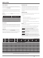 4
4
-
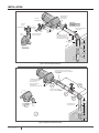 5
5
-
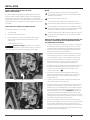 6
6
-
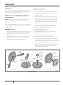 7
7
-
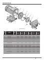 8
8
-
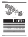 9
9
-
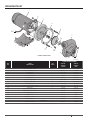 10
10
-
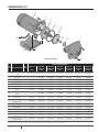 11
11
-
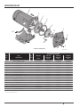 12
12
-
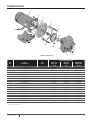 13
13
-
 14
14
-
 15
15
-
 16
16
-
 17
17
-
 18
18
-
 19
19
-
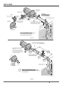 20
20
-
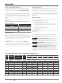 21
21
-
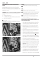 22
22
-
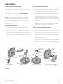 23
23
-
 24
24
-
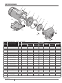 25
25
-
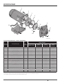 26
26
-
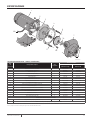 27
27
-
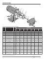 28
28
-
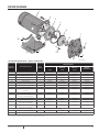 29
29
-
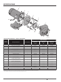 30
30
-
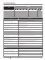 31
31
-
 32
32


STA-RITE J / JB Series 60 Cycle Centrifugal Pumps El manual del propietario
- Categoría
- Bombas de agua
- Tipo
- El manual del propietario
En otros idiomas
Documentos relacionados
-
STA-RITE DS2 Series Self-Priming Centrifugal Pump El manual del propietario
-
-
Pentair ProJet SN / HN Series El manual del propietario
-
Otros documentos
-
Flotec Simer Self-Priming Centrifugal Pumps El manual del propietario
-
-
Simer 2805E-01, 2806E-01, 2810E-01, 2815E-01 Convertible Deep Well Jet Pumps and Tank System El manual del propietario
-
MYERS MPB Series El manual del propietario
-
ITT GT07 Manual de usuario
-
Work-pro WPE 26N Manual de usuario