
Owner's Manual
Manual del Propietario
®
HEAT / COOL AIR CONDITIONER
EICALOR / REFRESCA ACONDICIONADOR
DE AIRE DE VENTANA
Model, Modelo 580.72187
Sears, Roebuck and Co., Hoffman Estates, IL 60179 U.S.A.
www.sears.com

TABLE OF CONTENTS ........................2
WARRANTY ..............................................2
SAFETY .....................................................3
Important Safety Instructions ...................... 3
ELECTRICAL REQUIREMENTS .......4
INSTALLATION ........................................5
Installation Requirements ......................... 5
Installation ................................................ 6
How to Install ............................................ 6
Removalfrom Window ................................. 8
OPERATION .............................................9
How and Why ........................................... 9
Normal Sounds ........................................ 9
Capacity and Running Time ..................... 9
Features ................................................. 10
Using the Air Conditioner ....................... 10
Display ................................................... 11
MAINTENANCE .....................................12
Air Filter Cleaning ................................... 12
Air Conditioner Cleaning ........................ 12
How to Replacethe Front Grille .................. 12
TROUBLESHOOTING .........................13
Before Calling for Service ...................... 13
ESPANOL ................................................14
MASTER PROTECTION
AGREEMENTS ........................................27
SERVICE NUMBERS ....... Back Cover
FULL ONE YEAR WARRANTY ON
ROOM AIR CONDITIONER
For one year from the date of purchase, when this
air conditioner is operated and maintained for
normal room cooling according to instructions in this
owner's manual, Sears will repair this air
conditioner, free of charge, if defective in material or
workmanship.
FULL FIVE-YEAR WARRANTY ON
SEALED REFRIGERATION SYSTEM
For five years from the date of purchase, when this
air conditioner is operated and maintained for
normal room cooling according to instructions in this
owner's manual, Sears will repair the sealed
refrigeration system (consisting of refrigerant,
connecting tubing, and compressor), free of charge,
if defective in material or workmanship.
WARRANTY SERVICE IS AVAILABLE BY
CONTACTING SEARS SERVICE AT
1-800-4-MY-HOME ®
Warranty coverage applies only to air conditioners
used for non-commercial, private household
purposes.
This warranty applies only while this product is in
use in the United States.
This warranty gives you specific legal rights, and
you may also have other right which vary from state
to state.
Sears, Roebuck and Co., D/817WA,
Hoffman Estates, IL 60179 U.S.A.
-2-

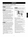
IMPORTANT SAFETY INSTRUCTIONS
The safety instructions below will tell you how to use your room air conditioner to avoid harm to yourself or
damage to your ROOM AIR CONDITIONER.
FOR YOUR SAFETY
Do not store or use gasoline or other flammable
vapors and liquids in the vicinity of this or any other
appliance. Read product labels for flammability and
other warnings.
PREVENT ACCIDENTS
To reduce the risk of fire, electrical shock, or injury
to persons when using your air conditioner, follow
basic precautions, including the following:
• Be sure the electrical service is adequate for the
model you have chosen.
• If the air conditioner is to be installed in a window,
you will probably want to clean both sides of the
glass first. If the window is a triple-track type with a
screen panel included, you may want to remove
the screen completely before installation.
• Be sure the air conditioner has been securely and
correctly installed according to the separate
installation instructions provided with this manual.
Save this manual and installation instructions for
possible future use in removing or reinstalling this
unit.
• Use gloves when handling the air conditioner.
Be careful to avoid cuts from sharp metal fins on
front and rear coils.
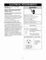
V.'_V_Vl:1:i_ll_[tlELECTRICAL INFORMATION
The complete electrical rating of your new room air
conditioner is stated on the serial plate. Refer to the
rating when checking the electrical requirements.
• Be sure the air conditioner is properly grounded.
To minimize shock and fire hazards, proper
grounding is important. The power cord is
equipped with a three-prong grounding plug for
protection against shock hazards.
• Your air conditioner must be plugged into a
properly grounded wall receptacle. If the wall
receptacle you intend to use is not adequately
grounded or protected by a time delay fuse or
circuit breaker, have a qualified electrician install
the proper receptacle.
• Do not run air conditioner with a protective
covering. This could result in mechanical damage
within the air conditioner.
• Do not use an extension cord or an adapter
plug.
_void fire hazard or electric shock.
Do not use an extension cord or an adapter plug.
Do not remove any prong from the power cord.
Grounding type
wall receptacl_ Do not under any
circumstances cut,
remove, or bypass
the grounding prong
from this plug.
Power supply cord _
with 3-prong _,
grounding plug _\
ENERGY SAVING IDEAS
• The capacity of the room air conditioner must fit
the room size for efficient and satisfactory
operation.
• install the room air conditioner on the shady side
of your home. A window that faces north is best
because it is shaded most of the day.
• Do not block air flow inside with blinds, curtains, or
furniture, or outside with shrubs, enclosures, or
other buildings.
• Close the floor and wall registers and the fireplace
damper so cool air does not escape up the
chimney and into the duct work.
• Keep blinds and drapes in other windows closed
during the sunniest part of the day.
• Clean the air filter as recommended in the
MAINTENANCE section of this manual.
• Proper insulation and weather stripping in your
home will help keep warm air out and cool air in.
• External house shading with trees, plants or
awnings will help reduce the air conditioner's work
load.
• Operate heat producing appliances such as
ranges, washers, dryers, and dishwashers during
the coolest part of the day.
-3-

OBSERVEALLLOCALCODESAND
ORDINANCES.
DONOT,UNDERANYCIRCUMSTANCES,
REMOVETHEPOWERSUPPLYCORD
GROUNDPRONG.
ELECTRICALGROUNDISREQUIREDON
THISAPPLIANCE.
A250-volt60Hz,AConly,20Afusedand
properlygroundedelectrical supply is required.
A time delay fuse or time delay circuit breaker
is recommended. Use a dedicated circuit,
serving only this appliance.
DO NOT USE AN EXTENSION CORD.
RECOMMENDED GROUNDING METHOD
For your personal safety, this appliance must
be grounded. This appliance has a power
supply cord with a 3-prong grounding plug. To
minimize possible shock hazard, the cord must
be plugged into a mating grounding type wall
receptacle and grounded in accordance with
the National Electrical Code (ANSt/NFPA 70)
latest edition and all local codes and
ordinances. If a mating wall receptacle is not
available, it is the personal responsibility and
obligation of the customer to have a properly
grounded 3-prong wall receptacle installed by a
qualified electrician.
Electrical Shock Hazard
Plug into a grounded 3 prong outlet.
Do not remove ground prong.
Do not use an adapter.
Do not use an extension cord.
Failure to follow these instructions can result
in death, fire, or electrical shock.
Line Cord Plug
" _/Do not, under any -"
_-_ circumstances, cut or
--- _ remove the grounding prong
_ from the plug.
Power supply cord with
3-prong grounding plug
Use Wall Receptacle Power Supply
Standard 250V,
3-wire grounding
receptacle rated
20A, 250V AC
Use 20 AMP,
time delay fuse
or circuit
breaker.
-4-

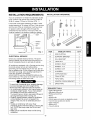
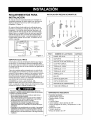
INSTALLATION REQUIREMENTS
Your air conditioner will install into standard double
hung windows with actual clear opening widths of
29 to 41 inches (737mm to 1041mm) (FIG. 1)
Lower sash must open sufficiently to allow a clear
vertical opening of 18 inches (457mm). Side louvers
and the rear of the air conditioner must have clear
air space to allow enough airflow through the
condenser for heat removal. The rear of the unit
must be outdoors, not inside a building or garage.
i-/- .... Sash
I
I _ Window
_'->.j Offset
Exterior
Interior wall "- .... ÷ FIG. 1
ELECTRICAL SERVICE
Check your available electrical service. The power
supply available must be the same as that shown on
the unit nameplate (found on right side of cabinet).
All models are equipped with a 3-prong service plug
to provide proper service and safe positive
grounding. Do not change plug in any way. Do not
use an adapter plug. If your present wall outlet does
not match your plug, call a qualified electrician to
make the necessary corrections.
SAVE CARTON and this OWNER'S MANUAL for
future reference. The carton is the best way to store
unit during winter or when not in use.
To avoid risk of personal injury, property damage,
or product damage due to the weight of this
device and sharp edges that may be exposed:
•Air conditioners covered inthis manual pose an
excessiveweight hazard. Two or more people
are needed to move and install the unit.
To prevent injury or strain, use proper lifting and
carrying techniques when moving unit.
• Carefully inspect locationwhere air conditioner
will be installed. Be sure itwill support the
weight of the unit over an extended period of
time.
• Handle airconditionerwith care.Wear
protective gloves whenever lifting or carrying the
unit. AVOID the sharp metal fins of front and
rear coils.
• Makesure air conditionerdoes not fall during
installation.
INSTALLATION HARDWARE
A B C D E
G H I J K
FIG.2
ITEM NAME OF PARTS Q'TY
A SIDE CURTAIN 2
B SUPPORT BRACKET 2
C SILL BRACKET 2
D LOCK NUT 4
E SCREW: 25/64" 11
F SCREW: 13/16" 7
G SCREW: 9/16" 5
H M-SCREW 2
I CARRIAGE BOLT 2
J FOAM STRIP 1
K FOAM SEAL 1
L WINDOW LOCKING BRACKET 1
M DRAIN PIPE 1
REQUIRED TOOLS:
Tight Fitting gloves
Standard screwdriver
Phillips screwdriver
Pliers
Sharp knife
3/8-inch open end wrench or adjustable wrench
1/4-inch hex socket and ratcher
Tape measure
Electric drill
ll4-inch drill bit
-5-

INSTALLATION
Pick a location which will allow you to blow the cold air
into the area you want. Windows used for installation
must be strong enough to support the weight of the air
conditioner. Good installation with special attention to the
proper position of the unit will iessen the chance that
service will be needed.
When cooling more than one room, installation location is
very important. If air conditioner is blocked by a storm
window frame, see step 16 on page 8 before beginning to
install. To cool your rooms, cold air must be blown from
the air conditioner in a straight path.
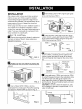
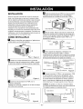
HOW TO INSTALL
D Remove the screws which fasten the cabinet at
the back and side of the unit. Save side screws.
Discard back screws.
FIG. 3
_'_ Slide the unit out of the cabinet by gripping the
base pan handle and pull forward while bracing the
cabinet.
FIG. 4
_E_J Cut the FOAM STRIP (ITEM J) to fit the
underside of the window sash. Peel off the backing
and attach the FOAM STRIP as shown in Fig. 5.
.... Sash
FIG. 5
D Insert the side curtain (ITEM A) into the upper guide
and lower guide of the air conditioner. Fasten the curtains
to the unit with screws (ITEM E).
Upperj g
FIG.6
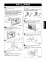
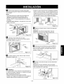
_4J Open the window. Mark a line on the center of the
window inner sill. Loosely attach the sill bracket (ITEM C)
to the support bracket (ITEM B) using the carriage bolt
(ITEM I) and the lock nut (ITEM D).
ITEM
B
ITEM I
r_ Attach the sill bracket to the window sill using the
screws (ITEM F). Carefully place the cabinet on the
window inner sill and align the center of the cabinet
front with the center line marked on the window inner
sill.
/Machine screw
Cabinet . /and locknut
trackhole j0uter
J edgeof
IT windowsill
Carriage bolt ................
\
and locknut Sill bracket FIG. 8
H Using an M-screw (ITEM H) and a lock nut (ITEM
D), attach the support bracket to the cabinet track hole.
Use the first track hole after the sill bracket on the
outer edge of the window sill. Tighten the carriage bolt
and the lock nut. Be sure the cabinet slants downward
1/4" from level (FIG. 9).
CAUTION: Do not drill a hole in the bottom pan. The
unit is designed to operate with approximately 1/2" of
water in bottom pan.
Lowerguide
INDOOR
Cabinet
OUTDOOR FIG. 9
-6-

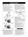
_J Pull the bottom window sash down behind the
upper guide until they meet.
NOTE:
• Do not pull the window sash down so tightly that the
movement of sliders is restricted. Attach the cabinet
to the window inner sill by driving the screws (ITEM F)
through the cabinet into window inner sill.
• The cabinet should be installed with a very slight tilt
downward to the outside 1/4" from level.
Window sash ;pper guide
\
Cabinet /
Frame curtain
FIG. 10
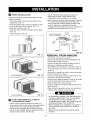
Q Expand side curtains to fill opening.
Attach each side curtain to the window sash using
2 screws (ITEM G). (FIG. 11)
FIG. 11
_'_ Attach the window locking bracket (ITEM L) with
a screw(ITEM G). See FIG. 12.
FIG. 12
[] DRAINAGE
A drain hole is provided at the rear of the air
conditioner unit. Select a drain method according to
the following.
• Remove the hole rubber from the base-pan.
• Connect a drain elbow of 9/16" inside diameter to
the drain pipe.
• Connect a drain hose of 9/16" inside diameter to the
drain elbow. (Drain hose is not supplied.)
FIG. 13
elbow elbow
[
hose
_"_ Slide the air conditioner into the cabinet. (FIG. 14)
CAUTION: For security purposes, reinstall side
screws that were removed in step 1.
Cord
Screw
Screw FIG. 14
]Cut the foam seal (ITEM K) to the proper length
and insert between the upper window sash and the
lower window sash. (FIG. 15)
FIG. 15
]Adjust the vent handle before the decorative
front is attached. (FIG. 16)
Straighten the lever, as shown. Pull down part @to
align with part _).
Part _B_
Part _A_
FIG. 16
-7-

[] FRONT INSTALLATION
install the front grille (packed separately) onto the
cabinet as follows:
• Hook upper tabs of front grille into slots on the
cabinet top. (FIG. 17)
• Push front grille's tips toward the cabinet in order
to snap side tabs into the cabinet. (FIG. 17)
• Open the inlet grille. (FIG. 18)
• Install the screw (ITEM E) through the front grille.
(FIG. 18)
• Close inlet grille. (FIG.19)
Front Installation FIG. 17
Front Installation FIG. 18
_!_ [_:_lj i [,] _1
Front installation FIG. 19
]IF AIR CONDITIONER IS BLOCKED BY
STORM WINDOW FRAME
• If storm window presents interference, fasten a 2"
wide wood strip to the inner window sill across the full
width of the sill. The wood strip should be thick
enough to raise the height of the window sill so that
the unit can be installed without interference from the
the storm window frame. See FIG. 20.
Top of wood strip should be approximately 3/4"
higher than the storm window frame to help
condensation to drain properly to the outside.
• Install a second wood strip (approximately 6" long by
11/2" wide and same thickness as first strip) in the
center of the outer sill flush against the back of the
inner sill. Screw the L brackets into this strip.
To support the lower guide, screw an "L" bracket (not
supplied) into this strip as shown in FIG. 20.
1 1/2"min.
WOODSTRIPMOUNTED (38mm)
ON TOPOFINNERSILL _="1 I"= 3/4" ±
""_ _ I CLEARANCE,
TO%*
INNER ILBRACKET/ L FRAME
SEE
I I OUTER
L_ I sILL
INSIDE I I OUTSIDE
FIG. 20
REMOVAL FROM WINDOW
• Turn off and unplug the air conditioner.
• Remove the front grille. See HOW TO REMOVE THE
FRONT GRILLE. Refer to page !2.
• Unscrew the side screws that you installed in Step 12.
• Slide the air conditioner out of the cabinet.
BE CAREFUL NOT TO DROP iT. Hold onto it firmly the
whole way sliding it out. Once removed, set it safety out
of the way.
• Remove the L bracket from window frame and the sash
seal from between the windows.
• Unscrew the side curtains from the window frame. Fold
them back to the sides of the cabinet.
• Remove screws attaching cabinet to inner sill. Be careful
not to let cabinet fall once screws are removed.
• Remove cabinet from window opening.
• Place air conditioner into cabinet. Reinstall side screws
and Front GriIle.
• Place unit and all assembly hardware in air conditioner
shipping carton, and store in clean, dry place.
•Air conditioners coveredinthis manual pose an
excessive weight hazard. Two or more people
are needed to move and install the unit.
To prevent injuryor strain, use proper lifting and
carrying techniques when moving unit.
•When handling the airconditioner, be carefulto
avoid cuts from sharp metal fins on front and
rear coils.
•Make sure airconditionerdoes notfall during
removal.
-8-

HOW AND WHY
Your room air conditioner provides the following
functions to make hot weather living more
comfortable:
• Cools and circulates room air.
• Lowers humidity by removing excess moisture.
• Filters out summertime dust, dirt, and some
airborne impurities.
The air conditioner performs these functions by
drawing room air through a filter which traps dust
and dirt particles. The air then passes over a
cooling coil which refrigerates the air and removes
excess moisture. The same air is then returned to
the room- cooler, drier, and cleaner. Moisture
removed from the room air is carried to the outside
and evaporated.
Your air conditioner is designed to be easy to
operate and to provide plenty of cooling power.
NORMAL SOUNDS Fie.21
Aside from the regular fan motor and compressor
sounds coming from your air conditioner, you will
once in a while hear a pinging sound. This is the
result of moisture being picked up from the air in the
room and thrown against the air conditioner's fan.
This is normal and should not be cause for concern.
Also, do not be alarmed if you hear a slight hissing
or gurgling sound coming from your air conditioner
after it is off. These are normal coolant noises.
CAPACITY AND RUNNING TIME
Proper unit size is important in deciding the desired
comfort for the area you want to cool. The proper
size is determined by the number of square feet in
the area to be cooled.
Whenever the heat or humidity load is above normal
the air conditioner must run longer and more often
to keep the desired temperature you have selected,
Under heavy heat load conditions the air conditioner
may need to run constantly to keep the temperature
you want.
At times using the HIGH FAN setting to circulate the
room air may make it comfortable even though you
do not have the air conditioner set to cool the air.
This will decrease your cost of use.
Fan
You may hear air
movement from the
fan.
Unit Vibration
The unit may vibrate
and make noise
because of poor wall
or window
construction.
Compressor
The modern high
efficiency compressor
may have a high
pitched hum or
pulsating noise that
cycles on and off.
Condenser
You may hear
droplets of water
hitting the condenser,
causing a pinging or
clicking sound.
FIG. 21
WATER DRAIN VALVE
When the outside temperature drops below 58°F
and the unit is set for heating, a drain valve opens
up to release water from the base pan. This is
normal and prevents water from freezing in the base
pan and interfering with the outdoor fan.
-9-

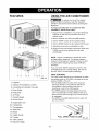
FEATURES
1 15 4 6 5 73 214
17 9 16 8
11 12 10 13
FIG. 22
1. Cabinet
2. Vertical Air Direction Louvers
3. Horizontal Air direction Louvers
4. Front Grille
5. Inlet Grille
6. Air Filter
7. Control Board
8. Power Cord
9. Evaporator Coil
10. Condenser
11. Compressor
12. Base Pan
13. Brace
14. Upper Guide
15. Curtain
16. Vent Control
17. Electric Heater
USING THE AIR CONDITIONER
_To reduce the risk of fire, electric
shock, or injury to persons, read the important
SAFETY instructions section before operating this
appliance
To begin operating the air conditioner after
installation, follow these steps:
1. Plug in the air conditioner. (To prevent electrical
hazards, do not use an extension cord or an
adapter plug.)
2. Set the exhaust vent to the CLOSE position.
3. Set the TEMP Control to the coolest setting.
4. Set the MODE Control at the highest COOL level.
5. Adjust the louvers for comfortable air flow.
6. Once the room has cooled, adjust the TEMP and
MODE control to the setting you find most
comfortable.
NOTE : If the air conditioner is turned off, wait 3
minutes before restarting. This allows pressure
inside the compressor to equalize. Failure to wait 3
minutes before restarting may cause inefficient
operation.
If you move the TEMP Control to a warmer, then
immediately back to a cooler setting, the unit will
shut off. Wait 3 minutes before restarting.
VENT CONTROL
The Vent Control allows the air conditioner to either
recirculate inside air (CLOSE) or exhaust air to the
outside (OPEN). (FIG. 23)
• The CLOSE position is used when maximum
cooling is desired. It may also be used for air
recirculation without cooling when the air
conditioner is set in the FAN position.
• The OPEN position removes stale air from the
room and exhausts it to the outside. Fresh air is
drawn into the room through your home's normal
air passages.
• The OPEN or CLOSE position can be used with
any fan selection.
PULL
FIG. 23
-10-

AIR CONDITIONER FEATURES
The controls featured in this manual are representative of the many models available.
Your model may look slightly different.
OFF ON
Auto Swing
Turn off Auto Swing
When0perafi0rl Switch is off
OFF
FAN FAN
ONLY T%ONL
'i LOW
i COOL
HIGH
HEAT COOL
TEMP MODE
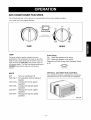
TEMP
The temp control is used to maintain the room
temperature. The compressor will cycle on and off to
keep the room at the same level of comfort. Turn the
knob clockwise to COOLER (blue) and the indoor air
will become cooler. Turn the knob counterclockwise to
WARMER (red) and the indoor air will become
warmer.
Auto Swing
ON : Starts the operation of air swing.
OFF :Stops the operation of air swing.
Please turn off Auto Swingwhen Operation Switch
is off.
On
Auto Swing
MODE
OFF :Turns air conditioner off.
FAN ONLY : Fan operation without cooling or
heating.
LOWCOOL : Cooling with low fan speed
operation.
HIGHCOOL : Cooling with high fan speed
operation.
LOWHEAT : Heating with low fan speed
operation.
HIGHHEAT : Heating with high fan speed
operation.
VERTICAL AIR DIRECTION CONTROL
The vertical air direction is adjusted by moving the
horizontal louvers up or down with your fingertips.
FIG. 24
-11 -

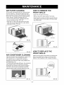
AIR FILTER CLEANING
The Air Filter will become dirty as it removes dust
from the inside air. It should be washed at least
every 2 weeks. If the Air Filter remains full of dust,
the air flow will decrease and the cooling capacity
will be reduced, possibly damaging the unit.
• Pull the inlet grille forward, grasping both tabs,
then pull out the air filter. (FIG. 25)
• Wash the Air Filter under the faucet with warm
water. Be sure to shake off all the water before
replacing the filter. (FIG. 26)
FIG. 25
FIG. 26
AIR CONDITIONER CLEANING
Clean the front grille and inlet grille by wiping with a
cloth dampened in a mild detergent solution.
The cabinet may be washed with mild soap or
detergent and lukewarm water, then polished with
liquid appliance wax.
To ensure continued peak efficiency, the condenser
coils (outdoor side of unit) should be checked
periodically and cleaned if they become clogged
with soot or dirt from the atmosphere. Brush or
vacuum exterior coils to remove debris from fins.
FIG. 27
HOW TO REMOVE THE
FRONT GRILLE
• Open the inlet grille downward.
• Remove the screw securing the Front Grille.
• Push the grille up from the bottom and pull the top
of the grille away from the case to lift the top tabs
out of their slots.
Inlet Grille
HOW TO REPLACE THE
FRONT GRILLE
Attach the front grille to the cabinet by inserting the
tabs on the grille into the slots on the front of the
cabinet. Push the grille in until it snaps into place.
FIG. 29
12

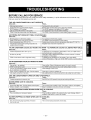
BEFORE CALLING FOR SERVICE
Check the following list to be sure a service call is really necessary. A quick reference to this manual may
help you avoid an unneeded service call.
THE AIR CONDITIONER WILL NOT OPERATE
Check if...
Wal! plug disconnected.
House fuse blown or circuit breaker tripped.
MODE selector is OFF position.
Unit was turned offand then ontoo quickly.
TEMP Control set warmer than room temperature.
Then...
Push plug firmly intowall outlet.
Replacefuse with time delay type or resetcircuit breaker.
Turn MODE selector to thedesired COOL setting.
Turn unit off andwait 3 minutes before restarting.
Turn TEMP Control clockwise to acooler setting(higher number).
AIR FROM UNIT DOES NOT FEEL COLD ENOUGH.
Check if... Then...
MODE selector in LOW COOL position. Turn selector to HIGHCOOL position
TEMP Control set toowarm (lower number). TurnTEMP Control clockwise to acooler setting.
Room temperature below 70°F (21°C). Cooling may not occur until roomtemperature risesabove 70°F (21°C).
Temperature sensing tube touchingevaporator coil, Straightentube away from evaporator coil.
located behindfront grille.
THE AIR CONDITIONER COOLING, BUT ROOM IS TOO WARM - ICE FORMING ON COOLING COIL BEHIND FRONT GRILLE.
Check if... Then...
Outdoor temperature below 70°F (21_'C). To defrost the coil,setselector to FAN position. Then, turn TEMP control
counterclockwise to awamler setting.
Airfilter may bedirty. Clean filter. Refer to Maintenance section of owner's manual. To defrost,
set selector to FAN position.
TEMP Control set too coldfor night-time cooling. To defrostthecoil,set selectortoa FANposition.Then,settheMODE
controlatFANpositionor "HighCool"withtheTEMPcontroltoa warmerposition.
THEAIR CONDITIONERCOOLING,BUT ROOMIS TOOWARM.
Check if...
Dirty airfilter - air restricted. Clean air filter. Refer toMaintenance section of owner's manual.
TEMP Control set too warn1. Turn TEMP control clockwise to a cooler setting (highernumber).
Front of unit is blocked by drapes, blinds, furniture, Clearblockage infront of unit.
etc. Airdistribution is restricted.
Doors,windows, registers,etc. open. Cold air escapes. Closedoors, windows, registers, etc.
Unit recently turned on inhotroom. Allowadditionaltimetoremovestoredheatfromwails,ceiling,floor,andfurniture.
THE AIR CONDITIONER TURNS ON AND OFF RAPIDLY.
Check if... Then...
I Outside temperature is extremely hot. I Set MODE on HIGHspeed to bringairpast cooling coilsfaster.
NOISE WHEN UNIT IS COOLING.
Check if... Then...
Soundoffanhittingwater- fromthemoistureremovalsystem. [ This is nomlal when humidity is high.Close doors, windows,and registers.
Window vibration - poor installation. [ Refer to installation instructionsor checkwith installer.
WATER DRIPPING INSIDE ROOM WHEN UNIT IS COOLING.
Check if... Then...
The air conditioner is improperly installed. Tilt airconditioner slightly tothe outsideto allowwater drainage. Refer to
installation instructions or check with installer.
WATER DRIPPING OUTSIDE WHEN UNIT IS COOLING.
Check if... Then...
The unit is removing large quantities of moisture This is normalduring excessively humid days.
from humid room.
-13-

INDICE DE MATERIAS ............................. 14
GARANTiA ................................................ 14
SEGURIDAD .............................................. 15
Importantesinstrucciones de seguridad .....15
REQUERIMIENTOS ELI_CTRICOS ......... 16
INSTALACION ........................................... 17
Requerimientos para instalaci6n .......... 17
Installaci6n ............................................ 18
C6mo instalado ..................................... 18
La eliminaci6n de la ventana ................. 20
OPERACION .............................................. 21
C6mo y por que ..................................... 21
Sonidos normales .................................. 21
Capacidad y tiempo de funcionamiento ---21
Caracteristicas ..................................... 22
Uso del equipo de aire acondicionado--22
Despliegue ............................................ 23
MANTENIMIENTO .................................... 24
Limpieza del filtro del aire ...................... 24
Limpiezadel equipodeaire acondicionado....24
C6mo a reemplaza el grille anterior ......24
CORRECCION DE FALLAS ...................... 25
Antesde LlamarparaServicio...................... 25
ACUERDOS DE PROTECCION
ESPECIALIZADA ...................................... 27
PARA PEDIR SERVlClO----Cubierta Trasera
GARANTIA DE UN ANO POR EL
EQUlPO DE A!RE ACONDIClONADO
DE HABITAClON
Durante un aSo completo a partir de la fecha de
compra, si este equipo de aire acondicionado recibe
mantenimiento y se utiliza para el enfriamiento
normal de habitaci6n seg_n las instrucciones
indicadas en este manual del propietario, Sears
reparar& gratuitamente este equipo de aire
acondicionado, si tiene algQn defecto en materiales
o fabricaci6n.
GARANTiA TOTAL DE ClNCO ANOS
POR EL SISTEMA DE REFRIGERACION
HERMETICAMENTE SELLADO
Durante cinco aSos a partir de la fecha de compra,
si este equipo de aire acondicionado recibe
mantenimiento y se utiliza para el enfriamiento
normal de habitacion segQn las instrucciones
indicadas en este manual del propietario, Sears
reparar& gratuitamente el sistema de refrigeracion
hermeticamente sellado (que consiste en el agente
refrigerante, los tubos de conexion y el compresor),
si tiene algQn defecto en materiales o fabricacion.
EL SERVIClO DE GARANTiA ESTA A SU
DISPOSICION CON SOLO PONERSE EN
CONTACTO EL CENTRO DE SEARS AL
1-800-4-MY-HOME _
La proteccion de garantia cubre unicamente a
los equipos de aire acondicionado usados para
uso domestico y no para uso comercial.
Esta garantia s61otiene validez mientras el
producto se este usando en los Estados
Unidos.
Esta garantia le da derechos legales
especificos y usted puede tener otros
derechos que varian de estado en estado.
Sears, Roebuck and Co., D/817WA,
Hoffman Estates, IL 60179 U.S.A.
-14-

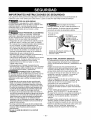
IMPORTANTES INSTRUCCIONES DE SEGURIDAD
Las siguientes instrucciones de seguridad le indicaran como usar su equipo de aire acondicionado de
habitacion para evitar daSos para usted mismo y para su EQUIPO DE AIRE ACONDICIONADO.
['Y.'_J_vt_;ll_[_[ilPOR SU SEGURIDAD
No almacene ni use gasolina u otros vapores y
liquidos inflamables cerca de este o cualquier otro
electrodomestico. Lea las etiquetas de los
productos para ver si contienen advertencias sobre
el car&cter inflamable de los mismos y otras
advertencias.
V'_ PARA PREVENIR ACCIDENTES
Para reducir el riesgo de incendios, descargas
electricas o lesiones personales al usar su equipo
de aire acondicionado, tome las precauciones
b&sicas, entre las que est&n las siguientes:
• Asegurese de que la alimentaci6n electrica sea la
apropiada para el modelo que usted ha elegido.
• Si el equipo de aire acondicionado debe instalarse
en una ventana, a usted probablemente le
conviene limpiar primero ambos lados del vidrio.
Si la ventana es del tipo de tres paneles con un
panel incluido de pantalla, le conviene sacar la
ventana completamente antes de la instalacion.
• AsegQrese de que el equipo de aire
acondicionado ha sido instalado correctamente y
con seguridad segQn se seSala en las
instrucciones separadas de instalaci6n que vienen
en este manual. Conserve este manual y las
instrucciones de instalacion para usarlos
posiblemente en el futuro al sacar o volver a
instalar esta unidad.
• Utilice guantes al manejar el equipo de aire
acondicionado, tenga cuidado para evitar cortadas
con las afiladas aletas metalicas que se hallan en
los serpentines frontales y posteriores.
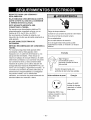
INFORMACION ELECTRICA
En la placa de serie del fabricante se indica cu&l es
la capacidad electrica nominal completa de su nuevo
equipo de aire acondicionado para habitaci6n. Consulte
esta placa cuando vaya a verificar los requerimientos
electricos.
• Asegurese de que el equipo de aire acondicionado
tenga una conexion correcta a tierra. Para reducir al
minimo los riesgos de descargas electricas e incendio,
es importante conectar el equipo correctamente a tierra.
El cord6n de alimentaci6n electrica est,1 equipado con
un enchufe de tres espigas con conexi6n a tierra para
protegerle contra riesgos de descargas electricas.
• Su equipo de aire acondicionado debe enchufarse en
una toma de corriente de pared que tenga una conexi6n
correcta a tierra. Si la toma de corriente de pared que
usted piensa usar no est,1 conectada correctamente a
tierra o no estEi protegida con un fusible de acci6n
retardada o con un interruptor de circuito, haga que un
electricista calificado le instale la toma de corriente de
pared en forma correcta.
• No ponga a funcionar el equipo de aire acondicionado
con una cubierta protectora exterior encima. Esto podria
ocasionar daSos mecEinicos dentro del aire
acondicionado.
• No use un cable de extensiSn ni un enchufe
adaptador,
_ Evite los peligros de incendios y
descargas electricas. No use un cable de extension ni un
enchufe adaptador. No elimine ninguna de las espigas
del enchufe dei cord6n de alimentaci6n electrica.
Toma de corriente
de pared con
conexi6n a tierra. una 1
circunstancia corte,
extraiga o intente /
eliminar la espiga de
conexion a tierra de este_
enchufe. J
Cord6n de alimentaci6n electrica con _
enchufe de tres espigas con
conexi6n a tierra.
IDEAS PARA AHORRAR ENERGiA
• La capacidad del equipo de aire acondicionado
debe corresponder al tama_o de la habitation
para el funcionamiento eficiente y satisfactorio del
equipo.
• Instale el equipo de aire acondicionado de
habitaci6n en el lado sombreado de su hogar. Una
ventana orientada hacia el norte es la mejor
porque tiene sombra la mayor parte del dia.
• No bloquee el flujo de aire hacia el interior con
persianas, cortinas o muebles; o la parte de
afuera con arbustos, paredes u otras
construcciones.
• Cierre el regulador de tiro de la chimenea, las
rejillas de calefacci6n del piso y la pared, de tal
modo que el aire frio no se escape ni por la
chimenea ni por los conductos.
• Mantenga las persianas y las cortinas de otras
ventanas cerradas durante la parte mas soleada
del dia.
• Limpie el filtro del aire como se recomienda en la
secci6n "MANTENIMIENTO" de este manual.
• El aislamiento correcto y las juntas hermcticas en
puertas y ventanas en su hogar le ayudaran a
mantener el aire caliente afuera y el aire frio
adentro.
• AI darle sombra externamente a la casa con
arboles, plantas o toldos ayudara a reducir la
carga de trabajo del equipo de aire acondicionado.
• Opere los aparatos que producen calor como, por
ejemplo, hornos, lavadoras, secadoras y
lavaplatos durante la parte mas fria del dia.
-15-

RESPETE TODOS LOS CODIGOS Y
REGLAMENTOS.
BAJO NINGUNA CIRCUNSTANCIA CORTE,
QUITE O EVITE EL USO DE LA CONEXION
A TIERRA DE ESTA CLAVIJA.
ESTE APARATO NECESITA SER
CONECTADO A TIERRA.
Se requiere una alimentacion electrica CA,
adecuadamente conectada a tierra con un
fusible de 20 A, de 60 Hz y de 250 V.
Se recomienda un fusible de retardo o un
disyuntor de circuito que alimente solamente a
este aparato.
NO USE CABLE ELC:CTRICO DE
EXTENSION.
MI_TODO RECOMENDADO DE CONEXlON A
TIERRA
Por su propia seguridad este aparato debe
conectarse a tierra. Este aparato viene
equipado con un cable de alimentaci6n y una
clavija de tres terminales. Para reducir al
maximo el peligro de choque electrico, el cable
debe estar conectado a una conexi6n de pared
con conexi6n a tierra, y esta conexi6n debe
hacerse de acuerdo con la Qltima edici6n del
C6digo Electrico Nacional (ANSI/NFPA 70), asi
como con los c6digos y reglamentos locales. Si
no existe una conexi6n de pared adecuada, el
cliente tiene la responsabilidad y la obligaci6n
de mandar instalar, con un electricista
calificado, una conexi6n de pared adecuada de
tres terminales con conexi6n a tierra.
Peligrodechoqueelectrico
Conecteen unaconexi6nde pared de3 terminales
Noquitela terminalde conexi6na tierra
Nouseadaptadores
Nousecableelectricode extensi6n
Si no sesiguenestasinstrucciones,puede
ocasionarsela muerte,un incendioo un choque
electrico.
Enchu_
f Bajo Ninguna
I circunstancia corte o
_bf remueva el salida de tierra
del enchufe
Cordon tomacomente con
enchufe de tierra de tres salidas.
Utilicerecibidoresdepared Energia
Estandar 250V, tres
cables receptor a tierra
20A, 250V AC
nominal.
Utilice 20 AMP,
fusible de tiempo
retardado o fusible
Interruptor.
-16-

REQUERIMIENTOS PARA
INSTALAClON
Su equipo de aire acondicionado se instalar& en
ventanas est&ndar de doble panel con anchos de
abertura libre de 737 mm a 1041 mm (29 a 41
pulgadas). (Figura 1)
El marco inferior debe abrirse Io suficiente para
permitir una abertura vertical libre de 457 mm (18
pulgadas). Las rejillas desviadoras laterales y la
parte posterior del equipo de aire acondicionado
deben tener un espacio libre de aire para permitir
suficiente flujo de aire a traves del condensador
para asi eliminar el calor. La parte posterior de la
unidad debe quedar al aire libre, no dentro de un
edificio o garaje.
Banda
Pared interior'- .... ° Figura 1
SERVIClO ELECTRICO
Compruebe cual es la alimentacion electrica que Ilega a
su domicilio. La alimentaci6n electrica disponible debe
ser la misma que se muestra en la placa del fabricante de
la unidad (que se halla en el lade derecho deI gabinete de
corriente altema).
Todos los modelos estan equipados con un enchufe de
tres espigas para suministrar un servicio correcto y una
conexion a tierra segura y positiva. No cambie el enchufe
de ninguna forma. No use un enchufe adaptador. Si su
toma de corriente de pared actual no puede usarse con el
enchufe del equipo, Ilame a un electricista catificado para
que efectQe las correcciones necesarias.
CONSERVE LA CAJA y este MANUAL DEL
PROPIETARIO para que le sirva come referencia en el
futuro. La caja es la mejor manera de conservar la unidad
durante el invierno o cuando no esta en uso.
INSTALACION PIEZAS DE MONTAJE
A B C D E
F G H I J K
Figura 2
iTEM NOMBRE DE LAS PIEZAS CANTIDAD
A PANEL DE GUiA 2
B SOPORTE 2
C SOPORTE DE ANTEPECHO 2
D CONTRATUERCA 4
E TORNILLO: 25/64" 11
F TORNILLO: 1 3/I6" 7
G TORNILLO: 9/16" 5
H TORNILLO M 2
I BULON 2
J ClNTA DE ESPUMA 1
K ClNTA DE ESPUMA 1
L SOPORTE DE CERRADURA 1
M TUBO DE DRENAJE 1
HERRAMIENTAS REQUERIDAS
Para evitar el riesgo de lesiones personales, danes a su
propiedad, o danos al producto debido al peso de este equipo
y los fiIosa que seran expuestos:
• El aire acondicionado del que se habtaen este manuaI
afirma peIigro de peso excesivo.
Dos o mas personas se requiere para mover e instalar Ia
unidad. Para evitar heridas o agotamIento, use tecnicas
apropiadas para levntar y mover la unidad.
• Cuidadosamente inspeccione el lugar donde elaire
acondicionado sera puesto. Asegurese que etlugar
sostenga el peso de Ia unidad sobre unperiodo de tiempo
protongado.
• Mantenga su aire acondicionado con cuidado. Use guantes
protectores cuando levante o mueva Ia unidad. EVlTE las
aletas filosas de metal en eIserpentin delantero y de atras.
• Asegurese que el aire acondicionado no se caiga durante ta
instaIacion.
• Guantes apretados
• Destornillador normal
• Destornillador Phillips
• Pinsas
• Cuchillo filoso
• Llave inglesa o Ilave abierta de 3/8"
• Llave hexagonal de cubo y trinquete de 1/4 de
pulgada
• Cinta para medir
• Taladro electrico
• Broca de taladro de 1/4"

INSTALACION
Escoja un lugar que le permJta Ilevar el aire frio al area que
desea. Las ventanas que se usen para la Jnstalacion deben
tener la resJstencia suficJente para soportar el peso del equJpo
de aJreacondicionado. Una buena instalaci6n con atenci6n
especial a la correcta posicion de la unidad disminuJra la
probabilidad de que sea necesario efectuar reparaciones.
Cuando se desea enfrJar mas de una habitacion, la
instalaci6n es muy importante si el aire acondicionado esta
bloquedo por un marco de la contraventana yea el paso 16 en
la pagina 8 antes de comenzar la instalacion. Para enffiar sus
habitaciones, el aJrefrio debe desplazarse desde el equipo de
aire acondicJonado en una trayectorJa recta.
COMO INSTALARLO
H Saque los tornillos que aseguran el gabinete en
ambos lados yen la parte posterior.
Figura 3
I_ Deslice la unidad sacandola de su gabinete
agarrando el asa del recipiente de la base y tirando
de ella hacia delante mientras sostiene el gabinete.
Figura 4
I[I_ Corte la cinta de espuma (iTEM J) a la
extension apropiada.
Despegue el refuerzo y peguelo en el lado de abajo
del marco de la ventana.
......Banda
Figura 5
D Inserte los panetes de guia (iTEM A) en Ia guia superior
y las guias de marco det equipo de aire acondicionado.
Sujete las cortinas en la unidad con los tomillos (iTEM E)
iTEM E
Guia mas baja EFigura 6
I_ Abra la ventana. Marque una linea en el centro de la
repisa de la ventana entre los moldes de tope lateral de Ia
ventana. Fije sin apretar el soporte de antepecho (iTEM C)
al otro soporte (iTEM B) usando el bulon (iTEM I) y la
contratuerca (iTEM D).
iTEM I
"'_iTEM D
Figura 7
r_Fije el soporte de antepecho al antepecho a la
ventana usando los tornillos (iTEM F). Coloque
cuidadosamente el gabinete sobre la repisa de la ventana
y aIinee la marca del centro en la parte frontal inferior con
la linea central marcada en la repisa de la ventana.
para metales y
Orificio de --
exterior deI
la
ventana
(iTEM F)
Bulon y contratuerca
Soporte de antepecho Figura 8
W Usando el tornilIo M (iTEM H) y la contratuerca (iTEM
D), fije et soporte al orificio de carriI deI gabinete. Use et
primer orificio de carriI despues det soporte de antepecho
en el borde exterior del antepecho de ventana. Apriete el
bulon y Ia contratuerca. AsegQrese de que el gabinete se
incline hacia fuera 114de gota usando el niveI. (Figura 9)
CUIDADO: No perfore un orificio en el recipiente inferior.
La unidad esta dise_ada para operar con aproximadamente
112puIgada de agua en et recipiente inferior.
Guia inferior _
INTERIOR
GabJnete
EXTERIOR
Figura 9
-18-

_Tire del marco inferior de la ventana hacia abajo
detras de la guia superior hasta que se encuentre ia guia
con el marco.
NOTA:
• No tire del marco de la ventana tan hacia abajo que
restrinja el movimiento de las correderas. Fije el
gabinete a la repisa de la ventana atornillando los
tornillos (ITEM F) a traves del gabinete en la repisa de
ia ventana.
• El gabinete debe instalarse 1/4 de gota de el nivei, hecia
abajo y hacia fuera.
Marco de Barra fijadora superior
la
ventana/,__-_
JTEGM_ I _
_ iTEMF Figura 10
D Extienda el panel hasta llenar el hueco.
Fije cada panel guia en el marco de la ventana usando
dos tornilios (iTEM G). (Figura 1! )
iTEM G
lower Guide Figura 11
_'_Se debe instalar el asa antes de fijar el frente
decorativo. (Figura 12)
iTEM G
Figura t2
_q_l DREANJ E
En la parte posterior de la unidad de aire acondicionado hay
un orificio de drenaje. Selecoione un metodo de drenaje
segQn las siguientes instrucoiones:
• Saque del recipiente de base la goma del orificio.
• Conecte una manguera de drenaje de 9/16" de pulgada de
diametro intemo a! tubo de drenaje como se muestra.
• Conecte un codo de tubo de 9/16" de pulgada de diametro
interno al tubo de drenaje, conecte seguidamente una
manguera de drenaje de 9/16" de pulgada de diametro
interno al codo del tubo como se muestra. (El equipo de aire
acondicionado no viene con una manguera de drenaje.)
]u odeL T ode
renaje drenaje
Manguera I_1
de drenaje Manguera de drenaje
Figura 13
_'-_ Deslice el chasis hacia el interior del gabinete.
(Figura 14)
CUIDADO: Con fines de seguridad, vuelva a
instalar los tornillos en los lados del gabinete.
alimentaci6n
Tornillo el_ctrica
TornilIo Figura 14
_J Corte la junta hermetica de espuma(JTEM K)
para que tenga la Iongitud apropiada e insertela
entre el marco superior y el marco inferior de la
ventana. (Figura 15)
Figura 15
_]J Ajuste el asa antes de fijar el frente decorativo.
(Figura 15)
Enderence el kit de ventilacion como se indica,
halando hacia debajo de la parte (_) Ilevandola en la
linea horizontal con la parte _}).
Parte (_
Parte@ Figura 16
-19-

[] INSTALACION FRONTAL
Instale la rejilla frontal con el gabinete de la
siguiente manera:
• Tire de la rejilla frontal hacia abajo desde la parte
superior del gabinete. (Figura 17)
• Empuje las puntas de la rejilla frontal hacia el
gabinete para insertar las leng etas de la rejilla
dentro del gabinete. (Figura 17)
• Abra la rejilla de entrada. (Figura 18)
• Apriete el tornillo (iTEM E) a traves de la rejilla
frontal fijandolo al recipiente de base (Figura 18)
• Cierre la rejilla de entrada. (Figura 19)
Figura 17
Instalaci6n frontal Figura 18
I r!_ [*_lJlJ7-'lJI*]
Instalacion frontal
Figura 19
]SI EL ACONDIClONADOR DE AIRE ESTA BLOQUEADO
POR EL MARCO DE LA CONTRAVENTANA
• Si la contraventana interfiere, fije un liston de madera de
2" de ancho al alfeizar interior de la ventana, que
atraviese la anchura total del alfeizar. El liston de
madera debe ser suficientemente grueso para levantar
la altura del alfeizar de la ventana de tal manera que la
unidad pueda ser instalada sin la interferencia dei marco
de la contraventana. Vea Ia Figura 20.
La parte superior del liston de madera debe ser
aproximadamente 3/4" mas alto que el marco de la
contraventana o el list6n de madera (fuera de la casa)
para que el vapor emanado de Ia unidad pueda drenar
adecuadamente hacia eI exterior.
• Instale un segundo Iistsn de madera (de aproximadamente
6" de largo y 1" de ancho y del mismo grosor deI primer
liston) en el centro det alfeizar exterior nivetado con ta
parte posterior det alfeizar interior. Atomille los soportes L
entre Ia faja. Esto tevantara et soporte L como se muestra
en la Figura 20.
1 1/2"min.
(38mm)
FRANJA DE MADER_..._. /-.._- 3_4-PULG
MONTADA SOBRE DE SEPARACION
LA PARTE SUPERIO
DEL DESCANSO
INTERIOR _"I___I'ENTANA DE
SUPPORT HOJA DOBLE
ANTEPECHO EN L
INTERIOR TIRA DE MADERA
PARA LA MENSULA
L Y MENSULA DE
ANTEPECHO ANTEPECHO
ERIOR
Figura 20
La ELIMINACION DE la VENTANA
• Apague el acondicionador aereo
• Quite el grilIe anterior Yea COMO A REEMPLAZA EL GRILLE
ANTERIOR. Refierase a pagina 34
• Destornille el tomilIo del tado que usted instal6 en el Paso 12.
• Deslice el acondicionador aereo fuera dei gabinete. TENGA
CUIDADO no A la GOTA. Tenga en Iofirmemente la manera
entera que desliza fuera. Una vez quitado, Iopuso seguridad
fuera de ta manera.
• Quite el parentesis Ldel marco de ventana y el seflo de banda
de entre el windows.
• Destomille las cortinas deI lado del marco de ventana.
Doblelos apoyan a los lados det gabinete.
• Quiteel tomilloconectargabineteal alfeizatinterior.Tengaeuidado
no apermitioquegabinetefallara unaveztomillosse quitan.
• Quite gabinete de abrir de ventana.
• Coloque el acondicionador aereo en et gabinete. Vuelva a
instalar los tomillos del lado y Grille Anterior.
• Coloque la unidad y toda ferreteria de la asamblea en el
carton aereo del envio dei acondicionador, yen la tienda en
limpia, seca el lugar.
• El aire acondicionado del que se habla en este
manual afirma peligro de peso excesivo.
Dos o mas personas se requiere para mover e
instalar la unidad. Para evitar heridas o
agotamlento, use tecnicas apropiadas para
levntar y mover la unidad.
• AI manejar la unidad, tenga cuidado para evitar
cortarse con las alertas met&licas afiladas que
est&n en los serpentines frontal y posterior.
• Asegurese que el aire acondicionado no se
caiga durante la instalacion.
- 20 -

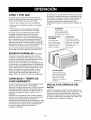
COMO Y POR QUI
Su equipo de aire acondicionado de habitacion
brinda las siguientes funciones para hacer que la
vida en climas c&lidos sea mas confortable:
• Enfria y hace circular el aire por la habitacion
• Disminuye la humedad eliminando la humedad
excesiva.
• Filtra el polvo, el sucio y algunas impurezas
transportadas en el aire del clima veraniego.
El equipo de aire acondicionado realiza estas
funciones haciendo pasar el aire del medio
ambiente a traves de un filtro que atrapa las
particulas de polvo y sucio. El aire pasa entonces
por un serpentin de enfriamiento que refrigera el
aire y elimina el exceso de humedad. El mismo aire
regresa entonces al enfriador, secador y limpiador
del aire del ambiente. La humedad extraida del aire
ambiente es Ilevada al exterior y evaporada.
Su aire acondicionado est& diseSado para operar y
suministrar una enorme potencia de enfriamiento.
SONIDOS NORMALES Figura 21
Adem_is de los sonidos regulares del motor del
ventilador y el compresor que salen de su equipo
de aire acondicionado, usted escuchar_i de vez en
cuando un sonido metgllico. Este sonido es
producido por la humedad que es recogida del aire
en el ambiente yes lanzada contra el ventilador del
equipo de aire acondicionado. Esto es algo normal
que no debe ser motivo de preocupacion. De igual
modo, no se alarme si usted escucha un ligero
sonido de silbido o borboteo proveniente de su
equipo de aire acondicionado despues que Io
apaga. Estos son ruidos normales del refrigerante.
CAPACIDAD Y TIEMPO DE
FUNCIONAMIENTO
AI decidir cual debe ser la comodidad deseada para el
_lrea que usted quiere enfriar, es importante
determinar el tamai_o correcto de la unidad. El tamai_o
adecuado es determinado por el numero de metros
cuadrados que tiene el _lrea que se desea enfriar, as{
como por la temperatura interior y exterior y por la
humedad.
Siempre que la carga termica del ventilador este por
encima de Io normal, el equipo de aire acondicionado
debe funcionar m_ls tiempo para mantener la
temperatura deseada que usted ha seleccionado. Bajo
condiciones de una carga termica muy pesada, puede
set necesario que el equipo de aire acondicionado
funcione constantemente para mantener la
temperatura deseada.
En ocasiones, el uso de HIGH FAN para hacer circular
el aire por la habitacion hace que el ambiente sea m&s
confortable aun cuando el equipo no este enfriando el
aire. Mientras m&s tiempo y con mayor frecuencia
funcione el equipo de aire acondicionado, m&s
electricidad consumir& y mayores ser&n los costos de
SU use.
Ventilador
Ustedpuedeescuchar
et movimientodeI aire
provenientedetventilador
Vibraciones de
la unidad
La unidad puede
vibrar y hacer ruido
debido a ta deficiente
construccidn de la
pared o taventana.
Compresor
Etmoderno compresor
de gran eficiencia puede
producir un ruido agudo
de rnurmutto o un ruido
de putsaci6n que
viene y se va.
Condensador
Usted puede escuchar
gotas de agua que caen
sobre el condensador
causando un sonido
metStico o un sonido de
chasquido.
Figura 21
VALVULA DE DRENAJE DEL
AGUA
Cuando la temperatura exterior cae por debajo de los
58°F y la unidad est_l ajustada para la calefacci6n, una
v&lvula de drenaje se abre para liberar el agua del
colector de la base. Esto es normal y previene el agua
de que se congele dentro del colector de la base y que
se interfiera con el ventilador del exterior.
-21 -

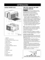
CARACTERiSTICAS
15 4 6 5 73 214
17 9 16 8 11 12 10 13
Figura 22
1. Gabinete
2. Deflector vertical de aire
3. La Direcci6n Aerea horizontal Louvers
4. Grille anterior
5. Rejilla de entrada
6. Filtro del aire
7. Tablero de control
8. Cordon de alimentaci6n electrica
9. Evaporador
10. Condensador
11. Compresor
12. Recipiente de base
13. Puntal
14. Guia superior
15. Cortina
16. Descargar el Control
17. Calentador electrico
USO DEL EQUIPO DE AIRE
ACONDICIONADO
_Para reducir el riesgo de incendio,
descargas electrica o lesiones personales, lea las
IMPORTANTES INSTRUCCIONES DE
SEGURIDAD antes de operar este aparato.
Para comenzar a utilizar el equipo de aire
acondicionado, siga estos pasos:
1. Enchufe el equipo de aire acondicionado. (Para
prevenir riesgos de descargas electricas, no use un
cable de extensi6n ni un enchufe adaptador.)
2. Ajuste el extractor de aire en la posici6n CERRADA
3. Ajuste el control de MODE al mas alto nivel fresco.
4. Ajuste el control del ventilador al m&s alto nivel.
5. Ajuste las rejillas desviadoras para Iograr un flujo
confortable de aire con la lengQeta de control.
6. Una vez que la habitaci6n se haya enfriado, ajuste
el control de temperatura TEMP a la graduaci6n
que usted considere m&s confortable.
NOTA: Si se apaga el aire acondicionado, espere 3
minutos antes de volver a encendedo. Esto permite
que se estabilice la presi6n dentro del compresor. Si
no sigue estas instrucciones, el equipo podria
funcionar con poca eficiencia.
Si usted mueve el TEMP el control a un warmer,
entonces inmediatamente espalda a una colocacion
m&s fresca, la unidad apagar&. Espere 3 minutos.
CONTROL DE VENTILAClON
El control de ventilaci6n permite que el equipo de aire
acondicionado haga recircular el aire en el interior de
la habitaci6n (CLOSE) o saque el aire hacia el exterior
(OPEN). (Figura 23)
• La posici6n CLOSE sirve cuando se desea un
enfriamiento m&ximo. Tambien puede usarse para
hacer recircular el aire sin enfriar la habitaci6n
cuando el equipo de aire acondicionado se ajusta en
la posici6n FAN.
• La posici6n OPEN extrae el aire estancado de la
habitaci6n y Io expulsa hacia fuera. El aire fresco es
Ilevado hacia el interior de la habitaci6n a traves de
los pasajes normales de aire que se hallan en los
hogares.
• La posicion OPEN o CLOSE puede usarse con
cualquier selecci6n de ventilador.
Figura 23
PULL OPEN / PUSH CLOSE
(TIRAR PARA ABRIR / EMPUJAR PARA CERRAR)
- 22 -

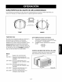
CARACTERiSTICAS DEL EQUIPODEAIRE ACONDICIONADO
Los controles que se explican en este manual son representativos de muchos modelos disponibles a la
venta en el mercado. Su modelo puede tener un aspecto ligeramente diferente.
D OFF
OFF ON FAN FAN
ONLY ONLY
Auto Swing
T[_rnoffAutoSwing
WhenOperationSwitchisoff
COOL
HIGH HIGH
HEAT COOL
TEMP
MODE
TEMPERATURA
El control de la temperatura est& para mantener la
temperatura de la habitaci6n. El compresor
circulara y dejara de circular para mantener la
habitacion en el mismo nivel de comodidad. Gire la
manija al sentido de la manecilla del reloj hacia
COOLER [Enfriador] (azul) y el aire del interior se
volver& fresco. Gire la manija al sentido contrario de
la manecilla del reloj hacia WARMER [Calefactor]
(rojo) y el aire del interior se volver& calido.
MODO
OFF
FAN ONLY :
LOW COOL :
HIGH COOL:
LOW HEAT :
HIGH HEAT:
: Apaga el aire acondicionado.
Permite el funcionamiento del
ventilador a baja velocidad sin enfriar
(calentar).
Permite el enfriamiento con el
funcionamiento del ventilador a baja
velocidad.
Permite el enfriamiento con el
funcionamiento del ventilador a alta
velocidad.
Permite el calentamiento con el
ventilador a baja velocidad.
Permite el calentamiento con el
ventilador a alta velocidad.
AUTO 8WING (OscilacionAutomatica)
On : (Encendido) La oscilacion de aire es operada
mientras la perilla Operation (operacion) se coloca
en la posicion Cool (enfriamiento).
Off : (Apagado) Detiene la operacion de Ia oscilacion
de aire.
Off _ On
Auto Swing
CONTROL DE DIRECCION VERTICAL DEL AIRE
La direcci6n vertical del aire se ajusta moviendo la
rejilla horizontal hacia delante o hacia atr&s.
Figura 24
-23-

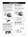
LIMPIEZA DEL FILTRO DEL AIRE
El filtro del aire se ira ensuciando a medida que va
atrapando el polvo proveniente del aire interior. Es
preciso lavar el filtro deI aire al menos cada dos
semanas. Si el filtro del aire permanece Ileno de polvo, el
flujo de aire disminuira y se reducira la capacidad de
enfriamiento del equipo, con posibles dafios para la
unidad. (Figura 25)
• Tire de Ia rejilla de entrada hacia delante agarrando
ambas lengQetas y tire del filtro del aire hasta sacarlo.
• Lave el filtro deI aire en agua tibia a. Asegurese de
eliminar toda el agua sacudiendo el filtro antes de volver
a ponerlo en su posici6n. (Figura 26)
Figura 25
Figura 26
LIMPIEZA DEL EQUIPO DE
AIRE ACONDICIONADO
La rejilla frontal y ia rejiIla de entrada del aire pueden
lavarse con un patio humedecido en una sotucion de
detergente suave. El gabinete puede lavarse con un
jabon o detergente suave y agua tibia, seguidamente
puede pulirse con cera Iiquida especial para
electrodomesticos.
Para asegurar una eficiencia maxima continua, los
serpentines dei condensador (lado de enfrente de la
unidad) deben revisarse periodicamente y iimpiarse si
estan obstruidos con hollin o con sucio de ia atmosfera.
Figura 27
COMO A REEMPLAZA EL
GRILLE ANTERIOR
• Saque el tomillo que mantiene la rejilla frontal en
posicion.
• Quite el tomillo que asegura le reja delantera.
• Empuje la rejilla hacia arriba de abajo yjale la parte de
arriba de Ia rejilla lejos de la base para levantar las
lenguetas de arriba hacia afuera de las ranuras.
Rejilla de entrada
, _ Rejilla de anterior
-= _ Figura 28
COMO A REEMPLAZA EL
GRILLE ANTERIOR
Pegue el panel frontal a la caja insertando los
fijadores en el panel adentro las aberturas de la
caja.
- 24 -

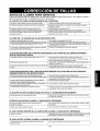
ANTES DE LLAMAR PARA SERVICIO
Cheque la siguiente lista para asegurarse si en realidad es necesario Ilamar para servicio. Una referencia rapida a
este manual puede evitar una Ilamada para servicio innecesaria.
EL EQUIPO DE AIRE ACONDICIONADO NO FUNCIONA.
Elenchufenoestaconectadoenlatomadecorrientedepared. Conecteelenchufeflrmementeenlatomadecomentedepared
Elfusibleestaquemadooel interruptordecircuitosehadisparado. ReemplaceelfusibledaSadoconunfusibledeacoidnretardadaoreajusteel
interrupterdecircuito.
ElselectordelventitadorMODEestaenla posiol6ndeOFF. PongaelselectorenlaposicidndeCOOL.
Launidadseapag6yse volvi6aencenderdemasiador@ido. Apaguela uoldady espere3minutosantesdevolveraencenderla.
ElcontroldetemperaturaTEMPseajust6m_scalidoquela Gireelcontroldetemperaturaenelsentidodelasagujasdetrelojhastauna
temperaturaambiente, graduaci6nmasfda(numeromasalto).
EL AIRE DE LA UNIDAD NO SALE BASTANTE FRiO.
Elselectora unaposici6nmasLOWCOOL
ElcontroldetemperaturaTEMPseajust6demasiadocalido(numeromasbajo).
Latemperaturaambienteest_pordebajodelos70°F (21°C)
Eltubesensordetemperaturaest_tocandoel serpentinevaporador
queest_situadodetrasdelfiltrodelaire.
ELAIREACONDICIONADOENFRIA,PEROLAHAEITACION8E81ENTEDEMASIADOCALIDA;8EFORMAHIELOENEL8ERPENTINDEENFRIAMIENTO
Gireelselectora unaposicidnHIGHCOOL.
Gireelsontroldetemperaturaenel sentidodeIasagujasdelreiojpara
Nopuedeproducirseel enfriamientohastaquelatemperaturaambientesuba
porencimadelos700F(21°0).
EndereceeltuboalejandotodeIserpentinevaporador.
DETP_SDELPANELDECORATIVOFRONTAL,
I EIflltrodelair_puedeestarsucio.
I Elco_'o parael enfriamiento
I nocturno.
ParadescongelareIserpentinIleveelselectora laposicidnFAN.
Seguidamente,gireelcontroldetemperaturaTEMPenelsenti@delasagujas
delretojparaIlevarlohastaunagraduacidnmascalida.
Limpieelflitro.Consultelasecoidn"Mantenimiento'_.Paradessongelar,Ileveel
selectora laposici6nFAN.
Paradescongelaretserpentin,Ileveelselectorala posioldnFAN.
Seguidamenteajusteel controldetemperaturaa unaposicidnmascatida.
ELAIREACONOIClONADOENFRiA,PEROLAHABITACION8E81ENTEOEMASIADOCALIDA;NO8EFORMAHIELOENEL8ERPENTINDE
ENFRIAMIENTODETRA8DELPANELDECORATIVOFRONTAL.,
ElfiltrodelaireestasucioconIoqueserestringeelflujodetaire. Limpieetfiltrodelaire.ConsulteIasecoi6n"Manteolmiento"
ElcontroldetemperaturaTEMPsegradu6enposici6ndemasiadocalida. Gireelcontroldetemperaturaenelsentidodelasagujasdelrelojparallevarloa
unagraduaci6nmasfda.(NOrneromasalto)
Elimineelbloqueoenfrentedelauoldad.Lapartefrontaldelaunidadestabloqueadapercortinas,persianas,
mueblesetc.querestrinflenladistribucidndelaire
Laspuertas,ventanas,rejillasdecalefaccidn,etcetera,estanabiertascon
Ioquesepermiteelescapedelairefrio.
Launidadacabadeencenderseenunahabitacidncatiente
Cierrelaspuertas,ventanas,rejillasdecalefaccidn,etcdtera.
Permitaquetranscurraunpocomasdetiempoparaeliminarel"caloralmacenado"
enIasparedes,ettecho,elpisoylosmuebtes.
EL EQUIPO DE AIRE ACONDICIONADO 8E APAGA Y 8E ENCIENDE RAPIDAMENTE.
Latemperaturaexterioresextrernadamentecaliente AjusteelMODOenlavetocidadALTAparahacerqueetairepaseperlabobina
derefrigeracidnmasr@ido.
8E ESCUCHAN RUID08 CUANDO LA UNIDAD ESTA ENFRIANDO.
Elsonidodeiventiladoralchocarcontrael aguadelsistemade Estoesnormalcuandolahumedadesalta.Cierrelaspuertas,ventanasy rejillas
eliminaci6ndehumedad, decalefaccidn.
Vibracidndelaventana;instalacidndeficiente. Lealasinstruccionesdeinstalaci6noconsutteal instalador.
EL AGUA GOTEA DENTRO DE LA HABITACION CUANDO LA UNIDAD ESTA ENFRIANDO.
Instalaci6ninadecuada, lndineligeramenteelequipodeaireacondidonadohacialaparteextenorparapen'nitirel
drenajedeagua.Leaas nstruccionesdensfaaddnoconsutea nstaador
ELAGUA GOTEA AFUERA CUANDO LA UNIDAD ESTA ENFRIANDO.
Launidadestaextrayendograndescantidadesdehumedaddeuna EstoesatgonormaldurantelosdiasexcesJvarnentehQmedos.
habitacidnhQmeda.
- 25 -

126 1

Master Protection Agreements
Congratulations on making a smart purchase.
Your new Kenmore ® product is designed and
manufactured for years of dependable operation.
But like all products, it may require preventive
maintenance or repair from time to time.
That's when having a Master Protection Agreement
can save you money and aggravation.
Purchase a Maser Protection Agreement now and
protect yourself from unexpected hassle and
expense.
The Master Protection Agreement also helps extend
the life of your new product. Here's what's included
in the Agreement:
[] Expert service by our 12,000 professional
repair specialists
[] Unlimited service and no charge for parts and
labor on all covered repairs
[] "No-lemon" guarantee - replacement of your
covered product if four or more product failures
occur within twelve months
[] Product replacement if your covered product
can't be fixed
[] Annual Preventive Maintenance Check at your
request - no extra charge
[] Fast help by phone - phone support from a
Sears technician on products requiring in-home
repair, plus convenient repair scheduling
[] Power surge protection against electrical
damage due to power fluctuations
[] Rental reimbursement if repair of your covered
product takes longer than promised
Once you purchase the Agreement, a simple phone
call is all that it takes for you to schedule service.
You can call anytime day or night, or schedule a
service appointment online.
Sears has over 12,000 professional repair
specialists, who have access to over 4.5 million
quality parts and accessories. That's the kind of
professionalism you can count on to help prolong
the life of your new purchase for years to come.
Purchase your Master Protection Agreement today!
Some limitations and exclusions apply.
For prices and additional information call
1-800-827-6655.
Sears Installation Service
For Sears professional installation of home
appliances, garage door openers, water
heaters, and other major home items, in the
U.S.A. call 1-800-4-MY-HOME _
Acuerdos de Proteccion Especializada
iEnhorabuena! Ha realizado una compra inteligente.
Su nuevo aparato Kenmore® esta diseSado y fabricado
para ofrecerle aSos de buen funcionamiento.
Sin embargo, al igual que todos los productos, puede
precisar un mantenimiento preventive o incluso alguna
reparacion de vez en cuando. En esas ocasiones, un
Master Protection Agreement puede ayudarle a ahorrar
dinero e inconvenientes.
Adquiera un Maser Protection Agreement ahora, y
prot_jase a si mismo de molesfias y gastos inesperados.
El Master Protection Agreement le ayudara tambien a
prolongar la vida de su nuevo aparato. Los siguientes
servicios estan incluidos:
[] Servicio experto por parte de cualquiera de
nuestros 12.000 tecnicos profesionales especialistas
de Sears.
[] PrestaciCn de servicios sin limitaciones y sin
cargarle las piezas o la mane de obra en todas ias
reparaciones cubiertas pot el acuerdo.
[] Garantia seria de sustituciSn de las piezas del
producto cubierto pot el acuerdo, si cuatro o mas
piezas se mostrasen defectuosas en un periodo de
doce meses.
[] SustituciCn del producto por otro nuevo, si ei
defectuoso no pudiese repararse.
[] Control de mantenimiento anual preventivo,
siempre que Io desee y sin gasto adicional alguno.
[] Asistencia telefCnica inmediata de un tecnico
especialista en productos que hart de ser reparados a
domicilio, ademas de una programaciCn adecuada de
la reparacion.
[] ProtecciCn contra subidas de tensiCn que
provoquen da_os elcctricos debidos alas
fluctuaciones en el suministro.
] Reintegro del alquiler si la reparacion deI producto
Ileva mas tiempo del promtetido
Una vez que haya adquirido el Agreement, no necesitara
masque una simple Ilamada para solicitar el servicio de
su aparato. Ademas, podra hacerlo en cualquier momento
del dia o de la noche, o solicitar una cita para prestacion
de servicios online.
Sears cuenta con mas de 12.000 tecnicos profesionales
especialistas en reparaciones, con acceso a mas de 4,5
miilones de piezas de sustitucion y accesorios de calidad.
Este sera el tipo de profesionalidad y servicio con el que
podra contar para prolongar la vida de su nuevo producto
por muchos athos, iAdquiera hoy mismo su Master
Protection Agreement/.
Se aplicar_n algunas limitaciones y
restricciones.
Si desea hacer alguna consulta sobre los
precios u otra informaciCn adicional, le rogamos
Ilame al tel_fono 1-800-827-6655.
Servicios de InstalaciCn Sears
Para solicitar servicios de instalaciCn profesionales
de Sears de electrodomesticos, mandos de apertura
de puertas de garajes, calentadores de agua y otros
aparatos en los Estados Unidos, puede Ilamar a
1-800-4-MY-HOME ®
- 27 -

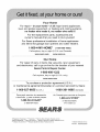
Your Home
For repair- in your home-of all major brand appliances,
lawn and garden equipment, or heating and cooling systems,
no matter who made it, no matter who sold it!
For the replacement parts, accessories and
owner's manuals that you need to do-it-yourself.
For Sears professional installation of home appliances
and items like garage door openers and water heaters.
1-800-4-MY-HOME ® (1-800-469-4663)
Call anytime, day or night (U.S.A. and Canada)
www,sears,com www.sears.ca
Our Home
For repair of carry-in items like vacuums, lawn equipment,
and electronics, call or go on-line for the location of your nearest
Sears Parts & Repair Center,
1-800-488-1222
Call anytime, day or night (U.S.A. only)
www.sears.com
To purchase a protection agreement(U.S.A.)
or maintenance agreement(Canada) on a product serviced by Sears:
1-800-827-6655 (U.S.A.) 1-800-361-6665 (Canada)
Para pedir servicio de reparaci6n Au Canada pour service en fran_ais:
a domicilio, y para ordenar piezas: 1-800-LE-FOYER M°
1-888-SU-HOGAR sM (1-800-533-6937)
(1-888-784-6427) www.sears.ca
TM SM
® Registered Trademark / Trademark / Service Mark of Sears, Roebuck and Co
TM S_,
® Marca Registrada / Marca de Fabdca / ')Marca de Servicio de Sears, Roebuck and Co.
MC MD
Marque de commerce / Marque deposee de Sears, Roebuck and Co ® Sears, Roebuckand Co.
Part No.: 3828A20292K
-
 1
1
-
 2
2
-
 3
3
-
 4
4
-
 5
5
-
 6
6
-
 7
7
-
 8
8
-
 9
9
-
 10
10
-
 11
11
-
 12
12
-
 13
13
-
 14
14
-
 15
15
-
 16
16
-
 17
17
-
 18
18
-
 19
19
-
 20
20
-
 21
21
-
 22
22
-
 23
23
-
 24
24
-
 25
25
-
 26
26
-
 27
27
-
 28
28


Kenmore 580.72187300 El manual del propietario
- Tipo
- El manual del propietario
- Este manual también es adecuado para
en otros idiomas
- English: Kenmore 580.72187300 Owner's manual
Artículos relacionados
-
Kenmore 580.75184500 El manual del propietario
-
-
-
Kenmore 580.74054400 El manual del propietario
-
-
Kenmore 580.72124300 El manual del propietario
-
-
-
Kenmore 75151 15,000 El manual del propietario
-
