La página se está cargando...

English
Español1 SAFETY INFORMATION
1.1 SAFETY WARNINGS
NOTE!
Only use the PROFIBUS DP module (CFW300-CPDP) on WEG
CFW300 series inverters.
It is recommended to read the CFW300 user manual before installing
or operating this accessory.
This guide contains important information regarding the proper
understanding and correct operation of this module.
1.2 PRELIMINARY RECOMMENDATIONS
ATTENTION!
Always disconnect the general power supply before connecting or
disconnecting the accessories of the CFW300 frequency inverter.
Wait for at least 10 minutes for the full discharge of the power
capacitors.
2 GENERAL INFORMATION
This guide provides directions for the installation, configuration and operation of
the PROFIBUS DP module (CFW300-CPDP).
3 CONTENT OF THE PACKAGE
Upon receiving the product, check if the package contains:
Accessory in anti-static package.
Installation, configuration and operation guide.
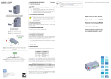
4 INSTALLATION OF THE ACCESSORY
The CFW300-CPDP is easily connected to the CFW300 frequency inverter by
means of the plug-and-play concept. The procedures below must be observed
for the proper installation and start-up:
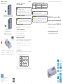
1. With the inverter de-energized, remove the inverter communication accessory
cover Figure A1.
2. Fit the accessory to be installed as shown in Figure A1.
3. Power up the inverter.
5 CONFIGURATIONS
The PROFIBUS DP interface connections must be done on the connector as
per Table 1.
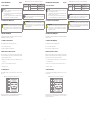
Table 1: Signals of the PROFIBUS DP communication connector
Connector
GND
RTS
B+
N.C
N.C
N.C
A-
N.C
+5 V
1 N.C
2 N.C
3 B (+)
4 RTS
5 GND
6 + 5 V
7 N.C
8 A (-)
9 N.C
The location of the DIP switch to select the PROFIBUS DP network termination can
be better viewed in Figure A2 and it must be configure as per Table 2.
Table 2: Configurations of the switches for PROFIBUS DP communication
Comunication Switch Switch Setting Option
PROFIBUS DP
S1
(*)
S1.1 = OFF and S1.2 = OFF
PROFIBUS DP termination
resistor inactive
S1.1 = ON and S1.2 = ON
PROFIBUS DP termination
resistor active
(*) No other combinations of the switches are allowed.
NOTE!
The software version of the CFW300-CPDP can be viewed in parameter
P025 of the CFW300 inverter.
ATTENTION!
For the proper operation of the CFW300 inverter with the CFW300-CPDP
module, parameters P308, P310, P311 and P312 must be set with
the factory default values. For further details refer to the CFW300
programming manual.
1 INFORMACIONES DE SEGURIDAD
1.1 AVISOS DE SEGURIDAD
¡NOTA!
Solamente utilizar el módulo PROFIBUS DP (CFW300-CPDP) en los
convertidores WEG línea CFW300.
Se recomienda la lectura del manual del usuario del CFW300 antes
de instalar o operar este accesorio.
El contenido de esta guía fornece informaciones importantes para
el correcto entendimiento y buen funcionamento de este módulo.
1.2 RECOMENDACIONES PRELIMINARES
¡ATENCIÓN!
Siempre desconecte la alimentación general antes de conectar o
desconectar los accesorios del convertidor de frecuencia CFW300.
Espere al menos 10 minutos para garantizar la desenergización
completa del convertidor.
2 INFORMACIONES GENERALES
Esta guía orienta en la instalación, configuración y operación del módulo PROFIBUS
DP (CFW300-CPDP).
3 CONTENIDO DEL EMBALAJE
Al recibir el producto, verificar si el embalaje contiene::
Accesorio en embalaje antiestático.
Guía de instalación, configuración y operación.
4 INSTALACIÓN DEL ACCESORIO
El CFW300-CPDP es fácilmente conectado al convertidor de frecuencia CFW300
utilizando el concepto “plug-and-play”. Deben ser seguidos los procedimientos de
abajo, para la correcta instalación y puesta en funcionamiento:
1. Con el convertidor sin tensión, retire la tapa de los accesorios de comunicación
del convertidor Figura A1.
2. Encaje el accesorio a ser instalado, conforme es indicado en la Figura A1.
3. Energice el convertidor.
5 CONFIGURACIONES
Las conexiones de la interfaz PROFIBUS DP deben ser hechas en el conector,
conforme la Tabla 1.
Tabla 1: Señales del conector de comunicación PROFIBUS DP
Conector
GND
RTS
B+
N.C
N.C
N.C
A-
N.C
+5 V
1 N.C
2 N.C
3 B (+)
4 RTS
5 GND
6 + 5 V
7 N.C
8 A (-)
9 N.C
La localización de las DIP-switches para selección de la terminación de la red
PROFIBUS DP pueden ser mejor visualizadas en la Figura A2 e deben ser
configurado conforme la Tabla 2.
Tabla 2: Configuraciones de las llaves para comunicación PROFIBUS DP
Comunicación Llave Ajuste de las Llaves Opción
PROFIBUS DP
S1
(*)
S1.1 = OFF y S1.2 = OFF
PROFIBUS DP resistor de
terminación inactivo
S1.1 = ON y S1.2 = ON
PROFIBUS DP resistor de
terminación activo
(*) Cualquier otra combinación de las llaves no está permitida.
¡NOTA!
La versión de software del accesorio CFW300-CPDP puede ser
visualizada en el parámetro P025 del convertidor CFW300.
¡ATENCIÓN!
Para el correcto funcionamiento del convertidor CFW300 con el módulo
CFW300-CPDP, los parámetros P308, P310, P311 y P312 deben estar
ajustados con los valores estándar de fábrica. Por más detalles, consulte
el manual de programación del CFW300.
Transcripción de documentos
1 SAFETY INFORMATION English Table 2: Configurations of the switches for PROFIBUS DP communication Comunication 1.1 SAFETY WARNINGS Switch Switch Setting S1.1 = OFF and S1.2 = OFF PROFIBUS DP S1 (*) S1.1 = ON and S1.2 = ON NOTE! Only use the PROFIBUS DP module (CFW300-CPDP) on WEG CFW300 series inverters. Option PROFIBUS DP termination resistor inactive PROFIBUS DP termination resistor active (*) No other combinations of the switches are allowed. It is recommended to read the CFW300 user manual before installing or operating this accessory. This guide contains important information regarding the proper understanding and correct operation of this module. 1.2 PRELIMINARY RECOMMENDATIONS Always disconnect the general power supply before connecting or disconnecting the accessories of the CFW300 frequency inverter. Wait for at least 10 minutes for the full discharge of the power capacitors. Español 1.1 AVISOS DE SEGURIDAD PROFIBUS DP convertidores WEG línea CFW300. NOTE! The software version of the CFW300-CPDP can be viewed in parameter P025 of the CFW300 inverter. For the proper operation of the CFW300 inverter with the CFW300-CPDP module, parameters P308, P310, P311 and P312 must be set with the factory default values. For further details refer to the CFW300 programming manual. de instalar o operar este accesorio. El contenido de esta guía fornece informaciones importantes para el correcto entendimiento y buen funcionamento de este módulo. 1.2 RECOMENDACIONES PRELIMINARES ¡ATENCIÓN! Siempre desconecte la alimentación general antes de conectar o desconectar los accesorios del convertidor de frecuencia CFW300. Espere al menos 10 minutos para garantizar la desenergización 4 INSTALLATION OF THE ACCESSORY 4 INSTALACIÓN DEL ACCESORIO The CFW300-CPDP is easily connected to the CFW300 frequency inverter by means of the plug-and-play concept. The procedures below must be observed for the proper installation and start-up: El CFW300-CPDP es fácilmente conectado al convertidor de frecuencia CFW300 utilizando el concepto “plug-and-play”. Deben ser seguidos los procedimientos de abajo, para la correcta instalación y puesta en funcionamiento: 1. With the inverter de-energized, remove the inverter communication accessory cover Figure A1. 1. Con el convertidor sin tensión, retire la tapa de los accesorios de comunicación del convertidor Figura A1. 2. Fit the accessory to be installed as shown in Figure A1. 2. Encaje el accesorio a ser instalado, conforme es indicado en la Figura A1. 3. Power up the inverter. 3. Energice el convertidor. 5 CONFIGURATIONS 5 CONFIGURACIONES The PROFIBUS DP interface connections must be done on the connector as per Table 1. Las conexiones de la interfaz PROFIBUS DP deben ser hechas en el conector, conforme la Tabla 1. Table 1: Signals of the PROFIBUS DP communication connector Tabla 1: Señales del conector de comunicación PROFIBUS DP +5 V N.C A- RTS N.C +5 V N.C RTS Conector 1 N.C 2 N.C 3 B (+) 4 RTS 5 GND 6 +5V 7 N.C 8 A (-) 9 N.C N.C Guía de instalación, configuración y operación. B+ Accesorio en embalaje antiestático. Installation, configuration and operation guide. N.C Al recibir el producto, verificar si el embalaje contiene:: Accessory in anti-static package. GND Upon receiving the product, check if the package contains: N.C 3 CONTENIDO DEL EMBALAJE B+ 3 CONTENT OF THE PACKAGE N.C Esta guía orienta en la instalación, configuración y operación del módulo PROFIBUS DP (CFW300-CPDP). A- Opción PROFIBUS DP resistor de terminación inactivo PROFIBUS DP resistor de terminación activo (*) Cualquier otra combinación de las llaves no está permitida. ¡NOTA! La versión de software del accesorio CFW300-CPDP puede ser visualizada en el parámetro P025 del convertidor CFW300. ¡ATENCIÓN! 2 INFORMACIONES GENERALES GND (*) S1.1 = ON y S1.2 = ON Solamente utilizar el módulo PROFIBUS DP (CFW300-CPDP) en los This guide provides directions for the installation, configuration and operation of the PROFIBUS DP module (CFW300-CPDP). N.C S1 ¡NOTA! completa del convertidor. The location of the DIP switch to select the PROFIBUS DP network termination can be better viewed in Figure A2 and it must be configure as per Table 2. Ajuste de las Llaves S1.1 = OFF y S1.2 = OFF 2 GENERAL INFORMATION Connector 1 N.C 2 N.C 3 B (+) 4 RTS 5 GND 6 +5V 7 N.C 8 A (-) 9 N.C Tabla 2: Configuraciones de las llaves para comunicación PROFIBUS DP Comunicación Llave Se recomienda la lectura del manual del usuario del CFW300 antes ATTENTION! ATTENTION! 1 INFORMACIONES DE SEGURIDAD La localización de las DIP-switches para selección de la terminación de la red PROFIBUS DP pueden ser mejor visualizadas en la Figura A2 e deben ser configurado conforme la Tabla 2. Para el correcto funcionamiento del convertidor CFW300 con el módulo CFW300-CPDP, los parámetros P308, P310, P311 y P312 deben estar ajustados con los valores estándar de fábrica. Por más detalles, consulte el manual de programación del CFW300.-
 1
1
-
 2
2


en otros idiomas
- English: WEG PROFIBUS DP User guide
- português: WEG PROFIBUS DP Guia de usuario
Artículos relacionados
-
WEG CFW300 CETH0 Instrucciones de operación
-
WEG USB Guía del usuario
-
 Automation Direct CFW300 Manual de usuario
-
 Automation Direct RS485 Guía del usuario
-
-
-
-
-
 Automation Direct Serial Remote HMI Set Guía del usuario
-


