La página se está cargando...

English
Español
1 SAFETY INFORMATION
1.1 SAFETY INFORMATION
NOTE!
Only use the CAN communication module (CFW300-CCAN) on WEG
CFW300 series inverters.
It is recommended to read the CFW300 user manual before installing
or operating this accessory.
This guide contains important information regarding the proper
understanding and correct operation of this module.
1.2 PRELIMINARY RECOMMENDATIONS
ATTENTION!
Always disconnect the general power supply before connecting or
disconnecting the accessories of the CFW300 frequency inverter.
Wait for at least 10 minutes for the full discharge of the inverter.
2 GENERAL INFORMATION
This guide provides directions for the installation, configuration and operation of
the CAN communication module (CFW300-CCAN).
3 PACKAGE CONTENT
Upon receiving the product, check if the package contains:
Accessory in anti-static package.
Installation, configuration and operation guide.
4 INSTALLATION OF THE ACCESSORY
The CFW300-CCAN is easily connected to the CFW300 frequency inverter by
means of the plug-and-play concept. The procedures below must be observed
for the proper installation and start-up:
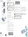
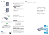
1. With the inverter de-energized, remove the inverter communication accessory
cover (Figure A1).
2. Fit the accessory to be installed as shown in Figure A1.
3. Power up the inverter.
5 CONFIGURATIONS
The CFW300-CCAN communication module has a 5-way connector with the
following characteristics:
It enables the CANopen and DeviceNet communication of the product.
It has communication network interface with galvanic isolation and differential
signal, providing more robustness against electromagnetic interference.
It allows the connection of up to 64 devices to the same segment. A great
number of devices can be connected by using repeaters. The limit of devices
that can be connected to the network depends on the used protocol.
Maximum bus length of 1000 meters.
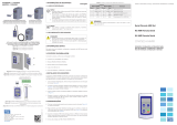
It requires an external power supply between pins 25 and 29 (Figure A2) of
the network connector. The data for individual consumption and input voltage
are shown in Table 2.
The alarm, fault and status indications of the communication are made
trough the HMI and parameters of the product. For further details refer to the
programming manual of the CFW300 and CANopen user´s manual.
Table 1: Pin assignment of the connector for CAN interface
Connector Description
25 V (-) Negative pole of the power supply
26 CAN_L Communication signal CAN_L
27 Shield Cable shield
28 CAN_H Communication signal CAN_H
29 V (+) Positive pole of the power supply
Table 2: Pin assignment of the connector for CAN interface
Power Supply (VDC)
Minimum Maximum Recommended
11 30 24
Current (mA)
Typical Maximum
30 50
In order to connect the CFW300 frequency inverter using this module, the following
items must be observed:
It is recommended the use of specific cables for CANopen and DeviceNet
network.
The grounding of the cable shield must be done in one point only, thus avoiding
long current loops. This point is normally the network power supply. If more
than one power supply is present, only one of them must be connected to
the protective earth.
Installation of the termination resistors only at the ends of the main bus, even
if there are derivations.
The power supply of the network must be able to supply current enough to
feed all the transceivers of the equipments. The CFW300-CCAN module
consumes about 50 mA.
For further details about the installation of the CANopen and DeviceNet
communication network, refer to the user manual of the CANopen and DeviceNet,
respectively.
NOTE!
The software version of the CFW300-CCAN can be viewed in parameter
P025 of the CFW300 inverter.
ATTENTION!
For the proper operation of the CFW300 inverter with the CFW300-CCAN
module, parameters P308, P310, P311 and P312 must be programmed
with the factory settings. For further details, refer to the programming
manual of the CFW300.
1 INFORMACIONES DE SEGURIDAD
1.1 AVISOS DE SEGURIDAD
¡NOTA!
Solamente utilizar el módulo de comunicación (CFW300-CCAN) en
los convertidores WEG serie CFW300.
Se recomienda la lectura del manual del usuario del CFW300 antes
de instalar o operar ese accesorio.
El contenido de esta guía provee informaciones para el correcto
entendimiento y el buen funcionamiento de este módulo.
1.2 RECOMENDACIONES PRELIMINARES
¡ATENCIÓN!
Siempre desconecte la alimentación general antes de conectar o
desconectar los accesorios del convertidor de frecuencia CFW300.
Aguarde por el menos 10 minutos para garantizar la desenergización
completa del convertidor.
2 INFORMACIONES GENERALES
Esta guía orienta en la instalación, configuración y operación del módulo de
comunicación CAN (CFW300-CCAN).
3 CONTENIDO DEL EMBALAJE
Al recibir el producto, verificar si el embalaje contiene:
Accesorio en embalaje antiestático.
Guía de instalación, configuración y operación.
4 INSTALACIÓN DEL ACCESORIO
El CFW300-CCAN es fácilmente conectado al convertidor de frecuencia CFW300
utilizando el concepto “plug and play”. Deben ser seguidos los procedimientos de
abajo para la correcta instalación y puesta en funcionamiento:
1. Con el convertidor sin tensión, retire la tapa de los accesorios de comunicación
del convertidor (Figura A1).
2. Encaje el accesorio a ser instalado, conforme es indicado en la Figura A1.
3. Energice el convertidor.
5 CONFIGURACIONES
El módulo de comunicación CFW300-CCAN posee un conector de 5 vías para
comunicación CAN con las siguientes características:
Posibilita la comunicación CANopen y DeviceNet en el producto.
Posee Interfaz de red de comunicación aislada galvánicamente y con señal
diferencial, otorgando mayor robustez contra interferencia electromagnética.
Permite la conexión de hasta 64 dispositivos en el mismo segmento. Puede
ser conectada una cantidad mayor de dispositivos, con el uso de repetidores.
El número límite de equipos que pueden ser conectados en la red también
depende del protocolo utilizado.
Longitud máxima de 1000 metros del embarrado.
Necesita una tensión de alimentación externa entre los pernos 25 y 29 (Figura
A2) del conector de la red. Los datos para consumo individual y tensión de
entrada son presentados en la Tabla 2.
Las indicaciones de alarmas, fallas y estados de la comunicación son hechas a
través de la HMI y de los parámetros del producto. Por más detalles, consulte
el manual de programación del CFW300 y manual de comunicación CANopen.
Tabla 1: Sujeción del conector para Interfaz CAN
Conector Descripción
25 V (-) Polo negativo de la fuente de alimentación
26 CAN_L Señal de comunicación CAN_L
27 Shield Blindaje del cable
28 CAN_H Señal de comunicación CAN_H
29 V (+) Polo positivo de la fuente de alimentación
Tabla 2: Sujeción del conector para interfaz CAN
Tensión de Alimentación (VCC)
Mínimo Máximo Recomendado
11 30 24
Corriente (mA)
Típico Máximo
30 50
Para la conexión del convertidor de frecuencia CFW300, utilizando este módulo,
deben ser observados los siguientes puntos:
Se recomienda la utilización de cables específicos para red CANopen y
DeviceNet.
Puesta a tierra de la malla del cable (blindaje) solamente en un punto, evitando
loops de corriente. Este punto suele ser la propia fuente de alimentación de
la red. Si existe más de una fuente de alimentación, solamente una de ellas
deberá estar conectada a tierra de protección.
Instalación de resistores de terminación: solamente en los extremos del
embarrado principal, aunque existan derivaciones.
La fuente de alimentación de la red debe ser capaz de suministrar corriente
para alimentar todos los transceivers de los equipos. El módulo CFW300-CCAN
consume aproximadamente 50 mA.
Para más detalles sobre la instalación de la red y la comunicación CANopen
y DeviceNet, consulte el manual del usuario del CANopen y DeviceNet,
respectivamente.
¡NOTA!
La versión de software del accesorio CFW300-CCAN puede ser
visualizada en el parámetro P025 del convertidor CFW300.
¡ATENCIÓN!
Para el correcto funcionamiento del convertidor CFW300 con el módulo
CFW300-CCAN, los parámetros P308, P310, P311 y P312 deben estar
ajustados con los valores estándar de fábrica. Por más detalles, consulte
el manual de programación del CFW300.
Transcripción de documentos
1 SAFETY INFORMATION English Table 2: Pin assignment of the connector for CAN interface 1.1 SAFETY INFORMATION Minimum 11 NOTE! Typical 30 Only use the CAN communication module (CFW300-CCAN) on WEG CFW300 series inverters. It is recommended to read the CFW300 user manual before installing or operating this accessory. This guide contains important information regarding the proper understanding and correct operation of this module. 1.2 PRELIMINARY RECOMMENDATIONS Power Supply (VDC) Maximum Recommended 30 24 Current (mA) Maximum 50 In order to connect the CFW300 frequency inverter using this module, the following items must be observed: It is recommended the use of specific cables for CANopen and DeviceNet network. 1 INFORMACIONES DE SEGURIDAD Español Always disconnect the general power supply before connecting or disconnecting the accessories of the CFW300 frequency inverter. Wait for at least 10 minutes for the full discharge of the inverter. long current loops. This point is normally the network power supply. If more than one power supply is present, only one of them must be connected to the protective earth. Installation of the termination resistors only at the ends of the main bus, even if there are derivations. 2 GENERAL INFORMATION This guide provides directions for the installation, configuration and operation of the CAN communication module (CFW300-CCAN). 3 PACKAGE CONTENT Upon receiving the product, check if the package contains: Accessory in anti-static package. Installation, configuration and operation guide. The power supply of the network must be able to supply current enough to feed all the transceivers of the equipments. The CFW300-CCAN module consumes about 50 mA. For further details about the installation of the CANopen and DeviceNet communication network, refer to the user manual of the CANopen and DeviceNet, respectively. NOTE! The software version of the CFW300-CCAN can be viewed in parameter P025 of the CFW300 inverter. 4 INSTALLATION OF THE ACCESSORY The CFW300-CCAN is easily connected to the CFW300 frequency inverter by means of the plug-and-play concept. The procedures below must be observed for the proper installation and start-up: 1. With the inverter de-energized, remove the inverter communication accessory cover (Figure A1). 2. Fit the accessory to be installed as shown in Figure A1. 3. Power up the inverter. ATTENTION! For the proper operation of the CFW300 inverter with the CFW300-CCAN module, parameters P308, P310, P311 and P312 must be programmed with the factory settings. For further details, refer to the programming manual of the CFW300. ¡NOTA! Solamente utilizar el módulo de comunicación (CFW300-CCAN) en los convertidores WEG serie CFW300. Se recomienda la lectura del manual del usuario del CFW300 antes de instalar o operar ese accesorio. El contenido de esta guía provee informaciones para el correcto entendimiento y el buen funcionamiento de este módulo. 1.2 RECOMENDACIONES PRELIMINARES ¡ATENCIÓN! Siempre desconecte la alimentación general antes de conectar o desconectar los accesorios del convertidor de frecuencia CFW300. Aguarde por el menos 10 minutos para garantizar la desenergización completa del convertidor. 2 INFORMACIONES GENERALES Esta guía orienta en la instalación, configuración y operación del módulo de comunicación CAN (CFW300-CCAN). 3 CONTENIDO DEL EMBALAJE Al recibir el producto, verificar si el embalaje contiene: Accesorio en embalaje antiestático. Guía de instalación, configuración y operación. 4 INSTALACIÓN DEL ACCESORIO El CFW300-CCAN es fácilmente conectado al convertidor de frecuencia CFW300 utilizando el concepto “plug and play”. Deben ser seguidos los procedimientos de abajo para la correcta instalación y puesta en funcionamiento: 1. Con el convertidor sin tensión, retire la tapa de los accesorios de comunicación del convertidor (Figura A1). 2. Encaje el accesorio a ser instalado, conforme es indicado en la Figura A1. 5 CONFIGURACIONES The CFW300-CCAN communication module has a 5-way connector with the following characteristics: It enables the CANopen and DeviceNet communication of the product. It has communication network interface with galvanic isolation and differential signal, providing more robustness against electromagnetic interference. It allows the connection of up to 64 devices to the same segment. A great number of devices can be connected by using repeaters. The limit of devices that can be connected to the network depends on the used protocol. Maximum bus length of 1000 meters. It requires an external power supply between pins 25 and 29 (Figure A2) of the network connector. The data for individual consumption and input voltage are shown in Table 2. El módulo de comunicación CFW300-CCAN posee un conector de 5 vías para comunicación CAN con las siguientes características: Posibilita la comunicación CANopen y DeviceNet en el producto. Posee Interfaz de red de comunicación aislada galvánicamente y con señal diferencial, otorgando mayor robustez contra interferencia electromagnética. Permite la conexión de hasta 64 dispositivos en el mismo segmento. Puede ser conectada una cantidad mayor de dispositivos, con el uso de repetidores. El número límite de equipos que pueden ser conectados en la red también depende del protocolo utilizado. Longitud máxima de 1000 metros del embarrado. Necesita una tensión de alimentación externa entre los pernos 25 y 29 (Figura The alarm, fault and status indications of the communication are made A2) del conector de la red. Los datos para consumo individual y tensión de entrada son presentados en la Tabla 2. trough the HMI and parameters of the product. For further details refer to the programming manual of the CFW300 and CANopen user´s manual. Las indicaciones de alarmas, fallas y estados de la comunicación son hechas a Table 1: Pin assignment of the connector for CAN interface 25 26 27 28 29 Connector V (-) CAN_L Shield CAN_H V (+) Description Negative pole of the power supply Communication signal CAN_L Cable shield Communication signal CAN_H Positive pole of the power supply Para la conexión del convertidor de frecuencia CFW300, utilizando este módulo, deben ser observados los siguientes puntos: Se recomienda la utilización de cables específicos para red CANopen y DeviceNet. Puesta a tierra de la malla del cable (blindaje) solamente en un punto, evitando 3. Energice el convertidor. 5 CONFIGURATIONS Tensión de Alimentación (VCC) Mínimo Máximo Recomendado 11 30 24 Corriente (mA) Típico Máximo 30 50 1.1 AVISOS DE SEGURIDAD The grounding of the cable shield must be done in one point only, thus avoiding ATTENTION! Tabla 2: Sujeción del conector para interfaz CAN través de la HMI y de los parámetros del producto. Por más detalles, consulte el manual de programación del CFW300 y manual de comunicación CANopen. Tabla 1: Sujeción del conector para Interfaz CAN Conector 25 V (-) 26 CAN_L 27 Shield 28 CAN_H 29 V (+) Descripción Polo negativo de la fuente de alimentación Señal de comunicación CAN_L Blindaje del cable Señal de comunicación CAN_H Polo positivo de la fuente de alimentación loops de corriente. Este punto suele ser la propia fuente de alimentación de la red. Si existe más de una fuente de alimentación, solamente una de ellas deberá estar conectada a tierra de protección. Instalación de resistores de terminación: solamente en los extremos del embarrado principal, aunque existan derivaciones. La fuente de alimentación de la red debe ser capaz de suministrar corriente para alimentar todos los transceivers de los equipos. El módulo CFW300-CCAN consume aproximadamente 50 mA. Para más detalles sobre la instalación de la red y la comunicación CANopen y DeviceNet, consulte el manual del usuario del CANopen y DeviceNet, respectivamente. ¡NOTA! La versión de software del accesorio CFW300-CCAN puede ser visualizada en el parámetro P025 del convertidor CFW300. ¡ATENCIÓN! Para el correcto funcionamiento del convertidor CFW300 con el módulo CFW300-CCAN, los parámetros P308, P310, P311 y P312 deben estar ajustados con los valores estándar de fábrica. Por más detalles, consulte el manual de programación del CFW300.-
 1
1
-
 2
2


en otros idiomas
- English: WEG CAN User guide
- português: WEG CAN Guia de usuario
Artículos relacionados
-
WEG CFW300 Guía de inicio rápido
-
WEG CFW300 CETH0 Instrucciones de operación
-
-
WEG CFW100 Guía del usuario
-
WEG SSW-06 Guía de instalación
-
 Automation Direct Serial Remote HMI Set Guía del usuario
-
-
-
 Automation Direct CFW300 Manual de usuario
-
 Automation Direct RS485 Guía del usuario


