
A
Hardware Review
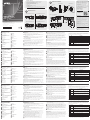
KE8950T/KE8952T Front View
1
KVM Ports
2
RS-232 Serial Port
3
Remote / Local LED
KE8950T/KE8952T Rear View
1
Grounding Terminal
2
Power Jack
3
Function Switch
4
Reset
5
RS-232 Port
KE8950R/KE8952R Front View
1
Power LED
2
LAN LED
3
Local LED
4
Remote LED
KE8950R/KE8952R Rear View
1
Grounding Terminal
2
Power Jack
3
Function Switch
4
Reset
5
RS-232 Port
6
Audio Ports
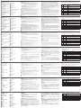
B
Hardware Installation
Rack Mounting
1. Use the screws provided with the mounting kit to screw the mounting bracket to
the bottom of the unit (Refer to the drawings shown above).
2. Screw the mounting bracket to any convenient location on the rack.
Note: Rack screws are not provided to mount the unit. We recommend that you use
M5 x 12 Phillips type I cross screws.
Wall Mounting
1. Use the screws provided with the mounting kit to screw the mounting bracket to
the bottom of the unit (Refer to the drawings shown above).
2. Use the mounting bracket’s center screw hole to mount the unit on a wall.
Point-to-Point Installation
1
(Optional) Use the grounding wire to connect the extender’s grounding terminal to
a suitable grounded object.
2
On the transmitter side, plug the mouse, keyboard, HDMI monitor, microphone
and speakers into the ports on the Console section of the KE8950T / KE8952T.
Each port is marked with an appropriate icon to indicate its function.
3
Connect the USB HDMI KVM cable provided with this package into the KVM Ports
and the audio ports on the front of the KE8950T / KE8952T.
4
Connect the other end of the USB HDMI KVM cable into the keyboard, video,
mouse, speaker and microphone ports on the computer.
5
For control of serial devices, connect the RS-232 serial port on the transmitter to a
serial port on the computer.
6
Connect a Cat 5e/6 cable to the KE8950T / KE8952T’s LAN port.
7
Plug the power adapter into an AC source with the power cord; then plug the
other end into the KE8950T’s power jack. (The KE8952 supports Power over
Ethernet (PoE), thus the power can be supplied through PoE Network Switch,
without the need of a power adapter.)
8
On the receiver side, plug the mouse, keyboard, HDMI monitor, microphone, and
speakers into the ports on the Console section of the KE8950R / KE8952R.
9
Connect the other end of the Cat 5e/6 cable to the KE8950R / KE8952R's LAN
port.
10
Instead of connecting through the LAN ports, you can choose to connect the
KE8950 through the SFP ports. To do so, plug SFP modules into the KE8950T /
KE8950R’s SFP ports, then connect each end of Gigabit Ethernet (GbE) optical fi ber
cable to the respective SFP modules on KE8950T and KE8950R.*
11
Plug the second power adapter into an AC source with the power cord; then plug
the other end into the KE8950R’s power jack.
12
Power on the computer.
*The SFP module is sold separately. Contact your ATEN dealer for product information.
OSD Options
The On-Screen Display is a keyboard and mouse driven menu-based application to
handle control and confi guration of KE operations locally. Both the transmitter and
receiver units are confi gured from the OSD menu on the receiver. Once the transmitter
and receiver units have discovered each other (over a network or direct connection)
you can use the receiver's OSD menu to maintain confi guration and control of the
setup. To setup a network based installation, download the KE user manual from our
website for detailed instructions: www.aten.com
To invoke the OSD, either press the front panel OSD pushbutton (receiver only), or tap
the [Scroll Lock] key twice. Password information is provided under OSD Options.
To exit the OSD, press the [Esc] key; click Logout or Back to Video from the OSD menu;
or return to the OSD Main menu and press the front panel OSD pushbutton. When
the OSD menu exits, the computer’s screen will appear.
No. Item Description
1 User Station
Select this radio button, enter the password, and click Confi gure
to enter the User Station confi guration screen.
2 Transmitter
Select this radio button, enter the password, and click Confi gure
to enter the Transmitter confi guration screen.
3
User
Preferences
Select this radio button, enter the password, and click Confi gure
to enter the User Preferences confi guration screen.
4 About About provides information about the current version of the OSD.
5 Password
Enter the password and click Confi gure to enter the selected
confi guration screen.
6 Confi gure
After entering a password, click this button to enter the selected
confi guration screen.
7
Back to
Video
Click this button to exit the OSD and return to the computer’s
video display.
Note: The password to enter the OSD confi guration screens is:
password
. The
username / password to enter the System Login page in Matrix Mode is:
administrator / password
.
KE8950 / KE8952 HDMI KVM over IP Extender
www.aten.com
Extension HDMI KVM sur IP KE8950 / KE8952
www.aten.com
HDMI-KVM-over-IP-Extender KE8950 / KE8952
www.aten.com
Extensor KVM HDMI sobre IP KE8950 / KE8952
www.aten.com
KE8950 / KE8952 Extender HDMI KVM su IP
www.aten.com
4
LAN LED
5
Power LED
6
Audio Ports
6
Audio Ports
7
USB Ports (Console)
8
LAN Port
9
SFP Port
10
HDMI Output (Console)
5
Graphics Pushbutton
6
OSD Pushbutton
7
Video Pushbutton
8
USB Port
7
USB Port (Peripheral)
8
USB Ports (Console)
9
LAN Port
10
SFP Port
11
HDMI Output
A
Présentation du matériel
Vue de face du KE8950T/KE8952T
1
Ports KVM
2
Port série RS-232
3
Voyant LED Distant / Local
Vue de dos du KE8950T/KE8952T
1
Borne de terre
2
Fiche d'alimentation
3
Commutateur de fonction
4
Réinitialiser
5
Port RS-232
Vue de face du KE8950R/KE8952R
1
LED d'alimentation
2
LED LAN
3
LED Local
4
LED Distant
Vue de dos du KE8950R/KE8952R
1
Borne de terre
2
Fiche d'alimentation
3
Commutateur de fonction
4
Réinitialiser
5
Port RS-232
6
Ports audio
B
Installation du matériel
Montage en rack
1. Utilisez les vis fournies dans le Kit de montage pour visser le support de montage en
partie inférieure de l’appareil (reportez-vous aux plans ci-dessus).
2. Vissez le support de montage sur un quelconque emplacement pratique sur le rack.
Remarque : Les vis de rack ne sont pas fournies pour le montage de l’appareil. Nous
vous conseillons d'utiliser des vis cruciformes M5 x 12 Phillips type I.
Montage au mur
1. Utilisez les vis fournies dans le Kit de montage pour visser le support de montage en
partie inférieure de l’appareil (reportez-vous aux plans ci-dessus).
2. Utilisez le trou de vis central du support de montage pour monter l’appareil sur un
mur.
Installation point-à-point
1
(Optionnel) Utilisez le fi l de mise à la terre pour raccorder la borne de mise à la
terre de l’extension à un objet relié à une terre appropriée.
2
Sur le côté Émetteur, branchez la souris, le clavier, le moniteur HDMI, les
microphones et les haut-parleurs dans les ports de la section console du KE8950T /
KE8952T. Chaque port est marqué avec une icône appropriée pour indiquer sa
fonction.
3
Connectez le câble KVM HDMI USB fourni avec l’emballage sur les ports KVM et
les ports audio à l’avant du KE8950T / KE8952T.
4
Raccordez l’autre extrémité du câble KVM HDMI USB sur les ports clavier, vidéo,
haut-parleurs et microphone de l’ordinateur.
5
Pour contrôler des appareils en série, connectez le port série RS-232 du récepteur à
un port série de l'ordinateur.
6
Connectez un câble Cat 5e/6 au port LAN du KE8950T / KE8952T.
7
Branchez l’adaptateur secteur sur une source CA avec le cordon d’alimentation,
puis branchez l'autre extrémité dans la prise d'alimentation du KE8950T. (Le
KE8952 prend en charge le POE (Power over Ethernet), donc l’alimentation peut
être fournie via le commutateur réseau PoE, sans besoin d’adaptateur secteur.)
8
Sur le côté Récepteur, branchez la souris, le clavier, le moniteur HDMI, le
microphone et les haut-parleurs dans les ports de la section console du KE8950R /
KE8952R.
9
Connectez l'autre extrémité du câble Cat 5e/6 au port LAN du KE8950R / KE8952R.
10
Au lieu de le connecter via les ports LAN, vous pouvez choisir de connecter le
KE8950 via les ports SFP. Pour ce faire, branchez les modules SFP sur les ports SFP
du KE8950T / KE8950R, puis raccordez chaque extrémité du câble à fi bre optique
Gigabit Ethernet (GbE) aux modules SFP respectifs sur le KE8950T et le KE8950R.*
11
Branchez le second adaptateur secteur sur une source CA avec le cordon
d’alimentation, puis branchez l'autre extrémité dans la prise d'alimentation du
KE8950R.
12
Allumez les ordinateurs.
* Le module SFP est vendu séparément. Contactez votre revendeur ATEN pour des
informations sur le produit.
Options de l’OSD
Le menu sur écran est une application à menus pilotée par le clavier et la souris, afi n
de contrôler et confi gurer localement le fonctionnement du KE. Les unités émetteur
et récepteur sont toutes deux confi gurées depuis le menu OSD sur le récepteur.
Une fois que les unité émetteur et récepteur se sont découvertes l’une l’autre (via
une connexion réseau ou directe), vous pouvez utiliser le menu OSD du récepteur
pour maintenir la confi guration et contrôler l’installation. Pour mettre en place une
installation basée sur le réseau, téléchargez le manuel d'utilisation du KE depuis notre
site Web pour des instructions détaillées : www.aten.com
Pour appeler l’OSD, appuyez sur le bouton poussoir de l’OSD en face avant (récepteur
uniquement), ou appuyez deux fois sur la touche [Arrêt défi l]. Les informations de mot
de passe sont fournies sous les options de l’OSD.
Pour quitter l’OSD, appuyez sur la touche [Échap]; cliquez sur Déconnexion ou Retour
à la vidéo depuis le menu OSD; ou retournez au menu principal de l’OSD et appuyez
sur le bouton poussoir de l’OSD en face avant. Lorsque le menu OSD se ferme, l’écran
de l’ordinateur apparait.
N° élément Description
1
Station
utilisateur
Sélectionnez ce bouton radio, entrez le mot de passe, et cliquez sur
Confi gurer pour entrer dans l’écran de confi guration de la Station
utilisateur.
2 Émetteur
Sélectionnez ce bouton radio, entrez le mot de passe, et cliquez sur
Confi gurer pour entrer dans l’écran de confi guration de l’Émetteur.
3
Préférences
utilisateur
Sélectionnez ce bouton radio, entrez le mot de passe, et cliquez sur
Confi gurer pour entrer dans l’écran de confi guration des Préférences
utilisateur.
4 À propos
À propos fournit des informations à propos de la version actuelle de
l’OSD.
5
Mot de
passe
Entrez le mot de passe, et cliquez sur Confi gurer pour entrer dans
l’écran de confi guration sélectionné.
6 Confi gurer
Après avoir entré un mot de passe, cliquez sur ce bouton pour entrer
dans l’écran de confi guration sélectionné.
7
Retour à la
vidéo
Cliquez sur ce bouton pour quitter l’OSD et retourner à l’affi chage
vidéo de l’ordinateur.
Remarque : Le mot de passe pour entrer dans les écrans de confi guration de l’OSD est :
password (mot de passe).
L’identifi ant / le mot de passe pour entrer dans
la page de connexion au système en mode Matrice est :
administrator /
password (administrateur / mot de passe).
4
LED LAN
5
LED d'alimentation
6
Ports audio
6
Ports audio
7
Ports USB (Console)
8
Port LAN
9
Port SFP
10
Sortie HDMI (Console)
5
Bouton poussoir Graphique
6
Bouton poussoir OSD
7
Bouton poussoir Vidéo
8
Port USB
7
Ports USB (Périphérique)
8
Ports USB (Console)
9
Port LAN
10
Port SFP
11
Sortie HDMI
A
Hardwareübersicht
KE8950T/KE8952T – Ansicht von vorne
1
KVM-Ports
2
Serieller RS-232-Anschluss
3
Extern- / Lokal-LED
KE8950T/KE8952T – Ansicht von hinten
1
Erdungsklemme
2
Netzanschluss
3
Funktionsschalter
4
Reset
5
RS-232-Anschluss
KE8950R/KE8952R – Ansicht von vorne
1
Betriebsanzeige-LED
2
LAN-LED
3
Lokal-LED
4
Extern-LED
KE8950R/KE8952R – Ansicht von hinten
1
Erdungsklemme
2
Netzanschluss
3
Funktionsschalter
4
Reset
5
RS-232-Anschluss
6
Audioanschlüsse
B
Hardwareinstallation
Rackmontage
1. Befestigen Sie die Montagehalterung mit den im Montageset enthaltenen Schrauben
an der Unterseite des Gerätes (siehe Abbildungen oben).
2. Befestigen Sie die Montagehalterung mittels Schrauben an einer geeigneten Stelle im
Rack.
Hinweis: Es sind keine Rackschrauben zur Montage des Gerätes enthalten. Wir
empfehlen Phillips-Kreuzschrauben, M5 x 12, Typ I.
Wandmontage
1. Befestigen Sie die Montagehalterung mit den im Montageset enthaltenen Schrauben
an der Unterseite des Gerätes (siehe Abbildungen oben).
2. Montieren Sie das Gerät über das mittlere Schraubenloch der Montagehalterung an
einer Wand.
Punkt-zu-Punkt-Installation
1
(Optional) Verbinden Sie die Erdungsklemme des Extenders über ein Erdungskabel
mit einem geeigneten geerdeten Objekt.
2
Schließen Sie auf der Senderseite Maus, Tastatur, HDMI-Monitor, Mikrofon und
Lautsprecher an die Anschlüsse im Konsolenbereich des KE8950T / KE8952T an.
Jeder Anschluss ist entsprechend seiner Funktion mit einem geeigneten Symbol
gekennzeichnet.
3
Schließen Sie das im Lieferumfang enthaltene USB-HDMI-KVM-Kabel an die KVM-
und Audioanschlüsse an der Vorderseite des KE8950T / KE8952T an.
4
Schließen Sie das andere Ende des USB-HDMI-KVM-Kabels an die Tastatur-, Video-,
Maus-, Lautsprecher- und Mikrofonanschlüsse am Computer an.
5
Zur Steuerung serieller Geräte verbinden Sie den seriellen RS-232-Anschluss am
Sender mit dem seriellen Anschluss eines Computers.
6
Schließen Sie ein Cat-5e/6-Kabel an den LAN-Anschluss des KE8950T / KE8952T an.
7
Schließen Sie das Netzteil über das Netzkabel an eine Steckdose an; verbinden Sie
das andere Ende mit dem Netzanschluss des KE8950T. (Der KE8952 unterstützt
Power over Ethernet (PoE); dies ermöglicht Stromversorgung über einen PoE-
Netzwerk-Switch, ohne dass ein Netzteil benötigt wird.)
8
Schließen Sie auf der Empfängerseite Maus, Tastatur, HDMI-Monitor, Mikrofon und
Lautsprecher an die Anschlüsse im Konsolenbereich des KE8950R / KE8952R an.
9
Verbinden Sie das andere Ende mit dem Cat-5e/6-Kabel des LAN-Anschlusses am
KE8950R / KE8952R.
10
Anstatt über die LAN-Anschlüsse können Sie den KE8950 über die SFP-Anschlüsse
verbinden. Schließen Sie dazu die SFP-Module an die SFP-Anschlüsse des KE8950T /
KE8950R an, verbinden Sie dann beide Enden des Gigabit-Ethernet- (GbE)
Lichtwellenleiterkabels mit den entsprechenden SFP-Modulen an KE8950T und
KE8950R.*
11
Schließen Sie das zweite Netzteil über das Netzkabel an eine Steckdose an; verbinden
Sie das andere Ende mit dem Netzanschluss des KE8950R.
12
Schalten Sie die Computer ein.
* Das SFP-Modul ist separat erhältlich. Wenden Sie sich für Produktinformationen an
Ihren ATEN-Händler.
Bildschirmmenüoptionen
Das Bildschirmmenü ist eine tastatur- und mausgesteuerte menübasierte Anwendung
zur lokalen Steuerung und Konfi guration von KE-Operationen. Sender und Empfänger
werden über das Bildschirmmenü am Empfänger konfi guriert. Sobald Sender und
Empfänger einander gefunden haben (über eine Netzwerk- oder Direktverbindung),
können Sie das Bildschirmmenü des Empfängers zur Konfi guration und Steuerung der
Einrichtung verwenden. Laden Sie zur Einrichtung einer netzwerkbasierten Installation
die KE-Bedienungsanleitung von unserer Webseite herunter: www.aten.com
Rufen Sie das Bildschirmmenü auf, indem Sie die Bildschirmmenü-Drucktaste an
der Frontblende drücken (nur Empfänger) oder zweimal auf [Scroll-Sperre] tippen.
Kennwortinformationen fi nden Sie unter Bildschirmmenüoptionen.
Drücken Sie zum Ausblenden des Bildschirmmenüs die [Esc]-Taste, klicken
Sie im Bildschirmmenü auf Abmelden oder Zurück zum Video oder kehren
Sie zum Hauptmenü zurück und drücken Sie die Bildschirmmenü-Drucktaste
an der Frontblende. Nach Ausblenden des Bildschirmmenüs erscheint der
Computerbildschirm.
Nr. Element Beschreibung
1 Nutzerstation
Wählen Sie diese Optionsschaltfl äche, geben Sie das
Kennwort ein und klicken Sie zum Aufrufen des Nutzerstation-
Konfi gurationsbildschirms auf Konfi gurieren.
2 Sender
Wählen Sie diese Optionsschaltfl äche, geben Sie
das Kennwort ein und klicken Sie zum Aufrufen des
Senderkonfi gurationsbildschirms auf Konfi gurieren.
3 Nutzerpräferenzen
Wählen Sie diese Optionsschaltfl äche, geben Sie das Kennwort
ein und klicken Sie zum Aufrufen des Nutzereigenschaften-
Konfi gurationsbildschirms auf Konfi gurieren.
4 Info
Info bietet Informationen über die aktuelle Version des
Bildschirmmenüs.
5 Kennwort
Geben Sie das Kennwort ein und klicken Sie zum Aufrufen des
ausgewählten Konfi gurationsbildschirms auf Konfi gurieren.
6 Konfi gurieren
Klicken Sie nach Eingabe eines Kennwortes zum Aufrufen des
ausgewählten Konfi gurationsbildschirms auf diese Schaltfl äche.
7 Zurück zum Video
Klicken Sie zum Beenden des Bildschirmmenüs und zum
Zurückkehren zur Videoanzeige des Computers auf diese
Schaltfl äche.
Hinweis: Das Kennwort zum Aufrufen der Bildschirmanzeige-
Konfi gurationsbildschirme lautet:
password.
Benutzername / Kennwort zum
Aufrufen der Systemanmeldungsseite im Matrixmodus lautet:
administrator/
password
.
4
LAN-LED
5
Betriebsanzeige-LED
6
Audioanschlüsse
6
Audioanschlüsse
7
USB-Anschlüsse (Konsole)
8
LAN-Anschluss
9
SFP-Anschluss
10
HDMI-Ausgang (Konsole)
5
Grafi k-Drucktaste
6
Bildschirmanzeige-Drucktaste
7
Video-Drucktaste
8
USB-Anschluss
7
USB-Anschluss (Peripherie)
8
USB-Anschlüsse (Konsole)
9
LAN-Anschluss
10
SFP-Anschluss
11
HDMI-Ausgang
A
Resumen de hardware
Vista frontal KE8950T/KE8952T
1
Puertos KVM
2
Puerto serie RS-232
3
LED remoto / local
Vista posterior KE8950T/KE8952T
1
Terminal de toma de tierra
2
Conector de alimentación
3
Conmutador de función
4
Restablecer
5
Puerto RS-232
Vista frontal KE8950R/KE8952R
1
LED de alimentación
2
LED LAN
3
LED Local
4
LED Remoto
Vista posterior KE8950R/KE8952R
1
Terminal de toma de tierra
2
Conector de alimentación
3
Conmutador de función
4
Restablecer
5
Puerto RS-232
6
Puertos de audio
B
Instalación del hardware
Montaje en bastidor
1. Utilice los tornillos provistos con el kit de montaje para atornillar el soporte de
montaje a la parte inferior de la unidad (Consulte los esquemas mostrados arriba).
2. Atornille el soporte de montaje a cualquier lugar conveniente en el bastidor.
Nota: Los tornillos de bastidor para montar la unidad no se proporcionan. Es
recomendable utilizar tornillos de estrella (Phillips) del Tipo I M5 x 12.
Montaje en la pared
1. Utilice los tornillos provistos con el kit de montaje para atornillar el soporte de
montaje a la parte inferior de la unidad (Consulte los esquemas mostrados arriba).
2. Utilice el agujero del tornillo central del soporte de montaje para montar la unidad
en una pared.
Instalación punto a punto
1
(Opcional) Utilice el cable de conexión a tierra para conectar el terminal de toma de
tierra del extensor a un objeto conectado a tierra adecuadamente.
2
En el lado del transmisor, conecte el ratón, el teclado, el monitor HDMI, el
micrófono y los altavoces a los puertos de la sección de la consola del KE8950T /
KE8952T. Cada puerto está marcado con un icono apropiado para indicar su
función.
3
Conecte el cable USB HDMI KVM suministrado con este paquete en los puertos
KVM y los puertos de audio en la parte frontal del KE8950T / KE8952T.
4
Conecte el otro extremo del cable USB HDMI KVM a los puertos de teclado, vídeo,
ratón, altavoz y micrófono del PC.
5
Para controlar dispositivos serie, conecte el puerto serie RS-232 del transmisor a un
puerto serie del PC.
6
Conecte un cable Cat 5e/6 al puerto LAN en el KE8950T / KE8952T
7
Conecte el adaptador de alimentación a una fuente de CA con el cable de
alimentación; Luego enchufe el otro extremo en el conector de alimentación del
KE8950T. (El KE8952 es compatible con Power over Ethernet (PoE), por lo que se
puede suministrar energía a través del conmutador de red PoE, sin necesidad de un
adaptador de corriente).
8
En el lado del receptor, conecte el ratón, el teclado, el monitor HDMI, el micrófono
y los altavoces a los puertos de la sección de la consola del KE8950R / KE8952R.
9
Conecte el otro extremo del cable Cat 5e/6 al puerto LAN del KE8950R / KE8952R.
10
En lugar de conectarse a través de los puertos LAN, puede elegir conectar el
KE8950 a través de los puertos SFP. Para ello, conecte los módulos SFP a los puertos
SFP del KE8950T / KE8950R y, a continuación, conecte cada extremo del cable de
fi bra óptica Gigabit Ethernet (GbE) a los módulos SFP respectivos en el KE8950T y
KE8950R.*
11
Conecte el segundo adaptador de alimentación a una fuente CA con el cable
de alimentación; luego enchufe el otro extremo al conector de alimentación del
KE8950R.
12
Encienda los ordenadores.
* El módulo SFP se vende por separado. Contacte con su distribuidor ATEN para
información sobre el producto.
Opciones de OSD
La visualización en pantalla es una aplicación basada en menú accionada por el
teclado y el ratón para manejar el control y la confi guración de las operaciones del KE
localmente. Tanto el transmisor como el receptor se confi guran desde el menú OSD
del receptor. Una vez que las unidades transmisora y receptora se han descubierto (a
través de una red o conexión directa), puede utilizar el menú OSD del receptor para
mantener la confi guración y el control de los ajustes. Para confi gurar una instalación
basada en red, descargue el manual del usuario de KE desde nuestro sitio web y
obtener instrucciones detalladas:www.aten.com
Para recurrir al OSD, presione el pulsador OSD del panel frontal (sólo receptor), o
toque la tecla [Bloq Despl] dos veces. La información de contraseña se proporciona en
Opciones OSD.
Para salir de la OSD, presione la tecla [Esc]; Haga clic en Cerrar sesión o Volver al vídeo
en el menú OSD; O regrese al menú principal OSD y pulse el pulsador del OSD en el
panel frontal. Cuando salga del menú OSD, aparecerá la pantalla del PC.
Nº Elemento Descripción
1
Puesto de
usuario
Seleccione este botón de opción, ingrese la contraseña y haga
clic en confi gurar para entrar en la pantalla de confi guración del
puesto de usuario.
2 Transmisor
Seleccione este botón de opción, ingrese la contraseña y haga
clic en confi gurar para entrar en la pantalla de confi guración del
transmisor.
3
Preferencias
de usuario
Seleccione este botón de opción, ingrese la contraseña y haga clic
en confi gurar para entrar en la pantalla de confi guración de las
preferencias de usuario.
4 Acerca de
Acerca de proporciona información acerca de la versión actual del
OSD.
5 Contraseña
Introduzca la contraseña y haga clic en Confi gurar para entrar en
la pantalla de confi guración seleccionada.
6 Confi gurar
Después de ingresar una contraseña, haga clic en este botón para
entrar en la pantalla de confi guración seleccionada.
7
Volver al
vídeo
Haga clic en este botón para salir del OSD y volver a la pantalla
de vídeo del PC.
Nota: La contraseña para entrar en las pantallas de confi guración del OSD es:
password
. El nombre de usuario / contraseña para entrar en la página de inicio
de sesión del sistema en el modo Matriz es:
administrator/password.
4
LED LAN
5
LED de alimentación
6
Puertos de audio
6
Puertos de audio
7
Puertos USB (Consola)
8
Puerto LAN
9
Puerto SFP
10
Salida HDM (Consola)
5
Pulsador gráfi co
6
Pulsador del OSD
7
Pulsador de vídeo
8
Puerto USB
7
Puerto USB (Periférico)
8
Puertos USB (Consola)
9
Puerto LAN
10
Puerto SFP
11
Salida HDMI
A
Descrizione hardware
Vista anteriore KE8950T/KE8952T
1
Porte KVM
2
Porta seriale RS-232
3
LED Telecomando / Locale
Vista posteriore KE8950T/KE8952T
1
Terminale di massa
2
Connettore di alimentazione
3
Interruttore funzioni
4
Ripristino
5
Porta RS-232
Vista anteriore KE8950R/KE8952R
1
LED alimentazione
2
LED LAN
3
LED Locale
4
LED Telecomando
Vista posteriore KE8950R/KE8952R
1
Terminale di massa
2
Connettore di alimentazione
3
Interruttore funzioni
4
Ripristino
5
Porta RS-232
6
Porte audio
B
Installazione dell'hardware
Montaggio su rack
1. Usare le viti in dotazione con il kit di montaggio per avvitare la staffa di montaggio
alla parte inferiore dell'unità (Fare riferimento ai disegni sopra).
2. Fissare la staffa di montaggio nella posizione più comoda del rack.
Nota: Le viti del rack non sono fornite per montare l'unità. Si raccomanda di usare viti
a croce Phillips di tipo I M5 x 12.
Montaggio a parete
1. Usare le viti in dotazione con il kit di montaggio per avvitare la staffa di montaggio
alla parte inferiore dell'unità (Fare riferimento ai disegni sopra).
2. Usare il foro della vita centrale della staffa di montaggio per montare l'unità a
parete.
Installazione punto a punto
1
(Opzionale) Utilizzare il cavo di messa a terra per collegare il terminale di messa a
terra dell'extender a un oggetto con messa a terra idonea.
2
Dal lato del trasmettitore, collegare mouse, tastiera, monitor HDMI, microfono e
altoparlanti alle porte nella sezione Console dei KE8950T / KE8952T. Ogni porta è
contrassegnata da un'icona adeguata che ne indica la funzione.
3
Collegare il cavo USB HDMI KVM in dotazione con questo pacchetto alle porte
KVM e alle porte audio nel lato anteriore di KE8950T / KE8952T.
4
Collegare l'altra estremità del cavo USB HDMI KVM alle porte tastiera, video,
mouse, altoparlante e microfono del computer.
5
Per il controllo dei dispositivi seriale, connettere la porta seriale RS-232 del
trasmettitore a una porta seriale del computer.
6
Collegare un cavo Cat 5e/6 alla porta LAN di KE8950T / KE8952T.
7
Collegare l'adattatore di alimentazione a una sorgente CA usando il cavo di
alimentazione; e poi collegare l'altra estremità alla presa di alimentazione di
KE8950T. (Il KE8952 supporta PoE (Power over Ethernet), quindi l'alimentazione
può essere erogata tramite lo switch di rete PoE, senza dover utilizzare un
adattatore di alimentazione.)
8
Dal lato del ricevitore, collegare mouse, tastiera, monitor HDMI, microfono e
altoparlanti alle porte nella sezione Console dei KE8950R / KE8952R.
9
Collegare l'altra estremità del cavo Cat 5e/6 alla porta LAN di KE8950R / KE8952R.
10
Invece di effettuare il collegamento tramite le porte LAN, è possibile scegliere di
collegare il KE8950 utilizzando le porte SFP. Collegare i moduli SFP alle porte SFP di
KE8950T / KE8950R, poi collegare ognuna delle estremità del cavo in fi bra ottica
Gigabit Ethernet (GbE) ai rispetti moduli SFP su KE8950T e KE8950R.*
11
Collegare il secondo adattatore di alimentazione a una sorgente CA usando il cavo
di alimentazione; e poi collegare l'altra estremità alla presa di alimentazione di
KE8950R.
12
Accendere i computer.
* Il modulo SFP viene venduto separatamente. Contattare il rivenditore ATEN per
informazioni sul prodotto.
Opzioni OSD
L'OSD è un'applicazione basata su menu e gestita da tastiera e mouse per controllare
e confi gurare le operazione di KE da locale. Sia le unità trasmittenti e riceventi sono
confi gurate dal menu OSD del ricevitore. Dopo che l'unità trasmittente e ricevente si
sono rilevate, (su una rete o connessione diretta), è possibile utilizzare il menu dell'OSD
per poter lavorare sulla confi gurazione e per controllare le impostazioni. Per creare
un'installazione basata su rete, scaricare il manuale utente del KE dal nostro sito web
per avere istruzioni dettagliate:www.aten.com
Per richiamare l'OSD, premere il tasto OSD sul pannello anteriore (solo ricevitore),
oppure toccare due volte il tasto [Scroll Lock] (Blocca scorrimento). Le informazioni
sulla password vengono fornite nelle opzioni dell'OSD.
Per uscire dall'OSD, premere il tasto [Esc]; fare clic su Logout (Uscita) oppure Back
to Video (Torna a video) dal menu OSD; oppure tornare al menu principale dell'OSD
e premere il tasto OSD sul pannello anteriore. Quando si esce dal menu OSD, viene
visualizzata la schermata del computer.
Nr. Elemento Descrizione
1
Stazione
utente
Selezionare questo tasto di scelta, digitare la password e fare clic
su Confi gura per accedere alla schermata di confi gurazione della
Stazione utente.
2 Trasmettitore
Selezionare questo tasto di scelta, digitare la password e fare clic
su Confi gura per accedere alla schermata di confi gurazione del
Trasmettitore.
3
Preferenze
utente
Selezionare questo tasto di scelta, digitare la password e fare clic
su Confi gura per accedere alla schermata di confi gurazione delle
Preferenze utente.
4 Informazioni
La sezione Informazione fornisce dettagli sulla versione attuale
dell'OSD.
5 Password
Digitare la password e fare clic su Confi gura per accedere alla
schermata di confi gurazione selezionata.
6 Confi gura
Dopo avere digitato la password, fare clic su questo tasto per
accedere alla schermata selezionata per le confi gurazioni.
7 Torna a video
Fare clic su questo tasto per uscire dall'OSD e tornare allo
schermo video del computer.
Nota: La password per accedere alle schermate di confi gurazione dell'OSD è:
password
. Il nome utente / password per accedere alla pagina di Accesso del
sistema nella modalità Matrix è:
amministratore/password.
4
LED LAN
5
LED alimentazione
6
Porte audio
6
Porte audio
7
Porte USB (Console)
8
Porta LAN
9
Porta SFP
10
Uscita HDMI (Console)
5
Tasto grafi ca
6
Tasto OSD
7
Tasto video
8
Porta USB
7
Porte USB (Periferica)
8
Porte USB (Console)
9
Porta LAN
10
Porta SFP
11
Uscita HDMI
B
Package Contents
1 KE8950T or KE8952T HDMI KVM over IP Extender (Transmitter)
1 KE8950R or KE8952R HDMI KVM over IP Extender (Receiver)
2 Power Adapters (KE8950T/KE8950R only)
2 Power Cords (KE8950T/KE8950R only)
1 USB HDMI KVM Cable (KE8950T/KE8952T only)
2 HDMI Lockpro
*
1 Foot Pad Set (4 pcs.)
1 Mounting Kit for KE8950T or KE8952T
1 User Instructions
* Please refer to http://www.aten.com/global/en/products/professional-audiovideo/
accessories/2x-ea12/#.WPROpmd-XIU for the installation of HDMI Lockpro
KE8950T/KE8952T Front View KE8950R/KE8952R Front View
Rack Mounting
Point-to-Point Installation
Wall Mounting
KE8950T/KE8952T Rear View KE8950R/KE8952R Rear View
Hardware Installation
© Copyright 2017 ATEN
®
International Co., Ltd.
ATEN and the ATEN logo are trademarks of ATEN International Co., Ltd. All rights reserved. All
other trademarks are the property of their respective owners.
This product is RoHS compliant.
Part No. PAPE-1223-I20G Printing Date: 05/2017
HDMI KVM over IP Extender
Quick Start Guide
KE8950 / KE8952
ATEN Altusen
™
4
1
2
3
7
8
5
6
5
2
3
4
8
9
10
11
6
7
1
21 3 4 5
6
5
2
3
4
7
8
6
1
9 10
Phillips hex head
M3 x 6
KE8950R (Rear)
KE8950T (Rear)
Cat 5e/6 cable
Optical Fiber Cable
KE8950T (Front)
USB HDMI KVM
cable
5
2
3
4
8
11
6
9
Cat 5e/6 cable
Optical Fiber Cable
9
10
7
1
DC 5V
DC 5V
1
Support and Documentation Notice
All information, documentation, fi rmware,
software utilities, and specifi cations
contained in this package are subject to
change without prior notifi cation by
the manufacturer.
To reduce the environmental impact of our
products, ATEN documentation and software
can be found online at
http://www.aten.com/download/
Technical Support
www.aten.com/support
이 기기는 업무용(A급) 전자파적합기기로서 판매자 또는
사용자는 이 점을 주의하시기 바라며, 가정외의 지역에
서 사용하는 것을 목적으로 합니다.
Scan for
more information
EMC Information
FEDERAL COMMUNICATIONS COMMISSION INTERFERENCE
STATEMENT:
This equipment has been tested and found to comply with the limits
for a Class A digital device, pursuant to Part 15 of the FCC Rules.
These limits are designed to provide reasonable protection against
harmful interference when the equipment is operated in a commercial
environment. This equipment generates, uses, and can radiate radio
frequency energy and, if not installed and used in accordance with
the instruction manual, may cause harmful interference to radio
communications. Operation of this equipment in a residential area
is likely to cause harmful interference in which case the user will be
required to correct the interference at his own expense.
FCC Caution: Any changes or modifi cations not expressly approved by
the party responsible for compliance could void the user's authority to
operate this equipment.
Warning: Operation of this equipment in a residential environment
could cause radio interference.
Warning: This equipment is compliant with Class A of CISPR 32. In a
residential environment this equipment may cause radio interference.
Suggestion: Shielded twisted pair (STP) cables must be used with the
unit to ensure compliance with FCC & CE standards.
This device complies with Part 15 of the FCC Rules. Operation is subject
to the following two conditions:(1) this device mat not cause harmful
interference, and(2) this device must accept any interference received,
including interference that may cause undesired operation.
A
Hardware Review
La página se está cargando...
Transcripción de documentos
Package Contents B 1 KE8950T or KE8952T HDMI KVM over IP Extender (Transmitter) 1 KE8950R or KE8952R HDMI KVM over IP Extender (Receiver) 2 Power Adapters (KE8950T/KE8950R only) 2 Power Cords (KE8950T/KE8950R only) 1 USB HDMI KVM Cable (KE8950T/KE8952T only) 2 HDMI Lockpro* 1 Foot Pad Set (4 pcs.) 1 Mounting Kit for KE8950T or KE8952T 1 User Instructions * Please refer to http://www.aten.com/global/en/products/professional-audiovideo/ accessories/2x-ea12/#.WPROpmd-XIU for the installation of HDMI Lockpro Support and Documentation Notice Hardware Installation Rack Mounting Wall Mounting Phillips hex head M3 x 6 All information, documentation, firmware, software utilities, and specifications contained in this package are subject to change without prior notification by the manufacturer. To reduce the environmental impact of our products, ATEN documentation and software can be found online at http://www.aten.com/download/ Technical Support www.aten.com/support A Hardware Review KE8950T/KE8952T Front View ATEN Altusen™ Scan for more information KE8950R/KE8952R Front View 6 1 2 Point-to-Point Installation 3 4 KE8950 / KE8952 Cat 5e/6 cable 6 9 EMC Information Optical Fiber Cable KE8950T (Front) 1 HDMI KVM over IP Extender Quick Start Guide 1 2 3 4 5 5 6 7 8 KE8950T/KE8952T Rear View © Copyright 2017 ATEN® International Co., Ltd. 1 4 6 ATEN and the ATEN logo are trademarks of ATEN International Co., Ltd. All rights reserved. All 1 4 6 Cat 5e/6 cable 7 3 2 DC 5V KE8950R/KE8952R Rear View 9 10 Optical Fiber Cable 1 other trademarks are the property of their respective owners. USB HDMI KVM cable This product is RoHS compliant. 11 Printing Date: 05/2017 2 3 7 5 8 9 10 2 3 5 8 9 10 11 5 KE8950T (Rear) 7 Part No. PAPE-1223-I20G FEDERAL COMMUNICATIONS COMMISSION INTERFERENCE STATEMENT: This equipment has been tested and found to comply with the limits for a Class A digital device, pursuant to Part 15 of the FCC Rules. These limits are designed to provide reasonable protection against harmful interference when the equipment is operated in a commercial environment. This equipment generates, uses, and can radiate radio frequency energy and, if not installed and used in accordance with the instruction manual, may cause harmful interference to radio communications. Operation of this equipment in a residential area is likely to cause harmful interference in which case the user will be required to correct the interference at his own expense. FCC Caution: Any changes or modifications not expressly approved by the party responsible for compliance could void the user's authority to operate this equipment. Warning: Operation of this equipment in a residential environment could cause radio interference. Warning: This equipment is compliant with Class A of CISPR 32. In a residential environment this equipment may cause radio interference. Suggestion: Shielded twisted pair (STP) cables must be used with the unit to ensure compliance with FCC & CE standards. 8 KE8950R (Rear) 4 This device complies with Part 15 of the FCC Rules. Operation is subject to the following two conditions:(1) this device mat not cause harmful interference, and(2) this device must accept any interference received, including interference that may cause undesired operation. DC 5V 이 기기는 업무용(A급) 전자파적합기기로서 판매자 또는 사용자는 이 점을 주의하시기 바라며, 가정외의 지역에 서 사용하는 것을 목적으로 합니다. KE8950 / KE8952 HDMI KVM over IP Extender A Hardware Review KE8950T/KE8952T Front View B Hardware Rack Mounting KVM Ports RS-232 Serial Port 3 Remote / Local LED LAN LED Power LED 6 Audio Ports 1 4 2 5 KE8950T/KE8952T Rear View Grounding Terminal Power Jack 3 Function Switch 4 Reset 5 RS-232 Port 1 6 2 7 8 9 10 Audio Ports USB Ports (Console) LAN Port SFP Port HDMI Output (Console) KE8950R/KE8952R Front View Power LED LAN LED 3 Local LED 4 Remote LED Graphics Pushbutton 6 OSD Pushbutton 7 Video Pushbutton 8 USB Port KE8950R/KE8952R Rear View 2 3 4 5 6 Wall Mounting 1. Use the screws provided with the mounting kit to screw the mounting bracket to the bottom of the unit (Refer to the drawings shown above). 2. Use the mounting bracket’s center screw hole to mount the unit on a wall. Point-to-Point Installation 5 2 Grounding Terminal Power Jack Function Switch Reset RS-232 Port Audio Ports USB Port (Peripheral) USB Ports (Console) 9 LAN Port 10 SFP Port 11 HDMI Output 7 Installation 1. Use the screws provided with the mounting kit to screw the mounting bracket to the bottom of the unit (Refer to the drawings shown above). 2. Screw the mounting bracket to any convenient location on the rack. Note: Rack screws are not provided to mount the unit. We recommend that you use M5 x 12 Phillips type I cross screws. 1 1 1 www.aten.com 2 3 4 8 5 (Optional) Use the grounding wire to connect the extender’s grounding terminal to a suitable grounded object. On the transmitter side, plug the mouse, keyboard, HDMI monitor, microphone and speakers into the ports on the Console section of the KE8950T / KE8952T. Each port is marked with an appropriate icon to indicate its function. Connect the USB HDMI KVM cable provided with this package into the KVM Ports and the audio ports on the front of the KE8950T / KE8952T. Connect the other end of the USB HDMI KVM cable into the keyboard, video, mouse, speaker and microphone ports on the computer. For control of serial devices, connect the RS-232 serial port on the transmitter to a serial port on the computer. Connect a Cat 5e/6 cable to the KE8950T / KE8952T’s LAN port. Plug the power adapter into an AC source with the power cord; then plug the other end into the KE8950T’s power jack. (The KE8952 supports Power over Ethernet (PoE), thus the power can be supplied through PoE Network Switch, without the need of a power adapter.) 8 On the receiver side, plug the mouse, keyboard, HDMI monitor, microphone, and speakers into the ports on the Console section of the KE8950R / KE8952R. 9 Connect the other end of the Cat 5e/6 cable to the KE8950R / KE8952R's LAN port. 10 Instead of connecting through the LAN ports, you can choose to connect the KE8950 through the SFP ports. To do so, plug SFP modules into the KE8950T / KE8950R’s SFP ports, then connect each end of Gigabit Ethernet (GbE) optical fiber cable to the respective SFP modules on KE8950T and KE8950R.* 11 Plug the second power adapter into an AC source with the power cord; then plug the other end into the KE8950R’s power jack. 12 Power on the computer. *The SFP module is sold separately. Contact your ATEN dealer for product information. 6 7 OSD Options The On-Screen Display is a keyboard and mouse driven menu-based application to handle control and configuration of KE operations locally. Both the transmitter and receiver units are configured from the OSD menu on the receiver. Once the transmitter and receiver units have discovered each other (over a network or direct connection) you can use the receiver's OSD menu to maintain configuration and control of the setup. To setup a network based installation, download the KE user manual from our website for detailed instructions: www.aten.com To invoke the OSD, either press the front panel OSD pushbutton (receiver only), or tap the [Scroll Lock] key twice. Password information is provided under OSD Options. To exit the OSD, press the [Esc] key; click Logout or Back to Video from the OSD menu; or return to the OSD Main menu and press the front panel OSD pushbutton. When the OSD menu exits, the computer’s screen will appear. No. 1 2 3 4 5 6 7 Item Description Select this radio button, enter the password, and click Configure to enter the User Station configuration screen. Select this radio button, enter the password, and click Configure Transmitter to enter the Transmitter configuration screen. User Select this radio button, enter the password, and click Configure Preferences to enter the User Preferences configuration screen. About About provides information about the current version of the OSD. Enter the password and click Configure to enter the selected Password configuration screen. After entering a password, click this button to enter the selected Configure configuration screen. Back to Click this button to exit the OSD and return to the computer’s Video video display. User Station Note: The password to enter the OSD configuration screens is: password . The username / password to enter the System Login page in Matrix Mode is: administrator / password . Extension HDMI KVM sur IP KE8950 / KE8952 A Présentation du matériel Vue de face du KE8950T/KE8952T B Installation Montage en rack Ports KVM Port série RS-232 3 Voyant LED Distant / Local LED LAN LED d'alimentation 6 Ports audio 1 4 2 5 Vue de dos du KE8950T/KE8952T 1 2 3 4 5 Borne de terre Fiche d'alimentation Commutateur de fonction Réinitialiser Port RS-232 6 7 8 9 10 Ports audio Ports USB (Console) Port LAN Port SFP Sortie HDMI (Console) Vue de face du KE8950R/KE8952R Bouton poussoir Graphique 6 Bouton poussoir OSD 7 Bouton poussoir Vidéo 8 Port USB 5 Vue de dos du KE8950R/KE8952R 2 3 4 5 6 du matériel 1. Utilisez les vis fournies dans le Kit de montage pour visser le support de montage en partie inférieure de l’appareil (reportez-vous aux plans ci-dessus). 2. Vissez le support de montage sur un quelconque emplacement pratique sur le rack. Remarque : Les vis de rack ne sont pas fournies pour le montage de l’appareil. Nous vous conseillons d'utiliser des vis cruciformes M5 x 12 Phillips type I. Montage au mur 1. Utilisez les vis fournies dans le Kit de montage pour visser le support de montage en partie inférieure de l’appareil (reportez-vous aux plans ci-dessus). 2. Utilisez le trou de vis central du support de montage pour monter l’appareil sur un mur. Installation point-à-point LED d'alimentation 2 LED LAN 3 LED Local 4 LED Distant 1 1 www.aten.com Borne de terre Fiche d'alimentation Commutateur de fonction Réinitialiser Port RS-232 Ports audio 7 8 9 10 11 Ports USB (Périphérique) Ports USB (Console) Port LAN Port SFP Sortie HDMI 1 2 3 4 5 6 7 (Optionnel) Utilisez le fil de mise à la terre pour raccorder la borne de mise à la terre de l’extension à un objet relié à une terre appropriée. Sur le côté Émetteur, branchez la souris, le clavier, le moniteur HDMI, les microphones et les haut-parleurs dans les ports de la section console du KE8950T / KE8952T. Chaque port est marqué avec une icône appropriée pour indiquer sa fonction. Connectez le câble KVM HDMI USB fourni avec l’emballage sur les ports KVM et les ports audio à l’avant du KE8950T / KE8952T. Raccordez l’autre extrémité du câble KVM HDMI USB sur les ports clavier, vidéo, haut-parleurs et microphone de l’ordinateur. Pour contrôler des appareils en série, connectez le port série RS-232 du récepteur à un port série de l'ordinateur. Connectez un câble Cat 5e/6 au port LAN du KE8950T / KE8952T. Branchez l’adaptateur secteur sur une source CA avec le cordon d’alimentation, puis branchez l'autre extrémité dans la prise d'alimentation du KE8950T. (Le KE8952 prend en charge le POE (Power over Ethernet), donc l’alimentation peut être fournie via le commutateur réseau PoE, sans besoin d’adaptateur secteur.) 8 Sur le côté Récepteur, branchez la souris, le clavier, le moniteur HDMI, le microphone et les haut-parleurs dans les ports de la section console du KE8950R / KE8952R. 9 Connectez l'autre extrémité du câble Cat 5e/6 au port LAN du KE8950R / KE8952R. 10 Au lieu de le connecter via les ports LAN, vous pouvez choisir de connecter le KE8950 via les ports SFP. Pour ce faire, branchez les modules SFP sur les ports SFP du KE8950T / KE8950R, puis raccordez chaque extrémité du câble à fibre optique Gigabit Ethernet (GbE) aux modules SFP respectifs sur le KE8950T et le KE8950R.* 11 Branchez le second adaptateur secteur sur une source CA avec le cordon d’alimentation, puis branchez l'autre extrémité dans la prise d'alimentation du KE8950R. 12 Allumez les ordinateurs. * Le module SFP est vendu séparément. Contactez votre revendeur ATEN pour des informations sur le produit. Options de l’OSD Le menu sur écran est une application à menus pilotée par le clavier et la souris, afin de contrôler et configurer localement le fonctionnement du KE. Les unités émetteur et récepteur sont toutes deux configurées depuis le menu OSD sur le récepteur. Une fois que les unité émetteur et récepteur se sont découvertes l’une l’autre (via une connexion réseau ou directe), vous pouvez utiliser le menu OSD du récepteur pour maintenir la configuration et contrôler l’installation. Pour mettre en place une installation basée sur le réseau, téléchargez le manuel d'utilisation du KE depuis notre site Web pour des instructions détaillées : www.aten.com Pour appeler l’OSD, appuyez sur le bouton poussoir de l’OSD en face avant (récepteur uniquement), ou appuyez deux fois sur la touche [Arrêt défil]. Les informations de mot de passe sont fournies sous les options de l’OSD. Pour quitter l’OSD, appuyez sur la touche [Échap]; cliquez sur Déconnexion ou Retour à la vidéo depuis le menu OSD; ou retournez au menu principal de l’OSD et appuyez sur le bouton poussoir de l’OSD en face avant. Lorsque le menu OSD se ferme, l’écran de l’ordinateur apparait. N° 1 2 3 4 5 6 7 élément Description Sélectionnez ce bouton radio, entrez le mot de passe, et cliquez sur Configurer pour entrer dans l’écran de configuration de la Station utilisateur. Sélectionnez ce bouton radio, entrez le mot de passe, et cliquez sur Émetteur Configurer pour entrer dans l’écran de configuration de l’Émetteur. Sélectionnez ce bouton radio, entrez le mot de passe, et cliquez sur Préférences Configurer pour entrer dans l’écran de configuration des Préférences utilisateur utilisateur. À propos fournit des informations à propos de la version actuelle de À propos l’OSD. Mot de Entrez le mot de passe, et cliquez sur Configurer pour entrer dans passe l’écran de configuration sélectionné. Après avoir entré un mot de passe, cliquez sur ce bouton pour entrer Configurer dans l’écran de configuration sélectionné. Retour à la Cliquez sur ce bouton pour quitter l’OSD et retourner à l’affichage vidéo vidéo de l’ordinateur. Station utilisateur Remarque : Le mot de passe pour entrer dans les écrans de configuration de l’OSD est : password (mot de passe). L’identifiant / le mot de passe pour entrer dans la page de connexion au système en mode Matrice est : administrator / password (administrateur / mot de passe). www.aten.com HDMI-KVM-over-IP-Extender KE8950 / KE8952 A Hardwareübersicht KE8950T/KE8952T – Ansicht von vorne KVM-Ports Serieller RS-232-Anschluss 3 Extern- / Lokal-LED LAN-LED Betriebsanzeige-LED 6 Audioanschlüsse 1 4 2 5 KE8950T/KE8952T – Ansicht von hinten Erdungsklemme Netzanschluss 3 Funktionsschalter 4 Reset 5 RS-232-Anschluss 1 Audioanschlüsse USB-Anschlüsse (Konsole) 8 LAN-Anschluss 9 SFP-Anschluss 10 HDMI-Ausgang (Konsole) 6 2 7 KE8950R/KE8952R – Ansicht von vorne Betriebsanzeige-LED LAN-LED 3 Lokal-LED 4 Extern-LED 1 5 2 6 Grafik-Drucktaste Bildschirmanzeige-Drucktaste 7 Video-Drucktaste 8 USB-Anschluss B Hardwareinstallation Rackmontage 1. Befestigen Sie die Montagehalterung mit den im Montageset enthaltenen Schrauben an der Unterseite des Gerätes (siehe Abbildungen oben). 2. Befestigen Sie die Montagehalterung mittels Schrauben an einer geeigneten Stelle im Rack. Hinweis: Es sind keine Rackschrauben zur Montage des Gerätes enthalten. Wir empfehlen Phillips-Kreuzschrauben, M5 x 12, Typ I. Wandmontage 1. Befestigen Sie die Montagehalterung mit den im Montageset enthaltenen Schrauben an der Unterseite des Gerätes (siehe Abbildungen oben). 2. Montieren Sie das Gerät über das mittlere Schraubenloch der Montagehalterung an einer Wand. Punkt-zu-Punkt-Installation 1 2 KE8950R/KE8952R – Ansicht von hinten 1 2 3 4 5 6 Erdungsklemme Netzanschluss Funktionsschalter Reset RS-232-Anschluss Audioanschlüsse USB-Anschluss (Peripherie) USB-Anschlüsse (Konsole) 9 LAN-Anschluss 10 SFP-Anschluss 11 HDMI-Ausgang 7 8 3 4 5 6 (Optional) Verbinden Sie die Erdungsklemme des Extenders über ein Erdungskabel mit einem geeigneten geerdeten Objekt. Schließen Sie auf der Senderseite Maus, Tastatur, HDMI-Monitor, Mikrofon und Lautsprecher an die Anschlüsse im Konsolenbereich des KE8950T / KE8952T an. Jeder Anschluss ist entsprechend seiner Funktion mit einem geeigneten Symbol gekennzeichnet. Schließen Sie das im Lieferumfang enthaltene USB-HDMI-KVM-Kabel an die KVMund Audioanschlüsse an der Vorderseite des KE8950T / KE8952T an. Schließen Sie das andere Ende des USB-HDMI-KVM-Kabels an die Tastatur-, Video-, Maus-, Lautsprecher- und Mikrofonanschlüsse am Computer an. Zur Steuerung serieller Geräte verbinden Sie den seriellen RS-232-Anschluss am Sender mit dem seriellen Anschluss eines Computers. Schließen Sie ein Cat-5e/6-Kabel an den LAN-Anschluss des KE8950T / KE8952T an. Schließen Sie das Netzteil über das Netzkabel an eine Steckdose an; verbinden Sie das andere Ende mit dem Netzanschluss des KE8950T. (Der KE8952 unterstützt Power over Ethernet (PoE); dies ermöglicht Stromversorgung über einen PoENetzwerk-Switch, ohne dass ein Netzteil benötigt wird.) 8 Schließen Sie auf der Empfängerseite Maus, Tastatur, HDMI-Monitor, Mikrofon und Lautsprecher an die Anschlüsse im Konsolenbereich des KE8950R / KE8952R an. 9 Verbinden Sie das andere Ende mit dem Cat-5e/6-Kabel des LAN-Anschlusses am KE8950R / KE8952R. 10 Anstatt über die LAN-Anschlüsse können Sie den KE8950 über die SFP-Anschlüsse verbinden. Schließen Sie dazu die SFP-Module an die SFP-Anschlüsse des KE8950T / KE8950R an, verbinden Sie dann beide Enden des Gigabit-Ethernet- (GbE) Lichtwellenleiterkabels mit den entsprechenden SFP-Modulen an KE8950T und KE8950R.* 11 Schließen Sie das zweite Netzteil über das Netzkabel an eine Steckdose an; verbinden Sie das andere Ende mit dem Netzanschluss des KE8950R. 12 Schalten Sie die Computer ein. * Das SFP-Modul ist separat erhältlich. Wenden Sie sich für Produktinformationen an Ihren ATEN-Händler. 7 Bildschirmmenüoptionen Das Bildschirmmenü ist eine tastatur- und mausgesteuerte menübasierte Anwendung zur lokalen Steuerung und Konfiguration von KE-Operationen. Sender und Empfänger werden über das Bildschirmmenü am Empfänger konfiguriert. Sobald Sender und Empfänger einander gefunden haben (über eine Netzwerk- oder Direktverbindung), können Sie das Bildschirmmenü des Empfängers zur Konfiguration und Steuerung der Einrichtung verwenden. Laden Sie zur Einrichtung einer netzwerkbasierten Installation die KE-Bedienungsanleitung von unserer Webseite herunter: www.aten.com Rufen Sie das Bildschirmmenü auf, indem Sie die Bildschirmmenü-Drucktaste an der Frontblende drücken (nur Empfänger) oder zweimal auf [Scroll-Sperre] tippen. Kennwortinformationen finden Sie unter Bildschirmmenüoptionen. Drücken Sie zum Ausblenden des Bildschirmmenüs die [Esc]-Taste, klicken Sie im Bildschirmmenü auf Abmelden oder Zurück zum Video oder kehren Sie zum Hauptmenü zurück und drücken Sie die Bildschirmmenü-Drucktaste an der Frontblende. Nach Ausblenden des Bildschirmmenüs erscheint der Computerbildschirm. Nr. Element Beschreibung Wählen Sie diese Optionsschaltfläche, geben Sie das 1 Nutzerstation Kennwort ein und klicken Sie zum Aufrufen des NutzerstationKonfigurationsbildschirms auf Konfigurieren. Wählen Sie diese Optionsschaltfläche, geben Sie 2 Sender das Kennwort ein und klicken Sie zum Aufrufen des Senderkonfigurationsbildschirms auf Konfigurieren. Wählen Sie diese Optionsschaltfläche, geben Sie das Kennwort 3 Nutzerpräferenzen ein und klicken Sie zum Aufrufen des NutzereigenschaftenKonfigurationsbildschirms auf Konfigurieren. Info bietet Informationen über die aktuelle Version des 4 Info Bildschirmmenüs. Geben Sie das Kennwort ein und klicken Sie zum Aufrufen des 5 Kennwort ausgewählten Konfigurationsbildschirms auf Konfigurieren. Klicken Sie nach Eingabe eines Kennwortes zum Aufrufen des 6 Konfigurieren ausgewählten Konfigurationsbildschirms auf diese Schaltfläche. Klicken Sie zum Beenden des Bildschirmmenüs und zum 7 Zurück zum Video Zurückkehren zur Videoanzeige des Computers auf diese Schaltfläche. Hinweis: Das Kennwort zum Aufrufen der BildschirmanzeigeKonfigurationsbildschirme lautet: password. Benutzername / Kennwort zum Aufrufen der Systemanmeldungsseite im Matrixmodus lautet: administrator/ password . Extensor KVM HDMI sobre IP KE8950 / KE8952 A Resumen de hardware Vista frontal KE8950T/KE8952T B Instalación del Montaje en bastidor Puertos KVM Puerto serie RS-232 3 LED remoto / local LED LAN LED de alimentación 6 Puertos de audio 1 4 2 5 Vista posterior KE8950T/KE8952T 1 2 3 4 5 Terminal de toma de tierra Conector de alimentación Conmutador de función Restablecer Puerto RS-232 6 7 8 9 10 Puertos de audio Puertos USB (Consola) Puerto LAN Puerto SFP Salida HDM (Consola) Vista frontal KE8950R/KE8952R Pulsador gráfico 6 Pulsador del OSD 7 Pulsador de vídeo 8 Puerto USB 5 Vista posterior KE8950R/KE8952R 2 3 4 5 6 Terminal de toma de tierra Conector de alimentación Conmutador de función Restablecer Puerto RS-232 Puertos de audio hardware 1. Utilice los tornillos provistos con el kit de montaje para atornillar el soporte de montaje a la parte inferior de la unidad (Consulte los esquemas mostrados arriba). 2. Atornille el soporte de montaje a cualquier lugar conveniente en el bastidor. Nota: Los tornillos de bastidor para montar la unidad no se proporcionan. Es recomendable utilizar tornillos de estrella (Phillips) del Tipo I M5 x 12. Montaje en la pared 1. Utilice los tornillos provistos con el kit de montaje para atornillar el soporte de montaje a la parte inferior de la unidad (Consulte los esquemas mostrados arriba). 2. Utilice el agujero del tornillo central del soporte de montaje para montar la unidad en una pared. Instalación punto a punto LED de alimentación 2 LED LAN 3 LED Local 4 LED Remoto 1 1 www.aten.com 7 8 9 10 11 Puerto USB (Periférico) Puertos USB (Consola) Puerto LAN Puerto SFP Salida HDMI 1 2 3 4 5 6 (Opcional) Utilice el cable de conexión a tierra para conectar el terminal de toma de tierra del extensor a un objeto conectado a tierra adecuadamente. En el lado del transmisor, conecte el ratón, el teclado, el monitor HDMI, el micrófono y los altavoces a los puertos de la sección de la consola del KE8950T / KE8952T. Cada puerto está marcado con un icono apropiado para indicar su función. Conecte el cable USB HDMI KVM suministrado con este paquete en los puertos KVM y los puertos de audio en la parte frontal del KE8950T / KE8952T. Conecte el otro extremo del cable USB HDMI KVM a los puertos de teclado, vídeo, ratón, altavoz y micrófono del PC. Para controlar dispositivos serie, conecte el puerto serie RS-232 del transmisor a un puerto serie del PC. Conecte un cable Cat 5e/6 al puerto LAN en el KE8950T / KE8952T Conecte el adaptador de alimentación a una fuente de CA con el cable de alimentación; Luego enchufe el otro extremo en el conector de alimentación del KE8950T. (El KE8952 es compatible con Power over Ethernet (PoE), por lo que se puede suministrar energía a través del conmutador de red PoE, sin necesidad de un adaptador de corriente). 8 En el lado del receptor, conecte el ratón, el teclado, el monitor HDMI, el micrófono y los altavoces a los puertos de la sección de la consola del KE8950R / KE8952R. 9 Conecte el otro extremo del cable Cat 5e/6 al puerto LAN del KE8950R / KE8952R. 10 En lugar de conectarse a través de los puertos LAN, puede elegir conectar el KE8950 a través de los puertos SFP. Para ello, conecte los módulos SFP a los puertos SFP del KE8950T / KE8950R y, a continuación, conecte cada extremo del cable de fibra óptica Gigabit Ethernet (GbE) a los módulos SFP respectivos en el KE8950T y KE8950R.* 11 Conecte el segundo adaptador de alimentación a una fuente CA con el cable de alimentación; luego enchufe el otro extremo al conector de alimentación del KE8950R. 12 Encienda los ordenadores. * El módulo SFP se vende por separado. Contacte con su distribuidor ATEN para información sobre el producto. 7 Opciones de OSD La visualización en pantalla es una aplicación basada en menú accionada por el teclado y el ratón para manejar el control y la configuración de las operaciones del KE localmente. Tanto el transmisor como el receptor se configuran desde el menú OSD del receptor. Una vez que las unidades transmisora y receptora se han descubierto (a través de una red o conexión directa), puede utilizar el menú OSD del receptor para mantener la configuración y el control de los ajustes. Para configurar una instalación basada en red, descargue el manual del usuario de KE desde nuestro sitio web y obtener instrucciones detalladas:www.aten.com Para recurrir al OSD, presione el pulsador OSD del panel frontal (sólo receptor), o toque la tecla [Bloq Despl] dos veces. La información de contraseña se proporciona en Opciones OSD. Para salir de la OSD, presione la tecla [Esc]; Haga clic en Cerrar sesión o Volver al vídeo en el menú OSD; O regrese al menú principal OSD y pulse el pulsador del OSD en el panel frontal. Cuando salga del menú OSD, aparecerá la pantalla del PC. Nº 1 2 3 4 5 6 7 Elemento Descripción Seleccione este botón de opción, ingrese la contraseña y haga clic en configurar para entrar en la pantalla de configuración del puesto de usuario. Seleccione este botón de opción, ingrese la contraseña y haga Transmisor clic en configurar para entrar en la pantalla de configuración del transmisor. este botón de opción, ingrese la contraseña y haga clic Preferencias Seleccione configurar para entrar en la pantalla de configuración de las de usuario en preferencias de usuario. Acerca de proporciona información acerca de la versión actual del Acerca de OSD. la contraseña y haga clic en Configurar para entrar en Contraseña Introduzca la pantalla de configuración seleccionada. de ingresar una contraseña, haga clic en este botón para Configurar Después entrar en la pantalla de configuración seleccionada. Volver al Haga clic en este botón para salir del OSD y volver a la pantalla vídeo de vídeo del PC. Puesto de usuario Nota: La contraseña para entrar en las pantallas de configuración del OSD es: password . El nombre de usuario / contraseña para entrar en la página de inicio de sesión del sistema en el modo Matriz es: administrator/password. KE8950 / KE8952 Extender HDMI KVM su IP A Descrizione hardware Vista anteriore KE8950T/KE8952T B Installazione Montaggio su rack LED LAN LED alimentazione 6 Porte audio Porte KVM Porta seriale RS-232 3 LED Telecomando / Locale 1 4 2 5 Vista posteriore KE8950T/KE8952T Terminale di massa Connettore di alimentazione 3 Interruttore funzioni 4 Ripristino 5 Porta RS-232 1 2 Porte audio Porte USB (Console) 8 Porta LAN 9 Porta SFP 10 Uscita HDMI (Console) 6 7 Vista anteriore KE8950R/KE8952R Tasto grafica 6 Tasto OSD 7 Tasto video 8 Porta USB 5 2 3 4 5 6 1. Usare le viti in dotazione con il kit di montaggio per avvitare la staffa di montaggio alla parte inferiore dell'unità (Fare riferimento ai disegni sopra). 2. Fissare la staffa di montaggio nella posizione più comoda del rack. Nota: Le viti del rack non sono fornite per montare l'unità. Si raccomanda di usare viti a croce Phillips di tipo I M5 x 12. Montaggio a parete 1. Usare le viti in dotazione con il kit di montaggio per avvitare la staffa di montaggio alla parte inferiore dell'unità (Fare riferimento ai disegni sopra). 2. Usare il foro della vita centrale della staffa di montaggio per montare l'unità a parete. 1 2 3 Vista posteriore KE8950R/KE8952R Terminale di massa Connettore di alimentazione Interruttore funzioni Ripristino Porta RS-232 Porte audio dell'hardware Installazione punto a punto LED alimentazione 2 LED LAN 3 LED Locale 4 LED Telecomando 1 1 www.aten.com 7 8 9 10 11 Porte USB (Periferica) Porte USB (Console) Porta LAN Porta SFP Uscita HDMI 4 5 6 7 (Opzionale) Utilizzare il cavo di messa a terra per collegare il terminale di messa a terra dell'extender a un oggetto con messa a terra idonea. Dal lato del trasmettitore, collegare mouse, tastiera, monitor HDMI, microfono e altoparlanti alle porte nella sezione Console dei KE8950T / KE8952T. Ogni porta è contrassegnata da un'icona adeguata che ne indica la funzione. Collegare il cavo USB HDMI KVM in dotazione con questo pacchetto alle porte KVM e alle porte audio nel lato anteriore di KE8950T / KE8952T. Collegare l'altra estremità del cavo USB HDMI KVM alle porte tastiera, video, mouse, altoparlante e microfono del computer. Per il controllo dei dispositivi seriale, connettere la porta seriale RS-232 del trasmettitore a una porta seriale del computer. Collegare un cavo Cat 5e/6 alla porta LAN di KE8950T / KE8952T. Collegare l'adattatore di alimentazione a una sorgente CA usando il cavo di alimentazione; e poi collegare l'altra estremità alla presa di alimentazione di KE8950T. (Il KE8952 supporta PoE (Power over Ethernet), quindi l'alimentazione può essere erogata tramite lo switch di rete PoE, senza dover utilizzare un adattatore di alimentazione.) 8 Dal lato del ricevitore, collegare mouse, tastiera, monitor HDMI, microfono e altoparlanti alle porte nella sezione Console dei KE8950R / KE8952R. 9 Collegare l'altra estremità del cavo Cat 5e/6 alla porta LAN di KE8950R / KE8952R. 10 Invece di effettuare il collegamento tramite le porte LAN, è possibile scegliere di collegare il KE8950 utilizzando le porte SFP. Collegare i moduli SFP alle porte SFP di KE8950T / KE8950R, poi collegare ognuna delle estremità del cavo in fibra ottica Gigabit Ethernet (GbE) ai rispetti moduli SFP su KE8950T e KE8950R.* 11 Collegare il secondo adattatore di alimentazione a una sorgente CA usando il cavo di alimentazione; e poi collegare l'altra estremità alla presa di alimentazione di KE8950R. 12 Accendere i computer. * Il modulo SFP viene venduto separatamente. Contattare il rivenditore ATEN per informazioni sul prodotto. Opzioni OSD L'OSD è un'applicazione basata su menu e gestita da tastiera e mouse per controllare e configurare le operazione di KE da locale. Sia le unità trasmittenti e riceventi sono configurate dal menu OSD del ricevitore. Dopo che l'unità trasmittente e ricevente si sono rilevate, (su una rete o connessione diretta), è possibile utilizzare il menu dell'OSD per poter lavorare sulla configurazione e per controllare le impostazioni. Per creare un'installazione basata su rete, scaricare il manuale utente del KE dal nostro sito web per avere istruzioni dettagliate:www.aten.com Per richiamare l'OSD, premere il tasto OSD sul pannello anteriore (solo ricevitore), oppure toccare due volte il tasto [Scroll Lock] (Blocca scorrimento). Le informazioni sulla password vengono fornite nelle opzioni dell'OSD. Per uscire dall'OSD, premere il tasto [Esc]; fare clic su Logout (Uscita) oppure Back to Video (Torna a video) dal menu OSD; oppure tornare al menu principale dell'OSD e premere il tasto OSD sul pannello anteriore. Quando si esce dal menu OSD, viene visualizzata la schermata del computer. Nr. 1 2 3 4 5 6 7 Elemento Descrizione Selezionare questo tasto di scelta, digitare la password e fare clic su Configura per accedere alla schermata di configurazione della Stazione utente. Selezionare questo tasto di scelta, digitare la password e fare clic Trasmettitore su Configura per accedere alla schermata di configurazione del Trasmettitore. Selezionare questo tasto di scelta, digitare la password e fare clic Preferenze su Configura per accedere alla schermata di configurazione delle utente Preferenze utente. La sezione Informazione fornisce dettagli sulla versione attuale Informazioni dell'OSD. Digitare la password e fare clic su Configura per accedere alla Password schermata di configurazione selezionata. Dopo avere digitato la password, fare clic su questo tasto per Configura accedere alla schermata selezionata per le configurazioni. Fare clic su questo tasto per uscire dall'OSD e tornare allo Torna a video schermo video del computer. Stazione utente Nota: La password per accedere alle schermate di configurazione dell'OSD è: password . Il nome utente / password per accedere alla pagina di Accesso del sistema nella modalità Matrix è: amministratore/password.-
 1
1
-
 2
2


ATEN KE8950R Guía de inicio rápido
- Tipo
- Guía de inicio rápido
en otros idiomas
- français: ATEN KE8950R Guide de démarrage rapide
- italiano: ATEN KE8950R Guida Rapida
- English: ATEN KE8950R Quick start guide
- Deutsch: ATEN KE8950R Schnellstartanleitung
- русский: ATEN KE8950R Инструкция по началу работы
- português: ATEN KE8950R Guia rápido
- 日本語: ATEN KE8950R クイックスタートガイド
Artículos relacionados
-
ATEN KE6910R Guía de inicio rápido
-
ATEN KE9952R Guía de inicio rápido
-
ATEN KE6900 Guía de inicio rápido
-
ATEN KH1516Ai Guía de inicio rápido
-
ATEN KE6920T Guía de inicio rápido
-
ATEN HDMI Wireless Extender (1080p@30m) Guía de inicio rápido
-
ATEN CE700A Guía de inicio rápido
-
ATEN KE6900AR Guía de inicio rápido
-
ATEN KE6900T Guía de inicio rápido
-
ATEN VS482B Guía de inicio rápido