
Owner's Manual
Manual del Propietario
®
THROUGH-THE-WALLAIRCONDITIONER
ACONDICIONADODEAIREATRAVESDEPARED
Model, Modelo 580.73083 580.74103 580.74123
Sears, Roebuck and Co., Hoffman Estates, IL 60179 U.S.A.
www.sears.com

TABLE OF CONTENTS ........................2
WARRANTY ..............................................2
SAFETY .....................................................3
ImportantSafety Instructions...................... 3
ELECTRICAL REQUIREMENTS .......4
INSTALLATION ........................................5
Installation Requirements ......................... 5
Installation ................................................ 6
Procedure A ............................................. 7
Procedure B ............................................. 9
Procedure C .......................... ._............... 11
OPERATION ........................................... 12
How and Why ......................................... 12
Normal Sounds ...................................... 12
Capacity and Running Time ................... 12
Features ................................................. 13
Using the Air Conditioner ....................... 13
Air Conditioner Features ........................ 14
MAINTENANCE ..................................... 17
Air Filter Cleaning ................................... 17
Air Conditioner Cleaning ........................ 17
How to Remove the Front Grille ............. 17
How to Replace the Front Grille ............. 17
TROUBLESHOOTING ......................... 18
Before Calling for Service ...................... 18
ESPAI_IOL ................................................ 2o
MASTER PROTECTION
AGREEMENTS ......................................39
SERVICE NUMBERS ............BackCover
FULL ONE YEAR WARRANTY ON
THROUGH-THE-WALL AIR CONDITIONER
For one year from the date of purchase, when this
air conditioner is operated and maintained for
normal room cooling according to instructions in this
owner's manual, Sears will repair this air
conditioner, free of charge, if defective in material or
workmanship.
FULL FIVE-YEAR WARRANTY ON
SEALED REFRIGERATION SYSTEM
For five years from the date of purchase, when this
air conditioner is operated and maintained for
normal room cooling according to instructions in this
owner's manual, Sears will repair the sealed
refrigeration system (consisting of refrigerant,
connecting tubing, and compressor), free of charge,
if defective in material or workmanship.
WARRANTY SERVICE IS AVAILABLE BY
CONTACTING SEARS SERVICE AT
1-800-4-MY-HOME ®.
Warranty coverage applies only to air conditioners
used for non-commercial, private household
purposes.
This warranty applies onlywhile this product is in
use in the United States.
This warranty gives you specific legal rights, and
you may also have other rights which vary from
state to state.
Sears, Roebuck and Co., D/817WA,
Hoffman Estates, IL 60179 U.S.A.
-2-

IMPORTANT SAFETY INSTRUCTIONS
The safety instructions below will tell you how to use your room air conditioner to avoid harm to yourself or
damage to yourROOM AIRCONDITIONER.
FOR YOUR SAFETY
Do not store or use gasoline or other flammable
vapors and liquids in the vicinityof this or any other
appliance. Read product labels for flammability and
other warnings.
PREVENT ACCIDENTS
To reduce the risk of fire, electrical shock, or injury
to persons when using your air conditioner, follow
basic precautions, including the following:
• Be sure the electrical service is adequate for the
model you have chosen.
• If the air conditioner is to be installed in a window,
you will probably want to clean both sides of the
glass first. If the window is a triple-track type with a
screen panel included, you may want to remove
the screen completely before installation.
• Be sure the air conditioner has been securely and
correctly installed according to the instructions in
this manual.
Save this manual and installation instructions for
possible future use in removing or reinstalling this
unit.
• Use gloves when handling the air conditioner.
Be careful to avoid cuts from sharp metal fins on
front and rear coils.
Y_ ELECTRICAL INFORMATION
The complete electrical rating of your new room air
conditioner is stated on the serial plate. Refer to the
rating when checking the electrical requirements.
• Be sure the air conditioner is properly grounded.
To minimize shock and fire hazards, proper
grounding is important. The power cord is
equipped with a three-prong grounding plug for
protection against shock hazards.
• Your air conditioner must be plugged into a
properly grounded wall receptacle. If the wall
receptacle you intend to use is not adequately
grounded or protected by a time delay fuse or
circuit breaker, have a qualified electrician install
the proper receptacle.
• Do not run air conditioner with packing sheet of
the back of the sleeve, and packing corner and
blue tape of the air conditioner. This could result in
mechanical damage within the air conditioner.
• Do not use an extension cord or an adapter
plug.
_ Avoid fire hazard or electric shock.
Do not use an extension cord or an adapter plug.
Do not remove any prong from the power cord.
Grounding type
walkreceptacle Do not under any
circumstances cut,
remove, or bypass
the grounding prong
from this plug.
P°wet;,%;o Zr
grounding plug
ENERGY SAVING IDEAS
• The capacity of the room air conditioner must fit
the room size for efficient and satisfactory
operation.
• Install the room air conditioner on the shady side
of your home. A window that faces north is best
because it is shaded most of the day.
• Do not block air flow inside with blinds, curtains, or
furniture; or outside with shrubs, enclosures, or
other buildings.
• Close the floor and wall registers and the fireplace
damper so cool air does not escape up the
chimney and into the duct work.
• Keep blinds and drapes in other windows closed
during the sunniest part of the day.
• Clean the air filter as recommended in the
MAINTENANCE section of this manual.
• Proper insulation and weather stripping in your
home will help keep warm air out and cool air in.
• External house shading with trees, plants or
awnings will help reduce the air conditioner's work
load.
• Operate heat producing appliances such as
ranges, washers, dryers, and dishwashers during
the coolest part of the day.
-3-

OBSERVE ALL LOCAL CODES AND
ORDINANCES.
DO NOT, UNDER ANY CIRCUMSTANCES,
REMOVE THE POWER SUPPLY CORD
GROUND PRONG,
ELECTRICAL GROUND IS REQUIRED ON
THIS APPLIANCE.
A 208/230-volt 60 Hz, AC only, 15A fused and
properly grounded electrical supply is required.
A time delay fuse or time delay circuit breaker
is recommended. Use a dedicated circuit,
serving only this appliance.
DO NOT USE AN EXTENSION CORD.
RECOMMENDED GROUNDINGMETHOD
For your personal safety, this appliance must
be grounded. This appliance has a power
supply cord with a 3-prong grounding plug. To
minimize possible shock hazard, the cord must
be plugged into a mating grounding type wall
receptacle and grounded in accordance with
the National Electrical Code (ANSI/NFPA 70)
latest edition and all local codes and
ordinances. If a mating wall receptacle is not
available, itis the personal responsibility and
obligation of the customer to have a properly
grounded 3-prong wall receptacle installed by a
qualified electrician.
Electrical Shock Hazard
Plug into a grounded 3 prong outlet.
Do not remove ground prong.
Do not use an adapter.
Do not use an extension cord.
Failure to follow these instructionscan result
in death, fire, or electrical shock.
Ground
prong I'/ "_ _)
r I",_ _1 _-3-pr°ng
3 ron _-, _ \'--J J grounding
"P g I I tvee wall
grounding ]_ _ i[ ---
plug receptacle
Power_
supply
cord
-4-

Removepackingsheetfrom the backofthe sleeve,and
packingcomer and bluetape fromthe airconditioner.
INSTALLATION REQUIREMENTS
If you use an existing wall sleeve, youshould
measureitsdimensions.
Install thenewairconditioneraccordingtothese
installationinstructionsto achievethebest
performance.Allwallsleevesusedto mountthe
newairconditionermustbe ingoodstructural
conditionand havea reargrilletosecurelyattach
thenewairconditioner.(FIG. 1)
With the Kenmoresleeve, youcanmaintainthe
bestperformanceofthenewair conditioner.(FIG.2)
(366ram)
!8"(458 ram)
Air Conditioner . FIG. 1
INSTALLATION HARDWARE
&
2Size options
ITEM NAMEOF PARTS Oq'Y
O PLASTIC GRILLE f
HORIZONTALINSULATION STRIPS 2
_) AROUND INSULATION STRIPS 2
_) SUPPORT BLOCK 2
BAFFLE 1
(_ TRIM FRAME 2
(_ SHIM 2
(_) PLASTICNUTSAND WASHERSCREWS 4
Expanded
aluminum metal g_itlc
/. (425m'_l
I
Kenmore Wall Sleeve FIG.2
ELECTRICAL SERVICE
Check your available electrical service. The power
supply available must be the same as that shown
on the unit nameplate (found on left side ofcabinet).
All models are equipped with a 3-prong service plug
to provide proper service and safe positive
grounding. Do not change plug in any way. Do not
use an adapter plug. If your present wall outlet does
not match your plug, calf a qualified electrician to
make the necessary corrections. SAVE CARTON
for storage and this OWNER'S MANUAL for future
reference. The carton is the best way to store unit
during winter or when not in use.
To avoid risk of personalinjury, property damage,
or product damage due to the weightofthis
device and sharp edges that maybe exposed:
• Air conditioners covered in this manualpose an
excessive weight hazard. Two or more people
are needed to move and install the unit.
To prevent injury or strain, use proper lifting and
carrying techniques when moving unit.
• Carefully inspectlocation where air conditioner
will be installed. Be sure itwill support the weight
of the unit overan extended period of time.
•Handle air conditioner with care. Wear
protective gloves whenever lifting or carrying the
unit. AVOID the sharp metal fins of front and
rear coils.
• Make sureair conditioner does not fall during
installation.
REQUIRED TOOLS:
• Tight Fitting gloves
• Standard screwdriver
• Phillips screwdriver
• Pliers
• Sharp knife
• 3/8-inch open end
wrench or adjustable
wrench
• 1/4-inch hex socket
and ratchet
• Tape measure
• Electric drill
• 1/4-inch drill bit
-5-

INSTALLATION
We strongly recommend the removalof the
old wall sleeveand the installation of a new
Kenmore Wall Sleeve.
If youdecideto keepthe existingwallsleeve,
youhavetoredirectthe louversat thebackofthe
wall sleeveillustration.The useofpliersis
recommended.Ifyou DO NOT redirect,you run
theriskof poorperformanceor productfailure.
Thisisnotcoveredunderthetermsofthe
Kenmorewarranty.
• Pick a location which will allow the conditioned air
to blow into the area you want. Good installation
with special attention to the proper position of the
unit will lessen the chance that service will be
needed.
ITEMS IN INSTALLATION HARDWARE
You may not need all parts in the kit. Discard
unused pads
ITEM (inches)
Plastic grille 263/4x 161/2
I
Horizontal Insulation Stripe113/8x s/8x
273/16
13/8 X 13/8 X 273/16
Around Insulation Strips 13/8x 3/4x 611/2
1% x 1% x 611/2
Support Block 13/4x 1% x 451m
Baffle 14 x 41/2x 1/8
Shim 13x lx3/4
Trim Frame
Washer Screw
Nuts(Plastic)
Qty.
1
1
1
1
1
2
1
2
2
4
4
HOW TO INSTALL
li]l Identify the existing wall sleeve before installing
the unitfrom the listed below.
Brand
White-Westinghous_
Frigidaire
Carrier (52F series)
General Electric
/Hotpoint
Whirlpool
Fedders/Emerson
Sears/Kenmore
Emerson/Fedders
Carrier (51S Series)
Friedrich
Wall Sleeve Dimensions (inches_,
Width Height Depth
25-1/2 15-1/4 16, 17-1/2
or 22
26 15-5/8 16-7/8
17-1/8
25-7/8 16-1/2
or 23
27 16-3/4 16-3/4
or 19-3/4
25-7/8 15-17/32 16-23/32
26-3/4 15-3/4 15
25-3/4 16-7/8 18-5/8
27 16-3/4 16-3/4
NOTE: All wall sleeves used to mount the new Air
Conditioner must be in sound structural condition
and have a rear grille that securely attaches to
sleeve, or rear flange that serves as a stop for the
Air Conditioner,
[]Remove old air conditioner from existing wall
sleeve.
_1 Clean the interior of an existing sleeve.
(Do not disturb seals.)
Q Wall sleeve must be securely fastened in wall
before installing the air conditioner. Use the
nails or screws through sleeve into wall, if
needed. Repaint sleeve if needed.
!_ Prepare the wall sleeve for installation of the
unit. If you plan to use your existing wall sleeve,
and itis not Kenmore, use procedure B or C
below.
Procedure
A
Brand
Sears/Kenmore
White-Westinghouse
Frigidaire Carrier
(52F series)
General Electric
/Hotpoint
Whirlpool
Carrier (51S series)
Depth(inches)
16-23/32
16, 17-1/2
or 22
16-7/8
Fedders/Emerson
C
Emerson/Fedders
Friedrich
_r_ Install new unit intowall sleeve.
CAUTION: When installation is completed,
replacement unit MUST have a rearward slope as
shown.
17-1/8 or 23
18-5/8
16-3/4
or 19-3/4
15
16-3/4
UNIT Wall Sleeve
FRONT"_ 1- -_............. i
114" i _ ............. i
FIG. 3
-6-

PROCEDURE A
] If you are using the new sleeve supplied with
your unit, skip to step 3. Otherwise, install the
plastic grilla from the kit.Cut the plastic grille to
25-1/2" wide and 15-1/4" high. Place the
plastic grille to the inside ofthe wall sleeve at
the rear flange.
FIG. 4
O Fasten the 4 washer screws to secure the grille
to the wall sleeve. Ifyou need plastic nuts to
mount plastic grille to the inside of the wall
sleeve, there are plastic nuts in the installation
kit. The nuts are installed from the inside of the
sleeve and are pressed into the square holes of
the rear flanges.
FIG. 5
L_ Install the new unit into the wall sleeve.
IL_To assemble trim, snap the tab of each piece
into the slot of the other piece as shown below.
Slide trim over the front of the air conditioner
until trim is flush with sleeve as shown below.
I
Trim (2 ea)
Wall
FIG. 7
I_ Remove the backing from the Horizontal
Insulation strip 13/8x 3/8 X 273!16 and attach that
to the inside bottom of the sleeve as shown
below. Remove the backing from the Around
Insulation strip 1% x 3/4x 61 _2and attach that
to the inside front of the sleeve as shown
below.
FIG. 6
• Airconditionerscovered inthis manual pose
an excessive weighthazard. Two or more
people are needed to move and install the unit.
To prevent injury or strain, use proper lifting
and carrying techniques when moving unit.
• When handling the air conditioner, be careful
to avoid cuts from sharp metal fins on front and
rear coils.
• Make sure air conditioner does not fall during
removal.
-7-

PROCEDURE B
_1 Redirsct the louvers at the back of the wall
sleeve to 60° angle as shown in the FIG 8. The
use of pliers is recommended.
7 5/16"
\\\\\\\\\\\\\\\\\\\_
Rear Louve_'s
(Top View)
FIG. 8
_'_lf the wall sleeve already has a rear grille, skip
to step 4. Ifthe wall sleeve does-not have a rear
grille or Iouvered panel, install the plastic gdlle
from the kit. Cut the plastic gdlle to 25-1/2" wide
and 15-1/4" high. Place the plastic gdlle to the
inside of the wall sleeve at the rear flange.
Place the plastic grille FIG. 9
IL_I Fasten the 4 washer screws to secure the grille
to the wall sleeve. If you need plastic nuts to
mount plastic grille to the inside of the wall
steeve, there are plastic nuts in the installation
kit.The nuts are installed from the inside of the
sleeve and are pressed into the square holes of
the rear flanges.
Fasten the screws
FIG. 10
_J Remove the backing from the Horizontal
Insulation strip 13/8x % x 273/lSand attach that
to the inside bottom of the sleeve as shown
below. Remove the backing from the Around
Insulation strip 13/8x 3/4x 611/2and attach that to
the inside front of the sleeve as shown below.
FIG. 11
_-"_ Ifthe depth of your existing wall sleeve is less
than or equal to 18", skip to step 7. Otherwise,
cut the baffles and the support blocks according
to length "A" in the table below.
Depth"D"ofthe existing Length"A"
wallsleeve (inches) (inches)
18<D<_18-% 3/4
18-%<D_<19-3/4 1-3/4
19-3/4<D_<22 4
Support
Block
_]_F laffle
IG. 12
r_ Remove the backing from the support blocks
and attach them to the inside of the wall sleeve
as shown FIG 9. Slide the baffle into slots of the
support blocks.
Block
FIG. 13
_"_ Install the new unitinto the wall sleeve.
-8-

PROCEDURE B
_lTo assembletrim,snapthetabof eachpiece
intotheslotoftheotherpieceas shownbelow.
Slidetrimoverthefrontoftheair conditioner
untiltrimisflush withsleeveas shownbelow.
Trim (2 ea)
Wall
FIG. 14
• Air conditionerscoveredinthis manualpose
an excessiveweighthazard. Two or more
peopleare neededtomoveand installthe unit.
To preventinjuryorstrain,useproperlifting
and carryingtechniqueswhen movingunit.
When handlingthe air conditioner,becareful
toavoidcutsfrom sharpmetalfins on front and
rear coils.
Make sureair conditionerdoes notfall during
removal.
-9-

PROCEDURE C
il Redirect the louvers at the back ofthe wall
sleeve to 60° angle as shown in the FIG 15.
The use of pliers is recommended.
7 13116"
,\\\\\\\\\\\\\\\\\\_
Rear Louvers
(Top View)
FIG. 15
_'_lf the wall sleeve already has a rear grille, skip
to step 4. If the wall sleeve does-not have a rear
grille or Iouvered panel, install the plastic grille
from the kit. Cut the plastic grille to 26-1/2" wide
and 15-1/2" high. Place the plastic grille to the
inside of the wall sleeve at the rear flange.
Place the plastic grille
FIG. 16
I_'1 Fasten the 4 washer screws to secure the grille
to the wall sleeve. Ifyou need plastic nuts to
mount plastic grille to the inside of the wall
sleeve, there are plastic nuts in the installation
kit. The nuts are installed from the inside of the
sleeve and are pressed into the square holes of
the rear flanges.
or
Fasten the screws FIG. 17
L_! Remove the backing from the Horizontal
Insulation stdp 13/8x 13/ex 273j16and attach that
to the inside bottom of the sleeve as shown
below. Remove the backing from the Around
Insulation stdp 13/8x 13/8x 611/2and attach that
to the inside front ofthe sleeve as shown below.
FIG. 18
_lf the depth of your existing sleeve is less than
or equal to 18", skip to step 7. Otherwise, cut
the baffles and the support blocks according to
Length "A" in the table below.
Depth"D"of the existing Length"A"
wallsleeve (inches) (inches)
18<D<18-% 3/4
18-%<D_<19-_/4 1-3/4
19-3/4<D_<22 4
A
- upport
Block
_F _affle
IG. 19
r_ Remove the backing from the support blocks
and attach them to the inside ofthe wall sleeve
as shown FIG 20. Slide the baffle into slots of
the support blocks
Vail
(7 t3/16" )
Support
Block
FIG. 20
-10-

PROCEDURE C
N Remove the backing from the 13" shim strips
and attach them as shown below in Fig. 22.
The higher portion of shim is to be placed in
front of the rib on the base ofwall sleeve.
1" high_ II 3/4"High
FIG. 21
FIG. 22
_J Install the new unit into the wall sleeve
_'ITo assemble trim, snap the tab of each piece
into the slot of the other piece as shown below.
Slide trim over the front of the air conditioner
until trim is flush with sleeve as shown below.
I
Trim (2 ea)
Wall
FIG. 23
• Airconditioners coveredinthis manual pose
anexcessive weighthazard.Two or more
peopleare neededtomoveand installtheunit.
To preventinjuryor strain,use properlifting
andcarryingtechniqueswhenmovingunit.
• When handling theair conditioner,becareful
to avoidcutsfrom sharpmetalfins on front and
rearcoils.
• Makesure airconditionerdoes notfailduring
removal.
-11 -

HOW AND WHY
Your room air conditioner provides the following
functions to make hot weather living more
comfortable:
• Cools and circulates room air.
• Lowers humidity by removing excess moisture.
• Filters out summertime dust, dirt, and some
airborne impurities.
The air conditioner performs these functions by
drawing room air through a filter which traps dust
and dirt particles. The air then passes over a
cooling coilwhich refrigerates the air and removes
excess moisture. The same air isthen returned to
the room- cooler, drier, and cleaner. Moisture
removed from the room air is carried to the outside
and evaporated.
Your air conditioner isdesigned to be easy to
operate and to provide plenty of cooling power.
NORMAL SOUNDS FIG24
Aside from the regular fan motor and compressor
sounds coming from your air conditioner, you will
once in a while hear a pingingsound. This is the
resultof moisture being picked up from the air in the
room and thrown against the air conditioner'sfan.
This is normal and should not be cause for concern.
Also, do notbe alarmed if you hear a slight hissingor
gurgling sound coming from your air conditionerafter
it is off.These are normal coolant noises.
CAPACITY AND RUNNING TIME
Proper unitsize is important in deciding the desired
comfort for the area you want to cool. The proper
size isdetermined by the number of square feet in
the area to be cooled.
Whenever the heat or humidity load is above normal
the air conditioner must run longer and more often
to keep the desired temperature you have selected.
Under heavy heat load conditions the air conditioner
may need to run constantly to keep the temperature
you want.
At times using the MED FAN setting to circulate the
room air may make it comfortable even though you
do not have the air conditioner set to cool the air,
This will decrease your cost of use,
-Fan
- Unit Vibration
The unit may vibrate
and make noise
because of poor wall
or window
construction.
You may hear air
movement from the
fan.
The modem high
efficiencycompressor
may havea highpitched
hum orpulsatingnoise
thatcycleson andoff.
You may hear
droplets of water
hitting the condenser,
causing a pingingor
clickingsound.
FIG. 24
-12-

FEATURES
THE UNIT
1 5 736284
1. CABINET
2. HORIZONTAL AIR DEFLECTOR
(Vertical Louver)
3. VERTICAL AIR DEFLECTOR
(Horizontal Louver)
4. AIR DISCHARGE
5. FRONT GRILLE
6. INLET GRILLE (Air Intake)
7. AIR FILTER
8. VENT CONTROL
THE SLEEVE AND THE REAR GRILLE
FIG. 25
FIG, 26
USING THE AIR CONDITIONER
_To reduce the risk of fire, electric
shock, or injury to persons, read the important
SAFETY instructions section before operating this
appliance.
To begin operating the air conditioner after
installation, follow these steps:
1. Plug in the air conditioner. (To prevent electrical
hazards, do not use an extension cord or an
adapter plug.)
2. Set the TEMP control tothe coolest setting.
3. Set the MODE control at the highest COOL level
4. Adjust the louvers for comfortable air flow.
5. Once the room has cooled, adjust the TEMP and
MODE control to the setting you find most
comfortable.
NOTE : If the air conditioner is turned off, wait 3
minutes before restarting. This allows pressure
inside the compressor to equalize. Failure to wait 3
minutes before restarting may cause inefficient
operation.
If you move the TEMP control to a warmer, then
immediately back to a cooler setting, the unit will
shut off. Wait 3 minutes before restarting.
Refer to the AIR CONDITIONER FEATURES
section for other settings.
VENT CONTROL
The Vent Control allows the air conditioner to either
recirculate inside air (CLOSE) or exhaust air to the
outside (OPEN). (FIG. 27)
• The CLOSE position is used when maximum
cooling is desired. It may also be used for air
recirculation without cooling when the air
conditioner is set in the FAN position.
• The OPEN position removes stale air from the
room and exhausts itto the outside. Fresh air is
drawn intothe room through your home's normal
air passages.
• The OPEN or CLOSE position can be used with
any fan selection.
9. SLEEVE ASSEMBLY
(Including Expanded Aluminum Rear grille)
10. REAR GRILLE
(Expanded Aluminum Rear grille)
PULL OPEN / PUSH CLOSE
FIG. 27
-13-

DISPLAY
Cool •
Energy ==
Saver w
Fan •
Timer • TEMP O
C-TIMER
- SHUT-OFFTIME
• Youwillusuallyuseshut-ofttimewhileyousleep.
• Withunitrunning,useTimerto setnumberofhours
untilshut-off.
• Foryoursleepingcomfort,onceTimeisset,the
Temperaturesettingwillraise2°F after30 rain.,
and 2°F afteranother30 rain.
• EverytimeyoupushTimerbutton,itadvancesthe
Timersettingas follows:1 Hour-, 2 Hours_ """
12 Hoursmaximum.
- START TIME
•With unit not running,use Timer to set number of
hours before untilstarts.
• Every time you push Timer button, it advancesthe
Timer setting as follows: 1 Hour_ 2 Hours --,......
12 Hours maximum.
REMOTE CONTROL SIGNAL
RECEIVER
j TEMPERATURE SETTING
Usethisbuttontoautomaticaltycontrolthe
temperatureoftheroom.
Thetemperaturecanbesetwithina range
of60°Fto86°F byincrementsofI°F.
-- POWER
To turntheair conditionerON, pushthis
button.
To turntheair conditionerOFF, pushthe
buttonagain.
•Thisbuttontakespriorityoveranyother
button.
•When youfirst turn iton, the unit is in
cool mode, High fan speed, Temperature
setting at 72°F.
_-- FAN SPEED
• Everytimeyoupushthisbuttonit
advancesthesettingasfollows:
{High-' Low_ Med-, High}
MODE
- Everytimeyoupushthisbutton,itwillshiftamongCOOL, ENERGYSAVER and FAN.
- ENERGY SAVER:
• Thefan stopswhenthecompressorstopscooling.Approximatelyevery3 minutesthefan willturnonand
the unitwillchecktheroom airtodetermineifcoolingisneeded.
1
When power is restored after an electrical power failure, the unit will begin to run at its last setting. |
J
-14-

REMOTE CONTROL
NOTE: The Remote Control will not operate properly if strong lightshines on the sensor window of the Air
Conditioner or ifthere are obstacles between the Remote Control and the Air Conditioner.
Every time you push button, you will hear a beep from the Air Conditioner.
POWER
• To turnthe airconditionerON, pushthis button.Toturntheair
conditionerOFF,pushthebuttonagain.This buttontakespriorityover
any otherbutton.
Whenyoufirstturn iton,the unitisin coolmode,Highfan speed,
Temperaturesettingat 72°F.
TEMPERATURE SETrlNG
• Usethisbuttontoautomaticallycontrolthetemperatureofthe room.
Thetemperaturecanbe setwithina rangeof60°Fto86°Fby
incrementsof I°F.
FAN SPEED
• Everytime you push this button it advances the setting as follows:
(High ." Low * Med _High)
TIMER
- SHUT-OFF TIME
• You will usually use shut-off time while you sleep.
• With unit running, use Timer to set number of hours until shut-off.
• For your sleeping comfort, once Time is set, the Temperature setting will
raise 2°F after 30 min, and after another 30 min.
• Every time you push Timer button, it advances the Timer setting as follows:
1 Hour , 2 Hours ...... .- 12 Hours maximum.
- START TIME
• With unit not running, use Timer to setnumber of hours before until start.
• Every time you push Timer button, it advances the Timer setting as follows:
1 Hour *2 Hours , ..... ÷ 12Hoursmaximum.
MODE
- Every time you push this button, it will shift among COOL, ENERGY SAVER and FAN.
- ENERGY SAVER
• The fan stops when the compressor stops cooling.
Approximately every 3 minutes the fan will turn on and the unit will check the room air to determine if cooling is
needed.
-15-

INSERTING THE REMOTE CONTROL
BA'n'ERIES
1. Remove the cover from the back of the remote
controller.
2. Insert two batteries.
• Be sure that the (+) and (-) directions are
correct.
• Be sure that both batteries are new.
3. Reattach cover.
FIG. 28
• In order to prevent discharge, remove the batteries
from the remote control if the air conditioner is not
going to be used for an extended period of time
Keep the remote control away from extremely hot
or humid places.
To maintain optimal operation of the remote
control, the remote sensor should not be exposed
to direct sunlight.
• The remote control can be mounted on a wall
using the mountable holder.
FIG. 29
HORIZONTAL AIR-DIRECTION
ADJUSTMENT
• The hodzontal air direction is adjusted by moving
vertical louver.
• The vertical louver control levers are located in the
right and left side of the air discharge.
FIG. 30
VERTICAL AIR-DIRECTION ADJUSTMENT
• The vertical air direction is adjusted by moving the
horizontal louvers.
FIG. 31
-16-

AIR FILTER CLEANING
The Air Filter will become dirty as it removes dust
from the inside air. it should be washed at least
every 2 weeks. If the Air Filter remains full of dust,
the air flow will decrease and the cooling capacity
will be reduced, possiblydamaging the unit.
• Pull the inlet grille forward and pull out the air filter.
(FIG. 32)
• Wash the Air Filter under the faucet with warm
water. Be sure to shake off all the water before
replacing the filter. (FIG. 33)
FIG. 32 FIG. 33
AIR CONDITIONER CLEANING
Clean the front grille and inlet grille by wiping with a
cloth dampened in a mild detergent solution.
The cabinet may be washed with mild soap or
detergent and lukewarm water, then polished with
liquid appliance wax.
To ensure continued peak efficiency, the condenser
coils (outdoor side of the unit) should be checked
pedodically and cleaned if they become clogged
with soot or dirt from the atmosphere. Brush or
vacuum exterior coils to remove debris from fins.
I
FIG. 34
HOW TO REMOVE THE FRONT
GRILLE
• Open the inlet gdlle.
• Remove the screw securing the Front Grille.
• Push the grille up from the bottom and pull the top
ofthe grille away from the case to lift the top tabs
out oftheir slots.
FIG. 35
HOW TO REPLACE THE
FRONT GRILLE
Attach the front grille to the cabinet by inserting the
tabs on the grille into the slots on the front of the
cabinet. Push the grille in until it snaps into place.
FIG. 36
-17-

BEFORE CALLING FOR SERVICE
Check the following listto be sure a service call is really necessary. A quick reference to this manual may
help you avoid an unneeded service call.
THE AIR CONDITIONER WILL NOT OPERATE
Check if... Then...
Wallplugdisconnected.
Housetuseblownorcircuitbreakertripped.
PowerisOFF.
Unitwastumedoffandthenontooquickly.
TEMPControlsetwarmerthanroomtemperature.
Pushplugfirmlyintowailoutlet.
Replacefusewithfimedelaytypeor reset¢irouilbreaker.
Pushthepowerbutton.
Setunitoffandwait3minutesbeforerestarting.
SetTEMPControltoa lowernumber,
AIR FROM UNIT DOES NOT FEEL COLD ENOUGH.
Check if... Then...
FANSPEEDsetat LOW.
TEMPControls_ toowarm.
Roomtemperaturebelc_v70°F(21°C).
Temperaturesensingtubetouchingevaporatorcoil,
locatedbehindfrontgrille.
PushFANSPEEDbuttontosetatHI.
SetTEMPControltoa lowertemperature
Coolingmaynotoccuruntilroomtemperaturerisesabove70°F(21°C).
StraightentubeawayfTomevaporatorcoil.
THEAIRCONDmONERCOOUNG,BUTROOMISTOOWARM- ICEFORMINGONCOOLINGCOILBEHINDINLETGRILLE.
Check if... Then...
Outdoortemperaturebelow70°F(21°C). Todefrostthecoil,settheMODEtoFAN,FANspeedtoHigh.
Airfiltermaybedirty. Cleanairfilter.RefertoMaintenancesectionofowner'smanual.
Todefrostthecoil,settheMODEtoCool,Fanspeedtohigh,andthe
TEMPControlsettoolow. Tempcont_ toahighertemperature.
THEAIRCONDITIONERC00UNG,BUTROOMISTOOWARM
Check if...
Dirtyairfilter- airrestricted.
TEMPControlsettoowarm.
Frontofunitisblockedbydrapes,blinds,furniture,etc.
Airdistributionisrestricted.
Doors,windows,recjisters,etc.open.Coldairescapes,
Unitrecentlyturnedoninhotroom.
Then...
Cleanairfilter.RefertoMaintenancesectionofowner'smanual.
SetTEMPControltoa lowertemperature
Clearbionkageinfrontof unit,
Close doors, windows, reg_ers, etc.
Allowadditional_mete removestoredheatfromwails,ceiling,floor,andfuture
THE AIR CONDITIONER TURNS ON AND OFF RAPIDLY.
Check if... Then...
Outsidetemperatureisextremelyhot. ISetFANSPEEDonHItobringair coolingcoilsfaster. I
past
NOISE WHEN UNIT IS COOLING.
Check if... Then...
Soeadoffanhitfingwater- fromthemoistureremovalsystem. Thislsnormalwhenhumidityishigh.Closedoors,windows,aedragistera.
Windowvibration- poor nstalaton. Referto nstsiafionnstruclfensorcheckwithnsta er.
WATER DRIPPING INSIDE ROOM WHEN UNIT IS COOLING.
Check if... Then...
I Theairconditionerisirnproperiyinstalled. I Tiltaircondifionerslighltytotheoutsidetoallowwaterdrathage.Referto
nstaaton nstrestionsorsheckwth nsta er.
WATER DRIPPING OUTSIDE WHEN UNIT IS COOLING.
Check if... Then...
Theunitisremovinglargequantitiesofmoisture
fromhumidroom I Thislsn°rmaldudngexceeaivelyhumiddays I
-18-

-19-

|NDICE ...................................................... 20
GARANT|A .............................................. 20
SEGURIDAD ........................................... 21
Instruccionesimportantesde seguridad ...21
REQUISITOS ELECTRICOS ............. 22
INSTALACI(_N ........................................ 23
Requisitos de instalacibn ....................... 23
Instalacibn .............................................. 24
Procedimiento A..................................... 25
Procedimiento B..................................... 26
Procedimiento C..................................... 28
FUNClONAMIENTO ............................. 3O
C6mo y pot qu_...................................... 30
Sonidos normales .................................. 30
Capacidad y tiempode funcionamiento--..30
Caracterfsticas ....................................... 31
Uso del aparato de aire acondicionado.---.31
Caracterfsticas del aparato de aire
acondicionado ........................................ 32
MANTENIMIENTO ................................ 35
Limpieza del filtro de aire ....................... 35
Limpieza del aparato de aire
acondicionado........................................ 35
Cbmo extraer la rejilla frontal ................. 35
Cbmo volver a colocar la rejillafrontal ...35
RESOLUCI(SN DE PROBLEMAS-...36
Antes de Ilamar al servicio t_cnico .........36
ACUERDOS DE PROTECCION
ESPECIALIZADA ..................................39
NUMEROS DE SERVIClO
TF:CNICO .................................. Contraportada
GARANTiACOMPLETADE UNAI_ODEL
APARATODEAIRE ACONDICIONADODE
PARED
DuranteunaSo,a contarapartirdela fechadecompra,cuando
esteaparatodeaireacondic_onadofuncioneparaelenfriamiento
normaldeunahabitacibnyrecibamantenimiento,todoello
segenlasinstruccioaesdeesteManualdelpmpietaFio,Sears
reparar_esteaparatodeaireacondicionado,deformagratuita,si
tuvieraalgundefectodefabricaci6nomateriales.
GARANTfACOMPLETADE CINCOANOSDEL
SISTEMASELLADODE REFRIGERAClON
Durantecincoafiosa contara partirdelafechadecompra,
cuandoesteaparatode aireacondicionadofuncioneparael
enfriamientonormaldeunahabitaci6ny recibamantenimiento,
todoelloseg0nlasinstruccionesdeesteManualdelpropietado,
Searsredarar_iel sistemaselladoderefrigeraci6n(queconsiste
en Ifquidoderefrigeraci6n,tubosdeconexi6nycompresor),de
formagratuita,situvieraalg_ndefectodefabricaci6no
materiales.
ELSERVICIODEGARANTIAPUEDE
CONTACTARSEENELSERVIClODEATENCI()N
AL CLIENTEDESEARS ENEL1-800-4-MY-HOME®.
Lacoberturadeestagarantiaseapricasolamenteaaparatosde
aireacondicionadoutilizedosdeformano comercial,encasas
particulares,
Estagarantiaseaplicas61oduranteelusodeesteproductoen
losEstadosUnidos.
Estagarantfaleconcedederechoslegalesespecificosy puede
queustedtengaotrosderechosadicionalesquevarianseg_nel
estado.
Sears,RoebuckandCo., D/817WA,Hoffman
Estates,IL60179 EE. UU.
- 20 -

INSTRUCClONES IMPORTANTES DE SEGURIDAD
Las instrucciones de seguridad que se indican abajo le dirdn cbmo utilizar su aparato de aire acondicionado
para evitar dahos a sf mismo y dafios a su APARATO DE AIRE ACONDICIONADO.
PARASU SEGURIDAD
No almacene ni utilicegasolina ni otros liquidos ni gases
inflamablescerca de _ste u otro electrodomestico. Lea
las etiquetasde los productos para conocer su
inflamabilidad y otras advertencias.
_ EVITAR ACCIDENTES
Parareducirel desgode incendio,electrocuci6no heridasa
personasal utilizersoaparatode aireacondieionado,siga
lasprecaucionesbasicas,incluyendolassiguientes:
• Asegl]resedequeelservicioelectricoes adecuadoparael
modeloqueha escogido.
• Siel aireaeondicionadovaa instalarseerruna ventana,
seriaconvenienteque limpiaraprimeroambos ladosdel
crista[ Si laventanatieneires guias de deslizamiento,con
unpanelpantallaincluido,puedequedeseeextraer
completamentelapantallaantesde la instalaci6n.
• Aseguresedeque el aparatode aireacondicionadose ha
instaladode modoseguroy correctoseg6nlas
instruccioneseneste Manual.Guardeeste manualy las
instruccionesde instalacionparasu posible usofuturepara
extraero volvera instalaresta unidad.
• Utiliceguantescoando manejeelaparatodeaire
acondieionado.Presteatenci6nparaevitarcortesde las
afiladasaletasde metalenlas bobinasfrontaly posterior.
INFORMACION EL_:CTRICA
Elvalornominalel_ctricocompletedesunuevoeparatodeaire
asondicionadoseespeeificaensu etiquetaidentificativa.
Consulteel valornominalal somprobarlosrequisitesel_tricos.
• Asegi]resedeque el aparatode aireacondicionadotiene
unatomede tierraadecoada.Parareduciral minimoel
riesgode electrocucibny deincendio,es importantetenet
unatomadetierra adecoada.El cablede abmentaci6nesta
equipadoconun enchafedetresclavijascon tomaatierra
pareprotegercontraelectrocuci6n.
• Suaparatode aireacondicionadodebe estarenchufadoa
unenchufede paredcon unatomade tierra adeeuada.Si
el enchufe quequiere utilizarnotiene una tomadetierra
adecuadaono estaprotegidopot un fusibletempofizadoo
uninterruptordecorriente,hagaqueun electricista
cualificadoinstaleel enchufeapropiado.
• Nohagafuncionarel aparatode aireacondicionadocon la
laminadeembalajeen la parleposteriordel alojamientoo
con lacintaazul y las esquinerasdelaparatode aire
acondicionado.Estopodriatenercomeconsecuenciala
producci6nde dafiosmecanicosal aparatode aire
acondicionado.
• Noutilice uncableextensorni un enchufeadaptador.
_ Evitelospeligrosdeincendioodeelectrocuc_.
Noutilicauncableextensoreiunenchufeadaptador.
Noquiteningunaclaviiadelcabledealimentacion.
Recept_culoen
paredcontoma Nunca code, extraiga ni]
de tierra haga unadedvacibn que /
evite la clavijadetoma ]
de tierrade este /
enohufe. J
j.,
CoCna:lnec_uefea'_lee_l civbijnas_1 k
con toma de tierra
IDEAS PARAAHORRAR ENERG[A
• La capacidaddelaparato de aireacondicionadodebe
ser adecuada al tamafio de la habitaci6npara un
funcionamiento eficaz y satisfactorio.
• Instaleel aparato de aire acondicionado en el lado de su
hogarala sombra. Unaventana que mira al notre es la
mejor porque seencuentraala sombre la mayor parte
delalia.
• Nobloquee el flujo del aimen el interior con persianas,
cortioaso muebles,nien elexteriorconarbustos,
cercasu otrosediflcios.
• Cierre las aperturas en sueloy ventanasy el tiro de la
chimenea para que el airefifo no salga pot la chimenea
ni por los conductos.
• Mantengacerradas laspersianas y cortinas de otras
ventaeas durante la parte rods soleada del dia.
• Limpieel filtro de aire segl_nse recomieodaen la
secci6n de MANTENIMIENTOde este manual.
• El aislamientoadecuado y la preparaci6n de su hogar
para lascondiciones atmosf_dcas mantendr_inel aire
caliente en el exterior y el aire frio en el interior.
• Laexistencia de sombra en el exterior de lacasa con
_irboles,plantas otoldos reduce la carga de trabajo del
aparato deaire acondicionado.
• Haga fuocionar los electrodom_sticos que produzcan
calor, come cocinas, lavadoras, secadoras y lavavajillas,
durante lapartemas fr/a del dia.
-21 -

CLIMPLA TODAS LAS NORMAS Y C6DIGOS
LOCALES
NUNCA ELIMINE LA CLAVIJA DE TOMA DE
TIERRA DEL CABLE DE ALIMENTACI(_N.
LA TOMA DE TIERRA ELECTRICA EN ESTE
ELECTRODOMI_STICO ES NECESARIA.
Se necesita una alimentacibn el_ctrica de
208/230-volt 60 Hz, s61ode CA, con fusible de
15A y con una toma de tierra adecuada. Se
recomienda tambien que haya un fusible o
interruptor temporizado. Utilice un circuito
el_ctrico dedicado s61o a este aparato.
NO UTILICE UN CABLE EXTENSOR.
METODO RECOMENDADO DE TOMA DE
TIERRA
Para su seguridad personal, este aparato debe
tener una toma de tierra. Este aparato tiene un
cable de alimentaci6n con un enchufe de 3
clavijas, una de elias para la toma de tierra.
Para reducir al mfnimo el riesgo de
electrocuci6n, el cable debe estar enchufado
en un recept&culo de pared con toma de tierra
de acuerdo con la t_ltimaedici6n del C6digo
nacional sobre electdcidad (ANSI/NFPA 70) y
siguiendo todas tas normas y directrices
locales. Si no est& disponible un recept_.culo
de pared, es responsabilidad y obligaci6n
personal del cliente hacer que un electricista
cualificado instale un recept&culo en la pared
de 3 clavijas con una toma de tierra adecuada.
Riesgo de electrocuci6n
Enchufe en una toma de 3 clavijas con toma
de tierra. No elimine la clavija de toma de
tierra. No utilice un adaptador.
No utilice un cable extensor.
No seguir estas instrucciones puede tener
como consecuencia la muerte, un incendio o
electrocuci6n.
Cable de --
alimentaci6n con
clavija dotada de
conexi6n a tierra _
de 3 terminates. ] _
Toma de corriente ]_ "_
de pared con ]_ _,_
cenexi6n a tJerra" !i__Ter
I conexibn a tierra.
Bajo ninguna
circunstancia corte, quite o
evite el uso de la conexibn
a tierra de esta clavija.
- 22 -

Extraigala Ibmina deembatajedel alojarnientodel
aparatode aim acondicionadoy laesquineraycintaazul
delaparato de aireacondicionado.
REQUlSITOS DE INSTALAClON
Siutilizaunalojamientode paredexistente,dedetomarsus
rnedidas.
Instaleelnuevoaparatodeaireacondicionedosegenestas
instruccionesdeinstalaci6nparaconseguirelmejorreedimiento.
Tedoslosalojarnientosdeparedutilizedosparamontarel nuevo
aparatodeaireacoedieionadodebentenersu estructuraen
buenascondicionesytenerunarejillaposteriorparafijarcon
seguridadelnuevoaparatodeaireacondicionade.(FIG.l)
ConelalojarnientoKenmore,puedemantenerelm_irno
reedimientodesunuevoaparatode aireacondicionado.(FIG.2)
Aparatodeaireacondidonado
18"(458rnrn)
FIG. 1
EQUIPO DE INSTALACI6N
/_CULC NOMBREDE!.ASPIEZAS ._ITIOAD
(_ REJILLA DE PLASTICO 1
(_ TIRAS DE AISLAMIENTO HORIZONTAL 2
(_) TIRAS DE AISLAMIENTO LATERAL 2
(_ BLOQUE DE SOPORTE 2
_(_ DEFLECTOR 1
(_ BASTIDOR DE REBORDE 2
(Z) CALZO PARA AJUSTE 2
(_) TUERCASDEPLASTICOYTORNILLOSDEARANDELA4
2S.T/a"
(656 ram)
=_/32"
. (425turn)
AlojamientodeparedKenmore FIG.2
SERVICIO ELECTRICO
Compruebeelservicioel_ctricodisponible.Laalimentaci6n
disponibledebecoineidirconlaquesemuestraenlaetiqueta
identificativadelaunided(quesoencuentraenelladeizquierde
delalojarniento).
Tedoslosmedelosestaneduipadosconunenchuf9deservicio
de3 clavijasconunatomadetierrapositivasegura.No
medifiqueelenchufedeningunarnaneraNoutiliceunenchufe
edaptador.Sisutomadecorrienteenlaparednocoincideconel
enchufe,llamaaunelectricistacualificadoparareWizarlos
cambiosnecesarios.GUARDELACAJAparaelalrnacenamiento
yestaGUiADELPROPIETARIOparafuturareferencia,Lacaja
9sla mejormaneradealmacenarla unidadduranteelinviernoo
cuandonoseutidee.
Paraevitarpeligrodeheridaspersonales,da6osalapropiedado
alproductodebidoalpesodeesfeaparatoyalosbordes
afiladosquepuedenestarexpuestos:
• Losaparatosdeaireacondloionadodelosquetrataeste
manualconstituyenunpeligrodepesoexcesivo.Senecesitan
dosom&spersonasparamovereinstalarlaunidad.Paraevitar
heridasoproblemasmuscolares,utilicet6cnicasadecuadas
paraelevarydesplazarlaunidad.
, RevisecuidadosamentelaubicaciSndondeseinstalar_elaparato
deaimacondiclonado.AsegL]resedequepuedesoportarelpeso
delaunidadduranteunpededodetiempoprolongado.
, Manejeconcuidadoelaparatodeaireacondicionado.Ueve
guantesprotectoressiemprequelevanteodesplaoelaunidad.
EVITElasalotasafiladasdemetaldelasbobinasfrontaly
posterior.
°AsegSresedequeelaparatodeaireacondiclonadonocaeal
suelodurantelainstalaci6n.
HERRAMIENTASNECESARIAS:
, Guantesa)ustados
• Destornittadorestandar
, DestomilladorPhillips
•CuchJlloafJlado
•Cintaparamedir
. Llaveajustableodeextremo I
abiertode0,96cm(328deputgade)
• Uavearticulada
, Llavedecabe_hexagonalde
0,64cm(1/4depulgada)y
tdnquete
•Taladroetdetrico
, Brocadetaladrode0,64crn
(t/4depu_gada)
- 23 -

INSTALACION
Serecomiendeencarecidementelaextracci6ndel
antiguoalojamientoenlaparedylainstalaci6ndeun
nuevoalojamientodeparedKENMORE.
Sidecidemantenerelalejamientodeparedexistente,
tendr_queajustarladirecci6ndelarejillaenlapar_e
posteriordelailustraci6ndelalojamientodepared.Se
recomiendaelusedetenazas.SiNOajustaladireccidn,
correeldesgodeunrendimientopobreo defallodel
producto.Estehechonoestacubiertobajolostdrminosde
lagarantiadeKENMORE.
• Sidecidemantenerelalojamientodeparedexistente,tendr&
queajostarladireccidndelarejillaenlaparteposteriordela
ilustracidndelalojamientodepared.Serecomiondaelusode
tenazas.SiNOajustaladireccidn,correelriesgodeun
rendimientopobreodefallodelpreducto.Estehechonoesta
cubiertobajolosterminosdelagamnt[adeKENMORE
ART{CULOSEN EL EQUIPODE INSTALACI(_N
Puedequenonecesitetodaslaspartesdelequipode
insta]aeidn.Tirelaspiezasquenoutilice.
ART{CULO
Rejifladepl&stico
Tirasdeaislamientohorizontal
Tirasdeaislamientolateral
Bl_Jedese_de
Deflector 1
Calzoparaajuste 2
Banderdereborde 2
Tomilbdearandela 4
Tuercas(plasf_o) 4
C! NO INSTALARLO
D IdentiSqueel alojamientoexistenteenlaparedantesde
instalarlaunidaddelalistaquesemuestraa continuacidn
Can_
3,8!x2,54x210,03cm(263hx16V2) 1
3,5x1,52x69,03crn(131Bx%x2"Ph_)1
3,5x3,5x69,03crn(13/ex1z/8x27_h6) !
3,Sx2,03x153,035(131sx3kx61V2) 1
3,Sx3,5x153,035(13/ax Plsx61Y2) 1
8,89X3,5x10,94¢zll(P/4XPieX4sJ_6) 2
35,56x11,43x0,33(14x4V_xYe)
33,02x2,54x2,03(13x1X_/_)
Marca
White-Westinghouse
Frigidaire
Carrier(Serie52F)
GeneralElectda/Hotpoint
Whirlpool
Fedders!Emerson
Sears/Kenmore
EmersonJFedders
Carrier(Sede51S)
i Friedrich
Medidasdelalojamientoderapared
(pulgadasy centfmetros)
Anchura Altura Profundidad
64,77 38,73 _,64,44,45,55,88
(25-1/2) (15-1/4) (16,17-1/2)
66,04(26) 39,70(15-5/8142,87(16-7/8)
65,48(25-7/8)41,91(16-1/2'43,51o58,42
(17-1/8o23)
42,54o50,16
68,58(27) 42,54(16-3/41(16-3/4o19-3/4)
65,73(25-7/8)39,44(15-17/32142,46(16-23/32)
67,94(26,3/4)40(15-3/4) 38,1(15)
65,40(25-3/4) 42,87(16-7/8) 47,32(18-5/8)
68,58(27) 42,54(16-3/4142,54(t6-3/4)
NOTA:Tedoslosalojamientosdeparedutilizadosparamontar
el nuevoaparatodeaireacondicionedodebenestarenbuenas
eondicionesestrusturalesytenerunarejillaposteriorqueseuna
conseguddadalalojamientoounflanooposteriorcluesirvade
topealaparatodeaireacondicionado,
_ Extraigaelantiguoaparatodeaireacondicionadodel
alojamientodeparedyaexistente.
_1 IJmpieelinteriordelalojamientodeparedyaexistente.
(Notoquelosselledos.)
L_EI alojamientodepareddebeestarbienfijedoalapared
antesdeinstalarelaparatodeaireasendicionedo.Sifuera
necesario,utilicelosclavosotomillosparafijarel
aiojamientoa _ pared.
•Vuelvaapintarelaiojamientosifueranecesario.
_"t Prepareela_amientodepa_ paralainelalack_delaunidad.Si
piensautilizarelalojamientoyaex_ente,ynoesdelamarcaKenmore,
utilicelospr_edimientosBoCqueseexplicanacontinuacidn.
ProcedimientoMarca
A Sears/Kenmore
White-Westinghouse
FrigidaireCarrier
52Fseries)
B GeneralElectnc
/Hotpoint
Whirlpool
Carrier(51Sseries)
Fedders]Emerson
C EmersoNFedders
Friedrich
Profundidad
42,44(16-23/32)
40,64,44,450 55,88
(16,17-1/2o22)
42,87(16-7/8)
43,5O58,42(17-1/80 23)
47,29(18-5/8)
42,54050,16(16-3/4019-314)
38,1(15)
42,54(16-3/4)
ret Instalelanuevaunidadenel alojamientodelapared.
CUIDADO:Cuandolaiostalacidnestecompleta,Januevaunidad
DEBEtenerunaieclinacidnhaciaatr_issegdnsemuestraenla
ilustracion.
Alojamiento
PARTE _._i _1-;-A-_"----d-_1"_!_:red
FRONTIL.Ill,(ll
0,635 cm(1/4)
i
FIG. 3
- 24 -

PROCEDIMIENTO A
_lSi est_utilizandoel nuevoalojamientoque asompariaa
suunidad,pase directamentealpaso 3.Encaso
contrario,instalela rejillapl_sticadelequipo.Cortela
rejillade pldsticoa 64,77cm(25-1/2)deanchoy 38,74
cm (15-1/4)de alto.Coloquela rejillade plasticoen el
interiordelalojamientode pared,en elflansoposterior.
L_lj Instalelanuevaunidadenelalojamientode lapared.
_J_ Para montar elreborde, inserteelsalientede cada
pieza en la ranura de la otrapiezaseg_n se muestra
abajo. Deslice el reborde sobre laparte frontal de1
aparato de aireacondicionado hastaque el reborde
est6 unido a pario con elalojamiento seg_n se
muestra acontinuaci6n.
FIG. 4
F_ Apriete los 4 tomillos de arandelapara fijar la rejilla
al alojamiento de pared. Si necesitatuercas de
pl&sticopara montar la rejillade pl_.sticoen el interior
del alojamianto, hay tuercasde pl&sticoen el equipo
de instalacibn. Las tuercasse instalan desde el
interior de1alojamiento y se introducen apret&ndolas
en los orificios euadrados de losflancoa traseros.
FIG. 5
_J Extraiga la parte posterior de latira de Aislamiente
horizontal de 3,5 x 0,96 x 69,06 cm (13/8x 3/sx
273/lo)y fijela a la parte inferior intema del
alojamiento segSnse muestra abajo. Extraiga la
parte posterior de latira de Aislamiento lateralde 3,5
x 1,9 x 156,21cm (1_/Bx 3/4x 611/2)y fijela al intedor
del alojamiento segOnse muestra abajo.
FIG. 6
%
Adorno (2ea)
Pared
FIG. 7
•Losaparatosdeaimacondieionadodelosquetrata
estemanualconstituyenunpeligrodepesoexcesivo.
Senecesitandosom_spersonasparamovere
instalarla unidad.Paraevitarheridase problemas
musculares,utilicet_cnicasadecuadasparaelevary
desplazarlaunidad.
• AImanejarel aparatodeaireacondicionado,tenga
cuidadodeevitarcortesdelasaletasafiladasde metal
en lasbobinasfrontalytrasera.
•Asegt_resedequeelaparatodeaireacondicionadono
secaedurantelainstalaci6n.
- 25 -

PROCEDIMIENTO B
_11 Coloquela direcci6ndela rejillaen taparteposteriordel
alojamientodela paredenun _ingulode 60° segOnse
muestraen laFIG 8.Se recomiendael usodetenaTas.
e@
19,84 cm(7 Slls")
Rejilla posterior
(Vista superior)
FIG. 8
I_11 Sielalojamientode paredestaya equipadoconuna
rejillatrasera,pase directamenteal paso4. Si el
alojamientode la parednotiene una rejillaposteriorni
anpanelconlamas,instalelarejillade pl_isticodel
equipode instalacipa.Cortela rejillade plastieoa unas
medidasde 64,77cm(25-1/2)deanchoy 38,74cm
(15-1/4)de alto.Coloquela rejillade plasticoen el
interiordel aloiamientode pareden el flancoposterior.
Coloque la rejilla de pl_.stico FIG. 9
IL_I Cuando el alojamiento de la paredtiene una rejilla
posterior de panel con lamas, salte alpaso3 y omita
el paso 4. Coloque la rejilla de pl_stico en elinterior
del alojamiento de pared en el flancoposterior.
Apriete los tornillos
FIG. l(
Q ExtraigalaparteposteriordelaliradeAislamiento
horizontalde3,5x1,60x 69,06cm(13/Bxs/8x 273h6)yfijela
alaparteinferiorintemadelalolamientosegunsemuestra
abajo.ExtraigalaparteposteriordelatiradeAislamiento
lateralde3,5x 1,9x156,21(13/8x 3/4x61V2)yfijelaal
interiordelalojamientosegt_nsemuestraabajo.
FIG. 11
IL_I Cuando la profundidad del alojamientoexistente es
igual oreenor a 45,72 cm (18 pulgadas), pase
directamente al paso7. Encaso contrario, corte los
deflectores y los bloques de soporte segQnla
Iongitud"A" de latabla quese muestra abajo.
Pr0fundidad"D"delalojamientoLongitud"A"
Jeparedyaexistente(pulgadasl(pulgadas)
18 <D_<18-5/8 3/4
18-% <D<19"3/4 1-3/4
19-3/4<[3_<22 4
A _ Bloque
de sopane
ir_ Extraiga la parte posterior de losbloques de soporte
y fijelos en el interiordel alojaraiento de la pared
segun se muestra en la FIG 9. Desliee el deflector en
las ranuras de los bloques de soporte.
Pared
Alojamiento
depared
\
• (7 5/16"
__ -- Blpaue
desopone
FIG. 13
_'-_ Instalelanuevaunidaden elalojamientode la pared
- 26-

PROCEDIMIENTOB
Q Paramontarel reborde,inserteelsalientede cada
piezaen la ranurade laotrapiezasegunsemuestra
abajo.Desticeel rebordesobrelapartefrontaldel
aparatodeaimacondicionadohastaque elreborde
esteunidoa pasoconel alojamientosegt_nsemuestra
a continuaci6n.
Adorno (2ea)"_._
Pared
FIG. 10
• Losaparatosdeaire acondicionadodelosque
trata estemanualconstituyenunpeligrode peso
excesivo.Se necesitandoso m&spersonaspara
movere instalarla unidad.Para evitarheridaso
problemasmusculares,utilicet_cnicasadecuadas
paraelevary desplazarla unidad.
• AImanejarelaparatode aireacondicionado,tenga
cuidadodeevitarcortesdelasaletasafUadasde
metalenlas bobinasfrontaly trasera.
•Aseg_resede que el aparatode aire
acondicionadonocae al suelodurantela
instalaci6n.
- 27 -

PROCEDIMIENTO C
_1 Coloquela direcci6ndelarejillaenla parteposteriordel
aiojamientodela paredenun_ngulode 60°seg_nse
muestraenla FIG15.Serecomiondael usodetenazas.
6o_
19,84 cm(7 13/16")
\,\,,,\\,\\\,\,,\,,_/_ O°
Rejilla posterior
(Vista superior)
FIG. 15
_'_Si elalojamiento de la pared notiene unarejilla
posterior o un panelcon lamas, instale la rejillade
pl_stico del equipo de instalaci6n. Corte la rejilla de
plastico a unas medidas de 67,31 cm (26-1/2) de
anchoy 39,37 cm (15-1/2) de alto.
Coloque la rejilla de pldstico
FIG. 16
_1 Cuando la profundidad del alojamiento existente es
igualo menor a 45,72 cm (18 pulgadas), pase
directamente a]paso 7. Corte los deflectores y los
bloques de soportesegL_nla Iongitud "A" de la tabla
quese muestra abajo.
FIG. 17
_J_ Extraigalaparteposteriorde latirade Aislamiento
horizontalde 3,5x 3,5 x 69,06cm(13/8x 13/8x
273/16)y fijelaa lapade inferiorintemadelalojamiento
segdnsemuestraabajo. Extraigalapartep_tedor de
la tira deAislamientolateralde 3,5x 3,5 x 156,21cm
(13/8x 13/8x 611/2)y fijela al interiorfron_ del
alojarnientosegdnsemuestraabajo.
FIG. 18
_"_ Cuando la profundidad del alojamiento existente es
igual o menor a45,72 cm (18pulgadas), pase
directamente al paso 7. De otra manera,corte los
desviadoresy los bloques del soporte de acuerdo a
la Iongitud "A" en el cuadro siguiente.
Profundidad"D"deial0jamientoLongitud"A"
'leparedyaexistente(pulgadasl(pulgadas)
18<D_<18-5/8 3/4
18-5/8<D<_19-_/4 1_a/,
19-3/4<D_<22 4
-- Bloque
desoporle
1_ Deflector
_., FIG. 19
r_ Extraigalaparteposteriordelosbloquesdesoportey
fijelosal interiordelalojamientodela paredseg_nse
rnuestraenla FIG20.Desliceeldeflectoreelas ranurasde
losbloquesdesoporte.
, (713_,6')
Pared
Alojamiento '_
delapared
81oque
desoporte
FIG. 20
- 28 -

PROCEDIMIENTO C
_1 Extraigaelrefuerzode lastirasde reborde33,02(13)y
fi]elassegt]nsemuestraabajoen laFIG22. Laparte
supedordelrebordedebecolocarseenfrentedel
rebordeen labasedelalojamientodela pared.
IEI Para montarelreborde,inserteel salientedecada
piezaen laranurade laotrapiezaseg0nsemuestra
abajo.Desliceelrebordesobrelaparlefrontaldel
aparatode aireacondicionadohastaque elmborde
est6unidoa pasoconelalojamientosegOnse muestm
a continuaci6n.
1"High]I--1 II 3/4"High
FIG. 21
FIG. 22
I_ Instale la nueva unidad en el alojamiento de la
pared.
i
Adomo (2ea)
Pared
FIG. 23
• Losaparatosdeaireacondicionadode losque
trataeste manualconstituyenunpeligrode peso
excesivo.Senecesitandoso m_spersonaspara
movere instalartaunidad.Paraevitarheridaso
problemasmusculares,utilicet6cnicasadecuadas
paraelevarydesplazarla unidad.
•AImanejarel aparatode aireacondicionado,tenga
cuidadode evitarcortesde 1asaletasafiladasde
metalen lasbobinasfrontalytrasera.
•AsegSresede queel aparatode airs
acondicionadonocaeal suelodurantela
instalacion.
- 29 -

COMO Y PORQUE
Esteaireacondicionadoincluyeunmanualde instrucciones
parahacerrndsagradableslascondicionesde habitabilidad
enestacionescalurosas.
• Refrigeray hacecircularelairede lahabitaci6n.
• Eliminalahumedadenexceso.
• Losfiltroseliminanel polvoy lasuciedadtipicasde la
estaci6n,asf comolas impurezasque elaire contiene.
El aireacondicionadorealizalasfuncionesanterioresal
hacerpasarel airede lahabitaci6natray,s de un filtroque
atrapalas particulasde polvoy la suciedad.A continuaci6n,
el aire pasa porunserpentfn derefrigeraci6nque enfriael
airey eliminala humedadenexceso.El mismoairevolveraa
la habitaci6nperomasfrfo, m_.ssecoy maslimpio.La
humedadque se haeliminadodelaire de la habitaci6nsale
al exteriory seevapora.
Esteaireacondicionadose hadisefiadoparaque seafacil
deutilizar y paraque proporcionela maximacapacidadde
refrigeraci6n.
SONIDOS NORMALESFIG.24
Ademasde los sonidosnormalesdelcompresory del motor
delventiladorque procedendel aire acondicionado,es
posiblequeoiga devezen cuandounsonidode silbidos.
Estosedebealsonidoque se produceai recogerla
humedaddel aire dela habitaci6ny expulsarlaatravesdel
ventiladordelaire acondicionado.Estesonidoes normal,no
tieneporqu6preocuparse.Tambien es posiblequese
escucheun sonidode siseoode borboteocuandoapagueel
aireacondicionado.Nodebealarmarse,ya que sonsonido
normalesque se producenal refrigerar.
- Ventilador
-Vibtaciones
Esposiblequela unidadvibrey
emitaruidosdebidoa la
construcciSndeficientedelas
paredesode lasventanas.
Esposiblequeoigael
movimientodelventilador.
-Compresor
Esposibleque el modemo
compresorde alto
rendimientolancehumoo
emitaruidosdeforma
intermitente.
Tambienesposibleque
oiga gotasdeaguacaer
enel condensadordando
lugara silbidosoclics.
FIG. 24
CAPACIDADY TIEMPO DE
FUNCIONAMIENTO
Esimportanteestablecerlazonaquedesearefrigerarpara
decidirenconsecuenciaeltamafio adecuadode la unidad.
Su tamafiodepender,_deln6merode metroscuadradosde
la zona quedesee relrigerar.
Si lacargade humedadoelcalor essuperioraIo normal,el
aireacondicionadosedeber_ utilizarrnastiempoy con mas
frecuenciaparamantenerlatemperaturaestablecida
deseada. Tambienesposibleque el calorseatan elevado
quetengaque utilizarel aire acondicionadoconstantemente
para mantenerlatemperaturadeseada.
PuedeutilizarelvalorMEDFAN(ventiladormedia)para que
el aire de la habitaci6ncirculey hacerlas condicionesde
habitabilidadmas id6neas,aunquenotengael aire
acondicionadoestablecidoenel modo derefrigeraci6n.As/
disminuirael coste deutilizaci6n.
- 30 -

CARACTERISTICAS
LAUNIDAD
1 5 7 3 6 28 4 FIG. 25
1.CABINA
2. DEFLECTORDEAIRE HORIZONTAL
(Persianavertical)
3.DEFLECTORDEAIRE VERTICAL
(Persianahorizontal)
4.DESCARGADE AIRE
5. REJILLADELANTERA
6. REJILLADELANTERA(entradade aire)
7. FILTRODEAIRE
8.CONTROLDEVENTILACI(_N
EL MANGUITOY LAREJILLATRASERA
FIG. 26
UTILIZACIONDELAPARATODE
AIREACONDICIONADO
_ Antesde utilizarestaunidad,lealas
instruccionesacercade la seguridadparaevitarriesgosde
Iuegos,sacudidael_=ctricaoda5osa personas.
Sigaestospasosparaempezara utilizarel aire
acondicionadodespu6sde su instalaci6n:
1,Conecteelaireacondicionade.(Paraevitarpeligros
electncosnoutilicealargaderasniadaptadores).
2. Establezcaelcontroldetemperatura(TEMP)en elvalorm&s
frio.
3. Establezcael controlde rnodo(MODE)enel nivelmdsfrio.
4.Ajustelaspersianasparaqueelflujode aimle resulte
agradable.
5. Cuandola habitaci6nsehayaenfnado,ajusteelcontrolde
modoytemperaturaenelvalorquele resultem_is
agradable.
NOTA:Si elaireacondicionadeest_lapagado,espereIres
minutosantesdevolveraencenderlo.Deestaformase
equilibrala presi6ndelinteriordelcompresor.Si noesperatres
minutosantesdevolverioa encender,esposiblequese
produzcanfaliosdefuncionamiento.
Sicambieelcontrolde temperaturaarn_,stempladoyvuelvea
carnbiarinmediatamentea unvalorm&sfdo,Launidadde
apagar_.Esperetresminutosantesdevolverioaencendar.
ConsultelasecciOndefuncionesycaracteristicasdelaire
acondicionadoparavet otrosvalores.
CONTROL DE VENTILACION
El controldeventilacionpermiteque elaireacondicionado
hagacircularelaire(CLOSE)o expulseelairealexterior
(OPEN).(FIG.28)
• LaposiciOnCLOSEseutilizacuandodeseela m_xima
refrigeraci6n,Tambienseutilizapararecircularelairesin
refrigerarcuandoelaireacondicicoadeest_eolaposiciOn
FAN(ventilaci0n).
• Enla posici6nOPEN(abiede)eliminaelaireviciadedela
habitaci6ny Ioexpulsaal exterior.El airefrescosaleala
habitaci,Snatravesdelos conductosdeaire normalesdela
casa.
• Laposici6nOPENoCLOSEsepuedeutilizarconcualquier
seleccibndelventilador.
9.CONJUNTODELMANGUITO
(Rejillatraserade aluminioampliadaincluida)
10. REJILLATRASERA
(Rejillatraserade aluminioampliada)
TIRE PARAABRIR / EMPUJE PARA CERRAR
FIG. 27
- 31 -

PANTALLA
Cool •
Energy
Saver •
Fan •
Tlmero TEMP O
CTEMPORIZADOR (TIMER)
- HORADEAPAGADO
• UtJlizardamenudamentelahoradeapagadomientras
duerme.
• Conlaunidadenfuncionamiento,utiliceelTemportzador
parafijarelnL_merodehorashastaelapagade.
•Parasucomodidadduranteelsue_o,unavezfijadalaHora,
laTemperaturafijadaseelevard2°Fdespu_sde30rain.y
2°Fdespu_sdeotros30rain.
• Cadevezqueoprimaelbot6nTempodzador(Timer),lahora
fljadaavanzadelmodesiguiente:1hora_.2horas_"...._"
12horasm_ximo.
- HORADE ENCENDIDO
•Conlaunidadapagada,utiliceelTempodzadorparafijarel
nt_merodehorashastaelencendido.
•CadevezqueoptimaelbotonTemporizador(]]mer),lahora
fijadeavanzadelmodesiguiente:1 hora_"2horas_' ...._'
12horasm_imo.
SENAL DEL
CONTROLREMOTO
DETEMPERATURA(TEMP)
•Utiliceestebot6nparacontrolarautomdticamentela
temperaturadelahabitaci6n.Latemperatura
puedefijarseenuntangode15,6°Ka30°K(60°Fa
86°F)enincrementosdeI°F.
ENCENDIDO (POWER)
•Paraencendedorelaparatodeaire
aconclicionade,opdmaelbot6nON.Para
apagarelaparatodeaireacondicionade,oprima
elbot6ndenuevo.
•Estebot6ntJeneprioridadsobrecualquierotro.
•AIencendedaporprimeravez,launidedestaen
modedeenfriado,velocideddeventiladoralta,
temperaturafijadaa22°K(72°F).
-- VELOCIDAD DE VENTILADOR
(FAN SPEED)
•Cadevezqueoprimeestebot6n,la
configuraci6ncambiasegOnsigue:{Nta-*Baja
_"Media-, Alta)({High-, Low_"Med, High))
MODO (MODE)
- Cadavez queoprtmeestebot6n,cambiardentreFRiO(COOL),AHORRODE ENERG(A(ENERGY
SAVER),VENTILADOR(FAN).
- AHORRO DEENERGiA (ENERGY SAVER)
• Elventiladorse paracuandoelcompresordejade enfriar.Aproximadamentecada3 minutosel
ventiladorse pondr_enmarchay la unidadcomprobar_elaire delahabitaci6nparadeterminarsi
necesitaenfriarse.
rtl:i:f_V[Pl:AVlwlleXoJ,.l#lEell_f,.|l[_
l Cuando vuelve la electricidad despu_s de un corte de suministro electrico, la unidad comenzar& a
funcionar con los _ltimos valores en los que estaba funcionando
- 32 -

CONTROL REMOTO
NOTA:Elcontrolremotonofuncionar&demodeadecuadosiunaluzfuerteest_bnllandosobmlapantalladelsensoronla unidadde
aireacondicionadoo siexistenobstdculonentreel Controlrerontoy elaparatode aireacondicionade.
Cadavez queoprimeunbot6n,seescuchar_,unpitidoprocedentedelaparatodeaireacondieionado.
ENCENDIDO (POWER)
• Paraencenderelaparatodeaireacondicionade,opdmaelbot6nON.Para
apagarelaparatodeaireacondicionado,oprimaelbot6ndenuevo.Estebot6n
tieneprioridadsobrecualquierotto.
AIencenderporprimeravez,launidadest_enmododeenfdado,velocidadde
ventiladoralta,temperaturafijadaa22°K(72°F).
FIJACION DE TEMPERATURA (TEMP)
• Utiliceestebot6nparacontrolarautomdticamentelatemperaturade la
habitaci6n.Latemperaturapuedefijarseen unrangode 15°K(60°F)a30°K
(86°F)enincrementosde I°F.
VELOCIDAD DE VENTILADOR (FAN SPEED)
• Cadavezqueoprimeestebot6n,elvalorfijadocambiaseg0nsigue:
{Alia_"Baja--,Media_ Aita}(High_ Low_"Med-, High)
TEMPORIZADOR (TIMER)
- HORADEAPAGADO
• Utilizardamenudamentela horadeapagadomientrasduerme.
•Conlaunidadenfuncionamiento,utiliceelTemporizadorparafijareln0merode
horashastaelapagado.
•Parasucomodidadduranteelsue_o,unavezfijadalaHora,laTernperaturafijada
seelevara2=,Fdespu_sde30rain.y2°Fdespu_sdeotros30rain.
•Cadavezqueoprimaelbot6nTemporizador(Timer),lahorafijadaavanzadelmodo
siguiente:1hora-, 2horas:- ...._ 12horasm_imo.
- HORADEENCENDIDO
• Conla unidadapagada,utiliceel Temporizadorparafijarel n6merodehorashastael
encendido.
•Cada vezqueoprimaelbot6nTemporizador(Timer),la horafijadavaria del modo
siguiente:1hora_ 2horas_- ....--,t2 horasm_imo.
• Temp •
Fan Speed
MODO (MODE)
-Cada vezqueoprimeestebot6n,cambiardentreFR{O(COOL),AHORRODEENERG{A(ENERGYSAVER),
VENTILADOR(FAN).
- AHORRODEENERGiA
• Elventiladorseparacuandoeleompresordejadeenfriar.
Aproximadamentecada3 minuteselventiladersepondrdenmarchaylaunidadcomprobardelairedelahabitaci6npara
determinarsinecesitaenfriarse.
- 33-

COLOCACI6NDELASPILASDELMANDO
A DISTANCIA
1. Extraiga la tapa de la parte trasera del control
remoto.
2. Inserte dos pilas.
• Aseg_rese de que los polos positivo (+) y
negativo (-) est_.n colocados correctamente.
• Asegerese de que ambas pilas sean nuevas.
3. Vuelva a colocar la tapa.
FIG. 28
AJUSTE DE LA DIRECCI(_N HORIZONTAL
DEL AIRE
• Ladireccibnhorizontaldelaireseajustemoviendola
persianavertical.
• Loselevadoresdelcontrolde lapersianaverticalseubican
a la derechay a la izquierdade la descargade aire.
FIG. 30
• Si novaautilizarelaireaeondieionadoduranteunlargo
periododetiempo,quitelaspilasdolmandoadistanciapara
quenosedescarguen.Guardeelmandoadistancislejosde • Ladirecci_ verticaldel aireseajustemoviendolas
lugaresextremadamenteh0medosocalurosos.Noexpongael
sensorremotoa laluzdirectadelsol parsrnantenerun persianashorizontales.
funcionamiento6primodelmandoadistancia.
• El mandoadistanciasepuedecolocarenlaparedconun
soporte.
AJUSTEDE LADIRECCI6NVERTICALDELAIRE
FIG. 31
- 34 -

LIMPIEZA DELFILTRODE AIRE
Eifiltrode airesepodra ensuciaralquitarel polvo delaparte
intema.Sedeberdlavar al menoscada dossemanas.Si el
filtrode airesigue estandosucio,el flujode aire disminuirdy
la capaeidadderefrigeraei6nsereduciraproduciendodafios
enla unidad.
• Empujelarejillade entradahaciadelantey saqueel filtro
deaire.(FIG. 32)
• Laveel filtro deaire bajo elgrifoconaguatemplada.
Asegi_resede sacudirtodaelagua antesde volvera
colocarel filtro.(FIG. 33)
1
FIG. 32 FIG. 33
LIMPIEZADELAPARATODEAIRE
ACONDICIONADO
Limpiela rejilladelanteray la rejillade entradacon untrapo
humedecidoen unasoluciSnde detergenteneutro.Lacabina
sedebe limpiarcon unjabSnodetergenteneutroy aguatibia
y, a continuaci6n,pulirlacon ceraliquida.
Paraasegurarla mdximaeficaciacontinua,sedeben
comprobary limpiarperi6dicamentelosserpentinesdel
condensador(parleextemade la unidad)si seobstruyencon
hollinosuciedadde la atmbsfera.Cepilleoaspirelos
serpentinesexterioresparaeliminarlos residuos.
I
FIG. 34
COMO EXTRAER LA REJILLA
FRONTAL
•Abrala rejilladeentrada.
• Quitelos ternillosqueaseguranlarejilladelantera.
• Empujelarejillahaciaarribadesdeabajoy saquela parte
superiorde larejillade lacarcasaparalevantarlas
pesta_assuperioresdelas ranuras
C()MO VOLVERA COLOCAR LA
REJILLA FRONTAL
Acoplela relilladelanteraala cabinaintrodueiendo1as
pestahasdela rejillaen lasranurasde laparledelanterade
la cabina.Presionesobrela rejillahastaque encajeen su
sitio.
FIG. 36
- 35 -

ANTES DE LLAMAR PARA SERVIClO
Cheque la siguiente lista para asegurarse si en realidad es necesario Ilamar para servicio. Una referencia rapida a
este manual puede evitar una Ilamada para servicio innecesada.
EL EQUIPO DE AIRE ACONDIClONADO NO FUNClONA.
Ele_;hufenoest,,conectadeenlatomade(x)_ientedepared.
Ellusibleest_quemadeoel intem_tordedrcuitosehadisparade.
Elaparatoest_apagade(OFF).
Launidadseapagbysevolvi6aencenderdemas_ador_0kto.
ElcontroldetemperaturaTEMPseajustorn,_scalidoquela
temperaturaambiente.
Conecteelendaufefimlemeflleenlatomadecorrientedepared.
Reemplaceelfuslalo_ conunlusi_ deacelOnmtardadaoreaNsteel
interruptordecirculto.
OptimaelbolOndeencendido.
Apaguelaunidadyespere3minutosantesdevoM_raencenderl_
FijeelcontroldeTEMPenunvalorinferior.
EL AIRE DE LA UNIDAD NO SALE BASTANTE FR{O.
VELOCIDADDELVENllLADOR(FANSPEED)'BpdaenBAJA(LOW)
ControldeTEMP fijadodemasiadoalto,
Latemperaturadela habitael_nesinferiora70°F(21°C).
Eltubosensordetemperaturaest_tocandoel senpentinhioqueest_
sltuadedetr_ delfiltrodelaire.
Optimaelbot_deVELOCIDADDELVENTILADOR(FANSPEED)para_ en_TA (HI).
FijeelcontroldeTEMPaunvalorinferior.
Noseproduolr_enfriamientobasraquelatempemlurade lahabitaci6nse
eleveporenaimade70°F(21°C).
Endereceeltuboale_ndolodelserpentin.
Elfiltrodel elrepuedeestarsuch,
Elcontroldetemperaturaseajust6demasiado,
ELAIREACONDICIONADOENFRiA,PEROLA HABITACIONSESIENTEDEMASIADOC._LIDA;SE FORMA
HIELOENELSERPENTINDEENFRIAMIENTODETRASDEL PANELDECORATIVOFRONTAL.
Latemperaturaexteriores inferiora 70°F(21°C). Parad_lar labobina,ajusleel MODOaVENTILACION,laveloeldaddel
vanltladorenAlia,VENTILElaVELOCIDADaAlto.
Limpieelllttmdeelre.Consultelaseccionsol)reMantenimientoensuGuiadel
Propietarlo.
Paradescongelarlabobina,fijeel MODO(MODE)a Rio (COOL),la valoeldad
delvenlilador(FANSPEED)aAlta(HI)y el controldeTemperatura(TEMP}en
unvalorm&salto.
EL AIRE ACONDICIONADO ENFRfA, PERO LA HABITACI(_N SE SIENTE DEMASIADO CALIDA.
El'Bltrodelaimest_sudoconIoqueserestringeelflujodelaire.
ElcontroldetemperaturaTEMPsegraduoenpoaick_demaaiadocelida.
LaparleITOn_delaunidadest_bloqueadepotco_as, persianas,
m_eblosetc.querestringenla distribud_delaim.
Laspuertas,ventanas,rejillasdecalefacelOn,etc_tera,est_nabieriascon
Ioquesepermlteelescapedelaimfrlo.
Launidadacabadeencenderseenunahabitaaldecalainte.
Umpieelfil_odelaim.Consultelaseoclon"Manteelmientol
FijeelcontroldeTEMPaunvalorinferior.
Elimineel bloqueoenfler,tedelaueldad.
Cierrelaspuerlas,vantanas,re_llasdecalefacciSn,etc_tera.
Permitaquet_rra unpoconkisde_Jempoparaeliminarel"caioralmacenado"
; enlasparades,eltecho,elpisoylosmuebles.
EL EQUIPO DE AIRE ACONDICIONADO SE APAGA Y SE ENCIENDERAPIDAMENTE.
I Latemperaturaexterioresextremadamentecaiiente. I FijelaVELOCIDADDEEVENTILADOR(FANSPEED)aHIlraeraimla
I
mfngeraci_delpasadeenrellarnasr_pide. I
SE ESCUCHAN RUIDOSCUANDO LA UNIDAD ESTA ENFRIANDO.
Elsonidodelventiladorelchocarcontraelaguadelelstemade Estoesnormalcuandola humedadesaita.Cierrelaspuerias,vantanasylejillas
eliminaelondehumedad, decalefacelde,
Vibmo6ndelaventana;instala_ def_iente. Lealasinsln_cionesdeinstaia_ oconsulteelinstaiador.
EL AGUAGOTEA DENTRO DE LA I'IABITACI(_N CUANDO LA UNIDAD EST.AENFRIANDO.
l Instelaeldeinadecuada I Ird_e_ eleq_°de_ ac_fd_d° i_dabp_ee_'i_p_p_'_r_aimmje_ aguo.Lealasi,ls_u:dmesde_ta_a_'o,_o_saiteaii,-_a_am-.
EL AGUA GOTEA AFUERA CUANDO LA UNIDAD EST._. ENFRIANDO.
habitad6nlaunw_adestaextrayendegrandescan_,t._Jesdehumedaddeunah0meda. I Estoesaigonormaidurantelosdiasexces_vamentehurnedos. I
- 36 -

-37-
I

m38 _

Master Protection Agreements
Congratulations on making a smart purchase.
Your new Kenmore®product is designed and
manufactured for years of dependable operation.
But like all products, it may require preventive
maintenance or repair from time to time.
That's when having a Master Protection Agreement
can save you money and aggravation.
Purchase a Maser Protection Agreement now and
protect yourseff from unexpected hassle and
expense.
The Master Protection Agreement also helps extend
the life of your new product. Here's what's included
in the Agreement:
[] Expert service by our 12,000 professional
repair specialists
[] Unlimited service and no charge for parts and
labor on all covered repairs
[] "No-lemon" guarantee - replacement of your
covered product iffour or more product failures
occur within twelve months
[] Product replacement if your covered product
can't be fixed
[] Annual Preventive Maintenance Check at your
request - no extra charge
[] Fast help by phone - phone support from a
Sears technician on products requiring in-home
repair, plus convenient repair scheduling
[] Power surge protection against electrical
damage due to power fluctuations
[] Rental reimbursement if repair of your covered
product takes longer than promised
Once you purchase the Agreement, a simple phone
call isall that ittakes for you to schedule service.
You can call anytime day or night, or schedule a
service appointment online.
Sears has over 12,000 professional repair
specialists, who have access to over 4.5 million
quality parts and accessories. That's the kind of
professionalism you can count on to help prolong
the life of your new purchase for years to come.
Purchase your Master Protection Agreement today!
Some limitations and exclusions apply.
For prices and additional information call
1-800-827-6655.
Sears Installation Service
For Sears professional installation of home
appliances, garage door openers, water
heaters, and other major home items, in the
U.S.A. call 1-800-4-MY-HOME °
Acuerdos de Protecci6n Especiallzada
iEnhorabuenalHa realizadouna comprainteligente.
Su nuevo aparatoKenmore_ estddiseSadoy fabricado
para otrecedea_osde buenfuncionamiento.
Sinembargo,al igualquetodoslosproductos,puede
precisarunmantenimientopreventivooinclosealguna
reparacibndevez en cuando.Enesas ocasiones,un
MasterProtectionAgreementpuede ayudade a ahorrar
dineroe inconvenientes.
Adquiera unMaser Protection Agreement ahora,y
prot_jase a s[mismode molestiasy gamesinesperados.
ElMasterProtectionAgreementleayudard tambi_na
prolongarlavidade su nuevoaparato.Lossiguientes
serviciosestdn incluidos:
[] Servicio experto per parte de cualquiera de
nuestros 12.000 t6cnicos profesionalesespecialistas
de Sears.
[] Prestaci6n de servicios sin limitaciones y sin
cargade laspiezasola manede obra entodaslas
reparacionescubiertasporelacuerdo.
[] Garentia seda de sustituci6n de las piezas del
productocubiertoporel acuerdo,sicuatroo rnds
piezas se mostrasendefectuosasen unperiodode
doce meses.
[] Sustituci6n del producto por otro nuevo,siel
defectuoso nopudieserepararse.
[] Controlde mantenlmlento anual preventivo,
siempreque Iodesee ysingastoadicionalalguno.
[] Asistencia telef6nica inmediata de unt_cnico
especialistaen productosquehan de ser reparadosa
domicilio,adem_s de una programaci6nadecuadade
la reparaci6n.
[] Protecci6n contra subidas de tensi6n que
provoquendahosel_,ctdcosdebidos alas
fluctuacionesen elsuministro.
] Reintegro del alquiler si lareparaci6ndelproducto
Ilevarodstiempodel promtetido
Una vez quehayaadquiridoel Agreement,no necesitard
reds queuna simpleIlamadapara solicitarel serviciode
su aparato.Ademds,podrdhacedoen cualquiermomento
deldia ode la ncohe,o solicitarunacitaparaprestaci6n
de serviciosonline.
Searscuentaconmds de 12.000tL,cnicosprofesionales
especialistasen reparaciones,conaccesoa m_sde 4,5
millones de piezasde sustituci6ny acoesoriosdeealidad.
I_steser_eltipode profesionalidady serviciocon elque
podrdcontarparaprolongarla vidade sunuevo producto
pormuchosaSos.iAdquierahoymismosu Master
Protection Agreement!
Se aplioardn algunas Ilmitaclones y
restricciones.
Si desea hacer alguna consulta sobre los
precios u otra informacl6n adicional, le rogamos
Ilame al teldfono 1-800-827-6655.
Servicios de Instalacibn Sears
Para solicitar servicios de instalaci6n profesionales
de Sears de electrodom_sticos, mandos de aperture
de puertas de garejes, calentadores de agua y otros
aparetos en los Estados Unidos, puede Ilamar a
1-800"4-MY-HOME ®
- 39 -

Your Home
For repair - in your home-of all major brand appliances,
lawn and garden equipment, or heating and cooling systems,
no matter who made it, no matter who sold it!
For the replacement parts, accessories and
owner's manuals that you need to do-it-yourself.
For Sears professional installation of home appliances
and items like garage door openers and water heaters.
1-800-4-MY-HOME ® (1-800-469-4663)
Call anytime, day or night (U.S.A. and Canada)
www.sears.com www.sears.ca
Our Home
For repair of carry-in items like vacuums, lawn equipment,
and electronics, call or go on-line for the location of your nearest
Sears Parts & Repair Center,
1-800-488-1222
Call anytime, day or night (U.S.A. only)
www.sears.com
To purchase a protection agreement (U.S.A.)
or maintenance agreement (Canada) on a product serviced by Sears:
1-800-827-6655 (U.S.A,) 1-800-361-6665 (Canada)
Para pedir servicio de reparaci6n
a domicilio, y para ordenar piezas:
1-888-SU-HOGAR _
(1-888-784-6427)
Au Canada pour service en fran_ais:
1-800-LE-FOYER _c
(1-800-533-6937)
www.sears.ca
TM S_
® Registered Trademark / Trademark / Service Mark of Sears, Roebuck and Co
TM SM
® Marca Registrada / Marca de Fabrica / Marca de Servicio de Sears, Roebuck and Co.
MC MD
Marque de commerce / Marque d_pos_e de Sears, Roebuck and Co,
© Sears, Roebuck and Co.
Part No.: 3828A20039U
-
 1
1
-
 2
2
-
 3
3
-
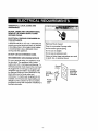 4
4
-
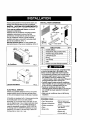 5
5
-
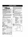 6
6
-
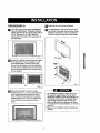 7
7
-
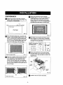 8
8
-
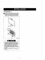 9
9
-
 10
10
-
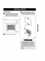 11
11
-
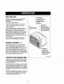 12
12
-
 13
13
-
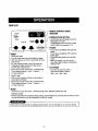 14
14
-
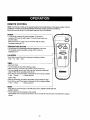 15
15
-
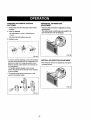 16
16
-
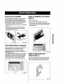 17
17
-
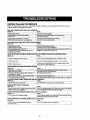 18
18
-
 19
19
-
 20
20
-
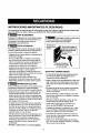 21
21
-
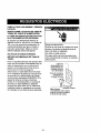 22
22
-
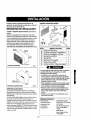 23
23
-
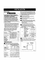 24
24
-
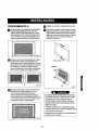 25
25
-
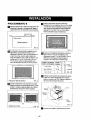 26
26
-
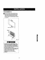 27
27
-
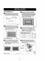 28
28
-
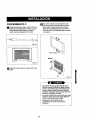 29
29
-
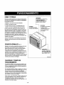 30
30
-
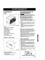 31
31
-
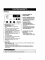 32
32
-
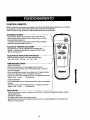 33
33
-
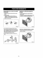 34
34
-
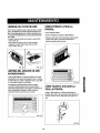 35
35
-
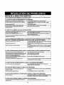 36
36
-
 37
37
-
 38
38
-
 39
39
-
 40
40


Kenmore 580.73083300 El manual del propietario
- Tipo
- El manual del propietario
- Este manual también es adecuado para
en otros idiomas
- English: Kenmore 580.73083300 Owner's manual
Artículos relacionados
-
Kenmore 580.75119500 El manual del propietario
-
Kenmore 580.73093300 El manual del propietario
-
Kenmore 580.74093400 El manual del propietario
-
-
-
-
-