
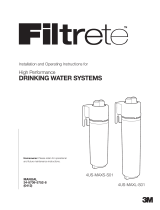
Use & Care Guide for
Homeowner: Please retain for operational
and future maintenance instructions.
4US-MAXS-S01
4US-MAXS-S01
4US-MAXL-S01
4US-MAXL-S01
USE & CARE GUIDE
34-8716-6525-2
Quick Change
UNDER SINK SINGLE
STAGE AND SINGLE STAGE
PLUS WATER FILTRATION SYSTEMS
Single Stage
Single Stage Plus
System Tested and Certied by NSF International
against NSF/ANSI Standard 42 and 53 for the
reduction of claims specied on the
Performance Data Sheet.
System Tested and Certied by NSF International
against NSF/ANSI Standard 42, 53 and 401 for
the reduction of claims specied on the
Performance Data Sheet.
This is a chemical and mechanical reduction lter.
This is a chemical and mechanical reduction lter.

2
• Read and follow Use & Care Guide before
installation and use of this system.
• Change the disposable filter cartridge at the
recommended interval; the disposable filter
cartridge MUST be replaced every 6 months
or sooner.
• Failure to replace the disposable filter cartridge at
recommended intervals may lead to reduced filter
performance and failure of the filter, causing
property damage from water leakage or flooding.
• Installation and use MUST comply with all state
and local plumbing codes.
• Protect from freezing, remove filter cartridge when
temperatures are expected to drop below 33° F
(4.4° C).
• For both 4US-MAXL-S01 and 4US-MAXS-S01: 750
gallon (2,839l) capacity and .75 (2.8 lpm) flow rate
• DO NOT install systems in areas where ambient
temperatures may go above 110° F (43.3° C).
• DO NOT install on hot water supply lines. The
maximum operating water temperature of this filter
system is 100°F (37.8°C).
SAFETY INFORMATION
Read, understand, and follow all safety information contained in these instructions prior
to installation and use of the Filtrete
™
Under Sink Single Stage (4US-MAXS-S01) and
Single Stage Plus (4US-MAXL-S01) Water Filtration Systems. Retain these instructions
for future reference.
WARNING
WARNING
NOTICE
Read entire Use & Care Guide. Failure to follow all guides and rules could cause personal
injury or property damage.
• Check with your local public works department for plumbing codes. You must follow their guidelines as you
install the water filtration system.
• Your water filtration system will withstand up to 125 pounds per square inch (psi) water pressure. If your
house water supply pressure is higher than 80 psi, install a pressure reducing valve before installing the water
filtration system.
To reduce the risk associated with choking:
• DO NOT allow children under 3 years of age to have access to small parts during the installation of this product
To reduce the risk associated with the ingestion of contaminants:
• DO NOT use with water that is microbiologically unsafe or of unknown quality without adequate disinfection
before or after the system. Systems certified for cyst reduction may be used on disinfected water that may
contain filterable cysts. EPA Establishment Number: #10350-MN-005
To reduce the risk associated with hazardous voltage due to an installer drilling through
existing electric wiring or water pipes in the area of installation:
• DO NOT install near electric wiring or piping which may be in path of a drilling tool when selecting the position
to mount the filter bracket.
To reduce the risk associated with hazardous voltage:
• If the home electrical system requires use of the cold water system as an electrical safety ground, a jumper
MUST be used to ensure a sufficient ground connection across the filter installation piping — refer installation
to qualified personnel.
To reduce the risk of physical injury:
• Depressurize system as shown in manual prior to cartridge removal.
EXPLANATION OF SIGNAL WORD CONSEQUENCES
Indicates a potentially hazardous situation, which, if not avoided, could
result in death or serious injury and/or property damage.
Indicates a potentially hazardous situation, which, if not avoided, may
result in property damage.
Intended use:
The Filtrete Single Stage (4US-MAXS-S01) and Single Stage Plus (4US-MAXL-S01) Under Sink Water
Filtration Systems are intended for use in filtering potable water and has not been evaluated for other
uses. The product is installed at the point of use and must be installed as specified in the Use & Care
Guide by a qualified professional.
NOTICE
To reduce the risk associated with property damage due to water leakage or flooding:

• DO NOT install if water pressure exceeds 125 psi (862
kPa). If your water pressure exceeds 80 psi (552 kPa),
you must install a pressure limiting valve. Contact a
plumbing professional if you are uncertain how to check
your water pressure.
• DO NOT install where water hammer conditions may
occur. If water hammer conditions exist you must
install a water hammer arrester. Contact a plumbing
professional if you are uncertain how to check for
this condition.
• Where a backflow prevention device is installed on a
water system, a device for controlling pressure due
to thermal expansion MUST be installed. Contact
a plumbing professional if you are uncertain how to
select/install/maintain a thermal expansion device.
• Where a booster pump is installed on a water system,
you MUST maintain and inspect the attached pressure
switch regularly in accordance with the booster pump
manufacturer’s instructions. Contact a plumbing
professional if you are uncertain how to maintain your
booster pump system.
• Where a booster pump is installed on a water
system, you MUST install an appropriate pressure
relief valve. Pressure relief valve must be maintained
and inspected every 6 months. Contact a plumbing
professional if you are uncertain how select/install/
maintain a pressure relief valve.
• Where a booster pump is installed on a water
system, you MUST install an appropriate pressure
regulating valve and regulate water pressure to
<80psi. Contact a plumbing professional if you
are uncertain how select/install/maintain a pressure
regulating valve.
• DO NOT use a torch or other high temperature sources
near filter system, cartridges, plastic fittings or plastic
plumbing.
• On plastic fittings, never use pipe sealant or pipe dope.
Use PTFE thread tape ONLY, pipe dope properties may
deteriorate plastic.
• Take care when using pliers or pipe wrenches to tighten
plastic fittings, as damage may occur if over tightening
occurs.
• DO NOT install in direct sunlight or outdoors.
• DO NOT install near water pipes which will be in path of
a drilling tool when selecting the position to mount the
bracket.
• Mount filter in such a position as to prevent it from
being struck by other items used in the area of
installation.
• Ensure that the location and fasteners will support the
weight of the system when installed and full of water.
• Ensure all tubing and fittings are secure and free of
leaks.
• Shut off fuel or electric power supply to water heater
after water is shut off during system installation.
IMPORTANT NOTES:
• Failure to follow instructions will void warranty.
• Allow a minimum of 2 1/2" clear space under filter to facilitate cartridge change.
• Install with the inlet and outlet ports as labeled. Make sure not to reverse connections.
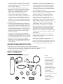
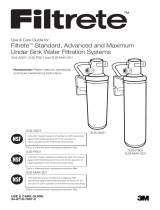
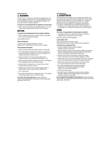
A. B.
C.
D.
G. H. I.
L. M.
J.
K.
E.
F.
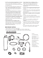
PARTS AND MATERIALS: (included)
GETTING STARTED
• Filter (A)
• Filter head assembly (B)
• Faucet with tubing, nut (C)
• Coiled tubing (D)
• Water supply line adapter (E)
• Water supply line seal (F)
• Faucet mounting shim (G)
• Faucet gasket (H)
• Decorative spacer (I)
• Decorative spacer gasket (J)
• Faucet spout (K)
• 2 mounting screws (L)
• Filter change indicator (M)
3

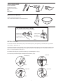
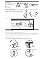
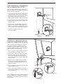
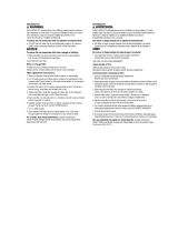
This system uses push-in fittings:
This easy-to-install system uses watertight, push-in fi ttings.
To Release Tubing:
Fig. 1
Push in collet to
release tubing.
With collet held, pull
tubing straight out.
To Attach Tubing:
Push tubing in as far
as it will go. Tubing
must be inserted past
o-ring and hit backstop.
Pull tube to ensure it is secure.
4
BEFORE YOU BEGIN:
• Remove items stored under the sink.
• Have a towel and bowl available in case dripping occurs.
TOOLS REQUIRED:
(Not included)
Two Adjustable wrenches
#2 Phillips head screwdriver
Drill
Pencil
Safety glasses
(Fig. 2) (Fig. 3)
(Fig. 4)
(Fig. 5)
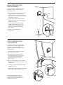
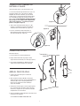
INSTALL FAUCET:
You will need: faucet with attached tubing, nut (C), faucet mounting shim (G), faucet gasket (H), decorative spacer (I), decorative
spacer gasket (J), faucet spout (K)
1. Place the faucet gasket (H), the decorative spacer (I), and the decorative spacer gasket (J) on the faucet and insert faucet tubing,
shaft and nut (C) into pre-existing soap dispenser or sprayer opening in sink. (If no opening exists, or installation is desired else-
where, a 1 1/4" opening must be made.) (Fig. 2)
2. Install faucet mounting shim (G), onto faucet shaft (Fig. 3) and hand tighten nut. (Fig. 4)
3. Insert spout (K) into faucet body (C). Hand tighten faucet spout nut. (Fig. 5)
Faucet Opening
Insert Shim
Tighten Nut Spout Insert

HOT
COLD
(Fig. 6)
(Fig. 8)
(Fig. 9)
2
1
/
2
"
(Fig. 10)
(Fig. 11)
(Fig. 7)
5
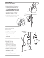
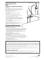
MOUNTING THE FILTER
HEAD ASSEMBLY:
You will need: Phillips screwdriver, drill, pencil,
safety glasses, filter (A), head assembly (B),
#2 mounting screws (L)
1. Choose a location to mount filter head assembly
(B). Keep in mind: Filter head should be in
a location that offers easy access for changing
filters. Leave 2 ½" of clearance below the installed
filter cartridge. (See Fig. 6)
2. Using the bracket on the head (B) as a guide,
mark the location of the two screw holes on the
wall with a pencil. (Fig. 7)
3. Fasten the head to the wall using a Phillips
screwdriver and the two mounting screws
included (L) (Fig. 8). (If preferred, use a drill
with a 1/8" size drill bit to make pilot holes
for the screws.)
4. Check to assure mounting bracket is
firmly installed.
HOT
COLD
(Fig. 6)
(Fig. 8)
(Fig. 9)
2
1
/
2
"
(Fig. 10)
(Fig. 11)
(Fig. 7)
ATTACH WATER SUPPLY
LINE ADAPTER:
You will need: Adjustable wrench (Note: Two
wrenches may be needed to adequately tighten
fittings when connecting the adapter to the
supply line), water supply line adapter (E), water
supply line seal (F)
1. Turn off the cold water supply at the shutoff
valve under the sink. (Fig. 9)
2. Place bowl under cold water connection.
Disconnect the cold water faucet hose from
the shutoff valve below using wrenches.
Leave the hose attached to the faucet
above. (Fig. 10)
3. Ensure the water supply line seal (F) is properly
inserted into female threaded portion of water supply
line adapter (E).
4. Install water supply line adapter on water supply
shut-off valve. (Fig. 11)
5. Reconnect the cold water faucet hose onto threaded
portion of water supply line adapter. (Fig. 11)
Note: If the water supply line adapter (E)
does NOT fit properly onto the end of your
shutoff valve, visit your local hardware store
to purchase the correct size.

(Fig. 12)
(Fig. 13)
(Fig. 14)
(Fig. 15)
(Fig. 16)
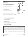
ATTACH THE FILTER:
You will need: filter (A)
1. Insert the filter (A) into the filter head (B).
2. Push filter up, then turn one quarter
of a turn to the right until it stops.
(Fig. 15)
3. When properly attached, there will
be NO gap between the filter head (B)
and the filter (A).
TURN WATER ON:
1. Turn the water back on at the
cold water shut-off valve. (Fig. 16)
2. Open dedicated faucet to flush 2 gallons
(approx. 4 minutes.) through the system
before use. Water may appear cloudy, but
will turn clear as the trapped air is released.
3. Check for leaks. If any dripping or leaking
occurs, turn cold water supply off, open both
faucets, tighten fittings and ensure that tubing is
pushed completely into fittings.
4. Activate filter change indicator according to
instructions on page 8.
YOUR SYSTEM IS NOW READY FOR USE.
ATTACH WATER
INLET/OUTLET HOSES:
You will need: 1 length of 1/4" tubing (D).
1. Insert one end of the length of 1/4" tubing (D) into
the push-in fitting on the side of the water supply
line adapter (E) you just installed. Push the tubing
in firmly as far as it will go to ensure a watertight fit.
(Fig. 12) Important Note: Water may leak if the tube
is not pushed in completely. (See “push-in fittings”
explanation on Pg. 3. Fig. 1)
2. Take the other end of the same 1/4" tubing (D)
and insert into the right (inlet) side of the filter
head assembly (B). (Fig. 13)
3. Insert the end of the faucet tubing into the left (outlet)
side of the filter head assembly (B). (Fig. 14)
6

(Fig. 15)
(Fig. 16)
7
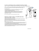
FILTER
REPLACEMENT
INSTRUCTIONS:
NOTICE
To reduce the risk associated with property damage due to water
leakage or flooding, replace filter every six months or sooner.
NOTE: You do NOT need to shut off your water supply
when changing your filter. The system will automatically
shut off the water supply while the filter is being changed.
REPLACING FILTER
1. Turn filter to the left until it releases from the filter head.
2. Gently pull filter down to remove.
3. Insert new filter into filter head, turn one quarter of a
turn to the right until it stops.
4. Open dedicated faucet to flush 2 gallons (approx. 4 minutes)
through the system before use. Water may start cloudy,
but will turn clear as the trapped air is released.
5. Activate filter change indicator according to instructions on page 8.
Replacement filters can be purchased at original point of sale.
Available filters include 4US-MAXS-F01 and 4US-MAXL-F01.
TROUBLESHOOTING GUIDE
Water Leaks at Push-In Connections:
Push tubing in as far as it will go. If leaking continues, shut off water at
the shut off valve, depressurize and remove water line by pushing in on the connector
collar while pulling the tubing away. Inspect tubing for cracks and
scratches. If tubing is cracked or scratched, simply cut that portion away
and reinsert tubing into push-in fitting.
Water Does Not Flow from the Drinking Water System Faucet:
Check to see if the main water line valve is open,
allowing water to flow to the filter.
Water Appears Cloudy or Air Comes Out of the Drinking Water System Faucet:
Flush filter for an additional full five (5) minutes to remove any carbon fines or
trapped air in the filter and water lines.
For more information or questions
Visit www.lowes.com or call 1-800-388-3458
Distributed by:
3M, Constructionand Home Improvement Markets Division
3M Center, St. Paul, MN 55144-1000
1-800-388-3458
3M and Filtrete are trademarks of 3M Company.
NSF is a trademark of NSF International.
Timestrip is the registered trademark of Timestrip UK Limited.
All other trademarks are the property of their respective owners.
© 2015, 3M. All rights reserved.
LIMITED WARRANTY:
3M warrants this Product will be free from defects in material and manufacture for one (1) year from the date of purchase. This warranty does not cover failures
resulting from abuse, misuse, alteration or damage not caused by 3M or failure to follow installation and use instructions. No warranty is given as to the
service life of any filter cartridge or membrane as it will vary with local water conditions and water consumption. 3M MAKES NO OTHER WARRANTIES OR
CONDITIONS, EXPRESS OR IMPLIED, INCLUDING, BUT NOT LIMITED TO, ANY IMPLIED WARRANTY OR CONDITION OF MERCHANTABILITY OR FITNESS
FOR A PARTICULAR PURPOSE OR ANY IMPLIED WARRANTY OR CONDITION ARISING OUT OF A COURSE OF DEALING, CUSTOMER OR USAGE OF
TRADE. If the Product fails to satisfy this Limited Warranty during the warranty period, 3M will replace the Product or refund your Product purchase price.
This warranty does not cover labor. The remedy stated in this paragraph is Customer’s sole remedy and 3M’s exclusive obligation.
This warranty gives you specific legal rights, and you may have other rights which may vary from state to state, or country to country. For any warranty questions,
please call 1-800-388-3458 or mail your request to: Warranty Claims, 3M, Customer Care Center, 3M Center 225-3S-06, St. Paul, MN 55144-1000. Proof of
purchase (original sales receipt) must accompany the warranty claim, along with a complete description of the Product, model number and alleged defect.
LIMITATION OF LIABILITY:
3M will not be liable for any loss or damage arising from this 3M Product, whether direct, indirect, special, incidental, or consequential, regardless of the legal
theory asserted, including warranty, contract, negligence or strict liability. Some states and countries do not allow the exclusion of limitation of incidental or
consequential damages, so the above limitation or exclusion may not apply to you.

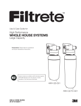
8
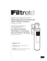
Push to activate
Solid line will appear
and begin to ll within
a couple of minutes
6 months
Replace the lter
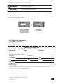
Mail Product Registration Form to:
3M, Customer Care Center
3M Center 225-3S-06
St. Paul, MN 55144-1000
Product Name: Model: Date Code:
Dr. □ Mr. □ Ms. □ Mrs. □ Miss □
First Name Last Name
Street Address Apt. #
City State Zip Code
Email Address
*
Phone Number
Date of Purchase
PRODUCT REGISTRATION FORM
3M, Construction and Home Improvement Markets Division
3M Center, St. Paul, MN 55144-1000
1-800-388-3458
*Submitting your email address is optional. This information will be used only to provide you with information about 3M products and in
accordance with 3M’s privacy policy found at www.3M.com/privacy.
1. Press filter change indicator bubble firmly to activate.
2. Tape or place the filter change indicator on the system housing or in a noticeable location, such as your refrigerator door.
3. Do not place filter change indicator in refrigerator.
ACTIVATE FILTER CHANGE INDICATOR
To reduce the risk associated with choking, do not allow children under 3 years of age
access to the filter change indicator.
To reduce the risk of property damage, do not puncture filter change indicator bubble.
The non-toxic fluid may stain certain materials.
WARNING
NOTICE

Guía de uso y cuidado para
Propietario: Conserve para consultar las instrucciones
de operación y mantenimiento en el futuro.
Cambio rápido
SISTEMAS DE FILTRADO DE AGUA SINGLE
STAGE Y SINGLE STAGE
PLUS PARA BAJO FREGADEROS
Sistema evaluado y certicado por la NSF International
según los estándares 42 y 53 de NSF/ANSI para la
reducción de las declaraciones especicadas en la
hoja de datos de rendimiento.
Sistema evaluado y certicado por la NSF International
según los estándares 42, 53 y 401 de NSF/ANSI para la
reducción de las declaraciones especicadas en la
hoja de datos de rendimiento.
Este es un ltro de reducción química y mecánica.
Este es un ltro de reducción química y mecánica.
4US-MAXS-S01
4US-MAXL-S01
4US-MAXS-S01
4US-MAXL-S01
USE & CARE GUIDE
34-8716-6525-2
USE & CARE GUIDE
34-8716-6525-2
Single Stage
Single Stage Plus

2
• Lea y siga la Guía de uso y cuidados antes de
instalar y usar este sistema.
• Reemplace el cartucho del filtro desechable según
los intervalos recomendados; el cartucho del filtro
descart able se DEBERÁ reemplazar cada 6 meses
o antes.
• Si no reemplaza el cartucho de filtro desechable
según los intervalos recomendados, puede disminuir
el rendimiento del filtro y provocar fallas en el filtro,
causando daños a la propiedad por pérdidas de
agua o inundación.
• La instalación y el uso DEBEN cumplir con todos los
códigos de plomería locales y estatales.
• Proteja del congelamiento, retire el cartucho del filtro
cuando se espera que la temperatura caiga por de-
bajo de 33 °F (4,4 °C).
• Para los modelos 4US-MAXL-S01 y 4US-MAXS-S01:
750 galones (2 839 l) de capacidad y .75 (2,8 lpm) de
velocidad de flujo.
• NO instale sistemas en áreas donde las temperaturas
ambiente puedan superar los 110 °F (43,3 °C).
• NO instale en líneas de suministro de agua caliente.
La máxima temperatura del agua en funcionamiento
para este sistema de filtro es de 100 °F (37,8 °C).
• NO instale si la presión del agua supera los 862 kPa.
INFORMACIÓN DE SEGURIDAD
Lea, comprenda y respete toda las información de seguridad contenida en estas instrucciones antes de
instalar y usar los sistemas de filtrado de agua Single Stage (4US-MAXS-S01) y Single Stage Plus
(4US-MAXL-S01) Filtrete
™
para bajo fregaderos. Conserve estas instrucciones para futuras consultas.
ADVERTENCIA
ADVERTENCIA
AVISO
Lea el guía de uso y cuidado
en su totalidad. El incumplimiento de cualquier guía y medida
puede causar lesiones o daños a la propiedad.
• Consulte los códigos de plomería en el departamento local de obras públicas. Debe seguir las pautas que
le provean al instalar el sistema de filtrado de agua.
• Su sistema de filtrado de agua resistirá una presión de agua de hasta 862 kPa. Si la presión de suministro
de agua de su casa es mayor a 80 psi, instale una válvula reductora de presión antes de instalar el sistema
de filtrado de agua.
Para reducir el riesgo asociado con asfixia:
• NO permita que niños menores de 3 años de edad tengan acceso a las piezas pequeñas durante la
instalación de este producto.
Para reducir el riesgo asociado con la ingesta de contaminantes:
•
NO use la unidad con agua microbiológicamente no apta para el consumo o de calidad desconocida sin una
adecuada desinfección previa o posterior al sistema. Los sistemas certificados para la reducción de quistes se
pueden utilizar con agua desinfectada que podría tener quistes filtrables. Establecimiento EPA N.° 10350-MN-005
Para reducir el riesgo asociado con voltajes peligrosos que se presenten por taladrar
cableado eléctrico o tuberías de agua existentes en el área de la instalación:
•
NO instale el producto cerca de cableado eléctrico o de tuberías que pudieran estar en el camino del taladro al
seleccionar la posición de montaje del soporte del filtro.
Para reducir el riesgo asociado con voltajes peligrosos:
•
Si el sistema eléctrico del hogar requiere el uso de un sistema de agua fría como protección eléctrica a tierra,
DEBERÁ usar un puente para garantizar una conexión a tierra suficiente en toda la tubería donde se instala el filtro;
asigne la instalación a personal calificado.
Para reducir el riesgo de lesiones físicas:
•
Despresurice el sistema como se muestra en el manual antes de retirar el cartucho.
EXPLICACIÓN DE LAS CONSECUENCIAS DE LAS PALABRAS DE SEÑALIZACIÓN
Indica una situación potencialmente peligrosa, la cual, si no se evita,
puede resultar en muerte o lesiones serias y/o daños a la propiedad.
Indica una situación potencialmente peligrosa, la cual, si no se evita,
puede resultar en daños a la propiedad.
Uso intencionado:
Los sistemas de filtrado de agua Single Stage (4US-MAXS-S01) y Single Stage Plus (4US-MAXL-S01)
para bajo fregaderos Filtrete están diseñados para filtrar agua potable y no se han evaluado para otros
usos. El producto se instala en el punto de servicio y debe ser instalado por un profesional calificado
según lo especificado en la Guía de uso y cuidado.
AVISO
Para reducir el riesgo asociado con los daños materiales debidos a pérdidas de agua
o inundación:

A. B.
C.
D.
G. H. I.
L. M.
J.
K.
E.
F.
ANOTACIONES IMPORTANTES:
• No seguir las instrucciones resultará en la anulación de la garantía.
• Deje un mínimo de 2½” de espacio debajo del filtro para facilitar el cambio del cartucho.
• Instale con los puertos de entrada y salida según se indica en la etiqueta.
Asegúrese de no reversar las conexiones.
PARTES Y MATERIALES: (incluidos)
PARA COMENZAR:
• Filtro (A)
• Cabeza del filtro (B)
• Grifo con tubo, tuerca (C)
• Tubería enroscada (D)
• Adaptador para la línea de
suministro de agua (E)
• Sellador de la línea de
suministro de agua
(F)
•
Calce para montar el grifo (G)
• Empaque (empaquetadura)
para el grifo (H)
•
Separador decorativo (I)
•
Junta de separador decorativo (J)
• Pico del grifo (K)
• 2 tornillos de montaje (L)
• Indicador de cambio
del filtro (M)
Si la presión de agua es mayor a 552 kPa, debe
instalar una válvula limitadora de presión.Contacte a
un plomero profesional si no está seguro de cómo
verificar la presión del agua.
• NO instale donde podría haber condiciones de
golpes con un ariete. Si existen tales condiciones,
debe instalar un supresor de golpes de ariete.
Contacte a un plomero profesional si no está
seguro de cómo verificar esta condición.
• Si hay un dispositivo de prevención de retorno
instalado en un sistema de agua, se DEBE instalar
un dispositivo controlador de presión debida a la
expansión térmica. Comuníquese con un plomero
profesional si no está seguro de cómo seleccionar
instalar/realizar el mantenimiento del dispositivo de
expansión térmica.
• Cuando haya una bomba elevadora de presión en
un sistema de agua, DEBE mantener e inspeccionar
regularmente el interruptor de presión adjunto de
conformidad con las instrucciones del fabricante de
la bomba elevadora de presión. Comuníquese con
un plomero profesional si no está seguro de cómo
realizar el mantenimiento del sistema de bomba
elevadora de presión.
• Cuando haya una bomba elevadora de presión
instalada en un sistema de agua, DEBE instalar una
válvula de alivio de presión adecuada. La válvula de
alivio de presión debe mantenerse e inspeccionarse
cada 6 meses. Comuníquese con un plomero
profesional si no está seguro de cómo seleccionar/
instalar/realizar el mantenimiento de la válvula de
alivio de presión.
• Cuando haya una bomba elevadora de presión
instalada en un sistema de agua, DEBE instalar una
válvula reguladora de presión adecuada y regular
la presión de agua a <80 psi. Comuníquese con
un plomero profesional si no está seguro de cómo
seleccionar/instalar/realizar el mantenimiento de la
válvula reguladora de presión.
• NO use un soplete ni otra fuente de alta temperatura
cerca del sistema de filtro, los cartuchos, los
accesorios plásticos o las tuberías de plástico.
•
Nunca aplique sellador de tuberías o grasa para
tuberías sobre los accesorios plásticos. Use
solamente cinca para roscado de PTFE, ya que las
propiedades de la grasa podrían deteriorar el plástico.
• Tenga cuidado cuando use pinzas o llaves para
tuberías para ajustar los accesorios plásticos, ya que
podría producir daños si los ajusta en exceso.
• NO instale bajo luz solar directa ni en exteriores.
• NO instale el producto cerca de tuberías de agua
que pudieran estar en el camino de un taladro al
seleccionar la posición de montaje del soporte.
• Monte el filtro en una posición tal que prevenga que
se atasque con otros elementos usados en el área
de instalación.
• Asegúrese de que la ubicación y las sujeciones
puedan soportar el peso del sistema cuando esté
instalado y lleno de agua.
• Asegúrese de que todas las tuberías y accesorios
están seguros y de que no haya pérdidas.
• Corte el suministro de combustible o de alimentación
eléctrica al calentador de agua después de cerrar el
suministro de agua durante la instalación del sistema.
3

4
(Figura 2) (Figura 3)
(Figura 4)
(Figura 5)
INSTALE EL GRIFO:
Necesitará: grifo con tubería adjunta, tuerca (C), taco para el montaje del grifo (G),
1. Coloque la junta del grifo (H), el separador decorativo (I) y la junta de separador decorativo (J) sobre el grifo e introduzca la tubería
del grifo, el eje y la tuerca (C) en la abertura del dispensador o pulverizador de jabón preexistente en el fregadero. (Si no hubiera
abertura, o si deseara instalarlo en otro lugar, deberá hacer una abertura de 6,35 mm.) (Fig. 2)
2. Instale el calce para montar el
grifo (G) en el eje del grifo (Figura 3) y apriete la tuerca. (Figura 4)
3. Inserte el pico del grifo (K) en el cuerpo del grifo (C). Apriete la tuerca del pico del grifo a mano. (Figura 5)
Abertura para el grifo Inserte el calce
Apriete la tuerca Inserte el pico
Este sistema utiliza accesorios para aplicar presión:
Este sistema fácil de instalar utiliza accesorios impermeables para aplicar presión.
Para soltar
las tuberías:
Fig. 1
Empuje el anillo de
guía hacia adentro
para soltar el tubo.
Sosteniendo el anillo
de guía, hale el tubo
directamente hacia afuera.
Para conectar
las tuberías:
Empuje el tubo hacia
adentro hasta donde se lo
permita. El tubo debe ser
insertado más allá del anillo “O”
y parar contra el respaldo. Hale del
tubo para asegurarse de que esté fijado.
ANTES DE COMENZAR:
• Remueva los elementos que tenga almacenados debajo del fregadero.
• Tenga una toalla y un balde disponibles en caso de que haya goteos.
HERRAMIENTAS
REQUERIDAS: (no incluidas)
Dos llaves inglesas ajustables
Destornillador (desarmador) Phillips #2
Taladro
Lápiz
Gafas de seguridad

HOT
COLD
(Figura 6)
(Figura 8)
(Figura 9)
2
1
/
2
"
(Figura 10)
(Figura 11)
(Figura 7)
5
INSERTE EL ADAPTADOR DE LA
LÍNEA DE SUMINISTRO DE AGUA:
Usted necesitará: llave inglesa ajustable (nota: es posible que
necesite dos llaves inglesas para apretar las conexiones
adecuadamente al conectar el adaptador a la línea de suminis-
tro de agua), adaptador de la línea de suministro de agua (E),
sellador de la
línea
de suministro de agua (F).
1. Apague el suministro de agua fría desde la válvula que
se encuentra debajo del fregadero. (Figura 9)
2. Coloque una taza debajo de la conexión de agua fría.
Desconecte la tubería del grifo de agua fría de la
válvula de paso de agua que hay debajo, utilizando
las dos llaves inglesas. Deje el tubo conectado al grifo
arriba. (Figura 10)
3. Asegúrese de que el sellador de la línea de suminis-
tro de agua (F) esté debidamente introducido en la
posición hembra roscada del adaptador de la línea de
suministro de agua (E).
4. Instale el adaptador de suministro de agua en la válvula
de paso de agua (Figura 11)
5. Vuelva a conectar el tubo del grifo de agua fría en la
porción guiada del adaptador de la línea de suministro
de agua. (Figura 11)
Nota: si el adaptador de la línea de suministro de agua (E)
no cabe apropiadamente en el terminal de su válvula de
paso de agua, visite su almacén de ferretería y compre el
tamaño correcto.
HOT
COLD
(Figura 6)
(Figura 8)
(Figura 9)
2
1
/
2
"
(Figura 10)
(Figura 11)
(Figura 7)
PARA MONTAR EL ENSAMBLAJE
DE LA CABEZA DEL FILTRO:
Usted necesitará: destornillador Phillips, taladro, lápiz,
gafas de seguridad, filtro (A), ensamblaje de la cabeza del
filtro (B), tornillos de montaje #2 (L)
1. Escoja una ubicación para montar el ensamblaje de la
cabeza del filtro (B). Tenga en cuenta: la cabeza del
filtro debe estar en una ubicación que facilite el acceso
para el cambio del filtro. Deje un espacio de 2½”
debajo del cartucho del filtro al instalar. (Ver Figura 6)
2. Usando el soporte en la cabeza (B) como guía, marque
la ubicación de los dos huecos para los tornillos en la
pared con un lápiz.
3. Instale la cabeza en la pared usando el destornillador
Phillips y los dos tornillos de montaje incluidos (L)
(Figura 8). (Si lo prefiere, use un taladro con una broca
de 1/8” para hacer agujeros piloto para los tornillos).
4. Verifique que el soporte del montaje esté
firmemente instalado.

(Figura 15)
(Figura 16)
(Figura 12)
(Figura 13)
(Figura 14)
CONECTE LAS TUBERÍAS DE
ENTRADA Y SALIDA:
Usted necesitará: 10 pies (3 m) de tubería de ¼” (D).
1. Inserte una punta del largo de tubería de ¼” (D) en la
conexión de empuje que se encuentra en el lado de
adaptador de la línea de suministro (E) que acaba de
instalar. Empuje el tubo firmemente hacia adentro hasta
que se detenga para lograr una conexión a prueba de
agua. (Figura 12) Aviso importante: pueden presentarse
fugas de agua si no se empuja el tubo completamente.
(Vea la explicación de los “accesorios para aplicar
presión” en la página 3 Figura 1)
2. Tome el otro extremo del mismo tubo de ¼” (D) e
insértelo en el lado derecho (punto de entrada) del
ensamblaje de la cabeza del filtro (B). (Figura 13)
3. Inserte el extremo de la tubería del grifo en el
lado izquierdo (punto de salida) del ensamblaje
de la cabeza del filtro (B). (Figura 14)
6
CONECTE EL FILTRO:
Necesitará: filtro (A)
1. Inserte el filtro (A) en la cabeza del filtro (B).
2.
Empuje el filtro hacia arriba, luego haga un cuarto
de giro hacia la derecha hasta que se detenga. (Figura 15)
3. AL conectarlo apropiadamente, NO deberá quedar
espacio entre la cabeza del filtro (B) y el filtro(A).
ABRA EL PASO DE AGUA:
1. Vuelva a abrir el paso de agua en la válvula de
paso de agua fría.
2. Abra el grifo del sistema de filtrado y deje pasar 2
galones de agua a través del sistema (aproximadamente
4 minutos) antes del uso. El agua puede parecer
turbia, pero se volverá más clara a medida que
salga el aire atrapado.
3. Verifique que no haya fugas. Si ocurren fugas o goteos,
cierre el paso de agua, abra ambos grifos, apriete las
conexiones y asegúrese de que el tubo esté insertado
completamente en las conexiones.
4. Active el indicador de cambio del filtro de acuerdo con las
instrucciones de la página 8.
SU SISTEMA ESTÁ AHORA LISTO PARA USO.

7
Distribuido por:
3M, Construction Home Improvement Markets Division
3M Center, St. Paul, MN 55144-1000
1-800-388-3458
GUÍA PARA SOLUCIÓN DE PROBLEMAS
Hay fugas de agua en las conexiones:
Empuje el tubo hasta adentro, hasta donde se lo permita. Si las fugas continúan,
cierre el paso de agua en la válvula de suministro, despresurice y remueva el tubo
empujando el anillo de guía y halando del tubo hacia afuera al mismo tiempo.
Inspeccione el tubo para verificar que no tenga grietas o rajaduras.
Si el tubo tiene grietas o rajaduras, simplemente corte esa sección y reinserte
el tubo en el anillo de guía.
El agua no fluye del grifo del sistema de agua potable:
Revise para verificar que la válvula de paso de agua esté abierta, de manera
que fluya agua el filtro.
El agua sale turbia o hay aire saliendo del grifo del sistema de agua potable:
Deje pasar agua a través del filtro por lo menos cinco (5) minutos más para remover
cualquier rastro de carbón o aire atrapados en las líneas de agua y del filtro.
Para más información o preguntas
Visite www.lowes.com o llame al 1-800-388-3458.
GARANTÍA LIMITADA:
3M garantiza que este producto estará libre de defectos en materiales y manufactura por un (1) año a partir de la fecha de compra. Esta garantía no cubre
fallas resultantes del abuso, mal uso, alteraciones o daños no realizados por 3M o por no seguir las instrucciones de uso e instalación. No se otorgan garantías
respecto a la vida útil de ningún cartucho/repuesto de filtro ni sus membranas, ya que éstas pueden variar según las condiciones locales del agua y la cantidad
de agua consumida. 3M NO OTORGA NINGUNA OTRA GARANTÍA O CONDICIÓN, EXPRESA O IMPLÍCITA, INCLUYENDO, PERO NO LIMITADA A CUALQUIER
GARANTÍA IMPLÍCITA O CONDICIÓN DE COMERCIALIZACIÓN O IDONEIDAD PARA UN PROPÓSITO PARTICULAR O CUALQUIER GARANTÍA IMPLÍCITA O
CONDICIÓN EMERGENTE DE UN CURSO DE GESTIÓN, DEL CLIENTE O USO DE COMERCIO. Si el producto no satisface esta garantía limitada durante el
periodo de garantía, 3M reemplazará el producto o reembolsará el precio de compra del producto. Esta garantía no cubre el costo de mano de obra. El remedio
declarado en este párrafo es el remedio único para el consumidor y la obligación exclusiva de 3M.
Esta garantía le otorga derechos legales específicos y usted puede tener otros derechos que varían de estado a estado o de país a país. Para cualquier
pregunta relacionada con la garantía, por favor llame al 1-800-388-3458 o envíe su solicitud a: Warranty Claims, 3M, Customer Care Center, 3M Center 225-
3S-06, St. Paul MN 55144-1000. El comprobante de compra (recibo original de compra) debe acompañar la solicitud de garantía, junto con una descripción
completa del producto, el número de modelo y el defecto presunto.
LIMITACIÓN DE RESPONSABILIDAD:
3M no será responsable de ninguna pérdida o daños resultantes de este producto 3M, ya sean directos, indirectos, especiales, incidentales o consecuentes,
independientemente de la teoría legal afirmada, incluyendo responsabilidad de garantía, contractual, negligente o estricta. Algunos estados o países no
permiten la exclusión de la limitación de daños incidentales o consecuentes, así que la limitación anterior podría no aplicar a usted.
(Figura 15)
(Figura 16)
INSTRUCCIONES PARA
REEMPLAZAR EL FILTRO:
AVISO:
Para reducir el riesgo asociado con el daño a la propiedad debido
a las fugas de agua o al anegamiento, reemplace el filtro cada seis
meses o antes.
NOTA: usted NO necesita apagar el suministro de agua Para cambiar
el filtro. El sistema apagará el suministro de agua automáticamente
cuando detecte que el filtro se está cambiando.
PARA REEMPLAZAR EL FILTRO
1. Gire el filtro hacia la izquierda hasta que se suelte del la
cabeza del filtro.
2. Hale el filtro con cuidado hacia abajo para removerlo.
3. Inserte un filtro nuevo en la cabeza del filtro, gírelo un cuarto
de giro hacia la derecha hasta que se detenga.
4. Abra el grifo dedicado para dejar pasar 2 galones de agua (unos
4 minutos) a través del sistema antes de usarlo. El agua podría
comenzar a salir turbia, pero se volverá transparente a medida que
se libera el aire atrapado.
5. Active el indicador de cambio del filtro de acuerdo con las
instrucciones en la página 8.
Llos filtros de reemplazo pueden ser comprados en el punto original
de compra del filtro. Los filtros disponibles incluyen el
4US-MAXS-F01 y el 4US-MAXL-F01.
Filtrete y 3M son marcas comerciales de 3M Company.
NSF es una marca comercial de NSF International.
Timestrip es la marca registrada de Timestrip UK Limited.
Todas las demás marcas comerciales son la propiedad de sus respectivos dueños.
© 2015, 3M. Todos los derechos reservados.

8
Presione para activar
Una línea sólida aparecerá
y se comenzará a llenar
dentro de un par de minutos
6 meses
Reemplace el ltro
Envíe el formato de registro del producto a:
3M, Customer Care Center
3M Center 225-3S-06
St. Paul, MN 55144-1000
Nombre del producto: Modelo: Código de fecha en el filtro:
Dr. Sr. Sra. Srta.
Nombre Apellido
Dirección Apto. #
Ciudad Estado Código postal
Dirección de email*
Número telefónico
Fecha de compra
FORMATO DE REGISTRO DEL PRODUCTO
3M, Construction and Home Improvement Markets Division
3M Center, St. Paul, MN 55144-1000
1-800-388-3458
*Otorgar su dirección de email es opcional. Esta información será usada únicamente para proveerle información acerca de los productos de 3M, de
acuerdo con la política de privacidad de 3M que se encuentra en www.3M.com/privacy.
1. Presione firmemente la burbuja indicadora de cambio del filtro para activarla.
2. Coloque o pegue con cinta adhesiva el indicador de cambio del filtro en la carcasa del sistema o en una
ubicación notable, tal como la puerta de su refrigerador.
3. No coloque el indicador de cambio del filtro adentro de su refrigerador.
ACTIVE EL INDICADOR DE CAMBIO DEL FILTRO
Para reducir el riesgo asociado con asfixia, no permita que los niños menores de 3 años
tengan acceso al indicador de cambio del filtro.
Para reducir el riesgo de daños a la propiedad, no perfore la burbuja indicadora de cambio
del filtro. El fluido (no tóxico) puede manchar ciertos materiales.
ADVERTENCIA
PRECAUCÍON
-
 1
1
-
 2
2
-
 3
3
-
 4
4
-
 5
5
-
 6
6
-
 7
7
-
 8
8
-
 9
9
-
 10
10
-
 11
11
-
 12
12
-
 13
13
-
 14
14
-
 15
15
-
 16
16


En otros idiomas
- English: Filtrete 4US-MAXS-F01 User guide
Documentos relacionados
-
 Filtrete 3US-PF01 Instrucciones de operación
-
 Filtrete 4US-MAXS-S01 Guía de instalación
-
 Filtrete 3US-MAX-S01 Manual de usuario
-
 Filtrete 4WH-QCTO-F01 Manual de usuario
-
 Filtrete 5627902 WF SYS 4WH-QCTO-S01 CTO Instrucciones de operación
-
 Filtrete 3WH-STDCW-F02 Instrucciones de operación
-
 Filtrete 4WH-HDGAC-F01 Instrucciones de operación
-
 Filtrete 3US-AS01 Instrucciones de operación


