
EN
How to Use This Reference Manual
The CL5/CL3/CL1 Reference Manual (this document) allows you
to search for terms and take advantage of links in the text.
Searching for terms
To search for a term, use the search function of the software
you’re using to view this document.
If you’re using Adobe Reader, enter the term in the search box
and press the <Enter> key of your computer keyboard to search
for occurrences of that term.
Displaying the next/previous view
If you’re using Adobe Reader, you can jump to the previous/next
view in your viewing history. This is a convenient way to jump back
to the previous page after you’ve used a link to jump to a different
page.
Using the Function Tree
A function tree for the CL series is provided on page 4 and
following. You can use this function tree to find the page that
explains an on-screen display or function.
Reference Manual

Contents
Reference Manual
2
Contents
How to Use This Reference Manual .......................................................................... 1
Function Tree ............................................................................ 4
SELECTED CHANNEL section ...................................................... 6
Operations in the SELECTED CHANNEL Section ....................................................... 6
Centralogic section ................................................................. 13
Operations in the Centralogic section .................................................................... 13
Input and output patching..................................................... 18
CL console internal patching and Dante audio network patching .......................... 18
Changing the input patching ................................................................................ 19
Changing the output patching .............................................................................. 20
Inserting an external device into a channel ............................................................ 23
Directly outputting an INPUT channel ................................................................... 26
Input channels ........................................................................ 28
Signal flow for input channels................................................................................ 28
Specifying the channel name/icon ......................................................................... 29
HA (head amp) settings ......................................................................................... 31
Sending the signal from an input channel to the STEREO/MONO bus ................... 37
Added pan function (Monaural input channels only) ............................................. 40
Sending a signal from an input channel to a MIX/MATRIX bus .............................. 42
Channel name display indication ........................................................................... 46
Correcting delay between channels (Input Delay).................................................. 47
Surround output for input channels....................................................................... 50
Channel library operations..................................................................................... 54
OUTPUT channels.................................................................... 55
Signal flow for output channels ............................................................................. 55
Specifying the channel name/icon ......................................................................... 56
Sending signals from MIX channels to the STEREO/MONO bus ............................. 57
Sending signals from MIX channels and STEREO/MONO channels to
MATRIX buses............................................................................................. 59
Correcting delay between channels (Output Delay)............................................... 62
Channel library operations..................................................................................... 63
EQ and Dynamics ..................................................................... 64
Using EQ ................................................................................................................ 64
Using dynamics ...................................................................................................... 67
Using the EQ/Dynamics libraries............................................................................. 70
Channel Job ............................................................................. 71
DCA group............................................................................................................. 71
DCA Roll-out function ............................................................................................ 74
Mute group............................................................................................................ 76
Using the Recall Safe function................................................................................. 79
Channel Link function ............................................................................................ 82
Copying, moving, or initializing a channel.............................................................. 87
About Mix Minus.................................................................................................... 91
Scene memory ......................................................................... 92
Storing and recalling scenes ................................................................................... 92
Editing scene memories.......................................................................................... 97
Using the Global Paste function.............................................................................. 99
Using the Focus Recall function ............................................................................ 102
Using the Fade function........................................................................................ 103
Outputting a control signal to an external device in tandem with scene recall
(GPI OUT) ................................................................................................. 105
Playing back an audio file that links to a scene recall............................................. 106
Using Preview mode............................................................................................. 108
Monitor and Cue functions ................................................... 109
Using the Monitor function .................................................................................. 110
Using the Cue function......................................................................................... 116
Talkback and Oscillator......................................................... 125
Using Talkback ..................................................................................................... 125
Using the Oscillator function ................................................................................ 127
Meters.................................................................................... 130
Operations in the METER screen ........................................................................... 130
Using an MBCL meter bridge (optional) on the CL3 or CL1 console ..................... 134
Graphic EQ, Parametric EQ, Effects, and PREMIUM RACK..... 135
About the virtual rack ........................................................................................... 135
Virtual rack operations.......................................................................................... 136
Graphic EQ operations ......................................................................................... 139
About AUTOMIXER............................................................................................... 146
Editing the internal effects .................................................................................... 148
Effects and tempo synchronization ....................................................................... 155

Contents
Reference Manual
3
Using the Premium Rack...................................................................................... 156
Using the graphic EQ, parametric EQ, effect, and Premium Rack libraries ............ 166
I/O devices and external head amps .................................... 167
Using an I/O device ............................................................................................. 167
Remotely controlling an R series unit ................................................................... 169
Third-party equipment’s HA control function....................................................... 173
Remotely controlling an amp............................................................................... 175
Remotely controlling WIRELESS unit..................................................................... 176
Using an external head amp ................................................................................ 178
MIDI....................................................................................... 183
MIDI functionality on the CL series console.......................................................... 183
Basic MIDI settings .............................................................................................. 183
Using program changes to recall scenes and library items.................................... 186
Using control changes to control parameters....................................................... 188
Using parameter changes to control parameters .................................................. 190
Recorder................................................................................ 191
About the USB memory recorder ......................................................................... 191
Assigning channels to the input/output of the recorder ....................................... 191
Recording audio to a USB flash drive.................................................................... 193
Playing back audio files from a USB flash drive ..................................................... 195
Editing the title list............................................................................................... 196
Recording or playing back using a computer DAW .............................................. 197
Using the CL console with Nuendo Live............................................................... 200
Setup ..................................................................................... 204
About the SETUP screen....................................................................................... 204
User settings ........................................................................................................ 206
Preferences .......................................................................................................... 213
USER DEFINED keys ............................................................................................. 215
Functions that can be assigned to USER DEFINED keys ........................................ 217
USER DEFINED knobs........................................................................................... 222
Functions that can be assigned to USER DEFINED knobs ...................................... 223
Assignable encoders ............................................................................................ 225
Functions that can be assigned to the assignable encoders .................................. 226
GAIN/PAN/ASSIGN knob (assignable encoder) functions ..................................... 227
Custom fader bank .............................................................................................. 227
Master fader ........................................................................................................ 228
Custom fader bank functions ............................................................................... 229
Console Lock ....................................................................................................... 229
Saving and loading setup data to and from a USB flash drive............................... 230
Formatting a USB flash drive................................................................................ 236
Word clock and slot settings................................................................................. 237
Using cascade connections ................................................................................... 239
Basic settings for MIX buses and MATRIX buses.................................................... 243
Switching the entire phantom power supply on/off.............................................. 244
Specifying the brightness of the touch screen, LEDs, channel name displays,
and lamps ................................................................................................. 244
Setting the date and time of the internal clock ..................................................... 245
Setting the network address ................................................................................. 245
Dante audio network settings ............................................................................... 246
Using GPI (General Purpose Interface) .................................................................. 257
Help function......................................................................... 263
Loading a Help/text file from a USB flash drive ..................................................... 263
Viewing Help........................................................................................................ 263
Using USER DEFINED keys to recall Help directly................................................... 264
Other functions ..................................................................... 265
Initializing the unit to factory default settings ....................................................... 265
Adjusting the detection point of the touch screen (Calibration function) .............. 265
Adjusting the faders (Calibration function) ........................................................... 266
Fine-tuning the input and output gain (Calibration function) ............................... 266
Adjusting the channel color (Calibration function)................................................ 268
Adjusting the brightness of the channel name display .......................................... 268
Adjusting the contrast of the channel name display.............................................. 269
Initializing the console settings and Dante audio network settings........................ 269
Update procedure for NAME SUB CPU firmware................................................... 270
Update function to Dante firmware ...................................................................... 270
Warning/Error Messages ...................................................... 271
Index...................................................................................... 274

Function Tree
Reference Manual
4
Function Tree
Page numbers in parentheses ( ) are the page numbers of the
Owner’s Manual(booklet).
Main
SELECTED CHANNEL 6
OVERVIEW 14
FUNCTION ACCESS AREA (18)
CHANNEL PARAMETER
PATCH/NAME 20, 30, 56
GAIN/PATCH 32
1ch 32
8ch 33
CH1-48 35
CH49-72/ST IN 35
OUTPUT
Indication only
INPUT DELAY 47
8ch 47
CH1-48 48
CH49-72/ST IN 48
DELAY SCALE 47
INSERT/DIRECT OUT 24
1ch 24, 26
8ch 25, 27
HPF/EQ 64
1ch 64
8ch 66
CH1-48 66
CH49-72/ST IN 66
OUTPUT 66
DYNAMICS 67
1ch 67
KEY IN SOURCE SELECT 68
8ch 69
CH1-48 70
CH49-72/ST IN 70
OUTPUT 70
CHANNEL PARAMETER
MIX SEND/MATRIX SEND 44
TO STEREO/MONO 57
8ch 57
CH1-48 58
CH49-72/ST IN 58
OUTPUT 58
SURROUND 50
LIBRARY
CHANNEL LIBRARY 54
EQ LIBRARY 70
DYNAMICS LIBRARY 70
GEQ/PEQ LIBRARY 166
EFFECT LIBRARY 166
Portico5033/Portico5043/U76/Opt-2A/
EQ-1A/DynamicEQ/Buss Comp 369/MBC4
LIBRARY
166
DANTE INPUT PATCH LIBRARY 168
RACK
VIRTUAL RACK 136
RACK MOUNTER 139
GEQ EDIT 140
RACK LINK 140
EFFECT RACK 150
EFFECT EDIT 150
EFFECT TYPE 150
PREMIUM RACK 156
PREMIUM RACK MOUNTER 156
PREMIUM RACK EDIT 157
AUTOMIXER 146
PARAMETRIC EQ 143
I/O DEVICE
DANTE PATCH 167
DANTE INPUT PATCH 168
OUTPUT PATCH 169
I/O 169
AMP 175
WIRELESS 176
EXTERNAL HA 180
EXTERNAL HA RACK 180
EXTERNAL HA EDIT 180
EXTERNAL HA PORT SELECT 181
MONITOR
MONITOR 110
CUE 120
MONITOR 112
OSCILLATOR 128
TALKBACK 126
METER
INPUT METER 130
OUTPUT METER 130
RTA METER 132
SETUP
USER SETUP 204
PREFERENCE 213
USER DEFINED KEYS SETUP 215
USER DEFINED KEY SETUP (List) 215
USER DEFINED KNOBS SETUP 222
USER DEFINED KNOB SETUP (List) 222
ASSIGNABLE ENCODER SETUP 225
CUSTOM FADER BANK/MASTER FADER 228
FADER ASSIGN SELECT 227
USER LEVEL/CREATE USER KEY 207
CREATE KEY 208
SAVE KEY 211
LOGIN 209
SAVE/LOAD 230
I/O DEVICE

Function Tree
Reference Manual
5
NOTE
• The explanations in this reference manual will use the CL5.
• In the case of the CL3/CL1, some screens will not show
channels and faders that do not exist on those models.
WORD CLOCK/SLOT SETUP 237
CASCADE IN/OUT PATCH 240, 242
OUTPUT PORT 62
MIDI/GPI 183, 257
MIDI SETUP 184
PROGRAM CHANGE 186
CONTROL CHANGE 189
GPI 258
FADER START 261
BUS SETUP 243
SURROUND SETUP 205
CONSOLE LOCK 229
DATE/TIME 245
NETWORK 246
DANTE SETUP 247
SCENE
SCENE LIST 94
GLOBAL PASTE 100
Fade time 104
SONG SELECT 107
FOCUS RECALL 102
RECORDER
USB 191
NUENDO LIVE 200
CH JOB
CH LINK MODE 83
DCA GROUP ASSIGN 72
MUTE GROUP ASSIGN 72
RECALL SAFE MODE 80
CH COPY MODE 87
CH MOVE MODE 89
CH DEFAULT MODE 90
SETUP PATCH
PORT SELECT
25, 27, 113, 121,
168, 241
CH SELECT 22, 137, 192, 228
Others
CONFIRMATION 214
SOFT KEYBORD (21)
LOGIN 209
Startup Menu
MODE SELECT 265
INITIALIZE ALL MEMORIES 265
INITIALIZE CURRENT MEMORIES 265
TOUCH SCREEN CALIBRATION 265
INPUT PORT TRIM 267
OUTPUT PORT TRIM 267
SLOT OUTPUT TRIM 267
FADER CALIBRATION 266
LED COLOR CALIBRATION 268

SELECTED CHANNEL section
Reference Manual
6
SELECTED CHANNEL section
The SELECTED CHANNEL section located at the left of the display corresponds to a channel
module of a conventional analog mixer, and allows you to use the knobs on the panel to set
all the major parameters of the currently-selected channel.
Operations in this section will affect the channel that was most recently selected by its [SEL]
key. If you have assigned an ST IN channel or STEREO channel to a single channel strip,
either the L or the R channel will be selected, and the major parameters for L and R channels
will be linked.
Operations in the SELECTED CHANNEL Section
Follow the steps below to perform operations in the SELECTED CHANNEL section.
NOTE
• To select a MIX or MATRIX channel, use the Bank
Select keys to recall the desired channel to the
Centralogic section, and then press the [SEL] key for
the desired channel.
• The number and name of the currently-selected
channel is shown in the channel select field located in
the Function Access Area of the touch screen.
• If an ST IN channel or STEREO channel has been
assigned to a single channel strip, you can switch
between L and R by repeatedly pressing the same
[SEL] key.
• You can also switch channels by pressing the channel
select field located in the Function Access Area.
Press the left side of the field to select the preceding channel. Press the right side of the field to
select the next channel.
• If you have turned on the option “POPUP APPEARS WHEN KNOB(S) PRESSED” on the
PREFERENCE tab (accessed by pressing the SETUP button, then the USER SETUP button),
pressing a knob repeatedly will open or close the screen (1 ch).
• Even if a different screen is selected, the channel selected with the
[SEL] key can be set using the knobs of the SELECTED CHANNEL
section. In this case, a window indicating the value of that parameter will
appear on screen when you operate a knob.
STEP
1. Use the [SEL] key in the top panel INPUT section, ST IN section, or the STEREO/
MONO section, to select the channel to control.
2. Press one of the knobs in the SELECTED CHANNEL section.
3. Use the knobs of the SELECTED CHANNEL section and the buttons in the SELECTED
CHANNEL VIEW screen to edit the parameters of the selected channel.
Channel number
Channel name

SELECTED CHANNEL section
Reference Manual
7
SELECTED CHANNEL VIEW screen
SEND field
In this field, you can view the send level and pre/post from the channel
to each MIX/MATRIX bus. You can also switch the on/off status of the
send signals. The view and the function of the knobs and buttons in
the SEND field vary depending on whether a pair of bus channels
(odd-numbered and even-numbered) are comprised of two mono
channels or a stereo channel.
1 Tabs
Enable you to select a group of 16 output bus channels to be
displayed in the SEND field.
• MIX1-16 tab............................ displays MIX buses 1-16.
• MIX17-24/MATRIX tab ........... displays MIX buses 17-24 and
MATRIX buses 1-8.
If the destination bus channels are two mono channels:
1 SEND knob
Adjusts the send level to the corresponding bus.
2 PRE indicator
The type of the corresponding bus is indicated. If the type is VARI [PRE EQ] or VARI [PRE
FADER], and if the PRE button on the MIX SEND 8ch screen is turned ON, the type is
displayed.
3 ON button
Switches the send signal to the corresponding bus on or off.
If the destination bus is a stereo channel:
1 SEND/PAN knob
The right-hand knob adjusts the level of the signal sent to a pair of bus channels (even-
numbered and odd-numbered). The left-hand knob adjusts the pan and balance of the
same signal.
2 PRE indicator
The type of the corresponding bus is indicated.
3 ON button
Switches the send signal to the two buses on or off.
NOTE
• If the type of the destination bus is set to FIXED, controllers 2 and 3 mentioned above will not
be displayed.
• Press the SEND knob or PAN knob on screen to open the SEND 8ch window.
1
1
2
3
1
2
3

SELECTED CHANNEL section
Reference Manual
8
When using CUE B
Indicates that channels 7 and 8 on the MATRIX
bus are combined with CUE B.
NOTE
For details about how to use CUE B, see the
CUE screen (When configuring CUE B).
GAIN/PATCH field
This field enables you to make HA (head amp) analog or digital gain settings. You can also
view the operational status of the head amp.
1 GAIN knob
Sets the analog gain/digital gain of the head amp.
Press the knob to open the GAIN/PATCH 1ch window.
2 GC indicator
Indicates the fixed gain value output to the audio
network if the Gain Compensation function is turned
on.
3 OVER indicator
Warns you when the signal is clipping.
4 Ø (Phase) indicator
Indicates the status of the phase setting.
5 +48V indicator
Indicates the phantom power (+48V) on or off status for the head amp.
6 HPF ON indicator
Indicates the HPF on/off status of the external head amp.
7 AG-DG LINK indicator
Indicates a link between the analog gain and digital gain of the head amp.
8 Digital/Analog gain value
If analog gain is assigned to the GAIN knob, the digital gain value is shown here. If digital
gain is assigned to the GAIN knob, the analog gain value is shown here.
NOTE
• For an input channel that is patched to an input that has no head amp, 1, 2, 5, 6, and 7
will not be shown. For an output channel,
1 - 7 will not be shown.
• If a GAIN KNOB FUNCTION is set to DIGITAL GAIN in the USER SETUP PREFERENCE
screen, the digital gain knob will appear for
1, and 2, 5, 6, and 7 will not be displayed.
For details, refer to “HA (head amp) settings” (page 31).
If patched to a wireless mic (SELECTED CHANNEL VIEW screen)
1 RX.GAIN knob
Sets the gain for the receiver. Press the knob to open the
GAIN/PATCH 1ch window.
2 OL indicator
Lights if the audio signal level of the receiver reaches the
overload point.
3 RF (Radio Frequency) signal meter
Shows bars to indicate the level of the RF signal. An active
antenna indicator is shown on the right side. It indicates which antenna is enabled.
NOTE
For more information about the relationship between the number of bars and the actual strength
of the RF signal, refer to the manual from Shure.
4 Battery indicator
Shows bars to indicate the remaining battery power.
NOTE
For more information about the relationship between the number of bars and maximum operation
time, refer to the manual from Shure.
5 MUTE indicator
Indicates the mute status (on/off) of the audio signal for the receiver.
6 Frequency
Indicates the frequency that is currently set for the RF signal.
41
76
3
5
8
2
1
2
3
6
5
4

SELECTED CHANNEL section
Reference Manual
9
PAN/BALANCE field
This field enables you to switch the on/off status of the signal sent from the selected channel
to the STEREO/MONO bus, and adjust the pan and balance.
The view and the function of the controllers in this field vary depending on the type of the
selected channel.
When an input channel or MIX channel is selected:
1 TO STEREO PAN knob
Sets the pan position of a signal routed to the
STEREO bus.
Press the knob to open the STEREO/MONO 8ch
window. If the ST IN channel is selected, you can
specify whether to view the PAN knob or the
BALANCE knob in this window. For a MIX channel,
the PAN knob will appear if the signal is mono, and the BALANCE knob will appear if the
signal is stereo.
NOTE
• For mono input channels, the pan level is nominal at center and +3dB when panned either left or
right. These levels do not change even if channel link is used.
• For ST IN channels, if the PAN knob is selected, the pan level is nominal when panned either left
or right and -3dB at center. If the BALANCE knob is selected the balance level is nominal at
center and +3dB when panned either left or right. These levels do not change even if channel link
is used.
2 ST/MONO button
Switches the on/off status of a signal sent from the
channel to the STEREO/MONO bus.
If an INPUT/MIX channel is set to LCR mode, the
LCR button appears in location
2.The LCR button
is an overall on/off switch for the signals sent from
the channel to the STEREO/MONO bus.
When a MATRIX, STEREO, or MONO channel is selected:
1 BALANCE knob
If the signal on the selected channel is stereo, the
BALANCE knob will appear, enabling you to adjust
the volume balance for the left and right channels.
If the channel signal is monaural, the BALANCE
knob is not shown and cannot be used.
Press the knob to open the TO STEREO 8ch
window.
When using Surround mode (MIX1- MIX6)
3 DOWN MIX
This field enables you to view the downmix
coefficient and L/R button settings.
Press this field to open the TO STEREO/MONO
window.
INPUT DELAY field
This field enables you to view the delay settings.
1 ON indicator
Indicates the on/off status of the delay.
2 Delay time
The delay value is displayed by milliseconds (ms) and also by currently-selected scale. If
the scale uses units of ms, the value in the bottom row will not be displayed. Only the
ms value appears in the middle row.
Press this field to open the INPUT DELAY 8ch window.
HPF field (input channels only)
This field enables you to set the HPF. If an output channel
is selected, a gray circle will appear in location
1, and 2
will not be displayed.
1 HPF knob
Sets the HPF cutoff frequency.
2 ON button
Switches the HPF on or off.
1 2
2
1
3
1
2
1
2

SELECTED CHANNEL section
Reference Manual
10
EQ parameter field
This field displays the 4-band EQ parameter settings. Press each
knob to open the HPF/EQ 1ch window.
1 Q knob
Specifies the Q for each band.
If the HIGH band filter type is set to LPF or H.SHELF (high-
shelving), or the LOW band filter type is set to L.SHELF (low-
shelving), the Q knob will not be displayed. Only the filter
type name will be displayed.
NOTE
• Fully rotating the HIGH band Q knob on the panel counter-
clockwise while pressing and holding it down will set the filter
type to LPF. Fully rotating the Q knob clockwise while pressing
and holding it down will set the filter type to high-shelving.
• Fully rotating the LOW band Q knob on the panel clockwise while
pressing and holding it down will set the filter type to low-
shelving.
• If an output channel has been selected, fully rotating the LOW
band Q knob on the panel counter-clockwise while pressing and holding it down will set the filter
type to HPF.
• You can also switch the filter type in the HPF/EQ 1ch window.
2 FREQUENCY knob
Sets the center frequency (or cutoff frequency) for each band.
3 GAIN knob
Sets the amount of cut/boost for each band.
NOTE
• If the HIGH band filter type is set to LPF, you can switch LPF on or off using the HIGH band GAIN
knob on the panel.
• If the LOW band filter type is set to HPF, you can switch HPF on or off using the LOW band GAIN
knob on the panel.
NOTE
When the BYPASS button is on, the knobs turn gray.
EQ graph field
This field graphically indicates the approximate response of the EQ. Press this field to open
the HPF/EQ 1ch window, in which you can set the attenuator, HPF, and EQ.
DYNAMICS1/DYNAMICS2 field
This field enables you to set the Dynamics 1/2 parameters.
1 OVER indicator
Warns you when the signal is clipping.
2 Level meter
Displays the output signal level (green) and the amount of gain reduction (orange)
when the Dynamics is on. The current threshold setting is shown as a white vertical line.
3 Threshold
Specifies the threshold.
4 Parameters
Indicate the values of parameters that vary depending on the currently-selected
dynamics type.
Press this field to open the DYNAMICS 1/DYNAMICS 2 1ch window, in which you can
make detailed parameter settings.
1 2 3
1 2
3
4

SELECTED CHANNEL section
Reference Manual
11
INSERT field
This field enables you to make insert settings.
1 Popup button
Press this button to open the INSERT/DIRECT OUT
1ch window.
2 ON button
Switches the insert on or off.
3 RACK EDIT button
Appears if an effect or Premium Rack is inserted. Press this button to display the edit
screen for the inserted rack.
4 IN indicator
Appears if a port has been assigned to the insert-in patch. It lights when the signal is
sent to the insert-in.
DIRECT OUT field
This field enables you to make Direct Out settings.
1 Popup button
Press this button to open the INSERT/DIRECT OUT 1ch
window. The Direct Out level value will appear below the
button.
2 ON button
Switches the Direct Out on or off.
RECALL SAFE field
This field enables you to make Recall Safe settings.
1 Popup button
Press this button to open the RECALL SAFE window.
2 ON button
Switches the Recall Safe status on or off.
3 PARTIAL indicator
Lights only if some of the channel parameters are set to Recall Safe.
FADER field
This field enables you to make settings for the channel on/off
status and the level.
1 Fader
Displays the current level.
Use the faders on the top panel to set the levels.
2 Level indicator
Displays the current level setting by numerical value. If
the signal is clipping at any point in the channel, the Σ
CLIP indicator will light.
3 ON button
Switches the channel on and off. The button is linked
with the corresponding [ON] key on the top panel.
NOTE
For CL V2.0 and later, the TOUCH AND TURN function
assigned to one of the USER DEFINED knobs enables you
to control the fader in the FADER field of the SELECTED
CHANNEL VIEW screen.
4 CUE SETTINGS button
Use this button to open the CUE SETTINGS screen.
DCA/MUTE field
This field enables you to select the DCA or mute group to which the
channel is assigned.
1 Tabs
Select a DCA or mute group. Press the selected tab once again
to open the DCA/MUTE GROUP ASSIGN MODE window.
When the DCA group tab is selected:
2 DCA group select buttons
Select the DCA group to which the channel is assigned.
3 Mute group indicators
Indicate the mute group to which the channel is assigned.
1
2
43
21
2
1
3
1
2
3
4
When two channels are
used for CUE, and
CUE OPERATION MODE
is set to CH
1
3
2

SELECTED CHANNEL section
Reference Manual
12
When the mute group tab is selected:
4 Mute group select buttons
Select the mute group to which the channel is assigned.
NOTE
If the dimmer level is set to the mute group, this button lights
orange.
5 SAFE button
Temporarily removes the channel from the mute group.
6 DCA group indicators
Indicate the DCA group to which the channel is assigned.
4
5
6

Centralogic section
Reference Manual
13
Centralogic section
The Centralogic section located below the touch screen lets you recall and simultaneously
control a set of eight input channels, output channels, or DCA groups. If you press one of the
Bank Select keys, the channels or DCA groups corresponding to that key will be assigned to
the Centralogic section, and can be controlled using the faders, [ON] keys, and [CUE] keys in
the Centralogic section.
Operations in the Centralogic section
NOTE
• When the SELECTED CHANNEL VIEW screen is displayed, you can switch to the OVERVIEW
screen by pressing any of the multifunction knobs 1-8. This is convenient when you want to
quickly switch to the OVERVIEW screen while leaving the same channels or DCA groups
selected for control.
• The bottom line of the OVERVIEW screen shows the channels or DCA groups that can be
controlled by the faders, [ON] keys and [CUE] keys of the Centralogic section.
• The top line of the OVERVIEW screen shows the channels that can be controlled by multifunction
knobs 1 - 8 in the Centralogic section.
Bank Select keys
STEP
1. Use the Bank Select keys in the Centralogic section to select the channels or DCA
groups that you want to control.
2. Use the faders and [ON] keys of the Centralogic section to adjust the level of the (up
to) eight selected channels and switch them on/off.
3. Use the fields on the OVERVIEW screen and the multifunction knobs to adjust the
parameters for the group of up to eight channels.

Centralogic section
Reference Manual
14
OVERVIEW Screen
CHANNEL NAME field
This field appears at the top and bottom of the screen and displays the channel number,
name, and icon for the currently-selected eight channels. The name of the currently-selected
channel is highlighted.
NOTE
If you have retained a specific channel (that is controlled by the faders or knobs in the Centralogic
section) by pressing and holding down the corresponding Bank Select key, the channel name
display at the top of the channel strip graphic may differ from the name displayed at the bottom
of the same channel strip.
GAIN/PATCH field
This field enables you to make HA (head amp) analog or digital gain settings. You can also
view the operational status of the head amp.
The view and the function of the controllers in this field vary depending on the type of the
selected channel.
If the head amp is patched:
1 GAIN knob
Sets the analog gain of the head amp.
• Press this field to assign the GAIN knob to the corresponding multifunction knob in the
Centralogic section, which enables you to adjust the gain. If the Gain Compensation
function is turned on, an indicator appears, showing the level of the signal output to
the audio network.
• If the GAIN knob has been assigned to a multifunction knob, press the knob to open
the GAIN/PATCH 8ch window.
2 OVER indicator
Lights when a signal at the input port or from the rack output exceeds the full scale level.
This indicator is available only if an input channel is selected.
3 +48V indicator
Indicates the phantom power (+48V) on or off status for the head amp. This indicator is
not displayed unless the head amp is patched to the channel.
4 Ø (Phase) indicator (input channels only)
Indicates the input phase setting for the head amp
NOTE
• If the slot is not connected to the head amp, the patch and the type of the MY card will be
displayed.
• If GAIN KNOB FUNCTION is set to DIGITAL GAIN in the PREFERENCE screen, the DIGITAL
GAIN knob will appear instead of knob
1, and indicator 3 will not be displayed.
• Press the SETUP button, then the USER SETUP button, select the PREFERENCE tab, and then
set the GAIN KNOB FUNCTION to DIGITAL GAIN. You will be able to adjust the digital gain value
by using the [TOUCH AND TURN] knob.
• You can also operate the digital gain by assigning INPUT GAIN DIGITAL GAIN to a USER
DEFINED knob, or by assigning an ALTERNATE function to a USER DEFINED key and then
adjusting the USER DEFINED knob or the GAIN knob for the selected channel while
ALTERNATE is on.
: Selected channel
: Unselected channel
1
4
3
2

Centralogic section
Reference Manual
15
If patched to a wireless mic (OVERVIEW screen)
1 RX.GAIN knob
Sets the gain for the receiver. Press the knob to open the GAIN/PATCH 1ch window.
• Press this field to assign the GAIN knob to the corresponding multifunction knob in the
Centralogic section, which enables you to adjust the gain.
• If the GAIN knob has been assigned to a multifunction knob, press the knob to open
the GAIN/PATCH 8ch window.
2 RF (Radio Frequency) signal meter
Shows bars to indicate the level of the RF signal. An active antenna indicator is shown
on the right side. It indicates which antenna is enabled.
NOTE
For more information about the relationship between the number of bars and the actual strength
of the RF signal, refer to the manual from Shure.
3 Battery indicator
Shows bars to indicate the remaining battery power.
NOTE
For more information about the relationship between the number of bars and maximum operation
time, refer to the manual from Shure.
4 OL indicator
Lights if the audio signal level of the receiver reaches the overload point.
NOTE
If the audio signal for the receiver is muted, 5 is displayed.
5 MUTE indicator
Displayed only if the audio signal for the receiver is muted.
NOTE
If the audio signal for the receiver is not muted, 4 is displayed.
INPUT DELAY field (input channels only)
This field displays the delay status for the input channel. Press this field to open the INPUT
DELAY 8ch window.
1 DELAY ON/OFF indicator
Indicates the on/off status of the delay.
INSERT/DIRECT OUT field
This field displays the Insert/Direct out status. Press this field to open the INSERT/DIRECT
OUT 8ch window.
1 INSERT ON/OFF indicator
Indicates the insert on/off status.
2 DIRECT OUT ON/OFF indicator (input channels only)
Indicates the Direct Out on/off status.
1 2
3 4 5
If the slot is patched:
The slot name will appear.
If the rack is connected:
The patch and module name will appear.
If the output is connected:
Only the patch will appear.
1
1
2

Centralogic section
Reference Manual
16
EQ field
This field graphically indicates the approximate response of
the EQ. Press this field to open the HPF/EQ 1ch window, in
which you can set the HPF and EQ.
NOTE
If DCA or monitor has been selected, this field will be blank.
DYNAMICS 1/2 field
This field displays the threshold value and meter for Dynamics
1/2. Press this field to open the DYNAMICS 1/2 1ch window.
NOTE
If DCA or monitor has been selected, this field will be blank.
SEND field
This field displays the send level, send on/off status, and pre/post
settings for 16 buses.
To select the 16 destination buses, use the [MIX 1-16] key/[MIX 17-24/
MATRIX] key in the SELECTED CHANNEL section.
To adjust the send level for each bus, use the SEND knob of the
SELECTED CHANNEL section
This field varies depending on the type of the destination bus.
If the destination bus is VARI (mono):
The knob color and scale color indicate the send on/off and pre/post
status. If the send is off, the knob color turns gray. With the post setting,
the knob scale color turns black.
If the destination bus is VARI (stereo):
If a pair of buses (odd-numbered and even-numbered) are in stereo, the
left-hand knob will function as the PAN knob, and the right-hand knob will
function as the SEND knob.
If the destination bus is set to FIXED:
The SEND ON/OFF button for each bus is shown instead of the knob.

Centralogic section
Reference Manual
17
TO STEREO/MONO field
This field displays the on/off status and pan/balance setting of the signal sent to the STEREO/
MONO bus.
This field varies depending on the type of the selected channel.
When an input channel or MIX channel is selected:
1 TO STEREO PAN knob
Sets the pan position of a signal routed to the STEREO bus.
Press the knob to open the STEREO/MONO 8ch window. If the ST IN channel is selected,
you can specify whether to view the PAN knob or the BALANCE knob in this window.
For a MIX channel, the PAN knob will appear if the signal is mono, and the BALANCE
knob will appear if the signal is stereo.
2 ST/MONO indicator
Indicates the status of a signal sent to the STEREO/MONO bus.
If an input or MIX channel is set to LCR mode, the LCR indicator
will be displayed.
When a MATRIX channel (monaural) or MONO channel is selected:
The Σ CLIP indicator will light if the signal is clipping at some point in the channel.
For a stereo MATRIX channel or STEREO channel, the BALANCE knob appears, indicating
the balance of the left/right channels.
DCA group field
A DCA group (1-16) to which the channel is assigned is displayed on the first or second row
in this field.
Press this field to open the DCA/MUTE GROUP ASSIGN MODE window.
Mute group field
A mute group (1-8) to which the channel is assigned is displayed on the third row in this field.
If the channel has been temporarily removed from the mute group, S (Safe) will appear on the
third row. If a dimmer level has been specified for a mute group, the color of the characters will
change from red to orange.
Press this field to open the DCA/MUTE GROUP ASSIGN MODE window.
1
2
2

Input and output patching
Reference Manual
18
Input and output patching
This chapter explains how to edit the input patching and output patching, how to connect
inserts, and how to use direct outputs.
When the CL series is in the initial state, the following input ports (jacks/ports) are patched to
each input channel.
For CL5
For CL3
For CL1
When the CL is in the initial state, the output ports (jacks/ports) are patched to the following
output channels.
CL console internal patching and Dante audio
network patching
The following diagram shows the signal flow through the CL series console, I/O devices, and
Dante audio network.
Input channels Input port (jack/port)
CH1-48 DANTE1-48
CH49-64 DANTE49-64
CH65-72 OMNI1-8
ST IN 1L-8R FX 1L(A)-FX 8R(B)
Input channels Input port (jack/port)
CH1-48 DANTE1-48
CH49-64 DANTE49-64
ST IN 1L-8R FX 1L(A)-FX 8R(B)
Input channels Input port (jack/port)
CH1-48 DANTE1-48
ST IN 1L-8R FX 1L(A)-FX 8R(B)
Output port (jack/port) Output channels
DANTE1-24 MIX 1-24
DANTE25-32 MATRIX1-8
DANTE33-34 STEREO L/R
DANTE35 MONO
DANTE36-37 MONITOR L/R
DANTE38 MONITOR C
DANTE39-40 CUE L/R
DANTE41-64 NO ASSIGN
SLOT1 (1)-(16) MIX1-16
SLOT2 (1)-(8) MIX17-24
SLOT2 (9)-(16) MATRIX1-8
SLOT3 (1)-(2) STEREO L/R
SLOT3(3) MONO
SLOT3 (4)-(5) MONITOR L/R
SLOT3(6) MONITOR C
SLOT3 (7)-(8) CUE L/R
SLOT3 (9)-(16) NO ASSIGN
OMNI OUT 1 - OMNI OUT 6 MIX 1-6
OMNI OUT 7 - OMNI OUT 8 STEREO L/R
FX1L(A), FX2L(A), FX3L(A),
FX4L(A), FX5L(A), FX6L(A),
FX7L(A), FX8L(A)
MIX17, MIX18, MIX19, MIX20, MIX21, MIX22, MIX23,
MIX24
DIGITAL OUT L/R STEREO L/R
RECORDER INPUT L/R STEREO L/R
Output port (jack/port) Output channels
8 16 16 16 64
SW
Dante-MY16-AUD
ID #3
ID #1
ID #2
OMNI MY MY MY
INPUT PATCH
Dante Network
“Dante” (ports)
CL series
I/O Device
Dante
patching
CL series
internal
patching
I/O Device
I/O Device

Input and output patching
Reference Manual
19
Input patching
CL series consoles and I/O devices feature two types of patching: Dante audio network
patching and CL console internal patching.
For Dante audio network patching, you will use the DANTE INPUT PATCH window. In this
window, you can patch the CL console and I/O device inputs. Sixty-four (64) channels can be
input from a Dante audio network to a CL series console. You can choose up to 64 channels
from a maximum of 512 channels (logical value) of Dante audio network signals. Select the I/
O device (up to 64 channels) that you want to control from the CL series console.
Then, route the input signals (that were patched in the DANTE INPUT PATCH screen) to
channels on the CL series console. To do this, choose input ports from DANTE 1-64 in the
GAI N /PATCH s c re e n .
NOTE
By default, DANTE 1-64 are assigned to input channels 1-64.
Output patching
Use the OUTPUT PORT screen to patch the CL console’s output channels and Dante audio
network. In this window, assign output channel signals to DANTE 1-64 ports.
NOTE
By default, MIX 1 - 24 are assigned to DANTE 1 - 24, MATRIX 1 - 8 are assigned to DANTE 25
- 32, STEREO L/R are assigned to DANTE 33/34, and MONO is assigned to DANTE 35.
Next, patch the output signals from DANTE 1-64 (assigned in the OUTPUT PORT SETUP
screen) to I/O rack outputs. Use the OUTPUT PATCH screen of the I/O RACK to make these
assignments.
Changing the input patching
NOTE
You can also select an input port from the GAIN/PATCH screen.
STEP
1.
Use the Bank Select keys in the Centralogic section to select the input channels that
you want to control.
2. Press the channel number/channel name field on the OVERVIEW screen.
3. Select the type of port in the category select list on the PATCH/NAME screen, and
use the port select buttons to select the input port.
OVERVIEW screen PATCH/NAME screen

Input and output patching
Reference Manual
20
PATCH/NAME screen
1 PATCH button
Indicates the currently-selected input port. If you press this button when selecting an
icon or changing the channel name, you will return to the input port select screen.
2 Icon button
Indicates the icon that is selected for the corresponding channel. When you press this
button, a screen will appear in which you can select an icon or sample name.
3 Channel name input box
Indicates the name that is assigned to the corresponding channel. When you press this
field, a keyboard window allowing you to change the channel name will appear.
4 Category select list
Selects the category of input port. The categories correspond to the following input
ports. The displayed categories vary depending on the channel type.
• DANTE1-32 ............DANTE1 - DANTE32
• DANTE33-64..........DANTE33 - DANTE64
• OMNI/PB OUT .......OMNI 1 - OMNI 8, PB OUT (L), PB OUT (R)
• SLOT1 ....................SLOT1(1) - SLOT1(16)
• SLOT2 ....................SLOT2(1) - SLOT2(16)
• SLOT3 ....................SLOT3(1) - SLOT3(16)
• EFFECT RACK ......FX1L(A) - FX8R(B)
• PREMIUM RACK...PR1L(A) - PR2R(B)
5 Port select buttons
Select the input port that is assigned to the currently-selected channel.
6 Tabs
Enable you to switch between items.
7 Close button
Closes the screen.
Changing the output patching
To change the patching, you can either select the output port that will be the output destination
of each output channel, or you can select the output channel that will be the output source for
each output port.
Selecting the output port for each output channel
2 73
1
6
4
5
STEP
1. Use the Bank Select keys in the Centralogic section to select the output channels.
2. Press the channel number/channel name field on the OVERVIEW screen.
3. Select the type of port in the category select list on the PATCH/NAME screen, and
use the port select buttons to select the output port.
OVERVIEW screen PATCH/NAME screen

Input and output patching
Reference Manual
21
PATCH/NAME screen
1 PATCH button
Indicates the port that is patched to the output channel. If you press this button when
another tab is active, a window will appear, enabling you to select the network and port.
2 Channel select button
Selects the channel to set.
NOTE
Switching channels on this screen will not affect the channel selection on the console.
3 Channel icon button
Indicates the icon and color that are currently selected for the corresponding channel.
When you press this button, a screen will appear in which you can select an icon or
sample name.
4 Channel number display box
Indicates the channel number. This item cannot be changed.
5 Channel name input box
Indicates the name that is assigned to the corresponding channel. When you press this
field, a keyboard window allowing you to assign a name will appear.
6 Category select list
Select the type of port.
7 Port select buttons
From the category, these buttons let you select the port to patch. To cancel the
selection, press the button once again.
8 Tabs
Enable you to switch between items.
9 Close button
Closes the screen.
Selecting the output channel for each output port
NOTE
If PATCH CONFIRMATION in the PREFERNCE tab on the USER SETUP screen is ON, a
confirmation dialog box will appear when you attempt to change the patch settings. If STEAL
PATCH CONFIRMATION is ON, a confirmation dialog box will appear when you attempt to
change a location that is already patched elsewhere.
3 54
1
9
6
7
2
8
STEP
1. In the Function Access Area, press the SETUP button.
2. Press the OUTPUT PORT button in the SYSTEM SETUP field located in the center of
the SETUP screen.
3. In the tabs below the OUTPUT PORT screen, select the output port you want to
control.
4. Press the channel select button of the port you want to operate.
5. Use the category select list and the channel select buttons to select the send-source
channel.
SETUP screen OUTPUT PORT screen

Input and output patching
Reference Manual
22
CH SELECT screen
1 Category select list
Select the category of the channel. The categories correspond to the following channels.
They vary depending on the output port type.
• MIX/MATRIX .............................MIX 1 - MIX 24, MATRIX 1 - MATRIX 8
• ST/MONO/MONI/CUE ..............STEREO L, STEREO R, MONO (C), MONI L, MONI
R, MONI C, CUE L, CUE R, SMON L, SMON R,
SMON C, SMON LFE, SMON Ls, SMON Rs, MMTX
L, MMTX R, MMTX C, MMTX LFE, MMTX Ls, MMTX
Rs
• DIRECT OUT 1-32 ....................CH 1 - CH 32 Direct Outs
• DIRECT OUT 33-64 ..................CH 33 - CH 64 Direct Outs
• DIRECT OUT 65-72 ..................CH 65 - CH 72 Direct Outs
• INSERT 1 OUT 1-32 .................CH1-CH32 Insert 1 Outs
• INSERT 1 OUT 33-64 ...............CH33-CH64 Insert 1 Outs
• INSERT 1 OUT 65-72 ...............CH65-CH72 Insert 1 Outs
• INSERT 1 OUT MIX/MATRIX....MIX1-MIX24, MATRIX1-MATRIX8 Insert 1 Outs
• INSERT 1 OUT ST/MONO........STEREO L, STEREO R, MONO (C) Insert 1 Outs
• INSERT 2 OUT 1-32 .................CH1-CH32 Insert 2 Outs
• INSERT 2 OUT 33-64 ...............CH33-CH64 Insert 2 Outs
• INSERT 2 OUT 65-72 ...............CH65-CH72 Insert 2 Outs
• INSERT 2 OUT MIX/MATRIX....MIX1–MIX24, MATRIX1–MATRIX8 Insert 2 Outs
• INSERT 2 OUT ST/MONO........STEREO L, STEREO R, MONO (C) Insert 2 Outs
• CASCADE MIX/MATRIX ........... MIX 1 - MIX 24, MATRIX 1 - MATRIX 8
• CASCADE ST/MONO/CUE ......STEREO L, STEREO R, MONO (C), CUE L, CUE R
NOTE
In the case of the CL3/CL1, channels that do not exist on those models will not be shown.
2 Channel select button
Select the channel to be assigned to the output port from the current category.
3 CLOSE button
Closes the screen.
1
2
3

Input and output patching
Reference Manual
23
Inserting an external device into a channel
You can insert an effect processor or other external device into the signal path of an INPUT,
MIX, MATRIX, STEREO, or MONO channel. When doing so, the type of input/output port
used for the insertion and the location of the insertion in/out can be specified individually for
each channel.
NOTE
• If you install a digital I/O card in a slot and digitally connect an external device, you must
synchronize the word clock of the CL console and the external device (page 237).
• There is a limit to the sum of INSERT 1 and INSERT 2 for each channel group, as shown in the
table below. You can select any output or input ports.
* When using Surround mode
• If you exceed the INSERT OUT or INSERT IN limitation, the indicator will light up on the left.
• If the limit is exceeded, invalid ports will be marked with a strike-out line.
• If the limit is exceeded, the following ports will take priority per channel group (listed in the table
above).
1 INSERT 1 will take priority over INSERT 2.
2 Lower-number channel will take priority.
STEP
1. Connect your external equipment to an OMNI IN/OUT jack or to an I/O card
installed in slots 1 - 3.
2. Use the Bank Select keys in the Centralogic section to select the channel to which
you want to assign the input source.
3. Press the INSERT/DIRECT OUT field.
4. Press the INSERT OUT or INSERT IN button.
5. Select an output port or an input port.
6. Press the INSERT ON button.
CH1-16 CH17-32 CH33-48
CH49-64
(CL5 and
CL3
only)
CH65-72
(CL5
only)
MIX1-24/
ST/
MONO
MATRIX
1-8
INSERT
OUT
16 16 16 16 8 30(24)* 8
INSERT IN 16 16 16 16 8 30(24)* 8
OVERVIEW screen INSERT/DIRECT OUT Screen (8ch)

Input and output patching
Reference Manual
24
INSERT/DIRECT OUT screen (1ch)
INSERT field
This field enables you to make insert settings. Press one of three fields to choose PRE EQ
(immediately before the EQ), PRE FADER (immediately before the fader), or POST ON
(immediately after the [ON] key) as the insert position.
NOTE
You can set the I/O ports to function as an insert for each block.
1 INSERT OUT button
Displays the currently-selected output port for insert 1 and insert 2. Press this button to
open the PORT SELECT window, in which you can select an output port.
2 INSERT IN button
Displays the currently-selected input port for insert 1 and insert 2. Press this button to
open the PORT SELECT window, in which you can select an input port.
3 INSERT ON/OFF button
Switches the insert on or off.
4 APPLY TO ALL INPUT button (input channels only)
Specifies whether the insert position and direct out point setting will be applied to all
input channels.
5 APPLY TO ALL OUTPUT button (output channels only)
Specifies whether the insert point setting will be applied to all output channels.
NOTE
Insert 1 and insert 2 are serial connections with fixed sequential numbers.
INSERT IN HA field
This field will appear if you have selected an input port (that features a head amp) as the
insert-in.
6 +48V button
Switches head amp phantom power (+48V) (currently-selected for insert 1 and insert 2)
on or off.
7 A.GAIN knob
Indicates the currently-selected head amp analog gain setting for insert 1 and insert 2.
Press these knobs to control the parameter values using the multifunction knobs.
NOTE
• If you have selected the OMNI IN jack on the CL console
as the input port for insert-in, make the HA settings in the
INSERT IN HA field.
• Even if the INSERT ON/OFF button is OFF, the signal
selected for insert-out will continue to be sent.
8 HA meter
Displays the level of the currently-selected head amp input signal for insert 1 and insert
2.
9 Close button
Closes the screen.
0 Resource Meter
Displays the settings for each channel for INSERT IN and INSERT OUT.
NOTE
If surround mode is set on the CL series console, the INSERT resources for output channels
[MIX/ST MONO] are reduced from 30 to 24.
1
2
3 < < 9
4
5
86 7

Input and output patching
Reference Manual
25
INSERT/DIRECT OUT screen (8ch)
1 Channel select button
Selects the channel to set. The channel icon, color, and number appear.
2 INSERT ON/OFF button
Switches the insert on or off. The currently-specified insert point setting appears above
the button.
3 INSERT OUT button
Indicates the currently-selected port. Press this button to open the PORT SELECT screen,
in which you can select an output port.
4 INSERT IN button
Indicates the currently-selected port. Press this button to open the PORT SELECT screen,
in which you can select an input port. You can also view the insert-in level by checking
the indicator located to the right of the this button.
PORT SELECT screen
Displayed when you press either the INSERT OUT or INSERT IN button in the one-channel
or the eight-channel INSERT/DIRECT OUT window. Set the input/output port used for
insertion.
1 Category select list
Selects the category of port. The categories correspond to the following ports. The
displayed categories vary depending on the channel type.
• OMNI...................................... OMNI1 - OMNI8
• SLOT1.................................... SLOT1(1) - SLOT1(16)
• SLOT2.................................... SLOT2(1) - SLOT2(16)
• SLOT3.................................... SLOT3(1) - SLOT3(16)
• GEQ RACK............................ GEQ1L(A) - GEQ16R(B)
(MIX/MATRIX/STEREO/MONO channels only)
GEQ1L(A) - GEQ8R(B) (INPUT channels only)
• EFFECT RACK...................... FX1L(A) - FX8R(B)
• PREMIUM RACK................... PR1L(A) - PR8R(B)
2 Port select buttons
Assign the port that will be used as insert-out/insert-in for the currently-selected
channel.
NOTE
If a rack in which a GEQ, PEQ, or Premium Rack is mounted is specified as the insert-out or
insert-in, the other patch point will automatically be assigned to the same rack. Also, insert mode
will automatically be switched on. Additionally, if you defeat the insert-out or insert-in of a rack in
which a GEQ, PEQ, or Premium Rack is mounted, the other patch point will automatically be
defeated and at the same time insert mode will automatically be switched off.
3 CLOSE button
Closes the screen.
1
4
3
2
1
2
3

Input and output patching
Reference Manual
26
Directly outputting an INPUT channel
The signal of an INPUT channel can be output directly from an OUTPUT jack on the I/O
device, from the desired OMNI OUT jack, or from the output channel of a desired slot.
NOTE
If you install a digital I/O card in a slot and digitally connect an external device, you must
synchronize the word clock of the CL console and the external device (page 237).
INSERT/DIRECT OUT screen (1ch)
1 DIRECT OUT field
Enables you to make settings for direct output. Press one of four fields to choose PRE HPF
(immediately before the HPF), PRE EQ (immediately before the EQ) or PRE FADER
(immediately before the fader), or POST ON (immediately after the [ON] key) as the direct
output position.
2 DIRECT OUT PATCH button
Displays the currently-selected Direct Out output port. Press this button to open the
PORT SELECT window, in which you can select an output port.
3 DIRECT ON button
Switches the Direct Out on or off.
4 DIRECT OUT LEVEL knob
Indicates the output level of the Direct Out. Press this button to control the level using
the multifunction knob.
5 APPLY TO ALL INPUT button (input channels only)
Specifies whether the insert point/Direct Out point settings will be applied to all input
channels.
6 Close button
Closes the screen.
STEP
1. Connect your external device to an OMNI OUT jack, OUTPUT jack, or to an I/O card
installed in slot 1-3.
2. Use the Bank Select keys in the Centralogic section to select the input channel that
you want to output directly.
3. Press the INSERT/DIRECT OUT field in the OVERVIEW screen.
4. Press the DIRECT OUT PATCH button in the INSERT/DIRECT OUT screen.
5. Select an output port.
OVERVIEW screen INSERT/DIRECT OUT Screen (8ch)
5
4
1
6
32

Input and output patching
Reference Manual
27
INSERT/DIRECT OUT screen (8ch)
1 DIRECT ON button
Switches the Direct Out on or off. The currently-selected Direct Out point is indicated
above the button.
2 DIRECT OUT PATCH button
Displays the currently-selected Direct Out output port. Press this button to open the
PORT SELECT window, in which you can select an output port.
3 DIRECT OUT LEVEL knob
Indicates the output level of the Direct Out. Press this button to control the level using
the multifunction knob.
4 Close button
Closes the screen.
PORT SELECT screen
Displayed when you press the DIRECT OUT PATCH button in the one-channel or the eight-
channel INSERT/DIRECT OUT window. Set the output port used for direct output.
1 Category select list
Selects the category of output port. The categories correspond to the following output
ports. The displayed categories vary depending on the channel type.
• OMNI/REC .............OMNI1-OMNI8, REC IN(L), REC IN(R)
• SLOT1....................SLOT1(1) - SLOT1(16)
• SLOT2....................SLOT2(1) - SLOT2(16)
• SLOT3....................SLOT3(1) - SLOT3(16)
• DANTE1-32............DANTE1 - DANTE32
• DANTE33-64..........DANTE33 - DANTE64
2 Output port select buttons
Assign the output port used for direct output of the currently-selected INPUT channel.
3 CLOSE button
Closes the screen.
1
2
3
4
1
2
3

Input channels
Reference Manual
28
Input channels
This chapter explains various operations for input channels.
Signal flow for input channels
The input channels comprise the section that processes signals received from the I/O
devices, rear panel input jacks, or slots 1-3, and sends them to the STEREO bus, MONO bus,
MIX buses, or MATRIX buses. There are two types of input channels, as follows.
MONO channels
These channels are used to process monaural signals. When the CL series console is in the
default state, the input signal from the Dante connector is assigned.
STEREO channels
These channels are used to process stereo signals. When the CL series console is in the
default state, the input signal from the EFFECT RACK 1 - 8 is assigned.
•INPUT PATCH
Assigns input signals to the input channels.
• Ø (phase)
Switches the phase of the input signal.
• DIGITAL GAIN
Attenuates/boosts the level of the input signal.
• HPF (High Pass Filter)
Cuts the region below the specified frequency.
• 4 BAND EQ (4 band equalizer)
A parametric EQ with four bands: HIGH, HIGH MID, LOW MID, and LOW.
• DYNAMICS 1
This is a dynamics processor that can be used for gating and ducking, or as an expander
or compressor.
• DYNAMICS 2
This is a dynamics processor that can be used as a compressor, compander, or de-esser.
•INPUT DELAY
Corrects input signal delay. You can specify up to 1000ms.
• LEVEL/DCA 1-16
Adjusts the input level of the effect.
•ON (On/off)
Turns the input channel on or off. If this is off, the corresponding channel will be muted.
MIX
12 23
24
MATRIX
(USE 7-8
AS CUE B)
12 78
INPUT PATCH
ST
LR
M
O
N
O
(C)
CUE (A)
LR
CUE(A) L
CUE(A) R
CUE B R
CUE B L
TRIM
MIX
12 23
24
ST
LR
M
O
N
O
(C)
MATRIX
(USE 7-8
AS CUE B)
12 78 LR
INPUT PATCH
CUE(A) L
CUE(A) R
CUE B L
CUE B R
TRIM
CUE (A)

Input channels
Reference Manual
29
•Pan
Adjusts the panning of signals sent from the input channel to the STEREO bus. For the
STEREO channel, you can switch between PAN and BALANCE. The BALANCE parameter
adjusts the volume balance of the left/right signals sent from the STEREO channel to the
STEREO bus. You can turn on PAN LINK in the BUS SETUP window so that the setting of
the PAN parameter will also be applied to signals sent to two MIX or MATRIX buses that
are set to stereo.
• LCR (Left/Center/Right)
Sends the input channel signal to the STEREO bus/MONO bus as a three-channel signal
that consists of the L/R channels plus the center channel.
• MIX ON/OFF (MIX send on/off)
This is an on/off switch for signals sent from the input channel to MIX buses 1 - 24.
• MIX LEVEL 1-24 (MIX send levels 1-24)
Adjusts the send level of signals sent from the input channel to VARI type MIX buses 1 -
24. As the position from which the signal is sent to the MIX bus, you can choose from
the following: immediately before EQ, pre-fader, or post-fader.
• MATRIX ON/OFF (MATRIX send on/off)
This is an on/off switch for signals sent from the input channel to MATRIX buses 1 - 8.
• MATRIX LEVEL 1 - 8 (MATRIX send levels 1 - 8)
Adjusts the send level of the signal sent from the input channel to MATRIX buses 1 - 8.
As the position from which the signal is sent to the MATRIX bus, you can choose from
the following: immediately before the EQ, pre-fader, or post-fader.
• INSERT (MONO channels only)
You can patch the desired output/input ports to insert an external device such as an
effect processor. For the position of the insert-out/insert-in point, you can choose
immediately before the EQ, immediately before the fader, or immediately after the [ON]
key.
• DIRECT OUT (MONO channels only)
This can be patched to any output port, and the input signal sent directly from that
output port. For the position of the direct output, you can choose immediately before
the HPF, immediately before the EQ, immediately before the fader, or immediately after
the [ON] key.
• METER
Indicates the input channel level. You can switch the position at which the level is
detected (page 131).
Specifying the channel name/icon
On the CL series unit, you can specify the on-screen name and icon for each input channel.
Here we will explain how to specify the channel name and icon.
STEP
1. Use the Bank Select keys in the Centralogic section to select the input channels.
2. Press the channel number/channel name field of the channel you want to specify on
the OVERVIEW screen.
3. Switch between items in the tabs on the PATCH/NAME screen, and specify a channel
name and icon.
OVERVIEW screen PATCH/NAME screen

Input channels
Reference Manual
30
PATCH/NAME screen
When selecting the PATCH tab
1
PATCH button
Indicates the currently-patched port. If you press this button when another tab is active,
a window will appear, enabling you to select the network and port.
2 Icon button
Indicates the icon and color that are currently selected for the corresponding channel.
When you press this button, a screen will appear in which you can select an icon or
sample name.
3 Channel name input box
Indicates the currently-specified channel. When you press the inside of this box, the
SOFT KEYBOARD window will appear, enabling you to edit the channel name.
4 Tabs
Enable you to switch between items.
5 Close button
Closes the screen.
When selecting the ICON tab
1
Channel color select buttons
Select a channel color.
2 Icon select buttons
Select a channel icon.
3 Sample name setup buttons
Select a preset sample name. You can edit the name on the NAME tab later.
NOTE
• You can also add or edit characters in the channel name field after you have entered the sample
name. If you want to quickly assign channel names that consist of a common name plus a
consecutive number, such as “Vocal 1” or “Vocal 2,” enter a sample name first, and then add a
number.
• In CL V1.7 and later, you can set the channel color to black (OFF). The channel indicators on
channels for which black is selected will go off.
2 53
1
4
1
2
3

Input channels
Reference Manual
31
When selecting the NAME tab
You can directly enter a channel name on the keyboard screen.
HA (head amp) settings
You can make HA (Head Amp) related settings (phantom power on/off, gain, phase) for the
input channel.
• To adjust only the HA analog gain, use the GAIN knob in the SELECTED CHANNEL
section.
Setting the gain
Head amp settings are made in the GAIN/PATCH window.
NOTE
• The PAD will be switched on or off internally when the HA gain is adjusted between +17 dB and
+18 dB.
• Keep in mind that noise may be generated if there is a difference between the Hot and Cold
output impedance of the external device connected to the INPUT connector when using phantom
power.
• The GAIN knob, +48V button, and Ø button are valid only on channels for which the assigned
input port is an INPUT jack on the I/O device, the OMNI IN on the CL unit, or a slot that is
connected to an external head amp device (e.g., Yamaha AD8HR or SB168-ES).
STEP
1. Use the Bank Select keys in the Centralogic section to select the channels.
2. Press the HA/PHASE field in the OVERVIEW screen.
3. Press the 1ch or 8ch tab in the GAIN/PATCH window.
4. Make settings for the head amp.
OVERVIEW screen GAIN/PATCH window (8 ch)

Input channels
Reference Manual
32
GAIN/PATCH window (1 ch)
1 Channel icon/Channel number/Channel name indicator
Indicates the channel icon, number, and name.
2 HA section
Appears if the head amp is patched to the input channel.
NOTE
• If a slot is patched to the channel, the type of the slot/MY card and the slot meter will be displayed.
• If a rack is patched, the type of rack and type of effect will be displayed.
• +48V button
Switches head amp phantom power (+48V) on or off.
• A.GAIN (analog gain) knob
Indicates the analog gain of the head amp. Adjust the gain by using the
multifunction knobs. If the Gain Compensation function is turned on, an
indicator appears, showing the analog gain position at the time the
function was turned on.
•HA meter
Displays the level of the HA input signal.
• GC (Gain Compensation) ON/OFF button
Turns the Gain Compensation (gain correction function) on or off. If the Gain
Compensation function is turned on, the level of the signal output from the I/O device
to the audio network will be stabilized. For example, if the FOH console and the
monitoring console are sharing an I/O device, or if you are performing digital recording
via Dante connections, using this function will maintain the signal output at a constant
level from the I/O device to the network even if the analog gain value on the I/O device
is changed. If the Gain Compensation button is turned off, the compensation gain will
be reset, while the analog gain will return to the level that was obtained before you
turned on the button. Therefore, the signal level on the digital network will remain the
same.
• Gain compensation meter
Indicates the level of the signal output to the audio network after gain compensation.
2 HA section (If patched to a wireless mic)
•Frequency
Indicates the frequency that is currently set for the RF signal.
• RX.GAIN knob
Sets the HA gain for the receiver. The level meter located at the immediate right of the
knob indicates the input level.
• MUTE indicator
Indicates the mute status (on/off) of the audio signal for the receiver.
• RF (Radio Frequency) signal meter
Shows bars to indicate the level of the RF signal.
An active antenna indicator is shown on the right side. It indicates which antenna is
enabled by lighting up.
NOTE
For more information about the relationship between the number of bars and the actual strength
of the RF signal, refer to the manual from Shure.
• Battery indicator
Shows bars to indicate the remaining battery power.
NOTE
For more information about the relationship between the number of bars and maximum operation
time, refer to the manual from Shure.
3 INPUT PORT button
Indicates the port that is assigned to the channel. Press this button to display the PORT
SELECT window, in which you can select a port to patch.
4 Icon / Channel name button
Indicates the channel number, icon, and name. Press this button to access the PATCH/
NAME window, in which you can patch the input port and specify the channel name.
5 AG-DG LINK button
If this button is turned on and GC (Gain Compensation) is enabled, you can link the
digital gain to the analog gain operation.
While you are controlling the analog gain, the Gain Compensation function enables you
to modify the level on your own console without affecting the level of other consoles.
32 4 5 6 7
01 8 9

Input channels
Reference Manual
33
6 D. GAIN (digital gain) knob
Indicates the digital gain value. Adjust the digital gain by using the multifunction knobs.
If the Gain Compensation function is turned on, digital gain will be used to adjust the
level of the signal input to the input channels.
7 Digital gain meter
Indicates the level after the signal passes through the digital gain.
8 GC ALL ON button/GC ALL OFF button
Switch Gain Compensation on or off for all input channels simultaneously.
9 Ø (Phase) button
Switches between normal and reverse phase settings of signals input from the head
amp.
0 AG-DG ALL ON/OFF buttons
You can turn on/off the link between the analog and digital gain for all input channels
simultaneously.
You can also view the link status in the SELECTED CHANNEL VIEW screen.
GAIN/PATCH window (8ch)
1 Channel select button
Indicates the channel icon, number, and name. When you press this button, the
corresponding channel will become a target for operations in the SELECTED CHANNEL
section, and the corresponding [SEL] key will light.
2 PATCH button
Press this button to display the PORT SELECT window to patch the input port to the
input channel.
: Link is on.
: Link is off.
1
2
3
6
8
4
5
97

Input channels
Reference Manual
34
PORT SELECT window
• TAKE FROM PORT button
The HA settings of the port will take priority. Even if you change the patching, the HA
settings of the port will remain unchanged.
• TAKE FROM CHANNEL button
The HA settings of the channel will take priority. The HA settings of the port that had
been previously patched will be copied to the newly-patched port.
If the channel’s HA settings are selected, the following HA settings will be copied from
the channel to the port that is patched. If you patch the input channel from an input that
does not have these settings (i.e., that does not have a HA), the default values will be
specified.
NOTE
If you’re newly patching a previously-unpatched input channel, the default values will be specified
if the HA INFO field’s TAKE FROM CHANNEL button is pressed.
3 HA section
Appears if the head amp is patched to the input channel.
NOTE
If the slot (for which the connection to the head amp is not recognized) is patched, the type of the
MY card will be displayed.
• +48V button
This button will appear for the input channel to which the head amp has been patched.
Press the button to switch phantom power (+48V) on or off.
• A.GAIN (analog gain) knob
Indicates the analog gain of the head amp. Press this knob to control the
parameter values using the multifunction knobs. If the Gain
Compensation function is turned on, an indicator appears, showing the
analog gain position at the time the function was turned on.
• Level meter
Indicates the input signal level .
• GC (Gain Compensation) button
Switches the Gain Compensation function on or off for that channel.
3 HA section (If patched to a wireless mic)
•Frequency
Indicates the frequency that is currently set for the RF signal.
• RX.GAIN knob
Sets the HA gain for the receiver. The level meter located at the immediate right of the
knob indicates the input level.
NOTE
For more information about the relationship between the number of bars and the actual strength
of the signal, refer to the manual from Shure.
• MUTE indicator
Indicates the mute status (on/off) of the audio signal for the receiver.
• RF (Radio Frequency) signal meter
Shows bars to indicate the level of the RF signal.
An active antenna indicator is shown on the right side. It indicates which antenna is
enabled by lighting up.
NOTE
For more information about the relationship between the number of bars and the actual strength
of the RF signal, refer to the manual from Shure.
HA setting Default value
HA gain amount -6dB
HPF on/off Off
Phantom power on/off Off
Gain compensation on/off Off
TAKE FROM PORT button
TAKE FROM CHANNEL button

Input channels
Reference Manual
35
• Battery indicator
Shows bars to indicate the remaining battery power.
NOTE
For more information about the relationship between the number of bars and maximum operation
time, refer to the manual from Shure.
4 Ø (Phase) button
Switches between normal and reverse phase settings of signals input from the head
amp.
5 D. GAIN (digital gain) knob
Indicates the digital gain value. Press this knob to control the parameter values using the
multifunction knobs. If the Gain Compensation function is turned on, digital gain will
be used to adjust the level of the signal input to the input channels.
6 Digital gain meter
Indicates the level after the signal passes through the digital gain.
7 GC ALL ON button/GC ALL OFF button
Switch Gain Compensation on or off for all input channels simultaneously.
8 AG-DG LINK button
If this button is turned on and GC (Gain Compensation) is enabled, you can link the
digital gain to the analog gain operation.
While you are controlling the analog gain, the Gain Compensation function enables you
to modify the level on your own console without affecting the level of other consoles.
NOTE
If it is patched to a wireless mic, the battery indicator is displayed here.
9 AG-DG ALL ON/OFF buttons
You can turn on/off the link between the analog and digital gain for all input channels
simultaneously.
GAIN/PATCH window
(1-48, 49-72/ST IN (CL5), 49-64/ST IN (CL3), ST IN (CL1))
This window displays the head amp settings of the corresponding input channels. Here you
can also adjust the head amp gain in groups of the selected eight channels by using the
multifunction knobs in the Centralogic section.
1 Parameter select buttons
Switch parameters to view in the window.
• ANALOG GAIN...................... Analog gain
• DIGITAL GAIN ....................... Digital gain
• PATCH ................................... Patch selection
2 GC ALL ON/GC ALL OFF buttons
Switch Gain Compensation on or off for all input channels simultaneously.
3 Channel select button
Selects the channel. You can select multiple channels simultaneously.
12 12
3

Input channels
Reference Manual
36
If you press the ANALOG GAIN parameter select button:
1
GAIN knob
Indicates the analog gain setting for each channel. Press this knob to select a channel,
and then control the gain value using the multifunction knob. If the Gain Compensation
function is turned on, an indicator appears, showing the analog gain position at the time
the function was turned on.
2 OVER indicator
Lights when a signal at the input port or from the rack output exceeds the full scale level.
This indicator is available only if an input channel is selected.
3 +48V indicator
Indicates the +48V on/off status for each channel.
4 Ø (Phase) indicator
Indicates the phase setting for each channel.
NOTE
If the input channel is patched to a slot for which the connection to the head amp is not
recognized, the knob
1 will be replaced with the slot/port number of the patch destination. 3
will not be displayed.
If the input channel is patched to a rack, the knob
1 will be replaced with the port ID of the rack.
If nothing is patched to the input channel, the knob
1 will be replaced with a dotted line “----”.
If you press the DIGITAL GAIN parameter select button:
1
GAIN knob
Indicates the digital gain setting for each channel. Press this knob to select a channel,
and then control the gain value using the multifunction knob.
2 OVER indicator
Lights when a signal at the input port or from the rack output exceeds the full scale level.
This indicator is available only if an input channel is selected.
3 Ø (Phase) indicator
Indicates the phase setting for each channel.
If you press the PATCH parameter select button:
1
PATCH button
Press this button to open the PORT SELECT window, in which you can select an input
port to patch to the channel.
HA section (If patched to a wireless mic)
1
RX.GAIN knob
Sets and displays and the gain for the receiver.
2 RF (Radio Frequency) signal meter
Shows bars to indicate the level of the RF signal. An active antenna indicator is shown
on the right side. It indicates which antenna is enabled.
NOTE
For more information about the relationship between the number of bars and the actual strength
of the signal, refer to the manual from Shure.
3 Battery indicator
Shows bars to indicate the remaining battery power.
NOTE
For more information about the relationship between the number of bars and maximum operation
time, refer to the manual from Shure.
4 OL indicator
Lights if the audio signal level of the receiver reaches the overload point.
NOTE
When the receiver is muted, is displayed on the MUTE indicator.
1
3
2
4
1
2
3
1
2
3
1
4

Input channels
Reference Manual
37
Relationship between analog and digital gain while Gain
Compensation is on
If Gain Compensation is on, adjusting the analog gain by a specific amount will cause the I/O
device to output to the audio network a signal that is attenuated by the same amount.
Therefore, the signals on the audio network will maintain a constant corrected level in the
digital domain.
For example, assume that the analog gain value has been set to +30 dB and Gain
Compensation is now turned on. Under this condition, if you raise the analog gain value to
+45 dB, the level of the signal sent to the audio network will stay at +30 dB (that is, attenuated
by -15 dB).
At this time, the gain of each signal input to the CL series console will be adjusted by the digital
gain parameter of the CL series console.
If the FOH console and the monitoring console are sharing one I/O device, adjusting the
analog gain on the FOH console will not affect the input level on the monitoring console,
because the level of the signal on the audio network is maintained at a constant level.
However, please note that if the signal is distorted due to a high level of analog gain, you must
first turn the Gain Compensation function off, set the gain to an appropriate input level, and
then turn the function back on. If you try to lower the analog gain level while the Gain
Compensation function is on, the signal on the audio network will be amplified by the same
amount due to the Gain Compensation function, and the signal will remain distorted.
NOTE
You can perform this operation by assigning the Gain Compensation on/off function to one of the
USER DEFINED keys.
Sending the signal from an input channel to the
STEREO/MONO bus
The STEREO bus and MONO bus are used to send signals to the main speakers. There are
two ways to send signals to the STEREO bus or MONO bus: ST/MONO mode and LCR
mode. You can select the mode individually for each channel. These two modes differ as
follows.
ST/MONO mode
This mode sends signals from the input channel to the STEREO bus and to the MONO bus
independently.
• Signals sent from an input channel to the STEREO bus and to the MONO bus can be
switched on or off individually.
• The panning of a signal sent from an input channel to the STEREO bus L/R is controlled by
the TO ST PAN knob. (Signals sent to the MONO bus are not affected by this knob.)
• The left/right volume balance of a signal sent from an ST IN channel to the STEREO bus is
controlled by this knob.
If PAN/BALANCE mode is set to PAN, you will be able to adjust the pan position of signals
sent to the STEREO bus L/R individually (page 39).
LCR mode
This mode sends input channel signals to three buses (STEREO (L/R) and MONO (C))
simultaneously.
• Signals sent from an input channel to the STEREO bus and MONO bus will be switched on
or off collectively.
• The CSR (Center Side Ratio) knob specifies the level ratio between signals sent from an
input channel to the STEREO (L/R) bus and to the MONO (C) bus.
• The TO ST PAN knob/BALANCE knob specifies the level of signals sent from an input
channel to the STEREO (L/R) bus and MONO (C) bus.
NOTE
If you want to monitor the signal of the STEREO bus or MONO bus through headphones or
similar devices, press the MONITOR button in the Function Access Area to select “LCR” as the
monitor source before you continue with the following procedure.

Input channels
Reference Manual
38
STEP
1. Set the phantom power, gain, and phase of the input channel from which you want
to send the signal to the STEREO/MONO bus.
2. Use the Bank Select keys in the Centralogic section to select the input channel from
which you want to send the signal to the STEREO/MONO bus.
3. In the STEREO/MONO field, press a knob to select the channel you want to adjust in
the OVERVIEW screen, and then press the knob once again.
4. Use the MODE select button in the TO STEREO/MONO window to select either ST/
MONO mode or LCR mode for each channel.
5. In the MASTER section on the top panel, turn on the [ON] key for the STEREO
channel/MONO channel, and then raise the fader to an appropriate level.
6. In the INPUT section on the top panel, turn on the [ON] key for the input channel
you want to control, and then raise the fader to an appropriate position.
The subsequent steps will differ depending on whether ST/MONO mode or LCR mode was
selected for the channel in step 4.
Channels for which ST/MONO mode is selected
7. In the TO STEREO/MONO window, use the STEREO/MONO button to turn on/off
the signal sent from the input channel to the STEREO bus / MONO bus.
8. Use the TO ST PAN knob to set the panning of a signal sent from the input channel
to the STEREO bus.
Channels for which LCR mode is selected
7. In the TO STEREO/MONO window, use the LCR button to turn signals sent from the
input channel to the STEREO bus/MONO bus on or off collectively.
8. Use the CSR knob to adjust the level difference between the signals sent from that
channel to the STEREO (L/R) bus and to the MONO (C) bus.
9. Use the TO ST PAN knob to specify the panning of signals sent from the input
channel to the STEREO (L/R) bus and MONO (C) bus.
OVERVIEW screen TO STEREO/MONO window

Input channels
Reference Manual
39
TO STEREO/MONO window (8ch)
Here you can control the on/off and pan/balance settings of the signal sent from input
channels to the STEREO (L/R) bus and MONO (C) bus, in groups of eight channels.
1 Channel select button
Selects the channel. You can select multiple channels simultaneously.
2 Mode LEDs
The LED of the currently-selected mode will light.
3 MODE select button
For a MONO channel, the mode can be switched between ST/MONO and LCR. For a
STEREO channel, the mode can be switched between PAN and BALANCE.
4 ST/MONO buttons
These buttons are on/off switches for signals that are sent from each channel to the
STEREO bus/MONO bus when the MONO button is set to ST/MONO mode.
5 Σ clipping indicator
Lights to indicate a signal is clipping at some point in the channel.
6 TO ST PAN/TO ST BALANCE knob
For MONO channels, this acts as a PAN knob that adjusts the left/right panning of
signals sent to the STEREO bus. For STEREO channels, this acts as a PAN knob, and also
as a BALANCE knob that adjusts the volume of the left and right signals sent to the
STEREO bus. To adjust the value, press the knob to select it, and then operate the
corresponding multifunction knob.
7 Tabs
Enable you to switch between windows.
8 LCR button
If the MODE button is set to LCR mode, this button is displayed instead of 4. This
button is an overall on/off button for signals sent from a channel to the STEREO bus and
MONO bus. If this button is off, no signals will be sent from the corresponding input
channel to the STEREO bus or MONO bus.
9 CSR knob
Adjusts the relative level of signals sent from the channel to the STEREO (L/R) bus and
to the MONO (C) bus, in the range of 0 - 100%. To adjust the value, press the knob to
select it, and then operate the corresponding multifunction knob. (page 41).
1
2
3
6
5
4
7
ST/MONO mode LCR mode
8
9

Input channels
Reference Manual
40
Added pan function (Monaural input channels
only)
The pan setting for signals sent to the STEREO bus enables you to select PAN LAW settings.
You can select one of the following:
NOTE
The settings are also applied to the signals sent to the stereo MIX buses.
1 PAN LAW select button
This toggle button is used to set the PAN LAW for the Input Channel.
For CENTER NOMINAL For LR NOMINAL
NOTE
PAN LAW settings are also enabled in LCR mode. They are also enabled in Surround mode.
You can also check the status of PAN LAW settings in the window shown below. For channels
where the mark is on, PAN LAW is set to LR NOMINAL.
• TO STEREO/MONO window (CH1-48, CH49-72/ST IN(CL5), CH49-64/ST IN(CL3), ST
IN(CL1))
• OVERVIEW window (STEREO/MONO field)
• SELECTED CHANNEL VIEW window (PAN/BALANCE field)
CENTER NOMINAL
The pan level is nominal at center and +3dB when panned 100%
either left or right.
LR NOMINAL
The pan level is -3dB at center and nominal when panned 100%
either left or right.
STEP
1. Select a monaural input channel.
2. In the STEREO/MONO field, press a knob to select the channel you want to adjust in
the OVERVIEW window, and then press the knob once again. Or, in the PAN/
BALANCE field, press a knob to select the channel you want to adjust in the
SELECTED CHANNEL window, and then press the knob once again.
3. Use the PAN LAW select button in the TO STEREO/MONO window to set the PAN
LAW for each channel.
1

Input channels
Reference Manual
41
TO STEREO/MONO window
(CH 1-48, CH 49-72/ST IN (CL5), CH 49-64/ST IN (CL3), ST IN
(CL1))
Adjusts the status of a signal sent from the corresponding input channel to the STEREO/
MONO bus. Here you can also adjust the pan or balance in groups of the selected eight
channels.
1 Channel select button
Selects the channel. You can select multiple channels simultaneously.
2 Σ clipping indicator
Lights to indicate a signal is clipping at some point in the channel.
3 TO ST PAN/TO ST BALANCE knob
Adjusts the panning or balance.
To adjust the value, press the knob to select it, and then operate the corresponding
multifunction knob.
If the signal reaches the overload point at any meter detection point in that channel, the
Σ indicator to the right of the knob will light.
4 ST/MONO indicator
If a channel is set to ST/MONO mode, these indicators will individually indicate the on/
off status of signals sent from the channel to the STEREO bus/MONO bus.
If that channel is set to LCR mode, the LCR indicator will be displayed in this location.
The LCR indicator indicates the on/off status of all signals sent from that channel to the
STEREO bus/MONO bus.
Signal level when LCR mode is selected
If LCR mode is selected, the signal level sent to the STEREO (L/R) bus and MONO (C) bus
will vary according to the settings of the CSR knob and the TO ST PAN knob.
When the CSR knob is set to 0% (MONO channel)
The TO ST PAN knob operates as a conventional PAN knob, and no signal is sent to the
MONO (C) bus.
When the CSR knob is set to 0% (STEREO channel)
The TO ST BALANCE knob operates as a conventional BALANCE knob, and no signal is
sent to the MONO (C) bus.
1
2
3
4
CLR
TO ST PAN knob
Signal sent to the STEREO (L) bus
Signal sent to the STEREO (R) bus
Signal level
CLR
TO ST BALANCE knob
Signal sent from the STEREO (L)
channel to the STEREO (L) bus
Signal level
CLR
TO ST BALANCE knob
Signal sent from the STEREO (R)
channel to the STEREO (R) bus
Signal level

Input channels
Reference Manual
42
When the CSR knob is set to 100%
When the CSR knob is set to 100% (ST IN channel)
Sending a signal from an input channel to a MIX/
MATRIX bus
The MIX buses are used mainly for the purpose of sending signals to foldback speakers on
stage, or to external effect processors. The MATRIX buses are used to produce a mix that is
independent of the STEREO bus or MIX buses, and is typically sent to a master recorder or
to a backstage monitoring system.
You can send a signal from an input channel to a MIX/MATRIX bus in the following three ways.
Using the Selected Channel section
With this method, you use the knobs in the SELECTED CHANNEL section to adjust the send
levels to the MIX/MATRIX buses. When using this method, signals sent from a specific input
channel to all MIX/MATRIX buses can be adjusted collectively.
Using the Centralogic section
With this method, you use the multifunction knobs in the Centralogic section to adjust the level
of signals sent to the MIX/MATRIX buses. When using this method, the signals sent from eight
consecutive input channels to a specific MIX/MATRIX bus can be adjusted simultaneously.
Using the faders (SENDS ON FADER mode)
With this method, you switch the CL series unit to SENDS ON FADER mode, and use the
faders on the top panel to adjust the level of signals sent to the MIX/MATRIX buses. When
using this method, signals sent from all input channels to a specific MIX/MATRIX bus can be
adjusted simultaneously.
CLR
PAN k no b
Signal sent to the MONO (C) bus
Signal sent to the STEREO (L) bus
Signal sent to the STEREO (R) bus
Signal level
CLR
TO ST BALANCE knob
Signal sent from the ST IN (L) channel to
the MONO (C) bus
Signal sent from the ST IN (L) channel to
the STEREO (L) bus
Signal level
CLR
TO ST BALANCE knob
Signal sent from the ST IN (R) channel to
the MONO (C) bus
Signal sent from the ST IN (R) channel to
the STEREO (R) bus
Signal level

Input channels
Reference Manual
43
Using the Selected Channel section
This section explains how to use the knobs in the SELECTED CHANNEL section to adjust
the send levels of signals sent from a specific input channel to all MIX/MATRIX buses.
NOTE
• If you want to monitor the signal being sent to a specific MIX/MATRIX bus, use the Bank Select
keys in the Centralogic section to access the corresponding MIX/MATRIX channel, and then
press the appropriate [CUE] key in the Centralogic section.
MIX buses can be either a FIXED type whose send level is fixed, or a VARI type whose send
level is variable. The MATRIX buses are all VARI type. You can switch between FIXED and
VARI types for each two adjacent odd/even-numbered MIX buses. To do so, press the SETUP
button and then the BUS SETUP button to open the BUS SETUP window.
If the MIX bus is a FIXED type
A gray circle is displayed instead of the TO MIX SEND LEVEL knob, and you cannot
adjust the send level.
For a VARI type MIX bus or a MATRIX bus
The TO MIX SEND LEVEL knob is displayed in the same color as the corresponding knob
in the SELECTED CHANNEL section. In this case, you can use the corresponding knob in
the SELECTED CHANNEL section to adjust the send level.
If the MIX/MATRIX bus is a stereo bus
You can link the main parameters of two adjacent odd/even-numbered MIX/MATRIX
buses. If the send-destination MIX/MATRIX bus is assigned as stereo, the left knob of the
two adjacent TO MIX/MATRIX SEND LEVEL knobs will operate as the TO MIX/MATRIX
PAN knob. (If BALANCE mode is selected in the TO STEREO/MONO window, it will
operate as a BALANCE knob).
NOTE
• For a MONO channel, the right knob will adjust the common send level to the two MIX/MATRIX
buses, and the left knob will adjust the panning between the two MIX/MATRIX buses. Rotating
the left TO MIX/MATRIX SEND LEVEL knob counter-clockwise will increase the amount of signal
sent to the odd-numbered MIX/MATRIX bus, and rotating it clockwise will increase the amount
sent to the even-numbered MIX/MATRIX bus.
• For a STEREO channel, if BALANCE mode has been selected on the TO STEREO/MONO
window, the right knob adjusts the common send level for the two MIX/MATRIX buses, and the
left knob adjusts the volume balance of the left and right signals sent to the two MIX/MATRIX
buses. Rotating the left TO MIX/MATRIX SEND LEVEL knob counter-clockwise will increase the
amount of signal sent from the L-channel to the odd-numbered MIX/MATRIX bus, and rotating it
clockwise will increase the amount sent from the R-channel to the even-numbered MIX/MATRIX
bus. If PAN mode has been selected in the TO STEREO/MONO window, the left knob will function
as the PAN knob. The right knob function will be the same as in BALANCE mode.
STEP
1. Assign an output port to each MIX/MATRIX bus to which you want to send signals,
and connect your monitor system, external effects processor, or other device to the
corresponding output port.
2. Use the [SEL] keys on the top panel to select the input channel that will send signals
to the MIX/MATRIX bus.
3. Press one of the knobs in the Selected Channel section.
4. Turn on the ON button in the SEND field in the SELECTED CHANNEL VIEW screen.
5. Turn on the TO MIX/MATRIX SEND ON/OFF button for the send-destination MIX
bus.
6. Use the MIX/MATRIX SEND LEVEL knob in the SELECTED CHANNEL section to adjust
the send levels to the MIX/MATRIX buses.
SELECTED CHANNEL
VIEW screen

Input channels
Reference Manual
44
Using the Centralogic section
You can use the multifunction knobs in the Centralogic section to adjust the send level of
signals sent from eight consecutive input channels to a specific MIX/MATRIX bus.
NOTE
• If you want to monitor a signal being sent to a specific MIX/MATRIX bus, use the Bank Select
keys to assign the corresponding MIX channel to the Centralogic section, and then press the
[CUE] key for that MIX/MATRIX channel.
• In the OVERVIEW screen, you can also adjust the send level of the signal sent to the MIX/
MATRIX buses. To do so, press the SEND LEVEL knob for the MIX/MATRIX that you want to
adjust, and then use the multifunction knob in the Centralogic section to adjust it.
MIX SEND/MATRIX SEND window
1 ALL PRE button
Sets the send point to PRE. (The send point is the point at which signals are sent from
all send-source channels - including the input and output channels - to the selected send
destination.) At this time, the PRE/POST button will light.
2 ALL POST button
Sets the send point to POST. (The send point is the point at which signals are sent from
all send-source channels - including the input and output channels - to the selected send
destination.) At this time, the PRE/POST button will turn off.
3 Send destination indicator
Indicates the currently-selected send destination.
4 Send destination select buttons
Select MIX/MATRIX buses as the send destination.
5 Channel select button
Selects the send-source channel that you wish to control. The current channel icon,
number, and color appear on the button, and the channel name appears below the
button.
6 PRE/POST button
Switches the send point of each send-source channel between PRE and POST. If the
button is lit, the send point is set to PRE.
NOTE
• If the PRE/POST button is on, you can also select PRE EQ (immediately before the EQ) or PRE
FADER (immediately before the fader) for each MIX/MATRIX bus. This setting is made in the BUS
SETUP window (page 243).
• The PRE/POST button is not displayed for FIXED type MIX buses.
7 SEND ON/OFF button
Switches the send of each send-source channel on or off.
STEP
1. Assign an output port to each MIX/MATRIX bus to which you want to send signals,
and connect your monitor system, external effects, or other device to the
corresponding output port.
2. Use the Bank Select keys in the Centralogic section to select the channels that you
want to control.
3. In the OVERVIEW scree, press the TO MIX/MATRIX SEND LEVEL knob to select the
desired send-destination MIX/MATRIX bus, and then press it again.
4. Use the SEND ON/OFF button in the MIX SEND/MATRIX SEND screen to turn the
signal on/off and to adjust the send level.
OVERVIEW screen
13 32 1 2
9
7
6
5
4
9
8 8
7
6
5
4

Input channels
Reference Manual
45
8 SEND PAN/BALANCE knob
Sets the panning or balance of signals sent to the stereo send destination. If the send
destination is monaural or set to FIXED, this knob will not appear.
If the send source is monaural, this knob functions as a PAN knob.
If the send source is stereo, you can use PAN/BALANCE mode setting
in the TO STEREO/MONO window to select whether PAN/BALANCE
will function as a PAN or BALANCE knob. The knob for the mode
selected here will appear.
9 SEND LEVEL knob
Indicates the level of signals sent to the selected send destination. Press this knob to
control the level using the multifunction knobs.
If the send destination is set to FIXED, only a gray circle will appear.
Using the faders (SENDS ON FADER mode)
You can use the faders on the top panel to adjust signals that are sent from all input channels
to a specific MIX/MATRIX bus.
NOTE
• Press the SENDS ON FADER button to switch to SENDS ON FADER mode. The most recently
selected group of MIX/MATRIX buses will be assigned to the Centralogic section. The faders in
the Channel Strip section and Master section will move to indicate the send level of signals that
are routed from each channel to the currently-selected MIX/MATRIX bus.
• Alternatively, you can press a SEND LEVEL knob in the SELECTED CHANNEL section to
display a window from which you can select the send-destination MIX/MATRIX bus.
• You can also select a MIX/MATRIX bus by using the Bank Select keys and the [SEL] keys in the
Centralogic section. If you select the MIX buses or MATRIX buses by pressing the [SEL] keys,
the setting of the MIX/MTRX ON FADER switch button will be changed automatically.
• If you press the currently-selected MIX/MATRIX bus select button again, cue monitoring will be
turned on for the related MIX/MATRIX channel. This method is convenient if you want to monitor
the signal that is being sent to the selected MIX/MATRIX bus.
• You can assign the SENDS ON FADER function to a USER DEFINED key. This lets you quickly
switch to SENDS ON FADER mode for a specific MIX/MATRIX bus, and quickly switch back
again.
STEP
1. Assign an output port to each MIX/MATRIX bus to which you want to send signals,
and connect your monitor system, external effects, or other device to the
corresponding output port.
2. In the Function Access Area, press the SENDS ON FADER button.
3. Use the MIX/MTRX ON select buttons in the Function Access Area to switch between
MIX 1-16 and MIX 17-24/MATRIX.
4. Use the MIX/MATRIX bus selection buttons in the Function Access Area to select the
send-destination MIX/MATRIX bus.
5. Use the faders in the Channel Strip section on the top panel to adjust the send level
of signals routed from the input channels to the selected MIX/MATRIX bus.
Function
access area

Input channels
Reference Manual
46
SENDS ON FADER mode
1 MIX/MTRX ON FADER switch button
Use this button to switch between MIX 1-16 and MIX 17-24/MATRIX for the bus
displayed in the Function Access Area.
2 MIX/MATRIX bus select buttons
Select the buses that will be controlled by the faders.
3 Close button
Closes the SENDS ON FADER mode.
Channel name display indication
In SENDS ON FADER mode, ON/OFF is indicated for the channel.
On the PREFERENCE page in the USER SETUP pop-up window, the channel number is
shown if NAME DISPLAY is set to “NAME ONLY”.
3
2
1
CHANNEL ON
CHANNEL OFF
Channel number
display

Input channels
Reference Manual
47
Correcting delay between channels (Input Delay)
This section explains how to correct delay between input channels by using the Input Delay
function.
This function is useful when you want to correct the phase variance caused by microphone
locations on the stage, to add depth to the sound by using phase variance, or to correct a
delay (a time gap) that may exist between video and audio that are sent from a site for
broadcast on TV.
NOTE
If you are viewing the 8 ch INPUT DELAY screen, you can use the Bank Select keys in the
Centralogic section to switch the channels being controlled in groups of eight.
INPUT DELAY screen (8ch)
You can set the on/off status and the value of the input channel delay.
1 DELAY SCALE button
Press the button to display the DELAY SCALE window, in which you can select the unit
for the delay time.
There are five delay scales: meter (meter/sec), feet (feet/sec), sample (number of
samples), ms (milliseconds), and frame (frames). If you select frame as the units, you can
choose from six frame rates: 30, 30D, 29.97, 29.97D, 25, and 24. In this case, fr will
appear as the units in the channel name display.
2 Channel select button
The currently-selected input channel is indicated in blue. Press the button to select the
channel.
3 Delay setting knob (input channels only)
You can use the multifunction knob to adjust the delay. You can view the current value
immediately above the knob (always shown in unit of ms) and below the knob (shown
using the currently-selected scale). If ms (millisecond) has been selected for the DELAY
SCALE, nothing will appear above the knob.
4 Tabs
Enable you to switch between windows.
5 Close button
Closes the screen.
STEP
1. Use the [SEL] keys on the top panel to select the input channel that will send signals
to the MIX/MATRIX bus.
2. Press one of the knobs in the Selected Channel section.
3. Press the INPUT DELAY field in the SELECTED CHANNEL VIEW screen.
4. Press the 8 ch tab in the INPUT DELAY screen.
5. Use the on-screen buttons and the multifunction knobs to set the delay.
SELECTED CHANNEL
VIEW screen
INPUT DELAY screen
1 5
2
3
4

Input channels
Reference Manual
48
INPUT DELAY (CH 1-48, CH 49-72/ST IN (CL5),
CH 49-64/ST IN (CL3), ST IN (CL1))
1 DELAY SCALE button
Press the button to display the DELAY SCALE window, in which you can select the unit
for the delay time.
2 Channel select button
Lights to indicate the currently-selected input channel. Press the button to select the
channel.
3 Delay setting knob (input channels only)
Press this knob to adjust the value using the multifunction knob. You can view the
current value immediately above the knob (always shown in unit of ms) and below the
knob (shown using the currently-selected scale).
NOTE
If ms (millisecond) has been selected for the DELAY SCALE, nothing will appear to the right of
the knob.
Additional functions for stereo input channels
With V3, you can temporarily set the signals sent to a stereo input channel as mono. You can
select from the following three settings.
L-MONO
Only the L channel is temporarily set as a mono signal.
R-MONO
Only the R channel is temporarily set as a mono signal.
1
2
3
STEREO IN Lch
STEREO IN Rch
STEREO R
STEREO L
ON
ON
PAN/BAL
PAN/BAL
STEREO IN Lch
STEREO IN Rch
STEREO R
STEREO L
ON
ON
PAN/BAL
PAN/BAL

Input channels
Reference Manual
49
LR-MONO
Although the result is a monaural signal that is the summation of signals from both channels,
the R channel of the stereo input channel is muted.
NOTE
• When you set LR-MONO, the PAN mode is selected at the same time. In addition, the PAN knob
is set to the center position.
• When you set LR, L-MONO, or R-MONO, the BALANCE mode is selected at the same time. In
addition, the BALANCE knob is set to the center position.
Setting procedure
If a stereo input channel is selected, the SELECTED CHANNEL VIEW screen will appear as
shown below.
1 LR-MONO SELECT field
Select one of the four buttons. The button you select lights up, and the others go off.
If a stereo input channel is selected, the OVERVIEW screen will appear as shown below.
2 LR-MONO SELECT button
This a toggle button. The setting switches each time the button is pressed.
1
Normal STEREO setting
L-MONO
R-MONO
LR-MONO
2

Input channels
Reference Manual
50
Surround output for input channels
Setting Surround mode
You can enable surround mixes by changing bus settings to Surround mode.
NOTE
When you switch from Stereo mode to Surround mode, the signals for MIX1/2, 3/4, and 5/6
change to MONO x2.
However, when you switch from Surround mode to Stereo mode, the signals for MIX1/2, 3/4, and
5/6 remain as MONO x2.
SELECTED CHANNEL VIEW screen
If you set a bus to Surround mode in BUS SETUP, the SELECTED CHANNEL VIEW screen
appears as shown below.
1 L/R knob
This parameter is used to set the left/right surround position.
Use the SEND knob (MIX 1) of the Selected Channel section to make adjustments.
2 F/R knob
This parameter is used to set the front/rear surround position.
Use the SEND knob (MIX 3) of the Selected Channel section to make adjustments.
3 Assign buttons for each bus
If there is a bus from which you do not want to output an audio signal, turn that button
off.
STEP
1. In the Function Access Area, press the SETUP button.
2. In the SETUP screen, press the SURROUND SETUP button (page 205).
3. Press the 5.1 SURROUND button.
4. Assign channels to MIX 1 - 6 for surround output.
5. Press the APPLY button.
6. Press the OK button in the confirmation dialog box.
SETUP screen
SURROUND SETUP screen
1
2
4
5
7
3
3
6

Input channels
Reference Manual
51
4 DIV knob
This determines how the Center signal is fed to the Left, Right, and Center channels.
When set to 0, the Center signal is fed only to the Left and Right channels. When set to
50, the Center signal is fed equally to the Left, Right, and Center channels. When set to
100, it’s fed to only the Center channel (i.e., Real Center).
Use the SEND knob (MIX 5) of the Selected Channel section to make adjustments.
5 LFE knob
This sets the level of the LFE (Low Frequency Effects) Channel.
Use the SEND knob (MIX 6) of the Selected Channel section to make adjustments.
6 Surround position
The color of the ball shown here changes depending on whether the surround position
is a hard pan (panned fully left or right) or any other setting.
Hard pan: Red
Any other setting: Orange
7 Surround graph
This graph shows the surround positions. Press here to open the SURROUND PAN 1CH
screen.
OVERVIEW screen
If you set a bus to Surround mode in BUS SETUP, the OVERVIEW screen appears as shown
below.
1 Surround graph
This graph shows the surround positions. Press here to open the SURROUND PAN 1CH
screen.
2 L/R F/R switch button
Use this toggle button to switch between the screen for adjusting L/R and the screen for
adjusting F/R.
Use the SEND knob (MIX 5) of the Selected Channel section to make adjustments.
3 LFE knob
This sets the level of the LFE (Low Frequency Effects) Channel.
Use the SEND knob (MIX 6) of the Selected Channel section to make adjustments.
3
2
1
Adjusting L/R
3
2
1
Adjusting F/R

Input channels
Reference Manual
52
SURROUND PAN 1CH screen
If you set a bus to Surround mode in BUS SETUP, the SURROUND PAN 1CH screen appears
as shown below. This screen is displayed when you press the pan display area in the
SELECTED CHANNEL VIEW screen or the OVERVIEW screen.
1 Surround graph
This graph shows the surround positions.
2 Surround position
You can set the surround position by touching and dragging the ball in the graph.
3 Assign buttons for each bus
All of these buttons are turned on by default. If there is a bus from which you do not
want to output an audio signal, turn that button off.
4 L/R knob
This parameter is used to set the left/right surround position.
Use the SEND knob (MIX 1) of the Selected Channel section to make adjustments.
5 F/R knob
This parameter is used to set the front/rear surround position.
Use the SEND knob (MIX 3) of the Selected Channel section to make adjustments.
6 DIV knob
This determines how the Center signal is fed to the Left, Right, and Center channels.
When set to 0, the Center signal is fed only to the Left and Right channels. When set to
50, the Center signal is fed equally to the Left, Right, and Center channels. When set to
100, it’s fed to only the Center channel (i.e., Real Center).
Use the SEND knob (MIX 5) of the Selected Channel section to make adjustments.
7 LFE knob
This sets the level of the LFE (Low Frequency Effects) Channel.
Use the SEND knob (MIX 6) of the Selected Channel section to make adjustments.
8 DEFAULT button
Press this button to reset all parameters to the initial values.
9 COPY button
All parameter settings will be copied in buffer memory.
0 PASTE button
Press this button to paste the copied settings from buffer memory to the current
settings. If no valid data has been copied in the buffer memory, nothing will happen.
>9
1
38
6 754
3
2

Input channels
Reference Manual
53
SURROUND PAN screen (CH 1-48, CH 49-72/ST IN (CL5), CH 49-
64/ST IN (CL3), ST IN (CL1))
If you set a bus to Surround mode in BUS SETUP, the SURROUND PAN screen (CH 1-48,
CH 49-72/ST IN (CL5), CH 49-64/ST IN (CL3), ST IN (CL1)) appears as shown below. This
screen is displayed when you press the pan display area in the SELECTED CHANNEL VIEW
screen or the OVERVIEW screen.
1 Surround graph
This graph shows the surround positions.
2 L/R F/R switch button
Use this toggle button to switch between the screen for adjusting L/R and the screen for
adjusting F/R.
Use the SEND knob (MIX 5) of the Selected Channel section to make adjustments.
1
2
Adjusting L/R
Adjusting F/R
1
2

Input channels
Reference Manual
54
TO STEREO/MONO screen
If you set a bus to Surround mode in BUS SETUP, the TO STEREO/MONO 8CH screen for
MIX 1-8 appears as shown below. MIX 1-6 are for setting downmixes.
1 L/R buttons
Use these buttons to set the output destination.
2 Coefficient Setting fader
Use this fader to set the downmix coefficient. There is a ∑ clip indicator.
The TO STEREO/MONO OUTPUT screen appears as shown below. Parameters cannot be
set for MIX 1 - 6; this screen is only for displaying parameters.
Channel library operations
The “INPUT CHANNEL LIBRARY” enables you to store and recall various parameters
(including the head amp settings) for input channels.
To recall a library item, press the corresponding LIBRARY button in the SELECTED
CHANNEL VIEW screen. For details on using the library, refer to the “Using libraries” section
in the separate Owner’s Manual.
2
1
LIBRARY button

OUTPUT channels
Reference Manual
55
OUTPUT channels
This chapter explains output channels (MIX channels, MATRIX channels, STEREO channels,
MONO channels).
Signal flow for output channels
The output channel section takes the signals sent from the input channels to the various
buses, processes them with EQ and dynamics, and sends them to output ports or other
buses. The following types of output channels are provided.
MIX channels
These channels process signals sent from input channels to MIX buses, and output them to
the corresponding output port, MATRIX bus, STEREO bus, or MONO (C) bus.
STEREO channel/MONO (C) channel
Each of these channels process the signal sent from the input channels to the STEREO bus
or MONO (C) bus, and send it to the corresponding output port or MATRIX bus. If input
channels are in LCR mode, the STEREO (L/R) channels and the MONO (C) channel can be
used together as a set of three output channels.
MATRIX channel
These channels process the signals sent from input channels, MIX channels, and STEREO/
MONO channels to MATRIX buses, and send them to the corresponding output ports.
• 4 BAND EQ (4 band equalizer)
A parametric EQ with four bands: HIGH, HIGH MID, LOW MID, and LOW.
• DYNAMICS 1
This is a dynamics processor that can be used as a compressor, expander, or compander.
•LEVEL
Adjusts the output level of the channel.
MIX
12 23
24
ST
LR
M
O
N
O
(C)
12 78
LR
TRIM
CUE B ON
CUE(A) ON
KEY IN
MATRIX
(USE 7-8
AS CUE B)
CUE (A)
MIX
12 23
24
ST
LR
M
O
N
O
(C)
MATRIX
(USE 7-8
AS CUE B)
12 78
CUE (A)
LR
TRIM
CUE B ON
CUE(A) ON
MIX
12 23
24
ST
LR
M
O
N
O
(C)
MATRIX
(USE 7-8
AS CUE B)
12 78
CUE (A)
LR
MATRIX 1-6,7-8(CUE B L,R)
OUT 1-6,7-8(CUE B L,R)
IN 1-6,7-8(CUE B L,R)
CUE(A) ON 1-6
CUE B ON
TRIM
This section does not exist in MATRIX 7-8.
MATRIX OUT 1-6,7-8(CUE B L,R)

OUTPUT channels
Reference Manual
56
• ON (On/off)
Turns the output channel on or off. If this is off, the corresponding channel will be
muted.
• MATRIX ON/OFF (MATRIX send on/off)
This is an on/off switch for signals sent from the MIX channels, STEREO (L/R) channel,
or MONO (C) channel to each MATRIX bus.
• MATRIX (MATRIX send level)
This adjusts the send level of the signal sent from the MIX channels, STEREO (L/R)
channel, or MONO (C) channel to each MATRIX bus 1 - 8. For the position from which
the signal will be sent to the MATRIX bus, you can choose either immediately before the
fader, or immediately after the [ON] key.
If the send-destination MATRIX bus is set to stereo, you can use the PAN knob to adjust
the panning between the two MATRIX buses. If the send-source is a stereo MIX channel
or the STEREO channel, use the BALANCE knob to adjust the volume balance of the left
and right channels sent to the two MATRIX buses.
•INSERT
You can patch the desired output/input ports to insert an external device such as an
effect processor. You can switch the insert-out and insert-in locations.
• METER
Indicates the level of the output channel.
You can switch the position at which the level is detected.
• KEY IN (MIX channels 21-24 only)
You can send the output signals of MIX channels 21 - 24 to Dynamics processors and
use them as key-in signals to control the Dynamics.
• RACK IN PATCH
Patches the output signal of an output channel to an input of the rack.
• OUTPUT PATCH
Assigns an output port to an output channel.
• MONITOR SELECT
Selects the output signal of an output channel as a monitor source.
Specifying the channel name/icon
STEP
1. Use the Bank Select keys in the Centralogic section to select the output channels.
2. On the OVERVIEW screen, press the channel number/channel name field of the
channel for which you want to specify a channel name/icon.
3. Follow the steps for the input channels (page 29).
OVERVIEW screen PATCH/NAME screen

OUTPUT channels
Reference Manual
57
Sending signals from MIX channels to the STEREO/
MONO bus
There are two ways to send signals to the STEREO bus or MONO bus: ST/MONO mode and
LCR mode. You can select the mode individually for each channel. Features of each mode
are the same as for input channels.
NOTE
Refer to “Signal level when LCR mode is selected” (page 41) for details on how the signal level
sent from an LCR mode MIX channel to each bus will change according to the operation of the
TO ST PAN knob.
TO STEREO/MONO window(8ch)
You can control the on/off and pan/balance settings of the signal sent from MIX channels to
the STEREO (L/R) bus and MONO (C) bus, in groups of eight channels.
1 Channel select button
Selects the channel. You can select multiple channels simultaneously.
2 Mode LEDs
The LED of the currently-selected mode will light.
STEP
1. Use the Bank Select keys in the Centralogic section to select the MIX channel from
which you want to send the signal to the STEREO/MONO bus.
2. In the STEREO/MONO field, press a knob to select the channel you want to adjust in
the OVERVIEW screen, and then press the knob once again.
3. Use the MODE select button in the TO STEREO/MONO window to select either ST/
MONO mode or LCR mode for each channel.
4. In the MASTER section on the top panel, turn on the [ON] key for the STEREO
channel/MONO channel, and then raise the fader to an appropriate level.
5. In the Centralogic section, press an OUTPUT bank select key so that the MIX
channels you want to control are assigned to the Centralogic section.
6. Turn on the [ON] keys for those channels, and use the fader in the Centralogic
section to raise the master level of the MIX channel to an appropriate position.
The subsequent steps will differ depending on whether ST/MONO mode or LCR mode was
selected for the channel in step 3.
Channels for which ST/MONO mode is selected
7. In the TO STEREO/MONO window, use the ST/MONO button to turn a signal sent
from the MIX channel to the STEREO bus/MONO bus on or off .
8. Use the TO ST PAN knob to set the panning of the signal sent from the MIX channel
to the STEREO bus.
Channels for which LCR mode is selected
7. Turn on the LCR button in the TO STEREO/MONO window.
8. Press the CSR knob to select it, and use multifunction knobs 1 - 8 to adjust the level
difference between signals sent from that channel to the STEREO (L/R) bus and to
the MONO (C) bus.
9. Press the TO ST PAN knob to select it, and use multifunction knobs 1 - 8 to adjust
the panning of signals sent from the MIX channel to the STEREO (L/R) bus and
MONO (C) bus, and the level balance of signals sent to the MONO (C) bus and
STEREO (L/R) bus.
OVERVIEW screen TO STEREO/MONO window
1
8
9
2
3
6
5
4
7
ST/MONO mode LCR mode

OUTPUT channels
Reference Manual
58
3 MODE select button
Press this button repeatedly to toggle between ST/MONO and LCR.
4 ST/MONO buttons
These buttons are individual on/off switches for signals that are sent from each channel
to the STEREO bus/MONO bus when the MONO button is set to ST/MONO mode.
5 Σ clipping indicator
Lights to indicate a signal is clipping at some point in the channel.
6 TO ST PAN/TO ST BALANCE knob
If the type of the MIX channel signal is MONO, this knob will function as a PAN knob
that adjusts the left and right pan position of the signal sent to the STEREO bus. If the
type of MIX channel signal is STEREO, this knob will function as a BALANCE knob that
adjusts the volume level balance of left and right signals sent to the STEREO bus. To
adjust the value, press the knob to select it, and then operate the corresponding
multifunction knob.
7 Tabs
Enable you to switch between windows.
8 LCR button
This button is an overall on/off button for signals sent from a channel to the STEREO bus
and MONO bus. If this button is off, no signals will be sent from the corresponding input
channel to the STEREO bus or MONO bus.
9 CSR knob
Adjusts the relative level of signals sent from the channel to the STEREO (L/R) bus and
to the MONO (C) bus, in the range of 0 - 100%. To adjust the value, press the knob to
select it, and then operate the corresponding multifunction knob.
TO STEREO/MONO screen
(CH 1-48, CH 49-72/ST IN (CL5), CH 49-64/ST IN (CL3),
ST IN (CL1), OUTPUT)
Adjusts the status of a signal sent from the corresponding channel to the STEREO/MONO
bus. Here you can also adjust the pan or balance in groups of the selected eight channels.
1 Channel select button
Selects the channel. You can select multiple channels simultaneously.
2 Σ clipping indicator
Lights to indicate a signal is clipping at some point in the channel.
3 TO ST PAN/TO ST BALANCE knob
Adjusts the panning or balance.
To adjust the value, press the knob to select it, and then operate the corresponding
multifunction knob.
If the signal level reaches the overload point at any meter detection point in that
channel, the Σ clipping indicator to the right of the knob will light.
4 ST/MONO indicator
If a channel is set to ST/MONO mode, these indicators will individually indicate the on/
off status of signals sent from the channel to the STEREO bus/MONO bus.
If that channel is set to LCR mode, the LCR indicator will be displayed in this location.
The LCR indicator indicates the on/off status of all signals sent from that channel to the
STEREO bus/MONO bus.
1
2
3
4

OUTPUT channels
Reference Manual
59
Sending signals from MIX channels and STEREO/
MONO channels to MATRIX buses
You can send a signal from a MIX or STEREO/MONO channel to MATRIX buses 1 - 8 in the
following two ways.
Using the Selected Channel section
With this method, you use the knobs in the SELECTED CHANNEL section to adjust the send
levels to the MATRIX buses. This method allows you to simultaneously control signals sent
from a specific MIX, STEREO (L/R), or MONO (C) channel to all MATRIX buses.
Using the Centralogic section
With this method, you use the multifunction knobs in the Centralogic section to adjust the
send levels to the MATRIX buses. This method allows you to simultaneously control signals
sent from up to eight MIX, STEREO (L/R), or MONO (C) channels to a specific MATRIX bus.
Using the Selected Channel section
Use the knobs in the SELECTED CHANNEL section to adjust the send level of signals sent
from the desired MIX, STEREO (L/R) or MONO (C) channel to all MATRIX buses.
NOTE
• You can also use the [SEL] key in the MASTER section to directly select the STEREO/MONO
channels.
• If you want to monitor the signal being sent to a specific MATRIX bus, use the Bank Select keys
in the Centralogic section to access the corresponding MIX/MATRIX channel, and then press the
appropriate [CUE] key in the Centralogic section.
STEP
1. Assign an output port to the MATRIX bus to which you want to send signals, and
connect an external device.
2. Using the Bank Select keys in the Centralogic section, assign the desired MIX
channels or the STEREO/MONO channels to the Centralogic section.
3. Use the [SEL] keys of the Centralogic section to select the input channel that will
send signals to the MATRIX buses.
4. Press one of the knobs in the Selected Channel section.
5. In the SELECTED CHANNEL VIEW screen, turn on the TO MATRIX SEND ON/OFF
button for the send-destination MATRIX bus.
6. Use the MIX/MATRIX SEND LEVEL knob in the SELECTED CHANNEL section to adjust
the send levels to the MATRIX buses.
SELECTED CHANNEL VIEW
screen

OUTPUT channels
Reference Manual
60
Using the Centralogic section
This method lets you use the multifunction knobs (in the Centralogic section) to
simultaneously adjust the send levels from the eight channels selected in the Centralogic
section to the desired MATRIX bus.
NOTE
• If you want to monitor signals being sent to a specific MATRIX bus, use the Bank Select keys to
access the corresponding MATRIX channel in the Centralogic section, and then press the [CUE]
key for that MATRIX channel.
• If you again press the currently-selected MATRIX bus select button, cue monitoring will be turned
on for the related MATRIX channel. This method is convenient if you want to monitor a signal that
is being sent to the selected MATRIX bus.
• In the OVERVIEW screen, you can also adjust the send level of the signal sent to the MIX/
MATRIX buses. To do so, press the SEND LEVEL knob for the TO MIX/MATRIX that you want to
adjust, and then use the multifunction knob in the Centralogic section to adjust it.
MATRIX SEND screen
1 ALL PRE button
Sets the send point to PRE. (The send point is the point at which signals are sent from
all send-source channels - including the input and output channels - to the selected send
destination.)
2 ALL POST button
Sets the send point to POST. (The send point is the point at which signals are sent from
all send-source channels - including the input and output channels - to the selected send
destination.)
3 Send destination indicator
Indicates the currently-selected send destination.
4 Send destination select buttons
Select MIX/MATRIX buses as the send destination.
5 Channel select button
Selects the send-source channel that you wish to control. The current channel icon,
number, and color appear on the button, and the channel name appears below the
button.
6 PRE/POST button
Switches the send point of each send-source channel between PRE and POST. If the
button is lit, the send point is set to PRE.
7 SEND ON/OFF button
Switches the send of each send-source channel on or off.
STEP
1. Assign an output port to the MATRIX bus to which you want to send signals, and
connect an external device to that output port.
2. Use the Bank Select keys in the Centralogic section to select the channels that you
want to control.
3. In the OVERVIEW screen, press the TO MATRIX SEND LEVEL knob to select the
desired send-destination MATRIX bus, and then press it again.
4. Set the SEND ON/OFF button to ON, and use the SEND LEVEL knob to adjust the
send level.
OVERVIEW screen
13 2
9
8
7
6
5
4

OUTPUT channels
Reference Manual
61
8 SEND PAN/BALANCE knob
Sets the panning or balance of signals sent to the stereo send destination. If the send
destination is monaural or set to FIXED, this knob will not appear.
If the send source is monaural, this knob functions as a PAN knob.
If the send destination is stereo, this is fixed to BALANCE.
9 SEND LEVEL knob
Indicates the level of signals sent to the selected send destination. Press this knob to
control the level using the multifunction knobs.
Using the faders (SENDS ON FADER mode)
You can use the faders on the top panel to adjust signals that are sent from the MIX and
STEREO/MONO channels to a specific MATRIX bus.
NOTE
• Alternatively, press a SEND LEVEL knob in the SELECTED CHANNEL section to display a
popup window, from which you can select a MIX/MATRIX bus.
• You can also select a MIX/MATRIX bus by using the Bank Select keys and the [SEL] keys in the
Centralogic section. If you switch buses by pressing the [SEL] keys, the setting of the MIX 1-16
and MIX 17-24/MATRIX ON FADER switch buttons will also change automatically.
• If you press the currently-selected MIX/MATRIX bus select button again, cue monitoring will be
turned on for the related MIX/MATRIX channel. This method is convenient if you want to monitor
the signal that is being sent to the selected MIX/MATRIX bus.
• You can assign the SENDS ON FADER function to a USER DEFINED key. This lets you quickly
switch to SENDS ON FADER mode for a specific MIX/MATRIX bus, and quickly switch back
again.
STEP
1.
Make sure that an output port is assigned to the MATRIX bus to which you want to send
signals, and that your monitor system etc. is connected to the corresponding output
port.
2. In the Function Access Area, press the SENDS ON FADER button.
The CL series unit will switch to SENDS ON FADER mode. The faders in the Channel Strip
section and Master section will move to the send levels of the signals that are routed from
each channel to the currently-selected MIX/MATRIX bus. The [ON] keys will also change
to the SEND ON status.
In SENDS ON FADER mode, the Function Access Area in the display will show the buttons
that enable you to switch between MIX 1-16 ON FADER mode and MIX 17-24/MATRIX
ON FADER mode, and the buttons that enable you to select the destination MIX/MATRIX
buses.
3.
Use the MIX 1-16 and MIX 17-24/MATRIX select buttons to switch between MIX 1-16 and
MIX 17-24/MATRIX
.
Now you can use the MIX/MATRIX bus select buttons to specify the destination MIX/
MATRIX buses.
4.
Use the MIX/MATRIX bus selection buttons in the Function Access Area to select the
send-destination MATRIX bus.
5. Use the faders in the top panel Centralogic section to adjust the send level from the MIX
and STEREO/MONO channels to the selected MATRIX bus.
6. Repeat steps 4 - 5 to adjust the send level for other MATRIX buses in the same way.
7. When you’re finished adjusting the MATRIX send levels, press the X symbol in the
Function Access Area.
The Function Access Area display will return to its prior state, and the CL console will exit
SENDS ON FADER mode and return to normal mode.
Function
Access Area

OUTPUT channels
Reference Manual
62
Correcting delay between channels (Output Delay)
This Output Delay function is useful when you want to correct the timing of output signals sent
to speakers that are located at a distance from each other.
OUTPUT PORT screen
1 Slot number/Card type
If an output channel of slot 1 - 3 is selected for operations, this shows the slot number
and the type of I/O card installed in that slot.
2 DELAY SCALE button
Press this button to open the DELAY SCALE window, in which you can select the unit for
the delay time.
3 Output Port
This is the type and number of the output port to which the channel is assigned.
4 Channel select button
Enables you to select the channel that you want to assign to the output port. The name
of the currently-selected channel is displayed.
5 Delay time knob
Sets the delay time of the output port. Press this knob to select it, and then use
multifunction knobs 1 - 8 to adjust the settings. The millisecond delay time value is
indicated above the knob, and the delay time value in the units selected in the DELAY
SCALE window is indicated below the knob.
NOTE
If the scale is set to ms, the delay time value is not shown above the knob.
STEP
1. In the Function Access Area, press the SETUP button.
2.
Press the OUTPUT PORT button in the SYSTEM SETUP field located in the center of the
SETUP screen.
3. Specifies the delay time, and turns on the DELAY button.
SETUP screen OUTPUT PORT screen
2
1
3
4
5
6
7
8
9
0

OUTPUT channels
Reference Manual
63
6 DELAY button
Switches the output port delay on or off.
7 Ø (Phase) button
Switches the phase of the signal assigned to the output port between normal phase
(black) and reverse phase (yellow).
8 GAIN knob
Adjusts the output gain of the output port. To adjust this value, press the knob in the
screen to select it, and then operate multifunction knobs 1 - 8. Rotate the knob to set
the value in 1.0 dB steps. Rotate the knob while pressing and holding it down to set the
value in 0.1 dB steps. The current value appears immediately below the knob.
9 Level meter
Indicates the level of the signal assigned to the output port.
0 Tabs
Switch the output ports controlled in groups of up to eight ports. Tabs are categorized
into three groups: DANTE, SLOT, and PATCH VIEW. To display tabs in the desired group,
press the group name button located at the right or left end of the bottom row.
Channel library operations
The “OUTPUT CHANNEL LIBRARY” enables you to
store and recall various parameters for output channels.
To recall a library item, select an output channel and
press the LIBRARY button on the SELECTED
CHANNEL VIEW screen.
For details on using the library, refer to the “Using the
library” section in the separate Owner’s Manual.
PHONES OUT LR
[PHONES]
DA
PHONES LEVE L
2
Tip
Ring
Sl ee ve
SLOT1
SLOT2
SLOT3
[SLOT]
16
16
16
ME TER
SLOT1OU T
ME TER
SLOT2OU T
ME TER
SLOT3OU T
DELAY
(MAX:1000ms)
DELAY
(MAX:1000ms)
DELAY
(MAX:1000ms)
DA
[OMNI OUT] (1-8)
8
+
-
1
2
3
ME TER
OMNI OUT
DELAY
(MAX:1000ms)
TRIM
GAIN
OUTPUT
PATCH
2
DIT
[DIGITAL OUT]
AE S/EB U
DELAY
(MAX:1000ms)
ME TER
DIGITAL
OUT
TRIMGAIN
TRIMGAIN
[DANTE OUT] (1-64)
64
ME TER
DANTE OUT
DELAY
(MAX:1000ms)
GAIN
OUTPUT
PATCH
DANT E
OUTPUT
MIX CASCADE OUT 1-24
STEREO CASCADE OUT L,R,MONO(C)
MATRIX CASCADE OUT 1-6,7-8
(CUE B L,R)
CUE(A) CA SCADE OUT L,R
DIRECT OUT 1-72{64,48}
MATRIX OUT 1-6,7-8
(CUE B L,R)
MIX OUT 1-24
STEREO OUT L,R,MONO(C)
MONI TOR OUT L,R,MONO(C)
CUE(A) OUT L,R
CH INSERT 1,2 OUT 1-72{64,48}
MIX INSERT OUT 1-24
STEREO INSERT OUT L,R,MONO(C)
MATRIX INSERT OUT 1-6,7-8(C UE B L,R)
2
RECORDER CUE
USB
GAIN
ME TER
RECORDER IN
OUTPUT
PATCH
ENCODER
[2TR RECORDER]
OUTPUT
PATCH
STEREO L
MONO(C)
STEREO R
SURR OUND MONITOR1-6
MONI TOR MAT RIX OUT1-6
OMNI OUT
OUTPUT
PATCH
LIBRARY button

EQ and Dynamics
Reference Manual
64
EQ and Dynamics
Each input channel and output channel on a CL series console provides a four-band EQ and
dynamics.
EQ can be used on all input channels and all output channels. An attenuator is provided
immediately before the EQ, allowing you to attenuate the level of the input signal so that the
GAIN setting for EQ will not cause the signal to clip. Input channels also provide a high-pass
filter that is independent of the EQ.
Input channels provide two dynamics processors: Dynamics 1 can be used as a gate, ducking
device, compressor, or expander, while Dynamics 2 can be used as a compressor, hard
compander, soft compander, or de-esser. Output channels provide one dynamics processor,
which can be used as a compressor, expander, hard compander, or soft compander.
Using EQ
This section explains the four-band EQ that is provided on input channels and output
channels.
NOTE
• The EQ field in the OVERVIEW screen shows the response of the EQ. In this OVERVIEW screen,
you can edit the parameter settings by using the EQ knobs in the SELECTED CHANNEL section.
• EQ settings can be saved and recalled at any time using the dedicated library. You can also take
advantage of a wide variety of presets suitable for various instruments or situations.
• You can also access the SELECTED CHANNEL VIEW screen, and use the knobs in the
SELECTED CHANNEL section to edit the EQ and high-pass filter (page 9).
• Even when the HPF/EQ window is displayed, you can use the knobs in the SELECTED
CHANNEL section to control the EQ.
HPF/EQ window (1ch)
This lets you edit all EQ parameters of the currently-selected channel. This is convenient if
you want to make detailed EQ settings for a specific channel.
1 Channel icon/Channel number/Channel name
This area indicates the icon, number and name of the currently-selected channel.
2 LOW SHELVING ON/OFF button
Turn on this button to select the shelving-type filter for the LOW band.
3 HPF ON/OFF button (Output channels only)
Turn on this button to switch the LOW band to a high pass filter.
NOTE
Output channels do not feature a high-pass filter that is independent of the EQ. However, you can
turn on the high-pass filter button on the window to use the LOW band EQ as a high-pass filter.
STEP
1. Use the Bank Select keys in the Centralogic section to select the channels that you
want to control.
2. Press the EQ field in the OVERVIEW screen.
3. Press the 1ch tab in the HPF/EQ window.
4. Press the EQ ON button, and adjust the EQ parameters.
OVERVIEW screen HPF/EQ window
98 < A B C D7
1
3
4
5
H
I
F
E
G
O
N
L
K
M
6
J
2

EQ and Dynamics
Reference Manual
65
4 EQ type select button
Switches the EQ type to PRECISE, AGGRESSIVE, SMOOTH, or LEGACY.
The following EQ types can be selected.
5 ATT knob
Indicates the attenuation value before the signal enters the EQ. You can use the [TOUCH
AND TURN] knob to adjust this.
6 Tabs
Use these tabs to select a channel that you want to view on the screen.
7 EQ graph
Displays the parameter values for the EQ and filter.
8 RTA button
If you turn this button ON, a graph indicating the frequency analysis for the input signal
after EQ processing is overlaid on the bottom of the EQ frequency graph.
9 HOLD button
Press this button to hold the graph that displays RTA.
0 LIBRARY button
Press this button to open the EQ Library window.
A DEFAULT button
Press this button to reset all EQ/filter parameters to the initial values.
B COPY button
All EQ parameter settings will be copied in buffer memory.
C PAST E bu tton
Press this button to paste the setting in buffer memory to the current EQ. If no valid data
has been copied in the buffer memory, nothing will happen.
D COMPARE button
Press this button to swap between the current EQ settings and the data stored in buffer
memory. If no valid data has been copied in the buffer memory, nothing will happen.
NOTE
For details on how to use the ? - D buttons, refer to “Using the tool buttons” in the separate
Owner’s Manual.
E EQ FLAT button
Press this button to reset the GAIN parameters of all EQ band to 0 dB.
F HIGH SHELVING ON/OFF button
Turn on this button to select the shelving-type filter for the HIGH band.
G LPF ON/OFF button
Turn on this button to select the low pass filter for the HIGH band.
H EQ ON/OFF button
Switches the EQ on or off.
I EQ IN/OUT level meters
Indicates the peak level of signals before and after the EQ. For a stereo channel, these
meters indicate the level of both the L and R channels.
J EQ parameter setting knobs
Indicates the Q, FREQUENCY, GAIN parameters and BYPASS button for the LOW, LOW
MID, HIGH MID, and HIGH bands. You can use the [TOUCH AND TURN] knob to adjust
this.
NOTE
• If the shelving type has been selected for the LOW band, or if HPF is selected for an output
channel, the LOW band Q parameter will not appear.
• If shelving type has been selected for the HIGH band, or if LPF is selected, the HIGH band Q
parameter will not appear.
• When the BYPASS button is on, the Q, FREQUENCY, and GAIN knobs for that band turn gray.
K HPF ON/OFF button (input channels only)
Switches the HPF on or off.
NOTE
Input channels provide a high-pass filter that is independent of the four-band EQ. Turn on the
HPF ON/OFF button, and use the HPF FREQUENCY knob to adjust the cutoff frequency.
L HPF FREQUENCY knob (input channels only)
Indicates the cutoff frequency of the HPF. You can use the [TOUCH AND TURN] knob to
adjust this.
M HPF type select button (input channels only)
Switches the HPF attenuation per octave between -12 dB/oct and -6 dB/oct.
N HA HPF ON indicator
Indicates the HPF on/off status of the external head amp.
PRECISE
This EQ type features “precision” and “controllability.” It can be used to
precisely adjust the desired points, to flexibly respond to a variety of music
production needs. The Low/High shelving filters have “Q” parameters that
allow knee adjustments.
AGGRESSIVE
This EQ type features “effective musical” characteristics. It allows you to
create an aggressive tone, making it a very powerful tool for artistic
expression.
SMOOTH
This EQ type focuses on a “smooth sound quality.” It allows you to create
natural sounds without significant modifications to the atmosphere of the
original sound.
LEGACY
This is the standard EQ type found in classic Yamaha digital mixers, such as
the PM1D and the PM5D. On the left side of the EQ graph, you can switch
between TYPE I (an algorithm used in previous Yamaha digital mixers) and
TYPE II (an algorithm that reduces interference between bands).

EQ and Dynamics
Reference Manual
66
O FREQUENCY
Indicates the HPF cutoff frequency of the external head amp.
HPF/EQ window (8ch)
This window displays the input channel or output channel EQ settings in groups of 8 channels
simultaneously. Use the knobs in the SELECTED CHANNEL section to edit the EQ settings.
1 Channel select button
Selects the channel that you want to control. The current channel icon and number
appear on the button, and the channel name appears immediately below the button.
2 EQ graph
Displays the parameter values for the EQ and filter. The currently-selected EQ type
appears below the graph.
3 EQ ON/OFF button
Switches the EQ on or off. The Σ clipping indicator (located to the right above the
button) lights if the input signal is clipping.
4 HPF FREQUENCY knob (input channels only)
Indicates the cutoff frequency of the HPF. Press this button to make adjustments using
the multifunction knob.
5 HPF ON/OFF button (input channels only)
Switches the HPF on or off.
HPF/EQ window (CH 1-48, CH 49-72/ST IN (CL5),
CH 49-64/ST IN (CL3), ST IN (CL1), OUTPUT)
This window displays the corresponding input channels (or output channels) simultaneously.
This window is only for display, and does not allow the parameters to be edited. It is useful
when you need to quickly check multiple EQ settings, or when you want to copy and paste EQ
settings between distant channels.
1 Channel select button
Selects the channel that you want to control in the SELECTED CHANNEL section. The
current channel icon, number, and color appear on the button.
2 EQ graph
This field graphically indicates the approximate response of the EQ and filters.
1
2
3
5
4
1
2

EQ and Dynamics
Reference Manual
67
Using dynamics
Input channels feature two dynamics processors; output channels feature one dynamics
processor.
NOTE
• The DYNAMICS 1/2 field on the OVERVIEW screen displays the dynamics on/off status and the
amount of gain reduction.
• Dynamics settings can be saved and recalled at any time using the dedicated library. You can
also take advantage of a wide variety of presets suitable for various instruments or situations.
• You can also access the SELECTED CHANNEL VIEW screen, and use the knobs in the
SELECTED CHANNEL section to edit the dynamics settings (page 10).
• Even when the DYNAMICS 1/2 window is displayed, you can use the knobs in the SELECTED
CHANNEL section to control the dynamics.
DYNAMICS 1/2 window (1ch)
All dynamics parameters can be viewed and edited by channel. This is convenient when you
want to make detailed dynamics settings for a specific channel.
1 LIBRARY button
Press this button to open the DYNAMICS Library window.
2 DEFAULT button
Press this button to reset all dynamics parameters to the initial values.
3 COPY button
All dynamics parameter settings will be copied in buffer memory.
4 PASTE button
Press this button to apply the settings in buffer memory to the current dynamics. If no
valid data has been copied in the buffer memory, nothing will happen.
5 COMPARE button
Press this button to swap between the current dynamics settings and the data stored in
buffer memory. If no valid data has been copied in the buffer memory, nothing will
happen.
NOTE
For details on how to use buttons 1 - 5, refer to “Using the tool buttons” in the separate Owner’s
Manual.
6 Channel icon/Channel number/Channel name
This area indicates the icon, number, and name of the currently-selected channel.
STEP
1. Use the Bank Select keys to select the channel for which you want to control the
dynamics.
2. Press the DYNAMICS 1/2 field in the OVERVIEW screen.
3. Press the 1 ch tab in the DYNAMICS1/2 window.
4. Press the DYNAMICS ON button, and adjust the dynamics parameters.
OVERVIEW screen DYNAMICS 1/2 window
Dynamics 1
field
Dynamics 2
field
1 2 3 4 58
6
7
9
C
A
B
0
D

EQ and Dynamics
Reference Manual
68
7 Dynamics type buttons
Enables you to select the dynamics type. You can choose from the following dynamics
types.
• Dynamics 1 for an input channel
GATE, DUCKING, COMPRESSOR, EXPANDER
• Dynamics 2 for an input channel
COMPRESSOR, COMPANDER-H, COMPANDER-S, DE-ESSER
• Dynamics 1 for an output channel
COMPRESSOR, EXPANDER, COMPANDER-H, COMPANDER-S
8 Dynamics graph
Displays the input/output response of the dynamics processors.
9 Dynamics parameter setting knobs
Indicates the dynamics parameter values. You can adjust the values by using the
multifunction knobs. The type of parameters will vary depending on the currently-
selected dynamics type.
•GATE or DUCKING:
• COMPRESSOR or EXPANDER:
• COMPANDER-H or COMPANDER-S:
• DE-ESSER:
0 Dynamics IN/OUT level meters, GR meter
These meters indicate the peak level of the signals before and after the dynamics
processing, and the amount of gain reduction. For a stereo channel, these meters
indicate the level of both the L and R channels.
A KEY IN SOURCE select button
Press this button to display the KEY IN SOURCE window, in which you can select a key-
in signal that will trigger the dynamics.
• SELF PRE EQ ......... The pre-EQ signal of the same channel
• SELF POST EQ....... The post-EQ signal of the same channel
• MIX OUT 21-24 ........ Output signals of MIX channels 21-24
• CH 1-72 POST EQ, ST IN 1L-8R POST EQ, MIX 1-24 POST EQ,
MTRX 1-8 POST EQ, ST L/R, MONO POST EQ
........ The post-EQ signal of the corresponding channel
*1
*1 Choose from a group of eight channels.
NOTE
In the case of the CL3/CL1, channels that do not exist on those models will not be shown.
B KEY IN FILTER parameter area (Displayed only for Dynamics 1 for an input
channel)
Enables you to make various settings for a filter that lets the key-in signal pass.
• Filter select buttons ............. Select the type of filter from HPF, BPF, or LPF. To
disable the filter, press the button that is turned on.
• Q knob................................... Indicates the filter Q. You can adjust the value by using
the multifunction knob.
• FREQUENCY knob ............... Indicates the filter cutoff frequency. You can adjust the
value by using the multifunction knob.
C KEY IN CUE button (Displayed only for Dynamics 1 for an input channel)
Enables you to cue-monitor the signal that has been selected as the KEY IN SOURCE
signal. Cue will be canceled if you have selected a dynamics type that does not feature
this button, or if you move to a different screen.
NOTE
The cue monitoring does not support CUE B.
D Tabs
Use these tabs to select a channel that you want to view on the screen.

EQ and Dynamics
Reference Manual
69
DYNAMICS1/2 window (8ch)
This window displays the input channel or output channel dynamics settings in groups of 8
channels simultaneously. This window is convenient if you want to adjust the threshold or
certain other parameters while watching the adjacent channels to the left and the right.
1 Channel select button
Selects the channel that you want to control. The current channel icon and number
appear on the button, and the channel name appears immediately below the button.
2 DYNAMICS OUTPUT meters, GR meter
Indicate the output levels of signals after dynamics processing, and the amount of gain
reduction. If GATE is selected as the dynamics type, a three-step indicator appears,
indicating the open/close status of the gate.
If GATE is selected as the dynamics type, the indicator status means the following:
3 Dynamics graph
Indicates the dynamics parameter values. The currently-selected dynamics type appears
below the graph. Press the graph to access the DYNAMICS 1ch window for that
channel.
4 THRESHOLD knob
Indicates the threshold value for the dynamics. You can use the multifunction knobs to
operate this.
5 DYNAMICS ON/OFF button
Switches dynamics on or off.
Gate status
Red Yellow Green Off (dark)
On/Off status On On On Off
Open/Close
status
Close Open Open -
Amount of gain
reduction
30 dB or more less than 30 dB 0 dB -
1
2
4
5
3
Type = Any type other than GATE
Type = GATE

EQ and Dynamics
Reference Manual
70
DYNAMICS 1/2 window (CH 1-48, CH 49-72/ST IN (CL5), CH 49-
64/ST IN (CL3), ST IN (CL1), OUTPUT)
This window enables you to make settings of the global dynamics parameters for the
corresponding channel.
1 Channel select button
Selects the channel that you want to control. The current channel icon, number,
threshold, and color appear on the button.
2 Dynamics parameter area
This area displays the dynamics type and various meters. Press the area to access the
DYNAMICS 1ch window of that channel.
If DUCKING, EXPANDER, COMPANDER (-H/-S), or DE-ESSER has been selected as the
dynamics type, the type appears near the top of this area.
The lower part of this area displays meters that indicate the levels of signals after
dynamics processing, the GR meter, and the threshold (a numeric value). If the
dynamics processor is any type other than GATE, the threshold setting is indicated as a
vertical line.
Using the EQ/Dynamics libraries
You can use dedicated libraries to store and recall EQ and dynamics settings. For details on
using the EQ and dynamics libraries, refer to the “Using the library” section in the separate
Owner’s Manual.
EQ library
There is an “INPUT EQ LIBRARY” that lets you store/recall EQ
settings for input channels, and an “OUTPUT EQ LIBRARY” that
lets you store and recall EQ settings for output channels.
To recall settings from a library, press the LIBRARY tool button in
the /HPF/EQ window.
NOTE
You can recall 199 different settings from both the input EQ library and output EQ library. Forty
(40) of the input library items are read-only presets, and three (3) of the output library items are
read-only presets.
Dynamics library
Use the “Dynamics Library” to store and recall dynamics settings. All of the dynamics
processors on CL series units use this dynamics library. (However, the available types will
differ between an input channel’s Dynamics 1 and Dynamics 2, and an output channel’s
Dynamics 1. You can’t recall a type that cannot be used.
To recall an item from the dynamics library, press the LIBRARY tool button in the DYNAMICS
1/2 window.
NOTE
You can recall 199 different settings from the library. Forty-one (41) of these are read-only
presets.
1
2
LIBRARY button

Channel Job
Reference Manual
71
Channel Job
This chapter explains the DCA Group and Mute Group functions that enable you to control the
level or muting of multiple channels together, the Channel Link function that links the
parameters of multiple channels, and the operations that enable you to copy or move
parameters between channels.
DCA group
CL series consoles feature sixteen DCA groups that enable you to control the level of multiple
channels simultaneously.
DCA groups enable you to assign input and output channels to sixteen groups, so that the
Centralogic section faders 1 - 8 can be used to control the level of all channels in each group.
A single DCA fader will control the level of all input channels belonging to the same DCA group
while maintaining the level difference between the channels. This provides a convenient way
in which drum mics, for example, can be grouped.
Assigning channels to a DCA group
There are two ways to assign a channel to a DCA group.
• You can select a specific DCA group and then specify the channels to be assigned to the
group, or
• You can select a specific channel and then specify the DCA group to which it should be
assigned.
NOTE
• DCA group settings are saved as part of the scene.
• With CL V3.0 and later, you can now assign the Stereo/Mono bus master, Mix bus master, and
Matrix bus master channels to a DCA group on channels other than input channels. DCA groups
were formerly used exclusively for input channels. However, with this new feature, you can use
the DCA groups for output master channels, which enables for more flexible simultaneous
controls.
Selecting the channels that will belong to a specific DCA group
NOTE
• You can also access the DCA/MUTE GROUP ASSIGN MODE window by pressing the DCA/
MUTE GROUP field in the OVERVIEW screen.
• You can assign a single channel to more than one DCA group. In this case, the value will be the
sum of the levels of all assigned DCA group faders.
• The DCA/MUTE GROUP field of the OVERVIEW screen indicates the DCA group(s) to which
each channel is assigned. Numbers that are lit yellow in the upper and middle row of this field
indicate the DCA groups to which that channel belongs.
STEP
1. In the Function Access Area, press the CH JOB button.
2. Press the DCA GROUP button.
3. Use the DCA GROUP select button to select the DCA group to which you want to
assign channels.
4. Use the [SEL] keys in the INPUT section or ST IN section to select the channels that
you want to assign to the group (multiple selections are allowed).
Function
Access Area
CH JOB
menu

Channel Job
Reference Manual
72
DCA/MUTE GROUP ASSIGN MODE window
Here you can specify the channels that will be assigned to each DCA group.
1 DCA GROUP ASSIGN/MUTE GROUP ASSIGN buttons
Toggle between the DCA GROUP ASSIGN window and MUTE GROUP ASSIGN window.
2 DCA group assign field
This area displays the channels assigned to the currently-selected DCA group.
While this window is displayed, press the [SEL] key for the channel that you want to
assign to the DCA group. The channel will be assigned to the DCA group, and the on-
screen fader for that channel will turn yellow. Press the same [SEL] key once again if you
want to remove the channel from the group.
NOTE
In the case of the CL3/CL1, faders that do not exist on those models will not be shown.
3 NAME EDIT button
Edits the group name of the currently-selected DCA group.
When you press this button the keyboard window will appear, allowing you to enter or
edit the text.
The DCA group name is displayed on the DCA group select button.
The registered group name is displayed on the PATCH/NAME tab in the RECALL SAFE
MODE popup window.
4 DCA group select button
Selects the DCA group that you want to assign.
5 CLEAR ALL button
Clears all channels that are assigned to the currently-selected DCA group.
6 DCA ROLL-OUT button
Enter the DCA ROLL OUT mode.
This function enables flexible fader operations. For example, while controlling the DCA
fader in the Centralogic section, you can access (roll-out) and control the faders
(assigned to the corresponding DCA group) through the fader bank located to the left
of the Centralogic section. Alternatively, you can control the faders rolled out to the
Centralogic section via DCA Roll-out, while operating the DCA faders through the fader
bank on the left.
7 PRE&POST button
Specifies the object of muting in the DCA group as PRE and POST.
The PRE&POST indicator is shown below a DCA group that has this setting.
8 POST ONLY button
Specifies the object of muting in the DCA group as POST only.
NOTE
• You can set the object of muting in the DCA group individually for each DCA group.
• If you mute any of the DCA groups on a channel assigned to multiple DCA groups, the signal
route for that channel (including sends to the corresponding bus) will be muted.
9 CLOSE button
Closes the window.
2
3
4
7
6
5
1
89

Channel Job
Reference Manual
73
Selecting the DCA groups to which a specific channel will belong
Controlling DCA groups
Use the faders of the Centralogic section to control DCA groups.
NOTE
• You can also press the [DCA], [DCA 1-8], or [DCA 9-16] key in the Channel Strip section to select
the DCA group that you want to control.
• In the DCA member display on the OVERVIEW screen, you can use the multifunction knob in the
Centralogic section to scroll through channels when there are 15 or more channels assigned.
Using DCA groups
Use the Centralogic section to operate the DCA group.
• Level adjustment: Faders.... The level of the channels assigned to that DCA group
can be adjusted while preserving the level differences
of each channel. The input faders will not operate at
this time.
• On/Mute switch: [ON] key.... When you press an [ON] key in the Centralogic section
to make the key indicator go dark, the channels
assigned to that DCA group will be muted (the same
state as when the faders are lowered to the -∞ dB
position).
• Cue Monitor: [CUE] key ....... When you press the Centralogic section [CUE] key to
make it light, the [CUE] keys of the channels assigned
to that DCA group will blink, and cue monitoring will be
enabled. For more information about cue, refer to
“Using the Cue function” (page 116).
STEP
1. Press the [SEL] key of the input channels and output channels that you want to
operate.
2. Press one of the knobs in the SELECTED CHANNEL section.
3. Use the DCA group select buttons in the SELECTED CHANNEL VIEW screen to select
the DCA group(s) to which the currently-selected channel will be assigned (multiple
selections are allowed).
STEP
1. Assign input and output channels to DCA groups.
2. Using the faders in the Channel Strip section or Master section on the top panel,
adjust the relative balance between the input and output channels that belong to
the DCA group you want to use.
3.
Use the Bank Select keys in the Centralogic section to select the [DCA 1-8] key or the
[DCA 9-16] key.
4. Use the Centralogic section to operate the DCA group.
SELECTED CHANNEL
VIEW screen
DCA/MUTE
field

Channel Job
Reference Manual
74
DCA Roll-out function
You can now access all of the channels assigned to a DCA group simultaneously through the
fader banks.
This function enables flexible fader operations. For example, while controlling the DCA fader
in the Centralogic section, you can use the Roll-out function to access (roll-out) and control
the faders (assigned to the corresponding DCA group) through the fader bank located to the
left of the Centralogic section. Alternatively, you can control the faders rolled out to the
Centralogic section via DCA Roll-out, while operating the DCA faders through the fader bank
on the left.
DCA ROLL-OUT operation
NOTE
• You cannot turn Roll-out mode on while operating the DCA group (for example, while assigning
channels or editing the group name).
• Even if Roll-out mode is turned on while you are controlling a GEQ via faders, you cannot edit
the DCA group using the faders.
• If the number of channels assigned to the DCA group exceeds the number of faders in the block,
you can use the multifunction knob or the GAIN/PAN/ASSIGN knob to scroll the content of the
block from left to right. While the knob is turned, the message “DCA ROLL-OUT: DCA members
scrolling.” is displayed at the bottom of the screen.
• If, for example, the DCA group to be operated is in the Centralogic section and the HPF/EQ
window is displayed, the HPF/EQ parameters for the multifunction knob cannot be operated. To
operate a parameter that is not assigned, use the [TOUCH AND TURN] knob.
• All bank select keys in the block (to which the displayed channels belong) will light up.
• If the faders are rolled out to the Centralogic section (block B), the IN/OUT select keys in the
Centralogic section will be disabled.
• Bank select keys in blocks in which no faders are rolled out will operate normally.
• When in DCA ROLL-OUT mode, you can exit this mode by pressing a Bank Select key. In that
case, the screen will switch to the bank for the key that was pressed.
Setting the DCA Roll-out function
NOTE
You cannot turn DCA Roll-out mode on if one of the following popup windows is open. If DCA
Roll-out mode is already turned on, opening one of the windows will cause DCA Roll-out mode
to quit.
- DCA/MUTE GROUP ASSIGN MODE popup window
- RECALL SAFE MODE popup window
STEP
1.
Use a bank select key to select the DCA group that you want to control, then press the
[SEL] key for that DCA group.
DCA Roll-out mode is engaged, and the faders that have been assigned to the DCA group will be
rolled out.
2. If you press the [SEL] key for another DCA group, faders that have been assigned to that
DCA group will be rolled out.
3. Press the same [SEL] key again to exit DCA Roll-out mode.
STEP
1. In the Function Access Area, press the CH JOB button.
2. Press the DCA GROUP button to access the DCA/MUTE GROUP ASSIGN MODE popup
window.
3. Press the DCA ROLL-OUT button.
4. Select a DCA group.
If you press a [SEL] key for a DCA group other than the selected one, the group selection will change.
5. Select a block (in which the DCA group is rolled out to the faders) and the alignment.
6. Press the CLOSE button to close the popup window.
Function
Access Area
ASSIGN MODE popup window

Channel Job
Reference Manual
75
DCA ROLL-OUT screen
1 ROLL-OUT BLOCK
Enables you to select a block in which the DCA group is rolled out to the faders.
CL5 : Blocks A, B, C
CL3/CL1 : Blocks A, B
2 ALIGN button
Enables you to choose whether the DCA group is rolled out to the faders from the left
or right.
3 DCA group select button
Selects the DCA group that you want to control.
Using the temporary unmute function
If one of the DCA group buttons on a channel is OFF (muted), press the [ON] key for that
channel to temporarily unmute the channel. However, in Preview mode, any operation during
mute with pressing of the [ON] key is disabled.
Example 1: CH 1 is OFF. Assigned to DCA GROUP 1.
Example 2: CH 1 is ON. Assigned to MUTE GROUP 1 and DCA GROUP 1.
2
1
3
Operation Example 1
1. Press the ON key for DCA 1. The indicator lamp goes off.
The indicator lamp for the ON key for CH 1 remains off. DCA 1 is muted.
2. Press the ON key for CH 1.
CH 1 is temporarily unmuted, and the indicator lamp for the ON key comes on.
3. Press the ON key for DCA 1. The indicator lamp comes on.
DCA 1 is unmuted, and the indicator lamp for the ON key for CH 1 comes on.
Operation Example 2
1. Set MUTE MASTER 1 to ON (MUTE).
CH 1 is muted, and the ON key flashes.
2. Press the ON key for CH 1.
CH 1 is temporarily unmuted, and the indicator lamp for the ON key comes on.
3. Press the ON key for DCA 1. The indicator lamp goes off.
CH 1 is muted, and the ON key flashes.
4. Press the ON key for CH 1.
CH 1 is temporarily unmuted, and the indicator lamp for the ON key comes on.
5. Press the ON key for CH 1 again.
CH 1 is muted again, and the ON key flashes.
6. Set DCA1 to ON, and MUTE MASTER 1 to OFF.
CH 1 is unmuted, and the indicator lamp for the ON key comes on.

Channel Job
Reference Manual
76
Mute group
CL series consoles feature eight mute groups.
Mute groups enable you to use USER DEFINED keys [1]-[16] to mute or unmute multiple
channels in a single operation. You can use this to cut out multiple channels simultaneously.
Mute groups 1 - 8 can be used with both input channels and output channels. Both types of
channels can exist in the same group.
Assigning channels to mute groups
As with the DCA group, there are the following two ways to assign channels to mute groups.
• You can select a specific mute group first and then specify the channels to be assigned to
the group, or
• You can select a specific channel and then specify the mute group to which it should be
assigned.
Selecting the channels that will belong to a specific mute group
NOTE
• You may assign a single channel to more than one mute group.
• The DCA/MUTE GROUP field of the OVERVIEW screen indicates the mute group(s) to which
each channel is assigned. Numbers that are lit red in the lower line of this field indicate the mute
groups to which that channel belongs.
• If the dimmer level is set to any level other than -∞ dB, these numbers will light orange.
For a channel for which the Mute Safe function (page 79) has been turned on, an “S” indicator
will light up green at the right end of the bottom row.
STEP
1. In the Function Access Area, press the CH JOB button.
2. Press the MUTE GROUP button in the CH JOB menu.
3. Use the mute group master buttons in the DCA/MUTE GROUP ASSIGN MODE
window to select the mute group to which you want to assign channels.
4. Press the [SEL] key for the input channels/output channels that you want to operate
(multiple selections are allowed).
Function
Access Area
CH JOB
menu

Channel Job
Reference Manual
77
DCA/MUTE GROUP ASSIGN MODE window
Here you can select the channels that will be assigned to each mute group.
1 DCA GROUP ASSIGN/MUTE GROUP ASSIGN buttons
Toggle between the DCA GROUP ASSIGN window and MUTE GROUP ASSIGN window.
2 Mute group assign field
This area displays the channels assigned to the currently-selected mute group.
While this window is displayed, press the [SEL] key for the channel that you want to
assign to the mute group. The channel will be assigned to the mute group, and the on-
screen fader for that channel will turn red. Press the same [SEL] key once again if you
want to remove the channel from the group.
If the MUTE SAFE button is on, this field displays the channels that enabled for mute safe
(that is, excluded from the mute groups). The operation procedure to apply or cancel
mute safe to the channels is the same as that for assigning or removing channels to or
from a mute group. The on-screen faders of the assigned channels will turn green.
3 NAME EDIT
Edits the group name of the currently-selected mute group.
When you press this button the keyboard window will appear, allowing you to enter or
edit the text.
The mute group name is displayed on the mute group select button.
4 Mute group select button
Selects the mute group that you want to assign.
5 MUTE GROUP MASTER button
Switches the mute for the corresponding mute group on or off.
6 DIMMER LEVEL knob
Sets the dimmer level for the corresponding mute group when the dimmer function is
enabled.
NOTE
• In the case of the CL3/CL1, faders that do not exist on those models will not be shown.
• If the dimmer level is set to any level other than -∞ dB, and the corresponding MUTE GROUP
MASTER button is turned on, this button will light orange.
7 CLEAR ALL button
Clears all channels that are assigned to the currently-selected mute group.
8 MUTE SAFE button
Use this button when you want to temporarily exclude a specific channel from all mute
groups. The mute group assign field displays the channels that are temporarily excluded
from the mute groups. For more information on mute safe, refer to “Using the Mute
Safe function” (page 79).
9 CLOSE button
Closes the window.
Selecting the mute groups to which a specific channel will belong
2
6
5
4
3
8
7
1
9
STEP
1. Press the [SEL] key of the input channels and output channels that you want to
operate.
2. Press one of the knobs in the SELECTED CHANNEL section.
3. Use the mute group select buttons in the SELECTED CHANNEL VIEW screen to select
the mute group(s) to which the currently-selected channel will be assigned.
(Multiple selections are allowed.)
SELECTED CHANNEL
VIEW screen
DCA/MUTE
field

Channel Job
Reference Manual
78
Using mute groups
To control mute groups, you can use the MUTE GROUP MASTER buttons in the MUTE
GROUP ASSIGN window. In addition, it may prove convenient if you assign the Mute On/Off
function for a mute group 1 - 8 to a USER DEFINED key.
Assigning mute groups to USER DEFINED keys
NOTE
The USER SETUP window enables you to limit available functionality by user, and also to make
system-wide settings. This window includes several pages, which you can switch between using
the tabs located at the bottom of the window.
Turning mute groups on/off with USER DEFINED keys
To mute a mute group, press the USER DEFINED key to which you have assigned the Mute
On/Off function.
The LED of the USER DEFINED key will light, and all channels that belong to the selected
mute group will be muted. At this time, the [ON] key of the muted channels will blink. You can
turn on multiple USER DEFINED keys to mute multiple mute groups.
To defeat muting for a mute group, press the USER DEFINED key that you lit.
NOTE
Even if a channel is assigned to a mute group, it will not be affected by operations of the USER
DEFINED key if the [ON] key for that channel is already turned off to begin with.
Temporarily unmuting a channel
You can unmute a muted channel in the mute group temporarily.
STEP
1. In the Function Access Area, press the SETUP button.
2. Press the USER SETUP button in the upper left of the SETUP screen.
3. In the USER SETUP window, press the USER DEFINED KEYS tab.
4. Press the button for the USER DEFINED key to which you want to assign the Mute
On/Off function.
5. Choose “MUTE MASTER” in the FUNCTION column, and choose“MUTE GROUP x”
(where “x” is the mute group number) in the PARAMETER 1 column.
6.
When you press the OK button, the Mute On/Off function will be assigned to the USER
DEFINED key that you selected in step 4.
USER DEFINED KEY SETUP window
SETUP screen USER SETUP window

Channel Job
Reference Manual
79
Using the Mute Safe function
Specific channels that belong to a mute group can be temporarily excluded from mute group
operations (Mute Safe). Channels that are set to Mute Safe will not be affected when you mute
a mute group to which that channel belongs.
NOTE
The [SEL] key of the channel set for Mute Safe will light, and the on-screen fader for that channel
will be highlighted in green. You can cancel the Mute Safe status by pressing a lit [SEL] key once
again to make it go dark.
Using the temporary unmute function
If one of the mute group master buttons on a channel is ON, press the [ON] key for that
channel to temporarily unmute the channel. However, in PREVIEW mode, any operation
during mute with pressing of the [ON] key is disabled.
Using the Recall Safe function
“Recall Safe” is a function that excludes only specific parameters/channels (DCA groups) from
Recall operations. Unlike the Focus Recall function (page 102), which you can apply to
individual scenes, the Recall Safe settings are globally applied to all scenes.
NOTE
• Simply selecting a parameter in step 4 does not enable Recall Safe. To turn Recall Safe on or off,
you must also perform the operation described in step 5.
• Channel Link (page 82) and bus settings are not subject to Recall Safe; they will always be
reproduced in the recalled scene.
This means that if Recall Safe is enabled for one of several channels included in a link group or
one of two channels set to stereo, the parameter settings of that channel may differ from those of
the other channel(s). In such cases, the applicable parameter will be automatically re-linked the
next time it is operated.
You can globally apply Recall Safe to channel links by using the global parameter.
• You can use the Recall Safe function along with the Focus Recall function (
page 102). Channels
or parameters that are excluded from Recall operations by either Focus or Recall Safe will not be
recalled.
STEP
1. In the Function Access Area, press the CH JOB button.
2. Press the MUTE GROUP button in the CH JOB menu.
3. Press the MUTE SAFE button in the DCA/MUTE GROUP ASSIGN MODE window.
4. Press a [SEL] key for the channel(s) you want to exclude from mute groups (multiple
selections are allowed).
DCA/MUTE GROUP ASSIGN
MODE window
CH JOB
menu
STEP
1. In the Function Access Area, press the CH JOB button.
2. Press the RECALL SAFE button in the CH JOB menu.
3. Press the [SEL] key for the channel or DCA group that will be affected by Recall Safe
operations.
4. Use the Safe Parameter select button in the RECALL SAFE MODE window to select
the target for Recall Safe operations.
5. To enable Recall Safe for the selected channel, turn the SAFE button on. (If you
selected a DCA group, turn on either the LEVEL/ON button or the ALL button.)
6. To enable Recall Safe for global parameters, turn on the buttons of the GLOBAL
RECALL SAFE field.
7. When you have finished making settings, press the CLOSE button to close the
window. Then perform a Recall operation.
Function
Access Area
CH JOB
menu

Channel Job
Reference Manual
80
• If you perform a Recall operation while holding down a [SEL] key, the Recall Safe settings for the
corresponding channel will temporarily be enabled for that Recall operation.
RECALL SAFE MODE window
1 CLEAR ALL button/SET ALL button
The CLEAR ALL button turns off (disables) the Recall Safe function (that is currently set
for individual channels) and the Global Recall Safe function simultaneously. The SET ALL
button turns on (enables) these functions simultaneously.
NOTE
If you press the CLEAR ALL button, the Recall Safe function will temporarily be disabled.
However, the parameters that would be affected by the Recall Safe function will not change.
2 Safe channel display section
Indicates the channels that are currently set to Recall Safe.
3 SET BY SEL button
Enables you to use the [SEL] keys on the panel to select channels that will be affected by
the Recall Safe function. Turn this button on, and then press the [SEL] key for the
channel to which you want to apply Recall Safe. Recall Safe will turn on. Press the same
[SEL] key once again to de-select the channel.
4 GLOBAL RECALL SAFE display section
Indicates the parameters and racks that will be affected by the Recall Safe function for
all scenes. Press this section to open the GLOBAL RECALL SAFE window.
These buttons correspond to the following parameters.
NOTE
If a dual-type GEQ rack or Premium rack has been selected, you can apply Recall Safe to rack
A and B individually. For other racks, the setting for racks A and B will be linked.
5 Channel select button
Selects the channel for which you want to set the Recall Safe function.
NOTE
Switching channels using this button will not affect the channel selection on the top panel.
6 Selected channel display
This area indicates the icon, number, color, and name of the currently-selected channel.
1
3
5
9
2 4
6
7 0A 8
All parameters are affected by Recall Safe on these channels.
Some parameters are affected by Recall Safe on these channels.
Recall Safe has been canceled on these channels.
HA/ PATC H
INPUT PATCH All input patches
OUTPUT PATCH All output patches
CASCADE IN CASCADE IN PATCH and CASCADE IN ATT settings
CASCADE OUT CASCADE OUT PATCH settings
INPUT NAME All input channel names
OUTPUT NAME All output channel names
HA
All I/O devices, and HA-related parameters for external
head amps
CUSTOM FADER
BANK
Custom fader bank settings
RACK
GEQ RACK
EFFECT RACK
PREMIUM RACK
Apply Recall Safe to GEQ racks 1 - 16, Effect racks 1 - 8,
Premium racks 1- 8 individually.
BUS SETUP
MIX
Sets Recall Safe for MIX 1-24 in the BUS SETUP window.
This setting is applied to a channel pair (one odd-numbered
channel and one even-numbered channel).
MATRIX
Sets Recall Safe for MATRIX 1-8 in the BUS SETUP
window. This setting is applied to a channel pair (one odd-
numbered channel and one even-numbered channel).
SURROUND
SETUP
Surround mode settings.
OTHERs
CH LINK All channel link group settings
MUTE GROUP
NAME
All Mute group names
FADER BANK
SELECT
FADER BANK selection status, MASTER FADER assign
status

Channel Job
Reference Manual
81
7 APPLY TO ALL INPUT button (input channels only)
Turn on this button to apply the Recall Safe parameter selection for one input channel
to all other input channels.
Turn this on if you want to apply Recall Safe to the same parameters for all input
channels.
8 APPLY TO ALL OUTPUT button (shown only for output channels)
Turn on this button to apply Recall Safe parameter selection for one output channel to
all other output channels.
Turn this on if you want to apply Recall Safe to the same parameters for all output
channels.
9 Safe parameter select button (excluding DCA groups)
Selects Recall Safe parameters for the selected channel.
The button indication varies depending on the channel type.
• Input channel
NOTE
ST IN channels do not feature INSERT, INSERT PATCH, and DIRECT OUT button.
• MIX channel
• MATRIX channel
• STEREO channel
• MONO channel
If Recall Safe is turned on for global parameters, the safe parameter select buttons of the
selected channel will light green, as follows.
This figure indicates that the INPUT PATCH, INSERT PATCH, and DIRECT OUT
parameters have been set to Safe by the INPUT PATCH Global parameter settings.
In the same way, turning on the Global parameters INPUT NAME, OUTPUT PATCH, and
OUTPUT NAME will cause the corresponding safe parameters of each channel to light
green. On-screen buttons and corresponding parameters apply to the following
channels:
Button name Corresponding parameter
Input
channel
MIX
channel
MATRIX
channel
STEREO/
MONO
channel
WITH MIX SEND Send level to the MIX bus O
WITH MATRIX
SEND
Send level to MATRIX bus
O
ALL
*1
All parameters O O O O
HA HA-related settings O
HPF HPF settings O
EQ EQ settings O OOO
DYNA 1 Dynamics 1 settings O O O O
DYNA 2 Dynamics 2 settings O
MIX SEND Send level to MIX bus O
MATRIX SEND Send level to MATRIX bus O O O
FADER Fader settings O O O O
CH ON [ON] key settings O O O O
TO ST
On/off setting for STEREO bus
assignment, PAN, etc.
OO
MONO
On/off setting for MONO bus
assignment
OO
INPUT PATCH Input patch settings O

Channel Job
Reference Manual
82
*1. The default setting is ALL on.
*2. ST IN channels do not feature these buttons.
*3. When these buttons are turned on, the settings registered for the DCA group are targeted for RECALL SAFE.
Settings for DCA 1-16 are made simultaneously. Settings are linked according to the channel link for the
current scene when the settings are made.
9 Safe parameter select button (DCA)
For each DCA group, selects the parameters for which Recall Safe is enabled. If the ALL
button is on, all DCA master parameters will be subject to Recall Safe. If LEVEL/ON is on,
Recall Safe will apply to the DCA master level and on/off status. If NAME is on, Recall
Safe will apply to the DCA group name. Although you can turn on both the LEVEL/ON
button and the NAME button, they will then both be switched off if you turn on the ALL
button.
0 SAFE button (excluding DCA groups)
When this button is turned on, Recall Safe will be enabled for the selected channel.
NOTE
Even if a parameter is selected with the Safe Parameter Select button, Recall Safe will not be
enabled if this button is off.
A CLOSE button
Closes the window.
Channel Link function
Channel Link is a function that links the operation of parameters such as fader and EQ
between input and output channels. Two or more channels that are linked are called a “link
group”. There is no limit on the number of link groups you can create, or on the number and
combinations of channels that can be included in these link groups. You can select the types
of parameters to be linked for each link group. However, input channels and output channels
cannot coexist on the same link group.
The parameters to be linked can be selected from the following choices.
For an input channel:
• Head amp settings
• Digital gain settings
• HPF settings
• EQ settings
• Dynamics 1 settings
• Dynamics 2 settings
• Insert on and insert point settings
• Direct Out on, Direct Out level, and Direct Out point settings
• Send levels and PRE/POST settings of signals sent to MIX buses
• On/off status of signals sent to MIX buses
• Send levels and PRE/POST settings of signals sent to MATRIX buses
• On/off status of signals sent to MATRIX buses
• Fader operations
• [ON] key operations
• TO STEREO/MONO setting
•DELAY setting
• DCA GROUP ASSIGN setting
• MUTE GROUP ASSIGN settings
For an output channel:
• EQ settings
• Dynamics settings
• Insert on and insert point settings
• Send levels and PRE/POST settings of signals sent to MATRIX buses
*1
• On/off status of signals sent to MATRIX buses
*1
• Fader operations
• [ON] key operations
• TO STEREO/MONO setting
*1
• DCA GROUP ASSIGN setting
• MUTE GROUP ASSIGN settings
*1 MATRIX channel not applicable
DIGITAL GAIN Digital gain settings O
INSERT Insert on/off O
*2
OOO
INSERT PATCH Insert patch settings O
*2
OOO
DIRECT OUT Direct Out settings O
*2
MIX ON MIX Send On/Off O
MATRIX ON MATRIX Send On/Off O O O
DELAY Delay settings O
NAME Channel name O O O O
OUTPUT PATCH Output patch settings O O O
BAL BLANCE parameter settings O
O
(STEREO only)
DCA ASSIGN
*3
Settings registered in DCA
group
OOOO
MUTE ASSIGN
Settings registered in MUTE
group
OOOO
Button name Corresponding parameter
Input
channel
MIX
channel
MATRIX
channel
STEREO/
MONO
channel

Channel Job
Reference Manual
83
Linking the desired input channels
This section explains how to link specific parameters of input channels.
NOTE
Channel link settings are saved as part of the scene.
NOTE
• You can also access the CH LINK MODE window by simultaneously pressing and then releasing
the [SEL] keys of two or more channels that will be linked.
• When you press the [SEL] key for a channel (that belongs to a link group) to make it light, the
[SEL] keys of all channels that belong to the same link group will blink.
• If you link an input channel to a ST IN channel, parameters that do not exist for a ST IN channel
will be ignored.
CH LINK MODE window (input channels)
You can view the input channels that are linked and specify the parameters that will be linked.
1 Input channel display field
When you create a link group, the corresponding input channels will be highlighted. If
there are two or more link groups, each group is shown in a different color. Press this
field to open the CH LINK SET window. You can also link input channels in this window.
NOTE
• Left and right of the ST IN channel are always linked.
• In the case of the CL3 and CL1, faders that do not exist on those models will not be shown.
2 Link indicator
If an input channel belonging to a link group is selected, the associated link group is
shown. The LINK PARAMETER field and SEND PARAMETER field show the link settings.
While you hold down the [SEL] key of an input channel that does not belong to any link
group, the link indicator shows the link group that will be created next. The LINK
PARAMETER field and SEND PARAMETER field show the settings of the link group that
had been previously displayed.
STEP
1. In the Function Access Area, press the CH JOB button.
2. Press the CH LINK button in the CH JOB menu.
3. To link channels, hold down the [SEL] key for the link-source input channel and press
the [SEL] key for the link-destination channel.
4. Use the buttons of the LINK PARAMETER field in the CH LINK MODE window to
select the parameter(s) that will be linked (multiple selections are allowed).
5. If you turned on the MIX ON, MIX SEND, MATRIX ON, or MATRIX SEND buttons in
step 4, use the buttons of the SEND PARAMETER field to specify the bus(es) for
which you want operations to be linked (multiple selections are allowed).
Function
Access Area
CH JOB
menu
5
2
3
1
4

Channel Job
Reference Manual
84
3 LINK PARAMETER field
Use the buttons in this field to select the parameters that you want to be linked. You can
do this independently for each link group.
The table below lists the parameters you can select in the LINK PARAMETER field.
NOTE
• If you link Dynamics 1 or 2 for two or more input channels, the parameter values will be linked,
but the key-in sources are not linked and can instead be set for each channel. The behavior of
key-in signals is linked in units of 8ch*. For details about dynamics, see “EQ and Dynamics”
(page 64).
* Units of 8ch refers to Ch 1-8/Ch 9-16/Ch 17-24/Ch 25-32/Ch 33-40/Ch 41-48/Ch 49-56/Ch 57-64/Ch 65-72/
ST IN 1L-ST IN 4R/ST IN 5L-ST IN 8R.
• If you turn on the EQ button or DYNAMICS 1/2 button, library recall operations will also be linked.
• The HA analog gain setting and the fader operation will be linked and will maintain the same
relative level difference between the channels.
• In the insert settings, the parameters for Insert 1 and Insert 2 are selected together.
4 SEND PARAMETER field
If you have turned on the MIX ON, MIX SEND, MATRIX ON, or MATRIX send buttons
in the LINK PARAMETER field, use the buttons in this field to specify the send-destination
bus(es).
NOTE
If nothing is selected in the SEND PARAMETER field, send on/off and send level will not be
linked.
5 INPUT/OUTPUT button
Use this button to switch between the Input Channels screen and the Output Channels
screen.
Channel link operations
• Linking three or more channels
Hold down the link-source [SEL] key and successively press the [SEL] key of each input
channel you want to add to the link group.
• Adding a new channel to an existing link group
Hold down any [SEL] key within the group and press the [SEL] key that you want to add
to the group.
NOTE
If the link-destination input channel is already assigned to another link group, its assignment to
the previous group will be canceled, and it will be added to the newly assigned group.
• Removing a channel from a link group
Hold down any [SEL] key in the same link group, and press the [SEL] key for the channel
that you want to remove.
• Changing the level balance between channels that belong to the same link group
While pressing and holding down the [SEL] key for the desired linked channel, adjust the
parameter value. You can also remove all linked channels from the same link group
temporarily. This can be helpful if you want to edit parameters that are linked to each
other while maintaining the same relative level differences. For example, this may be the
case for parameters such as the HA analog gain and fader. While you are holding down
the [SEL] key, the HA analog gain and fader values will not be linked. (However, you
cannot temporarily cancel this link during the “fading”phase of a recalled scene.)
HA
Head amp settings
However, for wireless devices, the GAIN parameter
for the receiver side is not included.
HPF HPF settings
DIGITAL GAIN Digital gain settings
EQ EQ settings
DYNAMICS 1, 2 Dynamics 1 and 2 settings
INSERT Insert settings
DIRECT OUT Direct Out settings
MIX SEND Send levels of signals sent to MIX buses
MIX ON On/off status of signals sent to MIX buses
MATRIX SEND Send levels of signals sent to MATRIX buses
MATRIX ON On/off status of signals sent to MATRIX buses
FADER Fader operations
DCA DCA group assignment
CH ON Channel on/off
MUTE Mute group assignment
TO STEREO
On/off status of signals sent to STEREO/MONO
buses
DELAY Channel delay settings
MIX 1-24 MIX buses 1-24
MTRX 1-8 MATRIX buses 1-8

Channel Job
Reference Manual
85
CH LINK MODE window (output channels)
You can view the output channels that are linked and specify the parameters that will be
linked.
1 Output channel display field
When you create a link group, the corresponding output channels will be highlighted.
If there are two or more link groups, each group is shown in a different color. Press this
field to open the CH LINK SET window. You can also link output channels in this window.
NOTE
In the case of the CL3 and CL1, faders that do not exist on those models will not be shown.
2 Link indicator
If an output channel belonging to a link group is selected, the associated link group is
shown. The LINK PARAMETER field and SEND PARAMETER field show the link settings.
While you hold down the [SEL] key of an output channel that does not belong to any
link group, the link indicator shows the link group that will be created next. The LINK
PARAMETER field and SEND PARAMETER field show the settings of the link group that
had been previously displayed.
3 LINK PARAMETER field
Use the buttons in this field to select the parameters that you want to be linked. You can
do this independently for each link group.
The table below lists the parameters you can select in the LINK PARAMETER field.
*1 MATRIX channel not applicable
NOTE
• If you link Dynamics for two or more output channels, the parameter values will be linked, but the
key-in sources are not linked and can instead be set for each channel. The behavior of key-in
signals is linked in units of 8ch*. For details about dynamics, see “EQ and Dynamics” (page 64).
* Units of 8ch refers to MIX 1 - MIX 8/MIX 9 - MIX 16/MIX 17 - MIX 24/MATRIX 1 - MATRIX 8.
• If you turn on the EQ button or DYNAMICS button, library recall operations will also be linked.
• In the insert settings, the parameters for Insert 1 and Insert 2 are selected together.
4 SEND PARAMETER field
If you have turned on the MATRIX ON or MATRIX send buttons in the LINK PARAMETER
field, use the buttons in this field to specify the send-destination bus(es).
NOTE
If nothing is selected in the SEND PARAMETER field, send on/off and send level will not be
linked.
5 INPUT/OUTPUT button
Use this button to switch between the Input Channels screen and the Output Channels
screen.
5
2
3
1
4
EQ EQ settings
DYNAMICS Dynamics settings
INSERT Insert settings
MATRIX SEND Send levels of signals sent to MATRIX buses *1
MATRIX ON On/off status of signals sent to MATRIX buses *1
FADER Fader operations
CH ON Channel on/off
TO STEREO On/off status of signals sent to STEREO/MONO buses *1
DCA DCA group assignment
MUTE Mute group assignment
MTRX 1-8 MATRIX buses 1-8

Channel Job
Reference Manual
86
Channel link operations
• Linking three or more channels
Hold down the link-source [SEL] key and successively press the [SEL] key of each output
channel you want to add to the link group.
• Adding a new channel to an existing link group
Hold down any [SEL] key within the group and press the [SEL] key that you want to add
to the group.
NOTE
If the link-destination output channel is already assigned to another link group, its assignment to
the previous group will be canceled, and it will be added to the newly assigned group.
• Removing a channel from a link group
Hold down any [SEL] key in the same link group, and press the [SEL] key for the channel
that you want to remove.
• Changing the level balance between channels that belong to the same link group
While pressing and holding down the [SEL] key for the desired linked channel, adjust the
parameter value. You can also remove all linked channels from the same link group
temporarily. This can be helpful if you want to edit parameters that are linked to each
other while maintaining the same relative level differences. While you are holding down
the [SEL] key, the fader values will not be linked. (However, you cannot temporarily
cancel this link during the “fading” phase of a recalled scene.)
CH LINK SET window
Displayed when you press the channel display field in the CH LINK MODE window. You can
also link channels in this window.
1 Channel select button
Select a channel that you want to link. The selected input channel will be indicated in
blue, the selected output channel will be indicated in orange, and the alphabetical
character that indicates the link group will appear for linked channels.
2 LINK buttons
Link the channel selected in, 1.
3 UNLINK button
Cancels the link selected in
, 1.
4 UNSELECT ALL
De-selects all selected channels.
5 CLOSE button
Closes the window.
NOTE
If you use CL5 settings data on the CL3/CL1, or CL3 settings data on the CL1, buttons will be
shown crossed-out if they are assigned to a channel that does not exist on that model.
1
2 3 5 4
When selecting a channel When linking channels

Channel Job
Reference Manual
87
Copying, moving, or initializing a channel
You can copy or move mix parameters between channels, or restore the parameters of a
specific channel to their default settings.
Copying the parameters of a channel
You can copy the mix parameter settings of a channel to another channel. When you execute
the copy operation, the settings will overwrite the parameters of the copy-destination.
You can copy between the following combinations of channels.
• Between input channels
• Between the STEREO L/R channel and MONO channel
• Between MIX channels
• Between MATRIX channels
CH COPY MODE window
This window enables you to copy channel settings.
1 SOURCE CH field
Displays the copy-source channel. While this window is displayed, press a [SEL] key on
the top panel to select a channel. The selected channel will be highlighted in this field.
If you want to re-select the copy-source channel, press this field.
STEP
1. In the Function Access Area, press the CH JOB button.
2. Press the COPY button in the CH JOB menu.
3. Press a [SEL] key to select the copy-source channel.
4. Press the [SEL] key for the copy-destination channel (multiple selections are
allowed).
5. If you have selected a MIX/MATRIX channel as the copy-source, use the buttons in
the COPY TARGET field to select the parameters you want to copy.
6. Press the COPY button to execute the copy.
Function
Access Area
CH JOB
menu
1 4 2 3
Before selection After selection

Channel Job
Reference Manual
88
If the copy source is a MIX/MATRIX channel, buttons will
appear so you will be able to select parameters to copy.
If these buttons are turned on, the following parameters
will be copied:
• MODULE PARAMETERS button
Selected channel module parameters
• WITH MIX SEND/WITH MATRIX SEND button
SEND parameters of signals sent to the selected channel
2 DESTINATION CHs field
Displays the copy-destination channel. When you specify
the copy source, you can then select a copy-destination
channel (multiple selections are allowed) by pressing its
[SEL] key on the panel, and this field will be highlighted.
If you want to defeat all of the selected copy-destination
channels, press the DESTINATION CHs field.
NOTE
In the case of the CL3/CL1, faders that do not exist on those
models will not be shown.
3 COPY button
Executes the copy operation. After selecting the copy-source channel and copy-
destination channel(s), press this button to execute the copy operation.
4 CLOSE button
Press this button to close the window and return to the previous screen.
Moving the parameters of a channel
The settings of a specific input channel can be moved to a different input channel. When you
execute a Move operation, the numbering of the channels between the move-source and
move-destination will move forward or backward by one.
You can move settings between the following combinations of channels.
• Between input channels
• Between ST IN channels
STEP
1. In the Function Access Area, press the CH JOB button.
2. Press the MOVE button in the CH JOB menu.
3. Press a [SEL] key to select the move-source channel.
4. Press the [SEL] key for the move-destination channel.
5. To execute the move, press the MOVE button.
1 2 3 4 5
1 5 2 3 4
Move by one.
Move
CH JOB
menu
Function
Access Area

Channel Job
Reference Manual
89
CH MOVE MODE window
1 SOURCE CH field
Displays the move-source channel. While this window is displayed, press a [SEL] key on
the top panel to select an input channel. The selected channel will be highlighted in this
field. If you want to re-select the move-source channel, press this field.
2 DESTINATION CH field
Displays the move-destination channel. When you specify the move-source, you can
then select the move-destination input channel by pressing its [SEL] key on the panel.
When the move-destination channel is selected, this field will be highlighted. If you
want to change the move-destination channel, press the [SEL] key for the desired input
channel. If you want to defeat the selected move-destination channel, press the
DESTINATION CH field.
NOTE
In the case of the CL3/CL1, faders that do not exist on those models will not be shown.
3 MOVE button
Executes a move operation. After selecting the move-source channel and move-
destination channel, the channel settings move from the move-source to the move-
destination. The settings of all channels between the move-source and move-
destination will shift toward the move-source by one channel.
4 CLOSE button
Press this button to close the window and return to the previous screen.
1 2
3
4

Channel Job
Reference Manual
90
Initializing the parameters of a channel
You can restore the parameters of a channel to an initialized state. This operation can be
performed on any channel(s).
NOTE
After initialization, the TARGET CHs field will be empty (nothing is selected).
CH DEFAULT MODE window
Enables you to initialize parameters.
1 TARGET CHs field
Indicates the channel selected for initialization. While this window is displayed, press a
[SEL] key on the top panel to select an input channel (multiple selection is allowed). The
field will indicate the selected channel(s). Press the same [SEL] key once again to de-
select the channel.
NOTE
• If you press this field while a channel is selected, all selected channels will be de-selected.
• In the case of the CL3/CL1, faders that do not exist on those models will not be shown.
2 DEFAULT button
After selecting the channel, press this button to execute the initialization operation.
3 CLOSE button
Press this button to close the window and return to the previous screen.
STEP
1. In the Function Access Area, press the CH JOB button.
2. Press the DEFAULT button in the CH JOB menu.
3. Press the [SEL] key of the channel(s) to be initialized to make it light (multiple
selections are allowed).
4. Press the DEFAULT button to execute the Initialization.
CH JOB
menu
Function
Access Area
1
3
2

Channel Job
Reference Manual
91
About Mix Minus
The Mix Minus function removes a specific channel signal from the signals sent to the MIX/
MATRIX buses. You can use this function to quickly send monitoring signals to a performer or
announcer simply by removing his or her audio signal.
NOTE
This Mix Minus function is a shortcut for settings, rather than an operation to switch between
modes. Therefore, even after using this function, you can still edit any parameter on the window
without restrictions.
NOTE
You can also access the MIX MINUS popup window by pressing the CH JOB button in the
Function Access Area, then pressing the MIX MINUS button.
STEP
1. Hold the [SEL] key while pressing the MIX/MATRIX bus key in the SELECTED
CHANNEL section.
2. The MIX MINUS popup window will open.
3. If you wish to remove an additional input channel, press the corresponding [SEL]
key.
4. If necessary, in the DESTINATION field, select a bus.
You cannot select a FIXED bus.
5. Press the OK button to set the parameters as follows:
• The send level of the signals sent from the selected input channels is lowered to -∞dB.
• The send level of the signals sent from all other input channels is set to nominal
(0.0dB).
• Send to the destination bus is turned on, and the send point is switched to POST.
• For the stereo input channels, the send level of the signal sent from both channels is
set to -∞ dB.

Scene memory
Reference Manual
92
Scene memory
On CL series consoles, you can assign a name to a set of mix parameter and input/output
port patch settings, and store the mix settings in memory (and later recall them from memory)
as a “scene.”
Each scene is assigned a number in the range of 000-300. Scene 000 is a read-only scene
used to initialize the mix parameters. Scenes 001-300 are writable scenes.
Each scene contains the position of the top panel faders and [ON] key status, as well as the
following parameters.
• Input/output port patching
• Bus settings
• Head amp settings
• EQ settings
• Dynamics 1 and 2 settings
• Rack (GEQ/Effect/Premium Rack) settings
• Pan/balance settings
• Insert/Direct Out settings
• On/off status and send level of signals sent to MIX buses
• On/off status and send level of signals sent to MATRIX buses
• DCA group settings
• Mute group settings
• Channel link settings
The number of the currently-selected scene appears in the SCENE field of the Function
Access Area.
SCENE field
You can press the SCENE field to access the SCENE LIST window, where you can view and
edit more detailed settings for the scene.
1 Scene number
Indicates the number of the currently-selected scene. When you select a new scene
number, the number will blink. This blinking indicates that the displayed scene number
is different than the currently-loaded scene number.
2 R symbol (READ ONLY)/Protect symbol
Read-only scenes are indicated by an R symbol (READ ONLY) displayed here. Write-
protected scenes are indicated by a Protect symbol.
3 Scene title
Indicates the title of the currently-selected scene.
4 E symbol (EDIT symbol)
This symbol appears when you edit the mix parameters for the currently-loaded scene.
This symbol indicates that you must execute the Store operation if you want to keep the
changes you made.
NOTE
You cannot store data to a scene number for which the Protect symbol or R symbol is displayed.
Storing and recalling scenes
To store the current mix settings as a scene in memory and recall it later, you can use the keys
in the SCENE MEMORY/MONITOR section on the top panel, or you can use the SCENE LIST
window.
Storing a scene
Using the keys of the SCENE MEMORY/MONITOR section
4
3
2 21
STEP
1. Use the pad controls of the top panel or the buttons in the touch screen to set the
mix parameters as desired.
2. Use the SCENE MEMORY [INC]/[DEC] keys to select the store-destination scene
number.
3. Press the SCENE MEMORY [STORE] key.
4. Assign a title or comment to the scene in the SCENE STORE window as desired.
5. Press the SCENE MEMORY [STORE] key or the STORE button located in the lower
part of the SCENE STORE window.
6. Press the OK button in the STORE CONFIRMATION dialog box to execute the Store
operation.
SCENE STORE windowSCENE MEMORY [INC]/[DEC] keys

Scene memory
Reference Manual
93
NOTE
• If you press and hold down either of the SCENE MEMORY [INC]/[DEC] keys, the scene number
will increment or decrement continuously.
• If you press the SCENE MEMORY [INC] and [DEC] keys simultaneously, the SCENE field
indication will return to the number of the currently-loaded scene.
• You can make settings such that the Store Confirmation dialog box will not appear (page 213). In
this case, pressing the SCENE MEMORY [STORE] key once will display the SCENE STORE
window as usual, and pressing it once again will execute the Store operation. Alternatively, you
can rapidly press the SCENE MEMORY [STORE] key twice to store without seeing the SCENE
STORE window.
SCENE STORE window
1 SCENE TITLE field
Press this field to select it, and then enter a title for the scene (maximum 16 characters).
2 COMMENT field
Press this field to select it, and then enter a comment for the scene. You can use this as
a memorandum for each scene (maximum 32 characters).
NOTE
For details on entering text, refer to “Entering names” in the separate Owner’s Manual.
Using the SCENE LIST window
NOTE
• You can select multiple scene numbers as the store-destination. To do so, press the MULTI
SELECT button to turn it on, and then rotate a multifunction knob. Alternatively, rotate the
multifunction knob while pressing and holding it down.
• If you selected multiple scenes as the store-destination, the same contents will be stored in all
selected scene numbers. This is convenient if you want to create several variations based on the
same mix settings.
• You can also use the SCENE MEMORY [INC]/[DEC] keys to select scene numbers.
1 2
STEP
1. Use the controllers on the top panel or the buttons on the touch screen to set the
mix parameters as desired.
2. Press the SCENE field in the Function Access Area.
3. Rotate one of the multifunction knobs to select the store-destination scene number.
4. Press the STORE button in the SCENE LIST window.
5. Assign a title or comment to the scene as desired.
6. Press the STORE button located in the lower part of the SCENE STORE window.
7. Press the OK button in the STORE CONFIRMATION dialog box to execute the Store
operation.

Scene memory
Reference Manual
94
SCENE LIST window
Here you can perform various scene-related operations. This window will appear when you
press the SCENE field.
1 Scene list
This area lists various data about the scenes stored in memory.
2 NO./TITLE buttons
Press these buttons to sort the listed scenes by number or title. Press the same button
repeatedly to toggle between ascending order and descending order.
3 Scene number
Indicates the scene number.
4 Scene title
Indicates the scene title. Press this button to display the SCENE TITLE EDIT window, in
which you can edit the title.
5 R symbol (READ ONLY)/Protect symbol
An “R” symbol is displayed for read-only scenes, and a protect (lock) icon is displayed for
write-protected scenes.
To enable/disable the scene protect setting, press the R symbol or protect symbol of the
selected scene. Pressing the protect (lock) symbol or the R (read-only) symbol
repeatedly will switch between displaying and hiding the corresponding symbol.
• Protect (lock) symbol
You will be unable to overwrite the scene.
• R (READ ONLY) symbol
Not only will the scene be protected, it will also not be overwritten by any file loaded
from a USB flash drive. You can only apply the protect setting to scenes with consecutive
scene numbers starting with scene #001.
•No symbol
No scene will be protected.
NOTE
The R symbol for scene number 000 cannot be disabled.
6 Current scene
The currently-selected scene (that is, the current scene) is highlighted in blue in the list.
If you press another scene number in the list, the list will scroll and that scene will
become the current scene.
7 SCENE SELECT knob
Use the multifunction knobs to select a scene. You can view the currently-selected scene
number immediately below the SCENE SELECT knob. You can select consecutive
multiple scenes by pressing and rotating the multifunction knob.
8 MULTI SELECT button
You can select consecutive multiple scenes by turning on this button and rotating the
multifunction knob.
9 LAST SCENE button
Selects the scene that was recalled most recently.
0 SCENE STORE button
Press this button to display the SCENE STORE window, which will enable you to assign
a name to a scene and store it.
A STORE UNDO button
Undoes the Store operation. This button is valid only immediately after you perform an
Overwrite-store operation.
NOTE
• The STORE UNDO button is available only immediately after overwrite-storing.
• You can also assign the function of the STORE UNDO button to a USER DEFINED key
(page 215).
B Page switching tabs
Switch the views for the right side of the SCENE LIST window.
C PREVIEW button
Press this to select PREVIEW mode, which allows you to view and edit the scene settings
in the display and the panel without affecting the signal processing of the current scene.
7
2
3
5
4
8
B9>A
6
C 1

Scene memory
Reference Manual
95
Recalling a scene
Using the keys of the SCENE MEMORY/MONITOR section
Using the SCENE LIST window
SCENE LIST window
1 RECALL SCENE button
Recalls the currently-selected scene.
2 RECALL UNDO button
Undoes the Recall operation. This button is valid only immediately after you perform a
Recall operation.
NOTE
• You can also assign the function of the RECALL UNDO button to a USER DEFINED key
(page 215).
• You can also use MIDI messages (Program Changes) to recall scenes (page 186).
STEP
1. Use the SCENE MEMORY [INC]/[DEC] keys to select the scene number you want to
recall.
2. Press the SCENE MEMORY [RECALL] key.
3. Press the OK button to execute the recall.
STEP
1. Press the SCENE field in the Function Access Area.
2. Rotate one of the multifunction knobs to select the scene number to recall.
3. Press the RECALL button in the SCENE LIST window.
4. Press the OK button to execute the recall.
12

Scene memory
Reference Manual
96
Using USER DEFINED keys to recall
You can use the USER DEFINED keys to recall a selected scene with a single keystroke, or
to step through the scenes. To do this, you must first assign a scene recall operation to a
USER DEFINED key. The following recall operations can be assigned to a USER DEFINED
key.
• INC RECALL
Immediately recalls the scene of the number that follows the currently-loaded scene.
•DEC RECALL
Immediately recalls the scene of the number that precedes the currently-loaded scene.
NOTE
If no scene is stored in the number that precedes or follows the currently-loaded scene, the
closest scene number in which a scene is stored will be recalled.
•DIRECT RECALL
Directly recalls the scene number that you assigned to the USER DEFINED key. When you
press a USER DEFINED key to which this function is assigned, the assigned scene will be
recalled immediately.
STEP
1. In the Function Access Area, press the SETUP button.
2. Press the USER SETUP button in the upper left of the SETUP screen.
3. In the USER SETUP window, press the USER DEFINED KEYS tab.
4. Press the button corresponding to the USER DEFINED key to which you want to
assign a function.
5. In the FUNCTION column, select “SCENE.”
6. Selects the function you want to assign.
• To assign INC RECALL or DEC RECALL
Choose “INC RECALL” or “DEC RECALL” in the PARAMETER 1 column.
• To assign DIRECT RECALL
Choose “DIRECT RECALL” in the PARAMETER 1 column, and choose“SCENE #xxx” (xxx
is the scene number) in the PARAMETER 2 column.
7. When you have finished making settings, press the OK button to close the window.
8. Press the USER DEFINED key to which you want to assign a recall function.
USER SETUP windowSETUP screen
USER DEFINED KEY SETUP
window

Scene memory
Reference Manual
97
Editing scene memories
This section explains how to sort the scenes stored in scene memory, edit their titles, and
copy and paste them.
Sorting scene memories and editing titles
SCENE LIST window
1 Sort button
The list will be sorted as follows, according to the column heading you press.
•NO.
Sorted in order of scene number.
•TITLE
Sorted in numeric/alphabetical order of title.
• COMMENT
Sorted in numeric/alphabetical order of comment.
• TIME STAMP
Sorts the list in order of date of creation.
NOTE
By pressing the same location again, you can change the sorting order (ascending or
descending).
2 Write-protect
Indicates the Write Protect on/off status. Press this button to write-protect the scene. A
lock icon will appear. Press it again to cancel write protection.
3 TITLE field
Press this field to open the SCENE TITLE EDIT window, in which you can enter the title
for the scene. You can edit titles in this window.
4 COMMENT field
Press this field to open the SCENE COMMENT EDIT window, in which you can enter
comments for the scene. You can edit comments in this window.
5 STATUS field
Indicators in this field indicate the setting status of the FOCUS, FADE TIME, PLAYBACK
(playback link), and GPI (General Purpose Interface) functions. (The Playback Link
function plays a desired song in a specified time duration after a scene is recalled.)
6 TIME STAMP field
Indicates the date and time the scene was stored.
7 CURRENT SETTING field
Specifies the content that will be saved by the next scene store operation. Changes you
make here are immediately applied to the CL console.
8 Tabs
Enable you to switch between items. You can use tabs to switch the view of the right
half of the window between four different fields (COMMENT/FOCUS/FADE TIME/
PLAYBACK LINK).
STEP
1. Press the SCENE field in the Function Access Area.
2. Press the COMMENT tab at the bottom of the SCENE LIST window.
3. Rotate one of the multifunction knobs on the top panel to select a scene.
4. Edit the scene.
7
8
4
5
6
1 11 2
3

Scene memory
Reference Manual
98
Scene memory editing
The scenes stored in scene memory can be copied and pasted to other scene numbers, or
cleared (erased). You can edit scene memories using the buttons located in the upper part of
the SCENE LIST window.
1 COPY button
Press this button to copy the scene to buffer memory.
2 PAST E bu tton
Press this button to overwrite the selected scene with the scene in buffer memory.
3 CLEAR button
Press this button to erase the selected scene.
4 CUT button
Press this button to delete the selected scene and copy it to buffer memory.
5 INSERT button
Press this button to insert the scene copied to buffer memory into the selected scene
number. The numbers of the subsequent scenes will be incremented by one.
6 UNDO button
Cancels the most recent scene memory paste, clear, cut, or insert operation and restores
the previous state.
Copying and pasting a scene
You can copy a scene into buffer memory, and then paste it to a different scene number.
NOTE
The Global Paste function enables you to copy any channel or any parameter settings for the
current scene, then paste the data into any single or multiple scenes in memory (page 99).
NOTE
• Be aware that if you copy or cut another scene before you paste, the newly copied or cut scene
will overwrite the scene in the buffer memory.
• You cannot select multiple scenes as the copy-source.
• You can select multiple paste-destination scenes. To do so, press the MULTI SELECT button to
turn it on, and then rotate a multifunction knob. Alternatively, rotate the multifunction knob while
pressing and holding it down. In this case, the same content will be pasted to all selected scenes.
• A copied scene can also be inserted (page 99).
• If nothing has been copied to the buffer memory, the PASTE button will be unavailable.
Clearing a scene
NOTE
• You may select multiple scenes to be cleared. To do so, press the MULTI SELECT button to turn
it on, and then rotate a multifunction knob. Alternatively, rotate the multifunction knob while
pressing and holding it down.
• Read-only scenes or write-protected scenes cannot be cleared.
1 2 3 4 5 6
STEP
1. Press the SCENE field in the Function Access Area.
2. Rotate one of the multifunction knobs to select the copy-source scene number, and
then press the COPY button in the SCENE LIST window.
3. Press the OK button in the CONFIRMATION dialog box to execute the copy.
4. Rotate one of the multifunction knobs to select the paste-destination scene number,
and then press the PASTE button.
5. Press the OK button in the CONFIRMATION dialog box to execute the paste
operation.
STEP
1. Press the SCENE field in the Function Access Area.
2. Rotate one of the multifunction knobs to select the scene number that you want to
clear, and then press the CLEAR button in the SCENE LIST window.
3. Press the OK button in the CONFIRMATION dialog box to execute the Clear
operation.

Scene memory
Reference Manual
99
Cutting a scene
This section explains how to cut a scene.
When you cut a scene, the numbers of the subsequent scenes will be decremented
accordingly. You can paste or insert a cut scene at the desired location. To cut a scene, sort
the scene list in order of scene number.
NOTE
• Read-only scenes or write-protected scenes cannot be cut.
• Be aware that if you copy or cut another scene before you paste or insert, the newly copied or
cut scene will overwrite the scene in the buffer memory.
Inserting a scene
You can insert a scene copied to buffer memory at a desired scene number location. To insert
a scene, sort the scene list in order of scene number.
NOTE
• If you select multiple scenes as the insert-destination, the same scene will be inserted the
selected number of times.
• If nothing has been copied to the buffer memory, the INSERT button is not available.
• The INSERT button will also be unavailable if the Insert operation would cause the number of
stored scenes to exceed 300.
• When you insert a scene, scenes that were stored in subsequent numbers following that location
will be updated and increase by the number of scenes that were inserted.
Using the Global Paste function
“Global Paste” is a function that lets you copy and paste settings for the desired channel or
parameter from the current scene to scene data in memory (multiple selections are allowed).
This can be convenient if you want to apply changes (that you made to the current scene) to
multiple scenes that have already been stored.
NOTE
The Global Paste function will be available for a user if the SCENE LIST STORE/SORT
parameter is turned on in his or her user level settings.
NOTE
• A progress bar will be displayed as the data is being pasted.
• During the paste operation, the STOP button will appear. Press the STOP button if you want to
abort the operation. In that case, part of the data will be pasted and you will be unable to undo
the operation.
• You cannot select different parameters from different channels.
STEP
1. Press the SCENE field in the SCENE LIST window of the Function Access Area.
2. Rotate one of the multifunction knobs to select the scene number that you want to
cut, and then press the CUT button in the SCENE LIST window.
3. Press the OK button in the CONFIRMATION dialog box to execute the Cut operation.
4. If desired, you can paste (page 98) or insert the cut scene (that was copied to the
buffer memory).
STEP
1. Press the SCENE field in the Function Access Area.
2. Copy (page 98) or cut the scene you want to insert.
3. Rotate one of the multifunction knobs to select the insert-destination scene number,
and then press the INSERT button in the SCENE LIST window.
4. Press the OK button in the CONFIRMATION dialog box to execute the Insert
operation.
STEP
1. Press the SCENE field in the Function Access Area.
2. Press the GLOBAL PASTE button in the SCENE LIST window.
3. Use the tabs in the GLOBAL PASTE window to select the item you want to copy.
4. Press the [SEL] key on the top panel to select the copy-source channel , and then
press the button in the window to select a parameter.
5. Use multifunction knobs 7 and 8 to select the range of paste-destination scenes.
6. Press the PASTE button to execute the paste operation.
GLOBAL PASTE windowSCENE LIST window

Scene memory
Reference Manual
100
GLOBAL PASTE window
1 SET BY SEL button
Turn on this button to add a channel by using the corresponding [SEL] key.
2 CLEAR ALL button/SET ALL button
The CLEAR ALL button clears all of the selected channels. The SET ALL button selects all
channels simultaneously.
NOTE
In the case of the CL3/CL1, faders that do not exist on those models will not be shown.
3 SEND PARAMETER field
Press this field to open the SEND PARAMETER screen. In the SEND PARATMER screen, set
whether to enable global paste for bus selection and send level.
4 Tabs
Enable you to switch between items.
•INPUT tab
Select an input channel in the upper left area, and select its parameter in the lower left
area.
You can select the following parameters.
*1. The parameters for Insert 1 and Insert 2 are selected together.
*2. Settings are linked according to the channel link for the current scene when the settings are made.
• OUTPUT tab
Select an output channel in the upper left area, and select its parameter in the lower left
area.
You can select the following parameters.
1
4
2
3
ALL All input channel parameters
INPUT PATCH Input patch settings
NAME Channel name, icon, and channel color
HA Settings for the head amp assigned to the corresponding input channel
DELAY Input delay settings
HPF HPF settings
DIGITAL GAIN Digital gain settings for the corresponding input channel
EQ EQ settings
DYNA 1 Dynamics 1 settings (including KEY IN SOURCE and KEY IN FILTER)
DYNA 2 Dynamics 2 settings (including KEY IN SOURCE)
MIX SEND Send level, pan, and PRE/POST of the signal sent to a MIX bus
MATRIX SEND Send level, pan, and PRE/POST of the signal sent to a MATRIX bus
FADER Fader level
CH ON On/off status of [ON] keys
INSERT
*1
Insert on/off status and insert point
INSERT PATCH
*1
Insert in/out patch settings
DIRECT OUT Direct Out on/off, Direct Out level, Direct Out point and patch settings
MIX ON Send on/off to a MIX bus
MATRIX ON Send on/off to a MATRIX bus
TO STEREO Mode, TO ST/TO LCR on/off status, CSR, pan/balance settings
MONO TO MONO on/off
DCA ASSIGN
*2
Settings registered in DCA group
MUTE ASSIGN
*2
Settings registered in MUTE group
ALL All output channel parameters
OUTPUT PATCH Output patch settings
NAME Channel name, icon, and channel color
EQ EQ settings

Scene memory
Reference Manual
101
*1. The parameters for Insert 1 and Insert 2 are selected together.
*2. Settings are linked according to the channel link for the current scene when the settings are made.
• BUS SETUP tab
You can select the following parameters.
•RACK tab
Enables you to choose from GEQ RACK, EFFECT RACK, or PREMIUM RACK. You can
select an individual rack for each effect used in dual mode.
•PATCH/OTHERs tab
You can select the following parameters.
*1. While in PREVIEW mode, changes that are made in CL Editor are not applied immediately. They are applied
after PREVIEW mode is exited.
•DCA tab
You can select ALL, LEVEL/ON, or NAME. If ALL is selected, all channel parameters will
be copied. If LEVEL/ON is selected, the master level and DCA channel on/off status will
be copied. If NAME is selected, the DCA group name will be copied. You can select the
copy-source channels individually for each DCA group 1-16.
For DCA, although you can turn on both the LEVEL/ON button and the NAME button,
they will then both be switched off if you turn on the ALL button.
DYNA 1 Dynamics 1 settings (including KEY IN SOURCE and KEY IN FILTER)
INSERT
*1
Insert on/off status and insert point
INSERT PATCH
*1
Insert in/out patch settings
FADER Fader level
CH ON On/off status of [ON] keys
TO ST/BAL
Mode, TO ST/TO LCR on/off status, CSR, pan/balance settings (MIX 1-24
only)
MONO TO MONO on/off status (MIX 1-24 only)
MATRIX SEND Send level, pan, and PRE/POST of the signal sent to a MATRIX bus
MATRIX ON Send on/off to a MATRIX bus
WITH SEND FROM
SOURCE CHs
SEND parameters of the send-source signal that will be sent to a channel
DCA ASSIGN
*2
Settings registered in DCA group
MUTE ASSIGN
*2
Settings registered in MUTE group
MIX1/2 - 23/24
Sets Recall Safe for MIX 1-24 in the BUS SETUP window. This setting is
applied to a channel pair (one odd-numbered channel and one even-
numbered channel).
MATRIX1/2 - 7/8
Sets Recall Safe for MATRIX 1-8 in the BUS SETUP window. This setting is
applied to a channel pair (one odd-numbered channel and one even-
numbered channel).
SURROUND
SETUP
Surround mode settings.
INPUT PATCH All input channel patches, insert in/out patches, Direct Out patches
OUTPUT PATCH All output channel patches, insert in/out patches
INPUT NAME Channel names, icons, and colors for all input channels
OUTPUT NAME Channel names, icons, and colors for all output channels
HA Analog gain, phantom power on/off status, Gain Compensation settings
CH LINK Channel link settings
MUTE GROUP
NAME
Setting a MUTE group name
CUSTOM FADER
BANK
*1
Custom fader bank settings
CASCADE IN CASCADE IN PATCH and CASCADE IN ATT settings
CASCADE OUT CASCADE OUT PATCH settings

Scene memory
Reference Manual
102
Using the Focus Recall function
“Focus Recall” is a function that lets you specify the parameters that will be updated when you
recall a scene. For example, it is convenient to use this if you want to recall only the input
channel settings of a certain scene.
NOTE
In contrast to Focus, the CL series console also features a “Recall Safe” function that enables you
to exclude specific channels and parameters from recall operations. However, while the Focus
Recall function is specified individually for each scene, the Recall Safe settings are applied to all
scenes.
NOTE
• The FOCUS field enables you to make settings for the Focus function. The buttons in this field
correspond to the scene list shown on the left side of the SCENE LIST window.
• Scenes for which Focus settings are made are indicated by a “FOCUS” indication in the STATUS
field of the SCENE LIST window.
• You can use the Focus function in conjunction with the Recall Safe function. Channels or
parameters that are excluded from Recall operations by either Focus or Recall Safe will not be
recalled.
• For FOCUS RECALL, the NAME parameter is included in the DCA indicator.
FOCUS RECALL window
Sets the parameters that will be recalled.
1 CLEAR ALL button
Clears all the settings.
2 Focus channel display section
Indicates the target channel for a Recall operation. The view of this field is the same as
that in the RECALL SAFE window.
3 SET BY SEL button
Turn on this button to add a channel by using the corresponding [SEL] key. To add
channels as the target, turn on this button, and then press the corresponding [SEL] keys
for the channels you want to add.
NOTE
In the case of the CL3/CL1, channels that do not exist on those models will not be shown.
STEP
1. Press the SCENE field in the Function Access Area.
2. Press the FOCUS tab at the bottom of the SCENE LIST window.
3. In the SCENE LIST window, press the SET button for the scene you want to set.
4. Follow the procedure starting with step 3 in the “Using the Recall Safe function”
(page 79) to make settings.
5. If you want to cancel the specified restrictions so that all parameters will be subject
to recall, turn on the ALL button.
6. Recall a scene for which you have made Focus Recall settings.
SCENE field SCENE LIST window
3
8
6
5
9
1
2
4
7
0
All parameters are affected by Recall on these
Some parameters are affected by Recall on
Recall has been canceled on these channels.

Scene memory
Reference Manual
103
4 FOCUS PARAMETER display section
Indicates the parameters and racks that will be affected by Recall operations for any
scene. Procedures and contents are the same as those in the RECALL SAFE MODE
window (page 80).
5 Channel select button
Selects the channel for which you want to set the Focus Recall function.
NOTE
Switching channels using this button will not affect the channel selection on the top panel.
6 Selected channel display
This area indicates the icon, number, color, and name of the currently-selected channel.
7 APPLY TO ALL INPUT button (input channels only)
Turn on this button to apply the Focus Recall parameter selection for one input channel
to all other input channels.
This can be convenient if you want to apply Focus Recall to the same parameters for all
input channels.
8 Recall parameter select button
Selects Focus Recall parameters for the selected channel.
Enables you to select parameters for each channel that will be affected by Recall
operations. You can use the same procedure as that in the RECALL SAFE window
(page 80).
NOTE
• If the DCA ASSIGN button is turned on, the parameters assigned to the DCA groups (1-16) for
that channel are targeted for FOCUS RECALL. Settings for DCA 1-16 are made simultaneously.
• DCA ASSIGN button settings are linked according to the channel link for the scene.
9 FOCUS button
Switches the Focus Recall function on or off.
0 CLOSE button
Closes the window.
Using the Fade function
“Fade” is a function that smoothly changes the faders of specified channels and DCA groups
to their new values over a specified duration when you recall a scene. The settings of the Fade
function are made independently for each scene.
NOTE
• Scenes for which Fade settings are made are shown by a “FADE” indication in the STATUS field
of the SCENE LIST window.
• The Fade function settings can be applied individually even if faders are linked by Channel Link.
• You can stop a fade effect by holding down a [SEL] key while you stop the corresponding moving
fader.
• If you recall the same scene while faders are moving, the faders of all channels or DCA groups
will move immediately to their target positions.
STEP
1. Press the SCENE field in the Function Access Area.
2. Press the FADE TIME tab at the bottom of the SCENE LIST window.
3. In the SCENE LIST window, press the SET button for the scene you want to set.
4. Press the [SEL] keys for the channels or DCA groups to select the channels or DCA
groups to which the Fade effect will be applied (multiple selections are allowed).
5. Use the multifunction knob to adjust the fade time.
6. Press the OK button to close the FADE TIME window.
7. Press the FADE button in the SCENE LIST window to enable the Fade function.
8. Recall a scene for which the Fade function is turned on.
The faders will begin to move immediately after Recall occurs, and will reach the values
of the recalled scene over the course of the specified fade time.
SCENE LIST window
(FADE TIME field)
SCENE field

Scene memory
Reference Manual
104
SCENE LIST window (FADE TIME field)
1 SET button
Press this button to open the FADE TIME window, in which you can select a channel for
which you want to use the Fade function, and specify the fade time (the duration of time
over which the fader will reach its new value).
2 FADE button
Enables or disables the Fade function for each scene.
3 FADE TIME display
This area indicates the fade time specified for each scene.
4 CURRENT SETTING field
Specifies the content that will be saved by the next scene store operation. Changes you
make here are immediately applied to the CL console.
FADE TIME window
You can select the channels to which Fade will be applied, and adjust the fade time. To display
this window, press the SET button in the FADE TIME field in the SCENE LIST window.
1 Channel display field
The channels or DCA groups to which Fade is applied are highlighted. To select the
channels or DCA groups to which Fade is applied, press the [SEL] keys for the channels
or DCA groups. Press the same [SEL] key once again to de-select the channel.
2 FADE TIME knob
Sets the fade time. You can adjust the values by using the multifunction knobs.
The range is 0.0 sec to 60.0 sec.
NOTE
The fade time is used for all channels and DCA groups selected in the channel display field.
3 SET ALL button
Press this button to apply the Fade effect to all faders of that scene.
4 CLEAR ALL button
Press this button to cancel the Fade function for all faders of that scene.
NOTE
In the case of the CL3/CL1, faders that do not exist on those models will not be shown.
2
1
3
4
2
34
1

Scene memory
Reference Manual
105
Outputting a control signal to an external device
in tandem with scene recall (GPI OUT)
A control signal can be output to an external device connected to the GPI connector of the CL
series console when you recall a specific scene. Proceed as follows.
NOTE
For more information on GPI OUT settings, refer to “Using GPI OUT” (page 259).
SCENE LIST window (GPI OUT field)
1 Output control signal select buttons
These specify the control signal will be output from each GPI OUT.
Pressing a button repeatedly will switch between the following functions.
• ---- (OFF).................. Nothing will be output.
• TRIGGER................. A trigger will be output when the scene is recalled.
• TALLY ...................... A tally will be output when the scene is recalled.
2 CURRENT SETTING field
Specifies the content that will be saved by the next scene store operation. Changes you
make here are immediately applied to the CL console.
STEP
1. Press the SCENE field in the Function Access Area.
2. Press the GPI OUT tab at the bottom of the SCENE LIST window.
3. For each scene, specify the control signal that you want to output to each GPI OUT
port.
4. Recall the scene for which you want to output GPI OUT signals.
SCENE LIST window
(GPI OUT field)
2
1

Scene memory
Reference Manual
106
Playing back an audio file that links to a scene
recall
You can also specify an audio file that you want to play back from a USB flash drive when a
specific scene is recalled. This can be convenient if you want an effect sound or BGM to be
played automatically in a specific scene.
NOTE
• Save audio files for playback in the SONGS folder within the YPE folder. If you save them in the
root directory or in other folders, you will be unable to specify them for playback. When an audio
file is played, the path in the TITLE LIST screen will indicate \YPE\SONGS\.
• You cannot play audio files during recording or in recording standby mode.
• A specified audio file will be played back only once, regardless of the playback mode settings.
• Audio file names must be eight characters plus three extension characters. If you change the file
name after specifying the file for playback, or if you delete or copy the file repeatedly, the specified
file may become unrecognizable in rare cases.
NOTE
• After a scene has been recalled and until the offset time has elapsed, a countdown will appear in
the Function Access Area.
• If another song is playing during a scene recall, the song playback will stop when the scene is
recalled, regardless of the offset time setting.
SCENE LIST window (PLAYBACK LINK field)
1 PLAY button
Sets the Playback Link function’s on/off status for each scene.
2 Song select button
Press this button to open the SONG SELECT window, in which you can select a song and
set the offset time (time duration from scene recall until the start of playback). Also, the
title of the selected song will appear on the button.
3 Offset time display
Indicates the time duration from scene recall until the start of playback of the specified
audio file. Set the offset time in the SONG SELECT window.
4 CURRENT SETTING field
Specifies the content that will be saved by the next scene store operation. Changes you
make here are immediately applied to the CL console.
STEP
1. Connect a USB flash drive that contains the audio files to the USB connector.
2. Press the SCENE field in the Function Access Area.
3. Press the PLAYBACK LINK tab at the bottom of the SCENE LIST window.
4. Press the song select button for a scene to which you want to link the audio file.
5. Press a list in the SONG SELECT window or use the multifunction knobs to select a
file that you want to link to a scene.
6. Use the corresponding multifunction knob to set the offset (the time duration until
the start of audio file playback).
7. Press the OK button.
8. Press the PLAY button to turn on the link to the audio file.
9. Recall a scene to which an audio file has been linked.
SCENE LIST window
(PLAYBACK LINK field)
4
3
2
1

Scene memory
Reference Manual
107
SONG SELECT window
You can select an audio file you want to link with the scene, and set the offset time. This
window will appear when you press the song select button.
1 Change directory button
Press this button to move to the next higher folder level.
NOTE
You cannot move to levels higher than \YPE\SONGS\.
2 PATH indicator
This area indicates the current directory path. It will show only the \YPE\SONGS\ level.
3 SONG TITLE/FILE NAME switch buttons
Switch between the song title list and the file name list.
4 SONG TITLE list button
5 ARTIST list button
Press these buttons to sort the audio file list (at the current directory level) by song title
and artist name respectively.
6 List
Displays the name of the folder or audio file, artist name, and audio file time duration.
You can select an audio file by pressing the folder name or audio file name.
7 OFFSET knob
You can use the multifunction knob 8 to set the time interval from scene recall until the
start of audio file playback. The offset time can be adjusted in the range of 0.0-99.0 in
0.5 sec steps.
8 Scroll knob
Use the multifunction knob to scroll the list.
7
1
8
2 3
4
5
6

Scene memory
Reference Manual
108
Using Preview mode
Preview mode lets you view or edit the settings of a scene stored in memory without affecting
the signal processing of the current scene. When you recall a scene in this mode, the settings
of the newly recalled scene will appear on the panel of the CL series console, but the signal
processing of the current scene will remain as it was prior to the recall. Even if you modify the
settings and save them as a new scene or by overwriting, the signal processing of the current
scene will remain as it was prior to the recall. During an actual performance, it can be
convenient to use this to check the content of the scene you intend to recall next, or to make
minor changes to a scene and then store it.
NOTE
• PREVIEW mode applies to all parameters included in scene memory, all parameters included in
the INPUT PATCH and OUTPUT PATCH functions, and HA parameters.
• RECALL SAFE and FOCUS RECALL are enabled in PREVIEW mode.
Functions in Preview mode
The current scene will be modified by the following software and external operations.
• CL Editor
• StageMix
•MIDI Rx
• GPI IN
Similarly, edits for the current scene will be conveyed to the following software and external
devices.
• CL Editor
• StageMix
•MIDI Tx
•GPI OUT
The meters will indicate the state of signal processing for the current scene.
Playback Link will operate for recalling the current scene.
If cascade-connected, both master and slave units will operate independently. Link will not
occur while in Preview mode.
The following functions will not operate in Preview mode.
• Synchronization with CL Editor
• Switching users
• Changing the User Level
• Load/Save functions
• Cue changes
• USER DEFINED KEY operations
• USER DEFINED KNOB operations
• Monitor (MONITOR, CUE, OSCILLATOR, TALKBACK) changes or display
• Changing or viewing Nuendo Live settings
• Changing or viewing the recorder
• Changing DANTE SETUP or DANTE PATCH settings
• FADE TIME
• EFFECT FREEZE playback or recording
• MIDI clock and tap tempo for effects
• Internal metering for Premium Effects (GR for DynamicEQ and Portico 5043; VU for Opt-
2A, U76 and Buss Comp 369)
In addition, you cannot enter Preview mode while performing the following operations.
• While pasting scene or EQ settings
• While executing Global Paste
• While synchronizing with CL Editor
• While saving/loading a file
NOTE
The scene titles shown in StageMix will be changed to the titles used when using the store
operation on a CL series console operated in PREVIEW mode.
STEP
1. Press the [PREVIEW] key. Or, press the PREVIEW button in the SCENE LIST window.
2. Use the [INC]/[DEC] keys, multifunction knobs, or [TOUCH AND TURN] knobs in the
SCENE MEMORY section to operate the SCENE SELECT knob in the SCENE LIST
window, and select the scene number that you want to recall.
3. Press the SCENE MEMORY [RECALL] key. Or, press the RECALL SCENE button in the
SCENE LIST window. To execute the Recall operation, press the OK button.
4. If desired, use the panel controls to edit the settings.
5. If you want to store the changes you made in step 4, select the scene number in
which you want to store the scene, and press the SCENE MEMORY [STORE] key. Or,
press the SCENE STORE button in the SCENE LIST window.
6. When you have finished viewing or editing the settings of the scene, press the
PREVIEW key. Or, press the PREVIEW button in the SCENE LIST window.

Monitor and Cue functions
Reference Manual
109
Monitor and Cue functions
The Monitor function lets you monitor various outputs through your nearfield monitors or
headphones. Below the front pad of the CL series console is a PHONES out jack which
always outputs the monitor source signal that you’ve selected for monitoring. By assigning the
MONITOR OUT L/R/C channels to the desired output jacks, you can also monitor the same
signal through external speakers.
You can select the following signals as the monitor source.
• STEREO channel output signal
• MONO channel output signal
• STEREO + MONO channel output signal
• OMNI IN 1-2, 3-4, 5-6, 7-8 channel input signal (for monitoring each two channel pair)
• RECORDER PLAYBACK output signal
• A combination of up to eight MIX, MATRIX, STEREO, or MONO channel output
signals, RECORDER PLAYBACK output signals, and OMNI IN 1-2, 3-4, 5-6, 7-8 input
signals
The Cue function lets you check an individual selected channel/DCA group by temporarily
monitoring it via MONITOR OUT or PHONES. When you press the [CUE] key on the top
panel, the cue signal of the corresponding channel or DCA group is sent as the monitor output
from the selected output port. There is also the Solo function. (Refer to page 121.)
NOTE
The cue signal is sent to the same output destination as the monitor signal. Be aware that for this
reason, the cue signal will no longer be sent to the connected monitor speakers if you turn off the
Monitor function. However, the cue signal will always be sent to the PHONES output jack.
The following diagram shows the cue/monitor signal flow.
• MONITOR SELECT
Selects the monitor source.
• METER
Detects and indicates the level of the monitor signal or cue signal.
• DIMMER
Attenuates the monitor/cue signal by a fixed amount.
CUE(A)
CUE(A)
CUE(A) L
CUE(A) LOGIC
CUE(A)
CUE(A)
CUE(A)
CUE(A) L
CUE(A)
CUE(A) LOGIC
CUE(A)
CUE(A) OUT
LEVEL
CUE(A)
CUE(A) R
CUE(A)
CUE(A) OUT
LEVEL
CUE(A)
CUE(A)
CUE(A) OUT L
CUE(A) OUT R
CUE(A) R
CUE(A)
CUE(A)
CUE(A)
CUE(A) L
CUE(A) R
MAXTRIX OUT
1-6, 7-8(CUE B L,R)
MAXTRIX OUT
1-6, 7-8(CUE B L,R)
CUE(A) L
CUE(A) R
CUE(A) OUT L
CUE(A) OUT R

Monitor and Cue functions
Reference Manual
110
• MONITOR LEVEL
Adjusts the output level of the MONITOR OUT L/R/C channels. If PHONES LEVEL LINK
is ON, this setting will also affect the level at the PHONES Out jack.
• MONITOR FADER
Use the STEREO MASTER fader or MONO MASTER fader to adjust the output level of the
MONITOR OUT L/R/C channels. MONITOR FADER is positioned in series with
MONITOR LEVEL. If PHONES LEVEL LINK is ON, this setting will also affect the level at
the PHONES Out jack.
• ON (On/off)
Switches the Monitor function on or off.
• DELAY (Monitor delay)
Delays monitor signals. The Delay function is disabled if cue signals are being output.
• PHONES LEVEL (Headphone level)
Adjusts the dedicated output level of the PHONES Out jack.
• PHONES LEVEL LINK (Headphone Level Link function)
If this function is turned on, the MONITOR LEVEL knob will adjust the level of signals
sent to the PHONES Out jack.
• CUE INTERRUPTION (Cue Interruption function)
If this function is turned on, pressing the [CUE] key on the top panel will cause the cue
signal of the corresponding channel or DCA group to be sent as the monitor output
from the selected output port. With the factory default settings, this function is turned
on.
Turn it off if you do not want to output cue signals to the monitoring speakers.
Using the Monitor function
This section explains how to select the desired monitor source, and monitor it from the
PHONES Out jack or external monitor speakers.
NOTE
Monitor on/off operations, selection of the monitor source, and dimmer on/off operations can also
be assigned to USER DEFINED keys. (page 215)
STEP
1. Connect your monitor system to the OMNI OUT jacks or 2TR OUT DIGITAL jack on
the rear panel. To monitor through headphones, connect your headphones to the
PHONES Out jack below the front panel.
2. In the Function Access Area, press the MONITOR button.
3. Press the MONITOR display button or the meter field in the MONITOR screen.
4. Use the source select buttons in MONITOR screen to select the monitor source.
5. Press one of the MONITOR OUT PATCH buttons (L/R/C) in the meter field to specify
the port that will be the output destination for monitor signals L, R, and C (multiple
selections are allowed).
6. Turn the OUTPUT button on to enable monitoring.
7. To adjust the monitor level, use the MONITOR LEVEL knob located in the SCENE
MEMORY/MONITOR section of the top panel.
8. Make settings for Dimmer, Delay, and Monaural as desired.
MONITOR screen

Monitor and Cue functions
Reference Manual
111
MONITOR screen
In the MONITOR screen, the MONITOR field lets you check the current monitor settings, and
turn monitoring on/off.
1 MONITOR display button
When you press this button, the MONITOR window will appear, in which you can make
detailed monitor settings.
2 SOURCE SELECT field
Selects the monitor source. If DEFINE has been selected in this field, access the
MONITOR window to specify the source channel.
3 DIMMER field
Enables you to make settings for the Dimmer function, which temporarily attenuates
monitor signals.
• DIMMER LEVEL knob
Adjusts the amount by which the monitor signals will be attenuated when the dimmer
is on.
• DIMMER ON button
Turn on this button to enable the dimmer and attenuate the monitor signal.
4 MONITOR FADER field
Enables you to set and view the monitor fader that adjusts the monitor level.
• MONITOR FADER LEVEL knob
Adjusts the monitor fader level. Pressing this knob will enable you to use the
multifunction knobs in the Centralogic section to adjust the level.
• FADER ASSIGN display
This area displays the type of faders that are currently assigned to the monitor fader.
Indicator assignments are as follows.
• ---- .......................................... No assignment
• MASTER A ............................ Master A only
• MASTER A+ .......................... Master A, Master B, Custom fader bank
• MASTER B ............................ Master B only
• MASTER B+ .......................... Master B, Custom fader bank
• CUSTOM................................ A single fader in the Custom fader bank
• CUSTOMs.............................. Multiple faders in the Custom fader bank
5 Meter field
Indicates the output level of Monitor Out channels L, R, and C. Press this field to open
the MONITOR window.
6 MONITOR OUTPUT button
Switches Monitor Out on or off.
7 PHONES LEVEL LINK button
If this is on, the MONITOR FADER LEVEL knob will adjust the level of signals sent to the
PHONES Out jack.
8 MONO MONITOR button
Turn on this button to switch monitor signals to mono.
1
6
7
8
2 3 4 5

Monitor and Cue functions
Reference Manual
112
MONITOR window
You can make detailed settings for monitoring. This window appears when you press the
MONITOR display button or meter field in the MONITOR screen.
SOURCE SELECT field
This field enables you to select the source signal for the MONITOR bus.
1 Source selection buttons
Select one of the following as the signal source that will be output to the MONITOR bus.
DIMMER field
This field enables you to make settings for the Dimmer function, which temporarily attenuates
monitor signals.
2 DIMMER knob
Adjusts the amount by which monitor signals will be attenuated when the Dimmer
function is on.
3 DIMMER ON/OFF button
Switches the Dimmer function on or off.
4 TALKBACK DIMMER knob
Adjusts the amount by which the monitor level will be attenuated when talkback is on.
5 TALKBACK ON indicator
Indicates the talkback on/off status.
6 PHONES LEVEL LINK button
Enables you to link the signal level at the PHONES Out jack to the monitor signal level.
Turn on this button to adjust the level of signals sent to the PHONES Out jack by using
the MONITOR FADER LEVEL knob
0 or the fader A to which this knob function has
been assigned.
NOTE
If the PHONES LEVEL LINK button is ON, use the MONITOR LEVEL knob and the monitor fader,
as well as the PHONES LEVEL knob to adjust the monitor level when monitoring through
headphones.
7 CUE INTERRUPTION button
Press this button to interrupt the monitor signal by the cue signal. If this button is on
and the cue is enabled, the cue signal will be sent to the monitor output. With the
factory default settings, this function is turned on. If you do not wish to send the cue
signal to the monitor output, switch this button off.
8 MONO MONITOR button
Turn on this button to switch the monitor output signal to mono.
9 MONITOR OUTPUT button
This button turns the monitor output on/off. When this button is turned on, the monitor
source selected in
1 is sent to output destination E.
NOTE
The PHONES output jack will always output the monitor signal, regardless of whether the
OUTPUT button is on or off.
STEREO L/R STEREO L/R channel signals
MONO (C) MONO channel signal
LCR STEREO L/R + MONO channel signals
OMNI 1-2 - 7-8 OMNI IN jacks 1 - 8 signals (per two channels)
PB OUT Recorder’s PLAYBACK OUT signals
DEFINE The signal(s) selected in the ASSIGN field
9
D
E
F
1
24 7
3
B
6 8
5 A 0 C

Monitor and Cue functions
Reference Manual
113
MONITOR FADER field
0
MONITOR FADER LEVEL knob
Indicates the monitor level. Press this knob to adjust the monitor level using the
multifunction knob. Or, press the Centralogic section bank select [STEREO] key, and
then use the monitor fader to adjust the level.
A FADER ASSIGN indicator
Indicates the fader(s) to which the monitor level is assigned. Indicator assignments are
as follows:
MONITOR DELAY field
This field enables you to specify the monitor delay setting by which the monitor out signal is
delayed.
B AUTO BYPASS button
Turn this on to automatically bypass monitor delay when the cue is on.
C MONITOR DELAY knob
Indicates the currently-specified delay time. The millisecond value is indicated above the
knob, and the delay time value in currently-selected units and the currently-selected
scale type are indicated below the knob. However, if the scale is set to ms, the delay time
value is not shown above the knob.
Press this knob to control the level using the multifunction knobs.
Meter field
Indicates the monitor output level.
D Meters
This field indicates the output level of the monitor L/R/C channels.
E MONITOR OUT PATCH button
Press this button to open the PORT SELECT window, in which you can select an output
port to patch to the monitor out L/R/C channels.
NOTE
• You can specify output ports only for MONITOR OUT L and R, and monitor through two speakers.
• If you have not specified an output port for MONITOR OUT C, selecting the MONO (C) button or
LCR button as the monitor source will automatically cause the MONO channel signal to be
distributed to MONITOR OUT L/R.
F ASSIGN field
If you have selected DEFINE in the SOURCE SELECT field, you can use the ASSIGN field
to specify multiple monitor sources. The following table shows the monitor sources that
you can select in the ASSIGN field.
NOTE
You can select a maximum of eight monitor sources in the ASSIGN field. If you select eight
monitor sources, no further selections will be possible. Turn off the buttons of unneeded sources.
MASTER A MASTER A fader only
MASTER A+ MASTER A, as well as MASTER B fader and Custom fader bank
MASTER B MASTER B fader only
MASTER B+ MASTER B, as well as Custom fader bank
CUSTOM One of the Custom fader bank faders
CUSTOMs Multiple Custom fader bank faders
DANTE 1-64 Output channels 1-64 to audio network
OMNI1-8 OMNI OUT jacks 1-8
DIGI OUT L/R DIGITAL OUT jack on the CL unit
SLOT1-1 - SLOT3-16 Output channels 1-16 of an I/O card installed in slots 1-3
MIX 1-24 Output signals of MIX channels 1-24
MTRX 1-8 MATRIX buses 1 - 8 output signals
STEREO STEREO L/R channel output signals
MONO (C) MONO channel output signal
OMNI 1-2 - OMNI 7-8
OMNI IN jacks 1 - 8 input signals (per two
channels)
PB OUT Recorder’s PLAYBACK OUT signals

Monitor and Cue functions
Reference Manual
114
MONITOR screen (Monitor field in Surround mode)
If you set a bus to Surround mode in BUS SETUP, the Monitor field in the MONITOR screen
appears as shown below.
1 SURROUND MONITOR display button
When you press this button, the SURROUND MONITOR window will appear, in which
you can make detailed surround monitor settings.
2 SOURCE SELECT field
Selects the surround monitor source. If 2CH MONITOR has been selected in this field,
use the SURROUND MONITOR window to specify the source channel.
3 Speaker Mute field
You can individually mute each speaker that is monitored.
4 DOWNMIX field
Select in which field to perform downmixes.
•STEREO button
Downmix in stereo mode.
• MONO button
Downmix in mono mode.
5 Meter field
Shows the meters for the surround signal being monitored. The layout of the meters is
the same as the layout set in the SURROUND SETUP screen.
SURROUND MONITOR window (Surround mode)
You can make detailed settings for surround monitoring. If Surround mode is set for the bus
settings in BUS SETUP, this window appears when you press the MONITOR display button
or meter field in the MONITOR screen.
1 SOURCE SELECT field
Select one of the following as the surround source that will be output to the MONITOR
bus.
2 MONITOR SOURCE SETUP button
Use this button to open the MONITOR SOURCE SETUP screen. Set the sources and
names for EXT 5.1 - 1-3 (EXTERNAL SURROUND) and EXT ST - 1-4 (EXTERNAL STEREO).
1
2 3 54
MIX1-6 Surround signals in the current mix
EXT5.1-1-3 Surround signals set in MONITOR SOURCE SETUP (3 channels)
2CH MONITOR Stereo signals set in MONITOR SOURCE SETUP
7
6
5
1
342

Monitor and Cue functions
Reference Manual
115
3 DOWNMIX field
Select in which field to perform downmixes.
•STEREO button
Downmix in stereo mode.
•MONO button
Downmix in mono mode.
4 DOWNMIX SETUP button
Use this button to open the DOWNMIX SETUP screen. Set the parameters for
downmixes.
5 Meter field
Shows the meters for the surround signal being monitored. The layout of the meters is
the same as the layout set in the SURROUND SETUP screen.
6 Speaker Mute field
You can individually mute each speaker that is monitored.
7 SOLO button
Turns on the solo function for the monitor speakers. When turned on, all speaker
buttons in the speaker mute field are turned on. At this time, if you press one of the
speaker buttons, only that button remains on; the other buttons go off. If you press a
different speaker button, the other buttons go off.
NOTE
If you switch to Surround mode, the patch for monitor output can be set in the OUTPUT PORT
screen rather than this screen. (Refer to page 62.)
MONITOR SOURCE SETUP screen
Press the MONITOR SOURCE SETUP button in the SURROUND MONITOR screen to open
this screen.
1 NAME field
Press this button to open the PATCH/NAME screen (with the NAME tab selected). Enter
the source name in the Keyboard screen.
2 PATCH field
Press this button to open the PATCH/NAME screen (with the PATCH tab selected). Select
the port to patch.
21
1

Monitor and Cue functions
Reference Manual
116
DOWNMIX SETUP screen
Press the DOWNMIX SETUP button in the SURROUND MONITOR screen to open this
screen. The layout of the channels is the same as the layout set in the SURROUND SETUP
screen.
1 Output channel field
Selects the output channel. You can use the L and R buttons to switch each between on/
off.
2 Downmix parameter field
Sets the downmix parameters for each channel and the master channel monitors.
3 APPLY TO MIX1-6 TO STEREO button
Press this button to apply the downmix parameters for the set monitors to the downmix
parameters for the main channel (MIX1-6 to STEREO).
Using the Cue function
About Cue groups
Cue signals on the CL series console can be categorized into the following four groups.
1 INPUT CUE group
The cue signals of input channels make up this group. To enable Cue for this group,
press the [CUE] key for any input channel to turn Cue on.
NOTE
If input channels or ST IN channels are assigned to the Centralogic section, you can also use the
[CUE] keys in the Centralogic section to enable Cue for this group.
2 DCA CUE group
The cue signals of DCA groups make up this group. To enable Cue for this group, assign
the DCA groups to the Centralogic section and press a [CUE] key in the Centralogic
section to turn Cue on.
3
2
1
Input channel [CUE] key
[CUE] key in the Centralogic section
(When using DCA groups)

Monitor and Cue functions
Reference Manual
117
3 OUTPUT CUE group
The cue signals of output channels make up this group. To switch Cue on or off for this
group, press the [CUE] key in the Master section, or assign MIX channels or MATRIX
channels to the Centralogic section and press a [CUE] key in the Centralogic section.
NOTE
If STEREO/MONO channels are assigned to the Centralogic section, you can also use the [CUE]
keys in the Centralogic section to enable Cue for this group.
4 Other CUE group
These cue signals are operated via buttons displayed on the
touch screen. This group is enabled if you turn on the CUE
button in the EFFECT window or the PREMIUM window, or
if you turn on the KEY IN CUE button in the DYNAMICS 1
window. This group will automatically be disabled when
you exit the corresponding window.
NOTE
You cannot turn on cue monitoring between different groups simultaneously. Normally, the group
to which the most recently-pressed [CUE] key (or on-screen CUE/KEY IN CUE button) belongs
will take priority, and the [CUE] keys for the previously-selected group will be defeated.
However, if you switch the Cue signal group in a specific order, the state of the [CUE] keys of the
previously-selected group will be restored when the current Cue signal is defeated.
The following illustration shows the
priority order of the [CUE] keys. After
you have switched groups from lower
to upper levels, if you then defeat cue
for the upper group, the previous
[CUE] key status of the group
immediately below will be restored.
For example, if you switch groups in
the order of OUTPUT CUE group
DCA CUE group INPUT CUE group
Other CUE group, you can then
successively defeat the [CUE] keys
(CUE/KEY IN CUE buttons) to
successively restore the [CUE] key
status of the previously-selected group.
[CUE] key in the Master section
[CUE] key in the Centralogic section
(When operating the MIX channel or
MATRIX channel)
On-screen CUE button
Other CUE group
INPUT CUE group
DCA CUE group
OUTPUT CUE group

Monitor and Cue functions
Reference Manual
118
Operating the Cue function
This section explains how to use the [CUE] key for a channel or DCA group to monitor cue
signals.
NOTE
The cue signal is sent to the same output destination as the monitor signal. Be aware that for this
reason, the cue signal will not be sent to the connected monitor speakers if you turn off the
Monitor function. However, the PHONES Out jack below the front pad will always output cue
signals regardless of the Monitor on/off setting. See “Using the Monitor function” (page 110) for
details about the Monitor function.
NOTE
• The cue signal is sent to the monitor output and PHONES Out jacks regardless of whether the
CUE OUTPUT button is on or off. However, the cue signal will no longer be sent to monitor output
if CUE INTERRUPTION is turned off. The cue signal is always sent to the PHONES Out jack,
regardless of the CUE INTERRUPTION setting.
• When using the MIX/MATRIX bus select buttons in the SENDS ON FADER window, you can
press the selected button once again to turn on Cue for the corresponding MIX/MATRIX channel
(page 45).
• If you want cue operations and channel select operations to be linked, open the USER SETUP
window, choose the PREFERENCE tab, and then turn on [CUE] [SEL] LINK (page 214).
• You can also assign the function of the CLEAR CUE button to a USER DEFINED key (page 215).
• If PHONES LEVEL LINK (page 111) in the MONITOR screen is ON, the cue signal level when
monitoring through headphones can be adjusted using both the MONITOR LEVEL knob and the
PHONES LEVEL knob.
• To adjust the level to the output destination port for the cue signal, adjust the gain of the output
port that is patched to it.
• If you turn on the [CUE] key or the CUE button on the display, the CUE meter is displayed in the
Function Access Area, indicating the CUE output level. The upper part of the cue meter shows
an abbreviation indicating the currently-on cue group or cue button. The abbreviations displayed
for the cue meters have the following meaning.
STEP
1. In the Function Access Area, press the MONITOR button.
2. Press the CUE display button or the INPUT/DCA/OUTPUT CUE field in the MONITOR
screen.
3. Use the CUE MODE button in the CUE screen to specify what will happen when
multiple [CUE] keys within the same CUE group are turned on.
4. Use the buttons and knobs of the INPUT CUE/DCA CUE/OUTPUT CUE field to specify
the output position and output level for each CUE group.
5. Press one of the CUE OUT PATCH buttons (L/R) in the meter field to specify a port
as the output destination for cue signals L and R (multiple selections are allowed).
6. Press the [CUE] key of the channel or DCA group to be monitored to turn it on.
7. Adjust the Cue signal level by using the [MONITOR LEVEL] knob located in the
SCENE MEMORY/MONITOR section of the top panel.
8. To defeat cue, press the currently-on [CUE] key once again. To clear all cue
selections, press the CLEAR CUE button in the Meter field.
MONITOR screen
IN INPUT CUE group
DCA DCA CUE group
OUT OUTPUT CUE group
EFFECT
CUE button in the EFFECT and PREMIUM RACK windows
(Other CUE groups)
KEY IN
KEY IN CUE button in the DYNAMICS1 window
(Other CUE groups)
REC/PB
RECORDER INPUT CUE button or PLAYBACK OUT CUE button
(Other CUE groups)
CUE meter

Monitor and Cue functions
Reference Manual
119
• If CUE is set to 2 channels, the CUE meter is displayed as shown below.
MONITOR screen
The CUE field of the MONITOR screen lets you check the current Cue settings, and turn Cue
on/off.
1 CUE display button
When you press this button, the CUE window will appear, in which you can make
detailed cue settings.
2 CUE MODE buttons
Select the cue mode. You can select MIX CUE mode (all selected channels will be cued),
or LAST CUE mode (only the channel selected most recently will be cued).
3 INPUT/DCA/OUTPUT CUE section
Indicates the settings for input cue, DCA cue, and output cue. Press this field to open
the CUE window.
4 CUE OUTPUT button
Switches the cue output on or off.
5 CLEAR CUE button
Cancels all cue selections simultaneously. If MIX CUE mode has been selected, all of the
selected channels will be cleared.
CUE A&B
Only CUE A
Only CUE B
1
4
5
2 3

Monitor and Cue functions
Reference Manual
120
CUE window
You can make detailed settings for the cue. This window will appear when you press the
INPUT/DCA/OUTPUT CUE field.
1 CUE MODE buttons
Select one of the following two cue modes:
• MIX CUE
All selected channels will be mixed and monitored.
•LAST CUE
Only most recently selected channel will be monitored.
NOTE
All cue selections will be cleared if you switch between MIX CUE mode and LAST CUE mode in
the CUE MODE section.
INPUT CUE field
This field enables you to make settings related to the input channel cue.
2 Cue point select button
Sets the cue point to PFL (immediately before fader), AFL (immediately after fader), or
POST PAN (immediately after PAN).
NOTE
Be aware that if you turn on the POST PAN button, you will be unable to monitor signals sent to
the MONO bus from an input channel in LCR mode.
3 PFL TRIM knob
Indicates the monitor levels when PFL is selected. You can adjust the level using the
multifunction knob.
You can adjust the monitor levels in the range of -30dB to +20dB.
DCA CUE field
This section enables you to make settings related to DCA cue.
4 Cue point select button
Sets the cue point for the DCA group to PRE PAN (immediately before PAN) or POST
PAN (immediately after PAN).
5 DCA TRIM knob
Indicates the monitor level of cue signals from a DCA group. You can adjust the level
using the multifunction knob.
You can adjust the monitor levels in the range of -30dB to +20dB.
6 UNITY button
Turn on this button to monitor signals at the same volume level that was obtained when
the master level for each DCA group was set to 0 dB (unity gain).
OUTPUT CUE field
This section enables you to make settings related to output channel cue.
7 Cue point select button
Sets the cue point for the output channel to PFL (immediately before fader) or AFL
(immediately after fader).
8 PFL TRIM knob
Indicates the monitor levels when PFL is selected. You can adjust the level using the
multifunction knob.
You can adjust the monitor levels in the range of -30dB to +20dB.
Meter field
9
ACTIVE CUE indicator
Lights to indicate the type of cue currently being monitored (input: blue, DCA: yellow,
output: orange).
0 CLEAR CUE button
Cancels all cue selections simultaneously.
NOTE
If you press the CUE meter in the Function Access Area, all cue selections will be cleared.
A Meter section
This field indicates the output level of the cue L/R channels.
F
E
G
I
BA74
D >965 8
12
3
C
H

Monitor and Cue functions
Reference Manual
121
B CUE OUTPUT button
Switches the cue output on or off.
C CUE LEVEL knob
Indicates the output level of the cut out. You can adjust the values by using the
multifunction knobs.
D CUE OUT PATCH button
Press this button to open the PORT SELECT window, in which you can select an output
port to patch to the cue out L/R channels.
FADER CUE RELEASE field
Move the fader of the channel that is cued to set the FADER CUE RELEASE function for
releasing the cue.
E ON button
Switches the FADER CUE RELEASE function on or off.
F THRESHOLD knob
Sets the fader value for releasing the cue. If the fader value exceeds the value set with
this knob, the cue is released.
SOLO field
Determines the Solo function parameters.
With the Solo function, only the signal of the input/output channel or DCA for which the [CUE]
key is pressed is output from MIX, MATRIX, and STEREO on each bus. All other channels or
DCA are muted.
G SOLO SAFE popup button
When the SOLO SAFE popup button is pressed, the SOLO SAFE popup window (which
specifies soloed channels that are not muted) appears.
Here you can specify the channels that will be excluded from Solo operations. (You can
specify more than one.) The channels that are selected here will not be muted when
SOLO mode is enabled. This function is convenient if, for example, you want to protect
certain channels from being set to SOLO mode accidentally, such as the main STEREO
channels and MIX channels that send signals to an external recorder.
DANTE 1-64 Output channels 1-64 to audio network
OMNI1-8 OMNI OUT jacks 1-8
DIGI OUT L/R DIGITAL OUT jack on the CL unit
SLOT1-1 - SLOT3-16 Output channels 1-16 of an I/O card installed in slots 1-3

Monitor and Cue functions
Reference Manual
122
H SOLO ON button
Turns Solo operation on or off. A popup window will ask you to confirm Solo operation.
To execute Solo operation, press the OK button. The button will light up and SOLO
mode will be enabled. To use the Solo function, make sure this button is on, and then
turn on the [CUE] key of the desired channel or DCA. Only the corresponding channel
or DCA will be output to the buses and output jacks;
the remaining channels and DCA groups will be muted. The same signal will also be
output from the CUE OUT jacks and the MONITOR OUT jacks.
When you press this button, the MONITOR button in the Function Access Area will flash
as shown.
NOTE
If you turn on the [CUE] key of an output channel, the signal will be sent only to the corresponding
bus.
To defeat Solo, press the currently-on SOLO ON button once again.
NOTE
If you press [LAST CUE] to switch the CUE MODE from LAST to MIX (or vice versa), all
previously-enabled Cue (Solo) signals will be defeated.
CUE B field
I
USE MATRIX 7/8 AS CUE B button
When this button is pressed, channels 7 and 8 on the MATRIX bus are combined and
used as a two-channel CUE.
CUE screen (When configuring CUE B)
When the USE MATRIX 7/8 AS CUE B button is pressed, a confirmation popup window
appears. If you press the OK button, the screen expands so you can configure the CUE A/B
settings.
1 USE MATRIX 7/8 AS CUE B button
When this button is pressed to turn it off, the CUE will be only a single channel.
CUE A field
Configures the settings for CUE A.
If the CH/REMOTE switch button (
2) is set to “CH”, switching of the CUE MODE button will
be linked with CUE A/B.
In Surround mode, a 5.1 SOLO button is added to the CUE MODE field.
2
1
3
CUE A field
CUE OPERATION
MODE field
CUE B field

Monitor and Cue functions
Reference Manual
123
CUE B field
Configures the settings for CUE B.
If the CH/REMOTE switch button (
2) is set to “CH”, switching of the CUE MODE button will
be linked with CUE A/B.
CUE OPERATION MODE field
2
CH/REMOTE switch buttons
This section explains how to use a two-channel CUE.
For example, when a single operator wants to use two separate CUEs, they can be set
separately to an in-ear monitor signal and a floor monitor signal. If a single operator
wants to use a two-channel CUE, select the “CH.” Select the desired CUE SETTINGS for
each channel. You can select from A, B, or A+B. To use one CUE each for the console
and CL Editor/StageMix, select the “REMOTE.” The console is fixed to CUE A, while the
CL Editor/StageMix is fixed to CUE B.
NOTE
When “REMOTE” is selected, the device where CUE is actually turned on and the corresponding
targets are shown in the table below.
3 CUE SETTINGS button
Use this button to open the CUE SETTINGS screen.
1 CUE A ALL button
Press this button to set all channels displayed in the screen to CUE A only. However, if
the selected tab is INPUT, all input channels are set to CUE A only.
2 CUE B ALL button
Press this button to set all channels displayed in the screen to CUE B only. However, if
the selected tab is INPUT, all input channels are set to CUE B only.
3 A/B switch button
Use this button to switch A and B on/off. However, both cannot be turned off at the
same time.
4 Tab
Use these to select the desired edit operation.
NOTE
If the ALTERNATE function is assigned to a USER DEFINED key and the [CUE] key is pressed
while ALTERNATE is on, the channel settings will toggle between A
B A+B each time the
key is pressed.
Device Target
Console CUE A
Cascaded console CUE A
MIDI CUE B
CL Editor CUE B
StageMix CUE B
GPI CUE A
1
4
3
2

Monitor and Cue functions
Reference Manual
124
MONITOR screen (When using CUE B)
When CUE B is enabled by setting, the CUE field in the MONITOR screen appears as shown
below.
In Surround mode, the CUE field appears as shown below.
MONITOR screen (CUE field in Surround mode)
If you set a bus to Surround mode in BUS SETUP, the CUE field in the MONITOR screen
appears as shown below.
1 5.1. SOLO Button
Used to cue only the input channels to be used in the 5.1 channel mix. Outputs,
PLAYBACK OUT, and EFFECT cannot be cued.
CUE screen (Surround mode)
If you set a bus to Surround mode in BUS SETUP, the CUE screen (where you can make
detailed cue settings) appears as shown below.
1 5.1. SOLO Button
5.1 SOLO is only for input channels. Outputs, PLAYBACK OUT, and EFFECT cannot be
cued.
1
1

Talkback and Oscillator
Reference Manual
125
Talkback and Oscillator
Talkback is a function that sends the signal of a mic connected to the TALKBACK jack to the
desired bus. This is used mainly to convey instructions from the operator or sound engineer
to the performers and staff. If necessary, you can also use a mic connected to an INPUT jack
on the I/O device or the OMNI IN jack on the CL unit for talkback.
CL series consoles also feature an oscillator that can output a sine wave or pink noise to the
desired bus, so that you will be able to check external equipment or to test the acoustical
response of the room or hall.
The diagram below shows the signal flow of the talkback and oscillator signals.
Using Talkback
The Talkback function sends the signal (that is input at the input jacks) to the desired bus.
NOTE
• The PAD will be switched on or off internally when the HA gain is adjusted between +17 dB and
+18 dB.
• Keep in mind that noise may be generated if there is a difference between the Hot and Cold
output impedance of the external device connected to the INPUT connector when using phantom
power.
• You can also assign talkback on/off or an ASSIGN change to a USER DEFINED key. In this case,
you can select either a Latch operation or an Unlatch operation (the function will be enabled only
while you continue holding down the key) (page 215).
• When talkback is on, you can use the talkback dimmer to lower the monitor levels other than the
talkback signal (page 112).
CUE(A)
MATRIX
(USE 7-8
AS CUE B)
STEP
1. In the Function Access Area, press the MONITOR button.
2. Press the TALKBACK display button or the ASSIGN field in the MONITOR screen.
3. Connect a mic to the front panel TALKBACK jack, and turn the TALKBACK GAIN knob
to adjust the input sensitivity of the mic.
4. Press a button in the ASSIGN field in the TALKBACK window to specify the bus(es)
to which the talkback signal will be sent (multiple selections are allowed).
5. To enable talkback, press the TALKBACK ON button to turn it on.
MONITOR screen

Talkback and Oscillator
Reference Manual
126
MONITOR screen
In the MONITOR screen, the TALKBACK field enables you to check the current talkback
settings, and turn talkback on or off.
1 TALKBACK display buttons
When you press this button, the TALKBACK screen will appear, in which you can make
detailed talkback settings.
2 TALKBACK IN field
• +48V indicator ........................ Indicates the on/off status of the +48V phantom power
supplied to the TALKBACK jack.
• Input level meter................... Indicates the level of signals after the input gain at the
TA L KBACK jac k .
3 INPUT TO TALKBACK field
• INPUT TO TALKBACK patch button
........................ Press the button to open the PORT SELECT window, in
which you can patch a desired input port to talkback.
The selected port name will appear on the button.
• INPUT GAIN knob................. Sets the input gain of the selected port.
• Input level meter................... Indicates the level of signals after the input gain.
4 TALKBACK ASSIGN field
An indicator lights to indicate the currently-selected output destination of the talkback
signal.
5 TALKBACK ON button
Switches talkback on or off.
TALKBACK window
You can make detailed settings for talkback. This window appears when you press the
TALKBACK display button in the MONITOR screen.
TALKBACK IN field
This field enables you to make settings for the TALKBACK jack on the front panel.
1 +48V button
Switches on or off the phantom power (+48V) supplied to the TALKBACK jack.
2 TALKBACK level meter
This indicates the input level of the mic connected to the TALKBACK jack.
INPUT TO TALKBACK field
This field enables you to route a signal from a mic (connected to a normal input jack) to
talkback. If you want to use an input jack other than the TALKBACK jack as supplementary
input for talkback, select an input port here and set the input level.
3 INPUT TO TALKBACK patch button
Press this button to open the PORT SELECT window, in which you can select an input
port.
1 2 3 4 5
1
2
3 4 6 8 975
0
A

Talkback and Oscillator
Reference Manual
127
4 +48V button
This is an on/off switch for the phantom power (+48V) supplied to the selected input
port.
NOTE
This button will not appear if no input port is selected.
5 ANALOG GAIN knob
Indicates the analog gain value for the selected input port. Press this knob to control the
level using the multifunction knobs.
6 Level meter
Indicates the input level of a mic connected to the selected input port.
7 GC button
Turns the Gain Compensation (gain correction function) on or off. The button will
appear if the input jack of an I/O device is patched.
8 Level meter
Indicates the level after gain compensation. This will appear if the input jack of an I/O
device is patched.
9 TALKBACK ON/OFF button
This switches talkback on/off. While talkback is on, the signal from the INPUT jack
selected as the TALKBACK jack will be output to the send-destination bus.
ASSIGN field
0
Channel select buttons
These buttons enable you to select a channel on which the talkback signal is sent.
A CLEAR ALL button
Press this button to clear all selections.
Using the Oscillator function
You can send a sine wave or pink noise from the internal oscillator to the desired bus.
STEP
1. In the Function Access Area, press the MONITOR button.
2. Press the OSCILLATOR display button or the ASSIGN field in the MONITOR screen.
3. Press a button in the OSCILLATOR MODE field in the OSCILLATOR window to select
the type of signal you want to output.
4. Use the knobs and buttons in the parameter field to adjust the oscillator parameters.
5. Press a button in the ASSIGN field to specify the input channel(s) or bus(es) to which
the oscillator signal will be sent (multiple selections are allowed).
6. Press the OUTPUT button to enable the oscillator.
MONITOR screen

Talkback and Oscillator
Reference Manual
128
MONITOR screen
In the MONITOR screen, the OSCILLATOR field lets you check the current oscillator settings,
and turn the oscillator on or off.
1 OSCILLATOR display button
When you press this button, the OSCILLATOR screen will appear, in which you can make
detailed oscillator settings.
2 OSCILLATOR LEVEL field
Indicates the frequency and level of the currently-selected oscillator. A meter in this field
indicates the output level of the oscillator. Press the LEVEL knob to adjust the oscillator
level using the multifunction knob.
3 OSCILLATOR MODE field
Indicates the currently-selected oscillator mode. Pressing the MODE button repeatedly
will switch modes.
4 OSCILLATOR ASSIGN field
An indicator lights to indicate the currently-selected oscillator output destination (input
channels or buses). Use the tabs on the left to select channels or buses to display.
NOTE
In the case of the CL3/CL1, channels that do not exist on those models will not be shown.
5 OSCILLATOR OUTPUT button
Turns the oscillator output on or off.
OSCILLATOR window
You can make detailed settings for the oscillator. This window appears when you press the
OSCILLATOR display button in the MONITOR screen.
1 OSCILLATOR MODE buttons
Select one of the following four operating modes when the oscillator is turned on:
2 Parameter field
Enables you to set the oscillator parameters. The controllers and their functions in this
field vary depending on the selected mode.
Mode = SINE WAVE
• LEVEL knob..........Indicates the output level of the sine wave. You can adjust the
value by using the multifunction knob.
• FREQ knob ...........Indicates the frequency of the sine wave. You can adjust the value
by using the multifunction knob.
1
3
2
54
SINE WAVE A sine wave will be output continuously.
SINE WAVE 2CH
Two sine waves of different frequencies will be output
separately.
PINK NOISE Pink noise will be output continuously.
BURST NOISE Pink noise will be output intermittently.
21
5
4
3

Talkback and Oscillator
Reference Manual
129
Mode = SINE WAVE 2CH
• LEVEL knob (ODD/L) ........ Indicates the output level of the sine wave on the ODD/L
side. You can adjust the value by using the multifunction
knob.
• FREQ knob (ODD/L) .......... Indicates the frequency of the sine wave on the ODD/L
side. You can adjust the value by using the multifunction
knob.
• LEVEL knob (EVEN/R) ...... Indicates the output level of the sine wave on the EVEN/
R side. You can adjust the value by using the
multifunction knob.
• FREQ knob (EVEN/R)........ Indicates the frequency of the sine wave on the EVEN/R
side. You can adjust the value by using the multifunction
knob.
By default, ODD(L) is set to 1kHz and EVEN(R) is set to 400Hz. At this time, there are
two meters (L and R).
Mode = PINK NOISE
• LEVEL knob ..........Indicates the output level of the pink noise. You can adjust the
value by using the multifunction knob.
• HPF knob ..............Indicates the cutoff frequency of the HPF that processes pink
noise. You can adjust the value by using the multifunction knob.
Use the button below the knob to switch the HPF on or off.
• LPF knob...............Indicates the cutoff frequency of the LPF that processes pink
noise. You can adjust the value by using the multifunction knob.
Use the button below the knob to switch the LPF on or off.
Mode = BURST NOISE
• LEVEL knob, HPF knob, and LPF knob
....................Same as in PINK NOISE mode.
• WIDTH ...................Indicates the length of noise being output intermittently. You can
adjust the value by using the multifunction knob.
• INTERVAL .............Indicates the length of silence between noise bursts. You can
adjust the value by using the multifunction knob.
3 ASSIGN section
Enables you to select a channel to which the oscillator signal will be sent. Press one of
the three tabs below to select the type of channels displayed, and then press the
button(s) for the desired channel(s) (multiple selections are allowed). The “ASSIGNED”
indicator is lit green for a tab that contains a selection.
If the mode is set to SINE WAVE 2CH, the signal is output to either odd (ODD(L) side)
or even (EVEN(R) side) of the selected channel. For example, the signal set to ODD(L)
is output in MIX1, and the signal set to EVEN(R) is output in MIX2.
You can press the CLEAR ALL button to defeat all selections.
NOTE
In the case of the CL3/CL1, channels that do not exist on those models will not be shown.
4 Meter section
Indicates the oscillator output level.
5 OSCILLATOR OUTPUT button
Turns the oscillator output on or off. If you turn this button on, the oscillator signal will be
sent to the input channel or bus you selected in the ASSIGN section. When you press
the button again, the oscillator will turn off.
INTERVAL
WIDTH
Level
Time
Pink noise output
Turn BURST NOISE button on.

Meters
Reference Manual
130
Meters
This chapter explains the METER screen that shows the input and output level meters for all
channels, and operations related to the optional MBCL meter bridge.
Operations in the METER screen
By accessing the METER screen, you can view the input and output levels of all channels on
the screen, and switch the level meter’s metering points (the points in the signal route at which
the level is detected). To access the METER screen, press the METER field of the Function
Access Area.
INPUT/OUTPUT/RTA tab
Use these tabs to switch between the INPUT METER screen, OUTPUT METER screen, and
RTA screen.
INPUT METER screen
This screen shows the meters and faders for all input channels.
NOTE
In the case of the CL3/CL1, channels that do not exist on those models will not be shown.
OUTPUT METER screen
This screen shows the meters and faders for all output channels.

Meters
Reference Manual
131
Fader level and meter display
This area displays the meter and fader for each channel.
1 Channel number
Indicates the channel number.
2 Σ clipping indicator
Lights to indicate that a signal is clipping at some point in the channel.
3 OVER indicator
Lights if the signal is clipping at the input section of the channel.
4 Meters
Indicates the input or output level of the channel.
5 Faders
The channel level is indicated by the fader position and by a numeric value (in dB) that
appears immediately below the fader. If the channel’s [ON] key is OFF, the fader turns
gray.
NOTE
Press any part of the meter area to assign the corresponding fader bank to the Centralogic
section.
Centralogic fader display
This area displays the level of faders that are currently set in the Centralogic section.
METERING POINT field
Select one of the following as the metering point at which the level will be detected. The
metering point for the level meter can be specified independently for input channels and
output channels.
For INPUT METER
• PRE GC .................Immediately before GAIN
COMPENSATION
• PRE D.GAIN ..........Immediately before DIGITAL GAIN
• POST D. GAIN.......Immediately after DIGITAL GAIN
• PRE FADER...........Immediately before the fader
(Immediately before INPUT DELAY)
• POST ON...............Immediately after the [ON] key
For OUTPUT METER
• PRE EQ .................Immediately before the EQ
• PRE FADER...........Immediately before the fader
• POST ON...............immediately after the [ON] key
NOTE
On the CL3 or CL1 console, the metering point for output channels will also affect the optional
meter bridge (MBCL).
PEAK HOLD button
Turn on this button to hold the peak level indication on each meter. Turn off this
button to clear the peak hold indication. PEAK HOLD button on/off operations
will affect both input channels and output channels as well as the MBCL meter
bridge. When you turn this button off, the peak level indication that had been
held will be cleared.
NOTE
You can also assign the PEAK HOLD button on/off function to a USER DEFINED key (page 215).
1
4
5
2
3
When the [ON] key for channel 7 is ON, and
the [ON] key for channel 8 is OFF

Meters
Reference Manual
132
SHOW SEND LEVEL button
If you switch to SENDS ON FADER mode when this button is on, the color and
position of the faders in the INPUT METER screen show the type of send
destination bus, the send level to that bus, and ON/OFF status.
For INPUT METER
Fader color
The channel color is the same as the currently selected MIX/MATRIX bus (SEND MASTER).
The position of the fader is the level of the signal sent to the bus.
The fader turns gray if you switch the SEND button to OFF or switch the channel OFF.
For OUTPUT METER
Only the fader for the signal sent from the MIX bus to the MATRIX bus changes color.
RTA METER screen
This is the real time analyzer screen. The results of a frequency analysis for the selected
source are shown in the 1/6 octave band (61 band).
1 Frequency Response graph
A graph of a frequency analysis is shown in the 1/6 octave band.
2 Source selection buttons
Use these buttons to specify the output channel whose frequency response you want to
see.
3 OVER display
Data that exceeds 0dB is shown the same as the OVER indicator.
4 Cross-hair cursor display
The frequency and level at the point you touch on the graph are displayed.
2
3
5
7
6
1
4

Meters
Reference Manual
133
5 CUE OVERRIDE button
If this button is switched on, the cue signal set in the CUE screen is sent to the real time
analyzer, and an analysis is displayed.
• If CUE MODE is set to MIX CUE, the frequency analysis is performed on a signal that is
a mix of all channels selected in the CUE screen.
• If CUE MODE is set to 5.1 SOLO, the signal is treated as LAST CUE. In other words, the
frequency analysis is performed on the POST ON signal of the input channel.
• If CUE is set to 2 channels, buttons will be as shown below.
6 BALLISTICS field
• BALLISTICS button
Setting this switch to ON allows you to add rate of decay to the graph.
• FAST/SLOW switch button
Use this button to set the rate of decay (FAST/SLOW).
7 HOLD button
Press this button to hold the graph that displays frequency response.
METER screen (Surround mode)
If you set a bus to Surround mode in BUS SETUP, the METER screen appears as shown
below.
1 MONITOR
Meters for MIX1-6. The layout for L R C LFE Ls and Rs is the same as the layout set in the
SURROUND SETUP screen.
2 SURROUND METER select button
Selects the meters displayed in the Function Access Area.
•MIX1-6
Source for MIX1-6.
• MONITOR
Source selected in SURROUND MONITOR. For 2CH MONITOR, the layout remains 5.1,
but with meters only for L and R.
GEQ RACK 1-16 OUT
32
EFFECT RACK 1-8 OUT
16
CH 1-72{64,48} POST EQ
72{64,48}
ST IN 1L-8R POST EQ
16
MIX1-24 POST EQ
24
RTA
STEREO L,R,MONO(C) POST EQ
3
MATRIX 1-6,7-8(CUE B L,R) POST EQ
8
MIX OUT 1-24
24
STEREO OUT L,R,MONO(C)
3
MATRIX OUT 1-6,7-8(CUE B L,R)
8
CUE(A) OUT L,R
2
RTA
1 2

Meters
Reference Manual
134
METER screen (when using 2-channel CUE)
1 CUE
Meters for CUE A and CUE B.
Function Access Area screen
If you set a bus to Surround mode in BUS SETUP, the METER screen in the Function Access
Area appears as shown below.
The display specifications are as follows.
• The meter for the SURROUND signal is shown on the left side, and the meter for the
STEREO signal is shown on the right side. The layout for L R C LFE Ls and Rs is the
same as the layout set in the SURROUND SETUP screen.
When cue is operating
• EFFECT CUE is shown on the right side, as usual.
• The 5.1 SOLO CUE display is updated on the left side. However, if CUE MODE is set to
5.1 SOLO, no cue other than 5.1 SOLO CUE is possible.
• Touch the CUE (or 5.1 SOLO) display area to clear the cue, as usual.
Using an MBCL meter bridge (optional) on the CL3
or CL1 console
If an optional meter bridge (MBCL) is installed on the CL3 or CL1 console, you will always be
able to view the output levels of MIX, MATRIX, STEREO, MONO, and CUE channels, in the
same way as in the meter section of CL5.
The MBCL meters indicate the MIX channel and MATRIX channel output levels in 12-segment
steps (OVER, -3dB, -6dB, -9dB, -12dB, -15dB, -18dB, -24dB, -30dB, -40dB, -50dB, -60dB).
You can select the metering point (the point at which the level is detected) from the following
choices. For information on how to change the metering point, refer to “Operations in the
METER screen” (page 130).
• PRE EQ .................Immediately before the EQ
• PRE FADER...........Immediately before the fader
• POST ON...............immediately after the [ON] key
1

Graphic EQ, Parametric EQ, Effects, and PREMIUM RACK
Reference Manual
135
Graphic EQ, Parametric EQ, Effects, and
PREMIUM RACK
This chapter explains how to use the built-in graphic EQ, parametric EQ, effects, and Premium
Rack.
About the virtual rack
CL series consoles enable you to use the built-in graphic EQ (subsequently abbreviated as
“GEQ” ), parametric EQ (subsequently abbreviated as “PEQ” ), and effects/processors to
modify signals. You can use two types of GEQ: 31BandGEQ which enables you to freely
adjust thirty-one bands (frequency regions), and Flex15GEQ which enables you to adjust any
fifteen of thirty-one bands. The 8Band PEQ allows you to freely adjust 8 bands (frequency
regions), and also features an HPF, an LPF, and 3 notch filters.
You can also use 54 different effect types. The CL series consoles feature Premium Rack,
which employs VCM technology. This technology models analog circuitry on a component
level to faithfully reproduce amazing analog sounds. The Premium Rack offers seven types of
processors.
In order to use a GEQ, PEQ, effect, or Premium Rack, you must mount the GEQ, PEQ, effect,
or Premium Rack in each virtual rack, and patch the input and output of that rack to the
desired signal route. In other words, the operation is just as though you had installed a signal
processor or effect device in an actual rack, and used patch cords to connect it. You can
mount a GEQ or PEQ instance in each of the sixteen racks 1-16 and EFFECT, an effect rack
instance in each of the eight racks 1-8, and a Premium Rack instance in each of the eight
racks 1-8.
Up to two channels of input and output can be used for each rack. (However, if the
“31BandGEQ” is mounted in a rack, there will be only one channel each for input and output.)
The figure below shows the signal flow for the virtual racks.
NOTE
• In addition to the virtual racks for GEQ, PEQ, effects and Premium Rack, the CL console also
provides racks for mounting an I/O device (such as an R series) or external head amps (Yamaha
AD8HR, SB168-ES, etc.). For details, refer to “I/O devices and external head amps” (page 167).
• With CL V1.7 and later, you can use the [SEL] key to switch channels in the EFFECT popup
window, GEQ popup window, and PREMIUM RACK popup window.
Pressing a top panel [SEL] key in the EFFECT popup window while operating the effect
parameter will switch to the window of the effect that is inserted in that channel. The same applies
to the GEQ popup window and the PREMIUM RACK popup window. You can also switch from
the EFFECT popup window to the GEQ popup window or PREMIUM RACK popup window. The
following items change according to the target channel.
• Selected channel display in the Function Access Area
• Operated channel in synchronized CL Editor
If there are no insert settings on a channel that has been selected, a notification dialog box will
be displayed.
MATRIX INSERT 1,2 IN 1-6,7-8(CUE B L,R)
MATRIX 1-6,7-8
(CUE B L,R)
MATRIX 1-6,7-8
(CUE B L,R)

Graphic EQ, Parametric EQ, Effects, and PREMIUM RACK
Reference Manual
136
Virtual rack operations
This section explains how to mount a GEQ, PEQ, or effect in the virtual rack, and patch the
input and output of the rack as an example.
NOTE
• In steps 6 and 8, you can make settings such that the confirmation dialog box will not appear
(page 214).
• The type of GEQ, PEQ, or effect mounted in each rack, its parameter settings, and the input-
source and output-destination settings are saved as part of the scene.
VIRTUAL RACK screen
1 Rack tabs
Selects the type of rack you want to display on the screen. Choose from GEQ 1-8, GEQ
9-16 (GEQ rack), EFFECT (effect rack), or PREMIUM (Premium Rack).
2 Rack mount button
Press this button to open the RACK MOUNTER window, in which you can select the type
of the rack you want to mount.
3 SAFE button
Switches Recall Safe on or off for the rack. If this button is turned on for a rack, the
contents and parameters of that rack will not change when a scene is recalled. For more
information on Recall Safe, refer to “Using the Recall Safe function” (page 79).
The Recall Safe settings of each rack will not preserve the input/output patching to that
rack. Recall Safe settings for patching must be made on the input-source or output-
destination channel.
STEP
1. In the Function Access Area, press the RACK button.
2. In the upper part of the VIRTUAL RACK window, press the GEQ 1-8, GEQ 9-16, or
EFFECT tab.
3. To mount a GEQ, PEQ, or effect in the rack, press the rack mount button for that
rack.
4. Use the buttons in the MODULE SELECT field in the RACK MOUNTER window to
select the item you want to mount, and press the OK button.
5. Press the INPUT PATCH button.
6. In the CH SELECT window, select the input source and then press the OK button.
7. Press the OUTPUT PATCH button.
8. In the CH SELECT window, select the output destination and then press the OK
button.
Function
Access Area
VIRTUAL RACK window
23 4 6 5
1
23 4 56
1

Graphic EQ, Parametric EQ, Effects, and PREMIUM RACK
Reference Manual
137
4 INPUT PATCH button
If the type is EFFECT, two buttons (L/R) will appear. If the type is Flex15GEQ or
8BandPEQ, two buttons (A/B) will appear. If the type is 31BandGEQ, one button will
appear.
Press this button to open the CH SELECT window, in which you can select the path of
the signal patched to the rack input.
The categories and channels that can be selected are shown below.
• OUT CH ....................................MIX 1-24, MATRIX 1-8
*1
• ST/MONO .................................STEREO L/R, MONO
*1
• INSERT 1 OUT 1-32 .................CH1-32
*1
• INSERT 1 OUT 33-64 ...............CH33-64
*1
• INSERT 1 OUT 65-72 ...............CH65-72
*1
• INSERT 1 OUT MIX/MATRIX....MIX 1-24, MATRIX 1-8
• INSERT 1 OUT ST/MONO........STEREO L/R, MONO
• INSERT 2 OUT 1-32 .................CH1-32
*1
• INSERT 2 OUT 33-64 ...............CH33-64
*1
• INSERT 2 OUT 65-72 ...............CH65-72
*1
• INSERT 2 OUT MIX/MATRIX....MIX 1-24, MATRIX 1-8
• INSERT 2 OUT ST/MONO........STEREO L/R, MONO
*1. Not displayed for GEQ 9-16 RACK.
NOTE
• In the case of the CL3/CL1, channels that do not exist on those models will not be shown.
• In the case of the GEQ or PEQ, patching it to either an insert-out or insert-in will automatically
assign the other patch point to the same rack. Also, insert mode will automatically be switched
on. Additionally, if you defeat the insert-out or insert-in of a GEQ or PEQ, the other patch point
will automatically be defeated and at the same time insert mode will automatically be switched off.
• For effects, if you select “DYNAMICS&EQ” for EFFECT TYPE, the operation is the same as for
GEQ above.
• For PREMIUM RACK, the operation is the same as for GEQ above.
• For more information on insert-in/out, refer to “Inserting an external device into a channel”
(page 23).
5 OUTPUT PATCH button
If the type is EFFECT, two buttons (L/R) will appear. If the type is Flex15GEQ or
8BandPEQ, two buttons (A/B) will appear. If the type is 31BandGEQ, one button will
appear.
Press this button to open the CH SELECT window, in which you can select the path of
the signal patched to the rack output.
The categories and channels that can be selected are shown below.
• CH1-32................................... CH1-32
*1
• CH33-64................................. CH33-64
*1
• CH65-72................................. CH65-72
*1
• INSERT 1 IN 1-32 .................. CH1-32
*1
• INSERT 1 IN 33-64 ................ CH33-64
*1
• INSERT 1 IN 65-72 ................ CH65-72
*1
• INSERT 1 IN MIX/MATRIX .... MIX 1-24, MATRIX 1-8
• INSERT 1 IN ST/MONO......... STEREO L/R, MONO
• INSERT 2 IN 1-32 .................. CH1-32
*1
• INSERT 2 IN 33-64 ................ CH33-64
*1
• INSERT 2 IN 65-72 ................ CH65-72
*1
• INSERT 2 IN MIX/MATRIX .... MIX 1-24, MATRIX 1-8
• INSERT 2 IN ST/MONO......... STEREO L/R, MONO
*1. Not displayed for GEQ 9-16 RACK.
NOTE
• In the case of the CL3/CL1, channels that do not exist on those models will not be shown.
• If you use CL5 settings data on the CL3/CL1, or CL3 settings data on the CL1, buttons will be
shown crossed-out if they are assigned to a channel that does not exist on that model.

Graphic EQ, Parametric EQ, Effects, and PREMIUM RACK
Reference Manual
138
6 Rack container
Indicates the contents of the rack. This container varies depending on the rack type you
selected in the RACK MOUNTER window.
• If nothing is mounted:
Press this area to open the RACK MOUNTER window, in which you can select the GEQ
or effect that will be mounted in the rack.
• If 31BandGEQ is mounted:
This area indicates the settings for each band, GEQ on/off status, and input/output level.
Press this area to open the GEQ EDIT window, in which you can modify the GEQ
settings.
• If Flex15GEQ is mounted:
This area indicates the settings for each band, the GEQ on/off status, and the input and
output levels for A and B respectively. Press this area to open the GEQ EDIT window, in
which you can modify the GEQ settings for A and B.
•If 8BandPEQ is mounted:
This area indicates the EQ frequency response, the PEQ on/off status, and the input and
output levels for A and B respectively. Press this area to open the PEQ EDIT window, in
which you can modify the PEQ settings for A and B.
• If an effect is mounted (EFFECT rack only):
This area indicates the effect type, number of inputs and outputs, bypass on/off status,
and the input/output level. Press this area to open the EFFECT EDIT window, in which
you can modify the effect settings.
• If 16ch Automixer is mounted (GEQ rack 1-8):
• If 8ch Automixer is mounted (GEQ rack 1-4):
Press this area to open the AUTOMIXER EDIT window, in which you can modify the automixer
settings.

Graphic EQ, Parametric EQ, Effects, and PREMIUM RACK
Reference Manual
139
7 Link indicator
Indicates that an odd-numbered rack and even-numbered rack of the 31BandGEQ, A
and B of the Flex15GEQ, or A and B of the 8BandPEQ are linked to each other.
RACK MOUNTER window
Mount a GEQ, PEQ, or effect in the rack. This window will appear if you press the rack mount
button in the VIRTUAL RACK window.
1 Rack number
Indicates the number for the selected rack.
2 Virtual rack
This area indicates the GEQ or effect selected via the MODULE SELECT buttons.
3 MODULE SELECT field
Select the GEQ or effect that will be mounted in the rack. Each button has the following
function.
• BLANK button....................... Removes the GEQ or effect currently mounted in the
rack; the rack will be empty.
• 31BandGEQ button .............. Mounts a 31BandGEQ in the rack.
• Flex15GEQ button ................ Mounts a Flex15GEQ in the rack.
• 8BandPEQ button................. Mounts an 8BandPEQ in the rack.
• EFFECT button (only for EFFECT rack)
........................ Mounts an effect in the rack.
• 16ch Automixer button (GEQ rack 1 only)
........................ Mounts a 16ch Automixer in the rack.
• 8ch Automixer button (GEQ rack 1 only)
........................ Mounts an 8ch Automixer in the rack.
NOTE
• Input/output patching will be defeated when you change the item mounted in a rack.
• The 16ch Automixer is used in racks 1 to 8, and the 8ch Automixer is used in racks 1 to 4.
4 CANCEL button
Cancels the changes you made in the RACK MOUNTER window, and closes the window.
5 OK button
Applies the changes you made in the RACK MOUNTER window, and closes the window.
NOTE
Be aware that if you remove a GEQ, PEQ, or effect that was mounted in a rack and close the
RACKMOUNTER window, all edits to the parameter settings for that GEQ, PEQ, or effect will be
discarded. If you have not yet closed the window, you can recover the parameter settings by
mounting the same GEQ, PEQ, or effect once again.
Graphic EQ operations
The CL series console enables you to mount a GEQ in GEQ racks 1-16 and patch it to the
insert-out/in of an input channel (GEQ 1-8 rack only), a MIX/MATRIX channel, or a STEREO/
MONO channel. You can also mount it in EFFECT racks 1-8 (FX 1-8) and patch it to the insert-
out/in of an input channel, MIX/MATRIX channel or STEREO/MONO channel. The gain of
each band can be adjusted using the Centralogic section’s faders and [ON] keys.
The following two types of GEQ are provided.
31BandGEQ
This is a monaural 31-band GEQ. Each band is 1/3
octave wide, the adjustable gain range is ±15 dB, and
the gain of all thirty-one bands can be adjusted.
If a 31BandGEQ is mounted in a rack, one channel of
input and output can be used for that rack.
Flex15GEQ
This is a monaural 15-band GEQ. Each band is 1/3
octave wide, and the adjustable gain range is ±15 dB.
The Flex15GEQ enables you to adjust the gain for
any fifteen of the same bands as the thirty-one bands
of the 31bandGEQ. (Once you have used up fifteen
bands of adjustment, you will not be able to adjust the gain of another band until you reset a
previously-adjusted band to the flat setting.)
A rack for which the Flex15GEQ is selected will have two Flex15GEQ units (shown as “A” and
“B” respectively) mounted in that rack, and will allow two channels of input and output.
7
43 5
21
43 5
21
INPUT
31BandGEQ
OUTPUT
Rack
INPUT
Flex15GEQ (B)
Flex15GEQ (A)
OUTPUT
Rack

Graphic EQ, Parametric EQ, Effects, and PREMIUM RACK
Reference Manual
140
Inserting a GEQ in a channel
This section explains how to insert a GEQ into the selected channel for use.
NOTE
• If you are using a stereo source, you can mount a Flex15GEQ, or mount two 31BandGEQ units
in adjacent odd-numbered/even-numbered racks. This will let you link the two GEQ units in a later
step.
• You can view the input and output levels of the GEQ in the rack in the GEQ field.
• For details on GEQ operations, refer to the following section “Using the 31BandGEQ” (page 141)
or “Using the Flex15GEQ” (page 142).
GEQ EDIT window
NOTE
The windows for the 31BandGEQ and the Flex15GEQ are nearly identical. However, the
Flex15GEQ individually displays two GEQ units (A and B) mounted in a single rack.
1 Rack select tabs
Switch among GEQ 1-8 or among GEQ 9-16. For a rack in which a Flex15GEQ is
mounted, the tabs will be split as xA and xB (x is the rack number).
2 INPUT button
Press this button to open the CH SELECT window, in which you can select the input
source of the rack. The operating procedure is the same as for the INPUT button in the
GEQ field.
3 OUTPUT button
Press this button to open the CH SELECT window, in which you can select the output
destination of the rack. The operating procedure is the same as for the OUTPUT button
in the GEQ field.
4 RACK LINK button
Press this button to open the RACK LINK window, in which you can link adjacent GEQ units.
In the case of a 31bandGEQ, the GEQ units in adjacent odd-numbered/even-numbered
racks will be linked. In the case of a Flex15GEQ, the GEQ(A) and GEQ(B) within the same
rack will be linked.
•GEQ x
y button ( “x” and “y” are the rack number, or the rack number and
alphabetical character A or B)
The parameters of “x” will be copied to “y,” and then linked.
•GEQ y
x button
The parameters of “y” will be copied to “x,” and then linked.
• RESET BOTH button
The parameters of both will be initialized, and then linked.
• CANCEL button
Cancels the link and closes the window.
NOTE
The RACK LINK button is shown only if linking is possible. When you link
GEQ units, a symbol will appear in the GEQ field to indicate the linked status.
5 FLAT button
Returns all bands of the currently-selected GEQ to 0 dB.
6 GEQ ON/OFF button
Switches the currently-selected GEQ on or off.
STEP
1. Refer to steps 1-8 in “Virtual rack operations” (page 136) to mount a GEQ in a rack
and set its input source and output destination.
2. In the GEQ field, press the rack container in which you mounted the GEQ.
3. If you’re using a stereo source, press the RACK LINK button to link the two GEQ
units.
4. Press the GEQ ON/OFF button to turn the GEQ on.
2 3 4 5
6
1

Graphic EQ, Parametric EQ, Effects, and PREMIUM RACK
Reference Manual
141
For GEQ EDIT window (31BandGEQ, Flex15GEQ)
1 RTA button
Turn this button on to overlay a frequency response graph on the EQ.
2 HOLD button
Press this button to hold the peak of the graph that displays RTA.
Using the 31BandGEQ
You will use the Centralogic section’s faders 1-8 and [ON] keys to control the 31BandGEQ.
NOTE
• When a fader of the Centralogic section is in the center (flat) position, the corresponding [ON] key
will go dark. This indicates that the corresponding band is not being modified. If you raise or lower
the fader even the slightest amount, the [ON] key will light, indicating that this band has been
modified. If you press a lit [ON] key to make it go dark, the corresponding band will immediately
return to the flat state.
• With CL version 2.0 or later, pressing the [ON] key again for this band will restore the adjusted
gain value. In this way, comparison is easy and quick. However, please note that if the [ON] key
for this band is off and if you press the [ON] key for the fader of a different frequency band, the
adjusted gain value will be canceled and will return to ± 0dB.
• If you switch the display to a different screen or rack, the fader assignments in the Centralogic
section will forcibly be defeated. However if you once again display the same rack, the faders will
automatically move to the group of bands you had previously been controlling.
• When you close the GEQ EDIT window, the buttons in the FADER ASSIGN field automatically
turn off.
GEQ EDIT window (31BandGEQ)
1 EQ graph
Indicates the approximate response of the current 31Band GEQ.
2 Faders
Indicate the amount of boost and cut for each band of the 31BandGEQ. The actual
values are shown in the numerical boxes below.
Faders can be controlled by the TOUCH AND TURN function. The area of a fader you
touched will turn pink as shown below.
STEP
1. In the GEQ field rack, press the rack container in which you mounted the
31BandGEQ.
2. Press the GEQ ON/OFF button to turn the 31BandGEQ on.
3. Press one of the buttons in the FADER ASSIGN field to select the group of bands you
will control.
4. Use the faders in the Centralogic section to adjust the selected band.
5. When you’ve finished making settings, turn off the buttons in the FADER ASSIGN
field.
2
1
1
2
3
4

Graphic EQ, Parametric EQ, Effects, and PREMIUM RACK
Reference Manual
142
3 FADER ASSIGN field
In this field you can select the group of bands that will be controlled by the Centralogic
section’s faders. The buttons of the FADER ASSIGN field correspond to the following
groups of bands.
When you press one of these buttons, the faders for the bands selected on screen will
turn white, and the numbers of the corresponding faders in the Centralogic section will
be displayed. Now you can use the faders in the Centralogic section to control the
bands.
NOTE
The above operation is possible even if the Centralogic section is locked. When you turn off the
button in the FADER ASSIGN field, it will return to the locked state.
4 Tool buttons
Copy the currently-displayed 31BandGEQ settings to the GEQ of another rack, or
initialize the settings. For details on how to use the tool buttons, refer to “Using the tool
buttons” in the separate Owner’s Manual.
NOTE
• Only 31BandGEQ settings that use fifteen bands or less can be copied to a Flex15GEQ.
• GEQ settings can be stored and recalled at any time using the dedicated library.
Using the Flex15GEQ
You will use the Centralogic section’s faders 1-8 and [ON] keys to control the Flex15GEQ.
A rack in which a Flex15GEQ is mounted will show information for two GEQ units (A and B)
in the VIRTUAL RACK window.
NOTE
If you mount a Flex15GEQ, two monaural 31BandGEQ units will be placed in a single rack.
However, only up to fifteen bands can be adjusted for each unit.
NOTE
• The [ON] key will light if you raise or lower a fader even the slightest amount. This indicates that
the corresponding band is being modified.
• To quickly return a boosted or cut band to the flat position, press the corresponding [ON] key in
the Centralogic section to make it go dark.
• With CL version 2.0 or later, pressing the [ON] key again for this band will restore the adjusted
gain value. In this way, comparison is easy and quick. However, please note that if the [ON] key
for this band is off and if you press the [ON] key for the fader of a different frequency band, the
adjusted gain value will be canceled and will return to ± 0dB.
• If you switch the display to a different screen, the fader assignments in the Centralogic section
will forcibly be defeated. However if you once again display the same rack, the group of bands
you had previously been controlling will automatically be assigned to the faders.
• When you close the GEQ window, the buttons in the FADER ASSIGN field automatically turn off.
GEQ EDIT window (Flex 15GEQ)
This window is the same as that for the 31BandGEQ, except that the AVAILABLE BANDS
parameter box indicates the real-time number of additional bands (maximum 15) that
can be controlled in the current GEQ.
For a rack in which a Flex15GEQ is mounted, the rack switch tabs will be split as xA and
xB (x is the rack number).
20-100 The eight bands 20.0 Hz--100 Hz
63-315 The eight bands 63.0 Hz--315 Hz
200-1k The eight bands 200 Hz--1.00 kHz
630-3.15k The eight bands 630 Hz--3.15 kHz
2k-10k The eight bands 2.00 kHz--10.0 kHz
4k-20k The eight bands 4.00 kHz--20.0 kHz
STEP
1. Press the rack container in which you mounted Flex15GEQ.
2. Press the GEQ ON/OFF button to turn the Flex15GEQ on.
3. Press one of the buttons in the FADER ASSIGN field to select the group of bands you
will control.
4. Use the faders in the Centralogic section to adjust the selected band.
5. When you’ve finished making settings, turn off the buttons in the FADER ASSIGN
field.

Graphic EQ, Parametric EQ, Effects, and PREMIUM RACK
Reference Manual
143
Parametric EQ operations
In addition to the standard 4-band EQ, CL series consoles also feature an 8-band parametric
EQ (PEQ) that can be rack mounted. You can mount this PEQ in GEQ racks 1-16 and patch
it to the insert-out/in of an input channel (GEQ 1-8 rack only), a MIX/MATRIX channel, or a
STEREO/MONO channel. You can also mount it in EFFECT racks 1-8 (FX 1-8) and patch it
to the insert-out/in of an input channel, MIX/MATRIX channel or STEREO/MONO channel.
The gain of each band can be adjusted using the Centralogic section’s faders and [ON] keys.
The following type of PEQ is provided.
8BandPEQ
This is a monaural 8-band PEQ. There are also an independent HPF, LPF, and 3 notch filters.
Two 8BandPEQ units (shown as “A” and “B” respectively) can be mounted in a rack, and
therefore you can use two channels of input and output for each rack.
Inserting a PEQ in a channel
This section explains how to insert a PEQ into the selected channel for use.
NOTE
• You can view the input and output levels of the PEQ in the rack in the GEQ or EFFECT field.
• For details on PEQ operations, refer section “PEQ EDIT window” (page 143).
PEQ EDIT window
1 PEQ graph
Displays the parameter values for the PEQ and filter.
2 INPUT button
Press this button to open the CH SELECT window, in which you can select the input
source of the rack. The operating procedure is the same as for the INPUT button in the
GEQ field.
3 OUTPUT button
Press this button to open the CH SELECT window, in which you can select the output
destination of the rack. The operating procedure is the same as for the OUTPUT button
in the GEQ field.
4 LIBRARY button
Press this button to open the PEQ Library window.
5 DEFAULT button
Press this button to restore the default parameter setting.
STEP
1. Refer to steps 1-8 in “Virtual rack operations” (page 136) to mount a PEQ in a rack
and set its input source and output destination.
2. In the GEQ field rack or the EFFECT field rack, press the rack container in which you
mounted the PEQ.
3. If you’re using a stereo source, press the RACK LINK button to link the two PEQ units.
4. Press the PEQ ON/OFF button to turn the PEQ on.
5
E
F
4 31 2 76 8
D
B
0
9
A
C

Graphic EQ, Parametric EQ, Effects, and PREMIUM RACK
Reference Manual
144
6 COPY button
All EQ parameter settings will be copied in buffer memory.
7 PAST E bu tton
Press this button to paste the copied settings from buffer memory to the current EQ. If
no valid data has been copied in the buffer memory, nothing will happen.
8 COMPARE button
Press this button to swap between the current EQ settings and the data stored in buffer
memory. If no valid data has been copied in the buffer memory, nothing will happen.
9 RACK LINK button
Press this button to open the RACK LINK window, in which you can link adjacent PEQ
units.
In the case of an 8BandPEQ, PEQ (A) and PEQ (B) within the same rack will be linked.
•GEQ x
y button ( “x” and “y” are the rack number, or the rack number and
alphabetical character A or B)
The parameters of “x” will be copied to “y,” and then linked.
•GEQ y
x button
The parameters of “y” will be copied to “x,” and then linked.
• RESET BOTH button
The parameters of both will be initialized, and then linked.
•CANCEL button
Cancels the link and closes the window.
NOTE
The RACK LINK button is shown only if linking is possible. When you link RACK units, a symbol
will appear in the GEQ field to indicate the linked status.
0 PEQ ON/OFF button
Switches the currently selected PEQ on/off.
A PEQ FLAT button
Press this button to reset the GAIN parameters of all PEQ bands to 0 dB.
All ON buttons for HPF, LPF, and notch filters are turned off.
All other parameter values are maintained and are not reset.
B PEQ IN/OUT level meters
Indicate the peak level of signals before and after the PEQ.
C Rack select tabs
Switch among GEQ 1-8, GEQ 9-16, or EFFECT 1-8. For a rack in which an 8BandPEQ is
mounted, the tabs will be split as xA and xB (x is the rack number).
NOTE
For details on how to use the buttons, refer to “Using the tool buttons” in the separate Owner’s
Manual.
D RTA button
Turn this button on to overlay a frequency response graph on the EQ.
E HOLD button
Press this button to hold the peak of the graph that displays RTA.
F EQ type select button
Switches the EQ type to PRECISE, AGGRESSIVE, SMOOTH, or LEGACY.
The following EQ types can be selected.
PRECISE
This EQ type features “precision” and “controllability.” It can be used to
precisely adjust the desired points, to flexibly respond to a variety of music
production needs. The Low/High shelving filters have “Q” parameters that
allow knee adjustments.
AGGRESSIVE
This EQ type features “effective musical” characteristics. It allows you to
create an aggressive tone, making it a very powerful tool for artistic
expression.
SMOOTH
This EQ type focuses on a “smooth sound quality.” It allows you to create
natural sounds without significant modifications to the atmosphere of the
original sound.
LEGACY
This is the standard EQ type found in classic Yamaha digital mixers, such as
the PM1D and the PM5D. On the left side of the EQ graph, you can switch
between TYPE I (an algorithm used in previous Yamaha digital mixers) and
TYPE II (an algorithm that reduces interference between bands).

Graphic EQ, Parametric EQ, Effects, and PREMIUM RACK
Reference Manual
145
PEQ EDIT window (8PEQ)
1 BYPASS button
You can bypass each band.
When the BYPASS button is on, the Q, FREQUENCY, and GAIN knobs for that band turn
gray.
2 HPF/LPF NOTCH button
Press this button to switch to the screen for operating HPF/LPF/notch filters.
3 EQ parameter setting knobs
Indicates the Q, FREQUENCY, and GAIN parameters for the BAND1 - BAND8 bands. You
can use the [TOUCH AND TURN] knob to adjust this.
PEQ EDIT window (HPF/LPF NOTCH)
1 Attenuation select button
There are four types of HPF and LPF. This button switches the attenuation per octave
between -24 dB/oct, -18dB/oct, -12 dB/oct, and -6dB/oct.
2 8PEQ button
Press this button to switch to the screen for operating the 8-band PEQ.
3 HPF/LPF frequency knob
This knob is used to adjust the HPF/LPF frequency.
4 ON button
There is an ON button for the HPF, LPF, and each of the three notch filters.
5 Notch Filter Q knob
Adjusts the Q of the notch filter.
6 Notch Filter frequency knob
Adjusts the frequency of the notch filter.
313
2
1
56565 4 4 4 6
2
3
4
3
1 1
4

Graphic EQ, Parametric EQ, Effects, and PREMIUM RACK
Reference Manual
146
About AUTOMIXER
Automixer is included as a standard feature on the CL series. Automixer searches for enabled
mics and automatically optimizes gain distribution, for uses such as speeches without scripts.
This allows uniform system gain to be maintained among multiple mics, freeing the engineer
from making constant fader adjustments.
Automixer operating principle
With the Dugan speech system used in Automixer, you can automatically adjust the automix
gain for up to 16 mics used for speeches.
The Dugan speech system functions differently from a limiter or auto level controller. When
multiple people are speaking, the engineer can adjust the each level using the faders as
normal. Even if nobody is speaking, the system searches for mic audio and automatically
distributes gain. Therefore, faders can be left in their raised positions.
Inserting Automixer in channels post-fader
This section explains how to mount Automixer in a virtual rack, and insert Automixer input and
output into channels (excluding ST IN channels) post-fader (POST ON). For details on
Automixer operations, refer to the following section “Using Automixer.”
Using Automixer
Channel display
The auto mix gain meter for each channel and man (yellow), auto (green), and mute (red)
settings are shown for channels 1-8 and channels 9-16.
If you select the channel 1-8 or 9-16 region, the display channel for the channel control field
will switch to 1-8 or 9-16.
(For 8ch Automixer, only channels 1-8 are shown.)
When 1 person speaks on multiple mics When 2 people speak on multiple mics
When 1 person is speaking, the gain on the mic
being used is immediately increased and the gain
on all other mics is reduced. The same operation
occurs even if another person is speaking.
If 2 people are speaking at the same time, gain is
automatically distributed so that the total gain is
consistent across both mics, and the gain on the
remaining mic is reduced.
Gain (dB) in
Automix
Mic input audio
(dB)
Gain (dB) in
Automix
Mic input audio
(dB)
STEP
1. Refer to steps 1-8 in “Virtual rack operations” (page 136) to mount Automixer in
rack 1 and set its input source and output destination.
2. Refer to “Inserting an external device into a channel” (page 23) to insert Automixer
in post-fader (POST ON field).
Master field
Channel control field

Graphic EQ, Parametric EQ, Effects, and PREMIUM RACK
Reference Manual
147
Channel control field
Each channel is always in man, auto, or mute mode. The indicator for the enabled channel
mode will light. To select a mode, either press the button for that mode or press the PRESET
button in the master field.
1 Level indicator
Lights green when the audio is at an optimum level for Automix.
NOTE
• If the level indicator flashes, increase the input gain.
• If the level indicator lights up red, reduce the input gain.
2 Meter indicator
There are three display modes. Pressing the meters button in the master field will switch
modes.
NOTE
Meters should normally be set in gain mode.
3 weight
Adjusts the correlative sensitivity between input channels. When there is no input, adjust
the weight setting so that all auto mix gain meters are at about the same level. For
example, if you can hear noise near one mic (such as noise from a computer ventilation
fan or an air conditioner), you can suppress the noise by reducing the weight setting for
that channel.
To change the channel weight settings, use the [TOUCH AND TURN] knob to adjust the
weight slider.
Automixer calculates the ratio of input level for specific channels for all input mixes in the
group. The following example explains the weight control mechanism.
When increasing the weight setting in one channel
• The value displayed in the auto mix gain meter for that channel increases, while the
values for other channels are reduced.
• Channels with high weight setting values receive a higher automix gain than other
channels.
When reducing the weight setting in one channel
• The value displayed in the auto mix gain meter for that channel decreases, while the
values for other channels are increased.
• When speaking into multiple mics at the same time, it is difficult to distinguish between
different mics.
4 group
Each channel can be assigned to three groups (a/b/c).
This group function is convenient for the following uses.
• Using multiple rooms: Assign the mics in each room to their own groups, and use a
different Automixer for each.
• Stereo pan: Assign mics panned to left, right and center to groups a, b, and c, to
maintain a stable stereo field.
5 override
If you turn on the OVERRIDE button in the master field, the channel will switch to man
mode or mute mode according to the settings for that channel’s override button.
• When the channel’s override button is on, the mode for that channel will switch to man
when the master OVERRIDE button is turned on.
• When the channel’s override is off, the mode for that channel will switch to mute when
the master OVERRIDE button is turned on.
• When the master OVERRIDE button is turned off, the channel will return to its previous
mode.
The override function is convenient when the moderator of a panel discussion wants to
control the system.
Follow the instructions below to change the settings.
1. Turn on the override button on the moderator’s channel.
2. Turn off the override button on all other channels.
3. Turn on the OVERRIDE button in the master field as needed.
gain Displays the gain for Automixer. Green
input Displays the input level. Yellow
output Displays the output level. Blue
8
5
3
7
6
4
2
1

Graphic EQ, Parametric EQ, Effects, and PREMIUM RACK
Reference Manual
148
6 Channel number
Displays the channel number and channel name of the channel to be inserted.
7 man/auto/mute
Toggles between man/auto/mute.
man: Passes the audio through without changing the gain. This mode is used for
singing with a mic.
auto: Turns on Automixer. This mode is used for conversations.
mute: Mutes channels.
8 preset
Selects the channel mode (man/auto/mute) when the PRESET button in the master field
is pressed. The preset button lights when a preset is programmed for a channel.
Master field
1
OVERRIDE/PRESET/MUTE
Makes settings for each group (a/b/c) selected in the channel control field. Shows only
the selected group.
• OVERRIDE
When you press this button, channels where the channel override button is on will
fade in to 0 dB (unity gain). All channels with the override button turned off will be
muted.
• PRESET
When you press this button, each channel will switch to the mode indicated by the
mode button (man/auto/mute) next to the lit preset indicator.
•MUTE
When you press this button, all channels will fade out immediately (0.5 seconds).
2 meters
Switches the meter indicator in the channel control field. Toggles between gain, input,
and output each time you press the button.
NOTE
Meters should normally be set in gain mode.
3 reset
Initializes the Automixer settings.
Editing the internal effects
The internal effects of the CL series console can be mounted in EFFECT racks 1-8, and
patched to an output channel’s output or input channel’s input, or inserted into a channel. For
each effect mounted in a rack, you can choose one of 54 types of effect.
With the default settings, the signals from MIX channels 17-24 are input to racks 1-8, and from
the racks are then output to ST IN 1-8 (L/R).
NOTE
Some effect types can be mounted only in racks 1, 3, 5 or 7.
To use an internal effect via send and return, assign the output of a MIX channel to the input
of the effect, and assign the output of the effect to an input channel. In this case, the
corresponding output channel is used as a master channel for the effect send, and the input
channel is used as an effect return channel.
Alternatively, you can assign the input and output of the internal effect to the insert-out/in of a
desired channel (except for a ST IN channel), so that the effect is inserted into that channel.
The internal effects fall into two categories; “STEREO type” (2-in/2-out) effects that process
the L/R channel input signals independently, and “MIX type” (1-in/2-out) effects that mix the
two channels before processing them.
If signals are assigned to both the L and R inputs of an effect, the way in which the L/R
channels are processed will depend on whether a Stereo effect type or a Mix effect type is
selected, as follows.
1
32
OUTPUT PATCH
INPUT PATCH
EFFECT
EFFECT
EFFECT
EFFECT
Rack 2
Rack 7
Rack 8
Output of the
output
channel
Input of the input
channel
Rack 1
EFFECT
Insert-out of a
desired channel*
Insert-in of a
desired channel*
* Excluding a ST IN channel

Graphic EQ, Parametric EQ, Effects, and PREMIUM RACK
Reference Manual
149
STEREO type effects
MIX type effects
If a signal is assigned to only one input of a two-input effect, it will be processed as mono-in/
stereo-out regardless of whether a Stereo effect type or Mix effect type is selected. However,
please note that this will not apply to COMP276, COMP276S, COMP260, COMP260S,
EQUALIZER601, and OPENDECK.
Using an internal effect via send and return
This section explains how to use a MIX bus as an effect send bus and a ST IN channel as an
effect return channel, so that the effect can be used in a send and return configuration.
NOTE
• If you want to use a MIX bus as an effect send bus, select “VARI” as the bus type. This will allow
you to adjust the send level separately for each input channel.
• If you want to use the input to an effect in stereo, it can be convenient to assign the send-
destination MIX bus to stereo. (For details on bus assignments, refer to page 57.)
NOTE
• If you’re using a stereo source, assign the L/R signals of the stereo MIX channels to the L/R inputs
of the rack.
• If you’re using the output of the effect in stereo, assign the R input of the ST IN channel selected
in step 3 to the R output of the rack.
• You can select more than one output destination for the effect.
• For more information on setting the effect parameters, refer to “Editing the internal effect
parameters” (page 150).
Adjusting the effect send level of a input channel
In the TO MIX/TO MATRIX field in the OVERVIEW screen, press and select the TO MIX SEND
LEVEL knob for the MIX bus set as the input source for the rack, and use the multifunction
knob to adjust the send level of the signal sent from each channel to that MIX bus.
NOTE
• If a MATRIX bus is shown in the TO MIX/TO MATRIX field, use the [MIX 1-16] key or the [MIX 17-
24/MATRIX] key in the SELECTED CHANNEL section to select the MIX bus at the input source
for the rack.
• When adjusting the effect send level, make sure that the send level from the ST IN channel you
selected as the output destination for the rack to the corresponding MIX bus is set to 0. If you
raise this send level, the output of the effect will be returned to the input of the same effect,
possibly causing oscillation.
• If you press the knob once again, the MIX SEND window (8ch) for the send-destination MIX bus
will appear. This window contains on/off switches for the signals sent from each channel to the
corresponding bus, and lets you select the send point (PRE or POST) (page 44 ).
STEP
1. Follow steps 1-3 described in “Virtual rack operations” (page 136), to mount an
effect in a rack.
2. Press the INPUT PATCH L button in the VIRTUAL RACK window, and select a MIX
channel as the input source for the rack (page 136).
3. Press the OUTPUT PATCH L button in the VIRTUAL RACK window, and select the L
input of a ST IN channel as the output destination for the rack (page 136).
4. Adjust the send level from each channel in the TO MIX/TO MATRIX field in the
OVERVIEW screen.
5. Adjust the master level of the effect send of the MIX channel you selected as the
input source for the rack.
6. Adjust the effect return level of the ST IN channel you selected as the output
destination for the rack.
INPUT L EFFECT L L RETURN
INPUT R EFFECT R R RETURN
INPUT L L RETURN
INPUT R
EFFECT
R RETURN
L RETURN
EFFECT
R RETURN
INPUT L
or R

Graphic EQ, Parametric EQ, Effects, and PREMIUM RACK
Reference Manual
150
Adjusting the master level of the effect send
To adjust the MIX channel you specified as the input source for the rack, first call it up to the
Centralogic section and then make adjustments by operating the fader.
Set the level as high as possible without allowing the post-effect signal to reach the overload
point.
NOTE
The input and output levels of the effect are shown by the input/output meters in the upper right
of the EFFECT EDIT window.
Adjusting the effect return level
To adjust the effect return level, first call up the ST IN channel you specified as the output
destination for the rack to the Centralogic section and then make adjustments by operating
the fader.
Inserting an internal effect into a channel
This section explains how to insert an effect into a channel by assigning the input/output of
the internal effect to the input/output of the desired channel (except for a ST IN channel). For
details on editing the effect parameters, refer to “Editing the internal effect parameters.”
NOTE
• If you are inserting an effect into a channel that handles a stereo source, assign the R channel
insert-out/insert-in to the R input and output of the effect in the same way as step 3.
• For more information about how to operate the INSERT/DIRECT OUT window, refer to “Inserting
an external device into a channel” (page 23).
• The levels before and after the effect are shown by the input and output meters in the upper right
of the EFFECT EDIT window.
• Adjust the effect send master level and the effect parameters so that the signal does not reach
the overload point at the input or output stage of the effect.
Editing the internal effect parameters
This section explains how to change the effect type and edit the parameters. For a rack in
which an effect is mounted, the following information is shown in the VIRTUAL RACK window.
1 Effect title/type
Displays the effect title, the name of the type that is used, and a graphic. The number
of input and output channels (1 IN/2 OUT or 2 IN/2 OUT) of this effect is also shown.
2 Input/output meters
Indicate the level of the signals before and after the effect.
STEP
1. Follow steps 1-3 described in “Virtual rack operations” (page 136), to mount an
effect in a rack.
2. Press the INPUT PATCH L button in the VIRTUAL RACK window, and select the insert-
out for one of the channels as the input source for the rack (page 136).
3. Press the OUTPUT PATCH L button in the VIRTUAL RACK window, and select the
insert in of the same channel as the output destination for the rack (page 136).
4. Use the Bank Select keys in the Centralogic section to access the OVERVIEW screen
for the channel into which you inserted the effect.
5. Press the INSERT/DIRECT OUT field in the OVERVIEW screen.
6. In the INSERT/DIRECT OUT popup window, turn on the INSERT ON/OFF button for
the channel into which you inserted the effect.
7. Display the EFFECT EDIT window again, and select the effect type and edit the effect
parameters.
8. Using the fader of the channel you selected as the rack’s output destination in step
3, adjust the level as appropriate.
STEP
1. Press the rack container in which the effect you want to edit is mounted.
2. To change the effect type, press the effect type field in the EFFECT EDIT window, and
select the effect type in the EFFECT TYPE window.
3. Press a knob in the effect parameter field in the EFFECT EDIT window to select it,
and turn the multifunction knob to edit the effect parameters.
4. Edit the settings in the special parameter field as necessary.
1 2

Graphic EQ, Parametric EQ, Effects, and PREMIUM RACK
Reference Manual
151
EFFECT EDIT window
Allows you to adjust the effect parameters.
NOTE
For details on the parameters of each effect type, refer to the data list at the end of this manual.
1 INPUT L/R buttons
Press this button to open the CH SELECT window.
2 OUTPUT L/R buttons
Press this button to open the CH SELECT window.
3 Effect type field
Displays the effect title, the name of the type that is used, and a graphic. The number
of input and output channels (1 IN/2 OUT or 2 IN/2 OUT) of this effect is also shown.
Press this field to open the EFFECT TYPE window, in which you can select the effect type.
NOTE
• You can also change the effect type by recalling a library setting.
• Effect types “HQ.PITCH” and “FREEZE” can be used only in rack 1, 3, 5, or 7. Also, even if you
copy these two effect types, you will not be able to paste them to rack 2, 4, 6, or 8.
4 EFFECT CUE button
Cue-monitors the output of the currently-displayed effect. This Cue function is valid only
while this screen is displayed. The cue will be canceled automatically when you switch
to a different screen.
NOTE
If the Cue mode is set to MIX CUE, all channels for which the CUE key is turned on will be
monitored. However, only the output signal of the effect will be monitored if you turn on the
EFFECT CUE button. (The [CUE] keys that had been turned on until then will be temporarily
defeated.)
The cue monitoring does not support CUE B.
5 Special parameter field
Indicates special parameters that are specific to some effect types.
7
6
0
1
A
8
3 24 5
9

Graphic EQ, Parametric EQ, Effects, and PREMIUM RACK
Reference Manual
152
TEMPO
This field appears if a tempo-type or modulation-type effect is selected.
• MIDI CLK button
If you turn this button on, the BPM parameter of that
effect will be set to match the tempo of the MIDI timing
clock being input from the MIDI port.
PLAY/REC
This field appears if FREEZE is selected as the effect type.
• PLAY button/REC button
Enable you to record (sample) and play back when using
the freeze effect. For detailed operations, refer to “Using
the Freeze effect” (page 155).
SOLO
This field appears if M.BAND DYNA. or M.BAND COMP. is
selected as the effect type.
• HIGH/MID/LOW buttons
Allow only the selected frequency band to pass (multiple
selections are allowed).
• Gain reduction meters
Indicate the amount of gain reduction for each band.
Gain reduction meter
This field appears if Comp276/276S or Comp260/260S is
selected as the effect type.
• Gain reduction meters
Indicate the amount of gain reduction applied by the
compressor.
Type
This field is displayed when Equalizer601 is selected as the effect
type.
•Type
Select one of two equalizer types that feature different effects.
DRIVE emulates changes in frequency response of analog circuits,
creating a driven sound that enhances analog characteristics by adding some distortion.
CLEAN emulates changes in frequency response that are typical of analog circuits,
creating a clear non-distorted sound that is inherently digital.
• FLAT button
This button resets the gain of all bands to 0dB.
6 BYPASS button
Temporarily bypasses the effect.
7 Input/output meters
Indicate the level of the signals before and after the effect.
8 Effect parameter field
This area indicates parameters for the currently-selected effect type. When you press a
knob in this field, you will be able to use the multifunction knobs to control the
corresponding horizontal row of knobs.
You can also make fine adjustments by rotating a knob while pressing and holding it
down.
9 MIX BAL. knob
Adjusts the balance between the original sound and effect sound included in the output
signal from the effect. If you press this knob to select it, you will be able to adjust it using
the corresponding multifunction knob. If you are using the effect via send and return,
set this to 100% (effect sound only).
0 Tool buttons
Copy the currently-displayed effect settings to the effect of another rack, or initialize the
settings. For details on how to use the tool buttons, refer to “Using the tool buttons” in
the separate Owner’s Manual.
NOTE
Effect settings can be stored and recalled at any time using the effect library.
A Rack select tabs
Enable you to switch between EFFECT 1–8.

Graphic EQ, Parametric EQ, Effects, and PREMIUM RACK
Reference Manual
153
Using the Tap Tempo function
“Tap tempo” is a function that lets you specify the delay time of a delay effect or the modulation
speed of a modulation effect by striking a key at the desired interval. The Tap Tempo function
can be used for delay-type and modulation-type effects in which the BPM parameter is
included, and specify the delay time or modulation speed. To use the Tap function, you must
assign Tap Tempo to a USER DEFINED key, and then operate that USER DEFINED key.
NOTE
For details on the parameters of each effect type, refer to the data list at the end of this manual.
Assigning the Tap Tempo function to a USER DEFINED key
NOTE
• If you specify “CURRENT PAGE” in the PARAMETER 1 column in the USER DEFINED KEY
SETUP window, the Tap Tempo function can be used for the currently-displayed effect (rack).
• If you specify “RACK x” (x=1-8) in the PARAMETER 1 column in the USER DEFINED KEY
SETUP window, you can use the Tap Tempo function only for a specific effect (rack).
• For more information on USER DEFINED keys, refer to “USER DEFINED keys” (page 215).
STEP
1. In the Function Access Area, press the SETUP button.
2. Press the USER SETUP button in the upper left of the SETUP screen.
3. Press the USER DEFINED KEYS tab in the USER SETUP window.
4. On the USER DEFINED KEYS page, press the button for the USER DEFINED key to
which you want to assign the Tap Tempo function.
5. Select “TAP TEMPO” in the FUNCTION column, select “CURRENT PAGE” in the
PARAMETER 1 column in the USER DEFINED KEY SETUP window, and press the OK
button.
USER SETUP windowSETUP screen
USER DEFINED KEY SETUP windowUSER DEFINED KEYS page

Graphic EQ, Parametric EQ, Effects, and PREMIUM RACK
Reference Manual
154
Using the Tap Tempo function
The average interval (BPM) at which you press the USER DEFINED key will be calculated,
and that value will be applied to the BPM parameter.
NOTE
• If the average value is outside the range of 20-300 BPM, it will be ignored.
• If you turn on the MIDI CLK button in the special parameter field, the BPM parameter value will
change in relation to the tempo of the MIDI timing clock received from the MIDI port.
NOTE
• If the EFFECT EDIT popup window used to set TAP TEMPO is open, this popup window is not
displayed.
• With CL V3.0 and later, the delay value (msec) is also shown in the popup window.
STEP
1. In the Function Access Area, press the RACK button.
2. Press the EFFECT tab in the VIRTUAL RACK window.
3. Press the rack container in which the effect you want to control is mounted.
4. Press the effect type field in the EFFECT EDIT window.
5. In the EFFECT TYPE window, select an effect type that includes a BPM parameter.
6. Set the SYNC parameter ON in the effect parameter field.
7. At the desired tempo, repeatedly press the USER DEFINED key to which you
assigned the Tap Tempo function, to set the BPM parameter.
ab c
The average interval will be input to the parameter.
(the average of a, b, and c)
First tap Second tap Third tap Fourth tap
Tap Tempo pop-up window

Graphic EQ, Parametric EQ, Effects, and PREMIUM RACK
Reference Manual
155
Effects and tempo synchronization
Some effects of the CL series can be synchronized with the tempo. There are two such types
of effect: delay-type effects and modulation-type effects. For delay-type effects, the delay time
will change according to the tempo. For modulation-type effects, the frequency of the
modulation signal will change according to the tempo.
Parameters related to tempo synchronization
The following five parameters are related to tempo synchronization.
1) SYNC 2) NOTE 3) TEMPO 4) DELAY 5) FREQ.
SYNC: ..............................This is the on/off switch for tempo synchronization.
NOTE and TEMPO: .........These are the basic parameters for tempo synchronization.
DELAY and FREQ.: ..........DELAY is the delay time, and FREQ. is the frequency of the modulation
signal. These directly affect the way in which the effect sound will
change. DELAY is relevant only for delay-type effects, and FREQ. is
relevant only for modulation-type effects.
How the parameters are related
Tempo synchronization calculates the DELAY (or FREQ.) value
*a
from the TEMPO and
NOTE.
Turn SYNC ON
Change NOTE DELAY (or FREQ.) will be set
In this case, the DELAY (or FREQ.) value is calculated as follows.
DELAY (or FREQ.) = NOTE x 4 x (60/TEMPO)
Change TEMPO DELAY (or FREQ.) will be set
In this case, the DELAY (or FREQ.) value is calculated as follows.
DELAY = NOTE x 4 x (60/TEMPO) sec
FREQ. = (TEMPO/60) / (NOTE x 4) Hz
Example 1: When SYNC=ON, DELAY=250 ms, TEMPO=120, you change NOTE from
8th note to quarter note
DELAY= new NOTE x 4 x (60/TEMPO)
= (1/4) x 4 x (60/120)
= 0.5 (sec)
= 500 ms
Thus, the DELAY will change from 250 ms to 500 ms.
Example 2: When SYNC=ON, DELAY=250 ms, NOTE=8th note, you change TEMPO
from 120 to 121
DELAY= NOTE x 4 x (60/new TEMPO)
= (1/8) x 4 x (60/121)
= 0.2479 (sec)
= 247.9 (ms)
Thus, the TEMPO will change from 250 ms to 247.9 ms.
*a Rounded values are used for the calculation results.
Special characteristics of the TEMPO parameter
The TEMPO parameter has the following characteristics that are unlike other parameters.
• Value shared with all effects (However, this applies only if SYNC is ON and if the MIDI CLK
button is ON when MIDI clock is input to the MIDI IN jack.)
• You cannot store it to or recall it from the Effects Library. (You can store it to and recall it from
a Scene.)
This means that the TEMPO value may not necessarily be the same when an effect is recalled
as when that effect was stored. Here is an example.
Store the effect: TEMPO=120 Change TEMPO to 60 TEMPO=60
Recall the effect: TEMPO=60
Normally when you change the TEMPO, the DELAY (or FREQ.) will be re-set accordingly.
However if the DELAY (or FREQ.) were changed, the effect would sound differently when
recalled than when it was stored. To prevent the effect from changing in this way between
store and recall, the CL series does not update the DELAY (or FREQ.) value when an effect
is recalled, even if the TEMPO is no longer the same as when that effect was stored.
* The NOTE parameter is calculated based on the following values.
Using the Freeze effect
This section explains how to use the “FREEZE” effect type, which provides the functionality
of a simple sampler. When this effect type is selected, you can perform operations on screen
to record (sample) and play back a sound.
NOTE
Effect types “FREEZE” and “HQ.PITCH” can be used only in rack 1, 3, 5, or 7.
NOTE
• The bar in the EFFECT EDIT window reflects the current recording progress. When a fixed time
has elapsed, the buttons will automatically turn off.
• You can adjust the parameters in the EFFECT EDIT window to make detailed settings for
recording time, the way in which recording will begin, and the way in which the sample will play
back. For details on the parameters, refer to the data list at the end of this manual.
STEP
1. In the Function Access Area, press the RACK button.
2. Press the EFFECT tab in the VIRTUAL RACK window.
3. Press the effect container in rack 1, 3, 5, or 7.
4. Press the effect type field in the EFFECT EDIT window to open the EFFECT TYPE
window, and select “FREEZE.”
5. To begin recording (sampling), press the REC button and then press the PLAY
button.
6. To play back the recorded sample, press the PLAY button.
= 1/48
= 3/16
= 1/24
= 1/4
= 1/16
= 3/8
= 1/12
= 1/2
= 3/4
= 3/32
= 1/8
= 1/1
= 2/1
= 1/6

Graphic EQ, Parametric EQ, Effects, and PREMIUM RACK
Reference Manual
156
• The sampled content will be erased if you record another sample, change the effect, or turn off
the power to the CL unit.
EFFECT EDIT window (when FREEZE is selected)
If the “FREEZE” effect type is selected, a PLAY button, REC button, and progress bar will
appear in the special parameter field.
1 PLAY button
2 REC button
3 Progress bar
NOTE
As an alternative to switching the effect type, you can also recall settings that use the “FREEZE”
effect type from the effect library.
Using the Premium Rack
In addition to the graphic EQ and the internal effects, the CL series provides “Premium Rack”
processors that faithfully emulate carefully selected vintage analog processors as well as
newly developed processors. The Premium Rack employs VCM technology, which models
analog circuitry on a component level to faithfully reproduce and fine-tune amazing analog
sounds.
The Premium Rack offers eight types of processors.
Using the Premium Rack
The procedure to set up the I/O patches for the rack are the same as those for the effect rack
(page 148).
NOTE
• If you are inserting a processor into a channel that handles a stereo source, assign the R channel
insert-out and insert-in to the R input and output of the processor in the same way as steps 5 and 6.
• For details on editing the parameters, refer to the next section “Editing the Premium Rack
parameters.”
• Adjust the digital gain and the processor parameters so that the signal does not reach the
overload point at the input or output stage of the processor.
Name Outline
Portico 5033 Models RND’s analog 5-band EQ.
Portico 5043 Models RND’s analog compressor/limiter.
U76 Models a typical vintage compressor/limiter.
Opt-2A Models a classic vacuum tube (optical type) compressor.
EQ-1A Models a classic vacuum tube passive-type vintage EQ.
Dynamic EQ
Newly-developed EQ that features a dynamically changing gain and enables you to
control the cut/boost amount in relation to the input level.
Buss Comp 369 Models a 1970s compressor/limiter with discrete circuitry.
MBC4 Four-band compressor with intuitive controls
1 32
STEP
1. In the Function Access Area, press the RACK button.
2. Press the PREMIUM tab in the upper part of the VIRTUAL RACK window.
3. To mount a Premium Rack in the rack, press the rack mount button for that rack in
the PREMIUM RACK field.
4. Select the processor to mount and the mounting method in the MODULE SELECT
field in the PREMIUM RACK MOUNTER window, and press the OK button.
5. Press the INPUT PATCH L button to open the CH SELECT window, and select the
input source.
6. Press the OUTPUT PATCH L button to open the CH SELECT window, and select the
insert-in of the same channel as the output destination.
7. Use the Bank Select keys in the Centralogic section to select the channel into which
you inserted the effect.
8. Press the INSERT/DIRECT OUT field in the OVERVIEW screen.
9. In the INSERT/DIRECT OUT popup window, turn on the INSERT ON/OFF button for
the channel into which you inserted the processor.
10. Adjust the processor parameters.
11. Using the fader of the channel you selected as the rack’s output destination in step
6, adjust the level as appropriate.
PREMIUM RACK MOUNTER
window
VIRTUAL RACK window
(PREMIUM RACK field)

Graphic EQ, Parametric EQ, Effects, and PREMIUM RACK
Reference Manual
157
Mounting a processor
There are two ways to mount each processor:
• DUAL .....................The processor is used on two mono channels.
• STEREO ................The processor is used on one stereo channel.
The DUAL button and STEREO button indicate how many rack space units are occupied by
the Premium Rack processor.
The U76 occupies two rack spaces. Other processors occupy one rack space. If you mount a
two-space Premium Rack processor in the rack, you will be unable to mount any more
processors below those rack spaces. Also, you cannot mount a two-space processor in an
even-numbered rack.
Editing the Premium Rack parameters
Each Premium Rack window includes the following items:
1 ASSIST button
Press this button to indicate the numbers of the multifunction knobs that control each
parameter.
2 LIBRARY button
Press this button to display the Library window for each Premium Rack.
3 DEFAULT button
Restores the default parameter setting.
4 Multifunction knob access field
Indicates the name and value of the parameters that are assigned to the multifunction
knobs.
To switch the parameter to control, press the knob in the window.
NOTE
• If the ASSIST button is on, you will be able to easily identify the parameters that are currently
available for editing, and the parameters that will be available for editing after you select them.
• You can adjust the parameter in finer steps by turning a multifunction knob while pressing and
holding it down.
Portico 5033
Portico 5033 is a processor that emulates a 5-band analog EQ developed by Rupert Neve
Designs (RND). 5033EQ features a unique tone control response. It inherited the history of
the “1073,” which was praised as one of the greatest devices developed by Mr. Rupert Neve.
Yamaha’s VCM technology has modeled the EQ to the last detail, including the input/output
transformer that was designed by Rupert Neve himself. As a result, this processor model
produces musically high-quality sound even when bypassed. Its response features unique
effects. For example, if the Lo setting is cut, the low range becomes tight, and if the Hi setting
is raised, the desired range will be boosted without hurting your ears.
1 2 3
1
2
8
7
3
4
5
6

Graphic EQ, Parametric EQ, Effects, and PREMIUM RACK
Reference Manual
158
1 ALL BYPASS button
Switches EQ bypass on or off. Even in the bypassed state, the signal will pass through
the input/output transformers and the amp circuit.
2 TRIM knob
Adjusts the input gain of the effect.
3 LF/LMF/MF/HMF/HF Frequency knobs
Adjust the frequency for each band.
4 LF/LMF/MF/HMF/HF Gain knobs
Adjust the amount of boost or cut for each band.
5 LMF/MF/HMF Q knobs
Adjust the Q (steepness) of each band. The higher the Q value, the narrower the range
in which you can control the gain for the band.
6 LMF/MF/HMF IN button
Turn LMF/MF/HMF EQ on or off respectively.
7 LF/HF IN button
Turn LF and HF EQ on or off simultaneously.
8 Graph
Indicates the graphical EQ response.
Portico 5043
Portico 5043, like Portico 5033, is a processor that emulates RND’s analog compressor. The
actual 5043 compressor is equipped with the same input/output transformer as that of the
5033 EQ, delivering a natural, analog-like tonality and effect. It enables you to obtain a range
of results from hard compression to natural sound, and is suitable for a broad range of audio
sources ranging from drums to vocals. The most notable feature of this model is that you can
switch the gain reduction type. You can choose either an FF (Feed-Forward) circuit type
(which is the current mainstream), or an FB (Feed-Back) circuit which was typically used in
vintage compressors. This allows you to create sounds with various characteristics as
appropriate for your applications.
1 IN button
Turns the compressor’s bypass on or off. When the compressor is bypassed, the button
indicator will turn off. However, even if the compressor is bypassed, the signal will pass
through the input/output transformer and amp circuits.
2 INPUT meter
Indicates the input signal level.
One meter appears in DUAL mode, and two meters appear in STEREO mode.
3 FB button
Switches the gain reduction method between FF (Feed-Forward) circuit and FB (Feed-
Back) circuit. The button will light when FB circuit is selected.
The FF circuit is used in most contemporary compressors. This type is useful when you
want to apply consistent compression while maintaining a consistent tonal color.
The FB circuit is used in vintage compressors. This type is suitable when you want to
apply a smooth compression while adding a tonal character that is characteristic of such
devices.
4 GAIN REDUCTION meter
Indicates the amount of gain reduction.
5 THRESHOLD knob
Adjusts the threshold at which compression starts to be applied.
6 RATIO knob
Adjusts the compression ratio. If you rotate the knob fully clockwise, the unit will operate
as a limiter.
7 ATTACK knob
Adjusts the compressor’s attack time.
8 RELEASE knob
Adjusts the compressor’s release time.
1324
56789

Graphic EQ, Parametric EQ, Effects, and PREMIUM RACK
Reference Manual
159
9 GAIN knob
Adjusts the output gain.
U76
U76 is a processor that emulates a popular vintage compressor used in a wide range of
situations. This processor does not provide the threshold parameter that is found on
conventional compressors. Instead, the intensity of compression is determined by the
balance between the input gain and the output gain. The “All mode” setting for the RATIO
parameter allows you to create a heavily-compressed sound that is typical of this model. It
produces an aggressive tonal character with a rich addition of overtones.
1 INPUT knob
Adjusts the input level. As the input level gets higher, more compression is applied.
2 ATTACK knob
Adjusts the compressor’s attack time. Fully rotate the knob clockwise to set the fastest
attack time.
3 RELEASE knob
Adjusts the compressor’s release time. Fully rotate the knob clockwise to set the fastest
release time.
4 RATIO switch buttons
Use these five buttons to set the compression ratio.
A button with a higher number will raise the compression ratio more. Pressing the ALL
button selects All mode, in which the RATIO will become high, and sharp compression
with a faster release time will be applied, creating substantially-distorted aggressive
sound.
5 METER switch buttons
Switch the meter display.
• GR.................Indicates the amount of gain reduction applied by the compressor.
• +4/+8.............Each meter uses -18 dB as the reference level of the output signal, and
indicates “0VU” for the value of the reference level added by +4 dB or
+8 dB.
• OFF...............Turns off the meter display.
6 OUTPUT knob
Adjusts the output level.
If you have adjusted the amount of gain reduction by changing the INPUT knob, the
level of audible volume will also change. In this case, use the OUTPUT knob to adjust
the volume level.
Opt-2A
Opt-2A is a processor that emulates a popular vintage model of tube optical compressors. To
control the level, it uses optical components such as a CdS cell and an EL panel to apply
smooth compression, with beautiful high-range overtones generated by warm-sounding
vacuum tube distortion, delivering an elegant and sophisticated sound.
1 GAIN knob
Adjusts the output level.
2 PEAK REDUCTION knob
Adjusts the compression amount of the signal.
3 RATIO knob
Adjusts the compression ratio.
4 METER SELECT knob
Switches the meter display.
GAIN REDUCTION indicates the amount of gain reduction applied by the compressor.
With -18 dB as the reference level of the output signal, the OUTPUT +10 and OUTPUT
+4 settings respectively will cause the value +10 dB or +4 dB from this reference level to
be shown as “0VU” on the meter.
21
3645
2134

Graphic EQ, Parametric EQ, Effects, and PREMIUM RACK
Reference Manual
160
EQ-1A
EQ-1A is a processor that emulates a famous passive-type vintage EQ. It features a unique
style of operation, allowing you to individually boost and attenuate (cut) each of two frequency
ranges (high and low). Its frequency response is utterly unlike that of a conventional EQ,
producing a unique character that is distinctive of this model. The input/output circuits and
vacuum tubes produce a tonal character that is highly musical and well-balanced.
1 IN switch
Turns the processor on or off.
When the switch is off, the signal will bypass the filter section, but pass through the
input/output transformer and amp circuits.
2 LOW FREQUENCY knob
Sets the frequency of the low range filter.
3 (LOW) BOOST knob
Sets the amount of boost applied to the frequency band specified by the LOW
FREQUENCY knob.
4 (LOW) ATTEN knob
Sets the amount of attenuation applied to the frequency band specified by the LOW
FREQUENCY knob.
5 BAND WIDTH knob
Sets the width of the frequency band controlled by the high range filter.
As you rotate the knob toward the right (Broad), the band will become wider and the
peak level will decrease. This affects only the response of the boost.
6 HIGH FREQUENCY knob
Sets the frequency of the high range filter. This affects only the response of the boost.
7 (HIGH) BOOST knob
Sets the amount of boost applied to the frequency band specified by the HIGH
FREQUENCY knob.
8 (HIGH) ATTEN knob
Sets the amount of attenuation applied to the frequency band specified by the ATTEN
SEL knob.
9 (HIGH) ATTEN SEL knob
Switches the frequency region attenuated by the ATTEN knob.
Dynamic EQ
Dynamic EQ is a newly-developed equalizer that does not emulate any specific model of
equalizer. The sidechain has a filter that extracts the same frequency band as the EQ. This
allows you to apply EQ in the same way as you might apply a compressor or expander to a
specific frequency region, causing the EQ gain to vary dynamically only when a specific
frequency region of the input signal becomes too high or too low. For example you could use
this on a vocal sound as a de-esser, so that EQ is applied to a specific frequency band only
when sibilance or high-frequency consonants reach an unpleasant level, thus preserving a
natural sound that does not impair the original tonal character. Two full-band Dynamic EQs
are provided, enabling you to process a wide range of audio sources.
1 BAND ON/OFF button
Turns each band on or off.
2 61
3 4 5 7 8 9
82
A
4
3
1
9
0
6
5
7B
C

Graphic EQ, Parametric EQ, Effects, and PREMIUM RACK
Reference Manual
161
2 SIDECHAIN CUE button
Turn this button on to monitor the sidechain signal sent to the CUE bus. At this time,
the graph indicates the response of the sidechain filters.
3 SIDECHAIN LISTEN button
Turn this button on to output the sidechain signal (linked to the dynamics) to the bus
(such as a STEREO bus or MIX/MATRIX bus) to which the insert channel signal is sent.
At this time, the graph indicates the response of the sidechain filters.
4 FILTER TYPE buttons
Switch the type of the main bus equalizers and sidechain filters. Main bus EQ and
sidechain filter will link as follows:
5 FREQUENCY knob
Sets the frequency band that will be controlled by the equalizer and sidechain filter.
6 Q knob
Sets the Q value (steepness) of the equalizer and sidechain filter.
As you rotate this knob clockwise, the frequency range to which the equalizer or
sidechain filter is applied will become wider.
7 THRESHOLD knob
Specifies the threshold at which the processor will begin taking effect.
8 RATIO knob
Sets the boost/cut ratio relative to the input signal.
Rotating the knob clockwise will set the ratio for boost, and counter-clockwise for cut.
Fully rotating the knob in either direction will create the maximum effect.
9 ATTACK/RELEASE buttons
Enable you to select one of the three settings as the attack/release time for compression
or boost.
Select FAST for a faster attack and faster release. Select SLOW for a faster attack and
slower release. Select AUTO to automatically adjust the attack/release time depending
on the frequency ranges.
0 MODE buttons
Specify whether the processor is triggered when the sidechain signal level exceeds the
threshold value (ABOVE), or when the level does not reach the threshold value (BELOW).
A EQ GAIN meter
Indicates the dynamically-changing EQ gain.
B THRESHOLD meter
Indicates the sidechain signal level in relation to the threshold level.
C Graph area
Displays the equalizer response.
In most cases, this area displays the reference EQ graph that indicates the frequency and
intensity, and the dynamic EQ graph that indicates the dynamically-changing EQ
responses.
If SIDECHAIN CUE or SIDECHAIN LISTEN is on, this area displays the sidechain filter
response.
FILTER TYPE
(Low Shelf) (Bell) (Hi Shelf)
Main EQ Low Shelf Bell Hi Shelf
Sidechain filter LPF BPF HPF
Dynamic EQ graph
Reference EQ graph
Sidechain filter graph

Graphic EQ, Parametric EQ, Effects, and PREMIUM RACK
Reference Manual
162
Buss Comp 369
Buss Comp 369 emulates a standard bus compressor that has been used in recording studios
and broadcasting stations since the 1980s. It produces a smooth and natural compression
that does not interfere with the expression in the source signal, in contrast with the aggressive
compression of the U76. Buss Comp 369 includes both a compressor and a limiter. You can
use both functions individually or in combination, according to your needs. Further, the rich
overtones generated by the audio transformers on the input/output circuits and the discrete
Class A amplifier add depth and unity to the sound quality.
STEREO mounting
DUAL mounting
1 INPUT ADJUST
Used to adjust the input gain. However, the output gain is linked to change in the
opposite direction, to prevent changes in pass-through volume (the volume when
COMP IN and LIMIT IN are off). For example, if INPUT ADJUST is +5dB, the input gain
is +5dB and the output gain is -5dB.
See below for more information about how to use INPUT ADJUST.
• If the level of the input signal sent to effects is too low to reach the threshold, increase
the input gain.
• Adjust the sound quality by changing the input level sent to the input circuitry (audio
transformer and Class A amplifier).
INPUT ADJUST structure
2 LINK (STEREO mounting)
Stereo link on/off
3 COMP IN
Compressor on/off
4 COMP THRESHOLD
Compressor threshold. However, the changing value is linked to INPUT ADJUST.
5 COMP RECOVERY
Compressor release time. The release times for a1 (auto 1) and a2 (auto 2) change
automatically. a1: Changes automatically between 100 ms and 2 sec. a2: Changes
automatically between 50 ms and 5 sec.
31
8>AB C
42567
1
9>
AB C
43567
COMP THRESHOLDLIMIT THRESHOLD
Buss Comp 369
COMPRESSOR/LIMITER SECTION
INPUT
CIRCUIT
OUTPUT
CIRCUIT
OUTPUT GAININPUT GAIN
INPUT ADJUST
COMPRESSOR LIMITER
OUT
OUT
IN IN
Since there are substantial changes in threshold, the changing display values are
linked. However, the internal conditions of the COMPRESSOR/LIMITER
SECTION do not actually change.
Linked in reverse

Graphic EQ, Parametric EQ, Effects, and PREMIUM RACK
Reference Manual
163
6 COMP GAIN
Compressor make-up gain. Applied before the limiter.
7 COMP RATIO
Compressor ratio
8 METER SELECT (STEREO mounting)
Selects the signal source for the meter. You can select from IN (input level), GR (gain
reduction), and OUT (output level). When the source is switched, the design of the
meter also switches as follows: VU/GR/VU.
When“METER” is IN
When“METER” is GR
When“METER” is OUT
9 VU SELECT (DUAL mounting)
Selects the signal source for the VU meter. You can select from input level or output level.
0 LIMIT IN
Limiter on/off
A LIMIT ATTACK
Limiter attack time. FAST: 2ms, SLOW: 4ms
B LIMIT THRESHOLD
Limiter threshold. However, the changing value is linked to INPUT ADJUST.
C LIMIT RECOVERY
Limiter release time. The release times for a1 (auto 1) and a2 (auto 2) change
automatically. a1: Changes automatically between 100 ms and 2 sec. a2: Changes
automatically between 50 ms and 5 sec.
8
8
8

Graphic EQ, Parametric EQ, Effects, and PREMIUM RACK
Reference Manual
164
MBC4
This high-quality four-band compressor utilizes VCM technology and features a GUI that
offers operability and visibility. All of the advantages of the musical behavior of analog
compressors have been built into the gain reduction circuitry of the MBC4. This allows smooth
control of dynamics while keeping the sound image. You can also use the graphical display
to visually manipulate the sound image.
1 GAIN LINE
This horizontal red line indicates the GAIN parameter for each band.
2 MAXIMUM GR GUIDELINE
This horizontal orange line is a guideline for maximum gain reduction. This is only a
guideline, and not a strict limitation for maximum gain reduction.
3 GR ZONE
This red area changes according to the amount of gain reduction for each band.
4 CROSSOVER LINE
These vertical lines indicate the CROSSOVER parameters for each band.
5 CROSSOVER ZONE
These areas, in the color of the band, change according to the CROSSOVER parameter
for each band.
6 CROSSOVER RANGE
This horizontal bar for the band color indicates the range for the CROSSOVER parameter
for each band.
7 CROSSOVER BAND WIDTH
This horizontal bar for the band color changes according to the CROSSOVER parameter
for each band.
8 INPUT meter
Indicates the level of the input signal.
One meter appears in DUAL, while two meters appear in STEREO.
9 OUTPUT meter
Indicates the level of the output signal.
One meter appears in DUAL, while two meters appear in STEREO.
1 GAIN
Adjust the output gain for each band.
2 THRESH
Adjusts the threshold at which compression starts to be applied for each band. This
value is also indicated by a red marker in the
0 INPUT meter.
3 RATIO
Adjusts the compression ratio for each band.
9
8
4123 756
9
8
7
B
A
D
>
C
6
4
3
2
1
5

Graphic EQ, Parametric EQ, Effects, and PREMIUM RACK
Reference Manual
165
4 ATTACK
Adjusts the compressor’s attack time for each band.
5 RELEASE
Adjusts the compressor’s release time for each band.
6 LINK knob
Links and adjusts the four bands for the selected parameter. However, if a parameter in
any frequency region reaches its maximum or minimum value, the link operation is
disabled. Parameters that can be linked and adjusted are displayed in band colors as
shown below.
7 CROSSOVER
Adjusts the crossover frequency when splitting the frequency range into multiple bands.
8 CUE button
Cue-monitors the corresponding band output for each band. When the CUE button is
on, the button changes to the color shown below.
If the IN button is off, the uncompressed sound is cue-monitored. The CUE buttons for
multiple bands can be turned on at the same time.
9 MASTER GAIN knob
Adjusts the gain for the final output signal.
0 INPUT meter
Indicates the input level for the audio signals sent to each band.
A KNEE knob
Adjusts the compressor’s knee.
B IN button
Turns each band on or off. When this button is off, the band color for the selected area
changes to gray as shown below.
Also, when this button is off, the COMPRESSOR field for the selected band turns gray.
You can adjust each parameter even when this button is off.
C FLAVOUR button
Switches the type of compressor between accurate VCA operation and natural OPTO
operation.
D HARMONICS button
Switches on/off the analog circuitry that emulates musical overtones.

Graphic EQ, Parametric EQ, Effects, and PREMIUM RACK
Reference Manual
166
Using the graphic EQ, parametric EQ, effect, and
Premium Rack libraries
GEQ/PEQ library
Use the “GEQ library” or “PEQ library” to store and recall GEQ and PEQ settings. All GEQ
and PEQ units used in the CL series console can use this GEQ library or PEQ library.
Although are two types, 31BandGEQ and Flex15GEQ in the GEQ library, you are free to recall
items between differing types. However, only 31BandGEQ settings that use less than fifteen
bands can be recalled to a Flex15GEQ.
200 items can be recalled from the library. Number 000 is a read-only preset, and the
remaining library numbers can be freely read or written.
To recall an item from the GEQ library, press the LIBRARY button located at the top of the
GEQ EDIT window.
Similarly, to recall an item from the PEQ library, press the LIBRARY button located at the top
of the PEQ EDIT window.
NOTE
• Store and recall operations are performed on individual GEQ units. For one rack, you can store
and recall two Flex15GEQ or 8BandPEQ units independently as A and B.
• To access the GEQ EDIT window or the PEQ EDIT window, press the rack container in the GEQ
field.
Effect library
Use the “Effect library” to store and recall effect settings. 199 items can be recalled from the
effect library. Library items 1-27 are read-only presets, and correspond to effect types 1-27
respectively. The remaining library numbers can be freely read or written.
To recall an item from the effect library, press the LIBRARY button located at the top of the
EFFECT EDIT window.
Premium Rack library
You can use the Premium Rack library to store and recall Premium Rack settings. The library
contains 101 items (from #000 through #100). Item #000 is a preset. All library items other
than #000 can be freely read and written.
To recall an item from the Premium Rack library, press the LIBRARY button located at the top
of the window for the corresponding type.

I/O devices and external head amps
Reference Manual
167
I/O devices and external head amps
This chapter explains how to use an I/O device or an external head amp that is connected to
the CL series console. Before you proceed, use DANTE SETUP to specify the I/O devices
that will be mounted. For details, refer to “Mounting an I/O device on the Dante audio network”
(page 251).
Using an I/O device
CL series consoles enable you to remotely control channel parameters of an I/O device (such
as an R series product) connected to the Dante connector.
I/O device patching
Here’s how an I/O device connected to the Dante connector can be patched to the Dante
audio network.
I/O DEVICE screen (DANTE PATCH page)
1 I/O device list
This shows the ID number and model name of the I/O devices.
Press here to access the OUTPUT PATCH window, where you can specify patching from
the console’s output ports to the I/O devices. If a previously set-up device does not
currently exist on the Dante audio network, a yellow “VIRTUAL” indicator is shown at
the lower left of that device. If devices on the network belong to different DEVICE TYPEs
but share the same ID, a red “CONFLICT” indicator will appear to the left, below the
device. If multiple devices share the same ID, a yellow “DUPLICATE” indicator will
appear to the right, below the device.
2 DANTE SETUP button
Press this button to open the DANTE SETUP window, in which you can make settings
for the audio network.
3 DANTE INPUT PATCH button
Press this button to open the DANTE INPUT PATCH window, in which you can select the
64 channels that will be input from the I/O device to the console.
4 OUTPUT PORT SETUP button
Press this button to access the PATCH VIEW 1 tab of the OUTPUT PORT window, where
you can choose the 64 channels that will be output from the console’s output ports to
I/O devices.
STEP
1. Connecting CL series consoles and I/O devices
2. In the Function Access Area, press the I/O DEVICE button.
3. Press the DANTE PATCH tab in the upper part of the I/O DEVICE screen.
4. Press the DANTE INPUT PATCH button in the I/O DEVICE screen (DANTE PATCH
page).
5. Press the AUTO SETUP button.
If you want to edit individual patches, press the port select button.
6. Press the device in the I/O DEVICE screen (DANTE PATCH page).
7. Press the port select button in the OUTPUT PATCH window.
8. In the PORT SELECT screen, select the output port.
1
2
3
4

I/O devices and external head amps
Reference Manual
168
DANTE INPUT PATCH window
Displayed when you press the DANTE INPUT PATCH button in the I/O DEVICE screen
(DANTE PATCH page). Specify the 64 channels that will be input from the I/O devices to the
console.
1 LIBRARY button
Enables you to store or recall the DANTE INPUT PATCH settings to or from the library.
You can store ten sets of settings in the library.
2 AUTO SETUP button
The current I/O device connection status will be ascertained, and input patching to the
console will be performed automatically according to the order in which they are
registered in the I/O device list.
When you press this button, a confirmation popup dialog will appear, asking you to
confirm the execution of auto patching. Press the OK button to execute auto patching.
Otherwise, press CANCEL to return to the previous screen.
3 Port select buttons
Press this button to open the PORT SELECT window.
“Dante Device ID number (hexadecimal) and channel number
(decimal)” are shown in the upper row on the button.
The first eight characters of the channel label (Dante Audio Channel
Label) for each port are shown in the lower row on the button.
If no patch has been assigned, the upper row will indicate“---” and the lower row will
indicate nothing.
NOTE
• If you’ve connected a device other than an I/O device supported by the CL series, the upper
line of the button will show the first four letters of the Device Label, a dash “-” , and the channel
number (decimal).
• If a CL series console is mounted, the display for the upper row of buttons will be “CL#X” (where
X is the ID number of the mounted CL unit).
• If no Dante Audio Channel Label has been specified, a value equal to the channel number will
be displayed in the lower row.
• You can set the Dante Audio Channel Label using Audinate “Dante Controller” software. For the
latest information, refer to the Yamaha pro audio website.
http://www.yamahaproaudio.com/
PORT SELECT window
Displayed when you press the port select button in the DANTE INPUT PATCH window or
OUTPUT PATCH window. When you change a patch, select the I/O port.
1 Category select list
Enables you to select the I/O device containing the input port that you want to assign.
2 Port select buttons
Select the input port.
3 CLOSE button
Completes the settings and closes the window.
1 2
3
2
31

I/O devices and external head amps
Reference Manual
169
OUTPUT PATCH window
Displayed when you press the device in the I/O DEVICE screen (DANTE PATCH page). Set
the output patch.
1 Port select buttons
Press one of the buttons to open the PORT SELECT popup window.
Remotely controlling an R series unit
This section explains how to remotely control an R series unit that’s connected to the Dante
connector.
I/O DEVICE screen (I/O page)
1 Display switch buttons
Press one of these buttons to view the corresponding I/O device. If you press and hold
down this button, all LEDs of the corresponding I/O device will blink.
For more information about VIRTUAL/CONFLICT/DUPLICATE displayed below this
button, refer to
1 on P.167, “I/O device list”.
2 ID/Model name display
This shows the ID number, model name, and version of the I/O device.
If the WITH RECALL button is turned ON in the REMOTE HA SELECT screen, “w/RECALL”
is displayed. If the +48V MASTER switch for the mounted device is turned ON,“+48V
MASTER” is displayed.
3 DANTE SETUP button
Press this button to open the DANTE SETUP window, in which you can make settings
for the audio network.
4 SYSTEM/SYNC indicators
Error, warning, and information messages are displayed. Refer to the list (page 271) for
detailed information about messages.
STEP
1. In the upper part of the I/O DEVICE screen, press the I/O tab to display the I/O
DEVICE screen (I/O page).
2. Press the rack in which the I/O device that has head amp functionality is mounted.
3. Open the I/O DEVICE HA screen to remotely control the head amp of the I/O device.
4. To remotely control a head amp from an input channel, press a knob in the
SELECTED CHANNEL section to display the SELECTED CHANNEL VIEW screen.
5. Press the GAIN/PATCH field of the channel you want to adjust. The GAIN/PATCH
window will appear.
6. Control the head amp of the I/O device in the GAIN/PATCH window.
7. When you have finished making settings, press the “x” symbol to close the window.
8. Press the rack in which the I/O device on the OUTPUT side is mounted.
9. Set the output port on the OUTPUT PATCH window, as necessary.
Refer to step 7 in “I/O device patching” (page 167).
1
1 2
4
3

I/O devices and external head amps
Reference Manual
170
HA display
This shows the HA settings of the I/O device. Press this area to open the I/O DEVICE HA
window, in which you can make detailed head amp settings.
If you press the [SEL] key of an input channel, the corresponding port will light. (It does not
light for external CL series consoles.)
5 Analog GAIN knob
Indicates the analog gain setting. This screen is only for display; the value cannot be
edited.
6 +48V indicator
Indicates the phantom power (+48V) on/off status for each port.
7 OVER indicator
Warns you when the input signal is clipping.
8 HPF indicator
Indicates the high-pass filter on or off status for each port.
INPUT display
This shows the input settings of I/O devices not assigned to REMOTE HA ASSIGN.
If you press the [SEL] key of an input channel, the corresponding port will light. (It does not
light for external CL series consoles.)
OUTPUT display
This shows the output settings of the I/O device. Press here to access the OUTPUT PATCH
window, where you can make output port settings for the I/O device.
If you press the [SEL] key of an output channel, the corresponding port will light. (It does not
light for external CL series consoles.)
RMio64-D display
Displays the RMio64-D panel. You can press the buttons to change settings.
1 MADI SRC ON indicator
MADI SRC ON button
Switches the SRC (Sampling Rate Converter) on and off.
2 MADI SRC WCLK IN indicator
MADI SRC WCLK IN button
Use this button to select whether to use (indicator on) or not use (indicator off) the word
clock input from the MADI WCLK IN FOR SRC jack on the rear panel of the RMio64-D
as a standard clock for SRC.
3 MADI INPUT RATE Fs 44.1kHz indicator
MADI INPUT RATE Fs 48kHz indicator
Automatically detect and indicate whether the MADI input signal is 44.1 kHz or 48 kHz.
Both indicators remain off if there is no valid MADI input signal.
4 MADI INPUT RATE 1Fs indicator
MADI INPUT RATE 2Fs indicator
MADI INPUT RATE 4Fs indicator
MADI INPUT RATE 1Fs/2Fs/4Fs button
Select either 1Fs (1x), 2Fs (2x), or 4Fs (4x), based on the MADI input frequency. For
example, if the MADI input signal is 192 kHz (4x 48 kHz), confirm that the MADI INPUT
RATE Fs 48kHz indicator is on and then select “4Fs”.
NOTE
When “2Fs” is selected, the unit automatically detects the frame frequency (48 kHz/96 kHz) of
the MADI input signal.
6
8
5
7
5421 3
6
9
87

I/O devices and external head amps
Reference Manual
171
5 MADI STATUS INPUT status
MADI STATUS OUTPUT status
Display information regarding the MADI input and output signals (frame frequency/
number of channels).
6 WORD CLOCK WCLK IN indicator
WORD CLOCK MADI indicator
WORD CLOCK DANTE indicator
WORD CLOCK WCLK IN/MADI/DANTE buttons
Used to select the word clock source.
7 WORD CLOCK Fs indicator
Indicates the word clock frequency at which the unit is operating. Flashes when not
synchronized.
8 EXTERNAL CONTROL indicator
This indicator comes on when there is a valid parameter that can be operated only
externally by remote control.
Refer to “Remote Control” in the RMio64-D Owner’s Manual for details about
parameters that can be operated by remote control.
9 OUTPUT PATCH button
Press this button to access the OUTPUT PATCH window, where you can make output
port settings for RMio64-D.
RSio64-D display
1
CARD NAME
This indicates the names of the cards installed in slots 1 to 4. If nothing is installed,
“----” will appear.
2 IN/OUT PORT
This indicates the number of input and output ports for the cards installed in slots 1 to
4. If no card is installed, “--” will appear.
WCLK IN
Uses the word clock signal being input from the WORD CLOCK IN connector on
the rear panel of RMio64-D. The indicators flash when there is no valid word clock
input.
MADI
Uses the word clock of the MADI input signal. The indicators flash when there is no
valid word clock input.
DANTE Uses the word clock of the Dante network.
15243 B
0 A67 8 9

I/O devices and external head amps
Reference Manual
172
3 SLOT 1 - 4 LOCK indicators
This indicates the word clock status for slots 1 to 4. If the word clock is operating
normally, this indicator will be green.
4 SLOT 1 - 4 SRC indicators
Indicate the Sampling Rate Converter (SRC) status for slots 1 to 4.
NOTE
Use the SRC WCLK DIP switches on the RSio64-D to set the SRC clock sent to the Mini-YGDAI
card inserted in the slot.
5 SLOT 1 to 4 SRC buttons
Used to turn SRC on/off at both IN and OUT for each slot.
6 WORD CLOCK select button
Used to select the word clock source for the RSio64-D.
• WORD CLOCK WCLK IN indicator
• WORD CLOCK SLOT1 1/2 indicator
• WORD CLOCK DANTE indicator
Indicates the word clock source status for the RSio64-D.
*1 When flashing, Dante word clock
*3
input/output is used.
*2 If you are using MY8-AEB, set the AERSVD switch for the card to RSVD.
*3 If you make changes to the frequency of the Dante word clock, use Dante Controller.
7 CURRENT PATTERN button
If you press this button, the currently selected routing pattern on the RSio64-D is
displayed. If you switch the routing pattern on the RSio64-D, it will be applied in 3
seconds.
Off There is no card in the slot. Or, an unsupported card is in the slot.
Green (On)
LOCK
Indicates that a clock synchronized with the clock source selected with the
[WORD CLOCK] select key is being input from the card. If an external device is
connected to the corresponding slot, input/output is occurring properly between
that device and the RSio64-D. If the sampling frequency is close, this status may
be displayed even if not synchronized.
Green
(Flashing)
SYNC
ERROR
A valid clock is being input from the card, but is not synchronized with the clock
source selected with the [WORD CLOCK] select key. If an external device is
connected to the corresponding slot, input/output cannot occur correctly between
that device and the RSio64-D. Turn SRC ON for correct input/output.
Red (On)
UNLOCK
A valid clock is not being input from the card. If an external device is connected to
the corresponding slot, input/output cannot occur correctly between that device
and the RSio64-D.
Red
(Flashing)
WRONG
WORD
CLOCK
The frequency of the clock source selected with the [WORD CLOCK] select key is
outside of the operating frequency range for the card inserted in the slot. Either
set the frequency of the clock source within the operating range for the card, or
turn [SRC] ON. For an analog card, if you turn [SRC] ON, the frequency is set to
the 48kHz built into the RSio64-D.
Off SRC is off.
Green (On)
SRC is on, and the clock selected with the SRC WCLK DIP switches on the
RSio64-D is being input correctly.
Red (On)
SRC is on, but an appropriate clock is not being input. The clock selected with the
SRC WCLK DIP switches on the RSio64-D is either not being input or is not
within the operating range. Either turn SRC off, or change the DIP switch settings.
WCLK IN
On when using the word clock signal being input from the WORD CLOCK
IN connector on the rear panel of the RSio64-D. Flashes
*1
if there is no
valid word clock input.
SLOT1 1/2
On when using the word clock for channels 1/2 of slot 1 for the RSio64-D.
Flashes
*1
if there is no valid word clock input. When using MY8-AEB
*2
, the
word clock for channels 7/8 is used.
DANTE
On when using the word clock for the Dante network
*3
. (If there is no valid
Dante signal input, the internal Dante module will generate a clock.)

I/O devices and external head amps
Reference Manual
173
8 USER PATTERN button
Press this button to open the window for setting the audio routing user pattern in the
RSio64-D. Patch to the desired output ports of the slots and Dante.
NOTE
Patching from one slot to another is also available (including patching to the same slot). However,
you cannot patch from Dante to Dante.
9 OUTPUT PATCH button
Press this button to open the OUTPUT PATCH window, in which you can set the 64
Dante channels that will be output from the console to the RSio64-D.
0 POWER INT indicator
Indicates the status of the AC IN power supply for the RSio64-D. If the power switch is
off, no power is supplied to AC IN and the indicator remains off.
A POWER EXT indicator
Indicates the status of the EXT DC INPUT power supply for the RSio64-D. If the power
supply is on, this indicator will be on. This indicator is not affected by the status of the
power switch.
B Control status indicator
Indicates the control status of the device.
Third-party equipment’s HA control function
It is possible to control supported third-party equipment’s head amps (HA) from the console.
You can control HA by registering supported devices in the DANTE SETUP window.
NOTE
While in PREVIEW mode, changes made to HA parameters from the console are not applied to
the device.
You can turn “WITH RECALL” on and off in the REMOTE HA ASSIGN window.
You can store/recall scene libraries and save/load files.
You can register up to 8 devices, including R series units. You can also register a device that
has the same UNIT ID as a device that is already registered, including R series units. You can
adjust HA parameters in advance, even when a connection is not established with the device
to be controlled.
You can control the following parameters.
1 HA phantom power (+48V) on/off
2 HA gain
3 Head amp HPF on/off
Searching for device to be controlled
Connecting to device
Synchronizing with device
Device can be controlled
Found device to be controlled, but connection refused
1
2
3

I/O devices and external head amps
Reference Manual
174
NOTE
The indicator on the right side of the rack indicates the control status of the device.
You can perform the following operations from input channels patched to the target device:
• Store/recall input channel library
• Channel jobs (channel link, etc.)
• HA controls at user level (only when operating HA from an input channel)
• AG-DG LINK
NOTE
You cannot perform this operation on devices that do not support Gain Compensation.
I/O DEVICE HA window
Displayed when you press the rack in which the I/O device on the head amp side is mounted.
In this window, you can remotely control the head amp of the I/O device from the CL series
console by using the on-screen knobs and buttons or the multifunction knobs.
1 +48V MASTER
Indicates the on/off status of the I/O device’s master phantom power. (Switching this on
or off is performed on the I/O device itself.)
2 +48V button
These switch phantom power on/off for each channel.
3 GAIN knob
Indicates the gain of the head amp on the I/O device. To adjust the value, press the knob
to select it, and use the multifunction knobs. The level meter located at the immediate
right of the knob indicates the input level for the corresponding port.
4 GC button
Switches on or off the Gain Compensation function that maintains a consistent signal
level on the audio network.
5 FREQUENCY knob/HPF button
These controllers switch on or off the high-pass filter built into the head amp of the I/O
device, and adjust its cutoff frequency. If you press the FREQUENCY knob to select it,
you will be able to adjust it using the corresponding multifunction knob.
6 Displayed port switch tabs
These tabs switch the port that is displayed in the I/O DEVICE HA window.
7 GC ALL ON button/GC ALL OFF button
Switch Gain Compensation on or off for all input channels simultaneously.
8 GC indicator
Indicates the fixed gain value output to the audio network if the Gain Compensation
function is turned on.
Searching for device to be controlled
Connecting to device
Synchronizing with device
Device can be controlled
Found device to be controlled, but connection
refused
2
3
4
5
6
7
8
1

I/O devices and external head amps
Reference Manual
175
Remotely controlling from the input channels
To remotely control the I/O device’s head amp from an input channel of the CL series console,
operate the GAIN/PATCH window for the channel for which you want to control.
Remotely controlling an amp
This section explains how to remotely control an AMP unit that’s connected to the Dante
connector.
I/O DEVICE screen (AMP page)
1 Display switch buttons
Press one of these buttons to view the corresponding I/O device.
For more information about VIRTUAL/CONFLICT/DUPLICATE displayed below this
button, refer to
1 on P.167, “I/O device list”.
2 ID/Model name display
This shows the ID number, model name, and version of the I/O device.
3 DANTE SETUP button
Press this button to open the DANTE SETUP window, in which you can make settings
for the audio network.
STEP
1. Press the AMP tab in the upper part of the I/O DEVICE screen.
2. Press the I/O device displayed on the I/O DEVICE screen (AMP page).
3. Set the output port on the OUTPUT PATCH window, as necessary.
Refer to step 7 in “I/O device patching” (page 167).
1 2
3

I/O devices and external head amps
Reference Manual
176
Remotely controlling WIRELESS unit
This section explains how to remotely control a WIRELESS unit that’s connected to the Dante
connector.
NOTE
The following two products are supported by CL series V4:
• Shure ULXD4Q
• Shure ULXD4D
For both of these products, use V1.6.6 or later for both the receiver and the microphone. SPLIT
mode cannot be used with Dante network mode. Use the CL series settings. Also note that
remote operation is not possible if the REDUNDANT connection is used and the SECONDARY
network is in operation.
I/O DEVICE screen (WIRELESS page)
1 Display switch buttons
Press one of these buttons to view the corresponding I/O device. If you press and hold
down this button, all LEDs of the corresponding I/O device will blink.
For more information about VIRTUAL/CONFLICT/DUPLICATE displayed below this
button, refer to
1 on P.167, “I/O device list.”
2 ID/Model name display
This shows the ID number, model name, and version of the I/O device.
3 DANTE SETUP button
Press this button to open the DANTE SETUP window, in which you can make settings
for the audio network.
Shure ULXD4Q/ULXD4D display
NOTE
The number of channels varies according to model.
1 Channel name
Indicates the channel name that is set on the receiver. Only the first 4 characters are
shown.
2 Frequency
Indicates the frequency that is currently set for the RF signal.
3 RX.GAIN knob
Displays the gain for the receiver. This screen is only for display; the value cannot be
edited.
4 OL indicator
Lights if the audio signal level of the receiver reaches the overload point.
5 MUTE indicator
Indicates the mute status (on/off) of the audio signal for the receiver.
STEP
1. Press the WIRELESS tab in the upper part of the I/O DEVICE screen.
2. Press the I/O device displayed in the I/O DEVICE screen (WIRELESS page).
3. Set the output port on the OUTPUT PATCH window, as necessary.
Refer to step 7 in “I/O device patching” (page 167).
1 2
3
1
2
3
5
6
7
4
8

I/O devices and external head amps
Reference Manual
177
6 RF (Radio Frequency) signal meter
Shows bars to indicate the level of the RF signal. An active antenna indicator is shown
on the right side. It indicates which antenna is enabled by lighting up.
NOTE
For more information about the relationship between the number of bars and the actual strength
of the RF signal, refer to the manual from Shure.
7 Battery indicator
Shows bars to indicate the remaining battery power.
NOTE
For more information about the relationship between the number of bars and maximum operation
time, refer to the manual from Shure.
8 Control status indicator
Indicates the control status of the device.
NOTE
When control on the receiver side is possible, the parameter values for the receiver are sent to
the console.
WIRELESS DEVICE screen
This screen is displayed when you select the desired wireless device in the I/O DEVICE
screen (WIRELESS page). Here you can set the channel name and HA. You cannot set when
the device is offline. Note that when the device is online, the settings on the device are
applied.
1 Channel name button
Press this button to display the NAME screen for setting channel names on the receiver
side. Up to 8 characters can be set.
2 Frequency
Indicates the frequency that is currently set for the RF signal.
NOTE
To change the frequency of the RF signal, change directly in the wireless device.
3 GAIN knob
Sets the HA gain for the receiver. To adjust the value, touch the screen, then press the
knob to select it, and use the multifunction knobs. The level meter located at the
immediate right of the knob indicates the input level.
4 MUTE button
Mutes the audio signal.
5 RF (Radio Frequency) signal meter
Shows bars to indicate the level of the RF signal. An active antenna indicator is shown
on the right side. It indicates which antenna is enabled by lighting up.
6 Battery indicator
Shows bars to indicate the remaining battery power.
NOTE
For more information about the relationship between the number of bars and maximum operation
time, refer to the manual from Shure.
Searching for device to be controlled
Connecting to device
Synchronizing with device
Device can be controlled
Found device to be controlled, but connection refused
2
1
3
4
5
6

I/O devices and external head amps
Reference Manual
178
Using an external head amp
If an I/O card (such as an MY16-ES64 card) supports the remote protocol of an external head
amp in the CL’s slot, you will be able to remotely control from the CL console some parameters
of the external head amp (Yamaha SB168-ES or AD8HR), such as phantom power (+48V)
on/off status, gain, and HPF.
For details on the I/O card settings, refer to the Owner’s Manual for the I/O card.
Connecting the CL series console to an AD8HR
To remotely control the AD8HR from the CL series console, install an MY16-ES64
EtherSound card in Slot 1 on the CL unit, then use an Ethernet cable to connect the CL unit
to the NAI48-ES. Then, connect the HA REMOTE connector on the NAI48-ES to the HA
REMOTE 1 connector on the AD8HR using an RS422 D-sub 9-pin cable. This connection
enables you to remotely control the AD8HR from the CL series console.
To transmit audio signals (input to the AD8HR) to the CL series console, connect the DIGITAL
OUT A (or B) connector on the AD8HR to the AES/EBU connector on the NAI48-ES using a
D-sub 25-pin AES/EBU cable. Signals will be sent or received between the NAI48-ES and the
CL series console via the MY16-ES64 card.
Alternatively, you can use a “daisy chain” connection to remotely control multiple AD8HR units
simultaneously. To do this, connect the AD8HR’s HA REMOTE 2 connector to the second
AD8HR’s HA REMOTE 1 connector. If you use the NAI48-ES, you can connect up to six
AD8HR units. In this case, to input AD8HR’s audio signals into the CL series console, install
two MY16-EX cards on the CL unit since each slot on the CL unit accepts up to 16 channel
signals. Then, connect each two of the third and subsequent AD8HRs to each AES/EBU
connector using a D-sub 25-pin AES/EBU cable.
CL5
AD8HR 1
NAI48-ES
AD8HR 2
AD8HR 3
MY16-EXMY16-EX MY16- ES64
DIGITAL OUT
A connector
DIGITAL OUT
A connector
DIGITAL
OUT A
connector
HA REMOTE connector
HA REMOTE 1 connector
HA REMOTE 2 connector
Up to six units
Audio signal
Remote signal
HA REMOTE 2 connector
HA REMOTE 2 connector
HA REMOTE 1 connector
HA REMOTE 1 connector

I/O devices and external head amps
Reference Manual
179
Connecting the CL series console to an SB168-ES
To remotely control the SB168-ES from the CL series console, install an MY16-ES64
EtherSound card in Slot 1 of the CL, then use an Ethernet cable to connect the CL to the
SB168-ES. This connection enables you to remotely control the SB168-ES from the CL series
console.
Alternatively, you can use a daisy chain or ring connection and install two MY16-EX
expansion cards in the slots on the CL unit to remotely control up to three SB168-ES units
simultaneously.
NOTE
Remote control data will be received and transmitted only at Slot 1 of the CL series console.
Daisy chain network
Ring connection
NOTE
Please refer to the SB168-ES Owner’s Manual for information on setting up the MY16-ES64/
MY16-EX cards and EtherSound network.
SB168-ES
SB168-ES
SB168-ES
MY16-
ES64
MY16-
EX
MY16-
EX
CL5
OUT
Audio signal
Remote signal
IN
OUT
IN
IN
OUT
SB168-ES
SB168-ES
SB168-ES
CL5
MY16-
ES64
MY16-
EX
MY16-
EX
Audio signal
Remote signal
OUT
IN
OUT
IN
IN
OUT
OUT

I/O devices and external head amps
Reference Manual
180
Remotely controlling an external head amp
An external head amp ( “external HA” ) connected via MY16-ES64 or NAI48-ES can be
remotely controlled from the CL series console. For details on how to connect a CL series
console with an external head amp, refer to “Using an external head amp” (page 178) and the
external head amp’s operating manual.
VIRTUAL RACK screen (EXTERNAL HA page)
1 EXTERNAL HA field
This displays the state of the connected external HA.
2 ID/Model name/+48V master
This displays information for the external HA mounted in the rack. The ID number is
automatically assigned in order of the connected devices from 1 to 6. This field also
enables you to view the on/off status of the master phantom power.
3 Virtual racks
These are up to six racks in which remotely controllable external HA units can be
mounted. If an external HA is mounted, this field will indicate the HA settings (GAIN
setting, and on/off status of the phantom power and HPF). Press a rack to open the
EXTERNAL HA window for that rack.
4 EXTERNAL HA PORT SELECT button
Press this button to display the HA PORT SELECT window, in which you can set the input
port for the external head amp mounted in the rack.
NOTE
If an external HA is connected to one of the slots on the CL series console, you must specify an
appropriate input port manually. If this is set incorrectly, the external HA will not be detected
correctly when you patch input ports to input channels.
STEP
1. Connect the CL series console to an external HA.
2. In the Function Access Area, press the RACK button.
3. Press the EXTERNAL HA tab in the upper part of the VIRTUAL RACK screen.
4. Press the EXTERNAL HA PORT SELECT button for the corresponding rack in the
VIRTUAL RACK screen (EXTERNAL HA page).
5. Use the PORT SELECT buttons in the EXTERNAL HA PORT SELECT window to select
the input ports to which the audio output of the external HA is connected.
6. Press the CLOSE button to close the EXTERNAL HA PORT SELECT window.
7. In the VIRTUAL RACK screen (EXTERNAL HA page), press the rack in which the
external HA you want to control is mounted.
8. Remotely control the external head amp in the EXTERNAL HA window.
VIRTUAL RACK screen
(EXTERNAL HA page)
2 3 4
1
5 6

I/O devices and external head amps
Reference Manual
181
5 VIEW switch buttons
Switch the virtual rack display between SB168-ES and AD8HR. Select the view that’s
appropriate for the connected device.
6 COMM PORT switch buttons
Specify whether the external HA connected to the slot will be controlled remotely. Select
“SLOT1” if you want to remotely control the external HA.
EXTERNAL HA PORT SELECT window
Select the input port for the external head amp. Display this window by pressing the
EXTERNAL HA PORT SELECT button in the I/O DEVICE screen (EXTERNAL HA page).
1 PORT SELECT buttons
Specify the input ports to which the external HA is connected.
EXTERNAL HA window
Remotely control the external head amp. Display this window by pressing the virtual rack in
the I/O DEVICE screen (EXTERNAL HA page).
1 +48V MASTER
If an external HA is connected, the master phantom power on/off status is shown here.
(The on/off setting is made on the external HA unit itself.)
2 +48V button
These switch phantom power on/off for each channel.
3 GAIN knob
These indicate the gain of the external HA. If you press and select the GAIN knob, you
can make adjustments to gain using multifunction knobs 1-8. The level meter located
at the immediate right of the knob indicates the input level for the corresponding port.
4 FREQUENCY knob/HPF button
These controllers switch on or off the high-pass filter built into the external HA, and
adjust its cutoff frequency. If you press the FREQUENCY knob to select it, you will be able
to adjust it using the corresponding multifunction knob.
5 Rack select tabs
These tabs switch the rack that is displayed in the EXTERNAL HA window.
NOTE
• If you connect an additional AD8HR, the setting for this AD8HR will be used.
These knobs and buttons are displayed in the EXTERNAL HA window even if an AD8HR is not
connected, allowing you to create and store a scene even while the AD8HR is not connected.
• Error messages related to the SB168-ES will not be displayed. In addition, you will be unable
to set the EtherSound parameters. Use AVS-ESMonitor for these functions.
1
2
3
5
1
4

I/O devices and external head amps
Reference Manual
182
Remotely controlling an external HA from the input channels on a CL
series console
You will be able to use the external HA in the same way as the head amp on an I/O device or
on the CL console. For details on the GAIN/PATCH window, refer to “HA (head amp) settings”
(page 31).
STEP
1. Use the Bank Select keys in the Centralogic section to access the OVERVIEW screen
that includes the channel for the head amp that you want to control.
2. Press the HA/PHASE field of the channel whose external HA you want to adjust.
3. Press the PATCH button in the GAIN/PATCH window, and select the input port
assigned to the external HA.
4. Remotely control the external head amp in the GAIN/PATCH window.
OVERVIEW
screen
GAIN/PATCH window

MIDI
Reference Manual
183
MIDI
This chapter explains how to transmit MIDI messages from an external device to the CL series
console to control the CL console’s parameters, and how to send out MIDI messages from the
CL console as you operate the unit.
The following illustration shows an example of connecting the MIDI IN/OUT connectors to
transmit and receive MIDI messages.
MIDI functionality on the CL series console
The CL series console can use MIDI to perform the following operations.
Program Change transmission and reception
When you execute a specific event (scene/effect library recall) on the CL series console, a
Program Change message (a number that is assigned to the event) can be transmitted to an
external device. Conversely, the corresponding event can be executed when a Program
Change message is received from an external device.
Control Change transmission and reception
When you execute a specific event (fader, knob, or key operation) on the CL series console,
the corresponding Control Change message can be transmitted to an external device.
Conversely, events can be executed when Control Change messages are received from an
external device. This allows you to record fader and key operations on a MIDI sequencer or
other external device, and play them back later.
Parameter Change (SysEx) transmission and reception
When specific events (fader, knob, or key operations, changes in system settings or user
settings) are executed, “Parameter Change” SysEx (system exclusive) messages can be
transmitted to an external device. Conversely, events can be executed when Parameter
Changes are received from an external device.
Using this capability, CL operations can be recorded and played back on a MIDI sequencer
or other external device. In addition, changes in system and user settings can be received and
executed by another CL console.
NOTE
As the port used for transmission and reception of MIDI messages, you can select either the rear
panel MIDI IN/OUT connectors or an I/O card installed in slot 1. All of the functionality described
in this section will be available on the port you select.
Basic MIDI settings
You can select the type of MIDI messages the CL series console will transmit and receive, the
MIDI port that will be used, and the MIDI channel.
NOTE
• For details on Program Change operations, refer to the following section “Using program changes
to recall scenes and library items” (page 186).
• For details on using Control Change messages, refer to “Using control changes to control
parameters” (page 188).
CL5
MIDI OUTMIDI IN MIDI OUTMIDI IN
External device
STEP
1. In the Function Access Area, press the SETUP button.
2. Press the MIDI/GPI button in the center of the SETUP screen.
3. Press the MIDI SETUP tab in the MIDI/GPI screen.
4. Press the port select button for transmission (Tx) or reception (Rx) in the MIDI
SETUP page.
5. In the MIDI SETUP window for port selection, select the port type and port number
that will transmit or receive MIDI messages, and press the OK button.
6. Press the channel select button in the MIDI SETUP page.
7. In the MIDI SETUP window for channel selection, select the channel that will
transmit or receive MIDI messages, and press the OK button.
8. In the MIDI SETUP page, turn transmission/reception on or off for each MIDI
message.
SETUP screen MIDI/GPI screen
(MIDI SETUP page)

MIDI
Reference Manual
184
MIDI/GPI screen (MIDI SETUP page)
You can select the type of MIDI messages that will be transmitted and received, and choose
the port that will be used.
1 PORT/CH field
Enables you to select the port and MIDI channel that will be used to transmit and receive
MIDI messages.
• Tx PORT/Tx CH..................... Press these buttons to open windows in which you can
respectively select a port and MIDI channel to transmit
MIDI messages.
• Rx PORT/Rx CH.................... Press these buttons to open windows in which you can
respectively select a port and MIDI channel to receive
MIDI messages.
NOTE
When transmitting or receiving Parameter Changes, the channel number you specify here is used
as the device number (a number that identifies the transmitting or receiving unit).
2 PROGRAM CHANGE field
Enables you to switch MIDI Program Change message transmission and reception on or
off.
• Tx ........................................... Switches program change transmission on/off.
• Rx........................................... Switches program change reception on/off.
• ECHO..................................... Switches on or off echo output of Program Change
messages. (If this function is on, Program Change
messages received from an external device will be
retransmitted without modification.)
3 PROGRAM CHANGE MODE field
Enables you to select the Program Change transmit/receive mode.
• SINGLE.............. If this button is on, Program Changes will be transmitted and
received on a single MIDI channel (Single mode).
• MULTI ................ If this button is on, program changes will be transmitted/received on
multiple MIDI channels (Multi mode).
• OMNI.................. If this button is on, Program Changes on all MIDI channels will be
received in Single mode. Multi mode transmission/reception and
Single mode transmission are disabled.
• BANK................. If this button is on, Bank Select messages can be transmitted and
received in Single mode. (Bank Select messages switch the group
of Program Change messages to be used.)
4 CONTROL CHANGE field
Enables you to switch MIDI Control Change message transmission and reception on or
off.
• Tx....................... Switches control change transmission on/off.
• Rx ...................... Switches control change reception on/off.
• ECHO................. Switches on or off echo output of Control Change messages. (If this
function is on, Control Change messages received from an external
device will be retransmitted without modification.)
5 CONTROL CHANGE MODE field
This field enables you to select the Control Change transmission/reception mode.
• NRPN button..... If this button is on, the CL mix parameters will be transmitted/
received as NRPN messages on one MIDI channel (NRPN mode).
• TABLE button ... If this button is on, the CL mix parameters will be transmitted/
received as Control Change messages on one MIDI channel
(TABLE mode).
6 PARAMETER CHANGE field
Enables you to turn transmission/reception of SysEx (system exclusive) messages on or
off. (These are special messages used to control the parameter of the CL console.)
• Tx....................... Switches parameter change transmission on/off.
• Rx ...................... Switches parameter change reception on/off.
• ECHO................. Switches on or off echo output of Parameter Change messages. (If
this function is on, Parameter Change messages received from an
external device will be retransmitted without modification.)
7 OTHER COMMAND field
Switches on or off echo output of other MIDI messages. (If this function is on, other
MIDI messages received from an external device will be retransmitted without
modification.)
1
2
4
6
7
3
5

MIDI
Reference Manual
185
MIDI SETUP window (for port selection)
Here you can select the port that will be used to transmit and receive MIDI messages. This
window appears when you press the port select button for transmission (Tx) or reception (Rx)
in the PORT/CH field.
1 TERMINAL field
Enables you to select the port that will transmit or receive MIDI messages.
You can choose from the following items.
2 PORT NO. field
If you select SLOT 1 in the TERMINAL field, choose port number 1-8 in this field. (The
number of available ports will vary depending on the card that is installed.) The
currently-available card is valid only for port 1.
3 OK button
Confirms the settings and closes the window.
MIDI SETUP window (for channel selection)
This parameter row enables you to specify MIDI Channels for MIDI message transmission
and reception. This window appears when you press the channel select button in the PORT/
CH field.
1 CH field
Enables you to select CH1-CH16 as the channel that will transmit or receive MIDI
messages.
2 OK button
Confirms the settings and closes the window.
NONE No port will be used.
MIDI MIDI IN (Rx) and OUT (Tx) connectors on the rear panel
SLOT1
A card that supports serial transmission and is installed in Slot 1 on
the rear panel
1 2
3
1
2

MIDI
Reference Manual
186
Using program changes to recall scenes and library
items
The CL series console lets you assign a specific event (scene recall or effect library recall) to
each Program Change number, so that when this event is executed on the CL console, a
Program Change message of the corresponding number will be transmitted to an external
device. Conversely, the corresponding event can be executed when a Program Change
message is received from an external device.
NOTE
Assignments to program numbers are maintained as settings for the entire system, rather than
for individual scenes.
MIDI/GPI screen (PROGRAM CHANGE page)
In the PROGRAM CHANGE page, you can specify how Program Changes will be transmitted
and received, and choose the event (scene recall or effect library recall) that will be assigned
to each program number.
1 PROGRAM CHANGE field
Switches Program Change transmission and reception on or off. This setting is linked
with the PROGRAM CHANGE section of the MIDI SETUP page.
• Tx..................If this is on, the corresponding Program Change messages will be
transmitted when events on the list are executed.
• Rx .................If this is on, the corresponding events will be executed when Program
Change messages are received.
• ECHO............If this button is on, Program Change messages received from an
external device will be retransmitted without change.
2 PROGRAM CHANGE MODE field
Enables you to select the Program Change transmit/receive mode. This setting is linked
with the PROGRAM CHANGE MODE section of the MIDI SETUP page.
• Multi mode (when the MULTI button is on):
Program changes of all MIDI channels will be transmitted and received. (The transmit/
receive channel specified in the MIDI SETUP page will be ignored.) When a Program
Change is received, the event assigned to the corresponding MIDI channel and program
number in the list will be executed.
When you execute a specific event on a CL series console, the Program Change of the
corresponding program number will be transmitted on the MIDI channel shown in the
list. (If an event is assigned to more than one program number on multiple MIDI
channels/multiple program numbers, only the lowest-numbered program number on
each MIDI channel will be transmitted.)
STEP
1. Connect the CL series console to an external device.
2. As described in “Basic MIDI settings” (page 183), select the ports and MIDI channels
that will be used to transmit/receive program changes.
3. Press the PROGRAM CHANGE tab in the MIDI/GPI screen.
4. In the PROGRAM CHANGE page, switch Program Change transmission/reception on
or off, select transmission/reception mode, and set echo output.
5. To change the event assignment for each program number, press the desired event
in the list and select an event type and the recall target.
MIDI/GPI screen
(PROGRAM CHANGE page)
1
4
5
6
2
3

MIDI
Reference Manual
187
• Single mode (when the SINGLE button is on):
Only Program Changes of the transmit (Tx) and receive (Rx) channels specified in the
MIDI SETUP page will be transmitted and received. When a program change on the Rx
channel is received, the event assigned to that program number of the corresponding
channel in the list will be executed.
When you execute the specified event on the CL series console, the Program Change of
the corresponding program number will be transmitted on the Tx channel shown in the
list. (If an event is assigned to more than one program number on the same channel,
the lowest-numbered program number will be transmitted.)
• When the OMNI button is on in SINGLE mode:
Program changes of all MIDI channels will be received. However, regardless of the MIDI
channel that is received, the event assigned to the corresponding program number of
the Rx channel will be executed. Turning on the OMNI button will not change the
operation for Program Change transmission.
• When the BANK button is on in SINGLE mode
The CH indication in the list will change to BANK (bank number), and Bank Select
(Control Change #0, #32) and Program Change messages can be transmitted and
received. This can be convenient if you want to control more than 128 events on a single
MIDI channel.
When Bank Select and then Program Change messages (in that order) are received on
the Rx channel, the event assigned to that bank number and program number in the
list will be executed.
When you execute a specific event on the CL series console, Bank Select and Program
Change messages for the bank number and program number assigned to that event will
be transmitted on the Tx channel. (If the same event is assigned more than once in the
list, the lowest-numbered bank number and program number will be transmitted.)
NOTE
• The settings of the OMNI and BANK buttons are ignored in Multi mode.
• If the BANK button is on and only a Program Change on an applicable MIDI channel is received,
the last-selected bank number will be used.
• If the BANK button is on, the OMNI button can also be turned on at the same time. In this case,
Bank Select and Program Change messages of all MIDI channels will be received.
3 List
Shows the event (scene recall or library recall) assigned to each MIDI channel and MIDI
Program Change number. The list shows the following items.
• CH/BANK...............If “CH” is shown, this column indicates the MIDI channel (1-16) on
which Program Changes are transmitted/received. If Program
Change transmission and reception is in Single mode and the
BANK button is on, this will be labeled “BANK,” and the numerical
value in this column will correspond to the bank number (1-128).
• NO..........................Indicates the program number 1-128.
• PROGRAM CHANGE EVENT
.........................Indicates the type/number/title of the event assigned to each
channel (bank number) or program number. Press an individual
event display area to access the MIDI PROGRAM CHANGE
window, in which you can select the event that you want to assign.
4 Scroll knob
Press this knob to scroll the list upward or downward using the multifunction knob.
5 CLEAR ALL button
Press this button to erase all events from the list.
6 INITIALIZE ALL button
Press this button to restore all event assignments on the list to their default state.
MIDI PROGRAM CHANGE window
You can specify the event assigned to each program number. Display this window by pressing
the list in the PROGRAM CHANGE page in the MIDI/GPI screen.
1 TYPE field
Enables you to select the type of event.
The following table lists the events you can select.
NO ASSIGN No assignment
SCENE Scene memory recall operations
EFFECT Effect library recall operations
PREMIUM RACK Recall operations for the corresponding Premium Rack library
1 2 3
4

MIDI
Reference Manual
188
2 DESTINATION field
Enables you to select the scene or library item to recall. If EFFECT or PREMIUM RACK is
selected in the TYPE field, the rack number will be shown. If SCENE is selected, this will
indicate - - -, and is not used.
3 LIBRARY NUMBER/LIBRARY TITLE field
Enables you to choose the library that you want to recall.
If SCENE or EFFECT is selected in the TYPE field, the LIBRARY TITLE is shown. If PREMIUM
RACK is selected, the LIBRARY NUMBER is shown.
4 OK button
Confirms the settings and closes the window.
Using control changes to control parameters
You can use MIDI Control Change messages to control specified events (fader/knob
operations, [ON] key on/off operations etc.) on the CL series console. This capability can be
used to record fader and key operations on a MIDI sequencer or other external device, and
play back this data later.
You can use Control Changes to control events in either of the following two ways.
Using Control Changes
This method uses typical Control Changes (control numbers 1-31, 33-95, 102-119). You can
freely assign an event to each control number.
Using NRPN (Non Registered Parameter Number)
This method uses a special type of Control Change messages called NRPN.
NRPN uses Control Change numbers 99 and 98 to specify the MSB (Most Significant Byte)
and LSB (Least Significant Byte) of the parameter number, and subsequently-transmitted
Control Change messages of Control Change number 6 (or 6 and 38) to specify the value of
that parameter.
The event assigned to each combination of MSB and LSB is pre-defined, and cannot be
changed.
NOTE
For details on the events assigned to NRPN messages, refer to the data list at the end of this
manual.
NOTE
Assignments to control numbers are maintained as settings for the entire system, rather than for
individual scenes.
STEP
1. Connect the CL series console to an external device.
2. As described in “Basic MIDI settings” (page 183), select the ports and MIDI channels
that will be used to transmit/receive control changes.
3. Press the CONTROL CHANGE tab in the MIDI/GPI screen.
4. Switch Control Change transmission/reception on or off, select transmission/
reception mode, and set echo output.
5. To change the event assignment for each control number, press the desired event
in the list and select an event type and the recall target.
MIDI/GPI screen
(CONTROL CHANGE page)

MIDI
Reference Manual
189
MIDI/GPI screen (CONTROL CHANGE page)
You can specify how Control Changes will be transmitted and received, and specify the event
(fader/knob operation, [ON] key on/off operation, etc.) assigned to each control number.
1 CONTROL CHANGE field
Enables you to switch Control Change transmission/reception on or off, and specify
whether Control Changes will be echoed out. This setting is linked with the CONTROL
CHANGE field on the MIDI SETUP page.
• Tx button ............................... Switches control change transmission on/off.
• Rx button............................... Switches control change reception on/off.
• ECHO button......................... Selects whether incoming control changes will be
echoed out from the MIDI transmit port.
2 CONTROL CHANGE MODE field
This field enables you to select the Control Change transmission/reception mode. This
setting is linked with the CONTROL CHANGE MODE field on the MIDI SETUP page.
• NRPN mode (when the NRPN button is on):
Various mix parameters on the CL series console will be transmitted and received on a
single MIDI channel as NRPN messages. If you select this mode, the assignments in the
list will be ignored.
• TABLE mode (when the TABLE button is on):
Various mix parameters on the CL series console will be transmitted and received on a
single MIDI channel as Control Change messages, according to the assignments in the
list.
NOTE
The channel on which Control Changes are transmitted and received is specified by the PORT/
CH field on the MIDI SETUP page (page 184).
3 List
Shows the event (fader/knob operation, [ON] key on/off operation, etc.) assigned to
each control number.
• NO..........................This indicates the control number. You can use control numbers 1-
31, 33-95, and 102-119.
• CONTROL CHANGE EVENT
.........................Indicates and enables you to select the type of event assigned to
each control number. When you press an event, the MIDI
CONTROL CHANGE window will appear, allowing you to change
the control number assignment.
4 CLEAR ALL button
Press this button to clear all event assignments on the list.
5 INITIALIZE ALL button
Press this button to restore all event assignments on the list to their default state.
6 Scroll knob
Scrolls the contents of the list. You can use the multifunction knobs to operate this.
1
6
4
5
2
3

MIDI
Reference Manual
190
MIDI CONTROL CHANGE window
Display this window by pressing any event in the CONTROL CHANGE page. In this window,
you can specify the event assigned to each control number.
1 MODE field
Enables you to select the type of event.
2 PARAMETER 1/2 field
In conjunction with the MODE field, this field specifies the type of event.
3 OK button
Confirms the settings and closes the window.
NOTE
• The list shown is the same for all models of the CL series. For the CL3/CL1, the display will
indicate “Cannot Assign!” if you specify a parameter that does not exist on that model.
• If NRPN mode is selected as the control change transmission/reception mode, the settings in this
window are ignored.
• For details on the events that can be assigned to Control Changes, refer to the data list at the end
of this manual.
Using parameter changes to control parameters
On the CL series console, you can use a type of system exclusive messages called
“Parameter Changes” to control specific events (fader/knob operations, [ON] key on/off
operations, system and user settings, etc.) as an alternative to using Control Changes or
NRPN messages.
For details on the Parameter Changes that can be transmitted and received, refer to the data
list at the end of this manual.
NOTE
• Parameter changes include a “device number” that specifies the transmitting or receiving device.
The transmit (Tx) channel and receive (Rx) channel specified on the MIDI SETUP page are used
as the device number.
• Please be aware that if the device number included in the transmitted Parameter Change does
not match the device number of the receiving CL console, the message will be ignored.
• Do not turn Parameter Change and Control Change transmission/reception on at the same time.
Otherwise, a large amount of data will flood the MIDI port and may cause overflows or other
problems.
1
2
3
STEP
1. Connect the CL series console to an external device.
2. As described in “Basic MIDI settings” (page 183), select the ports and MIDI channels
(device number) that will be used to transmit/receive parameter changes.
3. Use the Tx button and Rx button of the PARAMETER CHANGE field in the MIDI
SETUP page to turn on parameter change transmission/reception.

Recorder
Reference Manual
191
Recorder
This chapter explains the functionality and operation of the recorder.
About the USB memory recorder
The CL series console features a USB memory recorder function that lets you easily record
internal audio signals to a USB flash drive, or play back audio files recorded on a USB flash
drive.
As the file format for recording, the CL series console supports MP3 (MPEG-1 Audio Layer-
3). For playback, it supports MP3 as well as WMA (Windows Media Audio) and AAC (MPEG-
4 AAC) files. However, DRM (Digital Rights Management) is not supported.
By using the USB memory recorder, the output from the STEREO bus or a MIX bus can be
recorded to a USB flash drive, or background music or sound effects saved on the USB flash
drive can be played back via an assigned input channel.
Signal flow for the USB memory recorder
* CL3: INPUT1-64, CL1: INPUT1-48
NOTE
• Recording and playback cannot be done simultaneously.
• The signal being recorded cannot be input to an INPUT channel.
Assigning channels to the input/output of the
recorder
Follow the steps below to patch the desired channels to the input and output of the USB
memory recorder. You can patch any desired output channel or the direct output of an INPUT
channel to the recorder input, and you can patch the recorder output to any desired input
channel.
NOTE
• The USB memory recorder always records and plays back in stereo. If you want to record in
monaural, with the same signal for left and right, you must assign both of the recorder inputs to
the same channel.
• You can patch multiple channels to the recorder output.
• In steps 4 and 8, if you select a channel to which another port is already patched, a dialog box
will ask you to confirm the patch change. Press the OK button in the dialog box.
• In the case of the CL3/CL1, channels that do not exist on those models will not be shown.
MIX1-24
MATRIX1-8
STEREO L/R
MONO
INPUT1-72*
DIRECT OUT
RECORDER
INPUT
PLAYBACK
OUT
INPUT1-72*
ST IN 1L1R-8L8R
L
R
L
R
USB
memory
recorder
STEP
1. In the Function Access Area, press the RECORDER button.
2. Press the USB tab in the RECORDER screen.
3. Press the RECORDER INPUT L or R button.
4. Use the category list and the port select buttons in the CH SELECT window to select
the channel that you want to patch to the USB memory recorder input.
5. When you have finished assigning the channel, press the CLOSE button.
6. Assign a channel to the other input in the same way.
7. Press the PLAYBACK OUTPUT L or R button.
8. Use the category list and the channel select buttons in the CH SELECT window to
select the channel that you want to patch to the USB memory recorder output.
9. When you have finished assigning the channel, press the CLOSE button.
10. Assign a channel to the other output in the same way.
RECORDER screen

Recorder
Reference Manual
192
RECORDER screen (when selecting the USB tab)
In this screen you can assign signals to the input and output of the USB memory recorder,
and perform recording and playback operations.
1 RECORDER INPUT L/R buttons
Press these buttons to open the CH SELECT window, in which you can select the signals
patched to the recorder’s L/R input channels.
2 RECORDER INPUT GAIN knob
Sets the level of the signal input to the recorder.
3 RECORDER INPUT CUE button
When this button is turned on, you can monitor the signal input to the recorder.
NOTE
You cannot turn on this button and the PLAYBACK OUTPUT CUE button simultaneously.
The cue monitoring does not support CUE B.
4 Meters
Indicate the level of the signals input to the recorder.
5 PLAYBACK OUTPUT L/R buttons
Press these buttons to open the CH SELECT window, in which you can select the signals
patched to the recorder’s L/R output channels for playback.
6 PLAYBACK OUTPUT GAIN knob
Sets the level of the signal output to the recorder.
7 PLAYBACK OUTPUT CUE button
Press this button to monitor the signal output from the recorder.
NOTE
You cannot turn on this button and the RECORDER INPUT CUE button simultaneously.
The cue monitoring does not support CUE B.
8 Meters
Indicate the level of the signals output to the recorder.
CH SELECT window
Display this window by pressing the RECORDER INPUT L or R button or the PLAYBACK
OUTPUT L or R button.
1 Category List
Enables you to select the type of channel.
2 Channel select button
Select the channels that will be patched to the USB memory recorder’s inputs and
outputs. The channels that can be patched at input or output are different.
Channels that can be patched to the recorder’s inputs
• MIX 1-24................................. MIX channels 1-24
• MTRX 1-8 ............................... MATRIX channels 1-8
• ST L/R.................................... STEREO channel L/R
• ST L+C................................... STEREO channel L mixed with the MONO (C) channel
• ST R+C .................................. STEREO channel R mixed with the MONO(C) channel
• MONO.................................... MONO channel
• CH1-72................................... Direct output of an INPUT channel 1-72
Channels that can be patched to the recorder’s outputs
• CH1-72................................... INPUT channels 1-72
• STIN 1L/1R-STIN 8L/8R ........ ST IN channels 1-8L/R
1 2 3 4 8765
2
1
2
1

Recorder
Reference Manual
193
NOTE
In the case of the CL3/CL1, channels that do not exist on those models will not be shown.
Recording audio to a USB flash drive
You can record the signal of the desired output channels as an audio file (MP3) onto the USB
flash drive inserted in the USB connector located to the right of the display.
NOTE
• The FREE SIZE field indicates the amount of free capacity in the USB flash drive.
• The signal being recorded will not be output from the recorder output jacks (PLAYBACK OUT).
• The level meter on the RECORDER screen shows the signal level before and after the recorder.
If necessary, use the GAIN knob in the RECORDER INPUT field to adjust the input level to the
recorder. Operating the GAIN knob will not affect the level of the signal being output to other ports
from the corresponding output channel.
• In the default state, the recorded audio file will be saved in the SONGS folder within the YPE
folder in the USB flash drive. However, you may also specify a folder of a level below the SONGS
folder.
• The recorded file will be given a default title and file name. You can change this later.
RECORDER screen (when selecting the USB tab)
TRANSPORT field
This field enables you to control recording and playback of a song.
1 Current song
Indicates the currently-selected song’s track number, title and artist name. The following
indicators will appear during playback or recording.
2 Elapsed time display
Indicates the elapsed playback time of the current song during playback, and the
elapsed recording time during recording.
3 Remaining time display
Indicates the remaining playback time of the current song during playback, and the
available recording time during recording.
4 Current song format
Indicates the file format and bit rate of the current song (the file being played back).
STEP
1. Refer to “Assigning channels to the input/output of the recorder” (page 191) to
assign channels to the input/output of the recorder.
2. Connect a USB flash drive with sufficient free capacity to the USB connector.
3. To monitor the signal being recorded, raise the fader for the channel(s) that are
patched to the input of the recorder.
4. Press the REC RATE button in the lower right of the RECORDER screen, then select
the bit rate for the audio file that will be recorded.
5. Press the REC () button located at the bottom of the screen.
6. To start recording, press the PLAY/PAUSE ( ) button in the lower part of the
screen.
7. To stop recording, press the STOP () button.
8. To audition the recorded content, proceed as follows.
8-1. Press the PLAY/PAUSE ( ) button to play back the recording.
8-2. To stop playback, press the STOP () button.
1
2
3 4A0987 5 6
The unit is currently playing back.
The unit is currently recording.

Recorder
Reference Manual
194
5 REC RATE button
Switches the recording rate.
You can choose 96 kbps, 128 kbps, or 192 kbps. Higher bit rates will improve the audio
quality, but will increase the size of the data.
NOTE
The word clock rate at which the CL series console is currently operating will automatically be
selected as the sampling rate for the audio file.
6 Display Switch Button
Switches between displaying and hiding the RECORDER INPUT/PLAYBACK OUTPUT
fields at the bottom of the song list.
7 REW button
Moves the playback point to the beginning of the current song and stops playback. If
the playback point is already at the beginning, the point will move to the beginning of
the preceding song that has been selected for playback.
If the playback point is not at the beginning of the current song, holding down this
button for two seconds or longer will rewind the playback point.
If you operate this button during playback, playback will resume from the point at which
the button was released.
8 STOP button
The recorder will change from play/record/recording-standby mode to stop mode.
9 PLAY button
Changes the recorder mode as follows.
Stop mode
Playback mode, then starts playback from the beginning of the current
song.
Playback modePlayback-pause mode
Playback pause mode
Playback mode, then starts playback from the paused point.
Recording standby mode
Recording mode
Recording mode
Recording-pause mode
Recording-pause mode
Recording mode, then starts recording from the paused point.
0 FF button
Moves the playback point to the beginning of the next song that is marked with a PLAY
check symbol.
The pause indicator of the PLAY/PAUSE() button will light.
A REC button
Places the recorder in recording standby mode.
NOTE
You can also assign the function of each button to a USER DEFINED key (page 215).
Directory structure of a USB flash drive
When you connect a USB flash drive to the USB connector, a YPE folder and a SONGS folder
within that YPE folder will be created automatically in the root directory of the USB flash drive.
The files created by recording operations will be saved in the above SONGS folder, or in the
currently-selected folder below that level.
Song
(audio file)
Songs folder
YPE folder
Root directory

Recorder
Reference Manual
195
Playing back audio files from a USB flash drive
You can play back audio files that have been saved on your USB flash drive. In addition to files
that were recorded on the CL series console, you can also play files that were copied from
your computer to the USB flash drive.
The three types of file format that can be played are MP3 (MPEG-1 Audio Layer-3), WMA
(Windows Media Audio), and AAC (MPEG-4 AAC). The playable sampling rates are 44.1 kHz
and 48 kHz. The supported bit rate ranges from 64 kbps to 320 kbps.
NOTE
• If you want to play back an audio file, you must save it in the SONGS folder within the YPE folder,
or in a folder you have created below the SONGS folder. Files located in other folders and files of
unsupported formats will not be recognized.
• The CL series console can recognize a file name that is a maximum of 64 single-byte characters.
If the file name is longer than this, the desired file may not play correctly.
• A maximum of 300 songs can be managed in a single directory. A maximum of 64 subdirectories
can be managed.
NOTE
• Even if the sampling rate at which the CL series console is operating differs from the sampling
rate of the audio file being played, the SRC (Sampling Rate Converter) function will automatically
convert the rate so that the file will be played back correctly.
• If the REPEAT button is on, playback will continue until you stop playback.
RECORDER screen
Title list
This list enables you to perform operations related to the songs and directories that are saved
on the USB flash drive.
1 Selected song
The currently selected song will appear in a blue frame.
2 Status indicator
Displays a symbol to indicate whether the currently-selected file is playing or paused.
: Playing, : Paused
3 Track number
Indicates the file number in the title list.
STEP
1. Connect a USB flash drive that contains the audio files to the USB connector.
2. In the Function Access Area, press the RECORDER button.
3. You can use the change directory icon in the RECORDER screen and the folder icon
in the No. field to view a content list of the folder that includes the desired file.
4. Use the multifunction knob or press the on-screen file name to select the desired file.
5. Press a button in the PLAY MODE field to select the playback mode.
6. If you turned on the REPEAT button in step 5, press the PLAY checkmark for the song
you want to play.
7. Press the PLAY/PAUSE ( ) button to play back the song.
8. To stop playback, press the STOP () button.
6 7 8 9
3 5 4 1
2
A
0
C
B

Recorder
Reference Manual
196
4 Sub-directory
Indicates each song’s track number, the name of upper level directory, and whether a
sub-directory exists (in the case that the directory has been selected).
• Upper level............Press this to move up to the directory that is one level higher than
the current one.
• Sub-directory................Press this to move to that sub-directory.
NOTE
• If you switch folders, that folder will be selected as the recording destination.
• The folders that can be selected are restricted to the SONGS folder inside the YPE folder, and
folders located below the SONGS folder.
5 PLAY check symbol
Enables you to select multiple files that will be played back consecutively.
6 SELECT knob
Use the multifunction knob to select a song.
7 NOW PLAYING button
Press this button to always select the currently-playing song on the list.
8 MOVE UP/MOVE DOWN buttons
Change the order of the selected song in the list.
9 Display switch buttons
Switch the list between the SONG TITLE display and the FILE NAME display.
0 SAVE LIST button
Saves the order of the current title list and PLAY check symbol settings as a playlist.
A RELOAD button
Loads the playlist that was saved most recently. Use this button to revert the current
playlist you are editing back to the previous state.
PLAY MODE field
Sets the playback method of the currently selected song.
B SINGLE button
If this button is on, the recorder will stop after playback of the current song is complete.
If this button is off, the recorder will play the next song on the list after playback of the
current song is complete.
C REPEAT button
If this button is on, after playback of the current song is complete, the recorder will play
the first song on the list that is marked with a PLAY check symbol (unless there are no
subsequent songs that are marked with a PLAY check symbol).
If this button is off, the recorder will stop after playback of the current song is complete
(unless there are no subsequent songs that are marked with a PLAY check symbol). One
of the following playback methods is selected according to the on/off settings of the
SINGLE button and the REPEAT button.
Editing the title list
You can change the order of the audio files shown in the title list, and edit the titles or artist
names.
NOTE
• If the title or artist name contains characters that cannot be displayed, these characters will be
converted into ? for display.
• The title and the artist name can be edited only for MP3 format audio files.
SINGLE
button
REPEAT
button
Mode
On On
The currently-selected song will play repeatedly until you stop
playback.
On Off The currently-selected song will play once and then stop.
Off On
Songs with the PLAY checkmark selected are played in order,
starting with the currently-selected song, and then they are
played again from the first song in the title list. The currently-
selected song will play repeatedly until you stop playback.
Off Off
Songs with the PLAY checkmark selected are played in order,
starting with the currently-selected song. After the final song in
the title list is played, playback stops.
STEP
1. Connect a USB flash drive containing audio files to the USB connector.
2. In the Function Access Area, press the RECORDER button.
3. Press the No. button and the change directory icon in the RECORDER screen to view
a list of the contents of the folder that includes the desired file.
4. If you want to edit a title in the title list, press the SONG TITLE/FILE NAME EDIT
button. If you want to edit the artist name, press the ARTIST EDIT button.
5. Edit the title or artist name, and press the OK button.
6. If necessary, use the SONG TITLE/FILE NAME SORT button, ARTIST SORT button,
and MOVE UP/MOVE DOWN buttons on screen to change the order of the title list.
7. When editing is complete, press the SAVE LIST button to save the changes.

Recorder
Reference Manual
197
RECORDER screen (when selecting the USB tab)
1 SONG TITLE/FILE NAME EDIT button
Enables you to edit the title of the song selected in the list.
2 ARTIST EDIT button
Enables you to edit the artist name of the song selected in the list.
NOTE
A maximum of 128 single-byte characters (64 double-byte characters) can be input for both the
title and for the artist name. If the title cannot be shown completely, scroll horizontally.
3 SONG TITLE/FILE NAME SORT button
Sorts the list in alphabetical order of the title.
4 ARTIST SORT button
Sorts the list in alphabetical order of the artist name.
5 SAVE LIST button
Saves the order of the list and PLAY check symbol settings as a playlist on the USB flash
drive.
6 SONG TITLE/FILE NAME button
Enables you to select either song title or file name to be displayed in the SONG TITLE/
FILE NAME field.
Recording or playing back using a computer DAW
If you plan to add DAW software, such as Steinberg Nuendo, to an audio network that includes
a CL console and I/O devices, you must use Dante Virtual Soundcard (DVS) driver software.
DVS works as an audio interface, making it possible to transmit signals between a DAW and
an audio network (that includes a CL series console and I/O devices). In this way, you will be
able to make multi-track recordings of live performances or use live recordings that were
made a day earlier for a virtual sound check.
This section explains the steps required when adding DAW software to an audio network.
Required devices and software
• CL series console and I/O devices
• A computer (Windows or Mac) equipped with an Ethernet port that supports a Giga-bit
Ethernet (GbE) network; DAW software
• A GbE-compatible network switch
•CAT5e cable
• Dante Virtual Soundcard driver software
• Dante Controller control software
NOTE
• You must have a license ID to use Dante Virtual Soundcard. A sheet with the DVS token needed
to acquire the license ID is included in the CL unit package.
• The latest information about the Dante Virtual Soundcard and the Dante Controller is available at
the following website:
http://proaudio.yamaha.co.jp
3 4
2
5
6
1

Recorder
Reference Manual
198
Word clock settings
In a Dante network, the master device supplies accurate word clock to other devices on the
network. If the master device is removed from the network or breaks down, another device
will automatically take over as the clock master.
To make this setting, in the Function Access Area, press the SETUP button, then the WORD
CLOCK/SLOT SETUP button to access the WORD CLOCK/SLOT SETUP window.
Setting up Dante Virtual Soundcard
Install Dante Virtual Soundcard (DVS) and
Dante Controller in the computer that you
want to use for audio recording.
Make the following settings before turning
DVS on.
• Connect the GbE-compatible network port
of the computer to a GbE-compatible
network switch.
• Configure the computer to obtain an IP
address automatically
(this is the default setting).
• Set the audio format.
(Example: 48kHz, 24 bit)
• Set the Dante latency. (Use a high setting to
ensure stability when using multiple
channels.)
• In the Advanced settings, select the number
of channels to be used for recording and
playback (the default is 8 x 8).
NOTE
Please refer to the Dante Virtual Soundcard User’s Guide for more information on ASIO settings
(Windows).
Dante Accelerator settings
After mounting a Dante Accelerator card on the computer, install the Dante Accelerator Driver
and make the following settings. For information about how to install the driver, refer to the
Installation Guide included with the driver.
• Use a network cable to connect the Dante jack on the Dante Accelerator card to the Dante
network, and then connect the computer’s network port to the same network.
• Configure the computer to obtain an IP address automatically (this is the default setting).
NOTE
For more information about selecting a computer for remote control from a CL series console,
refer to “Specifying DVS or Dante Accelerator” in “When setup method selection button =
SPECIFIED IP ADDRESS” (page 202).
V3.7 and earlier
V3.7

Recorder
Reference Manual
199
Setting up Dante Controller
Connect the network port of the computer to a GbE-compatible network switch. Configure the
computer to obtain an IP address automatically (this is the default setting).
You must make the following settings for Dante Controller.
• For multi-track recording, patch audio signals from the I/O device to DVS or the Dante
Accelerator card.
• For virtual sound check: Patch audio signals in such a way that they will be output from the
computer to the Dante audio network, then routed to the channels on the CL console.
(page 168).
The following example shows Dante Controller settings for when channels 1-16 of an I/O
device are patched to DVS.
In this case, you’ll need to switch the DANTE INPUT PATCH settings of the CL series console
depending on whether you’re performing multitrack recording or multitrack playback. If you’ve
saved these different sets of settings in the DANTE INPUT PATCH LIBRARY (page 168),
you’ll be able to switch between them conveniently.
NOTE
Please refer to the Dante Controller manual for more information about operations and settings
of the Dante Controller.
Setting up DAW software
You must make driver settings in your DAW software. You must make driver settings in your
DAW software. In the device setting window, select “Dante Virtual Sound Card-ASIO” (“Dante”
for Mac) or “Yamaha AIC128-D” as the sound card (or audio driver) used for input/output.
Some DAW software may require internal patching for the driver and the DAW software. For
more information, refer to the DAW software manual.
Setting up Nuendo Live
If you install the “Yamaha Console Extension” software for linking Nuendo Live to a console,
and then start up Nuendo Live and create a new project, tracks corresponding to the number
of channels specified in DVS will be created automatically, and the channel names and colors
from the CL series console will automatically be assigned as each track name.
Audio recording and playback
After you have made driver settings in your DAW software, you can record and play back
audio.
For multi-track recording, set the input ports for the tracks of the DAW software to the ports
that receive audio signals from the I/O devices.
For a virtual sound check, you must route recorded audio signals to the input channels on the
CL console. To do so, use Dante Controller to patch the signals so that the signals will be
output from the DAW software to DANTE 1-64 on the CL console. It may be convenient for you
later if you store two sets of the DANTE INPUT PATCH settings in the library: one set for
routing audio signals from the I/O devices, and another set for routing audio signals from DAW
software. In this way, you will be able to switch between patch settings without starting Dante
Controller. In addition, you will be able to patch a specific channel (such as a vocal) to the I/
O device to monitor during a virtual sound check.

Recorder
Reference Manual
200
Using the CL console with Nuendo Live
The CL series consoles can operate in an integrated manner with Steinberg’s Nuendo Live
DAW software.
The “Yamaha Console Extension” software which integrates the CL series and Nuendo Live
can be installed in your computer, allowing you to operate Nuendo Live from the CL series
console to easily perform multi-track recording operations.
Here we explain how to operate Nuendo Live from the CL series console.
Preparing the project
Refer to “Recording or playing back using a computer DAW” (page 197) to make the following
settings.
• Setting up Dante Virtual Soundcard
• Setting up Dante Controller
• Setting up Nuendo Live
Recording into a project
RECORDER screen (when selecting the Nuendo Live tab)
1 Nuendo meter display field
This shows the channel levels of Nuendo Live.
2 PEAK CLEAR button
Clears the peak levels indicated by the peak hold function.
3 Marker list field
Lists the marker information recorded in the current Nuendo Live project.
The markers can be selected by pressing the on-screen list or by using the multifunction
knobs.
When you press this field, a keyboard window allowing you to edit the marker
information will appear.
4 Nuendo Live SETUP button
Specify the device that the console will use for communication when working with
Nuendo Live. (page 201).
5 DANTE INPUT PATCH button
Press this to access the DANTE INPUT PATCH window (page 168).
6 Location information display
This displays information for the current location of the Nuendo Live project. You can
press the button at the right to switch the time display format.
STEP
1. In the Function Access Area, press the RECORDER button.
2. Press the Nuendo Live tab in the upper right of the RECORDER screen.
3. Press the EASY RECORDING button to start recording.
4. When you finish recording, press the record lock button and then press the STOP
button.
RECORDER screen
(when selecting the Nuendo Live tab)
1
6
3
2
4
5
HEDCBA0987
I
F
G

Recorder
Reference Manual
201
Transport field
Here you can operate the transport of Nuendo Live.
7 GO TO PROJECT START button
Returns the location to the start of the project.
8 GO TO PREVIOUS MARKER button
Returns the location to the previous marker.
9 GO TO NEXT MARKER button
Advances the location to the next marker.
0 GO TO PROJECT END button
Advances the location to the end of the project.
A CYCLE button
Turns repeat on/off for the project.
B STOP button
Stops playback/recording of the project.
C PLAY button
Starts playback of the project.
D RECORD button
Starts/stops recording of the project.
E EASY RECORDING button
Immediately starts recording on all tracks.
When you press this, the location will move to the last-recorded position, all tracks will
be set to record mode, recording will begin, the record panel will be displayed, and the
panel will be locked. The recording will be started retrospectively.
(Default setting: 10 seconds)
F ADD MARKER button
Adds a marker to the project at the current location.
G RECALL LINK button
Specifies whether a marker will be created when you recall a scene. If this function is
turned on, the button will be lit.
H Record lock button
Turns recording status lock on/off. This prevents recording from being accidentally
stopped during recording.
NOTE
Transport functions can also be controlled from USER DEFINED keys (page 215).
I DVS information display
Shows the device label of the selected DVS.
Specifying DVS or Dante Accelerator
Before you proceed, use DANTE SETUP to specify the I/O devices that will be mounted. For
details, refer to “Mounting an I/O device on the Dante audio network” (page 251).
NOTE
• You can specify either DVS or Dante Accelerator in the NUENDO LIVE SETUP window.
• However, do not select the same DVS or Dante Accelerator from multiple CL series consoles.
NUENDO LIVE SETUP window
In this window, specify the device that the console will use for communication when working
with Nuendo Live.
STEP
1. In the Nuendo Live screen, press the NUENDO Live SETUP button.
2. In the NUENDO LIVE SETUP screen, press the setting method select button.
3. Use the [TOUCH AND TURN] knob to make settings.
4. When you have finished making settings, press the OK button to close the window.
1

Recorder
Reference Manual
202
1 Setup method select buttons
Choose one of the following methods by which to specify DVS or Dante Accelerator.
• NO ASSIGN ........................ Not assigned
• DVS ..................................... Select a DVS from the device list
• SPECIFIED IP ADDRESS .. When using Dante Accelerator, specify the IP address of
the computer
When setup method selection button = DVS
To choose from a list of the I/O devices on the Dante audio network, press the DVS button to
display the DEVICE LIST field.
1 DEVICE LIST
Shows a list of the I/O devices on the Dante audio network.
From the list, choose the DVS that you want to use with Nuendo Live.
2 DEVICE LIST select knob
Operate the multifunction knob to choose the DVS that you want to select.
When setup method selection button = SPECIFIED IP ADDRESS
When using Dante Accelerator, specify the IP address of the computer in the SPECIFIED IP
ADDRESS field. Since the IP address of Dante Accelerator will differ from the IP address used
by Yamaha Console Extension, you must specify the IP address manually.
1 IP ADDRESS knobs
Use the multifunction knobs to specify the IP address.
NOTE
• As the IP address, specify the IP address of the computer that is running Nuendo Live.
• Set the address of that computer in the range of 169.254.0.0 - 169.254.255.255, and set the
subnet mask as 255.255.0.0.
• For the computer in which Dante Accelerator is installed, the Dante port of Dante Accelerator as
well as the Ethernet port of the computer must both be connected to the same network.
Refer to the illustration below.
1
2
1
Computer
SW
(Primary)
SW
(Secondary)
Ethernet
Dante Accelerator
P
S
CL
Dante
P
S

Recorder
Reference Manual
203
NOTE
• Depending on the firmware version, Dante Accelerator might not support redundant networking.
Refer to the following website to check whether your version of the Dante Accelerator firmware
supports redundant networking.
http://www.yamahaproaudio.com/
Playing a multi-track project
NOTE
If you save the DANTE INPUT PATCH settings in a library, the settings of the CL series console
can be switched conveniently (page 168).
STEP
1. Press the DANTE INPUT PATCH button in the RECORDER screen (Nuendo Live page).
2. In the DANTE INPUT PATCH window, press the PORT SELECT button for the port to
which you want to assign the signal from Nuendo Live.
3. In the list at the left of the PORT SELECT window, select the DVS you’re using with
Nuendo Live, and select the port you want to assign it to.
4. Press the + button located in the upper part of the window to switch the port, and
assign a DVS port to it in the same way.
5. When you have finished making settings, press the CLOSE button to exit the
window.
6. Press the “X” symbol in the upper right of the DANTE INPUT PATCH window to close
it.
7. In the Nuendo Live screen, press the START button.
8. Operate the channels so that sound is output.
9. To stop playback, press the STOP button.
RECORDER screen
(when selecting the Nuendo Live tab)
DANTE INPUT PATCH window
PORT SELECT window

Setup
Reference Manual
204
Setup
About the SETUP screen
The SETUP screen enables you to set various parameters that apply to the entire CL console.
To access the SETUP screen, press the SETUP button in the Function Access Area. The
screen contains the following items.
CURRENT USER field
This field enables you to make various user-related settings.
1 USER SETUP button
Press this button to open the USER SETUP window, in which you can make various
settings for each user.
2 CURRENT USER button
Press this button to open the LOG IN window, in which you can switch log-in users.
3 COMMENT EDIT button
Press this button to open the COMMENT EDIT window, in which you can enter
comments that will be displayed in the comment area.
4 PASSWORD CHANGE button
Press this button to open the PASSWORD CHANGE window, in which you can change
the password.
5 SAVE KEY button
Press this button to open the SAVE KEY window, in which you can overwrite (save) the
user authentication key (page 211).
STORAGE field
This field enables you to create, save, or load a user authentication key.
6 CREATE USER KEY button
Press this button to open the CREATE USER KEY window, in which you can create a new
user authentication key.
7 SAVE/LOAD button
Press this button to open the SAVE/LOAD window, in which you can save or load user
authentication keys and console files.
SYSTEM SETUP field
This field enables you to make various settings that globally apply to the CL series console.
8 +48V MASTER button
Switches the console’s master +48V master phantom power on or off. When this button
is off, +48V phantom power for all the head amps turns off.
NOTE
If this button is off, phantom power will not be supplied even if the +48V button of each channel
is on.
9 WORD CLOCK/SLOT SETUP button
Press this button to open the WORD CLOCK/SLOT SETUP window, in which you can
make word clock settings and various settings for each slot.
0 CASCADE button
Press this button to open the CASCADE window, in which you can make patch settings
for cascade connections.
A OUTPUT PORT button
Press this button to open the OUTPUT PORT window, in which you can make output
port settings.
B MIDI/GPI button
Press this button to open the MIDI/GPI window, in which you can make MIDI and GPI-
related settings.
C DANTE SETUP button
Press this button to open the DANTE SETUP window. This window enables you to make
various audio network settings (console ID setting; SECONDARY PORT functionality
setting; audio bit rate; latency setting; DANTE device ID and device type settings for
devices controlled via the I/O RACK screen).
1 6 72543
8
F
G
9
C
A
0
H
D
B
I J K
E

Setup
Reference Manual
205
BUS SETUP field
This field enables you to make bus-related settings.
D BUS SETUP button
Press this button to open the BUS SETUP window, in which you can make MIX bus/
MATRIX bus-related settings.
E SURROUND SETUP button
Press this button to call up the SURROUND SETUP screen. In this screen, you can switch
the bus settings from Stereo mode to Surround mode. If set to Stereo mode, the bus
settings for MIX1-6 will be grayed out. If you press the 5.1 SURROUND button to switch
to Surround mode, you can then set the bus settings for MIX1-6.
Assign channels to MIX 1 - 6 for surround output. You can press the APPLY button to
open the CONFIRMATION dialog box. Press the OK button to set the bus to Surround
mode.
NOTE
• When you switch from Stereo mode to Surround mode, the signals for MIX1/2, 3/4, and 5/6
change to MONO x2.
• When you switch from Surround mode to Stereo mode, the signals for MIX1/2, 3/4, and 5/6
remain as MONO x2.
• When you switch from Stereo mode to Surround mode, the STEREO and MONO(C) inserts are
turned off.
For Stereo mode
For Surround mode

Setup
Reference Manual
206
If you set Surround mode, the BUS SETUP screen appears as shown below.
DATE/TIME button
Press this button to open the DATE/TIME window, in which you can set the date and time.
NETWORK button
Press this button to open the NETWORK window, in which you can set the network address.
Indicator field
This field displays various information about the console.
F BATTERY indicator
Indicates the status of the internal battery.
NOTE
The LOW or NO indication will appear if the battery runs down. In this case, immediately contact
your Yamaha dealer or a Yamaha service center listed at the end of the operating manual
(separate document) to have the backup battery replaced.
G POWER SUPPLY indicator
Indicates the currently-running power supply.
• INT .........................Internal
• EXT ........................PW800
H Version indicator
Indicates the version number of the main CPU, sub CPU, and Dante module.
CONSOLE LOCK button
This button executes the Console Lock function. If the console password has been set,
pressing this button will open the AUTHORIZATION window. Enter the correct password to
execute Console Lock.
If the console password has not been set, pressing this button will execute Console Lock
immediately.
CONTRAST/BRIGHTNESS field
This field enables you to set the LCD brightness and contrast.
I BANK A/BANK B buttons
Select a bank to which you want to save the brightness and contrast settings. You can
save two different settings in bank A and B, and switch between them if desired.
J CONTRAST NAME knob
Adjusts the contrast of the channel name display.
K BRIGHTNESS NAME knob
Adjusts the brightness of the channel name display.
BRIGHTNESS CH COLOR knob
Adjusts the brightness balance of the channel color and the channel name display.
BRIGHTNESS SCREEN knob
Adjusts the brightness of the display.
BRIGHTNESS PANEL knob
Adjusts the brightness of the panel LEDs.
BRIGHTNESS LAMP knob
Adjusts the brightness of the lamp connected to the LAMP connector.
User settings
User Level settings allow you to restrict the parameters that can be operated by each user, or
to change the settings of USER DEFINED keys and preference settings for each user.
Settings for each user can be stored as a “user authentication key” inside the console or
together on a USB flash drive, allowing users to be switched easily. This can be convenient in
the following situations.
• Unintended or mistaken operation can be prevented.
• The range of functionality operable by an outside engineer (guest engineer) can be
limited.
• In situations in which multiple operators alternate with each other, output settings etc.
can be locked to prevent unintended operations.
• Preferences of each operator can easily be switched.

Setup
Reference Manual
207
User types and user authentication keys
There are three types of user, as follows. To operate the CL series console, you must log-in
as a user.
• Administrator.... The administrator of the CL console can use all of its functionality.
Only one set of Administrator settings is internally maintained in the
console. The Administrator can create user authentication keys for
other users.
•
Guest
...... A Guest can use only the range of functionality permitted by the Administrator.
Only one set of Guest settings is maintained inside the console.
• User ........A User can use only the range of functionality permitted by the
Administrator. User settings are saved internally or on a USB flash drive as
user authentication keys. Multiple sets of user settings (up to ten in internal
memory) can be saved, each with the desired user name.
A User who has Power User privileges can create or edit user
authentication keys with a specified user level.
When a user logs in, the user settings for that user are applied. User settings include the
following information.
• Password (except for Guest)
• User Level settings (except for Administrator)
•Preferences
• USER DEFINED keys
• USER DEFINED knobs
• Assignable encoders
• Custom fader bank
• MASTER fader
Privileges for each user are as follows.
Setting the Administrator password
With the factory settings, the Administrator password is not set, meaning that anyone can log
in with Administrator privileges and perform all operations. If you want to restrict the
operations of other users, you must specify an Administrator password.
NOTE
• The password can be up to eight characters. If the two passwords that were entered match, the
Administrator password will be set.
• For details on entering a password, refer to “Entering names” in the separate Owner’s Manual.
Creating a user authentication key
You can create a user authentication key and save it on a USB flash drive or in the console’s
internal memory. A user authentication key can be created only by an Administrator or Power
User. The user level can be specified when the authentication key is created, but the USER
DEFINED key settings and preference settings will be carried over from the user who is
currently logged-in.
NOTE
• You can store ten keys in the console’s internal memory.
• The file name of the user authentication key will be specified as the current user name, and its
location will be specified as the root directory.
Logged-in user
Editing user setup
data, such as
USER DEFINED
keys and
Preferences
Editing User
Level settings
Password
setting
Editing
commen
ts
User authentication key
Create
new
Overwrite-save
Administrator
Available
(Can edit the
settings for
Administrator
and for Guest.)
Available
(Cannot edit the
user level, since
the administrator
can always
perform all
operations. Can
edit the settings
for Guest.)
Available - Available -
User
Power user Available Available Available Available Available Available
Normal user
(User without
Power User
privileges)
Available
N/A
(Viewing only)
Available Available -
Available
(Excluding User
Level settings)
Guest Available
N/A
(Viewing only)
- Available - -
STEP
1. In the Function Access Area, press the SETUP button.
2. In the SETUP screen, press the PASSWORD CHANGE button.
3. In the keyboard window, enter the password in the NEW PASSWORD field, then
enter the same password in the RE-ENTER PASSWORD field for verification, and
finally press the OK button.
SETUP screen Keyboard window

Setup
Reference Manual
208
CREATE USER KEY window
1 USER NAME
Displays the user name. Press this area to access a keyboard window, in which you can
enter a user name of up to eight characters.
2 COMMENT
Displays a comment about the user. Press this area to access a keyboard window, in
which you can enter a comment of up to 32 characters.
3 PASSWORD
Enables you to specify a password. Press this area to access a keyboard window, in which
you can enter a password of up to eight characters.
4 POWER USER
Specifies whether Power User privileges will be granted to this user.
5 ACCESS PERMISSION
These settings specify the range of operations that the user can perform. For details on
each item, refer to page 211.
NOTE
In the case of the CL3/CL1, faders that do not exist on those models will not be shown.
STEP
1. To create a user authentication key on a USB flash drive, connect a USB flash drive
to the USB connector.
2. In the Function Access Area, press the SETUP button.
3. In the SETUP screen, press the CREATE USER KEY button.
4. In the CREATE USER KEY window, when you have specified the user name, comment,
password, power user privileges on/off, and user rights, press the CREATE button.
5. If you want to create a user authentication key in the console’s internal memory,
press a button in the CREATE TO INTERNAL STORAGE field in the CREATE KEY
window. If you want to create a user authentication key on your USB flash drive,
press the PATCH button in the CREATE TO USB STORAGE field.
6. Press the CREATE TO button.
7. Press the OK button in the confirmation dialog box.
SETUP screen CREATE USER KEY window
CREATE KEY window
1
2 3 4
5

Setup
Reference Manual
209
Logging-in
To operate the CL series console, you must log in as the Administrator, Guest, or a User.
User settings for the Administrator and Guest are saved in the console itself. However, to log
in as a User you must either select a key that is saved in the console itself, or connect the
USB flash drive in which a user authentication key has been saved. If you use a user
authentication key on a USB flash drive, you will continue as the logged-in user even if you
remove the USB flash drive after logging-in. If you use a user authentication key on a USB
flash drive, you will continue as the logged-in user even if you remove the USB flash drive after
logging-in.
NOTE
If the power is turned off and then on again, the console will generally start up in the log-in state
in which the power was turned off. If a user password has been assigned, you will need to enter
the password. However if you cancel the input, you will be forcibly logged-in as Guest.
Logging-in as Administrator
NOTE
• If no Administrator password has been set, you will simply be logged-in in step 3 when you press
the LOGIN button. If a password has been set, a keyboard window will appear, allowing you to
enter the password.
• If the password was incorrect, a message of “WRONG PASSWORD” will appear near the bottom
of the screen.
Logging-in as Guest
Logging-in as a User
To log-in as a User, you will use a user authentication key saved in the console or on a USB
flash drive. If using a USB flash drive, you may also log-in using a user authentication key
created on a different CL series console.
With a user authentication key stored in the console
STEP
1. In the Function Access Area, press the SETUP button.
2. In the SETUP screen, press the CURRENT USER button.
3. In the LOGIN window, press the ADMINISTRATOR button.
4. Enter the password and press the OK button.
SETUP screen LOGIN window
STEP
1. In the Function Access Area, press the SETUP button.
2. In the SETUP screen, press the CURRENT USER button.
3. In the LOGIN window, press the GUEST button, and then press the LOGIN button.
STEP
1. In the Function Access Area, press the SETUP button.
2. In the SETUP screen, press the CURRENT USER button.
3. In the LOAD FROM INTERNAL STORAGE field of the LOGIN window, choose the user
authentication key with which you want to log in, and press the LOGIN button.
4. Enter the password and press the OK button.
SETUP screen LOGIN window

Setup
Reference Manual
210
NOTE
• If no password has been set, you will simply be logged-in in step 3 when you press the LOGIN
button.
• If the password was incorrect, a message of “WRONG PASSWORD” will appear near the bottom
of the screen.
With a user authentication key stored in a USB flash drive
NOTE
• If no password has been set, you will simply be logged-in in step 6 when you press the LOAD
button.
• If the password was incorrect, a message of “WRONG PASSWORD” will appear near the bottom
of the screen.
• If you have selected a user authentication key that was created on a different CL series console,
a keyboard window will appear, allowing you to enter the Administrator password of the CL series
console that you will be using. (If the Administrator passwords are identical, this window will not
appear.) When you enter the correct Administrator password, another keyboard window will
appear, allowing you to enter the password for the selected user. If you re-save the user
authentication key, you will not be asked for the Administrator password the next time. Refer to
“Editing a user authentication key” (page 211).
• For details about loading files from the USB flash drive, refer to “Loading a file from a USB flash
drive” (page 233).
Changing the password
Follow the steps below to change the password of the logged-in user. The Guest account
does not have a password.
NOTE
After you change the password, if you log out from the console without saving the user
authentication key, the changed password will be discarded.
STEP
1. Connect the USB flash drive to the USB connector.
2. In the Function Access Area, press the SETUP button.
3. In the SETUP screen, press the CURRENT USER button.
4. In the LOAD FROM USB STORAGE field of the LOGIN window, press the (LOAD .CLU
FILE) button.
5. In the SAVE/LOAD window, choose the user authentication key with which you want
to log in.
6. Press the LOAD button.
7. Enter the password and press the OK button.
SETUP screen LOGIN window
LOGIN window SAVE/LOAD window
STEP
1. In the Function Access Area, press the SETUP button.
2. In the SETUP screen, press the PASSWORD CHANGE button.
3. In the keyboard window, enter the current password and press the OK button.
4. Enter the new password in the NEW PASSWORD field, then enter the same
password in the RE-ENTER PASSWORD field for verification, and finally press the OK
button.
5. Refer to “Editing a user authentication key” (page 211) to overwrite the user
authentication key.

Setup
Reference Manual
211
Editing a user authentication key
If you are logged-in as a user, you can edit your USER DEFINED keys, preference settings,
comments and password, and save them onto your user authentication key. If you are logged-
in as a Power User, you can also change the user level.
NOTE
• If you are logged-in as a Power User, you can also change the user level.
• If you loaded a user authentication key from a USB flash drive, press the SAVE KEY button before
removing the USB flash drive. If you do remove the USB flash drive before pressing this button,
load the user authentication key again.
Changing the user level
You can view or change the user level.
• Administrator................The Administrator does not have a user level setting, but can
change the user level setting of the Guest account.
• Guest.............................The Guest can view the user level setting of the Guest
account. It cannot be changed.
• Normal user ..................A normal user can view the user level setting of his or her
User account. It cannot be changed.
• Power User ...................A power user can view and change his or her User account.
STEP
1. Log-in as a user, and edit the USER DEFINED keys (page 215) and Preference settings
(page 213).
2. Close the USER SETUP window.
3. In the SETUP screen, press the SAVE KEY button.
4. In the SAVE KEY window, choose the save-destination button, and then press the
SAVE TO button.
5. If you selected the same location as the current user authentication key, press the
OK button in the dialog box that asks you to confirm that you want to overwrite that
user authentication key.
SETUP screen SAVE KEY window
STEP
1. In the Function Access Area, press the SETUP button.
2. In the SETUP screen, press the USER SETUP button.
3. In the USER SETUP window, press the USER LEVEL tab. (If you are logged-in as the
Administrator, press the FOR GUEST button to switch to the USER LEVEL for Guest
page.)
4. Specify the user level by pressing the button for each item that will be permitted.
5. When you have finished making settings, close the window and press the SETUP
button in the Function Access Area.
SETUP screen USER SETUP window

Setup
Reference Manual
212
USER SETUP window (USER LEVEL page)
1 CH OPERATION
Here you can specify (for each channel) the operations that will be permitted for input
channels, output channels, and DCA groups. The settings will apply to the currently-
selected channel. Settings for currently-selected channels will be displayed below the
CH OPERATION section. Use the panel [SEL] keys or the Selected Channel field in the
Function Access Area to select the channel for which you want to make settings.
The type of buttons shown will depend on the selected channel or group.
• INPUT channel................... [HA], [PROCESSING], [FADER/ON]
• MIX/MATRIX channel......... [WITH SEND], [PROCESSING], [FADER/ON]
• STEREO/MONO channel
......................... ............ [PROCESSING], [FADER/ON]
• DCA group ......................... [DCA MASTER], [DCA GROUP ASSIGN]
• HA ....................................... Restricts operation of the HA (Head Amp) patched to that
channel.
• PROCESSING .................... Restricts operation of all signal processing parameters
for that channel (excluding the fader, [ON] key, and send
level).
• FADER/ON.......................... Restricts operation of that channel’s fader, [ON] key, and
send level.
• WITH SEND........................ Restricts operation of that channel’s send parameters.
(From MIX, From MATRIX)
• DCA MASTER .................... Restricts operation of that channel’s DCA group fader,
ON/OFF, and ICON/COLOR/NAME.
• DCA GROUP ASSIGN........ Restricts changes of assignment to that DCA group.
• SET BY SEL ....................... If this button is on, you can press the panel [SEL] key of
a channel to enable or disable the above-mentioned
operating restrictions for that channel.
2 CURRENT SCENE
Specifies the operations that can be performed on the current scene memory.
• INPUT PATCH/NAME ......... Restricts operations for input channel patching and
names.
• OUTPUT PATCH/NAME ..... Restricts operations for output channel patching and
names.
• BUS SETUP ....................... Restricts operations for bus setup.
• GEQ RACK/EFFECT RACK/PREMIUM RACK
..................... Restricts operations for the racks. Press this area to open
the RACK USER LEVEL window, in which you can set
this restriction.
However, there will be no restriction on operating the
MIDI CLK button displayed for delay-type and
modulation-type effects, or the PLAY/REC button
displayed for the FREEZE effect.
• MUTE GROUP ASSIGN/MASTER
..................... Operations for mute group assignment and mute group
master will be restricted.
NOTE
In the case of the CL3/CL1, faders that do not exist on those models will not be shown.
3 SCENE LIST
Specifies the operations that can be performed on scene memories.
• STORE/SORT operations
• RECALL operations
4 LIBRARY LIST
Specifies the operations that can be performed on libraries.
• STORE/CLEAR operations
• RECALL operations
3
4
1
8
2
6
7
5

Setup
Reference Manual
213
5 FILE LOAD
Specifies the types of file that can be loaded from USB flash drives. The user
authentication key contains the user level, USER DEFINED keys, and Preference settings.
Other data is saved in an “ALL” file. The “ALL” file also includes the USER SETUP settings
of the Administrator and the Guest.
• USER SETUP (USER DEFINED keys and Preferences settings)
• SYSTEM SETUP/MONITOR SETUP
• CURRENT SCENE
• SCENE LIST
• LIBRARY LIST
6 MONITOR SETUP
Specifies the monitor setup operations that can be performed.
•OSCILLATOR
• TALKBACK
•SOLO
7 SYSTEM SETUP
Specifies the system setup operations that can be performed.
• MIXER SETUP
• OUTPUT PORT
• MIDI/GPI
• DANTE SETUP
NOTE
• The content that is restricted with the DANTE SETUP button is as shown below.
• Changing the CONSOLE ID
• Changing the SECONDARY PORT setting
• Changing control of DANTE PATCH changes (THIS CONSOLE or DANTE CONTROLLER)
• Changing BIT DEPTH
• Changing LATENCY
• Changing DEVICE MOUNT
• Changing REMOTE HA ASSIGN
• Changing the Dante Input Patch
• Changing the Dante Output Patch
• Changing the Dante Input Patch Library (Changing Store, Recall, Clear, Library Name)
• If an operation is restricted, the message “This operation is not allowed.” is displayed at the
bottom of the screen.
• With the factory settings, this is turned off (no restrictions).
8 SET ALL/CLEAR ALL button
Permits/clears all items.
Preferences
Follow the steps below to make various settings for the CL console operating environment,
such as how windows appear, and whether [SEL] key on/off operations will be linked. These
settings are changed for the user who is logged-in, but if you are logged-in as the
Administrator, you will also be able to change the Guest settings.
NOTE
If you are logged-in as the Administrator, you can also turn on the FOR GUEST button to access
the PREFERENCE for Guest page and make preference settings for the Guest account.
USER SETUP window (PREFERENCE page)
1 STORE/RECALL field
Enables you to turn on or off options related to scene store/recall operations.
STEP
1. In the Function Access Area, press the SETUP button.
2. In the SETUP screen, press the USER SETUP button.
3. In the USER SETUP window, press the PREFERENCE tab.
4. Use the buttons on screen to make Preference settings.
5. When you have finished making settings, close the window and press the SETUP
button in the Function Access Area.
1
2
3
4
5

Setup
Reference Manual
214
• STORE CONFIRMATION
• RECALL CONFIRMATION
If these ON buttons are lit, a confirmation message will appear when you perform a
Store or Recall operation respectively.
2 PATCH field
Enables you to turn on or off options related to patch operations.
• PATCH CONFIRMATION
If this ON button is lit, a confirmation message will appear when you edit an input patch
or output patch.
• STEAL PATCH CONFIRMATION
If this ON button is lit, a confirmation message will appear when you edit an input or
output patch item that is already patched to a port.
3 LOCALE SETUP field
Enables you to select the language used in Help files. Select “EN” to display Help files in
English.
4 ERROR MESSAGE field
Enables you to specify whether certain error messages should be displayed.
• DIGITAL I/O ERROR
If this is on, an error message will appear when a digital audio I/O error occurs.
• MIDI I/O ERROR
If this is on, an error message will appear when a MIDI I/O error occurs.
5 PANEL OPERATION field
Enables you to make settings for options related to panel operation.
• AUTO CHANNEL SELECT
Specifies whether the corresponding channel will be selected when you operate the
[ON] key or fader for the channel. You can set this parameter separately for INPUT (input
channels) and OUTPUT (output channels).
•[CUE][SEL] LINK
Specifies whether channel selection will be linked with cue operations. If the LINK
button is on, channels for which cue operations were performed will be selected.
•[FADER BANK][SEL] LINK
Specifies whether channel selection will be linked with fader bank selection. You can set
this parameter separately for INPUT (input channels), OUTPUT (output channels), and
CUSTOM (Custom fader bank).
If the LINK button is on, and you select the corresponding fader bank, the channel in
that bank that was selected most recently will be selected, and its [SEL] key will light.
• IDENTIFY I/O RACK PORT BY [SEL]
Specifies whether to enable a function that allows you to identify the I/O device port
connected to a channel by pressing the [SEL] key for that channel.
If this ON button is lit, pressing a [SEL] key on the panel will cause the signal indicator
to flash for the port of the I/O device that is assigned to the corresponding channel by
the INPUT PATCH/OUTPUT PATCH settings.
• POPUP APPEARS WHEN KNOB(S) PRESSED
Specifies whether pressing a knob in the SELECTED CHANNEL section of the panel while
the SELECTED CHANNEL VIEW screen is displayed will cause a window (1ch) to appear.
If the ON button is lit, a window (1ch) will open (or close) whenever you press a knob.
NOTE
If you press the SEND or PAN knob, a window (8ch) will open.
• GAIN KNOB FUNCTION
Specifies what will happen when you operate the GAIN knob in the SELECTED
CHANNEL section on the panel. When ANALOG GAIN button is lit, you can adjust
analog gain on the head amp. When DIGITAL GAIN button is lit, you can adjust digital
gain on the console.
•SCENE UP/DOWN
Specifies what the SCENE MEMORY [INC]/[DEC] keys will do when pressed in the
SCENE windows.
When the SCENE +1/-1 button is lit, pressing the [INC] or [DEC] key will increment or
decrement the scene number.
When the LIST UP/DOWN button is lit, pressing the [INC] or [DEC] key will scroll the list
upward or downward.
• LIST ORDER
Specifies the order in which scene memories and library items will appear on the list.
When the NORMAL button is lit, the list appears in ascending numerical order. When
the REVERSE button is lit, the list appears in descending numerical order.
•NAME DISPLAY
Specifies the content of the name display in the Channel Strip section.
When the NAME ONLY button is lit, the channel name and the channel number appear.
Select GR METER to display the GR meter and fader level value.
Select ENCODER INFO to display the information of a function that has been assigned
to the GAIN/PAN/ASSIGN knob on the channel fader strip. This option is the same as
the FULL FUNCTION option in CL version 1.7 or earlier.
NOTE
• You can now view the gain reduction meter for DYNAMICS 1 and 2, as well as other information,
on the channel name display.
• In addition, if a channel is off during SENDS ON FADER mode, the channel name display will be
highlighted.
• The GR meters function enables you to easily view the movement of the gain reduction.

Setup
Reference Manual
215
USER DEFINED keys
This section explains how to assign the desired functions to the USER DEFINED keys in the
USER DEFINED KEYS section on the top panel, and to press these keys to execute the
defined function.
If you are logged-in as a user, you can make USER DEFINED key settings for the user. If you
are logged-in as the Administrator, you can also make the USER DEFINED key settings for
the Guest account.
NOTE
For details on the assignable functions and their parameters, refer to “Functions that can be
assigned to USER DEFINED keys” (page 217).
NOTE
• If you are logged-in as the Administrator, you can also turn on the FOR GUEST button to access
the USER DEFINED KEYS for Guest page and make USER DEFINED key settings for the Guest
account.
• The 16 buttons in the USER DEFINED KEYS page correspond to USER DEFINED keys [1]-[16]
on the top panel. The name of the function or parameter assigned to each key appears to the
right of the corresponding button. If nothing is assigned to the button, an indication of “---” is
shown.
• The list shown in the USER DEFINED KEY SETUP window is the same for all models of the CL
series.
For the CL3/CL1, the display will indicate “Cannot Assign!” if you specify a parameter that does
not exist on that model.
• If there are no parameters for the registered USER DEFINED key, nothing will occur when the
key is operated.
Using the Alternate function
If you assign the Alternate function (ALTERNATE FUNCTION) to a USER DEFINED key, you
will be able to switch parameters on or off by operating the knobs in the SELECTED
CHANNEL section while pressing and holding down the USER DEFINED key.
The console enters Alternate mode when you press and hold down the USER DEFINED key
to which the Alternate function has been assigned (the key will light).
The Alternate function features two options: LATCH and UNLATCH.
• UNLATCH..............Alternate mode is turned on only while you are pressing and
holding down the USER DEFINED key.
• LATCH ...................Each press of the USER DEFINED key will turn Alternate mode
on or off. You do not need to hold down the key.
NOTE
• If you select LATCH for the Alternate function, the console disables the Alternate function when
you switch the display between the OVERVIEW screen and the SELECTED CHANNEL VIEW
screen, or when you open a window.
• In Alternate mode, “ALT” will be displayed in the user name field of the Function Access Area.
GR meter indicator
Highlighted display
- The channel is off in SENDS ON FADER
mode.
- The channel is assigned to a DCA group, and
that DCA [ON] key is off.
- The channel is assigned to a mute group, and
that mute group master is on.
STEP
1. In the Function Access Area, press the SETUP button.
2. In the SETUP screen, press the USER SETUP button.
3. In the USER SETUP window, press the USER DEFINED KEYS tab.
4. Press the button corresponding to the USER DEFINED key to which you want to
assign a function.
5. In the FUNCTION field of the USER DEFINED KEY SETUP window, select the function
you want to assign.
6. If the selected function has parameters, press the PARAMETER 1 or 2 field to move
the frame, then select parameters 1 and 2 in the same way.
7. Press the OK button to close the USER DEFINED KEY SETUP window.
8. To execute an assigned function, press the corresponding USER DEFINED [1]-[16]
key on the panel.
USER SETUP screen
(USER DEFINED KEYS page)
USER DEFINED KEY SETUP window

Setup
Reference Manual
216
In Alternate mode, the following knobs change their behavior.
• [GAIN] knob
Rotate the knob to adjust the digital gain value. If DIGITAL GAIN has been selected for
HA KNOB FUNCTION on the PREFERENCE page in the USER SETUP window, rotate this
knob to adjust the analog gain value of the head amp.
• [MIX/MATRIX] knob
Rotate this knob to switch between PRE and POST for the corresponding send signal.
Press this knob to switch the corresponding send signal on or off.
•[HPF] knob
Press this knob to switch the high-pass filter on or off.
•[DYNAMICS 1] knob
Press this knob to switch DYNAMICS 1 on or off.
•[DYNAMICS 2] knob
Press this knob to switch DYNAMICS 2 on or off.
•[CUE] key
Each time this key is pressed, the channel’s CUE SETTING switches as follows: A
B
A+B.
NOTE
In Alternate mode, all knobs in the SELECTED CHANNEL section other than those knobs
mentioned above will be disabled.
Switching banks for USER DEFINED key settings
You can register the USER DEFINED key settings (16 keys for CL series consoles) to a
maximum of four banks.
Use the four BANK SELECT buttons on the left to select a bank.
The selected bank name is displayed in the field in the bottom right side of the Function
Access Area.
You can press the CLEAR ALL button on the top right side to clear the content of the selected
bank.

Setup
Reference Manual
217
Functions that can be assigned to USER DEFINED keys
FUNCTION
PARAMETER 1 PARAMETER 2 Description
NO ASSIGN - - No assignment.
ALTERNATE
FUNCTION
LATCH -
Toggle ALTERNATE FUNCTION each time it is
pressed.
It goes OFF when the bank is switched.
UNLATCH -
Switch to ALTERNATE FUNCTION only while
pressed.
It goes OFF when the bank is switched.
AUTOMIXER
group a OVERRIDE ON -
Apply a fade-in to the channels in group a
where the override button is on, until the level
drops to 0 dB (the unity gain). Mute all
channels with the button turned off.
group a PRESET ON -
Switch the channels in group a to the mode
indicated by the mode button (man/auto/
mute) next to the lit preset indicator.
group b OVERRIDE ON -
Apply a fade-in to the channels in group b
where the override button is on, until the level
drops to 0 dB (the unity gain). Mute all
channels with the button turned off.
group b PRESET ON -
Switch the channels in group b to the mode
indicated by the mode button (man/auto/
mute) next to the lit preset indicator.
group c OVERRIDE ON -
Apply a fade-in to the channels in group c
where the override button is on, until the level
drops to 0 dB (the unity gain). Mute all
channels with the button turned off.
group c PRESET ON -
Switch the channels in group c to the mode
indicated by the mode button (man/auto/
mute) next to the lit preset indicator.
BRIGHTNESS BANK CHANGE -
Toggle between the brightness settings stored
in A and B.
CH ON SPECIFIC CH *4) Switch the CH ON/OFF.
CH SELECT
INC
-
Increment or decrement the selected channel
number.
DEC
SPECIFIC CH *1) Select a channel from list 1).
CUE
OUTPUT - Switch CUE on/off.
CLEAR CUE
A This clears the CUE for CUE A.
B This clears the CUE for CUE B.
A+B This clears the CUE for CUE A and CUE B.
SPECIFIC CH *2) CUE the channel selected from list 2).
CUE MODE
A
Switches the CUE MODE for CUE A. In Surround
mode, it toggles between MIX, LAST, and 5.1
SOLO with each press. When set to MIX, the
lamp is off. When set to LAST, the lamp is on.
When set to 5.1 SOLO, the lamp flashes.
B Switches the CUE MODE for CUE B.
CUE INTERRUPTION -
Switches the CUE INTERRUPTION function on
or off.
FADER CUE RELEASE -
Switches the FADER CUE RELEASE function on or
off.
CUE
INPUT CUE POINT
A
Selects the cue point for the input channel for
CUE A or CUE B. It toggles between PFL
(immediately before fader), AFL (immediately
after fader), and POST PAN (immediately after
PAN) with each press.
B
DCA CUE POINT
A
Selects the cue point for DCA for CUE A or CUE
B. It toggles between PRE PAN (immediately
before PAN) and POST PAN (immediately after
PAN) with each press.
B
OUTPUT CUE POINT
A
Selects the cue point for the output channel for
CUE A or CUE B. It toggles between PFL (before
fader) and AFL (immediately after fader) with
each press.
B
CUE SETTING
A
For CUE A or CUE B, press the [CUE] key while
holding this key to switch the CUE SETTING for
the selected channel to A or B, and to turn on
the CUE.
B
A+B
Press the [CUE] key while holding this key to
switch the CUE SETTING for the selected
channel to A and B, and to turn on the CUE.
DANTE
INPUT
PATCH LIB
DIRECT RECALL LIBRARY #000-#010
Directly recalls the desired number of the
DANTE INPUT PATCH library. However, it does
not function during a scene recall.
DCA ROLL-
OUT
LAST DCA SEL - This function rolls out or retracts the selected
DCA group.
DCA1 -
:-
DCA16 -
EDITOR
CONTROL
MASTER -
Access the corresponding screen of CL Editor.
SENDS ON FADER -
OVERVIEW
CH 1-16 {CL5/CL3/CL1}
CH17-32 {CL5/CL3/CL1}
CH33-48 {CL5/CL3/CL1}
CH49-64 {CL5/CL3}
CH65-72 {CL5}
ST IN
MIX1-16
MIX17-24
MATRIX
STEREO/MONO
DCA
CUSTOM FADER BANK
A1 {CL5/CL3/CL1}
A2 {CL5/CL3}
A3 {CL3}
B1 {CL5/CL3/CL1}
FUNCTION
PARAMETER 1 PARAMETER 2 Description

Setup
Reference Manual
218
EDITOR
CONTROL
CUSTOM FADER BANK
B2 {CL3/CL1}
Access the corresponding screen of CL Editor.
B3 {CL1}
B4 {CL1}
C1 {CL5}
C2 {CL5}
C3 {CL5}
C4 {CL5}
C5 {CL5}
C6 {CL5}
SELECTED CHANNEL -
LIBRARY
DYNAMICS LIBRARY
INPUT EQ LIBRARY
OUTPUT EQ LIBRARY
EFFECT LIBRARY
GEQ LIBRARY
INPUT CH LIBRARY
OUTPUT CH LIBRARY
PEQ LIBRARY
PREMIUM RACK
LIBRARY
Portico5033 LIBRARY
Portico5043 LIBRARY
U76 LIBRARY
Opt-2A LIBRARY
EQ-1A LIBRARY
DynamicEQ LIBRARY
Buss Comp 369 LIBRARY
MBC4 LIBRARY
PATCH EDITOR
INPUT PATCH
OUTPUT PATCH
INPUT INSERT PATCH
OUTPUT INSERT PATCH
DIRECT OUT PATCH
PATCH LIST
RACK EDITOR
RACK
GEQ 1-16
EFFECT 1-8
PREMIUM 1A
PREMIUM 1B
:
PREMIUM 8A
PREMIUM 8B
METER
INPUT METER
OUTPUT METER
FUNCTION
PARAMETER 1 PARAMETER 2 Description
EDITOR
CONTROL
GROUP/LINK
DCA GROUP
Access the corresponding screen of CL Editor.
MUTE GROUP
CHANNEL LINK
OUTPUT CHANNEL LINK
SCENE
SCENE MEMORY
RECALL SAFE
FADE TIME
FOCUS RECALL
EFFECT
BYPASS
EFFECT RACK 1-8 -
Turns BYPASS for each RACK on and off. Lit
when ON.
PREMIUM RACK 1A -
PREMIUM RACK 1B -
:-
PREMIUM RACK 8A -
PREMIUM RACK 8B -
FADER BANK
SNAPSHOT
--
Takes a snapshot of the bank settings for all A, B,
and C blocks (hold down the key for two
seconds or longer), or displays the last bank for
which a snapshot was taken (press and release
the key within two seconds).
GAIN KNOB
FUNCTION
LATCH -
Toggle the function of the GAIN knob (ANALOG
GAIN/DIGITAL GAIN). Lit when DIGITAL GAIN is
selected.
It goes OFF when the bank is switched.
UNLATCH -
Assign the function of the GAIN knob (ANALOG
GAIN/DIGITAL) to DIGITAL GAIN only while
held down.
* However if the GAIN KNOB FUNCTION is
switched to DIGITAL GAIN in the PREFERENCE
screen etc., this will remain lit until the next
time it is pressed.
It goes OFF when the bank is switched.
GEQ FREQ
BANK
INC
-
Adds or removes a frequency bank in the GEQ
EDIT screen.
DEC
GPI OUT
LATCH
PORT1-PORT5
Toggle the GPI OUT function. Lit when active.
UNLATCH Make GPI OUT active only while pressed.
HELP - -
Opens and closes the HELP window. Operating
the controllers on the panel (excluding faders),
or controllers on the screen, while holding
down this key will display the related
information.
HOME
SELECTED CH VIEW - Displays the SELECTED CHANNEL VIEW screen.
OVERVIEW - Displays the OVERVIEW screen.
TOGGLE -
Each press of the key will alternately display the
SELECTED CHANNEL VIEW screen and the
OVERVIEW screen.
FUNCTION
PARAMETER 1 PARAMETER 2 Description

Setup
Reference Manual
219
METER
PEAK HOLD ON -
Turns the meter’s peak hold function on/off. Lit
when ON.
SURROUND METER -
For Surround mode, toggle between the
content to be shown in meters displayed in the
Function Access Area. The lamp is off for MIX 1-
6, and on for SURROUND MONITOR.
MIDI
PROGRAM CHANGE PGM 1-128
Transmit the corresponding MIDI message.
For NOTE ON, it goes OFF when the bank is
switched.
CONTROL CHANGE CC 1-31, 33-95, 102-119
NOTE ON
NOTE ON C-2 (0)
:
NOTE ON G 8 (127)
MONITOR
OUTPUT - Switch the monitor output on/off.
SELECTED CH ASSIGN -
While holding down this key, press the SEL key
of a MIX or MATRIX channel to switch the
assignment on/off. During this time, the [SEL]
LED will be lit if assign is ON, or dark if OFF.
The assignment setting made while holding
down this key will be stored. Pressing the key
again will recall the stored setting. Settings can
be stored in multiple keys to facilitate rapid
assignment switching.
It goes OFF when the bank is switched.
DIMMER ON -
Enable the dimmer and attenuate the monitor
signal.
SOURCE SELECT
STEREO L/R
Recall the selected signal to the monitor.
MONO (C)
LCR
PB OUT
OMNI1-2
OMNI3-4
OMNI5-6
OMNI7-8
DEFINE
SURROUND SOURCE
SELECT
*6)
Recall the selected signal to the surround
monitor.
SURROUND DOWN-
MIX
STEREO MONO
When this function is off (the lamp is off), the
setting returns to 5.1 monitor.
SURROUND SPEAKER
SOLO
When this function is on (the lamp is on), the
SURROUND MONITOR screen opens. When this
function is off (the lamp is off), the SURROUND
MONITOR screen closes.
L, R, C, Ls, Rs, LFE
This functionality is the same as the SPEAKER
MUTE function in the SURROUND MONITOR
screen. When the SOLO button is on, it
functions as a SOLO key.
MUTE
MASTER
MUTE GROUP 1
- Switch MUTE GROUP MASTER on/off.:
MUTE GROUP 8
ALL MUTE -
Turns all MUTE GROUP MASTER settings on/off
together.
FUNCTION
PARAMETER 1 PARAMETER 2 Description
NUENDO
LIVE
TRANSPORT
GO TO PROJECT START
Operate the transport functions of Nuendo Live.
GO TO PREV MARKER
REWIND
FAST FORWARD
GO TO NEXT MARKER
GO TO PROJECT END
Operate the transport functions of Nuendo Live.
CYCLE
STOP
START
REC
EASY RECORDING
PEAK CLEAR -
Clear the peak indicators of the Nuendo Live
screen.
ADD MARKER -
This function executes ADD MARKER of
NUENDO Live.
OSCILLATOR
OSCILLATOR ON - Switch the OSC on/off.
SELECTED CH ASSIGN -
While holding down this key, press a SEL key of
a channel to switch the assignment on/off.
During this time, the [SEL] LED will be lit if
assign is ON, or dark if OFF.
It goes OFF when the bank is switched.
DIRECT ASSIGN *1)
Assign the oscillator to the channel selected
from list 1).
PAGE
CHANGE
BOOKMARK -
Memorize the currently-selected screen (hold
down the key for two seconds or longer), or
display the last-memorized screen (Hold down
the key, then release it within two seconds).
Popup windows can also be memorized. In the
case of a rack, the number of that rack is also
memorized.
BOOKMARK with “SEL” -
Memorize the above BOOKMARK with the
addition of the SEL status.
PREVIOUS PAGE
- Display the previous/next page.
NEXT PAGE
CLOSE POPUP - Close the displayed window.
FUNCTION
PARAMETER 1 PARAMETER 2 Description

Setup
Reference Manual
220
RECORDER
TRANSPORT
PLAY/PAUSE, STOP,
FF/NEXT,
REW/PREVIOUS, REC
Recorder transport functions.
AUTO REC
Shortcut function for STOP REC PLAY.
Recording will be initiated in a single action. If
this is executed during recording, the file being
recorded will first be closed, and then recording
will continue with a new file.
REC & START
Start recording immediately without entering
record-ready mode.
DIRECT PLAY
NO ASSIGN The specified audio file will be played once from
the beginning.
Audio files to be played should be saved in the
SONGS folder inside the YPE folder. Please note
that a file cannot be specified if it is saved in the
root directory or in any other folder. When you
execute playback, the path in the TITLE LIST
screen will move to \YPE\SONGS\.
(TITLE 1)
:
SCENE
INC RECALL - Recall the scene of the next existing number.
DEC RECALL - Recall the scene of the previous existing number.
DIRECT RECALL SCENE #000-#300 Directly recall the scene of the specified number.
RECALL UNDO - Execute RECALL UNDO.
STORE UNDO - Execute STORE UNDO.
INC - Select the scene of the next existing number.
DEC -
Select the scene of the previous existing number.
RECALL -
This function recalls the currently-selected scene.
STORE - Store the current settings.
SEND MODE
MIX1-16/MIX17-24,
MTRX
-
If INPUT or ST IN is selected, switch the function
of the Selected Channel section’s send encoders
from TO MIX1-16, TO MIX17-24, and MATRIX.
SENDS ON
FADER
MIX1-MIX24
NORMAL/WITH CUE
This function switches between the normal
function on/off (NORMAL), and the function
with cue on/off (WITH CUE). With the WITH
CUE option, cue will be enabled if SENDS ON
FADER mode is engaged or if you switch mode
during SENDS ON FADER mode. Also, with the
WITH CUE option, cue for all output channels
will be canceled if SENDS ON FADER mode is
disengaged.
MTRX 1-MTRX 8
MIX ON FADER
MATRIX ON FADER
SENDS ON FADER
SET BY SEL
+48V
-
Hold down this key and press SEL to switch it
on/off.
During this time, the [SEL] LED will be lit if on or
dark if off.
If [PRE SEND] is selected, “SEND ON FADER”
mode is engaged while you are holding down
the [SEL] key.
Press SEL to switch between auto/man if
[AUTOMIXER AUTO/MAN] is selected. It goes
OFF when the bank is switched.
Ø
INSERT ON
DIRECT OUT ON
PRE SEND
TO STEREO
TO MONO
TO LCR
GAIN COMPENSATION
AUTOMIXER AUTO/
MAN
FUNCTION
PARAMETER 1 PARAMETER 2 Description
SET DEFAULT
VALUE
--
Press and hold this key, and then press any of
the following knobs on the panel to reset that
knob to its default value: a knob in the
SELECTED CHANNEL section, a knob in the
SELECTED CHANNEL VIEW screen, or a knob in
the Centralogic section.
It goes OFF when the bank is switched.
SET NOMI-
NAL VALUE
--
While holding down this key, press a [SEL] key
to set the fader of that channel to nominal level.
You can also push a knob in the SEND field of
the SELECTED CHANNEL VIEW screen to set the
send level to nominal level.
It goes OFF when the bank is switched.
SOLO SOLO ON - Switches solo mode on/off.
SURROUND
PAN
L ON
*5)
In Surround mode, this is used to switch the bus
assign on and off for the channel selected in list
5).
R ON
C ON
LFE ON
Ls ON
Rs ON
PANNING L
*5)
In Surround mode, this is used to set hard
panning for the channel selected in list 5).
PANNING R
PANNING Front Center
PANNING Ls
PANNING Rs
PANNING Back
PANNING Side L
*5)
In Surround mode, this is used to set hard
panning for the channel selected in list 5).
PANNING Side R
PANNING Center
PANNING TOGGLE *5)
In Surround mode, this is used to toggle the
settings for hard panning for the channel
selected in list 5).
With each press, the setting is toggled in the
following order: Center L Front Center R
Side R Rs Back, Ls Side L (Center).
TALKBACK
TALKBACK ON
LATCH Switch TALKBACK on/off.
UNLATCH
Turn TALKBACK on while pressed.
It goes OFF when the bank is switched.
SELECTED CH ASSIGN -
While holding down this key, press a SEL key of
an OUTPUT channel to switch the assignment
on/off. During this time, the [SEL] LED will be lit
if assign is ON, or dark if OFF.
The assignment setting made while holding
down this key will be stored. Pressing the key
again will recall the stored setting. Settings can
be stored in multiple keys to facilitate rapid
assignment switching.
It goes OFF when the bank is switched.
FUNCTION
PARAMETER 1 PARAMETER 2 Description

Setup
Reference Manual
221
*1) CL5: CH1-CH72, CL3: CH1-CH64, CL1: CH1-CH48, ST IN 1L-ST IN 8R, MIX1-MIX24, MTRX1-MTRX8, ST L, ST
R, MONO
*2) CL5: CH1-CH72, CL3: CH1-CH64, CL1: CH1-CH48, ST IN 1-ST IN 8, MIX1-MIX24, MTRX1-MTRX8, STEREO,
MONO(C)
*3) MIX1-MIX24, MTRX1-MTRX8, ST L, ST R, MONO
*4) CL5: CH1-CH72, CL3: CH1-CH64, CL1: CH1-CH48, ST IN 1-ST IN 8, MIX1-MIX24, MTRX1-MTRX8, STEREO,
MONO(C), DCA1-DCA16
*5) SELECTED CH, CL5: CH1-CH72, CL3: CH1-CH64, CL1: CH1-CH48, ST IN 1L-ST IN 8R
*6) MIX1-6, EXT5.1 1, EXT5.1 2, EXT5.1 3, EXT ST 1, EXT ST 2, EXT ST 3, EXT ST 4, MIX1/2, MIX3/4, MIX5/6,
MIX7/8, MIX9/10, MIX11/12, MIX13/14, MIX15/16, MIX17/18, MIX19/20, MIX21/22, MIX23/24, MATRIX1/2,
MATRIX3/4, MATRIX5/6, MATRIX7/8, STEREO, MONO, PB OUT
TALKBACK
DIRECT ASSIGN *3)
The operations performed when this key is
pressed are as follows.
- Toggle assignment of channel selected in list
3) ON and OFF.
At this time, the LED display is as shown below.
- If the channel is assigned, the LED will be on.
Otherwise, the LED will be off.
DIRECT ASSIGN WITH
ON
*3)
The operations performed when this key is
pressed are as follows.
- Assignments other than for the channel
selected in list 3) are removed.
- If a channel is assigned and TALKBACK is ON
at the same time, TALKBACK is turned OFF
and the channel assignment is removed.
- Otherwise, TALKBACK will be ON and the
channel assignment will be ON.
At this time, the LED display is as shown below.
- If the channel is assigned and TALKBACK is ON
at the same time, the LED will be on.
- Otherwise, the LED will be off.
TAP TEMPO
CURRENT PAGE -
Use the tap tempo function in the displayed
screen.
EFFECT RACK 1-8
WITH POPUP
Use the tap tempo function for the specified
effect. If WITH POPUP is selected, the Tap
Tempo screen is displayed. If WITHOUT POPUP
is selected, the Tap Tempo screen is not
displayed.
WITHOUT POPUP
USER
DEFINED
KEYS
BANK SELECT
BANK A
When selected, the lamp for the corresponding
key comes on.
BANK B
When selected, the lamp for the corresponding
key comes on.
BANK C
When selected, the lamp for the corresponding
key comes on.
BANK D
When selected, the lamp for the corresponding
key comes on.
PREVIOUS BANK
Switches to the previous bank. If the current
bank is BANK A, it switches to BANK D.
NEXT BANK
Switches to the next bank. If the current bank is
BANK D, it switches to BANK A.
FUNCTION
PARAMETER 1 PARAMETER 2 Description

Setup
Reference Manual
222
USER DEFINED knobs
This section explains how to assign the desired functions to the USER DEFINED knobs in the
USER DEFINED KNOBS section on the top panel, and press these knobs to execute the
defined function.
If you are logged-in as a user, you can make USER DEFINED knob settings for the user. If
you are logged-in as the Administrator, you can also make the USER DEFINED knob settings
for the Guest account.
NOTE
For details on the assignable functions and their parameters, refer to “Functions that can be
assigned to USER DEFINED knobs” (page 223).
NOTE
• If you are logged-in as the Administrator, you can also turn on the FOR GUEST button to access
the USER DEFINED KNOBS and ASSIGNABLE ENCODER for Guest page and make USER
DEFINED knob settings for the Guest account.
• The 4 knobs in the USER DEFINED KNOBS and ASSIGNABLE ENCODER page correspond to
USER DEFINED knobs [1]-[4] on the top panel. The name of the function or parameter assigned
to each knob appears to the right of the corresponding button. If nothing is assigned to the button,
an indication of “---” is shown.
• The list shown in the USER DEFINED KNOB SETUP window is the same for all models of the CL
series.
For the CL3/CL1, the display will indicate “Cannot Assign!” you specify a parameter that does not
exist on that model.
• If there are no parameters for the registered USER DEFINED knob, nothing will occur when the
knob is operated.
About TOUCH AND TURN
The TOUCH AND TURN function is assigned to the USER DEFINED [4]
knob by default. If this function is assigned to one of the USER DEFINED
knobs, you can press a desired knob in the touch screen and then
immediately use the USER DEFINED knob to operate it.
At this time, a pink frame is shown around the knob in the touch screen,
indicating that you can operate that knob.
STEP
1. In the Function Access Area, press the SETUP button.
2. In the SETUP screen, press the USER SETUP button.
3. In the USER SETUP window, press the USER DEFINED KNOBS tab.
4. Press the button corresponding to the USER DEFINED knob to which you want to
assign a function.
5. In the USER DEFINED KNOB SETUP window, make sure that the FUNCTION field is
enclosed by a frame, then select the function that you want to assign.
6. If the selected function has parameters, press the PARAMETER 1 or 2 field to move
the frame, then select parameters 1 and 2 in the same way.
7. Press the OK button to close the USER DEFINED KNOB SETUP window.
8. To execute an assigned function, press the corresponding USER DEFINED [1]-[4]
knob on the panel.
USER SETUP screen
(USER DEFINED KNOBS page)
USER DEFINED KNOB SETUP window

Setup
Reference Manual
223
Functions that can be assigned to USER DEFINED
knobs
Function
PARAMETER 1 PARAMETER 2
NO ASSIGN - -
AUTOMIXER WEIGHT *1)
BRIGHTNESS
LAMP -
PANEL -
SCREEN -
CH COLOR -
NAME -
CUE
INPUT PFL TRIM
A
B
DCA TRIM
A
B
OUTPUT PFL TRIM
A
B
CUE LEVEL -
DIRECT OUT LEVEL LEVEL *14)
DYNAMICS 1
THRESHOLD *2)
RANGE *4)
RATIO
*2)
ATTACK
HOLD
*4)
DECAY
RELEASE
*2)OUTGAIN
KNEE
WIDTH *13)
DYNAMICS 2
THRESHOLD
*4)
RATIO
FREQUENCY
ATTACK
RELEASE
OUTGAIN
KNEE
WIDTH
EFFECT
Displays the EFFECT RACK No. (1-8) for
the target operation as well as the
name of the mounted EFFECT TYPE or
the name of the GEQ/PEQ TYPE *a).
Displays the names of the 32 parame-
ters for the EFFECT TYPE *b). Displays
“----” if a GEQ/PEQ is mounted.
EQ
ATT
*2)
LOW Q
LOW FREQUENCY
LOW GAIN
LOW MID Q
LOW MID FREQUENCY
LOW MID GAIN
HIGH MID Q
HIGH MID FREQUENCY
HIGH MID GAIN
HIGH Q
HIGH FREQUENCY
HIGH GAIN
EXTERNAL HA GAIN1-GAIN8 *10)
HPF FREQUENCY *4)
I/O DEVICE GAIN1-GAIN32 *11)
INPUT DELAY DELAY TIME *3)
INPUT GAIN
ANALOG GAIN
*4)
DIGITAL GAIN
MIDI CONTROL CHANGE
CTRL 1-CTRL 31 -
CTRL 33-CTRL 95 -
CTRL 102-CTRL 119 -
MONITOR
DIMMER LEVEL -
TALKBACK DIMMER LEVEL -
MONITOR DELAY -
MONITOR FADER -
OSCILLATOR
LEVEL -
FREQUENCY -
LEVEL(EVEN) -
FREQUENCY(EVEN) -
HPF -
LPF -
WIDTH -
INTERVAL -
OUTPUT LEVEL LEVEL *6)
OUTPUT PORT
DELAY TIME
*12)
GAIN
PREMIUM RACK
Displays the PREMIUM RACK No. (1A-
8B) for the corresponding operation, as
well as the name of the mounted PRO-
CESSOR *a).
Displays the names of the 64 parame-
ters for the PROCESSOR *b).
Function
PARAMETER 1 PARAMETER 2

Setup
Reference Manual
224
*1) SELECTED CH, Automixer ch1-16
*2) SELECTED CH, CL5: CH1-CH72, CL3: CH1-CH64, CL1: CH1-CH48, ST IN 1-ST IN 8, MIX1-MIX24, MTRX1-
MTRX8, STEREO, MONO (C)
*3) SELECTED CH, CL5: CH1-CH72, CL3: CH1-CH64, CL1: CH1-CH48, ST IN 1L-ST IN 8R
*4) SELECTED CH, CL5: CH1-CH72, CL3: CH1-CH64, CL1: CH1-CH48, ST IN 1-ST IN 8
*5) SELECTED CH, CL5: CH1-CH72, CL3: CH1-CH64, CL1: CH1-CH48, ST IN 1L-ST IN 8R, MIX1-MIX24
*6) MIX1-MIX24, MTRX1-MTRX8, ST L, ST R, MONO
*7) SELECTED CH, CL5: CH1-CH72, CL3: CH1-CH64, CL1: CH1-CH48, ST IN 1L-ST IN 8R, MIX1-MIX24, ST L, ST
R, MONO
*10) # 1-# 6
*11) REMOTE HA #1-#8
*12) DANTE 1-DANTE64, OMNI 1-OMNI 8, SLOT1 1-SLOT1 16, SLOT2 1-SLOT2 16, SLOT3 1-SLOT3 16, DIGITAL
OUT L, DIGITAL OUT R
*13) SELECTED CH, MIX1-MIX24, MTRX1-MTRX8, STEREO, MONO (C)
*14) SELECTED CH, CL5: CH1-CH72, CL3: CH1-CH64, CL1: CH1-CH48
*a) If not mounted in the RACK, “----” is displayed.
*b) If there are no parameters, “----” is displayed.
RECORDER
INPUT GAIN -
OUTPUT GAIN -
SCENE SELECT -
TO MIX LEVEL MIX1-MIX24 *3)
TO MATRIX LEVEL MTRX1-MTRX8 *7)
TO MIX PAN MIX1/2-MIX23/24 *3)
TO MATRIX PAN MATRIX1/2-MATRIX7/8 *7)
TO ST/MONO
PAN/BAL
*5)
CSR
TOUCH AND TURN - -
Function
PARAMETER 1 PARAMETER 2

Setup
Reference Manual
225
Assignable encoders
You can assign the desired function to the GAIN/PAN/ASSIGN knob on the fader strip of each
channel, and control the function using the knob. For details on the assignable functions and
their parameters, refer to “Functions that can be assigned to the assignable encoders”
(page 226).
NOTE
• If you are logged-in as the Administrator, you can also turn on the FOR GUEST button to access
the USER DEFINED KNOBS and ASSIGNABLE ENCODER for Guest page and make
assignable knob settings for the Guest account.
• SELECTED SEND is the default setting. If SELECTED SEND is selected, you can use the
assignable encoders to adjust the send level to the MIX/MATRIX channel that is selected for
SENDS ON FADER in the Function Access Area.
• The CL3 and CL1 have only one [GAIN/PAN/ASSIGN] key, so the function
of all GAIN/PAN/ASSIGN knobs will change simultaneously. On the CL5,
you can switch the knob function in block A (left side) and block C/Master
fader section (right side) independently by using the corresponding [GAIN/
PAN/ASSIGN] keys.
• This assignment does not apply to the multifunction knobs in the
Centralogic section, since these knobs are used to control on-screen
parameters.
STEP
1. In the Function Access Area, press the SETUP button.
2. In the SETUP screen, press the USER SETUP button.
3. In the USER SETUP window, press the USER DEFINED KNOBS tab.
4. Press the button in the ASSIGNABLE ENCODER field on the USER DEFINED KNOB
page.
5. In the ASSIGNABLE ENCODER SETUP window, select the function you want to
assign.
6. Press the OK button to close the ASSIGNABLE ENCODER SETUP window.
7. Press the [GAIN/PAN/ASSIGN] key on the top panel repeatedly to select ASSIGN.
8. Operate the GAIN/PAN/ASSIGN knob on each channel strip.
USER SETUP screen
(USER DEFINED KNOBS and
ASSIGNABLE ENCODER page)
ASSIGNABLE ENCODER
SETUP window

Setup
Reference Manual
226
Functions that can be assigned to the assignable
encoders
*1 Preference setting and the state of the ALTERNATE function will determine whether this will be analog gain or
digital gain.
*2 The send destination that is the target of Sends On Fader will be selected.
*3 The state of the ALTERNATE function will determine whether turning the encoder will switch the PRE/POST
setting of the corresponding send or will switch the corresponding send on/off when pressed.
*4 The state of the ALT function will determine whether pressing the encoder will switch the high-pass filter on/off.
*5 The state of the ALTERNATE function will determine whether pressing the encoder will switch DYNAMICS 1 on/off.
*6 The state of the ALTERNATE function will determine whether pressing the encoder will switch DYNAMICS 2 on/off.
*7 The state of the ALTERNATE function will determine whether turning the encoder will switch to F/R.
*8 The state of the ALTERNATE function will determine whether turning the encoder will switch to L/R.
PAN GAIN ASSIGN
Function
PARAMETER 1 PARAMETER 2
O PAN/BALANCE
PAN
BAL
O ANALOG GAIN A.GAIN *1
O DIGITAL GAIN D.GAIN *1
ONO ASSIGN
(Nothing will be
displayed.)
O SELECTED SEND
MIX1-MTRX8
Depends on
status
*2
OMIX1 SEND MIX1 *3
OMIX2 SEND MIX2 *3
OMIX3 SEND MIX3 *3
OMIX4 SEND MIX4 *3
OMIX5 SEND MIX5 *3
OMIX6 SEND MIX6 *3
OMIX7 SEND MIX7 *3
OMIX8 SEND MIX8 *3
OMIX9 SEND MIX9 *3
O MIX10 SEND MIX10 *3
O MIX11 SEND MIX11 *3
O MIX12 SEND MIX12 *3
O MIX13 SEND MIX13 *3
O MIX14 SEND MIX14 *3
O MIX15 SEND MIX15 *3
O MIX16 SEND MIX16 *3
O MIX17 SEND MIX17 *3
O MIX18 SEND MIX18 *3
O MIX19 SEND MIX19 *3
O MIX20 SEND MIX20 *3
O MIX21 SEND MIX21 *3
O MIX22 SEND MIX22 *3
O MIX23 SEND MIX23 *3
O MIX24 SEND MIX24 *3
O MATRIX1 SEND MTRX1 *3
O MATRIX2 SEND MTRX2 *3
O MATRIX3 SEND MTRX3 *3
O MATRIX4 SEND MTRX4 *3
O MATRIX5 SEND MTRX5 *3
O MATRIX6 SEND MTRX6 *3
O MATRIX7 SEND MTRX7 *3
OMATRIX8 SEND MTRX8 *3
O HPF FREQUENCY HPF *4
O DYNAMICS1 THRESHOLD THRE1 *5
O DYNAMICS2 THRESHOLD THRE2 *6
O DIGITAL GAIN D.GAIN
OEQ ATT ATT
OINPUT DELAY DELAY
Units of scale
are m, ms, ft,
and fr. No
description for
samples.
O DIRECT OUT LEVEL D.OUT
OSURROUND L-R PAN L/R *7
OSURROUND F-R PAN F/R *8
O SURROUND ROUND PAN L/R and F/R
OSURROUND DIV DIV
O SURROUND LFE LFE
PAN GAIN ASSIGN
Function
PARAMETER 1 PARAMETER 2

Setup
Reference Manual
227
GAIN/PAN/ASSIGN knob (assignable encoder)
functions
In CL V1.7 and later, the following functions have been added to SENDS ON FADER mode.
When using the [GAIN/PAN/ASSIGN] keys on the top panel to select
ASSIGN
Use assignable encoders to adjust the level of channels.
Channel name display indication
When using the [GAIN/PAN/ASSIGN] keys on the top panel to select
PAN
Use assignable encoders to adjust PAN sent from channels to the MIX/MATRIX bus (bus set
for Stereo send in the BUS SETUP screen).
Channel name display indication
Custom fader bank
Groups that organize channels routed to the top-panel faders are called “fader banks.”
There are input and output channel banks, as well as custom fader banks. Custom fader
banks enable you to select various combinations of channels, regardless of channel types.
This section explains how to set up a custom fader bank.
NOTE
• If you are logged-in as the Administrator, you can also turn on the FOR GUEST button to access
the CUSTOM FADER BANK/MASTER FADER for Guest page, and make custom fader bank
settings for the Guest account.
• You can also press the fader assign select buttons to assign channels to faders.
Channel levels
Adjust with assignable encoder.
Send level to MIX/MATRIX bus
Adjust with the fader on the top panel.
PAN sent from channel to MIX/MATRIX bus
Adjust with assignable encoder.
Send level to MIX/MATRIX bus
Adjust with the fader on the top panel.
STEP
1. In the Function Access Area, press the SETUP button.
2. In the SETUP screen, press the USER SETUP button.
3. In the USER SETUP window, press the CUSTOM FADER tab.
4. Use the Bank Select keys to recall the fader settings to the top panel for the channels
you want to add to the custom fader bank.
5. In the CUSTOM FADER BANK/MASTER FADER page, press the bank select button for
the custom fader bank you want to set up.
6. In the FADER field, press the select button for the fader you want to set up.
7. Press a [SEL] key on the top panel to assign a channel to the fader number selected
in step 6.
8. To assign channels to other faders, repeat steps 5 through 7.
USER SETUP window (CUSTOM
FADER BANK/MASTER FADER page)

Setup
Reference Manual
228
USER SETUP screen
(CUSTOM FADER BANK/MASTER FADER page)
CUSTOM FADER BANK/MASTER FADER field
1
Bank select buttons
Enable you to select a custom fader bank to which you want to assign a group of
channels.
The number and name of the custom fader banks vary depending on the console
model.
CL5: A1, A2, B1, C1, C2, C3, C4, C5, C6
CL3: A1, A2, A3, B1, B2
CL1: A1, B1, B2, B3, B4
2 MASTER button
Press this button to set channels that will be controlled by the faders in the Master fader
section.
3 Block indicators
Display the graphics of the top panel block and faders that are the current target for
editing.
The graphics vary depending on the console model.
CL5: A (16 faders), B, C, MASTER
CL3: A (16 faders), B, MASTER
CL1: A (8 faders), B, MASTER
FADER field
4
Fader select button
Selects the target fader. Press this button to select it, then press [SEL] keys on the top
panel to add the corresponding channels to the selected fader bank.
5 Fader assign select button
Opens the Fader assign select window, in which you can change the channel assigned
to the fader.
6 CLEAR ALL button
Clears all the current fader bank assignment. Pressing this button will open a
confirmation dialog box. Press OK to clear the assignment. Otherwise, press CANCEL to
return to the previous screen without changing the setting.
Master fader
You can set the channels that will be controlled by the two faders in the Master fader section.
NOTE
If you are logged-in as the Administrator, you can also turn on the FOR GUEST button to access
the CUSTOM FADER BANK/MASTER FADER for Guest page, and make master fader settings
for the Guest account.
1
2
6
4
3
5
STEP
1. In the Function Access Area, press the SETUP button.
2. In the SETUP screen, press the USER SETUP button.
3. In the USER SETUP window, press the CUSTOM FADER tab.
4. In the CUSTOM FADER BANK/MASTER FADER page, press the MASTER button.
5. In the FADER field, press the number button for the fader you want to set up.
6. Press a [SEL] key on the top panel to assign a channel to the fader number selected
in step 5.
USER SETUP window (CUSTOM
FADER BANK/MASTER FADER page)

Setup
Reference Manual
229
Custom fader bank functions
Custom fader bank settings can be stored/recalled for individual scenes.
Custom fader bank settings are stored in scene data in separate regions for each model.
NOTE
Custom fader bank settings differ between models, and are not compatible. For example, custom
fader bank settings included in scenes stored in CL5 cannot be reproduced if that same scene is
recalled in CL3 or CL1. You must create and store custom fader bank settings in CL3 and CL1.
Precautions for when Loading Console Data
In V2.0 and later, custom fader bank settings are not only included in user settings, but in
scene data as well. The custom fader bank settings that are called up vary depending on the
logged-in user, the type of the loaded data, and the version. Please note the following points:
• If you load console data of the ALL type as Administrator, the custom fader bank settings
for the saved Administrator are called up.
If you load ALL data as Guest or another user, the custom fader bank settings for the saved
current scene are called up.
• If you load ALL data that was saved in CL V1.70 or earlier, since scenes do not include
custom fader bank settings, the custom fader bank settings for the current scene when the
load was performed are applied to all scenes. Therefore, before loading ALL data, we
recommend that you either change users to set the custom fader bank to the desired
setting, or that you enable Recall Safe for the custom fader bank.
Console Lock
You can temporarily prohibit console operations in order to prevent unwanted operation. This
setting disables operations of the panel, so that controllers cannot be operated by an
accidental touch or by an unauthorized third party while the operator is taking a break.
If a password is set for the currently logged-in user, that password will be used for the Console
Lock function. When the Console Lock function is enabled, the CONSOLE LOCK screen will
appear and all controllers (excluding the MONITOR LEVEL knob) will become inoperable.
NOTE
• If you have forgotten the password, refer to “Initializing the unit to factory default settings”
(page 265).
• The Guest cannot set a password.
• Even while the console is locked, control from an external device via MIDI or CL Editor will still
operate as usual.
CL5
CL5 console
Recall Store Recall Store Recall Store
CL3 CL1
CL3 console CL1 console
Custom fader bank settings

Setup
Reference Manual
230
Locking the console
Unlocking the console
NOTE
If you are logged-in as a user for whom no password is set, the console will be unlocked when
you touch the CONSOLE LOCK screen.
Specifying the CONSOLE LOCK screen image
If an image file has been saved on the USB flash drive, you can view that image on the
CONSOLE LOCK screen.
In the SAVE/LOAD window, specify the image file that you want to display, and then load it
from the USB flash drive. For details about loading files from the USB flash drive, refer to
“Loading a file from a USB flash drive” (page 233).
NOTE
Supported image file format is BMP in 800 x 600 pixels and 16/24/32-bit, but they will be
converted into 16-bit for display.
Saving and loading setup data to and from a USB
flash drive
You can connect a commercially-available USB flash drive to the USB connector located to
the right of the display, and save the internal settings and user authentication keys of the CL
series console to the USB flash drive or load them from the USB flash drive.
CAUTION
An ACCESS indicator is shown in the Function Access Area while data is being accessed (saved,
loaded, or deleted). During this time, do not disconnect the USB port or power-off the CL unit.
Doing so may damage the data in the flash drive.
NOTE
• Operation is guaranteed only for USB flash drives.
• The operation of USB flash drives with capacities of up to 32GB has been verified. (However, this
does not necessarily guarantee the operation of all USB flash drives.) The FAT16 and FAT32
formats are supported. A USB flash drive with a capacity of 4GB or larger will be formatted in
FAT32, and a USB flash drive with a capacity of 2GB or smaller will be formatted in FAT16.
Basic operation
STEP
1. In the Function Access Area, press the SETUP button.
2. In the SETUP screen, press the CONSOLE LOCK button.
3. If you are logged-in as a user for whom a password is set, enter the password for the
user.
4. Press the OK button to enable Console Lock function.
STEP
1. Press the CONSOLE LOCK screen.
2. If you are logged-in as a user for whom a password is set, enter the password for the
user, then press the OK button.
SETUP screen
STEP
1. In the Function Access Area, press the SETUP button.
2. In the SETUP screen, press the SAVE/LOAD button.
3. Save/load/edit the data.
SETUP screen

Setup
Reference Manual
231
SAVE/LOAD window
The list will show the files and sub-directories that have been saved.
1 COPY button
Copies a file into a memory buffer (a temporary holding area).
2 PAST E bu tton
Pastes the file that has been copied into a buffer memory.
3 DELETE button
Deletes the currently selected file.
NOTE
A directory cannot be deleted unless it is empty. The message “Directory Not Empty!” will appear.
4 MAKE DIR button
Creates a new directory.
5 PATH
Indicates the name of the current directory. Press the arrow button to move to the next
higher level. If the current directory is the top level, the arrow button is dimmed.
6 VOLUME NAME/FREE SIZE
Indicates the volume name and the amount of free space on the USB flash drive. If the
USB flash drive is write-protected, a protect symbol will appear in the VOLUME NAME
field.
7 File list
This area lists the files and sub-directories that are saved on the USB flash drive. The
highlighted line indicates the file selected for operations.
The file list contains the following items. When you press an item name, it will turn
orange, and the list will be sorted by that item. Each time you press the item name, the
sorting order will alternate between ascending and descending order.
• FILE NAME.................Indicates the file name or directory name, and shows an icon
indicating its type.
• COMMENT .................The comment added to the CL console setting file is displayed
here. You can press this area to open a keyboard window,
allowing you to enter a comment for the file.
• READ ONLY ............... A lock symbol in this column indicates that the corresponding
file is protected. You can press this area to enable or disable
the protect setting.
Protected files cannot be overwritten.
• TYPE...........................Indicates the file type.
ALL: File containing CL internal settings
KEY: User authentication key
XML: Help file
BMP: Bitmap image file
MP3: MP3 file
[DIR]: Directory
NOTE
• If the file format version is earlier than V1.70, “old” is displayed in the
second line of this field. Data can be loaded even if “old” is displayed.
• If the console version is V2 or later, data from any version can be
loaded.
• TIME STAMP ..............Indicates the date and time at which the file was modified most
recently.
8 File selection knob
Selects a file on the file list. You can operate this knob using the multifunction knob.
9 SAVE button
Saves all of the CL console internal settings together (page 232).
0 LOAD button
Loads the selected CL setting file (page 233).
A CREATE USER KEY button
Creates a user authentication key (page 207).
B FORMAT button
Initializes the USB flash drive (page 236).
If an overcurrent condition occurred at the USB port, this button will become a USB
REMOUNT button. Press this button to remount a USB flash drive (page 237).
C WITH DANTE SETUP AND I/O RACK button
If this is off, the DANTE SETUP and I/O device settings as well as word clock settings will
be omitted when a settings file is loaded.
1 2 3 45 6
7
8 9 0 A BC

Setup
Reference Manual
232
NOTE
The DANTE SETUP settings SECONDARY PORT and CONSOLE ID will not be changed even
if the “WITH DANTE SETUP AND I/O RACK” button is on.
Saving the CL console’s internal data on a USB flash drive
All of the CL series console’s internal data can be saved on a USB flash drive as a setting file.
The saved file will have an extension of “.CLF”.
SAVE SELECT screen
1 TYPE field
Specifies the types of data to be saved. The view of the TYPE field will vary depending
on the tab you select.
•ALL tab
This button selects all the items.
•SCENE tab
This button selects scene memories.
• INPUT/OUTPUT tab
The following table lists the items that you can select.
• EFFECT/GEQ tab
The following table lists the items that you can select.
• PREMIUM tab
The following table lists the items that you can select.
STEP
1. In the SAVE/LOAD window, press the SAVE button.
2. In the SAVE SELECT screen, select the data to be saved, the data type, and the save
destination.
3. In the SAVE SELECT screen, press the SAVE button.
4. Enter a file name and comment.
5. Press the SAVE button to execute the Save operation.
1
47654
2
3
Button Data content
IN CH LIB Input channel library
OUT CH LIB Output channel library
IN EQ LIB Input EQ library
OUT EQ LIB Output EQ library
DYNA LIB Dynamics library
Button Data content
EFFECT LIB Effect library
GEQ LIB GEQ library
8PEQ LIB 8Band PEQ library
Button Data content
5033 LIB Portico 5033 library
5043 LIB Portico 5043 library
U76 LIB U76 library
Opt-2A LIB Opt-2A library
EQ-1A LIB EQ-1A library
DynaEQ LIB DynamicEQ library
BussComp LIB Buss Comp 369 library
MBC4 LIB MBC4 library

Setup
Reference Manual
233
• SETUP tab
The following table lists the items that you can select.
NOTE
When the output port items are saved individually, channel assignments for the port will not be
saved. To prevent this, save the scene that contains input/output patching for the channel
assignment as well.
2 SOURCE field
Indicates the internal data of the CL series console.
3 DESTINATION field
Indicates the save destination.
4 Data selection knob
This knob selects the data shown in the field.
5 MULTI SELECT button
Press this button to make a selection containing multiple items of data.
6 SELECT ALL button
Press this button to select all items.
7 CLEAR ALL button
Press this button to clear all selections.
NOTE
• To select a different directory as a save destination, in the SAVE/LOAD window, press a directory
icon or press the arrow button in the PATH field.
• If you are going to overwrite a file or save a file with the same name in the same folder, a dialog
will ask you to confirm the overwrite.
• You can enter a comment of up to 32 characters.
• You may enter a file name of more than eight characters. However, the drive name, path name,
and file name are limited to a total of 256 characters. If you exceed this limit, you may be unable
to save the file, depending on the length of the file name. If this error indication appears at the
bottom of the screen, shorten the file name and try saving the file again.
Loading a file from a USB flash drive
Follow the steps below to load a CL settings file (extension .CLF) from the USB flash drive into
the CL series console.
You can use the same procedure to load the following files as well as settings files.
CAUTION
Some data may contain settings that will cause the console to output signals immediately after
the data is loaded. Before you load, turn off the power of the equipment connected to the CL
series console and/or lower the volume of such equipment so that there will not be a problem
even if a signal is output from the CL console.
NOTE
• When the file has finished being loaded, the window that shows the progress of the loading
operation and the type of data will close. If you cancel this procedure while it is in progress, data
up to the cancellation point will still be loaded.
• Some setting data may not be loaded, depending on the USER LEVEL setting during the load
operation.
Button Data content
MIXER SETUP Mixer setup
OUTPUT PORT Output port
MONITOR CUE/MONITOR/OSCILLATOR/TALKBACK
MIDI SETUP MIDI setup
MIDI PGM MIDI program changes
MIDI CTL MIDI control changes
Dante In Patch Dante input patch library
Extension Type Contents of file
.CLF ALL CL console internal setting file
.CLU KEY CL console user authentication key
.XML XML XML file for displaying Help
.TXT TEXT Text file for displaying Help
.BMP BMP
Image file for display in the CONSOLE LOCK screen (256 or more
colors, uncompressed bitmap format)
STEP
1. To select the file that you want to load, press the name of the desired file in the file
list in the SAVE/LOAD window, or rotate the [TOUCH AND TURN] knob.
2. If you want the DANTE SETUP and I/O device-related settings saved in the CL
settings file (file name extension .CLF) and the word clock settings to be applied to
the CL console, press the WITH DANTE SETUP AND I/O DEVICE button to turn it on.
3. In the SAVE/LOAD window, press the LOAD button.
4. In the LOAD SELECT screen, select the data to load, the data type, and the load
destination.
5. Press the LOAD button to load the selected file.

Setup
Reference Manual
234
LOAD SELECT screen
1 TYPE field
Indicates the type of data to be loaded. The view will vary depending on the tab you
select.
NOTE
The console version at the time when the data was saved is displayed on the top right side. If no
data has been saved, “NO DATA” will be displayed. If data has been saved but the version cannot
be determined, “later than V4.00” will be displayed.
• ALL tab
This button selects all the items.
•SCENE tab
This button selects scene memories.
• INPUT/OUTPUT tab
The following table lists the items that you can select.
• EFFECT/GEQ tab
The following table lists the items that you can select.
• PREMIUM tab
The following table lists the items that you can select.
• SETUP tab
The following table lists the items that you can select.
NOTE
When the output port items are loaded individually, channel assignments for the port will not be
applied. To prevent this, load and then recall the scene that contains input/output patching for the
channel assignment.
Button Data content
IN CH LIB Input channel library
OUT CH LIB Output channel library
IN EQ LIB Input EQ library
OUT EQ LIB Output EQ library
DYNA LIB Dynamics library
1
47654
2
3
Button Data content
EFFECT LIB Effect library
GEQ LIB GEQ library
8PEQ LIB 8Band PEQ library
Button Data content
5033 LIB Portico 5033 library
5043 LIB Portico 5043 library
U76 LIB U76 library
Opt-2A LIB Opt-2A library
EQ-1A LIB EQ-1A library
DynaEQ LIB DynamicEQ library
BussComp LIB Buss Comp 369 library
MBC4 LIB MBC4 library
Button Data content
MIXER SETUP Mixer setup
OUTPUT PORT Output port
MONITOR CUE/MONITOR/OSCILLATOR/TALKBACK
MIDI SETUP MIDI setup
MIDI PGM MIDI program changes
MIDI CTL MIDI control changes
Dante In Patch Dante input patch library

Setup
Reference Manual
235
• ADMIN tab
The following table lists the items that you can select.
2 SOURCE field
This area lists the data that is saved on the USB flash drive.
3 DESTINATION field
Indicates the load destination.
4 Data selection knob
This knob selects the data shown in the field.
5 MULTI SELECT button
Press this button to make a selection containing multiple items of data.
6 SELECT ALL button
Press this button to select all items.
7 CLEAR ALL button
Press this button to clear all selections.
Editing the files saved on the USB flash drive
Follow the steps below to perform editing operations such as sorting the files and directories
on the USB flash drive, editing the file names or comments, copying, and pasting.
Sorting files
To sort the files, press one of the headings “FILE NAME,” “COMMENT,” “READ ONLY,”
“TYPE,” or “TIME STAMP” at the top of each column on the SAVE/LOAD window. The list will
be sorted as follows, according to the column heading you press.
1 FILE NAME
Sort the list in numerical/alphabetical order of the file names.
2 COMMENT
Sort the list in numerical/alphabetical order of the comment.
3 READ ONLY
Sort the list by Write Protect on/off status.
4 TYPE
Sort the list by file type.
5 TIME STAMP
Sort the list by date and time of update.
NOTE
By pressing the same location again, you can change the direction (ascending order or
descending order) in which the list is sorted.
Editing file names/comments
NOTE
You cannot edit the file name or comment of a write-protected file.
Type Data content
ADMIN PREF PREFERENCE (for the Administrator)
ADMIN UDEF
USER DEFINED KEYS/USER DEFINED KNOBS (for the
Administrator)
ADMIN FADER CUSTOM FADER BANK (for the Administrator)
GUEST PREF PREFERENCE (for the Guest)
GUEST UDEF USER DEFINED KEYS/USER DEFINED KNOBS (for the Guest)
GUEST FADER CUSTOM FADER BANK (for the Guest)
GUEST LEVEL USER LEVEL (for the Guest)
STEP
1. In the SAVE/LOAD window, press the FILE NAME field or COMMENT field of each
file.
2. Enter a file name or comment in the keyboard window, and press the RENAME
button or SET button.
1 2 3 4 5

Setup
Reference Manual
236
Copying and pasting a file
Follow the steps below to copy a desired file into buffer memory, and then paste it with a
different file name.
NOTE
You cannot use a file name that already exists when you paste a file.
Deleting a file
NOTE
You cannot delete a protected file.
Creating a directory
NOTE
You cannot create a directory using a directory name that already exists.
Formatting a USB flash drive
Follow the steps below to format a USB flash drive.
A USB flash drive with a capacity of 4GB or larger will be formatted in FAT32, and a USB flash
drive with a capacity of 2GB or smaller will be formatted in FAT16.
STEP
1. Turn the multifunction knob to select the copy-source file, and press the COPY
button in the SAVE/LOAD window.
2. Press the directory icon or press the arrow button in the PATH field to move to the
directory into which you want to paste the file.
3. Press the PASTE button.
4. Enter the file name, and press the PASTE button.
STEP
1. Rotate the multifunction knob to select a file to delete, then press the DELETE
button in the SAVE/LOAD window.
2. To execute the Delete operation, press the OK button.
STEP
1. Press the directory icon or press the arrow button in the PATH field in the SAVE/
LOAD window to change the directory.
2. Press the MAKE DIR button.
3. Enter the name of the directory you want to create, then press the MAKE button.
STEP
1. In the Function Access Area, press the SETUP button.
2. In the SETUP screen, press the SAVE/LOAD button.
3. In the SAVE/LOAD window, press the FORMAT button.
4. Enter a volume name, and press the FORMAT button.
5. To execute the Format operation, press the OK button.
SAVE/LOAD window

Setup
Reference Manual
237
Recovering after overcurrent at the USB port
Even if the connection with the USB device was stopped because an overcurrent condition
occurred at the USB port, it is possible to use the USB device again without turning the
console power off and back on.
Recovery procedure
After removing the cause of the overcurrent at the USB port, press the location that shows
“USB REMOUNT” at the FORMAT button of the SAVE/LOAD window.
Remount function to USB flash drives
If USB flash drive is not mounted, the FORMAT button will become a USB REMOUNT button.
Press this button to mount a USB flash drive. Use this button if a USB flash drive is not
recognized after it has been removed and reinserted.
Word clock and slot settings
“Word clock” refers to the clock that provides the basis of timing for digital audio signal
processing. To send and receive digital audio signals between devices, those devices must
be synchronized to the same word clock. If digital audio signals are transferred in an
unsynchronized state, the data may not be transmitted or received correctly, and noise may
be present in the signal, even if the sampling rates are the same.
Specifically, you must first decide which device will transmit the reference word clock for the
entire system (the word clock master), and then set the remaining devices (the word clock
slaves) so that they synchronize to the word clock master.
If you wish to use the CL series console as a word clock slave that is synchronized to the word
clock supplied from an external device, you must specify the appropriate clock source (the
port through which the word clock is obtained).
This section explains how to select the clock source that the CL series console will use.
STEP
1. In the Function Access Area, press the SETUP button.
2. In the SYSTEM SETUP field of the SETUP screen, press the WORD CLOCK/SLOT
SETUP button.
3. In the MASTER CLOCK SELECT field of the WORD CLOCK/SLOT SETUP window,
select a clock source.
4. Press the “x” symbol located in the upper right to close the window.
SETUP screen WORD CLOCK/SLOT SETUP window

Setup
Reference Manual
238
WORD CLOCK/SLOT SETUP window
MASTER CLOCK SELECT field
1
Master clock frequency display
Indicates the frequency (44.1 kHz or 48 kHz) of the currently-selected master clock. If
the unit is not synching to the master clock, “UNLOCK” will appear.
NOTE
• If sample rate pull-up/down has been specified in the Dante
Controller application, this area indicates the change in the
sample rate as a percentage, such as -4.0%, -0.1%, +0.1%, and
+4.1667%.
• To change the master clock when sample rate pull-up/down has been specified, disable the pull-
up/down in the Dante Controller, change the master clock, then specify pull-up/down again.
2 Master clock select buttons
Use the buttons to select the clock source that you want to use as the word clock master
from the following options:
• INT 48 k
• INT 44.1 k
The CL console internal clock (sampling rate 48 kHz or 44.1 kHz) will be the clock
source.
• WORD CLOCK IN
The word clock supplied from the WORD CLOCK IN jack on the rear panel of the console
will be used as the clock source.
• DANTE 48 k
• DANTE 44.1 k
The word clock supplied from the Dante jack on the rear panel of the console will be
used as the clock source.
NOTE
With CL V2.03 and later, if you initialize the console to factory settings, the default value for the
word clock is set to DANTE 48k. This allows you to synchronize word clock even when using
multiple CL and QL consoles at their default settings.
•SLOT 1-3
The word clock supplied via a digital I/O card installed in a console slot will be used as
the clock source. Word clock can be selected in pairs for each slot.
3 Clock status Indicator
Indicates the console’s status as a master or a slave in the Dante audio network.
NOTE
When is displayed and the specified word clock is not synchronized
with a device acting as a Dante master, the audio might cut out.
4 Clock status display
Indicates the status of synchronization with the master clock for each clock source. Each
indicator is explained below:
• LOCKED (light blue)
Indicates that a clock synchronized with the selected clock source is being input. If an
external device is connected to the corresponding connector or slot, input/output is
occurring properly between that device and the CL series console. If the sampling
frequency is close, this status may be displayed even if not synchronized.
• LOCKED, BUT NOT SYNC’ED (yellow)
A valid clock is being input, but is not synchronized with the selected clock source. If an
external device is connected to the corresponding connector, input/output cannot
occur correctly between that device and the CL series console.
• SRC ON (green)
This is a special status that applies only to SLOT1-3. It indicates that SCR (Sample Rate
Converter) is enabled for the corresponding channel. This means that even if the signal
is not synchronized, normal input/output with the CL series console is occurring.
• UNLOCKED (red)
A valid clock is not being input. If an external device is connected to the corresponding
connector, input/output cannot occur correctly between that device and the CL series
console.
3
1
5
2
4
7
6
8
Master
Slave

Setup
Reference Manual
239
• UNKNOWN (black)
This indicates that the clock status cannot be detected because no external device is
connected or because there is no valid clock input. You will be able to select this
connector/slot, but successful synchronization cannot occur until a valid connection is
established.
NOTE
• If the indicator for the selected clock does not turn light blue, make sure that the external device
is correctly connected, and that the external device is set to transmit clock data.
• Noise may occur at the output jacks when the word clock setting is changed. To protect your
speaker system, be sure to turn down the power amp volume before changing the word clock
setting.
• If you attempt to select a channel (for which SRC is on) as the word clock source, a message will
appear, warning you that the sampling rate converter will be disabled.
SLOT SETUP field
This field enables you to make various settings related to the MY slots on the rear panel of the
console.
5 Card name
Indicates the type of card installed in the slot. If nothing is installed, “----” will appear.
6 SRC buttons
The SCR (Sampling Rate Converter) function can be switched on or off for a slot in which
an MY card (MY8-AE96S) that features the SRC function is installed. If another type of
card is installed, or if no card is installed, no SRC button will appear.
7 FREQUENCY display
Indicates the sampling frequency of input signals if the installed card can detect the
substatus of input signals, such as an AES/EBU card. If another type of card is installed,
or if no card is installed, “----” will appear.
8 EMPHASIS STATUS display
Indicates the emphasis information of input signals if the installed card can detect the
substatus of input signals, such as an AES/EBU card. If another type of card is installed,
or if no card is installed, “----” will appear.
Using cascade connections
Using multiple CL series consoles, or a CL console and an external mixing console (such as
a Yamaha PM5D) in a cascade connection enables buses to be shared among the devices.
This can be convenient if you want to use an external mixer to increase the number of inputs.
This section explains cascade connections and operation, using an example in which two CL
units are connected in a cascade configuration.
About cascade connections
To cascade two CL series consoles, you must first install digital I/O cards in the appropriate
slots, and connect the output ports of the sending unit (the cascade slave) to the input ports
of the receiving unit (the cascade master).
The following illustration shows an example in which three eight-channel digital I/O cards for
each unit are installed in the cascade slave CL unit and in the cascade master CL unit. The
DIGITAL OUT jacks of the sending unit are connected to the DIGITAL IN jacks of the receiving
unit.
In this example, up to twenty four buses chosen from MIX bus 1-24, MATRIX bus 1-8,
STEREO bus (L/R), MONO (C) bus, and CUE bus (L/R) can be shared, and the mixed signals
transmitted from the cascade master CL unit. (If you use three 16-ch digital I/O cards, all
buses can be shared among the devices.) When the required settings are made for the
cascade slave and for the cascade master, the bus signals of the cascade slave will be sent
via the slot to the buses of the cascade master, and the combined signals of both buses will
be output from the cascade master. If the Cascade Link function is enabled, the specified
operations or parameter changes performed on either CL series console will be followed by
the other CL console.
You must specify bus assignments for each slot or channel on each CL unit. The procedure
below is given separately for the cascade slave and the cascade master.
CL BCL A
DIGITAL
OUT
DIGITAL
IN
Audio signals of
A + B
Audio signals of
unit A
Digital I/O card
(Cascade slave) (Cascade master)

Setup
Reference Manual
240
NOTE
• In Surround mode, you cannot use cascade output on MIX buses1-6. In addition, if you have
selected 5.1 SOLO in CUE mode, you cannot monitor CUE from the cascade slave at the
cascade master.
• If you are making a cascade connection between the CL unit and the PM5D, you can use the CL
unit as the cascade slave by setting the PM5D’s CASCADE IN PORT SELECT to a slot. However,
only the audio signals will be cascaded, and the control signals cannot be linked.
• You can also use an AD/DA card to make cascade connections with an analog mixer.
• There is no limit to the number of units that can be cascade-connected, but the signal delay at
the cascade slave will increase in accordance with the number of units from the cascade master.
Operations on a cascade slave CL unit
NOTE
• You cannot assign two or more buses to the same output port. If you select a port to which a
signal route has already been assigned, the previous assignment will be canceled.
• Control signals for the cascade link and MIDI messages cannot share the same port. If you select
a port that is already specified for transmission/reception of MIDI messages, a dialog box will ask
whether it is OK to cancel the existing settings.
CASCADE window (CASCADE OUT PATCH page)
You can select the slot and output port that will output each bus.
1 OUT PATCH buttons (CASCADE OUT PATCH section)
Enable you to select the output port for cascade connections for each of MIX 1-24,
MATRIX 1-8, STEREO L/R, MONO, and CUE L/R buses. Press the button to open the
PORT SELECT window, in which you can select a port.
2 CASCADE LINK buttons
Used to select the operations to be linked when making cascade connections between
CL series consoles. Multiple selection is possible.
•DCA 1-8
The following parameters related to DCA 1 to 8 will be linked.
• DCA 1 - 8 level
• DCA 1 - 8 on/off
• DCA 1 - 8 cue
• DCA 1 - 8 DCA MUTE TARGET (DCA group mute targets)
NOTE
Even if the cue mode is LAST CUE, the cue for the target DCA will come on at the same time
for consoles linked by cascade connections.
•DCA 9-16
The following parameters related to DCA 9 to 16 will be linked.
•DCA 9 - 16 level
• DCA 9 - 16 on/off
STEP
1. In the Function Access Area, press the SETUP button.
2. In the SYSTEM SETUP field of the SETUP screen, press the CASCADE button.
3. In the CASCADE window, press the CASCADE OUT PATCH tab.
4. In the CASCADE OUT PATCH page, press the OUT PATCH button for the bus to which
you want to assign the port.
5. Use the slot select list and the port select buttons to select the slot and output ports
that you want to assign, and then press the CLOSE button.
6. In the CASCADE COMM PORT field, select the port that will transmit and receive
control signals for cascade link.
7. Use the CASCADE LINK MODE buttons to select the item that you want to link.
3
1
2
4

Setup
Reference Manual
241
• DCA 9 - 16 cue
• DCA 9 - 16 DCA MUTE TARGET (DCA group mute targets)
NOTE
Even if the cue mode is LAST CUE, the cue for the target DCA will come on at the same time
for consoles linked by cascade connections.
•MUTE MASTER
Links ON/OFF for mute masters.
NOTE
The settings of Dimmer function are not linked. Make these settings individually on each
console.
• SENDS ON FADER
Links SENDS ON FADER behavior.
• SENDS ON FADER mode
• The send destination bus
• CUE
The following cue-related parameters and events will be linked.
• Cue enable/disable
• Cue mode (MIX CUE or LAST CUE, 5.1 SOLO)
NOTE
Regarding 5.1 SOLO, no links are made if the console at the cascade destination is set to
Stereo mode.
• Cue point settings for input channels and output channels
• Solo mute
NOTE
Solo operation is used for all cascaded consoles (MASTER and SLAVE).
•OTHERS
The following parameters will be linked.
• Scene recall operations
• Scene store operations
• Edit scene titles
• DIMMER (MONITOR window) operations
• Panel LED and display brightness (SETUP window) operations
3 CASCADE COMM PORT buttons
Specify the communication port used for transmitting and receiving link information
when cue operations or scene store/recall operations are linked on the CL series consoles
in a cascade connection.
• NONE.....................No link operation
• MIDI........................Use MIDI port
• SLOT1 ....................Use SLOT1
4 Tabs
Switches between pages (CASCADE IN PATCH, CASCADE IN ATT, and CASCADE OUT
PATCH).
PORT SELECT window
Press the OUT PATCH button to open this window.
1 Slot select list
This list selects slots 1-3.
2 Port select buttons
These buttons select the port of the specified slot.
2
1

Setup
Reference Manual
242
CASCADE window (CASCADE IN ATT page)
1 ATT knobs
Display the attenuator values (-96.0dB to 0.0dB) for cascade input signals. You can
adjust these values using multifunction knobs 1 - 8 in the Centralogic section or the
[TOUCH AND TURN] knob.
NOTE
You can use these knobs as SUB IN with adjustable input level. Doing so allows you to sum the
signals from other consoles to a bus, without using up inputs and buses.
Operations on the cascade master CL unit
NOTE
• You can assign the same input port to two or more buses.
• Control signals for the cascade link and MIDI messages cannot share the same port. If you select
a port that is already specified for transmission/reception of MIDI messages, a dialog box will ask
whether it is OK to cancel the existing settings.
1
STEP
1. In the Function Access Area, press the SETUP button.
2. In the SYSTEM SETUP field of the SETUP screen, press the CASCADE button.
3. In the CASCADE window, press the CASCADE IN PATCH tab.
4. In the CASCADE IN PATCH page, press the IN PATCH button for the bus to which you
want to assign the port.
5. In the PORT SELECT screen, use the slot select list and the port select buttons to
select the slot and input ports that you want to assign, and then press the CLOSE
button.
6. As described in step 6 of “Operations on a cascade slave CL unit” (page 240), in the
CASCADE LINK PORT field, select the port that will transmit and receive control
signals for cascade link.
7. As described in step 7 of “Operations on a cascade slave CL unit” (page 240), in the
CASCADE COMM LINK field, select the same item as the cascade slave.

Setup
Reference Manual
243
Basic settings for MIX buses and MATRIX buses
Follow the steps below to change the basic settings for MIX buses and MATRIX buses, such
as switching between stereo and monaural, and selecting the send point from which the
signal of an input channel will be sent. The settings you make in the following procedure are
saved as part of the scene.
BUS SETUP window
You can make various settings for MIX buses and MATRIX buses.
1 SIGNAL TYPE switch buttons
Select how signals are processed for every adjacent pair of buses. Select either STEREO
(stereo signal) or MONOx2 (monaural signal x 2).
2 Bus type/send point select buttons (MIX bus only)
For every adjacent pair of buses, you can select the bus type and (for vari-type) the send
point. These buttons correspond to the following parameters.
3 Send point select buttons (MATRIX bus only)
Select the pre-fader send point from the input channel. These buttons correspond to the
following parameters.
STEP
1. In the Function Access Area, press the SETUP button.
2. In the SETUP screen, press the BUS SETUP button.
3. Use the tabs in the BUS SETUP window to select the MIX bus or MATRIX bus.
4. Use the SIGNAL TYPE switch buttons to specify whether each bus will function as
STEREO (main parameters will be linked for two adjacent odd-numbered/even-
numbered buses) or MONOx2 (use as two monaural channels).
5. Use the bus type/send point select buttons to select the bus type and the position
from which the signal of the input channel will be sent.
6. As desired, turn the buttons in the PAN LINK field on or off.
SETUP screen BUS SETUP window
Button Bus type Pre-fader send point
VARI [PRE EQ] VARI Immediately before the EQ
VARI [PRE FADER] VARI Immediately before the fader
FIXED FIXED ---
Button Pre-fader send point
PRE EQ Immediately before the EQ
PRE FADER Immediately before the fader
1 42 1 43
55
MIX 1-16 page MIX BUS 17-24/MATRIX BUS page

Setup
Reference Manual
244
4 PAN LINK button
This button appears if SIGNAL TYPE is set to STEREO and VARI is set. If the button is on,
the pan setting of signals sent from input channels to the corresponding two buses will
link with the STEREO bus pan setting.
5 Tabs
Enable you to switch between the MIX and MATRIX buses.
Switching the entire phantom power supply on/off
NOTE
This +48V MASTER setting does not affect the inputs of external racks such as DANTE inputs (I/
O devices). Each rack has a +48V MASTER switch, and will operate according to its setting.
Specifying the brightness of the touch screen,
LEDs, channel name displays, and lamps
Follow the steps below to specify the brightness of the touch screen, top panel LEDs, channel
name displays, and lamps connected to the rear panel LAMP connectors. You can save two
different brightness settings in bank A and B, and switch between them rapidly if desired.
NOTE
You can also assign this parameter to a USER DEFINED key, and press that key to switch
between banks A and B.
SETUP screen (brightness setting field)
1 BANK A/B buttons
Switch between the brightness settings.
CONTRAST field
2
NAME
Adjusts the contrast of the characters of the channel name displays on the top panel.
BRIGHTNESS field
3
NAME
Adjusts the brightness of the channel name displays on the top panel.
This will also change the CH COLOR brightness. If you want to adjust the CH COLOR
brightness after setting the name display brightness, use the CH COLOR knob.
4 CH COLOR
Adjusts the brightness of the channel colors on the top panel.
This lets you apply a relative adjustment to only the channel color brightness without
changing the channel name display brightness.
STEP
1. In the Function Access Area, press the SETUP button to access the SETUP screen.
2. In the center of the SETUP screen, press the +48V MASTER field’s ON button or OFF
button.
If this button is off, phantom power will not be supplied even if the +48V button of an
OMNI jack input channel or TALKBACK IN is on.
SETUP screen
STEP
1. In the Function Access Area, press the SETUP button.
2. In the field located in the right of the bottom row of the SETUP screen, press the
BANK A or BANK B button.
3. Use the multifunction knob to adjust the brightness of each item.
1 2 3 4 5 6 7

Setup
Reference Manual
245
5 SCREEN
This knob adjusts the brightness of the touch screen.
If you have set the brightness to lower than level 2, the CL will start up next time with
a brightness setting of 2 so that you will be able to see the screen.
6 PANEL
Adjusts the brightness of the top panel LEDs. If the optional MBCL meter bridge is
installed on the CL3/CL1, this knob setting will also affect the LEDs on the meter bridge.
NOTE
If the AD8HR is connected, the brightness of the AD8HR’s LEDs will also change.
7 LAMP
This knob adjusts the brightness of the lamps connected to the rear panel LAMP jacks.
Setting the date and time of the internal clock
This section explains how to set the date and time of the CL console’s internal clock, and how
to select the date and time display format. The date and time you specify here will affect the
time stamp used when saving a scene.
DATE/TIME window
Press the DATE/TIME button in the SETUP screen to open this window.
1 DATE
This field specifies the date of the internal clock.
2 TIME
This field specifies the time of the internal clock.
3 FORMAT (Display format)
Specifies the format in which the date and time of the internal clock are displayed.
You can select from the following display formats.
•Date
MM/DD/YYYY (Month/Day/Year)
DD/MM/YYYY (Day/Month/Year)
YYYY/MM/DD (Year/Month/Day)
•Time
24-Hour (hours shown in the range of 0-23)
12-Hour (hours shown from 0am-11am, and 0pm-11pm)
Setting the network address
This section explains how to set the network address that will be required when you use the
NETWORK connector on the CL series console to connect it to a computer.
If you plan to connect the CL series console to your computer in a one-to-one connection, we
recommend that you use the following default values.
IP Address: 192.168.0.128
Gateway address: 192.168.0.1
Subnet mask: 255.255.255.0
Make sure that the IP address and Gateway address do not match the addresses of any other
device on the network.
NOTE
• Only the Administrator can change network settings.
• For details on settings related to connecting to a LAN, refer to the CL Editor Installation Guide.
STEP
1. In the Function Access Area, press the SETUP button.
2. Press the DATE/TIME button at the lower part of the SETUP screen.
3. In the FORMAT field of the DATE/TIME window, press the MODE buttons several
times to select the desired format for date and time display.
4. Use multifunction knobs 1-6 in the Centralogic section to specify the current date
and time.
5. When you have finished making settings, press the OK button.
1 2 3
STEP
1. In the Function Access Area, press the SETUP button.
2. Press the NETWORK button at the lower part of the SETUP screen.
3. Press a knob in the NETWORK screen to select it, and use the multifunction knobs in
the Centralogic section to specify the address.
4. When you have finished making settings, press the OK button.
5. Restart the CL series console.

Setup
Reference Manual
246
NETWORK window
1 IP ADDRESS
Specifies an address that identifies an individual device on the Internet or LAN network.
2 GATEWAY ADDRESS
Specifies an address that identifies a device (gateway) that converts data between
different media or protocols to allow communication within the network.
3 SUBNET MASK
Within the IP address used in the network, this defines the bits that are used for the
network address that distinguishes the network.
4 MAC ADDRESS
Indicates the MAC (Machine Access Control) address, which identifies a host in a
network. This address is for display only, and cannot be edited.
5 UNIT NAME
Sets the name to be shown on the network.
6 PIN for MonitorMix
Sets the PIN (4-digit numeric password) to be entered when using the MonitorMix
application to connect to a CL series console. MonitorMix is an iOS application that
musicians can use on stage to adjust their own monitor balance.
You can register a PIN with all 4 digits blank. In that case, PIN authentication with
MonitorMix is not required. However, you cannot leave only 1, 2, or 3 of the PIN digits
blank.
NOTE
The NETWORK connector on the CL series console transmits data via either 100BASE-TX
(transmission speed: maximum 100 Mbps) or 10BASE-T (transmission speed: max 10 Mbps).
Dante audio network settings
You will use the CL series console to make Dante audio network settings for the console itself
and the I/O devices connected to the Dante connector of the CL series console. This section
explains how to make Dante audio network settings.
1
2
3
4
6
5
STEP
1. In the Function Access Area, press the SETUP button to access the SETUP screen.
2. In the DANTE field at the center of the screen, press the DANTE SETUP button to
open the DANTE SETUP window.
3. Press the SETUP tab in the lower part of the DANTE SETUP window.
SETUP screen DANTE SETUP window

Setup
Reference Manual
247
DANTE SETUP window (SETUP page)
1 STATUS indicators
Show the operating status of the CL series console and the Dante network.
2 CONSOLE ID select buttons
Set the IDs for the CL series consoles.
If five or more CL units are connected to a network, and you plan not to assign IDs to
some of the units, press the OFF button of each of those units to turn off the ID.
3 SECONDARY PORT select buttons
Specify how the Dante audio network is configured.
4 CANCEL button
When editing the CONSOLE ID or SECONDARY PORT settings, you can press this button
to cancel the changes you made.
5 APPLY button
After changing the CONSOLE ID or SECONDARY PORT settings, press this button to
apply the changes you made.
6 BIT select buttons
Enable you to set the audio bit depth to 24-bit or 32-bit.
• 24bit................... Use this when transmitting and receiving data to or from an R series
unit. When using a CL series system, you will normally use this
setting.
• 32bit................... This is effective when transmitting and receiving 25-bit or larger data
(when using cascade or gain compensation), but the amount of data
being transmitted will increase 20-30% compared to 24-bit.
7 LATENCY select buttons
Enable you to set the Dante audio network latency to 0.25 ms, 0.5 ms, 1.0 ms, 2.0 ms,
or 5.0 ms.
The latency setting varies depending on the network connection method and size. For
details, refer to “Setting the Dante audio network latency” (page 248).
8 DANTE PATCH BY select buttons
If the THIS CONSOLE button is selected, the DANTE INPUT PATCH and DANTE OUTPUT
PATCH settings can be edited from the CL series console.
If the DANTE CONTROLLER button is selected, it will not be possible to edit the Dante
patch settings. You can operate these buttons regardless of the state of the DANTE
PATCH BY select buttons on other CL/QL series consoles on the network.
9 PREFERRED MASTER button
If this button is turned ON, the console’s status as a master is given greater priority in
the Dante audio network.
If this button is turned OFF, the console’s status as a master is given less priority in the
Dante audio network.
• If there is only one CL console for which this button is turned ON, that console will become the
master.
• If there are multiple CL consoles for which this button is turned ON, only one of them will become
the master.
• If this button is turned OFF for all CL consoles, one unit out of all Dante devices, including I/O
devices, will become the master.
NOTE
• Settings that are shared with the I/O device (BIT/LATENCY/W.CLOCK) will reflect the settings of
the CL series console whose CONSOLE ID is set to #1.
• If the DANTE CONTROLLER button is selected in the DANTE PATCH BY section, and you
attempt to edit the Dante patching or related settings, the message “This Operation is Not
Allowed” will appear at the bottom of the screen.
• DANTE patch information is applied to the device if the CL settings file (file name extension .CLF)
is loaded under the following conditions. Otherwise, the information is not applied and the current
state will be maintained.
• In the SAVE/LOAD window (page 230), the WITH DANTE SETUP AND I/O DEVICE button is
on.
• Either #1, #2, #3, or #4 CONSOLE ID select button is on.
• The THIS CONSOLE button of the DANTE PATCH BY select buttons is on.
• With CL V2.03 and later, when settings are initialized, including Dante audio network settings, or
a firmware update is installed, the Preferred Master setting is turned on. This setting is not
changed when console settings are changed or when the console is restarted. It can be turned
off using the Dante Controller, if necessary. If this default setting is used to change CL or QL word
clock settings for anything other than Dante, that console is given priority as the clock master for
the Dante network to prevent clock synchronization errors. Further, you can use Dante Controller
to clearly specify the master by turning on only Preferred Master for the device that will always be
running (off for all other devices).
4
1
23
9
87
5
6

Setup
Reference Manual
248
Switching the CONSOLE ID and SECONDARY PORT
DANTE SETUP window (SETUP page)
The button you switched is shown in red.
When the Dante audio network settings have been applied, the button you selected will return
to its original appearance.
NOTE
• If you change the SECONDARY PORT, you must also change the method of connection between
the CL series console and the I/O devices. For example if the connections used for the
REDUNDANT setting are left as they are when you change the setting to DAISY CHAIN, it will
become impossible to send and receive audio. Be sure to disconnect the cables before you
change the setting.
• The CONSOLE ID and SECONDARY PORT settings will not be changed even if you initialize the
CL series console.
• When the CONSOLE ID is OFF or is set to 2, 3, or 4 for a CL series console, the console’s BIT/
LATENCY will not change even if the BIT/LATENCY is changed in the DANTE SETUP window
for the CL series console within a network for which the CONSOLE ID is set to 1.
• When the CONSOLE ID is set to OFF, the DANTE PATCH BY field is fixed to “DANTE
CONTROLLER.” Also, patching cannot be changed in the DANTE INPUT PATCH window.
• When the CONSOLE ID is set to OFF, all the mounted devices will be “virtual.”
You can edit HA GAIN and other settings for R series units, but notification of the settings will not
be sent to the device. This is the same as when the devices are not connected.
Setting the Dante audio network latency
An appropriate latency setting for signals transmitted over a Dante audio network varies
depending on the network connection method and size. This section explains how to set an
appropriate latency setting depending on the connection method of Dante-enabled devices
that are connected to the CL series console.
Relationship between the switches and the number of hops
An appropriate latency setting on a Dante audio network varies depending on the number of
hops in the network. One hop is the step from one router (switch) to the next. You count the
number of hops starting from the master device to the most distant device (assuming that all
devices are connected in series).
Switches mean switching hubs as well as the switches that are built into CL series consoles
and I/O devices. Set the latency value based on the number of hops. The following table
shows typical latency settings based on the number of hops.
NOTE
• Depending on network conditions, you may want to raise the latency value even if the number of
hops is small.
• If a problem occurs, select 5.0 ms so that you will be able to identify whether the latency setting
is the cause of the problem.
STEP
1. In the DANTE SETUP window (SETUP page), select the CONSOLE ID and the
SECONDARY PORT.
2. Press the APPLY button.
3. In the window to confirm the change, press the OK button.
Number of hops Latency (ms)
Up to 3 0.25
Up to 5 0.5
Up to 10 1.0
Up to 20 2.0
21 or more (or if a problem occurs) 5.0

Setup
Reference Manual
249
Connection examples and latency settings
Daisy chain connections
Simple 64-in/48-out
Daisy chain connections
FOH and monitor consoles are sharing 64-in/48-out.
Redundant connections
Simple 64-in/48-out
Redundant connections
FOH and monitor consoles are sharing 64-in/48-out.
3
3
2
2
11
3 hops = 0.25 ms 3 hops = 0.25 ms
4
2
11
3
3
2
4 hops = 0.5 ms 3 hops = 0.25 ms
3
4
12
4 hops = 0.5 ms
3
4
12
4 hops = 0.5 ms

Setup
Reference Manual
250
Daisy chain connections
256-ch HA remote (maximum size)
Redundant connections
Two CL series consoles are sharing 256-ch HA remote (maximum size)
9
8
7
6
5
4
3
2
2
3
4
11
9 hops = 1.0 ms 4 hops = 0.5 ms
4
5
3
2
1
5 hops = 0.5 ms

Setup
Reference Manual
251
Mounting an I/O device on the Dante audio network
Here’s how to select which of the multiple I/O devices on the Dante audio network will be
mounted so that they can be used. Up to 24 units can be mounted for one CL series console.
DANTE SETUP window (DEVICE MOUNT page)
1 CLEAR ALL button
Clears all I/O devices in the list to an unmounted state.
2 REFRESH button
Updates the displayed list of I/O devices on the Dante audio network.
3 I/O device select buttons
Press one of the buttons to open the DEVICE SELECT window. The upper line of the
button shows the device label. The lower line of the button shows the model name and
the number of inputs and outputs. If no device has been mounted, the upper row will
indicate “---” and the lower row will show nothing.
For more information on VIRTUAL/CONFLICT/DUPLICATE shown below these buttons,
refer to P.167, (1) “I/O device list.”
DANTE SETUP window
1 Setup method select buttons
Choose one of the following methods for mounting the I/O device.
• NO ASSIGN........................ Not mounted
• DEVICE LIST...................... Select and mount from the device list
• SUPPORTED DEVICE ....... Select and mount a supported device
• DVS..................................... Enter a device label and mount (only for DVS)
• MANUAL............................. Enter a device label and mount
STEP
1. Press the DEVICE MOUNT tab in the lower part of the DANTE SETUP window.
2. Press the I/O device select button.
3. In the DEVICE SELECT window, press the setup method select button.
4. Use the [TOUCH AND TURN] knob to make settings.
5. When you have finished making settings, press the OK button to close the window.
1 2
3
1

Setup
Reference Manual
252
When the setup method select button is DEVICE LIST
To mount by choosing from a list of the I/O devices on the Dante audio network, press the
DEVICE LIST button to display the DEVICE LIST field.
1 DEVICE LIST
Shows a list of the I/O devices on the Dante audio network.
From the list, choose the I/O device that you want to mount.
2 DEVICE LIST select knob
Use the [TOUCH AND TURN] knob to select the I/O device that you want to mount.
3 INPUT/OUTPUT knobs
Use the [TOUCH AND TURN] knobs to specify the number of inputs and outputs on the
Dante audio network. If the selected I/O device is supported by the CL series, the inputs
and outputs will be entered and displayed automatically.
When the setup method select button is SUPPORTED DEVICE
If you want to select and mount an I/O device that is supported by the CL series, press the
SUPPORTED DEVICE button to see the SUPPORTED DEVICE field. These settings can be
made even when not connected to a Dante audio network.
1 DEVICE TYPE
This area shows a list of the I/O device types that are supported by the CL series.
From the list, choose the type of I/O device that you want to mount.
2 DEVICE TYPE select knob
Use the [TOUCH AND TURN] knob to select the type of I/O device that you want to
mount.
3 I/O device indication
This area shows the selected I/O device.
The upper line shows the front panel of the I/O device.
The lower line shows the model name and the number of inputs and outputs.
4 UNIT ID knob
Use the [TOUCH AND TURN] knobs to specify the UNIT ID.
The indicator shows the UNIT ID.
1
2
3
1
2
3
4

Setup
Reference Manual
253
NOTE
• If there is one I/O device, set the I/O device’s UNIT ID to “1.”
• If multiple devices are connected, assign the ID numbers so that there is no conflict between
devices.
• For devices other than the R series, it is possible for devices of differing models to be assigned
to the same ID as an R series unit or the same ID as a different model of device. However, since
the I/O device input/output port screen shows the UNIT ID, this will make it difficult to distinguish
between the units, so we recommend that whenever possible, you avoid allowing the ID numbers
to overlap.
• If you have a device whose UNIT ID or device label cannot be changed from its panel or its edit
screen etc. (such as the Dante-MY16-AUD card or Dante Accelerator), and you want to use that
device as a SUPPORTED DEVICE, you must change its device label via Dante Controller.
• An I/O device will be recognized as a SUPPORTED DEVICE if you assign the device label as
follows.
Y###-**********
# is a three-digit hexadecimal number containing the digits 0 - 9 and uppercase A to F (000 -
FFF)
* indicates any desired character (alphabetical uppercase or lowercase, numerals, or - (hyphen)
may be used)
• If you are controlling the CL series console from an R series unit, we recommend that you set the
R unit’s START UP MODE to “REFRESH.” Operation will be safer with the “REFRESH” setting,
since mute will be cleared after synchronization has been completed with CL units whose system
setting for REMOTE HA ASSIGN is set to “WITH RECALL.”
With the “RESUME” setting, mute will be cleared and the unit will start operating with the settings
that were backed up by the R series unit itself, which could allow unexpected audio to be output.
• A single CL series console can control the HA of up to eight R series units.
If nine or more R series units are connected, you can either divide the HA control between
multiple CL series consoles, or you can omit specifying REMOTE HA ASSIGN for the R series
units whose HA does not need to be controlled, and use them with START UP MODE set to
“RESUME.”
When the setup method select button is DVS or MANUAL
If you want to enter the device label of an I/O device and mount it, press the DVS or MANUAL
button to access the DVS/MANUAL field.
1 DEVICE LABEL
Displays the device label of the I/O device which you entered from the keyboard.
2 INPUT/OUTPUT knobs
Use the [TOUCH AND TURN] knobs to specify the number of inputs and outputs on the
Dante audio network.
3 Device label entry keyboard
Use this keyboard to enter the device label of the I/O device.
NOTE
• If the I/O device is a DVS, mount it by pressing the DVS button.
• If DEVICE LABEL is left blank, the first DVS detected is automatically mounted.
• If the device label you entered is detected automatically, the INPUT/OUTPUT knob settings will
be ignored, and the rated number of inputs and outputs will be specified.
1
3
2

Setup
Reference Manual
254
REMOTE HA settings
Here’s how to select which of the multiple HA devices on the Dante audio network will be
mounted so that they can be used. Up to 8 units can be mounted for one CL series console.
DANTE SETUP window (REMOTE HA page)
1 CLEAR ALL button
Clears all HA devices in the list to an unmounted state.
2 REFRESH button
Updates the displayed list of HA devices on the Dante audio network.
3 HA device select buttons
Press one of these buttons to open the REMOTE HA SELECT window. The upper line of
the button shows the device label. The lower line of the button shows the model name
and the number of inputs and outputs. If no device has been mounted, the upper row
will indicate “---” and the lower row will show nothing.
For more information on VIRTUAL/CONFLICT/DUPLICATE shown below these buttons,
refer to P.167, (1) “I/O device list.”
REMOTE HA SELECT window
1 DEVICE LIST
Shows a list of the HA devices on the Dante audio network.
2 WITH RECALL button
If this button is on, the settings saved in the CL series console will be applied to the HA
device when the CL series console starts up and when a scene is recalled.
3 DEVICE LIST select knob
Use the [TOUCH AND TURN] knob to select the HA device that you want to mount.
NOTE
• Do not specify “WITH RECALL” if an HA device is shared by multiple CL series consoles and
settings have already been made on a different CL series console.
• The HA device can also be operated from a CL series console that is not set to “WITH RECALL.”
STEP
1. Press the REMOTE HA ASSIGN tab in the lower part of the DANTE SETUP window.
2. Press a HA device select button to access the REMOTE HA SELECT window.
3. Select the HA device to mount and press the OK button.
If you have changed the setting by pressing the WITH RECALL button, a
confirmation dialog box will appear. Press the OK button.
13 2
1
3
2

Setup
Reference Manual
255
Displaying the device status
You can use the touch screen to verify the status of a connected CL series or R-series unit
(except the Ro8-D) or the Dante status. In order to verify the status of an R-series unit from
the console, it must be assigned to REMOTE HA in DANTE SETUP.
CL series
The SETUP field of the DANTE SETUP window shows indicators for the status of the CL
series console and the Dante network.
R-series
The I/O field of the I/O DEVICE screen shows indicators for the status of the R-series units
and the Dante network.
For firmware that predates support for V1.60, the version indication will be yellow and the
indicator will be unlit.
Messages
Error, warning, and information messages are displayed.
Messages are also displayed in the Dante Controller Error Status field.
Each indicator lights or flashes as described below:
No call-out Unlit
Lit The indicator remains lit steadily.
Blinking The indicator continues to flash.
Flash x2 The indicator flashes twice cyclically.
Flash x3 The indicator flashes three times cyclically.

Setup
Reference Manual
256
Error messages
The SYSTEM indicators will remain lit/blinking cyclically as follows until the problem has been
resolved.
If service is necessary, please contact the Yamaha service center listed in the CL5/CL3/CL1
Owner’s Manual.
Warning messages
The indicators will remain lit/blinking cyclically until the problem has been resolved.
If the green [SYNC] indicator is not lit, the device’s word clock is not defined.
If the green indicator is blinking, the unit is operating as the word clock master.
If the green indicator lights, the unit is operating as a word clock slave and synching to the
word clock.
[SYSTEM] indicators Meaning Possible solution
An internal error has occurred.
The device has failed. Contact
your Yamaha dealer for repair.
The MAC address setting has
been corrupted and no
communication can occur via
Dante.
The internal memory has
been corrupted.
If the problem persists after
setting START UP MODE back to
RESUME and turning the power
on again, consult your Yamaha
dealer.
UNIT ID is not unique.
Set a unique UNIT ID number for
the Dante network.
The DIP switches are not set
correctly.
Check the DIP switch settings,
and set them correctly.
Dante flow number limit was
exceeded.
Examine the Dante network
routing.
Flash x2
Flash x3
Flash x3
Lit
Lit
flash
Blinking
Lit
[SYNC] indicators Meaning Possible solution
The word clock is not set
correctly.
Set the word clock master and the
sampling frequency correctly on
the CL5/CL3/CL1-native device or
in Dante Controller.
Dante Network circuit is
broken.
Make sure that the Ethernet
cables are not removed or short-
circuited.
Dante Network is connected
incorrectly. Other Dante
devices cannot be found.
Make sure that the Ethernet
cables are connected correctly.
[SYNC] indicators Meaning Possible solution
A non-GbE-compatible device
is connected.
If audio is transmitted over the
Dante network, use a GbE-
compatible device.
The SECONDARY connector
has taken over
communications during
redundant network operation.
Check the circuit connected to the
PRIMARY connector.
Blinking
Flash x2
Flash x3
Lit
Lit or
blinking
Blinking
Lit or
blinking

Setup
Reference Manual
257
Information messages
The indicators will remain lit /blinking cyclically to report the status.
If the orange [SYNC] indicator is not lit, the unit is operating correctly.
If the green [SYNC] indicator is not lit, the device’s word clock is not defined.
Using GPI (General Purpose Interface)
The rear panel GPI (General Purpose Interface) connector can be used as an input/output
connector. This connector provides five GPI IN ports and five GPI OUT ports. For example
you can use an external switch to control internal parameters of the CL series console or to
switch scenes. Conversely, operations or scene changes performed on the CL series console
can send control signals to an external device.
For details on how to send control signals to an external device when you switch scenes, refer
to “Outputting a control signal to an external device in tandem with scene recall (GPI OUT)”
(page 105).
Using GPI IN
You can use the GPI IN ports of the GPI connector to control the parameters of the CL series
console from an external device. For example, you could use an external switch to turn the CL
series console’s Talkback on/off, operate the Tap Tempo function, or switch scenes.
An abnormality has occurred
on the circuit connected to the
SECONDARY connector
during redundant network
operation.
Check the circuit connected to the
SECONDARY connector.
[SYNC] indicators Meaning Possible solution
Syncing the Dante network
Please wait until started has
completed or until the unit has
finished synchronization. It may
take up to 45 seconds for
completion.
Waiting to receive setting data
Use REMOTE HA ASSIGN in the
system to sync with a console or
R Remote set to “WITH RECALL.”
For an R series console with the
START UP MODE set to
REFRESH, after startup both
input and output are muted until
the setting data is received.
For a single R series console, do
not set “WITH RECALL” from
multiple consoles.
The device is operating
correctly as a word clock
master.
This indicates that the device is
operating as a word clock master.
The device is operating
correctly as a word clock
slave.
This indicates that the device is
operating as a word clock slave
and synching to the word clock.
Flash x2
Lit or
blinking
Lit
Blinking
Lit
STEP
1. Connect an external device to the CL series console’s GPI connector.
2. In the Function Access Area, press the SETUP button.
3. In the SETUP screen, press the MIDI/GPI button.
4. In the MIDI/GPI screen, press the GPI tab.
5. Specify the POLARITY MODE for each port as appropriate for the specifications of
the external device you’re using.
6. To assign the function or parameter that you want to control, press the GPI IN
SETUP button.
7. In each field of the GPI IN SETUP window, select the desired function and parameter,
then press the OK button.
SETUP screen MIDI/GPI screen

Setup
Reference Manual
258
NOTE
• With latched operation, the function will switch between active and inactive each time a trigger is
input from the external switch. In this case, we recommend that you use a non-locking type of
external switch.
• With unlatched operation, the function will be active only while the signal from the external switch
is at the high level or low level. In this case, you may use either a non-locking or a locking type
of external switch as appropriate for your needs.
• Settings in the GPI page of the MIDI/GPI screen are common to all scenes. They can be saved
as SETUP data.
MIDI/GPI screen (GPI page)
1 GPI IN status indicator
This indicates the status of the voltage being input to the GPI IN port.
2 POLARITY MODE select button
This button selects the polarity of the GPI IN port.
............... (Low active) When operating an on/off-type parameter, it will
become active when the switch is grounded.
............... (High active) When operating an on/off-type parameter, it will
become active when the switch is opened or when a high-level
voltage is input.
3 GPI IN SETUP button
The button shows the name of the currently-selected function or parameter. Press this
button to display the GPI IN SETUP window.
NOTE
The items that can be selected in the GPI IN SETUP window are the same as for the USER
DEFINED keys (page 215).
4 Switch attribute select button
This button selects the switch attribute. Each time you press the button, its indication
will alternate between LATCH and UNLATCH.
................. LATCH (a switch that alternately turns on/off each time it is pressed)
is selected.
................. UNLATCH (a switch that is on only while pressed and is off when
released) is selected.
4
1
2
3

Setup
Reference Manual
259
Using GPI OUT
The GPI OUT ports of the GPI OUT connector allow you to control an external device by
performing operations on the CL series console.
MIDI/GPI screen (GPI page)
1 GPI OUT status indicator
This indicates the status of the voltage that is being output from each GPI OUT port.
2 POLARITY MODE select button
This button selects the polarity of the GPI OUT port.
............... (Low active) Grounded when the GPI OUT port is active.
............... (High active) Open when the GPI OUT port is active.
STEP
1. Connect an external device to the CL series console’s GPI connector.
2. In the Function Access Area, press the SETUP button.
3. In the SETUP screen, press the MIDI/GPI button.
4. In the MIDI/GPI screen, press the GPI tab.
5. Specify the POLARITY MODE for each port as appropriate for the specifications of
the external device you’re using.
6. To assign a function or parameter that you want to control, press the GPI OUT
SETUP button.
7. In each field of the GPI OUT SETUP window, select the desired function and
parameter, then press the OK button.
SETUP screen MIDI/GPI screen
234
1

Setup
Reference Manual
260
3 GPI OUT SETUP button
The button shows the name of the currently-selected function or parameter. Press this
button to display the GPI OUT SETUP window.
You can assign the following functions.
4 TEST button
While this is on, the corresponding GPI OUT port will be active and will output a control
signal.
Using FADER START
Make FADER START settings if you want a device connected to a GPI OUT port to operate
in tandem with fader operations.
Function PARAMETER 1 PARAMETER 2 Description
NO ASSIGN - - No assignment
CUE ACTIVE CUE ON - Turn on the [CUE] key of the
selected channel
DCA ONLY - Turn on the DCA [CUE] key
INPUT ONLY - Turn on the [CUE] key of an input
channel
OUTPUT ONLY - Turn on the [CUE] key of an output
channel
DANTE REDUNDANCY
IND.
PRIMARY This function activates when the
unit is operating on the primary
Dante audio network with a star
connection (redundancy network).
SECONDARY This function activates when the
unit is operating on the secondary
Dante audio network with a star
connection (redundancy network).
GPI IN ACTIVE
IND.
SPECIFIC PORT PORT 1 to PORT 5 The function assigned to GPI IN
port 1 - 5 becomes active
POWER ON - - The power of the CL series
console is turned on
USER DEF.
KEY ACTIVE
IND.
SPECIFIC
NUMBER
USER DEFINED
KEY 1 to USER
DEFINED KEY 16
The function assigned to the
USER DEFINED key becomes
active
STEP
1. Connect an external device to the CL series console’s GPI connector.
2. In the Function Access Area, press the SETUP button.
3. In the SETUP screen, press the MIDI/GPI button.
4. In the MIDI/GPI screen, press the FADER START tab.
5. For each GPI OUT port, specify the channel that will cause the external device to
operate, and the type of operation.
SETUP screen MIDI/GPI screen

Setup
Reference Manual
261
MIDI/GPI screen (FADER START page)
1 CLEAR ALL button
Clears all selections.
OUTPUT DESTINATION field
2
GPI OUT1 to GPI OUT5 buttons
Select the GPI OUT port for which you want to make settings.
3 Fader indicator
This indicates the selected fader. Use the [SEL] keys on the panel to select a fader.
NOTE
In the case of the CL3/CL1, channels that do not exist on those models will not be shown.
THRESHOLD field
4
UPSTROKE/DOWNSTROKE
These specify the level that will be the threshold for outputting a trigger signal. A trigger
signal will be output when the fader exceeds the UPSTROKE level, or when the fader falls
below the DOWNSTROKE level. You can use the multifunction knobs to operate this.
NOTE
• The THRESHOLD values specified by the UPSTROKE/DOWNSTROKE knobs are common to all
channels (faders) and all GPI OUT ports. However, you can individually choose the channel (fader)
for each GPI OUT port.
• Only the UPSTROKE value will be valid if MODE is set to FADER START, and only the
DOWNSTROKE value will be valid if MODE is set to FADER STOP. If MODE is set to FADER
TALLY, both the UPSTROKE and DOWNSTROKE values will be valid.
MODE field
Here you can select the mode of fader operation that will be the trigger for signal output from
the GPI OUT port.
You can choose from the following fader modes.
5 FADER START
A trigger signal 250 msec long will be output when the fader of the selected channel
moves upward through the specified UPSTROKE level (-∞ to+10.0 dB) from a point
below it.
6 FADER STOP
A trigger signal 250 msec long will be output when the fader of the selected channel
reaches the specified DOWNSTROKE level (-∞ to +10.0 dB).
7 FADER TALLY
A trigger signal will be output when the fader of the selected channel moves upward
through the specified UPSTROKE level (-∞ to +10.0 dB) from a point below it. This signal
will be held until the fader reaches the specified DOWNSTROKE level (-∞ to +10.0 dB)
or until that GPI OUT port receives a different trigger. This signal will be held until the
fader reaches the specified DOWNSTROKE level (-∞ to +10.0 dB) or until that GPI OUT
port receives a different trigger.
8 NO ASSIGN
Operating the fader of the selected channel will not cause a signal to be output.
3
2
8 5 6 7
4
1

Setup
Reference Manual
262
The following illustration shows how the signal that is output from the GPI PORT will change
in each fader mode when a fader is operated. In this example, UPSTROKE in the
THRESHOLD field is set to -60.00, and DOWNSTROKE is set to -∞. (This illustration shows
the case in which is selected as the polarity of the GPI OUT port. If the polarity is ,
the polarity of the output signal will be reversed.)
NOTE
At the high level, the output signal of the port will be open. If the receiving device requires high
level, take it from the +5V power supply pin. However in this case, the amount of current is limited;
For details, refer to the control I/O specification in the CL data list (at the end of this manual).
FADER
START
FADER
TALLY
FADER
STOP
250 msec
250 msec

Help function
Reference Manual
263
Help function
You can view Help files (file extension .xml) provided by Yamaha. For the latest information on
help files, refer to the Yamaha Pro Audio website.
http://www.yamahaproaudio.com/
In addition, using a commercially available text editor or the “Notepad” included with Microsoft
Windows, you can create a text file (file extension .txt) and display it on the console*.
* We accept no responsibility for any damage that may occur as a result of using Help files
created by a third party other than Yamaha.
Loading a Help/text file from a USB flash drive
NOTE
A help file for only one language is stored in the console’s internal memory. Once you load the
help file, it will be preserved in internal memory even if the power is turned off. The first time you
press the HELP button to view the help file after turning the power on, it will take a while for the
help file to be loaded from internal memory. Once the data has finished loading, subsequently
pressing the HELP button will display the help file instantly.
NOTE
By default, the character code set of the text file will be detected as UTF-8. However, by adding
a line consisting of [ISO-8859-1] or [Shift_JIS] at the beginning of the file, you can force
recognition of the file using that character code set. You can specify the desired character code
set when using your text editor to save the text file.
The Help function is able to display the following text files (character code sets /languages).
• Text files written in the ISO-8859-1 character code set (English, German, French, Spanish, etc.)
• Text files written in the Shift_JIS character code set (Japanese)
• Text files of the above languages written in the UTF-8 character code set
Viewing Help
Operation in the HELP window
You can use the multifunction knob or screen buttons to access the HELP window.
• Turn multifunction knobs 1 and 2.
.............Scrolls the index area at the left.
• Turn multifunction knobs 3 - 8.
.............Scrolls the main area at the right.
• Pressing a link (underlined text) in the text
.............Scrolls to the linked destination.
• Pressing a window link (a location with an
symbol and underlined text)
.............Closes the HELP window and opens the corresponding window.
• Pressing the button ........ Scrolls to the chapter that precedes the currently-
displayed location.
• Pressing the button ........ Returns to the preceding item in the history of links
you pressed.
• Pressing the button ........ Advances to the next item in the history of links you
pressed.
STEP
1. Save the Help file provided by Yamaha or a user-created text file on your USB flash
drive.
2. In the Function Access Area, press the SETUP button.
3. In the SETUP screen, press the SAVE/LOAD button.
4. To select the Help/text file that you want to load, press one of the Help/text files in
the file list in the SAVE/LOAD window, or turn the multifunction knob in the
Centralogic section.
5. Press the LOAD button.
6. Press the OK button in the confirmation dialog box to load the file.
SAVE/LOAD window
STEP
1. Load the Help file or text file from your USB flash drive.
2. In the Function Access Area, press the (Help) button.
3. To close the HELP window, press the (Help) button of the Function Access
Area or the “x” symbol of the HELP window.

Help function
Reference Manual
264
Using USER DEFINED keys to recall Help directly
Assigning the Help function to USER DEFINED keys
Recalling the HELP window using only a USER DEFINED key
Press the USER DEFINED key to which the Help function is assigned. The HELP window will
appear. To close the window, once again press the USER DEFINED key to which the Help
function is assigned.
Directly recalling the Help for a specific panel controller
While holding down the USER DEFINED key to which you have assigned the Help function,
press (or rotate) the panel controller for which you want to recall Help. If the explanation is
available for the controller, the help for the corresponding item will appear.
To close the window, once again press the USER DEFINED key to which the Help function is
assigned.
NOTE
• Panel controllers (other than the faders and the MONITOR LEVEL knob) will not function as long
as you continue holding down the USER DEFINED key to which the Help function is assigned.
• If there are multiple explanations for the same controller, you can repeat the steps above to
successively display these explanations.
Directly recalling the Help for a specific controller in the LCD screen
While holding down the USER DEFINED key to which you have assigned the Help function,
press the on-screen controller for which you want to recall Help. If the explanation is available
for the controller, the help for the corresponding item will appear.
To close the window, once again press the USER DEFINED key to which the Help function is
assigned.
NOTE
• The on-screen controllers will not function as long as you continue holding down the USER
DEFINED key to which the Help function is assigned.
• If there are multiple explanations for the same controller, you can repeat the steps above to
successively display these explanations.
STEP
1. Load the Help file from your USB flash drive.
2. In the Function Access Area, press the SETUP button.
3. Press the USER SETUP button in the upper left of the SETUP screen.
4. Press the USER DEFINED KEYS tab in the USER SETUP window.
5. In the USER DEFINED KEYS page, press the button corresponding to the USER
DEFINED key to which you want to assign the Help function.
6. In the FUNCTION column, choose “HELP” and press the OK button.
7. Press the “x” symbol to close the USER DEFINED KEYS page.
8. In the Function Access Area, press the SETUP button to close the SETUP screen.
SETUP screen USER SETUP window (USER
DEFINED KEYS page)

Other functions
Reference Manual
265
Other functions
This chapter explains various functions of CL series consoles that are not covered in other
chapters.
Initializing the unit to factory default settings
If an error occurs in the CL console internal memory, or if you forget the password and cannot
operate the unit, you can use the following procedure to initialize the internal memory.
There are two types of initialization of the internal memory as shown below.
INITIALIZE ALL MEMORIES
The entire memory, including scene memories and libraries, will be returned to factory default
settings.
INITIALIZE CURRENT MEMORIES
The contents of memory - except for scene memories and libraries - will be returned to its
factory default settings.
CAUTION
The entire memory will be deleted if you initialize the internal memory! Proceed with the operation
only if you are very sure you want to delete the entire memory.
However, the settings in DANTE SETUP will not be initialized. To initialize these settings, refer to
“Initializing the console settings and Dante audio network settings” (page 269).
NOTE
• Do not press any buttons until initialization is complete.
• Once initialization is complete, you can continue operation by selecting a different menu instead
of pressing the EXIT button.
Adjusting the detection point of the touch screen
(Calibration function)
Follow the steps below to correctly align the positions of the LCD display and the touch
screen.
NOTE
• If you are unable to start calibration by pressing the TOUCH SCREEN CALIBRATION button, you
can use the SCENE MEMORY [INC]/[DEC] keys to select TOUCH SCREEN CALIBRATION, and
then press the [STORE] key to start.
• To set the detection points accurately, press the cross-shaped cursor from the position and
posture in which you normally operate the unit.
• Once initialization is complete, you can continue operation by selecting a different menu instead
of pressing the EXIT button.
STEP
1. While holding down the SCENE MEMORY [STORE] key on the panel, turn on the
power to the CL unit.
2. On the startup menu screen, select the initialization method.
3. Press the INITIALIZE button in the dialog box to confirm initialization.
4. Press the OK button in the confirmation dialog box to start initialization.
5. A message indicates that the initialization process is complete. Press the EXIT button
on the startup menu screen.
Startup menu screen
STEP
1. While holding down the SCENE MEMORY [STORE] key on the panel, turn on the
power to the CL unit.
2. On the startup menu screen, press the TOUCH SCREEN CALIBRATION button.
3. Press the START button in the TOUCH SCREEN CALIBRATION MODE screen.
4. Press the OK button in the confirmation dialog box to start calibration.
5. A cross-shaped cursor will appear in the screen (a total of three times). Press each
location at which it appears.
6. Press the EXIT button on the startup menu screen to start up the CL unit in normal
operating mode.
Startup menu screen TOUCH SCREEN CALIBRATION
MODE screen

Other functions
Reference Manual
266
Adjusting the faders (Calibration function)
Depending on the environment in which you use the CL series console, discrepancies may
occur in the motion of the motor faders. You can use the Calibration function to correct these
discrepancies.
NOTE
The specified faders in the channel strip section, Centralogic section, and Master section will be
semi-automatically calibrated. This window will also appear if a problem is detected in the fader
settings while the CL is starting up.
NOTE
• Faders for which a problem was detected at start-up will already be selected in step 3.
• If the RESTART button appears, calibration has failed. Press the RESTART button to execute
calibration once again.
• Once initialization is complete, you can continue operation by selecting a different menu instead
of pressing the EXIT button.
Fine-tuning the input and output gain (Calibration
function)
If necessary, you can make fine adjustments to the input and output gain.
NOTE
• If you press the RESET ALL button provided in each screen, all settings in the screen will be reset
to 0 dB.
The factory settings are also 0 dB.
• Once initialization is complete, you can continue operation by selecting a different menu instead
of pressing the EXIT button.
STEP
1. While holding down the SCENE MEMORY [STORE] key on the panel, turn on the
power to the CL unit.
2. On the startup menu screen, press the FADER CALIBRATION button.
3. Press a [SEL] key to select the faders that you want to calibrate.
4. Press the START button in the FADER CALIBRATION MODE screen.
5. Press the OK button in the confirmation dialog box.
6. Each of the specified faders will move to -∞ (all the way down). If the fader positions
are not correct, move them manually to -∞ (all the way down).
7. After you adjust the fader position, press the NEXT button.
8. Repeat steps 6 to 7 to adjust three fader positions at 20 dB, 0 dB, +10 dB (all the way
up).
When adjustment to the +10 dB position is complete, calibration starts.
9. When calibration has been completed, press the APPLY button.
10. Press the EXIT button on the startup menu screen to start up the CL unit in normal
operating mode.
Startup menu screen
STEP
1. While holding down the SCENE MEMORY [STORE] key on the panel, turn on the
power to the CL unit.
2. In the MODE SELECT field on the startup menu screen, press the button for the item
you want to adjust.
3. Press an on-screen knob to select it, and then use the corresponding multifunction
knob to adjust the value.
4. Press the EXIT button on the startup menu screen to start up the CL unit in normal
operating mode.
Startup menu screen

Other functions
Reference Manual
267
• INPUT PORT TRIM (Fine adjustment of the analog input gain)
Access the INPUT PORT TRIM window, and make fine adjustments to the gain of the
specified analog input port in 0.1 dB steps.
• OUTPUT PORT TRIM (Fine adjustment of the output port gain)
Access the OUTPUT PORT TRIM window, and make fine adjustments to the gain of the
specified analog output port in 0.01 dB steps.
• SLOT OUTPUT TRIM (Fine adjustment of the slot output port gain)
Access the SLOT OUTPUT TRIM window, and make fine adjustments to the gain of the
output ports of the specified slot in 0.01 dB steps.

Other functions
Reference Manual
268
Adjusting the channel color (Calibration function)
If necessary, you can adjust the channel colors. Adjust the channel colors one by one.
NOTE
• In the case of the CL3/CL1, channels that do not exist on
those models will not be shown.
• You cannot adjust more than one channel simultaneously.
• The APPLY button appears only if you change the RGB
values.
• To reset all channel color indicators to the factory default
setting, press the RESET ALL button.
• Once initialization is complete, you can continue operation
by selecting a different menu instead of pressing the EXIT
button.
Adjusting the brightness of the channel name
display
If necessary, you can adjust the brightness of the channel name display.
NOTE
Alternatively, you can continue operation by selecting a different menu instead of pressing the
EXIT button.
STEP
1. While holding down the SCENE MEMORY [STORE] key on the panel, turn on the
power to the CL unit.
2. On the startup menu screen, press the LED COLOR CALIBRATION button.
3. Press a [SEL] key on the top panel to select the indicator for which you want to adjust
the color.
4. Press one of the color buttons in the CHANNEL COLOR CALIBRATION MODE screen
to select the desired color.
5. While comparing the color of the selected channel’s indicator with the color of the
other channel indicators (for which the [SEL] keys are turned off), use multifunction
knobs 6, 7, and 8 to adjust the color.
6. When you have finished adjusting the color, press the APPLY button located in the
right of the screen to confirm the change.
7. Press the EXIT button on the startup menu screen to start up the CL unit in normal
operating mode.
CHANNEL COLOR CALIBRATION
MODE screen
STEP
1. While holding down the SCENE MEMORY [STORE] key on the panel, turn on the power
to the CL unit.
2. On the startup menu screen, press the LED COLOR CALIBRATION button.
3. Press the [CUE] key or [ON] key of the channel whose brightness you want to adjust.
Pressing the [CUE] key will increase the brightness, and pressing the [ON] key will
decrease the brightness.
4. When you have finished adjusting the brightness, press the APPLY button located in the
right of the screen to confirm the change.
5. Press the EXIT button on the startup menu screen to start up the CL unit in normal
operating mode.

Other functions
Reference Manual
269
Adjusting the contrast of the channel name
display
If necessary, you can adjust the contrast of the channel name display.
NOTE
• The APPLY button appears only if you change the setting.
• Alternatively, you can continue operation by selecting a different menu instead of pressing the
EXIT button.
Initializing the console settings and Dante audio
network settings
It is possible for Dante-related settings to be initialized to their factory-set state when an error
occurs on the Dante audio network.
CAUTION
When you initialize, all console settings including the Dante audio network settings that had
been previously saved in memory will be lost.
Disconnect all connections from the Dante audio network before initializing.
STEP
1. While holding down the SCENE MEMORY [STORE] key on the panel, turn on the power
to the CL unit.
2. On the startup menu screen, press the LED COLOR CALIBRATION button.
3. Hold down a [SEL] key on the panel, and turn multifunction knob 1 in the Centralogic
section.
Turning the knob toward the left will lighten the contrast of all channels; turning it toward
the right will darken the contrast of all channels.
4. If you want to adjust a channel whose contrast differs from that of the other channels,
hold down the [SEL] key of the desired channel and press its [CUE] key or [ON] key.
Pressing the [CUE] key will darken the contrast, and pressing the [ON] key will lighten the contrast.
5. When you have finished adjusting the contrast, press the APPLY button located in the
right of the screen to confirm the change.
6. Press the EXIT button on the startup menu screen to start up the CL unit in normal
operating mode.
STEP
1. While holding down the SCENE MEMORY [STORE] key and [INC] key on the panel,
turn on the power to the CL unit.
2. A message indicates that initialization process is complete. Press the CLOSE button.

Other functions
Reference Manual
270
Update procedure for NAME SUB CPU firmware
If the following window is displayed, the console has entered the mode for updating the NAME
SUB CPU firmware. For details about this operation, refer to the “CL5/CL3/CL1 Firmware
Update Guide”.
Do not power-off the console while the update is proceeding.
To exit this mode, press the CANCEL button.
Update function to Dante firmware
If the following window is displayed, the console has entered the mode for updating the Dante
module firmware. For details about this operation, refer to the “CL5/CL3/CL1 Firmware
Update Guide”.
Do not power-off the console while the update is proceeding.
To exit this mode, press the CANCEL button.

Warning/Error Messages
Reference Manual
271
Warning/Error Messages
Message Meaning
5.1SOLO : Only input cue is enabled.
If switched to Surround mode, only the input channel can be cue-
monitored when CUE MODE is set to 5.1 SOLO. (Attempted to cue-
monitor a different channel.)
xxx Parameters Copied. Parameter xxx was copied to the copy buffer.
xxx Parameters Initialized. Parameter xxx was initialized.
xxx Parameters Pasted. Parameter xxx was pasted from the copy buffer.
xxx Parameters Swapped with Copy
Buffer.
Parameter xxx was exchanged with the contents of the copy buffer.
ALTERNATE FUNCTION: Turned off! ALTERNATE FUNCTION was turned off.
Cannot Assign!
In the USER DEFINED KEYS popup of the CL3/CL1, you attempted to
edit an item that cannot be edited for that model.
Cannot Bookmark This Popup. This popup window cannot be bookmarked.
Cannot Mount This Type of Device in
This Position.
You attempted to mount a specific device at a position where it cannot
be mounted.
Cannot Open This Page. This window cannot be opened.
Cannot Paste to Different Parameter
Type!
The parameter cannot be pasted to a different type.
Cannot Paste! Cannot paste the character string.
Cannot Recall! Failed to recall a scene memory or library.
Cannot Select This Channel.
You attempted to select a channel that cannot be operated due to your
user level or some other reason.
Cannot Store! Failed to store a scene memory or library.
Cannot Undo! You pressed the UNDO button when Undo was not available.
Channel Copied. Channel settings have been copied.
Channel Moved. Channel settings have been moved.
Channel Returned to Default Settings. Channel settings have been returned to the default settings.
Console initialized due to memory
mismatch.
All data has been initialized because the data in internal backup
memory has been lost, due to an update or failure of the backup
battery or some other reason. Please contact your Yamaha service
center listed at the end of the Owner’s Manual (separate document).
Corrupted data fixed! The data was fixed.
Couldn’t Access File. File on the USB flash drive could not be accessed for some reason.
Couldn’t Write File. File could not be saved to the USB flash drive.
Current User Changed. [xxx] Current user was changed to [xxx].
DANTE audio resource overflow. There are insufficient audio resources on the Dante audio network.
DANTE Connection Error!
The primary and secondary connections are incorrect in the daisy
chain connections.
DANTE is not working by GIGA bit. GIGA bit is not working on the Dante audio network.
DANTE is working at Secondary. The Dante audio network is working on a secondary port.
DANTE module Error! An error has occurred in a Dante module.
DANTE switched to secondary port.
Only the SECONDARY PORT is used, even though a CL series
console is being used via a redundancy connection.
DCA ROLL-OUT : DCA members
scrolling.
In DCA ROLL-OUT mode, the content is scrolled left to right in the
block.
Different File Format! Some Data was
not Loaded.
Data in an unsupported format was loaded.
Directory Not Empty!
You attempted to delete a directory, but failed because there were files
remaining in the directory.
Editor: Data Framing Error!
Editor: Data Overrun!
Invalid signals are being exchanged with CL Editor.
Editor: Rx Buffer Full! Too much data is being received at CL Editor’s input port.
Editor: Tx Buffer Full! Too much data is being sent from CL Editor’s output port.
EFFECT CUE: Turned Off.
CUE was defeated because you switched from the EFFECT popup
window or the premium rack popup window to a different screen.
Error occurred at Secondary Port.
The network cable of a redundant secondary port has been
disconnected.
External HA Connection Conflict!
External HA data could not be recalled, because the state of
connections to the external HA has changed since the scene was
stored.
External Power Supply is Cut Off!
The PW800 (EXT) power supply connected to the CL series console
has stopped operating.
Fader Bank Snapshot is Done. A snapshot was taken of the current bank settings.
File Access is Busy!
The following operation has not been performed yet because the USB
flash drive is being accessed.
File Already Exists!
The USB flash drive already contains a file/directory with the same
name as the one you are attempting to save, rename, or create.
File Error [xx]! Internal file access error
File Protected!
Overwriting was not possible because the file on the USB flash drive is
write-protected.
Flash Memory Initializing Finished. Memory initialization has been completed.
Help File Not Found! The help file has not been loaded.
Illegal Address! The IP address or gateway address settings are invalid.
Illegal DIP Switch Setting. The R series DIP switch settings are invalid.
Illegal MAC Address! Cannot Use
Ethernet.
Communication via the Network connector is not possible because
the MAC address setting has been damaged for some reason.
Please contact your Yamaha service center listed at the end of the
Owner’s Manual (separate document).
Illegal MAC Address! The MAC Address is invalid.
Illegal Storage Format!
The USB flash drive could not be accessed because its format is
invalid or unsupported.
Message Meaning

Warning/Error Messages
Reference Manual
272
Internal Power Supply is Cut Off!
The internal (INT) power supply has stopped operating. Alternatively,
some other problem has occurred. Please contact your Yamaha
service center listed at the end of the Owner’s Manual (separate
document).
Internal Power Supply is Turned On. The internal (INT) power supply has started up normally.
Invalid value
The MonitorMix application PIN that is set on the CL series console
must be a 4-digit numeric password.
KEY IN CUE: Turned Off.
KEY IN CUE was defeated because you switched from the
DYNAMICS 1 popup window of an input channel to a different screen.
LIBRARY #xxx is Empty! No data has been stored in library #xxx that you attempted to recall.
Loading Aborted. Loading from USB flash drive was aborted.
Loading Finished. Finished loading from USB flash drive.
Low Battery! The backup battery voltage is low.
Maximum Number of Audio Files
Exceeded!
The number of songs that can be managed by the USB memory
recorder has been exceeded.
Memory Error. The R series backup memory is corrupted.
MIDI: Data Framing Error!
MIDI: Data Overrun!
An inappropriate signal is being input to the MIDI input port.
MIDI: Rx Buffer Full! Too much data is being received at the MIDI input port.
MIDI: Tx Buffer Full! Too much data is being transmitted from the MIDI output port.
Monitor Assignment is Restricted to
Max. 8 Sources!
The Monitor Define function allows a maximum of eight sources to be
selected, but you attempted to assign more than eight.
No Access From Recorder!
In the RECORDER screen, it is not possible to move to a level higher
than \YPE\SONGS\.
No Channel Selected.
A copy-source channel was not selected in the GLOBAL PASTE
screen.
No Copy Item Selected.
In the GLOBAL PASTE screen, you attempted to paste without having
selected an item to paste.
No Corresponding Help Items. The corresponding section was not found in the Help file.
No ID3 Tag exists. You can not edit. The music file cannot be edited because it has no ID3 tag.
No Response from External HA. No response from an external AD8HR.
No Response from I/O DEVICE. The I/O devices not responding.
Operating as the word clock master. This console is the Clock Master.
Page Bookmarked. The current screen or popup has been bookmarked.
Parameter out of range!
Some data could not be loaded because the parameters do not
match.
Password Changed. The password has been changed.
PlayBack Failed: Recorder is Busy!
Audio file link playback is not possible because recording is in
progress.
PLAYBACK OUT CUE: Turned Off.
CUE was canceled for PLAYBACK OUT because you switched from
the RECORDER screen to another screen.
Please use Dante Controller. The Dante Patch settings from the console are not valid.
Message Meaning
Please wait, Dante patch is proceeding
now.
You attempted to edit in the DANTE PATCH screen at a time when
patching was not possible.
Power Supply Fan has Malfunctioned!
The cooling fan of the internal power supply has stopped. Please
contact your Yamaha service center listed at the end of the Owner’s
Manual (separate document).
PREVIEW Mode : Cannot Use This
Function.
The operation was ignored because this function cannot be used
during Preview.
PREVIEW Mode : Disabled Preview was disabled.
PREVIEW Mode : Enabled Preview was enabled.
Processing Aborted. Processing was interrupted.
Recorder Busy: Operation Aborted!
The button operation was canceled because recorder processing
required time.
RECORDER: CODEC Error [0x%08X] ! A codec error occurred in the RECORDER screen.
RECORDER IN CUE: Turned Off.
CUE was canceled for RECORDER IN because you switched from
the RECORDER screen to another screen.
Re-Enter Password!
When specifying the user password, the password was not entered a
second time.
REMOTE: Data Framing Error!
REMOTE: Data Overrun!
Invalid signals are being input to the Remote connector.
REMOTE: Rx Buffer Full! Too much data is being received at the Remote connector.
REMOTE: Tx Buffer Full! Too much data is being sent from the Remote connector.
Removed from the Channel Link group. The channel was removed from the link group.
Saving Aborted. Saving to the USB flash drive has been interrupted.
Saving Finished. Finished saving to USB flash drive.
SCENE #xxx is Empty!
No data has been stored in the scene you attempted to recall, or the
data has been damaged so that it cannot be recalled.
SCENE #xxx is Protected! You attempted to overwrite (store) a protected scene.
SCENE #xxx is Read Only! You attempted to overwrite (store) a read-only scene.
Scene Playback Link Canceled! The audio playback link for the scene was canceled.
SLOT x: Data Framing Error!
SLOT x: Data Overrun!
Invalid signals are being input to the SLOT x input port.
SLOT x: Rx Buffer Full! Too much data is being received at the SLOT x input port.
SLOT x: Tx Buffer Full! Too much data is being transmitted from the SLOT x output port.
Some Song Files Are Unidentified.
Some songs were not identified. Songs that have not been specified
might be used for DIRECT PLAY or SCENE PLAY BACK LINK.
Song File Not Found!
The file specified for SCENE LINK or DIRECT PLAY assigned to a
USER DEFINED key does not exist.
STAGEMIX: Data Framing Error!
STAGEMIX: Data Overrun!
Invalid signals are being exchanged with StageMix.
STAGEMIX: Rx Buffer Full! Too much data is being received at the StageMix input port.
STAGEMIX: Tx Buffer Full! Too much data is being transmitted from the StageMix output port.
Message Meaning

Warning/Error Messages
Reference Manual
273
STEREO Mode : Cannot Use This
Function.
You cannot use this function in Stereo mode.
STEREO MODE ON. The console has switched to Stereo mode.
Storage Full!
The file could not be saved because there is insufficient space on the
USB flash drive.
Storage Not Found! The USB flash drive could not be recognized.
Storage Not Ready! Access is not possible because the USB flash drive is not ready.
SURROUND Mode : Cannot Use This
Function.
You cannot use this function in Surround mode.
SURROUND MODE ON. The console has switched to Surround mode.
Sync Error! [xxx] The CL series console is not synchronized to the [xxx] signal.
Tap Operation Ignored.
Tap operation was ignored because the TAP TEMPO button is not
displayed in the screen.
Target device is in WGM Mode.
Operation Denied.
Attempted to operate RMio64-D when the mounted RMio64-D is in
WGM mode (RMio64-D operating as a member of the NUAGE
Workgroup).
This Operation is Not Allowed.
This operation has been ignored because the current user does not
have permission.
This Operation is Not Allowed in This
View.
This function is not allowed in this screen.
Too Large File! Loading Failed.
Loading is not possible because the bitmap file is too large. The
maximum supported file size is 307,256 Bytes.
Or loading is not possible because the bitmap file is too large. The
maximum supported file size is 1024 kilobytes.
Too Many Bands Used! Cannot
Compare.
Copying 31BandGEQ and comparing it to Flex15GEQ has failed
because more than 15 bands are included in the copy source.
Too Many Bands Used! Cannot Paste to
Flex15GEQ.
Copying and pasting 31BandGEQ to Flex15GEQ has failed because
more than 15 bands are included in the copy source.
Total Slot Power Capability Exceeded!
Power consumption of the I/O cards installed in the slots has
exceeded the rated value.
Unassigned Encoder.
Your operation has been ignored because there is no parameter that
corresponds to the knob you operated.
Unit Fan has Malfunctioned The fan in the R series console has malfunctioned.
Unit ID Duplicated! The UNIT ID is duplicated on the Dante audio network.
Unsupported File Format!
The file you attempted to load from the USB flash drive is of an
unsupported format.
USB Currently Active for Recorder
function!
Save or Load operations are unavailable because the USB memory
recorder is recording or playing.
USB Currently Active for SAVE or LOAD!
The recorder cannot operate, since mixer scene memory or library
data is being saved to or loaded from the USB flash drive.
USB Memory Busy: Recorder Stopped!
Recording/playback stopped because time is required for USB flash
drive processing.
USB Memory Full !
Can’t save the RECORDER playlist because there is insufficient free
space on the USB flash drive.
Message Meaning
USB Memory Full! Recorder Stopped.
Recorder processing was halted because the USB flash drive
capacity ran out while the USB memory recorder was operating.
USB Memory is Protected! The USB flash drive’s Protect setting is turned on.
USB Memory Unmounted! Recorder
Stopped.
Recorder processing was halted because the USB flash drive was
disconnected while the USB memory recorder was operating.
USB over current Error! Disconnect USB
device.
The USB device was disconnected because of excessive USB
current.
USER DEFINED KEY BANK CHANGED [x].
The bank for the USER DEFINED KEY has switched to [x]. (x is A, B,
C, or D.)
Version Changed. All Memories were
Initialized.
The current memory was initialized when the version was updated.
Version mismatch. The versions of this console and the R series console do not match.
Word Clock Error! Recorder Stopped!
Recorder was halted because synchronization to the word clock was
lost.
Wrong Audio File Format! The format of the audio file is invalid.
Wrong Password! The password you input was incorrect.
Wrong Word Clock!
The CL series console cannot synchronize because the source
selected by MASTER CLOCK SELECT in the WORD CLOCK screen
is not appropriate.
You Cannot Create User Key.
The current user does not have permission to create a user
authentication key.
Message Meaning

Appendices
Reference Manual
274
Index
Numerics
8BandPEQ .................................................. 143
A
Assignable encoders ................................... 225
Audio file (links to a scene recall)................ 106
AUTOMIXER ............................................... 146
Automixer .................................................... 146
B
BUS SETUP window ................................... 243
C
Calibration ................................... 265, 266, 268
Cascade connections .................................. 239
Centralogic section........................................ 13
Channel color ........................................ 30, 268
Channel colors ............................................ 244
Channel Job .................................................. 71
Channel library ........................................ 54, 63
Channel Link ................................................. 82
Console Lock............................................... 229
Control change
control parameters................................... 188
Copying, moving, or initializing a channel ..... 87
Cue...................................................... 109, 116
Operating................................................. 118
Custom fader bank ...................................... 227
D
Dante audio network ................................... 246
Dante audio network ..................................... 18
DAW ............................................................ 197
DCA group..................................................... 71
Directly outputting.......................................... 26
Dynamics................................................. 64, 67
Libraries..................................................... 70
E
Effect ........................................................... 135
Libraries................................................... 166
Effects and tempo synchronization ............. 155
EQ.................................................................. 64
Libraries ..................................................... 70
External head amps ............................. 167, 178
F
Factory set ................................................... 265
Fade function ............................................... 103
Focus Recall function................................... 102
Function Tree................................................... 4
Functions that can be assigned to
the assignable encoders............................. 226
G
Gain ............................................................... 31
Analog gain ................................................ 31
Gain Compensation ....................................... 37
Global Paste function..................................... 99
GPI............................................................... 257
Graphic EQ .......................................... 135, 139
Libraries ................................................... 166
H
HA .................................................................. 31
Head Amp ...................................................... 31
Help function ................................................ 263
I
I/O devices ................................................... 167
Initializing ..................................................... 265
INPUT channels
Sending to MIX/MATRIX bus ..................... 42
Sending to STEREO/MONO bus ............... 37
Input channels................................................ 28
Channel library ........................................... 54
Specifying channel name and icon ............ 29
Input Delay..................................................... 47
Input patch ..................................................... 19
Inserting ......................................................... 23
Internal clock................................................ 245
Internal effects ............................................. 148
L
Lamp brightness .......................................... 244
LED .............................................................. 244
Libraries ................................................. 70, 166
Library .......................................................... 186
M
Master fader ................................................ 228
MATRIX buses ...................................... 59, 243
MBCL (option) ............................................. 134
Meter bridge (option) ................................... 134
METER screen ............................................ 130
Meters.......................................................... 130
MIDI ............................................................. 183
MIX buses.................................................... 243
MIX channels
Sending to MATRIX buses ........................ 59
Sending to STEREO/MONO bus............... 57
MIX MINUS.................................................... 91
MIX/MATRIX buses ....................................... 42
Monitor................................................. 109, 110
Mute group .................................................... 76
N
Name displays ............................................. 244
Network address.......................................... 245
Nuendo Live ................................................ 200
O
Oscillator.............................................. 125, 127
Output channels ............................................ 55
Channel library........................................... 63
Specifying channel name and icon ............ 56
Output Delay.................................................. 62
Output patch .................................................. 20
OVERVIEW Screen....................................... 14
P
Patching......................................................... 18
Pink frame (TOUCH AND TURN)................ 222
Preferences ................................................. 213
PREMIUM RACK......................................... 156
Premium Rack
Libraries ................................................... 166
Using........................................................ 156
PREVIEW mode .......................................... 108
Program change
recall operation ........................................ 186
R
Recall Safe function....................................... 79
S
Scene
Editing ....................................................... 97
SELECTED CHANNEL section....................... 6
SELECTED CHANNEL VIEW screen ............. 7
Setup........................................................... 204
SETUP screen............................................. 204
Slot .............................................................. 237
Solo function................................................ 121
STEREO/MONO bus............................... 37, 57
STEREO/MONO channels
Sending to MATRIX buses ........................ 59
Surround...................................................... 114
SURROUND SETUP screen....................... 205
T
Talkback ...................................................... 125
Title list ........................................................ 196
TOUCH AND TURN .................................... 222
Touch screen............................................... 244
U
USB flash drive
Formatting ............................................... 236
Help/text file
loading..................................................... 263
Loading a file ........................................... 233
Playing back audio files........................... 195
Recording ................................................ 193
Saving and loading setup data ................ 230
USB memory recorder................................. 191
Assigning channels ................................. 191
USER DEFINED keys ................................. 215
Functions that can be assigned............... 217
Recalling Help ......................................... 264
USER DEFINED knobs ............................... 222
Functions that can be assigned............... 223
User settings ............................................... 206
V
Viewing Help ............................................... 263
Virtual rack .................................................. 135
operations................................................ 136


EN
Table of Contents
EQ Library List.................................................................... 2
DYNAMICS Library List ...................................................... 3
Dynamics Parameters......................................................... 5
Effect Type List.................................................................... 7
Effects Parameters.............................................................. 8
Premium Rack Processor Parameters ................................ 20
Parameters That Can Be Assigned to
Control Changes ............................................................. 23
NRPN Parameter Assignments .......................................... 26
Mixing Parameter Operation Applicability........................... 30
MIDI Data Format ............................................................... 36
Input/output characteristics................................................. 43
Electrical Characteristics .................................................... 45
Mixer Basic Parameters...................................................... 46
Pin Assignment Chart......................................................... 47
MIDI Implementation Chart................................................. 48
Data List

Data List
2
EQ Library List
• Libraries created by the user also include type parameters
and BYPASS parameters (ON/OFF) for each band.
• The type parameter for all read-only presets is “LEGACY
(TYPE1).”
# Title
Parameter
LOW L-MID H-MID HIGH
01 Bass Drum 1
PEAKING PEAKING PEAKING H.SHELF
G +3.5 dB -3.5 dB 0.0 dB +4.0 dB
F 100 Hz 265 Hz 1.06 kHz 5.30 kHz
Q 1.25 10.0 0.90 -
02 Bass Drum 2
PEAKING PEAKING PEAKING LPF
G +8.0 dB -7.0 dB +6.0 dB ON
F 80.0 Hz 400 Hz 2.50 kHz 12.5 kHz
Q 1.4 4.5 2.2 -
03 Snare Drum 1
PEAKING PEAKING PEAKING H.SHELF
G -0.5 dB 0.0 dB +3.0 dB +4.5 dB
F 132 Hz 1.00 kHz 3.15 kHz 5.00 kHz
Q 1.25 4.5 0.11 -
04 Snare Drum 2
L.SHELF PEAKING PEAKING PEAKING
G +1.5 dB -8.5 dB +2.5 dB +4.0 dB
F 180 Hz 335 Hz 2.36 kHz 4.00 kHz
Q - 10.0 0.70 0.10
05 Tom-tom 1
PEAKING PEAKING PEAKING PEAKING
G +2.0 dB -7.5 dB +2.0 dB +1.0 dB
F 212 Hz 670 Hz 4.50 kHz 6.30 kHz
Q 1.4 10.0 1.25 0.28
06 Cymbal
L.SHELF PEAKING PEAKING H.SHELF
G -2.0 dB 0.0 dB 0.0 dB +3.0 dB
F 106 Hz 425 Hz 1.06 kHz 13.2 kHz
Q - 8.0 0.90 -
07 High Hat
L.SHELF PEAKING PEAKING H.SHELF
G -4.0 dB -2.5 dB +1.0 dB +0.5 dB
F 95.0 Hz 425 Hz 2.80 kHz 7.50 kHz
Q -0.501.0 -
08 Percussion
L.SHELF PEAKING PEAKING H.SHELF
G -4.5 dB 0.0 dB +2.0 dB 0.0 dB
F 100 Hz 400 Hz 2.80 kHz 17.0 kHz
Q - 4.5 0.56 -
09 E. Bass 1
L.SHELF PEAKING PEAKING H.SHELF
G -7.5 dB +4.5 dB +2.5 dB 0.0 dB
F 35.5 Hz 112 Hz 2.00 kHz 4.00 kHz
Q -5.04.5-
10 E. Bass 2
PEAKING PEAKING PEAKING H.SHELF
G +3.0 dB 0.0 dB +2.5 dB +0.5 dB
F 112 Hz 112 Hz 2.24 kHz 4.00 kHz
Q 0.10 5.0 6.3 -
11 Syn. Bass 1
PEAKING PEAKING PEAKING H.SHELF
G +3.5 dB +8.5 dB 0.0 dB 0.0 dB
F 85.0 Hz 950 Hz 4.00 kHz 12.5 kHz
Q 0.10 8.0 4.5 -
12 Syn. Bass 2
PEAKING PEAKING PEAKING H.SHELF
G +2.5 dB 0.0 dB +1.5 dB 0.0 dB
F 125 Hz 180 Hz 1.12 kHz 12.5 kHz
Q 1.6 8.0 2.2 -
13 Piano 1
L.SHELF PEAKING PEAKING H.SHELF
G -6.0 dB 0.0 dB +2.0 dB +4.0 dB
F 95.0 Hz 950 Hz 3.15 kHz 7.50 kHz
Q -8.00.90-
14 Piano 2
PEAKING PEAKING PEAKING H.SHELF
G +3.5 dB -8.5 dB +1.5 dB +3.0 dB
F 224 Hz 600 Hz 3.15 kHz 5.30 kHz
Q 5.6 10.0 0.70 -
15 E. G. Clean
PEAKING PEAKING PEAKING H.SHELF
G +2.0 dB -5.5 dB +0.5 dB +2.5 dB
F 265 Hz 400 Hz 1.32 kHz 4.50 kHz
Q 0.18 10.0 6.3 -
16 E. G. Crunch 1
PEAKING PEAKING PEAKING PEAKING
G +4.5 dB 0.0 dB +4.0 dB +2.0 dB
F 140 Hz 1.00 kHz 1.90 kHz 5.60 kHz
Q 8.0 4.5 0.63 9.0
17 E. G. Crunch 2
PEAKING PEAKING PEAKING H.SHELF
G +2.5 dB +1.5 dB +2.5 dB 0.0 dB
F 125 Hz 450 Hz 3.35 kHz 19.0 kHz
Q 8.0 0.40 0.16 -
18 E. G. Dist. 1
L.SHELF PEAKING PEAKING H.SHELF
G +5.0 dB 0.0 dB +3.5 dB 0.0 dB
F 355 Hz 950 Hz 3.35 kHz 12.5 kHz
Q -9.010.0-
19 E. G. Dist. 2
L.SHELF PEAKING PEAKING H.SHELF
G +6.0 dB -8.5 dB +4.5 dB +4.0 dB
F 315 Hz 1.06 kHz 4.25 kHz 12.5 kHz
Q - 10.0 4.0 -
20 A. G. Stroke 1
PEAKING PEAKING PEAKING H.SHELF
G -2.0 dB 0.0 dB +1.0 dB +4.0 dB
F 106 Hz 1.00 kHz 1.90 kHz 5.30 kHz
Q 0.90 4.5 3.5 -
# Title
Parameter
LOW L-MID H-MID HIGH
21 A. G. Stroke 2
L.SHELF PEAKING PEAKING H.SHELF
G -3.5 dB -2.0 dB 0.0 dB +2.0 dB
F 300 Hz 750 Hz 2.00 kHz 3.55 kHz
Q -9.04.5-
22 A. G. Arpeg. 1
L.SHELF PEAKING PEAKING PEAKING
G -0.5 dB 0.0 dB 0.0 dB +2.0 dB
F 224 Hz 1.00 kHz 4.00 kHz 6.70 kHz
Q -4.54.50.125
23 A. G. Arpeg. 2
L.SHELF PEAKING PEAKING H.SHELF
G 0.0 dB -5.5 dB 0.0 dB +4.0 dB
F 180 Hz 355 Hz 4.00 kHz 4.25 kHz
Q -7.04.5-
24 Brass Sec.
PEAKINGPEAKINGPEAKINGPEAKING
G -2.0 dB -1.0 dB +1.5 dB +3.0 dB
F 90.0 Hz 850 Hz 2.12 kHz 4.50 kHz
Q 2.8 2.0 0.70 7.0
25 Male Vocal 1
PEAKINGPEAKINGPEAKINGPEAKING
G -0.5 dB 0.0 dB +2.0 dB +3.5 dB
F 190 Hz 1.00 kHz 2.00 kHz 6.70 kHz
Q 0.11 4.5 0.56 0.11
26 Male Vocal 2
PEAKING PEAKING PEAKING H.SHELF
G +2.0 dB -5.0 dB -2.5 dB +4.0 dB
F 170 Hz 236 Hz 2.65 kHz 6.70 kHz
Q 0.11 10.0 5.6 -
27 Female Vo. 1
PEAKINGPEAKINGPEAKINGPEAKING
G -1.0 dB +1.0 dB +1.5 dB +2.0 dB
F 118 Hz 400 Hz 2.65 kHz 6.00 kHz
Q 0.18 0.45 0.56 0.14
28 Female Vo. 2
L.SHELF PEAKING PEAKING H.SHELF
G -7.0 dB +1.5 dB +1.5 dB +2.5 dB
F 112 Hz 335 Hz 2.00 kHz 6.70 kHz
Q -0.160.20-
29 Chorus & Harmo
PEAKINGPEAKINGPEAKINGPEAKING
G -2.0 dB -1.0 dB +1.5 dB +3.0 dB
F 90.0 Hz 850 Hz 2.12 kHz 4.50 kHz
Q 2.8 2.0 0.70 7.0
30 Total EQ 1
PEAKING PEAKING PEAKING H.SHELF
G -0.5 dB 0.0 dB +3.0 dB +6.5 dB
F 95.0 Hz 950 Hz 2.12 kHz 16.0 kHz
Q 7.0 2.2 5.6 -
31 Total EQ 2
PEAKING PEAKING PEAKING H.SHELF
G +4.0 dB +1.5 dB +2.0 dB +6.0 dB
F 95.0 Hz 750 Hz 1.80 kHz 18.0 kHz
Q 7.0 2.8 5.6 -
# Title
Parameter
LOW L-MID H-MID HIGH

Data List
3
DYNAMICS Library List
32 Total EQ 3
L.SHELF PEAKING PEAKING H.SHELF
G +1.5 dB +0.5 dB +2.0 dB +4.0 dB
F 67.0 Hz 850 Hz 1.90 kHz 15.0 kHz
Q - 0.28 0.70 -
33 Bass Drum 3
PEAKING PEAKING PEAKING PEAKING
G +3.5 dB -10.0 dB +3.5 dB 0.0 dB
F 118 Hz 315 Hz 4.25 kHz 20.0 kHz
Q 2.0 10.0 0.40 0.40
34 Snare Drum 3
L.SHELF PEAKING PEAKING PEAKING
G 0.0 dB +2.0 dB +3.5 dB 0.0 dB
F 224 Hz 560 Hz 4.25 kHz 4.00 kHz
Q -4.52.80.10
35 Tom-tom 2
L.SHELF PEAKING PEAKING H.SHELF
G -9.0 dB +1.5 dB +2.0 dB 0.0 dB
F 90.0 Hz 212 Hz 5.30 kHz 17.0 kHz
Q - 4.5 1.25 -
36 Piano 3
PEAKING PEAKING PEAKING H.SHELF
G +4.5 dB -13.0 dB +4.5 dB +2.5 dB
F 100 Hz 475 Hz 2.36 kHz 10.0 kHz
Q 8.0 10.0 9.0 -
37 Piano Low
PEAKING PEAKING PEAKING H.SHELF
G -5.5 dB +1.5 dB +6.0 dB 0.0 dB
F 190 Hz 400 Hz 6.70 kHz 12.5 kHz
Q 10.0 6.3 2.2 -
38 Piano High
PEAKING PEAKING PEAKING PEAKING
G -5.5 dB +1.5 dB +5.0 dB +3.0 dB
F 190 Hz 400 Hz 6.70 kHz 5.60 kHz
Q 10.0 6.3 2.2 0.10
39 Fine-EQ Cass
L.SHELF PEAKING PEAKING H.SHELF
G -1.5 dB 0.0 dB +1.0 dB +3.0 dB
F 75.0 Hz 1.00 kHz 4.00 kHz 12.5 kHz
Q -4.51.8-
40 Narrator
PEAKING PEAKING PEAKING H.SHELF
G -4.0 dB -1.0 dB +2.0 dB 0.0 dB
F 106 Hz 710 Hz 2.50 kHz 10.0 kHz
Q 4.0 7.0 0.63 -
# Title
Parameter
LOW L-MID H-MID HIGH
# Title Type Parameter Value
1Gate GATE
Threshold (dB) -26
Range (dB) -56
Attack (ms) 0
Hold (ms) 2.56
Decay (ms) 331
2Ducking DUCKING
Threshold (dB) -19
Range (dB) -22
Attack (ms) 93
Hold (ms) 1.20 S
Decay (ms) 6.32 S
3A. Dr. BD GATE
Threshold (dB) -11
Range (dB) -53
Attack (ms) 0
Hold (ms) 1.93
Decay (ms) 400
4A. Dr. SN GATE
Threshold (dB) -8
Range (dB) -23
Attack (ms) 1
Hold (ms) 0.63
Decay (ms) 238
5De-Esser DE-ESSER
Threshold (dB) -8
Frequency (kHz) 2.00
Type HPF
Q1.6
6Comp COMPRESSOR
Threshold (dB) -8
Ratio ( :1) 2.5
Attack (ms) 30
Out gain (dB) 0.0
Knee 2
Release (ms) 250
7Expand EXPANDER
Threshold (dB) -23
Ratio ( :1) 1.7
Attack (ms) 1
Out gain (dB) 3.5
Knee 2
Release (ms) 70
8Compander (H)COMPANDER-H
Threshold (dB) -10
Ratio ( :1) 3.5
Attack (ms) 1
Out gain (dB) 0.0
Width (dB) 6
Release (ms) 250
9Compander (S)COMPANDER-S
Threshold (dB) -8
Ratio ( :1) 4
Attack (ms) 25
Out gain (dB) 0.0
Width (dB) 24
Release (ms) 180
10 A. Dr. BD COMPRESSOR
Threshold (dB) -24
Ratio ( :1) 3
Attack (ms) 9
Out gain (dB) 5.5
Knee 2
Release (ms) 58
11 A. Dr. BD COMPANDER-H
Threshold (dB) -11
Ratio ( :1) 3.5
Attack (ms) 1
Out gain (dB) -1.5
Width (dB) 7
Release (ms) 192
12 A. Dr. SN COMPRESSOR
Threshold (dB) -17
Ratio ( :1) 2.5
Attack (ms) 8
Out gain (dB) 3.5
Knee 2
Release (ms) 12
13 A. Dr. SN EXPANDER
Threshold (dB) -23
Ratio ( :1) 2
Attack (ms) 0
Out gain (dB) 0.5
Knee 2
Release (ms) 151
14 A. Dr. SN COMPANDER-S
Threshold (dB) -8
Ratio ( :1) 1.7
Attack (ms) 11
Out gain (dB) 0.0
Width (dB) 10
Release (ms) 128
15 A. Dr. Tom EXPANDER
Threshold (dB) -20
Ratio ( :1) 2
Attack (ms) 2
Out gain (dB) 5.0
Knee 2
Release (ms) 749
16 A. Dr. OverTop COMPANDER-S
Threshold (dB) -24
Ratio ( :1) 2
Attack (ms) 38
Out gain (dB) -3.5
Width (dB) 54
Release (ms) 842
17 E. B. Finger COMPRESSOR
Threshold (dB) -12
Ratio ( :1) 2
Attack (ms) 15
Out gain (dB) 4.5
Knee 2
Release (ms) 470
# Title Type Parameter Value

Data List
4
* At fs=44.1 kHz
18 E. B. Slap COMPRESSOR
Threshold (dB) -12
Ratio ( :1) 1.7
Attack (ms) 6
Out gain (dB) 4.0
Knee hard
Release (ms) 133
19 Syn. Bass COMPRESSOR
Threshold (dB) -10
Ratio ( :1) 3.5
Attack (ms) 9
Out gain (dB) 3.0
Knee hard
Release (ms) 250
20 Piano1 COMPRESSOR
Threshold (dB) -9
Ratio ( :1) 2.5
Attack (ms) 17
Out gain (dB) 1.0
Knee hard
Release (ms) 238
21 Piano2 COMPRESSOR
Threshold (dB) -18
Ratio ( :1) 3.5
Attack (ms) 7
Out gain (dB) 6.0
Knee 2
Release (ms) 174
22 E. Guitar COMPRESSOR
Threshold (dB) -8
Ratio ( :1) 3.5
Attack (ms) 7
Out gain (dB) 2.5
Knee 4
Release (ms) 261
23 A. Guitar COMPRESSOR
Threshold (dB) -10
Ratio ( :1) 2.5
Attack (ms) 5
Out gain (dB) 1.5
Knee 2
Release (ms) 238
24 Strings1 COMPRESSOR
Threshold (dB) -11
Ratio ( :1) 2
Attack (ms) 33
Out gain (dB) 1.5
Knee 2
Release (ms) 749
25 Strings2 COMPRESSOR
Threshold (dB) -12
Ratio ( :1) 1.5
Attack (ms) 93
Out gain (dB) 1.5
Knee 4
Release (ms) 1.35 s
# Title Type Parameter Value
26 Strings3 COMPRESSOR
Threshold (dB) -17
Ratio ( :1) 1.5
Attack (ms) 76
Out gain (dB) 2.5
Knee 2
Release (ms) 186
27 BrassSection COMPRESSOR
Threshold (dB) -18
Ratio ( :1) 1.7
Attack (ms) 18
Out gain (dB) 4.0
Knee 1
Release (ms) 226
28 Syn. Pad COMPRESSOR
Threshold (dB) -13
Ratio ( :1) 2
Attack (ms) 58
Out gain (dB) 2.0
Knee 1
Release (ms) 238
29 SamplingPerc COMPANDER-S
Threshold (dB) -18
Ratio ( :1) 1.7
Attack (ms) 8
Out gain (dB) -2.5
Width (dB) 18
Release (ms) 238
30 Sampling BD COMPRESSOR
Threshold (dB) -14
Ratio ( :1) 2
Attack (ms) 2
Out gain (dB) 3.5
Knee 4
Release (ms) 35
31 Sampling SN COMPRESSOR
Threshold (dB) -18
Ratio ( :1) 4
Attack (ms) 8
Out gain (dB) 8.0
Knee hard
Release (ms) 354
32 Hip Comp COMPANDER-S
Threshold (dB) -23
Ratio ( :1) 20
Attack (ms) 15
Out gain (dB) 0.0
Width (dB) 15
Release (ms) 163
33 Solo Vocal1 COMPRESSOR
Threshold (dB) -20
Ratio ( :1) 2.5
Attack (ms) 31
Out gain (dB) 2.0
Knee 1
Release (ms) 342
# Title Type Parameter Value
34 Solo Vocal2 COMPRESSOR
Threshold (dB) -8
Ratio ( :1) 2.5
Attack (ms) 26
Out gain (dB) 1.5
Knee 3
Release (ms) 331
35 Chorus COMPRESSOR
Threshold (dB) -9
Ratio ( :1) 1.7
Attack (ms) 39
Out gain (dB) 2.5
Knee 2
Release (ms) 226
36 Click Erase EXPANDER
Threshold (dB) -33
Ratio ( :1) 2
Attack (ms) 1
Out gain (dB) 2.0
Knee 2
Release (ms) 284
37 Announcer COMPANDER-H
Threshold (dB) -14
Ratio ( :1) 2.5
Attack (ms) 1
Out gain (dB) -2.5
Width (dB) 18
Release (ms) 180
38 Limiter1 COMPANDER-S
Threshold (dB) -9
Ratio ( :1) 3
Attack (ms) 20
Out gain (dB) -3.0
Width (dB) 90
Release (ms) 3.90 s
39 Limiter2 COMPRESSOR
Threshold (dB) 0
Ratio ( :1) ∞
Attack (ms) 0
Out gain (dB) 0.0
Knee hard
Release (ms) 319
40 Total Comp1 COMPRESSOR
Threshold (dB) -18
Ratio ( :1) 3.5
Attack (ms) 94
Out gain (dB) 2.5
Knee hard
Release (ms) 447
41 Total Comp2 COMPRESSOR
Threshold (dB) -16
Ratio ( :1) 6
Attack (ms) 11
Out gain (dB) 6.0
Knee 1
Release (ms) 180
# Title Type Parameter Value

Data List
5
Dynamics Parameters
Dynamics Parameters are the following types.
GATE
A gate attenuates signals below a set THRESHOLD level by a specified amount (RANGE).
DUCKING
Ducking is commonly used for voice-over applications in which the background music level is
reduced automatically when an announcer speaks.
When the KEY IN source signal level exceeds the specified THRESHOLD, the output level is
attenuated by a specified amount (RANGE).
Input channels Output channels
DYNAMIC section 1 DYNAMIC section 2 DYNAMIC section 1
Type
GATE COMPRESSOR COMPRESSOR
DUCKING
COMPANDER-H
(Compander Hard)
EXPANDER
COMPRESSOR
COMPANDER-S
(Compander Soft)
COMPANDER-H
(Compander Hard)
EXPANDER DE-ESSER
COMPANDER-S
(Compander Soft)
Parameter Range Description
THRESHOLD (dB) -72 to 0 (73 points)
This determines the level at which the gate
effect is applied.
RANGE (dB) -∞, -69 to 0 (71 points)
This determines the amount of attenuation
when the gate closes.
ATTACK (ms) 0-120 (121 points)
This determines how fast the gate opens when
the signal exceeds the threshold level.
HOLD (ms)
44.1kHz: 0.02 ms - 2.13 sec
48kHz: 0.02 ms - 1.96 sec (160 points)
This determines how long the gate stays open
once the trigger signal has fallen below the
threshold.
DECAY (ms)
44.1kHz: 6 ms - 46.0 sec
48kHz: 5 ms - 42.3 sec (160 points)
This determines how fast the gate closes once
the hold time has expired. The value is
expressed as the duration required for the level
to change by 6 dB.
Input Level
Time
Time
Output Level
Input Level
Output Level
• I/O Characteristics • Time Series Analysis
RANGE
THRESHOLD
THRESHOLD
RANGE
Input Signal Output Signal
ATTACK DECAY
HOLD
Parameter Range Description
THRESHOLD (dB) -54 to 0 (55 points)
This determines the level of trigger signal
(KEY IN) required to activate ducking.
RANGE (dB) -70 to 0 (71 points)
This determines the amount of attenuation
when ducking is activated.
ATTACK (ms) 0-120 (121 points)
This determines how soon the signal is ducked
once the ducker has been triggered.
HOLD (ms)
44.1kHz: 0.02 ms - 2.13 sec
48kHz: 0.02 ms - 1.96 sec (160 points)
This determines how long ducking remains
active once the trigger signal has fallen below
the THRESHOLD level.
DECAY (ms)
44.1kHz: 6 ms - 46.0 sec
48kHz: 5 ms - 42.3 sec (160 points)
This determines how soon the ducker returns
to its normal gain once the trigger signal level
drops below the threshold. The value is
expressed as the duration required for the level
to change by 6 dB.
Input Level Time Time
Output Level
Input Level
Output Level
• I/O Characteristics • Time Series Analysis
RANGE
THRESHOLD
THRESHOLD
RANGE
Input Signal Output Signal
ATTACK DECAY
HOLD

Data List
6
COMPRESSOR
The COMP processor attenuates signals above a specified THRESHOLD by a specified
RATIO.
The COMP processor can also be used as a limiter, which, with a RATIO of ∞:1, reduces the
level to the threshold. This means that the limiter's output level never actually exceeds the
threshold.
EXPANDER
An expander attenuates signals below a specified THRESHOLD by a specified RATIO.
Parameter Range Description
THRESHOLD (dB) -54 to 0 (55 points)
This determines the level at which
compression is applied.
RATIO
1.0:1, 1.1:1, 1.3:1, 1.5:1, 1.7:1, 2.0:1,
2.5:1, 3.0:1, 3.5:1, 4.0:1, 5.0:1, 6.0:1,
8.0:1, 10:1, 20:1, ∞:1 (16 points)
This determines the amount of compression,
that is, the change in output signal level
relative to change in input signal level.
ATTACK (ms) 0-120 (121 points)
This determines how soon the signal will be
compressed once the compressor has been
triggered.
RELEASE (ms)
44.1kHz: 6 ms - 46.0 sec
48kHz: 5 ms - 42.3 sec (160 points)
This determines how soon the compressor
returns to its normal gain once the trigger
signal level drops below the threshold. The
value is expressed as the duration required for
the level to change by 6 dB.
OUT GAIN (dB) 0.0 to +18.0 (181 points)
This sets the compressor's output signal level.
KNEE Hard, 1-5 (6 points)
This determines how compression is applied
at the threshold. For higher knee settings,
compression is applied gradually as the signal
exceeds the specified threshold, creating a
more natural sound.
Input Level Time Time
Output Level
Input Level
Output Level
• I/O Characteristics
(KNEE= hard,
OUT GAIN= 0.0dB)
• Time Series Analysis
(RATIO= ∞:1)
RATIO
THRESHOLD
THRESHOLD
Input Signal Output Signal
ATTACK RELEASE
Parameter Range Description
THRESHOLD (dB) -54 to 0 (55 points)
This determines the level of input signal
required to trigger the expander.
RATIO
1.0:1, 1.1:1, 1.3:1, 1.5:1, 1.7:1, 2.0:1,
2.5:1, 3.0:1, 3.5:1, 4.0:1, 5.0:1, 6.0:1,
8.0:1, 10:1, 20:1, ∞:1 (16 points)
This determines the amount of expansion.
ATTACK (ms) 0-120 (121 points)
This determines how soon the expander
returns to its normal gain once the trigger
signal level exceeds the threshold.
RELEASE (ms)
44.1kHz: 6 ms - 46.0 sec
48kHz: 5 ms - 42.3 sec (160 points)
This determines how soon the signal is
expanded once the signal level drops below
the threshold. The value is expressed as the
duration required for the level to change by 6
dB.
OUT GAIN (dB) 0.0 to +18.0 (181 points)
This sets the expander's output signal level.
KNEE Hard, 1-5 (6 points)
This determines how expansion is applied at
the threshold. For higher knee settings,
expansion is applied gradually as the signal
exceeds the specified threshold, creating a
more natural sound.
Input Level Time Time
Output Level
Input Level
Output Level
• I/O Characteristics
(KNEE= hard,
OUT GAIN= 0.0dB)
• Time Series Analysis
(RATIO= ∞:1)
RATIO
THRESHOLD
THRESHOLD
Input Signal Output Signal
ATTACK RELEASE

Data List
7
COMPANDER HARD (COMPANDER-H), COMPANDER SOFT (COMPANDER-S)
The hard and soft companders combine the effects of the compressor, expander and limiter.
The companders function differently at the following levels:
1 0 dB and higher ..................................Functions as a limiter.
2 Exceeding the threshold ....................Functions as a compressor.
3 Below the threshold and width ..........Functions as an expander.
The hard compander has an expansion ratio of 5:1, while the soft compander has an
expansion ratio of 1.5:1. The expander is essentially turned off when the width is set to
maximum. The compressor has a fixed knee setting of 2.
* The gain is automatically adjusted according to the ratio and threshold values, and can be increased by up to 18 dB.
* The OUT GAIN parameter enables you to compensate for the overall level change caused by the compression and
expansion processes.
DE-ESSER
This detects and compresses only the sibilants and other high-frequency consonants of the
vocal.
Effect Type List
Parameter Range Description
THRESHOLD (dB) -54 to 0 (55 points)
This determines the level at which compression is
applied.
RATIO
1.0:1, 1.1:1, 1.3:1, 1.5:1, 1.7:1, 2.0:1,
2.5:1, 3.0:1, 3.5:1, 4.0:1, 5.0:1, 6.0:1,
8.0:1, 10:1, 20:1 (15 points)
This determines the amount of compression.
ATTACK (ms) 0-120 (121 points)
This determines how soon the signal is compressed or
expanded once the compander has been triggered.
RELEASE (ms)
44.1kHz: 6 ms - 46.0 sec
48kHz: 5 ms - 42.3 sec (160 points)
This determines how soon the compressor or
expander returns to the normal gain once the trigger
signal level drops below or exceeds the threshold
respectively. The value is expressed as the duration
required for the level to change by 6 dB.
OUT GAIN (dB) -18.0 to 0.0 (181 points) This sets the compressor's output signal level.
WIDTH (dB) 1-90 (90 points)
This determines how far below the threshold
expansion will be applied. The expander is activated
when the level drops below the threshold and width.
Parameter Range Description
THRESHOLD -54 to 0 (55 points) Threshold level at which the de-esser effect is applied.
FREQUENCY 1kHz-12.5kHz (45 points)
Cutoff frequency of the filter used to detect the high
frequencies.
TYPE HPF, BPF Type of filter used to detect the frequency band.
Q 10.0-0.10 (41 points) Q (steepness) of the filter when TYPE is BPF.
0dB
Input Level
Output Level
WIDTH
THRESHOLD
Title Type Description
REV-X Hall REV-X HALL New reverb algorithm that delivers dense and rich reverberation, smooth decay,
and provides a spaciousness and depth that enhances the original sound.
Choose from three types depending on your location and needs: REV-X HALL,
REV-X ROOM, and REV-X PLATE.
REV-X Room REV-X ROOM
REV-X Plate REV-X PLATE
Reverb Hall REVERB HALL Concert hall reverberation simulation with gate
Reverb Room REVERB ROOM Room reverberation simulation with gate
Reverb Stage REVERB STAGE Reverb designed for vocals, with gate
Reverb Plate REVERB PLATE Plate reverb simulation with gate
Stereo Reverb ST REVERB Stereo reverb
Early Ref. EARLY REF. Early reflections without the subsequent reverb
Gate Reverb GATE REVERB Gated early reflections
Reverse Gate REVERSE GATE Gated reverse early reflections
Mono Delay MONO DELAY Simple mono delay
Stereo Delay STEREO DELAY Simple stereo delay
Mod.Delay MOD.DELAY Simple repeat delay with modulation
Delay LCR DELAY LCR 3-tap (left, center, right) delay
Echo ECHO Stereo delay with crossed left/right feedback
Chorus CHORUS Chorus
Flange FLANGE Flanger
Symphonic SYMPHONIC
Proprietary Yamaha effect that produces a richer and more complex modulation
than normal chorus
Phaser PHASER 16-stage stereo phase shifter
Dyna.Flange DYNA.FLANGE Dynamically controlled flanger
Dyna.Phaser DYNA.PHASER Dynamically controlled phase shifter
HQ. Pitch HQ.PITCH Mono pitch shifter, producing stable results
Dual Pitch DUAL PITCH Stereo pitch shifter
Tremolo TREMOLO Tremolo
Auto Pan AUTO PAN Auto-panner
Rotary ROTARY Rotary speaker simulation
Ring Mod. RING MOD. Ring modulator
Mod.Filter MOD.FILTER Modulated filter
Dyna.Filter DYNA.FILTER Dynamically controlled filter
Rev+Chorus REV+CHORUS Reverb and chorus in parallel
RevChorus REVCHORUS Reverb and chorus in series
Rev+Flange REV+FLANGE Reverb and flanger in parallel
RevFlange REVFLANGE Reverb and flanger in series
Rev+Sympho. REV+SYMPHO. Reverb and symphonic in parallel
RevSympho. REVSYMPHO. Reverb and symphonic in series
RevPan REVPAN Reverb and auto-pan in series
Delay+Er. DELAY+ER. Delay and early reflections in parallel
DelayEr. DELAYER. Delay and early reflections in series

Data List
8
Effects Parameters
REV-X HALL, REV-X ROOM, REV-X PLATE
Newly-developed two input, two output reverb algorithm. Delivers dense and rich
reverberation, smooth decay, and provides a spaciousness and depth that enhances the
original sound. Choose from three types depending on your location and needs: REV-X
HALL, REV-X ROOM, and REV-X PLATE.
REVERB HALL, REVERB ROOM, REVERB STAGE, REVERB PLATE
One input, two output hall, room, stage, and plate reverb simulations, all with gates.
Delay+Rev DELAY+REV Delay and reverb in parallel
DelayRev DELAYREV Delay and reverb in series
DistDelay DISTDELAY Distortion and delay in series
Multi Filter MULTI FILTER 3-band parallel filter (24 dB/octave)
Freeze FREEZE Simple sampler
Distortion DISTORTION Distortion
Amp Simulate AMP SIMULATE Guitar amp simulation
Comp276 COMP276
This compressor emulates the characteristics of an analog compressor that has
become a sought-after classic in recording studios.
Comp276S COMP276S This is a stereo model of COMP276.
Comp260 COMP260
This compressor emulates the characteristics of a compressor/limiter of the latter
1970s that has become a sought-after classic for live SR.
Comp260S COMP260S This is a stereo model of the COMP260.
Equalizer601 EQUALIZER601
This equalizer emulates the characteristics of an analog equalizer of the 1970s. It
can be used to obtain a sense of drive.
OpenDeck OPENDECK
This is a tape saturation effect that emulates the tape compression produced by
two open-reel tape recorders: a recording deck and a reproduction deck.
M.Band Dyna. M.BAND DYNA. Multi-band dynamics processor
M.Band Comp M.BAND COMP Multi-band compressor
Title Type Description
Parameter Range Description
REV TIME
0.28-27.94 s
*1
*1. These values are for when the effect type is REV-X HALL and the ROOM SIZE=28. The range will differ depending
on the effect type and ROOM SIZE setting.
Reverb time
INI. DLY 0.0-120.0 ms Initial delay before reverb begins
HI. RATIO 0.1-1.0 High-frequency reverb time ratio
LO. RATIO 0.1-1.4 Low-frequency reverb time ratio
LO.FREQ 22.0 Hz-18.0 kHz Frequency point for LO.RATIO setting
DIFF. 0-10 Reverb diffusion (left-right reverb spread)
ROOM SIZE 0-28 Size of room
DECAY 0-53 Gate closing speed
HPF THRU, 22.0 Hz-8.00 kHz High-pass filter cutoff frequency
LPF 1.00 kHz-18.0 kHz, THRU Low-pass filter cutoff frequency
Parameter Range Description
REV TIME 0.3-99.0 s Reverb time
INI. DLY 0.0-500.0 ms Initial delay before reverb begins
HI. RATIO 0.1-1.0 High-frequency reverb time ratio
LO. RATIO 0.1-2.4 Low-frequency reverb time ratio
DIFF. 0-10 Reverb diffusion (left-right reverb spread)
DENSITY 0-100% Reverb density
E/R DLY 0.0-100.0 ms Delay between early reflections and reverb
E/R BAL. 0-100%
Balance of early reflections and reverb
(0% = all reverb, 100% = all early reflections)
HPF THRU, 21.2 Hz-8.00 kHz High-pass filter cutoff frequency
LPF 50.0 Hz-16.0 kHz, THRU Low-pass filter cutoff frequency
GATE LVL OFF, -60 to 0 dB Level at which gate kicks in
ATTACK 0-120 ms Gate opening speed
HOLD
*1
*1. 0.02 ms-2.13 s (fs=44.1 kHz), 0.02 ms-1.96 s (fs=48 kHz)
Gate open time
DECAY
*2
*2. 6.0 ms-46.0 s (fs=44.1 kHz), 5.0 ms-42.3 s (fs=48 kHz)
Gate closing speed

Data List
9
STEREO REVERB
Two input, two output stereo reverb.
EARLY REF.
One input, two output early reflections.
GATE REVERB, REVERSE GATE
One input, two output early reflections with gate, and early reflections with reverse gate.
MONO DELAY
One input, one output basic repeat delay.
STEREO DELAY
Two input, two output basic stereo delay.
Parameter Range Description
REV TIME 0.3-99.0 s Reverb time
REV TYPE Hall, Room, Stage, Plate Reverb type
INI. DLY 0.0-100.0 ms Initial delay before reverb begins
HI. RATIO 0.1-1.0 High-frequency reverb time ratio
LO. RATIO 0.1-2.4 Low-frequency reverb time ratio
DIFF. 0-10 Reverb diffusion (left-right reverb spread)
DENSITY 0-100% Reverb density
E/R BAL. 0-100%
Balance of early reflections and reverb
(0% = all reverb, 100% = all early reflections)
HPF THRU, 21.2 Hz-8.00 kHz High-pass filter cutoff frequency
LPF 50.0 Hz-16.0 kHz, THRU Low-pass filter cutoff frequency
Parameter Range Description
TYPE
S-Hall, L-Hall, Random,
Revers, Plate, Spring
Type of early reflection simulation
ROOMSIZE 0.1-20.0 Reflection spacing
LIVENESS 0-10 Early reflections decay characteristics (0 = dead, 10 = live)
INI. DLY 0.0-500.0 ms Initial delay before reverb begins
DIFF. 0-10 Reflection diffusion (left-right reflection spread)
DENSITY 0-100% Reflection density
ER NUM. 1-19 Number of early reflections
FB GAIN -99 to +99% Feedback gain
HI. RATIO 0.1-1.0 High-frequency feedback ratio
HPF THRU, 21.2 Hz-8.00 kHz High-pass filter cutoff frequency
LPF 50.0 Hz-16.0 kHz, THRU Low-pass filter cutoff frequency
Parameter Range Description
TYPE Type-A, Type-B Type of early reflection simulation
ROOMSIZE 0.1-20.0 Reflection spacing
LIVENESS 0-10 Early reflections decay characteristics (0 = dead, 10 = live)
INI. DLY 0.0-500.0 ms Initial delay before reverb begins
DIFF. 0-10 Reflection diffusion (left-right reflection spread)
DENSITY 0-100% Reflection density
HI. RATIO 0.1-1.0 High-frequency feedback ratio
ER NUM. 1-19 Number of early reflections
FB GAIN -99 to +99% Feedback gain
HPF THRU, 21.2 Hz-8.00 kHz High-pass filter cutoff frequency
LPF 50.0 Hz-16.0 kHz, THRU Low-pass filter cutoff frequency
Parameter Range Description
DELAY 0.0-2730.0 ms Delay time
FB. GAIN -99 to +99%
Feedback gain (plus values for normal-phase feedback, minus values for
reverse-phase feedback)
HI. RATIO 0.1-1.0 High-frequency feedback ratio
HPF THRU, 21.2 Hz-8.00 kHz High-pass filter cutoff frequency
LPF 50.0 Hz-16.0 kHz, THRU Low-pass filter cutoff frequency
SYNC OFF/ON Tempo parameter sync on/off
NOTE
*1
*1. (Maximum value depends on the tempo
setting)
Used in conjunction with TEMPO to determine DELAY
Parameter Range Description
DELAY L 0.0-1350.0 ms Left channel delay time
DELAY R 0.0-1350.0 ms Right channel delay time
FB. G L -99 to +99%
Left channel feedback (plus values for normal-phase feedback, minus
values for reverse-phase feedback)
FB. G R -99 to +99%
Right channel feedback (plus values for normal-phase feedback, minus
values for reverse-phase feedback)
HI. RATIO 0.1-1.0 High-frequency feedback ratio
HPF THRU, 21.2 Hz-8.00 kHz High-pass filter cutoff frequency
LPF 50.0 Hz-16.0 kHz, THRU Low-pass filter cutoff frequency
SYNC OFF/ON Tempo parameter sync on/off
NOTE L
*1
*1. (Maximum value depends on the tempo setting)
Used in conjunction with TEMPO to determine left channel DELAY
NOTE R
*1
Used in conjunction with TEMPO to determine right channel DELAY

Data List
10
MOD. DELAY
One input, two output basic repeat delay with modulation.
DELAY LCR
One input, two output 3-tap delay (left, center, right).
ECHO
Two input, two output stereo delay with crossed feedback loop.
CHORUS
Two input, two output chorus effect.
Parameter Range Description
DELAY 0.0-2725.0 ms Delay time
FB. GAIN -99 to +99% Feedback gain
HI. RATIO 0.1-1.0 High-frequency feedback ratio
FREQ. 0.05-40.00 Hz Modulation speed
DEPTH 0-100% Modulation depth
WAVE Sine/Tri Modulation waveform
HPF THRU, 21.2 Hz-8.00 kHz High-pass filter cutoff frequency
LPF 50.0 Hz-16.0 kHz, THRU Low-pass filter cutoff frequency
SYNC OFF/ON Tempo parameter sync on/off
DLY.NOTE
*1
*1. (Maximum value depends on the tempo setting)
Used in conjunction with TEMPO to determine DELAY
MOD.NOTE
*2
*2.
Used in conjunction with TEMPO to determine FREQ
Parameter Range Description
DELAY L 0.0-2730.0 ms Left channel delay time
DELAY C 0.0-2730.0 ms Center channel delay time
DELAY R 0.0-2730.0 ms Right channel delay time
FB. DLY 0.0-2730.0 ms Feedback delay time
LEVEL L -100 to +100% Left channel delay level
LEVEL C -100 to +100% Center channel delay level
LEVEL R -100 to +100% Right channel delay level
FB. GAIN -99 to +99%
Feedback gain (plus values for normal-phase feedback, minus values for
reverse-phase feedback)
HI. RATIO 0.1-1.0 High-frequency feedback ratio
HPF THRU, 21.2 Hz-8.00 kHz High-pass filter cutoff frequency
LPF 50.0 Hz-16.0 kHz, THRU Low-pass filter cutoff frequency
SYNC OFF/ON Tempo parameter sync on/off
NOTE L
*1
*1. (Maximum value depends on the tempo setting)
Used in conjunction with TEMPO to determine left channel DELAY
NOTE C
*1
Used in conjunction with TEMPO to determine center channel DELAY
NOTE R
*1
Used in conjunction with TEMPO to determine right channel DELAY
NOTE FB
*1
Used in conjunction with TEMPO to determine feedback DELAY
Parameter Range Description
DELAY L 0.0-1350.0 ms Left channel delay time
DELAY R 0.0-1350.0 ms Right channel delay time
FB.DLY L 0.0-1350.0 ms Left channel feedback delay time
FB.DLY R 0.0-1350.0 ms Right channel feedback delay time
FB. G L -99 to +99%
Left channel feedback gain (plus values for normal-phase feedback, minus
values for reverse-phase feedback)
FB. G R -99 to +99%
Right channel feedback gain (plus values for normal-phase feedback,
minus values for reverse-phase feedback)
LR FBG -99 to +99%
Left to right channel feedback gain (plus values for normal-phase feedback,
minus values for reverse-phase feedback)
RL FBG -99 to +99%
Right to left channel feedback gain (plus values for normal-phase feedback,
minus values for reverse-phase feedback)
HI. RATIO 0.1-1.0 High-frequency feedback ratio
HPF THRU, 21.2 Hz-8.00 kHz High-pass filter cutoff frequency
LPF 50.0 Hz-16.0 kHz, THRU Low-pass filter cutoff frequency
SYNC OFF/ON Tempo parameter sync on/off
NOTE L
*1
*1. (Maximum value depends on the tempo setting)
Used in conjunction with TEMPO to determine left channel DELAY
NOTE R
*1
Used in conjunction with TEMPO to determine right channel DELAY
NOTE FBL
*1
Used in conjunction with TEMPO to determine left channel feedback
DELAY
NOTE FBR
*1
Used in conjunction with TEMPO to determine right channel feedback
DELAY
Parameter Range Description
FREQ. 0.05-40.00 Hz Modulation speed
AM DEPTH 0-100% Amplitude modulation depth
PM DEPTH 0-100% Pitch modulation depth
MOD. DLY 0.0-500.0 ms Modulation delay time
WAVE Sine, Tri Modulation waveform
SYNC OFF/ON Tempo parameter sync on/off
NOTE
*1
*1.
Used in conjunction with TEMPO to determine FREQ
LSH F 21.2 Hz-8.00 kHz Low shelving filter frequency
LSH G -12.0 to +12.0 dB Low shelving filter gain
EQ F 100 Hz-8.00 kHz EQ (peaking type) frequency
EQ G -12.0 to +12.0 dB EQ (peaking type) gain
EQ Q 10.0-0.10 EQ (peaking type) bandwidth
HSH F 50.0 Hz-16.0 kHz High shelving filter frequency
HSH G -12.0 to +12.0 dB High shelving filter gain

Data List
11
FLANGE
Two input, two output flange effect.
SYMPHONIC
Two input, two output symphonic effect.
PHASER
Two input, two output 16-stage phaser.
DYNA.FLANGE
Two input, two output dynamically controlled flanger.
Parameter Range Description
FREQ. 0.05-40.00 Hz Modulation speed
DEPTH 0-100% Modulation depth
MOD. DLY 0.0-500.0 ms Modulation delay time
FB. GAIN -99 to +99%
Feedback gain (plus values for normal-phase feedback, minus values for
reverse-phase feedback)
WAVE Sine, Tri Modulation waveform
SYNC OFF/ON Tempo parameter sync on/off
NOTE
*1
*1.
Used in conjunction with TEMPO to determine FREQ
LSH F 21.2 Hz-8.00 kHz Low shelving filter frequency
LSH G -12.0 to +12.0 dB Low shelving filter gain
EQ F 100 Hz-8.00 kHz EQ (peaking type) frequency
EQ G -12.0 to +12.0 dB EQ (peaking type) gain
EQ Q 10.0-0.10 EQ (peaking type) bandwidth
HSH F 50.0 Hz-16.0 kHz High shelving filter frequency
HSH G -12.0 to +12.0 dB High shelving filter gain
Parameter Range Description
FREQ. 0.05-40.00 Hz Modulation speed
DEPTH 0-100% Modulation depth
MOD. DLY 0.0-500.0 ms Modulation delay time
WAVE Sine, Tri Modulation waveform
SYNC OFF/ON Tempo parameter sync on/off
NOTE
*1
*1.
Used in conjunction with TEMPO to determine FREQ
LSH F 21.2 Hz-8.00 kHz Low shelving filter frequency
LSH G -12.0 to +12.0 dB Low shelving filter gain
EQ F 100 Hz-8.00 kHz EQ (peaking type) frequency
EQ G -12.0 to +12.0 dB EQ (peaking type) gain
EQ Q 10.0-0.10 EQ (peaking type) bandwidth
HSH F 50.0 Hz-16.0 kHz High shelving filter frequency
HSH G -12.0 to +12.0 dB High shelving filter gain
Parameter Range Description
FREQ. 0.05-40.00 Hz Modulation speed
DEPTH 0-100% Modulation depth
FB. GAIN -99 to +99%
Feedback gain (plus values for normal-phase feedback, minus values for
reverse-phase feedback)
OFFSET 0-100 Lowest phase-shifted frequency offset
PHASE 0.00-354.38 degrees Left and right modulation phase balance
STAGE 2, 4, 6, 8, 10, 12, 14, 16 Number of phase shift stages
SYNC OFF/ON Tempo parameter sync on/off
NOTE
*1
*1.
Used in conjunction with TEMPO to determine FREQ
LSH F 21.2 Hz-8.00 kHz Low shelving filter frequency
LSH G -12.0 to +12.0 dB Low shelving filter gain
HSH F 50.0 Hz-16.0 kHz High shelving filter frequency
HSH G -12.0 to +12.0 dB High shelving filter gain
Parameter Range Description
SOURCE INPUT, MIDI Control source: input signal or MIDI Note On velocity
SENSE 0-100 Sensitivity
DIR. UP, DOWN Upward or downward frequency change
DECAY
*1
*1. 6.0 ms-46.0 s (fs=44.1 kHz), 5.0 ms-42.3 s (fs=48 kHz)
Decay speed
OFFSET 0-100 Delay time offset
FB.GAIN -99 to +99%
Feedback gain (plus values for normal-phase feedback, minus values for
reverse-phase feedback)
LSH F 21.2 Hz-8.00 kHz Low shelving filter frequency
LSH G -12.0 to +12.0 dB Low shelving filter gain
EQ F 100 Hz-8.00 kHz EQ (peaking type) frequency
EQ G -12.0 to +12.0 dB EQ (peaking type) gain
EQ Q 10.0-0.10 EQ (peaking type) bandwidth
HSH F 50.0 Hz-16.0 kHz High shelving filter frequency
HSH G -12.0 to +12.0 dB High shelving filter gain

Data List
12
DYNA.PHASER
Two input, two output dynamically controlled phaser.
HQ.PITCH
One input, two output high-quality pitch shifter.
DUAL PITCH
Two input, two output pitch shifter.
TREMOLO
Two input, two output tremolo effect.
Parameter Range Description
SOURCE INPUT, MIDI
Control source:
input signal or MIDI Note On velocity
SENSE 0-100 Sensitivity
DIR. UP, DOWN Upward or downward frequency change
DECAY
*1
*1. 6.0 ms-46.0 s (fs=44.1 kHz), 5.0 ms-42.3 s (fs=48 kHz)
Decay speed
OFFSET 0-100 Lowest phase-shifted frequency offset
FB.GAIN -99 to +99%
Feedback gain (plus values for normal-phase feedback, minus values for
reverse-phase feedback)
STAGE 2, 4, 6, 8, 10, 12, 14, 16 Number of phase shift stages
LSH F 21.2 Hz-8.00 kHz Low shelving filter frequency
LSH G -12.0 to +12.0 dB Low shelving filter gain
HSH F 50.0 Hz-16.0 kHz High shelving filter frequency
HSH G -12.0 to +12.0 dB High shelving filter gain
Parameter Range Description
PITCH -12 to +12 semitones Pitch shift
FINE -50 to +50 cents Pitch shift fine
DELAY 0.0-1000.0 ms Delay time
FB. GAIN -99 to +99%
Feedback gain (plus values for normal-phase feedback, minus values for
reverse-phase feedback)
MODE 1-10 Pitch shift precision
SYNC OFF/ON Tempo parameter sync on/off
NOTE
*1
*1. (Maximum value depends on the tempo setting)
Used in conjunction with TEMPO to determine DELAY
Parameter Range Description
PITCH 1 -24 to +24 semitones Channel #1 pitch shift
FINE 1 -50 to +50 cents Channel #1 pitch shift fine
LEVEL 1 -100 to +100%
Channel #1 level (plus values for normal phase, minus values for reverse
phase)
PAN 1 L63 to R63 Channel #1 pan
DELAY 1 0.0-1000.0 ms Channel #1 delay time
FB. G 1 -99 to +99%
Channel #1 feedback gain (plus values for normal-phase feedback, minus
values for reverse-phase feedback)
MODE 1-10 Pitch shift precision
PITCH 2 -24 to +24 semitones Channel #2 pitch shift
FINE 2 -50 to +50 cents Channel #2 pitch shift fine
LEVEL 2 -100 to +100%
Channel #2 level (plus values for normal phase, minus values for reverse
phase)
PAN 2 L63 to R63 Channel #2 pan
DELAY 2 0.0-1000.0 ms Channel #2 delay time
FB. G 2 -99 to +99%
Channel #2 feedback gain (plus values for normal-phase feedback, minus
values for reverse-phase feedback)
SYNC OFF/ON Tempo parameter sync on/off
NOTE 1
*1
*1. (Maximum value depends on the tempo setting)
Used in conjunction with TEMPO to determine Channel #1 delay
NOTE 2
*1
Used in conjunction with TEMPO to determine Channel #2 delay
Parameter Range Description
FREQ. 0.05-40.00 Hz Modulation speed
DEPTH 0-100% Modulation depth
WAVE Sine, Tri, Square Modulation waveform
SYNC OFF/ON Tempo parameter sync on/off
NOTE
*1
*1.
Used in conjunction with TEMPO to determine FREQ
LSH F 21.2 Hz-8.00 kHz Low shelving filter frequency
LSH G -12.0 to +12.0 dB Low shelving filter gain
EQ F 100 Hz-8.00 kHz EQ (peaking type) frequency
EQ G -12.0 to +12.0 dB EQ (peaking type) gain
EQ Q 10.0-0.10 EQ (peaking type) bandwidth
HSH F 50.0 Hz-16.0 kHz High shelving filter frequency
HSH G -12.0 to +12.0 dB High shelving filter gain

Data List
13
AUTOPAN
Two input, two output autopanner.
ROTARY
One input, two output rotary speaker simulator.
RING MOD.
Two input, two output ring modulator.
MOD.FILTER
Two input, two output modulation filter.
DYNA.FILTER
Two input, two output dynamically controlled filter.
Parameter Range Description
FREQ. 0.05-40.00 Hz Modulation speed
DEPTH 0-100% Modulation depth
DIR.
*1
*1. LR, LR, LR , Tu rn L, Tur n R
Panning direction
WAVE Sine, Tri, Square Modulation waveform
SYNC OFF/ON Tempo parameter sync on/off
NOTE
*2
*2.
Used in conjunction with TEMPO to determine FREQ
LSH F 21.2 Hz-8.00 kHz Low shelving filter frequency
LSH G -12.0 to +12.0 dB Low shelving filter gain
EQ F 100 Hz-8.00 kHz EQ (peaking type) frequency
EQ G -12.0 to +12.0 dB EQ (peaking type) gain
EQ Q 10.0-0.10 EQ (peaking type) bandwidth
HSH F 50.0 Hz-16.0 kHz High shelving filter frequency
HSH G -12.0 to +12.0 dB High shelving filter gain
Parameter Range Description
ROTATE STOP, START Rotation stop, start
SPEED SLOW, FAST
Rotation speed
(see SLOW and FAST parameters)
SLOW 0.05-10.00 Hz SLOW rotation speed
FAST 0.05-10.00 Hz FAST rotation speed
DRIVE 0-100 Overdrive level
ACCEL 0-10 Acceleration at speed changes
LOW 0-100 Low-frequency filter
HIGH 0-100 High-frequency filter
Parameter Range Description
SOURCE OSC, SELF Modulation source: oscillator or input signal
OSC FREQ 0.0-5000.0 Hz Oscillator frequency
FM FREQ. 0.05-40.00 Hz Oscillator frequency modulation speed
FM DEPTH 0-100% Oscillator frequency modulation depth
SYNC OFF/ON Tempo parameter sync on/off
FM NOTE
*1
*1.
Used in conjunction with TEMPO to determine FM FREQ
Parameter Range Description
FREQ. 0.05-40.00 Hz Modulation speed
DEPTH 0-100% Modulation depth
PHASE 0.00-354.38 degrees Left-channel modulation and right-channel modulation phase difference
TYPE LPF, HPF, BPF Filter type: low pass, high pass, band pass
OFFSET 0-100 Filter frequency offset
RESO. 0-20 Filter resonance
LEVEL 0-100 Output level
SYNC OFF/ON Tempo parameter sync on/off
NOTE
*1
*1.
Used in conjunction with TEMPO to determine FREQ
Parameter Range Description
SOURCE INPUT, MIDI
Control source:
input signal or MIDI Note On velocity
SENSE 0-100 Sensitivity
DIR. UP, DOWN Upward or downward frequency change
DECAY
*1
*1. 6.0 ms-46.0 s (fs=44.1 kHz), 5.0 ms-42.3 s (fs=48 kHz)
Filter frequency change decay speed
TYPE LPF, HPF, BPF Filter type: low pass, high pass, band pass
OFFSET 0-100 Filter frequency offset
RESO. 0-20 Filter resonance
LEVEL 0-100 Output level

Data List
14
REV+CHORUS
One input, two output reverb and chorus effects in parallel.
REVCHORUS
One input, two output reverb and chorus effects in series.
REV+FLANGE
One input, two output reverb and flanger effects in parallel.
REVFLANGE
One input, two output reverb and flanger effects in series.
Parameter Range Description
REV TIME 0.3-99.0 s Reverb time
INI. DLY 0.0-500.0 ms Initial delay before reverb begins
HI. RATIO 0.1-1.0 High-frequency reverb time ratio
DIFF. 0-10 Diffusion (spread)
DENSITY 0-100% Reverb density
REV/CHO 0-100%
Reverb and chorus balance
(0% = all reverb, 100% = all chorus)
HPF THRU, 21.2 Hz-8.00 kHz High-pass filter cutoff frequency
LPF 50.0 Hz-16.0 kHz, THRU Low-pass filter cutoff frequency
FREQ. 0.05-40.00 Hz Modulation speed
AM DEPTH 0-100% Amplitude modulation depth
PM DEPTH 0-100% Pitch modulation depth
MOD. DLY 0.0-500.0 ms Modulation delay time
WAVE Sine, Tri Modulation waveform
SYNC OFF/ON Tempo parameter sync on/off
NOTE
*1
*1.
Used in conjunction with TEMPO to determine FREQ
Parameter Range Description
REV TIME 0.3-99.0 s Reverb time
INI. DLY 0.0-500.0 ms Initial delay before reverb begins
HI. RATIO 0.1-1.0 High-frequency reverb time ratio
DIFF. 0-10 Diffusion (spread)
DENSITY 0-100% Reverb density
REV.BAL 0-100%
Reverb and chorused reverb balance
(0% = all chorused reverb, 100% = all reverb)
HPF THRU, 21.2 Hz-8.00 kHz High-pass filter cutoff frequency
LPF 50.0 Hz-16.0 kHz, THRU Low-pass filter cutoff frequency
FREQ. 0.05-40.00 Hz Modulation speed
AM DEPTH 0-100% Amplitude modulation depth
PM DEPTH 0-100% Pitch modulation depth
MOD. DLY 0.0-500.0 ms Modulation delay time
WAVE Sine, Tri Modulation waveform
SYNC OFF/ON Tempo parameter sync on/off
NOTE
*1
*1.
Used in conjunction with TEMPO to determine FREQ
Parameter Range Description
REV TIME 0.3-99.0 s Reverb time
INI. DLY 0.0-500.0 ms Initial delay before reverb begins
HI. RATIO 0.1-1.0 High-frequency reverb time ratio
DIFF. 0-10 Diffusion (spread)
DENSITY 0-100% Reverb density
REV/FLG 0-100%
Reverb and flange balance
(0% = all reverb, 100% = all flange)
HPF THRU, 21.2 Hz-8.00 kHz High-pass filter cutoff frequency
LPF 50.0 Hz-16.0 kHz, THRU Low-pass filter cutoff frequency
FREQ. 0.05-40.00 Hz Modulation speed
DEPTH 0-100% Modulation depth
MOD. DLY 0.0-500.0 ms Modulation delay time
FB. GAIN -99 to +99%
Feedback gain (plus values for normal-phase feedback, minus values for
reverse-phase feedback)
WAVE Sine, Tri Modulation waveform
SYNC OFF/ON Tempo parameter sync on/off
NOTE
*1
*1.
Used in conjunction with TEMPO to determine FREQ
Parameter Range Description
REV TIME 0.3-99.0 s Reverb time
INI. DLY 0.0-500.0 ms Initial delay before reverb begins
HI. RATIO 0.1-1.0 High-frequency reverb time ratio
DIFF. 0-10 Diffusion (spread)
DENSITY 0-100% Reverb density
REV.BAL 0-100%
Reverb and flanged reverb balance
(0% = all flanged reverb, 100% = all reverb)
HPF THRU, 21.2 Hz-8.00 kHz High-pass filter cutoff frequency
LPF 50.0 Hz-16.0 kHz, THRU Low-pass filter cutoff frequency
FREQ. 0.05-40.00 Hz Modulation speed
DEPTH 0-100% Modulation depth
MOD. DLY 0.0-500.0 ms Modulation delay time
FB. GAIN -99 to +99%
Feedback gain (plus values for normal-phase feedback, minus values for
reverse-phase feedback)
WAVE Sine, Tri Modulation waveform
SYNC OFF/ON Tempo parameter sync on/off
NOTE
*1
*1.
Used in conjunction with TEMPO to determine FREQ

Data List
15
REV+SYMPHO.
One input, two output reverb and symphonic effects in parallel.
REVSYMPHO.
One input, two output reverb and symphonic effects in series.
REVPAN
This is a 1-in/2-out series-connected reverb and auto-pan effect.
DELAY+ER.
One input, two output delay and early reflections effects in parallel.
Parameter Range Description
REV TIME 0.3-99.0 s Reverb time
INI. DLY 0.0-500.0 ms Initial delay before reverb begins
HI. RATIO 0.1-1.0 High-frequency reverb time ratio
DIFF. 0-10 Diffusion (spread)
DENSITY 0-100% Reverb density
REV/SYM 0-100%
Reverb and symphonic balance
(0% = all reverb, 100% = all symphonic)
HPF THRU, 21.2 Hz-8.00 kHz High-pass filter cutoff frequency
LPF 50.0 Hz-16.0 kHz, THRU Low-pass filter cutoff frequency
FREQ. 0.05-40.00 Hz Modulation speed
DEPTH 0-100% Modulation depth
MOD. DLY 0.0-500.0 ms Modulation delay time
WAVE Sine, Tri Modulation waveform
SYNC OFF/ON Tempo parameter sync on/off
NOTE
*1
*1.
Used in conjunction with TEMPO to determine FREQ
Parameter Range Description
REV TIME 0.3-99.0 s Reverb time
INI. DLY 0.0-500.0 ms Initial delay before reverb begins
HI. RATIO 0.1-1.0 High-frequency reverb time ratio
DIFF. 0-10 Diffusion (spread)
DENSITY 0-100% Reverb density
REV.BAL 0-100%
Reverb and symphonic reverb balance
(0% = all symphonic reverb, 100% = all reverb)
HPF THRU, 21.2 Hz-8.00 kHz High-pass filter cutoff frequency
LPF 50.0 Hz-16.0 kHz, THRU Low-pass filter cutoff frequency
FREQ. 0.05-40.00 Hz Modulation speed
DEPTH 0-100% Modulation depth
MOD. DLY 0.0-500.0 ms Modulation delay time
WAVE Sine, Tri Modulation waveform
SYNC OFF/ON Tempo parameter sync on/off
NOTE
*1
*1.
Used in conjunction with TEMPO to determine FREQ
Parameter Range Description
REV TIME 0.3-99.0 s Reverb time
INI. DLY 0.0-500.0 ms Initial delay before reverb begins
HI. RATIO 0.1-1.0 High-frequency reverb time ratio
DIFF. 0-10 Diffusion (spread)
DENSITY 0-100% Reverb density
REV.BAL 0-100%
Reverb and panned reverb balance (0% = all panned reverb, 100% = all
reverb)
HPF THRU, 21.2 Hz-8.00 kHz High-pass filter cutoff frequency
LPF 50.0 Hz-16.0 kHz, THRU Low-pass filter cutoff frequency
FREQ. 0.05-40.00 Hz Modulation speed
DEPTH 0-100% Modulation depth
DIR.
*1
*1. LR, LR, LR, Turn L, Turn R
Panning direction
WAVE Sine, Tri, Square Modulation waveform
SYNC OFF/ON Tempo parameter sync on/off
NOTE
*2
*2.
Used in conjunction with TEMPO to determine FREQ
Parameter Range Description
DELAY L 0.0-1000.0 ms Left channel delay time
DELAY R 0.0-1000.0 ms Right channel delay time
FB. DLY 0.0-1000.0 ms Feedback delay time
FB. GAIN -99 to +99%
Feedback gain (plus values for normal-phase feedback, minus values for
reverse-phase feedback)
HI. RATIO 0.1-1.0 High-frequency feedback ratio
DLY/ER 0-100%
Delay and early reflections balance (0% = all delay, 100% = all early
reflections)
HPF THRU, 21.2 Hz-8.00 kHz High-pass filter cutoff frequency
LPF 50.0 Hz-16.0 kHz, THRU Low-pass filter cutoff frequency
TYPE
S-Hall, L-Hall, Random,
Revers, Plate, Spring
Type of early reflection simulation
ROOMSIZE 0.1-20.0 Reflection spacing
LIVENESS 0-10 Early reflections decay characteristics (0 = dead, 10 = live)
INI. DLY 0.0-500.0 ms Initial delay before reverb begins
DIFF. 0-10 Diffusion (spread)
DENSITY 0-100% Reflection density
ER NUM. 1-19 Number of early reflections
SYNC OFF/ON
Tempo parameter sync on/off
NOTE L
*1
*1. (Maximum value depends on the tempo setting)
Used in conjunction with TEMPO to determine left channel DELAY
NOTE R
*1
Used in conjunction with TEMPO to determine right channel DELAY
NOTE FB
*1
Used in conjunction with TEMPO to determine feedback DELAY

Data List
16
DELAYER.
One input, two output delay and early reflections effects in series.
DELAY+REV
One input, two output delay and reverb effects in parallel.
DELAYREV
One input, two output delay and reverb effects in series.
Parameter Range Description
DELAY L 0.0-1000.0 ms Left channel delay time
DELAY R 0.0-1000.0 ms Right channel delay time
FB. DLY 0.0-1000.0 ms Feedback delay time
FB. GAIN -99 to +99%
Feedback gain (plus values for normal-phase feedback, minus values for
reverse-phase feedback)
HI. RATIO 0.1-1.0 High-frequency feedback ratio
DLY.BAL 0-100%
Delay and early reflected delay balance
(0% = all early reflected delay, 100% = all delay)
HPF THRU, 21.2 Hz-8.00 kHz High-pass filter cutoff frequency
LPF 50.0 Hz-16.0 kHz, THRU Low-pass filter cutoff frequency
TYPE
S-Hall, L-Hall, Random,
Revers, Plate, Spring
Type of early reflection simulation
ROOMSIZE 0.1-20.0 Reflection spacing
LIVENESS 0-10 Early reflections decay characteristics (0 = dead, 10 = live)
INI. DLY 0.0-500.0 ms Initial delay before reverb begins
DIFF. 0-10 Diffusion (spread)
DENSITY 0-100% Reflection density
ER NUM. 1-19 Number of early reflections
SYNC OFF/ON Tempo parameter sync on/off
NOTE L
*1
*1. (Maximum value depends on the tempo setting)
Used in conjunction with TEMPO to determine left channel DELAY
NOTE R
*1
Used in conjunction with TEMPO to determine right channel DELAY
NOTE FB
*1
Used in conjunction with TEMPO to determine feedback DELAY
Parameter Range Description
DELAY L 0.0-1000.0 ms Left channel delay time
DELAY R 0.0-1000.0 ms Right channel delay time
FB. DLY 0.0-1000.0 ms Feedback delay time
FB. GAIN -99 to +99%
Feedback gain (plus values for normal-phase feedback, minus values for
reverse-phase feedback)
DELAY HI 0.1-1.0 High-frequency feedback ratio
DLY/REV 0-100%
Delay and reverb balance
(0% = all delay, 100% = all reverb)
HPF THRU, 21.2 Hz-8.00 kHz High-pass filter cutoff frequency
LPF 50.0 Hz-16.0 kHz, THRU Low-pass filter cutoff frequency
REV TIME 0.3-99.0 s Reverb time
INI. DLY 0.0-500.0 ms Initial delay before reverb begins
REV HI 0.1-1.0 High-frequency reverb time ratio
DIFF. 0-10 Diffusion (spread)
DENSITY 0-100% Reverb density
SYNC OFF/ON Tempo parameter sync on/off
NOTE L
*1
Used in conjunction with TEMPO to determine left channel DELAY
NOTE R
*1
Used in conjunction with TEMPO to determine right channel DELAY
NOTE FB
*1
Used in conjunction with TEMPO to determine feedback DELAY
*1. (Maximum value depends on the tempo setting)
Parameter Range Description
DELAY L 0.0-1000.0 ms Left channel delay time
DELAY R 0.0-1000.0 ms Right channel delay time
FB. DLY 0.0-1000.0 ms Feedback delay time
FB. GAIN -99 to +99%
Feedback gain (plus values for normal-phase feedback, minus values for
reverse-phase feedback)
DELAY HI 0.1-1.0 High-frequency feedback ratio
DLY.BAL 0-100%
Delay and delayed reverb balance
(0% = all delayed reverb, 100% = all delay)
HPF THRU, 21.2 Hz-8.00 kHz High-pass filter cutoff frequency
LPF 50.0 Hz-16.0 kHz, THRU Low-pass filter cutoff frequency
REV TIME 0.3-99.0 s Reverb time
INI. DLY 0.0-500.0 ms Initial delay before reverb begins
REV HI 0.1-1.0 High-frequency reverb time ratio
DIFF. 0-10 Diffusion (spread)
DENSITY 0-100% Reverb density
SYNC OFF/ON Tempo parameter sync on/off
NOTE L
*1
*1. (Maximum value depends on the tempo setting)
Used in conjunction with TEMPO to determine left channel DELAY
NOTE R
*1
Used in conjunction with TEMPO to determine right channel DELAY
NOTE FB
*1
Used in conjunction with TEMPO to determine feedback DELAY
Parameter Range Description

Data List
17
DISTDELAY
One input, two output distortion and delay effects in series.
MULTI FILTER
Two input, two output 3-band multi-filter (24 dB/octave).
FREEZE
One input, two output basic sampler.
DISTORTION
One input, two output distortion effect.
Parameter Range Description
DST TYPE
DST1, DST2, OVD1,
OVD2, CRUNCH
Distortion type (DST = distortion, OVD = overdrive)
DRIVE 0-100 Distortion drive
MASTER 0-100 Master volume
TONE -10 to +10 Tone control
N. GATE 0-20 Noise reduction
SYNC OFF/ON Tempo parameter sync on/off
DLY.NOTE
*1
*1. (Maximum value depends on the tempo
setting)
Used in conjunction with TEMPO to determine DELAY
MOD.NOTE
*2
*2.
Used in conjunction with TEMPO to determine FREQ
DELAY 0.0-2725.0 ms Delay time
FB. GAIN -99 to +99%
Feedback gain (plus values for normal-phase feedback, minus values for
reverse-phase feedback)
HI. RATIO 0.1-1.0 High-frequency feedback ratio
FREQ. 0.05-40.00 Hz Modulation speed
DEPTH 0-100% Modulation depth
DLY.BAL 0-100%
Distortion and delay balance
(0% = all distortion, 100% = all delayed distortion)
Parameter Range Description
TYPE 1 LPF, HPF, BPF Filter 1 type: high pass, low pass, band pass
FREQ. 1 28.0 Hz-16.0 kHz Filter 1 frequency
LEVEL 1 0-100 Filter 1 level
RESO. 1 0-20 Filter 1 resonance
TYPE 2 LPF, HPF, BPF Filter 2 type: high pass, low pass, band pass
FREQ. 2 28.0 Hz-16.0 kHz Filter 2 frequency
LEVEL 2 0-100 Filter 2 level
RESO. 2 0-20 Filter 2 resonance
TYPE 3 LPF, HPF, BPF Filter 3 type: high pass, low pass, band pass
FREQ. 3 28.0 Hz-16.0 kHz Filter 3 frequency
LEVEL 3 0-100 Filter 3 level
RESO. 3 0-20 Filter 3 resonance
Parameter Range Description
REC MODE MANUAL, INPUT
In MANUAL mode, recording is started by pressing the REC and PLAY
buttons. In INPUT mode, Record-Ready mode is engaged by pressing the
REC button, and actual recording is triggered by the input signal.
REC DLY -1000 to +1000 ms
Recording delay.
For plus values, recording starts after the trigger is received. For minus
values, recording starts before the trigger is received.
PLY MODE
MOMENT, CONTI.,
INPUT
In MOMENT mode, the sample plays only while the PLAY button is
pressed. In CONT mode, playback continues once the PLAY button has
been pressed. The number of times the sample plays is set using the LOOP
NUM parameter. In INPUT mode, playback is triggered by the input signal.
TRG LVL -60 to 0 dB
Input trigger level (i.e., the signal level required to trigger recording or
playback)
TRG MASK 0-1000 ms
Once playback has been triggered, subsequent triggers are ignored for the
duration of the TRG MASK time.
START
*1
*1. 0.0-5941.0 ms (fs=44.1 kHz), 0.0 ms-5458.3 ms (fs=48 kHz)
Playback start point in milliseconds
END
*1
Playback end point in milliseconds
LOOP
*1
Loop start point in milliseconds
LOOP
NUM
0-100 Number of times the sample plays
PITCH -12 to +12 semitones Playback pitch shift
FINE -50 to +50 cents Playback pitch shift fine
MIDI TRG OFF, C1-C6, ALL The PLAY button can be triggered by using MIDI Note on/off messages.
START
[SAMPLE]
0-131000 Playback start point in samples
END
[SAMPLE]
0-131000 Playback end point in samples
LOOP
[SAMPLE]
0-131000 Loop start point in samples
Parameter Range Description
DST TYPE
DST1, DST2, OVD1,
OVD2, CRUNCH
Distortion type (DST = distortion, OVD = overdrive)
DRIVE 0-100 Distortion drive
MASTER 0-100 Master volume
TONE -10 to +10 Tone control
N. GATE 0-20 Noise reduction

Data List
18
AMP SIMULATE
One input, two output guitar amp simulator.
COMP276
This effect emulates the characteristics of analog compressors that are widely used in
recording studios. It produces a thick, strong frame sound suitable for drums and bass. You
can control two monaural channels independently.
COMP276S
This effect emulates the characteristics of analog compressors that are widely used in
recording studios. It produces a thick, strong frame sound suitable for drums and bass. You
can link and control the L and R channel parameters.
COMP260
This effect emulates the characteristics of mid 70's compressors/limiters that are the standard
for live SR. You can control two monaural channels independently. You can also link several
parameters via stereo links.
COMP260S
This effect emulates the characteristics of mid 70's compressors/limiters that are the standard
for live SR. You can link and control the L and R channel parameters.
Parameter Range Description
AMP TYPE
*1
*1. STK-M1, STK-M2, THRASH, MIDBST, CMB-PG, CMB-VR, CMB-DX, CMB-TW, MINI, FLAT
Guitar amp simulation type
DST TYPE
DST1, DST2, OVD1,
OVD2, CRUNCH
Distortion type (DST = distortion, OVD = overdrive)
DRIVE 0-100 Distortion drive
MASTER 0-100 Master volume
BASS 0-100 Bass tone control
MIDDLE 0-100 Middle tone control
TREBLE 0-100 High tone control
N. GATE 0-20 Noise reduction
CAB DEP 0-100% Speaker cabinet simulation depth
EQ F 100 Hz-8.00 kHz EQ (peaking type) frequency
EQ G -12.0 to +12.0 dB EQ (peaking type) gain
EQ Q 10.0-0.10 EQ (peaking type) bandwidth
Parameter Range Description
INPUT 1 -180 to 0 dB Adjusts the CH1 input level
OUTPUT 1 -180 to 0 dB Adjusts the CH1 output gain
RATIO 1 2:1, 4:1, 8:1, 12:1, 20:1 Ratio for CH1 compressor
ATTACK 1 0.022-50.4 ms Attack time of CH1 compressor
RELEASE1 10.88-544.22 ms Release time of CH1 compressor
MAKE UP1 OFF, ON
Automatically corrects output gain reduction when CH1 compressor is
applied
SIDEHPF1 OFF, ON
When the HPF in the side chain of the CH1 compressor is turned on, the
compression applied to the low range will be weakened, thus emphasizing
the low range.
INPUT 2 -180 to 0 dB Adjusts the CH2 input level
OUTPUT 2 -180 to 0 dB Adjusts the CH2 output gain
RATIO 2 2:1, 4:1, 8:1, 12:1, 20:1 Ratio of CH2 compressor
ATTACK 2 0.022-50.4 ms Attack time of CH2 compressor
RELEASE2 10.88-544.22 ms Release time of CH2 compressor
MAKE UP2 OFF, ON
Automatically corrects output gain reduction when the CH2 compressor is
applied
SIDEHPF2 OFF, ON
When the HPF in the side chain of the CH2 compressor is turned on, the
compression applied to the low range will be weakened, thus emphasizing
the low range.
Parameter Range Description
INPUT -180 to 0 dB Adjusts the input level
OUTPUT -180 to 0 dB Adjusts the output gain
RATIO 1:2, 4:1, 8:1, 12:1, 20:1 Ratio of the compressor
ATTACK 0.022-50.4 ms Attack time of the compressor
RELEASE 10.88-544.22 ms Release time of the compressor
MAKE UP OFF, ON
Automatically corrects output gain reduction when the compressor is
applied
SIDE HPF OFF, ON
When the HPF in the side chain of the compressor is turned on, the
compression applied to the low range will be weakened, thus emphasizing
the low range.
Parameter Range Description
THRE.1 -60 to 0.0 dB Threshold of CH compressor
KNEE1 SOFT, MEDIUM, HARD Knee of CH1 compressor
ATTACK1 0.01-80.0 ms Attack time of CH1 compressor
RELEASE1 6.2-999 ms Release time of CH1 compressor
RATIO1 1.0-500, ∞ Ratio for CH1 compressor
OUTPUT1 -20 to 40 dB Adjusts the CH1 output gain
THRE.2 -60 to 0.0 dB Threshold of CH2 compressor
KNEE2 SOFT, MEDIUM, HARD Knee of CH2 compressor
ATTACK2 0.01-80.0 ms Attack time of CH2 compressor
RELEASE2 6.2-999 ms Release time of CH2 compressor
RATIO2 1.0-500, ∞ Ratio of CH2 compressor
OUTPUT2 -20 to 40 dB Adjusts the CH2 output gain
ST LINK OFF, ON
Links CH1 and CH2 as a stereo pair. THRE., KNEE, ATTACK, RELEASE, and
RATIO parameters are linked; OUTPUT parameter is not linked
Parameter Range Description
THRE. -60 to 0.0 dB Threshold of the compressor
KNEE SOFT, MEDIUM, HARD Knee of the compressor
ATTACK 0.01-80.0 ms Attack time of the compressor
RELEASE 6.2-999 ms Release time of the compressor
RATIO 1.0-500, ∞ Ratio of the compressor
OUTPUT -20 to 40 dB Adjusts the output gain

Data List
19
EQUALIZER601
This effect emulates the characteristics of 70's analog equalizers. Re-creating the distortion
of typical analog circuits will add drive to the sound.
OPENDECK
It emulates the tape compression created by two open reel tape recorders (a recording deck
and a playback deck). You can change the sound quality by adjusting various elements, such
as the deck type, tape quality, playback speed, etc.
M.BAND DYNA.
Two input, two output 3-band dynamically controlled processor, with individual solo and gain
reduction metering for each band.
Parameter Range Description
LO TYPE HPF-2/1, LSH-1/2 Type of EQ1
LO F 16.0 Hz to 20.0 kHz Cut-off frequency of EQ1
LO G -18.0 to +18.0 dB Gain of EQ1
MID1 Q 0.50-16.0 Q of EQ2
MID1 F 16.0 Hz to 20.0 kHz Center frequency of EQ2
MID1 G -18.0 to +18.0 dB Gain of EQ2
MID2 Q 0.50-16.0 Q of EQ3
MID2 F 16.0 Hz to 20.0 kHz Center frequency of EQ3
MID2 G -18.0 to +18.0 dB Gain of EQ3
INPUT -18.0 to +18.0 dB Input gain
OUTPUT -18.0 to +18.0 dB Output gain
MID3 Q 0.50-16.0 Q of EQ4
MID3 F 16.0 Hz to 20.0 kHz Center frequency of EQ4
MID3 G -18.0 to +18.0 dB Gain of EQ4
MID4 Q 0.50-16.0 Q of EQ5
MID4 F 16.0 Hz to 20.0 kHz Center frequency of EQ5
MID4 G -18.0 to +18.0 dB Gain of EQ5
HI TYPE LPF-2/1, HSH-1/2 Type of EQ6
HI F
16.0 Hz to 20.0 kHz
*1
*1. 16.0 Hz to 20.0 kHz (LPF-1, LPF-2), 1.0 kHz to 20.0 kHz (HSH-1, HSH-2)
Cut-off frequency of EQ6
HI G -18.0 to +18.0 dB Gain of EQ6
LO SW OFF, ON Switches EQ1 on/off
MID1 SW OFF, ON Switches EQ2 on/off
MID2 SW OFF, ON Switches EQ3 on/off
MID3 SW OFF, ON Switches EQ4 on/off
MID4 SW OFF, ON Switches EQ5 on/off
HI SW OFF, ON Switches EQ6 on/off
TYPE CLEAN, DRIVE
Selects the equalizer type.
The CLEAN equalizer provides non-distorted, clear, typical digital sound,
emulating variations in frequency response in the analog circuits. The
DRIVE equalizer provides distorted, driven sound that enhances analog
flavor, emulating changes in frequency response in the analog circuits.
Parameter Range Description
REC DEC
Swss70, Swss78, Swss85,
Amer70
Selects the recording deck type
REC LVL -96.0 to +18.0 dB
Adjusts the input level of the recording deck. As you raise the level, tape
compression is generated, which narrows the dynamic range and distorts
the sound.
REC HI -6.0 to +6.0 dB Adjusts the high range gain of the recording deck
REC BIAS -1.00 to +1.00 Adjusts the bias of the recording deck
REPR DEC
Swss70, Swss78, Swss85,
Amer70
Selects the playback deck type
REPR LVL -96.0 to +18.0 dB Adjusts the output level of the playback deck
REPR HI -6.0 to +6.0 dB Adjusts the high range gain of the playback deck
REPR LO -6.0 to +6.0 dB Adjusts the low range gain of the playback deck
MAKE UP Off, On
When you adjust the REC LVL, the REPR LVL reflects the change,
maintaining the relative output level. You can change the amount of
distortion without changing the output level.
TP SPEED 15ips, 30ips Selects the tape speed
TP KIND Old, New Selects the tape type
Parameter Range Description
L-M XOVER 21.2 Hz-8.00 kHz Crossover frequency between the low and mid bands
M-H XOVER 21.2 Hz-8.00 kHz Crossover frequency between the mid and high bands
SLOPE -6 dB, -12 dB Filter slope
LOW GAIN -12.0 dB to +12.0 dB Low band gain
MID GAIN -12.0 dB to +12.0 dB Mid band gain
HI. GAIN -12.0 dB to +12.0 dB High band gain
TOTAL -72.0 dB to +12.0 dB Overall gain
CEILING -6.0 dB to 0.0 dB, OFF Restricts the output so that it will not exceed the specified level
CMP.THRE -24.0 dB to 0.0 dB Threshold of the compressor
CMP.RAT 1:1 to 20:1 Ratio of the compressor
CMP.ATK 0-120 ms Attack time of the compressor
CMP.REL
*1
Release time of the compressor
CMP.KNEE 0-5 Knee of the compressor
CMP.BYP OFF/ON Bypasses the compressor
EXP.THRE -54.0 dB to -24.0 dB Threshold of the expander
EXP.RAT 1:1 to 5:1 Ratio of the expander
EXP.REL
*1
Release time of the expander
EXP.BYP OFF/ON Bypasses the expander
LIM.THRE -12.0 dB to 0.0 dB Threshold of the limiter

Data List
20
M.BAND COMP
Two input, two output 3-band compressor, with individual solo and gain reduction metering for
each band.
Premium Rack Processor Parameters
Portico5033
This models an analog 5-band EQ made by the RND company.
Portico5043
This models an analog compressor/limiter made by the RND company.
LIM.ATK 0-120 ms Attack time of the limiter
LIM.REL
*1
Release time of the limiter
LIM.KNEE 0-5 Knee of the limiter
LIM.BYP OFF/ON Bypasses the limiter
PRESENCE -10 to +10
Positive (+) values lower the threshold of the high band and raise the
threshold of the low band. Negative (-) values do the opposite. If this is
set to 0, the high, mid, and low bands will be affected in the same way.
LOOKUP 0.0-100.0 ms Lookup delay
MAKE UP OFF/ON Automatically adjusts the output level
*1. 6.0 ms-46.0 s (fs=44.1 kHz), 5.0 ms-42.3 s (fs=48 kHz)
Parameter Range Description
L-M XOVER 21.2 Hz-8.00 kHz Crossover frequency between the low and mid bands
M-H XOVER 21.2 Hz-8.00 kHz Crossover frequency between the mid and high bands
SLOPE -6 dB, -12 dB Filter slope
LOW GAIN -12.0 dB to +12.0 dB Low band gain
MID GAIN -12.0 dB to +12.0 dB Mid band gain
HI. GAIN -12.0 dB to +12.0 dB High band gain
TOTAL -72.0 dB to +12.0 dB Overall gain
CEILING -6.0 dB to 0.0 dB, OFF Restricts the output so that it will not exceed the specified level
LOW THRE -54.0 dB to 0.0 dB Threshold of the low band compressor
LOW RAT 1:1 to 20:1 Ratio of the low band compressor
LOW ATK 0-120 ms Attack time of the low band compressor
LOW REL
*1
*1. 6.0 ms-46.0 s (fs=44.1 kHz), 5.0 ms-42.3 s (fs=48 kHz)
Release time of the low band compressor
LOW KNEE 0-5 Knee of the low band compressor
LOW BYP OFF/ON Bypasses the low band compressor
MID THRE -54.0 dB to 0.0 dB Threshold of the mid band compressor
MID RAT 1:1 to 20:1 Ratio of the mid band compressor
MID ATK 0-120 ms Attack time of the mid band compressor
MID REL
*1
Release time of the mid band compressor
MID KNEE 0-5 Knee of the mid band compressor
MID BYP OFF/ON Bypasses the mid band compressor
HI. THRE -54.0 dB to 0.0 dB Threshold of the high band compressor
HI. RAT 1:1 to 20:1 Ratio of the high band compressor
HI. ATK 0-120 ms Attack time of the high band compressor
HI. RAT
*1
Release time of the high band compressor
HI. KNEE 0-5 Knee of the high band compressor
HI. BYP OFF/ON Bypasses the high band compressor
LOOKUP 0.0-100.0 ms Lookup delay
MAKE UP OFF/ON Automatically adjusts the output level
Parameter Range Description
Parameter Range Description
ALL BYPASS OFF, ON
Turns bypass on/off for the EQ. Even in the bypassed state, the signal will
pass through the input/output transformers and the amp circuit.
TRIM -12.0 to 12.0 dB Input gain
LF FREQ 30.00 to 300.0 Hz Center frequency of the LF band
LF GAIN -12.0 to 12.0 dB Gain of the LF band
LMF IN OFF, ON Switches the LMF band on/off
LMF Q 0.70 to 5.00 Q of the LMF band
LMF FREQ 50.00 to 400.0 Hz Center frequency of the LMF band
LMF GAIN -12.0 to 12.0 dB Gain of the LMF band
MF IN OFF, ON Switches the MF band on/off
MF Q 0.70 to 5.00 Q of the MF band
MF FREQ 330.0 to 2500 Hz Center frequency of the MF band
MF GAIN -12.0 to 12.0 dB Gain of the MF band
HMF IN OFF, ON Switches the HMF band on/off
HMF Q 0.70 to 5.00 Q of the HMF band
HMF FREQ 1.80k to 16.0k Hz Center frequency of the HMF band
HMF GAIN -12.0 to 12.0 dB Gain of the HMF band
LF/HF IN OFF, ON Switches the LF/HF bands on/off
HF FREQ 2.50k to 25.0k Hz Center frequency of the HF band
HF GAIN -12.0 to 12.0 dB Gain of the HF band
Parameter Range Description
IN OFF, ON
Turns bypass on/off for the compressor. When bypassed, the button will
be unlit. However even in the bypassed state, the signal will pass through
the input/output transformers and the amp circuit.
FB OFF, ON Switches between feed-forward type and feed-back type
THRESHOLD -50.0 to 0.0 dB Threshold level
RATIO 1.10 : 1 to 28.9 : 1, LIMIT Compression ratio
ATTACK 20 to 75 ms Attack time
RELEASE 100 ms to 2.50 sec Release time
GAIN -6.0 to 20.0 dB Output level

Data List
21
U76
This models a well-known vintage compressor/limiter used in a wide range of situations.
Opt-2A
This processor emulates a well-known vintage model of vacuum tube opto compressor.
EQ-1A
This processor emulates a vintage EQ that's considered a classic example of a passive EQ.
Dynamic EQ
This is a newly developed equalizer that dynamically changes the EQ gain in response to the
input signal, controlling the amount of EQ cut or boost in a way similar to a compressor or
expander.
Buss Comp 369
Parameter Range Description
INPUT -96.0 to 0.0 dB Input level
OUTPUT -96.0 to 0.0 dB Output level
ATTACK 5.50 to 0.10 ms
Attack time of the compressor. Turning this all the way to the right
produces the fastest attack.
RELEASE 1100.0 to 56.4 ms
Release time of the compressor. Turning this all the way to the right
produces the fastest release.
RATIO ALL, 4, 8, 12, 20
Switches the compression ratio. Pressing ALL produces the strongest
effect.
METER OFF, +4, +8, GR Switches the meter display
Parameter Range Description
GAIN -56.0 dB to 40.0 dB Output level
PEAK REDUCTION -48.0 dB to 48.0 dB Amount of gain reduction
RATIO 2.00 to 10.00 Compression ratio
METER SELECT
OUTPUT+10,
GAIN REDUCTION,
OUTPUT+4
Switches the meter display
Parameter Range Description
LOW FREQUENCY 20, 30, 60, 100 Hz Frequency range of the low range filter
(LOW) BOOST 0.0 to 10.0 Boost amount of the low range filter
(LOW) ATTEN 0.0 to 10.0 Attenuation amount of the low range filter
HIGH FREQUENCY 3k, 4k, 5k, 8k, 10k, 12k, 16k Hz Frequency range of the high range filter
(HIGH) BOOST 0.0 to 10.0 Boost amount of the high range filter
(HIGH) BAND WIDTH 0.0 to 10.0 Band width of the high range filter
(HIGH) ATTEN SEL 5k, 10k, 20k Hz Frequency range attenuated by the high range filter
(HIGH) ATTEN 0.0 to 10.0 Attenuation amount of the high range filter
IN OFF, ON
Turns the processor on/off. If this is off, the filter section
will be bypassed, but the signal will pass through the
input/output transformers and the amp circuit.
Parameter Range Description
BAND ON/OFF OFF, ON Turns the corresponding band on/off
SIDECHAIN CUE OFF, ON
If this is on, the sidechain signal that controls the dynamics will
be sent to the CUE bus for monitoring.
SIDECHAIN LISTEN OFF, ON
If this is on, the sidechain signal that is linked to the dynamics
will be output to the bus (such as the STEREO bus or a MIX/
MATRIX bus) to which the inserted channel is being sent.
FILTER TYPE Low Shelf, Bell, Hi Shelf Switches the type of equalizer and sidechain filter
FREQUENCY 20.0 to 20.0k Hz Frequency controlled by the equalizer and sidechain filter
Q 15.0 to 0.50 Q of the equalizer and sidechain filter
THRESHOLD -80.0 to 10.0 dB Threshold value at which processing begins to apply
RATIO ∞ : 1 to 1 : 1.50 Sets the boost/cut ratio relative to the input signal
MODE BELOW, ABOVE
Specifies whether the processor will operate when the
sidechain signal exceeds the threshold setting (ABOVE) or
when it falls below the threshold setting (BELOW)
ATTACK/RELEASE FAST, SLOW, AUTO
Attack time/release time for when compression or boost is
applied
Parameter Range Description
INPUT ADJUST -15.0 to +15.0dB
Input gain. However, the output gain is also linked so that there
is no change in the pass-through volume. For example, if
INPUT ADJUST is +5dB, the input gain is +5dB and the output
gain is -5dB.
LINK ON, OFF Stereo link function (STEREO only)
METER IN, GR, OUT Meter switch (STEREO only)
VU IN, OUT Meter switch (DUAL only)
COMP IN ON, OFF Compressor on/off
COMP RATIO 1.5:1, 2:1, 3:1, 4:1, 6:1 Ratio of the compressor
COMP GAIN 0.0 to +20.0dB Compressor gain
COMP RECOVERY
100ms, 400ms, 800ms,
1500ms, a1, a2
Compressor release. The release times for a1 (auto 1) and a2
(auto 2) change automatically. a1: Changes automatically
between 100 ms and 2 sec. a2: Changes automatically
between 50 ms and 5 sec.
COMP THRESHOLD -40 to -5dBFS Threshold of the compressor
LIMIT IN ON, OFF Limiter on/off
LIMIT ATTACK FAST, SLOW Attack time of the limiter FAST: 2 ms, SLOW: 4 ms
LIMIT RECOVERY
50ms, 100ms, 200ms,
800ms, a1, a2
Limiter release. The release times for a1 (auto 1) and a2 (auto
2) change automatically. a1: Changes automatically between
100 ms and 2 sec. a2: Changes automatically between 50 ms
and 5 sec.
LIMIT THRESHOLD -16 to -5 dBFS Threshold of the limiter

Data List
22
MBC4
Automixer Parameters
Parameter Range Description
LOW CROSSOVER 20 to 500Hz Crossover frequency between the low and low mid bands
MID CROSSOVER 80 to 10kHz Crossover frequency between the low mid and high mid bands
HIGH CROSSOVER 1k to 15kHz
Crossover frequency between the low high mid and high
bands
LOW GAIN -18.0dB to 12.0dB Low band gain
LOW THRESHOLD -80.0dB to 0.0dB Threshold of low band
LOW RATIO 1.0:1 to 20.0:1 Ratio of low band
LOW ATTACK 0.1 to 120ms Attack time of low band
LOW RELEASE 5 to 1000ms Release time of low band
LOW COMP IN ON, OFF Switches the compressor of low band on/off
LOW CUE ON ON, OFF
If this is on, the low band signal will be sent to the CUE bus for
monitoring.
LOW MID GAIN -18.0dB to 12.0dB Low mid band gain
LOW MID
THRESHOLD
-80.0dB to 0.0dB Threshold of low mid band
LOW MID RATIO 1.0:1 to 20.0:1 Ratio of low mid band
LOW MID ATTACK 0.1ms to 120ms Attack time of low mid band
LOW MID RELEASE 5ms to 1000ms Release time of low mid band
LOW MID COMP IN ON, OFF Switches the compressor of low mid band on/off
LOW MID CUE ON ON, OFF
If this is on, the low mid band signal will be sent to the CUE bus
for monitoring.
HIGH MID GAIN -18.0dB to 12.0dB High mid band gain
HIGH MID
THRESHOLD
-80.0dB to 0.0dB Threshold of high mid band
HIGH MID RATIO 1.0:1 to 20.0:1 Ratio of high mid band
HIGH MID ATTACK 0.1ms to 120ms Attack time of high mid band
HIGH MID RELEASE 5ms to 1000ms Release time of high mid band
HIGH MID COMP IN ON, OFF Switches the compressor of high mid band on/off
HIGH MID CUE ON ON, OFF
If this is on, the high mid band signal will be sent to the CUE
bus for monitoring.
HIGH GAIN -18.0dB to 12.0dB High band gain
HIGH THRESHOLD -80.0dB to 0.0dB Threshold of high band
HIGH RATIO 1.0:1 to 20.0:1 Ratio of high band
HIGH ATTACK 0.1ms to 120ms Attack time of high band
HIGH RELEASE 5ms to 1000ms Release time of high band
HIGH COMP IN ON, OFF Switches the compressor of high band on/off
HIGH CUE ON ON, OFF
If this is on, the high band signal will be sent to the CUE bus for
monitoring.
MASTER GAIN -18.0dB to 12.0dB Master gain
KNEE HARD, 1, 2, 3, SOFT Knee of compressor
FLAVOUR VCA, OPTO Compressor type
HARMONICS ON, OFF Switches the harmonics on/off
LINK GAIN - Links and controls the gain of the four bands
LINK THRESHOLD - Links and controls the threshold of the four bands
LINK RATIO - Links and controls the ratio of the four bands
LINK ATTACK - Links and controls the attack time of the four bands
LINK RELEASE - Links and controls the release time of the four bands
Parameter Range Description
Group a, b, c Channel control field group
Override OFF, ON Turns on/off overriding of the channel control field
ChMode man, auto, mute Channel control field mode (man/auto/mute)
ChModePreset man, auto, mute Preset setting of the channel control field
Weight -100 to 15
Relative sensitivity among input channels in the channel
control field
MeterType gain, input, output Meter type of the master field
MasterOverride OFF, ON Turns on/off overriding of the master field
MasterMute OFF, ON Turns on/off the mute setting of the master field
Gain 0 to 127
Automixer gain displayed for each channel when the meter
button of the master field is set to “gain”
InputLevel 0 to 127
Input level displayed for each channel when the meter button
of the master field is set to “input”
OutputLevel 0 to 127
Output level displayed for each channel when the meter
button of the master field is set to “output”
PostWeightingFilter 0 to 127 Level indicator of the channel control field
Parameter Range Description

Data List
23
Parameters That Can Be Assigned to Control Changes
Mode Parameter 1 Parameter 2
NO ASSIGN — —
BALANCE OUTPUT
MIX 1-MIX 24
MATRIX 1-MATRIX 8
STEREO L-STEREO R
CH ON
INPUT
CH 1-CH 72
*1
STIN1L-STIN8R
OUTPUT
MIX 1-MIX 24
MATRIX 1-MATRIX 8
STEREO L-MONO(C)
CUE
OUTPUT —
CUE MODE —
SURROUND CUE MODE —
FADER CUE RELEASE ON —
INPUT CUE POINT —
DCA CUE POINT —
OUTPUT CUE POINT —
DCA UNITY —
OUTPUT LEVEL H —
OUTPUT LEVEL L —
ACTIVE CUE —
CLEAR CUE —
SPECIFIC CH
CH 1-CH 72
*1
STIN1L-STIN8R
MIX 1-MIX 24
MATRIX 1-MATRIX 8
STEREO L-MONO(C)
DCA 1-DCA16
DCA
ON
DCA 1-DCA 16FADER H
FADER L
DIRECT OUT ON
CH 1-CH 72
*1
EFFECT
BYPASS
RACK1-8MIX BALANCE
PARAM 1 H - PARAM 32 L
FADER H
INPUT
CH 1-CH 72
*1
STIN1L-STIN8R
OUTPUT
MIX 1-MIX 24
MATRIX 1-MATRIX 8
STEREO L-MONO(C)
FADER L
INPUT
CH 1-CH 72
*1
STIN1L-STIN8R
OUTPUT
MIX 1-MIX 24
MATRIX 1-MATRIX 8
STEREO L-MONO(C)
GEQ
ON A
GEQ RACK1-GEQ RACK16
EFFECT RACK1- EFFECT
RACK8
ON B
GAIN 1A-GAIN 31A
GAIN 1B-GAIN 31B
INPUT ATT INPUT
CH 1-CH 72
*1
STIN1L-STIN8R
INPUT DYNAMICS1
ON
CH 1-CH 72
*1
STIN1L-STIN8R
ATTACK
THRESHOLD
RANGE
HOLD H
HOLD L
DECAY/RELEASE H
DECAY/RELEASE L
RATIO
KNEE
GAIN H
GAIN L
INPUT DYNAMICS2
ON
CH 1-CH 72
*1
STIN1L-STIN8R
ATTACK
THRESHOLD
RELEASE H
RELEASE L
RATIO/TYPE
GAIN H
GAIN L/Q
KNEE/WIDTH
FILTER FREQ
INPUT EQ
ON
CH 1-CH 72
*1
STIN1L-STIN8R
LOW Q
LOW FREQ
LOW GAIN
LOW MID Q
LOW MID FREQ
LOW MID GAIN
HIGH MID Q
HIGH MID FREQ
HIGH MID GAIN
HIGH Q
HIGH FREQ
HIGH GAIN
LPF ON
LOW TYPE
HIGH TYPE
INPUT HPF
ON
CH 1-CH 72
*1
STIN1L-STIN8R
FREQ
INSERT
INPUT
CH 1-CH 72
*1
OUTPUT
MIX 1-MIX 24
MATRIX 1-MATRIX 8
STEREO L-MONO(C)
Mode Parameter 1 Parameter 2

Data List
24
LCR
ON
CH 1-CH 72
*1
STIN1L-STIN8R
MIX 1-MIX 24
CSR
MIX/MATRIX SEND
MIX 1 ON - MIX24 ON
CH 1-CH 72
*1
STIN1L-STIN8R
MATRIX 1 ON - MATRIX 8 ON
MIX 1 POINT - MIX 24 POINT
MATRIX 1 POINT - MATRIX 8 POINT
MIX 1 H - MIX24H
MATRIX1 H - MATRIX8 H
MIX 1 L - MIX24L
MATRIX1 L - MATRIX8 L
MIX 1/2 PAN - MIX 23/24 PAN
MATRIX1/2 PAN - MATRIX7/8 PAN
MIX TO MATRIX
MATRIX 1 POINT - MATRIX 8 POINT
MIX 1-MIX 24
MATRIX 1 ON - MATRIX 8 ON
MATRIX 1 LEVEL H - MATRIX 8 LEVEL H
MATRIX 1 LEVEL L - MATRIX 8 LEVEL L
MATRIX 1/2 PAN - MATRIX 7/8 PAN
MIX TO STEREO
TO STEREO ON
MIX 1-MIX 24TO MONO ON
PAN
MONITOR
OUTPUT
—
SOURCE SELECT
DEFINE ASSIGN
MIX 1-MIX 24
MATRIX 1-MATRIX 8
STEREO L-MONO(C)
OMNI 1-2-OMNI 7-8
PB OUT
DIMMER ON
—
PHONES LEVEL LINK
CUE INTERRUPTION
MONO MONITOR
MONITOR FADER H
MONITOR FADER L
DELAY AUTO BYPASS
DELAY ON
MUTE MASTER ON MASTER 1-MASTER 8
OUTPUT ATT OUTPUT
MIX1-MIX24
MATRIX1-MATRIX8
STEREO L-MONO(C)
OUTPUT DYNAMICS1
ON
MIX 1-MIX 24
MATRIX 1-MATRIX 8
STEREO L-MONO(C)
ATTACK
THRESHOLD
RELEASE H
RELEASE L
RATIO
GAIN H
GAIN L
KNEE/WIDTH
Mode Parameter 1 Parameter 2
OUTPUT EQ
ON
MIX 1-MIX 24
MATRIX 1-MATRIX 8
STEREO L-MONO(C)
LOW Q
LOW FREQ
LOW GAIN
LOW MID Q
LOW MID FREQ
LOW MID GAIN
HIGH MID Q
HIGH MID FREQ
HIGH MID GAIN
HIGH Q
HIGH FREQ
HIGH GAIN
LOW TYPE
HIGH TYPE
LOW HPF ON
HIGH LPF ON
PAN/BALANCE INPUT
CH 1-CH 72
*1
STIN1L-STIN8R
PEQ
A/B LINK
GEQ RACK 1A-16B
EFFECT RACK 1A-8B
ON
BAND1 BYPASS
BAND1 GAIN H
BAND1 GAIN L
BAND1 FREQ
BAND1 Q
BAND2 BYPASS
BAND2 GAIN H
BAND2 GAIN L
BAND2 FREQ
BAND2 Q
BAND3 BYPASS
BAND3 GAIN H
BAND3 GAIN L
BAND3 FREQ
BAND3 Q
BAND4 BYPASS
BAND4 GAIN H
Mode Parameter 1 Parameter 2

Data List
25
PEQ
BAND4 GAIN L
GEQ RACK 1A-16B
EFFECT RACK 1A-8B
BAND4 FREQ
BAND4 Q
BAND5 BYPASS
BAND5 GAIN H
BAND5 GAIN L
BAND5 FREQ
BAND5 Q
BAND6 BYPASS
BAND6 GAIN H
BAND6 GAIN L
BAND6 FREQ
BAND6 Q
BAND7 BYPASS
BAND7 GAIN H
BAND7 GAIN L
BAND7 FREQ
BAND7 Q
BAND8 BYPASS
BAND8 GAIN H
BAND8 GAIN L
BAND8 FREQ
BAND8 Q
HPF ON
HPF FREQ
HPF SLOPE
LPF ON
LPF FREQ
LPF SLOPE
NOTCH A ON
NOTCH A FREQ H
NOTCH A FREQ L
NOTCH A Q
NOTCH B ON
NOTCH B FREQ H
NOTCH B FREQ L
NOTCH B Q
NOTCH C ON
NOTCH C FREQ H
NOTCH C FREQ L
NOTCH C Q
PHASE INPUT
CH 1-CH 72
*1
STIN1L-STIN8R
PREMIUM EFFECT A
BYPASS
RACK1-8
PARAM 1 H - PARAM 64 L
PREMIUM EFFECT B
BYPASS
RACK1-8
PARAM 1 H - PARAM 64 L
Mode Parameter 1 Parameter 2
RECALL SAFE ON
CH 1-CH 72
*1
STIN1L-STIN8R
MIX 1-MIX 24
MATRIX 1-MATRIX 8
STEREO L-MONO(C)
GEQ RACK 1A-16B
EFFECT RACK 1A-8B
PREMIUM RACK 1A-8B
DCA 1-DCA16
STEREO TO MATRIX
MATRIX 1 POINT - MATRIX 8 POINT
STEREO L-MONO(C)
MATRIX 1 ON - MATRIX 8 ON
MATRIX 1 LEVEL H - MATRIX 8 LEVEL H
MATRIX 1 LEVEL L - MATRIX 8 LEVEL L
MATRIX 1/2 PAN - MATRIX 7/8 PAN
SURROUND MONITOR
SOURCE SELECT
—
2CH MONITOR ASSIGN
DOWNMIX
SURROUND SPEAKER SOLO
SURROUND SPEAKER L
SURROUND SPEAKER R
SURROUND SPEAKER C
SURROUND SPEAKER LFE
SURROUND SPEAKER Ls
SURROUND SPEAKER Rs
SURROUND PAN
LR PAN
SELECTED CH
CH 1-CH 72
*1
STIN1L-STIN8R
FR PAN
FR PAN REVERSE
DIV
L ON
R ON
C ON
LFE ON
Ls ON
Rs ON
LFE LEVEL H
LFE LEVEL L
TO MONO ON
CH 1-CH 72
*1
STIN1L-STIN8R
TO STEREO ON
CH 1-CH 72
*1
STIN1L-STIN8R
*1. CL3: CH1-CH64, CL1: CH1-CH48
Mode Parameter 1 Parameter 2

Data List
26
NRPN Parameter Assignments
Parameter From (HEX) To (HEX)
FADER
INPUT 0000 0057
MIX1-20, MATRIX,
STEREO LR
0060 007D
INPUT to MIX9-16 LEVEL
MIX9 SEND 007E 00D5
MIX10 SEND 00DE 0135
MIX11 SEND 013E 0195
MIX12 SEND 019E 01F5
MIX13 SEND 01FE 0255
MIX14 SEND 025E 02B5
MIX15 SEND 02BE 0315
MIX16 SEND 031E 0375
INPUT to MATRIX1 - 4
LEVEL
MATRIX1 SEND 037E 03D5
MATRIX2 SEND 03DE 0435
MATRIX3 SEND 043E 0495
MATRIX4 SEND 049E 04F5
MIX1-20, STEREO LR to
MATRIX LEVEL
MATRIX1 SEND 04FE 0513
MATRIX2 SEND 0514 0529
MATRIX3 SEND 052A 053F
MATRIX4 SEND 0540 0555
MATRIX5 SEND 0556 056B
MATRIX6 SEND 056C 0581
MATRIX7 SEND 0582 0597
MATRIX8 SEND 0598 05AD
ON
INPUT 05B6 060D
MIX1-20, MATRIX,
STEREO LR
0616 0633
INPUT to MIX9-16 ON
MIX9 SEND 0634 068B
MIX10 SEND 0694 06EB
MIX11 SEND 06F4 074B
MIX12 SEND 0754 07AB
MIX13 SEND 07B4 080B
MIX14 SEND 0814 086B
MIX15 SEND 0874 08CB
MIX16 SEND 08D4 092B
INPUT to MATRIX1-4 ON
MATRIX1 SEND 0934 098B
MATRIX2 SEND 0994 09EB
MATRIX3 SEND 09F4 0A4B
MATRIX4 SEND 0A54 0AAB
MIX1-20, STEREO LR to
MATRIX ON
MATRIX1 SEND 0AB4 0AC9
MATRIX2 SEND 0ACA 0ADF
MATRIX3 SEND 0AE0 0AF5
MATRIX4 SEND 0AF6 0B0B
MATRIX5 SEND 0B0C 0B21
MATRIX6 SEND 0B22 0B37
MATRIX7 SEND 0B38 0B4D
MATRIX8 SEND 0B4E 0B63
MIX1-8 to STEREO ON MIX TO ST 0B64 0B6B
PHASE INPUT 0B6C 0BC3
INSERT ON
INPUT 0BCC 0C13
MIX1-20, MATRIX,
STEREO LR
0C2C 0C49
INPUT to MIX9-16 PRE/
POST
MIX9 SEND 0C4A 0CA1
MIX10 SEND 0CAA 0D01
MIX11 SEND 0D0A 0D61
MIX12 SEND 0D6A 0DC1
MIX13 SEND 0DCA 0E21
MIX14 SEND 0E2A 0E81
MIX15 SEND 0E8A 0EE1
MIX16 SEND 0EEA 0F41
INPUT to MATRIX1-4
PRE/POST
MATRIX1 SEND 0F4A 0FA1
MATRIX2 SEND 0FAA 1001
MATRIX3 SEND 100A 1061
MATRIX4 SEND 106A 10C1
INPUT57-64 to MIX1-8
LEVEL
MIX1 SEND 10CA 10D1
MIX2 SEND 10D2 10D9
MIX3 SEND 10DA 10E1
MIX4 SEND 10E2 10E9
MIX5 SEND 10EA 10F1
MIX6 SEND 10F2 10F9
MIX7 SEND 10FA 1101
MIX8 SEND 1102 1109
INPUT57-64 to
MATRIX5-8 LEVEL
MATRIX5 SEND 110A 1111
MATRIX6 SEND 1112 1119
MATRIX7 SEND 111A 1121
MATRIX8 SEND 1122 1129
INPUT57-64 to MIX1-8
ON
MIX1 SEND 112A 1131
MIX2 SEND 1132 1139
MIX3 SEND 113A 1141
MIX4 SEND 1142 1149
MIX5 SEND 114A 1151
MIX6 SEND 1152 1159
MIX7 SEND 115A 1161
MIX8 SEND 1162 1169
INPUT57-64 to
MATRIX5-8 ON
MATRIX5 SEND 116A 1171
MATRIX6 SEND 1172 1179
MATRIX7 SEND 117A 1181
MATRIX8 SEND 1182 1189
INPUT57-64 to MIX1-8
PRE/POST
MIX1 SEND 118A 1191
MIX2 SEND 1192 1199
MIX3 SEND 119A 11A1
MIX4 SEND 11A2 11A9
MIX5 SEND 11AA 11B1
MIX6 SEND 11B2 11B9
MIX7 SEND 11BA 11C1
MIX8 SEND 11C2 11C9
INPUT57-64 to
MATRIX5-8 PRE/POST
MATRIX5 SEND 11CA 11D1
MATRIX6 SEND 11D2 11D9
MATRIX7 SEND 11DA 11E1
MATRIX8 SEND 11E2 11E9
Parameter From (HEX) To (HEX)
INPUT57-64 EQ
LOW TYPE 11EA 11F1
HIGH TYPE 11F2 11F9
INPUT57-64 HPF FREQ 11FA 1201
INPUT57-64 to MIX1/2-
7/8 PAN
MIX1/2 1202 1209
MIX3/4 120A 1211
MIX5/6 1212 1219
MIX7/8 121A 1221
INPUT57-64 to
MATRIX5/6, 7/8 PAN
MATRIX5/6 1222 1229
MATRIX7/8 122A 1231
INPUT57-64 to STEREO ON 1232 1239
INPUT57-64 RECALL
SAFE
ON 123A 1241
INPUT57-64 to MONO ON 1242 1249
INPUT49-64
DYNAMICS1
RATIO 124A 1259
KNEE/WIDTH 125A 1269
GAIN 126A 1279
INPUT49-64
DYNAMICS2
reserved 127A 1289
FILTER FREQ 128A 1299
INPUT65-72, STIN5-8
RECALL SAFE
ON 129A 12A9
EQ INPUT, MIX1-20,
MATRIX, STEREO LR
ON 1304 1381
LOW Q 1382 13FF
LOW FREQ 1400 147D
LOW GAIN 147E 14FB
LOW MID Q 14FC 1579
LOW MID FREQ 157A 15F7
LOW MID GAIN 15F8 1675
HIGH MID Q 1676 16F3
HIGH MID FREQ 16F4 1771
HIGH MID GAIN 1772 17EF
HIGH Q 17F0 186D
HIGH FREQ 186E 18EB
HIGH GAIN 18EC 1969
ATT 196A 19C1
HPF ON 19E8 1A65
LPF ON 1A66 1AE3
INPUT DYNAMICS1
ON 1AE4 1B3B
ATTACK 1B44 1B9B
THRESHOLD 1BA4 1BFB
RANGE 1C04 1C5B
HOLD 1C64 1CBB
DECAY/RELEASE 1CC4 1D1B
INPUT DYNAMICS2 ON 1D24 1DA1
MIX1-20, MATRIX,
STEREO LR DYNAMICS1
ATTACK 1DA2 1E1F
THRESHOLD 1E20 1E9D
RELEASE 1E9E 1F1B
RATIO 1F1C 1F99
GAIN 1F9A 2017
KNEE/WIDTH 2018 2095
PAN/BALANCE INPUT 2096 20ED
Parameter From (HEX) To (HEX)

Data List
27
INPUT to MIX9/10-15/16
PAN
MIX9/10 20F6 214D
MIX11/12 2156 21AD
MIX13/14 21B6 220D
MIX15/16 2216 226D
INPUT to MATRIX1/2,
3/4 PAN
MATRIX1/2 2276 22CD
MATRIX3/4 22D6 232D
MIX1-20, STEREO LR to
MATRIX PAN
MATRIX1/2 2336 234B
MATRIX3/4 234C 2361
MATRIX5/6 2362 2377
MATRIX7/8 2378 238D
MIX1-8 to STEREO PAN MIX TO ST 238E 2395
BALANCE
MIX1-20, MATRIX,
STEREO LR
2396 23B3
MIX, STEREO LR, MONO
to MATRIX PRE/POST
MATRIX1 SEND 23B4 23CE
MATRIX2 SEND 23D0 23EA
MATRIX3 SEND 23EC 2406
MATRIX4 SEND 2408 2422
MATRIX5 SEND 2424 243E
MATRIX6 SEND 2440 245A
MATRIX7 SEND 245C 2476
MATRIX8 SEND 2478 2492
MIX21-24, MONO to
MATRIX ON
MATRIX1 SEND 2494 2498
MATRIX2 SEND 249A 249E
MATRIX3 SEND 24A0 24A4
MATRIX4 SEND 24A6 24AA
MATRIX5 SEND 24AC 24B0
MATRIX6 SEND 24B2 24B6
MATRIX7 SEND 24B8 24BC
MATRIX8 SEND 24BE 24C2
INPUT65-72, STIN5-8 to
MIX1-8 LEVEL
MIX1 SEND 24C4 24D3
MIX2 SEND 24D4 24E3
MIX3 SEND 24E4 24F3
MIX4 SEND 24F4 2503
MIX5 SEND 2504 2513
MIX6 SEND 2514 2523
MIX7 SEND 2524 2533
MIX8 SEND 2534 2543
INPUT65-72, STIN5-8 to
MIX1-8 ON
MIX1 SEND 2544 2553
MIX2 SEND 2554 2563
MIX3 SEND 2564 2573
MIX4 SEND 2574 2583
MIX5 SEND 2584 2593
MIX6 SEND 2594 25A3
MIX7 SEND 25A4 25B3
MIX8 SEND 25B4 25C3
Parameter From (HEX) To (HEX)
INPUT65-72, STIN5-8 to
MIX1-8 PRE/POST
MIX1 SEND 25C4 25D3
MIX2 SEND 25D4 25E3
MIX3 SEND 25E4 25F3
MIX4 SEND 25F4 2603
MIX5 SEND 2604 2613
MIX6 SEND 2614 2623
MIX7 SEND 2624 2633
MIX8 SEND 2634 2643
INPUT65-72, STIN5-8 to
MIX1/2-7/8 PAN
MIX1/2 2644 2653
MIX3/4 2654 2663
MIX5/6 2664 2673
MIX7/8 2674 2683
EFFECT RACK1-8
BYPASS 26B4 26BB
MIX BALANCE 26BC 26C3
PARAM1 26C4 26CB
PARAM2 26CC 26D3
PARAM3 26D4 26DB
PARAM4 26DC 26E3
PARAM5 26E4 26EB
PARAM6 26EC 26F3
PARAM7 26F4 26FB
PARAM8 26FC 2703
PARAM9 2704 270B
PARAM10 270C 2713
PARAM11 2714 271B
PARAM12 271C 2723
PARAM13 2724 272B
PARAM14 272C 2733
PARAM15 2734 273B
PARAM16 273C 2743
PARAM17 2744 274B
PARAM18 274C 2753
PARAM19 2754 275B
PARAM20 275C 2763
PARAM21 2764 276B
PARAM22 276C 2773
PARAM23 2774 277B
PARAM24 277C 2783
PARAM25 2784 278B
PARAM26 278C 2793
PARAM27 2794 279B
PARAM28 279C 27A3
PARAM29 27A4 27AB
PARAM30 27AC 27B3
PARAM31 27B4 27BB
PARAM32 27BC 27C3
Parameter From (HEX) To (HEX)
GEQ RACK1A-3B
ON 27C4 27C9
GAIN1 27CA 27CF
GAIN2 27D0 27D5
GAIN3 27D6 27DB
GAIN4 27DC 27E1
GAIN5 27E2 27E7
GAIN6 27E8 27ED
GAIN7 27EE 27F3
GAIN8 27F4 27F9
GAIN9 27FA 27FF
GAIN10 2800 2805
GAIN11 2806 280B
GAIN12 280C 2811
GAIN13 2812 2817
GAIN14 2818 281D
GAIN15 281E 2823
GAIN16 2824 2829
GAIN17 282A 282F
GAIN18 2830 2835
GAIN19 2836 283B
GAIN20 283C 2841
GAIN21 2842 2847
GAIN22 2848 284D
GAIN23 284E 2853
GAIN24 2854 2859
GAIN25 285A 285F
GAIN26 2860 2865
GAIN27 2866 286B
GAIN28 286C 2871
GAIN29 2872 2877
GAIN30 2878 287D
GAIN31 287E 2883
FADER MIX21-24, MONO 28E4 28E8
INPUT1-56, STIN1-4 to
MIX1-8 LEVEL
MIX1 SEND 28EA 2929
MIX2 SEND 292A 2969
MIX3 SEND 296A 29A9
MIX4 SEND 29AA 29E9
MIX5 SEND 29EA 2A29
MIX6 SEND 2A2A 2A69
MIX7 SEND 2A6A 2AA9
MIX8 SEND 2AAA 2AE9
INPUT1-56, STIN1-4 to
MATRIX5-8 LEVEL
MATRIX5 SEND 2AEA 2B29
MATRIX6 SEND 2B2A 2B69
MATRIX7 SEND 2B6A 2BA9
MATRIX8 SEND 2BAA 2BE9
Parameter From (HEX) To (HEX)

Data List
28
MIX21-24, MONO to
MATRIX LEVEL
MATRIX1 SEND 2BEA 2BEE
MATRIX2 SEND 2BF0 2BF4
MATRIX3 SEND 2BF6 2BFA
MATRIX4 SEND 2BFC 2C00
MATRIX5 SEND 2C02 2C06
MATRIX6 SEND 2C08 2C0C
MATRIX7 SEND 2C0E 2C12
MATRIX8 SEND 2C14 2C18
ON MIX21-24, MONO 2C2A 2C2E
INPUT1-56, STIN1-4 to
MIX1-8 ON
MIX1 SEND 2C30 2C6F
MIX2 SEND 2C70 2CAF
MIX3 SEND 2CB0 2CEF
MIX4 SEND 2CF0 2D2F
MIX5 SEND 2D30 2D6F
MIX6 SEND 2D70 2DAF
MIX7 SEND 2DB0 2DEF
MIX8 SEND 2DF0 2E2F
INPUT1-56, STIN1-4 to
MATRIX5-8 ON
MATRIX5 SEND 2E30 2E6F
MATRIX6 SEND 2E70 2EAF
MATRIX7 SEND 2EB0 2EEF
MATRIX8 SEND 2EF0 2F2F
MIX9-24 to STEREO ON MIX TO ST 2F36 2F45
INSERT MIX21-24, MONO 2F46 2F4A
INPUT1-56, STIN1-4 to
MIX1-8 PRE/POST
MIX1 SEND 2F4C 2F8B
MIX2 SEND 2F8C 2FCB
MIX3 SEND 2FCC 300B
MIX4 SEND 300C 304B
MIX5 SEND 304C 308B
MIX6 SEND 308C 30CB
MIX7 SEND 30CC 310B
MIX8 SEND 310C 314B
INPUT1-56, STIN1-4 to
MATRIX5-8 PRE/POST
MATRIX5 SEND 314C 318B
MATRIX6 SEND 318C 31CB
MATRIX7 SEND 31CC 320B
MATRIX8 SEND 320C 324B
DCA13-16
ON 324C 324F
FADER 3252 3255
BALANCE MIX21-24 (,MONO) 3258 325C
MIX21-24, MONO EQ
ON 325E 3262
LOW Q 3264 3268
LOW FREQ 326A 326E
LOW GAIN 3270 3274
LOW MID Q 3276 327A
LOW MID FREQ 327C 3280
LOW MID GAIN 3282 3286
HIGH MID Q 3288 328C
HIGH MID FREQ 328E 3292
HIGH MID GAIN 3294 3298
HIGH Q 329A 329E
HIGH FREQ 32A0 32A4
HIGH GAIN 32A6 32AA
Parameter From (HEX) To (HEX)
MIX21-24, MONO EQ
HPF ON 32AC 32B0
LPF ON 32B2 32B6
INPUT1-56, STIN1-4 EQ
LOW TYPE 3440 347F
HIGH TYPE 3480 34BF
MIX, MATRIX, STEREO
LR, MONO EQ
LOW TYPE 34C0 34E2
HIGH TYPE 34E4 3506
INPUT65-72, STIN5-8 EQ
LOW TYPE 3508 3517
HIGH TYPE 3518 3527
INPUT65-72, STIN5-8
HPF
FREQ 3528 3537
DIRECT OUT INPUT65-
72
ON 3538 353F
INPUT65-72, STIN5-8 to
MATRIX5-8 LEVEL
MATRIX5 SEND 3540 354F
MATRIX6 SEND 3550 355F
MATRIX7 SEND 3560 356F
MATRIX8 SEND 3570 357F
INPUT65-72, STIN5-8 to
MATRIX5-8 ON
MATRIX5 SEND 3580 358F
MATRIX6 SEND 3590 359F
MATRIX7 SEND 35A0 35AF
MATRIX8 SEND 35B0 35BF
INPUT65-72, STIN5-8 to
MATRIX5-8 PRE/POST
MATRIX5 SEND 35C0 35CF
MATRIX6 SEND 35D0 35DF
MATRIX7 SEND 35E0 35EF
MATRIX8 SEND 35F0 35FF
INPUT65-72, STIN5-8 to
MATRIX5/6, 7/8 PAN
MATRIX5/6 3600 360F
MATRIX7/8 3610 361F
MONITOR
SURROUND MONITOR
FADER 3620 3620
SPEAKER MUTE
SOLO
3621 3621
SPEAKER MUTE L 3622 3622
SPEAKER MUTE R 3623 3623
SPEAKER MUTE C 3624 3624
SPEAKER MUTE LFE 3625 3625
SPEAKER MUTE Ls 3626 3626
SPEAKER MUTE Rs 3627 3627
INPUT1-56, STIN1-4 HPF FREQ 3640 367F
MIX21-24, MONO
DYNAMICS1
ON 3680 3684
ATTACK 3686 368A
THRESHOLD 368C 3690
RELEASE 3692 3696
RATIO 3698 369C
GAIN 369E 36A2
KNEE/WIDTH 36A4 36A8
INPUT1-56, STIN1-4 to
MIX1/2-7/8 PAN
MIX1/2 36AA 36E9
MIX3/4 36EA 3729
MIX5/6 372A 3769
MIX7/8 376A 37A9
INPUT1-56, STIN1-4 to
MATRIX5/6, 7/8 PAN
MATRIX5/6 37AA 37E9
MATRIX7/8 37EA 3829
Parameter From (HEX) To (HEX)
MIX21-24, MONO to
MATRIX1/2-7/8 PAN
MATRIX1/2 382A 382E
MATRIX3/4 3830 3834
MATRIX5/6 3836 383A
MATRIX7/8 383C 3840
MIX9-24 to STEREO PAN MIX TO ST 3842 3851
GEQ RACK4A-6B
ON 3852 3857
GAIN1 3858 385D
GAIN2 385E 3863
GAIN3 3864 3869
GAIN4 386A 386F
GAIN5 3870 3875
GAIN6 3876 387B
GAIN7 387C 3881
GAIN8 3882 3887
GAIN9 3888 388D
GAIN10 388E 3893
GAIN11 3894 3899
GAIN12 389A 389F
GAIN13 38A0 38A5
GAIN14 38A6 38AB
GAIN15 38AC 38B1
GAIN16 38B2 38B7
GAIN17 38B8 38BD
GAIN18 38BE 38C3
GAIN19 38C4 38C9
GAIN20 38CA 38CF
GAIN21 38D0 38D5
GAIN22 38D6 38DB
GAIN23 38DC 38E1
GAIN24 38E2 38E7
GAIN25 38E8 38ED
GAIN26 38EE 38F3
GAIN27 38F4 38F9
GAIN28 38FA 38FF
GAIN29 3900 3905
GAIN30 3906 390B
GAIN31 390C 3911
LCR INPUT1-64, STIN1-4,
MIX1-16
ON 3912 3969
CSR 396A 39C1
DIRECT OUT INPUT1-64 ON 39C2 3A01
INPUT1-56, STIN1-4 TO
STEREO
ON 3A02 3A41
DCA1-12
ON 3A42 3A4D
FADER 3A4E 3A59
MUTE MASTER ON 3A5A 3A61
RECALL SAFE ON 3A66 3B05
Parameter From (HEX) To (HEX)

Data List
29
HA
EXTERNAL GAIN1 3B06 3B0B
INPUT GAIN 1 3B0F 3B15
EXTERNAL GAIN2 3B16 3B1B
INPUT GAIN 2 3B1F 3B25
EXTERNAL GAIN3 3B26 3B2B
INPUT GAIN 3 3B2F 3B35
EXTERNAL GAIN4 3B36 3B3B
INPUT GAIN 4 3B3F 3B45
EXTERNAL GAIN5 3B46 3B4B
INPUT GAIN 5 3B4F 3B55
EXTERNAL GAIN6 3B56 3B5B
INPUT GAIN 6 3B5F 3B65
EXTERNAL GAIN7 3B66 3B6B
INPUT GAIN 7 3B6F 3B75
EXTERNAL GAIN8 3B76 3B7B
INPUT GAIN 8 3B7F 3B85
EXTERNAL +48V 1 3B86 3B8B
INPUT +48V 1 3B8F 3B95
EXTERNAL +48V 2 3B96 3B9B
INPUT +48V 2 3B9F 3BA5
EXTERNAL +48V 3 3BA6 3BAB
INPUT +48V 3 3BAF 3BB5
EXTERNAL +48V 4 3BB6 3BBB
INPUT +48V 4 3BBF 3BC5
EXTERNAL +48V 5 3BC6 3BCB
INPUT +48V 5 3BCF 3BD5
EXTERNAL +48V 6 3BD6 3BDB
INPUT +48V 6 3BDF 3BE5
EXTERNAL +48V 7 3BE6 3BEB
INPUT +48V 7 3BEF 3BF5
EXTERNAL +48V 8 3BF6 3BFB
INPUT +48V 8 3BFF 3C05
EXTERNAL HPF1 3C06 3C0B
INPUT HPF1 3C0F 3C15
EXTERNAL HPF2 3C16 3C1B
INPUT HPF2 3C1F 3C25
EXTERNAL HPF3 3C26 3C2B
INPUT HPF3 3C2F 3C35
EXTERNAL HPF4 3C36 3C3B
INPUT HPF4 3C3F 3C45
EXTERNAL HPF5 3C46 3C4B
INPUT HPF5 3C4F 3C55
EXTERNAL HPF6 3C56 3C5B
INPUT HPF6 3C5F 3C65
EXTERNAL HPF7 3C66 3C6B
INPUT HPF7 3C6F 3C75
EXTERNAL HPF8 3C76 3C7B
INPUT HPF8 3C7F 3C85
INPUT1-56, STIN1-4 TO
MONO
ON 3C86 3CC5
MIX1-16 TO MONO ON 3CC6 3CD5
Parameter From (HEX) To (HEX)
SLOT OUT DELAY
ON 3CD6 3D05
TIME HIGH 3D06 3D35
TIME LOW 3D36 3D65
OMNI OUT DELAY
ON 3D66 3D6D
TIME HIGH 3D76 3D7D
TIME LOW 3D86 3D8D
DIGITAL OUT DELAY
ON 3D96 3D97
TIME HIGH 3D98 3D99
TIME LOW 3D9A 3D9B
INPUT1-48, STIN1-4
DYNAMICS1
RATIO 3D9C 3DD3
KNEE/WIDTH 3DD4 3E0B
GAIN 3E0C 3E43
INPUT1-48, STIN1-4
DYNAMICS2
reserved 3E44 3E7B
FILTER FREQ 3E7C 3EB3
GEQ RACK7A-8B
ON 3EB4 3EB7
GAIN1 3EB8 3EBB
GAIN2 3EBC 3EBF
GAIN3 3EC0 3EC3
GAIN4 3EC4 3EC7
GAIN5 3EC8 3ECB
GAIN6 3ECC 3ECF
GAIN7 3ED0 3ED3
GAIN8 3ED4 3ED7
GAIN9 3ED8 3EDB
GAIN10 3EDC 3EDF
GAIN11 3EE0 3EE3
GAIN12 3EE4 3EE7
GAIN13 3EE8 3EEB
GAIN14 3EEC 3EEF
GAIN15 3EF0 3EF3
GAIN16 3EF4 3EF7
GAIN17 3EF8 3EFB
GAIN18 3EFC 3EFF
GAIN19 3F00 3F03
GAIN20 3F04 3F07
GAIN21 3F08 3F0B
GAIN22 3F0C 3F0F
GAIN23 3F10 3F13
GAIN24 3F14 3F17
GAIN25 3F18 3F1B
GAIN26 3F1C 3F1F
GAIN27 3F20 3F23
GAIN28 3F24 3F27
GAIN29 3F28 3F2B
GAIN30 3F2C 3F2F
GAIN31 3F30 3F33
Parameter From (HEX) To (HEX)
MIX, MATRIX, STEREO
LR, MONO EQ
ATT 3F34 3F56
INPUT65-72, STIN5-8 TO
STEREO
ON 3F58 3F67
INPUT65-72, STIN5-8,
MIX17-24 TO MONO
ON 3F68 3F7F
LCR IN65-72, STIN5-8,
MIX17-24
ON 3F80 3F97
CSR 3F98 3FAF
INPUT65-72, STIN5-8
DYNAMICS1
RATIO 3FB0 3FBF
KNEE/WIDTH 3FC0 3FCF
GAIN 3FD0 3FDF
INPUT65-72, STIN5-8
DYNAMICS2
reserved 3FE0 3FEF
FILTER FREQ 3FF0 3FFF
Parameter From (HEX) To (HEX)

Data List
30
Mixing Parameter Operation Applicability
This table indicates which settings affect the behavior of each input channel and output channel parameter.
It also indicates whether or not they can be linked as stereo, and whether or not they are relevant to the RECALL SAFE, GLOBAL PASTE, and USER LEVEL settings, and a channel library.
Input channels
Parameter Stereo
*1
CHANNEL LINK
RECALL SAFE, FOCUS RECALL, GLOBAL PASTE
*8
USER LEVEL
Channel
Library
ALL Parameter Select button
HA
Gain
O
*10
HA
*10
O HA, GLOBAL HA HA O
Gain Compensation O HA O HA, GLOBAL HA HA O
+48V
O HA, GLOBAL HA HA O
Phase
O HA, GLOBAL HA HA O
AG-DG Link O HA O HA, GLOBAL HA HA O
Digital Gain
O
*10
DIGITAL GAIN
*10
O DIGITAL GAIN HA O
Name, Icon, Color
O INPUT NAME, GLOBAL INPUT NAME INPUT NAME O
Input Patch
O INPUT PATCH, GLOBAL INPUT PATCH INPUT PATCH
LR-MONO
SELECT
* ST IN channels only O
ALL INPUT TO ST INPUT PROCESSING O
Insert1,
Insert2
Out Patch
O INPUT INSERT PATCH, GLOBAL INPUT PATCH INPUT PATCH
In Patch O INPUT INSERT PATCH, GLOBAL INPUT PATCH INPUT PATCH
+48V, Gain, Gain Compensation INPUT INSERT PATCH, GLOBAL HA HA
On INPUT INSERT O INPUT INSERT INPUT PROCESSING O
Point
INPUT INSERT O INPUT INSERT INPUT PROCESSING O
Direct Out
Out Patch
O INPUT DIRECT OUT, GLOBAL INPUT PATCH INPUT PATCH
On, Level DIRECT OUT O INPUT DIRECT OUT INPUT PROCESSING O
Point
DIRECT OUT O INPUT DIRECT OUT INPUT PROCESSING O
HPF O INPUT HPF O INPUT HPF INPUT PROCESSING O
Att O INPUT EQ O INPUT EQ INPUT PROCESSING O
EQ O INPUT EQ O INPUT EQ INPUT PROCESSING O
Dynamics1
Key-In Source
O INPUT DYNA1 INPUT PROCESSING
Key-In Filter O INPUT DYNAMICS1 O INPUT DYNA1 INPUT PROCESSING O
Others O INPUT DYNAMICS1 O INPUT DYNA1 INPUT PROCESSING O
Dynamics2
Key-In Source
O INPUT DYNA2 INPUT PROCESSING
Others O INPUT DYNAMICS2 O INPUT DYNA2 INPUT PROCESSING O
To Mix
On O
INPUT MIX ON
*2
O
INPUT MIX ON
*7
INPUT FADER/ON
*4
O
Level O
INPUT MIX SEND
*2
O
INPUT MIX SEND
*7
INPUT FADER/ON
*4
O
Pan/Balance
O
*11
O
INPUT MIX SEND
*7
INPUT FADER/ON
*4
O
Pre/Post O
INPUT MIX SEND
*2
O
INPUT MIX SEND
*7
INPUT PROCESSING
*4
O
Surround
Pan
O INPUT MIX SEND INPUT PROCESSING O
Divergence O
O INPUT MIX SEND INPUT PROCESSING O
LFE O O INPUT MIX SEND INPUT PROCESSING O

Data List
31
*1 These parameters can be linked between L and R of ST IN channels 1-8.
*2 Applies to parameters for which the MIX channel 1-24 individual Send Parameter setting and the item in the table are both enabled.
*3 Applies to parameters for which the MATRIX channel 1-8 individual Send Parameter setting and the item in the table are both enabled.
*4 These parameters are available if “FADER/ON” or “PROCESSING” for the Send source channel is set to ON. At that time, “WITH SEND” for the Send destination channel must also be set to ON.
*5 Applicable to parameters that function only when ALL is selected.
*6 Applicable only to On/Off.
*7 Valid when they are set for either the Send source channel or Send destination channel.
*8 Settings marked GLOBAL in this table apply to all channels; these settings are GLOBAL RECALL SAFE, FOCUS PARAMETER, and GLOBAL PASTE for PATCH/NAME.
*9 Applies to ALL only when using GLOBAL PASTE, and only to ON/OFF.
*10 Operates differentially
*11 Balance only
*14 Applicable to parameters only when ALL is selected.
To Matrix
On O
INPUT MATRIX ON
*3
O
INPUT MATRIX ON
*7
INPUT FADER/ON
*4
O
Level O
INPUT MATRIX SEND
*3
O
INPUT MATRIX SEND
*7
INPUT FADER/ON
*4
O
Pan/Balance
O
*11
O
INPUT MATRIX SEND
*7
INPUT FADER/ON
*4
O
Pre/Post O
INPUT MATRIX SEND
*3
O
INPUT MATRIX SEND
*7
INPUT PROCESSING
*4
O
DELAY
ms
O
*10
INPUT DELAY
*10
O INPUT DELAY INPUT PROCESSING O
ON O INPUT DELAY O INPUT DELAY INPUT PROCESSING O
To Stereo O TO STEREO O INPUT TO ST INPUT PROCESSING O
To Mono O TO STEREO O INPUT TO MONO INPUT PROCESSING O
Pan/balance
O
*11
O INPUT TO ST INPUT FADER/ON O
Pan Mode O
O
*5
INPUT PROCESSING O
LCR
On O TO STEREO O
*5
INPUT PROCESSING O
CSR O TO STEREO O
*5
INPUT PROCESSING O
Mode O TO STEREO O
*5
INPUT PROCESSING O
On O INPUT CH ON O INPUT CH ON INPUT FADER/ON O
Fader
O
*10
INPUT FADER
*10
O INPUT FADER INPUT FADER/ON O
Mute Assign O INPUT MUTE O INPUT MUTE ASSIGN MUTE GROUP ASSIGN O
DCA Assign O INPUT DCA O INPUT DCA ASSIGN DCA GROUP ASSIGN O
Fade Time, On
O
*6
O
*9
STORE
O
*6
Channel Link O GLOBAL CH LINK
Cue O
Key In Cue
Mute Safe O
Recall Safe O EACH PARAMETER
Focus Recall O EACH PARAMETER
Global Paste O
Parameter Stereo
*1
CHANNEL LINK
RECALL SAFE, FOCUS RECALL, GLOBAL PASTE
*8
USER LEVEL
Channel
Library
ALL Parameter Select button

Data List
32
MIX Channels
*4 These parameters are available if “FADER/ON” or “PROCESSING” for the Send source channel is set to ON. At that time, “WITH SEND” for the Send destination channel must also be set to ON.
*5 Applicable to parameters that function only when ALL is selected.
*6 Applicable only to On/Off.
*7 Valid when they are set for either the Send source channel or Send destination channel.
*8 Settings marked GLOBAL in this table apply to all channels; these settings are GLOBAL RECALL SAFE, FOCUS PARAMETER, and GLOBAL PASTE for PATCH/NAME.
Parameters
Linked for
a stereo
pair
CHANNEL LINK
RECALL SAFE, FOCUS RECALL, GLOBAL PASTE
*8, *12
USER LEVEL
Channel
Library
ALL Parameter Select button
Name, Icon, Color
O MIX NAME, GLOBAL OUTPUT NAME OUTPUT NAME O
Output Patch
O MIX OUTPUT PATCH, GLOBAL OUTPUT PATCH OUTPUT PATCH
Insert1,
Insert2
Out Patch
O MIX INSERT PATCH, GLOBAL OUTPUT PATCH OUTPUT PATCH
In Patch O MIX INSERT PATCH, GLOBAL OUTPUT PATCH OUTPUT PATCH
+48V, Gain, Gain Compensation O MIX INSERT PATCH, GLOBAL HA MIX PROCESSING
On O INSERT O MIX INSERT MIX PROCESSING O
Point O INSERT O MIX INSERT MIX PROCESSING O
Att O EQ O MIX EQ MIX PROCESSING O
EQ O EQ O MIX EQ MIX PROCESSING O
Dynamics1
Key-In Source
O MIX DYNA1 MIX PROCESSING
Others O DYNAMICS O MIX DYNA1 MIX PROCESSING O
To Matrix
On O TO MATRIX ON O
MIX MATRIX ON
*7
MIX FADER/ON
*4
O
Level
O
*13
TO MATRIX SEND O
MIX MATRIX SEND
*7
MIX FADER/ON
*4
O
Pan/Balance O TO MATRIX SEND O
MIX MATRIX SEND
*7
MIX FADER/ON
*4
O
Pre/Post O TO MATRIX SEND O
MIX MATRIX SEND
*7
MIX PROCESSING
*4
O
To Stereo O TO STEREO O MIX TO ST MIX PROCESSING O
To Mono O TO STEREO O MIX MONO MIX PROCESSING O
Pan/Balance
O
*11
O MIX TO ST, TO ST/BAL (GLOBAL PASTE ONLY) MIX FADER/ON O
LCR
On O TO STEREO O
*5
MIX PROCESSING O
CSR O TO STEREO O
*5
MIX PROCESSING O
Mode O TO STEREO O
*5
MIX PROCESSING O
On O CH ON O MIX CH ON MIX FADER/ON O
Fader O FADER O MIX FADER MIX FADER/ON O
From Input
On O
WITH MIX SEND, WITH SEND FROM SOURCE CHs
WITH MIX SEND
*4
Level O WITH MIX SEND, WITH SEND FROM SOURCE CHs
WITH MIX SEND
*4
Pan/Balance
O
*11
WITH MIX SEND, WITH SEND FROM SOURCE CHs
WITH MIX SEND
*4
Pre/Post O WITH MIX SEND, WITH SEND FROM SOURCE CHs
WITH MIX SEND
*4
Mute Assign O MUTE O MIX MUTE ASSIGN MUTE GROUP ASSIGN O
DCA Assign O DCA O MIX DCA ASSIGN DCA GROUP ASSIGN O
Fade Time, On
O
*6
O
*9
STORE
O
*6
Channel Link O GLOBAL CH LINK
Cue O
Mute Safe O
Recall Safe O EACH PARAMETER
Focus Recall O EACH PARAMETER
Global Paste O

Data List
33
*9 Applies to ALL only when using GLOBAL PASTE, and only to ON/OFF.
*11 Balance only
*12 For GLOBAL PASTE, the MIX, MATRIX, STEREO, and MONO settings of each channel will be set in common as the OUTPUT.
*13 Linked only for stereo MATRIX
*14 Applicable to parameters only when ALL is selected.
MATRIX Channels
*4 These parameters are available if “FADER/ON” or “PROCESSING” for the Send source channel is set to ON. At that time, “WITH SEND” for the Send destination channel must also be set to ON.
*5 Applicable to parameters that function only when ALL is selected.
*6 Applicable only to On/Off.
Parameters
Linked for
a stereo
pair
CHANNEL LINK
RECALL SAFE, FOCUS RECALL, GLOBAL PASTE
*8, *12
USER LEVEL
Channel
Library
ALL Parameter Select button
Name, Icon, Color
O MATRIX NAME,GLOBAL OUTPUT NAME OUTPUT NAME O
Output Patch
O MATRIX OUTPUT PATCH, GLOBAL OUTPUT PATCH OUTPUT PATCH
Insert1, Insert2
Out Patch
O MATRIX INSERT PATCH, GLOBAL OUTPUT PATCH OUTPUT PATCH
In Patch O MATRIX INSERT PATCH, GLOBAL OUTPUT PATCH OUTPUT PATCH
+48V, Gain, Gain
Compensation
O MATRIX INSERT PATCH, GLOBAL HA MATRIX PROCESSING
On O INSERT O MATRIX INSERT MATRIX PROCESSING O
Point O INSERT O MATRIX INSERT MATRIX PROCESSING O
Att O EQ O MATRIX EQ MATRIX PROCESSING O
EQ O EQ O MATRIX EQ MATRIX PROCESSING O
Dynamics1
Key-In Source
O MATRIX DYNA1 MATRIX PROCESSING
Others O DYNAMICS O MATRIX DYNA1 MATRIX PROCESSING O
To Matrix
On TO MATRIX ON
Level TO MATRIX SEND
Pan/Balance TO MATRIX SEND
Pre/Post TO MATRIX SEND
Balance O
O MATRIX BAL, TO ST/BAL (GLOBAL PASTE ONLY) MATRIX FADER/ON O
On O CH ON O MATRIX CH ON MATRIX FADER/ON O
Fader O FADER O MATRIX FADER MATRIX FADER/ON O
From Input
From Mix
From Stereo/Mono
On O
WITH MATRIX SEND, WITH SEND FROM SOURCE CHs
WITH MATRIX SEND
*4
Level O WITH MATRIX SEND, WITH SEND FROM SOURCE CHs
WITH MATRIX SEND
*4
Pan/Balance
O
*11
WITH MATRIX SEND, WITH SEND FROM SOURCE CHs
WITH MATRIX SEND
*4
Pre/Post O WITH MATRIX SEND, WITH SEND FROM SOURCE CHs
WITH MATRIX SEND
*4
Mute Assign O MUTE O MATRIX MUTE ASSIGN MUTE GROUP ASSIGN O
DCA Assign O DCA O MATRIX DCA ASSIGN DCA GROUP ASSIGN O
Fade Time, On
O
*6
O
*9
STORE
O
*6
Channel Link O GLOBAL CH LINK
Cue O
Mute Safe O
Recall Safe O EACH PARAMETER
Focus Recall O EACH PARAMETER
Global Paste O

Data List
34
*7 Valid when they are set for either the Send source channel or Send destination channel.
*8 Settings marked GLOBAL in this table apply to all channels; these settings are GLOBAL RECALL SAFE, FOCUS PARAMETER, and GLOBAL PASTE for PATCH/NAME.
*9 Applies to ALL only when using GLOBAL PASTE, and only to ON/OFF.
*11 Balance only
*12 For GLOBAL PASTE, the MIX, MATRIX, STEREO, and MONO settings of each channel will be set in common as the OUTPUT.
*14 Applicable to parameters only when ALL is selected.
STEREO, MONO Channels
*4 These parameters are available if “FADER/ON” or “PROCESSING” for the Send source channel is set to ON. At that time, “WITH SEND” for the Send destination channel must also be set to ON.
*5 Applicable to parameters that function only when ALL is selected.
*6 Applicable only to On/Off.
*7 Valid when they are set for either the Send source channel or Send destination channel.
*8 Settings marked GLOBAL in this table apply to all channels; these settings are GLOBAL RECALL SAFE, FOCUS PARAMETER, and GLOBAL PASTE for PATCH/NAME.
*9 Applies to ALL only when using GLOBAL PASTE, and only to ON/OFF.
*12 For GLOBAL PASTE, the MIX, MATRIX, STEREO, and MONO settings of each channel will be set in common as the OUTPUT.
*14 Applicable to parameters only when ALL is selected.
Parameter
Linked for
a stereo
pair
RECALL SAFE, FOCUS RECALL, GLOBAL PASTE
*8, *12
USER LEVEL
Channel
Library
ALL Parameter Select button
Name, Icon, Color
O STEREO, MONO NAME, GLOBAL OUTPUT NAME OUTPUT NAME O
Output Patch
O STEREO, MONO OUTPUT PATCH, GLOBAL OUTPUT PATCH OUTPUT PATCH
Insert1, Insert2
Out Patch
O STEREO, MONO INSERT PATCH, GLOBAL OUTPUT PATCH OUTPUT PATCH
In Patch O STEREO, MONO INSERT PATCH, GLOBAL OUTPUT PATCH OUTPUT PATCH
+48V, Gain, Gain
Compensation
STEREO, MONO INSERT PATCH, GLOBAL HA STEREO, MONO PROCESSING
On O O STEREO, MONO INSERT STEREO, MONO PROCESSING O
Point O O STEREO, MONO INSERT STEREO, MONO PROCESSING O
Att O O STEREO, MONO EQ STEREO, MONO PROCESSING O
EQ O O STEREO, MONO EQ STEREO, MONO PROCESSING O
Dynamics1
Key-In Source
O STEREO, MONO DYNA1 STEREO, MONO PROCESSING
Others O O STEREO, MONO DYNA1 STEREO, MONO PROCESSING O
To Matrix
On O O
STEREO, MONO MATRIX ON
*7
STEREO, MONO FADER/ON
*4
O
Level
O
*13
O
STEREO, MONO MATRIX SEND
*7
STEREO, MONO FADER/ON
*4
O
Pan/Balance O O
STEREO, MONO MATRIX SEND
*7
STEREO, MONO FADER/ON
*4
O
Pre/Post O O
STEREO, MONO MATRIX SEND
*7
STEREO, MONO PROCESSING
*4
O
Balance O O STEREO, MONO BAL, TO ST/BAL (GLOBAL PASTE ONLY) STEREO, MONO FADER/ON O
On O O STEREO, MONO CH ON STEREO, MONO FADER/ON O
Fader O O STEREO, MONO FADER STEREO, MONO FADER/ON O
Mute Assign O O STEREO, MONO MUTE ASSIGN MUTE GROUP ASSIGN O
DCA Assign O O STEREO, MONO DCA ASSIGN DCA GROUP ASSIGN O
Fade Time, On
O
*6
O
*9
STORE
O
*6
Cue O
Mute Safe O
Recall Safe, Focus Recall, Global Paste O

Data List
35
DCA
*9 Applies to ALL only when using GLOBAL PASTE, and only to ON/OFF.
BUS SETUP
SURROUND BUS
MUTE
Parameters
RECALL SAFE, FOCUS RECALL, GLOBAL PASTE
USER LEVEL
ALL Parameter Select button
Name, Icon, Color O DCA NAME DCA MASTER
On O DCA LEVEL/ON DCA MASTER
Fader O DCA LEVEL/ON DCA MASTER
Fade Time, On O
*9
STORE
Input DCA Assign
DCA GROUP ASSIGN
Parameters
RECALL SAFE, FOCUS RECALL, GLOBAL PASTE
USER LEVEL
ALL Parameter Select button
Stereo/Mono, Bus Type, Pan
Link
MIX 1/2, …, MATRIX 7/8 BUS SETUP
Parameters
RECALL SAFE, FOCUS RECALL, GLOBAL PASTE
USER LEVEL
ALL Parameter Select button
Stereo/Mono, Bus Type, Pan
Link
SURROUND SETUP BUS SETUP
Parameters
RECALL SAFE
USER LEVEL
ALL
Name O MUTE GROUP MASTER
On
MUTE GROUP MASTER
Dimmer
MUTE GROUP MASTER
MUTE Assign
MUTE GROUP ASSIGN

Data List
36
MIDI Data Format
This section explains the format of the data that the CL series
is able to understand, send, and receive.
1 CHANNEL MESSAGE
1.1 NOTE OFF (8n)
Reception
These messages are echoed to MIDI OUT if [OTHER COMMAND ECHO] is ON.
They are received if [Rx CH] matches, and used to control effects.
1.2 NOTE ON (9n)
Reception
These messages are echoed to MIDI OUT if [OTHER COMMAND ECHO] is ON.
They are received if [Rx CH] matches, and used to control effects.
1.3 CONTROL CHANGE (Bn)
Two types of CONTROL CHANGE can be transmitted and received; [NRPN]
(Non-Registered Parameter Numbers) and freely-assigned [TABLE] (1CH x 110)
messages. Select either [TABLE] or [NRPN].
Reception
These messages are echoed to MIDI OUT if [CONTROL CHANGE ECHO] is ON.
If [TABLE] is selected, these messages are received when [CONTROL CHANGE Rx]
is ON and [Rx CH] matches, and will control parameters according to the settings
of the [CONTROL CHANGE EVENT LIST]. For the parameters that can be
assigned, refer to “Parameters That Can Be Assigned to Control Changes”
(page 23).
If [NRPN] is selected, these messages are received when [CONTROL CHANGE Rx]
is ON and the [Rx CH] matches; the four messages NRPN control number (62h,
63h) and DATA ENTRY control number (06h, 26h) are used to control the
specified parameter.
Transmission
If [TABLE] is selected, and if [CONTROL CHANGE Tx] is ON when you operate a
parameter that is assigned in the [CONTROL CHANGE EVENT LIST], these
messages will be transmitted on the [Tx CH] channel. For the parameters that can
be assigned, refer to “Parameters That Can Be Assigned to Control Changes”
(page 23).
If [NRPN] is selected, and if [CONTROL CHANGE Tx] is ON when you operate a
specified parameter, the four messages NRPN control number (62h, 63h) and
DATA ENTRY control number (06h, 26h) are transmitted on the [Tx CH] channel.
For the parameters that can be assigned, refer to “Parameters That Can Be
Assigned to Control Changes” (page 23).
CONTROL CHANGE messages are not used for transmission to CL Editor because
there is no guarantee that the contents of the assignment tables will match.
(PARAMETER CHANGE messages are always used.)
CONTROL CHANGE numbers 0 and 32 are for selecting banks.
If [TABLE] is selected
Equation for converting a Control Value to parameter data
paramSteps = paramMax-paramMin + 1;
add = paramWidth / paramSteps;
mod = paramWidth-add * paramSteps;
curValue = paramSteps * add + mod / 2;
(1) If the assigned parameter has fewer than 128 steps
paramWidth = 128; rxValue = Control value;
(2) If the assigned parameter has 128 or more but less than 16,384 steps
paramWidth = 16384;
(2-1) When High and Low data is received
rxValue = Control value(High) * 128 + Control value(Low);
(2-2) When only Low data is received
rxValue = (curValue & 16256) + Control value(Low);
(2-3) When only High data is received
rxValue = Control value(High) * 128 + (curValue & 127);
(3) If the assigned parameter has 16,384 or more but less than 2,097,152
steps
paramWidth = 2097152;
(3-1) When High, Middle, and Low data is received
rxValue = Control value(High) * 16384 + Control value(Middle) * 128 + Control value(Low);
(3-2) When only Low data is received
rxValue = (curValue & 2097024) + Control value(Low);
(3-3) When only Middle data is received
rxValue = (curValue & 2080895) + Control value(Middle) * 128;
(3-4) When only High data is received
rxValue = (curValue & 16383) + Control value(High) * 16384;
(3-5) When only Middle and Low data is received
rxValue = (curValue & 2080768) + Control value(Middle) * 128 + Control value(Low);
(3-6) When only High and Low data is received
rxValue = (curValue & 16256) + Control value(High) * 16384 + Control value(Low);
(3-7) When only High and Middle data is received
rxValue = (curValue & 127) + Control value(High) * 16384 + Control value(Middle) * 128;
if ( rxValue > paramWidth)
rxValue = paramWidth;
param = ( rxValue-mod / 2) / add;
If [NRPN] is selected
1.4 PROGRAM CHANGE (Cn)
Reception
If [PROGRAM CHANGE ECHO] is ON, bank select messages will also be echoed
from MIDI OUT.
If SINGLE CH is selected, these messages are received if [PROGRAM CHANGE Rx]
is ON and the [Rx CH] matches. However if [OMNI] is ON, these messages are
received regardless of the channel. When these messages are received, scene
memory, effect library and premium rack library are recalled according to the
settings of the [PROGRAM CHANGE EVENT LIST].
Transmission
If [PROGRAM CHANGE Tx] is ON, these messages are transmitted according to
the [PROGRAM CHANGE Table] settings when scene memory, effect library and
premium rack library are recalled.
If SINGLE CH is selected, these messages are transmitted on the [Tx CH] channel.
If the recalled scene memory, effect library and premium rack library have been
assigned to more than one PROGRAM NUMBER, the lowest-numbered
PROGRAM NUMBER for each MIDI channel will be transmitted.
PROGRAM CHANGE messages are not used for transmission to CL Editor because
there is no guarantee that the contents of the assignment tables will match.
(PARAMETER CHANGE messages are always used.)
You can choose either MULTI MIDI CH or SINGLE CH.
If SINGLE is selected
You can choose the Rx CH, OMNI CH, and Tx CH.
You can choose whether a bank select message will be added.
A bank of up to 16 can be specified.
If MULTI is selected
The Rx and Tx channels will be the same.
The assignment table will use the settings for each MIDI channel. Bank select
messages will not be added.
You can make settings for up to sixteen MIDI channels.
STATUS 1000nnnn 8n
Note off message
DATA 0nnnnnnn nn
Note number
0vvvvvvv vv
Velocity (ignored)
STATUS 1001nnnn 9n
Note on message
DATA 0nnnnnnn nn
Note number
0vvvvvvv vv
Velocity (1-127:on, 0:off)
STATUS 1011nnnn Bn
Control change
DATA 00
Control number (00)
0vvvvvvv vv
Control Value (0-127)
STATUS 1011nnnn Bn
Control change
DATA 20
Control number (32)
0vvvvvvv vv
Control Value (0-127)
STATUS 1011nnnn Bn
Control change
DATA 0nnnnnnn nn
Control number (1-5, 7-31, 33-37, 38-95,
102-119) *
0vvvvvvv vv
Control Value (0-127)
* Numbers 0, 32, and 96-101 cannot be used.
* Control number 6, 38 can be used.
STATUS 1011nnnn Bn
Control change
DATA 01100010 62
NRPN LSB
0vvvvvvv vv
Parameter number LSB
STATUS 1011nnnn Bn
Control change *
DATA 01100011 63
NRPN MSB
0vvvvvvv vv
Parameter number MSB
STATUS 1011nnnn Bn
Control change *
DATA 00000110 06
Data entry MSB
0vvvvvvv vv
Parameter data MSB
STATUS 1011nnnn Bn
Control change *
DATA 00100110 26
Data entry LSB
0vvvvvvv vv
Parameter data LSB
* The STATUS byte of the second and subsequent messages need not
be added during transmission.
Reception must occur correctly whether or not the status byte is
omitted.
STATUS 1100nnnn Cn
Program change
DATA 0nnnnnnn nn
Program number (0-127)

Data List
37
2 SYSTEM REALTIME MESSAGE
2.1 SONG SELECT (F3)
Reception
Select the track number shown in the TITLE LIST screen of the USB memory
recorder.
2.2 TIMING CLOCK (F8)
Reception
This message is used to control effects. This message is transmitted twenty-four
times per quarter note.
Echoing of this message depends on the OTHER item in the ECHO settings.
2.3 ACTIVE SENSING (FE)
Reception
Once this message has been received, MIDI communication will be initialized
(e.g., Running Status will be cleared) if no message is received for an interval of
400 ms.
This message is not subject to echoing.
2.4 SYSTEM RESET (FF)
Reception
When this message is received, MIDI communication will be initialized (e.g.,
Running Status will be cleared).
This message is not subject to echoing.
3 SYSTEM EXCLUSIVE MESSAGE
3.1 MMC
< MMC STOP >
Reception
If the [DEVICE NO.] matches or is 7F, receives this message and stops.
< MMC PLAY >
Reception
If the [DEVICE NO.] matches or is 7F, receives this message and starts playback.
< MMC DEFERED PLAY >
Reception
If the [DEVICE NO.] matches or is 7F, receives this message and starts playback.
< MMC RECORD STROBE >
Reception
If the [DEVICE NO.] matches or is 7F, receives this message, and if stopped, starts
recording.
< MMC PAUSE >
Reception
If the [DEVICE NO.] matches or is 7F, receives this message, and if playing, pauses.
3.2 BULK DUMP
This message is used to send or receive the contents of various memories stored
within the unit.
The basic format is as follows.
The CL series console uses the following data types for a bulk dump.
*1) 0-300 Scene Number (0 Request Only),
*2) 1-199 Input EQ Library Number (1-40 Request Only)
*3) 1-199 Output EQ Library Number (1-3 Request Only)
*4) 1-199 Dynamics Library Number (1-41 Request Only)
*5) 0-199 GEQ Library Number (0 Request Only)
*6) 1-199 Effect Library Number (1-27 Request Only)
*7) 512-583 Input 1-72,
*8) 584-599 STIN 1L-8R,
*9) 768-791 MIX 1-24,
*10) 1024-1031 MATRIX 1-8,
*11) 1280-1282 STEREO L-C,
*12) 512-530 GEQ 1-19, 531-538 EFFECT GEQ 1-8,
*13) 0-199 8BandPEQ Library Number (0 Request Only)
*14) 512-519 EFFECT 1-8,
*15) 512 Current Data,
*16) 768 Current Data with Recall Safe,
*17) 8192 Store Undo Data, 8193 Recall Undo Data, 8194 Clear Undo Data,
*18) 0-199 Input CH Library Number (0 Request Only),
*19) 0-199 Output CH Library Number (0 Request Only),
*20) 512-527 Premium Rack 1A, 1B, 2A, … 8A, 8B
*21) 0-100 Each Premium Effect Library Number (0 Request Only)
*22) 1536-1607 Input 1-72 (for Dynamics2),
*23) 1608-1623 STIN 1L-8R (for Dynamics2),
*24) 0-10 Dante Input Patch Library Number (0 Request Only)
Data is lost when you write to the preset library.
The unique header (Model ID) identifies whether the device is a CL series.
To calculate the check sum, add the bytes starting with the byte after BYTE
COUNT (LOW) and ending with the byte before CHECK SUM, take the binary
complement, and set bit 7 to 0.
CHECK SUM = (-sum)&0x7F
Bulk Dumps can be received at any time, and can be transmitted at any time
when a Bulk Dump Request is received.
A Bulk Dump is transmitted on the [Rx CH] channel in response to a Bulk Dump
Request.
STATUS 11110011 F3
Song select
Song number 0sssssss ss
Song number (0-127)
STATUS 11111000 F8
Timing clock
STATUS 11111110 FE
Active sensing
STATUS 11111111 FF
System reset
STATUS 11110000 F0
System exclusive message
ID No. 01111111 7F
Real time System exclusive
Device ID 0ddddddd dd
Destination (00-7E, 7F:all call)
COMMAND 00000110 06
Machine Control Command(MCC) sub-id
00000001 01
Stop(MCS)
EOX 11110111 F7
End of exclusive
STATUS 11110000 F0
System exclusive message
ID No. 01111111 7F
Real time System exclusive
Device ID 0ddddddd dd
Destination (00-7E, 7F:all call)
COMMAND 00000110 06
Machine Control Command(MCC) sub-id
00000010 02
Play(MCS)
EOX 11110111 F7
End of exclusive
STATUS 11110000 F0
System exclusive message
ID No. 01111111 7F
Real time System exclusive
Device ID 0ddddddd dd
Destination (00-7E, 7F:all call)
COMMAND 00000110 06
Machine Control Command(MCC) sub-id
00000011 03
Deferred Play(MCS)
EOX 11110111 F7
End of exclusive
STATUS 11110000 F0
System exclusive message
ID No. 01111111 7F
Real time System exclusive
Device ID 0ddddddd dd
Destination (00-7E, 7F:all call)
COMMAND 00000110 06
Machine Control Command(MCC) sub-id
00000110 06
Record strobe
EOX 11110111 F7
End of exclusive
STATUS 11110000 F0
System exclusive message
ID No. 01111111 7F
Real time System exclusive
Device ID 0ddddddd dd
Destination (00-7E, 7F:all call)
COMMAND 00000110 06
Machine Control Command(MCC) sub-id
00001001 09
Pause(MCS)
EOX 11110111 F7
End of exclusive
Command rx/tx Function
F0 43 0n 3E cc cc 19 mm ... mm dd
dd ... ee F7
rx/tx
BULK DUMP DATA
F0 43 2n 3E 19 mm ... mm dd dd F7 rx
BULK DUMP REQUEST
Module Name(mm) Data Number(dd)
SCENE LIB “SCENE___” *1) *15) *16) *17)
INPUT EQ LIB “INEQ____” *2) *7) *8)
OUTPUT EQ LIB “OUTEQ___” *3) *9) *10) *11)
Dynamics LIB “DYNA____” *4) *7) *8) *9) *10) *11) *22) *23)
INPUT CH LIB “INCHNNL_” *18) *7) *8)
OUTPUT CH LIB “OUTCHNNL” *19) *9) *10) *11)
GEQ LIB “GEQ_____” *5) *12)
8BandPEQ LIB “8PEQ____” *13)
EFFECT LIB “EFFECT__” *6) *14)
Premium Effect “PEFFECT_” *20)
Portico5033 LIB “P5033___” *21)
Portico5043 LIB “P5043___” *21)
U76 LIB “U76_____” *21)
Opt-2A LIB “OPT-2A__” *21)
EQP-1A LIB “EQ-1A___” *21)
DynamicEQ LIB “DYNAEQ__” *21)
Buss Comp 369 LIB “BSCMP369” *21)
MBC4 LIB “MBC4____” *21)
Dante Input Patch LIB “DANTEIN_” *24)
Mixer Setup “MIXERSET” Fix (512)
Outport Setup “OUT_PORT” Fix (512)
Monitor Setup “MONITOR_” Fix (512)
MIDI Setup “MIDI_SET” Fix (512)
Lib Number “LIB_NUM_” Fix (512)
Program Change Table “PRGMCHG_” Fix (512)
Control Change Table “CTRLCHG_” Fix (512)
Preference (Current) “PREF_CUR” Fix (512)
Preference (Admin) “PREF_ADM” Fix (512)
Preference (Guest) “PREF_GST” Fix (512)
User Defined Keys (Current) “UDEF_CUR” Fix (512) include Knob, Encoder
User Defined Keys (Admin) “UDEF_ADM” Fix (512) include Knob, Encoder
User Defined Keys (Guest) “UDEF_GST” Fix (512) include Knob, Encoder
Custom Fader Bank (Current) “CFAD_CUR” Fix (512)
Custom Fader Bank (Admin) “CFAD_ADM” Fix (512)
Custom Fader Bank (Guest) “CFAD_GST” Fix (512)
User Level (Current) “UKEY_CUR” Fix (512)
User Level (Guest) “UKEY_GST” Fix (512)
Module Name(mm) Data Number(dd)

Data List
38
In the data portion, seven words of 8-bit data are converted into eight words of
7-bit data.
[Conversion from actual data to bulk data]
d[0-6]: actual data
b[0-7]: bulk data
b[0] = 0;
for( I=0; I<7; I++){
if( d[I]&0x80){
b[0] |= 1<<(6-I);
}
b[I+1] = d[I]&0x7F;
}
[Recovery from bulk data to actual data]
d[0-6]: actual data
b[0-7]: bulk data
for( I=0; I<7; I++){
b[0] <<= 1;
d[I] = b[I+1]+(0x80&b[0]);
}
3.3 PARAMETER CHANGE
Reception
This message is echoed if [PARAMETER CHANGE ECHO] is ON.
This message is received if [PARAMETER CHANGE Rx] is ON and [Rx CH] matches
the Device number included in the SUB STATUS. When a PARAMETER CHANGE is
received, the specified parameter will be controlled. When a PARAMETER
REQUEST is received, the current value of the specified parameter will be
transmitted as a PARAMETER CHANGE with its Device Number as the [Rx CH].
Transmission
If [PARAMETER CHANGE Tx] is ON, and you edit a parameter for which
CONTROL CHANGE transmission has not been enabled, a PARAMETER CHANGE
will be transmitted with the [Tx CH] as its device number.
In response to a PARAMETER REQUEST, a PARAMETER CHANGE will be
transmitted with [Rx CH] as its device number.
4 PARAMETER CHANGE details
4.1 CURRENT SCENE, SETUP, BACKUP, USER SETUP
4.1.1 Format (PARAMETER CHANGE)
Reception
Data will be received when [PARAMETER CHANGE Rx] is on and the Device
number of both [Rx CH] and SUB STATUS match.
The data will be echoed when [PARAMETER CHANGE ECHO] is on.
The corresponding parameter will be changed immediately the data is received.
Transmission
Data will be transmitted with the [Device Number] in [Tx CH] when [PARAMETER
CHANGE Tx] is on and the parameter is not registered on the [CONTROL
CHANGE EVENT LIST].
4.1.2 Format (PARAMETER REQUEST)
Reception
Data will be received when [PARAMETER CHANGE Rx] is on and the Device
number of both [Rx CH] and SUB STATUS match.
The data will be echoed when [PARAMETER CHANGE ECHO] is on.
The corresponding parameter will be changed via PARAMETER CHANGE
immediately the data is received.
4.1.3 Data category
4.2 FUNCTION CALL - LIBRARY STORE, RECALL -
4.2.1 Format (PARAMETER CHANGE)
Reception
Data will be received when [PARAMETER CHANGE Rx] is on and the Device
number of both [Rx CH] and SUB STATUS match.
The data will be echoed when [PARAMETER CHANGE ECHO] is on.
The corresponding parameter will be changed immediately the data is received.
Transmission
Data will be transmitted with the [Device Number] (MIDI CH) in [Tx CH] when
[PARAMETER CHANGE Tx] is on.
4.2.2 Function Name
Command rx/tx Function
F0 43 1n 3E 19 ... F7
RARAMETER CHANGE
rx/tx
CL series native parameter change
F0 43 3n 3E 19 ... F7
PARAMETER REQUEST
rx/tx
CL series native parameter request
STATUS 11110000 F0
System exclusive message
ID No. 01000011 43
Manufacturer's ID number (YAMAHA)
SUB STATUS 0001nnnn 1n
n=0-15 (Device number=MIDI Channel)
GROUP ID 00111110 3E
Digital mixer
MODEL ID 00011001 19
CL Series
DATA Category 0ccccccc cc
DATA 0eeeeeee eh
Element no High.
0eeeeeee el
Element no Low.
0iiiiiii ih
Index no High.
0iiiiiii il
Index no Low.
0ccccccc ch
Channel no High.
0ccccccc cl
Channel no Low.
0ddddddd dd
Data
::
EOX 11110111 F7
End of exclusive
STATUS 11110000 F0
System exclusive message
ID No. 01000011 43
Manufacturer's ID number (YAMAHA)
SUB STATUS 0011nnnn 3n
n=0-15 (Device number=MIDI Channel)
GROUP ID 00111110 3E
Digital mixer
MODEL ID 00011001 19
CL Series
DATA Category 0ccccccc cc
DATA 0eeeeeee eh
Element no High.
0eeeeeee el
Element no Low.
0iiiiiii ih
Index no High.
0iiiiiii il
Index no Low.
0ccccccc ch
Channel no High.
0ccccccc cl
Channel no Low.
EOX 11110111 F7
End of exclusive
Data Category Name
0x01 00000001
Current Scene /Setup/Backup/
User Setup Data
STATUS 11110000 F0
System exclusive message
ID No. 01000011 43
Manufacturer's ID number (YAMAHA)
SUB STATUS 0001nnnn 1n
n=0-15 (Device number=MIDI Channel)
GROUP ID 00111110 3E
Digital mixer
MODEL ID 00011001 19
CL Series
DATA CATEGORY 00000000 00
OTHER DATA
FUNCTION NAME 01001100 “L”
(ASCII CODE)
01101001 “i”
(ASCII CODE)
01100010 “b”
(ASCII CODE)
0fffffff ff
(ASCII CODE)
0fffffff ff
(ASCII CODE)
0fffffff ff
(ASCII CODE)
0fffffff ff
(ASCII CODE)
0fffffff ff
(ASCII CODE)
MODULE NAME 0mmmmmmm mm
(ASCII CODE)
0mmmmmmm mm
(ASCII CODE)
0mmmmmmm mm
(ASCII CODE)
0mmmmmmm mm
(ASCII CODE)
0mmmmmmm mm
(ASCII CODE)
0mmmmmmm mm
(ASCII CODE)
0mmmmmmm mm
(ASCII CODE)
0mmmmmmm mm
(ASCII CODE)
DATA 0nnnnnnn nh
Number High
0nnnnnnn nl
Number Low
0ccccccc ch
Channel High
0ccccccc cl
Channel Low
EOX 11110111 F7
End of exclusive
Function Name
Store “LibStr__”
Recall “LibRcl__”
Unknown Factor Store “LibUnStr”
Unknown Factor Recall “LibUnRcl”
Store Undo (only Score) “LibStrUd”
Recall Undo (only Scene) “LibRclUd”

Data List
39
4.2.3 Module Name
*1) 0:CH1 - 71:CH72
72:ST IN 1L - 87:ST IN 8R
*2) 256:MIX 1 - 279:MIX 24
*3) 512:MATRIX 1 - 519: MATRIX 8
*4) 1024:STEREO L - 1026:STEREO C
*5) 512: will be used if the recalling or storing data is only one.
*6) 0: GEQ1A, 1: GEQ1B, 2: GEQ2A, ... 36: GEQ19A, 37:GEQ19B
38: EFFECT GEQ1A, 39: EFFECT GEQ1B,
40: EFFECT GEQ2A, ... 52: EFFECT GEQ8A, 53: EFFECT GEQ8B
*7) 0:Effect1- 7:Effect8
*8) 1280:CH1 - 1351:CH72
1352:ST IN 1L - 1367:ST IN 8R
*9) 0: Premium Rack 1A, 1: Premium Rack 1B,
2: Premium Rack 2A, ... 14: Premium Rack 8A, 15: Premium Rack 8B
4.3 FUNCTION CALL - LIBRARY EDIT -
4.3.1 Format (PARAMETER CHANGE)
Reception
Data will be received when [PARAMETER CHANGE Rx] is on and the Device
number of both [Rx CH] and SUB STATUS match.
The data will be echoed when [PARAMETER CHANGE ECHO] is on.
The corresponding memory/library will be changed immediately the data is
received.
Transmission
PARAMETER CHANGE will be sent in reply to Request.
If [PARAMETER CHANGE ECHO] is on, the message will be sent as it is.
4.3.2 Function Name
4.3.3 Module Name
Module Name
Scene “SCENE___”
Input EQ “INEQ____”
Output EQ “OUTEQ___”
Dynamics “DYNA____”
Input CH “INCHNNL_”
Output CH “OUTCHNNL”
GEQ “GEQ_____”
8BandPEQ “8PEQ____”
Effect “EFFECT__”
Portico5033 “P5033___”
Portico5043 “P5043___”
U76 “U76_____”
Opt-2A “OPT-2A__”
EQP-1A “EQ-1A___”
Dynamic EQ “DYNAEQ__”
Buss Comp 369 “BSCMP369”
MBC4 “MBC4____”
Dante Input Patch “DANTEIN_”
Function Number Channel*1) tx/rx
“LibStr__” SCENE 1-300 *5)
tx/rx
INPUT EQ LIB 41-199 *1)
tx/rx
OUTPUT EQ LIB 4-199 *2) *3) *4)
tx/rx
Dynamics LIB 42-199 *1) *2) *3) *4) *8)
tx/rx
INPUT CH LIB 1-199 *1)
tx/rx
OUTPUT CH LIB 1-199 *2) *3) *4)
tx/rx
GEQ LIB 1-199 *6)
tx/rx
8BandPEQ LIB 1-199 *6)
tx/rx
EFFECT LIB 28-199 *7)
tx/rx
Premium Effect LIB 1-100 *9)
tx/rx
Dante Input Patch LIB 1-10 *5)
tx/rx
“LibUnStr” SCENE 1-300 0
tx
INPUT EQ LIB 41-199 0
tx
OUTPUT EQ LIB 4-199 0
tx
Dynamics LIB 42-199 0
tx
INPUT CH LIB 1-199 0
tx
OUTPUT CH LIB 1-199 0
tx
GEQ LIB 1-199 0
tx
8BandPEQ LIB 1-199 0
tx
EFFECT LIB 28-199 0
tx
Premium Effect LIB 1-100 0
tx
Dante Input Patch LIB 1-10 0
tx
“LibRcl__” SCENE 0-300 *5)
tx/rx
INPUT EQ LIB 1-199 *1)
tx/rx
OUTPUT EQ LIB 1-199 *2) *3) *4)
tx/rx
Dynamics LIB 1-199 *1) *2) *3) *4) *8)
tx/rx
INPUT CH LIB 0-199 *1)
tx/rx
OUTPUT CH LIB 0-199 *2) *3) *4)
tx/rx
GEQ LIB 0-199 *6)
tx/rx
8BandPEQ LIB 1-199 *6)
tx/rx
EFFECT LIB 1-199 *7)
tx/rx
Premium Effect LIB 0-100 *9)
tx/rx
Dante Input Patch LIB 0-10 *5)
tx/rx
“LibUnRcl” SCENE 0 *5)
tx
INPUT EQ LIB 0 *1)
tx
OUTPUT EQ LIB 0 *2) *3) *4)
tx
Dynamics LIB 0 *1) *2) *3) *4) *8)
tx
INPUT CH LIB 0 *1)
tx
OUTPUT CH LIB 0 *2) *3) *4)
tx
GEQ LIB 0 *6)
tx
8BandPEQ LIB 0 *6)
tx
EFFECT LIB 0 *7)
tx
Premium Effect LIB 0 *9)
tx
Dante Input Patch LIB 0 *5)
tx
“LibStrUd” SCENE 0 0
“LibRclUd” SCENE 0 0
STATUS 11110000 F0
System exclusive message
ID No. 01000011 43
Manufacturer's ID number (YAMAHA)
SUB STATUS 0001nnnn 1n
n=0-15 (Device number=MIDI Channel)
GROUP ID 00111110 3E
Digital mixer
MODEL ID 00011001 19
CL Series
DATA CATEGORY 00000000 00
OTHER DATA
FUNCTION NAME 01001100 “L”
(ASCII CODE)
01101001 “i”
(ASCII CODE)
01100010 “b”
(ASCII CODE)
0fffffff ff
(ASCII CODE)
Function Number Channel*1) tx/rx
0fffffff ff
(ASCII CODE)
0fffffff ff
(ASCII CODE)
0fffffff ff
(ASCII CODE)
0fffffff ff
(ASCII CODE)
MODULE NAME 0mmmmmmm mm
(ASCII CODE)
0mmmmmmm mm
(ASCII CODE)
0mmmmmmm mm
(ASCII CODE)
0mmmmmmm mm
(ASCII CODE)
0mmmmmmm mm
(ASCII CODE)
0mmmmmmm mm
(ASCII CODE)
0mmmmmmm mm
(ASCII CODE)
0mmmmmmm mm
(ASCII CODE)
DATA 0sssssss sh
number -source start High
0sssssss sl
number -source start Low
0eeeeeee eh
number -source end High
0eeeeeee el
number -source end Low
0ddddddd dh
number -destination start High
0ddddddd dl
number -destination to start Low
EOX 11110111 F7
End of exclusive
Function Name
Copy “LibCpy__”
Paste “LibPst__”
Clear “LibClr__”
Cut “LibCut__”
Insert “LibIns__”
Edit Undo “LibEdtUd”
Module Name Function
SCENE LIB “SCENE___” Copy, Paste, Clear, Cut, Insert, EditUndo
INPUT EQ LIB “INEQ____” Clear Only
OUTPUT EQ LIB “OUTEQ___” Clear Only
Dynamics LIB “DYNA____” Clear Only
INPUT CH LIB “INCHNNL_” Clear Only
OUTPUT CH LIB “OUTCHNNL” Clear Only
GEQ LIB “GEQ_____” Clear Only
8BandPEQ LIB “8PEQ____” Clear Only
EFFECT LIB “EFFECT__” Clear Only
Portico5033 LIB “P5033___” Clear Only
Portico5043 LIB “P5043___” Clear Only
U76 LIB “U76_____” Clear Only
Opt-2A LIB “OPT-2A__” Clear Only
EQP-1A LIB “EQ-1A___” Clear Only
DynamicEQ LIB “DYNAEQ__” Clear Only
Buss Comp 369 LIB “BSCMP369” Clear Only
MBC4 LIB “MBC4____” Clear Only
Dante Input Patch LIB “DANTEIN_” Clear Only

Data List
40
4.4 FUNCTION CALL - LIBRARY ATTRIBUTE -
4.4.1 Format (PARAMETER CHANGE)
Reception
Data will be received when [PARAMETER CHANGE Rx] is on and the Device
number of both [Rx CH] and SUB STATUS match.
The data will be echoed when [PARAMETER CHANGE ECHO] is on.
When the message is received, the title of the specified memory/library will be
edited.
Transmission
PARAMETER CHANGE will be sent in reply to Request.
If [PARAMETER CHANGE ECHO] is on, the message will be sent as it is.
4.4.2 Format (PARAMETER REQUEST)
Reception
The PARAMETER CHANGE will be sent with Device number [Rx CH] immediately
the data is received.
4.4.3 Module Name
4.5 EXIST LIBRARY RANGE
4.5.1 Format (PARAMETER CHANGE)
Transmission
When CL series receives Library Exist request command from outside, the answer
will be sent back with the following Parameter change.
This packet shows smallest library number range that exists and not read only.
Top number is requested number or more.
-Example-
SCENE is stored 5,6,7,10,100 and 101
Request Number: 0
Data : Valid, Top Number : 5, End Number 7
Request Number: 8
Data : Valid, Top Number : 10, End Number 10
Request Number: 11
Data : Valid, Top Number : 100, End Number 101
Request Number: 102
Data : Invalid, Top Number : 0, End Number 0
STATUS 11110000 F0
System exclusive message
ID No. 01000011 43
Manufacturer's ID number (YAMAHA)
SUB STATUS 0001nnnn 1n
n=0-15 (Device number=MIDI Channel)
GROUP ID 00111110 3E
Digital mixer
MODEL ID 00011001 19
CL Series
DATA CATEGORY 00000000 00
OTHER DATA
FUNCTION NAME 01001100 “L”
(ASCII CODE)
01101001 “i”
(ASCII CODE)
01100010 “b”
(ASCII CODE)
01000001 “A”
(ASCII CODE)
01110100 “t”
(ASCII CODE)
01110010 “r”
(ASCII CODE)
01100010 “b”
(ASCII CODE)
01110100 “t”
(ASCII CODE)
MODULE NAME 0mmmmmmm mm
(ASCII CODE)
0mmmmmmm mm
(ASCII CODE)
0mmmmmmm mm
(ASCII CODE)
0mmmmmmm mm
(ASCII CODE)
0mmmmmmm mm
(ASCII CODE)
0mmmmmmm mm
(ASCII CODE)
0mmmmmmm mm
(ASCII CODE)
0mmmmmmm mm
(ASCII CODE)
DATA 0nnnnnnn nh
Scene/Library number High
0nnnnnnn nl
Scene/Library number Low
0eeeeeee eh
Element High
0eeeeeee el
Element Low
0iiiiiii ih
Index High
0iiiiiii il
Index Low
0ccccccc ch
Channel High
0ccccccc cl
Channel Low
0000dddd dd
Data28~31bit
0ddddddd dd
Data21~27bit
0ddddddd dd
Data14~20bit
0ddddddd dd
Data7~13bit
0ddddddd dd
Data0~6bit
EOX 11110111 F7
End of exclusive
STATUS 11110000 F0
System exclusive message
ID No. 01000011 43
Manufacturer's ID number (YAMAHA)
SUB STATUS 0011nnnn 3n
n=0-15 (Device number=MIDI Channel)
GROUP ID 00111110 3E
Digital mixer
MODEL ID 00011001 19
CL Series
DATA CATEGORY 00000000 00
OTHER DATA
FUNCTION NAME 01001100 “L”
(ASCII CODE)
01101001 “i”
(ASCII CODE)
01100010 “b”
(ASCII CODE)
01000001 “A”
(ASCII CODE)
01110100 “t”
(ASCII CODE)
01110010 “r”
(ASCII CODE)
01100010 “b”
(ASCII CODE)
01110100 “t”
(ASCII CODE)
MODULE NAME 0mmmmmmm mm
(ASCII CODE)
0mmmmmmm mm
(ASCII CODE)
0mmmmmmm mm
(ASCII CODE)
0mmmmmmm mm
(ASCII CODE)
0mmmmmmm mm
(ASCII CODE)
0mmmmmmm mm
(ASCII CODE)
0mmmmmmm mm
(ASCII CODE)
0mmmmmmm mm
(ASCII CODE)
DATA 0nnnnnnn nh
Scene/Library number High
0nnnnnnn nl
Scene/Library number Low
0eeeeeee eh
Element High
0eeeeeee el
Element Low
0iiiiiii ih
Index High
0iiiiiii il
Index Low
0ccccccc ch
Channel High
0ccccccc cl
Channel Low
EOX 11110111 F7
End of exclusive
Module Name Number
SCENE LIB “SCENE___” 0-300 (0:response only)
INPUT EQ LIB “INEQ____” 1-200 (1-40:response only)
OUTPUT EQ LIB “OUTEQ___” 1-200 (1-3:response only)
Dynamics LIB “DYNA____” 1-200 (1-41:response only)
INPUT CH LIB “INCHNNL_” 0-200 (0:response only)
OUTPUT CH LIB “OUTCHNNL” 0-200 (0:response only)
GEQ LIB “GEQ_____” 0-200 (0:response only)
8BandPEQ LIB “8PEQ____” 0-199 (0:response only)
EFFECT LIB “EFFECT__” 1-200 (1-27:response only)
Portico5033 LIB “P5033___” 0-100 (0:response only)
Portico5043 LIB “P5043___” 0-100 (0:response only)
U76 LIB “U76_____” 0-100 (0:response only)
Opt-2A LIB “OPT-2A__” 0-100 (0:response only)
EQP-1A LIB “EQ-1A___” 0-100 (0:response only)
DynamicEQ LIB “DYNAEQ__” 0-100 (0:response only)
Buss Comp 369 LIB “BSCMP369” 0-100 (0:response only)
MBC4 LIB “MBC4____” 0-100 (0:response only)
Dante Input Patch LIB “DANTEIN_” 0-10 (0:response only)
STATUS 11110000 F0
System exclusive message
ID No. 01000011 43
Manufacturer's ID number (YAMAHA)
SUB STATUS 0001nnnn 1n
n=0-15 (Device number=MIDI Channel)
GROUP ID 00111110 3E
Digital mixer
MODEL ID 00011001 19
CL Series
DATA CATEGORY 00000000 00
OTHER DATA
FUNCTION NAME 01001100 “L”
(ASCII CODE)
01101001 “i”
(ASCII CODE)
01100010 “b”
(ASCII CODE)
01000101 “E”
(ASCII CODE)
01111000 “x”
(ASCII CODE)
01101001 “i”
(ASCII CODE)
01110011 “s”
(ASCII CODE)
01110100 “t”
(ASCII CODE)
MODULE NAME 0mmmmmmm mm
(ASCII CODE)
0mmmmmmm mm
(ASCII CODE)
0mmmmmmm mm
(ASCII CODE)
0mmmmmmm mm
(ASCII CODE)
0mmmmmmm mm
(ASCII CODE)
0mmmmmmm mm
(ASCII CODE)
0mmmmmmm mm
(ASCII CODE)
0mmmmmmm mm
(ASCII CODE)
DATA 0sssssss ss
Data Status ( 0:Invalid data,1:Valid Data )
0nnnnnnn nh
Request Number High
0nnnnnnn nl
Request Number Low
0ttttttt th
Top Number High
0ttttttt tl
Top Number Low
0eeeeeee eh
End Number High
0eeeeeee el
End Number Low
EOX 11110111 F7
End of exclusive
Module Name Number

Data List
41
4.5.2 Format (PARAMETER REQUEST)
Reception
The PARAMETER CHANGE will be sent with Device number [Rx CH] immediately
the data is received.
4.5.3 Module Name
4.6 FUNCTION CALL - COLLECTION STORE -
4.6.1 Format (PARAMETER CHANGE)
Transmission
Data will be transmitted with the [Device Number] in [Tx CH] when [PARAMETER
CHANGE Tx] is on.
4.6.2 Function Name
4.6.3 Module Name
4.7 FUNCTION CALL - MODULE -
4.7.1 Format (PARAMETER CHANGE)
Reception
Data will be received when [PARAMETER CHANGE Rx] is on and the Device
number of both [Rx CH] and SUB STATUS match.
The data will be echoed when [PARAMETER CHANGE ECHO] is on.
The corresponding effect will function immediately the data is received
(depending on the effect type).
4.7.2 Module Name
This will not work when the Effect Type is different.
STATUS 11110000 F0
System exclusive message
ID No. 01000011 43
Manufacturer's ID number (YAMAHA)
SUB STATUS 0011nnnn 3n
n=0-15 (Device number=MIDI Channel)
GROUP ID 00111110 3E
Digital mixer
MODEL ID 00011001 19
CL Series
DATA CATEGORY 00000000 00
OTHER DATA
FUNCTION NAME 01001100 “L”
(ASCII CODE)
01101001 “i”
(ASCII CODE)
01100010 “b”
(ASCII CODE)
01000101 “E”
(ASCII CODE)
01111000 “x”
(ASCII CODE)
01101001 “i”
(ASCII CODE)
01110011 “s”
(ASCII CODE)
01110100 “t”
(ASCII CODE)
MODULE NAME 0mmmmmmm mm
(ASCII CODE)
0mmmmmmm mm
(ASCII CODE)
0mmmmmmm mm
(ASCII CODE)
0mmmmmmm mm
(ASCII CODE)
0mmmmmmm mm
(ASCII CODE)
0mmmmmmm mm
(ASCII CODE)
0mmmmmmm mm
(ASCII CODE)
0mmmmmmm mm
(ASCII CODE)
DATA 0nnnnnnn nh
Request Number High
0nnnnnnn nl
Request Number Low
EOX 11110111 F7
End of exclusive
Module Name Number
SCENE LIB “SCENE___” 1-300
INPUT EQ LIB “INEQ____” 41-200
OUTPUT EQ LIB “OUTEQ___” 4-200
Dynamics LIB “DYNA____” 42-200
INPUT CH LIB “INCHNNL_” 1-200
OUTPUT CH LIB “OUTCHNL” 1-200
GEQ LIB “GEQ_____” 1-200
8BandPEQ LIB “8PEQ____” 1-199
EFFECT LIB “EFFECT__” 55-200
Portico5033 LIB “P5033___” 1-100
Portico5043 LIB “P5043___” 1-100
U76 LIB “U76_____” 1-100
Opt-2A LIB “OPT-2A__” 1-100
EQP-1A LIB “EQ-1A___” 1-100
DynamicEQ LIB “DYNAEQ__” 1-100
Buss Comp 369 LIB “BSCMP369” 1-100
MBC4 LIB “MBC4____” 1-100
Dante Input Patch LIB “DANTEIN_” 1-10
STATUS 11110000 F0
System exclusive message
ID No. 01000011 43
Manufacturer's ID number (YAMAHA)
SUB STATUS 0001nnnn 1n
n=0-15 (Device number=MIDI Channel)
GROUP ID 00111110 3E
Digital mixer
MODEL ID 00011001 19
CL Series
DATA CATEGORY 00000000 00
OTHER DATA
FUNCTION NAME 01001100 “C”
(ASCII CODE)
01101001 “o”
(ASCII CODE)
01100010 “l”
(ASCII CODE)
01010101 “U”
(ASCII CODE)
01101110 “n”
(ASCII CODE)
01010011 “S”
(ASCII CODE)
01110100 “t”
(ASCII CODE)
01110010 “r”
(ASCII CODE)
MODULE NAME 0mmmmmmm mm
(ASCII CODE)
0mmmmmmm mm
(ASCII CODE)
0mmmmmmm mm
(ASCII CODE)
0mmmmmmm mm
(ASCII CODE)
0mmmmmmm mm
(ASCII CODE)
0mmmmmmm mm
(ASCII CODE)
0mmmmmmm mm
(ASCII CODE)
0mmmmmmm mm
(ASCII CODE)
DATA 0nnnnnnn nh
Number High
0nnnnnnn nl
Number Low
0ccccccc ch
Channel High
0ccccccc cl
Channel Low
EOX 11110111 F7
End of exclusive
Function Number tx/rx
“ColUnStr” Setup 0
tx
User Defined Key 0
tx
Program Change 0
tx
Control Change 0
tx
Module Name
Mixer Setting “MIXERSET”
Outport Setting “OUT_PORT”
Monitor Setting “MONITOR_”
MIDI Setting “MIDI_SET”
Lib Number “LIB_NUM_”
Program Change Table “PRGMCHG_”
Control Change Table “CTRLCHG_”
Preference (Current) “PREF_CUR”
Preference (Admin) “PREF_ADM”
Preference (Guest) “PREF_GST”
User Defined Keys (Current) “UDEF_CUR”
User Defined Keys (Admin) “UDEF_ADM”
User Defined Keys (Guest) “UDEF_GST”
Custom Fader Bank (Current) “CFAD_CUR”
Custom Fader Bank (Admin) “CFAD_ADM”
Custom Fader Bank (Guest) “CFAD_GST”
User Level (Current) “UKEY_CUR”
User Level (Guest) “UKEY_GST”
STATUS 11110000 F0
System exclusive message
ID No. 01000011 43
Manufacturer's ID number (YAMAHA)
SUB STATUS 0001nnnn 1n
n=0-15 (Device number=MIDI Channel)
GROUP ID 00111110 3E
Digital mixer
MODEL ID 00011001 19
CL Series
DATA CATEGORY 00000000 00
OTHER DATA
FUNCTION NAME 01001101 “M”
01101111 “o”
01100100 “d”
01000110 “F”
01111000 “x”
01010100 “T”
01110010 “r”
01100111 “g”
MODULE NAME 0mmmmmmm mm
(ASCII CODE)
0mmmmmmm mm
(ASCII CODE)
0mmmmmmm mm
(ASCII CODE)
0mmmmmmm mm
(ASCII CODE)
0mmmmmmm mm
(ASCII CODE)
0mmmmmmm mm
(ASCII CODE)
0mmmmmmm mm
(ASCII CODE)
0mmmmmmm mm
(ASCII CODE)
DATA 0eeeeeee ee
Effect number (0:RACK1-7:RACK8)
0ppppppp pp
Release:0, Press:1
EOX 11110111 F7
End of exclusive
Module Name Number
Freeze Play button “FRZPLAY_” 0:RACK1, 2:RACK3, 4:RACK5, 6:RACK7
Freeze Record button “FRZREC__” 0:RACK1, 2:RACK3, 4:RACK5, 6:RACK7
Module Name

Data List
42
4.8 FUNCTION CALL - CHANNEL -
4.8.1 Pair ON/OFF Trigger Format (PARAMETER CHANGE)
Reception
Data will be received when [PARAMETER CHANGE Rx] is on and the Device
number of both [Rx CH] and SUB STATUS match.
The data will be echoed when [PARAMETER CHANGE ECHO] is on.
4.8.2 Module Name
*1) 0:CH1 - 71:CH72
256:MIX 1 - 279:MIX 24
512:MATRIX 1-519:MATRIX 8
4.9 LEVEL METER DATA
4.9.1 Format (PARAMETER CHANGE)
When transmission is enabled by receiving Request for Level Meter, the
corresponding metering data will be sent in every 50 millisecond for 10 seconds.
If metering information is expected to be continuously sent, Request is needed to
be sent in at least every 10 seconds.
Reception
The data will be echoed when [PARAMETER CHANGE ECHO] is on.
Transmission
When transmission is enabled by receiving Request, the corresponding metering
data will be sent in constant interval for a given period of time (The interval and
time will vary depending on devices).
When rebooted or port setting is changed, the transmission will be disabled.
When [PARAMETER CHANGE ECHO] is on, the message will be sent as it is.
4.9.2 Format (PARAMETER REQUEST)
Reception
Data will be received when [PARAMETER CHANGE Rx] is on and the Device
number of both [Rx CH] and SUB STATUS match.
The data will be echoed when [PARAMETER CHANGE ECHO] is on.
The corresponding metering data will be sent via [Rx CH] in constant interval for
a given period of time (The interval and time will vary depending on devices).
If this is received with an Address UL = 0x7F, transmission of all meter data will
stop (will be disabled) immediately.
Transmission
When [PARAMETER CHANGE ECHO] is on, the message will be sent as it is.
STATUS 11110000 F0
System exclusive message
ID No. 01000011 43
Manufacturer's ID number (YAMAHA)
SUB STATUS 0001nnnn 1n
n=0-15 (Device number=MIDI Channel)
GROUP ID 00111110 3E
Digital mixer
MODEL ID 00011001 19
CL Series
DATA CATEGORY 00000000 00
OTHER DATA
FUNCTION NAME 01000011 “C”
01101000 “h”
01101100 “l”
01010000 “P”
01101001 “i”
01110010 “r”
01000011 “C”
01110000 “p”
MODULE NAME 0mmmmmmm mm
(ASCII CODE)
0mmmmmmm mm
(ASCII CODE)
0mmmmmmm mm
(ASCII CODE)
0mmmmmmm mm
(ASCII CODE)
0mmmmmmm mm
(ASCII CODE)
0mmmmmmm mm
(ASCII CODE)
0mmmmmmm mm
(ASCII CODE)
0mmmmmmm mm
(ASCII CODE)
DATA 0sssssss sh
Source Channel Number H *1)
0sssssss sl
Source Channel Number L *1)
0ddddddd dh
Destination Channel Number H *1)
0ddddddd dl
Destination Channel Number L *1)
EOX 11110111 F7
End of exclusive
Module Name
Pair On (with Copy) “PAIRONCP”
Pair On (with Reset Both) “PAIRONRS”
Pair Off “PAIROFF_”
STATUS 11110000 F0
System exclusive message
ID No. 01000011 43
Manufacturer's ID number (YAMAHA)
SUB STATUS 0001nnnn 1n
n=0-15 (Device number=MIDI Channel)
GROUP ID 00111110 3E
Digital mixer
MODEL ID 00011001 19
CL Series
DATA CATEGORY 00100001 21
REMOTE LEVEL METER
DATA 0mmmmmmm mm
ADDRESS UL
0mmmmmmm mm
ADDRESS LU
0mmmmmmm mm
ADDRESS LL
0ddddddd dd
Data1
::
EOX 11110111 F7
End of exclusive
STATUS 11110000 F0
System exclusive message
ID No. 01000011 43
Manufacturer's ID number (YAMAHA)
SUB STATUS 0011nnnn 3n
n=0-15 (Device number=MIDI Channel)
GROUP ID 00111110 3E
Digital mixer
MODEL ID 00011001 19
CL Series
DATA CATEGORY 00100001 21
REMOTE LEVEL METER
DATA 0mmmmmmm mm
ADDRESS UL
0mmmmmmm mm
ADDRESS LU
0mmmmmmm mm
ADDRESS LL
0ccccccc ch
Count H
0ccccccc cl
Count L
EOX 11110111 F7
End of exclusive

Data List
43
Input/output characteristics
ANALOG INPUT CHARACTERISTICS
*1. Sensitivity is the lowest level that will produce an output of +4dBu (1.23V) or the nominal
output level when the unit is set to maximum gain. (all faders and level controls are
maximum position.)
*2. XLR-3-31 type connectors are balanced. (1= GND, 2= HOT, 3= COLD)
* In these specifications, 0dBu= 0.775 Vrms.
* All input AD converters are 24bit linear, 128times oversampling.
* +48V DC ( phantom power ) is supplied to ONI IN (1-8) and TALKBACK XLR type
connectors via each individual software controlled switches.
ANALOG OUTPUT CHARACTERISTICS
*1. XLR-3-32 type connectors are balanced. (1= GND, 2= HOT, 3= COLD)
*2. PHONES stereo phone jack is unbalanced. (Tip= LEFT, Ring= RIGHT, Sleeve= GND)
*3. There are switches inside the body to preset the maximum output level.
*4. The position of the level control is 10dB lowered from Max.
* In these specifications, 0dBu= 0.775 Vrms.
* All output DA converters are 24bit, 128times oversampling.
DIGITAL INPUT & OUTPUT CHARACTERISTICS
DIGITAL OUTPUT CHARACTERISTICS
*1. Channel Status of DIGITAL OUT
*2. XLR-3-32 type connectors are balanced. (1= GND, 2= HOT, 3= COLD)
Input
Terminals
GAIN
Actual
Load
Impedance
For Use
With
Nominal
Input Level
Connector
Sensitivity
*1
Nominal
Max. before
clip
OMNI IN
1-8
+66dB
7.5kΩ
50-600Ω
Mics &
600Ω
Lines
-82dBu
(61.6μV)
-62dBu
(0.616mV)
-42dBu
(6.16mV)
XLR-3-31 type
(Balanced)
*2
-6dB
-10dBu
(245mV)
+10dBu
(2.45V)
+30dBu
(24.5V)
TALKBACK
+64dB
10kΩ
50-600Ω
Mics &
600Ω
Lines
-70dBu
(0.245mV)
-60dBu
(0.775mV)
-40dBu
(7.75mV)
XLR-3-31 type
(Balanced)
*2
+20dB
-26dBu
(38.8mV)
-16dBu
(0.123V)
+4dBu
(1.23V)
Output
Terminals
Actual
Source
Impedanc
e
For Use
With
Nominal
GAIN
SW
*3
Output Level
Connector
Nominal
Max. before
clip
OMNI
OUT 1-8
75Ω
600Ω
Lines
+24dB
(default)
+4dBu
(1.23V)
+24dBu
(12.3V)
XLR-3-32 type
(Balanced)
*1
+18dB
-2dBu
(616mV)
+18dBu
(6.16V)
PHONES 15Ω
8Ω
Phones
-
75mW
*4
150mW
Stereo Phone Jack
(TRS)
(Unbalanced)
*2
40Ω
Phones
-
65mW
*4
150mW
Terminal Format
Data
length
Level Audio Connector
Primary/
Secondary
Dante
24bit or
32bit
1000Base
-T
64ch Input/64ch Output
@48kHz
EtherCON Cat5e
Terminal Format
Data
Length
Level Connector
DIGITAL
OUT
*1
AES/EBU
AES/EBU Professional Use
24bit RS422
XLR-3-32 type (Balanced)
*2
Byte Bit Field Name Fixed/Variable Data Description
0
0 Block Format
fixed
1 professional use
1Mode 0 audio
2-4 Emphasis 0x4 off
5 Fs Lock 0 lock
6-7 Sampling Frequency variable
0x0 others
0x3 32 kHz
0x2 44.1 kHz
0x1 48 kHz
1
0-3 Channel Mode
fixed
0x1 2ch mode
4-7 Users Bit Management 0x0 -
2
0-2 Use of AUX
fixed
0x1 24 bits Audio Data
3-7 Source 0x00 -
3 0-7 Multi Channel fixed 0x00 -
4
0-1 Digital Audio Reference Signal
fixed
0x0
-
2- 0
3-6 Sampling Frequency variable 0x0 others
7 Sampling Frequency Scan Flag fixed 0 -

Data List
44
I/O SLOT (1-3) CHARACTERISTICS
Each I/O Slot accepts a mini-YGDAI card. Only Slot1 has a serial interface.
CONTROL I/O CHARACTERISTICS
*1. Input pin: TTL level, w/ internal pull-up (47kΩ)
Output pin: Open drain output (Vmax=12V, maximum sink current/pin=75mA)
Power supply pin: Output voltage Vp=5V, Max. output current Imax=300mA
*2. 4 pin=+12V, 3 pin=GND, Lamp rating 5W. Voltage control by software.
Terminal Format Level Connector
MIDI
IN MIDI - DIN Connector 5P
OUT MIDI - DIN Connector 5P
WORD
CLOCK
IN - TTL/75Ω terminated BNC Connector
OUT - TTL/75Ω BNC Connector
GPI (5IN/5OUT) - -
D Sub Connector 15P
(Female)
*1
NETWORK IEEE802.3 10BASE-T/100Base-TX RJ-45
LAMP (CL5: x3, CL3:
x2, CL1: x1)
-
0V-12V
*2
XLR-4-31 type
*2
USB HOST USB 2.0 - USB A Connector (Female)
DC POWER INPUT - - JL05 Connector
METER (CL3/CL1 only) - -
D Sub Connector 9P
(Female)

Data List
45
Electrical Characteristics
All faders are nominal when measured. Output impedance of signal generator:150ohms
Frequency Response. Fs= 44.1 kHz or 48 kHz @20 Hz-20 kHz, referenced to
the nominal output level @1 kHz
Total Harmonic Distortion. Fs= 44.1 kHz or 48 kHz
* Total Harmonic Distortion is measured with a 18 dB/octave filter @80 kHz
Hum & Noise. Fs= 44.1 kHz or 48 kHz, EIN= Equivalent Input Noise
* Hum & Noise are measured with A-weight filter.
Dynamic Range. Fs= 44.1 kHz or 48 kHz
* Dynamic Range are measured with A-weight filter.
Sampling Frequency
Input Output RL Conditions Min. Typ. Max. Unit
OMNI IN 1-8
OMNI OUT 1-8 600 Ω
GAIN: +66dB
-1.5 0.0 0.5
dB
PHONES 8 Ω -3.0 0.0 0.5
Input Output RL Conditions Min. Typ. Max. Unit
OMNI IN 1-8 OMNI OUT 1-8 600 Ω
+4 dBu @20 Hz-20 kHz, GAIN: +66dB 0.1
%
+4 dBu @20 Hz-20 kHz, GAIN: -6dB 0.05
Internal OSC
OMNI OUT 1-8 600 Ω Full Scale Output @1 kHz 0.02
PHONES 8 Ω
Full Scale Output @1 kHz, PHONES Level
Control: Max.
0.2
Input Output RL Conditions Min. Typ. Max. Unit
OMNI IN 1-8 OMNI OUT 1-8 600 Ω
Rs= 150 Ω, GAIN: +66dB
Master fader at nominal level and one
Ch fader at nominal level.
-128
EIN
dBu
-62
Rs= 150 Ω, GAIN: -6dB
Master fader at nominal level and one
Ch fader at nominal level.
-84 -79
All INPUTs OMNI OUT 1-8 600 Ω
Rs= 150 Ω, GAIN: -6dB
Master fader at nominal level and all
OMNI IN 1-8 in faders at nominal level.
-70
- OMNI OUT 1-8 600 Ω Residual Output Noise, ST Master Off -88
-PHONES 8 Ω
Residual Output Noise, PHONES Level
Control Min.
-88
Input Output RL Conditions Min. Typ. Max. Unit
OMNI IN 1-8 OMNI OUT 1-8 600 Ω AD + DA, GAIN: -6dB 108 dB
- OMNI OUT 1-8 600 Ω DA Converter 112 dB
Parameter Conditions Min. Typ. Max. Unit
External Clock
Frequency
Range
Fs= 44.1 kHz
Fs= 45.9375 kHz (44.1 kHz +4.1667%)
Fs= 44.1441 kHz (44.1 kHz +0.1%)
Fs= 44.0559 kHz (44.1 kHz -0.1%)
Fs= 42.336 kHz (44.1 kHz -4.0%)
-200 +200 ppm
Fs= 48 kHz
Fs= 50 kHz (48 kHz +4.1667%)
Fs= 48.048 kHz (48 kHz +0.1%)
Fs= 47.952 kHz (48 kHz -0.1%)
Fs= 46.080 kHz (48 kHz -4.0%)
Jitter of PLL
DIGITAL IN Fs= 44.1 kHz
DIGITAL IN Fs= 48 kHz
10 ns
Internal Clock
Frequency
Word Clock : Int 44.1 kHz 44.1
kHz
Word Clock : Int 48 kHz 48
Accuracy
Word Clock : Int 44.1 kHz
-50 +50 ppm
Word Clock : Int 48 kHz
Jitter
Word Clock : Int 44.1 kHz 4.429
ns
Word Clock : Int 48 kHz 4.069

Data List
46
Mixer Basic Parameters
Libraries
Input Function
Output Function
Output Port
Processor
Name Number Total
Scene Memory Preset 1 + User 300 301
Input CH Library Preset 1 + User 199 200
Output CH Library Preset 1 + User 199 200
Input EQ Library Preset 40 + User 159 199
Output EQ Library Preset 3 + User 196 199
Dynamics Library Preset 41 + User 158 199
Effect Library Preset 27 + User 172 199
GEQ Library Preset 1 + User 199 200
Premium Rack Library
Portico5033
Portico5043
U76
Opt-2A
EQ-1A
Dynamic EQ
Buss Comp 369
MBC4
Preset 1 + User 199 200
Dante Input Patch Library Preset 1 + User 10 11
Function Parameter
Phase Normal/Reverse
Digital Gain -96 dB to +24 dB
L,R-MONO L-MONO/R-MONO/LR-MONO/STEREO IN
HPF
Slope= -12dB/Oct, -6dB/Oct
Frequency= 20 Hz to 600 Hz
Attenuator -96 dB to 0 dB
4 Band
Equalizer
Frequency= 20 Hz to 20 kHz
Gain= -18 dB to +18 dB
Q= 0.10 to 10.0
Low Shelving (Low Band)
High Shelving, LPF (High Band)
PRECISE, AGGRESSIVE, SMOOTH, LEGACY(Type I/Type
II)
Insert Insert Point: Pre EQ/Pre Fader/Post On
Direct Out Direct Out Point: Pre HPF/Pre EQ/Pre Fader/Post On
Dynamics 1
Type: Gate/Ducking/Comp/Expander
Threshold=Gate: -72 dB to 0 dB
Others: -54 dB to 0 dB
Ratio= 1:1 to ∞:1
Attack= 0 msec to 120 msec
Hold= 48 kHz: 0.02 msec to 1.96 sec
44.1 kHz: 0.02 msec to 2.13 sec
Dynamics 1
Decay= 48 kHz: 5 msec to 42.3 sec
44.1 kHz: 6 msec to 46.1 sec
Releace= 48 kHz: 5 msec to 42.3 sec
44.1 kHz: 6 msec to 46.1 sec
Range= Gate: -∞ dB to 0 dB
Ducking: -70 dB to 0 dB
Gain= 0.0 dB to +8dB
Knee= Hard to 5 (soft)
Key In: Self Pre EQ/Self Post EQ/Mix Out21-24
Ch1-STIN8R (8ch block)
Key In Filter: HPF/LPF/BPF
Dynamics2
Type: Comp/De-Esser/Compander H/Compander S
Threshold= -54 dB to 0 dB
Ratio= 1:1 to ∞:1
Compander: 1:1 to 20:1
Attack= 0 msec to 120 msec
Release= 48 kHz: 5 msec to 42.3 sec
44.1 kHz: 6 msec to 46.1 sec
Gain= -18 dB to 0 dB, 0 dB to +18 dB
Knee= Hard to 5 (soft)
Key In: Self Pre EQ/Self Post EQ/Mix Out21-24
Ch1-STIN8R (8ch block)
Width= 1 dB to 90 dB
Frequency= 1.0 KHz to 12.5KHz
TYPE= HPF, BPF
Q= 0.10 to 10.0
Fader Level: 1024 steps, ∞, -138 dB to +10 dB
On On/Off
Pan/Balance
Position L63 to R63
Pan Mode: Pan/Balance
DCA Group 16 Groups
Mute Group 8 Groups
Mix Send
24 sends
Fix/Variable can be set each two mixes
(Surround Pan can be set 1 to 6 mixes)
Mix Send Point: Pre EQ/Pre Fader/Post On
Level: 1024 steps, ∞, -138 dB to +10 dB
(Position L63 to R63, R63 to F63 for Surround)
Matrix Send
8 Sends
Matrix Send Point: Pre EQ/Pre Fader/Post On
Level: 1024 steps, ∞, -138 dB to +10 dB
LCR Pan CSR= 0% to 100%
DELAY 0 ms to 1000 msec
Function Parameter
Attenuator -96 dB to 0 dB
Function Parameter
4 Band
Equalizer
Frequency= 20 Hz to 20 kHz
Gain= -18 dB to +18 dB
Q= 0.10 to 10.0
Low Shelving (Low Band)
High Shelving, LPF (High Band)
PRECISE, AGGRESSIVE, SMOOTH, LEGACY(Type I/Type
II)
Insert Insert Point: Pre EQ/Pre Fader/Post On
Dynamics 1
Type: Comp/Expander/Compander H/Compander S
Threshold= -54 dB to 0 dB
Ratio= 1:1 to ∞:1
Compander: 1:1 to 20:1
Attack= 0 msec to 120 msec
Release= 48 kHz: 5 msec to 42.3 sec
44.1 kHz: 6 msec to 46.1 sec
Gain= -18 dB to 0 dB, 0 dB to +18 dB
Knee= Hard to 5 (soft)
Key In: Self Pre EQ/Self Post EQ/Mix Out21-24 MIX24/
MTRX1-8/STIN LR/MONO(C) (8ch block)
Width= 1 dB to 90 dB
Fader Level: 1024 steps, ∞, -138 dB to +10 dB
On On/Off
Pan/Balance Position L63 to R63
DCA Group 16 Groups
Mute Group 8 Groups
Mix to Matrix
Stereo to Matrix
Matrix Send Point: Pre Fader/Post On
Level: 1024 steps, ∞, -138 dB to +10 dB
Oscillator
Level= 0 to -96dB (1 dB step)
On/Off= Software control
Function Parameter
Out Port Delay 0 msec to 1000 msec
Out Port Phase Normal/Reverse
Gain -96 to +24 dB
Function Parameter
GEQ 31 bands x 16(24) or 15 bands x 32(48) systems
PEQ (8 bands PEQ + 3 notchs + HPF, LPF) x 32(48) systems
AUTOMIXER 8(16) channels
Effects Stereo In/Stereo Out multi effector x 8 systems
Premium Rack
Parameter
Stereo(Dual) In/Stereo(Dual) Out Premium Rack x
8systems
Function Parameter

Data List
47
Pin Assignment
DC POWER INPUT GPI METER (CL3/CL1 only)
Pin Signal Name Pin Signal Name
1+24V13GND
2+24V14GND
3+24V15GND
4+24V16GND
5+24V17GND
6+24V18GND
7+24V19CAUTION(+)
8 +24V 20 CAUTION(-)
9 +24V 21 DETECT A
10 GND 22 DETECT B
11 GND 23 DETECT GND
12 GND Frame GND
1
2
3
4
5
6789
10111213
14
15
16
17181920
21
22
23
Pin Signal Name Pin Signal Name
1GPO19GPO2
2GPO310GPO4
3GPO511GND
4GND12GND
5 +5V 13 +5V
6 GPI114GPI2
7 GPI315GPI4
8GPI5
91011
8
123
15
Pin Signal Name Pin Signal Name
1 RESET 6 +3.3LD
2 SDA 7 +3.3LD
3 DGND 8 LDGND
4SCL9LDGND
5+3.3D
1
6
5
9

Data List
48
M IDI Implementation Chart
2102 .raM 1 :etaD] elosnoC gnixiM latigiD [ AHAMAY
Model: CL5/CL3/CL1
MIDI Implementation Chart
Version: 1.0
Function... Transmitted Recognized Remarks
Basic
Channel
Default
Changed
1–16
1–16
1–16
1–16
Memorized
Mode
Default
Messages
Altered
X
X
**************
1, 3
X
X
Memorized
Note
Number
True Voice
0–127
X
0–127
X
Velocity
Note On
Note Off
O 9nH, v=0,127
X
O 9nH, v=1-127
O
Effect Control
After
Touch
Key’s
Ch’s
X
X
X
X
Pitch
Bend
XX
Control
Change
0,32
6,38
98,99
1-31,33-95, 102-
119
O
O
O
O
O
O
O
O
Bank Select
Data Entry
NRPN LSB,MSB
Assignable Cntrl
Prog
Change :True#
O 0–127
**************
O 0–127
0–300
Assignable
2*,1* O1* OevisulcxE metsyS
Common
:Song Pos.
:Song Sel.
:Tune
X
X
X
X
O
X
Recorder Control
System
Real Time
:Clock
:Commands
X
X
O
X
Effect Control
Aux
Messages
:All Sound Off
:Reset All Cntrls
:Local ON/OFF
:All Notes OFF
:Active Sense
:Reset
X
X
X
X
X
X
X
X
X
X
O
O
Notes
*1 Bulk Dump/Request and Parameter Change/Request.
*2 MMC
Mode 1: OMNI ON, POLY
Mode 3: OMNI OFF, POLY
Mode 2: OMNI ON, MONO
Mode 4: OMNI OFF, MONO
O: Yes
X: No

© 2012 Yamaha Corporation
Published 04/2016 MA-E0
Manual Development Group
Yamaha Downloads
http://download.yamaha.com
Yamaha Pro Audio global website
http://www.yamahaproaudio.com/
Transcripción de documentos
How to Use This Reference Manual The CL5/CL3/CL1 Reference Manual (this document) allows you to search for terms and take advantage of links in the text. Searching for terms To search for a term, use the search function of the software you’re using to view this document. If you’re using Adobe Reader, enter the term in the search box and press the <Enter> key of your computer keyboard to search for occurrences of that term. Displaying the next/previous view Reference Manual If you’re using Adobe Reader, you can jump to the previous/next view in your viewing history. This is a convenient way to jump back to the previous page after you’ve used a link to jump to a different page. Using the Function Tree A function tree for the CL series is provided on page 4 and following. You can use this function tree to find the page that explains an on-screen display or function. EN Contents Contents EQ and Dynamics ..................................................................... 64 How to Use This Reference Manual .......................................................................... 1 Using EQ ................................................................................................................ 64 Using dynamics ...................................................................................................... 67 Using the EQ/Dynamics libraries ............................................................................. 70 Function Tree ............................................................................ 4 Channel Job ............................................................................. 71 DCA group ............................................................................................................. 71 DCA Roll-out function ............................................................................................ 74 Mute group............................................................................................................ 76 Using the Recall Safe function................................................................................. 79 Channel Link function ............................................................................................ 82 Copying, moving, or initializing a channel.............................................................. 87 About Mix Minus.................................................................................................... 91 SELECTED CHANNEL section ...................................................... 6 Operations in the SELECTED CHANNEL Section ....................................................... 6 Centralogic section ................................................................. 13 Operations in the Centralogic section .................................................................... 13 Input and output patching..................................................... 18 CL console internal patching and Dante audio network patching .......................... Changing the input patching ................................................................................ Changing the output patching .............................................................................. Inserting an external device into a channel ............................................................ Directly outputting an INPUT channel ................................................................... Scene memory ......................................................................... 92 18 19 20 23 26 Storing and recalling scenes ................................................................................... 92 Editing scene memories.......................................................................................... 97 Using the Global Paste function.............................................................................. 99 Using the Focus Recall function ............................................................................ 102 Using the Fade function........................................................................................ 103 Outputting a control signal to an external device in tandem with scene recall (GPI OUT) ................................................................................................. 105 Playing back an audio file that links to a scene recall............................................. 106 Using Preview mode............................................................................................. 108 Input channels ........................................................................ 28 Signal flow for input channels................................................................................ Specifying the channel name/icon ......................................................................... HA (head amp) settings ......................................................................................... Sending the signal from an input channel to the STEREO/MONO bus ................... Added pan function (Monaural input channels only) ............................................. Sending a signal from an input channel to a MIX/MATRIX bus .............................. Channel name display indication ........................................................................... Correcting delay between channels (Input Delay) .................................................. Surround output for input channels ....................................................................... Channel library operations ..................................................................................... 28 29 31 37 40 42 46 47 50 54 Monitor and Cue functions ................................................... 109 Using the Monitor function .................................................................................. 110 Using the Cue function......................................................................................... 116 Talkback and Oscillator......................................................... 125 Using Talkback ..................................................................................................... 125 Using the Oscillator function ................................................................................ 127 OUTPUT channels .................................................................... 55 Signal flow for output channels ............................................................................. Specifying the channel name/icon ......................................................................... Sending signals from MIX channels to the STEREO/MONO bus ............................. Sending signals from MIX channels and STEREO/MONO channels to MATRIX buses............................................................................................. Correcting delay between channels (Output Delay) ............................................... Channel library operations ..................................................................................... Meters.................................................................................... 130 55 56 57 Operations in the METER screen ........................................................................... 130 Using an MBCL meter bridge (optional) on the CL3 or CL1 console ..................... 134 Graphic EQ, Parametric EQ, Effects, and PREMIUM RACK..... 135 59 62 63 About the virtual rack ........................................................................................... Virtual rack operations .......................................................................................... Graphic EQ operations ......................................................................................... About AUTOMIXER............................................................................................... Editing the internal effects .................................................................................... Effects and tempo synchronization ....................................................................... 2 135 136 139 146 148 155 Reference Manual Contents Word clock and slot settings ................................................................................. Using cascade connections ................................................................................... Basic settings for MIX buses and MATRIX buses .................................................... Switching the entire phantom power supply on/off.............................................. Specifying the brightness of the touch screen, LEDs, channel name displays, and lamps ................................................................................................. Setting the date and time of the internal clock ..................................................... Setting the network address ................................................................................. Dante audio network settings ............................................................................... Using GPI (General Purpose Interface) .................................................................. Using the Premium Rack ...................................................................................... 156 Using the graphic EQ, parametric EQ, effect, and Premium Rack libraries ............ 166 I/O devices and external head amps .................................... 167 Using an I/O device ............................................................................................. Remotely controlling an R series unit ................................................................... Third-party equipment’s HA control function....................................................... Remotely controlling an amp............................................................................... Remotely controlling WIRELESS unit..................................................................... Using an external head amp ................................................................................ 167 169 173 175 176 178 Loading a Help/text file from a USB flash drive ..................................................... 263 Viewing Help ........................................................................................................ 263 Using USER DEFINED keys to recall Help directly................................................... 264 183 183 186 188 190 Other functions ..................................................................... 265 Initializing the unit to factory default settings ....................................................... Adjusting the detection point of the touch screen (Calibration function) .............. Adjusting the faders (Calibration function) ........................................................... Fine-tuning the input and output gain (Calibration function) ............................... Adjusting the channel color (Calibration function)................................................ Adjusting the brightness of the channel name display .......................................... Adjusting the contrast of the channel name display .............................................. Initializing the console settings and Dante audio network settings ........................ Update procedure for NAME SUB CPU firmware................................................... Update function to Dante firmware ...................................................................... Recorder................................................................................ 191 About the USB memory recorder ......................................................................... Assigning channels to the input/output of the recorder ....................................... Recording audio to a USB flash drive.................................................................... Playing back audio files from a USB flash drive ..................................................... Editing the title list............................................................................................... Recording or playing back using a computer DAW .............................................. Using the CL console with Nuendo Live............................................................... 191 191 193 195 196 197 200 Setup ..................................................................................... 204 About the SETUP screen....................................................................................... User settings ........................................................................................................ Preferences .......................................................................................................... USER DEFINED keys ............................................................................................. Functions that can be assigned to USER DEFINED keys ........................................ USER DEFINED knobs........................................................................................... Functions that can be assigned to USER DEFINED knobs ...................................... Assignable encoders ............................................................................................ Functions that can be assigned to the assignable encoders .................................. GAIN/PAN/ASSIGN knob (assignable encoder) functions ..................................... Custom fader bank .............................................................................................. Master fader ........................................................................................................ Custom fader bank functions ............................................................................... Console Lock ....................................................................................................... Saving and loading setup data to and from a USB flash drive............................... Formatting a USB flash drive ................................................................................ 244 245 245 246 257 Help function......................................................................... 263 MIDI....................................................................................... 183 MIDI functionality on the CL series console.......................................................... Basic MIDI settings .............................................................................................. Using program changes to recall scenes and library items.................................... Using control changes to control parameters ....................................................... Using parameter changes to control parameters .................................................. 237 239 243 244 265 265 266 266 268 268 269 269 270 270 Warning/Error Messages ...................................................... 271 204 206 213 215 217 222 223 225 226 227 227 228 229 229 230 236 Index...................................................................................... 274 3 Reference Manual Function Tree Function Tree MIX SEND/MATRIX SEND Page numbers in parentheses ( ) are the page numbers of the Owner’s Manual(booklet). Main SELECTED CHANNEL OVERVIEW FUNCTION ACCESS AREA 6 14 (18) TO STEREO/MONO 57 169 169 57 AMP 175 CH1-48 58 WIRELESS 176 58 EXTERNAL HA 180 CH49-72/ST IN OUTPUT 58 SURROUND 50 20, 30, 56 CHANNEL LIBRARY 54 32 EQ LIBRARY 70 1ch 32 DYNAMICS LIBRARY 70 8ch 33 CH1-48 35 CH49-72/ST IN 35 INPUT DELAY I/O 8ch GAIN/PATCH OUTPUT OUTPUT PATCH 44 EXTERNAL HA RACK 180 EXTERNAL HA EDIT 180 EXTERNAL HA PORT SELECT 181 LIBRARY CHANNEL PARAMETER PATCH/NAME I/O DEVICE CHANNEL PARAMETER Indication only 47 GEQ/PEQ LIBRARY 166 EFFECT LIBRARY 166 Portico5033/Portico5043/U76/Opt-2A/ EQ-1A/DynamicEQ/Buss Comp 369/MBC4 LIBRARY 166 DANTE INPUT PATCH LIBRARY 168 MONITOR MONITOR 110 CUE 120 MONITOR 112 OSCILLATOR 128 TALKBACK 126 METER 8ch 47 INPUT METER 130 CH1-48 48 OUTPUT METER 130 CH49-72/ST IN 48 RACK RTA METER 132 47 VIRTUAL RACK DELAY SCALE INSERT/DIRECT OUT 1ch 24 24, 26 8ch 25, 27 HPF/EQ 64 1ch 64 8ch 66 CH1-48 CH49-72/ST IN OUTPUT DYNAMICS 1ch 66 66 66 67 67 KEY IN SOURCE SELECT 136 RACK MOUNTER 139 GEQ EDIT 140 SETUP 140 USER SETUP RACK LINK EFFECT RACK EFFECT EDIT EFFECT TYPE PREFERENCE 213 150 USER DEFINED KEYS SETUP 215 150 PREMIUM RACK 156 69 CH1-48 70 CH49-72/ST IN 70 OUTPUT 70 USER DEFINED KEY SETUP (List) USER DEFINED KNOBS SETUP 215 222 PREMIUM RACK MOUNTER 156 USER DEFINED KNOB SETUP (List) 222 PREMIUM RACK EDIT 157 ASSIGNABLE ENCODER SETUP 225 AUTOMIXER 146 CUSTOM FADER BANK/MASTER FADER 228 PARAMETRIC EQ 143 FADER ASSIGN SELECT USER LEVEL/CREATE USER KEY 68 8ch 204 150 I/O DEVICE DANTE PATCH 167 DANTE INPUT PATCH 168 4 227 207 CREATE KEY 208 SAVE KEY 211 LOGIN 209 SAVE/LOAD 230 Reference Manual Function Tree SETUP WORD CLOCK/SLOT SETUP CASCADE IN/OUT PATCH OUTPUT PORT MIDI/GPI PATCH 237 240, 242 62 PORT SELECT 25, 27, 113, 121, 168, 241 CH SELECT 22, 137, 192, 228 183, 257 MIDI SETUP 184 PROGRAM CHANGE 186 Others CONTROL CHANGE 189 CONFIRMATION 214 GPI 258 SOFT KEYBORD (21) FADER START 261 LOGIN 209 BUS SETUP 243 SURROUND SETUP 205 Startup Menu CONSOLE LOCK 229 MODE SELECT DATE/TIME 245 INITIALIZE ALL MEMORIES 265 NETWORK 246 INITIALIZE CURRENT MEMORIES 265 DANTE SETUP 247 TOUCH SCREEN CALIBRATION 265 INPUT PORT TRIM 267 OUTPUT PORT TRIM 267 SLOT OUTPUT TRIM 267 FADER CALIBRATION 266 LED COLOR CALIBRATION 268 SCENE SCENE LIST 94 GLOBAL PASTE 100 Fade time 104 SONG SELECT 107 FOCUS RECALL 102 265 NOTE • The explanations in this reference manual will use the CL5. • In the case of the CL3/CL1, some screens will not show channels and faders that do not exist on those models. RECORDER USB 191 NUENDO LIVE 200 CH JOB CH LINK MODE 83 DCA GROUP ASSIGN 72 MUTE GROUP ASSIGN 72 RECALL SAFE MODE 80 CH COPY MODE 87 CH MOVE MODE 89 CH DEFAULT MODE 90 5 Reference Manual SELECTED CHANNEL section SELECTED CHANNEL section • Even if a different screen is selected, the channel selected with the [SEL] key can be set using the knobs of the SELECTED CHANNEL section. In this case, a window indicating the value of that parameter will appear on screen when you operate a knob. The SELECTED CHANNEL section located at the left of the display corresponds to a channel module of a conventional analog mixer, and allows you to use the knobs on the panel to set all the major parameters of the currently-selected channel. Operations in this section will affect the channel that was most recently selected by its [SEL] key. If you have assigned an ST IN channel or STEREO channel to a single channel strip, either the L or the R channel will be selected, and the major parameters for L and R channels will be linked. Operations in the SELECTED CHANNEL Section Follow the steps below to perform operations in the SELECTED CHANNEL section. STEP 1. Use the [SEL] key in the top panel INPUT section, ST IN section, or the STEREO/ MONO section, to select the channel to control. 2. Press one of the knobs in the SELECTED CHANNEL section. 3. Use the knobs of the SELECTED CHANNEL section and the buttons in the SELECTED CHANNEL VIEW screen to edit the parameters of the selected channel. NOTE Channel number • To select a MIX or MATRIX channel, use the Bank Channel name Select keys to recall the desired channel to the Centralogic section, and then press the [SEL] key for the desired channel. • The number and name of the currently-selected channel is shown in the channel select field located in the Function Access Area of the touch screen. • If an ST IN channel or STEREO channel has been assigned to a single channel strip, you can switch between L and R by repeatedly pressing the same [SEL] key. • You can also switch channels by pressing the channel select field located in the Function Access Area. Press the left side of the field to select the preceding channel. Press the right side of the field to select the next channel. • If you have turned on the option “POPUP APPEARS WHEN KNOB(S) PRESSED” on the PREFERENCE tab (accessed by pressing the SETUP button, then the USER SETUP button), pressing a knob repeatedly will open or close the screen (1 ch). 6 Reference Manual SELECTED CHANNEL section SELECTED CHANNEL VIEW screen If the destination bus channels are two mono channels: 1 2 3 1 SEND knob Adjusts the send level to the corresponding bus. 2 PRE indicator The type of the corresponding bus is indicated. If the type is VARI [PRE EQ] or VARI [PRE FADER], and if the PRE button on the MIX SEND 8ch screen is turned ON, the type is displayed. 3 ON button Switches the send signal to the corresponding bus on or off. If the destination bus is a stereo channel: 1 2 SEND field 3 1 In this field, you can view the send level and pre/post from the channel to each MIX/MATRIX bus. You can also switch the on/off status of the send signals. The view and the function of the knobs and buttons in the SEND field vary depending on whether a pair of bus channels (odd-numbered and even-numbered) are comprised of two mono channels or a stereo channel. 1 SEND/PAN knob The right-hand knob adjusts the level of the signal sent to a pair of bus channels (evennumbered and odd-numbered). The left-hand knob adjusts the pan and balance of the same signal. 1 Tabs 2 PRE indicator Enable you to select a group of 16 output bus channels to be displayed in the SEND field. • MIX1-16 tab............................ displays MIX buses 1-16. • MIX17-24/MATRIX tab ........... displays MIX buses 17-24 and MATRIX buses 1-8. The type of the corresponding bus is indicated. 3 ON button Switches the send signal to the two buses on or off. NOTE • If the type of the destination bus is set to FIXED, controllers 2 and 3 mentioned above will not be displayed. • Press the SEND knob or PAN knob on screen to open the SEND 8ch window. 7 Reference Manual SELECTED CHANNEL section When using CUE B Indicates that channels 7 and 8 on the MATRIX bus are combined with CUE B. If patched to a wireless mic (SELECTED CHANNEL VIEW screen) 1 RX.GAIN knob NOTE For details about how to use CUE B, see the CUE screen (When configuring CUE B). Lights if the audio signal level of the receiver reaches the overload point. This field enables you to make HA (head amp) analog or digital gain settings. You can also view the operational status of the head amp. 1 GAIN knob 1 Sets the analog gain/digital gain of the head amp. Press the knob to open the GAIN/PATCH 1ch window. Indicates the fixed gain value output to the audio network if the Gain Compensation function is turned on. 3 OVER indicator 2 2 OL indicator GAIN/PATCH field 2 GC indicator 1 Sets the gain for the receiver. Press the knob to open the GAIN/PATCH 1ch window. 3 3 RF (Radio Frequency) signal meter 3 45 6 Shows bars to indicate the level of the RF signal. An active antenna indicator is shown on the right side. It indicates which antenna is enabled. 4 NOTE For more information about the relationship between the number of bars and the actual strength of the RF signal, refer to the manual from Shure. 2 4 Battery indicator Shows bars to indicate the remaining battery power. 5 6 7 NOTE 8 For more information about the relationship between the number of bars and maximum operation time, refer to the manual from Shure. Warns you when the signal is clipping. 5 MUTE indicator 4 Ø (Phase) indicator Indicates the mute status (on/off) of the audio signal for the receiver. Indicates the status of the phase setting. 6 Frequency 5 +48V indicator Indicates the frequency that is currently set for the RF signal. Indicates the phantom power (+48V) on or off status for the head amp. 6 HPF ON indicator Indicates the HPF on/off status of the external head amp. 7 AG-DG LINK indicator Indicates a link between the analog gain and digital gain of the head amp. 8 Digital/Analog gain value If analog gain is assigned to the GAIN knob, the digital gain value is shown here. If digital gain is assigned to the GAIN knob, the analog gain value is shown here. NOTE • For an input channel that is patched to an input that has no head amp, 1, 2, 5, 6, and 7 will not be shown. For an output channel, 1 - 7 will not be shown. • If a GAIN KNOB FUNCTION is set to DIGITAL GAIN in the USER SETUP PREFERENCE screen, the digital gain knob will appear for 1, and 2, 5, 6, and 7 will not be displayed. For details, refer to “HA (head amp) settings” (page 31). 8 Reference Manual SELECTED CHANNEL section PAN/BALANCE field When using Surround mode (MIX1- MIX6) This field enables you to switch the on/off status of the signal sent from the selected channel to the STEREO/MONO bus, and adjust the pan and balance. The view and the function of the controllers in this field vary depending on the type of the selected channel. 3 DOWN MIX This field enables you to view the downmix coefficient and L/R button settings. Press this field to open the TO STEREO/MONO window. When an input channel or MIX channel is selected: 3 1 TO STEREO PAN knob Sets the pan position of a signal routed to the STEREO bus. 1 2 Press the knob to open the STEREO/MONO 8ch window. If the ST IN channel is selected, you can specify whether to view the PAN knob or the BALANCE knob in this window. For a MIX channel, the PAN knob will appear if the signal is mono, and the BALANCE knob will appear if the signal is stereo. INPUT DELAY field This field enables you to view the delay settings. 1 ON indicator Indicates the on/off status of the delay. 2 2 Delay time The delay value is displayed by milliseconds (ms) and also by currently-selected scale. If the scale uses units of ms, the value in the bottom row will not be displayed. Only the ms value appears in the middle row. Press this field to open the INPUT DELAY 8ch window. NOTE • For mono input channels, the pan level is nominal at center and +3dB when panned either left or right. These levels do not change even if channel link is used. • For ST IN channels, if the PAN knob is selected, the pan level is nominal when panned either left or right and -3dB at center. If the BALANCE knob is selected the balance level is nominal at center and +3dB when panned either left or right. These levels do not change even if channel link is used. HPF field (input channels only) This field enables you to set the HPF. If an output channel is selected, a gray circle will appear in location 1, and 2 1 will not be displayed. 2 ST/MONO button Switches the on/off status of a signal sent from the channel to the STEREO/MONO bus. If an INPUT/MIX channel is set to LCR mode, the LCR button appears in location 2.The LCR button is an overall on/off switch for the signals sent from the channel to the STEREO/MONO bus. 1 2 1 HPF knob 2 Sets the HPF cutoff frequency. 2 ON button Switches the HPF on or off. When a MATRIX, STEREO, or MONO channel is selected: 1 BALANCE knob If the signal on the selected channel is stereo, the BALANCE knob will appear, enabling you to adjust the volume balance for the left and right channels. If the channel signal is monaural, the BALANCE knob is not shown and cannot be used. Press the knob to open the TO STEREO 8ch window. 1 9 Reference Manual SELECTED CHANNEL section EQ parameter field EQ graph field This field displays the 4-band EQ parameter settings. Press each knob to open the HPF/EQ 1ch window. This field graphically indicates the approximate response of the EQ. Press this field to open the HPF/EQ 1ch window, in which you can set the attenuator, HPF, and EQ. 1 Q knob Specifies the Q for each band. If the HIGH band filter type is set to LPF or H.SHELF (highshelving), or the LOW band filter type is set to L.SHELF (lowshelving), the Q knob will not be displayed. Only the filter type name will be displayed. NOTE • Fully rotating the HIGH band Q knob on the panel counterclockwise while pressing and holding it down will set the filter type to LPF. Fully rotating the Q knob clockwise while pressing and holding it down will set the filter type to high-shelving. • Fully rotating the LOW band Q knob on the panel clockwise while pressing and holding it down will set the filter type to lowshelving. 1 2 3 • If an output channel has been selected, fully rotating the LOW band Q knob on the panel counter-clockwise while pressing and holding it down will set the filter type to HPF. • You can also switch the filter type in the HPF/EQ 1ch window. DYNAMICS1/DYNAMICS2 field This field enables you to set the Dynamics 1/2 parameters. 1 2 3 2 FREQUENCY knob 4 Sets the center frequency (or cutoff frequency) for each band. 1 OVER indicator 3 GAIN knob Warns you when the signal is clipping. Sets the amount of cut/boost for each band. 2 Level meter NOTE • If the HIGH band filter type is set to LPF, you can switch LPF on or off using the HIGH band GAIN knob on the panel. • If the LOW band filter type is set to HPF, you can switch HPF on or off using the LOW band GAIN knob on the panel. Displays the output signal level (green) and the amount of gain reduction (orange) when the Dynamics is on. The current threshold setting is shown as a white vertical line. 3 Threshold Specifies the threshold. NOTE 4 Parameters When the BYPASS button is on, the knobs turn gray. Indicate the values of parameters that vary depending on the currently-selected dynamics type. Press this field to open the DYNAMICS 1/DYNAMICS 2 1ch window, in which you can make detailed parameter settings. 10 Reference Manual SELECTED CHANNEL section INSERT field FADER field 1 This field enables you to make insert settings. This field enables you to make settings for the channel on/off status and the level. 1 Popup button 2 ON button 3 2 1 Fader 2 Press this button to open the INSERT/DIRECT OUT 1ch window. Displays the current level. Use the faders on the top panel to set the levels. 4 2 Level indicator Switches the insert on or off. 1 3 Displays the current level setting by numerical value. If the signal is clipping at any point in the channel, the Σ CLIP indicator will light. 3 RACK EDIT button Appears if an effect or Premium Rack is inserted. Press this button to display the edit screen for the inserted rack. 3 ON button 4 IN indicator Switches the channel on and off. The button is linked with the corresponding [ON] key on the top panel. Appears if a port has been assigned to the insert-in patch. It lights when the signal is sent to the insert-in. NOTE For CL V2.0 and later, the TOUCH AND TURN function assigned to one of the USER DEFINED knobs enables you to control the fader in the FADER field of the SELECTED CHANNEL VIEW screen. DIRECT OUT field This field enables you to make Direct Out settings. 1 Popup button Press this button to open the INSERT/DIRECT OUT 1ch window. The Direct Out level value will appear below the button. 4 CUE SETTINGS button 1 2 Use this button to open the CUE SETTINGS screen. 2 ON button This field enables you to select the DCA or mute group to which the channel is assigned. RECALL SAFE field 1 Popup button Press this button to open the RECALL SAFE window. When two channels are used for CUE, and CUE OPERATION MODE is set to CH DCA/MUTE field Switches the Direct Out on or off. This field enables you to make Recall Safe settings. 4 1 Tabs 1 3 2 ON button 1 Select a DCA or mute group. Press the selected tab once again to open the DCA/MUTE GROUP ASSIGN MODE window. 2 3 When the DCA group tab is selected: 2 DCA group select buttons Switches the Recall Safe status on or off. Select the DCA group to which the channel is assigned. 3 PARTIAL indicator 2 3 Mute group indicators Lights only if some of the channel parameters are set to Recall Safe. Indicate the mute group to which the channel is assigned. 11 Reference Manual SELECTED CHANNEL section When the mute group tab is selected: 4 Mute group select buttons 5 Select the mute group to which the channel is assigned. NOTE If the dimmer level is set to the mute group, this button lights orange. 5 SAFE button 6 4 Temporarily removes the channel from the mute group. 6 DCA group indicators Indicate the DCA group to which the channel is assigned. 12 Reference Manual Centralogic section Centralogic section Operations in the Centralogic section The Centralogic section located below the touch screen lets you recall and simultaneously control a set of eight input channels, output channels, or DCA groups. If you press one of the Bank Select keys, the channels or DCA groups corresponding to that key will be assigned to the Centralogic section, and can be controlled using the faders, [ON] keys, and [CUE] keys in the Centralogic section. STEP 1. Use the Bank Select keys in the Centralogic section to select the channels or DCA groups that you want to control. 2. Use the faders and [ON] keys of the Centralogic section to adjust the level of the (up to) eight selected channels and switch them on/off. 3. Use the fields on the OVERVIEW screen and the multifunction knobs to adjust the parameters for the group of up to eight channels. NOTE • When the SELECTED CHANNEL VIEW screen is displayed, you can switch to the OVERVIEW screen by pressing any of the multifunction knobs 1-8. This is convenient when you want to quickly switch to the OVERVIEW screen while leaving the same channels or DCA groups selected for control. • The bottom line of the OVERVIEW screen shows the channels or DCA groups that can be controlled by the faders, [ON] keys and [CUE] keys of the Centralogic section. • The top line of the OVERVIEW screen shows the channels that can be controlled by multifunction knobs 1 - 8 in the Centralogic section. Bank Select keys 13 Reference Manual Centralogic section GAIN/PATCH field OVERVIEW Screen This field enables you to make HA (head amp) analog or digital gain settings. You can also view the operational status of the head amp. The view and the function of the controllers in this field vary depending on the type of the selected channel. If the head amp is patched: 2 3 4 1 1 GAIN knob Sets the analog gain of the head amp. • Press this field to assign the GAIN knob to the corresponding multifunction knob in the Centralogic section, which enables you to adjust the gain. If the Gain Compensation function is turned on, an indicator appears, showing the level of the signal output to the audio network. • If the GAIN knob has been assigned to a multifunction knob, press the knob to open the GAIN/PATCH 8ch window. 2 OVER indicator Lights when a signal at the input port or from the rack output exceeds the full scale level. This indicator is available only if an input channel is selected. 3 +48V indicator Indicates the phantom power (+48V) on or off status for the head amp. This indicator is not displayed unless the head amp is patched to the channel. 4 Ø (Phase) indicator (input channels only) Indicates the input phase setting for the head amp NOTE • If the slot is not connected to the head amp, the patch and the type of the MY card will be displayed. • If GAIN KNOB FUNCTION is set to DIGITAL GAIN in the PREFERENCE screen, the DIGITAL GAIN knob will appear instead of knob 1, and indicator 3 will not be displayed. • Press the SETUP button, then the USER SETUP button, select the PREFERENCE tab, and then set the GAIN KNOB FUNCTION to DIGITAL GAIN. You will be able to adjust the digital gain value by using the [TOUCH AND TURN] knob. • You can also operate the digital gain by assigning INPUT GAIN DIGITAL GAIN to a USER DEFINED knob, or by assigning an ALTERNATE function to a USER DEFINED key and then adjusting the USER DEFINED knob or the GAIN knob for the selected channel while ALTERNATE is on. CHANNEL NAME field This field appears at the top and bottom of the screen and displays the channel number, name, and icon for the currently-selected eight channels. The name of the currently-selected channel is highlighted. : Selected channel : Unselected channel NOTE If you have retained a specific channel (that is controlled by the faders or knobs in the Centralogic section) by pressing and holding down the corresponding Bank Select key, the channel name display at the top of the channel strip graphic may differ from the name displayed at the bottom of the same channel strip. 14 Reference Manual Centralogic section If patched to a wireless mic (OVERVIEW screen) 1 If the slot is patched: The slot name will appear. 2 If the rack is connected: The patch and module name will appear. If the output is connected: Only the patch will appear. 34 5 1 RX.GAIN knob INPUT DELAY field (input channels only) Sets the gain for the receiver. Press the knob to open the GAIN/PATCH 1ch window. • Press this field to assign the GAIN knob to the corresponding multifunction knob in the Centralogic section, which enables you to adjust the gain. • If the GAIN knob has been assigned to a multifunction knob, press the knob to open the GAIN/PATCH 8ch window. This field displays the delay status for the input channel. Press this field to open the INPUT DELAY 8ch window. 1 2 RF (Radio Frequency) signal meter Shows bars to indicate the level of the RF signal. An active antenna indicator is shown on the right side. It indicates which antenna is enabled. 1 DELAY ON/OFF indicator Indicates the on/off status of the delay. NOTE For more information about the relationship between the number of bars and the actual strength of the RF signal, refer to the manual from Shure. INSERT/DIRECT OUT field This field displays the Insert/Direct out status. Press this field to open the INSERT/DIRECT OUT 8ch window. 3 Battery indicator Shows bars to indicate the remaining battery power. NOTE 1 For more information about the relationship between the number of bars and maximum operation time, refer to the manual from Shure. 2 4 OL indicator Lights if the audio signal level of the receiver reaches the overload point. 1 INSERT ON/OFF indicator NOTE Indicates the insert on/off status. If the audio signal for the receiver is muted, 5 is displayed. 2 DIRECT OUT ON/OFF indicator (input channels only) 5 MUTE indicator Indicates the Direct Out on/off status. Displayed only if the audio signal for the receiver is muted. NOTE If the audio signal for the receiver is not muted, 4 is displayed. 15 Reference Manual Centralogic section EQ field SEND field This field graphically indicates the approximate response of the EQ. Press this field to open the HPF/EQ 1ch window, in which you can set the HPF and EQ. This field displays the send level, send on/off status, and pre/post settings for 16 buses. To select the 16 destination buses, use the [MIX 1-16] key/[MIX 17-24/ MATRIX] key in the SELECTED CHANNEL section. To adjust the send level for each bus, use the SEND knob of the SELECTED CHANNEL section This field varies depending on the type of the destination bus. NOTE If DCA or monitor has been selected, this field will be blank. DYNAMICS 1/2 field This field displays the threshold value and meter for Dynamics 1/2. Press this field to open the DYNAMICS 1/2 1ch window. If the destination bus is VARI (mono): The knob color and scale color indicate the send on/off and pre/post status. If the send is off, the knob color turns gray. With the post setting, the knob scale color turns black. NOTE If DCA or monitor has been selected, this field will be blank. If the destination bus is VARI (stereo): If a pair of buses (odd-numbered and even-numbered) are in stereo, the left-hand knob will function as the PAN knob, and the right-hand knob will function as the SEND knob. If the destination bus is set to FIXED: The SEND ON/OFF button for each bus is shown instead of the knob. 16 Reference Manual Centralogic section TO STEREO/MONO field Mute group field This field displays the on/off status and pan/balance setting of the signal sent to the STEREO/ MONO bus. This field varies depending on the type of the selected channel. A mute group (1-8) to which the channel is assigned is displayed on the third row in this field. If the channel has been temporarily removed from the mute group, S (Safe) will appear on the third row. If a dimmer level has been specified for a mute group, the color of the characters will change from red to orange. Press this field to open the DCA/MUTE GROUP ASSIGN MODE window. When an input channel or MIX channel is selected: 1 2 1 TO STEREO PAN knob Sets the pan position of a signal routed to the STEREO bus. Press the knob to open the STEREO/MONO 8ch window. If the ST IN channel is selected, you can specify whether to view the PAN knob or the BALANCE knob in this window. For a MIX channel, the PAN knob will appear if the signal is mono, and the BALANCE knob will appear if the signal is stereo. 2 ST/MONO indicator Indicates the status of a signal sent to the STEREO/MONO bus. If an input or MIX channel is set to LCR mode, the LCR indicator will be displayed. 2 When a MATRIX channel (monaural) or MONO channel is selected: The Σ CLIP indicator will light if the signal is clipping at some point in the channel. For a stereo MATRIX channel or STEREO channel, the BALANCE knob appears, indicating the balance of the left/right channels. DCA group field A DCA group (1-16) to which the channel is assigned is displayed on the first or second row in this field. Press this field to open the DCA/MUTE GROUP ASSIGN MODE window. 17 Reference Manual Input and output patching Input and output patching Output port (jack/port) This chapter explains how to edit the input patching and output patching, how to connect inserts, and how to use direct outputs. When the CL series is in the initial state, the following input ports (jacks/ports) are patched to each input channel. For CL5 Input channels Input port (jack/port) Output channels SLOT2 (9)-(16) MATRIX1-8 SLOT3 (1)-(2) STEREO L/R SLOT3(3) MONO SLOT3 (4)-(5) MONITOR L/R SLOT3(6) MONITOR C SLOT3 (7)-(8) CUE L/R SLOT3 (9)-(16) NO ASSIGN CH1-48 DANTE1-48 OMNI OUT 1 - OMNI OUT 6 MIX 1-6 CH49-64 DANTE49-64 OMNI OUT 7 - OMNI OUT 8 STEREO L/R CH65-72 OMNI1-8 ST IN 1L-8R FX 1L(A)-FX 8R(B) FX1L(A), FX2L(A), FX3L(A), FX4L(A), FX5L(A), FX6L(A), FX7L(A), FX8L(A) MIX17, MIX18, MIX19, MIX20, MIX21, MIX22, MIX23, MIX24 DIGITAL OUT L/R STEREO L/R RECORDER INPUT L/R STEREO L/R For CL3 Input channels Input port (jack/port) CH1-48 DANTE1-48 CH49-64 DANTE49-64 ST IN 1L-8R FX 1L(A)-FX 8R(B) CL console internal patching and Dante audio network patching For CL1 Input channels The following diagram shows the signal flow through the CL series console, I/O devices, and Dante audio network. Input port (jack/port) CH1-48 DANTE1-48 ST IN 1L-8R FX 1L(A)-FX 8R(B) I/O Device I/O Device ID #1 ID #3 Dante Network I/O Device When the CL is in the initial state, the output ports (jacks/ports) are patched to the following output channels. ID #2 Dante-MY16-AUD SW Output port (jack/port) Output channels DANTE1-24 MIX 1-24 DANTE25-32 MATRIX1-8 DANTE33-34 STEREO L/R DANTE35 MONO DANTE36-37 MONITOR L/R DANTE38 MONITOR C DANTE39-40 CUE L/R DANTE41-64 NO ASSIGN SLOT1 (1)-(16) MIX1-16 SLOT2 (1)-(8) MIX17-24 Dante patching OMNI 8 MY 16 MY 16 MY 16 “Dante” (ports) 64 INPUT PATCH CL series internal patching CL series 18 Reference Manual Input and output patching Changing the input patching Input patching CL series consoles and I/O devices feature two types of patching: Dante audio network patching and CL console internal patching. For Dante audio network patching, you will use the DANTE INPUT PATCH window. In this window, you can patch the CL console and I/O device inputs. Sixty-four (64) channels can be input from a Dante audio network to a CL series console. You can choose up to 64 channels from a maximum of 512 channels (logical value) of Dante audio network signals. Select the I/ O device (up to 64 channels) that you want to control from the CL series console. Then, route the input signals (that were patched in the DANTE INPUT PATCH screen) to channels on the CL series console. To do this, choose input ports from DANTE 1-64 in the GAIN/PATCH screen. STEP 1. Use the Bank Select keys in the Centralogic section to select the input channels that you want to control. 2. Press the channel number/channel name field on the OVERVIEW screen. 3. Select the type of port in the category select list on the PATCH/NAME screen, and use the port select buttons to select the input port. NOTE By default, DANTE 1-64 are assigned to input channels 1-64. Output patching Use the OUTPUT PORT screen to patch the CL console’s output channels and Dante audio network. In this window, assign output channel signals to DANTE 1-64 ports. NOTE By default, MIX 1 - 24 are assigned to DANTE 1 - 24, MATRIX 1 - 8 are assigned to DANTE 25 - 32, STEREO L/R are assigned to DANTE 33/34, and MONO is assigned to DANTE 35. OVERVIEW screen Next, patch the output signals from DANTE 1-64 (assigned in the OUTPUT PORT SETUP screen) to I/O rack outputs. Use the OUTPUT PATCH screen of the I/O RACK to make these assignments. PATCH/NAME screen NOTE You can also select an input port from the GAIN/PATCH screen. 19 Reference Manual Input and output patching PATCH/NAME screen 2 • PREMIUM RACK...PR1L(A) - PR2R(B) 3 5 Port select buttons 7 Select the input port that is assigned to the currently-selected channel. 6 Tabs Enable you to switch between items. 1 7 Close button Closes the screen. Changing the output patching 5 To change the patching, you can either select the output port that will be the output destination of each output channel, or you can select the output channel that will be the output source for each output port. 4 Selecting the output port for each output channel STEP 1. Use the Bank Select keys in the Centralogic section to select the output channels. 2. Press the channel number/channel name field on the OVERVIEW screen. 3. Select the type of port in the category select list on the PATCH/NAME screen, and use the port select buttons to select the output port. 6 1 PATCH button Indicates the currently-selected input port. If you press this button when selecting an icon or changing the channel name, you will return to the input port select screen. 2 Icon button Indicates the icon that is selected for the corresponding channel. When you press this button, a screen will appear in which you can select an icon or sample name. 3 Channel name input box Indicates the name that is assigned to the corresponding channel. When you press this field, a keyboard window allowing you to change the channel name will appear. 4 Category select list Selects the category of input port. The categories correspond to the following input ports. The displayed categories vary depending on the channel type. • DANTE1-32 ............DANTE1 - DANTE32 • DANTE33-64..........DANTE33 - DANTE64 • OMNI/PB OUT .......OMNI 1 - OMNI 8, PB OUT (L), PB OUT (R) • SLOT1....................SLOT1(1) - SLOT1(16) • SLOT2....................SLOT2(1) - SLOT2(16) • SLOT3....................SLOT3(1) - SLOT3(16) • EFFECT RACK ......FX1L(A) - FX8R(B) OVERVIEW screen 20 PATCH/NAME screen Reference Manual Input and output patching 7 Port select buttons PATCH/NAME screen 3 4 From the category, these buttons let you select the port to patch. To cancel the selection, press the button once again. 5 9 8 Tabs Enable you to switch between items. 1 9 Close button Closes the screen. Selecting the output channel for each output port 2 7 STEP 1. In the Function Access Area, press the SETUP button. 2. Press the OUTPUT PORT button in the SYSTEM SETUP field located in the center of the SETUP screen. 3. In the tabs below the OUTPUT PORT screen, select the output port you want to control. 4. Press the channel select button of the port you want to operate. 5. Use the category select list and the channel select buttons to select the send-source channel. 6 8 1 PATCH button Indicates the port that is patched to the output channel. If you press this button when another tab is active, a window will appear, enabling you to select the network and port. 2 Channel select button Selects the channel to set. NOTE Switching channels on this screen will not affect the channel selection on the console. 3 Channel icon button SETUP screen Indicates the icon and color that are currently selected for the corresponding channel. When you press this button, a screen will appear in which you can select an icon or sample name. OUTPUT PORT screen NOTE If PATCH CONFIRMATION in the PREFERNCE tab on the USER SETUP screen is ON, a confirmation dialog box will appear when you attempt to change the patch settings. If STEAL PATCH CONFIRMATION is ON, a confirmation dialog box will appear when you attempt to change a location that is already patched elsewhere. 4 Channel number display box Indicates the channel number. This item cannot be changed. 5 Channel name input box Indicates the name that is assigned to the corresponding channel. When you press this field, a keyboard window allowing you to assign a name will appear. 6 Category select list Select the type of port. 21 Reference Manual Input and output patching CH SELECT screen NOTE In the case of the CL3/CL1, channels that do not exist on those models will not be shown. 2 Channel select button Select the channel to be assigned to the output port from the current category. 3 CLOSE button Closes the screen. 2 1 3 1 Category select list Select the category of the channel. The categories correspond to the following channels. They vary depending on the output port type. • MIX/MATRIX ............................. MIX 1 - MIX 24, MATRIX 1 - MATRIX 8 • ST/MONO/MONI/CUE .............. STEREO L, STEREO R, MONO (C), MONI L, MONI R, MONI C, CUE L, CUE R, SMON L, SMON R, SMON C, SMON LFE, SMON Ls, SMON Rs, MMTX L, MMTX R, MMTX C, MMTX LFE, MMTX Ls, MMTX Rs • DIRECT OUT 1-32 .................... CH 1 - CH 32 Direct Outs • DIRECT OUT 33-64 .................. CH 33 - CH 64 Direct Outs • DIRECT OUT 65-72 .................. CH 65 - CH 72 Direct Outs • INSERT 1 OUT 1-32 ................. CH1-CH32 Insert 1 Outs • INSERT 1 OUT 33-64 ............... CH33-CH64 Insert 1 Outs • INSERT 1 OUT 65-72 ............... CH65-CH72 Insert 1 Outs • INSERT 1 OUT MIX/MATRIX.... MIX1-MIX24, MATRIX1-MATRIX8 Insert 1 Outs • INSERT 1 OUT ST/MONO........ STEREO L, STEREO R, MONO (C) Insert 1 Outs • INSERT 2 OUT 1-32 ................. CH1-CH32 Insert 2 Outs • INSERT 2 OUT 33-64 ............... CH33-CH64 Insert 2 Outs • INSERT 2 OUT 65-72 ............... CH65-CH72 Insert 2 Outs • INSERT 2 OUT MIX/MATRIX.... MIX1–MIX24, MATRIX1–MATRIX8 Insert 2 Outs • INSERT 2 OUT ST/MONO........ STEREO L, STEREO R, MONO (C) Insert 2 Outs • CASCADE MIX/MATRIX ........... MIX 1 - MIX 24, MATRIX 1 - MATRIX 8 • CASCADE ST/MONO/CUE ...... STEREO L, STEREO R, MONO (C), CUE L, CUE R 22 Reference Manual Input and output patching Inserting an external device into a channel • If you exceed the INSERT OUT or INSERT IN limitation, the indicator will light up on the left. You can insert an effect processor or other external device into the signal path of an INPUT, MIX, MATRIX, STEREO, or MONO channel. When doing so, the type of input/output port used for the insertion and the location of the insertion in/out can be specified individually for each channel. STEP 1. Connect your external equipment to an OMNI IN/OUT jack or to an I/O card installed in slots 1 - 3. 2. Use the Bank Select keys in the Centralogic section to select the channel to which you want to assign the input source. 3. Press the INSERT/DIRECT OUT field. 4. Press the INSERT OUT or INSERT IN button. 5. Select an output port or an input port. 6. Press the INSERT ON button. OVERVIEW screen • If the limit is exceeded, invalid ports will be marked with a strike-out line. • If the limit is exceeded, the following ports will take priority per channel group (listed in the table above). 1 INSERT 1 will take priority over INSERT 2. 2 Lower-number channel will take priority. INSERT/DIRECT OUT Screen (8ch) NOTE • If you install a digital I/O card in a slot and digitally connect an external device, you must synchronize the word clock of the CL console and the external device (page 237). • There is a limit to the sum of INSERT 1 and INSERT 2 for each channel group, as shown in the table below. You can select any output or input ports. CH1-16 CH17-32 CH33-48 CH49-64 (CL5 and CL3 only) CH65-72 MIX1-24/ (CL5 ST/ only) MONO MATRIX 1-8 INSERT OUT 16 16 16 16 8 30(24)* 8 INSERT IN 16 16 16 16 8 30(24)* 8 * When using Surround mode 23 Reference Manual Input and output patching INSERT IN HA field INSERT/DIRECT OUT screen (1ch) 3 < 6 78 < This field will appear if you have selected an input port (that features a head amp) as the insert-in. 9 6 +48V button Switches head amp phantom power (+48V) (currently-selected for insert 1 and insert 2) on or off. 1 7 A.GAIN knob 2 Indicates the currently-selected head amp analog gain setting for insert 1 and insert 2. Press these knobs to control the parameter values using the multifunction knobs. NOTE 4 • If you have selected the OMNI IN jack on the CL console as the input port for insert-in, make the HA settings in the INSERT IN HA field. • Even if the INSERT ON/OFF button is OFF, the signal selected for insert-out will continue to be sent. 5 8 HA meter Displays the level of the currently-selected head amp input signal for insert 1 and insert 2. INSERT field This field enables you to make insert settings. Press one of three fields to choose PRE EQ (immediately before the EQ), PRE FADER (immediately before the fader), or POST ON (immediately after the [ON] key) as the insert position. 9 Close button Closes the screen. 0 Resource Meter NOTE You can set the I/O ports to function as an insert for each block. Displays the settings for each channel for INSERT IN and INSERT OUT. 1 INSERT OUT button NOTE Displays the currently-selected output port for insert 1 and insert 2. Press this button to open the PORT SELECT window, in which you can select an output port. If surround mode is set on the CL series console, the INSERT resources for output channels [MIX/ST MONO] are reduced from 30 to 24. 2 INSERT IN button Displays the currently-selected input port for insert 1 and insert 2. Press this button to open the PORT SELECT window, in which you can select an input port. 3 INSERT ON/OFF button Switches the insert on or off. 4 APPLY TO ALL INPUT button (input channels only) Specifies whether the insert position and direct out point setting will be applied to all input channels. 5 APPLY TO ALL OUTPUT button (output channels only) Specifies whether the insert point setting will be applied to all output channels. NOTE Insert 1 and insert 2 are serial connections with fixed sequential numbers. 24 Reference Manual Input and output patching INSERT/DIRECT OUT screen (8ch) PORT SELECT screen Displayed when you press either the INSERT OUT or INSERT IN button in the one-channel or the eight-channel INSERT/DIRECT OUT window. Set the input/output port used for insertion. 1 2 3 4 2 1 3 1 Channel select button 1 Category select list Selects the channel to set. The channel icon, color, and number appear. Selects the category of port. The categories correspond to the following ports. The displayed categories vary depending on the channel type. • OMNI...................................... OMNI1 - OMNI8 • SLOT1.................................... SLOT1(1) - SLOT1(16) • SLOT2.................................... SLOT2(1) - SLOT2(16) • SLOT3.................................... SLOT3(1) - SLOT3(16) • GEQ RACK............................ GEQ1L(A) - GEQ16R(B) (MIX/MATRIX/STEREO/MONO channels only) GEQ1L(A) - GEQ8R(B) (INPUT channels only) • EFFECT RACK...................... FX1L(A) - FX8R(B) • PREMIUM RACK................... PR1L(A) - PR8R(B) 2 INSERT ON/OFF button Switches the insert on or off. The currently-specified insert point setting appears above the button. 3 INSERT OUT button Indicates the currently-selected port. Press this button to open the PORT SELECT screen, in which you can select an output port. 4 INSERT IN button Indicates the currently-selected port. Press this button to open the PORT SELECT screen, in which you can select an input port. You can also view the insert-in level by checking the indicator located to the right of the this button. 2 Port select buttons Assign the port that will be used as insert-out/insert-in for the currently-selected channel. NOTE If a rack in which a GEQ, PEQ, or Premium Rack is mounted is specified as the insert-out or insert-in, the other patch point will automatically be assigned to the same rack. Also, insert mode will automatically be switched on. Additionally, if you defeat the insert-out or insert-in of a rack in which a GEQ, PEQ, or Premium Rack is mounted, the other patch point will automatically be defeated and at the same time insert mode will automatically be switched off. 3 CLOSE button Closes the screen. 25 Reference Manual Input and output patching Directly outputting an INPUT channel INSERT/DIRECT OUT screen (1ch) 6 The signal of an INPUT channel can be output directly from an OUTPUT jack on the I/O device, from the desired OMNI OUT jack, or from the output channel of a desired slot. STEP 1. Connect your external device to an OMNI OUT jack, OUTPUT jack, or to an I/O card installed in slot 1-3. 2. Use the Bank Select keys in the Centralogic section to select the input channel that you want to output directly. 3. Press the INSERT/DIRECT OUT field in the OVERVIEW screen. 4. Press the DIRECT OUT PATCH button in the INSERT/DIRECT OUT screen. 5. Select an output port. 1 4 2 3 5 1 DIRECT OUT field OVERVIEW screen Enables you to make settings for direct output. Press one of four fields to choose PRE HPF (immediately before the HPF), PRE EQ (immediately before the EQ) or PRE FADER (immediately before the fader), or POST ON (immediately after the [ON] key) as the direct output position. INSERT/DIRECT OUT Screen (8ch) NOTE If you install a digital I/O card in a slot and digitally connect an external device, you must synchronize the word clock of the CL console and the external device (page 237). 2 DIRECT OUT PATCH button Displays the currently-selected Direct Out output port. Press this button to open the PORT SELECT window, in which you can select an output port. 3 DIRECT ON button Switches the Direct Out on or off. 4 DIRECT OUT LEVEL knob Indicates the output level of the Direct Out. Press this button to control the level using the multifunction knob. 5 APPLY TO ALL INPUT button (input channels only) Specifies whether the insert point/Direct Out point settings will be applied to all input channels. 6 Close button Closes the screen. 26 Reference Manual Input and output patching INSERT/DIRECT OUT screen (8ch) PORT SELECT screen Displayed when you press the DIRECT OUT PATCH button in the one-channel or the eightchannel INSERT/DIRECT OUT window. Set the output port used for direct output. 4 1 2 1 2 3 3 1 DIRECT ON button 1 Category select list Switches the Direct Out on or off. The currently-selected Direct Out point is indicated above the button. Selects the category of output port. The categories correspond to the following output ports. The displayed categories vary depending on the channel type. • OMNI/REC .............OMNI1-OMNI8, REC IN(L), REC IN(R) • SLOT1....................SLOT1(1) - SLOT1(16) • SLOT2....................SLOT2(1) - SLOT2(16) • SLOT3....................SLOT3(1) - SLOT3(16) • DANTE1-32............DANTE1 - DANTE32 • DANTE33-64..........DANTE33 - DANTE64 2 DIRECT OUT PATCH button Displays the currently-selected Direct Out output port. Press this button to open the PORT SELECT window, in which you can select an output port. 3 DIRECT OUT LEVEL knob Indicates the output level of the Direct Out. Press this button to control the level using the multifunction knob. 4 Close button 2 Output port select buttons Closes the screen. Assign the output port used for direct output of the currently-selected INPUT channel. 3 CLOSE button Closes the screen. 27 Reference Manual Input channels Input channels STEREO channels These channels are used to process stereo signals. When the CL series console is in the default state, the input signal from the EFFECT RACK 1 - 8 is assigned. This chapter explains various operations for input channels. MIX 1 2 M O N O L R (C) ST 2324 MATRIX (USE 7-8 AS CUE B) CUE (A) 1 2 7 8 L R Signal flow for input channels INPUT PATCH The input channels comprise the section that processes signals received from the I/O devices, rear panel input jacks, or slots 1-3, and sends them to the STEREO bus, MONO bus, MIX buses, or MATRIX buses. There are two types of input channels, as follows. MONO channels CUE(A) L These channels are used to process monaural signals. When the CL series console is in the default state, the input signal from the Dante connector is assigned. MIX 1 2 2324 M O N O L R (C) ST CUE(A) R CUE B L MATRIX (USE 7-8 AS CUE B) CUE (A) 1 2 7 8 TRIM CUE B R • INPUT PATCH Assigns input signals to the input channels. L R • Ø (phase) Switches the phase of the input signal. INPUT PATCH • DIGITAL GAIN Attenuates/boosts the level of the input signal. • HPF (High Pass Filter) Cuts the region below the specified frequency. • 4 BAND EQ (4 band equalizer) A parametric EQ with four bands: HIGH, HIGH MID, LOW MID, and LOW. • DYNAMICS 1 This is a dynamics processor that can be used for gating and ducking, or as an expander or compressor. CUE(A) L CUE(A) R CUE B L TRIM • DYNAMICS 2 This is a dynamics processor that can be used as a compressor, compander, or de-esser. CUE B R • INPUT DELAY Corrects input signal delay. You can specify up to 1000ms. • LEVEL/DCA 1-16 Adjusts the input level of the effect. • ON (On/off) Turns the input channel on or off. If this is off, the corresponding channel will be muted. 28 Reference Manual Input channels Specifying the channel name/icon • Pan Adjusts the panning of signals sent from the input channel to the STEREO bus. For the STEREO channel, you can switch between PAN and BALANCE. The BALANCE parameter adjusts the volume balance of the left/right signals sent from the STEREO channel to the STEREO bus. You can turn on PAN LINK in the BUS SETUP window so that the setting of the PAN parameter will also be applied to signals sent to two MIX or MATRIX buses that are set to stereo. On the CL series unit, you can specify the on-screen name and icon for each input channel. Here we will explain how to specify the channel name and icon. STEP 1. Use the Bank Select keys in the Centralogic section to select the input channels. 2. Press the channel number/channel name field of the channel you want to specify on the OVERVIEW screen. 3. Switch between items in the tabs on the PATCH/NAME screen, and specify a channel name and icon. • LCR (Left/Center/Right) Sends the input channel signal to the STEREO bus/MONO bus as a three-channel signal that consists of the L/R channels plus the center channel. • MIX ON/OFF (MIX send on/off) This is an on/off switch for signals sent from the input channel to MIX buses 1 - 24. • MIX LEVEL 1-24 (MIX send levels 1-24) Adjusts the send level of signals sent from the input channel to VARI type MIX buses 1 24. As the position from which the signal is sent to the MIX bus, you can choose from the following: immediately before EQ, pre-fader, or post-fader. • MATRIX ON/OFF (MATRIX send on/off) This is an on/off switch for signals sent from the input channel to MATRIX buses 1 - 8. • MATRIX LEVEL 1 - 8 (MATRIX send levels 1 - 8) Adjusts the send level of the signal sent from the input channel to MATRIX buses 1 - 8. As the position from which the signal is sent to the MATRIX bus, you can choose from the following: immediately before the EQ, pre-fader, or post-fader. • INSERT (MONO channels only) You can patch the desired output/input ports to insert an external device such as an effect processor. For the position of the insert-out/insert-in point, you can choose immediately before the EQ, immediately before the fader, or immediately after the [ON] key. OVERVIEW screen PATCH/NAME screen • DIRECT OUT (MONO channels only) This can be patched to any output port, and the input signal sent directly from that output port. For the position of the direct output, you can choose immediately before the HPF, immediately before the EQ, immediately before the fader, or immediately after the [ON] key. • METER Indicates the input channel level. You can switch the position at which the level is detected (page 131). 29 Reference Manual Input channels When selecting the ICON tab PATCH/NAME screen When selecting the PATCH tab 2 3 5 1 1 2 3 1 Channel color select buttons Select a channel color. 4 2 Icon select buttons 1 PATCH button Select a channel icon. Indicates the currently-patched port. If you press this button when another tab is active, a window will appear, enabling you to select the network and port. 3 Sample name setup buttons Select a preset sample name. You can edit the name on the NAME tab later. 2 Icon button NOTE Indicates the icon and color that are currently selected for the corresponding channel. When you press this button, a screen will appear in which you can select an icon or sample name. • You can also add or edit characters in the channel name field after you have entered the sample name. If you want to quickly assign channel names that consist of a common name plus a consecutive number, such as “Vocal 1” or “Vocal 2,” enter a sample name first, and then add a number. • In CL V1.7 and later, you can set the channel color to black (OFF). The channel indicators on channels for which black is selected will go off. 3 Channel name input box Indicates the currently-specified channel. When you press the inside of this box, the SOFT KEYBOARD window will appear, enabling you to edit the channel name. 4 Tabs Enable you to switch between items. 5 Close button Closes the screen. 30 Reference Manual Input channels When selecting the NAME tab HA (head amp) settings You can directly enter a channel name on the keyboard screen. You can make HA (Head Amp) related settings (phantom power on/off, gain, phase) for the input channel. • To adjust only the HA analog gain, use the GAIN knob in the SELECTED CHANNEL section. Setting the gain Head amp settings are made in the GAIN/PATCH window. STEP 1. Use the Bank Select keys in the Centralogic section to select the channels. 2. Press the HA/PHASE field in the OVERVIEW screen. 3. Press the 1ch or 8ch tab in the GAIN/PATCH window. 4. Make settings for the head amp. OVERVIEW screen GAIN/PATCH window (8 ch) NOTE • The PAD will be switched on or off internally when the HA gain is adjusted between +17 dB and +18 dB. • Keep in mind that noise may be generated if there is a difference between the Hot and Cold output impedance of the external device connected to the INPUT connector when using phantom power. • The GAIN knob, +48V button, and Ø button are valid only on channels for which the assigned input port is an INPUT jack on the I/O device, the OMNI IN on the CL unit, or a slot that is connected to an external head amp device (e.g., Yamaha AD8HR or SB168-ES). 31 Reference Manual Input channels GAIN/PATCH window (1 ch) 1 8 0 • Gain compensation meter Indicates the level of the signal output to the audio network after gain compensation. 9 2 HA section (If patched to a wireless mic) • Frequency Indicates the frequency that is currently set for the RF signal. 2 3 4 5 6 • RX.GAIN knob Sets the HA gain for the receiver. The level meter located at the immediate right of the knob indicates the input level. 7 1 Channel icon/Channel number/Channel name indicator • MUTE indicator Indicates the mute status (on/off) of the audio signal for the receiver. Indicates the channel icon, number, and name. • RF (Radio Frequency) signal meter Shows bars to indicate the level of the RF signal. An active antenna indicator is shown on the right side. It indicates which antenna is enabled by lighting up. 2 HA section Appears if the head amp is patched to the input channel. NOTE • If a slot is patched to the channel, the type of the slot/MY card and the slot meter will be displayed. • If a rack is patched, the type of rack and type of effect will be displayed. NOTE For more information about the relationship between the number of bars and the actual strength of the RF signal, refer to the manual from Shure. • +48V button Switches head amp phantom power (+48V) on or off. • Battery indicator Shows bars to indicate the remaining battery power. • A.GAIN (analog gain) knob Indicates the analog gain of the head amp. Adjust the gain by using the multifunction knobs. If the Gain Compensation function is turned on, an indicator appears, showing the analog gain position at the time the function was turned on. NOTE For more information about the relationship between the number of bars and maximum operation time, refer to the manual from Shure. 3 INPUT PORT button • HA meter Displays the level of the HA input signal. Indicates the port that is assigned to the channel. Press this button to display the PORT SELECT window, in which you can select a port to patch. • GC (Gain Compensation) ON/OFF button Turns the Gain Compensation (gain correction function) on or off. If the Gain Compensation function is turned on, the level of the signal output from the I/O device to the audio network will be stabilized. For example, if the FOH console and the monitoring console are sharing an I/O device, or if you are performing digital recording via Dante connections, using this function will maintain the signal output at a constant level from the I/O device to the network even if the analog gain value on the I/O device is changed. If the Gain Compensation button is turned off, the compensation gain will be reset, while the analog gain will return to the level that was obtained before you turned on the button. Therefore, the signal level on the digital network will remain the same. 4 Icon / Channel name button Indicates the channel number, icon, and name. Press this button to access the PATCH/ NAME window, in which you can patch the input port and specify the channel name. 5 AG-DG LINK button If this button is turned on and GC (Gain Compensation) is enabled, you can link the digital gain to the analog gain operation. While you are controlling the analog gain, the Gain Compensation function enables you to modify the level on your own console without affecting the level of other consoles. 32 Reference Manual Input channels 6 D. GAIN (digital gain) knob GAIN/PATCH window (8ch) Indicates the digital gain value. Adjust the digital gain by using the multifunction knobs. If the Gain Compensation function is turned on, digital gain will be used to adjust the level of the signal input to the input channels. 7 9 7 Digital gain meter Indicates the level after the signal passes through the digital gain. 1 8 GC ALL ON button/GC ALL OFF button Switch Gain Compensation on or off for all input channels simultaneously. 2 9 Ø (Phase) button Switches between normal and reverse phase settings of signals input from the head amp. 3 0 AG-DG ALL ON/OFF buttons You can turn on/off the link between the analog and digital gain for all input channels simultaneously. You can also view the link status in the SELECTED CHANNEL VIEW screen. 8 4 5 : Link is on. : Link is off. 6 1 Channel select button Indicates the channel icon, number, and name. When you press this button, the corresponding channel will become a target for operations in the SELECTED CHANNEL section, and the corresponding [SEL] key will light. 2 PATCH button Press this button to display the PORT SELECT window to patch the input port to the input channel. 33 Reference Manual Input channels • A.GAIN (analog gain) knob Indicates the analog gain of the head amp. Press this knob to control the parameter values using the multifunction knobs. If the Gain Compensation function is turned on, an indicator appears, showing the analog gain position at the time the function was turned on. PORT SELECT window TAKE FROM CHANNEL button TAKE FROM PORT button • Level meter Indicates the input signal level . • GC (Gain Compensation) button Switches the Gain Compensation function on or off for that channel. 3 HA section (If patched to a wireless mic) • TAKE FROM PORT button The HA settings of the port will take priority. Even if you change the patching, the HA settings of the port will remain unchanged. • TAKE FROM CHANNEL button The HA settings of the channel will take priority. The HA settings of the port that had been previously patched will be copied to the newly-patched port. If the channel’s HA settings are selected, the following HA settings will be copied from the channel to the port that is patched. If you patch the input channel from an input that does not have these settings (i.e., that does not have a HA), the default values will be specified. HA setting • Frequency Indicates the frequency that is currently set for the RF signal. Default value HA gain amount -6dB HPF on/off Off Phantom power on/off Off Gain compensation on/off Off • RX.GAIN knob Sets the HA gain for the receiver. The level meter located at the immediate right of the knob indicates the input level. NOTE For more information about the relationship between the number of bars and the actual strength of the signal, refer to the manual from Shure. NOTE • MUTE indicator Indicates the mute status (on/off) of the audio signal for the receiver. If you’re newly patching a previously-unpatched input channel, the default values will be specified if the HA INFO field’s TAKE FROM CHANNEL button is pressed. • RF (Radio Frequency) signal meter Shows bars to indicate the level of the RF signal. An active antenna indicator is shown on the right side. It indicates which antenna is enabled by lighting up. 3 HA section Appears if the head amp is patched to the input channel. NOTE NOTE If the slot (for which the connection to the head amp is not recognized) is patched, the type of the MY card will be displayed. For more information about the relationship between the number of bars and the actual strength of the RF signal, refer to the manual from Shure. • +48V button This button will appear for the input channel to which the head amp has been patched. Press the button to switch phantom power (+48V) on or off. 34 Reference Manual Input channels GAIN/PATCH window (1-48, 49-72/ST IN (CL5), 49-64/ST IN (CL3), ST IN (CL1)) • Battery indicator Shows bars to indicate the remaining battery power. NOTE This window displays the head amp settings of the corresponding input channels. Here you can also adjust the head amp gain in groups of the selected eight channels by using the multifunction knobs in the Centralogic section. For more information about the relationship between the number of bars and maximum operation time, refer to the manual from Shure. 4 Ø (Phase) button 2 Switches between normal and reverse phase settings of signals input from the head amp. 1 2 1 3 5 D. GAIN (digital gain) knob Indicates the digital gain value. Press this knob to control the parameter values using the multifunction knobs. If the Gain Compensation function is turned on, digital gain will be used to adjust the level of the signal input to the input channels. 6 Digital gain meter Indicates the level after the signal passes through the digital gain. 7 GC ALL ON button/GC ALL OFF button Switch Gain Compensation on or off for all input channels simultaneously. 8 AG-DG LINK button If this button is turned on and GC (Gain Compensation) is enabled, you can link the digital gain to the analog gain operation. While you are controlling the analog gain, the Gain Compensation function enables you to modify the level on your own console without affecting the level of other consoles. 1 Parameter select buttons Switch parameters to view in the window. • ANALOG GAIN...................... Analog gain • DIGITAL GAIN ....................... Digital gain • PATCH ................................... Patch selection NOTE If it is patched to a wireless mic, the battery indicator is displayed here. 9 AG-DG ALL ON/OFF buttons 2 GC ALL ON/GC ALL OFF buttons You can turn on/off the link between the analog and digital gain for all input channels simultaneously. Switch Gain Compensation on or off for all input channels simultaneously. 3 Channel select button Selects the channel. You can select multiple channels simultaneously. 35 Reference Manual Input channels If you press the ANALOG GAIN parameter select button: 1 If you press the PATCH parameter select button: 2 3 4 1 1 PATCH button 1 GAIN knob Press this button to open the PORT SELECT window, in which you can select an input port to patch to the channel. Indicates the analog gain setting for each channel. Press this knob to select a channel, and then control the gain value using the multifunction knob. If the Gain Compensation function is turned on, an indicator appears, showing the analog gain position at the time the function was turned on. HA section (If patched to a wireless mic) 2 2 OVER indicator Lights when a signal at the input port or from the rack output exceeds the full scale level. This indicator is available only if an input channel is selected. 3 +48V indicator 3 Indicates the +48V on/off status for each channel. 1 RX.GAIN knob 4 Ø (Phase) indicator Sets and displays and the gain for the receiver. Indicates the phase setting for each channel. NOTE 2 RF (Radio Frequency) signal meter If the input channel is patched to a slot for which the connection to the head amp is not recognized, the knob 1 will be replaced with the slot/port number of the patch destination. 3 will not be displayed. If the input channel is patched to a rack, the knob 1 will be replaced with the port ID of the rack. If nothing is patched to the input channel, the knob 1 will be replaced with a dotted line “----”. Shows bars to indicate the level of the RF signal. An active antenna indicator is shown on the right side. It indicates which antenna is enabled. NOTE For more information about the relationship between the number of bars and the actual strength of the signal, refer to the manual from Shure. If you press the DIGITAL GAIN parameter select button: 1 4 1 3 Battery indicator Shows bars to indicate the remaining battery power. 2 NOTE For more information about the relationship between the number of bars and maximum operation time, refer to the manual from Shure. 3 4 OL indicator 1 GAIN knob Lights if the audio signal level of the receiver reaches the overload point. Indicates the digital gain setting for each channel. Press this knob to select a channel, and then control the gain value using the multifunction knob. NOTE When the receiver is muted, 2 OVER indicator is displayed on the MUTE indicator. Lights when a signal at the input port or from the rack output exceeds the full scale level. This indicator is available only if an input channel is selected. 3 Ø (Phase) indicator Indicates the phase setting for each channel. 36 Reference Manual Input channels Sending the signal from an input channel to the STEREO/MONO bus Relationship between analog and digital gain while Gain Compensation is on If Gain Compensation is on, adjusting the analog gain by a specific amount will cause the I/O device to output to the audio network a signal that is attenuated by the same amount. Therefore, the signals on the audio network will maintain a constant corrected level in the digital domain. For example, assume that the analog gain value has been set to +30 dB and Gain Compensation is now turned on. Under this condition, if you raise the analog gain value to +45 dB, the level of the signal sent to the audio network will stay at +30 dB (that is, attenuated by -15 dB). The STEREO bus and MONO bus are used to send signals to the main speakers. There are two ways to send signals to the STEREO bus or MONO bus: ST/MONO mode and LCR mode. You can select the mode individually for each channel. These two modes differ as follows. ST/MONO mode This mode sends signals from the input channel to the STEREO bus and to the MONO bus independently. • Signals sent from an input channel to the STEREO bus and to the MONO bus can be switched on or off individually. • The panning of a signal sent from an input channel to the STEREO bus L/R is controlled by the TO ST PAN knob. (Signals sent to the MONO bus are not affected by this knob.) • The left/right volume balance of a signal sent from an ST IN channel to the STEREO bus is controlled by this knob. If PAN/BALANCE mode is set to PAN, you will be able to adjust the pan position of signals sent to the STEREO bus L/R individually (page 39). At this time, the gain of each signal input to the CL series console will be adjusted by the digital gain parameter of the CL series console. If the FOH console and the monitoring console are sharing one I/O device, adjusting the analog gain on the FOH console will not affect the input level on the monitoring console, because the level of the signal on the audio network is maintained at a constant level. However, please note that if the signal is distorted due to a high level of analog gain, you must first turn the Gain Compensation function off, set the gain to an appropriate input level, and then turn the function back on. If you try to lower the analog gain level while the Gain Compensation function is on, the signal on the audio network will be amplified by the same amount due to the Gain Compensation function, and the signal will remain distorted. LCR mode This mode sends input channel signals to three buses (STEREO (L/R) and MONO (C)) simultaneously. • Signals sent from an input channel to the STEREO bus and MONO bus will be switched on or off collectively. • The CSR (Center Side Ratio) knob specifies the level ratio between signals sent from an input channel to the STEREO (L/R) bus and to the MONO (C) bus. • The TO ST PAN knob/BALANCE knob specifies the level of signals sent from an input channel to the STEREO (L/R) bus and MONO (C) bus. NOTE You can perform this operation by assigning the Gain Compensation on/off function to one of the USER DEFINED keys. NOTE If you want to monitor the signal of the STEREO bus or MONO bus through headphones or similar devices, press the MONITOR button in the Function Access Area to select “LCR” as the monitor source before you continue with the following procedure. 37 Reference Manual Input channels STEP 1. Set the phantom power, gain, and phase of the input channel from which you want to send the signal to the STEREO/MONO bus. 2. Use the Bank Select keys in the Centralogic section to select the input channel from which you want to send the signal to the STEREO/MONO bus. 3. In the STEREO/MONO field, press a knob to select the channel you want to adjust in the OVERVIEW screen, and then press the knob once again. 4. Use the MODE select button in the TO STEREO/MONO window to select either ST/ MONO mode or LCR mode for each channel. 5. In the MASTER section on the top panel, turn on the [ON] key for the STEREO channel/MONO channel, and then raise the fader to an appropriate level. 6. In the INPUT section on the top panel, turn on the [ON] key for the input channel you want to control, and then raise the fader to an appropriate position. OVERVIEW screen TO STEREO/MONO window The subsequent steps will differ depending on whether ST/MONO mode or LCR mode was selected for the channel in step 4. Channels for which ST/MONO mode is selected 7. In the TO STEREO/MONO window, use the STEREO/MONO button to turn on/off the signal sent from the input channel to the STEREO bus / MONO bus. 8. Use the TO ST PAN knob to set the panning of a signal sent from the input channel to the STEREO bus. Channels for which LCR mode is selected 7. In the TO STEREO/MONO window, use the LCR button to turn signals sent from the input channel to the STEREO bus/MONO bus on or off collectively. 8. Use the CSR knob to adjust the level difference between the signals sent from that channel to the STEREO (L/R) bus and to the MONO (C) bus. 9. Use the TO ST PAN knob to specify the panning of signals sent from the input channel to the STEREO (L/R) bus and MONO (C) bus. 38 Reference Manual Input channels 6 TO ST PAN/TO ST BALANCE knob TO STEREO/MONO window (8ch) For MONO channels, this acts as a PAN knob that adjusts the left/right panning of signals sent to the STEREO bus. For STEREO channels, this acts as a PAN knob, and also as a BALANCE knob that adjusts the volume of the left and right signals sent to the STEREO bus. To adjust the value, press the knob to select it, and then operate the corresponding multifunction knob. Here you can control the on/off and pan/balance settings of the signal sent from input channels to the STEREO (L/R) bus and MONO (C) bus, in groups of eight channels. 1 7 Tabs 2 3 Enable you to switch between windows. 8 4 9 5 6 8 LCR button 7 ST/MONO mode If the MODE button is set to LCR mode, this button is displayed instead of 4. This button is an overall on/off button for signals sent from a channel to the STEREO bus and MONO bus. If this button is off, no signals will be sent from the corresponding input channel to the STEREO bus or MONO bus. LCR mode 1 Channel select button 9 CSR knob Selects the channel. You can select multiple channels simultaneously. Adjusts the relative level of signals sent from the channel to the STEREO (L/R) bus and to the MONO (C) bus, in the range of 0 - 100%. To adjust the value, press the knob to select it, and then operate the corresponding multifunction knob. (page 41). 2 Mode LEDs The LED of the currently-selected mode will light. 3 MODE select button For a MONO channel, the mode can be switched between ST/MONO and LCR. For a STEREO channel, the mode can be switched between PAN and BALANCE. 4 ST/MONO buttons These buttons are on/off switches for signals that are sent from each channel to the STEREO bus/MONO bus when the MONO button is set to ST/MONO mode. 5 Σ clipping indicator Lights to indicate a signal is clipping at some point in the channel. 39 Reference Manual Input channels 1 PAN LAW select button Added pan function (Monaural input channels only) This toggle button is used to set the PAN LAW for the Input Channel. The pan setting for signals sent to the STEREO bus enables you to select PAN LAW settings. You can select one of the following: CENTER NOMINAL The pan level is nominal at center and +3dB when panned 100% either left or right. LR NOMINAL The pan level is -3dB at center and nominal when panned 100% either left or right. For CENTER NOMINAL For LR NOMINAL NOTE PAN LAW settings are also enabled in LCR mode. They are also enabled in Surround mode. You can also check the status of PAN LAW settings in the window shown below. For channels where the mark is on, PAN LAW is set to LR NOMINAL. NOTE The settings are also applied to the signals sent to the stereo MIX buses. • TO STEREO/MONO window (CH1-48, CH49-72/ST IN(CL5), CH49-64/ST IN(CL3), ST IN(CL1)) STEP 1. Select a monaural input channel. 2. In the STEREO/MONO field, press a knob to select the channel you want to adjust in the OVERVIEW window, and then press the knob once again. Or, in the PAN/ BALANCE field, press a knob to select the channel you want to adjust in the SELECTED CHANNEL window, and then press the knob once again. 3. Use the PAN LAW select button in the TO STEREO/MONO window to set the PAN LAW for each channel. • OVERVIEW window (STEREO/MONO field) • SELECTED CHANNEL VIEW window (PAN/BALANCE field) 1 40 Reference Manual Input channels TO STEREO/MONO window (CH 1-48, CH 49-72/ST IN (CL5), CH 49-64/ST IN (CL3), ST IN (CL1)) Signal level when LCR mode is selected Adjusts the status of a signal sent from the corresponding input channel to the STEREO/ MONO bus. Here you can also adjust the pan or balance in groups of the selected eight channels. When the CSR knob is set to 0% (MONO channel) If LCR mode is selected, the signal level sent to the STEREO (L/R) bus and MONO (C) bus will vary according to the settings of the CSR knob and the TO ST PAN knob. The TO ST PAN knob operates as a conventional PAN knob, and no signal is sent to the MONO (C) bus. Signal level 1 2 3 4 Signal sent to the STEREO (L) bus Signal sent to the STEREO (R) bus L C TO ST PAN knob R When the CSR knob is set to 0% (STEREO channel) Signal level The TO ST BALANCE knob operates as a conventional BALANCE knob, and no signal is sent to the MONO (C) bus. 1 Channel select button Selects the channel. You can select multiple channels simultaneously. Signal sent from the STEREO (L) channel to the STEREO (L) bus 2 Σ clipping indicator Lights to indicate a signal is clipping at some point in the channel. 3 TO ST PAN/TO ST BALANCE knob L C TO ST BALANCE knob R Signal level Adjusts the panning or balance. To adjust the value, press the knob to select it, and then operate the corresponding multifunction knob. If the signal reaches the overload point at any meter detection point in that channel, the Σ indicator to the right of the knob will light. 4 ST/MONO indicator If a channel is set to ST/MONO mode, these indicators will individually indicate the on/ off status of signals sent from the channel to the STEREO bus/MONO bus. If that channel is set to LCR mode, the LCR indicator will be displayed in this location. The LCR indicator indicates the on/off status of all signals sent from that channel to the STEREO bus/MONO bus. Signal sent from the STEREO (R) channel to the STEREO (R) bus L 41 C R TO ST BALANCE knob Reference Manual Input channels When the CSR knob is set to 100% Sending a signal from an input channel to a MIX/ MATRIX bus Signal level Signal sent to the MONO (C) bus The MIX buses are used mainly for the purpose of sending signals to foldback speakers on stage, or to external effect processors. The MATRIX buses are used to produce a mix that is independent of the STEREO bus or MIX buses, and is typically sent to a master recorder or to a backstage monitoring system. You can send a signal from an input channel to a MIX/MATRIX bus in the following three ways. Signal sent to the STEREO (L) bus Signal sent to the STEREO (R) bus Using the Selected Channel section L C PAN knob R With this method, you use the knobs in the SELECTED CHANNEL section to adjust the send levels to the MIX/MATRIX buses. When using this method, signals sent from a specific input channel to all MIX/MATRIX buses can be adjusted collectively. When the CSR knob is set to 100% (ST IN channel) Using the Centralogic section With this method, you use the multifunction knobs in the Centralogic section to adjust the level of signals sent to the MIX/MATRIX buses. When using this method, the signals sent from eight consecutive input channels to a specific MIX/MATRIX bus can be adjusted simultaneously. Signal level Signal sent from the ST IN (L) channel to the MONO (C) bus Using the faders (SENDS ON FADER mode) Signal sent from the ST IN (L) channel to the STEREO (L) bus L With this method, you switch the CL series unit to SENDS ON FADER mode, and use the faders on the top panel to adjust the level of signals sent to the MIX/MATRIX buses. When using this method, signals sent from all input channels to a specific MIX/MATRIX bus can be adjusted simultaneously. C R TO ST BALANCE knob Signal level Signal sent from the ST IN (R) channel to the MONO (C) bus Signal sent from the ST IN (R) channel to the STEREO (R) bus L C R TO ST BALANCE knob 42 Reference Manual Input channels If the MIX bus is a FIXED type Using the Selected Channel section This section explains how to use the knobs in the SELECTED CHANNEL section to adjust the send levels of signals sent from a specific input channel to all MIX/MATRIX buses. STEP 1. Assign an output port to each MIX/MATRIX bus to which you want to send signals, and connect your monitor system, external effects processor, or other device to the corresponding output port. 2. Use the [SEL] keys on the top panel to select the input channel that will send signals to the MIX/MATRIX bus. 3. Press one of the knobs in the Selected Channel section. 4. Turn on the ON button in the SEND field in the SELECTED CHANNEL VIEW screen. 5. Turn on the TO MIX/MATRIX SEND ON/OFF button for the send-destination MIX bus. 6. Use the MIX/MATRIX SEND LEVEL knob in the SELECTED CHANNEL section to adjust the send levels to the MIX/MATRIX buses. A gray circle is displayed instead of the TO MIX SEND LEVEL knob, and you cannot adjust the send level. For a VARI type MIX bus or a MATRIX bus The TO MIX SEND LEVEL knob is displayed in the same color as the corresponding knob in the SELECTED CHANNEL section. In this case, you can use the corresponding knob in the SELECTED CHANNEL section to adjust the send level. If the MIX/MATRIX bus is a stereo bus You can link the main parameters of two adjacent odd/even-numbered MIX/MATRIX buses. If the send-destination MIX/MATRIX bus is assigned as stereo, the left knob of the two adjacent TO MIX/MATRIX SEND LEVEL knobs will operate as the TO MIX/MATRIX PAN knob. (If BALANCE mode is selected in the TO STEREO/MONO window, it will operate as a BALANCE knob). SELECTED CHANNEL VIEW screen NOTE NOTE • If you want to monitor the signal being sent to a specific MIX/MATRIX bus, use the Bank Select keys in the Centralogic section to access the corresponding MIX/MATRIX channel, and then press the appropriate [CUE] key in the Centralogic section. • For a MONO channel, the right knob will adjust the common send level to the two MIX/MATRIX buses, and the left knob will adjust the panning between the two MIX/MATRIX buses. Rotating the left TO MIX/MATRIX SEND LEVEL knob counter-clockwise will increase the amount of signal sent to the odd-numbered MIX/MATRIX bus, and rotating it clockwise will increase the amount sent to the even-numbered MIX/MATRIX bus. • For a STEREO channel, if BALANCE mode has been selected on the TO STEREO/MONO window, the right knob adjusts the common send level for the two MIX/MATRIX buses, and the left knob adjusts the volume balance of the left and right signals sent to the two MIX/MATRIX buses. Rotating the left TO MIX/MATRIX SEND LEVEL knob counter-clockwise will increase the amount of signal sent from the L-channel to the odd-numbered MIX/MATRIX bus, and rotating it clockwise will increase the amount sent from the R-channel to the even-numbered MIX/MATRIX bus. If PAN mode has been selected in the TO STEREO/MONO window, the left knob will function as the PAN knob. The right knob function will be the same as in BALANCE mode. MIX buses can be either a FIXED type whose send level is fixed, or a VARI type whose send level is variable. The MATRIX buses are all VARI type. You can switch between FIXED and VARI types for each two adjacent odd/even-numbered MIX buses. To do so, press the SETUP button and then the BUS SETUP button to open the BUS SETUP window. 43 Reference Manual Input channels Using the Centralogic section MIX SEND/MATRIX SEND window 3 You can use the multifunction knobs in the Centralogic section to adjust the send level of signals sent from eight consecutive input channels to a specific MIX/MATRIX bus. STEP 1. Assign an output port to each MIX/MATRIX bus to which you want to send signals, and connect your monitor system, external effects, or other device to the corresponding output port. 2. Use the Bank Select keys in the Centralogic section to select the channels that you want to control. 3. In the OVERVIEW scree, press the TO MIX/MATRIX SEND LEVEL knob to select the desired send-destination MIX/MATRIX bus, and then press it again. 4. Use the SEND ON/OFF button in the MIX SEND/MATRIX SEND screen to turn the signal on/off and to adjust the send level. 1 2 3 4 5 6 7 8 4 5 6 7 8 9 9 1 2 1 ALL PRE button Sets the send point to PRE. (The send point is the point at which signals are sent from all send-source channels - including the input and output channels - to the selected send destination.) At this time, the PRE/POST button will light. 2 ALL POST button Sets the send point to POST. (The send point is the point at which signals are sent from all send-source channels - including the input and output channels - to the selected send destination.) At this time, the PRE/POST button will turn off. 3 Send destination indicator Indicates the currently-selected send destination. 4 Send destination select buttons Select MIX/MATRIX buses as the send destination. OVERVIEW screen 5 Channel select button Selects the send-source channel that you wish to control. The current channel icon, number, and color appear on the button, and the channel name appears below the button. NOTE • If you want to monitor a signal being sent to a specific MIX/MATRIX bus, use the Bank Select keys to assign the corresponding MIX channel to the Centralogic section, and then press the [CUE] key for that MIX/MATRIX channel. • In the OVERVIEW screen, you can also adjust the send level of the signal sent to the MIX/ MATRIX buses. To do so, press the SEND LEVEL knob for the MIX/MATRIX that you want to adjust, and then use the multifunction knob in the Centralogic section to adjust it. 6 PRE/POST button Switches the send point of each send-source channel between PRE and POST. If the button is lit, the send point is set to PRE. NOTE • If the PRE/POST button is on, you can also select PRE EQ (immediately before the EQ) or PRE FADER (immediately before the fader) for each MIX/MATRIX bus. This setting is made in the BUS SETUP window (page 243). • The PRE/POST button is not displayed for FIXED type MIX buses. 7 SEND ON/OFF button Switches the send of each send-source channel on or off. 44 Reference Manual Input channels 8 SEND PAN/BALANCE knob Sets the panning or balance of signals sent to the stereo send destination. If the send destination is monaural or set to FIXED, this knob will not appear. If the send source is monaural, this knob functions as a PAN knob. If the send source is stereo, you can use PAN/BALANCE mode setting in the TO STEREO/MONO window to select whether PAN/BALANCE will function as a PAN or BALANCE knob. The knob for the mode selected here will appear. Function access area NOTE • Press the SENDS ON FADER button to switch to SENDS ON FADER mode. The most recently selected group of MIX/MATRIX buses will be assigned to the Centralogic section. The faders in the Channel Strip section and Master section will move to indicate the send level of signals that are routed from each channel to the currently-selected MIX/MATRIX bus. • Alternatively, you can press a SEND LEVEL knob in the SELECTED CHANNEL section to display a window from which you can select the send-destination MIX/MATRIX bus. • You can also select a MIX/MATRIX bus by using the Bank Select keys and the [SEL] keys in the Centralogic section. If you select the MIX buses or MATRIX buses by pressing the [SEL] keys, the setting of the MIX/MTRX ON FADER switch button will be changed automatically. • If you press the currently-selected MIX/MATRIX bus select button again, cue monitoring will be turned on for the related MIX/MATRIX channel. This method is convenient if you want to monitor the signal that is being sent to the selected MIX/MATRIX bus. • You can assign the SENDS ON FADER function to a USER DEFINED key. This lets you quickly switch to SENDS ON FADER mode for a specific MIX/MATRIX bus, and quickly switch back again. 9 SEND LEVEL knob Indicates the level of signals sent to the selected send destination. Press this knob to control the level using the multifunction knobs. If the send destination is set to FIXED, only a gray circle will appear. Using the faders (SENDS ON FADER mode) You can use the faders on the top panel to adjust signals that are sent from all input channels to a specific MIX/MATRIX bus. STEP 1. Assign an output port to each MIX/MATRIX bus to which you want to send signals, and connect your monitor system, external effects, or other device to the corresponding output port. 2. In the Function Access Area, press the SENDS ON FADER button. 3. Use the MIX/MTRX ON select buttons in the Function Access Area to switch between MIX 1-16 and MIX 17-24/MATRIX. 4. Use the MIX/MATRIX bus selection buttons in the Function Access Area to select the send-destination MIX/MATRIX bus. 5. Use the faders in the Channel Strip section on the top panel to adjust the send level of signals routed from the input channels to the selected MIX/MATRIX bus. 45 Reference Manual Input channels Channel name display indication SENDS ON FADER mode 1 In SENDS ON FADER mode, ON/OFF is indicated for the channel. CHANNEL ON 3 CHANNEL OFF 2 On the PREFERENCE page in the USER SETUP pop-up window, the channel number is shown if NAME DISPLAY is set to “NAME ONLY”. Channel number display 1 MIX/MTRX ON FADER switch button Use this button to switch between MIX 1-16 and MIX 17-24/MATRIX for the bus displayed in the Function Access Area. 2 MIX/MATRIX bus select buttons Select the buses that will be controlled by the faders. 3 Close button Closes the SENDS ON FADER mode. 46 Reference Manual Input channels Correcting delay between channels (Input Delay) INPUT DELAY screen (8ch) You can set the on/off status and the value of the input channel delay. This section explains how to correct delay between input channels by using the Input Delay function. This function is useful when you want to correct the phase variance caused by microphone locations on the stage, to add depth to the sound by using phase variance, or to correct a delay (a time gap) that may exist between video and audio that are sent from a site for broadcast on TV. 1 2 3 STEP 1. Use the [SEL] keys on the top panel to select the input channel that will send signals to the MIX/MATRIX bus. 2. Press one of the knobs in the Selected Channel section. 3. Press the INPUT DELAY field in the SELECTED CHANNEL VIEW screen. 4. Press the 8 ch tab in the INPUT DELAY screen. 5. Use the on-screen buttons and the multifunction knobs to set the delay. SELECTED CHANNEL VIEW screen 5 4 1 DELAY SCALE button Press the button to display the DELAY SCALE window, in which you can select the unit for the delay time. There are five delay scales: meter (meter/sec), feet (feet/sec), sample (number of samples), ms (milliseconds), and frame (frames). If you select frame as the units, you can choose from six frame rates: 30, 30D, 29.97, 29.97D, 25, and 24. In this case, fr will appear as the units in the channel name display. INPUT DELAY screen NOTE 2 Channel select button If you are viewing the 8 ch INPUT DELAY screen, you can use the Bank Select keys in the Centralogic section to switch the channels being controlled in groups of eight. The currently-selected input channel is indicated in blue. Press the button to select the channel. 3 Delay setting knob (input channels only) You can use the multifunction knob to adjust the delay. You can view the current value immediately above the knob (always shown in unit of ms) and below the knob (shown using the currently-selected scale). If ms (millisecond) has been selected for the DELAY SCALE, nothing will appear above the knob. 4 Tabs Enable you to switch between windows. 5 Close button Closes the screen. 47 Reference Manual Input channels INPUT DELAY (CH 1-48, CH 49-72/ST IN (CL5), CH 49-64/ST IN (CL3), ST IN (CL1)) Additional functions for stereo input channels With V3, you can temporarily set the signals sent to a stereo input channel as mono. You can select from the following three settings. 1 L-MONO 2 3 Only the L channel is temporarily set as a mono signal. ON PAN/BAL ON PAN/BAL STEREO L STEREO R STEREO IN Lch STEREO IN Rch R-MONO Only the R channel is temporarily set as a mono signal. 1 DELAY SCALE button Press the button to display the DELAY SCALE window, in which you can select the unit for the delay time. ON PAN/BAL ON PAN/BAL STEREO L STEREO R STEREO IN Lch 2 Channel select button Lights to indicate the currently-selected input channel. Press the button to select the channel. 3 Delay setting knob (input channels only) Press this knob to adjust the value using the multifunction knob. You can view the current value immediately above the knob (always shown in unit of ms) and below the knob (shown using the currently-selected scale). STEREO IN Rch NOTE If ms (millisecond) has been selected for the DELAY SCALE, nothing will appear to the right of the knob. 48 Reference Manual Input channels 1 LR-MONO SELECT field LR-MONO Select one of the four buttons. The button you select lights up, and the others go off. Although the result is a monaural signal that is the summation of signals from both channels, the R channel of the stereo input channel is muted. Normal STEREO setting L-MONO R-MONO LR-MONO If a stereo input channel is selected, the OVERVIEW screen will appear as shown below. NOTE • When you set LR-MONO, the PAN mode is selected at the same time. In addition, the PAN knob is set to the center position. • When you set LR, L-MONO, or R-MONO, the BALANCE mode is selected at the same time. In addition, the BALANCE knob is set to the center position. 2 Setting procedure 2 LR-MONO SELECT button If a stereo input channel is selected, the SELECTED CHANNEL VIEW screen will appear as shown below. This a toggle button. The setting switches each time the button is pressed. 1 49 Reference Manual Input channels Surround output for input channels SELECTED CHANNEL VIEW screen If you set a bus to Surround mode in BUS SETUP, the SELECTED CHANNEL VIEW screen appears as shown below. Setting Surround mode 3 You can enable surround mixes by changing bus settings to Surround mode. STEP 1. In the Function Access Area, press the SETUP button. 2. In the SETUP screen, press the SURROUND SETUP button (page 205). 3. Press the 5.1 SURROUND button. 4. Assign channels to MIX 1 - 6 for surround output. 5. Press the APPLY button. 6. Press the OK button in the confirmation dialog box. 67 1 2 3 4 5 SETUP screen SURROUND SETUP screen NOTE When you switch from Stereo mode to Surround mode, the signals for MIX1/2, 3/4, and 5/6 change to MONO x2. However, when you switch from Surround mode to Stereo mode, the signals for MIX1/2, 3/4, and 5/6 remain as MONO x2. 1 L/R knob This parameter is used to set the left/right surround position. Use the SEND knob (MIX 1) of the Selected Channel section to make adjustments. 2 F/R knob This parameter is used to set the front/rear surround position. Use the SEND knob (MIX 3) of the Selected Channel section to make adjustments. 3 Assign buttons for each bus If there is a bus from which you do not want to output an audio signal, turn that button off. 50 Reference Manual Input channels 4 DIV knob This determines how the Center signal is fed to the Left, Right, and Center channels. When set to 0, the Center signal is fed only to the Left and Right channels. When set to 50, the Center signal is fed equally to the Left, Right, and Center channels. When set to 100, it’s fed to only the Center channel (i.e., Real Center). Use the SEND knob (MIX 5) of the Selected Channel section to make adjustments. 5 LFE knob 1 This sets the level of the LFE (Low Frequency Effects) Channel. Use the SEND knob (MIX 6) of the Selected Channel section to make adjustments. 2 3 6 Surround position The color of the ball shown here changes depending on whether the surround position is a hard pan (panned fully left or right) or any other setting. Hard pan: Red Any other setting: Orange 7 Surround graph This graph shows the surround positions. Press here to open the SURROUND PAN 1CH screen. Adjusting F/R OVERVIEW screen 1 Surround graph If you set a bus to Surround mode in BUS SETUP, the OVERVIEW screen appears as shown below. This graph shows the surround positions. Press here to open the SURROUND PAN 1CH screen. 2 L/R F/R switch button Use this toggle button to switch between the screen for adjusting L/R and the screen for adjusting F/R. Use the SEND knob (MIX 5) of the Selected Channel section to make adjustments. 3 LFE knob 1 This sets the level of the LFE (Low Frequency Effects) Channel. Use the SEND knob (MIX 6) of the Selected Channel section to make adjustments. 2 3 Adjusting L/R 51 Reference Manual Input channels 6 DIV knob SURROUND PAN 1CH screen This determines how the Center signal is fed to the Left, Right, and Center channels. When set to 0, the Center signal is fed only to the Left and Right channels. When set to 50, the Center signal is fed equally to the Left, Right, and Center channels. When set to 100, it’s fed to only the Center channel (i.e., Real Center). Use the SEND knob (MIX 5) of the Selected Channel section to make adjustments. If you set a bus to Surround mode in BUS SETUP, the SURROUND PAN 1CH screen appears as shown below. This screen is displayed when you press the pan display area in the SELECTED CHANNEL VIEW screen or the OVERVIEW screen. 3 8 9 > 7 LFE knob This sets the level of the LFE (Low Frequency Effects) Channel. Use the SEND knob (MIX 6) of the Selected Channel section to make adjustments. 8 DEFAULT button Press this button to reset all parameters to the initial values. 1 9 COPY button All parameter settings will be copied in buffer memory. 2 0 PASTE button Press this button to paste the copied settings from buffer memory to the current settings. If no valid data has been copied in the buffer memory, nothing will happen. 3 4 5 6 7 1 Surround graph This graph shows the surround positions. 2 Surround position You can set the surround position by touching and dragging the ball in the graph. 3 Assign buttons for each bus All of these buttons are turned on by default. If there is a bus from which you do not want to output an audio signal, turn that button off. 4 L/R knob This parameter is used to set the left/right surround position. Use the SEND knob (MIX 1) of the Selected Channel section to make adjustments. 5 F/R knob This parameter is used to set the front/rear surround position. Use the SEND knob (MIX 3) of the Selected Channel section to make adjustments. 52 Reference Manual Input channels SURROUND PAN screen (CH 1-48, CH 49-72/ST IN (CL5), CH 4964/ST IN (CL3), ST IN (CL1)) 1 2 If you set a bus to Surround mode in BUS SETUP, the SURROUND PAN screen (CH 1-48, CH 49-72/ST IN (CL5), CH 49-64/ST IN (CL3), ST IN (CL1)) appears as shown below. This screen is displayed when you press the pan display area in the SELECTED CHANNEL VIEW screen or the OVERVIEW screen. 1 2 Adjusting F/R 1 Surround graph This graph shows the surround positions. 2 L/R F/R switch button Use this toggle button to switch between the screen for adjusting L/R and the screen for adjusting F/R. Use the SEND knob (MIX 5) of the Selected Channel section to make adjustments. Adjusting L/R 53 Reference Manual Input channels TO STEREO/MONO screen The TO STEREO/MONO OUTPUT screen appears as shown below. Parameters cannot be set for MIX 1 - 6; this screen is only for displaying parameters. If you set a bus to Surround mode in BUS SETUP, the TO STEREO/MONO 8CH screen for MIX 1-8 appears as shown below. MIX 1-6 are for setting downmixes. 1 2 1 L/R buttons Use these buttons to set the output destination. 2 Coefficient Setting fader Channel library operations Use this fader to set the downmix coefficient. There is a ∑ clip indicator. The “INPUT CHANNEL LIBRARY” enables you to store and recall various parameters (including the head amp settings) for input channels. To recall a library item, press the corresponding LIBRARY button in the SELECTED CHANNEL VIEW screen. For details on using the library, refer to the “Using libraries” section in the separate Owner’s Manual. LIBRARY button 54 Reference Manual OUTPUT channels OUTPUT channels STEREO channel/MONO (C) channel Each of these channels process the signal sent from the input channels to the STEREO bus or MONO (C) bus, and send it to the corresponding output port or MATRIX bus. If input channels are in LCR mode, the STEREO (L/R) channels and the MONO (C) channel can be used together as a set of three output channels. This chapter explains output channels (MIX channels, MATRIX channels, STEREO channels, MONO channels). MIX Signal flow for output channels 1 2 2324 M MATRIX O (USE 7-8 N O AS CUE B) CUE L R (C) 1 2 7 8 L R ST (A) The output channel section takes the signals sent from the input channels to the various buses, processes them with EQ and dynamics, and sends them to output ports or other buses. The following types of output channels are provided. MIX channels These channels process signals sent from input channels to MIX buses, and output them to the corresponding output port, MATRIX bus, STEREO bus, or MONO (C) bus. MIX 1 2 2324 M O ST ON L R (C) CUE(A) ON TRIM CUE B ON MATRIX (USE 7-8 AS CUE B) CUE (A) 1 2 7 8 L R MATRIX channel KEY IN These channels process the signals sent from input channels, MIX channels, and STEREO/ MONO channels to MATRIX buses, and send them to the corresponding output ports. CUE(A) ON TRIM MIX CUE B ON 1 2 2324 M MATRIX O (USE 7-8 N O AS CUE B) L R (C) 1 2 7 8 ST CUE (A) L R MATRIX 1-6,7-8(CUE B L,R) OUT 1-6,7-8(CUE B L,R) IN 1-6,7-8(CUE B L,R) MATRIX OUT 1-6,7-8(CUE B L,R) CUE(A) ON 1-6 TRIM CUE B ON This section does not exist in MATRIX 7-8. • 4 BAND EQ (4 band equalizer) A parametric EQ with four bands: HIGH, HIGH MID, LOW MID, and LOW. • DYNAMICS 1 This is a dynamics processor that can be used as a compressor, expander, or compander. • LEVEL Adjusts the output level of the channel. 55 Reference Manual OUTPUT channels Specifying the channel name/icon • ON (On/off) Turns the output channel on or off. If this is off, the corresponding channel will be muted. STEP 1. Use the Bank Select keys in the Centralogic section to select the output channels. 2. On the OVERVIEW screen, press the channel number/channel name field of the channel for which you want to specify a channel name/icon. 3. Follow the steps for the input channels (page 29). • MATRIX ON/OFF (MATRIX send on/off) This is an on/off switch for signals sent from the MIX channels, STEREO (L/R) channel, or MONO (C) channel to each MATRIX bus. • MATRIX (MATRIX send level) This adjusts the send level of the signal sent from the MIX channels, STEREO (L/R) channel, or MONO (C) channel to each MATRIX bus 1 - 8. For the position from which the signal will be sent to the MATRIX bus, you can choose either immediately before the fader, or immediately after the [ON] key. If the send-destination MATRIX bus is set to stereo, you can use the PAN knob to adjust the panning between the two MATRIX buses. If the send-source is a stereo MIX channel or the STEREO channel, use the BALANCE knob to adjust the volume balance of the left and right channels sent to the two MATRIX buses. • INSERT You can patch the desired output/input ports to insert an external device such as an effect processor. You can switch the insert-out and insert-in locations. • METER Indicates the level of the output channel. You can switch the position at which the level is detected. OVERVIEW screen PATCH/NAME screen • KEY IN (MIX channels 21-24 only) You can send the output signals of MIX channels 21 - 24 to Dynamics processors and use them as key-in signals to control the Dynamics. • RACK IN PATCH Patches the output signal of an output channel to an input of the rack. • OUTPUT PATCH Assigns an output port to an output channel. • MONITOR SELECT Selects the output signal of an output channel as a monitor source. 56 Reference Manual OUTPUT channels Sending signals from MIX channels to the STEREO/ MONO bus There are two ways to send signals to the STEREO bus or MONO bus: ST/MONO mode and LCR mode. You can select the mode individually for each channel. Features of each mode are the same as for input channels. STEP 1. Use the Bank Select keys in the Centralogic section to select the MIX channel from which you want to send the signal to the STEREO/MONO bus. 2. In the STEREO/MONO field, press a knob to select the channel you want to adjust in the OVERVIEW screen, and then press the knob once again. 3. Use the MODE select button in the TO STEREO/MONO window to select either ST/ MONO mode or LCR mode for each channel. 4. In the MASTER section on the top panel, turn on the [ON] key for the STEREO channel/MONO channel, and then raise the fader to an appropriate level. 5. In the Centralogic section, press an OUTPUT bank select key so that the MIX channels you want to control are assigned to the Centralogic section. 6. Turn on the [ON] keys for those channels, and use the fader in the Centralogic section to raise the master level of the MIX channel to an appropriate position. OVERVIEW screen TO STEREO/MONO window NOTE Refer to “Signal level when LCR mode is selected” (page 41) for details on how the signal level sent from an LCR mode MIX channel to each bus will change according to the operation of the TO ST PAN knob. TO STEREO/MONO window(8ch) You can control the on/off and pan/balance settings of the signal sent from MIX channels to the STEREO (L/R) bus and MONO (C) bus, in groups of eight channels. The subsequent steps will differ depending on whether ST/MONO mode or LCR mode was selected for the channel in step 3. 1 Channels for which ST/MONO mode is selected 7. In the TO STEREO/MONO window, use the ST/MONO button to turn a signal sent from the MIX channel to the STEREO bus/MONO bus on or off . 8. Use the TO ST PAN knob to set the panning of the signal sent from the MIX channel to the STEREO bus. 2 3 8 4 Channels for which LCR mode is selected 7. Turn on the LCR button in the TO STEREO/MONO window. 8. Press the CSR knob to select it, and use multifunction knobs 1 - 8 to adjust the level difference between signals sent from that channel to the STEREO (L/R) bus and to the MONO (C) bus. 9. Press the TO ST PAN knob to select it, and use multifunction knobs 1 - 8 to adjust the panning of signals sent from the MIX channel to the STEREO (L/R) bus and MONO (C) bus, and the level balance of signals sent to the MONO (C) bus and STEREO (L/R) bus. 9 5 6 7 ST/MONO mode LCR mode 1 Channel select button Selects the channel. You can select multiple channels simultaneously. 2 Mode LEDs The LED of the currently-selected mode will light. 57 Reference Manual OUTPUT channels 3 MODE select button TO STEREO/MONO screen (CH 1-48, CH 49-72/ST IN (CL5), CH 49-64/ST IN (CL3), ST IN (CL1), OUTPUT) Press this button repeatedly to toggle between ST/MONO and LCR. 4 ST/MONO buttons These buttons are individual on/off switches for signals that are sent from each channel to the STEREO bus/MONO bus when the MONO button is set to ST/MONO mode. Adjusts the status of a signal sent from the corresponding channel to the STEREO/MONO bus. Here you can also adjust the pan or balance in groups of the selected eight channels. 5 Σ clipping indicator Lights to indicate a signal is clipping at some point in the channel. 1 2 3 4 6 TO ST PAN/TO ST BALANCE knob If the type of the MIX channel signal is MONO, this knob will function as a PAN knob that adjusts the left and right pan position of the signal sent to the STEREO bus. If the type of MIX channel signal is STEREO, this knob will function as a BALANCE knob that adjusts the volume level balance of left and right signals sent to the STEREO bus. To adjust the value, press the knob to select it, and then operate the corresponding multifunction knob. 7 Tabs Enable you to switch between windows. 8 LCR button This button is an overall on/off button for signals sent from a channel to the STEREO bus and MONO bus. If this button is off, no signals will be sent from the corresponding input channel to the STEREO bus or MONO bus. 9 CSR knob Adjusts the relative level of signals sent from the channel to the STEREO (L/R) bus and to the MONO (C) bus, in the range of 0 - 100%. To adjust the value, press the knob to select it, and then operate the corresponding multifunction knob. 1 Channel select button Selects the channel. You can select multiple channels simultaneously. 2 Σ clipping indicator Lights to indicate a signal is clipping at some point in the channel. 3 TO ST PAN/TO ST BALANCE knob Adjusts the panning or balance. To adjust the value, press the knob to select it, and then operate the corresponding multifunction knob. If the signal level reaches the overload point at any meter detection point in that channel, the Σ clipping indicator to the right of the knob will light. 4 ST/MONO indicator If a channel is set to ST/MONO mode, these indicators will individually indicate the on/ off status of signals sent from the channel to the STEREO bus/MONO bus. If that channel is set to LCR mode, the LCR indicator will be displayed in this location. The LCR indicator indicates the on/off status of all signals sent from that channel to the STEREO bus/MONO bus. 58 Reference Manual OUTPUT channels Sending signals from MIX channels and STEREO/ MONO channels to MATRIX buses You can send a signal from a MIX or STEREO/MONO channel to MATRIX buses 1 - 8 in the following two ways. Using the Selected Channel section With this method, you use the knobs in the SELECTED CHANNEL section to adjust the send levels to the MATRIX buses. This method allows you to simultaneously control signals sent from a specific MIX, STEREO (L/R), or MONO (C) channel to all MATRIX buses. SELECTED CHANNEL VIEW screen Using the Centralogic section With this method, you use the multifunction knobs in the Centralogic section to adjust the send levels to the MATRIX buses. This method allows you to simultaneously control signals sent from up to eight MIX, STEREO (L/R), or MONO (C) channels to a specific MATRIX bus. NOTE • You can also use the [SEL] key in the MASTER section to directly select the STEREO/MONO channels. • If you want to monitor the signal being sent to a specific MATRIX bus, use the Bank Select keys in the Centralogic section to access the corresponding MIX/MATRIX channel, and then press the appropriate [CUE] key in the Centralogic section. Using the Selected Channel section Use the knobs in the SELECTED CHANNEL section to adjust the send level of signals sent from the desired MIX, STEREO (L/R) or MONO (C) channel to all MATRIX buses. STEP 1. Assign an output port to the MATRIX bus to which you want to send signals, and connect an external device. 2. Using the Bank Select keys in the Centralogic section, assign the desired MIX channels or the STEREO/MONO channels to the Centralogic section. 3. Use the [SEL] keys of the Centralogic section to select the input channel that will send signals to the MATRIX buses. 4. Press one of the knobs in the Selected Channel section. 5. In the SELECTED CHANNEL VIEW screen, turn on the TO MATRIX SEND ON/OFF button for the send-destination MATRIX bus. 6. Use the MIX/MATRIX SEND LEVEL knob in the SELECTED CHANNEL section to adjust the send levels to the MATRIX buses. 59 Reference Manual OUTPUT channels Using the Centralogic section MATRIX SEND screen 3 This method lets you use the multifunction knobs (in the Centralogic section) to simultaneously adjust the send levels from the eight channels selected in the Centralogic section to the desired MATRIX bus. STEP 1. Assign an output port to the MATRIX bus to which you want to send signals, and connect an external device to that output port. 2. Use the Bank Select keys in the Centralogic section to select the channels that you want to control. 3. In the OVERVIEW screen, press the TO MATRIX SEND LEVEL knob to select the desired send-destination MATRIX bus, and then press it again. 4. Set the SEND ON/OFF button to ON, and use the SEND LEVEL knob to adjust the send level. 1 2 4 5 6 7 8 9 1 ALL PRE button Sets the send point to PRE. (The send point is the point at which signals are sent from all send-source channels - including the input and output channels - to the selected send destination.) 2 ALL POST button Sets the send point to POST. (The send point is the point at which signals are sent from all send-source channels - including the input and output channels - to the selected send destination.) OVERVIEW screen 3 Send destination indicator NOTE Indicates the currently-selected send destination. • If you want to monitor signals being sent to a specific MATRIX bus, use the Bank Select keys to access the corresponding MATRIX channel in the Centralogic section, and then press the [CUE] key for that MATRIX channel. • If you again press the currently-selected MATRIX bus select button, cue monitoring will be turned on for the related MATRIX channel. This method is convenient if you want to monitor a signal that is being sent to the selected MATRIX bus. • In the OVERVIEW screen, you can also adjust the send level of the signal sent to the MIX/ MATRIX buses. To do so, press the SEND LEVEL knob for the TO MIX/MATRIX that you want to adjust, and then use the multifunction knob in the Centralogic section to adjust it. 4 Send destination select buttons Select MIX/MATRIX buses as the send destination. 5 Channel select button Selects the send-source channel that you wish to control. The current channel icon, number, and color appear on the button, and the channel name appears below the button. 6 PRE/POST button Switches the send point of each send-source channel between PRE and POST. If the button is lit, the send point is set to PRE. 7 SEND ON/OFF button Switches the send of each send-source channel on or off. 60 Reference Manual OUTPUT channels 8 SEND PAN/BALANCE knob Sets the panning or balance of signals sent to the stereo send destination. If the send destination is monaural or set to FIXED, this knob will not appear. If the send source is monaural, this knob functions as a PAN knob. If the send destination is stereo, this is fixed to BALANCE. 9 SEND LEVEL knob Indicates the level of signals sent to the selected send destination. Press this knob to control the level using the multifunction knobs. Using the faders (SENDS ON FADER mode) Function Access Area You can use the faders on the top panel to adjust signals that are sent from the MIX and STEREO/MONO channels to a specific MATRIX bus. NOTE STEP 1. Make sure that an output port is assigned to the MATRIX bus to which you want to send • Alternatively, press a SEND LEVEL knob in the SELECTED CHANNEL section to display a popup window, from which you can select a MIX/MATRIX bus. • You can also select a MIX/MATRIX bus by using the Bank Select keys and the [SEL] keys in the Centralogic section. If you switch buses by pressing the [SEL] keys, the setting of the MIX 1-16 and MIX 17-24/MATRIX ON FADER switch buttons will also change automatically. • If you press the currently-selected MIX/MATRIX bus select button again, cue monitoring will be turned on for the related MIX/MATRIX channel. This method is convenient if you want to monitor the signal that is being sent to the selected MIX/MATRIX bus. • You can assign the SENDS ON FADER function to a USER DEFINED key. This lets you quickly switch to SENDS ON FADER mode for a specific MIX/MATRIX bus, and quickly switch back again. signals, and that your monitor system etc. is connected to the corresponding output port. 2. In the Function Access Area, press the SENDS ON FADER button. The CL series unit will switch to SENDS ON FADER mode. The faders in the Channel Strip section and Master section will move to the send levels of the signals that are routed from each channel to the currently-selected MIX/MATRIX bus. The [ON] keys will also change to the SEND ON status. In SENDS ON FADER mode, the Function Access Area in the display will show the buttons that enable you to switch between MIX 1-16 ON FADER mode and MIX 17-24/MATRIX ON FADER mode, and the buttons that enable you to select the destination MIX/MATRIX buses. 3. Use the MIX 1-16 and MIX 17-24/MATRIX select buttons to switch between MIX 1-16 and MIX 17-24/MATRIX. Now you can use the MIX/MATRIX bus select buttons to specify the destination MIX/ MATRIX buses. 4. Use the MIX/MATRIX bus selection buttons in the Function Access Area to select the send-destination MATRIX bus. 5. Use the faders in the top panel Centralogic section to adjust the send level from the MIX and STEREO/MONO channels to the selected MATRIX bus. 6. Repeat steps 4 - 5 to adjust the send level for other MATRIX buses in the same way. 7. When you’re finished adjusting the MATRIX send levels, press the X symbol in the Function Access Area. The Function Access Area display will return to its prior state, and the CL console will exit SENDS ON FADER mode and return to normal mode. 61 Reference Manual OUTPUT channels Correcting delay between channels (Output Delay) OUTPUT PORT screen 2 This Output Delay function is useful when you want to correct the timing of output signals sent to speakers that are located at a distance from each other. STEP 1. In the Function Access Area, press the SETUP button. 2. Press the OUTPUT PORT button in the SYSTEM SETUP field located in the center of the SETUP screen. 3. Specifies the delay time, and turns on the DELAY button. 1 3 4 5 6 7 8 9 SETUP screen 0 OUTPUT PORT screen 1 Slot number/Card type If an output channel of slot 1 - 3 is selected for operations, this shows the slot number and the type of I/O card installed in that slot. 2 DELAY SCALE button Press this button to open the DELAY SCALE window, in which you can select the unit for the delay time. 3 Output Port This is the type and number of the output port to which the channel is assigned. 4 Channel select button Enables you to select the channel that you want to assign to the output port. The name of the currently-selected channel is displayed. 5 Delay time knob Sets the delay time of the output port. Press this knob to select it, and then use multifunction knobs 1 - 8 to adjust the settings. The millisecond delay time value is indicated above the knob, and the delay time value in the units selected in the DELAY SCALE window is indicated below the knob. NOTE If the scale is set to ms, the delay time value is not shown above the knob. 62 Reference Manual OUTPUT channels 6 DELAY button Channel library operations Switches the output port delay on or off. The “OUTPUT CHANNEL LIBRARY” enables you to store and recall various parameters for output channels. To recall a library item, select an output channel and press the LIBRARY button on the SELECTED CHANNEL VIEW screen. For details on using the library, refer to the “Using the library” section in the separate Owner’s Manual. 7 Ø (Phase) button Switches the phase of the signal assigned to the output port between normal phase (black) and reverse phase (yellow). 8 GAIN knob Adjusts the output gain of the output port. To adjust this value, press the knob in the screen to select it, and then operate multifunction knobs 1 - 8. Rotate the knob to set the value in 1.0 dB steps. Rotate the knob while pressing and holding it down to set the value in 0.1 dB steps. The current value appears immediately below the knob. LIBRARY button 9 Level meter Indicates the level of the signal assigned to the output port. 0 Tabs Switch the output ports controlled in groups of up to eight ports. Tabs are categorized into three groups: DANTE, SLOT, and PATCH VIEW. To display tabs in the desired group, press the group name button located at the right or left end of the bottom row. SURROUND MONITOR1-6 MONITOR MATRIX OUT1-6 MIX CASCADE OUT 1-24 STEREO CASCADE OUT L,R,MONO(C) MATRIX CASCADE OUT 1-6,7-8(CUE B L,R) CUE(A) CASCADE OUT L,R OMNI OUT DIRECT OUT 1-72{64,48} MIX OUT 1-24 STEREO OUT L,R,MONO(C) MATRIX OUT 1-6,7-8(CUE B L,R) OUTPUT PATCH PHONES OUT LR DELAY (MAX:1000ms) METER SLOT1OUT DELAY (MAX:1000ms) METER SLOT2OUT DELAY (MAX:1000ms) METER OUTPUT PATCH DELAY (MAX:1000ms) METER OMNI OUT OUTPUT PATCH DELAY (MAX:1000ms) METER DANTE OUT OUTPUT PATCH DELAY (MAX:1000ms) METER CH INSERT 1,2 OUT 1-72{64,48} MIX INSERT OUT 1-24 STEREO INSERT OUT L,R,MONO(C) MATRIX INSERT OUT 1-6,7-8(CUE B L,R) [PHONES] OUTPUT PATCH SLOT1 SLOT3OUT SLOT3 16 GAIN TRIM 8 DA GAIN + - 2 3 DANTE OUTPUT 64 DIGITAL OUT [SLOT] SLOT2 16 DIT [OMNI OUT] (1-8) [DANTE OUT] (1-64) [DIGITAL OUT] AES/EBU RECORDER CUE [2TR RECORDER] ENCODER GAIN 1 GAIN TRIM 2 METER 2 GAIN TRIM 16 RECORDER IN MONO(C) Tip Ring Sleeve DA PHONES LEVEL MONITOR OUT L,R,MONO(C) CUE(A) OUT L,R STEREO L 2 USB STEREO R 63 Reference Manual EQ and Dynamics EQ and Dynamics NOTE • The EQ field in the OVERVIEW screen shows the response of the EQ. In this OVERVIEW screen, you can edit the parameter settings by using the EQ knobs in the SELECTED CHANNEL section. • EQ settings can be saved and recalled at any time using the dedicated library. You can also take advantage of a wide variety of presets suitable for various instruments or situations. • You can also access the SELECTED CHANNEL VIEW screen, and use the knobs in the SELECTED CHANNEL section to edit the EQ and high-pass filter (page 9). • Even when the HPF/EQ window is displayed, you can use the knobs in the SELECTED CHANNEL section to control the EQ. Each input channel and output channel on a CL series console provides a four-band EQ and dynamics. EQ can be used on all input channels and all output channels. An attenuator is provided immediately before the EQ, allowing you to attenuate the level of the input signal so that the GAIN setting for EQ will not cause the signal to clip. Input channels also provide a high-pass filter that is independent of the EQ. Input channels provide two dynamics processors: Dynamics 1 can be used as a gate, ducking device, compressor, or expander, while Dynamics 2 can be used as a compressor, hard compander, soft compander, or de-esser. Output channels provide one dynamics processor, which can be used as a compressor, expander, hard compander, or soft compander. HPF/EQ window (1ch) This lets you edit all EQ parameters of the currently-selected channel. This is convenient if you want to make detailed EQ settings for a specific channel. 78 9 < A B C D Using EQ E F G H 1 This section explains the four-band EQ that is provided on input channels and output channels. 2 3 4 STEP 1. Use the Bank Select keys in the Centralogic section to select the channels that you want to control. 2. Press the EQ field in the OVERVIEW screen. 3. Press the 1ch tab in the HPF/EQ window. 4. Press the EQ ON button, and adjust the EQ parameters. I K 5 J M L N O 6 1 Channel icon/Channel number/Channel name This area indicates the icon, number and name of the currently-selected channel. 2 LOW SHELVING ON/OFF button Turn on this button to select the shelving-type filter for the LOW band. OVERVIEW screen 3 HPF ON/OFF button (Output channels only) HPF/EQ window Turn on this button to switch the LOW band to a high pass filter. NOTE Output channels do not feature a high-pass filter that is independent of the EQ. However, you can turn on the high-pass filter button on the window to use the LOW band EQ as a high-pass filter. 64 Reference Manual EQ and Dynamics 4 EQ type select button D COMPARE button Switches the EQ type to PRECISE, AGGRESSIVE, SMOOTH, or LEGACY. The following EQ types can be selected. PRECISE Press this button to swap between the current EQ settings and the data stored in buffer memory. If no valid data has been copied in the buffer memory, nothing will happen. NOTE This EQ type features “precision” and “controllability.” It can be used to precisely adjust the desired points, to flexibly respond to a variety of music production needs. The Low/High shelving filters have “Q” parameters that allow knee adjustments. AGGRESSIVE This EQ type features “effective musical” characteristics. It allows you to create an aggressive tone, making it a very powerful tool for artistic expression. SMOOTH This EQ type focuses on a “smooth sound quality.” It allows you to create natural sounds without significant modifications to the atmosphere of the original sound. LEGACY This is the standard EQ type found in classic Yamaha digital mixers, such as the PM1D and the PM5D. On the left side of the EQ graph, you can switch between TYPE I (an algorithm used in previous Yamaha digital mixers) and TYPE II (an algorithm that reduces interference between bands). For details on how to use the ? - D buttons, refer to “Using the tool buttons” in the separate Owner’s Manual. E EQ FLAT button Press this button to reset the GAIN parameters of all EQ band to 0 dB. F HIGH SHELVING ON/OFF button Turn on this button to select the shelving-type filter for the HIGH band. G LPF ON/OFF button Turn on this button to select the low pass filter for the HIGH band. H EQ ON/OFF button Switches the EQ on or off. I EQ IN/OUT level meters Indicates the peak level of signals before and after the EQ. For a stereo channel, these meters indicate the level of both the L and R channels. 5 ATT knob J EQ parameter setting knobs Indicates the attenuation value before the signal enters the EQ. You can use the [TOUCH AND TURN] knob to adjust this. Indicates the Q, FREQUENCY, GAIN parameters and BYPASS button for the LOW, LOW MID, HIGH MID, and HIGH bands. You can use the [TOUCH AND TURN] knob to adjust this. 6 Tabs Use these tabs to select a channel that you want to view on the screen. NOTE 7 EQ graph • If the shelving type has been selected for the LOW band, or if HPF is selected for an output channel, the LOW band Q parameter will not appear. • If shelving type has been selected for the HIGH band, or if LPF is selected, the HIGH band Q parameter will not appear. • When the BYPASS button is on, the Q, FREQUENCY, and GAIN knobs for that band turn gray. Displays the parameter values for the EQ and filter. 8 RTA button If you turn this button ON, a graph indicating the frequency analysis for the input signal after EQ processing is overlaid on the bottom of the EQ frequency graph. K HPF ON/OFF button (input channels only) 9 HOLD button Switches the HPF on or off. Press this button to hold the graph that displays RTA. NOTE Input channels provide a high-pass filter that is independent of the four-band EQ. Turn on the HPF ON/OFF button, and use the HPF FREQUENCY knob to adjust the cutoff frequency. 0 LIBRARY button Press this button to open the EQ Library window. L HPF FREQUENCY knob (input channels only) A DEFAULT button Indicates the cutoff frequency of the HPF. You can use the [TOUCH AND TURN] knob to adjust this. Press this button to reset all EQ/filter parameters to the initial values. B COPY button M HPF type select button (input channels only) All EQ parameter settings will be copied in buffer memory. Switches the HPF attenuation per octave between -12 dB/oct and -6 dB/oct. C PASTE button N HA HPF ON indicator Press this button to paste the setting in buffer memory to the current EQ. If no valid data has been copied in the buffer memory, nothing will happen. Indicates the HPF on/off status of the external head amp. 65 Reference Manual EQ and Dynamics O FREQUENCY HPF/EQ window (CH 1-48, CH 49-72/ST IN (CL5), CH 49-64/ST IN (CL3), ST IN (CL1), OUTPUT) Indicates the HPF cutoff frequency of the external head amp. This window displays the corresponding input channels (or output channels) simultaneously. This window is only for display, and does not allow the parameters to be edited. It is useful when you need to quickly check multiple EQ settings, or when you want to copy and paste EQ settings between distant channels. HPF/EQ window (8ch) This window displays the input channel or output channel EQ settings in groups of 8 channels simultaneously. Use the knobs in the SELECTED CHANNEL section to edit the EQ settings. 1 1 2 2 3 4 5 1 Channel select button Selects the channel that you want to control. The current channel icon and number appear on the button, and the channel name appears immediately below the button. 2 EQ graph Displays the parameter values for the EQ and filter. The currently-selected EQ type appears below the graph. 1 Channel select button Selects the channel that you want to control in the SELECTED CHANNEL section. The current channel icon, number, and color appear on the button. 3 EQ ON/OFF button Switches the EQ on or off. The Σ clipping indicator (located to the right above the button) lights if the input signal is clipping. 2 EQ graph This field graphically indicates the approximate response of the EQ and filters. 4 HPF FREQUENCY knob (input channels only) Indicates the cutoff frequency of the HPF. Press this button to make adjustments using the multifunction knob. 5 HPF ON/OFF button (input channels only) Switches the HPF on or off. 66 Reference Manual EQ and Dynamics Using dynamics DYNAMICS 1/2 window (1ch) All dynamics parameters can be viewed and edited by channel. This is convenient when you want to make detailed dynamics settings for a specific channel. Input channels feature two dynamics processors; output channels feature one dynamics processor. 8 STEP 1. Use the Bank Select keys to select the channel for which you want to control the dynamics. 2. Press the DYNAMICS 1/2 field in the OVERVIEW screen. 3. Press the 1 ch tab in the DYNAMICS1/2 window. 4. Press the DYNAMICS ON button, and adjust the dynamics parameters. 1 2 3 4 5 6 0 7 C A B 9 Dynamics 1 field D Dynamics 2 field 1 LIBRARY button Press this button to open the DYNAMICS Library window. OVERVIEW screen DYNAMICS 1/2 window 2 DEFAULT button Press this button to reset all dynamics parameters to the initial values. NOTE • The DYNAMICS 1/2 field on the OVERVIEW screen displays the dynamics on/off status and the amount of gain reduction. • Dynamics settings can be saved and recalled at any time using the dedicated library. You can also take advantage of a wide variety of presets suitable for various instruments or situations. • You can also access the SELECTED CHANNEL VIEW screen, and use the knobs in the SELECTED CHANNEL section to edit the dynamics settings (page 10). • Even when the DYNAMICS 1/2 window is displayed, you can use the knobs in the SELECTED CHANNEL section to control the dynamics. 3 COPY button All dynamics parameter settings will be copied in buffer memory. 4 PASTE button Press this button to apply the settings in buffer memory to the current dynamics. If no valid data has been copied in the buffer memory, nothing will happen. 5 COMPARE button Press this button to swap between the current dynamics settings and the data stored in buffer memory. If no valid data has been copied in the buffer memory, nothing will happen. NOTE For details on how to use buttons 1 - 5, refer to “Using the tool buttons” in the separate Owner’s Manual. 6 Channel icon/Channel number/Channel name This area indicates the icon, number, and name of the currently-selected channel. 67 Reference Manual EQ and Dynamics 7 Dynamics type buttons A KEY IN SOURCE select button Enables you to select the dynamics type. You can choose from the following dynamics types. Press this button to display the KEY IN SOURCE window, in which you can select a keyin signal that will trigger the dynamics. • Dynamics 1 for an input channel GATE, DUCKING, COMPRESSOR, EXPANDER • Dynamics 2 for an input channel COMPRESSOR, COMPANDER-H, COMPANDER-S, DE-ESSER • Dynamics 1 for an output channel COMPRESSOR, EXPANDER, COMPANDER-H, COMPANDER-S 8 Dynamics graph Displays the input/output response of the dynamics processors. 9 Dynamics parameter setting knobs Indicates the dynamics parameter values. You can adjust the values by using the multifunction knobs. The type of parameters will vary depending on the currentlyselected dynamics type. • • • • • GATE or DUCKING: • COMPRESSOR or EXPANDER: SELF PRE EQ ......... The pre-EQ signal of the same channel SELF POST EQ ....... The post-EQ signal of the same channel MIX OUT 21-24 ........ Output signals of MIX channels 21-24 CH 1-72 POST EQ, ST IN 1L-8R POST EQ, MIX 1-24 POST EQ, MTRX 1-8 POST EQ, ST L/R, MONO POST EQ ........ The post-EQ signal of the corresponding channel *1 *1 Choose from a group of eight channels. NOTE In the case of the CL3/CL1, channels that do not exist on those models will not be shown. B KEY IN FILTER parameter area (Displayed only for Dynamics 1 for an input channel) Enables you to make various settings for a filter that lets the key-in signal pass. • Filter select buttons ............. Select the type of filter from HPF, BPF, or LPF. To disable the filter, press the button that is turned on. • Q knob................................... Indicates the filter Q. You can adjust the value by using the multifunction knob. • FREQUENCY knob ............... Indicates the filter cutoff frequency. You can adjust the value by using the multifunction knob. • COMPANDER-H or COMPANDER-S: • DE-ESSER: C KEY IN CUE button (Displayed only for Dynamics 1 for an input channel) Enables you to cue-monitor the signal that has been selected as the KEY IN SOURCE signal. Cue will be canceled if you have selected a dynamics type that does not feature this button, or if you move to a different screen. 0 Dynamics IN/OUT level meters, GR meter NOTE These meters indicate the peak level of the signals before and after the dynamics processing, and the amount of gain reduction. For a stereo channel, these meters indicate the level of both the L and R channels. The cue monitoring does not support CUE B. D Tabs Use these tabs to select a channel that you want to view on the screen. 68 Reference Manual EQ and Dynamics 3 Dynamics graph DYNAMICS1/2 window (8ch) Indicates the dynamics parameter values. The currently-selected dynamics type appears below the graph. Press the graph to access the DYNAMICS 1ch window for that channel. This window displays the input channel or output channel dynamics settings in groups of 8 channels simultaneously. This window is convenient if you want to adjust the threshold or certain other parameters while watching the adjacent channels to the left and the right. 4 THRESHOLD knob Indicates the threshold value for the dynamics. You can use the multifunction knobs to operate this. 1 5 DYNAMICS ON/OFF button 2 3 Switches dynamics on or off. 4 5 1 Channel select button Selects the channel that you want to control. The current channel icon and number appear on the button, and the channel name appears immediately below the button. 2 DYNAMICS OUTPUT meters, GR meter Indicate the output levels of signals after dynamics processing, and the amount of gain reduction. If GATE is selected as the dynamics type, a three-step indicator appears, indicating the open/close status of the gate. Type = Any type other than GATE Type = GATE If GATE is selected as the dynamics type, the indicator status means the following: Gate status Red Yellow Green Off (dark) On/Off status On On On Off Open/Close status Close Open Open - Amount of gain reduction 30 dB or more less than 30 dB 0 dB - 69 Reference Manual EQ and Dynamics Using the EQ/Dynamics libraries DYNAMICS 1/2 window (CH 1-48, CH 49-72/ST IN (CL5), CH 4964/ST IN (CL3), ST IN (CL1), OUTPUT) This window enables you to make settings of the global dynamics parameters for the corresponding channel. You can use dedicated libraries to store and recall EQ and dynamics settings. For details on using the EQ and dynamics libraries, refer to the “Using the library” section in the separate Owner’s Manual. 1 EQ library 2 There is an “INPUT EQ LIBRARY” that lets you store/recall EQ settings for input channels, and an “OUTPUT EQ LIBRARY” that lets you store and recall EQ settings for output channels. To recall settings from a library, press the LIBRARY tool button in the /HPF/EQ window. LIBRARY button NOTE You can recall 199 different settings from both the input EQ library and output EQ library. Forty (40) of the input library items are read-only presets, and three (3) of the output library items are read-only presets. Dynamics library Use the “Dynamics Library” to store and recall dynamics settings. All of the dynamics processors on CL series units use this dynamics library. (However, the available types will differ between an input channel’s Dynamics 1 and Dynamics 2, and an output channel’s Dynamics 1. You can’t recall a type that cannot be used. To recall an item from the dynamics library, press the LIBRARY tool button in the DYNAMICS 1/2 window. 1 Channel select button NOTE Selects the channel that you want to control. The current channel icon, number, threshold, and color appear on the button. You can recall 199 different settings from the library. Forty-one (41) of these are read-only presets. 2 Dynamics parameter area This area displays the dynamics type and various meters. Press the area to access the DYNAMICS 1ch window of that channel. If DUCKING, EXPANDER, COMPANDER (-H/-S), or DE-ESSER has been selected as the dynamics type, the type appears near the top of this area. The lower part of this area displays meters that indicate the levels of signals after dynamics processing, the GR meter, and the threshold (a numeric value). If the dynamics processor is any type other than GATE, the threshold setting is indicated as a vertical line. 70 Reference Manual Channel Job Channel Job This chapter explains the DCA Group and Mute Group functions that enable you to control the level or muting of multiple channels together, the Channel Link function that links the parameters of multiple channels, and the operations that enable you to copy or move parameters between channels. DCA group CL series consoles feature sixteen DCA groups that enable you to control the level of multiple channels simultaneously. DCA groups enable you to assign input and output channels to sixteen groups, so that the Centralogic section faders 1 - 8 can be used to control the level of all channels in each group. A single DCA fader will control the level of all input channels belonging to the same DCA group while maintaining the level difference between the channels. This provides a convenient way in which drum mics, for example, can be grouped. Function Access Area CH JOB menu NOTE • You can also access the DCA/MUTE GROUP ASSIGN MODE window by pressing the DCA/ MUTE GROUP field in the OVERVIEW screen. • You can assign a single channel to more than one DCA group. In this case, the value will be the sum of the levels of all assigned DCA group faders. • The DCA/MUTE GROUP field of the OVERVIEW screen indicates the DCA group(s) to which each channel is assigned. Numbers that are lit yellow in the upper and middle row of this field indicate the DCA groups to which that channel belongs. Assigning channels to a DCA group There are two ways to assign a channel to a DCA group. • You can select a specific DCA group and then specify the channels to be assigned to the group, or • You can select a specific channel and then specify the DCA group to which it should be assigned. NOTE • DCA group settings are saved as part of the scene. • With CL V3.0 and later, you can now assign the Stereo/Mono bus master, Mix bus master, and Matrix bus master channels to a DCA group on channels other than input channels. DCA groups were formerly used exclusively for input channels. However, with this new feature, you can use the DCA groups for output master channels, which enables for more flexible simultaneous controls. Selecting the channels that will belong to a specific DCA group STEP 1. In the Function Access Area, press the CH JOB button. 2. Press the DCA GROUP button. 3. Use the DCA GROUP select button to select the DCA group to which you want to assign channels. 4. Use the [SEL] keys in the INPUT section or ST IN section to select the channels that you want to assign to the group (multiple selections are allowed). 71 Reference Manual Channel Job 5 CLEAR ALL button DCA/MUTE GROUP ASSIGN MODE window Clears all channels that are assigned to the currently-selected DCA group. Here you can specify the channels that will be assigned to each DCA group. 6 DCA ROLL-OUT button Enter the DCA ROLL OUT mode. This function enables flexible fader operations. For example, while controlling the DCA fader in the Centralogic section, you can access (roll-out) and control the faders (assigned to the corresponding DCA group) through the fader bank located to the left of the Centralogic section. Alternatively, you can control the faders rolled out to the Centralogic section via DCA Roll-out, while operating the DCA faders through the fader bank on the left. 5 6 1 2 7 PRE&POST button 3 Specifies the object of muting in the DCA group as PRE and POST. The PRE&POST indicator is shown below a DCA group that has this setting. 4 8 POST ONLY button Specifies the object of muting in the DCA group as POST only. NOTE 7 9 • You can set the object of muting in the DCA group individually for each DCA group. • If you mute any of the DCA groups on a channel assigned to multiple DCA groups, the signal route for that channel (including sends to the corresponding bus) will be muted. 9 CLOSE button 8 Closes the window. 1 DCA GROUP ASSIGN/MUTE GROUP ASSIGN buttons Toggle between the DCA GROUP ASSIGN window and MUTE GROUP ASSIGN window. 2 DCA group assign field This area displays the channels assigned to the currently-selected DCA group. While this window is displayed, press the [SEL] key for the channel that you want to assign to the DCA group. The channel will be assigned to the DCA group, and the onscreen fader for that channel will turn yellow. Press the same [SEL] key once again if you want to remove the channel from the group. NOTE In the case of the CL3/CL1, faders that do not exist on those models will not be shown. 3 NAME EDIT button Edits the group name of the currently-selected DCA group. When you press this button the keyboard window will appear, allowing you to enter or edit the text. The DCA group name is displayed on the DCA group select button. The registered group name is displayed on the PATCH/NAME tab in the RECALL SAFE MODE popup window. 4 DCA group select button Selects the DCA group that you want to assign. 72 Reference Manual Channel Job Selecting the DCA groups to which a specific channel will belong Using DCA groups Use the Centralogic section to operate the DCA group. • Level adjustment: Faders .... The level of the channels assigned to that DCA group can be adjusted while preserving the level differences of each channel. The input faders will not operate at this time. • On/Mute switch: [ON] key.... When you press an [ON] key in the Centralogic section to make the key indicator go dark, the channels assigned to that DCA group will be muted (the same state as when the faders are lowered to the -∞ dB position). • Cue Monitor: [CUE] key ....... When you press the Centralogic section [CUE] key to make it light, the [CUE] keys of the channels assigned to that DCA group will blink, and cue monitoring will be enabled. For more information about cue, refer to “Using the Cue function” (page 116). STEP 1. Press the [SEL] key of the input channels and output channels that you want to operate. 2. Press one of the knobs in the SELECTED CHANNEL section. 3. Use the DCA group select buttons in the SELECTED CHANNEL VIEW screen to select the DCA group(s) to which the currently-selected channel will be assigned (multiple selections are allowed). SELECTED CHANNEL VIEW screen DCA/MUTE field Controlling DCA groups Use the faders of the Centralogic section to control DCA groups. STEP 1. Assign input and output channels to DCA groups. 2. Using the faders in the Channel Strip section or Master section on the top panel, adjust the relative balance between the input and output channels that belong to the DCA group you want to use. 3. Use the Bank Select keys in the Centralogic section to select the [DCA 1-8] key or the [DCA 9-16] key. 4. Use the Centralogic section to operate the DCA group. NOTE • You can also press the [DCA], [DCA 1-8], or [DCA 9-16] key in the Channel Strip section to select the DCA group that you want to control. • In the DCA member display on the OVERVIEW screen, you can use the multifunction knob in the Centralogic section to scroll through channels when there are 15 or more channels assigned. 73 Reference Manual Channel Job Setting the DCA Roll-out function DCA Roll-out function You can now access all of the channels assigned to a DCA group simultaneously through the fader banks. This function enables flexible fader operations. For example, while controlling the DCA fader in the Centralogic section, you can use the Roll-out function to access (roll-out) and control the faders (assigned to the corresponding DCA group) through the fader bank located to the left of the Centralogic section. Alternatively, you can control the faders rolled out to the Centralogic section via DCA Roll-out, while operating the DCA faders through the fader bank on the left. STEP 1. In the Function Access Area, press the CH JOB button. 2. Press the DCA GROUP button to access the DCA/MUTE GROUP ASSIGN MODE popup window. 3. Press the DCA ROLL-OUT button. 4. Select a DCA group. If you press a [SEL] key for a DCA group other than the selected one, the group selection will change. 5. Select a block (in which the DCA group is rolled out to the faders) and the alignment. 6. Press the CLOSE button to close the popup window. DCA ROLL-OUT operation NOTE STEP 1. Use a bank select key to select the DCA group that you want to control, then press the You cannot turn DCA Roll-out mode on if one of the following popup windows is open. If DCA Roll-out mode is already turned on, opening one of the windows will cause DCA Roll-out mode to quit. - DCA/MUTE GROUP ASSIGN MODE popup window - RECALL SAFE MODE popup window [SEL] key for that DCA group. DCA Roll-out mode is engaged, and the faders that have been assigned to the DCA group will be rolled out. 2. If you press the [SEL] key for another DCA group, faders that have been assigned to that DCA group will be rolled out. 3. Press the same [SEL] key again to exit DCA Roll-out mode. NOTE • You cannot turn Roll-out mode on while operating the DCA group (for example, while assigning channels or editing the group name). • Even if Roll-out mode is turned on while you are controlling a GEQ via faders, you cannot edit the DCA group using the faders. • If the number of channels assigned to the DCA group exceeds the number of faders in the block, you can use the multifunction knob or the GAIN/PAN/ASSIGN knob to scroll the content of the block from left to right. While the knob is turned, the message “DCA ROLL-OUT: DCA members scrolling.” is displayed at the bottom of the screen. • If, for example, the DCA group to be operated is in the Centralogic section and the HPF/EQ window is displayed, the HPF/EQ parameters for the multifunction knob cannot be operated. To operate a parameter that is not assigned, use the [TOUCH AND TURN] knob. • All bank select keys in the block (to which the displayed channels belong) will light up. • If the faders are rolled out to the Centralogic section (block B), the IN/OUT select keys in the Centralogic section will be disabled. • Bank select keys in blocks in which no faders are rolled out will operate normally. • When in DCA ROLL-OUT mode, you can exit this mode by pressing a Bank Select key. In that case, the screen will switch to the bank for the key that was pressed. Function Access Area 74 ASSIGN MODE popup window Reference Manual Channel Job DCA ROLL-OUT screen Using the temporary unmute function If one of the DCA group buttons on a channel is OFF (muted), press the [ON] key for that channel to temporarily unmute the channel. However, in Preview mode, any operation during mute with pressing of the [ON] key is disabled. Example 1: CH 1 is OFF. Assigned to DCA GROUP 1. Operation Example 1 2 1 1. Press the ON key for DCA 1. The indicator lamp goes off. The indicator lamp for the ON key for CH 1 remains off. DCA 1 is muted. 2. Press the ON key for CH 1. CH 1 is temporarily unmuted, and the indicator lamp for the ON key comes on. 3. Press the ON key for DCA 1. The indicator lamp comes on. DCA 1 is unmuted, and the indicator lamp for the ON key for CH 1 comes on. 3 Example 2: CH 1 is ON. Assigned to MUTE GROUP 1 and DCA GROUP 1. Operation Example 2 1. Set MUTE MASTER 1 to ON (MUTE). CH 1 is muted, and the ON key flashes. 2. Press the ON key for CH 1. CH 1 is temporarily unmuted, and the indicator lamp for the ON key comes on. 3. Press the ON key for DCA 1. The indicator lamp goes off. CH 1 is muted, and the ON key flashes. 4. Press the ON key for CH 1. CH 1 is temporarily unmuted, and the indicator lamp for the ON key comes on. 5. Press the ON key for CH 1 again. CH 1 is muted again, and the ON key flashes. 6. Set DCA1 to ON, and MUTE MASTER 1 to OFF. CH 1 is unmuted, and the indicator lamp for the ON key comes on. 1 ROLL-OUT BLOCK Enables you to select a block in which the DCA group is rolled out to the faders. CL5 : Blocks A, B, C CL3/CL1 : Blocks A, B 2 ALIGN button Enables you to choose whether the DCA group is rolled out to the faders from the left or right. 3 DCA group select button Selects the DCA group that you want to control. 75 Reference Manual Channel Job Mute group NOTE • You may assign a single channel to more than one mute group. • The DCA/MUTE GROUP field of the OVERVIEW screen indicates the mute group(s) to which each channel is assigned. Numbers that are lit red in the lower line of this field indicate the mute groups to which that channel belongs. CL series consoles feature eight mute groups. Mute groups enable you to use USER DEFINED keys [1]-[16] to mute or unmute multiple channels in a single operation. You can use this to cut out multiple channels simultaneously. Mute groups 1 - 8 can be used with both input channels and output channels. Both types of channels can exist in the same group. Assigning channels to mute groups As with the DCA group, there are the following two ways to assign channels to mute groups. • You can select a specific mute group first and then specify the channels to be assigned to the group, or • You can select a specific channel and then specify the mute group to which it should be assigned. • If the dimmer level is set to any level other than -∞ dB, these numbers will light orange. For a channel for which the Mute Safe function (page 79) has been turned on, an “S” indicator will light up green at the right end of the bottom row. Selecting the channels that will belong to a specific mute group STEP 1. In the Function Access Area, press the CH JOB button. 2. Press the MUTE GROUP button in the CH JOB menu. 3. Use the mute group master buttons in the DCA/MUTE GROUP ASSIGN MODE window to select the mute group to which you want to assign channels. 4. Press the [SEL] key for the input channels/output channels that you want to operate (multiple selections are allowed). Function Access Area CH JOB menu 76 Reference Manual Channel Job 5 MUTE GROUP MASTER button DCA/MUTE GROUP ASSIGN MODE window Switches the mute for the corresponding mute group on or off. Here you can select the channels that will be assigned to each mute group. 6 DIMMER LEVEL knob 7 Sets the dimmer level for the corresponding mute group when the dimmer function is enabled. NOTE • In the case of the CL3/CL1, faders that do not exist on those models will not be shown. • If the dimmer level is set to any level other than -∞ dB, and the corresponding MUTE GROUP MASTER button is turned on, this button will light orange. 1 2 7 CLEAR ALL button Clears all channels that are assigned to the currently-selected mute group. 8 3 8 MUTE SAFE button 4 Use this button when you want to temporarily exclude a specific channel from all mute groups. The mute group assign field displays the channels that are temporarily excluded from the mute groups. For more information on mute safe, refer to “Using the Mute Safe function” (page 79). 5 6 9 CLOSE button Closes the window. Selecting the mute groups to which a specific channel will belong 9 STEP 1. Press the [SEL] key of the input channels and output channels that you want to operate. 2. Press one of the knobs in the SELECTED CHANNEL section. 3. Use the mute group select buttons in the SELECTED CHANNEL VIEW screen to select the mute group(s) to which the currently-selected channel will be assigned. (Multiple selections are allowed.) 1 DCA GROUP ASSIGN/MUTE GROUP ASSIGN buttons Toggle between the DCA GROUP ASSIGN window and MUTE GROUP ASSIGN window. 2 Mute group assign field This area displays the channels assigned to the currently-selected mute group. While this window is displayed, press the [SEL] key for the channel that you want to assign to the mute group. The channel will be assigned to the mute group, and the onscreen fader for that channel will turn red. Press the same [SEL] key once again if you want to remove the channel from the group. If the MUTE SAFE button is on, this field displays the channels that enabled for mute safe (that is, excluded from the mute groups). The operation procedure to apply or cancel mute safe to the channels is the same as that for assigning or removing channels to or from a mute group. The on-screen faders of the assigned channels will turn green. 3 NAME EDIT Edits the group name of the currently-selected mute group. When you press this button the keyboard window will appear, allowing you to enter or edit the text. The mute group name is displayed on the mute group select button. SELECTED CHANNEL VIEW screen 4 Mute group select button Selects the mute group that you want to assign. 77 DCA/MUTE field Reference Manual Channel Job Using mute groups NOTE The USER SETUP window enables you to limit available functionality by user, and also to make system-wide settings. This window includes several pages, which you can switch between using the tabs located at the bottom of the window. To control mute groups, you can use the MUTE GROUP MASTER buttons in the MUTE GROUP ASSIGN window. In addition, it may prove convenient if you assign the Mute On/Off function for a mute group 1 - 8 to a USER DEFINED key. Turning mute groups on/off with USER DEFINED keys Assigning mute groups to USER DEFINED keys To mute a mute group, press the USER DEFINED key to which you have assigned the Mute On/Off function. The LED of the USER DEFINED key will light, and all channels that belong to the selected mute group will be muted. At this time, the [ON] key of the muted channels will blink. You can turn on multiple USER DEFINED keys to mute multiple mute groups. To defeat muting for a mute group, press the USER DEFINED key that you lit. STEP 1. In the Function Access Area, press the SETUP button. 2. Press the USER SETUP button in the upper left of the SETUP screen. 3. In the USER SETUP window, press the USER DEFINED KEYS tab. 4. Press the button for the USER DEFINED key to which you want to assign the Mute On/Off function. 5. Choose “MUTE MASTER” in the FUNCTION column, and choose“MUTE GROUP x” (where “x” is the mute group number) in the PARAMETER 1 column. 6. When you press the OK button, the Mute On/Off function will be assigned to the USER DEFINED key that you selected in step 4. SETUP screen NOTE Even if a channel is assigned to a mute group, it will not be affected by operations of the USER DEFINED key if the [ON] key for that channel is already turned off to begin with. Temporarily unmuting a channel You can unmute a muted channel in the mute group temporarily. USER SETUP window USER DEFINED KEY SETUP window 78 Reference Manual Channel Job Using the Recall Safe function Using the Mute Safe function Specific channels that belong to a mute group can be temporarily excluded from mute group operations (Mute Safe). Channels that are set to Mute Safe will not be affected when you mute a mute group to which that channel belongs. “Recall Safe” is a function that excludes only specific parameters/channels (DCA groups) from Recall operations. Unlike the Focus Recall function (page 102), which you can apply to individual scenes, the Recall Safe settings are globally applied to all scenes. STEP 1. In the Function Access Area, press the CH JOB button. 2. Press the MUTE GROUP button in the CH JOB menu. 3. Press the MUTE SAFE button in the DCA/MUTE GROUP ASSIGN MODE window. 4. Press a [SEL] key for the channel(s) you want to exclude from mute groups (multiple selections are allowed). CH JOB menu STEP 1. In the Function Access Area, press the CH JOB button. 2. Press the RECALL SAFE button in the CH JOB menu. 3. Press the [SEL] key for the channel or DCA group that will be affected by Recall Safe operations. 4. Use the Safe Parameter select button in the RECALL SAFE MODE window to select the target for Recall Safe operations. 5. To enable Recall Safe for the selected channel, turn the SAFE button on. (If you selected a DCA group, turn on either the LEVEL/ON button or the ALL button.) 6. To enable Recall Safe for global parameters, turn on the buttons of the GLOBAL RECALL SAFE field. 7. When you have finished making settings, press the CLOSE button to close the window. Then perform a Recall operation. DCA/MUTE GROUP ASSIGN MODE window NOTE The [SEL] key of the channel set for Mute Safe will light, and the on-screen fader for that channel will be highlighted in green. You can cancel the Mute Safe status by pressing a lit [SEL] key once again to make it go dark. Function Access Area Using the temporary unmute function If one of the mute group master buttons on a channel is ON, press the [ON] key for that channel to temporarily unmute the channel. However, in PREVIEW mode, any operation during mute with pressing of the [ON] key is disabled. CH JOB menu NOTE • Simply selecting a parameter in step 4 does not enable Recall Safe. To turn Recall Safe on or off, you must also perform the operation described in step 5. • Channel Link (page 82) and bus settings are not subject to Recall Safe; they will always be reproduced in the recalled scene. This means that if Recall Safe is enabled for one of several channels included in a link group or one of two channels set to stereo, the parameter settings of that channel may differ from those of the other channel(s). In such cases, the applicable parameter will be automatically re-linked the next time it is operated. You can globally apply Recall Safe to channel links by using the global parameter. • You can use the Recall Safe function along with the Focus Recall function (page 102). Channels or parameters that are excluded from Recall operations by either Focus or Recall Safe will not be recalled. 79 Reference Manual Channel Job 4 GLOBAL RECALL SAFE display section • If you perform a Recall operation while holding down a [SEL] key, the Recall Safe settings for the corresponding channel will temporarily be enabled for that Recall operation. Indicates the parameters and racks that will be affected by the Recall Safe function for all scenes. Press this section to open the GLOBAL RECALL SAFE window. These buttons correspond to the following parameters. RECALL SAFE MODE window 2 14 INPUT PATCH All input patches OUTPUT PATCH All output patches CASCADE IN CASCADE IN PATCH and CASCADE IN ATT settings CASCADE OUT CASCADE OUT PATCH settings INPUT NAME All input channel names OUTPUT NAME All output channel names HA All I/O devices, and HA-related parameters for external head amps CUSTOM FADER BANK Custom fader bank settings GEQ RACK EFFECT RACK PREMIUM RACK Apply Recall Safe to GEQ racks 1 - 16, Effect racks 1 - 8, Premium racks 1- 8 individually. MIX Sets Recall Safe for MIX 1-24 in the BUS SETUP window. This setting is applied to a channel pair (one odd-numbered channel and one even-numbered channel). MATRIX The CLEAR ALL button turns off (disables) the Recall Safe function (that is currently set for individual channels) and the Global Recall Safe function simultaneously. The SET ALL button turns on (enables) these functions simultaneously. Sets Recall Safe for MATRIX 1-8 in the BUS SETUP window. This setting is applied to a channel pair (one oddnumbered channel and one even-numbered channel). SURROUND SETUP Surround mode settings. NOTE CH LINK All channel link group settings MUTE GROUP NAME All Mute group names FADER BANK SELECT FADER BANK selection status, MASTER FADER assign status HA/PATCH 3 5 6 RACK 9 A 7 0 8 BUS SETUP 1 CLEAR ALL button/SET ALL button If you press the CLEAR ALL button, the Recall Safe function will temporarily be disabled. However, the parameters that would be affected by the Recall Safe function will not change. OTHERs 2 Safe channel display section Indicates the channels that are currently set to Recall Safe. NOTE All parameters are affected by Recall Safe on these channels. If a dual-type GEQ rack or Premium rack has been selected, you can apply Recall Safe to rack A and B individually. For other racks, the setting for racks A and B will be linked. 5 Channel select button Some parameters are affected by Recall Safe on these channels. Selects the channel for which you want to set the Recall Safe function. Recall Safe has been canceled on these channels. NOTE Switching channels using this button will not affect the channel selection on the top panel. 6 Selected channel display 3 SET BY SEL button This area indicates the icon, number, color, and name of the currently-selected channel. Enables you to use the [SEL] keys on the panel to select channels that will be affected by the Recall Safe function. Turn this button on, and then press the [SEL] key for the channel to which you want to apply Recall Safe. Recall Safe will turn on. Press the same [SEL] key once again to de-select the channel. 80 Reference Manual Channel Job 7 APPLY TO ALL INPUT button (input channels only) • MONO channel Turn on this button to apply the Recall Safe parameter selection for one input channel to all other input channels. Turn this on if you want to apply Recall Safe to the same parameters for all input channels. 8 APPLY TO ALL OUTPUT button (shown only for output channels) If Recall Safe is turned on for global parameters, the safe parameter select buttons of the selected channel will light green, as follows. Turn on this button to apply Recall Safe parameter selection for one output channel to all other output channels. Turn this on if you want to apply Recall Safe to the same parameters for all output channels. 9 Safe parameter select button (excluding DCA groups) Selects Recall Safe parameters for the selected channel. The button indication varies depending on the channel type. This figure indicates that the INPUT PATCH, INSERT PATCH, and DIRECT OUT parameters have been set to Safe by the INPUT PATCH Global parameter settings. In the same way, turning on the Global parameters INPUT NAME, OUTPUT PATCH, and OUTPUT NAME will cause the corresponding safe parameters of each channel to light green. On-screen buttons and corresponding parameters apply to the following channels: • Input channel NOTE ST IN channels do not feature INSERT, INSERT PATCH, and DIRECT OUT button. Button name Corresponding parameter • MIX channel • MATRIX channel • STEREO channel 81 Input channel MIX channel MATRIX channel STEREO/ MONO channel WITH MIX SEND Send level to the MIX bus WITH MATRIX SEND Send level to MATRIX bus ALL*1 All parameters O HA HA-related settings O HPF HPF settings O EQ EQ settings DYNA 1 Dynamics 1 settings DYNA 2 Dynamics 2 settings O MIX SEND Send level to MIX bus O MATRIX SEND Send level to MATRIX bus O FADER Fader settings O O O O CH ON [ON] key settings O O O O TO ST On/off setting for STEREO bus assignment, PAN, etc. O O MONO On/off setting for MONO bus assignment O O INPUT PATCH Input patch settings O O O O O O O O O O O O O O O O Reference Manual Channel Job Button name Corresponding parameter Input channel MIX channel MATRIX channel STEREO/ MONO channel DIGITAL GAIN Digital gain settings O INSERT Insert on/off O*2 O O O INSERT PATCH Insert patch settings O*2 O O O Channel Link function Channel Link is a function that links the operation of parameters such as fader and EQ between input and output channels. Two or more channels that are linked are called a “link group”. There is no limit on the number of link groups you can create, or on the number and combinations of channels that can be included in these link groups. You can select the types of parameters to be linked for each link group. However, input channels and output channels cannot coexist on the same link group. *2 DIRECT OUT Direct Out settings MIX ON MIX Send On/Off O MATRIX ON MATRIX Send On/Off O DELAY Delay settings O NAME Channel name O OUTPUT PATCH Output patch settings BAL BLANCE parameter settings DCA ASSIGN*3 Settings registered in DCA group O O O O MUTE ASSIGN Settings registered in MUTE group O O O O O O The parameters to be linked can be selected from the following choices. For an input channel: • Head amp settings • Digital gain settings • HPF settings • EQ settings • Dynamics 1 settings • Dynamics 2 settings • Insert on and insert point settings • Direct Out on, Direct Out level, and Direct Out point settings • Send levels and PRE/POST settings of signals sent to MIX buses • On/off status of signals sent to MIX buses • Send levels and PRE/POST settings of signals sent to MATRIX buses • On/off status of signals sent to MATRIX buses • Fader operations • [ON] key operations • TO STEREO/MONO setting • DELAY setting • DCA GROUP ASSIGN setting • MUTE GROUP ASSIGN settings O O O O O O O O O (STEREO only) *1. The default setting is ALL on. *2. ST IN channels do not feature these buttons. *3. When these buttons are turned on, the settings registered for the DCA group are targeted for RECALL SAFE. Settings for DCA 1-16 are made simultaneously. Settings are linked according to the channel link for the current scene when the settings are made. 9 Safe parameter select button (DCA) For each DCA group, selects the parameters for which Recall Safe is enabled. If the ALL button is on, all DCA master parameters will be subject to Recall Safe. If LEVEL/ON is on, Recall Safe will apply to the DCA master level and on/off status. If NAME is on, Recall Safe will apply to the DCA group name. Although you can turn on both the LEVEL/ON button and the NAME button, they will then both be switched off if you turn on the ALL button. For an output channel: • EQ settings • Dynamics settings • Insert on and insert point settings • Send levels and PRE/POST settings of signals sent to MATRIX buses *1 • On/off status of signals sent to MATRIX buses *1 • Fader operations • [ON] key operations • TO STEREO/MONO setting *1 • DCA GROUP ASSIGN setting • MUTE GROUP ASSIGN settings *1 MATRIX channel not applicable 0 SAFE button (excluding DCA groups) When this button is turned on, Recall Safe will be enabled for the selected channel. NOTE Even if a parameter is selected with the Safe Parameter Select button, Recall Safe will not be enabled if this button is off. A CLOSE button Closes the window. 82 Reference Manual Channel Job Linking the desired input channels CH LINK MODE window (input channels) This section explains how to link specific parameters of input channels. You can view the input channels that are linked and specify the parameters that will be linked. NOTE 5 Channel link settings are saved as part of the scene. STEP 1. In the Function Access Area, press the CH JOB button. 2. Press the CH LINK button in the CH JOB menu. 3. To link channels, hold down the [SEL] key for the link-source input channel and press the [SEL] key for the link-destination channel. 4. Use the buttons of the LINK PARAMETER field in the CH LINK MODE window to select the parameter(s) that will be linked (multiple selections are allowed). 5. If you turned on the MIX ON, MIX SEND, MATRIX ON, or MATRIX SEND buttons in step 4, use the buttons of the SEND PARAMETER field to specify the bus(es) for which you want operations to be linked (multiple selections are allowed). 1 2 3 4 1 Input channel display field Function Access Area When you create a link group, the corresponding input channels will be highlighted. If there are two or more link groups, each group is shown in a different color. Press this field to open the CH LINK SET window. You can also link input channels in this window. CH JOB menu NOTE NOTE • Left and right of the ST IN channel are always linked. • In the case of the CL3 and CL1, faders that do not exist on those models will not be shown. • You can also access the CH LINK MODE window by simultaneously pressing and then releasing the [SEL] keys of two or more channels that will be linked. • When you press the [SEL] key for a channel (that belongs to a link group) to make it light, the [SEL] keys of all channels that belong to the same link group will blink. • If you link an input channel to a ST IN channel, parameters that do not exist for a ST IN channel will be ignored. 2 Link indicator If an input channel belonging to a link group is selected, the associated link group is shown. The LINK PARAMETER field and SEND PARAMETER field show the link settings. While you hold down the [SEL] key of an input channel that does not belong to any link group, the link indicator shows the link group that will be created next. The LINK PARAMETER field and SEND PARAMETER field show the settings of the link group that had been previously displayed. 83 Reference Manual Channel Job 3 LINK PARAMETER field 4 SEND PARAMETER field Use the buttons in this field to select the parameters that you want to be linked. You can do this independently for each link group. The table below lists the parameters you can select in the LINK PARAMETER field. If you have turned on the MIX ON, MIX SEND, MATRIX ON, or MATRIX send buttons in the LINK PARAMETER field, use the buttons in this field to specify the send-destination bus(es). Head amp settings However, for wireless devices, the GAIN parameter for the receiver side is not included. MIX 1-24 MIX buses 1-24 HA MTRX 1-8 MATRIX buses 1-8 HPF HPF settings NOTE DIGITAL GAIN Digital gain settings EQ EQ settings DYNAMICS 1, 2 Dynamics 1 and 2 settings INSERT Insert settings DIRECT OUT Direct Out settings MIX SEND Send levels of signals sent to MIX buses MIX ON On/off status of signals sent to MIX buses MATRIX SEND Send levels of signals sent to MATRIX buses MATRIX ON On/off status of signals sent to MATRIX buses FADER Fader operations DCA DCA group assignment CH ON Channel on/off MUTE Mute group assignment TO STEREO On/off status of signals sent to STEREO/MONO buses DELAY Channel delay settings If nothing is selected in the SEND PARAMETER field, send on/off and send level will not be linked. 5 INPUT/OUTPUT button Use this button to switch between the Input Channels screen and the Output Channels screen. Channel link operations • Linking three or more channels Hold down the link-source [SEL] key and successively press the [SEL] key of each input channel you want to add to the link group. • Adding a new channel to an existing link group Hold down any [SEL] key within the group and press the [SEL] key that you want to add to the group. NOTE If the link-destination input channel is already assigned to another link group, its assignment to the previous group will be canceled, and it will be added to the newly assigned group. • Removing a channel from a link group Hold down any [SEL] key in the same link group, and press the [SEL] key for the channel that you want to remove. NOTE • If you link Dynamics 1 or 2 for two or more input channels, the parameter values will be linked, but the key-in sources are not linked and can instead be set for each channel. The behavior of key-in signals is linked in units of 8ch*. For details about dynamics, see “EQ and Dynamics” (page 64). • Changing the level balance between channels that belong to the same link group While pressing and holding down the [SEL] key for the desired linked channel, adjust the parameter value. You can also remove all linked channels from the same link group temporarily. This can be helpful if you want to edit parameters that are linked to each other while maintaining the same relative level differences. For example, this may be the case for parameters such as the HA analog gain and fader. While you are holding down the [SEL] key, the HA analog gain and fader values will not be linked. (However, you cannot temporarily cancel this link during the “fading”phase of a recalled scene.) * Units of 8ch refers to Ch 1-8/Ch 9-16/Ch 17-24/Ch 25-32/Ch 33-40/Ch 41-48/Ch 49-56/Ch 57-64/Ch 65-72/ ST IN 1L-ST IN 4R/ST IN 5L-ST IN 8R. • If you turn on the EQ button or DYNAMICS 1/2 button, library recall operations will also be linked. • The HA analog gain setting and the fader operation will be linked and will maintain the same relative level difference between the channels. • In the insert settings, the parameters for Insert 1 and Insert 2 are selected together. 84 Reference Manual Channel Job 3 LINK PARAMETER field CH LINK MODE window (output channels) Use the buttons in this field to select the parameters that you want to be linked. You can do this independently for each link group. The table below lists the parameters you can select in the LINK PARAMETER field. You can view the output channels that are linked and specify the parameters that will be linked. 5 1 2 3 EQ EQ settings DYNAMICS Dynamics settings INSERT Insert settings MATRIX SEND Send levels of signals sent to MATRIX buses *1 MATRIX ON On/off status of signals sent to MATRIX buses *1 FADER Fader operations CH ON Channel on/off TO STEREO On/off status of signals sent to STEREO/MONO buses *1 DCA DCA group assignment MUTE Mute group assignment *1 MATRIX channel not applicable NOTE • If you link Dynamics for two or more output channels, the parameter values will be linked, but the key-in sources are not linked and can instead be set for each channel. The behavior of key-in signals is linked in units of 8ch*. For details about dynamics, see “EQ and Dynamics” (page 64). 4 * Units of 8ch refers to MIX 1 - MIX 8/MIX 9 - MIX 16/MIX 17 - MIX 24/MATRIX 1 - MATRIX 8. • If you turn on the EQ button or DYNAMICS button, library recall operations will also be linked. • In the insert settings, the parameters for Insert 1 and Insert 2 are selected together. 4 SEND PARAMETER field If you have turned on the MATRIX ON or MATRIX send buttons in the LINK PARAMETER field, use the buttons in this field to specify the send-destination bus(es). 1 Output channel display field When you create a link group, the corresponding output channels will be highlighted. If there are two or more link groups, each group is shown in a different color. Press this field to open the CH LINK SET window. You can also link output channels in this window. MTRX 1-8 MATRIX buses 1-8 NOTE NOTE If nothing is selected in the SEND PARAMETER field, send on/off and send level will not be linked. In the case of the CL3 and CL1, faders that do not exist on those models will not be shown. 5 INPUT/OUTPUT button 2 Link indicator Use this button to switch between the Input Channels screen and the Output Channels screen. If an output channel belonging to a link group is selected, the associated link group is shown. The LINK PARAMETER field and SEND PARAMETER field show the link settings. While you hold down the [SEL] key of an output channel that does not belong to any link group, the link indicator shows the link group that will be created next. The LINK PARAMETER field and SEND PARAMETER field show the settings of the link group that had been previously displayed. 85 Reference Manual Channel Job 1 Channel select button Channel link operations Select a channel that you want to link. The selected input channel will be indicated in blue, the selected output channel will be indicated in orange, and the alphabetical character that indicates the link group will appear for linked channels. • Linking three or more channels Hold down the link-source [SEL] key and successively press the [SEL] key of each output channel you want to add to the link group. • Adding a new channel to an existing link group Hold down any [SEL] key within the group and press the [SEL] key that you want to add to the group. NOTE If the link-destination output channel is already assigned to another link group, its assignment to the previous group will be canceled, and it will be added to the newly assigned group. When selecting a channel • Removing a channel from a link group Hold down any [SEL] key in the same link group, and press the [SEL] key for the channel that you want to remove. When linking channels 2 LINK buttons Link the channel selected in, 1. • Changing the level balance between channels that belong to the same link group While pressing and holding down the [SEL] key for the desired linked channel, adjust the parameter value. You can also remove all linked channels from the same link group temporarily. This can be helpful if you want to edit parameters that are linked to each other while maintaining the same relative level differences. While you are holding down the [SEL] key, the fader values will not be linked. (However, you cannot temporarily cancel this link during the “fading” phase of a recalled scene.) 3 UNLINK button Cancels the link selected in, 1. 4 UNSELECT ALL De-selects all selected channels. 5 CLOSE button Closes the window. CH LINK SET window NOTE Displayed when you press the channel display field in the CH LINK MODE window. You can also link channels in this window. If you use CL5 settings data on the CL3/CL1, or CL3 settings data on the CL1, buttons will be shown crossed-out if they are assigned to a channel that does not exist on that model. 1 2 3 5 4 86 Reference Manual Channel Job Copying, moving, or initializing a channel You can copy or move mix parameters between channels, or restore the parameters of a specific channel to their default settings. Copying the parameters of a channel You can copy the mix parameter settings of a channel to another channel. When you execute the copy operation, the settings will overwrite the parameters of the copy-destination. You can copy between the following combinations of channels. • Between input channels • Between the STEREO L/R channel and MONO channel • Between MIX channels • Between MATRIX channels STEP 1. In the Function Access Area, press the CH JOB button. 2. Press the COPY button in the CH JOB menu. 3. Press a [SEL] key to select the copy-source channel. 4. Press the [SEL] key for the copy-destination channel (multiple selections are allowed). 5. If you have selected a MIX/MATRIX channel as the copy-source, use the buttons in the COPY TARGET field to select the parameters you want to copy. 6. Press the COPY button to execute the copy. Function Access Area 1 4 2 3 1 SOURCE CH field Displays the copy-source channel. While this window is displayed, press a [SEL] key on the top panel to select a channel. The selected channel will be highlighted in this field. If you want to re-select the copy-source channel, press this field. Before selection After selection CH JOB menu CH COPY MODE window This window enables you to copy channel settings. 87 Reference Manual Channel Job Moving the parameters of a channel If the copy source is a MIX/MATRIX channel, buttons will appear so you will be able to select parameters to copy. If these buttons are turned on, the following parameters will be copied: The settings of a specific input channel can be moved to a different input channel. When you execute a Move operation, the numbering of the channels between the move-source and move-destination will move forward or backward by one. • MODULE PARAMETERS button Selected channel module parameters Move • WITH MIX SEND/WITH MATRIX SEND button SEND parameters of signals sent to the selected channel 1 2 3 4 5 1 5 2 3 4 Move by one. You can move settings between the following combinations of channels. • Between input channels • Between ST IN channels STEP 1. In the Function Access Area, press the CH JOB button. 2. Press the MOVE button in the CH JOB menu. 3. Press a [SEL] key to select the move-source channel. 4. Press the [SEL] key for the move-destination channel. 5. To execute the move, press the MOVE button. 2 DESTINATION CHs field Displays the copy-destination channel. When you specify the copy source, you can then select a copy-destination channel (multiple selections are allowed) by pressing its [SEL] key on the panel, and this field will be highlighted. If you want to defeat all of the selected copy-destination channels, press the DESTINATION CHs field. NOTE In the case of the CL3/CL1, faders that do not exist on those models will not be shown. 3 COPY button Executes the copy operation. After selecting the copy-source channel and copydestination channel(s), press this button to execute the copy operation. 4 CLOSE button Press this button to close the window and return to the previous screen. Function Access Area 88 CH JOB menu Reference Manual Channel Job 3 MOVE button CH MOVE MODE window Executes a move operation. After selecting the move-source channel and movedestination channel, the channel settings move from the move-source to the movedestination. The settings of all channels between the move-source and movedestination will shift toward the move-source by one channel. 4 CLOSE button Press this button to close the window and return to the previous screen. 1 2 3 4 1 SOURCE CH field Displays the move-source channel. While this window is displayed, press a [SEL] key on the top panel to select an input channel. The selected channel will be highlighted in this field. If you want to re-select the move-source channel, press this field. 2 DESTINATION CH field Displays the move-destination channel. When you specify the move-source, you can then select the move-destination input channel by pressing its [SEL] key on the panel. When the move-destination channel is selected, this field will be highlighted. If you want to change the move-destination channel, press the [SEL] key for the desired input channel. If you want to defeat the selected move-destination channel, press the DESTINATION CH field. NOTE In the case of the CL3/CL1, faders that do not exist on those models will not be shown. 89 Reference Manual Channel Job Initializing the parameters of a channel CH DEFAULT MODE window You can restore the parameters of a channel to an initialized state. This operation can be performed on any channel(s). Enables you to initialize parameters. STEP 1. In the Function Access Area, press the CH JOB button. 2. Press the DEFAULT button in the CH JOB menu. 3. Press the [SEL] key of the channel(s) to be initialized to make it light (multiple selections are allowed). 4. Press the DEFAULT button to execute the Initialization. 1 2 3 1 TARGET CHs field Indicates the channel selected for initialization. While this window is displayed, press a [SEL] key on the top panel to select an input channel (multiple selection is allowed). The field will indicate the selected channel(s). Press the same [SEL] key once again to deselect the channel. Function Access Area CH JOB menu NOTE • If you press this field while a channel is selected, all selected channels will be de-selected. • In the case of the CL3/CL1, faders that do not exist on those models will not be shown. NOTE 2 DEFAULT button After initialization, the TARGET CHs field will be empty (nothing is selected). After selecting the channel, press this button to execute the initialization operation. 3 CLOSE button Press this button to close the window and return to the previous screen. 90 Reference Manual Channel Job About Mix Minus The Mix Minus function removes a specific channel signal from the signals sent to the MIX/ MATRIX buses. You can use this function to quickly send monitoring signals to a performer or announcer simply by removing his or her audio signal. NOTE This Mix Minus function is a shortcut for settings, rather than an operation to switch between modes. Therefore, even after using this function, you can still edit any parameter on the window without restrictions. STEP 1. Hold the [SEL] key while pressing the MIX/MATRIX bus key in the SELECTED CHANNEL section. 2. The MIX MINUS popup window will open. 3. If you wish to remove an additional input channel, press the corresponding [SEL] key. 4. If necessary, in the DESTINATION field, select a bus. You cannot select a FIXED bus. 5. Press the OK button to set the parameters as follows: • The send level of the signals sent from the selected input channels is lowered to -∞dB. • The send level of the signals sent from all other input channels is set to nominal (0.0dB). • Send to the destination bus is turned on, and the send point is switched to POST. • For the stereo input channels, the send level of the signal sent from both channels is set to -∞ dB. NOTE You can also access the MIX MINUS popup window by pressing the CH JOB button in the Function Access Area, then pressing the MIX MINUS button. 91 Reference Manual Scene memory Scene memory 3 Scene title On CL series consoles, you can assign a name to a set of mix parameter and input/output port patch settings, and store the mix settings in memory (and later recall them from memory) as a “scene.” Each scene is assigned a number in the range of 000-300. Scene 000 is a read-only scene used to initialize the mix parameters. Scenes 001-300 are writable scenes. Each scene contains the position of the top panel faders and [ON] key status, as well as the following parameters. 4 E symbol (EDIT symbol) • • • • • • • • • • • • • Indicates the title of the currently-selected scene. This symbol appears when you edit the mix parameters for the currently-loaded scene. This symbol indicates that you must execute the Store operation if you want to keep the changes you made. NOTE You cannot store data to a scene number for which the Protect symbol or R symbol is displayed. Input/output port patching Bus settings Head amp settings EQ settings Dynamics 1 and 2 settings Rack (GEQ/Effect/Premium Rack) settings Pan/balance settings Insert/Direct Out settings On/off status and send level of signals sent to MIX buses On/off status and send level of signals sent to MATRIX buses DCA group settings Mute group settings Channel link settings Storing and recalling scenes To store the current mix settings as a scene in memory and recall it later, you can use the keys in the SCENE MEMORY/MONITOR section on the top panel, or you can use the SCENE LIST window. Storing a scene Using the keys of the SCENE MEMORY/MONITOR section STEP 1. Use the pad controls of the top panel or the buttons in the touch screen to set the mix parameters as desired. 2. Use the SCENE MEMORY [INC]/[DEC] keys to select the store-destination scene number. 3. Press the SCENE MEMORY [STORE] key. 4. Assign a title or comment to the scene in the SCENE STORE window as desired. 5. Press the SCENE MEMORY [STORE] key or the STORE button located in the lower part of the SCENE STORE window. 6. Press the OK button in the STORE CONFIRMATION dialog box to execute the Store operation. The number of the currently-selected scene appears in the SCENE field of the Function Access Area. SCENE field 1 2 2 4 3 You can press the SCENE field to access the SCENE LIST window, where you can view and edit more detailed settings for the scene. 1 Scene number Indicates the number of the currently-selected scene. When you select a new scene number, the number will blink. This blinking indicates that the displayed scene number is different than the currently-loaded scene number. 2 R symbol (READ ONLY)/Protect symbol Read-only scenes are indicated by an R symbol (READ ONLY) displayed here. Writeprotected scenes are indicated by a Protect symbol. SCENE MEMORY [INC]/[DEC] keys 92 SCENE STORE window Reference Manual Scene memory Using the SCENE LIST window NOTE • If you press and hold down either of the SCENE MEMORY [INC]/[DEC] keys, the scene number will increment or decrement continuously. • If you press the SCENE MEMORY [INC] and [DEC] keys simultaneously, the SCENE field indication will return to the number of the currently-loaded scene. • You can make settings such that the Store Confirmation dialog box will not appear (page 213). In this case, pressing the SCENE MEMORY [STORE] key once will display the SCENE STORE window as usual, and pressing it once again will execute the Store operation. Alternatively, you can rapidly press the SCENE MEMORY [STORE] key twice to store without seeing the SCENE STORE window. STEP 1. Use the controllers on the top panel or the buttons on the touch screen to set the mix parameters as desired. 2. Press the SCENE field in the Function Access Area. 3. Rotate one of the multifunction knobs to select the store-destination scene number. 4. Press the STORE button in the SCENE LIST window. 5. Assign a title or comment to the scene as desired. 6. Press the STORE button located in the lower part of the SCENE STORE window. 7. Press the OK button in the STORE CONFIRMATION dialog box to execute the Store operation. SCENE STORE window 1 2 NOTE • You can select multiple scene numbers as the store-destination. To do so, press the MULTI SELECT button to turn it on, and then rotate a multifunction knob. Alternatively, rotate the multifunction knob while pressing and holding it down. • If you selected multiple scenes as the store-destination, the same contents will be stored in all selected scene numbers. This is convenient if you want to create several variations based on the same mix settings. • You can also use the SCENE MEMORY [INC]/[DEC] keys to select scene numbers. 1 SCENE TITLE field Press this field to select it, and then enter a title for the scene (maximum 16 characters). 2 COMMENT field Press this field to select it, and then enter a comment for the scene. You can use this as a memorandum for each scene (maximum 32 characters). NOTE For details on entering text, refer to “Entering names” in the separate Owner’s Manual. 93 Reference Manual Scene memory SCENE LIST window • Protect (lock) symbol You will be unable to overwrite the scene. Here you can perform various scene-related operations. This window will appear when you press the SCENE field. C • R (READ ONLY) symbol Not only will the scene be protected, it will also not be overwritten by any file loaded from a USB flash drive. You can only apply the protect setting to scenes with consecutive scene numbers starting with scene #001. 1 • No symbol No scene will be protected. 2 5 4 3 NOTE The R symbol for scene number 000 cannot be disabled. 6 Current scene The currently-selected scene (that is, the current scene) is highlighted in blue in the list. If you press another scene number in the list, the list will scroll and that scene will become the current scene. 6 7 SCENE SELECT knob Use the multifunction knobs to select a scene. You can view the currently-selected scene number immediately below the SCENE SELECT knob. You can select consecutive multiple scenes by pressing and rotating the multifunction knob. 8 MULTI SELECT button 7 You can select consecutive multiple scenes by turning on this button and rotating the multifunction knob. 8 9>A 9 LAST SCENE button B Selects the scene that was recalled most recently. 0 SCENE STORE button 1 Scene list Press this button to display the SCENE STORE window, which will enable you to assign a name to a scene and store it. This area lists various data about the scenes stored in memory. 2 NO./TITLE buttons A STORE UNDO button Press these buttons to sort the listed scenes by number or title. Press the same button repeatedly to toggle between ascending order and descending order. Undoes the Store operation. This button is valid only immediately after you perform an Overwrite-store operation. 3 Scene number NOTE Indicates the scene number. • The STORE UNDO button is available only immediately after overwrite-storing. • You can also assign the function of the STORE UNDO button to a USER DEFINED key (page 215). 4 Scene title Indicates the scene title. Press this button to display the SCENE TITLE EDIT window, in which you can edit the title. B Page switching tabs Switch the views for the right side of the SCENE LIST window. 5 R symbol (READ ONLY)/Protect symbol C PREVIEW button An “R” symbol is displayed for read-only scenes, and a protect (lock) icon is displayed for write-protected scenes. To enable/disable the scene protect setting, press the R symbol or protect symbol of the selected scene. Pressing the protect (lock) symbol or the R (read-only) symbol repeatedly will switch between displaying and hiding the corresponding symbol. Press this to select PREVIEW mode, which allows you to view and edit the scene settings in the display and the panel without affecting the signal processing of the current scene. 94 Reference Manual Scene memory Recalling a scene 1 RECALL SCENE button Using the keys of the SCENE MEMORY/MONITOR section 2 RECALL UNDO button Recalls the currently-selected scene. Undoes the Recall operation. This button is valid only immediately after you perform a Recall operation. STEP 1. Use the SCENE MEMORY [INC]/[DEC] keys to select the scene number you want to recall. 2. Press the SCENE MEMORY [RECALL] key. 3. Press the OK button to execute the recall. NOTE • You can also assign the function of the RECALL UNDO button to a USER DEFINED key (page 215). • You can also use MIDI messages (Program Changes) to recall scenes (page 186). Using the SCENE LIST window STEP 1. Press the SCENE field in the Function Access Area. 2. Rotate one of the multifunction knobs to select the scene number to recall. 3. Press the RECALL button in the SCENE LIST window. 4. Press the OK button to execute the recall. SCENE LIST window 12 95 Reference Manual Scene memory Using USER DEFINED keys to recall You can use the USER DEFINED keys to recall a selected scene with a single keystroke, or to step through the scenes. To do this, you must first assign a scene recall operation to a USER DEFINED key. The following recall operations can be assigned to a USER DEFINED key. • INC RECALL Immediately recalls the scene of the number that follows the currently-loaded scene. • DEC RECALL Immediately recalls the scene of the number that precedes the currently-loaded scene. NOTE SETUP screen If no scene is stored in the number that precedes or follows the currently-loaded scene, the closest scene number in which a scene is stored will be recalled. USER SETUP window • DIRECT RECALL Directly recalls the scene number that you assigned to the USER DEFINED key. When you press a USER DEFINED key to which this function is assigned, the assigned scene will be recalled immediately. STEP 1. In the Function Access Area, press the SETUP button. 2. Press the USER SETUP button in the upper left of the SETUP screen. 3. In the USER SETUP window, press the USER DEFINED KEYS tab. 4. Press the button corresponding to the USER DEFINED key to which you want to assign a function. 5. In the FUNCTION column, select “SCENE.” 6. Selects the function you want to assign. • To assign INC RECALL or DEC RECALL Choose “INC RECALL” or “DEC RECALL” in the PARAMETER 1 column. USER DEFINED KEY SETUP window • To assign DIRECT RECALL Choose “DIRECT RECALL” in the PARAMETER 1 column, and choose“SCENE #xxx” (xxx is the scene number) in the PARAMETER 2 column. 7. When you have finished making settings, press the OK button to close the window. 8. Press the USER DEFINED key to which you want to assign a recall function. 96 Reference Manual Scene memory Editing scene memories • COMMENT Sorted in numeric/alphabetical order of comment. This section explains how to sort the scenes stored in scene memory, edit their titles, and copy and paste them. • TIME STAMP Sorts the list in order of date of creation. NOTE Sorting scene memories and editing titles By pressing the same location again, you can change the sorting order (ascending or descending). STEP 1. Press the SCENE field in the Function Access Area. 2. Press the COMMENT tab at the bottom of the SCENE LIST window. 3. Rotate one of the multifunction knobs on the top panel to select a scene. 4. Edit the scene. 2 Write-protect SCENE LIST window 4 COMMENT field 1 2 1 Indicates the Write Protect on/off status. Press this button to write-protect the scene. A lock icon will appear. Press it again to cancel write protection. 3 TITLE field Press this field to open the SCENE TITLE EDIT window, in which you can enter the title for the scene. You can edit titles in this window. Press this field to open the SCENE COMMENT EDIT window, in which you can enter comments for the scene. You can edit comments in this window. 1 5 STATUS field Indicators in this field indicate the setting status of the FOCUS, FADE TIME, PLAYBACK (playback link), and GPI (General Purpose Interface) functions. (The Playback Link function plays a desired song in a specified time duration after a scene is recalled.) 6 TIME STAMP field Indicates the date and time the scene was stored. 3 7 CURRENT SETTING field Specifies the content that will be saved by the next scene store operation. Changes you make here are immediately applied to the CL console. 6 5 4 8 Tabs Enable you to switch between items. You can use tabs to switch the view of the right half of the window between four different fields (COMMENT/FOCUS/FADE TIME/ PLAYBACK LINK). 7 8 1 Sort button The list will be sorted as follows, according to the column heading you press. • NO. Sorted in order of scene number. • TITLE Sorted in numeric/alphabetical order of title. 97 Reference Manual Scene memory Scene memory editing Copying and pasting a scene The scenes stored in scene memory can be copied and pasted to other scene numbers, or cleared (erased). You can edit scene memories using the buttons located in the upper part of the SCENE LIST window. You can copy a scene into buffer memory, and then paste it to a different scene number. 1 2 3 4 5 NOTE The Global Paste function enables you to copy any channel or any parameter settings for the current scene, then paste the data into any single or multiple scenes in memory (page 99). 6 STEP 1. Press the SCENE field in the Function Access Area. 2. Rotate one of the multifunction knobs to select the copy-source scene number, and then press the COPY button in the SCENE LIST window. 3. Press the OK button in the CONFIRMATION dialog box to execute the copy. 4. Rotate one of the multifunction knobs to select the paste-destination scene number, and then press the PASTE button. 5. Press the OK button in the CONFIRMATION dialog box to execute the paste operation. 1 COPY button Press this button to copy the scene to buffer memory. 2 PASTE button Press this button to overwrite the selected scene with the scene in buffer memory. 3 CLEAR button Press this button to erase the selected scene. 4 CUT button NOTE Press this button to delete the selected scene and copy it to buffer memory. • Be aware that if you copy or cut another scene before you paste, the newly copied or cut scene will overwrite the scene in the buffer memory. • You cannot select multiple scenes as the copy-source. • You can select multiple paste-destination scenes. To do so, press the MULTI SELECT button to turn it on, and then rotate a multifunction knob. Alternatively, rotate the multifunction knob while pressing and holding it down. In this case, the same content will be pasted to all selected scenes. • A copied scene can also be inserted (page 99). • If nothing has been copied to the buffer memory, the PASTE button will be unavailable. 5 INSERT button Press this button to insert the scene copied to buffer memory into the selected scene number. The numbers of the subsequent scenes will be incremented by one. 6 UNDO button Cancels the most recent scene memory paste, clear, cut, or insert operation and restores the previous state. Clearing a scene STEP 1. Press the SCENE field in the Function Access Area. 2. Rotate one of the multifunction knobs to select the scene number that you want to clear, and then press the CLEAR button in the SCENE LIST window. 3. Press the OK button in the CONFIRMATION dialog box to execute the Clear operation. NOTE • You may select multiple scenes to be cleared. To do so, press the MULTI SELECT button to turn it on, and then rotate a multifunction knob. Alternatively, rotate the multifunction knob while pressing and holding it down. • Read-only scenes or write-protected scenes cannot be cleared. 98 Reference Manual Scene memory Cutting a scene Using the Global Paste function This section explains how to cut a scene. When you cut a scene, the numbers of the subsequent scenes will be decremented accordingly. You can paste or insert a cut scene at the desired location. To cut a scene, sort the scene list in order of scene number. “Global Paste” is a function that lets you copy and paste settings for the desired channel or parameter from the current scene to scene data in memory (multiple selections are allowed). This can be convenient if you want to apply changes (that you made to the current scene) to multiple scenes that have already been stored. NOTE STEP 1. Press the SCENE field in the SCENE LIST window of the Function Access Area. 2. Rotate one of the multifunction knobs to select the scene number that you want to cut, and then press the CUT button in the SCENE LIST window. 3. Press the OK button in the CONFIRMATION dialog box to execute the Cut operation. 4. If desired, you can paste (page 98) or insert the cut scene (that was copied to the buffer memory). The Global Paste function will be available for a user if the SCENE LIST STORE/SORT parameter is turned on in his or her user level settings. STEP 1. Press the SCENE field in the Function Access Area. 2. Press the GLOBAL PASTE button in the SCENE LIST window. 3. Use the tabs in the GLOBAL PASTE window to select the item you want to copy. 4. Press the [SEL] key on the top panel to select the copy-source channel , and then press the button in the window to select a parameter. 5. Use multifunction knobs 7 and 8 to select the range of paste-destination scenes. 6. Press the PASTE button to execute the paste operation. NOTE • Read-only scenes or write-protected scenes cannot be cut. • Be aware that if you copy or cut another scene before you paste or insert, the newly copied or cut scene will overwrite the scene in the buffer memory. Inserting a scene You can insert a scene copied to buffer memory at a desired scene number location. To insert a scene, sort the scene list in order of scene number. STEP 1. Press the SCENE field in the Function Access Area. 2. Copy (page 98) or cut the scene you want to insert. 3. Rotate one of the multifunction knobs to select the insert-destination scene number, and then press the INSERT button in the SCENE LIST window. 4. Press the OK button in the CONFIRMATION dialog box to execute the Insert operation. SCENE LIST window GLOBAL PASTE window NOTE NOTE • If you select multiple scenes as the insert-destination, the same scene will be inserted the selected number of times. • If nothing has been copied to the buffer memory, the INSERT button is not available. • The INSERT button will also be unavailable if the Insert operation would cause the number of stored scenes to exceed 300. • When you insert a scene, scenes that were stored in subsequent numbers following that location will be updated and increase by the number of scenes that were inserted. • A progress bar will be displayed as the data is being pasted. • During the paste operation, the STOP button will appear. Press the STOP button if you want to abort the operation. In that case, part of the data will be pasted and you will be unable to undo the operation. • You cannot select different parameters from different channels. 99 Reference Manual Scene memory 4 Tabs GLOBAL PASTE window Enable you to switch between items. • INPUT tab Select an input channel in the upper left area, and select its parameter in the lower left area. You can select the following parameters. 1 2 3 4 1 SET BY SEL button Turn on this button to add a channel by using the corresponding [SEL] key. 2 CLEAR ALL button/SET ALL button The CLEAR ALL button clears all of the selected channels. The SET ALL button selects all channels simultaneously. NOTE In the case of the CL3/CL1, faders that do not exist on those models will not be shown. 3 SEND PARAMETER field Press this field to open the SEND PARAMETER screen. In the SEND PARATMER screen, set whether to enable global paste for bus selection and send level. ALL All input channel parameters INPUT PATCH Input patch settings NAME Channel name, icon, and channel color HA Settings for the head amp assigned to the corresponding input channel DELAY Input delay settings HPF HPF settings DIGITAL GAIN Digital gain settings for the corresponding input channel EQ EQ settings DYNA 1 Dynamics 1 settings (including KEY IN SOURCE and KEY IN FILTER) DYNA 2 Dynamics 2 settings (including KEY IN SOURCE) MIX SEND Send level, pan, and PRE/POST of the signal sent to a MIX bus MATRIX SEND Send level, pan, and PRE/POST of the signal sent to a MATRIX bus FADER Fader level CH ON On/off status of [ON] keys INSERT*1 Insert on/off status and insert point INSERT PATCH*1 Insert in/out patch settings DIRECT OUT Direct Out on/off, Direct Out level, Direct Out point and patch settings MIX ON Send on/off to a MIX bus MATRIX ON Send on/off to a MATRIX bus TO STEREO Mode, TO ST/TO LCR on/off status, CSR, pan/balance settings MONO TO MONO on/off DCA ASSIGN*2 Settings registered in DCA group MUTE ASSIGN*2 Settings registered in MUTE group *1. The parameters for Insert 1 and Insert 2 are selected together. *2. Settings are linked according to the channel link for the current scene when the settings are made. • OUTPUT tab Select an output channel in the upper left area, and select its parameter in the lower left area. You can select the following parameters. 100 ALL All output channel parameters OUTPUT PATCH Output patch settings NAME Channel name, icon, and channel color EQ EQ settings Reference Manual Scene memory • PATCH/OTHERs tab You can select the following parameters. DYNA 1 Dynamics 1 settings (including KEY IN SOURCE and KEY IN FILTER) INSERT*1 Insert on/off status and insert point INSERT PATCH*1 Insert in/out patch settings INPUT PATCH All input channel patches, insert in/out patches, Direct Out patches FADER Fader level OUTPUT PATCH All output channel patches, insert in/out patches CH ON On/off status of [ON] keys INPUT NAME Channel names, icons, and colors for all input channels TO ST/BAL Mode, TO ST/TO LCR on/off status, CSR, pan/balance settings (MIX 1-24 only) OUTPUT NAME Channel names, icons, and colors for all output channels HA Analog gain, phantom power on/off status, Gain Compensation settings MONO TO MONO on/off status (MIX 1-24 only) CH LINK Channel link settings MATRIX SEND Send level, pan, and PRE/POST of the signal sent to a MATRIX bus MATRIX ON Send on/off to a MATRIX bus MUTE GROUP NAME Setting a MUTE group name WITH SEND FROM SEND parameters of the send-source signal that will be sent to a channel SOURCE CHs CUSTOM FADER BANK*1 Custom fader bank settings DCA ASSIGN*2 Settings registered in DCA group CASCADE IN CASCADE IN PATCH and CASCADE IN ATT settings Settings registered in MUTE group CASCADE OUT CASCADE OUT PATCH settings *2 MUTE ASSIGN *1. The parameters for Insert 1 and Insert 2 are selected together. *2. Settings are linked according to the channel link for the current scene when the settings are made. *1. While in PREVIEW mode, changes that are made in CL Editor are not applied immediately. They are applied after PREVIEW mode is exited. • BUS SETUP tab You can select the following parameters. MIX1/2 - 23/24 • DCA tab You can select ALL, LEVEL/ON, or NAME. If ALL is selected, all channel parameters will be copied. If LEVEL/ON is selected, the master level and DCA channel on/off status will be copied. If NAME is selected, the DCA group name will be copied. You can select the copy-source channels individually for each DCA group 1-16. For DCA, although you can turn on both the LEVEL/ON button and the NAME button, they will then both be switched off if you turn on the ALL button. Sets Recall Safe for MIX 1-24 in the BUS SETUP window. This setting is applied to a channel pair (one odd-numbered channel and one evennumbered channel). Sets Recall Safe for MATRIX 1-8 in the BUS SETUP window. This setting is MATRIX1/2 - 7/8 applied to a channel pair (one odd-numbered channel and one evennumbered channel). SURROUND SETUP Surround mode settings. • RACK tab Enables you to choose from GEQ RACK, EFFECT RACK, or PREMIUM RACK. You can select an individual rack for each effect used in dual mode. 101 Reference Manual Scene memory Using the Focus Recall function FOCUS RECALL window Sets the parameters that will be recalled. “Focus Recall” is a function that lets you specify the parameters that will be updated when you recall a scene. For example, it is convenient to use this if you want to recall only the input channel settings of a certain scene. 2 4 1 NOTE In contrast to Focus, the CL series console also features a “Recall Safe” function that enables you to exclude specific channels and parameters from recall operations. However, while the Focus Recall function is specified individually for each scene, the Recall Safe settings are applied to all scenes. STEP 1. Press the SCENE field in the Function Access Area. 2. Press the FOCUS tab at the bottom of the SCENE LIST window. 3. In the SCENE LIST window, press the SET button for the scene you want to set. 4. Follow the procedure starting with step 3 in the “Using the Recall Safe function” (page 79) to make settings. 5. If you want to cancel the specified restrictions so that all parameters will be subject to recall, turn on the ALL button. 6. Recall a scene for which you have made Focus Recall settings. 3 5 7 9 6 8 0 1 CLEAR ALL button Clears all the settings. 2 Focus channel display section Indicates the target channel for a Recall operation. The view of this field is the same as that in the RECALL SAFE window. All parameters are affected by Recall on these SCENE field SCENE LIST window Some parameters are affected by Recall on NOTE • The FOCUS field enables you to make settings for the Focus function. The buttons in this field correspond to the scene list shown on the left side of the SCENE LIST window. • Scenes for which Focus settings are made are indicated by a “FOCUS” indication in the STATUS field of the SCENE LIST window. • You can use the Focus function in conjunction with the Recall Safe function. Channels or parameters that are excluded from Recall operations by either Focus or Recall Safe will not be recalled. • For FOCUS RECALL, the NAME parameter is included in the DCA indicator. Recall has been canceled on these channels. 3 SET BY SEL button Turn on this button to add a channel by using the corresponding [SEL] key. To add channels as the target, turn on this button, and then press the corresponding [SEL] keys for the channels you want to add. NOTE In the case of the CL3/CL1, channels that do not exist on those models will not be shown. 102 Reference Manual Scene memory 4 FOCUS PARAMETER display section Using the Fade function Indicates the parameters and racks that will be affected by Recall operations for any scene. Procedures and contents are the same as those in the RECALL SAFE MODE window (page 80). “Fade” is a function that smoothly changes the faders of specified channels and DCA groups to their new values over a specified duration when you recall a scene. The settings of the Fade function are made independently for each scene. 5 Channel select button Selects the channel for which you want to set the Focus Recall function. STEP 1. Press the SCENE field in the Function Access Area. 2. Press the FADE TIME tab at the bottom of the SCENE LIST window. 3. In the SCENE LIST window, press the SET button for the scene you want to set. 4. Press the [SEL] keys for the channels or DCA groups to select the channels or DCA groups to which the Fade effect will be applied (multiple selections are allowed). 5. Use the multifunction knob to adjust the fade time. 6. Press the OK button to close the FADE TIME window. 7. Press the FADE button in the SCENE LIST window to enable the Fade function. 8. Recall a scene for which the Fade function is turned on. The faders will begin to move immediately after Recall occurs, and will reach the values of the recalled scene over the course of the specified fade time. NOTE Switching channels using this button will not affect the channel selection on the top panel. 6 Selected channel display This area indicates the icon, number, color, and name of the currently-selected channel. 7 APPLY TO ALL INPUT button (input channels only) Turn on this button to apply the Focus Recall parameter selection for one input channel to all other input channels. This can be convenient if you want to apply Focus Recall to the same parameters for all input channels. 8 Recall parameter select button Selects Focus Recall parameters for the selected channel. Enables you to select parameters for each channel that will be affected by Recall operations. You can use the same procedure as that in the RECALL SAFE window (page 80). NOTE • If the DCA ASSIGN button is turned on, the parameters assigned to the DCA groups (1-16) for that channel are targeted for FOCUS RECALL. Settings for DCA 1-16 are made simultaneously. • DCA ASSIGN button settings are linked according to the channel link for the scene. 9 FOCUS button Switches the Focus Recall function on or off. 0 CLOSE button SCENE field Closes the window. SCENE LIST window (FADE TIME field) NOTE • Scenes for which Fade settings are made are shown by a “FADE” indication in the STATUS field of the SCENE LIST window. • The Fade function settings can be applied individually even if faders are linked by Channel Link. • You can stop a fade effect by holding down a [SEL] key while you stop the corresponding moving fader. • If you recall the same scene while faders are moving, the faders of all channels or DCA groups will move immediately to their target positions. 103 Reference Manual Scene memory SCENE LIST window (FADE TIME field) FADE TIME window You can select the channels to which Fade will be applied, and adjust the fade time. To display this window, press the SET button in the FADE TIME field in the SCENE LIST window. 1 3 4 2 1 3 2 4 1 Channel display field The channels or DCA groups to which Fade is applied are highlighted. To select the channels or DCA groups to which Fade is applied, press the [SEL] keys for the channels or DCA groups. Press the same [SEL] key once again to de-select the channel. 1 SET button Press this button to open the FADE TIME window, in which you can select a channel for which you want to use the Fade function, and specify the fade time (the duration of time over which the fader will reach its new value). 2 FADE TIME knob Sets the fade time. You can adjust the values by using the multifunction knobs. The range is 0.0 sec to 60.0 sec. 2 FADE button NOTE Enables or disables the Fade function for each scene. The fade time is used for all channels and DCA groups selected in the channel display field. 3 FADE TIME display 3 SET ALL button This area indicates the fade time specified for each scene. Press this button to apply the Fade effect to all faders of that scene. 4 CURRENT SETTING field 4 CLEAR ALL button Specifies the content that will be saved by the next scene store operation. Changes you make here are immediately applied to the CL console. Press this button to cancel the Fade function for all faders of that scene. NOTE In the case of the CL3/CL1, faders that do not exist on those models will not be shown. 104 Reference Manual Scene memory Outputting a control signal to an external device in tandem with scene recall (GPI OUT) SCENE LIST window (GPI OUT field) A control signal can be output to an external device connected to the GPI connector of the CL series console when you recall a specific scene. Proceed as follows. NOTE For more information on GPI OUT settings, refer to “Using GPI OUT” (page 259). 1 STEP 1. Press the SCENE field in the Function Access Area. 2. Press the GPI OUT tab at the bottom of the SCENE LIST window. 3. For each scene, specify the control signal that you want to output to each GPI OUT port. 4. Recall the scene for which you want to output GPI OUT signals. 2 1 Output control signal select buttons These specify the control signal will be output from each GPI OUT. Pressing a button repeatedly will switch between the following functions. • ---- (OFF).................. Nothing will be output. • TRIGGER................. A trigger will be output when the scene is recalled. • TALLY ...................... A tally will be output when the scene is recalled. SCENE LIST window (GPI OUT field) 2 CURRENT SETTING field Specifies the content that will be saved by the next scene store operation. Changes you make here are immediately applied to the CL console. 105 Reference Manual Scene memory Playing back an audio file that links to a scene recall NOTE • After a scene has been recalled and until the offset time has elapsed, a countdown will appear in the Function Access Area. • If another song is playing during a scene recall, the song playback will stop when the scene is recalled, regardless of the offset time setting. You can also specify an audio file that you want to play back from a USB flash drive when a specific scene is recalled. This can be convenient if you want an effect sound or BGM to be played automatically in a specific scene. SCENE LIST window (PLAYBACK LINK field) NOTE • Save audio files for playback in the SONGS folder within the YPE folder. If you save them in the root directory or in other folders, you will be unable to specify them for playback. When an audio file is played, the path in the TITLE LIST screen will indicate \YPE\SONGS\. • You cannot play audio files during recording or in recording standby mode. • A specified audio file will be played back only once, regardless of the playback mode settings. • Audio file names must be eight characters plus three extension characters. If you change the file name after specifying the file for playback, or if you delete or copy the file repeatedly, the specified file may become unrecognizable in rare cases. 1 STEP 1. Connect a USB flash drive that contains the audio files to the USB connector. 2. Press the SCENE field in the Function Access Area. 3. Press the PLAYBACK LINK tab at the bottom of the SCENE LIST window. 4. Press the song select button for a scene to which you want to link the audio file. 5. Press a list in the SONG SELECT window or use the multifunction knobs to select a file that you want to link to a scene. 6. Use the corresponding multifunction knob to set the offset (the time duration until the start of audio file playback). 7. Press the OK button. 8. Press the PLAY button to turn on the link to the audio file. 9. Recall a scene to which an audio file has been linked. 3 2 4 1 PLAY button Sets the Playback Link function’s on/off status for each scene. 2 Song select button Press this button to open the SONG SELECT window, in which you can select a song and set the offset time (time duration from scene recall until the start of playback). Also, the title of the selected song will appear on the button. 3 Offset time display Indicates the time duration from scene recall until the start of playback of the specified audio file. Set the offset time in the SONG SELECT window. 4 CURRENT SETTING field Specifies the content that will be saved by the next scene store operation. Changes you make here are immediately applied to the CL console. SCENE LIST window (PLAYBACK LINK field) 106 Reference Manual Scene memory 7 OFFSET knob SONG SELECT window You can use the multifunction knob 8 to set the time interval from scene recall until the start of audio file playback. The offset time can be adjusted in the range of 0.0-99.0 in 0.5 sec steps. You can select an audio file you want to link with the scene, and set the offset time. This window will appear when you press the song select button. 2 3 8 Scroll knob Use the multifunction knob to scroll the list. 1 4 5 6 7 8 1 Change directory button Press this button to move to the next higher folder level. NOTE You cannot move to levels higher than \YPE\SONGS\. 2 PATH indicator This area indicates the current directory path. It will show only the \YPE\SONGS\ level. 3 SONG TITLE/FILE NAME switch buttons Switch between the song title list and the file name list. 4 SONG TITLE list button 5 ARTIST list button Press these buttons to sort the audio file list (at the current directory level) by song title and artist name respectively. 6 List Displays the name of the folder or audio file, artist name, and audio file time duration. You can select an audio file by pressing the folder name or audio file name. 107 Reference Manual Scene memory Using Preview mode The meters will indicate the state of signal processing for the current scene. Playback Link will operate for recalling the current scene. If cascade-connected, both master and slave units will operate independently. Link will not occur while in Preview mode. Preview mode lets you view or edit the settings of a scene stored in memory without affecting the signal processing of the current scene. When you recall a scene in this mode, the settings of the newly recalled scene will appear on the panel of the CL series console, but the signal processing of the current scene will remain as it was prior to the recall. Even if you modify the settings and save them as a new scene or by overwriting, the signal processing of the current scene will remain as it was prior to the recall. During an actual performance, it can be convenient to use this to check the content of the scene you intend to recall next, or to make minor changes to a scene and then store it. The following functions will not operate in Preview mode. • Synchronization with CL Editor • Switching users • Changing the User Level • Load/Save functions • Cue changes • USER DEFINED KEY operations • USER DEFINED KNOB operations • Monitor (MONITOR, CUE, OSCILLATOR, TALKBACK) changes or display • Changing or viewing Nuendo Live settings • Changing or viewing the recorder • Changing DANTE SETUP or DANTE PATCH settings • FADE TIME • EFFECT FREEZE playback or recording • MIDI clock and tap tempo for effects • Internal metering for Premium Effects (GR for DynamicEQ and Portico 5043; VU for Opt2A, U76 and Buss Comp 369) STEP 1. Press the [PREVIEW] key. Or, press the PREVIEW button in the SCENE LIST window. 2. Use the [INC]/[DEC] keys, multifunction knobs, or [TOUCH AND TURN] knobs in the SCENE MEMORY section to operate the SCENE SELECT knob in the SCENE LIST window, and select the scene number that you want to recall. 3. Press the SCENE MEMORY [RECALL] key. Or, press the RECALL SCENE button in the SCENE LIST window. To execute the Recall operation, press the OK button. 4. If desired, use the panel controls to edit the settings. 5. If you want to store the changes you made in step 4, select the scene number in which you want to store the scene, and press the SCENE MEMORY [STORE] key. Or, press the SCENE STORE button in the SCENE LIST window. 6. When you have finished viewing or editing the settings of the scene, press the PREVIEW key. Or, press the PREVIEW button in the SCENE LIST window. In addition, you cannot enter Preview mode while performing the following operations. • While pasting scene or EQ settings • While executing Global Paste • While synchronizing with CL Editor • While saving/loading a file NOTE • PREVIEW mode applies to all parameters included in scene memory, all parameters included in the INPUT PATCH and OUTPUT PATCH functions, and HA parameters. • RECALL SAFE and FOCUS RECALL are enabled in PREVIEW mode. Functions in Preview mode NOTE The current scene will be modified by the following software and external operations. • CL Editor • StageMix • MIDI Rx • GPI IN The scene titles shown in StageMix will be changed to the titles used when using the store operation on a CL series console operated in PREVIEW mode. Similarly, edits for the current scene will be conveyed to the following software and external devices. • CL Editor • StageMix • MIDI Tx • GPI OUT 108 Reference Manual Monitor and Cue functions Monitor and Cue functions CUE(A) The Monitor function lets you monitor various outputs through your nearfield monitors or headphones. Below the front pad of the CL series console is a PHONES out jack which always outputs the monitor source signal that you’ve selected for monitoring. By assigning the MONITOR OUT L/R/C channels to the desired output jacks, you can also monitor the same signal through external speakers. You can select the following signals as the monitor source. • STEREO channel output signal • MONO channel output signal • STEREO + MONO channel output signal • OMNI IN 1-2, 3-4, 5-6, 7-8 channel input signal (for monitoring each two channel pair) • RECORDER PLAYBACK output signal • A combination of up to eight MIX, MATRIX, STEREO, or MONO channel output signals, RECORDER PLAYBACK output signals, and OMNI IN 1-2, 3-4, 5-6, 7-8 input signals CUE(A) CUE(A) CUE(A) CUE(A) L CUE(A) L CUE(A) CUE(A) R CUE(A) R CUE(A) CUE(A) OUT L CUE(A) OUT R CUE(A) OUT LEVEL CUE(A) LOGIC CUE(A) MAXTRIX OUT 1-6, 7-8(CUE B L,R) CUE(A) CUE(A) The Cue function lets you check an individual selected channel/DCA group by temporarily monitoring it via MONITOR OUT or PHONES. When you press the [CUE] key on the top panel, the cue signal of the corresponding channel or DCA group is sent as the monitor output from the selected output port. There is also the Solo function. (Refer to page 121.) CUE(A) CUE(A) CUE(A) L CUE(A) L CUE(A) CUE(A) R CUE(A) R CUE(A) CUE(A) OUT L CUE(A) OUT R CUE(A) OUT LEVEL CUE(A) LOGIC NOTE The cue signal is sent to the same output destination as the monitor signal. Be aware that for this reason, the cue signal will no longer be sent to the connected monitor speakers if you turn off the Monitor function. However, the cue signal will always be sent to the PHONES output jack. CUE(A) The following diagram shows the cue/monitor signal flow. MAXTRIX OUT 1-6, 7-8(CUE B L,R) • MONITOR SELECT Selects the monitor source. • METER Detects and indicates the level of the monitor signal or cue signal. • DIMMER Attenuates the monitor/cue signal by a fixed amount. 109 Reference Manual Monitor and Cue functions Using the Monitor function • MONITOR LEVEL Adjusts the output level of the MONITOR OUT L/R/C channels. If PHONES LEVEL LINK is ON, this setting will also affect the level at the PHONES Out jack. This section explains how to select the desired monitor source, and monitor it from the PHONES Out jack or external monitor speakers. • MONITOR FADER Use the STEREO MASTER fader or MONO MASTER fader to adjust the output level of the MONITOR OUT L/R/C channels. MONITOR FADER is positioned in series with MONITOR LEVEL. If PHONES LEVEL LINK is ON, this setting will also affect the level at the PHONES Out jack. STEP 1. Connect your monitor system to the OMNI OUT jacks or 2TR OUT DIGITAL jack on the rear panel. To monitor through headphones, connect your headphones to the PHONES Out jack below the front panel. 2. In the Function Access Area, press the MONITOR button. 3. Press the MONITOR display button or the meter field in the MONITOR screen. 4. Use the source select buttons in MONITOR screen to select the monitor source. 5. Press one of the MONITOR OUT PATCH buttons (L/R/C) in the meter field to specify the port that will be the output destination for monitor signals L, R, and C (multiple selections are allowed). 6. Turn the OUTPUT button on to enable monitoring. 7. To adjust the monitor level, use the MONITOR LEVEL knob located in the SCENE MEMORY/MONITOR section of the top panel. 8. Make settings for Dimmer, Delay, and Monaural as desired. • ON (On/off) Switches the Monitor function on or off. • DELAY (Monitor delay) Delays monitor signals. The Delay function is disabled if cue signals are being output. • PHONES LEVEL (Headphone level) Adjusts the dedicated output level of the PHONES Out jack. • PHONES LEVEL LINK (Headphone Level Link function) If this function is turned on, the MONITOR LEVEL knob will adjust the level of signals sent to the PHONES Out jack. • CUE INTERRUPTION (Cue Interruption function) If this function is turned on, pressing the [CUE] key on the top panel will cause the cue signal of the corresponding channel or DCA group to be sent as the monitor output from the selected output port. With the factory default settings, this function is turned on. Turn it off if you do not want to output cue signals to the monitoring speakers. MONITOR screen NOTE Monitor on/off operations, selection of the monitor source, and dimmer on/off operations can also be assigned to USER DEFINED keys. (page 215) 110 Reference Manual Monitor and Cue functions 4 MONITOR FADER field MONITOR screen Enables you to set and view the monitor fader that adjusts the monitor level. In the MONITOR screen, the MONITOR field lets you check the current monitor settings, and turn monitoring on/off. 2 3 4 • MONITOR FADER LEVEL knob Adjusts the monitor fader level. Pressing this knob will enable you to use the multifunction knobs in the Centralogic section to adjust the level. 5 • FADER ASSIGN display This area displays the type of faders that are currently assigned to the monitor fader. Indicator assignments are as follows. • ---- .......................................... No assignment • MASTER A ............................ Master A only • MASTER A+ .......................... Master A, Master B, Custom fader bank • MASTER B ............................ Master B only • MASTER B+ .......................... Master B, Custom fader bank • CUSTOM................................ A single fader in the Custom fader bank • CUSTOMs.............................. Multiple faders in the Custom fader bank 6 1 7 8 5 Meter field Indicates the output level of Monitor Out channels L, R, and C. Press this field to open the MONITOR window. 6 MONITOR OUTPUT button Switches Monitor Out on or off. 7 PHONES LEVEL LINK button If this is on, the MONITOR FADER LEVEL knob will adjust the level of signals sent to the PHONES Out jack. 1 MONITOR display button 8 MONO MONITOR button When you press this button, the MONITOR window will appear, in which you can make detailed monitor settings. Turn on this button to switch monitor signals to mono. 2 SOURCE SELECT field Selects the monitor source. If DEFINE has been selected in this field, access the MONITOR window to specify the source channel. 3 DIMMER field Enables you to make settings for the Dimmer function, which temporarily attenuates monitor signals. • DIMMER LEVEL knob Adjusts the amount by which the monitor signals will be attenuated when the dimmer is on. • DIMMER ON button Turn on this button to enable the dimmer and attenuate the monitor signal. 111 Reference Manual Monitor and Cue functions MONITOR window DIMMER field You can make detailed settings for monitoring. This window appears when you press the MONITOR display button or meter field in the MONITOR screen. This field enables you to make settings for the Dimmer function, which temporarily attenuates monitor signals. 2 3 4 6 B 7 8 2 DIMMER knob Adjusts the amount by which monitor signals will be attenuated when the Dimmer function is on. 3 DIMMER ON/OFF button 9 Switches the Dimmer function on or off. 4 TALKBACK DIMMER knob 1 Adjusts the amount by which the monitor level will be attenuated when talkback is on. D 5 TALKBACK ON indicator Indicates the talkback on/off status. E 6 PHONES LEVEL LINK button Enables you to link the signal level at the PHONES Out jack to the monitor signal level. Turn on this button to adjust the level of signals sent to the PHONES Out jack by using the MONITOR FADER LEVEL knob 0 or the fader A to which this knob function has been assigned. NOTE F If the PHONES LEVEL LINK button is ON, use the MONITOR LEVEL knob and the monitor fader, as well as the PHONES LEVEL knob to adjust the monitor level when monitoring through headphones. 7 CUE INTERRUPTION button 5 A 0 C Press this button to interrupt the monitor signal by the cue signal. If this button is on and the cue is enabled, the cue signal will be sent to the monitor output. With the factory default settings, this function is turned on. If you do not wish to send the cue signal to the monitor output, switch this button off. SOURCE SELECT field This field enables you to select the source signal for the MONITOR bus. 8 MONO MONITOR button 1 Source selection buttons Turn on this button to switch the monitor output signal to mono. Select one of the following as the signal source that will be output to the MONITOR bus. STEREO L/R STEREO L/R channel signals MONO (C) MONO channel signal LCR STEREO L/R + MONO channel signals OMNI 1-2 - 7-8 OMNI IN jacks 1 - 8 signals (per two channels) PB OUT Recorder’s PLAYBACK OUT signals DEFINE The signal(s) selected in the ASSIGN field 9 MONITOR OUTPUT button This button turns the monitor output on/off. When this button is turned on, the monitor source selected in 1 is sent to output destination E. NOTE The PHONES output jack will always output the monitor signal, regardless of whether the OUTPUT button is on or off. 112 Reference Manual Monitor and Cue functions E MONITOR OUT PATCH button MONITOR FADER field Press this button to open the PORT SELECT window, in which you can select an output port to patch to the monitor out L/R/C channels. 0 MONITOR FADER LEVEL knob Indicates the monitor level. Press this knob to adjust the monitor level using the multifunction knob. Or, press the Centralogic section bank select [STEREO] key, and then use the monitor fader to adjust the level. A FADER ASSIGN indicator Indicates the fader(s) to which the monitor level is assigned. Indicator assignments are as follows: MASTER A MASTER A fader only MASTER A+ MASTER A, as well as MASTER B fader and Custom fader bank MASTER B MASTER B fader only MASTER B+ MASTER B, as well as Custom fader bank CUSTOM One of the Custom fader bank faders CUSTOMs Multiple Custom fader bank faders DANTE 1-64 Output channels 1-64 to audio network OMNI1-8 OMNI OUT jacks 1-8 MONITOR DELAY field DIGI OUT L/R DIGITAL OUT jack on the CL unit This field enables you to specify the monitor delay setting by which the monitor out signal is delayed. SLOT1-1 - SLOT3-16 Output channels 1-16 of an I/O card installed in slots 1-3 NOTE B AUTO BYPASS button • You can specify output ports only for MONITOR OUT L and R, and monitor through two speakers. • If you have not specified an output port for MONITOR OUT C, selecting the MONO (C) button or LCR button as the monitor source will automatically cause the MONO channel signal to be distributed to MONITOR OUT L/R. Turn this on to automatically bypass monitor delay when the cue is on. C MONITOR DELAY knob Indicates the currently-specified delay time. The millisecond value is indicated above the knob, and the delay time value in currently-selected units and the currently-selected scale type are indicated below the knob. However, if the scale is set to ms, the delay time value is not shown above the knob. Press this knob to control the level using the multifunction knobs. F ASSIGN field If you have selected DEFINE in the SOURCE SELECT field, you can use the ASSIGN field to specify multiple monitor sources. The following table shows the monitor sources that you can select in the ASSIGN field. Meter field Indicates the monitor output level. D Meters This field indicates the output level of the monitor L/R/C channels. MIX 1-24 Output signals of MIX channels 1-24 MTRX 1-8 MATRIX buses 1 - 8 output signals STEREO STEREO L/R channel output signals MONO (C) MONO channel output signal OMNI 1-2 - OMNI 7-8 OMNI IN jacks 1 - 8 input signals (per two channels) PB OUT Recorder’s PLAYBACK OUT signals NOTE You can select a maximum of eight monitor sources in the ASSIGN field. If you select eight monitor sources, no further selections will be possible. Turn off the buttons of unneeded sources. 113 Reference Manual Monitor and Cue functions MONITOR screen (Monitor field in Surround mode) SURROUND MONITOR window (Surround mode) If you set a bus to Surround mode in BUS SETUP, the Monitor field in the MONITOR screen appears as shown below. You can make detailed settings for surround monitoring. If Surround mode is set for the bus settings in BUS SETUP, this window appears when you press the MONITOR display button or meter field in the MONITOR screen. 2 3 4 5 2 3 4 1 5 1 SURROUND MONITOR display button 1 When you press this button, the SURROUND MONITOR window will appear, in which you can make detailed surround monitor settings. 2 SOURCE SELECT field 6 Selects the surround monitor source. If 2CH MONITOR has been selected in this field, use the SURROUND MONITOR window to specify the source channel. 3 Speaker Mute field 7 You can individually mute each speaker that is monitored. 4 DOWNMIX field Select in which field to perform downmixes. • STEREO button Downmix in stereo mode. • MONO button Downmix in mono mode. 5 Meter field Shows the meters for the surround signal being monitored. The layout of the meters is the same as the layout set in the SURROUND SETUP screen. 1 SOURCE SELECT field Select one of the following as the surround source that will be output to the MONITOR bus. MIX1-6 Surround signals in the current mix EXT5.1-1-3 Surround signals set in MONITOR SOURCE SETUP (3 channels) 2CH MONITOR Stereo signals set in MONITOR SOURCE SETUP 2 MONITOR SOURCE SETUP button Use this button to open the MONITOR SOURCE SETUP screen. Set the sources and names for EXT 5.1 - 1-3 (EXTERNAL SURROUND) and EXT ST - 1-4 (EXTERNAL STEREO). 114 Reference Manual Monitor and Cue functions 3 DOWNMIX field MONITOR SOURCE SETUP screen Select in which field to perform downmixes. Press the MONITOR SOURCE SETUP button in the SURROUND MONITOR screen to open this screen. •STEREO button Downmix in stereo mode. 1 2 •MONO button Downmix in mono mode. 4 DOWNMIX SETUP button Use this button to open the DOWNMIX SETUP screen. Set the parameters for downmixes. 5 Meter field Shows the meters for the surround signal being monitored. The layout of the meters is the same as the layout set in the SURROUND SETUP screen. 6 Speaker Mute field You can individually mute each speaker that is monitored. 7 SOLO button Turns on the solo function for the monitor speakers. When turned on, all speaker buttons in the speaker mute field are turned on. At this time, if you press one of the speaker buttons, only that button remains on; the other buttons go off. If you press a different speaker button, the other buttons go off. NOTE If you switch to Surround mode, the patch for monitor output can be set in the OUTPUT PORT screen rather than this screen. (Refer to page 62.) 1 1 NAME field Press this button to open the PATCH/NAME screen (with the NAME tab selected). Enter the source name in the Keyboard screen. 2 PATCH field Press this button to open the PATCH/NAME screen (with the PATCH tab selected). Select the port to patch. 115 Reference Manual Monitor and Cue functions DOWNMIX SETUP screen Using the Cue function Press the DOWNMIX SETUP button in the SURROUND MONITOR screen to open this screen. The layout of the channels is the same as the layout set in the SURROUND SETUP screen. About Cue groups Cue signals on the CL series console can be categorized into the following four groups. 3 1 INPUT CUE group The cue signals of input channels make up this group. To enable Cue for this group, press the [CUE] key for any input channel to turn Cue on. 1 Input channel [CUE] key NOTE If input channels or ST IN channels are assigned to the Centralogic section, you can also use the [CUE] keys in the Centralogic section to enable Cue for this group. 2 2 DCA CUE group The cue signals of DCA groups make up this group. To enable Cue for this group, assign the DCA groups to the Centralogic section and press a [CUE] key in the Centralogic section to turn Cue on. 1 Output channel field [CUE] key in the Centralogic section (When using DCA groups) Selects the output channel. You can use the L and R buttons to switch each between on/ off. 2 Downmix parameter field Sets the downmix parameters for each channel and the master channel monitors. 3 APPLY TO MIX1-6 TO STEREO button Press this button to apply the downmix parameters for the set monitors to the downmix parameters for the main channel (MIX1-6 to STEREO). 116 Reference Manual Monitor and Cue functions 3 OUTPUT CUE group The following illustration shows the priority order of the [CUE] keys. After Other CUE group you have switched groups from lower to upper levels, if you then defeat cue for the upper group, the previous INPUT CUE group [CUE] key status of the group immediately below will be restored. DCA CUE group For example, if you switch groups in the order of OUTPUT CUE group DCA CUE group INPUT CUE group OUTPUT CUE group Other CUE group, you can then successively defeat the [CUE] keys (CUE/KEY IN CUE buttons) to successively restore the [CUE] key status of the previously-selected group. The cue signals of output channels make up this group. To switch Cue on or off for this group, press the [CUE] key in the Master section, or assign MIX channels or MATRIX channels to the Centralogic section and press a [CUE] key in the Centralogic section. [CUE] key in the Master section [CUE] key in the Centralogic section (When operating the MIX channel or MATRIX channel) NOTE If STEREO/MONO channels are assigned to the Centralogic section, you can also use the [CUE] keys in the Centralogic section to enable Cue for this group. 4 Other CUE group These cue signals are operated via buttons displayed on the touch screen. This group is enabled if you turn on the CUE button in the EFFECT window or the PREMIUM window, or if you turn on the KEY IN CUE button in the DYNAMICS 1 window. This group will automatically be disabled when you exit the corresponding window. On-screen CUE button NOTE You cannot turn on cue monitoring between different groups simultaneously. Normally, the group to which the most recently-pressed [CUE] key (or on-screen CUE/KEY IN CUE button) belongs will take priority, and the [CUE] keys for the previously-selected group will be defeated. However, if you switch the Cue signal group in a specific order, the state of the [CUE] keys of the previously-selected group will be restored when the current Cue signal is defeated. 117 Reference Manual Monitor and Cue functions Operating the Cue function NOTE • The cue signal is sent to the monitor output and PHONES Out jacks regardless of whether the CUE OUTPUT button is on or off. However, the cue signal will no longer be sent to monitor output if CUE INTERRUPTION is turned off. The cue signal is always sent to the PHONES Out jack, regardless of the CUE INTERRUPTION setting. • When using the MIX/MATRIX bus select buttons in the SENDS ON FADER window, you can press the selected button once again to turn on Cue for the corresponding MIX/MATRIX channel (page 45). • If you want cue operations and channel select operations to be linked, open the USER SETUP window, choose the PREFERENCE tab, and then turn on [CUE] [SEL] LINK (page 214). • You can also assign the function of the CLEAR CUE button to a USER DEFINED key (page 215). • If PHONES LEVEL LINK (page 111) in the MONITOR screen is ON, the cue signal level when monitoring through headphones can be adjusted using both the MONITOR LEVEL knob and the PHONES LEVEL knob. • To adjust the level to the output destination port for the cue signal, adjust the gain of the output port that is patched to it. • If you turn on the [CUE] key or the CUE button on the display, the CUE meter is displayed in the Function Access Area, indicating the CUE output level. The upper part of the cue meter shows an abbreviation indicating the currently-on cue group or cue button. The abbreviations displayed for the cue meters have the following meaning. This section explains how to use the [CUE] key for a channel or DCA group to monitor cue signals. NOTE The cue signal is sent to the same output destination as the monitor signal. Be aware that for this reason, the cue signal will not be sent to the connected monitor speakers if you turn off the Monitor function. However, the PHONES Out jack below the front pad will always output cue signals regardless of the Monitor on/off setting. See “Using the Monitor function” (page 110) for details about the Monitor function. STEP 1. In the Function Access Area, press the MONITOR button. 2. Press the CUE display button or the INPUT/DCA/OUTPUT CUE field in the MONITOR screen. 3. Use the CUE MODE button in the CUE screen to specify what will happen when multiple [CUE] keys within the same CUE group are turned on. 4. Use the buttons and knobs of the INPUT CUE/DCA CUE/OUTPUT CUE field to specify the output position and output level for each CUE group. 5. Press one of the CUE OUT PATCH buttons (L/R) in the meter field to specify a port as the output destination for cue signals L and R (multiple selections are allowed). 6. Press the [CUE] key of the channel or DCA group to be monitored to turn it on. 7. Adjust the Cue signal level by using the [MONITOR LEVEL] knob located in the SCENE MEMORY/MONITOR section of the top panel. 8. To defeat cue, press the currently-on [CUE] key once again. To clear all cue selections, press the CLEAR CUE button in the Meter field. IN INPUT CUE group DCA DCA CUE group OUT OUTPUT CUE group EFFECT CUE button in the EFFECT and PREMIUM RACK windows (Other CUE groups) KEY IN KEY IN CUE button in the DYNAMICS1 window (Other CUE groups) REC/PB RECORDER INPUT CUE button or PLAYBACK OUT CUE button (Other CUE groups) CUE meter MONITOR screen 118 Reference Manual Monitor and Cue functions MONITOR screen • If CUE is set to 2 channels, the CUE meter is displayed as shown below. The CUE field of the MONITOR screen lets you check the current Cue settings, and turn Cue on/off. 2 3 4 1 Only CUE A Only CUE B 5 CUE A&B 1 CUE display button When you press this button, the CUE window will appear, in which you can make detailed cue settings. 2 CUE MODE buttons Select the cue mode. You can select MIX CUE mode (all selected channels will be cued), or LAST CUE mode (only the channel selected most recently will be cued). 3 INPUT/DCA/OUTPUT CUE section Indicates the settings for input cue, DCA cue, and output cue. Press this field to open the CUE window. 4 CUE OUTPUT button Switches the cue output on or off. 5 CLEAR CUE button Cancels all cue selections simultaneously. If MIX CUE mode has been selected, all of the selected channels will be cleared. 119 Reference Manual Monitor and Cue functions 3 PFL TRIM knob CUE window Indicates the monitor levels when PFL is selected. You can adjust the level using the multifunction knob. You can adjust the monitor levels in the range of -30dB to +20dB. You can make detailed settings for the cue. This window will appear when you press the INPUT/DCA/OUTPUT CUE field. 1 2 4 7 A B C DCA CUE field This section enables you to make settings related to DCA cue. 4 Cue point select button Sets the cue point for the DCA group to PRE PAN (immediately before PAN) or POST PAN (immediately after PAN). 5 DCA TRIM knob E Indicates the monitor level of cue signals from a DCA group. You can adjust the level using the multifunction knob. You can adjust the monitor levels in the range of -30dB to +20dB. F 6 UNITY button G H I Turn on this button to monitor signals at the same volume level that was obtained when the master level for each DCA group was set to 0 dB (unity gain). 3 56 8 D OUTPUT CUE field 9 > This section enables you to make settings related to output channel cue. 1 CUE MODE buttons 7 Cue point select button Select one of the following two cue modes: Sets the cue point for the output channel to PFL (immediately before fader) or AFL (immediately after fader). • MIX CUE All selected channels will be mixed and monitored. 8 PFL TRIM knob • LAST CUE Only most recently selected channel will be monitored. Indicates the monitor levels when PFL is selected. You can adjust the level using the multifunction knob. You can adjust the monitor levels in the range of -30dB to +20dB. NOTE All cue selections will be cleared if you switch between MIX CUE mode and LAST CUE mode in the CUE MODE section. Meter field 9 ACTIVE CUE indicator INPUT CUE field Lights to indicate the type of cue currently being monitored (input: blue, DCA: yellow, output: orange). This field enables you to make settings related to the input channel cue. 2 Cue point select button 0 CLEAR CUE button Sets the cue point to PFL (immediately before fader), AFL (immediately after fader), or POST PAN (immediately after PAN). Cancels all cue selections simultaneously. NOTE NOTE If you press the CUE meter in the Function Access Area, all cue selections will be cleared. Be aware that if you turn on the POST PAN button, you will be unable to monitor signals sent to the MONO bus from an input channel in LCR mode. A Meter section This field indicates the output level of the cue L/R channels. 120 Reference Manual Monitor and Cue functions B CUE OUTPUT button FADER CUE RELEASE field Switches the cue output on or off. Move the fader of the channel that is cued to set the FADER CUE RELEASE function for releasing the cue. C CUE LEVEL knob Indicates the output level of the cut out. You can adjust the values by using the multifunction knobs. E ON button Switches the FADER CUE RELEASE function on or off. D CUE OUT PATCH button F THRESHOLD knob Press this button to open the PORT SELECT window, in which you can select an output port to patch to the cue out L/R channels. Sets the fader value for releasing the cue. If the fader value exceeds the value set with this knob, the cue is released. SOLO field Determines the Solo function parameters. With the Solo function, only the signal of the input/output channel or DCA for which the [CUE] key is pressed is output from MIX, MATRIX, and STEREO on each bus. All other channels or DCA are muted. G SOLO SAFE popup button When the SOLO SAFE popup button is pressed, the SOLO SAFE popup window (which specifies soloed channels that are not muted) appears. DANTE 1-64 Output channels 1-64 to audio network OMNI1-8 OMNI OUT jacks 1-8 DIGI OUT L/R DIGITAL OUT jack on the CL unit SLOT1-1 - SLOT3-16 Output channels 1-16 of an I/O card installed in slots 1-3 Here you can specify the channels that will be excluded from Solo operations. (You can specify more than one.) The channels that are selected here will not be muted when SOLO mode is enabled. This function is convenient if, for example, you want to protect certain channels from being set to SOLO mode accidentally, such as the main STEREO channels and MIX channels that send signals to an external recorder. 121 Reference Manual Monitor and Cue functions H SOLO ON button CUE screen (When configuring CUE B) Turns Solo operation on or off. A popup window will ask you to confirm Solo operation. To execute Solo operation, press the OK button. The button will light up and SOLO mode will be enabled. To use the Solo function, make sure this button is on, and then turn on the [CUE] key of the desired channel or DCA. Only the corresponding channel or DCA will be output to the buses and output jacks; the remaining channels and DCA groups will be muted. The same signal will also be output from the CUE OUT jacks and the MONITOR OUT jacks. When you press this button, the MONITOR button in the Function Access Area will flash as shown. When the USE MATRIX 7/8 AS CUE B button is pressed, a confirmation popup window appears. If you press the OK button, the screen expands so you can configure the CUE A/B settings. CUE A field 1 NOTE CUE OPERATION MODE field If you turn on the [CUE] key of an output channel, the signal will be sent only to the corresponding bus. 2 To defeat Solo, press the currently-on SOLO ON button once again. NOTE 3 If you press [LAST CUE] to switch the CUE MODE from LAST to MIX (or vice versa), all previously-enabled Cue (Solo) signals will be defeated. CUE B field CUE B field I USE MATRIX 7/8 AS CUE B button 1 USE MATRIX 7/8 AS CUE B button When this button is pressed, channels 7 and 8 on the MATRIX bus are combined and used as a two-channel CUE. When this button is pressed to turn it off, the CUE will be only a single channel. CUE A field Configures the settings for CUE A. If the CH/REMOTE switch button (2) is set to “CH”, switching of the CUE MODE button will be linked with CUE A/B. In Surround mode, a 5.1 SOLO button is added to the CUE MODE field. 122 Reference Manual Monitor and Cue functions 3 CUE SETTINGS button CUE B field Use this button to open the CUE SETTINGS screen. Configures the settings for CUE B. If the CH/REMOTE switch button (2) is set to “CH”, switching of the CUE MODE button will be linked with CUE A/B. 1 2 CUE OPERATION MODE field 3 2 CH/REMOTE switch buttons This section explains how to use a two-channel CUE. For example, when a single operator wants to use two separate CUEs, they can be set separately to an in-ear monitor signal and a floor monitor signal. If a single operator wants to use a two-channel CUE, select the “CH.” Select the desired CUE SETTINGS for each channel. You can select from A, B, or A+B. To use one CUE each for the console and CL Editor/StageMix, select the “REMOTE.” The console is fixed to CUE A, while the CL Editor/StageMix is fixed to CUE B. NOTE When “REMOTE” is selected, the device where CUE is actually turned on and the corresponding targets are shown in the table below. Device Target Console CUE A Cascaded console CUE A MIDI CUE B CL Editor CUE B StageMix CUE B GPI CUE A 4 1 CUE A ALL button Press this button to set all channels displayed in the screen to CUE A only. However, if the selected tab is INPUT, all input channels are set to CUE A only. 2 CUE B ALL button Press this button to set all channels displayed in the screen to CUE B only. However, if the selected tab is INPUT, all input channels are set to CUE B only. 3 A/B switch button Use this button to switch A and B on/off. However, both cannot be turned off at the same time. 4 Tab Use these to select the desired edit operation. NOTE If the ALTERNATE function is assigned to a USER DEFINED key and the [CUE] key is pressed while ALTERNATE is on, the channel settings will toggle between A B A+B each time the key is pressed. 123 Reference Manual Monitor and Cue functions MONITOR screen (When using CUE B) CUE screen (Surround mode) When CUE B is enabled by setting, the CUE field in the MONITOR screen appears as shown below. If you set a bus to Surround mode in BUS SETUP, the CUE screen (where you can make detailed cue settings) appears as shown below. 1 In Surround mode, the CUE field appears as shown below. MONITOR screen (CUE field in Surround mode) 1 5.1. SOLO Button If you set a bus to Surround mode in BUS SETUP, the CUE field in the MONITOR screen appears as shown below. 5.1 SOLO is only for input channels. Outputs, PLAYBACK OUT, and EFFECT cannot be cued. 1 1 5.1. SOLO Button Used to cue only the input channels to be used in the 5.1 channel mix. Outputs, PLAYBACK OUT, and EFFECT cannot be cued. 124 Reference Manual Talkback and Oscillator Talkback and Oscillator Using Talkback The Talkback function sends the signal (that is input at the input jacks) to the desired bus. Talkback is a function that sends the signal of a mic connected to the TALKBACK jack to the desired bus. This is used mainly to convey instructions from the operator or sound engineer to the performers and staff. If necessary, you can also use a mic connected to an INPUT jack on the I/O device or the OMNI IN jack on the CL unit for talkback. CL series consoles also feature an oscillator that can output a sine wave or pink noise to the desired bus, so that you will be able to check external equipment or to test the acoustical response of the room or hall. The diagram below shows the signal flow of the talkback and oscillator signals. STEP 1. In the Function Access Area, press the MONITOR button. 2. Press the TALKBACK display button or the ASSIGN field in the MONITOR screen. 3. Connect a mic to the front panel TALKBACK jack, and turn the TALKBACK GAIN knob to adjust the input sensitivity of the mic. 4. Press a button in the ASSIGN field in the TALKBACK window to specify the bus(es) to which the talkback signal will be sent (multiple selections are allowed). 5. To enable talkback, press the TALKBACK ON button to turn it on. MATRIX (USE 7-8 AS CUE B) CUE(A) MONITOR screen NOTE • The PAD will be switched on or off internally when the HA gain is adjusted between +17 dB and +18 dB. • Keep in mind that noise may be generated if there is a difference between the Hot and Cold output impedance of the external device connected to the INPUT connector when using phantom power. • You can also assign talkback on/off or an ASSIGN change to a USER DEFINED key. In this case, you can select either a Latch operation or an Unlatch operation (the function will be enabled only while you continue holding down the key) (page 215). • When talkback is on, you can use the talkback dimmer to lower the monitor levels other than the talkback signal (page 112). 125 Reference Manual Talkback and Oscillator 4 TALKBACK ASSIGN field MONITOR screen An indicator lights to indicate the currently-selected output destination of the talkback signal. In the MONITOR screen, the TALKBACK field enables you to check the current talkback settings, and turn talkback on or off. 5 TALKBACK ON button Switches talkback on or off. TALKBACK window You can make detailed settings for talkback. This window appears when you press the TALKBACK display button in the MONITOR screen. 3 54 6 7 8 9 1 2 0 1 2 3 4 5 A 1 TALKBACK display buttons When you press this button, the TALKBACK screen will appear, in which you can make detailed talkback settings. TALKBACK IN field 2 TALKBACK IN field This field enables you to make settings for the TALKBACK jack on the front panel. • +48V indicator ........................ Indicates the on/off status of the +48V phantom power supplied to the TALKBACK jack. • Input level meter................... Indicates the level of signals after the input gain at the TALKBACK jack. 1 +48V button Switches on or off the phantom power (+48V) supplied to the TALKBACK jack. 2 TALKBACK level meter This indicates the input level of the mic connected to the TALKBACK jack. 3 INPUT TO TALKBACK field • INPUT TO TALKBACK patch button ........................ Press the button to open the PORT SELECT window, in which you can patch a desired input port to talkback. The selected port name will appear on the button. • INPUT GAIN knob................. Sets the input gain of the selected port. • Input level meter................... Indicates the level of signals after the input gain. INPUT TO TALKBACK field This field enables you to route a signal from a mic (connected to a normal input jack) to talkback. If you want to use an input jack other than the TALKBACK jack as supplementary input for talkback, select an input port here and set the input level. 3 INPUT TO TALKBACK patch button Press this button to open the PORT SELECT window, in which you can select an input port. 126 Reference Manual Talkback and Oscillator 4 +48V button Using the Oscillator function This is an on/off switch for the phantom power (+48V) supplied to the selected input port. You can send a sine wave or pink noise from the internal oscillator to the desired bus. NOTE STEP 1. In the Function Access Area, press the MONITOR button. 2. Press the OSCILLATOR display button or the ASSIGN field in the MONITOR screen. 3. Press a button in the OSCILLATOR MODE field in the OSCILLATOR window to select the type of signal you want to output. 4. Use the knobs and buttons in the parameter field to adjust the oscillator parameters. 5. Press a button in the ASSIGN field to specify the input channel(s) or bus(es) to which the oscillator signal will be sent (multiple selections are allowed). 6. Press the OUTPUT button to enable the oscillator. This button will not appear if no input port is selected. 5 ANALOG GAIN knob Indicates the analog gain value for the selected input port. Press this knob to control the level using the multifunction knobs. 6 Level meter Indicates the input level of a mic connected to the selected input port. 7 GC button Turns the Gain Compensation (gain correction function) on or off. The button will appear if the input jack of an I/O device is patched. 8 Level meter Indicates the level after gain compensation. This will appear if the input jack of an I/O device is patched. 9 TALKBACK ON/OFF button This switches talkback on/off. While talkback is on, the signal from the INPUT jack selected as the TALKBACK jack will be output to the send-destination bus. ASSIGN field 0 Channel select buttons MONITOR screen These buttons enable you to select a channel on which the talkback signal is sent. A CLEAR ALL button Press this button to clear all selections. 127 Reference Manual Talkback and Oscillator MONITOR screen OSCILLATOR window In the MONITOR screen, the OSCILLATOR field lets you check the current oscillator settings, and turn the oscillator on or off. You can make detailed settings for the oscillator. This window appears when you press the OSCILLATOR display button in the MONITOR screen. 1 2 5 4 1 3 2 3 4 1 OSCILLATOR MODE buttons 5 Select one of the following four operating modes when the oscillator is turned on: 1 OSCILLATOR display button When you press this button, the OSCILLATOR screen will appear, in which you can make detailed oscillator settings. 2 OSCILLATOR LEVEL field Indicates the frequency and level of the currently-selected oscillator. A meter in this field indicates the output level of the oscillator. Press the LEVEL knob to adjust the oscillator level using the multifunction knob. SINE WAVE A sine wave will be output continuously. SINE WAVE 2CH Two sine waves of different frequencies will be output separately. PINK NOISE Pink noise will be output continuously. BURST NOISE Pink noise will be output intermittently. 2 Parameter field Enables you to set the oscillator parameters. The controllers and their functions in this field vary depending on the selected mode. Mode = SINE WAVE 3 OSCILLATOR MODE field Indicates the currently-selected oscillator mode. Pressing the MODE button repeatedly will switch modes. 4 OSCILLATOR ASSIGN field An indicator lights to indicate the currently-selected oscillator output destination (input channels or buses). Use the tabs on the left to select channels or buses to display. NOTE • LEVEL knob..........Indicates the output level of the sine wave. You can adjust the value by using the multifunction knob. • FREQ knob ...........Indicates the frequency of the sine wave. You can adjust the value by using the multifunction knob. In the case of the CL3/CL1, channels that do not exist on those models will not be shown. 5 OSCILLATOR OUTPUT button Turns the oscillator output on or off. 128 Reference Manual Talkback and Oscillator Mode = SINE WAVE 2CH • WIDTH ...................Indicates the length of noise being output intermittently. You can adjust the value by using the multifunction knob. • INTERVAL .............Indicates the length of silence between noise bursts. You can adjust the value by using the multifunction knob. Level INTERVAL • LEVEL knob (ODD/L) ........ Indicates the output level of the sine wave on the ODD/L side. You can adjust the value by using the multifunction knob. • FREQ knob (ODD/L) .......... Indicates the frequency of the sine wave on the ODD/L side. You can adjust the value by using the multifunction knob. • LEVEL knob (EVEN/R) ...... Indicates the output level of the sine wave on the EVEN/ R side. You can adjust the value by using the multifunction knob. • FREQ knob (EVEN/R)........ Indicates the frequency of the sine wave on the EVEN/R side. You can adjust the value by using the multifunction knob. By default, ODD(L) is set to 1kHz and EVEN(R) is set to 400Hz. At this time, there are two meters (L and R). Mode = PINK NOISE Pink noise output WIDTH Turn BURST NOISE button on. Time 3 ASSIGN section Enables you to select a channel to which the oscillator signal will be sent. Press one of the three tabs below to select the type of channels displayed, and then press the button(s) for the desired channel(s) (multiple selections are allowed). The “ASSIGNED” indicator is lit green for a tab that contains a selection. If the mode is set to SINE WAVE 2CH, the signal is output to either odd (ODD(L) side) or even (EVEN(R) side) of the selected channel. For example, the signal set to ODD(L) is output in MIX1, and the signal set to EVEN(R) is output in MIX2. You can press the CLEAR ALL button to defeat all selections. NOTE In the case of the CL3/CL1, channels that do not exist on those models will not be shown. 4 Meter section • LEVEL knob ..........Indicates the output level of the pink noise. You can adjust the value by using the multifunction knob. • HPF knob ..............Indicates the cutoff frequency of the HPF that processes pink noise. You can adjust the value by using the multifunction knob. Use the button below the knob to switch the HPF on or off. • LPF knob...............Indicates the cutoff frequency of the LPF that processes pink noise. You can adjust the value by using the multifunction knob. Use the button below the knob to switch the LPF on or off. Mode = BURST NOISE Indicates the oscillator output level. 5 OSCILLATOR OUTPUT button Turns the oscillator output on or off. If you turn this button on, the oscillator signal will be sent to the input channel or bus you selected in the ASSIGN section. When you press the button again, the oscillator will turn off. • LEVEL knob, HPF knob, and LPF knob ....................Same as in PINK NOISE mode. 129 Reference Manual Meters Meters INPUT METER screen This screen shows the meters and faders for all input channels. This chapter explains the METER screen that shows the input and output level meters for all channels, and operations related to the optional MBCL meter bridge. Operations in the METER screen By accessing the METER screen, you can view the input and output levels of all channels on the screen, and switch the level meter’s metering points (the points in the signal route at which the level is detected). To access the METER screen, press the METER field of the Function Access Area. NOTE In the case of the CL3/CL1, channels that do not exist on those models will not be shown. INPUT/OUTPUT/RTA tab OUTPUT METER screen Use these tabs to switch between the INPUT METER screen, OUTPUT METER screen, and RTA screen. This screen shows the meters and faders for all output channels. 130 Reference Manual Meters Fader level and meter display METERING POINT field This area displays the meter and fader for each channel. Select one of the following as the metering point at which the level will be detected. The metering point for the level meter can be specified independently for input channels and output channels. 1 2 3 4 For INPUT METER • PRE GC .................Immediately before GAIN COMPENSATION • PRE D.GAIN ..........Immediately before DIGITAL GAIN • POST D. GAIN .......Immediately after DIGITAL GAIN • PRE FADER...........Immediately before the fader (Immediately before INPUT DELAY) • POST ON...............Immediately after the [ON] key When the [ON] key for channel 7 is ON, and the [ON] key for channel 8 is OFF 5 For OUTPUT METER 1 Channel number • PRE EQ .................Immediately before the EQ • PRE FADER...........Immediately before the fader • POST ON...............immediately after the [ON] key Indicates the channel number. 2 Σ clipping indicator Lights to indicate that a signal is clipping at some point in the channel. NOTE On the CL3 or CL1 console, the metering point for output channels will also affect the optional meter bridge (MBCL). 3 OVER indicator Lights if the signal is clipping at the input section of the channel. 4 Meters PEAK HOLD button Indicates the input or output level of the channel. Turn on this button to hold the peak level indication on each meter. Turn off this button to clear the peak hold indication. PEAK HOLD button on/off operations will affect both input channels and output channels as well as the MBCL meter bridge. When you turn this button off, the peak level indication that had been held will be cleared. 5 Faders The channel level is indicated by the fader position and by a numeric value (in dB) that appears immediately below the fader. If the channel’s [ON] key is OFF, the fader turns gray. NOTE NOTE You can also assign the PEAK HOLD button on/off function to a USER DEFINED key (page 215). Press any part of the meter area to assign the corresponding fader bank to the Centralogic section. Centralogic fader display This area displays the level of faders that are currently set in the Centralogic section. 131 Reference Manual Meters For OUTPUT METER SHOW SEND LEVEL button Only the fader for the signal sent from the MIX bus to the MATRIX bus changes color. If you switch to SENDS ON FADER mode when this button is on, the color and position of the faders in the INPUT METER screen show the type of send destination bus, the send level to that bus, and ON/OFF status. RTA METER screen This is the real time analyzer screen. The results of a frequency analysis for the selected source are shown in the 1/6 octave band (61 band). For INPUT METER 3 4 5 6 1 Fader color The channel color is the same as the currently selected MIX/MATRIX bus (SEND MASTER). The position of the fader is the level of the signal sent to the bus. The fader turns gray if you switch the SEND button to OFF or switch the channel OFF. 2 7 1 Frequency Response graph A graph of a frequency analysis is shown in the 1/6 octave band. 2 Source selection buttons Use these buttons to specify the output channel whose frequency response you want to see. 3 OVER display Data that exceeds 0dB is shown the same as the OVER indicator. 4 Cross-hair cursor display The frequency and level at the point you touch on the graph are displayed. 132 Reference Manual Meters 5 CUE OVERRIDE button METER screen (Surround mode) If this button is switched on, the cue signal set in the CUE screen is sent to the real time analyzer, and an analysis is displayed. If you set a bus to Surround mode in BUS SETUP, the METER screen appears as shown below. • If CUE MODE is set to MIX CUE, the frequency analysis is performed on a signal that is a mix of all channels selected in the CUE screen. • If CUE MODE is set to 5.1 SOLO, the signal is treated as LAST CUE. In other words, the frequency analysis is performed on the POST ON signal of the input channel. • If CUE is set to 2 channels, buttons will be as shown below. 6 BALLISTICS field • BALLISTICS button Setting this switch to ON allows you to add rate of decay to the graph. • FAST/SLOW switch button Use this button to set the rate of decay (FAST/SLOW). 7 HOLD button Press this button to hold the graph that displays frequency response. RTA GEQ RACK 1-16 OUT EFFECT RACK 1-8 OUT CH 1-72{64,48} POST EQ 32 1 16 1 MONITOR 72{64,48} ST IN 1L-8R POST EQ 16 MIX1-24 POST EQ 24 STEREO L,R,MONO(C) POST EQ 3 MATRIX 1-6,7-8(CUE B L,R) POST EQ 8 MIX OUT 1-24 24 STEREO OUT L,R,MONO(C) 3 MATRIX OUT 1-6,7-8(CUE B L,R) 8 CUE(A) OUT L,R 2 2 Meters for MIX1-6. The layout for L R C LFE Ls and Rs is the same as the layout set in the SURROUND SETUP screen. 2 SURROUND METER select button Selects the meters displayed in the Function Access Area. RTA • MIX1-6 Source for MIX1-6. • MONITOR Source selected in SURROUND MONITOR. For 2CH MONITOR, the layout remains 5.1, but with meters only for L and R. 133 Reference Manual Meters METER screen (when using 2-channel CUE) Function Access Area screen If you set a bus to Surround mode in BUS SETUP, the METER screen in the Function Access Area appears as shown below. The display specifications are as follows. • The meter for the SURROUND signal is shown on the left side, and the meter for the STEREO signal is shown on the right side. The layout for L R C LFE Ls and Rs is the same as the layout set in the SURROUND SETUP screen. When cue is operating 1 • EFFECT CUE is shown on the right side, as usual. 1 CUE • The 5.1 SOLO CUE display is updated on the left side. However, if CUE MODE is set to 5.1 SOLO, no cue other than 5.1 SOLO CUE is possible. Meters for CUE A and CUE B. • Touch the CUE (or 5.1 SOLO) display area to clear the cue, as usual. Using an MBCL meter bridge (optional) on the CL3 or CL1 console If an optional meter bridge (MBCL) is installed on the CL3 or CL1 console, you will always be able to view the output levels of MIX, MATRIX, STEREO, MONO, and CUE channels, in the same way as in the meter section of CL5. The MBCL meters indicate the MIX channel and MATRIX channel output levels in 12-segment steps (OVER, -3dB, -6dB, -9dB, -12dB, -15dB, -18dB, -24dB, -30dB, -40dB, -50dB, -60dB). You can select the metering point (the point at which the level is detected) from the following choices. For information on how to change the metering point, refer to “Operations in the METER screen” (page 130). • PRE EQ .................Immediately before the EQ • PRE FADER...........Immediately before the fader • POST ON...............immediately after the [ON] key 134 Reference Manual Graphic EQ, Parametric EQ, Effects, and PREMIUM RACK Graphic EQ, Parametric EQ, Effects, and PREMIUM RACK This chapter explains how to use the built-in graphic EQ, parametric EQ, effects, and Premium Rack. MATRIX 1-6,7-8 (CUE B L,R) About the virtual rack CL series consoles enable you to use the built-in graphic EQ (subsequently abbreviated as “GEQ” ), parametric EQ (subsequently abbreviated as “PEQ” ), and effects/processors to modify signals. You can use two types of GEQ: 31BandGEQ which enables you to freely adjust thirty-one bands (frequency regions), and Flex15GEQ which enables you to adjust any fifteen of thirty-one bands. The 8Band PEQ allows you to freely adjust 8 bands (frequency regions), and also features an HPF, an LPF, and 3 notch filters. You can also use 54 different effect types. The CL series consoles feature Premium Rack, which employs VCM technology. This technology models analog circuitry on a component level to faithfully reproduce amazing analog sounds. The Premium Rack offers seven types of processors. In order to use a GEQ, PEQ, effect, or Premium Rack, you must mount the GEQ, PEQ, effect, or Premium Rack in each virtual rack, and patch the input and output of that rack to the desired signal route. In other words, the operation is just as though you had installed a signal processor or effect device in an actual rack, and used patch cords to connect it. You can mount a GEQ or PEQ instance in each of the sixteen racks 1-16 and EFFECT, an effect rack instance in each of the eight racks 1-8, and a Premium Rack instance in each of the eight racks 1-8. Up to two channels of input and output can be used for each rack. (However, if the “31BandGEQ” is mounted in a rack, there will be only one channel each for input and output.) The figure below shows the signal flow for the virtual racks. MATRIX 1-6,7-8 (CUE B L,R) MATRIX INSERT 1,2 IN 1-6,7-8(CUE B L,R) NOTE • In addition to the virtual racks for GEQ, PEQ, effects and Premium Rack, the CL console also provides racks for mounting an I/O device (such as an R series) or external head amps (Yamaha AD8HR, SB168-ES, etc.). For details, refer to “I/O devices and external head amps” (page 167). • With CL V1.7 and later, you can use the [SEL] key to switch channels in the EFFECT popup window, GEQ popup window, and PREMIUM RACK popup window. Pressing a top panel [SEL] key in the EFFECT popup window while operating the effect parameter will switch to the window of the effect that is inserted in that channel. The same applies to the GEQ popup window and the PREMIUM RACK popup window. You can also switch from the EFFECT popup window to the GEQ popup window or PREMIUM RACK popup window. The following items change according to the target channel. • Selected channel display in the Function Access Area • Operated channel in synchronized CL Editor If there are no insert settings on a channel that has been selected, a notification dialog box will be displayed. 135 Reference Manual Graphic EQ, Parametric EQ, Effects, and PREMIUM RACK Virtual rack operations VIRTUAL RACK screen 1 This section explains how to mount a GEQ, PEQ, or effect in the virtual rack, and patch the input and output of the rack as an example. STEP 1. In the Function Access Area, press the RACK button. 2. In the upper part of the VIRTUAL RACK window, press the GEQ 1-8, GEQ 9-16, or EFFECT tab. 3. To mount a GEQ, PEQ, or effect in the rack, press the rack mount button for that rack. 4. Use the buttons in the MODULE SELECT field in the RACK MOUNTER window to select the item you want to mount, and press the OK button. 5. Press the INPUT PATCH button. 6. In the CH SELECT window, select the input source and then press the OK button. 7. Press the OUTPUT PATCH button. 8. In the CH SELECT window, select the output destination and then press the OK button. 23 4 6 1 5 23 4 6 5 1 Rack tabs Selects the type of rack you want to display on the screen. Choose from GEQ 1-8, GEQ 9-16 (GEQ rack), EFFECT (effect rack), or PREMIUM (Premium Rack). 2 Rack mount button Press this button to open the RACK MOUNTER window, in which you can select the type of the rack you want to mount. Function Access Area 3 SAFE button VIRTUAL RACK window Switches Recall Safe on or off for the rack. If this button is turned on for a rack, the contents and parameters of that rack will not change when a scene is recalled. For more information on Recall Safe, refer to “Using the Recall Safe function” (page 79). The Recall Safe settings of each rack will not preserve the input/output patching to that rack. Recall Safe settings for patching must be made on the input-source or outputdestination channel. NOTE • In steps 6 and 8, you can make settings such that the confirmation dialog box will not appear (page 214). • The type of GEQ, PEQ, or effect mounted in each rack, its parameter settings, and the inputsource and output-destination settings are saved as part of the scene. 136 Reference Manual Graphic EQ, Parametric EQ, Effects, and PREMIUM RACK 4 INPUT PATCH button 5 OUTPUT PATCH button If the type is EFFECT, two buttons (L/R) will appear. If the type is Flex15GEQ or 8BandPEQ, two buttons (A/B) will appear. If the type is 31BandGEQ, one button will appear. Press this button to open the CH SELECT window, in which you can select the path of the signal patched to the rack input. If the type is EFFECT, two buttons (L/R) will appear. If the type is Flex15GEQ or 8BandPEQ, two buttons (A/B) will appear. If the type is 31BandGEQ, one button will appear. Press this button to open the CH SELECT window, in which you can select the path of the signal patched to the rack output. The categories and channels that can be selected are shown below. • OUT CH .................................... MIX 1-24, MATRIX 1-8 *1 • ST/MONO ................................. STEREO L/R, MONO *1 • INSERT 1 OUT 1-32 ................. CH1-32 *1 • INSERT 1 OUT 33-64 ............... CH33-64 *1 • INSERT 1 OUT 65-72 ............... CH65-72 *1 • INSERT 1 OUT MIX/MATRIX.... MIX 1-24, MATRIX 1-8 • INSERT 1 OUT ST/MONO........ STEREO L/R, MONO • INSERT 2 OUT 1-32 ................. CH1-32 *1 • INSERT 2 OUT 33-64 ............... CH33-64 *1 • INSERT 2 OUT 65-72 ............... CH65-72 *1 • INSERT 2 OUT MIX/MATRIX.... MIX 1-24, MATRIX 1-8 • INSERT 2 OUT ST/MONO........ STEREO L/R, MONO The categories and channels that can be selected are shown below. • CH1-32 ................................... CH1-32 *1 • CH33-64................................. CH33-64 *1 • CH65-72................................. CH65-72 *1 • INSERT 1 IN 1-32 .................. CH1-32 *1 • INSERT 1 IN 33-64 ................ CH33-64 *1 • INSERT 1 IN 65-72 ................ CH65-72 *1 • INSERT 1 IN MIX/MATRIX .... MIX 1-24, MATRIX 1-8 • INSERT 1 IN ST/MONO......... STEREO L/R, MONO • INSERT 2 IN 1-32 .................. CH1-32 *1 • INSERT 2 IN 33-64 ................ CH33-64 *1 • INSERT 2 IN 65-72 ................ CH65-72 *1 • INSERT 2 IN MIX/MATRIX .... MIX 1-24, MATRIX 1-8 • INSERT 2 IN ST/MONO......... STEREO L/R, MONO *1. Not displayed for GEQ 9-16 RACK. *1. Not displayed for GEQ 9-16 RACK. NOTE • In the case of the CL3/CL1, channels that do not exist on those models will not be shown. • In the case of the GEQ or PEQ, patching it to either an insert-out or insert-in will automatically assign the other patch point to the same rack. Also, insert mode will automatically be switched on. Additionally, if you defeat the insert-out or insert-in of a GEQ or PEQ, the other patch point will automatically be defeated and at the same time insert mode will automatically be switched off. • For effects, if you select “DYNAMICS&EQ” for EFFECT TYPE, the operation is the same as for GEQ above. • For PREMIUM RACK, the operation is the same as for GEQ above. • For more information on insert-in/out, refer to “Inserting an external device into a channel” (page 23). NOTE • In the case of the CL3/CL1, channels that do not exist on those models will not be shown. • If you use CL5 settings data on the CL3/CL1, or CL3 settings data on the CL1, buttons will be shown crossed-out if they are assigned to a channel that does not exist on that model. 137 Reference Manual Graphic EQ, Parametric EQ, Effects, and PREMIUM RACK 6 Rack container • If 16ch Automixer is mounted (GEQ rack 1-8): Indicates the contents of the rack. This container varies depending on the rack type you selected in the RACK MOUNTER window. • If nothing is mounted: Press this area to open the RACK MOUNTER window, in which you can select the GEQ or effect that will be mounted in the rack. • If 31BandGEQ is mounted: This area indicates the settings for each band, GEQ on/off status, and input/output level. Press this area to open the GEQ EDIT window, in which you can modify the GEQ settings. • If Flex15GEQ is mounted: This area indicates the settings for each band, the GEQ on/off status, and the input and output levels for A and B respectively. Press this area to open the GEQ EDIT window, in which you can modify the GEQ settings for A and B. • If 8ch Automixer is mounted (GEQ rack 1-4): • If 8BandPEQ is mounted: This area indicates the EQ frequency response, the PEQ on/off status, and the input and output levels for A and B respectively. Press this area to open the PEQ EDIT window, in which you can modify the PEQ settings for A and B. • If an effect is mounted (EFFECT rack only): Press this area to open the AUTOMIXER EDIT window, in which you can modify the automixer settings. This area indicates the effect type, number of inputs and outputs, bypass on/off status, and the input/output level. Press this area to open the EFFECT EDIT window, in which you can modify the effect settings. 138 Reference Manual Graphic EQ, Parametric EQ, Effects, and PREMIUM RACK NOTE • Input/output patching will be defeated when you change the item mounted in a rack. • The 16ch Automixer is used in racks 1 to 8, and the 8ch Automixer is used in racks 1 to 4. 7 4 CANCEL button 7 Link indicator Cancels the changes you made in the RACK MOUNTER window, and closes the window. Indicates that an odd-numbered rack and even-numbered rack of the 31BandGEQ, A and B of the Flex15GEQ, or A and B of the 8BandPEQ are linked to each other. 5 OK button Applies the changes you made in the RACK MOUNTER window, and closes the window. NOTE RACK MOUNTER window Be aware that if you remove a GEQ, PEQ, or effect that was mounted in a rack and close the RACKMOUNTER window, all edits to the parameter settings for that GEQ, PEQ, or effect will be discarded. If you have not yet closed the window, you can recover the parameter settings by mounting the same GEQ, PEQ, or effect once again. Mount a GEQ, PEQ, or effect in the rack. This window will appear if you press the rack mount button in the VIRTUAL RACK window. 1 2 1 2 Graphic EQ operations 3 4 5 3 4 The CL series console enables you to mount a GEQ in GEQ racks 1-16 and patch it to the insert-out/in of an input channel (GEQ 1-8 rack only), a MIX/MATRIX channel, or a STEREO/ MONO channel. You can also mount it in EFFECT racks 1-8 (FX 1-8) and patch it to the insertout/in of an input channel, MIX/MATRIX channel or STEREO/MONO channel. The gain of each band can be adjusted using the Centralogic section’s faders and [ON] keys. The following two types of GEQ are provided. 5 1 Rack number 31BandGEQ Indicates the number for the selected rack. This is a monaural 31-band GEQ. Each band is 1/3 octave wide, the adjustable gain range is ±15 dB, and the gain of all thirty-one bands can be adjusted. If a 31BandGEQ is mounted in a rack, one channel of input and output can be used for that rack. 2 Virtual rack This area indicates the GEQ or effect selected via the MODULE SELECT buttons. 3 MODULE SELECT field Select the GEQ or effect that will be mounted in the rack. Each button has the following function. • BLANK button....................... Removes the GEQ or effect currently mounted in the rack; the rack will be empty. • 31BandGEQ button .............. Mounts a 31BandGEQ in the rack. • Flex15GEQ button ................ Mounts a Flex15GEQ in the rack. • 8BandPEQ button................. Mounts an 8BandPEQ in the rack. • EFFECT button (only for EFFECT rack) ........................ Mounts an effect in the rack. • 16ch Automixer button (GEQ rack 1 only) ........................ Mounts a 16ch Automixer in the rack. • 8ch Automixer button (GEQ rack 1 only) ........................ Mounts an 8ch Automixer in the rack. INPUT Rack OUTPUT 31BandGEQ Flex15GEQ This is a monaural 15-band GEQ. Each band is 1/3 INPUT OUTPUT Rack octave wide, and the adjustable gain range is ±15 dB. Flex15GEQ (A) The Flex15GEQ enables you to adjust the gain for any fifteen of the same bands as the thirty-one bands Flex15GEQ (B) of the 31bandGEQ. (Once you have used up fifteen bands of adjustment, you will not be able to adjust the gain of another band until you reset a previously-adjusted band to the flat setting.) A rack for which the Flex15GEQ is selected will have two Flex15GEQ units (shown as “A” and “B” respectively) mounted in that rack, and will allow two channels of input and output. 139 Reference Manual Graphic EQ, Parametric EQ, Effects, and PREMIUM RACK 2 INPUT button Inserting a GEQ in a channel Press this button to open the CH SELECT window, in which you can select the input source of the rack. The operating procedure is the same as for the INPUT button in the GEQ field. This section explains how to insert a GEQ into the selected channel for use. STEP 1. Refer to steps 1-8 in “Virtual rack operations” (page 136) to mount a GEQ in a rack and set its input source and output destination. 2. In the GEQ field, press the rack container in which you mounted the GEQ. 3. If you’re using a stereo source, press the RACK LINK button to link the two GEQ units. 4. Press the GEQ ON/OFF button to turn the GEQ on. 3 OUTPUT button Press this button to open the CH SELECT window, in which you can select the output destination of the rack. The operating procedure is the same as for the OUTPUT button in the GEQ field. 4 RACK LINK button Press this button to open the RACK LINK window, in which you can link adjacent GEQ units. In the case of a 31bandGEQ, the GEQ units in adjacent odd-numbered/even-numbered racks will be linked. In the case of a Flex15GEQ, the GEQ(A) and GEQ(B) within the same rack will be linked. NOTE • If you are using a stereo source, you can mount a Flex15GEQ, or mount two 31BandGEQ units in adjacent odd-numbered/even-numbered racks. This will let you link the two GEQ units in a later step. • You can view the input and output levels of the GEQ in the rack in the GEQ field. • For details on GEQ operations, refer to the following section “Using the 31BandGEQ” (page 141) or “Using the Flex15GEQ” (page 142). GEQ EDIT window NOTE The windows for the 31BandGEQ and the Flex15GEQ are nearly identical. However, the Flex15GEQ individually displays two GEQ units (A and B) mounted in a single rack. 2 3 • GEQ x y button ( “x” and “y” are the rack number, or the rack number and alphabetical character A or B) The parameters of “x” will be copied to “y,” and then linked. 4 5 6 • GEQ y x button The parameters of “y” will be copied to “x,” and then linked. • RESET BOTH button The parameters of both will be initialized, and then linked. • CANCEL button Cancels the link and closes the window. NOTE The RACK LINK button is shown only if linking is possible. When you link GEQ units, a symbol will appear in the GEQ field to indicate the linked status. 5 FLAT button Returns all bands of the currently-selected GEQ to 0 dB. 6 GEQ ON/OFF button 1 Switches the currently-selected GEQ on or off. 1 Rack select tabs Switch among GEQ 1-8 or among GEQ 9-16. For a rack in which a Flex15GEQ is mounted, the tabs will be split as xA and xB (x is the rack number). 140 Reference Manual Graphic EQ, Parametric EQ, Effects, and PREMIUM RACK For GEQ EDIT window (31BandGEQ, Flex15GEQ) • With CL version 2.0 or later, pressing the [ON] key again for this band will restore the adjusted gain value. In this way, comparison is easy and quick. However, please note that if the [ON] key for this band is off and if you press the [ON] key for the fader of a different frequency band, the adjusted gain value will be canceled and will return to ± 0dB. • If you switch the display to a different screen or rack, the fader assignments in the Centralogic section will forcibly be defeated. However if you once again display the same rack, the faders will automatically move to the group of bands you had previously been controlling. • When you close the GEQ EDIT window, the buttons in the FADER ASSIGN field automatically turn off. 1 2 GEQ EDIT window (31BandGEQ) 4 1 1 RTA button 2 Turn this button on to overlay a frequency response graph on the EQ. 2 HOLD button Press this button to hold the peak of the graph that displays RTA. 3 Using the 31BandGEQ You will use the Centralogic section’s faders 1-8 and [ON] keys to control the 31BandGEQ. 1 EQ graph STEP 1. In the GEQ field rack, press the rack container in which you mounted the 31BandGEQ. 2. Press the GEQ ON/OFF button to turn the 31BandGEQ on. 3. Press one of the buttons in the FADER ASSIGN field to select the group of bands you will control. 4. Use the faders in the Centralogic section to adjust the selected band. 5. When you’ve finished making settings, turn off the buttons in the FADER ASSIGN field. Indicates the approximate response of the current 31Band GEQ. 2 Faders Indicate the amount of boost and cut for each band of the 31BandGEQ. The actual values are shown in the numerical boxes below. Faders can be controlled by the TOUCH AND TURN function. The area of a fader you touched will turn pink as shown below. NOTE • When a fader of the Centralogic section is in the center (flat) position, the corresponding [ON] key will go dark. This indicates that the corresponding band is not being modified. If you raise or lower the fader even the slightest amount, the [ON] key will light, indicating that this band has been modified. If you press a lit [ON] key to make it go dark, the corresponding band will immediately return to the flat state. 141 Reference Manual Graphic EQ, Parametric EQ, Effects, and PREMIUM RACK 3 FADER ASSIGN field STEP 1. Press the rack container in which you mounted Flex15GEQ. 2. Press the GEQ ON/OFF button to turn the Flex15GEQ on. 3. Press one of the buttons in the FADER ASSIGN field to select the group of bands you will control. 4. Use the faders in the Centralogic section to adjust the selected band. 5. When you’ve finished making settings, turn off the buttons in the FADER ASSIGN field. In this field you can select the group of bands that will be controlled by the Centralogic section’s faders. The buttons of the FADER ASSIGN field correspond to the following groups of bands. 20-100 The eight bands 20.0 Hz--100 Hz 63-315 The eight bands 63.0 Hz--315 Hz 200-1k The eight bands 200 Hz--1.00 kHz 630-3.15k The eight bands 630 Hz--3.15 kHz 2k-10k The eight bands 2.00 kHz--10.0 kHz 4k-20k The eight bands 4.00 kHz--20.0 kHz NOTE • The [ON] key will light if you raise or lower a fader even the slightest amount. This indicates that the corresponding band is being modified. • To quickly return a boosted or cut band to the flat position, press the corresponding [ON] key in the Centralogic section to make it go dark. • With CL version 2.0 or later, pressing the [ON] key again for this band will restore the adjusted gain value. In this way, comparison is easy and quick. However, please note that if the [ON] key for this band is off and if you press the [ON] key for the fader of a different frequency band, the adjusted gain value will be canceled and will return to ± 0dB. • If you switch the display to a different screen, the fader assignments in the Centralogic section will forcibly be defeated. However if you once again display the same rack, the group of bands you had previously been controlling will automatically be assigned to the faders. • When you close the GEQ window, the buttons in the FADER ASSIGN field automatically turn off. When you press one of these buttons, the faders for the bands selected on screen will turn white, and the numbers of the corresponding faders in the Centralogic section will be displayed. Now you can use the faders in the Centralogic section to control the bands. NOTE The above operation is possible even if the Centralogic section is locked. When you turn off the button in the FADER ASSIGN field, it will return to the locked state. 4 Tool buttons Copy the currently-displayed 31BandGEQ settings to the GEQ of another rack, or initialize the settings. For details on how to use the tool buttons, refer to “Using the tool buttons” in the separate Owner’s Manual. GEQ EDIT window (Flex 15GEQ) NOTE • Only 31BandGEQ settings that use fifteen bands or less can be copied to a Flex15GEQ. • GEQ settings can be stored and recalled at any time using the dedicated library. Using the Flex15GEQ You will use the Centralogic section’s faders 1-8 and [ON] keys to control the Flex15GEQ. A rack in which a Flex15GEQ is mounted will show information for two GEQ units (A and B) in the VIRTUAL RACK window. NOTE If you mount a Flex15GEQ, two monaural 31BandGEQ units will be placed in a single rack. However, only up to fifteen bands can be adjusted for each unit. This window is the same as that for the 31BandGEQ, except that the AVAILABLE BANDS parameter box indicates the real-time number of additional bands (maximum 15) that can be controlled in the current GEQ. For a rack in which a Flex15GEQ is mounted, the rack switch tabs will be split as xA and xB (x is the rack number). 142 Reference Manual Graphic EQ, Parametric EQ, Effects, and PREMIUM RACK Parametric EQ operations PEQ EDIT window 12 In addition to the standard 4-band EQ, CL series consoles also feature an 8-band parametric EQ (PEQ) that can be rack mounted. You can mount this PEQ in GEQ racks 1-16 and patch it to the insert-out/in of an input channel (GEQ 1-8 rack only), a MIX/MATRIX channel, or a STEREO/MONO channel. You can also mount it in EFFECT racks 1-8 (FX 1-8) and patch it to the insert-out/in of an input channel, MIX/MATRIX channel or STEREO/MONO channel. The gain of each band can be adjusted using the Centralogic section’s faders and [ON] keys. The following type of PEQ is provided. 4 35 6 7 8 9 0 D E F A 8BandPEQ This is a monaural 8-band PEQ. There are also an independent HPF, LPF, and 3 notch filters. Two 8BandPEQ units (shown as “A” and “B” respectively) can be mounted in a rack, and therefore you can use two channels of input and output for each rack. B Inserting a PEQ in a channel This section explains how to insert a PEQ into the selected channel for use. STEP 1. Refer to steps 1-8 in “Virtual rack operations” (page 136) to mount a PEQ in a rack and set its input source and output destination. 2. In the GEQ field rack or the EFFECT field rack, press the rack container in which you mounted the PEQ. 3. If you’re using a stereo source, press the RACK LINK button to link the two PEQ units. 4. Press the PEQ ON/OFF button to turn the PEQ on. C 1 PEQ graph Displays the parameter values for the PEQ and filter. NOTE 2 INPUT button • You can view the input and output levels of the PEQ in the rack in the GEQ or EFFECT field. • For details on PEQ operations, refer section “PEQ EDIT window” (page 143). Press this button to open the CH SELECT window, in which you can select the input source of the rack. The operating procedure is the same as for the INPUT button in the GEQ field. 3 OUTPUT button Press this button to open the CH SELECT window, in which you can select the output destination of the rack. The operating procedure is the same as for the OUTPUT button in the GEQ field. 4 LIBRARY button Press this button to open the PEQ Library window. 5 DEFAULT button Press this button to restore the default parameter setting. 143 Reference Manual Graphic EQ, Parametric EQ, Effects, and PREMIUM RACK 6 COPY button B PEQ IN/OUT level meters All EQ parameter settings will be copied in buffer memory. Indicate the peak level of signals before and after the PEQ. 7 PASTE button C Rack select tabs Press this button to paste the copied settings from buffer memory to the current EQ. If no valid data has been copied in the buffer memory, nothing will happen. Switch among GEQ 1-8, GEQ 9-16, or EFFECT 1-8. For a rack in which an 8BandPEQ is mounted, the tabs will be split as xA and xB (x is the rack number). NOTE 8 COMPARE button For details on how to use the buttons, refer to “Using the tool buttons” in the separate Owner’s Manual. Press this button to swap between the current EQ settings and the data stored in buffer memory. If no valid data has been copied in the buffer memory, nothing will happen. D RTA button 9 RACK LINK button Turn this button on to overlay a frequency response graph on the EQ. Press this button to open the RACK LINK window, in which you can link adjacent PEQ units. In the case of an 8BandPEQ, PEQ (A) and PEQ (B) within the same rack will be linked. E HOLD button Press this button to hold the peak of the graph that displays RTA. F EQ type select button Switches the EQ type to PRECISE, AGGRESSIVE, SMOOTH, or LEGACY. The following EQ types can be selected. • GEQ x y button ( “x” and “y” are the rack number, or the rack number and alphabetical character A or B) The parameters of “x” will be copied to “y,” and then linked. • GEQ y x button The parameters of “y” will be copied to “x,” and then linked. • RESET BOTH button The parameters of both will be initialized, and then linked. PRECISE This EQ type features “precision” and “controllability.” It can be used to precisely adjust the desired points, to flexibly respond to a variety of music production needs. The Low/High shelving filters have “Q” parameters that allow knee adjustments. AGGRESSIVE This EQ type features “effective musical” characteristics. It allows you to create an aggressive tone, making it a very powerful tool for artistic expression. SMOOTH This EQ type focuses on a “smooth sound quality.” It allows you to create natural sounds without significant modifications to the atmosphere of the original sound. LEGACY This is the standard EQ type found in classic Yamaha digital mixers, such as the PM1D and the PM5D. On the left side of the EQ graph, you can switch between TYPE I (an algorithm used in previous Yamaha digital mixers) and TYPE II (an algorithm that reduces interference between bands). • CANCEL button Cancels the link and closes the window. NOTE The RACK LINK button is shown only if linking is possible. When you link RACK units, a symbol will appear in the GEQ field to indicate the linked status. 0 PEQ ON/OFF button Switches the currently selected PEQ on/off. A PEQ FLAT button Press this button to reset the GAIN parameters of all PEQ bands to 0 dB. All ON buttons for HPF, LPF, and notch filters are turned off. All other parameter values are maintained and are not reset. 144 Reference Manual Graphic EQ, Parametric EQ, Effects, and PREMIUM RACK PEQ EDIT window (8PEQ) PEQ EDIT window (HPF/LPF NOTCH) 3 4 3 4 3 1 1 1 2 2 1 3 5 1 BYPASS button 4 6 5 4 6 5 4 6 1 Attenuation select button You can bypass each band. When the BYPASS button is on, the Q, FREQUENCY, and GAIN knobs for that band turn gray. There are four types of HPF and LPF. This button switches the attenuation per octave between -24 dB/oct, -18dB/oct, -12 dB/oct, and -6dB/oct. 2 8PEQ button 2 HPF/LPF NOTCH button Press this button to switch to the screen for operating the 8-band PEQ. Press this button to switch to the screen for operating HPF/LPF/notch filters. 3 HPF/LPF frequency knob 3 EQ parameter setting knobs This knob is used to adjust the HPF/LPF frequency. Indicates the Q, FREQUENCY, and GAIN parameters for the BAND1 - BAND8 bands. You can use the [TOUCH AND TURN] knob to adjust this. 4 ON button There is an ON button for the HPF, LPF, and each of the three notch filters. 5 Notch Filter Q knob Adjusts the Q of the notch filter. 6 Notch Filter frequency knob Adjusts the frequency of the notch filter. 145 Reference Manual Graphic EQ, Parametric EQ, Effects, and PREMIUM RACK About AUTOMIXER Inserting Automixer in channels post-fader This section explains how to mount Automixer in a virtual rack, and insert Automixer input and output into channels (excluding ST IN channels) post-fader (POST ON). For details on Automixer operations, refer to the following section “Using Automixer.” Automixer is included as a standard feature on the CL series. Automixer searches for enabled mics and automatically optimizes gain distribution, for uses such as speeches without scripts. This allows uniform system gain to be maintained among multiple mics, freeing the engineer from making constant fader adjustments. STEP 1. Refer to steps 1-8 in “Virtual rack operations” (page 136) to mount Automixer in rack 1 and set its input source and output destination. 2. Refer to “Inserting an external device into a channel” (page 23) to insert Automixer in post-fader (POST ON field). Automixer operating principle With the Dugan speech system used in Automixer, you can automatically adjust the automix gain for up to 16 mics used for speeches. When 1 person speaks on multiple mics When 2 people speak on multiple mics Using Automixer Mic input audio (dB) Mic input audio (dB) Master field Channel control field Gain (dB) in Automix When 1 person is speaking, the gain on the mic being used is immediately increased and the gain on all other mics is reduced. The same operation occurs even if another person is speaking. Gain (dB) in Automix If 2 people are speaking at the same time, gain is automatically distributed so that the total gain is consistent across both mics, and the gain on the remaining mic is reduced. The Dugan speech system functions differently from a limiter or auto level controller. When multiple people are speaking, the engineer can adjust the each level using the faders as normal. Even if nobody is speaking, the system searches for mic audio and automatically distributes gain. Therefore, faders can be left in their raised positions. Channel display The auto mix gain meter for each channel and man (yellow), auto (green), and mute (red) settings are shown for channels 1-8 and channels 9-16. If you select the channel 1-8 or 9-16 region, the display channel for the channel control field will switch to 1-8 or 9-16. (For 8ch Automixer, only channels 1-8 are shown.) 146 Reference Manual Graphic EQ, Parametric EQ, Effects, and PREMIUM RACK 3 weight Channel control field Adjusts the correlative sensitivity between input channels. When there is no input, adjust the weight setting so that all auto mix gain meters are at about the same level. For example, if you can hear noise near one mic (such as noise from a computer ventilation fan or an air conditioner), you can suppress the noise by reducing the weight setting for that channel. To change the channel weight settings, use the [TOUCH AND TURN] knob to adjust the weight slider. Automixer calculates the ratio of input level for specific channels for all input mixes in the group. The following example explains the weight control mechanism. Each channel is always in man, auto, or mute mode. The indicator for the enabled channel mode will light. To select a mode, either press the button for that mode or press the PRESET button in the master field. 1 2 3 When increasing the weight setting in one channel • The value displayed in the auto mix gain meter for that channel increases, while the values for other channels are reduced. • Channels with high weight setting values receive a higher automix gain than other channels. 5 4 6 8 When reducing the weight setting in one channel • The value displayed in the auto mix gain meter for that channel decreases, while the values for other channels are increased. • When speaking into multiple mics at the same time, it is difficult to distinguish between different mics. 7 4 group 1 Level indicator Each channel can be assigned to three groups (a/b/c). This group function is convenient for the following uses. • Using multiple rooms: Assign the mics in each room to their own groups, and use a different Automixer for each. • Stereo pan: Assign mics panned to left, right and center to groups a, b, and c, to maintain a stable stereo field. Lights green when the audio is at an optimum level for Automix. NOTE • If the level indicator flashes, increase the input gain. • If the level indicator lights up red, reduce the input gain. 2 Meter indicator There are three display modes. Pressing the meters button in the master field will switch modes. gain Displays the gain for Automixer. Green input Displays the input level. Yellow output Displays the output level. Blue 5 override If you turn on the OVERRIDE button in the master field, the channel will switch to man mode or mute mode according to the settings for that channel’s override button. • When the channel’s override button is on, the mode for that channel will switch to man when the master OVERRIDE button is turned on. • When the channel’s override is off, the mode for that channel will switch to mute when the master OVERRIDE button is turned on. • When the master OVERRIDE button is turned off, the channel will return to its previous mode. NOTE Meters should normally be set in gain mode. The override function is convenient when the moderator of a panel discussion wants to control the system. Follow the instructions below to change the settings. 1. Turn on the override button on the moderator’s channel. 2. Turn off the override button on all other channels. 3. Turn on the OVERRIDE button in the master field as needed. 147 Reference Manual Graphic EQ, Parametric EQ, Effects, and PREMIUM RACK 6 Channel number Editing the internal effects Displays the channel number and channel name of the channel to be inserted. The internal effects of the CL series console can be mounted in EFFECT racks 1-8, and patched to an output channel’s output or input channel’s input, or inserted into a channel. For each effect mounted in a rack, you can choose one of 54 types of effect. With the default settings, the signals from MIX channels 17-24 are input to racks 1-8, and from the racks are then output to ST IN 1-8 (L/R). 7 man/auto/mute Toggles between man/auto/mute. man: Passes the audio through without changing the gain. This mode is used for singing with a mic. auto: Turns on Automixer. This mode is used for conversations. mute: Mutes channels. NOTE Some effect types can be mounted only in racks 1, 3, 5 or 7. 8 preset To use an internal effect via send and return, assign the output of a MIX channel to the input of the effect, and assign the output of the effect to an input channel. In this case, the corresponding output channel is used as a master channel for the effect send, and the input channel is used as an effect return channel. Selects the channel mode (man/auto/mute) when the PRESET button in the master field is pressed. The preset button lights when a preset is programmed for a channel. Master field Rack 1 EFFECT 2 3 1 OVERRIDE/PRESET/MUTE EFFECT Rack 7 INPUT PATCH Output of the output channel OUTPUT PATCH Rack 2 1 Input of the input channel EFFECT Rack 8 Makes settings for each group (a/b/c) selected in the channel control field. Shows only the selected group. • OVERRIDE When you press this button, channels where the channel override button is on will fade in to 0 dB (unity gain). All channels with the override button turned off will be muted. • PRESET When you press this button, each channel will switch to the mode indicated by the mode button (man/auto/mute) next to the lit preset indicator. • MUTE When you press this button, all channels will fade out immediately (0.5 seconds). EFFECT Alternatively, you can assign the input and output of the internal effect to the insert-out/in of a desired channel (except for a ST IN channel), so that the effect is inserted into that channel. Insert-out of a desired channel* EFFECT Insert-in of a desired channel* * Excluding a ST IN channel The internal effects fall into two categories; “STEREO type” (2-in/2-out) effects that process the L/R channel input signals independently, and “MIX type” (1-in/2-out) effects that mix the two channels before processing them. If signals are assigned to both the L and R inputs of an effect, the way in which the L/R channels are processed will depend on whether a Stereo effect type or a Mix effect type is selected, as follows. 2 meters Switches the meter indicator in the channel control field. Toggles between gain, input, and output each time you press the button. NOTE Meters should normally be set in gain mode. 3 reset Initializes the Automixer settings. 148 Reference Manual Graphic EQ, Parametric EQ, Effects, and PREMIUM RACK STEREO type effects NOTE INPUT L EFFECT L L RETURN INPUT R EFFECT R R RETURN • If you’re using a stereo source, assign the L/R signals of the stereo MIX channels to the L/R inputs of the rack. • If you’re using the output of the effect in stereo, assign the R input of the ST IN channel selected in step 3 to the R output of the rack. • You can select more than one output destination for the effect. • For more information on setting the effect parameters, refer to “Editing the internal effect parameters” (page 150). MIX type effects INPUT L L RETURN EFFECT INPUT R Adjusting the effect send level of a input channel R RETURN In the TO MIX/TO MATRIX field in the OVERVIEW screen, press and select the TO MIX SEND LEVEL knob for the MIX bus set as the input source for the rack, and use the multifunction knob to adjust the send level of the signal sent from each channel to that MIX bus. If a signal is assigned to only one input of a two-input effect, it will be processed as mono-in/ stereo-out regardless of whether a Stereo effect type or Mix effect type is selected. However, please note that this will not apply to COMP276, COMP276S, COMP260, COMP260S, EQUALIZER601, and OPENDECK. INPUT L or R NOTE • If a MATRIX bus is shown in the TO MIX/TO MATRIX field, use the [MIX 1-16] key or the [MIX 1724/MATRIX] key in the SELECTED CHANNEL section to select the MIX bus at the input source for the rack. • When adjusting the effect send level, make sure that the send level from the ST IN channel you selected as the output destination for the rack to the corresponding MIX bus is set to 0. If you raise this send level, the output of the effect will be returned to the input of the same effect, possibly causing oscillation. • If you press the knob once again, the MIX SEND window (8ch) for the send-destination MIX bus will appear. This window contains on/off switches for the signals sent from each channel to the corresponding bus, and lets you select the send point (PRE or POST) (page 44 ). L RETURN EFFECT R RETURN Using an internal effect via send and return This section explains how to use a MIX bus as an effect send bus and a ST IN channel as an effect return channel, so that the effect can be used in a send and return configuration. NOTE • If you want to use a MIX bus as an effect send bus, select “VARI” as the bus type. This will allow you to adjust the send level separately for each input channel. • If you want to use the input to an effect in stereo, it can be convenient to assign the senddestination MIX bus to stereo. (For details on bus assignments, refer to page 57.) STEP 1. Follow steps 1-3 described in “Virtual rack operations” (page 136), to mount an effect in a rack. 2. Press the INPUT PATCH L button in the VIRTUAL RACK window, and select a MIX channel as the input source for the rack (page 136). 3. Press the OUTPUT PATCH L button in the VIRTUAL RACK window, and select the L input of a ST IN channel as the output destination for the rack (page 136). 4. Adjust the send level from each channel in the TO MIX/TO MATRIX field in the OVERVIEW screen. 5. Adjust the master level of the effect send of the MIX channel you selected as the input source for the rack. 6. Adjust the effect return level of the ST IN channel you selected as the output destination for the rack. 149 Reference Manual Graphic EQ, Parametric EQ, Effects, and PREMIUM RACK Adjusting the master level of the effect send NOTE To adjust the MIX channel you specified as the input source for the rack, first call it up to the Centralogic section and then make adjustments by operating the fader. Set the level as high as possible without allowing the post-effect signal to reach the overload point. • If you are inserting an effect into a channel that handles a stereo source, assign the R channel insert-out/insert-in to the R input and output of the effect in the same way as step 3. • For more information about how to operate the INSERT/DIRECT OUT window, refer to “Inserting an external device into a channel” (page 23). • The levels before and after the effect are shown by the input and output meters in the upper right of the EFFECT EDIT window. • Adjust the effect send master level and the effect parameters so that the signal does not reach the overload point at the input or output stage of the effect. NOTE The input and output levels of the effect are shown by the input/output meters in the upper right of the EFFECT EDIT window. Adjusting the effect return level Editing the internal effect parameters To adjust the effect return level, first call up the ST IN channel you specified as the output destination for the rack to the Centralogic section and then make adjustments by operating the fader. This section explains how to change the effect type and edit the parameters. For a rack in which an effect is mounted, the following information is shown in the VIRTUAL RACK window. 1 2 Inserting an internal effect into a channel This section explains how to insert an effect into a channel by assigning the input/output of the internal effect to the input/output of the desired channel (except for a ST IN channel). For details on editing the effect parameters, refer to “Editing the internal effect parameters.” 1 Effect title/type Displays the effect title, the name of the type that is used, and a graphic. The number of input and output channels (1 IN/2 OUT or 2 IN/2 OUT) of this effect is also shown. STEP 1. Follow steps 1-3 described in “Virtual rack operations” (page 136), to mount an effect in a rack. 2. Press the INPUT PATCH L button in the VIRTUAL RACK window, and select the insertout for one of the channels as the input source for the rack (page 136). 3. Press the OUTPUT PATCH L button in the VIRTUAL RACK window, and select the insert in of the same channel as the output destination for the rack (page 136). 4. Use the Bank Select keys in the Centralogic section to access the OVERVIEW screen for the channel into which you inserted the effect. 5. Press the INSERT/DIRECT OUT field in the OVERVIEW screen. 6. In the INSERT/DIRECT OUT popup window, turn on the INSERT ON/OFF button for the channel into which you inserted the effect. 7. Display the EFFECT EDIT window again, and select the effect type and edit the effect parameters. 8. Using the fader of the channel you selected as the rack’s output destination in step 3, adjust the level as appropriate. 2 Input/output meters Indicate the level of the signals before and after the effect. STEP 1. Press the rack container in which the effect you want to edit is mounted. 2. To change the effect type, press the effect type field in the EFFECT EDIT window, and select the effect type in the EFFECT TYPE window. 3. Press a knob in the effect parameter field in the EFFECT EDIT window to select it, and turn the multifunction knob to edit the effect parameters. 4. Edit the settings in the special parameter field as necessary. 150 Reference Manual Graphic EQ, Parametric EQ, Effects, and PREMIUM RACK EFFECT EDIT window Allows you to adjust the effect parameters. NOTE For details on the parameters of each effect type, refer to the data list at the end of this manual. 3 42 5 0 6 7 1 NOTE • You can also change the effect type by recalling a library setting. • Effect types “HQ.PITCH” and “FREEZE” can be used only in rack 1, 3, 5, or 7. Also, even if you copy these two effect types, you will not be able to paste them to rack 2, 4, 6, or 8. 8 4 EFFECT CUE button Cue-monitors the output of the currently-displayed effect. This Cue function is valid only while this screen is displayed. The cue will be canceled automatically when you switch to a different screen. 9 A NOTE If the Cue mode is set to MIX CUE, all channels for which the CUE key is turned on will be monitored. However, only the output signal of the effect will be monitored if you turn on the EFFECT CUE button. (The [CUE] keys that had been turned on until then will be temporarily defeated.) The cue monitoring does not support CUE B. 1 INPUT L/R buttons Press this button to open the CH SELECT window. 2 OUTPUT L/R buttons Press this button to open the CH SELECT window. 5 Special parameter field 3 Effect type field Indicates special parameters that are specific to some effect types. Displays the effect title, the name of the type that is used, and a graphic. The number of input and output channels (1 IN/2 OUT or 2 IN/2 OUT) of this effect is also shown. Press this field to open the EFFECT TYPE window, in which you can select the effect type. 151 Reference Manual Graphic EQ, Parametric EQ, Effects, and PREMIUM RACK TEMPO • FLAT button This button resets the gain of all bands to 0dB. This field appears if a tempo-type or modulation-type effect is selected. 6 BYPASS button • MIDI CLK button If you turn this button on, the BPM parameter of that effect will be set to match the tempo of the MIDI timing clock being input from the MIDI port. Temporarily bypasses the effect. 7 Input/output meters Indicate the level of the signals before and after the effect. PLAY/REC 8 Effect parameter field This field appears if FREEZE is selected as the effect type. This area indicates parameters for the currently-selected effect type. When you press a knob in this field, you will be able to use the multifunction knobs to control the corresponding horizontal row of knobs. You can also make fine adjustments by rotating a knob while pressing and holding it down. • PLAY button/REC button Enable you to record (sample) and play back when using the freeze effect. For detailed operations, refer to “Using the Freeze effect” (page 155). 9 MIX BAL. knob Adjusts the balance between the original sound and effect sound included in the output signal from the effect. If you press this knob to select it, you will be able to adjust it using the corresponding multifunction knob. If you are using the effect via send and return, set this to 100% (effect sound only). SOLO This field appears if M.BAND DYNA. or M.BAND COMP. is selected as the effect type. • HIGH/MID/LOW buttons Allow only the selected frequency band to pass (multiple selections are allowed). 0 Tool buttons Copy the currently-displayed effect settings to the effect of another rack, or initialize the settings. For details on how to use the tool buttons, refer to “Using the tool buttons” in the separate Owner’s Manual. • Gain reduction meters Indicate the amount of gain reduction for each band. NOTE Effect settings can be stored and recalled at any time using the effect library. A Rack select tabs Gain reduction meter Enable you to switch between EFFECT 1–8. This field appears if Comp276/276S or Comp260/260S is selected as the effect type. • Gain reduction meters Indicate the amount of gain reduction applied by the compressor. Type This field is displayed when Equalizer601 is selected as the effect type. • Type Select one of two equalizer types that feature different effects. DRIVE emulates changes in frequency response of analog circuits, creating a driven sound that enhances analog characteristics by adding some distortion. CLEAN emulates changes in frequency response that are typical of analog circuits, creating a clear non-distorted sound that is inherently digital. 152 Reference Manual Graphic EQ, Parametric EQ, Effects, and PREMIUM RACK Using the Tap Tempo function “Tap tempo” is a function that lets you specify the delay time of a delay effect or the modulation speed of a modulation effect by striking a key at the desired interval. The Tap Tempo function can be used for delay-type and modulation-type effects in which the BPM parameter is included, and specify the delay time or modulation speed. To use the Tap function, you must assign Tap Tempo to a USER DEFINED key, and then operate that USER DEFINED key. NOTE For details on the parameters of each effect type, refer to the data list at the end of this manual. Assigning the Tap Tempo function to a USER DEFINED key SETUP screen USER SETUP window STEP 1. In the Function Access Area, press the SETUP button. 2. Press the USER SETUP button in the upper left of the SETUP screen. 3. Press the USER DEFINED KEYS tab in the USER SETUP window. 4. On the USER DEFINED KEYS page, press the button for the USER DEFINED key to which you want to assign the Tap Tempo function. 5. Select “TAP TEMPO” in the FUNCTION column, select “CURRENT PAGE” in the PARAMETER 1 column in the USER DEFINED KEY SETUP window, and press the OK button. USER DEFINED KEYS page USER DEFINED KEY SETUP window NOTE • If you specify “CURRENT PAGE” in the PARAMETER 1 column in the USER DEFINED KEY SETUP window, the Tap Tempo function can be used for the currently-displayed effect (rack). • If you specify “RACK x” (x=1-8) in the PARAMETER 1 column in the USER DEFINED KEY SETUP window, you can use the Tap Tempo function only for a specific effect (rack). • For more information on USER DEFINED keys, refer to “USER DEFINED keys” (page 215). 153 Reference Manual Graphic EQ, Parametric EQ, Effects, and PREMIUM RACK Using the Tap Tempo function The average interval (BPM) at which you press the USER DEFINED key will be calculated, and that value will be applied to the BPM parameter. The average interval will be input to the parameter. (the average of a, b, and c) a b c Tap Tempo pop-up window First tap Second tap Third tap NOTE Fourth tap • If the EFFECT EDIT popup window used to set TAP TEMPO is open, this popup window is not displayed. • With CL V3.0 and later, the delay value (msec) is also shown in the popup window. NOTE • If the average value is outside the range of 20-300 BPM, it will be ignored. • If you turn on the MIDI CLK button in the special parameter field, the BPM parameter value will change in relation to the tempo of the MIDI timing clock received from the MIDI port. STEP 1. In the Function Access Area, press the RACK button. 2. Press the EFFECT tab in the VIRTUAL RACK window. 3. Press the rack container in which the effect you want to control is mounted. 4. Press the effect type field in the EFFECT EDIT window. 5. In the EFFECT TYPE window, select an effect type that includes a BPM parameter. 6. Set the SYNC parameter ON in the effect parameter field. 7. At the desired tempo, repeatedly press the USER DEFINED key to which you assigned the Tap Tempo function, to set the BPM parameter. 154 Reference Manual Graphic EQ, Parametric EQ, Effects, and PREMIUM RACK Effects and tempo synchronization Special characteristics of the TEMPO parameter The TEMPO parameter has the following characteristics that are unlike other parameters. • Value shared with all effects (However, this applies only if SYNC is ON and if the MIDI CLK button is ON when MIDI clock is input to the MIDI IN jack.) • You cannot store it to or recall it from the Effects Library. (You can store it to and recall it from a Scene.) This means that the TEMPO value may not necessarily be the same when an effect is recalled as when that effect was stored. Here is an example. Store the effect: TEMPO=120 Change TEMPO to 60 TEMPO=60 Recall the effect: TEMPO=60 Normally when you change the TEMPO, the DELAY (or FREQ.) will be re-set accordingly. However if the DELAY (or FREQ.) were changed, the effect would sound differently when recalled than when it was stored. To prevent the effect from changing in this way between store and recall, the CL series does not update the DELAY (or FREQ.) value when an effect is recalled, even if the TEMPO is no longer the same as when that effect was stored. * The NOTE parameter is calculated based on the following values. Some effects of the CL series can be synchronized with the tempo. There are two such types of effect: delay-type effects and modulation-type effects. For delay-type effects, the delay time will change according to the tempo. For modulation-type effects, the frequency of the modulation signal will change according to the tempo. Parameters related to tempo synchronization The following five parameters are related to tempo synchronization. 1) SYNC 2) NOTE 3) TEMPO 4) DELAY 5) FREQ. SYNC: ..............................This is the on/off switch for tempo synchronization. NOTE and TEMPO: .........These are the basic parameters for tempo synchronization. DELAY and FREQ.: ..........DELAY is the delay time, and FREQ. is the frequency of the modulation signal. These directly affect the way in which the effect sound will change. DELAY is relevant only for delay-type effects, and FREQ. is relevant only for modulation-type effects. How the parameters are related Tempo synchronization calculates the DELAY (or FREQ.) value*a from the TEMPO and NOTE. Turn SYNC ON Change NOTE DELAY (or FREQ.) will be set In this case, the DELAY (or FREQ.) value is calculated as follows. DELAY (or FREQ.) = NOTE x 4 x (60/TEMPO) = 1/48 = 1/24 = 1/16 = 1/12 = 3/32 = 1/8 = 1/6 = 3/16 = 1/4 = 3/8 = 1/2 = 3/4 = 1/1 = 2/1 Using the Freeze effect This section explains how to use the “FREEZE” effect type, which provides the functionality of a simple sampler. When this effect type is selected, you can perform operations on screen to record (sample) and play back a sound. Change TEMPO DELAY (or FREQ.) will be set In this case, the DELAY (or FREQ.) value is calculated as follows. DELAY = NOTE x 4 x (60/TEMPO) sec FREQ. = (TEMPO/60) / (NOTE x 4) Hz NOTE Effect types “FREEZE” and “HQ.PITCH” can be used only in rack 1, 3, 5, or 7. STEP 1. In the Function Access Area, press the RACK button. 2. Press the EFFECT tab in the VIRTUAL RACK window. 3. Press the effect container in rack 1, 3, 5, or 7. 4. Press the effect type field in the EFFECT EDIT window to open the EFFECT TYPE window, and select “FREEZE.” 5. To begin recording (sampling), press the REC button and then press the PLAY button. 6. To play back the recorded sample, press the PLAY button. Example 1: When SYNC=ON, DELAY=250 ms, TEMPO=120, you change NOTE from 8th note to quarter note DELAY= new NOTE x 4 x (60/TEMPO) = (1/4) x 4 x (60/120) = 0.5 (sec) = 500 ms Thus, the DELAY will change from 250 ms to 500 ms. Example 2: When SYNC=ON, DELAY=250 ms, NOTE=8th note, you change TEMPO from 120 to 121 DELAY= NOTE x 4 x (60/new TEMPO) = (1/8) x 4 x (60/121) = 0.2479 (sec) = 247.9 (ms) Thus, the TEMPO will change from 250 ms to 247.9 ms. *a Rounded values are used for the calculation results. NOTE • The bar in the EFFECT EDIT window reflects the current recording progress. When a fixed time has elapsed, the buttons will automatically turn off. • You can adjust the parameters in the EFFECT EDIT window to make detailed settings for recording time, the way in which recording will begin, and the way in which the sample will play back. For details on the parameters, refer to the data list at the end of this manual. 155 Reference Manual Graphic EQ, Parametric EQ, Effects, and PREMIUM RACK Using the Premium Rack • The sampled content will be erased if you record another sample, change the effect, or turn off the power to the CL unit. The procedure to set up the I/O patches for the rack are the same as those for the effect rack (page 148). EFFECT EDIT window (when FREEZE is selected) If the “FREEZE” effect type is selected, a PLAY button, REC button, and progress bar will appear in the special parameter field. 1 3 STEP 1. In the Function Access Area, press the RACK button. 2. Press the PREMIUM tab in the upper part of the VIRTUAL RACK window. 3. To mount a Premium Rack in the rack, press the rack mount button for that rack in the PREMIUM RACK field. 4. Select the processor to mount and the mounting method in the MODULE SELECT field in the PREMIUM RACK MOUNTER window, and press the OK button. 5. Press the INPUT PATCH L button to open the CH SELECT window, and select the input source. 6. Press the OUTPUT PATCH L button to open the CH SELECT window, and select the insert-in of the same channel as the output destination. 7. Use the Bank Select keys in the Centralogic section to select the channel into which you inserted the effect. 8. Press the INSERT/DIRECT OUT field in the OVERVIEW screen. 9. In the INSERT/DIRECT OUT popup window, turn on the INSERT ON/OFF button for the channel into which you inserted the processor. 10. Adjust the processor parameters. 11. Using the fader of the channel you selected as the rack’s output destination in step 6, adjust the level as appropriate. 2 1 PLAY button 2 REC button 3 Progress bar NOTE As an alternative to switching the effect type, you can also recall settings that use the “FREEZE” effect type from the effect library. Using the Premium Rack In addition to the graphic EQ and the internal effects, the CL series provides “Premium Rack” processors that faithfully emulate carefully selected vintage analog processors as well as newly developed processors. The Premium Rack employs VCM technology, which models analog circuitry on a component level to faithfully reproduce and fine-tune amazing analog sounds. The Premium Rack offers eight types of processors. Name Outline Portico 5033 Models RND’s analog 5-band EQ. Portico 5043 Models RND’s analog compressor/limiter. U76 Models a typical vintage compressor/limiter. Opt-2A Models a classic vacuum tube (optical type) compressor. EQ-1A Models a classic vacuum tube passive-type vintage EQ. Dynamic EQ Newly-developed EQ that features a dynamically changing gain and enables you to control the cut/boost amount in relation to the input level. VIRTUAL RACK window (PREMIUM RACK field) NOTE • If you are inserting a processor into a channel that handles a stereo source, assign the R channel insert-out and insert-in to the R input and output of the processor in the same way as steps 5 and 6. • For details on editing the parameters, refer to the next section “Editing the Premium Rack parameters.” • Adjust the digital gain and the processor parameters so that the signal does not reach the overload point at the input or output stage of the processor. Buss Comp 369 Models a 1970s compressor/limiter with discrete circuitry. MBC4 PREMIUM RACK MOUNTER window Four-band compressor with intuitive controls 156 Reference Manual Graphic EQ, Parametric EQ, Effects, and PREMIUM RACK 1 ASSIST button Mounting a processor Press this button to indicate the numbers of the multifunction knobs that control each parameter. There are two ways to mount each processor: • DUAL .....................The processor is used on two mono channels. • STEREO ................The processor is used on one stereo channel. 2 LIBRARY button Press this button to display the Library window for each Premium Rack. The DUAL button and STEREO button indicate how many rack space units are occupied by the Premium Rack processor. 3 DEFAULT button Restores the default parameter setting. 4 Multifunction knob access field Indicates the name and value of the parameters that are assigned to the multifunction knobs. To switch the parameter to control, press the knob in the window. The U76 occupies two rack spaces. Other processors occupy one rack space. If you mount a two-space Premium Rack processor in the rack, you will be unable to mount any more processors below those rack spaces. Also, you cannot mount a two-space processor in an even-numbered rack. NOTE • If the ASSIST button is on, you will be able to easily identify the parameters that are currently available for editing, and the parameters that will be available for editing after you select them. • You can adjust the parameter in finer steps by turning a multifunction knob while pressing and holding it down. Portico 5033 Portico 5033 is a processor that emulates a 5-band analog EQ developed by Rupert Neve Designs (RND). 5033EQ features a unique tone control response. It inherited the history of the “1073,” which was praised as one of the greatest devices developed by Mr. Rupert Neve. Yamaha’s VCM technology has modeled the EQ to the last detail, including the input/output transformer that was designed by Rupert Neve himself. As a result, this processor model produces musically high-quality sound even when bypassed. Its response features unique effects. For example, if the Lo setting is cut, the low range becomes tight, and if the Hi setting is raised, the desired range will be boosted without hurting your ears. Editing the Premium Rack parameters Each Premium Rack window includes the following items: 1 2 3 8 5 3 1 2 7 4 157 6 Reference Manual Graphic EQ, Parametric EQ, Effects, and PREMIUM RACK 1 ALL BYPASS button 1 Switches EQ bypass on or off. Even in the bypassed state, the signal will pass through the input/output transformers and the amp circuit. 2 3 4 2 TRIM knob Adjusts the input gain of the effect. 3 LF/LMF/MF/HMF/HF Frequency knobs Adjust the frequency for each band. 4 LF/LMF/MF/HMF/HF Gain knobs Adjust the amount of boost or cut for each band. 5 LMF/MF/HMF Q knobs Adjust the Q (steepness) of each band. The higher the Q value, the narrower the range in which you can control the gain for the band. 5 6 LMF/MF/HMF IN button 6 7 8 9 1 IN button Turn LMF/MF/HMF EQ on or off respectively. Turns the compressor’s bypass on or off. When the compressor is bypassed, the button indicator will turn off. However, even if the compressor is bypassed, the signal will pass through the input/output transformer and amp circuits. 7 LF/HF IN button Turn LF and HF EQ on or off simultaneously. 8 Graph 2 INPUT meter Indicates the graphical EQ response. Indicates the input signal level. One meter appears in DUAL mode, and two meters appear in STEREO mode. Portico 5043 3 FB button Portico 5043, like Portico 5033, is a processor that emulates RND’s analog compressor. The actual 5043 compressor is equipped with the same input/output transformer as that of the 5033 EQ, delivering a natural, analog-like tonality and effect. It enables you to obtain a range of results from hard compression to natural sound, and is suitable for a broad range of audio sources ranging from drums to vocals. The most notable feature of this model is that you can switch the gain reduction type. You can choose either an FF (Feed-Forward) circuit type (which is the current mainstream), or an FB (Feed-Back) circuit which was typically used in vintage compressors. This allows you to create sounds with various characteristics as appropriate for your applications. Switches the gain reduction method between FF (Feed-Forward) circuit and FB (FeedBack) circuit. The button will light when FB circuit is selected. The FF circuit is used in most contemporary compressors. This type is useful when you want to apply consistent compression while maintaining a consistent tonal color. The FB circuit is used in vintage compressors. This type is suitable when you want to apply a smooth compression while adding a tonal character that is characteristic of such devices. 4 GAIN REDUCTION meter Indicates the amount of gain reduction. 5 THRESHOLD knob Adjusts the threshold at which compression starts to be applied. 6 RATIO knob Adjusts the compression ratio. If you rotate the knob fully clockwise, the unit will operate as a limiter. 7 ATTACK knob Adjusts the compressor’s attack time. 8 RELEASE knob Adjusts the compressor’s release time. 158 Reference Manual Graphic EQ, Parametric EQ, Effects, and PREMIUM RACK 9 GAIN knob • +4/+8.............Each meter uses -18 dB as the reference level of the output signal, and indicates “0VU” for the value of the reference level added by +4 dB or +8 dB. • OFF...............Turns off the meter display. Adjusts the output gain. U76 U76 is a processor that emulates a popular vintage compressor used in a wide range of situations. This processor does not provide the threshold parameter that is found on conventional compressors. Instead, the intensity of compression is determined by the balance between the input gain and the output gain. The “All mode” setting for the RATIO parameter allows you to create a heavily-compressed sound that is typical of this model. It produces an aggressive tonal character with a rich addition of overtones. 1 6 OUTPUT knob Adjusts the output level. If you have adjusted the amount of gain reduction by changing the INPUT knob, the level of audible volume will also change. In this case, use the OUTPUT knob to adjust the volume level. 2 Opt-2A Opt-2A is a processor that emulates a popular vintage model of tube optical compressors. To control the level, it uses optical components such as a CdS cell and an EL panel to apply smooth compression, with beautiful high-range overtones generated by warm-sounding vacuum tube distortion, delivering an elegant and sophisticated sound. 3 4 5 6 1 INPUT knob Adjusts the input level. As the input level gets higher, more compression is applied. 1 2 ATTACK knob Adjusts the compressor’s attack time. Fully rotate the knob clockwise to set the fastest attack time. 2 3 4 1 GAIN knob Adjusts the output level. 3 RELEASE knob 2 PEAK REDUCTION knob Adjusts the compressor’s release time. Fully rotate the knob clockwise to set the fastest release time. Adjusts the compression amount of the signal. 3 RATIO knob 4 RATIO switch buttons Adjusts the compression ratio. Use these five buttons to set the compression ratio. A button with a higher number will raise the compression ratio more. Pressing the ALL button selects All mode, in which the RATIO will become high, and sharp compression with a faster release time will be applied, creating substantially-distorted aggressive sound. 4 METER SELECT knob Switches the meter display. GAIN REDUCTION indicates the amount of gain reduction applied by the compressor. With -18 dB as the reference level of the output signal, the OUTPUT +10 and OUTPUT +4 settings respectively will cause the value +10 dB or +4 dB from this reference level to be shown as “0VU” on the meter. 5 METER switch buttons Switch the meter display. • GR.................Indicates the amount of gain reduction applied by the compressor. 159 Reference Manual Graphic EQ, Parametric EQ, Effects, and PREMIUM RACK 7 (HIGH) BOOST knob EQ-1A Sets the amount of boost applied to the frequency band specified by the HIGH FREQUENCY knob. EQ-1A is a processor that emulates a famous passive-type vintage EQ. It features a unique style of operation, allowing you to individually boost and attenuate (cut) each of two frequency ranges (high and low). Its frequency response is utterly unlike that of a conventional EQ, producing a unique character that is distinctive of this model. The input/output circuits and vacuum tubes produce a tonal character that is highly musical and well-balanced. 3 4 5 7 8 8 (HIGH) ATTEN knob Sets the amount of attenuation applied to the frequency band specified by the ATTEN SEL knob. 9 9 (HIGH) ATTEN SEL knob Switches the frequency region attenuated by the ATTEN knob. Dynamic EQ Dynamic EQ is a newly-developed equalizer that does not emulate any specific model of equalizer. The sidechain has a filter that extracts the same frequency band as the EQ. This allows you to apply EQ in the same way as you might apply a compressor or expander to a specific frequency region, causing the EQ gain to vary dynamically only when a specific frequency region of the input signal becomes too high or too low. For example you could use this on a vocal sound as a de-esser, so that EQ is applied to a specific frequency band only when sibilance or high-frequency consonants reach an unpleasant level, thus preserving a natural sound that does not impair the original tonal character. Two full-band Dynamic EQs are provided, enabling you to process a wide range of audio sources. 1 2 6 1 IN switch Turns the processor on or off. When the switch is off, the signal will bypass the filter section, but pass through the input/output transformer and amp circuits. C 2 LOW FREQUENCY knob Sets the frequency of the low range filter. 1 3 4 3 (LOW) BOOST knob Sets the amount of boost applied to the frequency band specified by the LOW FREQUENCY knob. 6 4 (LOW) ATTEN knob 5 Sets the amount of attenuation applied to the frequency band specified by the LOW FREQUENCY knob. 9 5 BAND WIDTH knob 0 Sets the width of the frequency band controlled by the high range filter. As you rotate the knob toward the right (Broad), the band will become wider and the peak level will decrease. This affects only the response of the boost. 28 6 HIGH FREQUENCY knob A 7B 1 BAND ON/OFF button Sets the frequency of the high range filter. This affects only the response of the boost. Turns each band on or off. 160 Reference Manual Graphic EQ, Parametric EQ, Effects, and PREMIUM RACK 2 SIDECHAIN CUE button B THRESHOLD meter Turn this button on to monitor the sidechain signal sent to the CUE bus. At this time, the graph indicates the response of the sidechain filters. Indicates the sidechain signal level in relation to the threshold level. C Graph area 3 SIDECHAIN LISTEN button Displays the equalizer response. In most cases, this area displays the reference EQ graph that indicates the frequency and intensity, and the dynamic EQ graph that indicates the dynamically-changing EQ responses. Turn this button on to output the sidechain signal (linked to the dynamics) to the bus (such as a STEREO bus or MIX/MATRIX bus) to which the insert channel signal is sent. At this time, the graph indicates the response of the sidechain filters. 4 FILTER TYPE buttons Switch the type of the main bus equalizers and sidechain filters. Main bus EQ and sidechain filter will link as follows: Dynamic EQ graph FILTER TYPE Main EQ Sidechain filter (Low Shelf) (Bell) (Hi Shelf) Low Shelf Bell Hi Shelf LPF BPF HPF Reference EQ graph If SIDECHAIN CUE or SIDECHAIN LISTEN is on, this area displays the sidechain filter response. 5 FREQUENCY knob Sets the frequency band that will be controlled by the equalizer and sidechain filter. 6 Q knob Sets the Q value (steepness) of the equalizer and sidechain filter. As you rotate this knob clockwise, the frequency range to which the equalizer or sidechain filter is applied will become wider. Sidechain filter graph 7 THRESHOLD knob Specifies the threshold at which the processor will begin taking effect. 8 RATIO knob Sets the boost/cut ratio relative to the input signal. Rotating the knob clockwise will set the ratio for boost, and counter-clockwise for cut. Fully rotating the knob in either direction will create the maximum effect. 9 ATTACK/RELEASE buttons Enable you to select one of the three settings as the attack/release time for compression or boost. Select FAST for a faster attack and faster release. Select SLOW for a faster attack and slower release. Select AUTO to automatically adjust the attack/release time depending on the frequency ranges. 0 MODE buttons Specify whether the processor is triggered when the sidechain signal level exceeds the threshold value (ABOVE), or when the level does not reach the threshold value (BELOW). A EQ GAIN meter Indicates the dynamically-changing EQ gain. 161 Reference Manual Graphic EQ, Parametric EQ, Effects, and PREMIUM RACK 1 INPUT ADJUST Buss Comp 369 Used to adjust the input gain. However, the output gain is linked to change in the opposite direction, to prevent changes in pass-through volume (the volume when COMP IN and LIMIT IN are off). For example, if INPUT ADJUST is +5dB, the input gain is +5dB and the output gain is -5dB. See below for more information about how to use INPUT ADJUST. Buss Comp 369 emulates a standard bus compressor that has been used in recording studios and broadcasting stations since the 1980s. It produces a smooth and natural compression that does not interfere with the expression in the source signal, in contrast with the aggressive compression of the U76. Buss Comp 369 includes both a compressor and a limiter. You can use both functions individually or in combination, according to your needs. Further, the rich overtones generated by the audio transformers on the input/output circuits and the discrete Class A amplifier add depth and unity to the sound quality. 1 2 3 4 5 6 • If the level of the input signal sent to effects is too low to reach the threshold, increase the input gain. • Adjust the sound quality by changing the input level sent to the input circuitry (audio transformer and Class A amplifier). 7 INPUT ADJUST structure Buss Comp 369 Linked in reverse COMPRESSOR/LIMITER SECTION INPUT GAIN IN 8 > A B OUTPUT GAIN LIMITER OUT OUT COMPRESSOR INPUT CIRCUIT OUTPUT CIRCUIT IN C STEREO mounting 1 3 4 5 6 INPUT ADJUST 7 COMP THRESHOLDLIMIT THRESHOLD dBFS dBFS Since there are substantial changes in threshold, the changing display values are linked. However, the internal conditions of the COMPRESSOR/LIMITER SECTION do not actually change. 2 LINK (STEREO mounting) Stereo link on/off 3 COMP IN Compressor on/off 4 COMP THRESHOLD Compressor threshold. However, the changing value is linked to INPUT ADJUST. 9 > A B 5 COMP RECOVERY C Compressor release time. The release times for a1 (auto 1) and a2 (auto 2) change automatically. a1: Changes automatically between 100 ms and 2 sec. a2: Changes automatically between 50 ms and 5 sec. DUAL mounting 162 Reference Manual Graphic EQ, Parametric EQ, Effects, and PREMIUM RACK 6 COMP GAIN Compressor make-up gain. Applied before the limiter. 7 COMP RATIO Compressor ratio 8 METER SELECT (STEREO mounting) Selects the signal source for the meter. You can select from IN (input level), GR (gain reduction), and OUT (output level). When the source is switched, the design of the meter also switches as follows: VU/GR/VU. 8 When“METER” is OUT 9 VU SELECT (DUAL mounting) Selects the signal source for the VU meter. You can select from input level or output level. 0 LIMIT IN Limiter on/off A LIMIT ATTACK 8 Limiter attack time. FAST: 2ms, SLOW: 4ms When“METER” is IN B LIMIT THRESHOLD Limiter threshold. However, the changing value is linked to INPUT ADJUST. C LIMIT RECOVERY Limiter release time. The release times for a1 (auto 1) and a2 (auto 2) change automatically. a1: Changes automatically between 100 ms and 2 sec. a2: Changes automatically between 50 ms and 5 sec. 8 When“METER” is GR 163 Reference Manual Graphic EQ, Parametric EQ, Effects, and PREMIUM RACK 6 CROSSOVER RANGE MBC4 This horizontal bar for the band color indicates the range for the CROSSOVER parameter for each band. This high-quality four-band compressor utilizes VCM technology and features a GUI that offers operability and visibility. All of the advantages of the musical behavior of analog compressors have been built into the gain reduction circuitry of the MBC4. This allows smooth control of dynamics while keeping the sound image. You can also use the graphical display to visually manipulate the sound image. 123 4 7 CROSSOVER BAND WIDTH This horizontal bar for the band color changes according to the CROSSOVER parameter for each band. 567 8 INPUT meter Indicates the level of the input signal. One meter appears in DUAL, while two meters appear in STEREO. 9 OUTPUT meter Indicates the level of the output signal. One meter appears in DUAL, while two meters appear in STEREO. 8 9 7 8 1 9 2 > A 3 4 1 GAIN LINE This horizontal red line indicates the GAIN parameter for each band. B C D 5 6 2 MAXIMUM GR GUIDELINE This horizontal orange line is a guideline for maximum gain reduction. This is only a guideline, and not a strict limitation for maximum gain reduction. 3 GR ZONE 1 GAIN This red area changes according to the amount of gain reduction for each band. Adjust the output gain for each band. 4 CROSSOVER LINE 2 THRESH These vertical lines indicate the CROSSOVER parameters for each band. Adjusts the threshold at which compression starts to be applied for each band. This value is also indicated by a red marker in the 0 INPUT meter. 5 CROSSOVER ZONE 3 RATIO These areas, in the color of the band, change according to the CROSSOVER parameter for each band. Adjusts the compression ratio for each band. 164 Reference Manual Graphic EQ, Parametric EQ, Effects, and PREMIUM RACK 4 ATTACK B IN button Adjusts the compressor’s attack time for each band. Turns each band on or off. When this button is off, the band color for the selected area changes to gray as shown below. 5 RELEASE Adjusts the compressor’s release time for each band. 6 LINK knob Links and adjusts the four bands for the selected parameter. However, if a parameter in any frequency region reaches its maximum or minimum value, the link operation is disabled. Parameters that can be linked and adjusted are displayed in band colors as shown below. Also, when this button is off, the COMPRESSOR field for the selected band turns gray. 7 CROSSOVER Adjusts the crossover frequency when splitting the frequency range into multiple bands. 8 CUE button Cue-monitors the corresponding band output for each band. When the CUE button is on, the button changes to the color shown below. If the IN button is off, the uncompressed sound is cue-monitored. The CUE buttons for multiple bands can be turned on at the same time. 9 MASTER GAIN knob You can adjust each parameter even when this button is off. Adjusts the gain for the final output signal. C FLAVOUR button 0 INPUT meter Switches the type of compressor between accurate VCA operation and natural OPTO operation. Indicates the input level for the audio signals sent to each band. A KNEE knob D HARMONICS button Adjusts the compressor’s knee. Switches on/off the analog circuitry that emulates musical overtones. 165 Reference Manual Graphic EQ, Parametric EQ, Effects, and PREMIUM RACK Premium Rack library Using the graphic EQ, parametric EQ, effect, and Premium Rack libraries You can use the Premium Rack library to store and recall Premium Rack settings. The library contains 101 items (from #000 through #100). Item #000 is a preset. All library items other than #000 can be freely read and written. To recall an item from the Premium Rack library, press the LIBRARY button located at the top of the window for the corresponding type. GEQ/PEQ library Use the “GEQ library” or “PEQ library” to store and recall GEQ and PEQ settings. All GEQ and PEQ units used in the CL series console can use this GEQ library or PEQ library. Although are two types, 31BandGEQ and Flex15GEQ in the GEQ library, you are free to recall items between differing types. However, only 31BandGEQ settings that use less than fifteen bands can be recalled to a Flex15GEQ. 200 items can be recalled from the library. Number 000 is a read-only preset, and the remaining library numbers can be freely read or written. To recall an item from the GEQ library, press the LIBRARY button located at the top of the GEQ EDIT window. Similarly, to recall an item from the PEQ library, press the LIBRARY button located at the top of the PEQ EDIT window. NOTE • Store and recall operations are performed on individual GEQ units. For one rack, you can store and recall two Flex15GEQ or 8BandPEQ units independently as A and B. • To access the GEQ EDIT window or the PEQ EDIT window, press the rack container in the GEQ field. Effect library Use the “Effect library” to store and recall effect settings. 199 items can be recalled from the effect library. Library items 1-27 are read-only presets, and correspond to effect types 1-27 respectively. The remaining library numbers can be freely read or written. To recall an item from the effect library, press the LIBRARY button located at the top of the EFFECT EDIT window. 166 Reference Manual I/O devices and external head amps I/O devices and external head amps I/O DEVICE screen (DANTE PATCH page) This chapter explains how to use an I/O device or an external head amp that is connected to the CL series console. Before you proceed, use DANTE SETUP to specify the I/O devices that will be mounted. For details, refer to “Mounting an I/O device on the Dante audio network” (page 251). 2 Using an I/O device 3 CL series consoles enable you to remotely control channel parameters of an I/O device (such as an R series product) connected to the Dante connector. 1 I/O device patching Here’s how an I/O device connected to the Dante connector can be patched to the Dante audio network. 4 STEP 1. Connecting CL series consoles and I/O devices 2. In the Function Access Area, press the I/O DEVICE button. 3. Press the DANTE PATCH tab in the upper part of the I/O DEVICE screen. 4. Press the DANTE INPUT PATCH button in the I/O DEVICE screen (DANTE PATCH page). 5. Press the AUTO SETUP button. If you want to edit individual patches, press the port select button. 6. Press the device in the I/O DEVICE screen (DANTE PATCH page). 7. Press the port select button in the OUTPUT PATCH window. 8. In the PORT SELECT screen, select the output port. 1 I/O device list This shows the ID number and model name of the I/O devices. Press here to access the OUTPUT PATCH window, where you can specify patching from the console’s output ports to the I/O devices. If a previously set-up device does not currently exist on the Dante audio network, a yellow “VIRTUAL” indicator is shown at the lower left of that device. If devices on the network belong to different DEVICE TYPEs but share the same ID, a red “CONFLICT” indicator will appear to the left, below the device. If multiple devices share the same ID, a yellow “DUPLICATE” indicator will appear to the right, below the device. 2 DANTE SETUP button Press this button to open the DANTE SETUP window, in which you can make settings for the audio network. 3 DANTE INPUT PATCH button Press this button to open the DANTE INPUT PATCH window, in which you can select the 64 channels that will be input from the I/O device to the console. 4 OUTPUT PORT SETUP button Press this button to access the PATCH VIEW 1 tab of the OUTPUT PORT window, where you can choose the 64 channels that will be output from the console’s output ports to I/O devices. 167 Reference Manual I/O devices and external head amps DANTE INPUT PATCH window NOTE • If you’ve connected a device other than an I/O device supported by the CL series, the upper line of the button will show the first four letters of the Device Label, a dash “-” , and the channel number (decimal). • If a CL series console is mounted, the display for the upper row of buttons will be “CL#X” (where X is the ID number of the mounted CL unit). • If no Dante Audio Channel Label has been specified, a value equal to the channel number will be displayed in the lower row. • You can set the Dante Audio Channel Label using Audinate “Dante Controller” software. For the latest information, refer to the Yamaha pro audio website. http://www.yamahaproaudio.com/ Displayed when you press the DANTE INPUT PATCH button in the I/O DEVICE screen (DANTE PATCH page). Specify the 64 channels that will be input from the I/O devices to the console. 1 2 PORT SELECT window Displayed when you press the port select button in the DANTE INPUT PATCH window or OUTPUT PATCH window. When you change a patch, select the I/O port. 3 2 1 LIBRARY button Enables you to store or recall the DANTE INPUT PATCH settings to or from the library. You can store ten sets of settings in the library. 2 AUTO SETUP button The current I/O device connection status will be ascertained, and input patching to the console will be performed automatically according to the order in which they are registered in the I/O device list. When you press this button, a confirmation popup dialog will appear, asking you to confirm the execution of auto patching. Press the OK button to execute auto patching. Otherwise, press CANCEL to return to the previous screen. 1 3 1 Category select list Enables you to select the I/O device containing the input port that you want to assign. 2 Port select buttons 3 Port select buttons Select the input port. Press this button to open the PORT SELECT window. “Dante Device ID number (hexadecimal) and channel number (decimal)” are shown in the upper row on the button. The first eight characters of the channel label (Dante Audio Channel Label) for each port are shown in the lower row on the button. If no patch has been assigned, the upper row will indicate“---” and the lower row will indicate nothing. 3 CLOSE button Completes the settings and closes the window. 168 Reference Manual I/O devices and external head amps OUTPUT PATCH window I/O DEVICE screen (I/O page) 1 Displayed when you press the device in the I/O DEVICE screen (DANTE PATCH page). Set the output patch. 2 3 4 1 1 Port select buttons Press one of the buttons to open the PORT SELECT popup window. Remotely controlling an R series unit This section explains how to remotely control an R series unit that’s connected to the Dante connector. 1 Display switch buttons Press one of these buttons to view the corresponding I/O device. If you press and hold down this button, all LEDs of the corresponding I/O device will blink. For more information about VIRTUAL/CONFLICT/DUPLICATE displayed below this button, refer to 1 on P.167, “I/O device list”. STEP 1. In the upper part of the I/O DEVICE screen, press the I/O tab to display the I/O DEVICE screen (I/O page). 2. Press the rack in which the I/O device that has head amp functionality is mounted. 3. Open the I/O DEVICE HA screen to remotely control the head amp of the I/O device. 4. To remotely control a head amp from an input channel, press a knob in the SELECTED CHANNEL section to display the SELECTED CHANNEL VIEW screen. 5. Press the GAIN/PATCH field of the channel you want to adjust. The GAIN/PATCH window will appear. 6. Control the head amp of the I/O device in the GAIN/PATCH window. 7. When you have finished making settings, press the “x” symbol to close the window. 8. Press the rack in which the I/O device on the OUTPUT side is mounted. 9. Set the output port on the OUTPUT PATCH window, as necessary. Refer to step 7 in “I/O device patching” (page 167). 2 ID/Model name display This shows the ID number, model name, and version of the I/O device. If the WITH RECALL button is turned ON in the REMOTE HA SELECT screen, “w/RECALL” is displayed. If the +48V MASTER switch for the mounted device is turned ON,“+48V MASTER” is displayed. 3 DANTE SETUP button Press this button to open the DANTE SETUP window, in which you can make settings for the audio network. 4 SYSTEM/SYNC indicators Error, warning, and information messages are displayed. Refer to the list (page 271) for detailed information about messages. 169 Reference Manual I/O devices and external head amps HA display RMio64-D display This shows the HA settings of the I/O device. Press this area to open the I/O DEVICE HA window, in which you can make detailed head amp settings. Displays the RMio64-D panel. You can press the buttons to change settings. 1 7 2 3 4 5 6 5 8 If you press the [SEL] key of an input channel, the corresponding port will light. (It does not light for external CL series consoles.) 5 Analog GAIN knob 9 Indicates the analog gain setting. This screen is only for display; the value cannot be edited. 6 +48V indicator Indicates the phantom power (+48V) on/off status for each port. 7 OVER indicator 6 Warns you when the input signal is clipping. 8 HPF indicator 7 8 1 MADI SRC ON indicator Indicates the high-pass filter on or off status for each port. MADI SRC ON button Switches the SRC (Sampling Rate Converter) on and off. INPUT display 2 MADI SRC WCLK IN indicator This shows the input settings of I/O devices not assigned to REMOTE HA ASSIGN. MADI SRC WCLK IN button Use this button to select whether to use (indicator on) or not use (indicator off) the word clock input from the MADI WCLK IN FOR SRC jack on the rear panel of the RMio64-D as a standard clock for SRC. 3 MADI INPUT RATE Fs 44.1kHz indicator MADI INPUT RATE Fs 48kHz indicator Automatically detect and indicate whether the MADI input signal is 44.1 kHz or 48 kHz. Both indicators remain off if there is no valid MADI input signal. If you press the [SEL] key of an input channel, the corresponding port will light. (It does not light for external CL series consoles.) 4 MADI INPUT RATE 1Fs indicator OUTPUT display MADI INPUT RATE 2Fs indicator MADI INPUT RATE 4Fs indicator MADI INPUT RATE 1Fs/2Fs/4Fs button Select either 1Fs (1x), 2Fs (2x), or 4Fs (4x), based on the MADI input frequency. For example, if the MADI input signal is 192 kHz (4x 48 kHz), confirm that the MADI INPUT RATE Fs 48kHz indicator is on and then select “4Fs”. NOTE This shows the output settings of the I/O device. Press here to access the OUTPUT PATCH window, where you can make output port settings for the I/O device. When “2Fs” is selected, the unit automatically detects the frame frequency (48 kHz/96 kHz) of the MADI input signal. If you press the [SEL] key of an output channel, the corresponding port will light. (It does not light for external CL series consoles.) 170 Reference Manual I/O devices and external head amps 5 MADI STATUS INPUT status RSio64-D display MADI STATUS OUTPUT status Display information regarding the MADI input and output signals (frame frequency/ number of channels). 1 2 3 45 B 6 WORD CLOCK WCLK IN indicator WORD CLOCK MADI indicator WORD CLOCK DANTE indicator WORD CLOCK WCLK IN/MADI/DANTE buttons Used to select the word clock source. WCLK IN Uses the word clock signal being input from the WORD CLOCK IN connector on the rear panel of RMio64-D. The indicators flash when there is no valid word clock input. MADI Uses the word clock of the MADI input signal. The indicators flash when there is no valid word clock input. DANTE Uses the word clock of the Dante network. 7 WORD CLOCK Fs indicator Indicates the word clock frequency at which the unit is operating. Flashes when not synchronized. 8 EXTERNAL CONTROL indicator This indicator comes on when there is a valid parameter that can be operated only externally by remote control. Refer to “Remote Control” in the RMio64-D Owner’s Manual for details about parameters that can be operated by remote control. 6 7 8 9 0 A 1 CARD NAME 9 OUTPUT PATCH button This indicates the names of the cards installed in slots 1 to 4. If nothing is installed, “----” will appear. Press this button to access the OUTPUT PATCH window, where you can make output port settings for RMio64-D. 2 IN/OUT PORT This indicates the number of input and output ports for the cards installed in slots 1 to 4. If no card is installed, “--” will appear. 171 Reference Manual I/O devices and external head amps 3 SLOT 1 - 4 LOCK indicators Indicates the word clock source status for the RSio64-D. This indicates the word clock status for slots 1 to 4. If the word clock is operating normally, this indicator will be green. Off Green (On) LOCK WCLK IN On when using the word clock signal being input from the WORD CLOCK IN connector on the rear panel of the RSio64-D. Flashes*1 if there is no valid word clock input. SLOT1 1/2 On when using the word clock for channels 1/2 of slot 1 for the RSio64-D. Flashes*1 if there is no valid word clock input. When using MY8-AEB*2, the word clock for channels 7/8 is used. DANTE On when using the word clock for the Dante network*3. (If there is no valid Dante signal input, the internal Dante module will generate a clock.) There is no card in the slot. Or, an unsupported card is in the slot. Indicates that a clock synchronized with the clock source selected with the [WORD CLOCK] select key is being input from the card. If an external device is connected to the corresponding slot, input/output is occurring properly between that device and the RSio64-D. If the sampling frequency is close, this status may be displayed even if not synchronized. Green (Flashing) SYNC ERROR A valid clock is being input from the card, but is not synchronized with the clock source selected with the [WORD CLOCK] select key. If an external device is connected to the corresponding slot, input/output cannot occur correctly between that device and the RSio64-D. Turn SRC ON for correct input/output. Red (On) UNLOCK A valid clock is not being input from the card. If an external device is connected to the corresponding slot, input/output cannot occur correctly between that device and the RSio64-D. Red (Flashing) WRONG WORD CLOCK The frequency of the clock source selected with the [WORD CLOCK] select key is outside of the operating frequency range for the card inserted in the slot. Either set the frequency of the clock source within the operating range for the card, or turn [SRC] ON. For an analog card, if you turn [SRC] ON, the frequency is set to the 48kHz built into the RSio64-D. *1 When flashing, Dante word clock*3 input/output is used. *2 If you are using MY8-AEB, set the AERSVD switch for the card to RSVD. *3 If you make changes to the frequency of the Dante word clock, use Dante Controller. 7 CURRENT PATTERN button If you press this button, the currently selected routing pattern on the RSio64-D is displayed. If you switch the routing pattern on the RSio64-D, it will be applied in 3 seconds. 4 SLOT 1 - 4 SRC indicators Indicate the Sampling Rate Converter (SRC) status for slots 1 to 4. Off Green (On) Red (On) SRC is off. SRC is on, and the clock selected with the SRC WCLK DIP switches on the RSio64-D is being input correctly. SRC is on, but an appropriate clock is not being input. The clock selected with the SRC WCLK DIP switches on the RSio64-D is either not being input or is not within the operating range. Either turn SRC off, or change the DIP switch settings. NOTE Use the SRC WCLK DIP switches on the RSio64-D to set the SRC clock sent to the Mini-YGDAI card inserted in the slot. 5 SLOT 1 to 4 SRC buttons Used to turn SRC on/off at both IN and OUT for each slot. 6 WORD CLOCK select button Used to select the word clock source for the RSio64-D. • WORD CLOCK WCLK IN indicator • WORD CLOCK SLOT1 1/2 indicator • WORD CLOCK DANTE indicator 172 Reference Manual I/O devices and external head amps 8 USER PATTERN button Third-party equipment’s HA control function Press this button to open the window for setting the audio routing user pattern in the RSio64-D. Patch to the desired output ports of the slots and Dante. It is possible to control supported third-party equipment’s head amps (HA) from the console. You can control HA by registering supported devices in the DANTE SETUP window. NOTE NOTE Patching from one slot to another is also available (including patching to the same slot). However, you cannot patch from Dante to Dante. While in PREVIEW mode, changes made to HA parameters from the console are not applied to the device. You can turn “WITH RECALL” on and off in the REMOTE HA ASSIGN window. You can store/recall scene libraries and save/load files. You can register up to 8 devices, including R series units. You can also register a device that has the same UNIT ID as a device that is already registered, including R series units. You can adjust HA parameters in advance, even when a connection is not established with the device to be controlled. You can control the following parameters. 1 2 3 1 HA phantom power (+48V) on/off 9 OUTPUT PATCH button 2 HA gain Press this button to open the OUTPUT PATCH window, in which you can set the 64 Dante channels that will be output from the console to the RSio64-D. 3 Head amp HPF on/off 0 POWER INT indicator Indicates the status of the AC IN power supply for the RSio64-D. If the power switch is off, no power is supplied to AC IN and the indicator remains off. A POWER EXT indicator Indicates the status of the EXT DC INPUT power supply for the RSio64-D. If the power supply is on, this indicator will be on. This indicator is not affected by the status of the power switch. B Control status indicator Indicates the control status of the device. Searching for device to be controlled Found device to be controlled, but connection refused Connecting to device Synchronizing with device Device can be controlled 173 Reference Manual I/O devices and external head amps I/O DEVICE HA window NOTE The indicator on the right side of the rack indicates the control status of the device. Displayed when you press the rack in which the I/O device on the head amp side is mounted. In this window, you can remotely control the head amp of the I/O device from the CL series console by using the on-screen knobs and buttons or the multifunction knobs. 7 Searching for device to be controlled 1 Found device to be controlled, but connection refused 2 3 8 4 Connecting to device 5 Synchronizing with device 6 1 +48V MASTER Indicates the on/off status of the I/O device’s master phantom power. (Switching this on or off is performed on the I/O device itself.) Device can be controlled 2 +48V button These switch phantom power on/off for each channel. You can perform the following operations from input channels patched to the target device: • Store/recall input channel library • Channel jobs (channel link, etc.) • HA controls at user level (only when operating HA from an input channel) • AG-DG LINK 3 GAIN knob Indicates the gain of the head amp on the I/O device. To adjust the value, press the knob to select it, and use the multifunction knobs. The level meter located at the immediate right of the knob indicates the input level for the corresponding port. 4 GC button NOTE Switches on or off the Gain Compensation function that maintains a consistent signal level on the audio network. You cannot perform this operation on devices that do not support Gain Compensation. 5 FREQUENCY knob/HPF button These controllers switch on or off the high-pass filter built into the head amp of the I/O device, and adjust its cutoff frequency. If you press the FREQUENCY knob to select it, you will be able to adjust it using the corresponding multifunction knob. 6 Displayed port switch tabs These tabs switch the port that is displayed in the I/O DEVICE HA window. 7 GC ALL ON button/GC ALL OFF button Switch Gain Compensation on or off for all input channels simultaneously. 8 GC indicator Indicates the fixed gain value output to the audio network if the Gain Compensation function is turned on. 174 Reference Manual I/O devices and external head amps Remotely controlling from the input channels I/O DEVICE screen (AMP page) To remotely control the I/O device’s head amp from an input channel of the CL series console, operate the GAIN/PATCH window for the channel for which you want to control. 1 2 3 Remotely controlling an amp This section explains how to remotely control an AMP unit that’s connected to the Dante connector. STEP 1. Press the AMP tab in the upper part of the I/O DEVICE screen. 2. Press the I/O device displayed on the I/O DEVICE screen (AMP page). 3. Set the output port on the OUTPUT PATCH window, as necessary. Refer to step 7 in “I/O device patching” (page 167). 1 Display switch buttons Press one of these buttons to view the corresponding I/O device. For more information about VIRTUAL/CONFLICT/DUPLICATE displayed below this button, refer to 1 on P.167, “I/O device list”. 2 ID/Model name display This shows the ID number, model name, and version of the I/O device. 3 DANTE SETUP button Press this button to open the DANTE SETUP window, in which you can make settings for the audio network. 175 Reference Manual I/O devices and external head amps 1 Display switch buttons Remotely controlling WIRELESS unit Press one of these buttons to view the corresponding I/O device. If you press and hold down this button, all LEDs of the corresponding I/O device will blink. For more information about VIRTUAL/CONFLICT/DUPLICATE displayed below this button, refer to 1 on P.167, “I/O device list.” This section explains how to remotely control a WIRELESS unit that’s connected to the Dante connector. NOTE The following two products are supported by CL series V4: • Shure ULXD4Q • Shure ULXD4D For both of these products, use V1.6.6 or later for both the receiver and the microphone. SPLIT mode cannot be used with Dante network mode. Use the CL series settings. Also note that remote operation is not possible if the REDUNDANT connection is used and the SECONDARY network is in operation. 2 ID/Model name display This shows the ID number, model name, and version of the I/O device. 3 DANTE SETUP button Press this button to open the DANTE SETUP window, in which you can make settings for the audio network. Shure ULXD4Q/ULXD4D display STEP 1. Press the WIRELESS tab in the upper part of the I/O DEVICE screen. 2. Press the I/O device displayed in the I/O DEVICE screen (WIRELESS page). 3. Set the output port on the OUTPUT PATCH window, as necessary. Refer to step 7 in “I/O device patching” (page 167). 4 3 5 6 I/O DEVICE screen (WIRELESS page) 1 8 1 2 2 7 3 NOTE The number of channels varies according to model. 1 Channel name Indicates the channel name that is set on the receiver. Only the first 4 characters are shown. 2 Frequency Indicates the frequency that is currently set for the RF signal. 3 RX.GAIN knob Displays the gain for the receiver. This screen is only for display; the value cannot be edited. 4 OL indicator Lights if the audio signal level of the receiver reaches the overload point. 5 MUTE indicator Indicates the mute status (on/off) of the audio signal for the receiver. 176 Reference Manual I/O devices and external head amps 6 RF (Radio Frequency) signal meter WIRELESS DEVICE screen Shows bars to indicate the level of the RF signal. An active antenna indicator is shown on the right side. It indicates which antenna is enabled by lighting up. This screen is displayed when you select the desired wireless device in the I/O DEVICE screen (WIRELESS page). Here you can set the channel name and HA. You cannot set when the device is offline. Note that when the device is online, the settings on the device are applied. NOTE For more information about the relationship between the number of bars and the actual strength of the RF signal, refer to the manual from Shure. 7 Battery indicator Shows bars to indicate the remaining battery power. 1 NOTE 2 For more information about the relationship between the number of bars and maximum operation time, refer to the manual from Shure. 3 8 Control status indicator Indicates the control status of the device. 4 5 Searching for device to be controlled 6 Found device to be controlled, but connection refused Connecting to device 1 Channel name button Synchronizing with device Press this button to display the NAME screen for setting channel names on the receiver side. Up to 8 characters can be set. Device can be controlled 2 Frequency Indicates the frequency that is currently set for the RF signal. NOTE When control on the receiver side is possible, the parameter values for the receiver are sent to the console. NOTE To change the frequency of the RF signal, change directly in the wireless device. 3 GAIN knob Sets the HA gain for the receiver. To adjust the value, touch the screen, then press the knob to select it, and use the multifunction knobs. The level meter located at the immediate right of the knob indicates the input level. 4 MUTE button Mutes the audio signal. 5 RF (Radio Frequency) signal meter Shows bars to indicate the level of the RF signal. An active antenna indicator is shown on the right side. It indicates which antenna is enabled by lighting up. 6 Battery indicator Shows bars to indicate the remaining battery power. NOTE For more information about the relationship between the number of bars and maximum operation time, refer to the manual from Shure. 177 Reference Manual I/O devices and external head amps Using an external head amp CL5 Audio signal If an I/O card (such as an MY16-ES64 card) supports the remote protocol of an external head amp in the CL’s slot, you will be able to remotely control from the CL console some parameters of the external head amp (Yamaha SB168-ES or AD8HR), such as phantom power (+48V) on/off status, gain, and HPF. For details on the I/O card settings, refer to the Owner’s Manual for the I/O card. Remote signal Connecting the CL series console to an AD8HR To remotely control the AD8HR from the CL series console, install an MY16-ES64 EtherSound card in Slot 1 on the CL unit, then use an Ethernet cable to connect the CL unit to the NAI48-ES. Then, connect the HA REMOTE connector on the NAI48-ES to the HA REMOTE 1 connector on the AD8HR using an RS422 D-sub 9-pin cable. This connection enables you to remotely control the AD8HR from the CL series console. To transmit audio signals (input to the AD8HR) to the CL series console, connect the DIGITAL OUT A (or B) connector on the AD8HR to the AES/EBU connector on the NAI48-ES using a D-sub 25-pin AES/EBU cable. Signals will be sent or received between the NAI48-ES and the CL series console via the MY16-ES64 card. Alternatively, you can use a “daisy chain” connection to remotely control multiple AD8HR units simultaneously. To do this, connect the AD8HR’s HA REMOTE 2 connector to the second AD8HR’s HA REMOTE 1 connector. If you use the NAI48-ES, you can connect up to six AD8HR units. In this case, to input AD8HR’s audio signals into the CL series console, install two MY16-EX cards on the CL unit since each slot on the CL unit accepts up to 16 channel signals. Then, connect each two of the third and subsequent AD8HRs to each AES/EBU connector using a D-sub 25-pin AES/EBU cable. MY16-EX MY16-EX MY16- ES64 NAI48-ES HA REMOTE connector DIGITAL OUT A connector HA REMOTE 1 connector AD8HR 1 HA REMOTE 2 connector DIGITAL OUT A connector HA REMOTE 1 connector AD8HR 2 HA REMOTE 2 connector DIGITAL OUT A connector HA REMOTE 1 connector AD8HR 3 HA REMOTE 2 connector Up to six units 178 Reference Manual I/O devices and external head amps Ring connection Connecting the CL series console to an SB168-ES To remotely control the SB168-ES from the CL series console, install an MY16-ES64 EtherSound card in Slot 1 of the CL, then use an Ethernet cable to connect the CL to the SB168-ES. This connection enables you to remotely control the SB168-ES from the CL series console. Alternatively, you can use a daisy chain or ring connection and install two MY16-EX expansion cards in the slots on the CL unit to remotely control up to three SB168-ES units simultaneously. CL5 Audio signal Remote signal NOTE Remote control data will be received and transmitted only at Slot 1 of the CL series console. MY16ES64 Daisy chain network MY16EX MY16EX CL5 Audio signal OUT Remote signal IN SB168-ES OUT MY16ES64 MY16EX MY16EX IN SB168-ES OUT OUT IN SB168-ES OUT IN SB168-ES OUT NOTE IN Please refer to the SB168-ES Owner’s Manual for information on setting up the MY16-ES64/ MY16-EX cards and EtherSound network. SB168-ES OUT IN SB168-ES 179 Reference Manual I/O devices and external head amps Remotely controlling an external head amp VIRTUAL RACK screen (EXTERNAL HA page) An external head amp ( “external HA” ) connected via MY16-ES64 or NAI48-ES can be remotely controlled from the CL series console. For details on how to connect a CL series console with an external head amp, refer to “Using an external head amp” (page 178) and the external head amp’s operating manual. 5 STEP 1. Connect the CL series console to an external HA. 2. In the Function Access Area, press the RACK button. 3. Press the EXTERNAL HA tab in the upper part of the VIRTUAL RACK screen. 4. Press the EXTERNAL HA PORT SELECT button for the corresponding rack in the VIRTUAL RACK screen (EXTERNAL HA page). 5. Use the PORT SELECT buttons in the EXTERNAL HA PORT SELECT window to select the input ports to which the audio output of the external HA is connected. 6. Press the CLOSE button to close the EXTERNAL HA PORT SELECT window. 7. In the VIRTUAL RACK screen (EXTERNAL HA page), press the rack in which the external HA you want to control is mounted. 8. Remotely control the external head amp in the EXTERNAL HA window. 6 1 2 3 4 1 EXTERNAL HA field This displays the state of the connected external HA. 2 ID/Model name/+48V master This displays information for the external HA mounted in the rack. The ID number is automatically assigned in order of the connected devices from 1 to 6. This field also enables you to view the on/off status of the master phantom power. VIRTUAL RACK screen (EXTERNAL HA page) 3 Virtual racks These are up to six racks in which remotely controllable external HA units can be mounted. If an external HA is mounted, this field will indicate the HA settings (GAIN setting, and on/off status of the phantom power and HPF). Press a rack to open the EXTERNAL HA window for that rack. 4 EXTERNAL HA PORT SELECT button Press this button to display the HA PORT SELECT window, in which you can set the input port for the external head amp mounted in the rack. NOTE If an external HA is connected to one of the slots on the CL series console, you must specify an appropriate input port manually. If this is set incorrectly, the external HA will not be detected correctly when you patch input ports to input channels. 180 Reference Manual I/O devices and external head amps 5 VIEW switch buttons EXTERNAL HA window Switch the virtual rack display between SB168-ES and AD8HR. Select the view that’s appropriate for the connected device. Remotely control the external head amp. Display this window by pressing the virtual rack in the I/O DEVICE screen (EXTERNAL HA page). 6 COMM PORT switch buttons Specify whether the external HA connected to the slot will be controlled remotely. Select “SLOT1” if you want to remotely control the external HA. 1 2 EXTERNAL HA PORT SELECT window 3 Select the input port for the external head amp. Display this window by pressing the EXTERNAL HA PORT SELECT button in the I/O DEVICE screen (EXTERNAL HA page). 1 4 5 1 +48V MASTER If an external HA is connected, the master phantom power on/off status is shown here. (The on/off setting is made on the external HA unit itself.) 2 +48V button These switch phantom power on/off for each channel. 3 GAIN knob These indicate the gain of the external HA. If you press and select the GAIN knob, you can make adjustments to gain using multifunction knobs 1-8. The level meter located at the immediate right of the knob indicates the input level for the corresponding port. 4 FREQUENCY knob/HPF button These controllers switch on or off the high-pass filter built into the external HA, and adjust its cutoff frequency. If you press the FREQUENCY knob to select it, you will be able to adjust it using the corresponding multifunction knob. 1 PORT SELECT buttons Specify the input ports to which the external HA is connected. 5 Rack select tabs These tabs switch the rack that is displayed in the EXTERNAL HA window. NOTE • If you connect an additional AD8HR, the setting for this AD8HR will be used. These knobs and buttons are displayed in the EXTERNAL HA window even if an AD8HR is not connected, allowing you to create and store a scene even while the AD8HR is not connected. • Error messages related to the SB168-ES will not be displayed. In addition, you will be unable to set the EtherSound parameters. Use AVS-ESMonitor for these functions. 181 Reference Manual I/O devices and external head amps Remotely controlling an external HA from the input channels on a CL series console You will be able to use the external HA in the same way as the head amp on an I/O device or on the CL console. For details on the GAIN/PATCH window, refer to “HA (head amp) settings” (page 31). STEP 1. Use the Bank Select keys in the Centralogic section to access the OVERVIEW screen that includes the channel for the head amp that you want to control. 2. Press the HA/PHASE field of the channel whose external HA you want to adjust. 3. Press the PATCH button in the GAIN/PATCH window, and select the input port assigned to the external HA. 4. Remotely control the external head amp in the GAIN/PATCH window. OVERVIEW screen GAIN/PATCH window 182 Reference Manual MIDI MIDI NOTE As the port used for transmission and reception of MIDI messages, you can select either the rear panel MIDI IN/OUT connectors or an I/O card installed in slot 1. All of the functionality described in this section will be available on the port you select. This chapter explains how to transmit MIDI messages from an external device to the CL series console to control the CL console’s parameters, and how to send out MIDI messages from the CL console as you operate the unit. The following illustration shows an example of connecting the MIDI IN/OUT connectors to transmit and receive MIDI messages. MIDI IN MIDI OUT MIDI IN Basic MIDI settings You can select the type of MIDI messages the CL series console will transmit and receive, the MIDI port that will be used, and the MIDI channel. MIDI OUT STEP 1. In the Function Access Area, press the SETUP button. 2. Press the MIDI/GPI button in the center of the SETUP screen. 3. Press the MIDI SETUP tab in the MIDI/GPI screen. 4. Press the port select button for transmission (Tx) or reception (Rx) in the MIDI SETUP page. 5. In the MIDI SETUP window for port selection, select the port type and port number that will transmit or receive MIDI messages, and press the OK button. 6. Press the channel select button in the MIDI SETUP page. 7. In the MIDI SETUP window for channel selection, select the channel that will transmit or receive MIDI messages, and press the OK button. 8. In the MIDI SETUP page, turn transmission/reception on or off for each MIDI message. External device CL5 MIDI functionality on the CL series console The CL series console can use MIDI to perform the following operations. Program Change transmission and reception When you execute a specific event (scene/effect library recall) on the CL series console, a Program Change message (a number that is assigned to the event) can be transmitted to an external device. Conversely, the corresponding event can be executed when a Program Change message is received from an external device. Control Change transmission and reception When you execute a specific event (fader, knob, or key operation) on the CL series console, the corresponding Control Change message can be transmitted to an external device. Conversely, events can be executed when Control Change messages are received from an external device. This allows you to record fader and key operations on a MIDI sequencer or other external device, and play them back later. SETUP screen MIDI/GPI screen (MIDI SETUP page) Parameter Change (SysEx) transmission and reception NOTE When specific events (fader, knob, or key operations, changes in system settings or user settings) are executed, “Parameter Change” SysEx (system exclusive) messages can be transmitted to an external device. Conversely, events can be executed when Parameter Changes are received from an external device. Using this capability, CL operations can be recorded and played back on a MIDI sequencer or other external device. In addition, changes in system and user settings can be received and executed by another CL console. • For details on Program Change operations, refer to the following section “Using program changes to recall scenes and library items” (page 186). • For details on using Control Change messages, refer to “Using control changes to control parameters” (page 188). 183 Reference Manual MIDI 3 PROGRAM CHANGE MODE field MIDI/GPI screen (MIDI SETUP page) Enables you to select the Program Change transmit/receive mode. • SINGLE.............. If this button is on, Program Changes will be transmitted and received on a single MIDI channel (Single mode). • MULTI ................ If this button is on, program changes will be transmitted/received on multiple MIDI channels (Multi mode). • OMNI.................. If this button is on, Program Changes on all MIDI channels will be received in Single mode. Multi mode transmission/reception and Single mode transmission are disabled. • BANK................. If this button is on, Bank Select messages can be transmitted and received in Single mode. (Bank Select messages switch the group of Program Change messages to be used.) You can select the type of MIDI messages that will be transmitted and received, and choose the port that will be used. 1 2 3 4 5 4 CONTROL CHANGE field Enables you to switch MIDI Control Change message transmission and reception on or off. • Tx....................... Switches control change transmission on/off. • Rx ...................... Switches control change reception on/off. • ECHO................. Switches on or off echo output of Control Change messages. (If this function is on, Control Change messages received from an external device will be retransmitted without modification.) 6 7 5 CONTROL CHANGE MODE field This field enables you to select the Control Change transmission/reception mode. • NRPN button ..... If this button is on, the CL mix parameters will be transmitted/ received as NRPN messages on one MIDI channel (NRPN mode). • TABLE button ... If this button is on, the CL mix parameters will be transmitted/ received as Control Change messages on one MIDI channel (TABLE mode). 1 PORT/CH field Enables you to select the port and MIDI channel that will be used to transmit and receive MIDI messages. • Tx PORT/Tx CH..................... Press these buttons to open windows in which you can respectively select a port and MIDI channel to transmit MIDI messages. • Rx PORT/Rx CH.................... Press these buttons to open windows in which you can respectively select a port and MIDI channel to receive MIDI messages. 6 PARAMETER CHANGE field Enables you to turn transmission/reception of SysEx (system exclusive) messages on or off. (These are special messages used to control the parameter of the CL console.) • Tx....................... Switches parameter change transmission on/off. • Rx ...................... Switches parameter change reception on/off. • ECHO................. Switches on or off echo output of Parameter Change messages. (If this function is on, Parameter Change messages received from an external device will be retransmitted without modification.) NOTE When transmitting or receiving Parameter Changes, the channel number you specify here is used as the device number (a number that identifies the transmitting or receiving unit). 2 PROGRAM CHANGE field Enables you to switch MIDI Program Change message transmission and reception on or off. • Tx ........................................... Switches program change transmission on/off. • Rx........................................... Switches program change reception on/off. • ECHO..................................... Switches on or off echo output of Program Change messages. (If this function is on, Program Change messages received from an external device will be retransmitted without modification.) 7 OTHER COMMAND field Switches on or off echo output of other MIDI messages. (If this function is on, other MIDI messages received from an external device will be retransmitted without modification.) 184 Reference Manual MIDI MIDI SETUP window (for port selection) MIDI SETUP window (for channel selection) Here you can select the port that will be used to transmit and receive MIDI messages. This window appears when you press the port select button for transmission (Tx) or reception (Rx) in the PORT/CH field. This parameter row enables you to specify MIDI Channels for MIDI message transmission and reception. This window appears when you press the channel select button in the PORT/ CH field. 1 1 2 2 3 1 CH field 1 TERMINAL field Enables you to select CH1-CH16 as the channel that will transmit or receive MIDI messages. Enables you to select the port that will transmit or receive MIDI messages. You can choose from the following items. NONE No port will be used. MIDI MIDI IN (Rx) and OUT (Tx) connectors on the rear panel SLOT1 A card that supports serial transmission and is installed in Slot 1 on the rear panel 2 OK button Confirms the settings and closes the window. 2 PORT NO. field If you select SLOT 1 in the TERMINAL field, choose port number 1-8 in this field. (The number of available ports will vary depending on the card that is installed.) The currently-available card is valid only for port 1. 3 OK button Confirms the settings and closes the window. 185 Reference Manual MIDI Using program changes to recall scenes and library items 1 The CL series console lets you assign a specific event (scene recall or effect library recall) to each Program Change number, so that when this event is executed on the CL console, a Program Change message of the corresponding number will be transmitted to an external device. Conversely, the corresponding event can be executed when a Program Change message is received from an external device. STEP 1. Connect the CL series console to an external device. 2. As described in “Basic MIDI settings” (page 183), select the ports and MIDI channels that will be used to transmit/receive program changes. 3. Press the PROGRAM CHANGE tab in the MIDI/GPI screen. 4. In the PROGRAM CHANGE page, switch Program Change transmission/reception on or off, select transmission/reception mode, and set echo output. 5. To change the event assignment for each program number, press the desired event in the list and select an event type and the recall target. 2 3 5 4 6 1 PROGRAM CHANGE field Switches Program Change transmission and reception on or off. This setting is linked with the PROGRAM CHANGE section of the MIDI SETUP page. • Tx..................If this is on, the corresponding Program Change messages will be transmitted when events on the list are executed. • Rx .................If this is on, the corresponding events will be executed when Program Change messages are received. • ECHO............If this button is on, Program Change messages received from an external device will be retransmitted without change. 2 PROGRAM CHANGE MODE field MIDI/GPI screen (PROGRAM CHANGE page) Enables you to select the Program Change transmit/receive mode. This setting is linked with the PROGRAM CHANGE MODE section of the MIDI SETUP page. • Multi mode (when the MULTI button is on): Program changes of all MIDI channels will be transmitted and received. (The transmit/ receive channel specified in the MIDI SETUP page will be ignored.) When a Program Change is received, the event assigned to the corresponding MIDI channel and program number in the list will be executed. NOTE Assignments to program numbers are maintained as settings for the entire system, rather than for individual scenes. MIDI/GPI screen (PROGRAM CHANGE page) In the PROGRAM CHANGE page, you can specify how Program Changes will be transmitted and received, and choose the event (scene recall or effect library recall) that will be assigned to each program number. When you execute a specific event on a CL series console, the Program Change of the corresponding program number will be transmitted on the MIDI channel shown in the list. (If an event is assigned to more than one program number on multiple MIDI channels/multiple program numbers, only the lowest-numbered program number on each MIDI channel will be transmitted.) 186 Reference Manual MIDI 4 Scroll knob • Single mode (when the SINGLE button is on): Only Program Changes of the transmit (Tx) and receive (Rx) channels specified in the MIDI SETUP page will be transmitted and received. When a program change on the Rx channel is received, the event assigned to that program number of the corresponding channel in the list will be executed. When you execute the specified event on the CL series console, the Program Change of the corresponding program number will be transmitted on the Tx channel shown in the list. (If an event is assigned to more than one program number on the same channel, the lowest-numbered program number will be transmitted.) Press this knob to scroll the list upward or downward using the multifunction knob. 5 CLEAR ALL button Press this button to erase all events from the list. 6 INITIALIZE ALL button Press this button to restore all event assignments on the list to their default state. MIDI PROGRAM CHANGE window • When the OMNI button is on in SINGLE mode: Program changes of all MIDI channels will be received. However, regardless of the MIDI channel that is received, the event assigned to the corresponding program number of the Rx channel will be executed. Turning on the OMNI button will not change the operation for Program Change transmission. You can specify the event assigned to each program number. Display this window by pressing the list in the PROGRAM CHANGE page in the MIDI/GPI screen. 1 2 3 • When the BANK button is on in SINGLE mode The CH indication in the list will change to BANK (bank number), and Bank Select (Control Change #0, #32) and Program Change messages can be transmitted and received. This can be convenient if you want to control more than 128 events on a single MIDI channel. When Bank Select and then Program Change messages (in that order) are received on the Rx channel, the event assigned to that bank number and program number in the list will be executed. When you execute a specific event on the CL series console, Bank Select and Program Change messages for the bank number and program number assigned to that event will be transmitted on the Tx channel. (If the same event is assigned more than once in the list, the lowest-numbered bank number and program number will be transmitted.) NOTE • The settings of the OMNI and BANK buttons are ignored in Multi mode. • If the BANK button is on and only a Program Change on an applicable MIDI channel is received, the last-selected bank number will be used. • If the BANK button is on, the OMNI button can also be turned on at the same time. In this case, Bank Select and Program Change messages of all MIDI channels will be received. 4 3 List 1 TYPE field Shows the event (scene recall or library recall) assigned to each MIDI channel and MIDI Program Change number. The list shows the following items. • CH/BANK...............If “CH” is shown, this column indicates the MIDI channel (1-16) on which Program Changes are transmitted/received. If Program Change transmission and reception is in Single mode and the BANK button is on, this will be labeled “BANK,” and the numerical value in this column will correspond to the bank number (1-128). • NO. .........................Indicates the program number 1-128. • PROGRAM CHANGE EVENT .........................Indicates the type/number/title of the event assigned to each channel (bank number) or program number. Press an individual event display area to access the MIDI PROGRAM CHANGE window, in which you can select the event that you want to assign. Enables you to select the type of event. The following table lists the events you can select. 187 NO ASSIGN No assignment SCENE Scene memory recall operations EFFECT Effect library recall operations PREMIUM RACK Recall operations for the corresponding Premium Rack library Reference Manual MIDI 2 DESTINATION field STEP 1. Connect the CL series console to an external device. 2. As described in “Basic MIDI settings” (page 183), select the ports and MIDI channels that will be used to transmit/receive control changes. 3. Press the CONTROL CHANGE tab in the MIDI/GPI screen. 4. Switch Control Change transmission/reception on or off, select transmission/ reception mode, and set echo output. 5. To change the event assignment for each control number, press the desired event in the list and select an event type and the recall target. Enables you to select the scene or library item to recall. If EFFECT or PREMIUM RACK is selected in the TYPE field, the rack number will be shown. If SCENE is selected, this will indicate - - -, and is not used. 3 LIBRARY NUMBER/LIBRARY TITLE field Enables you to choose the library that you want to recall. If SCENE or EFFECT is selected in the TYPE field, the LIBRARY TITLE is shown. If PREMIUM RACK is selected, the LIBRARY NUMBER is shown. 4 OK button Confirms the settings and closes the window. Using control changes to control parameters You can use MIDI Control Change messages to control specified events (fader/knob operations, [ON] key on/off operations etc.) on the CL series console. This capability can be used to record fader and key operations on a MIDI sequencer or other external device, and play back this data later. You can use Control Changes to control events in either of the following two ways. Using Control Changes MIDI/GPI screen (CONTROL CHANGE page) This method uses typical Control Changes (control numbers 1-31, 33-95, 102-119). You can freely assign an event to each control number. Using NRPN (Non Registered Parameter Number) NOTE Assignments to control numbers are maintained as settings for the entire system, rather than for individual scenes. This method uses a special type of Control Change messages called NRPN. NRPN uses Control Change numbers 99 and 98 to specify the MSB (Most Significant Byte) and LSB (Least Significant Byte) of the parameter number, and subsequently-transmitted Control Change messages of Control Change number 6 (or 6 and 38) to specify the value of that parameter. The event assigned to each combination of MSB and LSB is pre-defined, and cannot be changed. NOTE For details on the events assigned to NRPN messages, refer to the data list at the end of this manual. 188 Reference Manual MIDI MIDI/GPI screen (CONTROL CHANGE page) NOTE The channel on which Control Changes are transmitted and received is specified by the PORT/ CH field on the MIDI SETUP page (page 184). You can specify how Control Changes will be transmitted and received, and specify the event (fader/knob operation, [ON] key on/off operation, etc.) assigned to each control number. 3 List 1 Shows the event (fader/knob operation, [ON] key on/off operation, etc.) assigned to each control number. • NO..........................This indicates the control number. You can use control numbers 131, 33-95, and 102-119. • CONTROL CHANGE EVENT .........................Indicates and enables you to select the type of event assigned to each control number. When you press an event, the MIDI CONTROL CHANGE window will appear, allowing you to change the control number assignment. 2 4 CLEAR ALL button 3 Press this button to clear all event assignments on the list. 5 INITIALIZE ALL button Press this button to restore all event assignments on the list to their default state. 4 6 6 Scroll knob 5 Scrolls the contents of the list. You can use the multifunction knobs to operate this. 1 CONTROL CHANGE field Enables you to switch Control Change transmission/reception on or off, and specify whether Control Changes will be echoed out. This setting is linked with the CONTROL CHANGE field on the MIDI SETUP page. • Tx button ............................... Switches control change transmission on/off. • Rx button............................... Switches control change reception on/off. • ECHO button......................... Selects whether incoming control changes will be echoed out from the MIDI transmit port. 2 CONTROL CHANGE MODE field This field enables you to select the Control Change transmission/reception mode. This setting is linked with the CONTROL CHANGE MODE field on the MIDI SETUP page. • NRPN mode (when the NRPN button is on): Various mix parameters on the CL series console will be transmitted and received on a single MIDI channel as NRPN messages. If you select this mode, the assignments in the list will be ignored. • TABLE mode (when the TABLE button is on): Various mix parameters on the CL series console will be transmitted and received on a single MIDI channel as Control Change messages, according to the assignments in the list. 189 Reference Manual MIDI Using parameter changes to control parameters MIDI CONTROL CHANGE window Display this window by pressing any event in the CONTROL CHANGE page. In this window, you can specify the event assigned to each control number. On the CL series console, you can use a type of system exclusive messages called “Parameter Changes” to control specific events (fader/knob operations, [ON] key on/off operations, system and user settings, etc.) as an alternative to using Control Changes or NRPN messages. For details on the Parameter Changes that can be transmitted and received, refer to the data list at the end of this manual. STEP 1. Connect the CL series console to an external device. 2. As described in “Basic MIDI settings” (page 183), select the ports and MIDI channels (device number) that will be used to transmit/receive parameter changes. 3. Use the Tx button and Rx button of the PARAMETER CHANGE field in the MIDI SETUP page to turn on parameter change transmission/reception. 2 1 NOTE • Parameter changes include a “device number” that specifies the transmitting or receiving device. The transmit (Tx) channel and receive (Rx) channel specified on the MIDI SETUP page are used as the device number. • Please be aware that if the device number included in the transmitted Parameter Change does not match the device number of the receiving CL console, the message will be ignored. • Do not turn Parameter Change and Control Change transmission/reception on at the same time. Otherwise, a large amount of data will flood the MIDI port and may cause overflows or other problems. 3 1 MODE field Enables you to select the type of event. 2 PARAMETER 1/2 field In conjunction with the MODE field, this field specifies the type of event. 3 OK button Confirms the settings and closes the window. NOTE • The list shown is the same for all models of the CL series. For the CL3/CL1, the display will indicate “Cannot Assign!” if you specify a parameter that does not exist on that model. • If NRPN mode is selected as the control change transmission/reception mode, the settings in this window are ignored. • For details on the events that can be assigned to Control Changes, refer to the data list at the end of this manual. 190 Reference Manual Recorder Recorder Assigning channels to the input/output of the recorder This chapter explains the functionality and operation of the recorder. Follow the steps below to patch the desired channels to the input and output of the USB memory recorder. You can patch any desired output channel or the direct output of an INPUT channel to the recorder input, and you can patch the recorder output to any desired input channel. About the USB memory recorder The CL series console features a USB memory recorder function that lets you easily record internal audio signals to a USB flash drive, or play back audio files recorded on a USB flash drive. As the file format for recording, the CL series console supports MP3 (MPEG-1 Audio Layer3). For playback, it supports MP3 as well as WMA (Windows Media Audio) and AAC (MPEG4 AAC) files. However, DRM (Digital Rights Management) is not supported. By using the USB memory recorder, the output from the STEREO bus or a MIX bus can be recorded to a USB flash drive, or background music or sound effects saved on the USB flash drive can be played back via an assigned input channel. STEP 1. In the Function Access Area, press the RECORDER button. 2. Press the USB tab in the RECORDER screen. 3. Press the RECORDER INPUT L or R button. 4. Use the category list and the port select buttons in the CH SELECT window to select the channel that you want to patch to the USB memory recorder input. 5. When you have finished assigning the channel, press the CLOSE button. 6. Assign a channel to the other input in the same way. 7. Press the PLAYBACK OUTPUT L or R button. 8. Use the category list and the channel select buttons in the CH SELECT window to select the channel that you want to patch to the USB memory recorder output. 9. When you have finished assigning the channel, press the CLOSE button. 10. Assign a channel to the other output in the same way. Signal flow for the USB memory recorder MIX1-24 MATRIX1-8 RECORDER INPUT L STEREO L/R MONO R USB memory recorder L PLAYBACK OUT INPUT1-72* ST IN 1L1R-8L8R R INPUT1-72* DIRECT OUT * CL3: INPUT1-64, CL1: INPUT1-48 NOTE • Recording and playback cannot be done simultaneously. • The signal being recorded cannot be input to an INPUT channel. RECORDER screen NOTE • The USB memory recorder always records and plays back in stereo. If you want to record in monaural, with the same signal for left and right, you must assign both of the recorder inputs to the same channel. • You can patch multiple channels to the recorder output. • In steps 4 and 8, if you select a channel to which another port is already patched, a dialog box will ask you to confirm the patch change. Press the OK button in the dialog box. • In the case of the CL3/CL1, channels that do not exist on those models will not be shown. 191 Reference Manual Recorder RECORDER screen (when selecting the USB tab) 6 PLAYBACK OUTPUT GAIN knob In this screen you can assign signals to the input and output of the USB memory recorder, and perform recording and playback operations. 7 PLAYBACK OUTPUT CUE button Sets the level of the signal output to the recorder. Press this button to monitor the signal output from the recorder. NOTE You cannot turn on this button and the RECORDER INPUT CUE button simultaneously. The cue monitoring does not support CUE B. 8 Meters Indicate the level of the signals output to the recorder. CH SELECT window Display this window by pressing the RECORDER INPUT L or R button or the PLAYBACK OUTPUT L or R button. 2 1 1 1 2 3 4 8 7 6 2 5 1 RECORDER INPUT L/R buttons 1 Category List Press these buttons to open the CH SELECT window, in which you can select the signals patched to the recorder’s L/R input channels. Enables you to select the type of channel. 2 Channel select button 2 RECORDER INPUT GAIN knob Select the channels that will be patched to the USB memory recorder’s inputs and outputs. The channels that can be patched at input or output are different. Channels that can be patched to the recorder’s inputs • MIX 1-24................................. MIX channels 1-24 • MTRX 1-8 ............................... MATRIX channels 1-8 • ST L/R.................................... STEREO channel L/R • ST L+C................................... STEREO channel L mixed with the MONO (C) channel • ST R+C .................................. STEREO channel R mixed with the MONO(C) channel • MONO.................................... MONO channel • CH1-72 ................................... Direct output of an INPUT channel 1-72 Channels that can be patched to the recorder’s outputs • CH1-72 ................................... INPUT channels 1-72 • STIN 1L/1R-STIN 8L/8R ........ ST IN channels 1-8L/R Sets the level of the signal input to the recorder. 3 RECORDER INPUT CUE button When this button is turned on, you can monitor the signal input to the recorder. NOTE You cannot turn on this button and the PLAYBACK OUTPUT CUE button simultaneously. The cue monitoring does not support CUE B. 4 Meters Indicate the level of the signals input to the recorder. 5 PLAYBACK OUTPUT L/R buttons Press these buttons to open the CH SELECT window, in which you can select the signals patched to the recorder’s L/R output channels for playback. 192 Reference Manual Recorder RECORDER screen (when selecting the USB tab) NOTE In the case of the CL3/CL1, channels that do not exist on those models will not be shown. Recording audio to a USB flash drive You can record the signal of the desired output channels as an audio file (MP3) onto the USB flash drive inserted in the USB connector located to the right of the display. STEP 1. Refer to “Assigning channels to the input/output of the recorder” (page 191) to assign channels to the input/output of the recorder. 2. Connect a USB flash drive with sufficient free capacity to the USB connector. 3. To monitor the signal being recorded, raise the fader for the channel(s) that are patched to the input of the recorder. 4. Press the REC RATE button in the lower right of the RECORDER screen, then select the bit rate for the audio file that will be recorded. 5. Press the REC () button located at the bottom of the screen. 6. To start recording, press the PLAY/PAUSE ( ) button in the lower part of the screen. 7. To stop recording, press the STOP () button. 8. To audition the recorded content, proceed as follows. 8-1. Press the PLAY/PAUSE ( ) button to play back the recording. 8-2. To stop playback, press the STOP () button. 1 2 7 8 9 0 A 34 5 6 TRANSPORT field NOTE This field enables you to control recording and playback of a song. • The FREE SIZE field indicates the amount of free capacity in the USB flash drive. • The signal being recorded will not be output from the recorder output jacks (PLAYBACK OUT). • The level meter on the RECORDER screen shows the signal level before and after the recorder. If necessary, use the GAIN knob in the RECORDER INPUT field to adjust the input level to the recorder. Operating the GAIN knob will not affect the level of the signal being output to other ports from the corresponding output channel. • In the default state, the recorded audio file will be saved in the SONGS folder within the YPE folder in the USB flash drive. However, you may also specify a folder of a level below the SONGS folder. • The recorded file will be given a default title and file name. You can change this later. 1 Current song Indicates the currently-selected song’s track number, title and artist name. The following indicators will appear during playback or recording. The unit is currently playing back. The unit is currently recording. 2 Elapsed time display Indicates the elapsed playback time of the current song during playback, and the elapsed recording time during recording. 3 Remaining time display Indicates the remaining playback time of the current song during playback, and the available recording time during recording. 4 Current song format Indicates the file format and bit rate of the current song (the file being played back). 193 Reference Manual Recorder 5 REC RATE button Directory structure of a USB flash drive Switches the recording rate. You can choose 96 kbps, 128 kbps, or 192 kbps. Higher bit rates will improve the audio quality, but will increase the size of the data. When you connect a USB flash drive to the USB connector, a YPE folder and a SONGS folder within that YPE folder will be created automatically in the root directory of the USB flash drive. The files created by recording operations will be saved in the above SONGS folder, or in the currently-selected folder below that level. NOTE YPE folder The word clock rate at which the CL series console is currently operating will automatically be selected as the sampling rate for the audio file. Root directory 6 Display Switch Button Switches between displaying and hiding the RECORDER INPUT/PLAYBACK OUTPUT fields at the bottom of the song list. Songs folder 7 REW button Song (audio file) Moves the playback point to the beginning of the current song and stops playback. If the playback point is already at the beginning, the point will move to the beginning of the preceding song that has been selected for playback. If the playback point is not at the beginning of the current song, holding down this button for two seconds or longer will rewind the playback point. If you operate this button during playback, playback will resume from the point at which the button was released. 8 STOP button The recorder will change from play/record/recording-standby mode to stop mode. 9 PLAY button Changes the recorder mode as follows. Stop modePlayback mode, then starts playback from the beginning of the current song. Playback modePlayback-pause mode Playback pause modePlayback mode, then starts playback from the paused point. Recording standby modeRecording mode Recording modeRecording-pause mode Recording-pause modeRecording mode, then starts recording from the paused point. 0 FF button Moves the playback point to the beginning of the next song that is marked with a PLAY check symbol. The pause indicator of the PLAY/PAUSE( ) button will light. A REC button Places the recorder in recording standby mode. NOTE You can also assign the function of each button to a USER DEFINED key (page 215). 194 Reference Manual Recorder Playing back audio files from a USB flash drive RECORDER screen 35 You can play back audio files that have been saved on your USB flash drive. In addition to files that were recorded on the CL series console, you can also play files that were copied from your computer to the USB flash drive. The three types of file format that can be played are MP3 (MPEG-1 Audio Layer-3), WMA (Windows Media Audio), and AAC (MPEG-4 AAC). The playable sampling rates are 44.1 kHz and 48 kHz. The supported bit rate ranges from 64 kbps to 320 kbps. 4 1 2 NOTE • If you want to play back an audio file, you must save it in the SONGS folder within the YPE folder, or in a folder you have created below the SONGS folder. Files located in other folders and files of unsupported formats will not be recognized. • The CL series console can recognize a file name that is a maximum of 64 single-byte characters. If the file name is longer than this, the desired file may not play correctly. • A maximum of 300 songs can be managed in a single directory. A maximum of 64 subdirectories can be managed. A 0 C B STEP 1. Connect a USB flash drive that contains the audio files to the USB connector. 2. In the Function Access Area, press the RECORDER button. 3. You can use the change directory icon in the RECORDER screen and the folder icon in the No. field to view a content list of the folder that includes the desired file. 4. Use the multifunction knob or press the on-screen file name to select the desired file. 5. Press a button in the PLAY MODE field to select the playback mode. 6. If you turned on the REPEAT button in step 5, press the PLAY checkmark for the song you want to play. 7. Press the PLAY/PAUSE ( ) button to play back the song. 8. To stop playback, press the STOP () button. 6 7 8 9 Title list This list enables you to perform operations related to the songs and directories that are saved on the USB flash drive. 1 Selected song NOTE The currently selected song will appear in a blue frame. • Even if the sampling rate at which the CL series console is operating differs from the sampling rate of the audio file being played, the SRC (Sampling Rate Converter) function will automatically convert the rate so that the file will be played back correctly. • If the REPEAT button is on, playback will continue until you stop playback. 2 Status indicator Displays a symbol to indicate whether the currently-selected file is playing or paused. : Playing, : Paused 3 Track number Indicates the file number in the title list. 195 Reference Manual Recorder 4 Sub-directory C REPEAT button Indicates each song’s track number, the name of upper level directory, and whether a sub-directory exists (in the case that the directory has been selected). • Upper level............Press this to move up to the directory that is one level higher than the current one. If this button is on, after playback of the current song is complete, the recorder will play the first song on the list that is marked with a PLAY check symbol (unless there are no subsequent songs that are marked with a PLAY check symbol). If this button is off, the recorder will stop after playback of the current song is complete (unless there are no subsequent songs that are marked with a PLAY check symbol). One of the following playback methods is selected according to the on/off settings of the SINGLE button and the REPEAT button. • Sub-directory ................Press this to move to that sub-directory. SINGLE button NOTE • If you switch folders, that folder will be selected as the recording destination. • The folders that can be selected are restricted to the SONGS folder inside the YPE folder, and folders located below the SONGS folder. 5 PLAY check symbol REPEAT button The currently-selected song will play repeatedly until you stop playback. On On On Off The currently-selected song will play once and then stop. Off On Songs with the PLAY checkmark selected are played in order, starting with the currently-selected song, and then they are played again from the first song in the title list. The currentlyselected song will play repeatedly until you stop playback. Off Off Songs with the PLAY checkmark selected are played in order, starting with the currently-selected song. After the final song in the title list is played, playback stops. Enables you to select multiple files that will be played back consecutively. 6 SELECT knob Mode Use the multifunction knob to select a song. 7 NOW PLAYING button Editing the title list Press this button to always select the currently-playing song on the list. 8 MOVE UP/MOVE DOWN buttons You can change the order of the audio files shown in the title list, and edit the titles or artist names. Change the order of the selected song in the list. 9 Display switch buttons STEP 1. Connect a USB flash drive containing audio files to the USB connector. 2. In the Function Access Area, press the RECORDER button. 3. Press the No. button and the change directory icon in the RECORDER screen to view a list of the contents of the folder that includes the desired file. 4. If you want to edit a title in the title list, press the SONG TITLE/FILE NAME EDIT button. If you want to edit the artist name, press the ARTIST EDIT button. 5. Edit the title or artist name, and press the OK button. 6. If necessary, use the SONG TITLE/FILE NAME SORT button, ARTIST SORT button, and MOVE UP/MOVE DOWN buttons on screen to change the order of the title list. 7. When editing is complete, press the SAVE LIST button to save the changes. Switch the list between the SONG TITLE display and the FILE NAME display. 0 SAVE LIST button Saves the order of the current title list and PLAY check symbol settings as a playlist. A RELOAD button Loads the playlist that was saved most recently. Use this button to revert the current playlist you are editing back to the previous state. PLAY MODE field Sets the playback method of the currently selected song. B SINGLE button If this button is on, the recorder will stop after playback of the current song is complete. If this button is off, the recorder will play the next song on the list after playback of the current song is complete. NOTE • If the title or artist name contains characters that cannot be displayed, these characters will be converted into ? for display. • The title and the artist name can be edited only for MP3 format audio files. 196 Reference Manual Recorder Recording or playing back using a computer DAW RECORDER screen (when selecting the USB tab) 3 4 1 If you plan to add DAW software, such as Steinberg Nuendo, to an audio network that includes a CL console and I/O devices, you must use Dante Virtual Soundcard (DVS) driver software. DVS works as an audio interface, making it possible to transmit signals between a DAW and an audio network (that includes a CL series console and I/O devices). In this way, you will be able to make multi-track recordings of live performances or use live recordings that were made a day earlier for a virtual sound check. This section explains the steps required when adding DAW software to an audio network. 2 Required devices and software • CL series console and I/O devices • A computer (Windows or Mac) equipped with an Ethernet port that supports a Giga-bit Ethernet (GbE) network; DAW software • A GbE-compatible network switch • CAT5e cable • Dante Virtual Soundcard driver software • Dante Controller control software 5 6 NOTE • You must have a license ID to use Dante Virtual Soundcard. A sheet with the DVS token needed to acquire the license ID is included in the CL unit package. • The latest information about the Dante Virtual Soundcard and the Dante Controller is available at the following website: http://proaudio.yamaha.co.jp 1 SONG TITLE/FILE NAME EDIT button Enables you to edit the title of the song selected in the list. 2 ARTIST EDIT button Enables you to edit the artist name of the song selected in the list. NOTE A maximum of 128 single-byte characters (64 double-byte characters) can be input for both the title and for the artist name. If the title cannot be shown completely, scroll horizontally. 3 SONG TITLE/FILE NAME SORT button Sorts the list in alphabetical order of the title. 4 ARTIST SORT button Sorts the list in alphabetical order of the artist name. 5 SAVE LIST button Saves the order of the list and PLAY check symbol settings as a playlist on the USB flash drive. 6 SONG TITLE/FILE NAME button Enables you to select either song title or file name to be displayed in the SONG TITLE/ FILE NAME field. 197 Reference Manual Recorder Word clock settings Setting up Dante Virtual Soundcard In a Dante network, the master device supplies accurate word clock to other devices on the network. If the master device is removed from the network or breaks down, another device will automatically take over as the clock master. To make this setting, in the Function Access Area, press the SETUP button, then the WORD CLOCK/SLOT SETUP button to access the WORD CLOCK/SLOT SETUP window. Install Dante Virtual Soundcard (DVS) and V3.7 and earlier Dante Controller in the computer that you want to use for audio recording. Make the following settings before turning DVS on. • Connect the GbE-compatible network port of the computer to a GbE-compatible network switch. • Configure the computer to obtain an IP address automatically (this is the default setting). • Set the audio format. (Example: 48kHz, 24 bit) • Set the Dante latency. (Use a high setting to V3.7 ensure stability when using multiple channels.) • In the Advanced settings, select the number of channels to be used for recording and playback (the default is 8 x 8). NOTE Please refer to the Dante Virtual Soundcard User’s Guide for more information on ASIO settings (Windows). Dante Accelerator settings After mounting a Dante Accelerator card on the computer, install the Dante Accelerator Driver and make the following settings. For information about how to install the driver, refer to the Installation Guide included with the driver. • Use a network cable to connect the Dante jack on the Dante Accelerator card to the Dante network, and then connect the computer’s network port to the same network. • Configure the computer to obtain an IP address automatically (this is the default setting). NOTE For more information about selecting a computer for remote control from a CL series console, refer to “Specifying DVS or Dante Accelerator” in “When setup method selection button = SPECIFIED IP ADDRESS” (page 202). 198 Reference Manual Recorder Setting up Dante Controller Setting up DAW software Connect the network port of the computer to a GbE-compatible network switch. Configure the computer to obtain an IP address automatically (this is the default setting). You must make the following settings for Dante Controller. • For multi-track recording, patch audio signals from the I/O device to DVS or the Dante Accelerator card. • For virtual sound check: Patch audio signals in such a way that they will be output from the computer to the Dante audio network, then routed to the channels on the CL console. (page 168). The following example shows Dante Controller settings for when channels 1-16 of an I/O device are patched to DVS. You must make driver settings in your DAW software. You must make driver settings in your DAW software. In the device setting window, select “Dante Virtual Sound Card-ASIO” (“Dante” for Mac) or “Yamaha AIC128-D” as the sound card (or audio driver) used for input/output. Some DAW software may require internal patching for the driver and the DAW software. For more information, refer to the DAW software manual. Setting up Nuendo Live If you install the “Yamaha Console Extension” software for linking Nuendo Live to a console, and then start up Nuendo Live and create a new project, tracks corresponding to the number of channels specified in DVS will be created automatically, and the channel names and colors from the CL series console will automatically be assigned as each track name. Audio recording and playback After you have made driver settings in your DAW software, you can record and play back audio. For multi-track recording, set the input ports for the tracks of the DAW software to the ports that receive audio signals from the I/O devices. For a virtual sound check, you must route recorded audio signals to the input channels on the CL console. To do so, use Dante Controller to patch the signals so that the signals will be output from the DAW software to DANTE 1-64 on the CL console. It may be convenient for you later if you store two sets of the DANTE INPUT PATCH settings in the library: one set for routing audio signals from the I/O devices, and another set for routing audio signals from DAW software. In this way, you will be able to switch between patch settings without starting Dante Controller. In addition, you will be able to patch a specific channel (such as a vocal) to the I/ O device to monitor during a virtual sound check. In this case, you’ll need to switch the DANTE INPUT PATCH settings of the CL series console depending on whether you’re performing multitrack recording or multitrack playback. If you’ve saved these different sets of settings in the DANTE INPUT PATCH LIBRARY (page 168), you’ll be able to switch between them conveniently. NOTE Please refer to the Dante Controller manual for more information about operations and settings of the Dante Controller. 199 Reference Manual Recorder Using the CL console with Nuendo Live RECORDER screen (when selecting the Nuendo Live tab) The CL series consoles can operate in an integrated manner with Steinberg’s Nuendo Live DAW software. The “Yamaha Console Extension” software which integrates the CL series and Nuendo Live can be installed in your computer, allowing you to operate Nuendo Live from the CL series console to easily perform multi-track recording operations. Here we explain how to operate Nuendo Live from the CL series console. 1 2 Preparing the project Refer to “Recording or playing back using a computer DAW” (page 197) to make the following settings. • Setting up Dante Virtual Soundcard • Setting up Dante Controller • Setting up Nuendo Live 3 4 F I Recording into a project 5 G STEP 1. In the Function Access Area, press the RECORDER button. 2. Press the Nuendo Live tab in the upper right of the RECORDER screen. 3. Press the EASY RECORDING button to start recording. 4. When you finish recording, press the record lock button and then press the STOP button. 6 7 8 9 0 A B C D E H 1 Nuendo meter display field This shows the channel levels of Nuendo Live. 2 PEAK CLEAR button Clears the peak levels indicated by the peak hold function. 3 Marker list field Lists the marker information recorded in the current Nuendo Live project. The markers can be selected by pressing the on-screen list or by using the multifunction knobs. When you press this field, a keyboard window allowing you to edit the marker information will appear. 4 Nuendo Live SETUP button Specify the device that the console will use for communication when working with Nuendo Live. (page 201). RECORDER screen (when selecting the Nuendo Live tab) 5 DANTE INPUT PATCH button Press this to access the DANTE INPUT PATCH window (page 168). 6 Location information display This displays information for the current location of the Nuendo Live project. You can press the button at the right to switch the time display format. 200 Reference Manual Recorder Transport field Specifying DVS or Dante Accelerator Here you can operate the transport of Nuendo Live. Before you proceed, use DANTE SETUP to specify the I/O devices that will be mounted. For details, refer to “Mounting an I/O device on the Dante audio network” (page 251). 7 GO TO PROJECT START button Returns the location to the start of the project. STEP 1. In the Nuendo Live screen, press the NUENDO Live SETUP button. 2. In the NUENDO LIVE SETUP screen, press the setting method select button. 3. Use the [TOUCH AND TURN] knob to make settings. 4. When you have finished making settings, press the OK button to close the window. 8 GO TO PREVIOUS MARKER button Returns the location to the previous marker. 9 GO TO NEXT MARKER button Advances the location to the next marker. 0 GO TO PROJECT END button NOTE Advances the location to the end of the project. • You can specify either DVS or Dante Accelerator in the NUENDO LIVE SETUP window. • However, do not select the same DVS or Dante Accelerator from multiple CL series consoles. A CYCLE button Turns repeat on/off for the project. NUENDO LIVE SETUP window B STOP button In this window, specify the device that the console will use for communication when working with Nuendo Live. Stops playback/recording of the project. C PLAY button Starts playback of the project. D RECORD button 1 Starts/stops recording of the project. E EASY RECORDING button Immediately starts recording on all tracks. When you press this, the location will move to the last-recorded position, all tracks will be set to record mode, recording will begin, the record panel will be displayed, and the panel will be locked. The recording will be started retrospectively. (Default setting: 10 seconds) F ADD MARKER button Adds a marker to the project at the current location. G RECALL LINK button Specifies whether a marker will be created when you recall a scene. If this function is turned on, the button will be lit. H Record lock button Turns recording status lock on/off. This prevents recording from being accidentally stopped during recording. NOTE Transport functions can also be controlled from USER DEFINED keys (page 215). I DVS information display Shows the device label of the selected DVS. 201 Reference Manual Recorder 1 Setup method select buttons When setup method selection button = SPECIFIED IP ADDRESS Choose one of the following methods by which to specify DVS or Dante Accelerator. • NO ASSIGN ........................ Not assigned • DVS ..................................... Select a DVS from the device list • SPECIFIED IP ADDRESS .. When using Dante Accelerator, specify the IP address of the computer When using Dante Accelerator, specify the IP address of the computer in the SPECIFIED IP ADDRESS field. Since the IP address of Dante Accelerator will differ from the IP address used by Yamaha Console Extension, you must specify the IP address manually. When setup method selection button = DVS To choose from a list of the I/O devices on the Dante audio network, press the DVS button to display the DEVICE LIST field. 1 1 1 IP ADDRESS knobs Use the multifunction knobs to specify the IP address. 2 NOTE • As the IP address, specify the IP address of the computer that is running Nuendo Live. • Set the address of that computer in the range of 169.254.0.0 - 169.254.255.255, and set the subnet mask as 255.255.0.0. • For the computer in which Dante Accelerator is installed, the Dante port of Dante Accelerator as well as the Ethernet port of the computer must both be connected to the same network. Refer to the illustration below. 1 DEVICE LIST Shows a list of the I/O devices on the Dante audio network. From the list, choose the DVS that you want to use with Nuendo Live. Computer 2 DEVICE LIST select knob Dante Accelerator Operate the multifunction knob to choose the DVS that you want to select. CL SW (Primary) Ethernet P S Dante SW (Secondary) P S 202 Reference Manual Recorder NOTE • Depending on the firmware version, Dante Accelerator might not support redundant networking. Refer to the following website to check whether your version of the Dante Accelerator firmware supports redundant networking. http://www.yamahaproaudio.com/ Playing a multi-track project STEP 1. Press the DANTE INPUT PATCH button in the RECORDER screen (Nuendo Live page). 2. In the DANTE INPUT PATCH window, press the PORT SELECT button for the port to which you want to assign the signal from Nuendo Live. 3. In the list at the left of the PORT SELECT window, select the DVS you’re using with Nuendo Live, and select the port you want to assign it to. 4. Press the + button located in the upper part of the window to switch the port, and assign a DVS port to it in the same way. 5. When you have finished making settings, press the CLOSE button to exit the window. 6. Press the “X” symbol in the upper right of the DANTE INPUT PATCH window to close it. 7. In the Nuendo Live screen, press the START button. 8. Operate the channels so that sound is output. 9. To stop playback, press the STOP button. RECORDER screen DANTE INPUT PATCH window (when selecting the Nuendo Live tab) PORT SELECT window NOTE If you save the DANTE INPUT PATCH settings in a library, the settings of the CL series console can be switched conveniently (page 168). 203 Reference Manual Setup Setup 4 PASSWORD CHANGE button About the SETUP screen 5 SAVE KEY button Press this button to open the PASSWORD CHANGE window, in which you can change the password. Press this button to open the SAVE KEY window, in which you can overwrite (save) the user authentication key (page 211). The SETUP screen enables you to set various parameters that apply to the entire CL console. To access the SETUP screen, press the SETUP button in the Function Access Area. The screen contains the following items. 1 3 2 54 6 STORAGE field This field enables you to create, save, or load a user authentication key. 7 6 CREATE USER KEY button Press this button to open the CREATE USER KEY window, in which you can create a new user authentication key. 7 SAVE/LOAD button Press this button to open the SAVE/LOAD window, in which you can save or load user authentication keys and console files. 8 A E B 9 D 0 SYSTEM SETUP field This field enables you to make various settings that globally apply to the CL series console. 8 +48V MASTER button Switches the console’s master +48V master phantom power on or off. When this button is off, +48V phantom power for all the head amps turns off. F H G C NOTE If this button is off, phantom power will not be supplied even if the +48V button of each channel is on. 9 WORD CLOCK/SLOT SETUP button Press this button to open the WORD CLOCK/SLOT SETUP window, in which you can make word clock settings and various settings for each slot. I J 0 CASCADE button K Press this button to open the CASCADE window, in which you can make patch settings for cascade connections. CURRENT USER field A OUTPUT PORT button This field enables you to make various user-related settings. Press this button to open the OUTPUT PORT window, in which you can make output port settings. 1 USER SETUP button Press this button to open the USER SETUP window, in which you can make various settings for each user. B MIDI/GPI button Press this button to open the MIDI/GPI window, in which you can make MIDI and GPIrelated settings. 2 CURRENT USER button Press this button to open the LOG IN window, in which you can switch log-in users. C DANTE SETUP button Press this button to open the DANTE SETUP window. This window enables you to make various audio network settings (console ID setting; SECONDARY PORT functionality setting; audio bit rate; latency setting; DANTE device ID and device type settings for devices controlled via the I/O RACK screen). 3 COMMENT EDIT button Press this button to open the COMMENT EDIT window, in which you can enter comments that will be displayed in the comment area. 204 Reference Manual Setup BUS SETUP field This field enables you to make bus-related settings. D BUS SETUP button Press this button to open the BUS SETUP window, in which you can make MIX bus/ MATRIX bus-related settings. E SURROUND SETUP button Press this button to call up the SURROUND SETUP screen. In this screen, you can switch the bus settings from Stereo mode to Surround mode. If set to Stereo mode, the bus settings for MIX1-6 will be grayed out. If you press the 5.1 SURROUND button to switch to Surround mode, you can then set the bus settings for MIX1-6. For Surround mode Assign channels to MIX 1 - 6 for surround output. You can press the APPLY button to open the CONFIRMATION dialog box. Press the OK button to set the bus to Surround mode. NOTE • When you switch from Stereo mode to Surround mode, the signals for MIX1/2, 3/4, and 5/6 change to MONO x2. • When you switch from Surround mode to Stereo mode, the signals for MIX1/2, 3/4, and 5/6 remain as MONO x2. • When you switch from Stereo mode to Surround mode, the STEREO and MONO(C) inserts are turned off. For Stereo mode 205 Reference Manual Setup CONSOLE LOCK button If you set Surround mode, the BUS SETUP screen appears as shown below. This button executes the Console Lock function. If the console password has been set, pressing this button will open the AUTHORIZATION window. Enter the correct password to execute Console Lock. If the console password has not been set, pressing this button will execute Console Lock immediately. CONTRAST/BRIGHTNESS field This field enables you to set the LCD brightness and contrast. I BANK A/BANK B buttons Select a bank to which you want to save the brightness and contrast settings. You can save two different settings in bank A and B, and switch between them if desired. J CONTRAST NAME knob Adjusts the contrast of the channel name display. K BRIGHTNESS NAME knob Adjusts the brightness of the channel name display. BRIGHTNESS CH COLOR knob Adjusts the brightness balance of the channel color and the channel name display. BRIGHTNESS SCREEN knob Adjusts the brightness of the display. BRIGHTNESS PANEL knob Adjusts the brightness of the panel LEDs. BRIGHTNESS LAMP knob Adjusts the brightness of the lamp connected to the LAMP connector. DATE/TIME button Press this button to open the DATE/TIME window, in which you can set the date and time. NETWORK button Press this button to open the NETWORK window, in which you can set the network address. User settings Indicator field User Level settings allow you to restrict the parameters that can be operated by each user, or to change the settings of USER DEFINED keys and preference settings for each user. Settings for each user can be stored as a “user authentication key” inside the console or together on a USB flash drive, allowing users to be switched easily. This can be convenient in the following situations. • Unintended or mistaken operation can be prevented. • The range of functionality operable by an outside engineer (guest engineer) can be limited. • In situations in which multiple operators alternate with each other, output settings etc. can be locked to prevent unintended operations. • Preferences of each operator can easily be switched. This field displays various information about the console. F BATTERY indicator Indicates the status of the internal battery. NOTE The LOW or NO indication will appear if the battery runs down. In this case, immediately contact your Yamaha dealer or a Yamaha service center listed at the end of the operating manual (separate document) to have the backup battery replaced. G POWER SUPPLY indicator Indicates the currently-running power supply. • INT .........................Internal • EXT ........................PW800 H Version indicator Indicates the version number of the main CPU, sub CPU, and Dante module. 206 Reference Manual Setup User types and user authentication keys Setting the Administrator password There are three types of user, as follows. To operate the CL series console, you must log-in as a user. • Administrator.... The administrator of the CL console can use all of its functionality. Only one set of Administrator settings is internally maintained in the console. The Administrator can create user authentication keys for other users. • Guest...... A Guest can use only the range of functionality permitted by the Administrator. Only one set of Guest settings is maintained inside the console. • User ........ A User can use only the range of functionality permitted by the Administrator. User settings are saved internally or on a USB flash drive as user authentication keys. Multiple sets of user settings (up to ten in internal memory) can be saved, each with the desired user name. A User who has Power User privileges can create or edit user authentication keys with a specified user level. With the factory settings, the Administrator password is not set, meaning that anyone can log in with Administrator privileges and perform all operations. If you want to restrict the operations of other users, you must specify an Administrator password. STEP 1. In the Function Access Area, press the SETUP button. 2. In the SETUP screen, press the PASSWORD CHANGE button. 3. In the keyboard window, enter the password in the NEW PASSWORD field, then enter the same password in the RE-ENTER PASSWORD field for verification, and finally press the OK button. When a user logs in, the user settings for that user are applied. User settings include the following information. • Password (except for Guest) • User Level settings (except for Administrator) • Preferences • USER DEFINED keys • USER DEFINED knobs • Assignable encoders • Custom fader bank • MASTER fader Privileges for each user are as follows. Logged-in user Administrator User Guest Editing user setup data, such as USER DEFINED keys and Preferences Editing User Level settings Available (Can edit the settings for Administrator and for Guest.) Available (Cannot edit the user level, since the administrator can always perform all operations. Can edit the settings for Guest.) Available SETUP screen NOTE • The password can be up to eight characters. If the two passwords that were entered match, the Administrator password will be set. • For details on entering a password, refer to “Entering names” in the separate Owner’s Manual. User authentication key Editing Password commen setting ts - Create new Available Keyboard window Creating a user authentication key Overwrite-save You can create a user authentication key and save it on a USB flash drive or in the console’s internal memory. A user authentication key can be created only by an Administrator or Power User. The user level can be specified when the authentication key is created, but the USER DEFINED key settings and preference settings will be carried over from the user who is currently logged-in. - NOTE Power user Available Available Available Available Available Normal user (User without Power User privileges) Available N/A (Viewing only) Available Available - Available (Excluding User Level settings) Available N/A (Viewing only) - Available - - • You can store ten keys in the console’s internal memory. • The file name of the user authentication key will be specified as the current user name, and its location will be specified as the root directory. Available 207 Reference Manual Setup CREATE USER KEY window STEP 1. To create a user authentication key on a USB flash drive, connect a USB flash drive to the USB connector. 2. In the Function Access Area, press the SETUP button. 3. In the SETUP screen, press the CREATE USER KEY button. 4. In the CREATE USER KEY window, when you have specified the user name, comment, password, power user privileges on/off, and user rights, press the CREATE button. 5. If you want to create a user authentication key in the console’s internal memory, press a button in the CREATE TO INTERNAL STORAGE field in the CREATE KEY window. If you want to create a user authentication key on your USB flash drive, press the PATCH button in the CREATE TO USB STORAGE field. 6. Press the CREATE TO button. 7. Press the OK button in the confirmation dialog box. 2 3 4 1 5 1 USER NAME SETUP screen Displays the user name. Press this area to access a keyboard window, in which you can enter a user name of up to eight characters. CREATE USER KEY window 2 COMMENT Displays a comment about the user. Press this area to access a keyboard window, in which you can enter a comment of up to 32 characters. 3 PASSWORD Enables you to specify a password. Press this area to access a keyboard window, in which you can enter a password of up to eight characters. 4 POWER USER Specifies whether Power User privileges will be granted to this user. 5 ACCESS PERMISSION These settings specify the range of operations that the user can perform. For details on each item, refer to page 211. CREATE KEY window NOTE In the case of the CL3/CL1, faders that do not exist on those models will not be shown. 208 Reference Manual Setup Logging-in as Guest Logging-in To operate the CL series console, you must log in as the Administrator, Guest, or a User. User settings for the Administrator and Guest are saved in the console itself. However, to log in as a User you must either select a key that is saved in the console itself, or connect the USB flash drive in which a user authentication key has been saved. If you use a user authentication key on a USB flash drive, you will continue as the logged-in user even if you remove the USB flash drive after logging-in. If you use a user authentication key on a USB flash drive, you will continue as the logged-in user even if you remove the USB flash drive after logging-in. STEP 1. In the Function Access Area, press the SETUP button. 2. In the SETUP screen, press the CURRENT USER button. 3. In the LOGIN window, press the GUEST button, and then press the LOGIN button. NOTE If the power is turned off and then on again, the console will generally start up in the log-in state in which the power was turned off. If a user password has been assigned, you will need to enter the password. However if you cancel the input, you will be forcibly logged-in as Guest. Logging-in as Administrator STEP 1. In the Function Access Area, press the SETUP button. 2. In the SETUP screen, press the CURRENT USER button. 3. In the LOGIN window, press the ADMINISTRATOR button. 4. Enter the password and press the OK button. SETUP screen LOGIN window Logging-in as a User To log-in as a User, you will use a user authentication key saved in the console or on a USB flash drive. If using a USB flash drive, you may also log-in using a user authentication key created on a different CL series console. With a user authentication key stored in the console SETUP screen STEP 1. In the Function Access Area, press the SETUP button. 2. In the SETUP screen, press the CURRENT USER button. 3. In the LOAD FROM INTERNAL STORAGE field of the LOGIN window, choose the user authentication key with which you want to log in, and press the LOGIN button. 4. Enter the password and press the OK button. LOGIN window NOTE • If no Administrator password has been set, you will simply be logged-in in step 3 when you press the LOGIN button. If a password has been set, a keyboard window will appear, allowing you to enter the password. • If the password was incorrect, a message of “WRONG PASSWORD” will appear near the bottom of the screen. 209 Reference Manual Setup NOTE SETUP screen • If no password has been set, you will simply be logged-in in step 6 when you press the LOAD button. • If the password was incorrect, a message of “WRONG PASSWORD” will appear near the bottom of the screen. • If you have selected a user authentication key that was created on a different CL series console, a keyboard window will appear, allowing you to enter the Administrator password of the CL series console that you will be using. (If the Administrator passwords are identical, this window will not appear.) When you enter the correct Administrator password, another keyboard window will appear, allowing you to enter the password for the selected user. If you re-save the user authentication key, you will not be asked for the Administrator password the next time. Refer to “Editing a user authentication key” (page 211). • For details about loading files from the USB flash drive, refer to “Loading a file from a USB flash drive” (page 233). LOGIN window NOTE Changing the password • If no password has been set, you will simply be logged-in in step 3 when you press the LOGIN button. • If the password was incorrect, a message of “WRONG PASSWORD” will appear near the bottom of the screen. Follow the steps below to change the password of the logged-in user. The Guest account does not have a password. STEP 1. In the Function Access Area, press the SETUP button. 2. In the SETUP screen, press the PASSWORD CHANGE button. 3. In the keyboard window, enter the current password and press the OK button. 4. Enter the new password in the NEW PASSWORD field, then enter the same password in the RE-ENTER PASSWORD field for verification, and finally press the OK button. 5. Refer to “Editing a user authentication key” (page 211) to overwrite the user authentication key. With a user authentication key stored in a USB flash drive STEP 1. Connect the USB flash drive to the USB connector. 2. In the Function Access Area, press the SETUP button. 3. In the SETUP screen, press the CURRENT USER button. 4. In the LOAD FROM USB STORAGE field of the LOGIN window, press the (LOAD .CLU FILE) button. 5. In the SAVE/LOAD window, choose the user authentication key with which you want to log in. 6. Press the LOAD button. 7. Enter the password and press the OK button. LOGIN window NOTE After you change the password, if you log out from the console without saving the user authentication key, the changed password will be discarded. SAVE/LOAD window 210 Reference Manual Setup Editing a user authentication key Changing the user level If you are logged-in as a user, you can edit your USER DEFINED keys, preference settings, comments and password, and save them onto your user authentication key. If you are loggedin as a Power User, you can also change the user level. You can view or change the user level. • Administrator................The Administrator does not have a user level setting, but can change the user level setting of the Guest account. • Guest.............................The Guest can view the user level setting of the Guest account. It cannot be changed. • Normal user ..................A normal user can view the user level setting of his or her User account. It cannot be changed. • Power User ...................A power user can view and change his or her User account. STEP 1. Log-in as a user, and edit the USER DEFINED keys (page 215) and Preference settings (page 213). 2. Close the USER SETUP window. 3. In the SETUP screen, press the SAVE KEY button. 4. In the SAVE KEY window, choose the save-destination button, and then press the SAVE TO button. 5. If you selected the same location as the current user authentication key, press the OK button in the dialog box that asks you to confirm that you want to overwrite that user authentication key. SETUP screen STEP 1. In the Function Access Area, press the SETUP button. 2. In the SETUP screen, press the USER SETUP button. 3. In the USER SETUP window, press the USER LEVEL tab. (If you are logged-in as the Administrator, press the FOR GUEST button to switch to the USER LEVEL for Guest page.) 4. Specify the user level by pressing the button for each item that will be permitted. 5. When you have finished making settings, close the window and press the SETUP button in the Function Access Area. SAVE KEY window NOTE • If you are logged-in as a Power User, you can also change the user level. • If you loaded a user authentication key from a USB flash drive, press the SAVE KEY button before removing the USB flash drive. If you do remove the USB flash drive before pressing this button, load the user authentication key again. SETUP screen 211 USER SETUP window Reference Manual Setup USER SETUP window (USER LEVEL page) • WITH SEND........................ Restricts operation of that channel’s send parameters. (From MIX, From MATRIX) • DCA MASTER .................... Restricts operation of that channel’s DCA group fader, ON/OFF, and ICON/COLOR/NAME. • DCA GROUP ASSIGN........ Restricts changes of assignment to that DCA group. • SET BY SEL ....................... If this button is on, you can press the panel [SEL] key of a channel to enable or disable the above-mentioned operating restrictions for that channel. 8 2 CURRENT SCENE 1 2 3 6 4 7 Specifies the operations that can be performed on the current scene memory. • INPUT PATCH/NAME ......... Restricts operations for input channel patching and names. • OUTPUT PATCH/NAME ..... Restricts operations for output channel patching and names. • BUS SETUP ....................... Restricts operations for bus setup. • GEQ RACK/EFFECT RACK/PREMIUM RACK ..................... Restricts operations for the racks. Press this area to open the RACK USER LEVEL window, in which you can set this restriction. However, there will be no restriction on operating the MIDI CLK button displayed for delay-type and modulation-type effects, or the PLAY/REC button displayed for the FREEZE effect. • MUTE GROUP ASSIGN/MASTER ..................... Operations for mute group assignment and mute group master will be restricted. 5 1 CH OPERATION Here you can specify (for each channel) the operations that will be permitted for input channels, output channels, and DCA groups. The settings will apply to the currentlyselected channel. Settings for currently-selected channels will be displayed below the CH OPERATION section. Use the panel [SEL] keys or the Selected Channel field in the Function Access Area to select the channel for which you want to make settings. The type of buttons shown will depend on the selected channel or group. • INPUT channel................... [HA], [PROCESSING], [FADER/ON] • MIX/MATRIX channel......... [WITH SEND], [PROCESSING], [FADER/ON] • STEREO/MONO channel ......................... ............ [PROCESSING], [FADER/ON] • DCA group ......................... [DCA MASTER], [DCA GROUP ASSIGN] • HA ....................................... Restricts operation of the HA (Head Amp) patched to that channel. • PROCESSING .................... Restricts operation of all signal processing parameters for that channel (excluding the fader, [ON] key, and send level). • FADER/ON.......................... Restricts operation of that channel’s fader, [ON] key, and send level. NOTE In the case of the CL3/CL1, faders that do not exist on those models will not be shown. 3 SCENE LIST Specifies the operations that can be performed on scene memories. • STORE/SORT operations • RECALL operations 4 LIBRARY LIST Specifies the operations that can be performed on libraries. • STORE/CLEAR operations • RECALL operations 212 Reference Manual Setup 5 FILE LOAD Preferences Specifies the types of file that can be loaded from USB flash drives. The user authentication key contains the user level, USER DEFINED keys, and Preference settings. Other data is saved in an “ALL” file. The “ALL” file also includes the USER SETUP settings of the Administrator and the Guest. • USER SETUP (USER DEFINED keys and Preferences settings) • SYSTEM SETUP/MONITOR SETUP • CURRENT SCENE • SCENE LIST • LIBRARY LIST Follow the steps below to make various settings for the CL console operating environment, such as how windows appear, and whether [SEL] key on/off operations will be linked. These settings are changed for the user who is logged-in, but if you are logged-in as the Administrator, you will also be able to change the Guest settings. STEP 1. In the Function Access Area, press the SETUP button. 2. In the SETUP screen, press the USER SETUP button. 3. In the USER SETUP window, press the PREFERENCE tab. 4. Use the buttons on screen to make Preference settings. 5. When you have finished making settings, close the window and press the SETUP button in the Function Access Area. 6 MONITOR SETUP Specifies the monitor setup operations that can be performed. • OSCILLATOR • TALKBACK • SOLO NOTE If you are logged-in as the Administrator, you can also turn on the FOR GUEST button to access the PREFERENCE for Guest page and make preference settings for the Guest account. 7 SYSTEM SETUP Specifies the system setup operations that can be performed. • MIXER SETUP • OUTPUT PORT • MIDI/GPI • DANTE SETUP USER SETUP window (PREFERENCE page) NOTE 1 • The content that is restricted with the DANTE SETUP button is as shown below. • Changing the CONSOLE ID • Changing the SECONDARY PORT setting • Changing control of DANTE PATCH changes (THIS CONSOLE or DANTE CONTROLLER) • Changing BIT DEPTH • Changing LATENCY • Changing DEVICE MOUNT • Changing REMOTE HA ASSIGN • Changing the Dante Input Patch • Changing the Dante Output Patch • Changing the Dante Input Patch Library (Changing Store, Recall, Clear, Library Name) • If an operation is restricted, the message “This operation is not allowed.” is displayed at the bottom of the screen. • With the factory settings, this is turned off (no restrictions). 2 5 3 4 8 SET ALL/CLEAR ALL button Permits/clears all items. 1 STORE/RECALL field Enables you to turn on or off options related to scene store/recall operations. 213 Reference Manual Setup • STORE CONFIRMATION • RECALL CONFIRMATION If these ON buttons are lit, a confirmation message will appear when you perform a Store or Recall operation respectively. • IDENTIFY I/O RACK PORT BY [SEL] Specifies whether to enable a function that allows you to identify the I/O device port connected to a channel by pressing the [SEL] key for that channel. If this ON button is lit, pressing a [SEL] key on the panel will cause the signal indicator to flash for the port of the I/O device that is assigned to the corresponding channel by the INPUT PATCH/OUTPUT PATCH settings. 2 PATCH field Enables you to turn on or off options related to patch operations. • POPUP APPEARS WHEN KNOB(S) PRESSED Specifies whether pressing a knob in the SELECTED CHANNEL section of the panel while the SELECTED CHANNEL VIEW screen is displayed will cause a window (1ch) to appear. If the ON button is lit, a window (1ch) will open (or close) whenever you press a knob. • PATCH CONFIRMATION If this ON button is lit, a confirmation message will appear when you edit an input patch or output patch. • STEAL PATCH CONFIRMATION If this ON button is lit, a confirmation message will appear when you edit an input or output patch item that is already patched to a port. NOTE If you press the SEND or PAN knob, a window (8ch) will open. • GAIN KNOB FUNCTION Specifies what will happen when you operate the GAIN knob in the SELECTED CHANNEL section on the panel. When ANALOG GAIN button is lit, you can adjust analog gain on the head amp. When DIGITAL GAIN button is lit, you can adjust digital gain on the console. 3 LOCALE SETUP field Enables you to select the language used in Help files. Select “EN” to display Help files in English. 4 ERROR MESSAGE field • SCENE UP/DOWN Specifies what the SCENE MEMORY [INC]/[DEC] keys will do when pressed in the SCENE windows. When the SCENE +1/-1 button is lit, pressing the [INC] or [DEC] key will increment or decrement the scene number. When the LIST UP/DOWN button is lit, pressing the [INC] or [DEC] key will scroll the list upward or downward. Enables you to specify whether certain error messages should be displayed. • DIGITAL I/O ERROR If this is on, an error message will appear when a digital audio I/O error occurs. • MIDI I/O ERROR If this is on, an error message will appear when a MIDI I/O error occurs. 5 PANEL OPERATION field • LIST ORDER Specifies the order in which scene memories and library items will appear on the list. When the NORMAL button is lit, the list appears in ascending numerical order. When the REVERSE button is lit, the list appears in descending numerical order. Enables you to make settings for options related to panel operation. • AUTO CHANNEL SELECT Specifies whether the corresponding channel will be selected when you operate the [ON] key or fader for the channel. You can set this parameter separately for INPUT (input channels) and OUTPUT (output channels). • NAME DISPLAY Specifies the content of the name display in the Channel Strip section. When the NAME ONLY button is lit, the channel name and the channel number appear. Select GR METER to display the GR meter and fader level value. Select ENCODER INFO to display the information of a function that has been assigned to the GAIN/PAN/ASSIGN knob on the channel fader strip. This option is the same as the FULL FUNCTION option in CL version 1.7 or earlier. • [CUE][SEL] LINK Specifies whether channel selection will be linked with cue operations. If the LINK button is on, channels for which cue operations were performed will be selected. • [FADER BANK][SEL] LINK Specifies whether channel selection will be linked with fader bank selection. You can set this parameter separately for INPUT (input channels), OUTPUT (output channels), and CUSTOM (Custom fader bank). If the LINK button is on, and you select the corresponding fader bank, the channel in that bank that was selected most recently will be selected, and its [SEL] key will light. NOTE • You can now view the gain reduction meter for DYNAMICS 1 and 2, as well as other information, on the channel name display. • In addition, if a channel is off during SENDS ON FADER mode, the channel name display will be highlighted. • The GR meters function enables you to easily view the movement of the gain reduction. 214 Reference Manual Setup GR meter indicator Highlighted display - The channel is off in SENDS ON FADER mode. - The channel is assigned to a DCA group, and that DCA [ON] key is off. - The channel is assigned to a mute group, and that mute group master is on. USER SETUP screen (USER DEFINED KEYS page) USER DEFINED KEY SETUP window NOTE • If you are logged-in as the Administrator, you can also turn on the FOR GUEST button to access the USER DEFINED KEYS for Guest page and make USER DEFINED key settings for the Guest account. • The 16 buttons in the USER DEFINED KEYS page correspond to USER DEFINED keys [1]-[16] on the top panel. The name of the function or parameter assigned to each key appears to the right of the corresponding button. If nothing is assigned to the button, an indication of “---” is shown. • The list shown in the USER DEFINED KEY SETUP window is the same for all models of the CL series. For the CL3/CL1, the display will indicate “Cannot Assign!” if you specify a parameter that does not exist on that model. • If there are no parameters for the registered USER DEFINED key, nothing will occur when the key is operated. USER DEFINED keys This section explains how to assign the desired functions to the USER DEFINED keys in the USER DEFINED KEYS section on the top panel, and to press these keys to execute the defined function. If you are logged-in as a user, you can make USER DEFINED key settings for the user. If you are logged-in as the Administrator, you can also make the USER DEFINED key settings for the Guest account. NOTE For details on the assignable functions and their parameters, refer to “Functions that can be assigned to USER DEFINED keys” (page 217). Using the Alternate function STEP 1. In the Function Access Area, press the SETUP button. 2. In the SETUP screen, press the USER SETUP button. 3. In the USER SETUP window, press the USER DEFINED KEYS tab. 4. Press the button corresponding to the USER DEFINED key to which you want to assign a function. 5. In the FUNCTION field of the USER DEFINED KEY SETUP window, select the function you want to assign. 6. If the selected function has parameters, press the PARAMETER 1 or 2 field to move the frame, then select parameters 1 and 2 in the same way. 7. Press the OK button to close the USER DEFINED KEY SETUP window. 8. To execute an assigned function, press the corresponding USER DEFINED [1]-[16] key on the panel. If you assign the Alternate function (ALTERNATE FUNCTION) to a USER DEFINED key, you will be able to switch parameters on or off by operating the knobs in the SELECTED CHANNEL section while pressing and holding down the USER DEFINED key. The console enters Alternate mode when you press and hold down the USER DEFINED key to which the Alternate function has been assigned (the key will light). The Alternate function features two options: LATCH and UNLATCH. • UNLATCH ..............Alternate mode is turned on only while you are pressing and holding down the USER DEFINED key. • LATCH ...................Each press of the USER DEFINED key will turn Alternate mode on or off. You do not need to hold down the key. NOTE • If you select LATCH for the Alternate function, the console disables the Alternate function when you switch the display between the OVERVIEW screen and the SELECTED CHANNEL VIEW screen, or when you open a window. • In Alternate mode, “ALT” will be displayed in the user name field of the Function Access Area. 215 Reference Manual Setup Switching banks for USER DEFINED key settings In Alternate mode, the following knobs change their behavior. • [GAIN] knob Rotate the knob to adjust the digital gain value. If DIGITAL GAIN has been selected for HA KNOB FUNCTION on the PREFERENCE page in the USER SETUP window, rotate this knob to adjust the analog gain value of the head amp. You can register the USER DEFINED key settings (16 keys for CL series consoles) to a maximum of four banks. • [MIX/MATRIX] knob Rotate this knob to switch between PRE and POST for the corresponding send signal. Press this knob to switch the corresponding send signal on or off. • [HPF] knob Press this knob to switch the high-pass filter on or off. • [DYNAMICS 1] knob Press this knob to switch DYNAMICS 1 on or off. • [DYNAMICS 2] knob Press this knob to switch DYNAMICS 2 on or off. • [CUE] key Each time this key is pressed, the channel’s CUE SETTING switches as follows: A B A+B. NOTE In Alternate mode, all knobs in the SELECTED CHANNEL section other than those knobs mentioned above will be disabled. Use the four BANK SELECT buttons on the left to select a bank. The selected bank name is displayed in the field in the bottom right side of the Function Access Area. You can press the CLEAR ALL button on the top right side to clear the content of the selected bank. 216 Reference Manual Setup Functions that can be assigned to USER DEFINED keys FUNCTION NO ASSIGN PARAMETER 1 PARAMETER 2 - No assignment. LATCH - Toggle ALTERNATE FUNCTION each time it is pressed. It goes OFF when the bank is switched. UNLATCH - Switch to ALTERNATE FUNCTION only while pressed. It goes OFF when the bank is switched. group a OVERRIDE ON - Apply a fade-in to the channels in group a where the override button is on, until the level drops to 0 dB (the unity gain). Mute all channels with the button turned off. - Switch the channels in group a to the mode indicated by the mode button (man/auto/ mute) next to the lit preset indicator. group b OVERRIDE ON - Apply a fade-in to the channels in group b where the override button is on, until the level drops to 0 dB (the unity gain). Mute all channels with the button turned off. group b PRESET ON - Switch the channels in group b to the mode indicated by the mode button (man/auto/ mute) next to the lit preset indicator. - Apply a fade-in to the channels in group c where the override button is on, until the level drops to 0 dB (the unity gain). Mute all channels with the button turned off. - Switch the channels in group c to the mode indicated by the mode button (man/auto/ mute) next to the lit preset indicator. group a PRESET ON AUTOMIXER group c OVERRIDE ON group c PRESET ON PARAMETER 1 INPUT CUE POINT B A DCA CUE POINT B A CUE OUTPUT CUE POINT B A CUE SETTING DANTE INPUT PATCH LIB DCA ROLLOUT Directly recalls the desired number of the DANTE INPUT PATCH library. However, it does not function during a scene recall. LAST DCA SEL - DCA1 - : - DCA16 - MASTER CH ON SPECIFIC CH *4) Switch the CH ON/OFF. SENDS ON FADER Increment or decrement the selected channel number. SPECIFIC CH *1) Select a channel from list 1). OUTPUT - Switch CUE on/off. A This clears the CUE for CUE A. CLEAR CUE B This clears the CUE for CUE B. A+B This clears the CUE for CUE A and CUE B. CH17-32 {CL5/CL3/CL1} CH33-48 {CL5/CL3/CL1} CH49-64 {CL5/CL3} CH65-72 {CL5} OVERVIEW EDITOR CONTROL ST IN MIX1-16 *2) CUE the channel selected from list 2). MATRIX A Switches the CUE MODE for CUE A. In Surround mode, it toggles between MIX, LAST, and 5.1 SOLO with each press. When set to MIX, the lamp is off. When set to LAST, the lamp is on. When set to 5.1 SOLO, the lamp flashes. B Switches the CUE MODE for CUE B. CUE INTERRUPTION - Switches the CUE INTERRUPTION function on or off. FADER CUE RELEASE - Switches the FADER CUE RELEASE function on or off. CUE CUE MODE This function rolls out or retracts the selected DCA group. CH 1-16 {CL5/CL3/CL1} MIX17-24 SPECIFIC CH For CUE A or CUE B, press the [CUE] key while holding this key to switch the CUE SETTING for the selected channel to A or B, and to turn on the CUE. LIBRARY #000-#010 Toggle between the brightness settings stored in A and B. - Selects the cue point for the output channel for CUE A or CUE B. It toggles between PFL (before fader) and AFL (immediately after fader) with each press. DIRECT RECALL - INC Selects the cue point for DCA for CUE A or CUE B. It toggles between PRE PAN (immediately before PAN) and POST PAN (immediately after PAN) with each press. Press the [CUE] key while holding this key to switch the CUE SETTING for the selected channel to A and B, and to turn on the CUE. BANK CHANGE DEC B Description Selects the cue point for the input channel for CUE A or CUE B. It toggles between PFL (immediately before fader), AFL (immediately after fader), and POST PAN (immediately after PAN) with each press. A+B BRIGHTNESS CH SELECT PARAMETER 2 A Description - ALTERNATE FUNCTION FUNCTION Access the corresponding screen of CL Editor. STEREO/MONO DCA A1 {CL5/CL3/CL1} CUSTOM FADER BANK A2 {CL5/CL3} A3 {CL3} B1 {CL5/CL3/CL1} 217 Reference Manual Setup FUNCTION PARAMETER 1 PARAMETER 2 Description FUNCTION PARAMETER 1 B3 {CL1} GROUP/LINK B4 {CL1} C1 {CL5} CUSTOM FADER BANK C2 {CL5} CHANNEL LINK SCENE MEMORY SCENE C4 {CL5} RECALL SAFE FADE TIME C6 {CL5} EFFECT RACK 1-8 - - PREMIUM RACK 1A - PREMIUM RACK 1B - DYNAMICS LIBRARY EFFECT BYPASS INPUT EQ LIBRARY : - OUTPUT EQ LIBRARY PREMIUM RACK 8A - EFFECT LIBRARY PREMIUM RACK 8B - FADER BANK SNAPSHOT OUTPUT CH LIBRARY - - LATCH - Toggle the function of the GAIN knob (ANALOG GAIN/DIGITAL GAIN). Lit when DIGITAL GAIN is selected. It goes OFF when the bank is switched. - Assign the function of the GAIN knob (ANALOG GAIN/DIGITAL) to DIGITAL GAIN only while held down. * However if the GAIN KNOB FUNCTION is switched to DIGITAL GAIN in the PREFERENCE screen etc., this will remain lit until the next time it is pressed. It goes OFF when the bank is switched. - Adds or removes a frequency bank in the GEQ EDIT screen. PEQ LIBRARY Portico5033 LIBRARY Portico5043 LIBRARY U76 LIBRARY PREMIUM RACK LIBRARY Opt-2A LIBRARY Access the corresponding screen of CL Editor. GAIN KNOB FUNCTION EQ-1A LIBRARY DynamicEQ LIBRARY UNLATCH Buss Comp 369 LIBRARY MBC4 LIBRARY INPUT PATCH GEQ FREQ BANK OUTPUT PATCH PATCH EDITOR INPUT INSERT PATCH OUTPUT INSERT PATCH GPI OUT DIRECT OUT PATCH INC DEC LATCH UNLATCH PORT1-PORT5 HELP - - SELECTED CH VIEW - Displays the SELECTED CHANNEL VIEW screen. OVERVIEW - Displays the OVERVIEW screen. TOGGLE - Each press of the key will alternately display the SELECTED CHANNEL VIEW screen and the OVERVIEW screen. GEQ 1-16 EFFECT 1-8 RACK EDITOR PREMIUM 1A PREMIUM 1B HOME : PREMIUM 8A Toggle the GPI OUT function. Lit when active. Make GPI OUT active only while pressed. Opens and closes the HELP window. Operating the controllers on the panel (excluding faders), or controllers on the screen, while holding down this key will display the related information. PATCH LIST RACK Turns BYPASS for each RACK on and off. Lit when ON. Takes a snapshot of the bank settings for all A, B, and C blocks (hold down the key for two seconds or longer), or displays the last bank for which a snapshot was taken (press and release the key within two seconds). GEQ LIBRARY INPUT CH LIBRARY EDITOR CONTROL Access the corresponding screen of CL Editor. FOCUS RECALL C5 {CL5} LIBRARY Description MUTE GROUP OUTPUT CHANNEL LINK EDITOR CONTROL C3 {CL5} SELECTED CHANNEL PARAMETER 2 DCA GROUP B2 {CL3/CL1} PREMIUM 8B METER INPUT METER OUTPUT METER 218 Reference Manual Setup FUNCTION PARAMETER 1 PARAMETER 2 Description - Turns the meter’s peak hold function on/off. Lit when ON. SURROUND METER - For Surround mode, toggle between the content to be shown in meters displayed in the Function Access Area. The lamp is off for MIX 16, and on for SURROUND MONITOR. PROGRAM CHANGE PGM 1-128 CONTROL CHANGE CC 1-31, 33-95, 102-119 Transmit the corresponding MIDI message. NOTE ON C-2 (0) For NOTE ON, it goes OFF when the bank is switched. : PEAK HOLD ON METER MIDI NOTE ON FUNCTION PARAMETER 1 SELECTED CH ASSIGN DIMMER ON REWIND GO TO NEXT MARKER GO TO PROJECT END CYCLE NUENDO LIVE STOP START - While holding down this key, press the SEL key of a MIX or MATRIX channel to switch the assignment on/off. During this time, the [SEL] LED will be lit if assign is ON, or dark if OFF. The assignment setting made while holding down this key will be stored. Pressing the key again will recall the stored setting. Settings can be stored in multiple keys to facilitate rapid assignment switching. It goes OFF when the bank is switched. EASY RECORDING OSCILLATOR PEAK CLEAR - Clear the peak indicators of the Nuendo Live screen. ADD MARKER - This function executes ADD MARKER of NUENDO Live. OSCILLATOR ON - Switch the OSC on/off. SELECTED CH ASSIGN - While holding down this key, press a SEL key of a channel to switch the assignment on/off. During this time, the [SEL] LED will be lit if assign is ON, or dark if OFF. It goes OFF when the bank is switched. DIRECT ASSIGN *1) Assign the oscillator to the channel selected from list 1). - Memorize the currently-selected screen (hold down the key for two seconds or longer), or display the last-memorized screen (Hold down the key, then release it within two seconds). Popup windows can also be memorized. In the case of a rack, the number of that rack is also memorized. Enable the dimmer and attenuate the monitor signal. MONO (C) LCR PB OUT SOURCE SELECT OMNI1-2 BOOKMARK Recall the selected signal to the monitor. OMNI3-4 PAGE CHANGE OMNI5-6 BOOKMARK with “SEL” - OMNI7-8 PREVIOUS PAGE DEFINE SURROUND SOURCE SELECT *6) Recall the selected signal to the surround monitor. SURROUND DOWNMIX STEREO MONO When this function is off (the lamp is off), the setting returns to 5.1 monitor. SOLO When this function is on (the lamp is on), the SURROUND MONITOR screen opens. When this function is off (the lamp is off), the SURROUND MONITOR screen closes. L, R, C, Ls, Rs, LFE This functionality is the same as the SPEAKER MUTE function in the SURROUND MONITOR screen. When the SOLO button is on, it functions as a SOLO key. - Switch MUTE GROUP MASTER on/off. - Turns all MUTE GROUP MASTER settings on/off together. SURROUND SPEAKER Operate the transport functions of Nuendo Live. REC Switch the monitor output on/off. STEREO L/R MONITOR Operate the transport functions of Nuendo Live. FAST FORWARD TRANSPORT - - Description GO TO PREV MARKER NOTE ON G 8 (127) OUTPUT PARAMETER 2 GO TO PROJECT START NEXT PAGE CLOSE POPUP Memorize the above BOOKMARK with the addition of the SEL status. - Display the previous/next page. - Close the displayed window. MUTE GROUP 1 MUTE MASTER : MUTE GROUP 8 ALL MUTE 219 Reference Manual Setup FUNCTION PARAMETER 1 TRANSPORT RECORDER PARAMETER 2 Recorder transport functions. AUTO REC Shortcut function for STOP REC PLAY. Recording will be initiated in a single action. If this is executed during recording, the file being recorded will first be closed, and then recording will continue with a new file. REC & START Start recording immediately without entering record-ready mode. NO ASSIGN (TITLE 1) DIRECT PLAY : INC RECALL SCENE SEND MODE - FUNCTION SET DEFAULT VALUE The specified audio file will be played once from the beginning. Audio files to be played should be saved in the SONGS folder inside the YPE folder. Please note that a file cannot be specified if it is saved in the root directory or in any other folder. When you execute playback, the path in the TITLE LIST screen will move to \YPE\SONGS\. PARAMETER 1 - - SOLO SOLO ON - Switches solo mode on/off. *5) In Surround mode, this is used to switch the bus assign on and off for the channel selected in list 5). *5) In Surround mode, this is used to set hard panning for the channel selected in list 5). *5) In Surround mode, this is used to set hard panning for the channel selected in list 5). *5) In Surround mode, this is used to toggle the settings for hard panning for the channel selected in list 5). With each press, the setting is toggled in the following order: Center L Front Center R Side R Rs Back, Ls Side L (Center). L ON R ON C ON Recall the scene of the next existing number. LFE ON - Recall the scene of the previous existing number. Ls ON Directly recall the scene of the specified number. Rs ON RECALL UNDO - Execute RECALL UNDO. PANNING L STORE UNDO - Execute STORE UNDO. PANNING R INC - Select the scene of the next existing number. DEC - Select the scene of the previous existing number. PANNING Front Center SURROUND PAN PANNING Ls PANNING Rs RECALL - This function recalls the currently-selected scene. STORE - Store the current settings. PANNING Back PANNING Side L - If INPUT or ST IN is selected, switch the function of the Selected Channel section’s send encoders from TO MIX1-16, TO MIX17-24, and MATRIX. NORMAL/WITH CUE This function switches between the normal function on/off (NORMAL), and the function with cue on/off (WITH CUE). With the WITH CUE option, cue will be enabled if SENDS ON FADER mode is engaged or if you switch mode during SENDS ON FADER mode. Also, with the WITH CUE option, cue for all output channels will be canceled if SENDS ON FADER mode is disengaged. MIX ON FADER MATRIX ON FADER SENDS ON FADER - - SCENE #000-#300 MTRX 1-MTRX 8 PANNING Side R PANNING Center PANNING TOGGLE TALKBACK ON +48V LATCH Switch TALKBACK on/off. UNLATCH Turn TALKBACK on while pressed. It goes OFF when the bank is switched. - While holding down this key, press a SEL key of an OUTPUT channel to switch the assignment on/off. During this time, the [SEL] LED will be lit if assign is ON, or dark if OFF. The assignment setting made while holding down this key will be stored. Pressing the key again will recall the stored setting. Settings can be stored in multiple keys to facilitate rapid assignment switching. It goes OFF when the bank is switched. Ø INSERT ON DIRECT OUT ON PRE SEND SET BY SEL TO STEREO TO MONO TO LCR GAIN COMPENSATION - Description Press and hold this key, and then press any of the following knobs on the panel to reset that knob to its default value: a knob in the SELECTED CHANNEL section, a knob in the SELECTED CHANNEL VIEW screen, or a knob in the Centralogic section. It goes OFF when the bank is switched. SET NOMINAL VALUE DIRECT RECALL MIX1-16/MIX17-24, MTRX PARAMETER 2 While holding down this key, press a [SEL] key to set the fader of that channel to nominal level. You can also push a knob in the SEND field of the SELECTED CHANNEL VIEW screen to set the send level to nominal level. It goes OFF when the bank is switched. DEC RECALL MIX1-MIX24 SENDS ON FADER Description PLAY/PAUSE, STOP, FF/NEXT, REW/PREVIOUS, REC Hold down this key and press SEL to switch it on/off. During this time, the [SEL] LED will be lit if on or dark if off. If [PRE SEND] is selected, “SEND ON FADER” mode is engaged while you are holding down the [SEL] key. Press SEL to switch between auto/man if [AUTOMIXER AUTO/MAN] is selected. It goes OFF when the bank is switched. TALKBACK SELECTED CH ASSIGN AUTOMIXER AUTO/ MAN 220 Reference Manual Setup FUNCTION PARAMETER 1 PARAMETER 2 *3) DIRECT ASSIGN WITH ON *3) The operations performed when this key is pressed are as follows. - Assignments other than for the channel selected in list 3) are removed. - If a channel is assigned and TALKBACK is ON at the same time, TALKBACK is turned OFF and the channel assignment is removed. - Otherwise, TALKBACK will be ON and the channel assignment will be ON. At this time, the LED display is as shown below. - If the channel is assigned and TALKBACK is ON at the same time, the LED will be on. - Otherwise, the LED will be off. CURRENT PAGE - Use the tap tempo function in the displayed screen. DIRECT ASSIGN TALKBACK WITH POPUP TAP TEMPO EFFECT RACK 1-8 WITHOUT POPUP USER DEFINED KEYS Description The operations performed when this key is pressed are as follows. - Toggle assignment of channel selected in list 3) ON and OFF. At this time, the LED display is as shown below. - If the channel is assigned, the LED will be on. Otherwise, the LED will be off. Use the tap tempo function for the specified effect. If WITH POPUP is selected, the Tap Tempo screen is displayed. If WITHOUT POPUP is selected, the Tap Tempo screen is not displayed. BANK A When selected, the lamp for the corresponding key comes on. BANK B When selected, the lamp for the corresponding key comes on. BANK C When selected, the lamp for the corresponding key comes on. BANK D When selected, the lamp for the corresponding key comes on. PREVIOUS BANK Switches to the previous bank. If the current bank is BANK A, it switches to BANK D. NEXT BANK Switches to the next bank. If the current bank is BANK D, it switches to BANK A. BANK SELECT *1) CL5: CH1-CH72, CL3: CH1-CH64, CL1: CH1-CH48, ST IN 1L-ST IN 8R, MIX1-MIX24, MTRX1-MTRX8, ST L, ST R, MONO *2) CL5: CH1-CH72, CL3: CH1-CH64, CL1: CH1-CH48, ST IN 1-ST IN 8, MIX1-MIX24, MTRX1-MTRX8, STEREO, MONO(C) *3) MIX1-MIX24, MTRX1-MTRX8, ST L, ST R, MONO *4) CL5: CH1-CH72, CL3: CH1-CH64, CL1: CH1-CH48, ST IN 1-ST IN 8, MIX1-MIX24, MTRX1-MTRX8, STEREO, MONO(C), DCA1-DCA16 *5) SELECTED CH, CL5: CH1-CH72, CL3: CH1-CH64, CL1: CH1-CH48, ST IN 1L-ST IN 8R *6) MIX1-6, EXT5.1 1, EXT5.1 2, EXT5.1 3, EXT ST 1, EXT ST 2, EXT ST 3, EXT ST 4, MIX1/2, MIX3/4, MIX5/6, MIX7/8, MIX9/10, MIX11/12, MIX13/14, MIX15/16, MIX17/18, MIX19/20, MIX21/22, MIX23/24, MATRIX1/2, MATRIX3/4, MATRIX5/6, MATRIX7/8, STEREO, MONO, PB OUT 221 Reference Manual Setup USER DEFINED knobs NOTE • If you are logged-in as the Administrator, you can also turn on the FOR GUEST button to access the USER DEFINED KNOBS and ASSIGNABLE ENCODER for Guest page and make USER DEFINED knob settings for the Guest account. • The 4 knobs in the USER DEFINED KNOBS and ASSIGNABLE ENCODER page correspond to USER DEFINED knobs [1]-[4] on the top panel. The name of the function or parameter assigned to each knob appears to the right of the corresponding button. If nothing is assigned to the button, an indication of “---” is shown. • The list shown in the USER DEFINED KNOB SETUP window is the same for all models of the CL series. For the CL3/CL1, the display will indicate “Cannot Assign!” you specify a parameter that does not exist on that model. • If there are no parameters for the registered USER DEFINED knob, nothing will occur when the knob is operated. This section explains how to assign the desired functions to the USER DEFINED knobs in the USER DEFINED KNOBS section on the top panel, and press these knobs to execute the defined function. If you are logged-in as a user, you can make USER DEFINED knob settings for the user. If you are logged-in as the Administrator, you can also make the USER DEFINED knob settings for the Guest account. NOTE For details on the assignable functions and their parameters, refer to “Functions that can be assigned to USER DEFINED knobs” (page 223). STEP 1. In the Function Access Area, press the SETUP button. 2. In the SETUP screen, press the USER SETUP button. 3. In the USER SETUP window, press the USER DEFINED KNOBS tab. 4. Press the button corresponding to the USER DEFINED knob to which you want to assign a function. 5. In the USER DEFINED KNOB SETUP window, make sure that the FUNCTION field is enclosed by a frame, then select the function that you want to assign. 6. If the selected function has parameters, press the PARAMETER 1 or 2 field to move the frame, then select parameters 1 and 2 in the same way. 7. Press the OK button to close the USER DEFINED KNOB SETUP window. 8. To execute an assigned function, press the corresponding USER DEFINED [1]-[4] knob on the panel. USER SETUP screen (USER DEFINED KNOBS page) About TOUCH AND TURN The TOUCH AND TURN function is assigned to the USER DEFINED [4] knob by default. If this function is assigned to one of the USER DEFINED knobs, you can press a desired knob in the touch screen and then immediately use the USER DEFINED knob to operate it. At this time, a pink frame is shown around the knob in the touch screen, indicating that you can operate that knob. USER DEFINED KNOB SETUP window 222 Reference Manual Setup Functions that can be assigned to USER DEFINED knobs Function PARAMETER 1 Function PARAMETER 1 LOW Q LOW FREQUENCY PARAMETER 2 NO ASSIGN - - LOW GAIN AUTOMIXER WEIGHT *1) LOW MID Q LAMP - PANEL - BRIGHTNESS CUE - CH COLOR - HIGH MID FREQUENCY NAME - HIGH MID GAIN A HIGH Q B HIGH FREQUENCY DCA TRIM HIGH GAIN A EXTERNAL HA GAIN1-GAIN8 *10) A HPF FREQUENCY *4) B I/O DEVICE GAIN1-GAIN32 *11) CUE LEVEL - INPUT DELAY DELAY TIME *3) LEVEL *14) INPUT GAIN THRESHOLD *2) RANGE *4) ATTACK HOLD DECAY MIDI CONTROL CHANGE *2) *4) MONITOR RELEASE OUTGAIN *2) DIGITAL GAIN *4) CTRL 1-CTRL 31 - CTRL 33-CTRL 95 - CTRL 102-CTRL 119 - DIMMER LEVEL - TALKBACK DIMMER LEVEL - MONITOR DELAY - MONITOR FADER - FREQUENCY - THRESHOLD LEVEL(EVEN) - RATIO FREQUENCY(EVEN) - HPF - WIDTH *13) OSCILLATOR FREQUENCY ATTACK RELEASE *4) OUTGAIN EFFECT ANALOG GAIN LEVEL KNEE DYNAMICS 2 *2) B RATIO DYNAMICS 1 LOW MID GAIN SCREEN OUTPUT PFL TRIM DIRECT OUT LEVEL LOW MID FREQUENCY EQ HIGH MID Q INPUT PFL TRIM PARAMETER 2 ATT KNEE OUTPUT LEVEL WIDTH OUTPUT PORT Displays the EFFECT RACK No. (1-8) for the target operation as well as the name of the mounted EFFECT TYPE or the name of the GEQ/PEQ TYPE *a). Displays the names of the 32 parameters for the EFFECT TYPE *b). Displays “----” if a GEQ/PEQ is mounted. PREMIUM RACK 223 LPF - WIDTH - INTERVAL - LEVEL *6) DELAY TIME GAIN Displays the PREMIUM RACK No. (1A8B) for the corresponding operation, as well as the name of the mounted PROCESSOR *a). *12) Displays the names of the 64 parameters for the PROCESSOR *b). Reference Manual Setup Function RECORDER PARAMETER 1 PARAMETER 2 INPUT GAIN - OUTPUT GAIN - SCENE SELECT - TO MIX LEVEL MIX1-MIX24 *3) TO MATRIX LEVEL MTRX1-MTRX8 *7) TO MIX PAN MIX1/2-MIX23/24 *3) TO MATRIX PAN MATRIX1/2-MATRIX7/8 *7) TO ST/MONO TOUCH AND TURN PAN/BAL CSR - *5) - *1) SELECTED CH, Automixer ch1-16 *2) SELECTED CH, CL5: CH1-CH72, CL3: CH1-CH64, CL1: CH1-CH48, ST IN 1-ST IN 8, MIX1-MIX24, MTRX1MTRX8, STEREO, MONO (C) *3) SELECTED CH, CL5: CH1-CH72, CL3: CH1-CH64, CL1: CH1-CH48, ST IN 1L-ST IN 8R *4) SELECTED CH, CL5: CH1-CH72, CL3: CH1-CH64, CL1: CH1-CH48, ST IN 1-ST IN 8 *5) SELECTED CH, CL5: CH1-CH72, CL3: CH1-CH64, CL1: CH1-CH48, ST IN 1L-ST IN 8R, MIX1-MIX24 *6) MIX1-MIX24, MTRX1-MTRX8, ST L, ST R, MONO *7) SELECTED CH, CL5: CH1-CH72, CL3: CH1-CH64, CL1: CH1-CH48, ST IN 1L-ST IN 8R, MIX1-MIX24, ST L, ST R, MONO *10) # 1-# 6 *11) REMOTE HA #1-#8 *12) DANTE 1-DANTE64, OMNI 1-OMNI 8, SLOT1 1-SLOT1 16, SLOT2 1-SLOT2 16, SLOT3 1-SLOT3 16, DIGITAL OUT L, DIGITAL OUT R *13) SELECTED CH, MIX1-MIX24, MTRX1-MTRX8, STEREO, MONO (C) *14) SELECTED CH, CL5: CH1-CH72, CL3: CH1-CH64, CL1: CH1-CH48 *a) If not mounted in the RACK, “----” is displayed. *b) If there are no parameters, “----” is displayed. 224 Reference Manual Setup Assignable encoders • The CL3 and CL1 have only one [GAIN/PAN/ASSIGN] key, so the function of all GAIN/PAN/ASSIGN knobs will change simultaneously. On the CL5, you can switch the knob function in block A (left side) and block C/Master fader section (right side) independently by using the corresponding [GAIN/ PAN/ASSIGN] keys. • This assignment does not apply to the multifunction knobs in the Centralogic section, since these knobs are used to control on-screen parameters. You can assign the desired function to the GAIN/PAN/ASSIGN knob on the fader strip of each channel, and control the function using the knob. For details on the assignable functions and their parameters, refer to “Functions that can be assigned to the assignable encoders” (page 226). STEP 1. In the Function Access Area, press the SETUP button. 2. In the SETUP screen, press the USER SETUP button. 3. In the USER SETUP window, press the USER DEFINED KNOBS tab. 4. Press the button in the ASSIGNABLE ENCODER field on the USER DEFINED KNOB page. 5. In the ASSIGNABLE ENCODER SETUP window, select the function you want to assign. 6. Press the OK button to close the ASSIGNABLE ENCODER SETUP window. 7. Press the [GAIN/PAN/ASSIGN] key on the top panel repeatedly to select ASSIGN. 8. Operate the GAIN/PAN/ASSIGN knob on each channel strip. USER SETUP screen (USER DEFINED KNOBS and ASSIGNABLE ENCODER page) ASSIGNABLE ENCODER SETUP window NOTE • If you are logged-in as the Administrator, you can also turn on the FOR GUEST button to access the USER DEFINED KNOBS and ASSIGNABLE ENCODER for Guest page and make assignable knob settings for the Guest account. • SELECTED SEND is the default setting. If SELECTED SEND is selected, you can use the assignable encoders to adjust the send level to the MIX/MATRIX channel that is selected for SENDS ON FADER in the Function Access Area. 225 Reference Manual Setup Functions that can be assigned to the assignable encoders PAN GAIN ASSIGN O Function PAN/BALANCE HPF FREQUENCY HPF *4 DYNAMICS1 THRESHOLD THRE1 *5 PAN O DYNAMICS2 THRESHOLD THRE2 *6 BAL O DIGITAL GAIN D.GAIN O EQ ATT ATT A.GAIN *1 D.GAIN *1 MTRX8 PARAMETER 2 O PARAMETER 2 DIGITAL GAIN SELECTED SEND PARAMETER 1 O PARAMETER 1 ANALOG GAIN O Function ASSIGN MATRIX8 SEND O NO ASSIGN GAIN O O O PAN *3 Units of scale are m, ms, ft, and fr. No description for samples. (Nothing will be displayed.) O Depends on status *2 O DIRECT OUT LEVEL D.OUT O SURROUND L-R PAN L/R *7 *8 INPUT DELAY DELAY MIX1-MTRX8 O MIX1 SEND MIX1 *3 O SURROUND F-R PAN F/R O MIX2 SEND MIX2 *3 O SURROUND ROUND PAN L/R and F/R O MIX3 SEND MIX3 *3 O SURROUND DIV DIV O MIX4 SEND MIX4 *3 O SURROUND LFE LFE O MIX5 SEND MIX5 *3 O MIX6 SEND MIX6 *3 O MIX7 SEND MIX7 *3 O MIX8 SEND MIX8 *3 O MIX9 SEND MIX9 *3 O MIX10 SEND MIX10 *3 O MIX11 SEND MIX11 *3 O MIX12 SEND MIX12 *3 O MIX13 SEND MIX13 *3 O MIX14 SEND MIX14 *3 O MIX15 SEND MIX15 *3 O MIX16 SEND MIX16 *3 O MIX17 SEND MIX17 *3 O MIX18 SEND MIX18 *3 O MIX19 SEND MIX19 *3 O MIX20 SEND MIX20 *3 O MIX21 SEND MIX21 *3 O MIX22 SEND MIX22 *3 O MIX23 SEND MIX23 *3 O MIX24 SEND MIX24 *3 O MATRIX1 SEND MTRX1 *3 O MATRIX2 SEND MTRX2 *3 O MATRIX3 SEND MTRX3 *3 O MATRIX4 SEND MTRX4 *3 O MATRIX5 SEND MTRX5 *3 O MATRIX6 SEND MTRX6 *3 O MATRIX7 SEND MTRX7 *3 *1 *2 *3 *4 *5 *6 *7 *8 226 Preference setting and the state of the ALTERNATE function will determine whether this will be analog gain or digital gain. The send destination that is the target of Sends On Fader will be selected. The state of the ALTERNATE function will determine whether turning the encoder will switch the PRE/POST setting of the corresponding send or will switch the corresponding send on/off when pressed. The state of the ALT function will determine whether pressing the encoder will switch the high-pass filter on/off. The state of the ALTERNATE function will determine whether pressing the encoder will switch DYNAMICS 1 on/off. The state of the ALTERNATE function will determine whether pressing the encoder will switch DYNAMICS 2 on/off. The state of the ALTERNATE function will determine whether turning the encoder will switch to F/R. The state of the ALTERNATE function will determine whether turning the encoder will switch to L/R. Reference Manual Setup GAIN/PAN/ASSIGN knob (assignable encoder) functions Custom fader bank Groups that organize channels routed to the top-panel faders are called “fader banks.” There are input and output channel banks, as well as custom fader banks. Custom fader banks enable you to select various combinations of channels, regardless of channel types. This section explains how to set up a custom fader bank. In CL V1.7 and later, the following functions have been added to SENDS ON FADER mode. STEP 1. In the Function Access Area, press the SETUP button. 2. In the SETUP screen, press the USER SETUP button. 3. In the USER SETUP window, press the CUSTOM FADER tab. 4. Use the Bank Select keys to recall the fader settings to the top panel for the channels you want to add to the custom fader bank. 5. In the CUSTOM FADER BANK/MASTER FADER page, press the bank select button for the custom fader bank you want to set up. 6. In the FADER field, press the select button for the fader you want to set up. 7. Press a [SEL] key on the top panel to assign a channel to the fader number selected in step 6. 8. To assign channels to other faders, repeat steps 5 through 7. When using the [GAIN/PAN/ASSIGN] keys on the top panel to select ASSIGN Use assignable encoders to adjust the level of channels. Channel name display indication Channel levels Adjust with assignable encoder. Send level to MIX/MATRIX bus Adjust with the fader on the top panel. When using the [GAIN/PAN/ASSIGN] keys on the top panel to select PAN Use assignable encoders to adjust PAN sent from channels to the MIX/MATRIX bus (bus set for Stereo send in the BUS SETUP screen). Channel name display indication USER SETUP window (CUSTOM FADER BANK/MASTER FADER page) PAN sent from channel to MIX/MATRIX bus Adjust with assignable encoder. NOTE • If you are logged-in as the Administrator, you can also turn on the FOR GUEST button to access the CUSTOM FADER BANK/MASTER FADER for Guest page, and make custom fader bank settings for the Guest account. • You can also press the fader assign select buttons to assign channels to faders. Send level to MIX/MATRIX bus Adjust with the fader on the top panel. 227 Reference Manual Setup FADER field USER SETUP screen (CUSTOM FADER BANK/MASTER FADER page) 4 Fader select button Selects the target fader. Press this button to select it, then press [SEL] keys on the top panel to add the corresponding channels to the selected fader bank. 5 Fader assign select button 1 3 Opens the Fader assign select window, in which you can change the channel assigned to the fader. 6 CLEAR ALL button 2 Clears all the current fader bank assignment. Pressing this button will open a confirmation dialog box. Press OK to clear the assignment. Otherwise, press CANCEL to return to the previous screen without changing the setting. 6 4 Master fader 5 You can set the channels that will be controlled by the two faders in the Master fader section. STEP 1. In the Function Access Area, press the SETUP button. 2. In the SETUP screen, press the USER SETUP button. 3. In the USER SETUP window, press the CUSTOM FADER tab. 4. In the CUSTOM FADER BANK/MASTER FADER page, press the MASTER button. 5. In the FADER field, press the number button for the fader you want to set up. 6. Press a [SEL] key on the top panel to assign a channel to the fader number selected in step 5. CUSTOM FADER BANK/MASTER FADER field 1 Bank select buttons Enable you to select a custom fader bank to which you want to assign a group of channels. The number and name of the custom fader banks vary depending on the console model. CL5: A1, A2, B1, C1, C2, C3, C4, C5, C6 CL3: A1, A2, A3, B1, B2 CL1: A1, B1, B2, B3, B4 2 MASTER button Press this button to set channels that will be controlled by the faders in the Master fader section. 3 Block indicators Display the graphics of the top panel block and faders that are the current target for editing. The graphics vary depending on the console model. CL5: A (16 faders), B, C, MASTER CL3: A (16 faders), B, MASTER CL1: A (8 faders), B, MASTER USER SETUP window (CUSTOM FADER BANK/MASTER FADER page) NOTE If you are logged-in as the Administrator, you can also turn on the FOR GUEST button to access the CUSTOM FADER BANK/MASTER FADER for Guest page, and make master fader settings for the Guest account. 228 Reference Manual Setup Custom fader bank functions Console Lock Custom fader bank settings can be stored/recalled for individual scenes. Custom fader bank settings are stored in scene data in separate regions for each model. You can temporarily prohibit console operations in order to prevent unwanted operation. This setting disables operations of the panel, so that controllers cannot be operated by an accidental touch or by an unauthorized third party while the operator is taking a break. If a password is set for the currently logged-in user, that password will be used for the Console Lock function. When the Console Lock function is enabled, the CONSOLE LOCK screen will appear and all controllers (excluding the MONITOR LEVEL knob) will become inoperable. Custom fader bank settings CL5 Recall Store CL5 console CL3 Recall Store CL3 console CL1 Recall Store CL1 console NOTE Custom fader bank settings differ between models, and are not compatible. For example, custom fader bank settings included in scenes stored in CL5 cannot be reproduced if that same scene is recalled in CL3 or CL1. You must create and store custom fader bank settings in CL3 and CL1. NOTE Precautions for when Loading Console Data • If you have forgotten the password, refer to “Initializing the unit to factory default settings” (page 265). • The Guest cannot set a password. • Even while the console is locked, control from an external device via MIDI or CL Editor will still operate as usual. In V2.0 and later, custom fader bank settings are not only included in user settings, but in scene data as well. The custom fader bank settings that are called up vary depending on the logged-in user, the type of the loaded data, and the version. Please note the following points: • If you load console data of the ALL type as Administrator, the custom fader bank settings for the saved Administrator are called up. If you load ALL data as Guest or another user, the custom fader bank settings for the saved current scene are called up. • If you load ALL data that was saved in CL V1.70 or earlier, since scenes do not include custom fader bank settings, the custom fader bank settings for the current scene when the load was performed are applied to all scenes. Therefore, before loading ALL data, we recommend that you either change users to set the custom fader bank to the desired setting, or that you enable Recall Safe for the custom fader bank. 229 Reference Manual Setup Saving and loading setup data to and from a USB flash drive Locking the console STEP 1. In the Function Access Area, press the SETUP button. 2. In the SETUP screen, press the CONSOLE LOCK button. 3. If you are logged-in as a user for whom a password is set, enter the password for the user. 4. Press the OK button to enable Console Lock function. You can connect a commercially-available USB flash drive to the USB connector located to the right of the display, and save the internal settings and user authentication keys of the CL series console to the USB flash drive or load them from the USB flash drive. CAUTION An ACCESS indicator is shown in the Function Access Area while data is being accessed (saved, loaded, or deleted). During this time, do not disconnect the USB port or power-off the CL unit. Doing so may damage the data in the flash drive. NOTE • Operation is guaranteed only for USB flash drives. • The operation of USB flash drives with capacities of up to 32GB has been verified. (However, this does not necessarily guarantee the operation of all USB flash drives.) The FAT16 and FAT32 formats are supported. A USB flash drive with a capacity of 4GB or larger will be formatted in FAT32, and a USB flash drive with a capacity of 2GB or smaller will be formatted in FAT16. Basic operation STEP 1. In the Function Access Area, press the SETUP button. 2. In the SETUP screen, press the SAVE/LOAD button. 3. Save/load/edit the data. SETUP screen Unlocking the console STEP 1. Press the CONSOLE LOCK screen. 2. If you are logged-in as a user for whom a password is set, enter the password for the user, then press the OK button. NOTE If you are logged-in as a user for whom no password is set, the console will be unlocked when you touch the CONSOLE LOCK screen. SETUP screen Specifying the CONSOLE LOCK screen image If an image file has been saved on the USB flash drive, you can view that image on the CONSOLE LOCK screen. In the SAVE/LOAD window, specify the image file that you want to display, and then load it from the USB flash drive. For details about loading files from the USB flash drive, refer to “Loading a file from a USB flash drive” (page 233). NOTE Supported image file format is BMP in 800 x 600 pixels and 16/24/32-bit, but they will be converted into 16-bit for display. 230 Reference Manual Setup SAVE/LOAD window The file list contains the following items. When you press an item name, it will turn orange, and the list will be sorted by that item. Each time you press the item name, the sorting order will alternate between ascending and descending order. • FILE NAME................. Indicates the file name or directory name, and shows an icon indicating its type. • COMMENT ................. The comment added to the CL console setting file is displayed here. You can press this area to open a keyboard window, allowing you to enter a comment for the file. • READ ONLY ............... A lock symbol in this column indicates that the corresponding file is protected. You can press this area to enable or disable the protect setting. Protected files cannot be overwritten. • TYPE........................... Indicates the file type. ALL: File containing CL internal settings KEY: User authentication key XML: Help file BMP: Bitmap image file MP3: MP3 file [DIR]: Directory NOTE The list will show the files and sub-directories that have been saved. 5 123 4 6 7 8 9 0 C A B 1 COPY button • If the file format version is earlier than V1.70, “old” is displayed in the second line of this field. Data can be loaded even if “old” is displayed. • If the console version is V2 or later, data from any version can be loaded. Copies a file into a memory buffer (a temporary holding area). 2 PASTE button Pastes the file that has been copied into a buffer memory. 3 DELETE button • TIME STAMP .............. Indicates the date and time at which the file was modified most recently. Deletes the currently selected file. 8 File selection knob NOTE Selects a file on the file list. You can operate this knob using the multifunction knob. A directory cannot be deleted unless it is empty. The message “Directory Not Empty!” will appear. 9 SAVE button 4 MAKE DIR button Saves all of the CL console internal settings together (page 232). Creates a new directory. 0 LOAD button 5 PATH Loads the selected CL setting file (page 233). Indicates the name of the current directory. Press the arrow button to move to the next higher level. If the current directory is the top level, the arrow button is dimmed. A CREATE USER KEY button 6 VOLUME NAME/FREE SIZE Creates a user authentication key (page 207). Indicates the volume name and the amount of free space on the USB flash drive. If the USB flash drive is write-protected, a protect symbol will appear in the VOLUME NAME field. B FORMAT button Initializes the USB flash drive (page 236). If an overcurrent condition occurred at the USB port, this button will become a USB REMOUNT button. Press this button to remount a USB flash drive (page 237). 7 File list This area lists the files and sub-directories that are saved on the USB flash drive. The highlighted line indicates the file selected for operations. C WITH DANTE SETUP AND I/O RACK button If this is off, the DANTE SETUP and I/O device settings as well as word clock settings will be omitted when a settings file is loaded. 231 Reference Manual Setup 1 TYPE field NOTE The DANTE SETUP settings SECONDARY PORT and CONSOLE ID will not be changed even if the “WITH DANTE SETUP AND I/O RACK” button is on. Specifies the types of data to be saved. The view of the TYPE field will vary depending on the tab you select. Saving the CL console’s internal data on a USB flash drive • ALL tab This button selects all the items. All of the CL series console’s internal data can be saved on a USB flash drive as a setting file. The saved file will have an extension of “.CLF”. • SCENE tab This button selects scene memories. • INPUT/OUTPUT tab The following table lists the items that you can select. STEP 1. In the SAVE/LOAD window, press the SAVE button. 2. In the SAVE SELECT screen, select the data to be saved, the data type, and the save destination. 3. In the SAVE SELECT screen, press the SAVE button. 4. Enter a file name and comment. 5. Press the SAVE button to execute the Save operation. Button IN CH LIB SAVE SELECT screen Data content Input channel library OUT CH LIB Output channel library IN EQ LIB Input EQ library OUT EQ LIB Output EQ library DYNA LIB Dynamics library • EFFECT/GEQ tab The following table lists the items that you can select. Button 1 Data content EFFECT LIB Effect library GEQ LIB GEQ library 8PEQ LIB 8Band PEQ library • PREMIUM tab The following table lists the items that you can select. Button 5033 LIB 3 2 4 5 6 7 Data content Portico 5033 library 5043 LIB Portico 5043 library U76 LIB U76 library Opt-2A LIB Opt-2A library EQ-1A LIB EQ-1A library DynaEQ LIB DynamicEQ library BussComp LIB Buss Comp 369 library MBC4 LIB MBC4 library 4 232 Reference Manual Setup Loading a file from a USB flash drive • SETUP tab The following table lists the items that you can select. Button Follow the steps below to load a CL settings file (extension .CLF) from the USB flash drive into the CL series console. You can use the same procedure to load the following files as well as settings files. Data content MIXER SETUP Mixer setup OUTPUT PORT Output port MONITOR CUE/MONITOR/OSCILLATOR/TALKBACK .CLF ALL CL console internal setting file MIDI SETUP MIDI setup .CLU KEY CL console user authentication key MIDI PGM MIDI program changes .XML XML XML file for displaying Help MIDI CTL MIDI control changes .TXT TEXT Text file for displaying Help Dante In Patch Dante input patch library BMP Image file for display in the CONSOLE LOCK screen (256 or more colors, uncompressed bitmap format) Extension .BMP NOTE Type Contents of file CAUTION When the output port items are saved individually, channel assignments for the port will not be saved. To prevent this, save the scene that contains input/output patching for the channel assignment as well. Some data may contain settings that will cause the console to output signals immediately after the data is loaded. Before you load, turn off the power of the equipment connected to the CL series console and/or lower the volume of such equipment so that there will not be a problem even if a signal is output from the CL console. 2 SOURCE field Indicates the internal data of the CL series console. NOTE • When the file has finished being loaded, the window that shows the progress of the loading operation and the type of data will close. If you cancel this procedure while it is in progress, data up to the cancellation point will still be loaded. • Some setting data may not be loaded, depending on the USER LEVEL setting during the load operation. 3 DESTINATION field Indicates the save destination. 4 Data selection knob This knob selects the data shown in the field. STEP 1. To select the file that you want to load, press the name of the desired file in the file list in the SAVE/LOAD window, or rotate the [TOUCH AND TURN] knob. 2. If you want the DANTE SETUP and I/O device-related settings saved in the CL settings file (file name extension .CLF) and the word clock settings to be applied to the CL console, press the WITH DANTE SETUP AND I/O DEVICE button to turn it on. 3. In the SAVE/LOAD window, press the LOAD button. 4. In the LOAD SELECT screen, select the data to load, the data type, and the load destination. 5. Press the LOAD button to load the selected file. 5 MULTI SELECT button Press this button to make a selection containing multiple items of data. 6 SELECT ALL button Press this button to select all items. 7 CLEAR ALL button Press this button to clear all selections. NOTE • To select a different directory as a save destination, in the SAVE/LOAD window, press a directory icon or press the arrow button in the PATH field. • If you are going to overwrite a file or save a file with the same name in the same folder, a dialog will ask you to confirm the overwrite. • You can enter a comment of up to 32 characters. • You may enter a file name of more than eight characters. However, the drive name, path name, and file name are limited to a total of 256 characters. If you exceed this limit, you may be unable to save the file, depending on the length of the file name. If this error indication appears at the bottom of the screen, shorten the file name and try saving the file again. 233 Reference Manual Setup LOAD SELECT screen • EFFECT/GEQ tab The following table lists the items that you can select. Button EFFECT LIB 1 Data content Effect library GEQ LIB GEQ library 8PEQ LIB 8Band PEQ library • PREMIUM tab The following table lists the items that you can select. Button 5033 LIB 3 2 4 5 6 7 Data content Portico 5033 library 5043 LIB Portico 5043 library U76 LIB U76 library Opt-2A LIB Opt-2A library EQ-1A LIB EQ-1A library DynaEQ LIB DynamicEQ library BussComp LIB Buss Comp 369 library MBC4 LIB MBC4 library • SETUP tab The following table lists the items that you can select. 4 Button 1 TYPE field Indicates the type of data to be loaded. The view will vary depending on the tab you select. NOTE The console version at the time when the data was saved is displayed on the top right side. If no data has been saved, “NO DATA” will be displayed. If data has been saved but the version cannot be determined, “later than V4.00” will be displayed. • ALL tab This button selects all the items. Mixer setup OUTPUT PORT Output port MONITOR CUE/MONITOR/OSCILLATOR/TALKBACK MIDI SETUP MIDI setup MIDI PGM MIDI program changes MIDI CTL MIDI control changes Dante In Patch Dante input patch library NOTE • SCENE tab This button selects scene memories. When the output port items are loaded individually, channel assignments for the port will not be applied. To prevent this, load and then recall the scene that contains input/output patching for the channel assignment. • INPUT/OUTPUT tab The following table lists the items that you can select. Button Data content MIXER SETUP Data content IN CH LIB Input channel library OUT CH LIB Output channel library IN EQ LIB Input EQ library OUT EQ LIB Output EQ library DYNA LIB Dynamics library 234 Reference Manual Setup Editing the files saved on the USB flash drive • ADMIN tab The following table lists the items that you can select. Type Follow the steps below to perform editing operations such as sorting the files and directories on the USB flash drive, editing the file names or comments, copying, and pasting. Data content ADMIN PREF PREFERENCE (for the Administrator) ADMIN UDEF USER DEFINED KEYS/USER DEFINED KNOBS (for the Administrator) ADMIN FADER CUSTOM FADER BANK (for the Administrator) GUEST PREF PREFERENCE (for the Guest) GUEST UDEF USER DEFINED KEYS/USER DEFINED KNOBS (for the Guest) GUEST FADER CUSTOM FADER BANK (for the Guest) GUEST LEVEL USER LEVEL (for the Guest) Sorting files To sort the files, press one of the headings “FILE NAME,” “COMMENT,” “READ ONLY,” “TYPE,” or “TIME STAMP” at the top of each column on the SAVE/LOAD window. The list will be sorted as follows, according to the column heading you press. 1 2 SOURCE field 2 3 4 5 1 FILE NAME This area lists the data that is saved on the USB flash drive. Sort the list in numerical/alphabetical order of the file names. 3 DESTINATION field 2 COMMENT Indicates the load destination. Sort the list in numerical/alphabetical order of the comment. 4 Data selection knob 3 READ ONLY This knob selects the data shown in the field. Sort the list by Write Protect on/off status. 5 MULTI SELECT button 4 TYPE Press this button to make a selection containing multiple items of data. Sort the list by file type. 6 SELECT ALL button 5 TIME STAMP Press this button to select all items. Sort the list by date and time of update. NOTE 7 CLEAR ALL button By pressing the same location again, you can change the direction (ascending order or descending order) in which the list is sorted. Press this button to clear all selections. Editing file names/comments STEP 1. In the SAVE/LOAD window, press the FILE NAME field or COMMENT field of each file. 2. Enter a file name or comment in the keyboard window, and press the RENAME button or SET button. NOTE You cannot edit the file name or comment of a write-protected file. 235 Reference Manual Setup Copying and pasting a file Formatting a USB flash drive Follow the steps below to copy a desired file into buffer memory, and then paste it with a different file name. Follow the steps below to format a USB flash drive. A USB flash drive with a capacity of 4GB or larger will be formatted in FAT32, and a USB flash drive with a capacity of 2GB or smaller will be formatted in FAT16. STEP 1. Turn the multifunction knob to select the copy-source file, and press the COPY button in the SAVE/LOAD window. 2. Press the directory icon or press the arrow button in the PATH field to move to the directory into which you want to paste the file. 3. Press the PASTE button. 4. Enter the file name, and press the PASTE button. STEP 1. In the Function Access Area, press the SETUP button. 2. In the SETUP screen, press the SAVE/LOAD button. 3. In the SAVE/LOAD window, press the FORMAT button. 4. Enter a volume name, and press the FORMAT button. 5. To execute the Format operation, press the OK button. NOTE You cannot use a file name that already exists when you paste a file. Deleting a file STEP 1. Rotate the multifunction knob to select a file to delete, then press the DELETE button in the SAVE/LOAD window. 2. To execute the Delete operation, press the OK button. NOTE SAVE/LOAD window You cannot delete a protected file. Creating a directory STEP 1. Press the directory icon or press the arrow button in the PATH field in the SAVE/ LOAD window to change the directory. 2. Press the MAKE DIR button. 3. Enter the name of the directory you want to create, then press the MAKE button. NOTE You cannot create a directory using a directory name that already exists. 236 Reference Manual Setup Word clock and slot settings Recovering after overcurrent at the USB port Even if the connection with the USB device was stopped because an overcurrent condition occurred at the USB port, it is possible to use the USB device again without turning the console power off and back on. “Word clock” refers to the clock that provides the basis of timing for digital audio signal processing. To send and receive digital audio signals between devices, those devices must be synchronized to the same word clock. If digital audio signals are transferred in an unsynchronized state, the data may not be transmitted or received correctly, and noise may be present in the signal, even if the sampling rates are the same. Specifically, you must first decide which device will transmit the reference word clock for the entire system (the word clock master), and then set the remaining devices (the word clock slaves) so that they synchronize to the word clock master. If you wish to use the CL series console as a word clock slave that is synchronized to the word clock supplied from an external device, you must specify the appropriate clock source (the port through which the word clock is obtained). This section explains how to select the clock source that the CL series console will use. STEP 1. In the Function Access Area, press the SETUP button. 2. In the SYSTEM SETUP field of the SETUP screen, press the WORD CLOCK/SLOT SETUP button. 3. In the MASTER CLOCK SELECT field of the WORD CLOCK/SLOT SETUP window, select a clock source. 4. Press the “x” symbol located in the upper right to close the window. Recovery procedure After removing the cause of the overcurrent at the USB port, press the location that shows “USB REMOUNT” at the FORMAT button of the SAVE/LOAD window. Remount function to USB flash drives If USB flash drive is not mounted, the FORMAT button will become a USB REMOUNT button. Press this button to mount a USB flash drive. Use this button if a USB flash drive is not recognized after it has been removed and reinserted. SETUP screen 237 WORD CLOCK/SLOT SETUP window Reference Manual Setup WORD CLOCK/SLOT SETUP window • DANTE 48 k • DANTE 44.1 k The word clock supplied from the Dante jack on the rear panel of the console will be used as the clock source. 4 1 NOTE With CL V2.03 and later, if you initialize the console to factory settings, the default value for the word clock is set to DANTE 48k. This allows you to synchronize word clock even when using multiple CL and QL consoles at their default settings. 2 • SLOT 1-3 The word clock supplied via a digital I/O card installed in a console slot will be used as the clock source. Word clock can be selected in pairs for each slot. 3 7 6 8 5 3 Clock status Indicator Indicates the console’s status as a master or a slave in the Dante audio network. Master Slave NOTE When is displayed and the specified word clock is not synchronized with a device acting as a Dante master, the audio might cut out. 4 Clock status display MASTER CLOCK SELECT field Indicates the status of synchronization with the master clock for each clock source. Each indicator is explained below: 1 Master clock frequency display Indicates the frequency (44.1 kHz or 48 kHz) of the currently-selected master clock. If the unit is not synching to the master clock, “UNLOCK” will appear. • LOCKED (light blue) Indicates that a clock synchronized with the selected clock source is being input. If an external device is connected to the corresponding connector or slot, input/output is occurring properly between that device and the CL series console. If the sampling frequency is close, this status may be displayed even if not synchronized. NOTE • If sample rate pull-up/down has been specified in the Dante Controller application, this area indicates the change in the sample rate as a percentage, such as -4.0%, -0.1%, +0.1%, and +4.1667%. • To change the master clock when sample rate pull-up/down has been specified, disable the pullup/down in the Dante Controller, change the master clock, then specify pull-up/down again. • LOCKED, BUT NOT SYNC’ED (yellow) A valid clock is being input, but is not synchronized with the selected clock source. If an external device is connected to the corresponding connector, input/output cannot occur correctly between that device and the CL series console. 2 Master clock select buttons • SRC ON (green) This is a special status that applies only to SLOT1-3. It indicates that SCR (Sample Rate Converter) is enabled for the corresponding channel. This means that even if the signal is not synchronized, normal input/output with the CL series console is occurring. Use the buttons to select the clock source that you want to use as the word clock master from the following options: • INT 48 k • INT 44.1 k The CL console internal clock (sampling rate 48 kHz or 44.1 kHz) will be the clock source. • UNLOCKED (red) A valid clock is not being input. If an external device is connected to the corresponding connector, input/output cannot occur correctly between that device and the CL series console. • WORD CLOCK IN The word clock supplied from the WORD CLOCK IN jack on the rear panel of the console will be used as the clock source. 238 Reference Manual Setup Using cascade connections • UNKNOWN (black) This indicates that the clock status cannot be detected because no external device is connected or because there is no valid clock input. You will be able to select this connector/slot, but successful synchronization cannot occur until a valid connection is established. Using multiple CL series consoles, or a CL console and an external mixing console (such as a Yamaha PM5D) in a cascade connection enables buses to be shared among the devices. This can be convenient if you want to use an external mixer to increase the number of inputs. This section explains cascade connections and operation, using an example in which two CL units are connected in a cascade configuration. NOTE • If the indicator for the selected clock does not turn light blue, make sure that the external device is correctly connected, and that the external device is set to transmit clock data. • Noise may occur at the output jacks when the word clock setting is changed. To protect your speaker system, be sure to turn down the power amp volume before changing the word clock setting. • If you attempt to select a channel (for which SRC is on) as the word clock source, a message will appear, warning you that the sampling rate converter will be disabled. About cascade connections To cascade two CL series consoles, you must first install digital I/O cards in the appropriate slots, and connect the output ports of the sending unit (the cascade slave) to the input ports of the receiving unit (the cascade master). The following illustration shows an example in which three eight-channel digital I/O cards for each unit are installed in the cascade slave CL unit and in the cascade master CL unit. The DIGITAL OUT jacks of the sending unit are connected to the DIGITAL IN jacks of the receiving unit. SLOT SETUP field This field enables you to make various settings related to the MY slots on the rear panel of the console. 5 Card name Indicates the type of card installed in the slot. If nothing is installed, “----” will appear. Audio signals of A+B Audio signals of unit A 6 SRC buttons The SCR (Sampling Rate Converter) function can be switched on or off for a slot in which an MY card (MY8-AE96S) that features the SRC function is installed. If another type of card is installed, or if no card is installed, no SRC button will appear. DIGITAL OUT DIGITAL IN CL A CL B 7 FREQUENCY display Indicates the sampling frequency of input signals if the installed card can detect the substatus of input signals, such as an AES/EBU card. If another type of card is installed, or if no card is installed, “----” will appear. (Cascade slave) 8 EMPHASIS STATUS display (Cascade master) Digital I/O card Indicates the emphasis information of input signals if the installed card can detect the substatus of input signals, such as an AES/EBU card. If another type of card is installed, or if no card is installed, “----” will appear. In this example, up to twenty four buses chosen from MIX bus 1-24, MATRIX bus 1-8, STEREO bus (L/R), MONO (C) bus, and CUE bus (L/R) can be shared, and the mixed signals transmitted from the cascade master CL unit. (If you use three 16-ch digital I/O cards, all buses can be shared among the devices.) When the required settings are made for the cascade slave and for the cascade master, the bus signals of the cascade slave will be sent via the slot to the buses of the cascade master, and the combined signals of both buses will be output from the cascade master. If the Cascade Link function is enabled, the specified operations or parameter changes performed on either CL series console will be followed by the other CL console. You must specify bus assignments for each slot or channel on each CL unit. The procedure below is given separately for the cascade slave and the cascade master. 239 Reference Manual Setup CASCADE window (CASCADE OUT PATCH page) NOTE • In Surround mode, you cannot use cascade output on MIX buses1-6. In addition, if you have selected 5.1 SOLO in CUE mode, you cannot monitor CUE from the cascade slave at the cascade master. • If you are making a cascade connection between the CL unit and the PM5D, you can use the CL unit as the cascade slave by setting the PM5D’s CASCADE IN PORT SELECT to a slot. However, only the audio signals will be cascaded, and the control signals cannot be linked. • You can also use an AD/DA card to make cascade connections with an analog mixer. • There is no limit to the number of units that can be cascade-connected, but the signal delay at the cascade slave will increase in accordance with the number of units from the cascade master. You can select the slot and output port that will output each bus. 2 Operations on a cascade slave CL unit 3 STEP 1. In the Function Access Area, press the SETUP button. 2. In the SYSTEM SETUP field of the SETUP screen, press the CASCADE button. 3. In the CASCADE window, press the CASCADE OUT PATCH tab. 4. In the CASCADE OUT PATCH page, press the OUT PATCH button for the bus to which you want to assign the port. 5. Use the slot select list and the port select buttons to select the slot and output ports that you want to assign, and then press the CLOSE button. 6. In the CASCADE COMM PORT field, select the port that will transmit and receive control signals for cascade link. 7. Use the CASCADE LINK MODE buttons to select the item that you want to link. 1 4 1 OUT PATCH buttons (CASCADE OUT PATCH section) Enable you to select the output port for cascade connections for each of MIX 1-24, MATRIX 1-8, STEREO L/R, MONO, and CUE L/R buses. Press the button to open the PORT SELECT window, in which you can select a port. NOTE • You cannot assign two or more buses to the same output port. If you select a port to which a signal route has already been assigned, the previous assignment will be canceled. • Control signals for the cascade link and MIDI messages cannot share the same port. If you select a port that is already specified for transmission/reception of MIDI messages, a dialog box will ask whether it is OK to cancel the existing settings. 2 CASCADE LINK buttons Used to select the operations to be linked when making cascade connections between CL series consoles. Multiple selection is possible. • DCA 1-8 The following parameters related to DCA 1 to 8 will be linked. • DCA 1 - 8 level • DCA 1 - 8 on/off • DCA 1 - 8 cue • DCA 1 - 8 DCA MUTE TARGET (DCA group mute targets) NOTE Even if the cue mode is LAST CUE, the cue for the target DCA will come on at the same time for consoles linked by cascade connections. • DCA 9-16 The following parameters related to DCA 9 to 16 will be linked. • DCA 9 - 16 level • DCA 9 - 16 on/off 240 Reference Manual Setup PORT SELECT window • DCA 9 - 16 cue • DCA 9 - 16 DCA MUTE TARGET (DCA group mute targets) Press the OUT PATCH button to open this window. NOTE Even if the cue mode is LAST CUE, the cue for the target DCA will come on at the same time for consoles linked by cascade connections. • MUTE MASTER Links ON/OFF for mute masters. NOTE The settings of Dimmer function are not linked. Make these settings individually on each console. 2 • SENDS ON FADER Links SENDS ON FADER behavior. • SENDS ON FADER mode • The send destination bus • CUE The following cue-related parameters and events will be linked. • Cue enable/disable • Cue mode (MIX CUE or LAST CUE, 5.1 SOLO) 1 1 Slot select list NOTE Regarding 5.1 SOLO, no links are made if the console at the cascade destination is set to Stereo mode. This list selects slots 1-3. 2 Port select buttons • Cue point settings for input channels and output channels • Solo mute These buttons select the port of the specified slot. NOTE Solo operation is used for all cascaded consoles (MASTER and SLAVE). • OTHERS The following parameters will be linked. • Scene recall operations • Scene store operations • Edit scene titles • DIMMER (MONITOR window) operations • Panel LED and display brightness (SETUP window) operations 3 CASCADE COMM PORT buttons Specify the communication port used for transmitting and receiving link information when cue operations or scene store/recall operations are linked on the CL series consoles in a cascade connection. • NONE.....................No link operation • MIDI........................Use MIDI port • SLOT1....................Use SLOT1 4 Tabs Switches between pages (CASCADE IN PATCH, CASCADE IN ATT, and CASCADE OUT PATCH). 241 Reference Manual Setup CASCADE window (CASCADE IN ATT page) Operations on the cascade master CL unit STEP 1. In the Function Access Area, press the SETUP button. 2. In the SYSTEM SETUP field of the SETUP screen, press the CASCADE button. 3. In the CASCADE window, press the CASCADE IN PATCH tab. 4. In the CASCADE IN PATCH page, press the IN PATCH button for the bus to which you want to assign the port. 5. In the PORT SELECT screen, use the slot select list and the port select buttons to select the slot and input ports that you want to assign, and then press the CLOSE button. 6. As described in step 6 of “Operations on a cascade slave CL unit” (page 240), in the CASCADE LINK PORT field, select the port that will transmit and receive control signals for cascade link. 7. As described in step 7 of “Operations on a cascade slave CL unit” (page 240), in the CASCADE COMM LINK field, select the same item as the cascade slave. 1 NOTE • You can assign the same input port to two or more buses. • Control signals for the cascade link and MIDI messages cannot share the same port. If you select a port that is already specified for transmission/reception of MIDI messages, a dialog box will ask whether it is OK to cancel the existing settings. 1 ATT knobs Display the attenuator values (-96.0dB to 0.0dB) for cascade input signals. You can adjust these values using multifunction knobs 1 - 8 in the Centralogic section or the [TOUCH AND TURN] knob. NOTE You can use these knobs as SUB IN with adjustable input level. Doing so allows you to sum the signals from other consoles to a bus, without using up inputs and buses. 242 Reference Manual Setup Basic settings for MIX buses and MATRIX buses BUS SETUP window You can make various settings for MIX buses and MATRIX buses. Follow the steps below to change the basic settings for MIX buses and MATRIX buses, such as switching between stereo and monaural, and selecting the send point from which the signal of an input channel will be sent. The settings you make in the following procedure are saved as part of the scene. 1 2 4 1 3 4 STEP 1. In the Function Access Area, press the SETUP button. 2. In the SETUP screen, press the BUS SETUP button. 3. Use the tabs in the BUS SETUP window to select the MIX bus or MATRIX bus. 4. Use the SIGNAL TYPE switch buttons to specify whether each bus will function as STEREO (main parameters will be linked for two adjacent odd-numbered/evennumbered buses) or MONOx2 (use as two monaural channels). 5. Use the bus type/send point select buttons to select the bus type and the position from which the signal of the input channel will be sent. 6. As desired, turn the buttons in the PAN LINK field on or off. 5 5 MIX 1-16 page MIX BUS 17-24/MATRIX BUS page 1 SIGNAL TYPE switch buttons Select how signals are processed for every adjacent pair of buses. Select either STEREO (stereo signal) or MONOx2 (monaural signal x 2). 2 Bus type/send point select buttons (MIX bus only) For every adjacent pair of buses, you can select the bus type and (for vari-type) the send point. These buttons correspond to the following parameters. SETUP screen BUS SETUP window Button Bus type Pre-fader send point VARI [PRE EQ] VARI Immediately before the EQ VARI [PRE FADER] VARI Immediately before the fader FIXED FIXED --- 3 Send point select buttons (MATRIX bus only) Select the pre-fader send point from the input channel. These buttons correspond to the following parameters. Button 243 Pre-fader send point PRE EQ Immediately before the EQ PRE FADER Immediately before the fader Reference Manual Setup 4 PAN LINK button Specifying the brightness of the touch screen, LEDs, channel name displays, and lamps This button appears if SIGNAL TYPE is set to STEREO and VARI is set. If the button is on, the pan setting of signals sent from input channels to the corresponding two buses will link with the STEREO bus pan setting. Follow the steps below to specify the brightness of the touch screen, top panel LEDs, channel name displays, and lamps connected to the rear panel LAMP connectors. You can save two different brightness settings in bank A and B, and switch between them rapidly if desired. 5 Tabs Enable you to switch between the MIX and MATRIX buses. STEP 1. In the Function Access Area, press the SETUP button. 2. In the field located in the right of the bottom row of the SETUP screen, press the BANK A or BANK B button. 3. Use the multifunction knob to adjust the brightness of each item. Switching the entire phantom power supply on/off STEP 1. In the Function Access Area, press the SETUP button to access the SETUP screen. 2. In the center of the SETUP screen, press the +48V MASTER field’s ON button or OFF button. If this button is off, phantom power will not be supplied even if the +48V button of an OMNI jack input channel or TALKBACK IN is on. NOTE You can also assign this parameter to a USER DEFINED key, and press that key to switch between banks A and B. SETUP screen (brightness setting field) 1 2 3 4 5 6 7 1 BANK A/B buttons Switch between the brightness settings. CONTRAST field SETUP screen 2 NAME Adjusts the contrast of the characters of the channel name displays on the top panel. NOTE This +48V MASTER setting does not affect the inputs of external racks such as DANTE inputs (I/ O devices). Each rack has a +48V MASTER switch, and will operate according to its setting. BRIGHTNESS field 3 NAME Adjusts the brightness of the channel name displays on the top panel. This will also change the CH COLOR brightness. If you want to adjust the CH COLOR brightness after setting the name display brightness, use the CH COLOR knob. 4 CH COLOR Adjusts the brightness of the channel colors on the top panel. This lets you apply a relative adjustment to only the channel color brightness without changing the channel name display brightness. 244 Reference Manual Setup 5 SCREEN 3 FORMAT (Display format) This knob adjusts the brightness of the touch screen. If you have set the brightness to lower than level 2, the CL will start up next time with a brightness setting of 2 so that you will be able to see the screen. Specifies the format in which the date and time of the internal clock are displayed. You can select from the following display formats. • Date MM/DD/YYYY (Month/Day/Year) DD/MM/YYYY (Day/Month/Year) YYYY/MM/DD (Year/Month/Day) 6 PANEL Adjusts the brightness of the top panel LEDs. If the optional MBCL meter bridge is installed on the CL3/CL1, this knob setting will also affect the LEDs on the meter bridge. NOTE • Time 24-Hour (hours shown in the range of 0-23) 12-Hour (hours shown from 0am-11am, and 0pm-11pm) If the AD8HR is connected, the brightness of the AD8HR’s LEDs will also change. 7 LAMP This knob adjusts the brightness of the lamps connected to the rear panel LAMP jacks. Setting the network address Setting the date and time of the internal clock This section explains how to set the network address that will be required when you use the NETWORK connector on the CL series console to connect it to a computer. If you plan to connect the CL series console to your computer in a one-to-one connection, we recommend that you use the following default values. IP Address: 192.168.0.128 Gateway address: 192.168.0.1 Subnet mask: 255.255.255.0 Make sure that the IP address and Gateway address do not match the addresses of any other device on the network. This section explains how to set the date and time of the CL console’s internal clock, and how to select the date and time display format. The date and time you specify here will affect the time stamp used when saving a scene. STEP 1. In the Function Access Area, press the SETUP button. 2. Press the DATE/TIME button at the lower part of the SETUP screen. 3. In the FORMAT field of the DATE/TIME window, press the MODE buttons several times to select the desired format for date and time display. 4. Use multifunction knobs 1-6 in the Centralogic section to specify the current date and time. 5. When you have finished making settings, press the OK button. NOTE • Only the Administrator can change network settings. • For details on settings related to connecting to a LAN, refer to the CL Editor Installation Guide. STEP 1. In the Function Access Area, press the SETUP button. 2. Press the NETWORK button at the lower part of the SETUP screen. 3. Press a knob in the NETWORK screen to select it, and use the multifunction knobs in the Centralogic section to specify the address. 4. When you have finished making settings, press the OK button. 5. Restart the CL series console. DATE/TIME window Press the DATE/TIME button in the SETUP screen to open this window. 1 2 3 1 DATE This field specifies the date of the internal clock. 2 TIME This field specifies the time of the internal clock. 245 Reference Manual Setup NETWORK window Dante audio network settings 1 3 You will use the CL series console to make Dante audio network settings for the console itself and the I/O devices connected to the Dante connector of the CL series console. This section explains how to make Dante audio network settings. 2 4 5 STEP 1. In the Function Access Area, press the SETUP button to access the SETUP screen. 2. In the DANTE field at the center of the screen, press the DANTE SETUP button to open the DANTE SETUP window. 3. Press the SETUP tab in the lower part of the DANTE SETUP window. 6 1 IP ADDRESS Specifies an address that identifies an individual device on the Internet or LAN network. 2 GATEWAY ADDRESS Specifies an address that identifies a device (gateway) that converts data between different media or protocols to allow communication within the network. 3 SUBNET MASK Within the IP address used in the network, this defines the bits that are used for the network address that distinguishes the network. 4 MAC ADDRESS SETUP screen Indicates the MAC (Machine Access Control) address, which identifies a host in a network. This address is for display only, and cannot be edited. DANTE SETUP window 5 UNIT NAME Sets the name to be shown on the network. 6 PIN for MonitorMix Sets the PIN (4-digit numeric password) to be entered when using the MonitorMix application to connect to a CL series console. MonitorMix is an iOS application that musicians can use on stage to adjust their own monitor balance. You can register a PIN with all 4 digits blank. In that case, PIN authentication with MonitorMix is not required. However, you cannot leave only 1, 2, or 3 of the PIN digits blank. NOTE The NETWORK connector on the CL series console transmits data via either 100BASE-TX (transmission speed: maximum 100 Mbps) or 10BASE-T (transmission speed: max 10 Mbps). 246 Reference Manual Setup DANTE SETUP window (SETUP page) • 32bit................... This is effective when transmitting and receiving 25-bit or larger data (when using cascade or gain compensation), but the amount of data being transmitted will increase 20-30% compared to 24-bit. 1 2 7 LATENCY select buttons Enable you to set the Dante audio network latency to 0.25 ms, 0.5 ms, 1.0 ms, 2.0 ms, or 5.0 ms. The latency setting varies depending on the network connection method and size. For details, refer to “Setting the Dante audio network latency” (page 248). 3 8 DANTE PATCH BY select buttons If the THIS CONSOLE button is selected, the DANTE INPUT PATCH and DANTE OUTPUT PATCH settings can be edited from the CL series console. If the DANTE CONTROLLER button is selected, it will not be possible to edit the Dante patch settings. You can operate these buttons regardless of the state of the DANTE PATCH BY select buttons on other CL/QL series consoles on the network. 5 4 6 8 7 9 PREFERRED MASTER button If this button is turned ON, the console’s status as a master is given greater priority in the Dante audio network. If this button is turned OFF, the console’s status as a master is given less priority in the Dante audio network. 9 • If there is only one CL console for which this button is turned ON, that console will become the master. • If there are multiple CL consoles for which this button is turned ON, only one of them will become the master. • If this button is turned OFF for all CL consoles, one unit out of all Dante devices, including I/O devices, will become the master. 1 STATUS indicators Show the operating status of the CL series console and the Dante network. 2 CONSOLE ID select buttons Set the IDs for the CL series consoles. If five or more CL units are connected to a network, and you plan not to assign IDs to some of the units, press the OFF button of each of those units to turn off the ID. NOTE • Settings that are shared with the I/O device (BIT/LATENCY/W.CLOCK) will reflect the settings of the CL series console whose CONSOLE ID is set to #1. • If the DANTE CONTROLLER button is selected in the DANTE PATCH BY section, and you attempt to edit the Dante patching or related settings, the message “This Operation is Not Allowed” will appear at the bottom of the screen. • DANTE patch information is applied to the device if the CL settings file (file name extension .CLF) is loaded under the following conditions. Otherwise, the information is not applied and the current state will be maintained. • In the SAVE/LOAD window (page 230), the WITH DANTE SETUP AND I/O DEVICE button is on. • Either #1, #2, #3, or #4 CONSOLE ID select button is on. • The THIS CONSOLE button of the DANTE PATCH BY select buttons is on. • With CL V2.03 and later, when settings are initialized, including Dante audio network settings, or a firmware update is installed, the Preferred Master setting is turned on. This setting is not changed when console settings are changed or when the console is restarted. It can be turned off using the Dante Controller, if necessary. If this default setting is used to change CL or QL word clock settings for anything other than Dante, that console is given priority as the clock master for the Dante network to prevent clock synchronization errors. Further, you can use Dante Controller to clearly specify the master by turning on only Preferred Master for the device that will always be running (off for all other devices). 3 SECONDARY PORT select buttons Specify how the Dante audio network is configured. 4 CANCEL button When editing the CONSOLE ID or SECONDARY PORT settings, you can press this button to cancel the changes you made. 5 APPLY button After changing the CONSOLE ID or SECONDARY PORT settings, press this button to apply the changes you made. 6 BIT select buttons Enable you to set the audio bit depth to 24-bit or 32-bit. • 24bit................... Use this when transmitting and receiving data to or from an R series unit. When using a CL series system, you will normally use this setting. 247 Reference Manual Setup Switching the CONSOLE ID and SECONDARY PORT • When the CONSOLE ID is set to OFF, the DANTE PATCH BY field is fixed to “DANTE CONTROLLER.” Also, patching cannot be changed in the DANTE INPUT PATCH window. • When the CONSOLE ID is set to OFF, all the mounted devices will be “virtual.” You can edit HA GAIN and other settings for R series units, but notification of the settings will not be sent to the device. This is the same as when the devices are not connected. STEP 1. In the DANTE SETUP window (SETUP page), select the CONSOLE ID and the SECONDARY PORT. 2. Press the APPLY button. 3. In the window to confirm the change, press the OK button. Setting the Dante audio network latency An appropriate latency setting for signals transmitted over a Dante audio network varies depending on the network connection method and size. This section explains how to set an appropriate latency setting depending on the connection method of Dante-enabled devices that are connected to the CL series console. DANTE SETUP window (SETUP page) The button you switched is shown in red. When the Dante audio network settings have been applied, the button you selected will return to its original appearance. Relationship between the switches and the number of hops An appropriate latency setting on a Dante audio network varies depending on the number of hops in the network. One hop is the step from one router (switch) to the next. You count the number of hops starting from the master device to the most distant device (assuming that all devices are connected in series). Switches mean switching hubs as well as the switches that are built into CL series consoles and I/O devices. Set the latency value based on the number of hops. The following table shows typical latency settings based on the number of hops. Number of hops Latency (ms) Up to 3 0.25 Up to 5 0.5 Up to 10 1.0 Up to 20 2.0 21 or more (or if a problem occurs) 5.0 NOTE • Depending on network conditions, you may want to raise the latency value even if the number of hops is small. • If a problem occurs, select 5.0 ms so that you will be able to identify whether the latency setting is the cause of the problem. NOTE • If you change the SECONDARY PORT, you must also change the method of connection between the CL series console and the I/O devices. For example if the connections used for the REDUNDANT setting are left as they are when you change the setting to DAISY CHAIN, it will become impossible to send and receive audio. Be sure to disconnect the cables before you change the setting. • The CONSOLE ID and SECONDARY PORT settings will not be changed even if you initialize the CL series console. • When the CONSOLE ID is OFF or is set to 2, 3, or 4 for a CL series console, the console’s BIT/ LATENCY will not change even if the BIT/LATENCY is changed in the DANTE SETUP window for the CL series console within a network for which the CONSOLE ID is set to 1. 248 Reference Manual Setup Connection examples and latency settings Redundant connections Simple 64-in/48-out Daisy chain connections Simple 64-in/48-out 3 3 2 4 2 3 1 1 2 1 4 hops = 0.5 ms 3 hops = 0.25 ms 3 hops = 0.25 ms Redundant connections FOH and monitor consoles are sharing 64-in/48-out. Daisy chain connections FOH and monitor consoles are sharing 64-in/48-out. 3 4 2 3 4 2 3 1 1 4 hops = 0.5 ms 1 2 4 hops = 0.5 ms 3 hops = 0.25 ms 249 Reference Manual Setup Daisy chain connections 256-ch HA remote (maximum size) Redundant connections Two CL series consoles are sharing 256-ch HA remote (maximum size) 9 8 3 4 7 6 5 4 5 4 2 3 3 2 1 9 hops = 1.0 ms 1 1 4 hops = 0.5 ms 2 5 hops = 0.5 ms 250 Reference Manual Setup 3 I/O device select buttons Mounting an I/O device on the Dante audio network Press one of the buttons to open the DEVICE SELECT window. The upper line of the button shows the device label. The lower line of the button shows the model name and the number of inputs and outputs. If no device has been mounted, the upper row will indicate “---” and the lower row will show nothing. For more information on VIRTUAL/CONFLICT/DUPLICATE shown below these buttons, refer to P.167, (1) “I/O device list.” Here’s how to select which of the multiple I/O devices on the Dante audio network will be mounted so that they can be used. Up to 24 units can be mounted for one CL series console. STEP 1. Press the DEVICE MOUNT tab in the lower part of the DANTE SETUP window. 2. Press the I/O device select button. 3. In the DEVICE SELECT window, press the setup method select button. 4. Use the [TOUCH AND TURN] knob to make settings. 5. When you have finished making settings, press the OK button to close the window. DANTE SETUP window 1 DANTE SETUP window (DEVICE MOUNT page) 1 2 1 Setup method select buttons Choose one of the following methods for mounting the I/O device. • NO ASSIGN ........................ Not mounted • DEVICE LIST ...................... Select and mount from the device list • SUPPORTED DEVICE ....... Select and mount a supported device • DVS..................................... Enter a device label and mount (only for DVS) • MANUAL............................. Enter a device label and mount 3 1 CLEAR ALL button Clears all I/O devices in the list to an unmounted state. 2 REFRESH button Updates the displayed list of I/O devices on the Dante audio network. 251 Reference Manual Setup When the setup method select button is DEVICE LIST When the setup method select button is SUPPORTED DEVICE To mount by choosing from a list of the I/O devices on the Dante audio network, press the DEVICE LIST button to display the DEVICE LIST field. If you want to select and mount an I/O device that is supported by the CL series, press the SUPPORTED DEVICE button to see the SUPPORTED DEVICE field. These settings can be made even when not connected to a Dante audio network. 3 1 3 1 2 4 2 1 DEVICE LIST 1 DEVICE TYPE Shows a list of the I/O devices on the Dante audio network. From the list, choose the I/O device that you want to mount. This area shows a list of the I/O device types that are supported by the CL series. From the list, choose the type of I/O device that you want to mount. 2 DEVICE LIST select knob 2 DEVICE TYPE select knob Use the [TOUCH AND TURN] knob to select the I/O device that you want to mount. Use the [TOUCH AND TURN] knob to select the type of I/O device that you want to mount. 3 INPUT/OUTPUT knobs Use the [TOUCH AND TURN] knobs to specify the number of inputs and outputs on the Dante audio network. If the selected I/O device is supported by the CL series, the inputs and outputs will be entered and displayed automatically. 3 I/O device indication This area shows the selected I/O device. The upper line shows the front panel of the I/O device. The lower line shows the model name and the number of inputs and outputs. 4 UNIT ID knob Use the [TOUCH AND TURN] knobs to specify the UNIT ID. The indicator shows the UNIT ID. 252 Reference Manual Setup NOTE When the setup method select button is DVS or MANUAL • If there is one I/O device, set the I/O device’s UNIT ID to “1.” • If multiple devices are connected, assign the ID numbers so that there is no conflict between devices. • For devices other than the R series, it is possible for devices of differing models to be assigned to the same ID as an R series unit or the same ID as a different model of device. However, since the I/O device input/output port screen shows the UNIT ID, this will make it difficult to distinguish between the units, so we recommend that whenever possible, you avoid allowing the ID numbers to overlap. • If you have a device whose UNIT ID or device label cannot be changed from its panel or its edit screen etc. (such as the Dante-MY16-AUD card or Dante Accelerator), and you want to use that device as a SUPPORTED DEVICE, you must change its device label via Dante Controller. • An I/O device will be recognized as a SUPPORTED DEVICE if you assign the device label as follows. Y###-********** # is a three-digit hexadecimal number containing the digits 0 - 9 and uppercase A to F (000 FFF) * indicates any desired character (alphabetical uppercase or lowercase, numerals, or - (hyphen) may be used) • If you are controlling the CL series console from an R series unit, we recommend that you set the R unit’s START UP MODE to “REFRESH.” Operation will be safer with the “REFRESH” setting, since mute will be cleared after synchronization has been completed with CL units whose system setting for REMOTE HA ASSIGN is set to “WITH RECALL.” With the “RESUME” setting, mute will be cleared and the unit will start operating with the settings that were backed up by the R series unit itself, which could allow unexpected audio to be output. • A single CL series console can control the HA of up to eight R series units. If nine or more R series units are connected, you can either divide the HA control between multiple CL series consoles, or you can omit specifying REMOTE HA ASSIGN for the R series units whose HA does not need to be controlled, and use them with START UP MODE set to “RESUME.” If you want to enter the device label of an I/O device and mount it, press the DVS or MANUAL button to access the DVS/MANUAL field. 2 1 3 1 DEVICE LABEL Displays the device label of the I/O device which you entered from the keyboard. 2 INPUT/OUTPUT knobs Use the [TOUCH AND TURN] knobs to specify the number of inputs and outputs on the Dante audio network. 3 Device label entry keyboard Use this keyboard to enter the device label of the I/O device. NOTE • If the I/O device is a DVS, mount it by pressing the DVS button. • If DEVICE LABEL is left blank, the first DVS detected is automatically mounted. • If the device label you entered is detected automatically, the INPUT/OUTPUT knob settings will be ignored, and the rated number of inputs and outputs will be specified. 253 Reference Manual Setup 3 HA device select buttons REMOTE HA settings Press one of these buttons to open the REMOTE HA SELECT window. The upper line of the button shows the device label. The lower line of the button shows the model name and the number of inputs and outputs. If no device has been mounted, the upper row will indicate “---” and the lower row will show nothing. For more information on VIRTUAL/CONFLICT/DUPLICATE shown below these buttons, refer to P.167, (1) “I/O device list.” Here’s how to select which of the multiple HA devices on the Dante audio network will be mounted so that they can be used. Up to 8 units can be mounted for one CL series console. STEP 1. Press the REMOTE HA ASSIGN tab in the lower part of the DANTE SETUP window. 2. Press a HA device select button to access the REMOTE HA SELECT window. 3. Select the HA device to mount and press the OK button. If you have changed the setting by pressing the WITH RECALL button, a confirmation dialog box will appear. Press the OK button. REMOTE HA SELECT window DANTE SETUP window (REMOTE HA page) 3 1 2 1 2 3 1 DEVICE LIST Shows a list of the HA devices on the Dante audio network. 2 WITH RECALL button If this button is on, the settings saved in the CL series console will be applied to the HA device when the CL series console starts up and when a scene is recalled. 3 DEVICE LIST select knob Use the [TOUCH AND TURN] knob to select the HA device that you want to mount. 1 CLEAR ALL button NOTE • Do not specify “WITH RECALL” if an HA device is shared by multiple CL series consoles and settings have already been made on a different CL series console. • The HA device can also be operated from a CL series console that is not set to “WITH RECALL.” Clears all HA devices in the list to an unmounted state. 2 REFRESH button Updates the displayed list of HA devices on the Dante audio network. 254 Reference Manual Setup Displaying the device status R-series You can use the touch screen to verify the status of a connected CL series or R-series unit (except the Ro8-D) or the Dante status. In order to verify the status of an R-series unit from the console, it must be assigned to REMOTE HA in DANTE SETUP. The I/O field of the I/O DEVICE screen shows indicators for the status of the R-series units and the Dante network. For firmware that predates support for V1.60, the version indication will be yellow and the indicator will be unlit. CL series The SETUP field of the DANTE SETUP window shows indicators for the status of the CL series console and the Dante network. Messages Error, warning, and information messages are displayed. Messages are also displayed in the Dante Controller Error Status field. Each indicator lights or flashes as described below: 255 No call-out Unlit Lit The indicator remains lit steadily. Blinking The indicator continues to flash. Flash x2 The indicator flashes twice cyclically. Flash x3 The indicator flashes three times cyclically. Reference Manual Setup Error messages Warning messages The SYSTEM indicators will remain lit/blinking cyclically as follows until the problem has been resolved. If service is necessary, please contact the Yamaha service center listed in the CL5/CL3/CL1 Owner’s Manual. The indicators will remain lit/blinking cyclically until the problem has been resolved. If the green [SYNC] indicator is not lit, the device’s word clock is not defined. [SYSTEM] indicators Meaning [SYNC] indicators Possible solution Possible solution An internal error has occurred. Flash x2 Meaning The word clock is not set correctly. Set the word clock master and the sampling frequency correctly on the CL5/CL3/CL1-native device or in Dante Controller. Dante Network circuit is broken. Make sure that the Ethernet cables are not removed or shortcircuited. Dante Network is connected incorrectly. Other Dante devices cannot be found. Make sure that the Ethernet cables are connected correctly. Blinking The device has failed. Contact your Yamaha dealer for repair. The MAC address setting has been corrupted and no communication can occur via Dante. Flash x2 Flash x3 The internal memory has been corrupted. Lit Flash x3 UNIT ID is not unique. If the problem persists after setting START UP MODE back to RESUME and turning the power on again, consult your Yamaha dealer. Flash x3 If the green indicator is blinking, the unit is operating as the word clock master. If the green indicator lights, the unit is operating as a word clock slave and synching to the word clock. Set a unique UNIT ID number for the Dante network. Lit [SYNC] indicators The DIP switches are not set correctly. Check the DIP switch settings, and set them correctly. flash Lit or blinking Dante flow number limit was exceeded. Lit Blinking 256 Possible solution A non-GbE-compatible device is connected. If audio is transmitted over the Dante network, use a GbEcompatible device. The SECONDARY connector has taken over communications during redundant network operation. Check the circuit connected to the PRIMARY connector. Lit Examine the Dante network routing. Lit or blinking Meaning Blinking Reference Manual Setup Using GPI (General Purpose Interface) Lit or blinking Flash x2 An abnormality has occurred on the circuit connected to the SECONDARY connector during redundant network operation. The rear panel GPI (General Purpose Interface) connector can be used as an input/output connector. This connector provides five GPI IN ports and five GPI OUT ports. For example you can use an external switch to control internal parameters of the CL series console or to switch scenes. Conversely, operations or scene changes performed on the CL series console can send control signals to an external device. For details on how to send control signals to an external device when you switch scenes, refer to “Outputting a control signal to an external device in tandem with scene recall (GPI OUT)” (page 105). Check the circuit connected to the SECONDARY connector. Information messages The indicators will remain lit /blinking cyclically to report the status. If the orange [SYNC] indicator is not lit, the unit is operating correctly. If the green [SYNC] indicator is not lit, the device’s word clock is not defined. [SYNC] indicators Lit Meaning Using GPI IN You can use the GPI IN ports of the GPI connector to control the parameters of the CL series console from an external device. For example, you could use an external switch to turn the CL series console’s Talkback on/off, operate the Tap Tempo function, or switch scenes. Possible solution Syncing the Dante network Please wait until started has completed or until the unit has finished synchronization. It may take up to 45 seconds for completion. Waiting to receive setting data Use REMOTE HA ASSIGN in the system to sync with a console or R Remote set to “WITH RECALL.” For an R series console with the START UP MODE set to REFRESH, after startup both input and output are muted until the setting data is received. For a single R series console, do not set “WITH RECALL” from multiple consoles. The device is operating correctly as a word clock master. This indicates that the device is operating as a word clock master. The device is operating correctly as a word clock slave. This indicates that the device is operating as a word clock slave and synching to the word clock. STEP 1. Connect an external device to the CL series console’s GPI connector. 2. In the Function Access Area, press the SETUP button. 3. In the SETUP screen, press the MIDI/GPI button. 4. In the MIDI/GPI screen, press the GPI tab. 5. Specify the POLARITY MODE for each port as appropriate for the specifications of the external device you’re using. 6. To assign the function or parameter that you want to control, press the GPI IN SETUP button. 7. In each field of the GPI IN SETUP window, select the desired function and parameter, then press the OK button. Blinking SETUP screen MIDI/GPI screen Lit 257 Reference Manual Setup 3 GPI IN SETUP button NOTE • With latched operation, the function will switch between active and inactive each time a trigger is input from the external switch. In this case, we recommend that you use a non-locking type of external switch. • With unlatched operation, the function will be active only while the signal from the external switch is at the high level or low level. In this case, you may use either a non-locking or a locking type of external switch as appropriate for your needs. • Settings in the GPI page of the MIDI/GPI screen are common to all scenes. They can be saved as SETUP data. The button shows the name of the currently-selected function or parameter. Press this button to display the GPI IN SETUP window. MIDI/GPI screen (GPI page) 3 1 2 NOTE The items that can be selected in the GPI IN SETUP window are the same as for the USER DEFINED keys (page 215). 4 4 Switch attribute select button This button selects the switch attribute. Each time you press the button, its indication will alternate between LATCH and UNLATCH. ................. LATCH (a switch that alternately turns on/off each time it is pressed) is selected. ................. UNLATCH (a switch that is on only while pressed and is off when released) is selected. 1 GPI IN status indicator This indicates the status of the voltage being input to the GPI IN port. 2 POLARITY MODE select button This button selects the polarity of the GPI IN port. ............... (Low active) When operating an on/off-type parameter, it will become active when the switch is grounded. ............... (High active) When operating an on/off-type parameter, it will become active when the switch is opened or when a high-level voltage is input. 258 Reference Manual Setup Using GPI OUT MIDI/GPI screen (GPI page) 4 The GPI OUT ports of the GPI OUT connector allow you to control an external device by performing operations on the CL series console. STEP 1. Connect an external device to the CL series console’s GPI connector. 2. In the Function Access Area, press the SETUP button. 3. In the SETUP screen, press the MIDI/GPI button. 4. In the MIDI/GPI screen, press the GPI tab. 5. Specify the POLARITY MODE for each port as appropriate for the specifications of the external device you’re using. 6. To assign a function or parameter that you want to control, press the GPI OUT SETUP button. 7. In each field of the GPI OUT SETUP window, select the desired function and parameter, then press the OK button. 3 2 1 1 GPI OUT status indicator This indicates the status of the voltage that is being output from each GPI OUT port. 2 POLARITY MODE select button SETUP screen This button selects the polarity of the GPI OUT port. ............... (Low active) Grounded when the GPI OUT port is active. MIDI/GPI screen ............... (High active) Open when the GPI OUT port is active. 259 Reference Manual Setup 3 GPI OUT SETUP button Using FADER START The button shows the name of the currently-selected function or parameter. Press this button to display the GPI OUT SETUP window. Make FADER START settings if you want a device connected to a GPI OUT port to operate in tandem with fader operations. STEP 1. Connect an external device to the CL series console’s GPI connector. 2. In the Function Access Area, press the SETUP button. 3. In the SETUP screen, press the MIDI/GPI button. 4. In the MIDI/GPI screen, press the FADER START tab. 5. For each GPI OUT port, specify the channel that will cause the external device to operate, and the type of operation. You can assign the following functions. Function PARAMETER 1 PARAMETER 2 Description NO ASSIGN - - No assignment CUE ACTIVE CUE ON - Turn on the [CUE] key of the selected channel DCA ONLY - Turn on the DCA [CUE] key INPUT ONLY - Turn on the [CUE] key of an input channel OUTPUT ONLY - Turn on the [CUE] key of an output channel REDUNDANCY IND. PRIMARY This function activates when the unit is operating on the primary Dante audio network with a star connection (redundancy network). SECONDARY This function activates when the unit is operating on the secondary Dante audio network with a star connection (redundancy network). DANTE GPI IN ACTIVE IND. SPECIFIC PORT PORT 1 to PORT 5 The function assigned to GPI IN port 1 - 5 becomes active POWER ON - - The power of the CL series console is turned on USER DEF. KEY ACTIVE IND. SPECIFIC NUMBER USER DEFINED KEY 1 to USER DEFINED KEY 16 The function assigned to the USER DEFINED key becomes active SETUP screen MIDI/GPI screen 4 TEST button While this is on, the corresponding GPI OUT port will be active and will output a control signal. 260 Reference Manual Setup THRESHOLD field MIDI/GPI screen (FADER START page) 1 4 UPSTROKE/DOWNSTROKE These specify the level that will be the threshold for outputting a trigger signal. A trigger signal will be output when the fader exceeds the UPSTROKE level, or when the fader falls below the DOWNSTROKE level. You can use the multifunction knobs to operate this. NOTE • The THRESHOLD values specified by the UPSTROKE/DOWNSTROKE knobs are common to all channels (faders) and all GPI OUT ports. However, you can individually choose the channel (fader) for each GPI OUT port. • Only the UPSTROKE value will be valid if MODE is set to FADER START, and only the DOWNSTROKE value will be valid if MODE is set to FADER STOP. If MODE is set to FADER TALLY, both the UPSTROKE and DOWNSTROKE values will be valid. 2 MODE field 3 Here you can select the mode of fader operation that will be the trigger for signal output from the GPI OUT port. You can choose from the following fader modes. 5 FADER START 4 8 5 6 A trigger signal 250 msec long will be output when the fader of the selected channel moves upward through the specified UPSTROKE level (-∞ to+10.0 dB) from a point below it. 7 6 FADER STOP A trigger signal 250 msec long will be output when the fader of the selected channel reaches the specified DOWNSTROKE level (-∞ to +10.0 dB). 1 CLEAR ALL button Clears all selections. 7 FADER TALLY A trigger signal will be output when the fader of the selected channel moves upward through the specified UPSTROKE level (-∞ to +10.0 dB) from a point below it. This signal will be held until the fader reaches the specified DOWNSTROKE level (-∞ to +10.0 dB) or until that GPI OUT port receives a different trigger. This signal will be held until the fader reaches the specified DOWNSTROKE level (-∞ to +10.0 dB) or until that GPI OUT port receives a different trigger. OUTPUT DESTINATION field 2 GPI OUT1 to GPI OUT5 buttons Select the GPI OUT port for which you want to make settings. 3 Fader indicator This indicates the selected fader. Use the [SEL] keys on the panel to select a fader. 8 NO ASSIGN NOTE Operating the fader of the selected channel will not cause a signal to be output. In the case of the CL3/CL1, channels that do not exist on those models will not be shown. 261 Reference Manual Setup The following illustration shows how the signal that is output from the GPI PORT will change in each fader mode when a fader is operated. In this example, UPSTROKE in the THRESHOLD field is set to -60.00, and DOWNSTROKE is set to -∞. (This illustration shows the case in which is selected as the polarity of the GPI OUT port. If the polarity is , the polarity of the output signal will be reversed.) FADER START 250 msec FADER STOP 250 msec FADER TALLY NOTE At the high level, the output signal of the port will be open. If the receiving device requires high level, take it from the +5V power supply pin. However in this case, the amount of current is limited; For details, refer to the control I/O specification in the CL data list (at the end of this manual). 262 Reference Manual Help function Help function NOTE By default, the character code set of the text file will be detected as UTF-8. However, by adding a line consisting of [ISO-8859-1] or [Shift_JIS] at the beginning of the file, you can force recognition of the file using that character code set. You can specify the desired character code set when using your text editor to save the text file. The Help function is able to display the following text files (character code sets /languages). • Text files written in the ISO-8859-1 character code set (English, German, French, Spanish, etc.) • Text files written in the Shift_JIS character code set (Japanese) • Text files of the above languages written in the UTF-8 character code set You can view Help files (file extension .xml) provided by Yamaha. For the latest information on help files, refer to the Yamaha Pro Audio website. http://www.yamahaproaudio.com/ In addition, using a commercially available text editor or the “Notepad” included with Microsoft Windows, you can create a text file (file extension .txt) and display it on the console*. * We accept no responsibility for any damage that may occur as a result of using Help files created by a third party other than Yamaha. Viewing Help STEP 1. Load the Help file or text file from your USB flash drive. Loading a Help/text file from a USB flash drive NOTE 2. In the Function Access Area, press the A help file for only one language is stored in the console’s internal memory. Once you load the help file, it will be preserved in internal memory even if the power is turned off. The first time you press the HELP button to view the help file after turning the power on, it will take a while for the help file to be loaded from internal memory. Once the data has finished loading, subsequently pressing the HELP button will display the help file instantly. (Help) button. 3. To close the HELP window, press the (Help) button of the Function Access Area or the “x” symbol of the HELP window. Operation in the HELP window STEP 1. Save the Help file provided by Yamaha or a user-created text file on your USB flash drive. 2. In the Function Access Area, press the SETUP button. 3. In the SETUP screen, press the SAVE/LOAD button. 4. To select the Help/text file that you want to load, press one of the Help/text files in the file list in the SAVE/LOAD window, or turn the multifunction knob in the Centralogic section. 5. Press the LOAD button. 6. Press the OK button in the confirmation dialog box to load the file. You can use the multifunction knob or screen buttons to access the HELP window. • Turn multifunction knobs 1 and 2. .............Scrolls the index area at the left. • Turn multifunction knobs 3 - 8. .............Scrolls the main area at the right. • Pressing a link (underlined text) in the text .............Scrolls to the linked destination. • Pressing a window link (a location with an symbol and underlined text) .............Closes the HELP window and opens the corresponding window. • Pressing the button ........ Scrolls to the chapter that precedes the currentlydisplayed location. • Pressing the button ........ Returns to the preceding item in the history of links you pressed. • Pressing the button ........ Advances to the next item in the history of links you pressed. SAVE/LOAD window 263 Reference Manual Help function Directly recalling the Help for a specific panel controller Using USER DEFINED keys to recall Help directly While holding down the USER DEFINED key to which you have assigned the Help function, press (or rotate) the panel controller for which you want to recall Help. If the explanation is available for the controller, the help for the corresponding item will appear. To close the window, once again press the USER DEFINED key to which the Help function is assigned. Assigning the Help function to USER DEFINED keys STEP 1. Load the Help file from your USB flash drive. 2. In the Function Access Area, press the SETUP button. 3. Press the USER SETUP button in the upper left of the SETUP screen. 4. Press the USER DEFINED KEYS tab in the USER SETUP window. 5. In the USER DEFINED KEYS page, press the button corresponding to the USER DEFINED key to which you want to assign the Help function. 6. In the FUNCTION column, choose “HELP” and press the OK button. 7. Press the “x” symbol to close the USER DEFINED KEYS page. 8. In the Function Access Area, press the SETUP button to close the SETUP screen. NOTE • Panel controllers (other than the faders and the MONITOR LEVEL knob) will not function as long as you continue holding down the USER DEFINED key to which the Help function is assigned. • If there are multiple explanations for the same controller, you can repeat the steps above to successively display these explanations. Directly recalling the Help for a specific controller in the LCD screen While holding down the USER DEFINED key to which you have assigned the Help function, press the on-screen controller for which you want to recall Help. If the explanation is available for the controller, the help for the corresponding item will appear. To close the window, once again press the USER DEFINED key to which the Help function is assigned. NOTE • The on-screen controllers will not function as long as you continue holding down the USER DEFINED key to which the Help function is assigned. • If there are multiple explanations for the same controller, you can repeat the steps above to successively display these explanations. SETUP screen USER SETUP window (USER DEFINED KEYS page) Recalling the HELP window using only a USER DEFINED key Press the USER DEFINED key to which the Help function is assigned. The HELP window will appear. To close the window, once again press the USER DEFINED key to which the Help function is assigned. 264 Reference Manual Other functions Other functions NOTE • Do not press any buttons until initialization is complete. • Once initialization is complete, you can continue operation by selecting a different menu instead of pressing the EXIT button. This chapter explains various functions of CL series consoles that are not covered in other chapters. Adjusting the detection point of the touch screen (Calibration function) Initializing the unit to factory default settings If an error occurs in the CL console internal memory, or if you forget the password and cannot operate the unit, you can use the following procedure to initialize the internal memory. There are two types of initialization of the internal memory as shown below. INITIALIZE ALL MEMORIES The entire memory, including scene memories and libraries, will be returned to factory default settings. INITIALIZE CURRENT MEMORIES The contents of memory - except for scene memories and libraries - will be returned to its factory default settings. Follow the steps below to correctly align the positions of the LCD display and the touch screen. STEP 1. While holding down the SCENE MEMORY [STORE] key on the panel, turn on the power to the CL unit. 2. On the startup menu screen, press the TOUCH SCREEN CALIBRATION button. 3. Press the START button in the TOUCH SCREEN CALIBRATION MODE screen. 4. Press the OK button in the confirmation dialog box to start calibration. 5. A cross-shaped cursor will appear in the screen (a total of three times). Press each location at which it appears. 6. Press the EXIT button on the startup menu screen to start up the CL unit in normal operating mode. CAUTION The entire memory will be deleted if you initialize the internal memory! Proceed with the operation only if you are very sure you want to delete the entire memory. However, the settings in DANTE SETUP will not be initialized. To initialize these settings, refer to “Initializing the console settings and Dante audio network settings” (page 269). STEP 1. While holding down the SCENE MEMORY [STORE] key on the panel, turn on the power to the CL unit. 2. On the startup menu screen, select the initialization method. 3. Press the INITIALIZE button in the dialog box to confirm initialization. 4. Press the OK button in the confirmation dialog box to start initialization. 5. A message indicates that the initialization process is complete. Press the EXIT button on the startup menu screen. Startup menu screen TOUCH SCREEN CALIBRATION MODE screen NOTE • If you are unable to start calibration by pressing the TOUCH SCREEN CALIBRATION button, you can use the SCENE MEMORY [INC]/[DEC] keys to select TOUCH SCREEN CALIBRATION, and then press the [STORE] key to start. • To set the detection points accurately, press the cross-shaped cursor from the position and posture in which you normally operate the unit. • Once initialization is complete, you can continue operation by selecting a different menu instead of pressing the EXIT button. Startup menu screen 265 Reference Manual Other functions Adjusting the faders (Calibration function) NOTE • Faders for which a problem was detected at start-up will already be selected in step 3. • If the RESTART button appears, calibration has failed. Press the RESTART button to execute calibration once again. • Once initialization is complete, you can continue operation by selecting a different menu instead of pressing the EXIT button. Depending on the environment in which you use the CL series console, discrepancies may occur in the motion of the motor faders. You can use the Calibration function to correct these discrepancies. NOTE The specified faders in the channel strip section, Centralogic section, and Master section will be semi-automatically calibrated. This window will also appear if a problem is detected in the fader settings while the CL is starting up. Fine-tuning the input and output gain (Calibration function) STEP 1. While holding down the SCENE MEMORY [STORE] key on the panel, turn on the power to the CL unit. 2. On the startup menu screen, press the FADER CALIBRATION button. 3. Press a [SEL] key to select the faders that you want to calibrate. 4. Press the START button in the FADER CALIBRATION MODE screen. 5. Press the OK button in the confirmation dialog box. 6. Each of the specified faders will move to -∞ (all the way down). If the fader positions are not correct, move them manually to -∞ (all the way down). 7. After you adjust the fader position, press the NEXT button. 8. Repeat steps 6 to 7 to adjust three fader positions at 20 dB, 0 dB, +10 dB (all the way up). When adjustment to the +10 dB position is complete, calibration starts. 9. When calibration has been completed, press the APPLY button. 10. Press the EXIT button on the startup menu screen to start up the CL unit in normal operating mode. If necessary, you can make fine adjustments to the input and output gain. STEP 1. While holding down the SCENE MEMORY [STORE] key on the panel, turn on the power to the CL unit. 2. In the MODE SELECT field on the startup menu screen, press the button for the item you want to adjust. 3. Press an on-screen knob to select it, and then use the corresponding multifunction knob to adjust the value. 4. Press the EXIT button on the startup menu screen to start up the CL unit in normal operating mode. Startup menu screen NOTE • If you press the RESET ALL button provided in each screen, all settings in the screen will be reset to 0 dB. The factory settings are also 0 dB. • Once initialization is complete, you can continue operation by selecting a different menu instead of pressing the EXIT button. Startup menu screen 266 Reference Manual Other functions • INPUT PORT TRIM (Fine adjustment of the analog input gain) Access the INPUT PORT TRIM window, and make fine adjustments to the gain of the specified analog input port in 0.1 dB steps. • SLOT OUTPUT TRIM (Fine adjustment of the slot output port gain) Access the SLOT OUTPUT TRIM window, and make fine adjustments to the gain of the output ports of the specified slot in 0.01 dB steps. • OUTPUT PORT TRIM (Fine adjustment of the output port gain) Access the OUTPUT PORT TRIM window, and make fine adjustments to the gain of the specified analog output port in 0.01 dB steps. 267 Reference Manual Other functions Adjusting the channel color (Calibration function) Adjusting the brightness of the channel name display If necessary, you can adjust the channel colors. Adjust the channel colors one by one. If necessary, you can adjust the brightness of the channel name display. STEP 1. While holding down the SCENE MEMORY [STORE] key on the panel, turn on the power to the CL unit. 2. On the startup menu screen, press the LED COLOR CALIBRATION button. 3. Press a [SEL] key on the top panel to select the indicator for which you want to adjust the color. 4. Press one of the color buttons in the CHANNEL COLOR CALIBRATION MODE screen to select the desired color. 5. While comparing the color of the selected channel’s indicator with the color of the other channel indicators (for which the [SEL] keys are turned off), use multifunction knobs 6, 7, and 8 to adjust the color. 6. When you have finished adjusting the color, press the APPLY button located in the right of the screen to confirm the change. 7. Press the EXIT button on the startup menu screen to start up the CL unit in normal operating mode. STEP 1. While holding down the SCENE MEMORY [STORE] key on the panel, turn on the power to the CL unit. 2. On the startup menu screen, press the LED COLOR CALIBRATION button. 3. Press the [CUE] key or [ON] key of the channel whose brightness you want to adjust. Pressing the [CUE] key will increase the brightness, and pressing the [ON] key will decrease the brightness. 4. When you have finished adjusting the brightness, press the APPLY button located in the right of the screen to confirm the change. 5. Press the EXIT button on the startup menu screen to start up the CL unit in normal operating mode. NOTE Alternatively, you can continue operation by selecting a different menu instead of pressing the EXIT button. CHANNEL COLOR CALIBRATION MODE screen NOTE • In the case of the CL3/CL1, channels that do not exist on those models will not be shown. • You cannot adjust more than one channel simultaneously. • The APPLY button appears only if you change the RGB values. • To reset all channel color indicators to the factory default setting, press the RESET ALL button. • Once initialization is complete, you can continue operation by selecting a different menu instead of pressing the EXIT button. 268 Reference Manual Other functions Adjusting the contrast of the channel name display Initializing the console settings and Dante audio network settings If necessary, you can adjust the contrast of the channel name display. It is possible for Dante-related settings to be initialized to their factory-set state when an error occurs on the Dante audio network. STEP 1. While holding down the SCENE MEMORY [STORE] key on the panel, turn on the power CAUTION When you initialize, all console settings including the Dante audio network settings that had been previously saved in memory will be lost. Disconnect all connections from the Dante audio network before initializing. to the CL unit. 2. On the startup menu screen, press the LED COLOR CALIBRATION button. 3. Hold down a [SEL] key on the panel, and turn multifunction knob 1 in the Centralogic section. STEP 1. While holding down the SCENE MEMORY [STORE] key and [INC] key on the panel, turn on the power to the CL unit. 2. A message indicates that initialization process is complete. Press the CLOSE button. Turning the knob toward the left will lighten the contrast of all channels; turning it toward the right will darken the contrast of all channels. 4. If you want to adjust a channel whose contrast differs from that of the other channels, hold down the [SEL] key of the desired channel and press its [CUE] key or [ON] key. Pressing the [CUE] key will darken the contrast, and pressing the [ON] key will lighten the contrast. 5. When you have finished adjusting the contrast, press the APPLY button located in the right of the screen to confirm the change. 6. Press the EXIT button on the startup menu screen to start up the CL unit in normal operating mode. NOTE • The APPLY button appears only if you change the setting. • Alternatively, you can continue operation by selecting a different menu instead of pressing the EXIT button. 269 Reference Manual Other functions Update procedure for NAME SUB CPU firmware Update function to Dante firmware If the following window is displayed, the console has entered the mode for updating the NAME SUB CPU firmware. For details about this operation, refer to the “CL5/CL3/CL1 Firmware Update Guide”. Do not power-off the console while the update is proceeding. To exit this mode, press the CANCEL button. If the following window is displayed, the console has entered the mode for updating the Dante module firmware. For details about this operation, refer to the “CL5/CL3/CL1 Firmware Update Guide”. Do not power-off the console while the update is proceeding. To exit this mode, press the CANCEL button. 270 Reference Manual Warning/Error Messages Warning/Error Messages Message Message Meaning Meaning DANTE is working at Secondary. The Dante audio network is working on a secondary port. DANTE module Error! An error has occurred in a Dante module. DANTE switched to secondary port. Only the SECONDARY PORT is used, even though a CL series console is being used via a redundancy connection. DCA ROLL-OUT : DCA members scrolling. In DCA ROLL-OUT mode, the content is scrolled left to right in the block. Different File Format! Some Data was not Loaded. Data in an unsupported format was loaded. Directory Not Empty! You attempted to delete a directory, but failed because there were files remaining in the directory. 5.1SOLO : Only input cue is enabled. If switched to Surround mode, only the input channel can be cuemonitored when CUE MODE is set to 5.1 SOLO. (Attempted to cuemonitor a different channel.) xxx Parameters Copied. Parameter xxx was copied to the copy buffer. xxx Parameters Initialized. Parameter xxx was initialized. xxx Parameters Pasted. Parameter xxx was pasted from the copy buffer. xxx Parameters Swapped with Copy Buffer. Parameter xxx was exchanged with the contents of the copy buffer. ALTERNATE FUNCTION: Turned off! ALTERNATE FUNCTION was turned off. Editor: Data Framing Error! Editor: Data Overrun! Invalid signals are being exchanged with CL Editor. Cannot Assign! In the USER DEFINED KEYS popup of the CL3/CL1, you attempted to edit an item that cannot be edited for that model. Editor: Rx Buffer Full! Too much data is being received at CL Editor’s input port. Cannot Bookmark This Popup. This popup window cannot be bookmarked. Editor: Tx Buffer Full! Too much data is being sent from CL Editor’s output port. Cannot Mount This Type of Device in This Position. You attempted to mount a specific device at a position where it cannot be mounted. EFFECT CUE: Turned Off. CUE was defeated because you switched from the EFFECT popup window or the premium rack popup window to a different screen. Cannot Open This Page. This window cannot be opened. Error occurred at Secondary Port. The network cable of a redundant secondary port has been disconnected. Cannot Paste to Different Parameter Type! The parameter cannot be pasted to a different type. External HA Connection Conflict! Cannot Paste! Cannot paste the character string. External HA data could not be recalled, because the state of connections to the external HA has changed since the scene was stored. Cannot Recall! Failed to recall a scene memory or library. External Power Supply is Cut Off! The PW800 (EXT) power supply connected to the CL series console has stopped operating. Cannot Select This Channel. You attempted to select a channel that cannot be operated due to your user level or some other reason. Fader Bank Snapshot is Done. A snapshot was taken of the current bank settings. Cannot Store! Failed to store a scene memory or library. File Access is Busy! The following operation has not been performed yet because the USB flash drive is being accessed. Cannot Undo! You pressed the UNDO button when Undo was not available. Channel Copied. Channel settings have been copied. File Already Exists! The USB flash drive already contains a file/directory with the same name as the one you are attempting to save, rename, or create. Channel Moved. Channel settings have been moved. File Error [xx]! Internal file access error Channel Returned to Default Settings. Channel settings have been returned to the default settings. File Protected! Overwriting was not possible because the file on the USB flash drive is write-protected. Console initialized due to memory mismatch. All data has been initialized because the data in internal backup memory has been lost, due to an update or failure of the backup battery or some other reason. Please contact your Yamaha service center listed at the end of the Owner’s Manual (separate document). Flash Memory Initializing Finished. Memory initialization has been completed. Help File Not Found! The help file has not been loaded. Corrupted data fixed! The data was fixed. Illegal Address! The IP address or gateway address settings are invalid. Illegal DIP Switch Setting. The R series DIP switch settings are invalid. Illegal MAC Address! Cannot Use Ethernet. Communication via the Network connector is not possible because the MAC address setting has been damaged for some reason. Please contact your Yamaha service center listed at the end of the Owner’s Manual (separate document). Illegal MAC Address! The MAC Address is invalid. Illegal Storage Format! The USB flash drive could not be accessed because its format is invalid or unsupported. Couldn’t Access File. File on the USB flash drive could not be accessed for some reason. Couldn’t Write File. File could not be saved to the USB flash drive. Current User Changed. [xxx] Current user was changed to [xxx]. DANTE audio resource overflow. There are insufficient audio resources on the Dante audio network. DANTE Connection Error! The primary and secondary connections are incorrect in the daisy chain connections. DANTE is not working by GIGA bit. GIGA bit is not working on the Dante audio network. 271 Reference Manual Warning/Error Messages Message Internal Power Supply is Cut Off! Meaning Message The internal (INT) power supply has stopped operating. Alternatively, some other problem has occurred. Please contact your Yamaha service center listed at the end of the Owner’s Manual (separate document). Meaning Please wait, Dante patch is proceeding now. You attempted to edit in the DANTE PATCH screen at a time when patching was not possible. Power Supply Fan has Malfunctioned! The cooling fan of the internal power supply has stopped. Please contact your Yamaha service center listed at the end of the Owner’s Manual (separate document). Internal Power Supply is Turned On. The internal (INT) power supply has started up normally. Invalid value The MonitorMix application PIN that is set on the CL series console must be a 4-digit numeric password. PREVIEW Mode : Cannot Use This Function. The operation was ignored because this function cannot be used during Preview. KEY IN CUE: Turned Off. KEY IN CUE was defeated because you switched from the DYNAMICS 1 popup window of an input channel to a different screen. PREVIEW Mode : Disabled Preview was disabled. PREVIEW Mode : Enabled Preview was enabled. Processing Aborted. Processing was interrupted. Recorder Busy: Operation Aborted! The button operation was canceled because recorder processing required time. LIBRARY #xxx is Empty! No data has been stored in library #xxx that you attempted to recall. Loading Aborted. Loading from USB flash drive was aborted. Loading Finished. Finished loading from USB flash drive. Low Battery! The backup battery voltage is low. RECORDER: CODEC Error [0x%08X] ! A codec error occurred in the RECORDER screen. Maximum Number of Audio Files Exceeded! The number of songs that can be managed by the USB memory recorder has been exceeded. RECORDER IN CUE: Turned Off. CUE was canceled for RECORDER IN because you switched from the RECORDER screen to another screen. Memory Error. The R series backup memory is corrupted. Re-Enter Password! MIDI: Data Framing Error! MIDI: Data Overrun! When specifying the user password, the password was not entered a second time. An inappropriate signal is being input to the MIDI input port. Too much data is being received at the MIDI input port. REMOTE: Data Framing Error! REMOTE: Data Overrun! Invalid signals are being input to the Remote connector. MIDI: Rx Buffer Full! MIDI: Tx Buffer Full! Too much data is being transmitted from the MIDI output port. REMOTE: Rx Buffer Full! Too much data is being received at the Remote connector. REMOTE: Tx Buffer Full! Too much data is being sent from the Remote connector. Monitor Assignment is Restricted to Max. 8 Sources! The Monitor Define function allows a maximum of eight sources to be selected, but you attempted to assign more than eight. No Access From Recorder! In the RECORDER screen, it is not possible to move to a level higher than \YPE\SONGS\. No Channel Selected. A copy-source channel was not selected in the GLOBAL PASTE screen. No Copy Item Selected. No Corresponding Help Items. Removed from the Channel Link group. The channel was removed from the link group. Saving Aborted. Saving to the USB flash drive has been interrupted. Saving Finished. Finished saving to USB flash drive. SCENE #xxx is Empty! No data has been stored in the scene you attempted to recall, or the data has been damaged so that it cannot be recalled. In the GLOBAL PASTE screen, you attempted to paste without having selected an item to paste. SCENE #xxx is Protected! You attempted to overwrite (store) a protected scene. The corresponding section was not found in the Help file. SCENE #xxx is Read Only! You attempted to overwrite (store) a read-only scene. No ID3 Tag exists. You can not edit. The music file cannot be edited because it has no ID3 tag. Scene Playback Link Canceled! The audio playback link for the scene was canceled. No Response from External HA. No response from an external AD8HR. SLOT x: Data Framing Error! SLOT x: Data Overrun! Invalid signals are being input to the SLOT x input port. No Response from I/O DEVICE. The I/O devices not responding. SLOT x: Rx Buffer Full! Too much data is being received at the SLOT x input port. Operating as the word clock master. This console is the Clock Master. SLOT x: Tx Buffer Full! Too much data is being transmitted from the SLOT x output port. Page Bookmarked. The current screen or popup has been bookmarked. Some data could not be loaded because the parameters do not match. Some Song Files Are Unidentified. Parameter out of range! Some songs were not identified. Songs that have not been specified might be used for DIRECT PLAY or SCENE PLAY BACK LINK. Password Changed. The password has been changed. Song File Not Found! The file specified for SCENE LINK or DIRECT PLAY assigned to a USER DEFINED key does not exist. PlayBack Failed: Recorder is Busy! Audio file link playback is not possible because recording is in progress. STAGEMIX: Data Framing Error! STAGEMIX: Data Overrun! Invalid signals are being exchanged with StageMix. PLAYBACK OUT CUE: Turned Off. CUE was canceled for PLAYBACK OUT because you switched from the RECORDER screen to another screen. STAGEMIX: Rx Buffer Full! Too much data is being received at the StageMix input port. STAGEMIX: Tx Buffer Full! Too much data is being transmitted from the StageMix output port. Please use Dante Controller. The Dante Patch settings from the console are not valid. 272 Reference Manual Warning/Error Messages Message Meaning Message Meaning STEREO Mode : Cannot Use This Function. You cannot use this function in Stereo mode. USB Memory Full! Recorder Stopped. Recorder processing was halted because the USB flash drive capacity ran out while the USB memory recorder was operating. STEREO MODE ON. The console has switched to Stereo mode. USB Memory is Protected! The USB flash drive’s Protect setting is turned on. Storage Full! The file could not be saved because there is insufficient space on the USB flash drive. USB Memory Unmounted! Recorder Stopped. Recorder processing was halted because the USB flash drive was disconnected while the USB memory recorder was operating. Storage Not Found! The USB flash drive could not be recognized. Storage Not Ready! Access is not possible because the USB flash drive is not ready. USB over current Error! Disconnect USB device. The USB device was disconnected because of excessive USB current. SURROUND Mode : Cannot Use This Function. You cannot use this function in Surround mode. USER DEFINED KEY BANK CHANGED [x]. The bank for the USER DEFINED KEY has switched to [x]. (x is A, B, C, or D.) SURROUND MODE ON. The console has switched to Surround mode. Version Changed. All Memories were Initialized. The current memory was initialized when the version was updated. Sync Error! [xxx] The CL series console is not synchronized to the [xxx] signal. Version mismatch. The versions of this console and the R series console do not match. Tap Operation Ignored. Tap operation was ignored because the TAP TEMPO button is not displayed in the screen. Word Clock Error! Recorder Stopped! Recorder was halted because synchronization to the word clock was lost. Target device is in WGM Mode. Operation Denied. Attempted to operate RMio64-D when the mounted RMio64-D is in WGM mode (RMio64-D operating as a member of the NUAGE Workgroup). Wrong Audio File Format! The format of the audio file is invalid. Wrong Password! The password you input was incorrect. This Operation is Not Allowed. This operation has been ignored because the current user does not have permission. Wrong Word Clock! This Operation is Not Allowed in This View. The CL series console cannot synchronize because the source selected by MASTER CLOCK SELECT in the WORD CLOCK screen is not appropriate. This function is not allowed in this screen. You Cannot Create User Key. The current user does not have permission to create a user authentication key. Too Large File! Loading Failed. Loading is not possible because the bitmap file is too large. The maximum supported file size is 307,256 Bytes. Or loading is not possible because the bitmap file is too large. The maximum supported file size is 1024 kilobytes. Too Many Bands Used! Cannot Compare. Copying 31BandGEQ and comparing it to Flex15GEQ has failed because more than 15 bands are included in the copy source. Too Many Bands Used! Cannot Paste to Flex15GEQ. Copying and pasting 31BandGEQ to Flex15GEQ has failed because more than 15 bands are included in the copy source. Total Slot Power Capability Exceeded! Power consumption of the I/O cards installed in the slots has exceeded the rated value. Unassigned Encoder. Your operation has been ignored because there is no parameter that corresponds to the knob you operated. Unit Fan has Malfunctioned The fan in the R series console has malfunctioned. Unit ID Duplicated! The UNIT ID is duplicated on the Dante audio network. Unsupported File Format! The file you attempted to load from the USB flash drive is of an unsupported format. USB Currently Active for Recorder function! Save or Load operations are unavailable because the USB memory recorder is recording or playing. USB Currently Active for SAVE or LOAD! The recorder cannot operate, since mixer scene memory or library data is being saved to or loaded from the USB flash drive. USB Memory Busy: Recorder Stopped! Recording/playback stopped because time is required for USB flash drive processing. USB Memory Full ! Can’t save the RECORDER playlist because there is insufficient free space on the USB flash drive. 273 Reference Manual Appendices Index EQ.................................................................. 64 Libraries ..................................................... 70 External head amps ............................. 167, 178 Numerics 8BandPEQ .................................................. 143 F A Factory set ................................................... 265 Fade function ............................................... 103 Focus Recall function................................... 102 Function Tree................................................... 4 Functions that can be assigned to the assignable encoders............................. 226 Assignable encoders ................................... Audio file (links to a scene recall)................ AUTOMIXER ............................................... Automixer .................................................... 225 106 146 146 B BUS SETUP window ................................... 243 C Calibration ................................... 265, 266, 268 Cascade connections .................................. 239 Centralogic section........................................ 13 Channel color ........................................ 30, 268 Channel colors ............................................ 244 Channel Job .................................................. 71 Channel library ........................................ 54, 63 Channel Link ................................................. 82 Console Lock............................................... 229 Control change control parameters................................... 188 Copying, moving, or initializing a channel ..... 87 Cue...................................................... 109, 116 Operating................................................. 118 Custom fader bank ...................................... 227 D Dante audio network ................................... 246 Dante audio network ..................................... 18 DAW ............................................................ 197 DCA group..................................................... 71 Directly outputting.......................................... 26 Dynamics................................................. 64, 67 Libraries..................................................... 70 E Effect ........................................................... 135 Libraries................................................... 166 Effects and tempo synchronization ............. 155 G Gain ............................................................... 31 Analog gain ................................................ 31 Gain Compensation ....................................... 37 Global Paste function..................................... 99 GPI............................................................... 257 Graphic EQ .......................................... 135, 139 Libraries ................................................... 166 H HA .................................................................. 31 Head Amp ...................................................... 31 Help function ................................................ 263 I I/O devices ................................................... 167 Initializing ..................................................... 265 INPUT channels Sending to MIX/MATRIX bus ..................... 42 Sending to STEREO/MONO bus ............... 37 Input channels................................................ 28 Channel library ........................................... 54 Specifying channel name and icon ............ 29 Input Delay..................................................... 47 Input patch ..................................................... 19 Inserting ......................................................... 23 Internal clock................................................ 245 Internal effects ............................................. 148 L Lamp brightness .......................................... 244 LED .............................................................. 244 Libraries ................................................. 70, 166 Library .......................................................... 186 M S Master fader ................................................ 228 MATRIX buses ...................................... 59, 243 MBCL (option) ............................................. 134 Meter bridge (option) ................................... 134 METER screen ............................................ 130 Meters.......................................................... 130 MIDI ............................................................. 183 MIX buses.................................................... 243 MIX channels Sending to MATRIX buses ........................ 59 Sending to STEREO/MONO bus............... 57 MIX MINUS.................................................... 91 MIX/MATRIX buses ....................................... 42 Monitor................................................. 109, 110 Mute group .................................................... 76 Scene Editing ....................................................... 97 SELECTED CHANNEL section....................... 6 SELECTED CHANNEL VIEW screen ............. 7 Setup ........................................................... 204 SETUP screen............................................. 204 Slot .............................................................. 237 Solo function................................................ 121 STEREO/MONO bus............................... 37, 57 STEREO/MONO channels Sending to MATRIX buses ........................ 59 Surround...................................................... 114 SURROUND SETUP screen....................... 205 N Name displays ............................................. 244 Network address.......................................... 245 Nuendo Live ................................................ 200 O Oscillator.............................................. 125, 127 Output channels ............................................ 55 Channel library........................................... 63 Specifying channel name and icon ............ 56 Output Delay.................................................. 62 Output patch .................................................. 20 OVERVIEW Screen....................................... 14 P Patching......................................................... 18 Pink frame (TOUCH AND TURN)................ 222 Preferences ................................................. 213 PREMIUM RACK......................................... 156 Premium Rack Libraries ................................................... 166 Using........................................................ 156 PREVIEW mode .......................................... 108 Program change recall operation ........................................ 186 T Talkback ...................................................... Title list ........................................................ TOUCH AND TURN .................................... Touch screen............................................... 125 196 222 244 U USB flash drive Formatting ............................................... Help/text file loading ..................................................... Loading a file ........................................... Playing back audio files ........................... Recording ................................................ Saving and loading setup data ................ USB memory recorder................................. Assigning channels ................................. USER DEFINED keys ................................. Functions that can be assigned............... Recalling Help ......................................... USER DEFINED knobs ............................... Functions that can be assigned............... User settings ............................................... 236 263 233 195 193 230 191 191 215 217 264 222 223 206 V Viewing Help ............................................... 263 Virtual rack .................................................. 135 operations................................................ 136 R Recall Safe function....................................... 79 274 Reference Manual Appendices W Warning/Error Messages............................. 271 WIRELESS.................................................. 176 Word clock................................................... 237 275 Reference Manual Table of Contents Data List EQ Library List.................................................................... DYNAMICS Library List ...................................................... Dynamics Parameters......................................................... Effect Type List.................................................................... Effects Parameters.............................................................. Premium Rack Processor Parameters ................................ Parameters That Can Be Assigned to Control Changes ............................................................. NRPN Parameter Assignments .......................................... Mixing Parameter Operation Applicability........................... MIDI Data Format ............................................................... Input/output characteristics................................................. Electrical Characteristics .................................................... Mixer Basic Parameters...................................................... Pin Assignment Chart......................................................... MIDI Implementation Chart................................................. 2 3 5 7 8 20 23 26 30 36 43 45 46 47 48 EN EQ Library List # • Libraries created by the user also include type parameters and BYPASS parameters (ON/OFF) for each band. • The type parameter for all read-only presets is “LEGACY (TYPE1).” # 01 Bass Drum 1 02 Bass Drum 2 03 Snare Drum 1 04 Snare Drum 2 05 Tom-tom 1 06 Cymbal 07 High Hat 08 Percussion 09 E. Bass 1 10 E. Bass 2 LOW L-MID H-MID HIGH PEAKING PEAKING PEAKING H.SHELF G +3.5 dB -3.5 dB 0.0 dB +4.0 dB F 100 Hz 265 Hz 1.06 kHz 5.30 kHz Q 1.25 10.0 0.90 - PEAKING PEAKING PEAKING LPF G +8.0 dB -7.0 dB +6.0 dB ON F 80.0 Hz 400 Hz 2.50 kHz 12.5 kHz Q 1.4 4.5 2.2 - PEAKING PEAKING PEAKING H.SHELF G -0.5 dB 0.0 dB +3.0 dB +4.5 dB F 132 Hz 1.00 kHz 3.15 kHz 5.00 kHz Q 1.25 4.5 0.11 - L.SHELF PEAKING PEAKING PEAKING G +1.5 dB -8.5 dB +2.5 dB +4.0 dB F 180 Hz 335 Hz 2.36 kHz 4.00 kHz Q - 10.0 0.70 0.10 PEAKING PEAKING PEAKING PEAKING G +2.0 dB -7.5 dB +2.0 dB +1.0 dB F 212 Hz 670 Hz 4.50 kHz 6.30 kHz Q 1.4 10.0 1.25 0.28 L.SHELF PEAKING PEAKING H.SHELF G -2.0 dB 0.0 dB 0.0 dB +3.0 dB F 106 Hz 425 Hz 1.06 kHz 13.2 kHz Q - 8.0 0.90 - L.SHELF PEAKING PEAKING H.SHELF G -4.0 dB -2.5 dB +1.0 dB +0.5 dB F 95.0 Hz 425 Hz 2.80 kHz 7.50 kHz Q - 0.50 1.0 - L.SHELF PEAKING PEAKING H.SHELF G -4.5 dB 0.0 dB +2.0 dB 0.0 dB F 100 Hz 400 Hz 2.80 kHz 17.0 kHz Q - 4.5 0.56 - L.SHELF PEAKING PEAKING H.SHELF G -7.5 dB +4.5 dB +2.5 dB 0.0 dB F 35.5 Hz 112 Hz 2.00 kHz 4.00 kHz Q - 5.0 4.5 - 11 Syn. Bass 1 +0.5 dB 4.00 kHz 0.10 5.0 6.3 - PEAKING PEAKING PEAKING H.SHELF G +3.5 dB +8.5 dB 0.0 dB 0.0 dB F 85.0 Hz 950 Hz 4.00 kHz 12.5 kHz 8.0 4.5 - PEAKING PEAKING H.SHELF +2.5 dB 0.0 dB +1.5 dB 0.0 dB F 125 Hz 180 Hz 1.12 kHz 12.5 kHz 1.6 8.0 2.2 - L.SHELF PEAKING PEAKING H.SHELF G -6.0 dB 0.0 dB +2.0 dB +4.0 dB F 95.0 Hz 950 Hz 3.15 kHz 7.50 kHz - 8.0 0.90 - PEAKING PEAKING PEAKING H.SHELF G +3.5 dB -8.5 dB +1.5 dB +3.0 dB F 224 Hz 600 Hz 3.15 kHz 5.30 kHz 5.6 10.0 0.70 - PEAKING PEAKING PEAKING H.SHELF G +2.0 dB -5.5 dB +0.5 dB +2.5 dB F 265 Hz 400 Hz 1.32 kHz 4.50 kHz 0.18 10.0 6.3 - PEAKING PEAKING PEAKING PEAKING G +4.5 dB 0.0 dB +4.0 dB +2.0 dB F 140 Hz 1.00 kHz 1.90 kHz 5.60 kHz 8.0 4.5 0.63 9.0 PEAKING PEAKING PEAKING H.SHELF G +2.5 dB +1.5 dB +2.5 dB 0.0 dB F 125 Hz 450 Hz 3.35 kHz 19.0 kHz 8.0 0.40 0.16 - L.SHELF PEAKING PEAKING H.SHELF G +5.0 dB 0.0 dB +3.5 dB 0.0 dB F 355 Hz 950 Hz 3.35 kHz 12.5 kHz - 9.0 10.0 - L.SHELF PEAKING PEAKING H.SHELF G +6.0 dB -8.5 dB +4.5 dB +4.0 dB F 315 Hz 1.06 kHz 4.25 kHz 12.5 kHz Q 20 A. G. Stroke 1 0.10 PEAKING G Q 19 E. G. Dist. 2 H.SHELF +2.5 dB Q 18 E. G. Dist. 1 PEAKING 2.24 kHz Q 17 E. G. Crunch 2 PEAKING 0.0 dB Q 16 E. G. Crunch 1 PEAKING 112 Hz Q 15 E. G. Clean HIGH 112 Hz Q 14 Piano 2 H-MID +3.0 dB Q 13 Piano 1 L-MID F Q 12 Syn. Bass 2 LOW G Q Parameter Title Parameter Title - 10.0 4.0 - PEAKING PEAKING PEAKING H.SHELF G -2.0 dB 0.0 dB +1.0 dB +4.0 dB F 106 Hz 1.00 kHz 1.90 kHz 5.30 kHz Q 0.90 4.5 3.5 - 2 # Parameter Title 21 A. G. Stroke 2 LOW L-MID H-MID HIGH L.SHELF PEAKING PEAKING H.SHELF G -3.5 dB -2.0 dB 0.0 dB +2.0 dB F 300 Hz 750 Hz 2.00 kHz 3.55 kHz Q 22 A. G. Arpeg. 1 0.0 dB 0.0 dB +2.0 dB 224 Hz 1.00 kHz 4.00 kHz 6.70 kHz - 4.5 4.5 0.125 L.SHELF PEAKING PEAKING H.SHELF G 0.0 dB -5.5 dB 0.0 dB +4.0 dB F 180 Hz 355 Hz 4.00 kHz 4.25 kHz - 7.0 4.5 - PEAKING PEAKING PEAKING PEAKING G -2.0 dB -1.0 dB +1.5 dB +3.0 dB F 90.0 Hz 850 Hz 2.12 kHz 4.50 kHz 0.0 dB +2.0 dB +3.5 dB 1.00 kHz 2.00 kHz 6.70 kHz 0.11 4.5 0.56 0.11 PEAKING PEAKING PEAKING H.SHELF G +2.0 dB -5.0 dB -2.5 dB +4.0 dB F 170 Hz 236 Hz 2.65 kHz 6.70 kHz 0.11 10.0 5.6 - PEAKING PEAKING PEAKING PEAKING G -1.0 dB +1.0 dB +1.5 dB +2.0 dB F 118 Hz 400 Hz 2.65 kHz 6.00 kHz 0.18 0.45 0.56 0.14 L.SHELF PEAKING PEAKING H.SHELF G -7.0 dB +1.5 dB +1.5 dB +2.5 dB F 112 Hz 335 Hz 2.00 kHz 6.70 kHz - 0.16 0.20 - PEAKING PEAKING PEAKING PEAKING G -2.0 dB -1.0 dB +1.5 dB +3.0 dB F 90.0 Hz 850 Hz 2.12 kHz 4.50 kHz Q 30 Total EQ 1 2.8 2.0 0.70 7.0 PEAKING PEAKING PEAKING H.SHELF G -0.5 dB 0.0 dB +3.0 dB +6.5 dB F 95.0 Hz 950 Hz 2.12 kHz 16.0 kHz Q 31 Total EQ 2 7.0 PEAKING 190 Hz Q 29 Chorus & Harmo 0.70 PEAKING -0.5 dB Q 28 Female Vo. 2 2.0 PEAKING F Q 27 Female Vo. 1 2.8 PEAKING G Q 26 Male Vocal 2 PEAKING -0.5 dB Q 25 Male Vocal 1 4.5 PEAKING F Q 24 Brass Sec. 9.0 PEAKING G Q 23 A. G. Arpeg. 2 L.SHELF 7.0 2.2 5.6 - PEAKING PEAKING PEAKING H.SHELF G +4.0 dB +1.5 dB +2.0 dB +6.0 dB F 95.0 Hz 750 Hz 1.80 kHz 18.0 kHz Q 7.0 2.8 5.6 - Data List # 32 Total EQ 3 33 Bass Drum 3 34 Snare Drum 3 37 Piano Low 39 Fine-EQ Cass HIGH PEAKING PEAKING H.SHELF +0.5 dB +2.0 dB +4.0 dB F 67.0 Hz 850 Hz 1.90 kHz 15.0 kHz Q - 0.28 0.70 PEAKING PEAKING PEAKING PEAKING G +3.5 dB -10.0 dB +3.5 dB 0.0 dB F 118 Hz 315 Hz 4.25 kHz 20.0 kHz Q 2.0 10.0 0.40 0.40 PEAKING L.SHELF PEAKING PEAKING G 0.0 dB +2.0 dB +3.5 dB 0.0 dB F 224 Hz 560 Hz 4.25 kHz 4.00 kHz - 4.5 2.8 0.10 L.SHELF PEAKING PEAKING H.SHELF G -9.0 dB +1.5 dB +2.0 dB 0.0 dB F 90.0 Hz 212 Hz 5.30 kHz 17.0 kHz - 4.5 1.25 - PEAKING PEAKING PEAKING H.SHELF G +4.5 dB -13.0 dB +4.5 dB +2.5 dB F 100 Hz 475 Hz 2.36 kHz 10.0 kHz Q 8.0 10.0 9.0 - PEAKING PEAKING PEAKING H.SHELF G -5.5 dB +1.5 dB +6.0 dB 0.0 dB F 190 Hz 400 Hz 6.70 kHz 12.5 kHz 10.0 6.3 2.2 - PEAKING PEAKING PEAKING PEAKING G -5.5 dB +1.5 dB +5.0 dB +3.0 dB F 190 Hz 400 Hz 6.70 kHz 5.60 kHz Q 10.0 6.3 2.2 0.10 H.SHELF L.SHELF PEAKING PEAKING G -1.5 dB 0.0 dB +1.0 dB +3.0 dB F 75.0 Hz 1.00 kHz 4.00 kHz 12.5 kHz Q 40 Narrator H-MID L.SHELF Q 38 Piano High L-MID +1.5 dB Q 36 Piano 3 LOW G Q 35 Tom-tom 2 DYNAMICS Library List Parameter Title - 4.5 1.8 - PEAKING PEAKING PEAKING H.SHELF G -4.0 dB -1.0 dB +2.0 dB 0.0 dB F 106 Hz 710 Hz 2.50 kHz 10.0 kHz Q 4.0 7.0 0.63 - # Title Type 1 Gate GATE 2 Ducking DUCKING 3 A. Dr. BD GATE 4 A. Dr. SN GATE 5 6 7 8 9 De-Esser Comp Expand Compander (H) Compander (S) DE-ESSER COMPRESSOR EXPANDER COMPANDER-H COMPANDER-S 3 Parameter Threshold (dB) Range (dB) Attack (ms) Hold (ms) Decay (ms) Threshold (dB) Range (dB) Attack (ms) Hold (ms) Decay (ms) Threshold (dB) Range (dB) Attack (ms) Hold (ms) Decay (ms) Threshold (dB) Range (dB) Attack (ms) Hold (ms) Decay (ms) Threshold (dB) Frequency (kHz) Type Q Threshold (dB) Ratio ( :1) Attack (ms) Out gain (dB) Knee Release (ms) Threshold (dB) Ratio ( :1) Attack (ms) Out gain (dB) Knee Release (ms) Threshold (dB) Ratio ( :1) Attack (ms) Out gain (dB) Width (dB) Release (ms) Threshold (dB) Ratio ( :1) Attack (ms) Out gain (dB) Width (dB) Release (ms) # Value -26 -56 0 2.56 331 -19 -22 93 1.20 S 6.32 S -11 -53 0 1.93 400 -8 -23 1 0.63 238 -8 2.00 HPF 1.6 -8 2.5 30 0.0 2 250 -23 1.7 1 3.5 2 70 -10 3.5 1 0.0 6 250 -8 4 25 0.0 24 180 Title Type 10 A. Dr. BD COMPRESSOR 11 A. Dr. BD COMPANDER-H 12 A. Dr. SN COMPRESSOR 13 A. Dr. SN EXPANDER 14 A. Dr. SN COMPANDER-S 15 A. Dr. Tom EXPANDER 16 A. Dr. OverTop COMPANDER-S 17 E. B. Finger COMPRESSOR Parameter Threshold (dB) Ratio ( :1) Attack (ms) Out gain (dB) Knee Release (ms) Threshold (dB) Ratio ( :1) Attack (ms) Out gain (dB) Width (dB) Release (ms) Threshold (dB) Ratio ( :1) Attack (ms) Out gain (dB) Knee Release (ms) Threshold (dB) Ratio ( :1) Attack (ms) Out gain (dB) Knee Release (ms) Threshold (dB) Ratio ( :1) Attack (ms) Out gain (dB) Width (dB) Release (ms) Threshold (dB) Ratio ( :1) Attack (ms) Out gain (dB) Knee Release (ms) Threshold (dB) Ratio ( :1) Attack (ms) Out gain (dB) Width (dB) Release (ms) Threshold (dB) Ratio ( :1) Attack (ms) Out gain (dB) Knee Release (ms) Value -24 3 9 5.5 2 58 -11 3.5 1 -1.5 7 192 -17 2.5 8 3.5 2 12 -23 2 0 0.5 2 151 -8 1.7 11 0.0 10 128 -20 2 2 5.0 2 749 -24 2 38 -3.5 54 842 -12 2 15 4.5 2 470 Data List # Title Type 18 E. B. Slap COMPRESSOR 19 Syn. Bass COMPRESSOR 20 Piano1 COMPRESSOR 21 Piano2 COMPRESSOR 22 E. Guitar COMPRESSOR 23 A. Guitar COMPRESSOR 24 Strings1 COMPRESSOR 25 Strings2 COMPRESSOR Parameter Threshold (dB) Ratio ( :1) Attack (ms) Out gain (dB) Knee Release (ms) Threshold (dB) Ratio ( :1) Attack (ms) Out gain (dB) Knee Release (ms) Threshold (dB) Ratio ( :1) Attack (ms) Out gain (dB) Knee Release (ms) Threshold (dB) Ratio ( :1) Attack (ms) Out gain (dB) Knee Release (ms) Threshold (dB) Ratio ( :1) Attack (ms) Out gain (dB) Knee Release (ms) Threshold (dB) Ratio ( :1) Attack (ms) Out gain (dB) Knee Release (ms) Threshold (dB) Ratio ( :1) Attack (ms) Out gain (dB) Knee Release (ms) Threshold (dB) Ratio ( :1) Attack (ms) Out gain (dB) Knee Release (ms) Value -12 1.7 6 4.0 hard 133 -10 3.5 9 3.0 hard 250 -9 2.5 17 1.0 hard 238 -18 3.5 7 6.0 2 174 -8 3.5 7 2.5 4 261 -10 2.5 5 1.5 2 238 -11 2 33 1.5 2 749 -12 1.5 93 1.5 4 1.35 s # Title Type 26 Strings3 COMPRESSOR 27 BrassSection COMPRESSOR 28 Syn. Pad COMPRESSOR 29 SamplingPerc COMPANDER-S 30 Sampling BD COMPRESSOR 31 Sampling SN COMPRESSOR 32 Hip Comp COMPANDER-S 33 Solo Vocal1 COMPRESSOR Parameter Threshold (dB) Ratio ( :1) Attack (ms) Out gain (dB) Knee Release (ms) Threshold (dB) Ratio ( :1) Attack (ms) Out gain (dB) Knee Release (ms) Threshold (dB) Ratio ( :1) Attack (ms) Out gain (dB) Knee Release (ms) Threshold (dB) Ratio ( :1) Attack (ms) Out gain (dB) Width (dB) Release (ms) Threshold (dB) Ratio ( :1) Attack (ms) Out gain (dB) Knee Release (ms) Threshold (dB) Ratio ( :1) Attack (ms) Out gain (dB) Knee Release (ms) Threshold (dB) Ratio ( :1) Attack (ms) Out gain (dB) Width (dB) Release (ms) Threshold (dB) Ratio ( :1) Attack (ms) Out gain (dB) Knee Release (ms) Value -17 1.5 76 2.5 2 186 -18 1.7 18 4.0 1 226 -13 2 58 2.0 1 238 -18 1.7 8 -2.5 18 238 -14 2 2 3.5 4 35 -18 4 8 8.0 hard 354 -23 20 15 0.0 15 163 -20 2.5 31 2.0 1 342 # Title Type 34 Solo Vocal2 COMPRESSOR 35 Chorus COMPRESSOR 36 Click Erase EXPANDER 37 Announcer COMPANDER-H 38 Limiter1 COMPANDER-S 39 Limiter2 COMPRESSOR 40 Total Comp1 COMPRESSOR 41 Total Comp2 COMPRESSOR Parameter Threshold (dB) Ratio ( :1) Attack (ms) Out gain (dB) Knee Release (ms) Threshold (dB) Ratio ( :1) Attack (ms) Out gain (dB) Knee Release (ms) Threshold (dB) Ratio ( :1) Attack (ms) Out gain (dB) Knee Release (ms) Threshold (dB) Ratio ( :1) Attack (ms) Out gain (dB) Width (dB) Release (ms) Threshold (dB) Ratio ( :1) Attack (ms) Out gain (dB) Width (dB) Release (ms) Threshold (dB) Ratio ( :1) Attack (ms) Out gain (dB) Knee Release (ms) Threshold (dB) Ratio ( :1) Attack (ms) Out gain (dB) Knee Release (ms) Threshold (dB) Ratio ( :1) Attack (ms) Out gain (dB) Knee Release (ms) Value -8 2.5 26 1.5 3 331 -9 1.7 39 2.5 2 226 -33 2 1 2.0 2 284 -14 2.5 1 -2.5 18 180 -9 3 20 -3.0 90 3.90 s 0 ∞ 0 0.0 hard 319 -18 3.5 94 2.5 hard 447 -16 6 11 6.0 1 180 * At fs=44.1 kHz 4 Data List DUCKING Dynamics Parameters Ducking is commonly used for voice-over applications in which the background music level is reduced automatically when an announcer speaks. When the KEY IN source signal level exceeds the specified THRESHOLD, the output level is attenuated by a specified amount (RANGE). Dynamics Parameters are the following types. Input channels DYNAMIC section 1 DYNAMIC section 1 GATE COMPRESSOR COMPRESSOR DUCKING COMPANDER-H (Compander Hard) EXPANDER COMPRESSOR COMPANDER-S (Compander Soft) COMPANDER-H (Compander Hard) DE-ESSER COMPANDER-S (Compander Soft) EXPANDER Parameter THRESHOLD (dB) -54 to 0 (55 points) RANGE (dB) -70 to 0 (71 points) This determines the amount of attenuation when ducking is activated. ATTACK (ms) 0-120 (121 points) This determines how soon the signal is ducked once the ducker has been triggered. HOLD (ms) 44.1kHz: 0.02 ms - 2.13 sec active once the trigger signal has fallen below 48kHz: 0.02 ms - 1.96 sec (160 points) This determines how long ducking remains A gate attenuates signals below a set THRESHOLD level by a specified amount (RANGE). the THRESHOLD level. Description THRESHOLD (dB) -72 to 0 (73 points) This determines the level at which the gate effect is applied. RANGE (dB) -∞, -69 to 0 (71 points) This determines the amount of attenuation when the gate closes. ATTACK (ms) 0-120 (121 points) This determines how fast the gate opens when the signal exceeds the threshold level. HOLD (ms) 44.1kHz: 0.02 ms - 2.13 sec once the trigger signal has fallen below the 48kHz: 0.02 ms - 1.96 sec (160 points) DECAY (ms) • I/O Characteristics This determines how long the gate stays open threshold. 44.1kHz: 6 ms - 46.0 sec 48kHz: 5 ms - 42.3 sec (160 points) This determines how fast the gate closes once the hold time has expired. The value is expressed as the duration required for the level to change by 6 dB. Input Level Input Signal THRESHOLD This determines how soon the ducker returns to its normal gain once the trigger signal level drops below the threshold. The value is expressed as the duration required for the level to change by 6 dB. • Time Series Analysis Input Signal THRESHOLD Output Signal ATTACK HOLD DECAY THRESHOLD RANGE RANGE • Time Series Analysis Output Level • I/O Characteristics 44.1kHz: 6 ms - 46.0 sec 48kHz: 5 ms - 42.3 sec (160 points) Output Level Range Output Level Parameter Output Level Description This determines the level of trigger signal (KEY IN) required to activate ducking. GATE DECAY (ms) Range Input Level Type Output channels DYNAMIC section 2 Input Level Output Signal Time Time HOLD ATTACK DECAY THRESHOLD RANGE RANGE Input Level Time Time 5 Data List COMPRESSOR EXPANDER The COMP processor attenuates signals above a specified THRESHOLD by a specified RATIO. The COMP processor can also be used as a limiter, which, with a RATIO of ∞:1, reduces the level to the threshold. This means that the limiter's output level never actually exceeds the threshold. An expander attenuates signals below a specified THRESHOLD by a specified RATIO. Parameter THRESHOLD (dB) Range Parameter Description This determines the level at which compression is applied. -54 to 0 (55 points) Range Description THRESHOLD (dB) -54 to 0 (55 points) This determines the level of input signal required to trigger the expander. RATIO 1.0:1, 1.1:1, 1.3:1, 1.5:1, 1.7:1, 2.0:1, 2.5:1, 3.0:1, 3.5:1, 4.0:1, 5.0:1, 6.0:1, 8.0:1, 10:1, 20:1, ∞:1 (16 points) This determines the amount of expansion. ATTACK (ms) 0-120 (121 points) This determines how soon the expander returns to its normal gain once the trigger signal level exceeds the threshold. RATIO 1.0:1, 1.1:1, 1.3:1, 1.5:1, 1.7:1, 2.0:1, 2.5:1, 3.0:1, 3.5:1, 4.0:1, 5.0:1, 6.0:1, 8.0:1, 10:1, 20:1, ∞:1 (16 points) This determines the amount of compression, that is, the change in output signal level relative to change in input signal level. 0-120 (121 points) This determines how soon the signal will be compressed once the compressor has been triggered. RELEASE (ms) ATTACK (ms) 44.1kHz: 6 ms - 46.0 sec 48kHz: 5 ms - 42.3 sec (160 points) This determines how soon the signal is expanded once the signal level drops below the threshold. The value is expressed as the duration required for the level to change by 6 dB. OUT GAIN (dB) 0.0 to +18.0 (181 points) This sets the expander's output signal level. 44.1kHz: 6 ms - 46.0 sec 48kHz: 5 ms - 42.3 sec (160 points) This determines how soon the compressor returns to its normal gain once the trigger signal level drops below the threshold. The value is expressed as the duration required for the level to change by 6 dB. Hard, 1-5 (6 points) This determines how expansion is applied at the threshold. For higher knee settings, expansion is applied gradually as the signal exceeds the specified threshold, creating a more natural sound. Output Level • I/O Characteristics (KNEE= hard, OUT GAIN= 0.0dB) THRESHOLD RATIO • I/O Characteristics (KNEE= hard, OUT GAIN= 0.0dB) • Time Series Analysis (RATIO= ∞:1) Input Signal Output Signal ATTACK Output Signal ATTACK RELEASE THRESHOLD RATIO Time Input Signal RELEASE THRESHOLD Input Level THRESHOLD • Time Series Analysis (RATIO= ∞:1) Output Level Hard, 1-5 (6 points) This determines how compression is applied at the threshold. For higher knee settings, compression is applied gradually as the signal exceeds the specified threshold, creating a more natural sound. Input Level This sets the compressor's output signal level. KNEE Output Level KNEE 0.0 to +18.0 (181 points) Output Level OUT GAIN (dB) Input Level RELEASE (ms) Input Level Time Time Time 6 Data List COMPANDER HARD (COMPANDER-H), COMPANDER SOFT (COMPANDER-S) Effect Type List Output Level The hard and soft companders combine the effects of the compressor, expander and limiter. THRESHOLD WIDTH 0dB Input Level The companders function differently at the following levels: 1 0 dB and higher ..................................Functions as a limiter. 2 Exceeding the threshold ....................Functions as a compressor. 3 Below the threshold and width ..........Functions as an expander. The hard compander has an expansion ratio of 5:1, while the soft compander has an expansion ratio of 1.5:1. The expander is essentially turned off when the width is set to maximum. The compressor has a fixed knee setting of 2. * The gain is automatically adjusted according to the ratio and threshold values, and can be increased by up to 18 dB. * The OUT GAIN parameter enables you to compensate for the overall level change caused by the compression and expansion processes. Parameter Range Description Title Type Description REV-X Hall REV-X HALL REV-X Room REV-X ROOM REV-X Plate REV-X PLATE New reverb algorithm that delivers dense and rich reverberation, smooth decay, and provides a spaciousness and depth that enhances the original sound. Choose from three types depending on your location and needs: REV-X HALL, REV-X ROOM, and REV-X PLATE. Reverb Hall REVERB HALL Concert hall reverberation simulation with gate Reverb Room REVERB ROOM Room reverberation simulation with gate Reverb Stage REVERB STAGE Reverb designed for vocals, with gate Reverb Plate REVERB PLATE Plate reverb simulation with gate Stereo Reverb ST REVERB Stereo reverb Early Ref. EARLY REF. Early reflections without the subsequent reverb Gate Reverb GATE REVERB Gated early reflections Reverse Gate REVERSE GATE Gated reverse early reflections Mono Delay MONO DELAY Simple mono delay Stereo Delay STEREO DELAY Simple stereo delay Mod.Delay MOD.DELAY Simple repeat delay with modulation Delay LCR DELAY LCR 3-tap (left, center, right) delay Echo ECHO Stereo delay with crossed left/right feedback Chorus CHORUS Chorus Flange FLANGE Flanger Symphonic SYMPHONIC Proprietary Yamaha effect that produces a richer and more complex modulation than normal chorus Phaser PHASER 16-stage stereo phase shifter Dyna.Flange DYNA.FLANGE Dynamically controlled flanger Dyna.Phaser DYNA.PHASER Dynamically controlled phase shifter HQ. Pitch HQ.PITCH Mono pitch shifter, producing stable results Dual Pitch DUAL PITCH Stereo pitch shifter Tremolo TREMOLO Tremolo Auto-panner THRESHOLD (dB) -54 to 0 (55 points) This determines the level at which compression is applied. RATIO 1.0:1, 1.1:1, 1.3:1, 1.5:1, 1.7:1, 2.0:1, 2.5:1, 3.0:1, 3.5:1, 4.0:1, 5.0:1, 6.0:1, 8.0:1, 10:1, 20:1 (15 points) This determines the amount of compression. 0-120 (121 points) This determines how soon the signal is compressed or expanded once the compander has been triggered. RELEASE (ms) 44.1kHz: 6 ms - 46.0 sec 48kHz: 5 ms - 42.3 sec (160 points) This determines how soon the compressor or expander returns to the normal gain once the trigger signal level drops below or exceeds the threshold respectively. The value is expressed as the duration required for the level to change by 6 dB. Auto Pan AUTO PAN OUT GAIN (dB) -18.0 to 0.0 (181 points) This sets the compressor's output signal level. Rotary ROTARY Rotary speaker simulation 1-90 (90 points) This determines how far below the threshold expansion will be applied. The expander is activated when the level drops below the threshold and width. Ring Mod. RING MOD. Ring modulator Mod.Filter MOD.FILTER Modulated filter Dyna.Filter DYNA.FILTER Dynamically controlled filter Rev+Chorus REV+CHORUS Reverb and chorus in parallel RevChorus REVCHORUS Reverb and chorus in series Rev+Flange REV+FLANGE Reverb and flanger in parallel RevFlange REVFLANGE Reverb and flanger in series Rev+Sympho. REV+SYMPHO. Reverb and symphonic in parallel ATTACK (ms) WIDTH (dB) DE-ESSER This detects and compresses only the sibilants and other high-frequency consonants of the vocal. Parameter THRESHOLD Range Description -54 to 0 (55 points) Threshold level at which the de-esser effect is applied. FREQUENCY 1kHz-12.5kHz (45 points) Cutoff frequency of the filter used to detect the high frequencies. TYPE HPF, BPF Q 10.0-0.10 (41 points) RevSympho. REVSYMPHO. Reverb and symphonic in series RevPan REVPAN Reverb and auto-pan in series Type of filter used to detect the frequency band. Delay+Er. DELAY+ER. Delay and early reflections in parallel Q (steepness) of the filter when TYPE is BPF. DelayEr. DELAYER. Delay and early reflections in series 7 Data List Title Type Delay+Rev DELAY+REV Delay and reverb in parallel Effects Parameters Description DelayRev DELAYREV Delay and reverb in series REV-X HALL, REV-X ROOM, REV-X PLATE DistDelay DISTDELAY Distortion and delay in series Multi Filter MULTI FILTER 3-band parallel filter (24 dB/octave) Freeze FREEZE Simple sampler Distortion DISTORTION Distortion Newly-developed two input, two output reverb algorithm. Delivers dense and rich reverberation, smooth decay, and provides a spaciousness and depth that enhances the original sound. Choose from three types depending on your location and needs: REV-X HALL, REV-X ROOM, and REV-X PLATE. Amp Simulate AMP SIMULATE Guitar amp simulation Parameter COMP276 This compressor emulates the characteristics of an analog compressor that has become a sought-after classic in recording studios. REV TIME 0.28-27.94 s INI. DLY 0.0-120.0 ms Initial delay before reverb begins Comp276 Range *1 Description Reverb time Comp276S COMP276S This is a stereo model of COMP276. HI. RATIO 0.1-1.0 High-frequency reverb time ratio Comp260 COMP260 This compressor emulates the characteristics of a compressor/limiter of the latter 1970s that has become a sought-after classic for live SR. LO. RATIO 0.1-1.4 Low-frequency reverb time ratio LO.FREQ 22.0 Hz-18.0 kHz Frequency point for LO.RATIO setting DIFF. 0-10 Reverb diffusion (left-right reverb spread) Comp260S COMP260S This is a stereo model of the COMP260. Equalizer601 EQUALIZER601 This equalizer emulates the characteristics of an analog equalizer of the 1970s. It can be used to obtain a sense of drive. ROOM SIZE 0-28 Size of room DECAY 0-53 Gate closing speed HPF THRU, 22.0 Hz-8.00 kHz High-pass filter cutoff frequency LPF 1.00 kHz-18.0 kHz, THRU Low-pass filter cutoff frequency OpenDeck OPENDECK This is a tape saturation effect that emulates the tape compression produced by two open-reel tape recorders: a recording deck and a reproduction deck. M.Band Dyna. M.BAND DYNA. Multi-band dynamics processor *1. These values are for when the effect type is REV-X HALL and the ROOM SIZE=28. The range will differ depending on the effect type and ROOM SIZE setting. M.Band Comp M.BAND COMP Multi-band compressor REVERB HALL, REVERB ROOM, REVERB STAGE, REVERB PLATE One input, two output hall, room, stage, and plate reverb simulations, all with gates. Parameter Range Description REV TIME 0.3-99.0 s Reverb time INI. DLY 0.0-500.0 ms Initial delay before reverb begins HI. RATIO 0.1-1.0 High-frequency reverb time ratio LO. RATIO 0.1-2.4 Low-frequency reverb time ratio DIFF. 0-10 Reverb diffusion (left-right reverb spread) DENSITY 0-100% Reverb density E/R DLY 0.0-100.0 ms Delay between early reflections and reverb E/R BAL. 0-100% Balance of early reflections and reverb (0% = all reverb, 100% = all early reflections) HPF THRU, 21.2 Hz-8.00 kHz High-pass filter cutoff frequency LPF 50.0 Hz-16.0 kHz, THRU Low-pass filter cutoff frequency GATE LVL OFF, -60 to 0 dB Level at which gate kicks in ATTACK 0-120 ms Gate opening speed HOLD *1 Gate open time DECAY *2 Gate closing speed *1. 0.02 ms-2.13 s (fs=44.1 kHz), 0.02 ms-1.96 s (fs=48 kHz) *2. 6.0 ms-46.0 s (fs=44.1 kHz), 5.0 ms-42.3 s (fs=48 kHz) 8 Data List STEREO REVERB GATE REVERB, REVERSE GATE Two input, two output stereo reverb. One input, two output early reflections with gate, and early reflections with reverse gate. Parameter Range Description Parameter Range 0.3-99.0 s Reverb time TYPE REV TYPE Hall, Room, Stage, Plate Reverb type ROOMSIZE 0.1-20.0 INI. DLY 0.0-100.0 ms Initial delay before reverb begins LIVENESS 0-10 Early reflections decay characteristics (0 = dead, 10 = live) HI. RATIO 0.1-1.0 High-frequency reverb time ratio INI. DLY 0.0-500.0 ms Initial delay before reverb begins LO. RATIO 0.1-2.4 Low-frequency reverb time ratio DIFF. 0-10 Reflection diffusion (left-right reflection spread) DIFF. 0-10 Reverb diffusion (left-right reverb spread) DENSITY 0-100% Reflection density DENSITY 0-100% Reverb density HI. RATIO 0.1-1.0 High-frequency feedback ratio E/R BAL. 0-100% Balance of early reflections and reverb (0% = all reverb, 100% = all early reflections) ER NUM. 1-19 Number of early reflections FB GAIN -99 to +99% Feedback gain HPF THRU, 21.2 Hz-8.00 kHz High-pass filter cutoff frequency HPF THRU, 21.2 Hz-8.00 kHz High-pass filter cutoff frequency LPF 50.0 Hz-16.0 kHz, THRU Low-pass filter cutoff frequency LPF 50.0 Hz-16.0 kHz, THRU Low-pass filter cutoff frequency EARLY REF. TYPE Type of early reflection simulation Reflection spacing MONO DELAY One input, two output early reflections. Parameter Type-A, Type-B Description REV TIME Range S-Hall, L-Hall, Random, Revers, Plate, Spring ROOMSIZE 0.1-20.0 One input, one output basic repeat delay. Description Parameter Range Description Type of early reflection simulation DELAY 0.0-2730.0 ms Delay time Reflection spacing FB. GAIN -99 to +99% Feedback gain (plus values for normal-phase feedback, minus values for reverse-phase feedback) LIVENESS 0-10 Early reflections decay characteristics (0 = dead, 10 = live) HI. RATIO 0.1-1.0 High-frequency feedback ratio INI. DLY 0.0-500.0 ms Initial delay before reverb begins HPF THRU, 21.2 Hz-8.00 kHz High-pass filter cutoff frequency DIFF. 0-10 Reflection diffusion (left-right reflection spread) LPF 50.0 Hz-16.0 kHz, THRU Low-pass filter cutoff frequency DENSITY 0-100% Reflection density SYNC OFF/ON Tempo parameter sync on/off ER NUM. 1-19 Number of early reflections NOTE *1 Used in conjunction with TEMPO to determine DELAY FB GAIN -99 to +99% Feedback gain HI. RATIO 0.1-1.0 High-frequency feedback ratio HPF THRU, 21.2 Hz-8.00 kHz High-pass filter cutoff frequency LPF 50.0 Hz-16.0 kHz, THRU Low-pass filter cutoff frequency *1. (Maximum value depends on the tempo setting) STEREO DELAY Two input, two output basic stereo delay. Parameter Description 0.0-1350.0 ms Left channel delay time DELAY R 0.0-1350.0 ms Right channel delay time FB. G L -99 to +99% Left channel feedback (plus values for normal-phase feedback, minus values for reverse-phase feedback) FB. G R -99 to +99% Right channel feedback (plus values for normal-phase feedback, minus values for reverse-phase feedback) HI. RATIO 0.1-1.0 High-frequency feedback ratio HPF THRU, 21.2 Hz-8.00 kHz High-pass filter cutoff frequency LPF 50.0 Hz-16.0 kHz, THRU Low-pass filter cutoff frequency SYNC OFF/ON Tempo parameter sync on/off NOTE L *1 Used in conjunction with TEMPO to determine left channel DELAY NOTE R *1 Used in conjunction with TEMPO to determine right channel DELAY *1. 9 Range DELAY L (Maximum value depends on the tempo setting) Data List MOD. DELAY ECHO One input, two output basic repeat delay with modulation. Two input, two output stereo delay with crossed feedback loop. Parameter Range Description Parameter Range Description DELAY 0.0-2725.0 ms Delay time DELAY L 0.0-1350.0 ms Left channel delay time FB. GAIN -99 to +99% Feedback gain DELAY R 0.0-1350.0 ms Right channel delay time HI. RATIO 0.1-1.0 High-frequency feedback ratio FB.DLY L 0.0-1350.0 ms Left channel feedback delay time FREQ. 0.05-40.00 Hz Modulation speed FB.DLY R 0.0-1350.0 ms Right channel feedback delay time DEPTH 0-100% Modulation depth FB. G L -99 to +99% WAVE Sine/Tri Modulation waveform Left channel feedback gain (plus values for normal-phase feedback, minus values for reverse-phase feedback) HPF THRU, 21.2 Hz-8.00 kHz High-pass filter cutoff frequency FB. G R -99 to +99% LPF 50.0 Hz-16.0 kHz, THRU Low-pass filter cutoff frequency Right channel feedback gain (plus values for normal-phase feedback, minus values for reverse-phase feedback) SYNC OFF/ON Tempo parameter sync on/off LR FBG -99 to +99% Left to right channel feedback gain (plus values for normal-phase feedback, minus values for reverse-phase feedback) DLY.NOTE *1 Used in conjunction with TEMPO to determine DELAY RL FBG -99 to +99% MOD.NOTE *2 Used in conjunction with TEMPO to determine FREQ Right to left channel feedback gain (plus values for normal-phase feedback, minus values for reverse-phase feedback) HI. RATIO 0.1-1.0 High-frequency feedback ratio HPF THRU, 21.2 Hz-8.00 kHz High-pass filter cutoff frequency LPF 50.0 Hz-16.0 kHz, THRU Low-pass filter cutoff frequency SYNC OFF/ON Tempo parameter sync on/off NOTE L *1 Used in conjunction with TEMPO to determine left channel DELAY NOTE R *1 Used in conjunction with TEMPO to determine right channel DELAY NOTE FBL *1 Used in conjunction with TEMPO to determine left channel feedback DELAY NOTE FBR *1 Used in conjunction with TEMPO to determine right channel feedback DELAY *1. *2. (Maximum value depends on the tempo setting) DELAY LCR One input, two output 3-tap delay (left, center, right). Parameter Range Description DELAY L 0.0-2730.0 ms Left channel delay time DELAY C 0.0-2730.0 ms Center channel delay time DELAY R 0.0-2730.0 ms Right channel delay time FB. DLY 0.0-2730.0 ms Feedback delay time LEVEL L -100 to +100% Left channel delay level LEVEL C -100 to +100% Center channel delay level CHORUS LEVEL R -100 to +100% Right channel delay level Two input, two output chorus effect. FB. GAIN -99 to +99% Feedback gain (plus values for normal-phase feedback, minus values for reverse-phase feedback) Parameter HI. RATIO 0.1-1.0 High-frequency feedback ratio FREQ. HPF THRU, 21.2 Hz-8.00 kHz High-pass filter cutoff frequency AM DEPTH 0-100% Amplitude modulation depth 0-100% Pitch modulation depth Modulation delay time *1. (Maximum value depends on the tempo setting) Range 0.05-40.00 Hz Description Modulation speed LPF 50.0 Hz-16.0 kHz, THRU Low-pass filter cutoff frequency PM DEPTH SYNC OFF/ON Tempo parameter sync on/off MOD. DLY 0.0-500.0 ms NOTE L *1 Used in conjunction with TEMPO to determine left channel DELAY WAVE Sine, Tri Modulation waveform NOTE C *1 Used in conjunction with TEMPO to determine center channel DELAY SYNC OFF/ON Tempo parameter sync on/off NOTE R *1 Used in conjunction with TEMPO to determine right channel DELAY NOTE FB *1. *1 Used in conjunction with TEMPO to determine feedback DELAY (Maximum value depends on the tempo setting) NOTE *1 Used in conjunction with TEMPO to determine FREQ LSH F 21.2 Hz-8.00 kHz Low shelving filter frequency LSH G -12.0 to +12.0 dB Low shelving filter gain EQ F 100 Hz-8.00 kHz EQ (peaking type) frequency EQ G -12.0 to +12.0 dB EQ (peaking type) gain EQ Q 10.0-0.10 EQ (peaking type) bandwidth HSH F 50.0 Hz-16.0 kHz High shelving filter frequency HSH G -12.0 to +12.0 dB High shelving filter gain *1. 10 Data List FLANGE PHASER Two input, two output flange effect. Two input, two output 16-stage phaser. Parameter Range FREQ. 0.05-40.00 Hz DEPTH MOD. DLY Description Parameter Range Description Modulation speed FREQ. 0.05-40.00 Hz Modulation speed 0-100% Modulation depth DEPTH 0-100% Modulation depth 0.0-500.0 ms Modulation delay time FB. GAIN -99 to +99% Feedback gain (plus values for normal-phase feedback, minus values for reverse-phase feedback) FB. GAIN -99 to +99% Feedback gain (plus values for normal-phase feedback, minus values for reverse-phase feedback) OFFSET 0-100 Lowest phase-shifted frequency offset WAVE Sine, Tri Modulation waveform PHASE 0.00-354.38 degrees Left and right modulation phase balance SYNC OFF/ON Tempo parameter sync on/off STAGE 2, 4, 6, 8, 10, 12, 14, 16 Number of phase shift stages Tempo parameter sync on/off NOTE *1 Used in conjunction with TEMPO to determine FREQ SYNC OFF/ON LSH F 21.2 Hz-8.00 kHz Low shelving filter frequency NOTE *1 Used in conjunction with TEMPO to determine FREQ LSH G -12.0 to +12.0 dB Low shelving filter gain LSH F 21.2 Hz-8.00 kHz Low shelving filter frequency EQ F 100 Hz-8.00 kHz EQ (peaking type) frequency LSH G -12.0 to +12.0 dB Low shelving filter gain EQ G -12.0 to +12.0 dB EQ (peaking type) gain HSH F 50.0 Hz-16.0 kHz High shelving filter frequency EQ Q 10.0-0.10 EQ (peaking type) bandwidth HSH G -12.0 to +12.0 dB High shelving filter gain HSH F 50.0 Hz-16.0 kHz High shelving filter frequency HSH G -12.0 to +12.0 dB High shelving filter gain *1. DYNA.FLANGE *1. Two input, two output dynamically controlled flanger. SYMPHONIC Parameter Two input, two output symphonic effect. Parameter Range Description Range Description SOURCE INPUT, MIDI Control source: input signal or MIDI Note On velocity SENSE 0-100 Sensitivity FREQ. 0.05-40.00 Hz Modulation speed DIR. UP, DOWN Upward or downward frequency change DEPTH 0-100% Modulation depth DECAY *1 Decay speed MOD. DLY 0.0-500.0 ms Modulation delay time OFFSET 0-100 Delay time offset WAVE Sine, Tri Modulation waveform SYNC OFF/ON Tempo parameter sync on/off FB.GAIN -99 to +99% Feedback gain (plus values for normal-phase feedback, minus values for reverse-phase feedback) NOTE *1 Used in conjunction with TEMPO to determine FREQ LSH F 21.2 Hz-8.00 kHz Low shelving filter frequency -12.0 to +12.0 dB Low shelving filter gain LSH F 21.2 Hz-8.00 kHz Low shelving filter frequency LSH G LSH G -12.0 to +12.0 dB Low shelving filter gain EQ F 100 Hz-8.00 kHz EQ (peaking type) frequency EQ F 100 Hz-8.00 kHz EQ (peaking type) frequency EQ G -12.0 to +12.0 dB EQ (peaking type) gain EQ G -12.0 to +12.0 dB EQ (peaking type) gain EQ Q 10.0-0.10 EQ (peaking type) bandwidth HSH F 50.0 Hz-16.0 kHz High shelving filter frequency HSH G -12.0 to +12.0 dB High shelving filter gain EQ Q 10.0-0.10 EQ (peaking type) bandwidth HSH F 50.0 Hz-16.0 kHz High shelving filter frequency HSH G -12.0 to +12.0 dB High shelving filter gain *1. 6.0 ms-46.0 s (fs=44.1 kHz), 5.0 ms-42.3 s (fs=48 kHz) *1. 11 Data List DYNA.PHASER DUAL PITCH Two input, two output dynamically controlled phaser. Two input, two output pitch shifter. Parameter Range Description SOURCE INPUT, MIDI Control source: input signal or MIDI Note On velocity SENSE 0-100 Sensitivity DIR. UP, DOWN Upward or downward frequency change Parameter Range Description PITCH 1 -24 to +24 semitones Channel #1 pitch shift FINE 1 -50 to +50 cents Channel #1 pitch shift fine LEVEL 1 -100 to +100% Channel #1 level (plus values for normal phase, minus values for reverse phase) DECAY *1 Decay speed PAN 1 L63 to R63 Channel #1 pan OFFSET 0-100 Lowest phase-shifted frequency offset DELAY 1 0.0-1000.0 ms Channel #1 delay time FB.GAIN -99 to +99% Feedback gain (plus values for normal-phase feedback, minus values for reverse-phase feedback) FB. G 1 -99 to +99% Channel #1 feedback gain (plus values for normal-phase feedback, minus values for reverse-phase feedback) STAGE 2, 4, 6, 8, 10, 12, 14, 16 Number of phase shift stages MODE 1-10 Pitch shift precision LSH F 21.2 Hz-8.00 kHz Low shelving filter frequency PITCH 2 -24 to +24 semitones Channel #2 pitch shift LSH G -12.0 to +12.0 dB Low shelving filter gain FINE 2 -50 to +50 cents Channel #2 pitch shift fine HSH F 50.0 Hz-16.0 kHz High shelving filter frequency LEVEL 2 -100 to +100% HSH G -12.0 to +12.0 dB High shelving filter gain Channel #2 level (plus values for normal phase, minus values for reverse phase) PAN 2 L63 to R63 Channel #2 pan *1. 6.0 ms-46.0 s (fs=44.1 kHz), 5.0 ms-42.3 s (fs=48 kHz) DELAY 2 0.0-1000.0 ms Channel #2 delay time HQ.PITCH FB. G 2 -99 to +99% Channel #2 feedback gain (plus values for normal-phase feedback, minus values for reverse-phase feedback) One input, two output high-quality pitch shifter. SYNC OFF/ON Tempo parameter sync on/off NOTE 1 *1 Used in conjunction with TEMPO to determine Channel #1 delay NOTE 2 *1 Used in conjunction with TEMPO to determine Channel #2 delay Parameter Range Description PITCH -12 to +12 semitones Pitch shift FINE -50 to +50 cents Pitch shift fine DELAY 0.0-1000.0 ms Delay time FB. GAIN -99 to +99% Feedback gain (plus values for normal-phase feedback, minus values for reverse-phase feedback) MODE 1-10 Pitch shift precision SYNC OFF/ON Tempo parameter sync on/off NOTE *1 Used in conjunction with TEMPO to determine DELAY *1. *1. (Maximum value depends on the tempo setting) TREMOLO Two input, two output tremolo effect. Parameter (Maximum value depends on the tempo setting) Range Description FREQ. 0.05-40.00 Hz Modulation speed DEPTH 0-100% Modulation depth WAVE Sine, Tri, Square Modulation waveform SYNC OFF/ON Tempo parameter sync on/off NOTE *1 Used in conjunction with TEMPO to determine FREQ LSH F 21.2 Hz-8.00 kHz Low shelving filter frequency LSH G -12.0 to +12.0 dB Low shelving filter gain EQ F 100 Hz-8.00 kHz EQ (peaking type) frequency EQ G -12.0 to +12.0 dB EQ (peaking type) gain EQ Q 10.0-0.10 EQ (peaking type) bandwidth HSH F 50.0 Hz-16.0 kHz High shelving filter frequency HSH G -12.0 to +12.0 dB High shelving filter gain *1. 12 Data List AUTOPAN RING MOD. Two input, two output autopanner. Two input, two output ring modulator. Parameter Range FREQ. 0.05-40.00 Hz DEPTH DIR. Description Parameter Range Description Modulation speed SOURCE OSC, SELF 0-100% Modulation depth OSC FREQ 0.0-5000.0 Hz Oscillator frequency *1 Panning direction FM FREQ. 0.05-40.00 Hz Oscillator frequency modulation speed WAVE Sine, Tri, Square Modulation waveform FM DEPTH 0-100% Oscillator frequency modulation depth SYNC OFF/ON Tempo parameter sync on/off SYNC OFF/ON Tempo parameter sync on/off NOTE *2 Used in conjunction with TEMPO to determine FREQ FM NOTE *1 Used in conjunction with TEMPO to determine FM FREQ LSH F 21.2 Hz-8.00 kHz Low shelving filter frequency LSH G -12.0 to +12.0 dB Low shelving filter gain EQ F 100 Hz-8.00 kHz EQ (peaking type) frequency MOD.FILTER EQ G -12.0 to +12.0 dB EQ (peaking type) gain EQ Q 10.0-0.10 EQ (peaking type) bandwidth Two input, two output modulation filter. HSH F 50.0 Hz-16.0 kHz High shelving filter frequency Parameter HSH G -12.0 to +12.0 dB High shelving filter gain FREQ. 0.05-40.00 Hz Modulation speed DEPTH 0-100% Modulation depth PHASE 0.00-354.38 degrees Left-channel modulation and right-channel modulation phase difference TYPE LPF, HPF, BPF Filter type: low pass, high pass, band pass OFFSET 0-100 Filter frequency offset RESO. 0-20 Filter resonance LEVEL 0-100 Output level SYNC OFF/ON Tempo parameter sync on/off NOTE *1 Used in conjunction with TEMPO to determine FREQ *1. *1. LR, LR, LR, Turn L, Turn R *2. ROTARY One input, two output rotary speaker simulator. Parameter Range Modulation source: oscillator or input signal Description Range Description ROTATE STOP, START Rotation stop, start SPEED SLOW, FAST Rotation speed (see SLOW and FAST parameters) SLOW 0.05-10.00 Hz SLOW rotation speed FAST 0.05-10.00 Hz FAST rotation speed DYNA.FILTER DRIVE 0-100 Overdrive level Two input, two output dynamically controlled filter. ACCEL 0-10 Acceleration at speed changes LOW 0-100 Low-frequency filter HIGH 0-100 High-frequency filter *1. Parameter Range Description SOURCE INPUT, MIDI Control source: input signal or MIDI Note On velocity SENSE 0-100 Sensitivity DIR. UP, DOWN Upward or downward frequency change DECAY *1 Filter frequency change decay speed TYPE LPF, HPF, BPF Filter type: low pass, high pass, band pass OFFSET 0-100 Filter frequency offset RESO. 0-20 Filter resonance LEVEL 0-100 Output level *1. 6.0 ms-46.0 s (fs=44.1 kHz), 5.0 ms-42.3 s (fs=48 kHz) 13 Data List REV+CHORUS REV+FLANGE One input, two output reverb and chorus effects in parallel. One input, two output reverb and flanger effects in parallel. Parameter Range Description Parameter Range Description REV TIME 0.3-99.0 s Reverb time REV TIME 0.3-99.0 s Reverb time INI. DLY 0.0-500.0 ms Initial delay before reverb begins INI. DLY 0.0-500.0 ms Initial delay before reverb begins HI. RATIO 0.1-1.0 High-frequency reverb time ratio HI. RATIO 0.1-1.0 High-frequency reverb time ratio DIFF. 0-10 Diffusion (spread) DIFF. 0-10 Diffusion (spread) DENSITY 0-100% Reverb density DENSITY 0-100% Reverb density REV/CHO 0-100% Reverb and chorus balance (0% = all reverb, 100% = all chorus) REV/FLG 0-100% Reverb and flange balance (0% = all reverb, 100% = all flange) HPF THRU, 21.2 Hz-8.00 kHz High-pass filter cutoff frequency HPF THRU, 21.2 Hz-8.00 kHz High-pass filter cutoff frequency LPF 50.0 Hz-16.0 kHz, THRU Low-pass filter cutoff frequency LPF 50.0 Hz-16.0 kHz, THRU Low-pass filter cutoff frequency FREQ. 0.05-40.00 Hz Modulation speed FREQ. 0.05-40.00 Hz Modulation speed AM DEPTH 0-100% Amplitude modulation depth DEPTH 0-100% Modulation depth PM DEPTH 0-100% Pitch modulation depth MOD. DLY 0.0-500.0 ms Modulation delay time MOD. DLY 0.0-500.0 ms Modulation delay time FB. GAIN -99 to +99% WAVE Sine, Tri Modulation waveform Feedback gain (plus values for normal-phase feedback, minus values for reverse-phase feedback) SYNC OFF/ON Tempo parameter sync on/off WAVE Sine, Tri Modulation waveform NOTE *1 Used in conjunction with TEMPO to determine FREQ SYNC OFF/ON Tempo parameter sync on/off NOTE *1 Used in conjunction with TEMPO to determine FREQ *1. *1. REVCHORUS REVFLANGE One input, two output reverb and chorus effects in series. Parameter Range One input, two output reverb and flanger effects in series. Description REV TIME 0.3-99.0 s Reverb time Parameter INI. DLY 0.0-500.0 ms Initial delay before reverb begins REV TIME 0.3-99.0 s Reverb time HI. RATIO 0.1-1.0 High-frequency reverb time ratio INI. DLY 0.0-500.0 ms Initial delay before reverb begins Diffusion (spread) HI. RATIO 0.1-1.0 High-frequency reverb time ratio 0-10 Diffusion (spread) DIFF. 0-10 Range Description DENSITY 0-100% Reverb density DIFF. 0-100% Reverb density 0-100% Reverb and chorused reverb balance (0% = all chorused reverb, 100% = all reverb) DENSITY REV.BAL REV.BAL 0-100% Reverb and flanged reverb balance (0% = all flanged reverb, 100% = all reverb) High-pass filter cutoff frequency HPF THRU, 21.2 Hz-8.00 kHz High-pass filter cutoff frequency LPF 50.0 Hz-16.0 kHz, THRU Low-pass filter cutoff frequency HPF THRU, 21.2 Hz-8.00 kHz 50.0 Hz-16.0 kHz, THRU Low-pass filter cutoff frequency Modulation speed LPF AM DEPTH 0-100% Amplitude modulation depth FREQ. 0.05-40.00 Hz Modulation speed PM DEPTH Pitch modulation depth DEPTH 0-100% Modulation depth 0.0-500.0 ms Modulation delay time Feedback gain (plus values for normal-phase feedback, minus values for reverse-phase feedback) FREQ. 0.05-40.00 Hz 0-100% MOD. DLY 0.0-500.0 ms Modulation delay time MOD. DLY WAVE Sine, Tri Modulation waveform FB. GAIN -99 to +99% SYNC OFF/ON Tempo parameter sync on/off *1 WAVE Sine, Tri Modulation waveform NOTE Used in conjunction with TEMPO to determine FREQ SYNC OFF/ON Tempo parameter sync on/off NOTE *1 Used in conjunction with TEMPO to determine FREQ *1. *1. 14 Data List REV+SYMPHO. REVPAN One input, two output reverb and symphonic effects in parallel. This is a 1-in/2-out series-connected reverb and auto-pan effect. Parameter Range Parameter Description Range Description REV TIME 0.3-99.0 s Reverb time REV TIME 0.3-99.0 s Reverb time INI. DLY 0.0-500.0 ms Initial delay before reverb begins INI. DLY 0.0-500.0 ms Initial delay before reverb begins HI. RATIO 0.1-1.0 High-frequency reverb time ratio HI. RATIO 0.1-1.0 High-frequency reverb time ratio DIFF. 0-10 Diffusion (spread) DIFF. 0-10 Diffusion (spread) 0-100% Reverb density DENSITY 0-100% Reverb density DENSITY REV/SYM 0-100% Reverb and symphonic balance (0% = all reverb, 100% = all symphonic) REV.BAL 0-100% Reverb and panned reverb balance (0% = all panned reverb, 100% = all reverb) HPF THRU, 21.2 Hz-8.00 kHz High-pass filter cutoff frequency HPF THRU, 21.2 Hz-8.00 kHz High-pass filter cutoff frequency LPF 50.0 Hz-16.0 kHz, THRU Low-pass filter cutoff frequency LPF 50.0 Hz-16.0 kHz, THRU Low-pass filter cutoff frequency FREQ. 0.05-40.00 Hz Modulation speed FREQ. 0.05-40.00 Hz Modulation speed DEPTH 0-100% Modulation depth DEPTH 0-100% Modulation depth *1 MOD. DLY 0.0-500.0 ms Modulation delay time DIR. Panning direction WAVE Sine, Tri Modulation waveform WAVE Sine, Tri, Square Modulation waveform SYNC OFF/ON Tempo parameter sync on/off SYNC OFF/ON Tempo parameter sync on/off *2 NOTE *1 Used in conjunction with TEMPO to determine FREQ NOTE Used in conjunction with TEMPO to determine FREQ *1. *1. LR, LR, LR, Turn L, Turn R *2. REVSYMPHO. DELAY+ER. One input, two output reverb and symphonic effects in series. One input, two output delay and early reflections effects in parallel. Parameter Range Parameter Description Range Description REV TIME 0.3-99.0 s Reverb time DELAY L 0.0-1000.0 ms Left channel delay time INI. DLY 0.0-500.0 ms Initial delay before reverb begins DELAY R 0.0-1000.0 ms Right channel delay time HI. RATIO 0.1-1.0 High-frequency reverb time ratio FB. DLY 0.0-1000.0 ms Feedback delay time DIFF. 0-10 Diffusion (spread) FB. GAIN -99 to +99% DENSITY 0-100% Reverb density Feedback gain (plus values for normal-phase feedback, minus values for reverse-phase feedback) 0.1-1.0 High-frequency feedback ratio 0-100% Reverb and symphonic reverb balance (0% = all symphonic reverb, 100% = all reverb) HI. RATIO REV.BAL DLY/ER 0-100% HPF THRU, 21.2 Hz-8.00 kHz High-pass filter cutoff frequency Delay and early reflections balance (0% = all delay, 100% = all early reflections) LPF 50.0 Hz-16.0 kHz, THRU Low-pass filter cutoff frequency HPF THRU, 21.2 Hz-8.00 kHz High-pass filter cutoff frequency LPF 50.0 Hz-16.0 kHz, THRU Low-pass filter cutoff frequency FREQ. 0.05-40.00 Hz Modulation speed DEPTH 0-100% Modulation depth TYPE S-Hall, L-Hall, Random, Revers, Plate, Spring MOD. DLY 0.0-500.0 ms Modulation delay time ROOMSIZE 0.1-20.0 WAVE Sine, Tri Modulation waveform LIVENESS 0-10 Early reflections decay characteristics (0 = dead, 10 = live) SYNC OFF/ON Tempo parameter sync on/off INI. DLY 0.0-500.0 ms Initial delay before reverb begins NOTE *1 Used in conjunction with TEMPO to determine FREQ DIFF. 0-10 Diffusion (spread) DENSITY 0-100% Reflection density ER NUM. 1-19 Number of early reflections SYNC OFF/ON NOTE L *1 NOTE R *1 NOTE FB *1 Tempo parameter sync on/off Used in conjunction with TEMPO to determine left channel DELAY Used in conjunction with TEMPO to determine right channel DELAY Used in conjunction with TEMPO to determine feedback DELAY *1. *1. 15 Type of early reflection simulation Reflection spacing (Maximum value depends on the tempo setting) Data List DELAYER. Parameter One input, two output delay and early reflections effects in series. NOTE L *1 Used in conjunction with TEMPO to determine left channel DELAY NOTE R *1 Used in conjunction with TEMPO to determine right channel DELAY NOTE FB *1 Used in conjunction with TEMPO to determine feedback DELAY Parameter Range Description Range Description DELAY L 0.0-1000.0 ms Left channel delay time DELAY R 0.0-1000.0 ms Right channel delay time FB. DLY 0.0-1000.0 ms Feedback delay time FB. GAIN -99 to +99% Feedback gain (plus values for normal-phase feedback, minus values for reverse-phase feedback) HI. RATIO 0.1-1.0 High-frequency feedback ratio DLY.BAL 0-100% Delay and early reflected delay balance (0% = all early reflected delay, 100% = all delay) DELAY L 0.0-1000.0 ms Left channel delay time HPF THRU, 21.2 Hz-8.00 kHz High-pass filter cutoff frequency DELAY R 0.0-1000.0 ms Right channel delay time LPF 50.0 Hz-16.0 kHz, THRU Low-pass filter cutoff frequency FB. DLY 0.0-1000.0 ms Feedback delay time TYPE S-Hall, L-Hall, Random, Revers, Plate, Spring Type of early reflection simulation FB. GAIN -99 to +99% Feedback gain (plus values for normal-phase feedback, minus values for reverse-phase feedback) ROOMSIZE 0.1-20.0 Reflection spacing DELAY HI 0.1-1.0 High-frequency feedback ratio LIVENESS 0-10 Early reflections decay characteristics (0 = dead, 10 = live) INI. DLY 0.0-500.0 ms Initial delay before reverb begins DLY.BAL 0-100% Delay and delayed reverb balance (0% = all delayed reverb, 100% = all delay) DIFF. 0-10 Diffusion (spread) HPF THRU, 21.2 Hz-8.00 kHz High-pass filter cutoff frequency DENSITY 0-100% Reflection density LPF 50.0 Hz-16.0 kHz, THRU Low-pass filter cutoff frequency ER NUM. 1-19 Number of early reflections REV TIME 0.3-99.0 s Reverb time SYNC OFF/ON Tempo parameter sync on/off INI. DLY 0.0-500.0 ms Initial delay before reverb begins NOTE L *1 REV HI 0.1-1.0 High-frequency reverb time ratio DIFF. 0-10 Diffusion (spread) DENSITY 0-100% Reverb density SYNC OFF/ON Tempo parameter sync on/off NOTE L *1 Used in conjunction with TEMPO to determine left channel DELAY NOTE R *1 Used in conjunction with TEMPO to determine right channel DELAY NOTE FB *1 Used in conjunction with TEMPO to determine feedback DELAY *1. DELAYREV One input, two output delay and reverb effects in series. Parameter Used in conjunction with TEMPO to determine left channel DELAY NOTE R *1 Used in conjunction with TEMPO to determine right channel DELAY NOTE FB *1 Used in conjunction with TEMPO to determine feedback DELAY *1. (Maximum value depends on the tempo setting) DELAY+REV One input, two output delay and reverb effects in parallel. Parameter Range (Maximum value depends on the tempo setting) *1. Range Description (Maximum value depends on the tempo setting) Description DELAY L 0.0-1000.0 ms DELAY R 0.0-1000.0 ms Left channel delay time Right channel delay time FB. DLY 0.0-1000.0 ms Feedback delay time FB. GAIN -99 to +99% Feedback gain (plus values for normal-phase feedback, minus values for reverse-phase feedback) DELAY HI 0.1-1.0 High-frequency feedback ratio DLY/REV 0-100% Delay and reverb balance (0% = all delay, 100% = all reverb) HPF THRU, 21.2 Hz-8.00 kHz High-pass filter cutoff frequency LPF 50.0 Hz-16.0 kHz, THRU Low-pass filter cutoff frequency REV TIME 0.3-99.0 s Reverb time INI. DLY 0.0-500.0 ms Initial delay before reverb begins REV HI 0.1-1.0 High-frequency reverb time ratio DIFF. 0-10 Diffusion (spread) DENSITY 0-100% Reverb density SYNC OFF/ON Tempo parameter sync on/off 16 Data List DISTDELAY FREEZE One input, two output distortion and delay effects in series. One input, two output basic sampler. Parameter Range Description Parameter Range Description REC MODE MANUAL, INPUT In MANUAL mode, recording is started by pressing the REC and PLAY buttons. In INPUT mode, Record-Ready mode is engaged by pressing the REC button, and actual recording is triggered by the input signal. REC DLY -1000 to +1000 ms Recording delay. For plus values, recording starts after the trigger is received. For minus values, recording starts before the trigger is received. PLY MODE MOMENT, CONTI., INPUT In MOMENT mode, the sample plays only while the PLAY button is pressed. In CONT mode, playback continues once the PLAY button has been pressed. The number of times the sample plays is set using the LOOP NUM parameter. In INPUT mode, playback is triggered by the input signal. TRG LVL -60 to 0 dB Input trigger level (i.e., the signal level required to trigger recording or playback) DST TYPE DST1, DST2, OVD1, OVD2, CRUNCH Distortion type (DST = distortion, OVD = overdrive) DRIVE 0-100 Distortion drive MASTER 0-100 Master volume TONE -10 to +10 Tone control N. GATE 0-20 Noise reduction SYNC OFF/ON Tempo parameter sync on/off DLY.NOTE *1 Used in conjunction with TEMPO to determine DELAY MOD.NOTE *2 Used in conjunction with TEMPO to determine FREQ DELAY 0.0-2725.0 ms Delay time FB. GAIN -99 to +99% Feedback gain (plus values for normal-phase feedback, minus values for reverse-phase feedback) TRG MASK 0-1000 ms HI. RATIO 0.1-1.0 High-frequency feedback ratio START *1 Playback start point in milliseconds FREQ. 0.05-40.00 Hz Modulation speed END *1 Playback end point in milliseconds DEPTH 0-100% Modulation depth LOOP *1 Loop start point in milliseconds 0-100% Distortion and delay balance (0% = all distortion, 100% = all delayed distortion) LOOP NUM 0-100 Number of times the sample plays PITCH -12 to +12 semitones Playback pitch shift FINE -50 to +50 cents Playback pitch shift fine MIDI TRG OFF, C1-C6, ALL The PLAY button can be triggered by using MIDI Note on/off messages. START [SAMPLE] 0-131000 Playback start point in samples END [SAMPLE] 0-131000 Playback end point in samples LOOP [SAMPLE] 0-131000 Loop start point in samples DLY.BAL *1. (Maximum value depends on the tempo setting) *2. MULTI FILTER Two input, two output 3-band multi-filter (24 dB/octave). Parameter Range Description Once playback has been triggered, subsequent triggers are ignored for the duration of the TRG MASK time. TYPE 1 LPF, HPF, BPF Filter 1 type: high pass, low pass, band pass FREQ. 1 28.0 Hz-16.0 kHz Filter 1 frequency LEVEL 1 0-100 Filter 1 level RESO. 1 0-20 Filter 1 resonance DISTORTION TYPE 2 LPF, HPF, BPF Filter 2 type: high pass, low pass, band pass One input, two output distortion effect. FREQ. 2 28.0 Hz-16.0 kHz Filter 2 frequency LEVEL 2 0-100 Filter 2 level RESO. 2 0-20 Filter 2 resonance TYPE 3 LPF, HPF, BPF Filter 3 type: high pass, low pass, band pass FREQ. 3 28.0 Hz-16.0 kHz LEVEL 3 0-100 RESO. 3 0-20 *1. 0.0-5941.0 ms (fs=44.1 kHz), 0.0 ms-5458.3 ms (fs=48 kHz) Parameter Range Description DST TYPE DST1, DST2, OVD1, OVD2, CRUNCH Distortion type (DST = distortion, OVD = overdrive) DRIVE 0-100 Distortion drive Filter 3 frequency MASTER 0-100 Master volume Filter 3 level TONE -10 to +10 Tone control Filter 3 resonance N. GATE 0-20 Noise reduction 17 Data List AMP SIMULATE COMP276S One input, two output guitar amp simulator. This effect emulates the characteristics of analog compressors that are widely used in recording studios. It produces a thick, strong frame sound suitable for drums and bass. You can link and control the L and R channel parameters. Parameter Range Description AMP TYPE *1 Guitar amp simulation type DST TYPE DST1, DST2, OVD1, OVD2, CRUNCH Distortion type (DST = distortion, OVD = overdrive) DRIVE 0-100 MASTER 0-100 BASS MIDDLE Parameter Range Description INPUT -180 to 0 dB Distortion drive OUTPUT -180 to 0 dB Adjusts the output gain Master volume RATIO 1:2, 4:1, 8:1, 12:1, 20:1 Ratio of the compressor 0-100 Bass tone control ATTACK 0.022-50.4 ms Attack time of the compressor 0-100 Middle tone control RELEASE 10.88-544.22 ms Release time of the compressor TREBLE 0-100 High tone control MAKE UP OFF, ON N. GATE 0-20 Noise reduction Automatically corrects output gain reduction when the compressor is applied CAB DEP 0-100% Speaker cabinet simulation depth EQ F 100 Hz-8.00 kHz EQ (peaking type) frequency SIDE HPF OFF, ON When the HPF in the side chain of the compressor is turned on, the compression applied to the low range will be weakened, thus emphasizing the low range. EQ G -12.0 to +12.0 dB EQ (peaking type) gain EQ Q 10.0-0.10 EQ (peaking type) bandwidth COMP260 *1. STK-M1, STK-M2, THRASH, MIDBST, CMB-PG, CMB-VR, CMB-DX, CMB-TW, MINI, FLAT This effect emulates the characteristics of mid 70's compressors/limiters that are the standard for live SR. You can control two monaural channels independently. You can also link several parameters via stereo links. COMP276 This effect emulates the characteristics of analog compressors that are widely used in recording studios. It produces a thick, strong frame sound suitable for drums and bass. You can control two monaural channels independently. Parameter Range Adjusts the input level Parameter Description Range Description THRE.1 -60 to 0.0 dB Threshold of CH compressor KNEE1 SOFT, MEDIUM, HARD Knee of CH1 compressor ATTACK1 0.01-80.0 ms Attack time of CH1 compressor Release time of CH1 compressor INPUT 1 -180 to 0 dB Adjusts the CH1 input level RELEASE1 6.2-999 ms OUTPUT 1 -180 to 0 dB Adjusts the CH1 output gain RATIO1 1.0-500, ∞ Ratio for CH1 compressor RATIO 1 2:1, 4:1, 8:1, 12:1, 20:1 Ratio for CH1 compressor OUTPUT1 -20 to 40 dB Adjusts the CH1 output gain ATTACK 1 0.022-50.4 ms Attack time of CH1 compressor THRE.2 -60 to 0.0 dB Threshold of CH2 compressor 10.88-544.22 ms Release time of CH1 compressor KNEE2 SOFT, MEDIUM, HARD Knee of CH2 compressor OFF, ON Automatically corrects output gain reduction when CH1 compressor is applied ATTACK2 0.01-80.0 ms Attack time of CH2 compressor RELEASE2 6.2-999 ms Release time of CH2 compressor SIDEHPF1 OFF, ON When the HPF in the side chain of the CH1 compressor is turned on, the compression applied to the low range will be weakened, thus emphasizing the low range. RATIO2 1.0-500, ∞ Ratio of CH2 compressor OUTPUT2 -20 to 40 dB Adjusts the CH2 output gain INPUT 2 -180 to 0 dB Adjusts the CH2 input level ST LINK OFF, ON OUTPUT 2 -180 to 0 dB Adjusts the CH2 output gain Links CH1 and CH2 as a stereo pair. THRE., KNEE, ATTACK, RELEASE, and RATIO parameters are linked; OUTPUT parameter is not linked RATIO 2 2:1, 4:1, 8:1, 12:1, 20:1 Ratio of CH2 compressor ATTACK 2 0.022-50.4 ms Attack time of CH2 compressor RELEASE2 10.88-544.22 ms Release time of CH2 compressor MAKE UP2 OFF, ON Automatically corrects output gain reduction when the CH2 compressor is applied OFF, ON When the HPF in the side chain of the CH2 compressor is turned on, the compression applied to the low range will be weakened, thus emphasizing the low range. RELEASE1 MAKE UP1 SIDEHPF2 COMP260S This effect emulates the characteristics of mid 70's compressors/limiters that are the standard for live SR. You can link and control the L and R channel parameters. Parameter 18 Range Description THRE. -60 to 0.0 dB Threshold of the compressor KNEE SOFT, MEDIUM, HARD Knee of the compressor ATTACK 0.01-80.0 ms Attack time of the compressor RELEASE 6.2-999 ms Release time of the compressor RATIO 1.0-500, ∞ Ratio of the compressor OUTPUT -20 to 40 dB Adjusts the output gain Data List EQUALIZER601 OPENDECK This effect emulates the characteristics of 70's analog equalizers. Re-creating the distortion of typical analog circuits will add drive to the sound. It emulates the tape compression created by two open reel tape recorders (a recording deck and a playback deck). You can change the sound quality by adjusting various elements, such as the deck type, tape quality, playback speed, etc. Parameter Range Description Parameter Range Description LO TYPE HPF-2/1, LSH-1/2 Type of EQ1 LO F 16.0 Hz to 20.0 kHz Cut-off frequency of EQ1 LO G -18.0 to +18.0 dB Gain of EQ1 MID1 Q 0.50-16.0 Q of EQ2 MID1 F 16.0 Hz to 20.0 kHz Center frequency of EQ2 MID1 G -18.0 to +18.0 dB MID2 Q 0.50-16.0 MID2 F 16.0 Hz to 20.0 kHz Center frequency of EQ3 MID2 G -18.0 to +18.0 dB Gain of EQ3 INPUT -18.0 to +18.0 dB OUTPUT -18.0 to +18.0 dB MID3 Q 0.50-16.0 Q of EQ4 MID3 F 16.0 Hz to 20.0 kHz Center frequency of EQ4 MID3 G -18.0 to +18.0 dB Gain of EQ4 MID4 Q 0.50-16.0 Q of EQ5 MID4 F 16.0 Hz to 20.0 kHz Center frequency of EQ5 MID4 G -18.0 to +18.0 dB Gain of EQ5 HI TYPE LPF-2/1, HSH-1/2 Type of EQ6 HI F 16.0 Hz to 20.0 kHz *1 Cut-off frequency of EQ6 HI G -18.0 to +18.0 dB Gain of EQ6 LO SW OFF, ON Switches EQ1 on/off MID1 SW OFF, ON Switches EQ2 on/off Parameter MID2 SW OFF, ON Switches EQ3 on/off L-M XOVER MID3 SW OFF, ON Switches EQ4 on/off M-H XOVER 21.2 Hz-8.00 kHz Crossover frequency between the mid and high bands -6 dB, -12 dB Filter slope REC DEC Swss70, Swss78, Swss85, Amer70 Selects the recording deck type REC LVL -96.0 to +18.0 dB Adjusts the input level of the recording deck. As you raise the level, tape compression is generated, which narrows the dynamic range and distorts the sound. Gain of EQ2 REC HI -6.0 to +6.0 dB Adjusts the high range gain of the recording deck Q of EQ3 REC BIAS -1.00 to +1.00 Adjusts the bias of the recording deck REPR DEC Swss70, Swss78, Swss85, Amer70 Selects the playback deck type Input gain REPR LVL -96.0 to +18.0 dB Adjusts the output level of the playback deck Output gain REPR HI -6.0 to +6.0 dB Adjusts the high range gain of the playback deck REPR LO -6.0 to +6.0 dB Adjusts the low range gain of the playback deck MAKE UP Off, On When you adjust the REC LVL, the REPR LVL reflects the change, maintaining the relative output level. You can change the amount of distortion without changing the output level. TP SPEED 15ips, 30ips Selects the tape speed TP KIND Old, New Selects the tape type M.BAND DYNA. Two input, two output 3-band dynamically controlled processor, with individual solo and gain reduction metering for each band. Range 21.2 Hz-8.00 kHz Description Crossover frequency between the low and mid bands MID4 SW OFF, ON Switches EQ5 on/off SLOPE HI SW OFF, ON Switches EQ6 on/off LOW GAIN -12.0 dB to +12.0 dB Low band gain MID GAIN -12.0 dB to +12.0 dB Mid band gain HI. GAIN -12.0 dB to +12.0 dB High band gain CLEAN, DRIVE Selects the equalizer type. The CLEAN equalizer provides non-distorted, clear, typical digital sound, emulating variations in frequency response in the analog circuits. The DRIVE equalizer provides distorted, driven sound that enhances analog flavor, emulating changes in frequency response in the analog circuits. TOTAL -72.0 dB to +12.0 dB Overall gain CEILING -6.0 dB to 0.0 dB, OFF Restricts the output so that it will not exceed the specified level CMP.THRE -24.0 dB to 0.0 dB Threshold of the compressor CMP.RAT 1:1 to 20:1 Ratio of the compressor CMP.ATK 0-120 ms Attack time of the compressor CMP.REL *1 Release time of the compressor CMP.KNEE 0-5 Knee of the compressor CMP.BYP OFF/ON Bypasses the compressor EXP.THRE -54.0 dB to -24.0 dB Threshold of the expander EXP.RAT 1:1 to 5:1 Ratio of the expander EXP.REL *1 Release time of the expander EXP.BYP OFF/ON Bypasses the expander LIM.THRE -12.0 dB to 0.0 dB Threshold of the limiter TYPE *1. 16.0 Hz to 20.0 kHz (LPF-1, LPF-2), 1.0 kHz to 20.0 kHz (HSH-1, HSH-2) 19 Data List Parameter LIM.ATK Range 0-120 ms Premium Rack Processor Parameters Description Attack time of the limiter LIM.REL *1 Release time of the limiter LIM.KNEE 0-5 Knee of the limiter LIM.BYP OFF/ON Bypasses the limiter PRESENCE -10 to +10 Positive (+) values lower the threshold of the high band and raise the threshold of the low band. Negative (-) values do the opposite. If this is set to 0, the high, mid, and low bands will be affected in the same way. ALL BYPASS OFF, ON Turns bypass on/off for the EQ. Even in the bypassed state, the signal will pass through the input/output transformers and the amp circuit. LOOKUP 0.0-100.0 ms Lookup delay TRIM -12.0 to 12.0 dB Input gain MAKE UP OFF/ON Automatically adjusts the output level LF FREQ 30.00 to 300.0 Hz Center frequency of the LF band LF GAIN -12.0 to 12.0 dB Gain of the LF band Portico5033 This models an analog 5-band EQ made by the RND company. Parameter *1. 6.0 ms-46.0 s (fs=44.1 kHz), 5.0 ms-42.3 s (fs=48 kHz) Range Description LMF IN OFF, ON Switches the LMF band on/off M.BAND COMP LMF Q 0.70 to 5.00 Q of the LMF band Two input, two output 3-band compressor, with individual solo and gain reduction metering for each band. LMF FREQ 50.00 to 400.0 Hz Center frequency of the LMF band LMF GAIN -12.0 to 12.0 dB Gain of the LMF band MF IN OFF, ON Switches the MF band on/off MF Q 0.70 to 5.00 Q of the MF band MF FREQ 330.0 to 2500 Hz Center frequency of the MF band MF GAIN -12.0 to 12.0 dB Gain of the MF band HMF IN OFF, ON Switches the HMF band on/off HMF Q 0.70 to 5.00 Q of the HMF band HMF FREQ 1.80k to 16.0k Hz Center frequency of the HMF band HMF GAIN -12.0 to 12.0 dB Gain of the HMF band LF/HF IN OFF, ON Switches the LF/HF bands on/off HF FREQ 2.50k to 25.0k Hz Center frequency of the HF band HF GAIN -12.0 to 12.0 dB Gain of the HF band Parameter L-M XOVER Range 21.2 Hz-8.00 kHz M-H XOVER 21.2 Hz-8.00 kHz Description Crossover frequency between the low and mid bands Crossover frequency between the mid and high bands SLOPE -6 dB, -12 dB Filter slope LOW GAIN -12.0 dB to +12.0 dB Low band gain MID GAIN -12.0 dB to +12.0 dB Mid band gain HI. GAIN -12.0 dB to +12.0 dB High band gain TOTAL -72.0 dB to +12.0 dB Overall gain CEILING -6.0 dB to 0.0 dB, OFF Restricts the output so that it will not exceed the specified level LOW THRE -54.0 dB to 0.0 dB Threshold of the low band compressor LOW RAT 1:1 to 20:1 Ratio of the low band compressor LOW ATK 0-120 ms Attack time of the low band compressor LOW REL *1 Release time of the low band compressor LOW KNEE 0-5 Knee of the low band compressor LOW BYP OFF/ON Bypasses the low band compressor MID THRE -54.0 dB to 0.0 dB Threshold of the mid band compressor MID RAT 1:1 to 20:1 Ratio of the mid band compressor MID ATK 0-120 ms Attack time of the mid band compressor MID REL *1 Release time of the mid band compressor MID KNEE 0-5 Knee of the mid band compressor MID BYP OFF/ON Bypasses the mid band compressor HI. THRE -54.0 dB to 0.0 dB Threshold of the high band compressor HI. RAT 1:1 to 20:1 Ratio of the high band compressor HI. ATK 0-120 ms Attack time of the high band compressor HI. RAT *1 Release time of the high band compressor HI. KNEE 0-5 Knee of the high band compressor HI. BYP OFF/ON Bypasses the high band compressor LOOKUP 0.0-100.0 ms Lookup delay MAKE UP OFF/ON Automatically adjusts the output level Portico5043 This models an analog compressor/limiter made by the RND company. Parameter Range Description Turns bypass on/off for the compressor. When bypassed, the button will be unlit. However even in the bypassed state, the signal will pass through the input/output transformers and the amp circuit. IN OFF, ON FB OFF, ON Switches between feed-forward type and feed-back type THRESHOLD -50.0 to 0.0 dB Threshold level RATIO 1.10 : 1 to 28.9 : 1, LIMIT Compression ratio ATTACK 20 to 75 ms Attack time RELEASE 100 ms to 2.50 sec Release time GAIN -6.0 to 20.0 dB Output level *1. 6.0 ms-46.0 s (fs=44.1 kHz), 5.0 ms-42.3 s (fs=48 kHz) 20 Data List U76 Dynamic EQ This models a well-known vintage compressor/limiter used in a wide range of situations. This is a newly developed equalizer that dynamically changes the EQ gain in response to the input signal, controlling the amount of EQ cut or boost in a way similar to a compressor or expander. Parameter Range Description INPUT -96.0 to 0.0 dB Input level OUTPUT -96.0 to 0.0 dB Output level ATTACK 5.50 to 0.10 ms Attack time of the compressor. Turning this all the way to the right produces the fastest attack. RELEASE 1100.0 to 56.4 ms Release time of the compressor. Turning this all the way to the right produces the fastest release. RATIO METER Parameter Range Description BAND ON/OFF OFF, ON Turns the corresponding band on/off SIDECHAIN CUE OFF, ON If this is on, the sidechain signal that controls the dynamics will be sent to the CUE bus for monitoring. ALL, 4, 8, 12, 20 Switches the compression ratio. Pressing ALL produces the strongest effect. SIDECHAIN LISTEN OFF, ON If this is on, the sidechain signal that is linked to the dynamics will be output to the bus (such as the STEREO bus or a MIX/ MATRIX bus) to which the inserted channel is being sent. OFF, +4, +8, GR Switches the meter display FILTER TYPE Low Shelf, Bell, Hi Shelf Switches the type of equalizer and sidechain filter FREQUENCY 20.0 to 20.0k Hz Frequency controlled by the equalizer and sidechain filter Opt-2A Q 15.0 to 0.50 Q of the equalizer and sidechain filter This processor emulates a well-known vintage model of vacuum tube opto compressor. THRESHOLD -80.0 to 10.0 dB Threshold value at which processing begins to apply RATIO ∞ : 1 to 1 : 1.50 Sets the boost/cut ratio relative to the input signal MODE BELOW, ABOVE Specifies whether the processor will operate when the sidechain signal exceeds the threshold setting (ABOVE) or when it falls below the threshold setting (BELOW) ATTACK/RELEASE FAST, SLOW, AUTO Attack time/release time for when compression or boost is applied Parameter Range Description GAIN -56.0 dB to 40.0 dB Output level PEAK REDUCTION -48.0 dB to 48.0 dB Amount of gain reduction RATIO 2.00 to 10.00 Compression ratio METER SELECT OUTPUT+10, GAIN REDUCTION, OUTPUT+4 Switches the meter display Buss Comp 369 Parameter EQ-1A This processor emulates a vintage EQ that's considered a classic example of a passive EQ. Parameter Range Range Description INPUT ADJUST -15.0 to +15.0dB Input gain. However, the output gain is also linked so that there is no change in the pass-through volume. For example, if INPUT ADJUST is +5dB, the input gain is +5dB and the output gain is -5dB. Stereo link function (STEREO only) Description LOW FREQUENCY 20, 30, 60, 100 Hz Frequency range of the low range filter LINK ON, OFF (LOW) BOOST 0.0 to 10.0 Boost amount of the low range filter METER IN, GR, OUT Meter switch (STEREO only) (LOW) ATTEN 0.0 to 10.0 Attenuation amount of the low range filter VU IN, OUT Meter switch (DUAL only) HIGH FREQUENCY 3k, 4k, 5k, 8k, 10k, 12k, 16k Hz Frequency range of the high range filter COMP IN ON, OFF Compressor on/off (HIGH) BOOST 0.0 to 10.0 Boost amount of the high range filter COMP RATIO 1.5:1, 2:1, 3:1, 4:1, 6:1 Ratio of the compressor (HIGH) BAND WIDTH 0.0 to 10.0 Band width of the high range filter COMP GAIN 0.0 to +20.0dB Compressor gain (HIGH) ATTEN SEL 5k, 10k, 20k Hz Frequency range attenuated by the high range filter (HIGH) ATTEN 0.0 to 10.0 Attenuation amount of the high range filter COMP RECOVERY 100ms, 400ms, 800ms, 1500ms, a1, a2 OFF, ON Turns the processor on/off. If this is off, the filter section will be bypassed, but the signal will pass through the input/output transformers and the amp circuit. Compressor release. The release times for a1 (auto 1) and a2 (auto 2) change automatically. a1: Changes automatically between 100 ms and 2 sec. a2: Changes automatically between 50 ms and 5 sec. COMP THRESHOLD -40 to -5dBFS Threshold of the compressor LIMIT IN ON, OFF Limiter on/off LIMIT ATTACK FAST, SLOW Attack time of the limiter FAST: 2 ms, SLOW: 4 ms LIMIT RECOVERY 50ms, 100ms, 200ms, 800ms, a1, a2 Limiter release. The release times for a1 (auto 1) and a2 (auto 2) change automatically. a1: Changes automatically between 100 ms and 2 sec. a2: Changes automatically between 50 ms and 5 sec. LIMIT THRESHOLD -16 to -5 dBFS Threshold of the limiter IN 21 Data List MBC4 Parameter Parameter LOW CROSSOVER Description -18.0dB to 12.0dB Crossover frequency between the low and low mid bands KNEE HARD, 1, 2, 3, SOFT Knee of compressor VCA, OPTO Compressor type Range 20 to 500Hz Range MASTER GAIN Description Master gain MID CROSSOVER 80 to 10kHz Crossover frequency between the low mid and high mid bands FLAVOUR HIGH CROSSOVER 1k to 15kHz Crossover frequency between the low high mid and high bands HARMONICS ON, OFF Switches the harmonics on/off LINK GAIN - Links and controls the gain of the four bands LOW GAIN -18.0dB to 12.0dB Low band gain LINK THRESHOLD - Links and controls the threshold of the four bands LOW THRESHOLD -80.0dB to 0.0dB Threshold of low band LINK RATIO - Links and controls the ratio of the four bands LOW RATIO 1.0:1 to 20.0:1 Ratio of low band LINK ATTACK - Links and controls the attack time of the four bands LOW ATTACK 0.1 to 120ms Attack time of low band LINK RELEASE - Links and controls the release time of the four bands LOW RELEASE 5 to 1000ms Release time of low band LOW COMP IN ON, OFF Switches the compressor of low band on/off ON, OFF If this is on, the low band signal will be sent to the CUE bus for monitoring. LOW CUE ON Automixer Parameters Parameter Range Description Group a, b, c Channel control field group Override OFF, ON Turns on/off overriding of the channel control field ChMode man, auto, mute Channel control field mode (man/auto/mute) LOW MID GAIN -18.0dB to 12.0dB Low mid band gain LOW MID THRESHOLD -80.0dB to 0.0dB Threshold of low mid band ChModePreset man, auto, mute Preset setting of the channel control field LOW MID RATIO 1.0:1 to 20.0:1 Ratio of low mid band Weight -100 to 15 Relative sensitivity among input channels in the channel control field LOW MID ATTACK 0.1ms to 120ms Attack time of low mid band MeterType gain, input, output Meter type of the master field LOW MID RELEASE 5ms to 1000ms Release time of low mid band MasterOverride OFF, ON Turns on/off overriding of the master field LOW MID COMP IN ON, OFF Switches the compressor of low mid band on/off MasterMute OFF, ON Turns on/off the mute setting of the master field LOW MID CUE ON ON, OFF If this is on, the low mid band signal will be sent to the CUE bus for monitoring. Gain 0 to 127 Automixer gain displayed for each channel when the meter button of the master field is set to “gain” InputLevel 0 to 127 HIGH MID GAIN -18.0dB to 12.0dB High mid band gain Input level displayed for each channel when the meter button of the master field is set to “input” HIGH MID THRESHOLD -80.0dB to 0.0dB Threshold of high mid band OutputLevel 0 to 127 Output level displayed for each channel when the meter button of the master field is set to “output” HIGH MID RATIO 1.0:1 to 20.0:1 Ratio of high mid band PostWeightingFilter 0 to 127 Level indicator of the channel control field HIGH MID ATTACK 0.1ms to 120ms Attack time of high mid band HIGH MID RELEASE 5ms to 1000ms Release time of high mid band HIGH MID COMP IN ON, OFF Switches the compressor of high mid band on/off HIGH MID CUE ON ON, OFF If this is on, the high mid band signal will be sent to the CUE bus for monitoring. HIGH GAIN -18.0dB to 12.0dB High band gain HIGH THRESHOLD -80.0dB to 0.0dB Threshold of high band HIGH RATIO 1.0:1 to 20.0:1 Ratio of high band HIGH ATTACK 0.1ms to 120ms Attack time of high band HIGH RELEASE 5ms to 1000ms Release time of high band HIGH COMP IN ON, OFF Switches the compressor of high band on/off ON, OFF If this is on, the high band signal will be sent to the CUE bus for monitoring. HIGH CUE ON 22 Data List Parameters That Can Be Assigned to Control Changes Mode NO ASSIGN BALANCE Parameter 1 INPUT ATT Parameter 2 ON ATTACK OUTPUT MIX 1-MIX 24 MATRIX 1-MATRIX 8 STEREO L-STEREO R INPUT CH 1-CH 72*1 STIN1L-STIN8R OUTPUT MIX 1-MIX 24 MATRIX 1-MATRIX 8 STEREO L-MONO(C) OUTPUT — RATIO CUE MODE — KNEE SURROUND CUE MODE — GAIN H FADER CUE RELEASE ON — GAIN L INPUT CUE POINT — ON DCA CUE POINT — ATTACK OUTPUT CUE POINT — THRESHOLD DCA UNITY — RELEASE H OUTPUT LEVEL H — OUTPUT LEVEL L — ACTIVE CUE — GAIN H CLEAR CUE — GAIN L/Q KNEE/WIDTH SPECIFIC CH CH 1-CH 72*1 STIN1L-STIN8R MIX 1-MIX 24 MATRIX 1-MATRIX 8 STEREO L-MONO(C) DCA 1-DCA16 FADER H ON RANGE HOLD H INPUT DYNAMICS1 MIX BALANCE INPUT DYNAMICS2 DECAY/RELEASE H RELEASE L RATIO/TYPE LOW Q LOW FREQ LOW GAIN LOW MID Q DCA 1-DCA 16 LOW MID FREQ LOW MID GAIN CH 1-CH 72*1 INPUT EQ RACK1-8 HIGH MID Q HIGH MID FREQ HIGH Q HIGH GAIN OUTPUT MIX 1-MIX 24 MATRIX 1-MATRIX 8 STEREO L-MONO(C) INPUT CH 1-CH 72*1 STIN1L-STIN8R HIGH TYPE OUTPUT MIX 1-MIX 24 MATRIX 1-MATRIX 8 STEREO L-MONO(C) HIGH FREQ LPF ON LOW TYPE INPUT HPF ON A ON B GAIN 1A-GAIN 31A CH 1-CH 72*1 STIN1L-STIN8R HIGH MID GAIN *1 CH 1-CH 72 STIN1L-STIN8R FADER L CH 1-CH 72*1 STIN1L-STIN8R ON INPUT FADER H CH 1-CH 72*1 STIN1L-STIN8R FILTER FREQ PARAM 1 H - PARAM 32 L GEQ HOLD L DECAY/RELEASE L BYPASS EFFECT Parameter 2 CH 1-CH 72*1 STIN1L-STIN8R THRESHOLD FADER L DIRECT OUT INPUT — ON DCA Parameter 1 — CH ON CUE Mode INSERT GEQ RACK1-GEQ RACK16 EFFECT RACK1- EFFECT RACK8 ON FREQ CH 1-CH 72*1 STIN1L-STIN8R INPUT CH 1-CH 72*1 OUTPUT MIX 1-MIX 24 MATRIX 1-MATRIX 8 STEREO L-MONO(C) GAIN 1B-GAIN 31B 23 Data List Mode Parameter 1 ON LCR CSR Parameter 2 Mode LOW FREQ MIX 1 ON - MIX24 ON LOW GAIN MATRIX 1 ON - MATRIX 8 ON LOW MID Q MIX 1 POINT - MIX 24 POINT LOW MID FREQ MIX 1 H - MIX24H MATRIX1 H - MATRIX8 H LOW MID GAIN CH 1-CH 72*1 STIN1L-STIN8R HIGH MID Q OUTPUT EQ HIGH MID FREQ MIX 1 L - MIX24L HIGH MID GAIN MATRIX1 L - MATRIX8 L HIGH Q MIX 1/2 PAN - MIX 23/24 PAN HIGH FREQ MATRIX1/2 PAN - MATRIX7/8 PAN HIGH GAIN MATRIX 1 POINT - MATRIX 8 POINT LOW TYPE MATRIX 1 ON - MATRIX 8 ON MIX TO MATRIX MATRIX 1 LEVEL H - MATRIX 8 LEVEL H LOW HPF ON HIGH LPF ON MATRIX 1/2 PAN - MATRIX 7/8 PAN PAN/BALANCE TO STEREO ON TO MONO ON MIX 1-MIX 24 SOURCE SELECT DEFINE ASSIGN MONITOR BAND1 BYPASS BAND1 GAIN H MIX 1-MIX 24 MATRIX 1-MATRIX 8 STEREO L-MONO(C) OMNI 1-2-OMNI 7-8 PB OUT BAND1 GAIN L BAND1 FREQ BAND1 Q BAND2 BYPASS BAND2 GAIN H PHONES LEVEL LINK PEQ CUE INTERRUPTION MONITOR FADER H OUTPUT ATT BAND2 GAIN L BAND2 FREQ GEQ RACK 1A-16B EFFECT RACK 1A-8B BAND2 Q — BAND3 BYPASS MONITOR FADER L BAND3 GAIN H DELAY AUTO BYPASS BAND3 GAIN L DELAY ON MUTE MASTER CH 1-CH 72*1 STIN1L-STIN8R ON — DIMMER ON MONO MONITOR INPUT A/B LINK PAN OUTPUT MIX 1-MIX 24 MATRIX 1-MATRIX 8 STEREO L-MONO(C) HIGH TYPE MIX 1-MIX 24 MATRIX 1 LEVEL L - MATRIX 8 LEVEL L MIX TO STEREO Parameter 2 LOW Q MATRIX 1 POINT - MATRIX 8 POINT MIX/MATRIX SEND Parameter 1 ON CH 1-CH 72*1 STIN1L-STIN8R MIX 1-MIX 24 BAND3 FREQ ON MASTER 1-MASTER 8 BAND3 Q OUTPUT MIX1-MIX24 MATRIX1-MATRIX8 STEREO L-MONO(C) BAND4 BYPASS BAND4 GAIN H ON ATTACK THRESHOLD RELEASE H OUTPUT DYNAMICS1 RELEASE L RATIO MIX 1-MIX 24 MATRIX 1-MATRIX 8 STEREO L-MONO(C) GAIN H GAIN L KNEE/WIDTH 24 Data List Mode Parameter 1 Parameter 2 Mode Parameter 1 BAND4 GAIN L BAND4 FREQ BAND4 Q BAND5 BYPASS RECALL SAFE ON BAND5 GAIN H BAND5 GAIN L BAND5 FREQ BAND5 Q MATRIX 1 POINT - MATRIX 8 POINT BAND6 BYPASS MATRIX 1 ON - MATRIX 8 ON BAND6 GAIN H STEREO TO MATRIX MATRIX 1 LEVEL L - MATRIX 8 LEVEL L BAND6 FREQ MATRIX 1/2 PAN - MATRIX 7/8 PAN BAND6 Q SOURCE SELECT BAND7 BYPASS 2CH MONITOR ASSIGN BAND7 GAIN H DOWNMIX BAND7 GAIN L SURROUND SPEAKER SOLO BAND7 FREQ SURROUND MONITOR BAND7 Q BAND8 BYPASS PEQ MATRIX 1 LEVEL H - MATRIX 8 LEVEL H BAND6 GAIN L BAND8 GAIN H BAND8 GAIN L BAND8 FREQ Parameter 2 CH 1-CH 72*1 STIN1L-STIN8R MIX 1-MIX 24 MATRIX 1-MATRIX 8 STEREO L-MONO(C) GEQ RACK 1A-16B EFFECT RACK 1A-8B PREMIUM RACK 1A-8B DCA 1-DCA16 SURROUND SPEAKER L SURROUND SPEAKER R STEREO L-MONO(C) — SURROUND SPEAKER C SURROUND SPEAKER LFE GEQ RACK 1A-16B EFFECT RACK 1A-8B SURROUND SPEAKER Ls SURROUND SPEAKER Rs BAND8 Q LR PAN HPF ON FR PAN HPF FREQ FR PAN REVERSE HPF SLOPE DIV LPF ON L ON LPF FREQ SURROUND PAN LPF SLOPE R ON C ON NOTCH A ON LFE ON NOTCH A FREQ H Ls ON NOTCH A FREQ L Rs ON NOTCH A Q LFE LEVEL H NOTCH B ON LFE LEVEL L NOTCH B FREQ H NOTCH B FREQ L TO MONO ON CH 1-CH 72*1 STIN1L-STIN8R TO STEREO ON CH 1-CH 72*1 STIN1L-STIN8R NOTCH B Q NOTCH C ON NOTCH C FREQ H SELECTED CH CH 1-CH 72*1 STIN1L-STIN8R *1. CL3: CH1-CH64, CL1: CH1-CH48 NOTCH C FREQ L NOTCH C Q PHASE PREMIUM EFFECT A PREMIUM EFFECT B INPUT BYPASS PARAM 1 H - PARAM 64 L BYPASS PARAM 1 H - PARAM 64 L CH 1-CH 72*1 STIN1L-STIN8R RACK1-8 RACK1-8 25 Data List NRPN Parameter Assignments Parameter INPUT FADER MIX1-20, MATRIX, STEREO LR MIX9 SEND MIX10 SEND MIX11 SEND MIX12 SEND INPUT to MIX9-16 LEVEL MIX13 SEND MIX14 SEND MIX15 SEND MIX16 SEND MATRIX1 SEND MATRIX2 SEND INPUT to MATRIX1 - 4 LEVEL MATRIX3 SEND MATRIX4 SEND MATRIX1 SEND MATRIX2 SEND MATRIX3 SEND MATRIX4 SEND MIX1-20, STEREO LR to MATRIX LEVEL MATRIX5 SEND MATRIX6 SEND MATRIX7 SEND MATRIX8 SEND INPUT ON MIX1-20, MATRIX, STEREO LR MIX9 SEND MIX10 SEND MIX11 SEND MIX12 SEND INPUT to MIX9-16 ON MIX13 SEND MIX14 SEND MIX15 SEND MIX16 SEND MATRIX1 SEND MATRIX2 SEND INPUT to MATRIX1-4 ON MATRIX3 SEND MATRIX4 SEND MATRIX1 SEND MATRIX2 SEND MATRIX3 SEND MATRIX4 SEND MIX1-20, STEREO LR to MATRIX ON MATRIX5 SEND MATRIX6 SEND MATRIX7 SEND MATRIX8 SEND MIX1-8 to STEREO ON MIX TO ST PHASE INPUT From (HEX) 0000 To (HEX) 0057 0060 007D 007E 00DE 013E 019E 01FE 025E 02BE 031E 037E 03DE 043E 049E 04FE 0514 052A 0540 0556 056C 0582 0598 05B6 00D5 0135 0195 01F5 0255 02B5 0315 0375 03D5 0435 0495 04F5 0513 0529 053F 0555 056B 0581 0597 05AD 060D 0616 0633 0634 0694 06F4 0754 07B4 0814 0874 08D4 0934 0994 09F4 0A54 0AB4 0ACA 0AE0 0AF6 0B0C 0B22 0B38 0B4E 0B64 0B6C 068B 06EB 074B 07AB 080B 086B 08CB 092B 098B 09EB 0A4B 0AAB 0AC9 0ADF 0AF5 0B0B 0B21 0B37 0B4D 0B63 0B6B 0BC3 Parameter INPUT INSERT ON MIX1-20, MATRIX, STEREO LR MIX9 SEND MIX10 SEND MIX11 SEND MIX12 SEND INPUT to MIX9-16 PRE/ POST MIX13 SEND MIX14 SEND MIX15 SEND MIX16 SEND MATRIX1 SEND MATRIX2 SEND INPUT to MATRIX1-4 PRE/POST MATRIX3 SEND MATRIX4 SEND MIX1 SEND MIX2 SEND MIX3 SEND MIX4 SEND INPUT57-64 to MIX1-8 LEVEL MIX5 SEND MIX6 SEND MIX7 SEND MIX8 SEND MATRIX5 SEND MATRIX6 SEND INPUT57-64 to MATRIX5-8 LEVEL MATRIX7 SEND MATRIX8 SEND MIX1 SEND MIX2 SEND MIX3 SEND MIX4 SEND INPUT57-64 to MIX1-8 ON MIX5 SEND MIX6 SEND MIX7 SEND MIX8 SEND MATRIX5 SEND MATRIX6 SEND INPUT57-64 to MATRIX5-8 ON MATRIX7 SEND MATRIX8 SEND MIX1 SEND MIX2 SEND MIX3 SEND MIX4 SEND INPUT57-64 to MIX1-8 PRE/POST MIX5 SEND MIX6 SEND MIX7 SEND MIX8 SEND MATRIX5 SEND MATRIX6 SEND INPUT57-64 to MATRIX5-8 PRE/POST MATRIX7 SEND MATRIX8 SEND 26 From (HEX) 0BCC To (HEX) 0C13 0C2C 0C49 0C4A 0CAA 0D0A 0D6A 0DCA 0E2A 0E8A 0EEA 0F4A 0FAA 100A 106A 10CA 10D2 10DA 10E2 10EA 10F2 10FA 1102 110A 1112 111A 1122 112A 1132 113A 1142 114A 1152 115A 1162 116A 1172 117A 1182 118A 1192 119A 11A2 11AA 11B2 11BA 11C2 11CA 11D2 11DA 11E2 0CA1 0D01 0D61 0DC1 0E21 0E81 0EE1 0F41 0FA1 1001 1061 10C1 10D1 10D9 10E1 10E9 10F1 10F9 1101 1109 1111 1119 1121 1129 1131 1139 1141 1149 1151 1159 1161 1169 1171 1179 1181 1189 1191 1199 11A1 11A9 11B1 11B9 11C1 11C9 11D1 11D9 11E1 11E9 Parameter LOW TYPE HIGH TYPE INPUT57-64 HPF FREQ MIX1/2 MIX3/4 INPUT57-64 to MIX1/27/8 PAN MIX5/6 MIX7/8 MATRIX5/6 INPUT57-64 to MATRIX5/6, 7/8 PAN MATRIX7/8 INPUT57-64 to STEREO ON INPUT57-64 RECALL ON SAFE INPUT57-64 to MONO ON RATIO INPUT49-64 KNEE/WIDTH DYNAMICS1 GAIN reserved INPUT49-64 DYNAMICS2 FILTER FREQ INPUT65-72, STIN5-8 ON RECALL SAFE ON LOW Q LOW FREQ LOW GAIN LOW MID Q LOW MID FREQ LOW MID GAIN HIGH MID Q EQ INPUT, MIX1-20, MATRIX, STEREO LR HIGH MID FREQ HIGH MID GAIN HIGH Q HIGH FREQ HIGH GAIN ATT HPF ON LPF ON ON ATTACK THRESHOLD INPUT DYNAMICS1 RANGE HOLD DECAY/RELEASE INPUT DYNAMICS2 ON ATTACK THRESHOLD RELEASE MIX1-20, MATRIX, STEREO LR DYNAMICS1 RATIO GAIN KNEE/WIDTH PAN/BALANCE INPUT INPUT57-64 EQ From (HEX) 11EA 11F2 11FA 1202 120A 1212 121A 1222 122A 1232 To (HEX) 11F1 11F9 1201 1209 1211 1219 1221 1229 1231 1239 123A 1241 1242 124A 125A 126A 127A 128A 1249 1259 1269 1279 1289 1299 129A 12A9 1304 1382 1400 147E 14FC 157A 15F8 1676 16F4 1772 17F0 186E 18EC 196A 19E8 1A66 1AE4 1B44 1BA4 1C04 1C64 1CC4 1D24 1DA2 1E20 1E9E 1F1C 1F9A 2018 2096 1381 13FF 147D 14FB 1579 15F7 1675 16F3 1771 17EF 186D 18EB 1969 19C1 1A65 1AE3 1B3B 1B9B 1BFB 1C5B 1CBB 1D1B 1DA1 1E1F 1E9D 1F1B 1F99 2017 2095 20ED Data List Parameter MIX9/10 INPUT to MIX9/10-15/16 MIX11/12 PAN MIX13/14 MIX15/16 MATRIX1/2 INPUT to MATRIX1/2, 3/4 PAN MATRIX3/4 MATRIX1/2 MATRIX3/4 MIX1-20, STEREO LR to MATRIX PAN MATRIX5/6 MATRIX7/8 MIX1-8 to STEREO PAN MIX TO ST MIX1-20, MATRIX, BALANCE STEREO LR MATRIX1 SEND MATRIX2 SEND MATRIX3 SEND MIX, STEREO LR, MONO MATRIX4 SEND to MATRIX PRE/POST MATRIX5 SEND MATRIX6 SEND MATRIX7 SEND MATRIX8 SEND MATRIX1 SEND MATRIX2 SEND MATRIX3 SEND MATRIX4 SEND MIX21-24, MONO to MATRIX ON MATRIX5 SEND MATRIX6 SEND MATRIX7 SEND MATRIX8 SEND MIX1 SEND MIX2 SEND MIX3 SEND INPUT65-72, STIN5-8 to MIX4 SEND MIX1-8 LEVEL MIX5 SEND MIX6 SEND MIX7 SEND MIX8 SEND MIX1 SEND MIX2 SEND MIX3 SEND INPUT65-72, STIN5-8 to MIX4 SEND MIX1-8 ON MIX5 SEND MIX6 SEND MIX7 SEND MIX8 SEND From (HEX) 20F6 2156 21B6 2216 2276 22D6 2336 234C 2362 2378 238E To (HEX) 214D 21AD 220D 226D 22CD 232D 234B 2361 2377 238D 2395 2396 23B3 23B4 23D0 23EC 2408 2424 2440 245C 2478 2494 249A 24A0 24A6 24AC 24B2 24B8 24BE 24C4 24D4 24E4 24F4 2504 2514 2524 2534 2544 2554 2564 2574 2584 2594 25A4 25B4 23CE 23EA 2406 2422 243E 245A 2476 2492 2498 249E 24A4 24AA 24B0 24B6 24BC 24C2 24D3 24E3 24F3 2503 2513 2523 2533 2543 2553 2563 2573 2583 2593 25A3 25B3 25C3 Parameter MIX1 SEND MIX2 SEND MIX3 SEND INPUT65-72, STIN5-8 to MIX4 SEND MIX1-8 PRE/POST MIX5 SEND MIX6 SEND MIX7 SEND MIX8 SEND MIX1/2 INPUT65-72, STIN5-8 to MIX3/4 MIX1/2-7/8 PAN MIX5/6 MIX7/8 BYPASS MIX BALANCE PARAM1 PARAM2 PARAM3 PARAM4 PARAM5 PARAM6 PARAM7 PARAM8 PARAM9 PARAM10 PARAM11 PARAM12 PARAM13 PARAM14 PARAM15 EFFECT RACK1-8 PARAM16 PARAM17 PARAM18 PARAM19 PARAM20 PARAM21 PARAM22 PARAM23 PARAM24 PARAM25 PARAM26 PARAM27 PARAM28 PARAM29 PARAM30 PARAM31 PARAM32 27 From (HEX) 25C4 25D4 25E4 25F4 2604 2614 2624 2634 2644 2654 2664 2674 26B4 26BC 26C4 26CC 26D4 26DC 26E4 26EC 26F4 26FC 2704 270C 2714 271C 2724 272C 2734 273C 2744 274C 2754 275C 2764 276C 2774 277C 2784 278C 2794 279C 27A4 27AC 27B4 27BC To (HEX) 25D3 25E3 25F3 2603 2613 2623 2633 2643 2653 2663 2673 2683 26BB 26C3 26CB 26D3 26DB 26E3 26EB 26F3 26FB 2703 270B 2713 271B 2723 272B 2733 273B 2743 274B 2753 275B 2763 276B 2773 277B 2783 278B 2793 279B 27A3 27AB 27B3 27BB 27C3 Parameter ON GAIN1 GAIN2 GAIN3 GAIN4 GAIN5 GAIN6 GAIN7 GAIN8 GAIN9 GAIN10 GAIN11 GAIN12 GAIN13 GAIN14 GAIN15 GEQ RACK1A-3B GAIN16 GAIN17 GAIN18 GAIN19 GAIN20 GAIN21 GAIN22 GAIN23 GAIN24 GAIN25 GAIN26 GAIN27 GAIN28 GAIN29 GAIN30 GAIN31 FADER MIX21-24, MONO MIX1 SEND MIX2 SEND MIX3 SEND MIX4 SEND INPUT1-56, STIN1-4 to MIX1-8 LEVEL MIX5 SEND MIX6 SEND MIX7 SEND MIX8 SEND MATRIX5 SEND MATRIX6 SEND INPUT1-56, STIN1-4 to MATRIX5-8 LEVEL MATRIX7 SEND MATRIX8 SEND From (HEX) 27C4 27CA 27D0 27D6 27DC 27E2 27E8 27EE 27F4 27FA 2800 2806 280C 2812 2818 281E 2824 282A 2830 2836 283C 2842 2848 284E 2854 285A 2860 2866 286C 2872 2878 287E 28E4 28EA 292A 296A 29AA 29EA 2A2A 2A6A 2AAA 2AEA 2B2A 2B6A 2BAA To (HEX) 27C9 27CF 27D5 27DB 27E1 27E7 27ED 27F3 27F9 27FF 2805 280B 2811 2817 281D 2823 2829 282F 2835 283B 2841 2847 284D 2853 2859 285F 2865 286B 2871 2877 287D 2883 28E8 2929 2969 29A9 29E9 2A29 2A69 2AA9 2AE9 2B29 2B69 2BA9 2BE9 Data List Parameter MATRIX1 SEND MATRIX2 SEND MATRIX3 SEND MATRIX4 SEND MIX21-24, MONO to MATRIX LEVEL MATRIX5 SEND MATRIX6 SEND MATRIX7 SEND MATRIX8 SEND ON MIX21-24, MONO MIX1 SEND MIX2 SEND MIX3 SEND MIX4 SEND INPUT1-56, STIN1-4 to MIX1-8 ON MIX5 SEND MIX6 SEND MIX7 SEND MIX8 SEND MATRIX5 SEND MATRIX6 SEND INPUT1-56, STIN1-4 to MATRIX5-8 ON MATRIX7 SEND MATRIX8 SEND MIX9-24 to STEREO ON MIX TO ST INSERT MIX21-24, MONO MIX1 SEND MIX2 SEND MIX3 SEND MIX4 SEND INPUT1-56, STIN1-4 to MIX1-8 PRE/POST MIX5 SEND MIX6 SEND MIX7 SEND MIX8 SEND MATRIX5 SEND MATRIX6 SEND INPUT1-56, STIN1-4 to MATRIX5-8 PRE/POST MATRIX7 SEND MATRIX8 SEND ON DCA13-16 FADER BALANCE MIX21-24 (,MONO) ON LOW Q LOW FREQ LOW GAIN LOW MID Q LOW MID FREQ MIX21-24, MONO EQ LOW MID GAIN HIGH MID Q HIGH MID FREQ HIGH MID GAIN HIGH Q HIGH FREQ HIGH GAIN From (HEX) 2BEA 2BF0 2BF6 2BFC 2C02 2C08 2C0E 2C14 2C2A 2C30 2C70 2CB0 2CF0 2D30 2D70 2DB0 2DF0 2E30 2E70 2EB0 2EF0 2F36 2F46 2F4C 2F8C 2FCC 300C 304C 308C 30CC 310C 314C 318C 31CC 320C 324C 3252 3258 325E 3264 326A 3270 3276 327C 3282 3288 328E 3294 329A 32A0 32A6 To (HEX) 2BEE 2BF4 2BFA 2C00 2C06 2C0C 2C12 2C18 2C2E 2C6F 2CAF 2CEF 2D2F 2D6F 2DAF 2DEF 2E2F 2E6F 2EAF 2EEF 2F2F 2F45 2F4A 2F8B 2FCB 300B 304B 308B 30CB 310B 314B 318B 31CB 320B 324B 324F 3255 325C 3262 3268 326E 3274 327A 3280 3286 328C 3292 3298 329E 32A4 32AA Parameter HPF ON LPF ON LOW TYPE INPUT1-56, STIN1-4 EQ HIGH TYPE LOW TYPE MIX, MATRIX, STEREO LR, MONO EQ HIGH TYPE LOW TYPE INPUT65-72, STIN5-8 EQ HIGH TYPE INPUT65-72, STIN5-8 FREQ HPF DIRECT OUT INPUT65ON 72 MATRIX5 SEND INPUT65-72, STIN5-8 to MATRIX6 SEND MATRIX5-8 LEVEL MATRIX7 SEND MATRIX8 SEND MATRIX5 SEND INPUT65-72, STIN5-8 to MATRIX6 SEND MATRIX5-8 ON MATRIX7 SEND MATRIX8 SEND MATRIX5 SEND INPUT65-72, STIN5-8 to MATRIX6 SEND MATRIX5-8 PRE/POST MATRIX7 SEND MATRIX8 SEND INPUT65-72, STIN5-8 to MATRIX5/6 MATRIX5/6, 7/8 PAN MATRIX7/8 FADER SPEAKER MUTE SOLO SPEAKER MUTE L MONITOR SPEAKER MUTE R SURROUND MONITOR SPEAKER MUTE C SPEAKER MUTE LFE SPEAKER MUTE Ls SPEAKER MUTE Rs INPUT1-56, STIN1-4 HPF FREQ ON ATTACK THRESHOLD MIX21-24, MONO RELEASE DYNAMICS1 RATIO GAIN KNEE/WIDTH MIX1/2 MIX3/4 INPUT1-56, STIN1-4 to MIX1/2-7/8 PAN MIX5/6 MIX7/8 MATRIX5/6 INPUT1-56, STIN1-4 to MATRIX5/6, 7/8 PAN MATRIX7/8 MIX21-24, MONO EQ 28 From (HEX) 32AC 32B2 3440 3480 34C0 34E4 3508 3518 To (HEX) 32B0 32B6 347F 34BF 34E2 3506 3517 3527 3528 3537 3538 353F 3540 3550 3560 3570 3580 3590 35A0 35B0 35C0 35D0 35E0 35F0 3600 3610 3620 354F 355F 356F 357F 358F 359F 35AF 35BF 35CF 35DF 35EF 35FF 360F 361F 3620 3621 3621 3622 3623 3624 3625 3626 3627 3640 3680 3686 368C 3692 3698 369E 36A4 36AA 36EA 372A 376A 37AA 37EA 3622 3623 3624 3625 3626 3627 367F 3684 368A 3690 3696 369C 36A2 36A8 36E9 3729 3769 37A9 37E9 3829 Parameter MATRIX1/2 MATRIX3/4 MIX21-24, MONO to MATRIX1/2-7/8 PAN MATRIX5/6 MATRIX7/8 MIX9-24 to STEREO PAN MIX TO ST ON GAIN1 GAIN2 GAIN3 GAIN4 GAIN5 GAIN6 GAIN7 GAIN8 GAIN9 GAIN10 GAIN11 GAIN12 GAIN13 GAIN14 GAIN15 GEQ RACK4A-6B GAIN16 GAIN17 GAIN18 GAIN19 GAIN20 GAIN21 GAIN22 GAIN23 GAIN24 GAIN25 GAIN26 GAIN27 GAIN28 GAIN29 GAIN30 GAIN31 LCR INPUT1-64, STIN1-4, ON MIX1-16 CSR DIRECT OUT INPUT1-64 ON INPUT1-56, STIN1-4 TO ON STEREO ON DCA1-12 FADER MUTE MASTER ON RECALL SAFE ON From (HEX) 382A 3830 3836 383C 3842 3852 3858 385E 3864 386A 3870 3876 387C 3882 3888 388E 3894 389A 38A0 38A6 38AC 38B2 38B8 38BE 38C4 38CA 38D0 38D6 38DC 38E2 38E8 38EE 38F4 38FA 3900 3906 390C 3912 396A 39C2 To (HEX) 382E 3834 383A 3840 3851 3857 385D 3863 3869 386F 3875 387B 3881 3887 388D 3893 3899 389F 38A5 38AB 38B1 38B7 38BD 38C3 38C9 38CF 38D5 38DB 38E1 38E7 38ED 38F3 38F9 38FF 3905 390B 3911 3969 39C1 3A01 3A02 3A41 3A42 3A4E 3A5A 3A66 3A4D 3A59 3A61 3B05 Data List Parameter EXTERNAL GAIN1 INPUT GAIN 1 EXTERNAL GAIN2 INPUT GAIN 2 EXTERNAL GAIN3 INPUT GAIN 3 EXTERNAL GAIN4 INPUT GAIN 4 EXTERNAL GAIN5 INPUT GAIN 5 EXTERNAL GAIN6 INPUT GAIN 6 EXTERNAL GAIN7 INPUT GAIN 7 EXTERNAL GAIN8 INPUT GAIN 8 EXTERNAL +48V 1 INPUT +48V 1 EXTERNAL +48V 2 INPUT +48V 2 EXTERNAL +48V 3 INPUT +48V 3 EXTERNAL +48V 4 INPUT +48V 4 HA EXTERNAL +48V 5 INPUT +48V 5 EXTERNAL +48V 6 INPUT +48V 6 EXTERNAL +48V 7 INPUT +48V 7 EXTERNAL +48V 8 INPUT +48V 8 EXTERNAL HPF1 INPUT HPF1 EXTERNAL HPF2 INPUT HPF2 EXTERNAL HPF3 INPUT HPF3 EXTERNAL HPF4 INPUT HPF4 EXTERNAL HPF5 INPUT HPF5 EXTERNAL HPF6 INPUT HPF6 EXTERNAL HPF7 INPUT HPF7 EXTERNAL HPF8 INPUT HPF8 INPUT1-56, STIN1-4 TO ON MONO MIX1-16 TO MONO ON From (HEX) 3B06 3B0F 3B16 3B1F 3B26 3B2F 3B36 3B3F 3B46 3B4F 3B56 3B5F 3B66 3B6F 3B76 3B7F 3B86 3B8F 3B96 3B9F 3BA6 3BAF 3BB6 3BBF 3BC6 3BCF 3BD6 3BDF 3BE6 3BEF 3BF6 3BFF 3C06 3C0F 3C16 3C1F 3C26 3C2F 3C36 3C3F 3C46 3C4F 3C56 3C5F 3C66 3C6F 3C76 3C7F To (HEX) 3B0B 3B15 3B1B 3B25 3B2B 3B35 3B3B 3B45 3B4B 3B55 3B5B 3B65 3B6B 3B75 3B7B 3B85 3B8B 3B95 3B9B 3BA5 3BAB 3BB5 3BBB 3BC5 3BCB 3BD5 3BDB 3BE5 3BEB 3BF5 3BFB 3C05 3C0B 3C15 3C1B 3C25 3C2B 3C35 3C3B 3C45 3C4B 3C55 3C5B 3C65 3C6B 3C75 3C7B 3C85 3C86 3CC5 3CC6 3CD5 Parameter ON SLOT OUT DELAY TIME HIGH TIME LOW ON OMNI OUT DELAY TIME HIGH TIME LOW ON DIGITAL OUT DELAY TIME HIGH TIME LOW RATIO INPUT1-48, STIN1-4 KNEE/WIDTH DYNAMICS1 GAIN reserved INPUT1-48, STIN1-4 DYNAMICS2 FILTER FREQ ON GAIN1 GAIN2 GAIN3 GAIN4 GAIN5 GAIN6 GAIN7 GAIN8 GAIN9 GAIN10 GAIN11 GAIN12 GAIN13 GAIN14 GAIN15 GEQ RACK7A-8B GAIN16 GAIN17 GAIN18 GAIN19 GAIN20 GAIN21 GAIN22 GAIN23 GAIN24 GAIN25 GAIN26 GAIN27 GAIN28 GAIN29 GAIN30 GAIN31 29 From (HEX) 3CD6 3D06 3D36 3D66 3D76 3D86 3D96 3D98 3D9A 3D9C 3DD4 3E0C 3E44 3E7C 3EB4 3EB8 3EBC 3EC0 3EC4 3EC8 3ECC 3ED0 3ED4 3ED8 3EDC 3EE0 3EE4 3EE8 3EEC 3EF0 3EF4 3EF8 3EFC 3F00 3F04 3F08 3F0C 3F10 3F14 3F18 3F1C 3F20 3F24 3F28 3F2C 3F30 To (HEX) 3D05 3D35 3D65 3D6D 3D7D 3D8D 3D97 3D99 3D9B 3DD3 3E0B 3E43 3E7B 3EB3 3EB7 3EBB 3EBF 3EC3 3EC7 3ECB 3ECF 3ED3 3ED7 3EDB 3EDF 3EE3 3EE7 3EEB 3EEF 3EF3 3EF7 3EFB 3EFF 3F03 3F07 3F0B 3F0F 3F13 3F17 3F1B 3F1F 3F23 3F27 3F2B 3F2F 3F33 Parameter MIX, MATRIX, STEREO ATT LR, MONO EQ INPUT65-72, STIN5-8 TO ON STEREO INPUT65-72, STIN5-8, ON MIX17-24 TO MONO ON LCR IN65-72, STIN5-8, MIX17-24 CSR RATIO INPUT65-72, STIN5-8 KNEE/WIDTH DYNAMICS1 GAIN reserved INPUT65-72, STIN5-8 DYNAMICS2 FILTER FREQ From (HEX) To (HEX) 3F34 3F56 3F58 3F67 3F68 3F7F 3F80 3F98 3FB0 3FC0 3FD0 3FE0 3FF0 3F97 3FAF 3FBF 3FCF 3FDF 3FEF 3FFF Data List Mixing Parameter Operation Applicability This table indicates which settings affect the behavior of each input channel and output channel parameter. It also indicates whether or not they can be linked as stereo, and whether or not they are relevant to the RECALL SAFE, GLOBAL PASTE, and USER LEVEL settings, and a channel library. Input channels Parameter HA Stereo*1 CHANNEL LINK RECALL SAFE, FOCUS RECALL, GLOBAL PASTE*8 ALL Channel Library USER LEVEL Parameter Select button Gain O*10 HA*10 O HA, GLOBAL HA HA Gain Compensation O HA O HA, GLOBAL HA HA O O HA, GLOBAL HA HA O +48V Phase AG-DG Link Digital Gain O O HA, GLOBAL HA HA O O HA O HA, GLOBAL HA HA O O*10 DIGITAL GAIN*10 O DIGITAL GAIN HA O Name, Icon, Color O INPUT NAME, GLOBAL INPUT NAME INPUT NAME O Input Patch O INPUT PATCH, GLOBAL INPUT PATCH INPUT PATCH INPUT TO ST INPUT PROCESSING INPUT PATCH LR-MONO SELECT Insert1, Insert2 * ST IN channels only ALL O Out Patch O INPUT INSERT PATCH, GLOBAL INPUT PATCH In Patch O INPUT INSERT PATCH, GLOBAL INPUT PATCH INPUT PATCH INPUT INSERT PATCH, GLOBAL HA HA +48V, Gain, Gain Compensation On INPUT INSERT O INPUT INSERT INPUT PROCESSING O Point INPUT INSERT O INPUT INSERT INPUT PROCESSING O O INPUT DIRECT OUT, GLOBAL INPUT PATCH INPUT PATCH Out Patch Direct Out O On, Level DIRECT OUT O INPUT DIRECT OUT INPUT PROCESSING Point DIRECT OUT O INPUT DIRECT OUT INPUT PROCESSING O O O HPF O INPUT HPF O INPUT HPF INPUT PROCESSING Att O INPUT EQ O INPUT EQ INPUT PROCESSING O EQ O INPUT EQ O INPUT EQ INPUT PROCESSING O O INPUT DYNA1 INPUT PROCESSING Key-In Filter O INPUT DYNAMICS1 O INPUT DYNA1 INPUT PROCESSING O Others O INPUT DYNAMICS1 O INPUT DYNA1 INPUT PROCESSING O O INPUT DYNA2 INPUT PROCESSING Others O INPUT DYNAMICS2 O INPUT DYNA2 INPUT PROCESSING On O Level O Pan/Balance O*11 Pre/Post O Key-In Source Dynamics1 Dynamics2 To Mix Key-In Source Pan Surround *2 O INPUT MIX SEND*7 INPUT FADER/ON*4 O SEND*7 INPUT FADER/ON*4 O INPUT MIX SEND*7 INPUT PROCESSING*4 O O INPUT MIX SEND INPUT PROCESSING O INPUT MIX ON INPUT MIX ON INPUT MIX SEND*2 O O INPUT MIX O INPUT MIX SEND*2 *7 O *4 O INPUT FADER/ON Divergence O O INPUT MIX SEND INPUT PROCESSING O LFE O O INPUT MIX SEND INPUT PROCESSING O 30 Data List Parameter To Matrix DELAY Stereo*1 RECALL SAFE, FOCUS RECALL, GLOBAL PASTE*8 CHANNEL LINK ALL Parameter Select button Channel Library USER LEVEL On O INPUT MATRIX ON*3 O INPUT MATRIX ON*7 INPUT FADER/ON*4 O Level O INPUT MATRIX SEND*3 O INPUT MATRIX SEND*7 INPUT FADER/ON*4 O Pan/Balance O*11 O INPUT MATRIX SEND*7 INPUT FADER/ON*4 Pre/Post O O INPUT MATRIX SEND *7 ms O*10 INPUT O INPUT DELAY INPUT PROCESSING O ON O INPUT DELAY O INPUT DELAY INPUT PROCESSING O *3 INPUT MATRIX SEND DELAY*10 O *4 INPUT PROCESSING O To Stereo O TO STEREO O INPUT TO ST INPUT PROCESSING O To Mono O TO STEREO O INPUT TO MONO INPUT PROCESSING O Pan/balance O*11 O INPUT TO ST INPUT FADER/ON O Pan Mode O O *5 INPUT PROCESSING O On O TO STEREO O *5 INPUT PROCESSING O CSR O TO STEREO O *5 INPUT PROCESSING O Mode O TO STEREO O *5 INPUT PROCESSING O On O INPUT CH ON O INPUT CH ON INPUT FADER/ON O Fader O*10 INPUT FADER*10 O INPUT FADER INPUT FADER/ON O LCR Mute Assign O INPUT MUTE O INPUT MUTE ASSIGN MUTE GROUP ASSIGN O DCA Assign O INPUT DCA O INPUT DCA ASSIGN DCA GROUP ASSIGN O Fade Time, On O*6 O *9 STORE O*6 Channel Link O Cue O GLOBAL CH LINK Key In Cue Mute Safe O Recall Safe O EACH PARAMETER Focus Recall O EACH PARAMETER Global Paste O *1 *2 *3 *4 *5 *6 *7 *8 *9 *10 *11 *14 These parameters can be linked between L and R of ST IN channels 1-8. Applies to parameters for which the MIX channel 1-24 individual Send Parameter setting and the item in the table are both enabled. Applies to parameters for which the MATRIX channel 1-8 individual Send Parameter setting and the item in the table are both enabled. These parameters are available if “FADER/ON” or “PROCESSING” for the Send source channel is set to ON. At that time, “WITH SEND” for the Send destination channel must also be set to ON. Applicable to parameters that function only when ALL is selected. Applicable only to On/Off. Valid when they are set for either the Send source channel or Send destination channel. Settings marked GLOBAL in this table apply to all channels; these settings are GLOBAL RECALL SAFE, FOCUS PARAMETER, and GLOBAL PASTE for PATCH/NAME. Applies to ALL only when using GLOBAL PASTE, and only to ON/OFF. Operates differentially Balance only Applicable to parameters only when ALL is selected. 31 Data List MIX Channels Parameters Linked for a stereo pair RECALL SAFE, FOCUS RECALL, GLOBAL PASTE *8, *12 CHANNEL LINK ALL Parameter Select button USER LEVEL Name, Icon, Color O MIX NAME, GLOBAL OUTPUT NAME OUTPUT NAME Output Patch O MIX OUTPUT PATCH, GLOBAL OUTPUT PATCH OUTPUT PATCH Out Patch O MIX INSERT PATCH, GLOBAL OUTPUT PATCH OUTPUT PATCH In Patch O MIX INSERT PATCH, GLOBAL OUTPUT PATCH OUTPUT PATCH +48V, Gain, Gain Compensation O MIX INSERT PATCH, GLOBAL HA MIX PROCESSING Insert1, Insert2 Channel Library O On O INSERT O MIX INSERT MIX PROCESSING O Point O INSERT O MIX INSERT MIX PROCESSING O Att O EQ O MIX EQ MIX PROCESSING O EQ O EQ O MIX EQ MIX PROCESSING O O MIX DYNA1 MIX PROCESSING Dynamics1 To Matrix Key-In Source Others O DYNAMICS O MIX DYNA1 MIX PROCESSING O On O TO MATRIX ON O MIX MATRIX ON*7 MIX FADER/ON*4 O Level O*13 TO MATRIX SEND O MIX MATRIX SEND*7 MIX FADER/ON*4 O SEND*7 MIX FADER/ON*4 O Pan/Balance O TO MATRIX SEND O MIX MATRIX Pre/Post O TO MATRIX SEND O MIX MATRIX SEND*7 MIX PROCESSING*4 O To Stereo O TO STEREO O MIX TO ST MIX PROCESSING O To Mono O TO STEREO O MIX MONO MIX PROCESSING O Pan/Balance O*11 O MIX TO ST, TO ST/BAL (GLOBAL PASTE ONLY) MIX FADER/ON O On O TO STEREO O *5 MIX PROCESSING O CSR O TO STEREO O *5 MIX PROCESSING O Mode O TO STEREO O *5 MIX PROCESSING O On O CH ON O MIX CH ON MIX FADER/ON O Fader O FADER O MIX FADER MIX FADER/ON O WITH MIX SEND, WITH SEND FROM SOURCE CHs WITH MIX SEND*4 WITH MIX SEND, WITH SEND FROM SOURCE CHs WITH MIX SEND*4 WITH MIX SEND, WITH SEND FROM SOURCE CHs WITH MIX SEND*4 LCR From Input On O Level O Pan/Balance O Pre/Post O *11 WITH MIX SEND, WITH SEND FROM SOURCE CHs WITH MIX SEND*4 Mute Assign O MUTE O MIX MUTE ASSIGN MUTE GROUP ASSIGN O DCA Assign O DCA O MIX DCA ASSIGN DCA GROUP ASSIGN O Fade Time, On O*6 O *9 STORE O*6 Channel Link O Cue O Mute Safe O GLOBAL CH LINK Recall Safe O EACH PARAMETER Focus Recall O EACH PARAMETER Global Paste O *4 *5 *6 *7 *8 These parameters are available if “FADER/ON” or “PROCESSING” for the Send source channel is set to ON. At that time, “WITH SEND” for the Send destination channel must also be set to ON. Applicable to parameters that function only when ALL is selected. Applicable only to On/Off. Valid when they are set for either the Send source channel or Send destination channel. Settings marked GLOBAL in this table apply to all channels; these settings are GLOBAL RECALL SAFE, FOCUS PARAMETER, and GLOBAL PASTE for PATCH/NAME. 32 Data List *9 *11 *12 *13 *14 Applies to ALL only when using GLOBAL PASTE, and only to ON/OFF. Balance only For GLOBAL PASTE, the MIX, MATRIX, STEREO, and MONO settings of each channel will be set in common as the OUTPUT. Linked only for stereo MATRIX Applicable to parameters only when ALL is selected. MATRIX Channels Parameters Linked for a stereo pair RECALL SAFE, FOCUS RECALL, GLOBAL PASTE *8, *12 CHANNEL LINK ALL Parameter Select button USER LEVEL Name, Icon, Color O MATRIX NAME,GLOBAL OUTPUT NAME OUTPUT NAME Output Patch O MATRIX OUTPUT PATCH, GLOBAL OUTPUT PATCH OUTPUT PATCH Insert1, Insert2 Out Patch O MATRIX INSERT PATCH, GLOBAL OUTPUT PATCH OUTPUT PATCH In Patch O MATRIX INSERT PATCH, GLOBAL OUTPUT PATCH OUTPUT PATCH +48V, Gain, Gain Compensation O MATRIX INSERT PATCH, GLOBAL HA MATRIX PROCESSING Channel Library O On O INSERT O MATRIX INSERT MATRIX PROCESSING O Point O INSERT O MATRIX INSERT MATRIX PROCESSING O Att O EQ O MATRIX EQ MATRIX PROCESSING O EQ O EQ O MATRIX EQ MATRIX PROCESSING O O MATRIX DYNA1 MATRIX PROCESSING O MATRIX DYNA1 MATRIX PROCESSING O O Dynamics1 Key-In Source Others O DYNAMICS On To Matrix TO MATRIX ON Level TO MATRIX SEND Pan/Balance TO MATRIX SEND Pre/Post TO MATRIX SEND Balance O O MATRIX BAL, TO ST/BAL (GLOBAL PASTE ONLY) MATRIX FADER/ON On O CH ON O MATRIX CH ON MATRIX FADER/ON O Fader O FADER O MATRIX FADER MATRIX FADER/ON O WITH MATRIX SEND, WITH SEND FROM SOURCE CHs WITH MATRIX SEND*4 WITH MATRIX SEND, WITH SEND FROM SOURCE CHs WITH MATRIX SEND*4 WITH MATRIX SEND, WITH SEND FROM SOURCE CHs WITH MATRIX SEND*4 WITH MATRIX SEND, WITH SEND FROM SOURCE CHs WITH MATRIX SEND*4 On From Input Level From Mix From Stereo/Mono Pan/Balance Pre/Post O O O *11 O Mute Assign O MUTE O MATRIX MUTE ASSIGN MUTE GROUP ASSIGN O DCA Assign O DCA O MATRIX DCA ASSIGN DCA GROUP ASSIGN O Fade Time, On O*6 O *9 STORE O*6 Channel Link O Cue O GLOBAL CH LINK Mute Safe O Recall Safe O EACH PARAMETER Focus Recall O EACH PARAMETER Global Paste O *4 *5 *6 These parameters are available if “FADER/ON” or “PROCESSING” for the Send source channel is set to ON. At that time, “WITH SEND” for the Send destination channel must also be set to ON. Applicable to parameters that function only when ALL is selected. Applicable only to On/Off. 33 Data List *7 *8 *9 *11 *12 *14 Valid when they are set for either the Send source channel or Send destination channel. Settings marked GLOBAL in this table apply to all channels; these settings are GLOBAL RECALL SAFE, FOCUS PARAMETER, and GLOBAL PASTE for PATCH/NAME. Applies to ALL only when using GLOBAL PASTE, and only to ON/OFF. Balance only For GLOBAL PASTE, the MIX, MATRIX, STEREO, and MONO settings of each channel will be set in common as the OUTPUT. Applicable to parameters only when ALL is selected. STEREO, MONO Channels Parameter Linked for a stereo pair RECALL SAFE, FOCUS RECALL, GLOBAL PASTE *8, *12 ALL Channel Library USER LEVEL Parameter Select button Name, Icon, Color O STEREO, MONO NAME, GLOBAL OUTPUT NAME Output Patch O STEREO, MONO OUTPUT PATCH, GLOBAL OUTPUT PATCH OUTPUT PATCH Out Patch O STEREO, MONO INSERT PATCH, GLOBAL OUTPUT PATCH OUTPUT PATCH In Patch O STEREO, MONO INSERT PATCH, GLOBAL OUTPUT PATCH OUTPUT PATCH STEREO, MONO INSERT PATCH, GLOBAL HA STEREO, MONO PROCESSING Insert1, Insert2 +48V, Gain, Gain Compensation O O STEREO, MONO INSERT STEREO, MONO PROCESSING Point O O STEREO, MONO INSERT STEREO, MONO PROCESSING O O O STEREO, MONO EQ STEREO, MONO PROCESSING O O EQ O To Matrix O On Att Dynamics1 OUTPUT NAME Key-In Source O STEREO, MONO EQ STEREO, MONO PROCESSING O STEREO, MONO DYNA1 STEREO, MONO PROCESSING O Others O O STEREO, MONO DYNA1 STEREO, MONO PROCESSING O On O O STEREO, MONO MATRIX ON*7 STEREO, MONO FADER/ON*4 O O Level O*13 O STEREO, MONO MATRIX SEND*7 STEREO, MONO FADER/ON*4 Pan/Balance O O *7 *4 Pre/Post STEREO, MONO MATRIX SEND STEREO, MONO FADER/ON *7 O *4 O O STEREO, MONO MATRIX SEND STEREO, MONO PROCESSING Balance O O STEREO, MONO BAL, TO ST/BAL (GLOBAL PASTE ONLY) STEREO, MONO FADER/ON On O O STEREO, MONO CH ON STEREO, MONO FADER/ON O Fader O O STEREO, MONO FADER STEREO, MONO FADER/ON O O O Mute Assign O O STEREO, MONO MUTE ASSIGN MUTE GROUP ASSIGN O DCA Assign O O STEREO, MONO DCA ASSIGN DCA GROUP ASSIGN O Fade Time, On O*6 O *9 STORE O*6 Cue O Mute Safe O Recall Safe, Focus Recall, Global Paste O *4 *5 *6 *7 *8 *9 *12 *14 These parameters are available if “FADER/ON” or “PROCESSING” for the Send source channel is set to ON. At that time, “WITH SEND” for the Send destination channel must also be set to ON. Applicable to parameters that function only when ALL is selected. Applicable only to On/Off. Valid when they are set for either the Send source channel or Send destination channel. Settings marked GLOBAL in this table apply to all channels; these settings are GLOBAL RECALL SAFE, FOCUS PARAMETER, and GLOBAL PASTE for PATCH/NAME. Applies to ALL only when using GLOBAL PASTE, and only to ON/OFF. For GLOBAL PASTE, the MIX, MATRIX, STEREO, and MONO settings of each channel will be set in common as the OUTPUT. Applicable to parameters only when ALL is selected. 34 Data List DCA Parameters MUTE RECALL SAFE, FOCUS RECALL, GLOBAL PASTE ALL Parameter Select button Parameters USER LEVEL RECALL SAFE ALL Name, Icon, Color O DCA NAME DCA MASTER Name On O DCA LEVEL/ON DCA MASTER On MUTE GROUP MASTER Fader O DCA LEVEL/ON DCA MASTER Dimmer MUTE GROUP MASTER Fade Time, On O *9 STORE MUTE Assign MUTE GROUP ASSIGN Input DCA Assign *9 Applies to ALL only when using GLOBAL PASTE, and only to ON/OFF. O USER LEVEL MUTE GROUP MASTER DCA GROUP ASSIGN BUS SETUP Parameters RECALL SAFE, FOCUS RECALL, GLOBAL PASTE ALL Stereo/Mono, Bus Type, Pan Link Parameter Select button MIX 1/2, …, MATRIX 7/8 USER LEVEL BUS SETUP SURROUND BUS Parameters Stereo/Mono, Bus Type, Pan Link RECALL SAFE, FOCUS RECALL, GLOBAL PASTE ALL Parameter Select button SURROUND SETUP USER LEVEL BUS SETUP 35 Data List MIDI Data Format DATA This section explains the format of the data that the CL series is able to understand, send, and receive. STATUS DATA 1 CHANNEL MESSAGE If [TABLE] is selected 1.1 NOTE OFF (8n) Reception These messages are echoed to MIDI OUT if [OTHER COMMAND ECHO] is ON. They are received if [Rx CH] matches, and used to control effects. STATUS DATA 1000nnnn 8n Note off message 0nnnnnnn nn Note number 0vvvvvvv vv Velocity (ignored) 1.2 NOTE ON 1011nnnn Bn Control change 0nnnnnnn nn Control number (1-5, 7-31, 33-37, 38-95, 102-119) * 0vvvvvvv vv Control Value (0-127) * Numbers 0, 32, and 96-101 cannot be used. * Control number 6, 38 can be used. (9n) 1001nnnn 9n Note on message 0nnnnnnn nn Note number 0vvvvvvv vv Velocity (1-127:on, 0:off) paramSteps add mod curValue = paramMax-paramMin + 1; = paramWidth / paramSteps; = paramWidth-add * paramSteps; = paramSteps * add + mod / 2; (1) If the assigned parameter has fewer than 128 steps paramWidth = 128; rxValue = Control value; (2) If the assigned parameter has 128 or more but less than 16,384 steps paramWidth = 16384; (2-1) When High and Low data is received rxValue = Control value(High) * 128 + Control value(Low); (2-2) When only Low data is received rxValue = (curValue & 16256) + Control value(Low); 1.3 CONTROL CHANGE (Bn) Two types of CONTROL CHANGE can be transmitted and received; [NRPN] (Non-Registered Parameter Numbers) and freely-assigned [TABLE] (1CH x 110) messages. Select either [TABLE] or [NRPN]. Reception These messages are echoed to MIDI OUT if [CONTROL CHANGE ECHO] is ON. If [TABLE] is selected, these messages are received when [CONTROL CHANGE Rx] is ON and [Rx CH] matches, and will control parameters according to the settings of the [CONTROL CHANGE EVENT LIST]. For the parameters that can be assigned, refer to “Parameters That Can Be Assigned to Control Changes” (page 23). If [NRPN] is selected, these messages are received when [CONTROL CHANGE Rx] is ON and the [Rx CH] matches; the four messages NRPN control number (62h, 63h) and DATA ENTRY control number (06h, 26h) are used to control the specified parameter. Transmission If [TABLE] is selected, and if [CONTROL CHANGE Tx] is ON when you operate a parameter that is assigned in the [CONTROL CHANGE EVENT LIST], these messages will be transmitted on the [Tx CH] channel. For the parameters that can be assigned, refer to “Parameters That Can Be Assigned to Control Changes” (page 23). If [NRPN] is selected, and if [CONTROL CHANGE Tx] is ON when you operate a specified parameter, the four messages NRPN control number (62h, 63h) and DATA ENTRY control number (06h, 26h) are transmitted on the [Tx CH] channel. For the parameters that can be assigned, refer to “Parameters That Can Be Assigned to Control Changes” (page 23). CONTROL CHANGE messages are not used for transmission to CL Editor because there is no guarantee that the contents of the assignment tables will match. (PARAMETER CHANGE messages are always used.) CONTROL CHANGE numbers 0 and 32 are for selecting banks. STATUS 1011nnnn Bn Control change 1011nnnn Bn Control change * 01100011 63 NRPN MSB 0vvvvvvv vv Parameter number MSB STATUS 1011nnnn Bn Control change * DATA 00000110 06 Data entry MSB 0vvvvvvv vv Parameter data MSB STATUS 1011nnnn Bn Control change * DATA 00100110 26 Data entry LSB 0vvvvvvv vv Parameter data LSB * The STATUS byte of the second and subsequent messages need not be added during transmission. Reception must occur correctly whether or not the status byte is omitted. STATUS DATA Equation for converting a Control Value to parameter data Reception These messages are echoed to MIDI OUT if [OTHER COMMAND ECHO] is ON. They are received if [Rx CH] matches, and used to control effects. STATUS DATA STATUS DATA 00 Control number (00) 0vvvvvvv vv Control Value (0-127) 1011nnnn Bn Control change 20 Control number (32) 0vvvvvvv vv Control Value (0-127) (2-3) When only High data is received rxValue = Control value(High) * 128 + (curValue & 127); (3) If the assigned parameter has 16,384 or more but less than 2,097,152 steps paramWidth = 2097152; (3-1) When High, Middle, and Low data is received rxValue = Control value(High) * 16384 + Control value(Middle) * 128 + Control value(Low); (3-2) When only Low data is received rxValue = (curValue & 2097024) + Control value(Low); (3-3) When only Middle data is received rxValue = (curValue & 2080895) + Control value(Middle) * 128; (3-4) When only High data is received rxValue = (curValue & 16383) + Control value(High) * 16384; (3-5) When only Middle and Low data is received rxValue = (curValue & 2080768) + Control value(Middle) * 128 + Control value(Low); (3-6) When only High and Low data is received rxValue = (curValue & 16256) + Control value(High) * 16384 + Control value(Low); 1.4 PROGRAM CHANGE (Cn) Reception If [PROGRAM CHANGE ECHO] is ON, bank select messages will also be echoed from MIDI OUT. If SINGLE CH is selected, these messages are received if [PROGRAM CHANGE Rx] is ON and the [Rx CH] matches. However if [OMNI] is ON, these messages are received regardless of the channel. When these messages are received, scene memory, effect library and premium rack library are recalled according to the settings of the [PROGRAM CHANGE EVENT LIST]. Transmission If [PROGRAM CHANGE Tx] is ON, these messages are transmitted according to the [PROGRAM CHANGE Table] settings when scene memory, effect library and premium rack library are recalled. If SINGLE CH is selected, these messages are transmitted on the [Tx CH] channel. If the recalled scene memory, effect library and premium rack library have been assigned to more than one PROGRAM NUMBER, the lowest-numbered PROGRAM NUMBER for each MIDI channel will be transmitted. PROGRAM CHANGE messages are not used for transmission to CL Editor because there is no guarantee that the contents of the assignment tables will match. (PARAMETER CHANGE messages are always used.) You can choose either MULTI MIDI CH or SINGLE CH. If SINGLE is selected You can choose the Rx CH, OMNI CH, and Tx CH. You can choose whether a bank select message will be added. A bank of up to 16 can be specified. If MULTI is selected The Rx and Tx channels will be the same. The assignment table will use the settings for each MIDI channel. Bank select messages will not be added. You can make settings for up to sixteen MIDI channels. STATUS DATA 1100nnnn Cn Program change 0nnnnnnn nn Program number (0-127) (3-7) When only High and Middle data is received rxValue = (curValue & 127) + Control value(High) * 16384 + Control value(Middle) * 128; if ( rxValue > paramWidth) rxValue = paramWidth; param = ( rxValue-mod / 2) / add; If [NRPN] is selected STATUS DATA 1011nnnn Bn Control change 01100010 62 NRPN LSB 0vvvvvvv vv Parameter number LSB 36 Data List 2 SYSTEM REALTIME MESSAGE EOX 2.1 SONG SELECT (F3) Reception Select the track number shown in the TITLE LIST screen of the USB memory recorder. STATUS 11110011 F3 Song select Song number 0sssssss ss Song number (0-127) 2.2 TIMING CLOCK STATUS 11111000 F8 Timing clock 2.3 ACTIVE SENSING (FE) Reception Once this message has been received, MIDI communication will be initialized (e.g., Running Status will be cleared) if no message is received for an interval of 400 ms. This message is not subject to echoing. STATUS 11111110 FE Active sensing 2.4 SYSTEM RESET (FF) 11111111 FF System reset 3 SYSTEM EXCLUSIVE MESSAGE 3.1 MMC < MMC STOP > EOX 11110000 01111111 0ddddddd 00000110 00000001 11110111 F0 7F dd 06 01 F7 System exclusive message Real time System exclusive Destination (00-7E, 7F:all call) Machine Control Command(MCC) sub-id Stop(MCS) End of exclusive < MMC PLAY > Reception If the [DEVICE NO.] matches or is 7F, receives this message and starts playback. STATUS ID No. Device ID COMMAND 11110000 01111111 0ddddddd 00000110 STATUS ID No. Device ID COMMAND EOX 11110000 01111111 0ddddddd 00000110 00000011 11110111 F0 7F dd 06 03 F7 System exclusive message Real time System exclusive Destination (00-7E, 7F:all call) Machine Control Command(MCC) sub-id Deferred Play(MCS) End of exclusive < MMC RECORD STROBE > Reception If the [DEVICE NO.] matches or is 7F, receives this message, and if stopped, starts recording. STATUS ID No. Device ID COMMAND EOX 11110000 01111111 0ddddddd 00000110 00000110 11110111 F0 7F dd 06 06 F7 System exclusive message Real time System exclusive Destination (00-7E, 7F:all call) Machine Control Command(MCC) sub-id Record strobe End of exclusive < MMC PAUSE > STATUS ID No. Device ID COMMAND EOX 11110000 01111111 0ddddddd 00000110 00001001 11110111 F0 7F dd 06 09 F7 System exclusive message Real time System exclusive Destination (00-7E, 7F:all call) Machine Control Command(MCC) sub-id Pause(MCS) End of exclusive 3.2 BULK DUMP This message is used to send or receive the contents of various memories stored within the unit. The basic format is as follows. Command Reception If the [DEVICE NO.] matches or is 7F, receives this message and stops. STATUS ID No. Device ID COMMAND Reception If the [DEVICE NO.] matches or is 7F, receives this message and starts playback. Reception If the [DEVICE NO.] matches or is 7F, receives this message, and if playing, pauses. Reception When this message is received, MIDI communication will be initialized (e.g., Running Status will be cleared). This message is not subject to echoing. STATUS < MMC DEFERED PLAY > (F8) Reception This message is used to control effects. This message is transmitted twenty-four times per quarter note. Echoing of this message depends on the OTHER item in the ECHO settings. 00000010 02 Play(MCS) 11110111 F7 End of exclusive F0 7F dd 06 System exclusive message Real time System exclusive Destination (00-7E, 7F:all call) Machine Control Command(MCC) sub-id rx/tx F0 43 0n 3E cc cc 19 mm ... mm dd rx/tx dd ... ee F7 F0 43 2n 3E 19 mm ... mm dd dd F7 rx Function BULK DUMP DATA BULK DUMP REQUEST The CL series console uses the following data types for a bulk dump. Module Name(mm) SCENE LIB INPUT EQ LIB OUTPUT EQ LIB Dynamics LIB INPUT CH LIB OUTPUT CH LIB GEQ LIB 8BandPEQ LIB EFFECT LIB Premium Effect Portico5033 LIB “SCENE___” “INEQ____” “OUTEQ___” “DYNA____” “INCHNNL_” “OUTCHNNL” “GEQ_____” “8PEQ____” “EFFECT__” “PEFFECT_” “P5033___” 37 Data Number(dd) *1) *15) *16) *17) *2) *7) *8) *3) *9) *10) *11) *4) *7) *8) *9) *10) *11) *22) *23) *18) *7) *8) *19) *9) *10) *11) *5) *12) *13) *6) *14) *20) *21) Module Name(mm) Portico5043 LIB U76 LIB Opt-2A LIB EQP-1A LIB DynamicEQ LIB Buss Comp 369 LIB MBC4 LIB Dante Input Patch LIB Mixer Setup Outport Setup Monitor Setup MIDI Setup Lib Number Program Change Table Control Change Table Preference (Current) Preference (Admin) Preference (Guest) User Defined Keys (Current) User Defined Keys (Admin) User Defined Keys (Guest) Custom Fader Bank (Current) Custom Fader Bank (Admin) Custom Fader Bank (Guest) User Level (Current) User Level (Guest) *1) *2) *3) *4) *5) *6) *7) *8) *9) *10) *11) *12) *13) *14) *15) *16) *17) *18) *19) *20) *21) *22) *23) *24) “P5043___” “U76_____” “OPT-2A__” “EQ-1A___” “DYNAEQ__” “BSCMP369” “MBC4____” “DANTEIN_” “MIXERSET” “OUT_PORT” “MONITOR_” “MIDI_SET” “LIB_NUM_” “PRGMCHG_” “CTRLCHG_” “PREF_CUR” “PREF_ADM” “PREF_GST” “UDEF_CUR” “UDEF_ADM” “UDEF_GST” “CFAD_CUR” “CFAD_ADM” “CFAD_GST” “UKEY_CUR” “UKEY_GST” Data Number(dd) *21) *21) *21) *21) *21) *21) *21) *24) Fix (512) Fix (512) Fix (512) Fix (512) Fix (512) Fix (512) Fix (512) Fix (512) Fix (512) Fix (512) Fix (512) include Knob, Encoder Fix (512) include Knob, Encoder Fix (512) include Knob, Encoder Fix (512) Fix (512) Fix (512) Fix (512) Fix (512) 0-300 Scene Number (0 Request Only), 1-199 Input EQ Library Number (1-40 Request Only) 1-199 Output EQ Library Number (1-3 Request Only) 1-199 Dynamics Library Number (1-41 Request Only) 0-199 GEQ Library Number (0 Request Only) 1-199 Effect Library Number (1-27 Request Only) 512-583 Input 1-72, 584-599 STIN 1L-8R, 768-791 MIX 1-24, 1024-1031 MATRIX 1-8, 1280-1282 STEREO L-C, 512-530 GEQ 1-19, 531-538 EFFECT GEQ 1-8, 0-199 8BandPEQ Library Number (0 Request Only) 512-519 EFFECT 1-8, 512 Current Data, 768 Current Data with Recall Safe, 8192 Store Undo Data, 8193 Recall Undo Data, 8194 Clear Undo Data, 0-199 Input CH Library Number (0 Request Only), 0-199 Output CH Library Number (0 Request Only), 512-527 Premium Rack 1A, 1B, 2A, … 8A, 8B 0-100 Each Premium Effect Library Number (0 Request Only) 1536-1607 Input 1-72 (for Dynamics2), 1608-1623 STIN 1L-8R (for Dynamics2), 0-10 Dante Input Patch Library Number (0 Request Only) Data is lost when you write to the preset library. The unique header (Model ID) identifies whether the device is a CL series. To calculate the check sum, add the bytes starting with the byte after BYTE COUNT (LOW) and ending with the byte before CHECK SUM, take the binary complement, and set bit 7 to 0. CHECK SUM = (-sum)&0x7F Bulk Dumps can be received at any time, and can be transmitted at any time when a Bulk Dump Request is received. A Bulk Dump is transmitted on the [Rx CH] channel in response to a Bulk Dump Request. Data List In the data portion, seven words of 8-bit data are converted into eight words of 7-bit data. [Conversion from actual data to bulk data] d[0-6]: actual data b[0-7]: bulk data b[0] = 0; for( I=0; I<7; I++){ if( d[I]&0x80){ b[0] |= 1<<(6-I); } b[I+1] = d[I]&0x7F; } [Recovery from bulk data to actual data] d[0-6]: actual data b[0-7]: bulk data for( I=0; I<7; I++){ b[0] <<= 1; d[I] = b[I+1]+(0x80&b[0]); } 3.3 PARAMETER CHANGE Reception This message is echoed if [PARAMETER CHANGE ECHO] is ON. This message is received if [PARAMETER CHANGE Rx] is ON and [Rx CH] matches the Device number included in the SUB STATUS. When a PARAMETER CHANGE is received, the specified parameter will be controlled. When a PARAMETER REQUEST is received, the current value of the specified parameter will be transmitted as a PARAMETER CHANGE with its Device Number as the [Rx CH]. Transmission If [PARAMETER CHANGE Tx] is ON, and you edit a parameter for which CONTROL CHANGE transmission has not been enabled, a PARAMETER CHANGE will be transmitted with the [Tx CH] as its device number. In response to a PARAMETER REQUEST, a PARAMETER CHANGE will be transmitted with [Rx CH] as its device number. Command rx/tx F0 43 1n 3E 19 ... F7 RARAMETER CHANGE F0 43 3n 3E 19 ... F7 PARAMETER REQUEST rx/tx Function CL series native parameter change rx/tx CL series native parameter request 4 PARAMETER CHANGE details 4.1.3 Data category Data Category 4.1 CURRENT SCENE, SETUP, BACKUP, USER SETUP 0x01 Name Current Scene /Setup/Backup/ User Setup Data 00000001 4.1.1 Format (PARAMETER CHANGE) Reception Data will be received when [PARAMETER CHANGE Rx] is on and the Device number of both [Rx CH] and SUB STATUS match. The data will be echoed when [PARAMETER CHANGE ECHO] is on. The corresponding parameter will be changed immediately the data is received. Transmission Data will be transmitted with the [Device Number] in [Tx CH] when [PARAMETER CHANGE Tx] is on and the parameter is not registered on the [CONTROL CHANGE EVENT LIST]. STATUS ID No. SUB STATUS GROUP ID MODEL ID DATA Category DATA EOX 11110000 01000011 0001nnnn 00111110 00011001 0ccccccc 0eeeeeee 0eeeeeee 0iiiiiii 0iiiiiii 0ccccccc 0ccccccc 0ddddddd : 11110111 F0 43 1n 3E 19 cc eh el ih il ch cl dd : F7 System exclusive message Manufacturer's ID number (YAMAHA) n=0-15 (Device number=MIDI Channel) Digital mixer CL Series Element no High. Element no Low. Index no High. 4.2 FUNCTION CALL - LIBRARY STORE, RECALL 4.2.1 Format (PARAMETER CHANGE) Reception Data will be received when [PARAMETER CHANGE Rx] is on and the Device number of both [Rx CH] and SUB STATUS match. The data will be echoed when [PARAMETER CHANGE ECHO] is on. The corresponding parameter will be changed immediately the data is received. Transmission Data will be transmitted with the [Device Number] (MIDI CH) in [Tx CH] when [PARAMETER CHANGE Tx] is on. STATUS ID No. SUB STATUS GROUP ID MODEL ID DATA CATEGORY FUNCTION NAME Index no Low. Channel no High. Channel no Low. Data End of exclusive 4.1.2 Format (PARAMETER REQUEST) MODULE NAME Reception Data will be received when [PARAMETER CHANGE Rx] is on and the Device number of both [Rx CH] and SUB STATUS match. The data will be echoed when [PARAMETER CHANGE ECHO] is on. The corresponding parameter will be changed via PARAMETER CHANGE immediately the data is received. STATUS ID No. SUB STATUS GROUP ID MODEL ID DATA Category DATA EOX 11110000 01000011 0011nnnn 00111110 00011001 0ccccccc 0eeeeeee 0eeeeeee 0iiiiiii 0iiiiiii 0ccccccc 0ccccccc 11110111 F0 43 3n 3E 19 cc eh el ih il ch cl F7 System exclusive message Manufacturer's ID number (YAMAHA) DATA n=0-15 (Device number=MIDI Channel) Digital mixer CL Series EOX 11110000 01000011 0001nnnn 00111110 00011001 00000000 01001100 01101001 01100010 0fffffff 0fffffff 0fffffff 0fffffff 0fffffff 0mmmmmmm 0mmmmmmm 0mmmmmmm 0mmmmmmm 0mmmmmmm 0mmmmmmm 0mmmmmmm 0mmmmmmm 0nnnnnnn 0nnnnnnn 0ccccccc 0ccccccc 11110111 F0 System exclusive message 43 Manufacturer's ID number (YAMAHA) 1n n=0-15 (Device number=MIDI Channel) 3E Digital mixer 19 CL Series 00 OTHER DATA “L” (ASCII CODE) “i” (ASCII CODE) “b” (ASCII CODE) ff (ASCII CODE) ff (ASCII CODE) ff (ASCII CODE) ff (ASCII CODE) ff (ASCII CODE) mm (ASCII CODE) mm (ASCII CODE) mm (ASCII CODE) mm (ASCII CODE) mm (ASCII CODE) mm (ASCII CODE) mm (ASCII CODE) mm (ASCII CODE) nh Number High nl Number Low ch Channel High cl Channel Low F7 End of exclusive Element no High. Element no Low. 4.2.2 Function Name Index no High. Index no Low. Channel no High. Channel no Low. End of exclusive 38 Function Name Store Recall “LibStr__” “LibRcl__” Unknown Factor Store Unknown Factor Recall Store Undo (only Score) Recall Undo (only Scene) “LibUnStr” “LibUnRcl” “LibStrUd” “LibRclUd” Data List 4.2.3 Module Name Module Name Scene Input EQ Output EQ Dynamics Input CH Output CH GEQ 8BandPEQ Effect Portico5033 Portico5043 U76 Opt-2A EQP-1A Dynamic EQ Buss Comp 369 MBC4 Dante Input Patch Function “LibStr__” “LibUnStr” “LibRcl__” Function “SCENE___” “INEQ____” “OUTEQ___” “DYNA____” “INCHNNL_” “OUTCHNNL” “GEQ_____” “8PEQ____” “EFFECT__” “P5033___” “P5043___” “U76_____” “OPT-2A__” “EQ-1A___” “DYNAEQ__” “BSCMP369” “MBC4____” “DANTEIN_” EFFECT LIB Number 1-199 *7) Premium Effect LIB 0-100 *9) Dante Input Patch LIB 0-10 *5) SCENE 0 *5) INPUT EQ LIB 0 *1) OUTPUT EQ LIB 0 *2) *3) *4) Dynamics LIB 0 *1) *2) *3) *4) *8) INPUT CH LIB 0 *1) OUTPUT CH LIB 0 *2) *3) *4) GEQ LIB 0 *6) 8BandPEQ LIB 0 *6) EFFECT LIB 0 *7) Premium Effect LIB 0 *9) Dante Input Patch LIB 0 *5) “LibStrUd” SCENE 0 0 “LibRclUd” SCENE 0 0 “LibUnRcl” *1) SCENE Number 1-300 Channel*1) *5) INPUT EQ LIB 41-199 *1) OUTPUT EQ LIB 4-199 *2) *3) *4) Dynamics LIB 42-199 *1) *2) *3) *4) *8) INPUT CH LIB 1-199 *1) OUTPUT CH LIB 1-199 *2) *3) *4) GEQ LIB 1-199 *6) 8BandPEQ LIB 1-199 *6) EFFECT LIB 28-199 *7) Premium Effect LIB 1-100 *9) Dante Input Patch LIB 1-10 *5) SCENE 1-300 0 INPUT EQ LIB 41-199 0 OUTPUT EQ LIB 4-199 0 Dynamics LIB 42-199 0 INPUT CH LIB 1-199 0 OUTPUT CH LIB 1-199 0 GEQ LIB 1-199 0 8BandPEQ LIB 1-199 0 EFFECT LIB 28-199 0 Premium Effect LIB 1-100 0 Dante Input Patch LIB 1-10 0 SCENE 0-300 *5) INPUT EQ LIB 1-199 *1) OUTPUT EQ LIB 1-199 *2) *3) *4) Dynamics LIB 1-199 *1) *2) *3) *4) *8) INPUT CH LIB 0-199 *1) OUTPUT CH LIB 0-199 *2) *3) *4) GEQ LIB 0-199 *6) 8BandPEQ LIB 1-199 *6) tx/rx tx/rx tx/rx tx/rx tx/rx tx/rx tx/rx tx/rx tx/rx tx/rx tx/rx tx/rx tx tx tx tx tx tx tx tx tx tx tx tx/rx tx/rx tx/rx tx/rx tx/rx tx/rx tx/rx tx/rx *2) *3) *4) *5) *6) *7) *8) *9) Channel*1) tx/rx tx/rx tx/rx tx/rx tx tx tx tx tx tx tx tx tx tx tx 0:CH1 71:CH72 72:ST IN 1L 87:ST IN 8R 256:MIX 1 279:MIX 24 512:MATRIX 1 519: MATRIX 8 1024:STEREO L 1026:STEREO C 512: will be used if the recalling or storing data is only one. 0: GEQ1A, 1: GEQ1B, 2: GEQ2A, ... 36: GEQ19A, 37:GEQ19B 38: EFFECT GEQ1A, 39: EFFECT GEQ1B, 40: EFFECT GEQ2A, ... 52: EFFECT GEQ8A, 53: EFFECT GEQ8B 0:Effect1- 7:Effect8 1280:CH1 1351:CH72 1352:ST IN 1L 1367:ST IN 8R 0: Premium Rack 1A, 1: Premium Rack 1B, 2: Premium Rack 2A, ... 14: Premium Rack 8A, 15: Premium Rack 8B 4.3 FUNCTION CALL - LIBRARY EDIT 4.3.1 Format (PARAMETER CHANGE) Reception Data will be received when [PARAMETER CHANGE Rx] is on and the Device number of both [Rx CH] and SUB STATUS match. The data will be echoed when [PARAMETER CHANGE ECHO] is on. The corresponding memory/library will be changed immediately the data is received. Transmission PARAMETER CHANGE will be sent in reply to Request. If [PARAMETER CHANGE ECHO] is on, the message will be sent as it is. STATUS ID No. SUB STATUS GROUP ID MODEL ID DATA CATEGORY FUNCTION NAME 11110000 01000011 0001nnnn 00111110 00011001 00000000 01001100 01101001 01100010 0fffffff F0 System exclusive message 43 Manufacturer's ID number (YAMAHA) 1n n=0-15 (Device number=MIDI Channel) 3E Digital mixer 19 CL Series 00 OTHER DATA “L” (ASCII CODE) “i” (ASCII CODE) “b” (ASCII CODE) ff (ASCII CODE) 39 MODULE NAME DATA EOX 0fffffff 0fffffff 0fffffff 0fffffff 0mmmmmmm 0mmmmmmm 0mmmmmmm 0mmmmmmm 0mmmmmmm 0mmmmmmm 0mmmmmmm 0mmmmmmm 0sssssss 0sssssss 0eeeeeee 0eeeeeee 0ddddddd 0ddddddd 11110111 ff ff ff ff mm mm mm mm mm mm mm mm sh sl eh el dh dl F7 (ASCII CODE) (ASCII CODE) (ASCII CODE) (ASCII CODE) (ASCII CODE) (ASCII CODE) (ASCII CODE) (ASCII CODE) (ASCII CODE) (ASCII CODE) (ASCII CODE) (ASCII CODE) number -source start High number -source start Low number -source end High number -source end Low number -destination start High number -destination to start Low End of exclusive 4.3.2 Function Name Function Name Copy Paste Clear Cut Insert Edit Undo “LibCpy__” “LibPst__” “LibClr__” “LibCut__” “LibIns__” “LibEdtUd” 4.3.3 Module Name Module Name SCENE LIB INPUT EQ LIB OUTPUT EQ LIB Dynamics LIB INPUT CH LIB OUTPUT CH LIB GEQ LIB 8BandPEQ LIB EFFECT LIB Portico5033 LIB Portico5043 LIB U76 LIB Opt-2A LIB EQP-1A LIB DynamicEQ LIB Buss Comp 369 LIB MBC4 LIB Dante Input Patch LIB “SCENE___” “INEQ____” “OUTEQ___” “DYNA____” “INCHNNL_” “OUTCHNNL” “GEQ_____” “8PEQ____” “EFFECT__” “P5033___” “P5043___” “U76_____” “OPT-2A__” “EQ-1A___” “DYNAEQ__” “BSCMP369” “MBC4____” “DANTEIN_” Function Copy, Paste, Clear, Cut, Insert, EditUndo Clear Only Clear Only Clear Only Clear Only Clear Only Clear Only Clear Only Clear Only Clear Only Clear Only Clear Only Clear Only Clear Only Clear Only Clear Only Clear Only Clear Only Data List 4.4 FUNCTION CALL - LIBRARY ATTRIBUTE - 4.4.2 Format (PARAMETER REQUEST) 4.4.1 Format (PARAMETER CHANGE) Reception The PARAMETER CHANGE will be sent with Device number [Rx CH] immediately the data is received. Reception Data will be received when [PARAMETER CHANGE Rx] is on and the Device number of both [Rx CH] and SUB STATUS match. The data will be echoed when [PARAMETER CHANGE ECHO] is on. When the message is received, the title of the specified memory/library will be edited. Transmission PARAMETER CHANGE will be sent in reply to Request. If [PARAMETER CHANGE ECHO] is on, the message will be sent as it is. STATUS ID No. SUB STATUS GROUP ID MODEL ID DATA CATEGORY FUNCTION NAME MODULE NAME DATA EOX 11110000 01000011 0001nnnn 00111110 00011001 00000000 01001100 01101001 01100010 01000001 01110100 01110010 01100010 01110100 0mmmmmmm 0mmmmmmm 0mmmmmmm 0mmmmmmm 0mmmmmmm 0mmmmmmm 0mmmmmmm 0mmmmmmm 0nnnnnnn 0nnnnnnn 0eeeeeee 0eeeeeee 0iiiiiii 0iiiiiii 0ccccccc 0ccccccc 0000dddd 0ddddddd 0ddddddd 0ddddddd 0ddddddd 11110111 F0 System exclusive message 43 Manufacturer's ID number (YAMAHA) 1n n=0-15 (Device number=MIDI Channel) 3E Digital mixer 19 CL Series 00 OTHER DATA “L” (ASCII CODE) “i” (ASCII CODE) “b” (ASCII CODE) “A” (ASCII CODE) “t” (ASCII CODE) “r” (ASCII CODE) “b” (ASCII CODE) “t” (ASCII CODE) mm (ASCII CODE) mm (ASCII CODE) mm (ASCII CODE) mm (ASCII CODE) mm (ASCII CODE) mm (ASCII CODE) mm (ASCII CODE) mm (ASCII CODE) nh Scene/Library number High nl Scene/Library number Low eh Element High el Element Low ih Index High il Index Low ch Channel High cl Channel Low dd Data28~31bit dd Data21~27bit dd Data14~20bit dd Data7~13bit dd Data0~6bit F7 End of exclusive STATUS ID No. SUB STATUS GROUP ID MODEL ID DATA CATEGORY FUNCTION NAME MODULE NAME DATA EOX 11110000 01000011 0011nnnn 00111110 00011001 00000000 01001100 01101001 01100010 01000001 01110100 01110010 01100010 01110100 0mmmmmmm 0mmmmmmm 0mmmmmmm 0mmmmmmm 0mmmmmmm 0mmmmmmm 0mmmmmmm 0mmmmmmm 0nnnnnnn 0nnnnnnn 0eeeeeee 0eeeeeee 0iiiiiii 0iiiiiii 0ccccccc 0ccccccc 11110111 F0 System exclusive message 43 Manufacturer's ID number (YAMAHA) 3n n=0-15 (Device number=MIDI Channel) 3E Digital mixer 19 CL Series 00 OTHER DATA “L” (ASCII CODE) “i” (ASCII CODE) “b” (ASCII CODE) “A” (ASCII CODE) “t” (ASCII CODE) “r” (ASCII CODE) “b” (ASCII CODE) “t” (ASCII CODE) mm (ASCII CODE) mm (ASCII CODE) mm (ASCII CODE) mm (ASCII CODE) mm (ASCII CODE) mm (ASCII CODE) mm (ASCII CODE) mm (ASCII CODE) nh Scene/Library number High nl Scene/Library number Low eh Element High el Element Low ih Index High il Index Low ch Channel High cl Channel Low F7 End of exclusive Module Name DynamicEQ LIB Buss Comp 369 LIB MBC4 LIB Dante Input Patch LIB 4.5 EXIST LIBRARY RANGE 4.5.1 Format (PARAMETER CHANGE) Transmission When CL series receives Library Exist request command from outside, the answer will be sent back with the following Parameter change. This packet shows smallest library number range that exists and not read only. Top number is requested number or more. -ExampleSCENE is stored 5,6,7,10,100 and 101 Request Number: 0 Data : Valid, Top Number : 5, End Number 7 Request Number: 8 Data : Valid, Top Number : 10, End Number 10 Request Number: 11 Data : Valid, Top Number : 100, End Number 101 Request Number: 102 Data : Invalid, Top Number : 0, End Number 0 STATUS ID No. SUB STATUS GROUP ID MODEL ID DATA CATEGORY FUNCTION NAME MODULE NAME 4.4.3 Module Name Module Name SCENE LIB INPUT EQ LIB OUTPUT EQ LIB Dynamics LIB INPUT CH LIB OUTPUT CH LIB GEQ LIB 8BandPEQ LIB EFFECT LIB “SCENE___” “INEQ____” “OUTEQ___” “DYNA____” “INCHNNL_” “OUTCHNNL” “GEQ_____” “8PEQ____” “EFFECT__” Number 0-300 (0:response only) 1-200 (1-40:response only) 1-200 (1-3:response only) 1-200 (1-41:response only) 0-200 (0:response only) 0-200 (0:response only) 0-200 (0:response only) 0-199 (0:response only) 1-200 (1-27:response only) Portico5033 LIB Portico5043 LIB U76 LIB Opt-2A LIB EQP-1A LIB “P5033___” “P5043___” “U76_____” “OPT-2A__” “EQ-1A___” 0-100 (0:response only) 0-100 (0:response only) 0-100 (0:response only) 0-100 (0:response only) 0-100 (0:response only) 40 Number 0-100 (0:response only) 0-100 (0:response only) 0-100 (0:response only) 0-10 (0:response only) “DYNAEQ__” “BSCMP369” “MBC4____” “DANTEIN_” DATA EOX 11110000 01000011 0001nnnn 00111110 00011001 00000000 01001100 01101001 01100010 01000101 01111000 01101001 01110011 01110100 0mmmmmmm F0 System exclusive message 43 Manufacturer's ID number (YAMAHA) 1n n=0-15 (Device number=MIDI Channel) 3E Digital mixer 19 CL Series 00 OTHER DATA “L” (ASCII CODE) “i” (ASCII CODE) “b” (ASCII CODE) “E” (ASCII CODE) “x” (ASCII CODE) “i” (ASCII CODE) “s” (ASCII CODE) “t” (ASCII CODE) mm (ASCII CODE) 0mmmmmmm 0mmmmmmm 0mmmmmmm 0mmmmmmm 0mmmmmmm 0mmmmmmm 0mmmmmmm 0sssssss 0nnnnnnn 0nnnnnnn 0ttttttt 0ttttttt 0eeeeeee 0eeeeeee 11110111 mm mm mm mm mm mm mm ss nh nl th tl eh el F7 (ASCII CODE) (ASCII CODE) (ASCII CODE) (ASCII CODE) (ASCII CODE) (ASCII CODE) (ASCII CODE) Data Status ( 0:Invalid data,1:Valid Data ) Request Number High Request Number Low Top Number High Top Number Low End Number High End Number Low End of exclusive Data List 4.5.2 Format (PARAMETER REQUEST) 4.6 FUNCTION CALL - COLLECTION STORE - Reception The PARAMETER CHANGE will be sent with Device number [Rx CH] immediately the data is received. 4.6.1 Format (PARAMETER CHANGE) STATUS ID No. SUB STATUS GROUP ID MODEL ID DATA CATEGORY FUNCTION NAME MODULE NAME DATA EOX 11110000 01000011 0011nnnn 00111110 00011001 00000000 01001100 01101001 01100010 01000101 01111000 01101001 01110011 01110100 0mmmmmmm 0mmmmmmm 0mmmmmmm 0mmmmmmm 0mmmmmmm 0mmmmmmm 0mmmmmmm 0mmmmmmm 0nnnnnnn 0nnnnnnn 11110111 F0 System exclusive message 43 Manufacturer's ID number (YAMAHA) 3n n=0-15 (Device number=MIDI Channel) 3E Digital mixer 19 CL Series 00 OTHER DATA “L” (ASCII CODE) “i” (ASCII CODE) “b” (ASCII CODE) “E” (ASCII CODE) “x” (ASCII CODE) “i” (ASCII CODE) “s” (ASCII CODE) “t” (ASCII CODE) mm (ASCII CODE) mm (ASCII CODE) mm (ASCII CODE) mm (ASCII CODE) mm (ASCII CODE) mm (ASCII CODE) mm (ASCII CODE) mm (ASCII CODE) nh Request Number High nl Request Number Low F7 End of exclusive Transmission Data will be transmitted with the [Device Number] in [Tx CH] when [PARAMETER CHANGE Tx] is on. STATUS ID No. SUB STATUS GROUP ID MODEL ID DATA CATEGORY FUNCTION NAME MODULE NAME DATA 4.5.3 Module Name Module Name SCENE LIB INPUT EQ LIB OUTPUT EQ LIB Dynamics LIB INPUT CH LIB OUTPUT CH LIB GEQ LIB 8BandPEQ LIB EFFECT LIB Portico5033 LIB Portico5043 LIB U76 LIB Opt-2A LIB EQP-1A LIB DynamicEQ LIB Buss Comp 369 LIB MBC4 LIB Dante Input Patch LIB “SCENE___” “INEQ____” “OUTEQ___” “DYNA____” “INCHNNL_” “OUTCHNL” “GEQ_____” “8PEQ____” “EFFECT__” “P5033___” “P5043___” “U76_____” “OPT-2A__” “EQ-1A___” “DYNAEQ__” “BSCMP369” “MBC4____” “DANTEIN_” Number 1-300 41-200 4-200 42-200 1-200 1-200 1-200 1-199 55-200 1-100 1-100 1-100 1-100 1-100 1-100 1-100 1-100 1-10 EOX 11110000 01000011 0001nnnn 00111110 00011001 00000000 01001100 01101001 01100010 01010101 01101110 01010011 01110100 01110010 0mmmmmmm 0mmmmmmm 0mmmmmmm 0mmmmmmm 0mmmmmmm 0mmmmmmm 0mmmmmmm 0mmmmmmm 0nnnnnnn 0nnnnnnn 0ccccccc 0ccccccc 11110111 F0 System exclusive message 43 Manufacturer's ID number (YAMAHA) 1n n=0-15 (Device number=MIDI Channel) 3E Digital mixer 19 CL Series 00 OTHER DATA “C” (ASCII CODE) “o” (ASCII CODE) “l” (ASCII CODE) “U” (ASCII CODE) “n” (ASCII CODE) “S” (ASCII CODE) “t” (ASCII CODE) “r” (ASCII CODE) mm (ASCII CODE) mm (ASCII CODE) mm (ASCII CODE) mm (ASCII CODE) mm (ASCII CODE) mm (ASCII CODE) mm (ASCII CODE) mm (ASCII CODE) nh Number High nl Number Low ch Channel High cl Channel Low F7 End of exclusive Module Name User Defined Keys (Admin) User Defined Keys (Guest) Custom Fader Bank (Current) Custom Fader Bank (Admin) Custom Fader Bank (Guest) User Level (Current) User Level (Guest) 4.7 FUNCTION CALL - MODULE 4.7.1 Format (PARAMETER CHANGE) Reception Data will be received when [PARAMETER CHANGE Rx] is on and the Device number of both [Rx CH] and SUB STATUS match. The data will be echoed when [PARAMETER CHANGE ECHO] is on. The corresponding effect will function immediately the data is received (depending on the effect type). STATUS ID No. SUB STATUS GROUP ID MODEL ID DATA CATEGORY FUNCTION NAME MODULE NAME 4.6.2 Function Name Function “ColUnStr” Number 0 Setup User Defined Key 0 Program Change 0 Control Change 0 tx/rx tx tx tx tx DATA 4.6.3 Module Name Module Name Mixer Setting Outport Setting Monitor Setting MIDI Setting Lib Number Program Change Table Control Change Table “MIXERSET” “OUT_PORT” “MONITOR_” “MIDI_SET” “LIB_NUM_” “PRGMCHG_” “CTRLCHG_” Preference (Current) Preference (Admin) Preference (Guest) User Defined Keys (Current) “PREF_CUR” “PREF_ADM” “PREF_GST” “UDEF_CUR” 41 “UDEF_ADM” “UDEF_GST” “CFAD_CUR” “CFAD_ADM” “CFAD_GST” “UKEY_CUR” “UKEY_GST” EOX 11110000 01000011 0001nnnn 00111110 00011001 00000000 01001101 01101111 01100100 01000110 01111000 01010100 01110010 01100111 0mmmmmmm 0mmmmmmm 0mmmmmmm 0mmmmmmm 0mmmmmmm 0mmmmmmm 0mmmmmmm 0mmmmmmm 0eeeeeee 0ppppppp 11110111 F0 System exclusive message 43 Manufacturer's ID number (YAMAHA) 1n n=0-15 (Device number=MIDI Channel) 3E Digital mixer 19 CL Series 00 OTHER DATA “M” “o” “d” “F” “x” “T” “r” “g” mm (ASCII CODE) mm (ASCII CODE) mm (ASCII CODE) mm (ASCII CODE) mm (ASCII CODE) mm (ASCII CODE) mm (ASCII CODE) mm (ASCII CODE) ee Effect number (0:RACK1-7:RACK8) pp Release:0, Press:1 F7 End of exclusive 4.7.2 Module Name Module Name Freeze Play button Freeze Record button “FRZPLAY_” “FRZREC__” Number 0:RACK1, 2:RACK3, 4:RACK5, 6:RACK7 0:RACK1, 2:RACK3, 4:RACK5, 6:RACK7 This will not work when the Effect Type is different. Data List 4.8 FUNCTION CALL - CHANNEL - 4.8.1 Pair ON/OFF Trigger Format (PARAMETER CHANGE) Reception Data will be received when [PARAMETER CHANGE Rx] is on and the Device number of both [Rx CH] and SUB STATUS match. The data will be echoed when [PARAMETER CHANGE ECHO] is on. STATUS ID No. SUB STATUS GROUP ID MODEL ID DATA CATEGORY FUNCTION NAME MODULE NAME DATA EOX 11110000 01000011 0001nnnn 00111110 00011001 00000000 01000011 01101000 01101100 01010000 01101001 01110010 01000011 01110000 0mmmmmmm 0mmmmmmm 0mmmmmmm 0mmmmmmm 0mmmmmmm 0mmmmmmm 0mmmmmmm 0mmmmmmm 0sssssss 0sssssss 0ddddddd 0ddddddd 11110111 F0 System exclusive message 43 Manufacturer's ID number (YAMAHA) 1n n=0-15 (Device number=MIDI Channel) 3E Digital mixer 19 CL Series 00 OTHER DATA “C” “h” “l” “P” “i” “r” “C” “p” mm (ASCII CODE) mm (ASCII CODE) mm (ASCII CODE) mm (ASCII CODE) mm (ASCII CODE) mm (ASCII CODE) mm (ASCII CODE) mm (ASCII CODE) sh Source Channel Number H *1) sl Source Channel Number L *1) dh Destination Channel Number H *1) dl Destination Channel Number L *1) F7 End of exclusive 4.8.2 Module Name Module Name Pair On (with Copy) Pair On (with Reset Both) Pair Off *1) “PAIRONCP” “PAIRONRS” “PAIROFF_” 0:CH1 - 71:CH72 256:MIX 1 - 279:MIX 24 512:MATRIX 1-519:MATRIX 8 4.9 LEVEL METER DATA 4.9.1 Format (PARAMETER CHANGE) When transmission is enabled by receiving Request for Level Meter, the corresponding metering data will be sent in every 50 millisecond for 10 seconds. If metering information is expected to be continuously sent, Request is needed to be sent in at least every 10 seconds. Reception The data will be echoed when [PARAMETER CHANGE ECHO] is on. Transmission When transmission is enabled by receiving Request, the corresponding metering data will be sent in constant interval for a given period of time (The interval and time will vary depending on devices). When rebooted or port setting is changed, the transmission will be disabled. When [PARAMETER CHANGE ECHO] is on, the message will be sent as it is. STATUS ID No. SUB STATUS GROUP ID MODEL ID DATA CATEGORY DATA EOX 11110000 01000011 0001nnnn 00111110 00011001 00100001 0mmmmmmm 0mmmmmmm 0mmmmmmm 0ddddddd : 11110111 F0 43 1n 3E 19 21 mm mm mm dd : F7 System exclusive message Manufacturer's ID number (YAMAHA) n=0-15 (Device number=MIDI Channel) Digital mixer CL Series REMOTE LEVEL METER ADDRESS UL ADDRESS LU ADDRESS LL Data1 End of exclusive 4.9.2 Format (PARAMETER REQUEST) Reception Data will be received when [PARAMETER CHANGE Rx] is on and the Device number of both [Rx CH] and SUB STATUS match. The data will be echoed when [PARAMETER CHANGE ECHO] is on. The corresponding metering data will be sent via [Rx CH] in constant interval for a given period of time (The interval and time will vary depending on devices). If this is received with an Address UL = 0x7F, transmission of all meter data will stop (will be disabled) immediately. Transmission When [PARAMETER CHANGE ECHO] is on, the message will be sent as it is. STATUS ID No. SUB STATUS GROUP ID MODEL ID DATA CATEGORY DATA EOX 11110000 01000011 0011nnnn 00111110 00011001 00100001 0mmmmmmm 0mmmmmmm 0mmmmmmm 0ccccccc 0ccccccc 11110111 F0 43 3n 3E 19 21 mm mm mm ch cl F7 System exclusive message Manufacturer's ID number (YAMAHA) n=0-15 (Device number=MIDI Channel) Digital mixer CL Series REMOTE LEVEL METER ADDRESS UL ADDRESS LU ADDRESS LL Count H Count L End of exclusive 42 Data List Input/output characteristics DIGITAL INPUT & OUTPUT CHARACTERISTICS ANALOG INPUT CHARACTERISTICS Input Terminals OMNI IN 1-8 GAIN For Use With Nominal 7.5kΩ 50-600Ω Mics & 600Ω Lines +66dB -6dB +64dB TALKBACK Input Level Actual Load Impedance 10kΩ +20dB *1 Nominal Max. before clip -82dBu (61.6μV) -62dBu (0.616mV) -42dBu (6.16mV) -10dBu (245mV) +10dBu (2.45V) +30dBu (24.5V) -60dBu (0.775mV) -40dBu (7.75mV) Sensitivity -70dBu 50-600Ω Mics & (0.245mV) 600Ω -26dBu Lines (38.8mV) -16dBu (0.123V) +4dBu (1.23V) Connector Terminal Format Data length Level Audio Connector Primary/ Secondary Dante 24bit or 32bit 1000Base -T 64ch Input/64ch Output @48kHz EtherCON Cat5e DIGITAL OUTPUT CHARACTERISTICS XLR-3-31 type (Balanced)*2 DIGITAL XLR-3-31 type OUT*1 (Balanced)*2 Byte Output Terminals 0 OMNI OUT 1-8 PHONES *1. *2. *3. *4. * * 75Ω 15Ω 600Ω Lines 8Ω Phones 40Ω Phones Output Level GAIN SW*3 Nominal Max. before clip +24dB (default) +4dBu (1.23V) +24dBu (12.3V) +18dB -2dBu (616mV) +18dBu (6.16V) - 75mW*4 65mW*4 AES/EBU 1 Connector 2 XLR-3-32 type 3 (Balanced)*1 Stereo Phone Jack (TRS) 150mW (Unbalanced)*2 24bit 4 Field Name 0 Block Format 1 Mode 5 Emphasis Level Connector RS422 XLR-3-32 type (Balanced)*2 Sampling Frequency 0-3 Channel Mode 4-7 Users Bit Management 0-2 Use of AUX 3-7 Source 0-7 Multi Channel 2 3-6 7 Fixed/Variable fixed Fs Lock 6-7 0-1 150mW AES/EBU Professional Use Bit 2-4 ANALOG OUTPUT CHARACTERISTICS For Use With Nominal Data Length *1. Channel Status of DIGITAL OUT *1. Sensitivity is the lowest level that will produce an output of +4dBu (1.23V) or the nominal output level when the unit is set to maximum gain. (all faders and level controls are maximum position.) *2. XLR-3-31 type connectors are balanced. (1= GND, 2= HOT, 3= COLD) * In these specifications, 0dBu= 0.775 Vrms. * All input AD converters are 24bit linear, 128times oversampling. * +48V DC ( phantom power ) is supplied to ONI IN (1-8) and TALKBACK XLR type connectors via each individual software controlled switches. Actual Source Impedanc e Format Terminal Digital Audio Reference Signal Sampling Frequency Sampling Frequency Scan Flag variable fixed fixed fixed fixed Data Description 1 professional use 0 audio 0x4 off 0 lock 0x0 others 0x3 32 kHz 0x2 44.1 kHz 0x1 48 kHz 0x1 2ch mode 0x0 - 0x1 24 bits Audio Data 0x00 - 0x00 - 0x0 0 - variable 0x0 others fixed 0 - *2. XLR-3-32 type connectors are balanced. (1= GND, 2= HOT, 3= COLD) XLR-3-32 type connectors are balanced. (1= GND, 2= HOT, 3= COLD) PHONES stereo phone jack is unbalanced. (Tip= LEFT, Ring= RIGHT, Sleeve= GND) There are switches inside the body to preset the maximum output level. The position of the level control is 10dB lowered from Max. In these specifications, 0dBu= 0.775 Vrms. All output DA converters are 24bit, 128times oversampling. 43 Data List I/O SLOT (1-3) CHARACTERISTICS Each I/O Slot accepts a mini-YGDAI card. Only Slot1 has a serial interface. CONTROL I/O CHARACTERISTICS Terminal MIDI WORD CLOCK Format Level IN MIDI - OUT MIDI - IN - TTL/75Ω terminated BNC Connector OUT - TTL/75Ω BNC Connector - - IEEE802.3 10BASE-T/100Base-TX - 0V-12V*2 USB 2.0 - - - JL05 Connector - D Sub Connector 9P (Female) GPI (5IN/5OUT) NETWORK LAMP (CL5: x3, CL3: x2, CL1: x1) USB HOST DC POWER INPUT METER (CL3/CL1 only) - Connector DIN Connector 5P DIN Connector 5P D Sub Connector 15P (Female)*1 RJ-45 XLR-4-31 type*2 USB A Connector (Female) *1. Input pin: TTL level, w/ internal pull-up (47kΩ) Output pin: Open drain output (Vmax=12V, maximum sink current/pin=75mA) Power supply pin: Output voltage Vp=5V, Max. output current Imax=300mA *2. 4 pin=+12V, 3 pin=GND, Lamp rating 5W. Voltage control by software. 44 Data List Sampling Frequency Electrical Characteristics Parameter All faders are nominal when measured. Output impedance of signal generator:150ohms Frequency Response. Input OMNI IN 1-8 Fs= 44.1 kHz or 48 kHz @20 Hz-20 kHz, referenced to the nominal output level @1 kHz Output RL OMNI OUT 1-8 600 Ω PHONES Conditions GAIN: +66dB 8Ω Total Harmonic Distortion. Input OMNI IN 1-8 Internal OSC Output 600 Ω OMNI OUT 1-8 600 Ω PHONES 8Ω Typ. Max. -1.5 0.0 0.5 -3.0 0.0 0.5 Unit External Clock Conditions Frequency Range dB Jitter of PLL Fs= 44.1 kHz or 48 kHz RL OMNI OUT 1-8 Min. Min. Typ. +4 dBu @20 Hz-20 kHz, GAIN: +66dB Max. Unit Frequency 0.1 +4 dBu @20 Hz-20 kHz, GAIN: -6dB 0.05 Full Scale Output @1 kHz 0.02 Full Scale Output @1 kHz, PHONES Level Control: Max. 0.2 Internal Clock % Accuracy Jitter Conditions Fs= 44.1 kHz Fs= 45.9375 kHz (44.1 kHz +4.1667%) Fs= 44.1441 kHz (44.1 kHz +0.1%) Fs= 44.0559 kHz (44.1 kHz -0.1%) Fs= 42.336 kHz (44.1 kHz -4.0%) Fs= 48 kHz Fs= 50 kHz (48 kHz +4.1667%) Fs= 48.048 kHz (48 kHz +0.1%) Fs= 47.952 kHz (48 kHz -0.1%) Fs= 46.080 kHz (48 kHz -4.0%) Min. Typ. -200 DIGITAL IN Fs= 44.1 kHz DIGITAL IN Fs= 48 kHz Word Clock : Int 44.1 kHz Word Clock : Int 48 kHz Unit +200 ppm 10 ns 44.1 Word Clock : Int 48 kHz Word Clock : Int 44.1 kHz Max. kHz 48 -50 +50 Word Clock : Int 44.1 kHz 4.429 Word Clock : Int 48 kHz 4.069 ppm ns * Total Harmonic Distortion is measured with a 18 dB/octave filter @80 kHz Hum & Noise. Input OMNI IN 1-8 Fs= 44.1 kHz or 48 kHz, EIN= Equivalent Input Noise Output OMNI OUT 1-8 RL 600 Ω Conditions Min. - Max. -84 -79 dBu OMNI OUT 1-8 600 Ω Rs= 150 Ω, GAIN: -6dB Master fader at nominal level and all OMNI IN 1-8 in faders at nominal level. -70 OMNI OUT 1-8 600 Ω Residual Output Noise, ST Master Off -88 8Ω Residual Output Noise, PHONES Level Control Min. -88 PHONES Unit -62 Rs= 150 Ω, GAIN: -6dB Master fader at nominal level and one Ch fader at nominal level. All INPUTs Typ. -128 EIN Rs= 150 Ω, GAIN: +66dB Master fader at nominal level and one Ch fader at nominal level. * Hum & Noise are measured with A-weight filter. Dynamic Range. Input OMNI IN 1-8 - Fs= 44.1 kHz or 48 kHz Output RL OMNI OUT 1-8 600 Ω AD + DA, GAIN: -6dB Conditions Min. Typ. 108 Max. Unit dB OMNI OUT 1-8 600 Ω DA Converter 112 dB * Dynamic Range are measured with A-weight filter. 45 Data List Mixer Basic Parameters Function Parameter Function Decay= 48 kHz: 5 msec to 42.3 sec 44.1 kHz: 6 msec to 46.1 sec Libraries Name Number Releace= 48 kHz: 5 msec to 42.3 sec 44.1 kHz: 6 msec to 46.1 sec Total Scene Memory Preset 1 + User 300 301 Input CH Library Preset 1 + User 199 200 Output CH Library Preset 1 + User 199 Input EQ Library Output EQ Library Dynamics 1 Range= Gate: -∞ dB to 0 dB Ducking: -70 dB to 0 dB Gain= 0.0 dB to +8dB 200 Knee= Hard to 5 (soft) Preset 40 + User 159 199 Key In: Preset 3 + User 196 199 Self Pre EQ/Self Post EQ/Mix Out21-24 Ch1-STIN8R (8ch block) Dynamics Library Preset 41 + User 158 199 Key In Filter: HPF/LPF/BPF Effect Library Preset 27 + User 172 199 Type: Comp/De-Esser/Compander H/Compander S GEQ Library Preset 1 + User 199 200 Threshold= -54 dB to 0 dB Ratio= Premium Rack Library Portico5033 Portico5043 U76 Opt-2A EQ-1A Dynamic EQ Buss Comp 369 MBC4 Preset 1 + User 199 Dante Input Patch Library Preset 1 + User 10 11 Parameter Insert Knee= Hard to 5 (soft) Key In: Self Pre EQ/Self Post EQ/Mix Out21-24 Ch1-STIN8R (8ch block) Insert Point: Pre EQ/Pre Fader/Post On Type: Comp/Expander/Compander H/Compander S Threshold= -54 dB to 0 dB Ratio= 1:1 to ∞:1 Compander: 1:1 to 20:1 Attack= 0 msec to 120 msec Dynamics 1 Release= 48 kHz: 5 msec to 42.3 sec 44.1 kHz: 6 msec to 46.1 sec Gain= -18 dB to 0 dB, 0 dB to +18 dB Knee= Hard to 5 (soft) Key In: Self Pre EQ/Self Post EQ/Mix Out21-24 MIX24/ MTRX1-8/STIN LR/MONO(C) (8ch block) Width= 1 dB to 90 dB Fader Level: 1024 steps, ∞, -138 dB to +10 dB Width= 1 dB to 90 dB On On/Off Frequency= 1.0 KHz to 12.5KHz Pan/Balance Position L63 to R63 TYPE= HPF, BPF DCA Group 16 Groups 8 Groups On On/Off Matrix Send Point: Pre Fader/Post On Mix to Matrix Stereo to Matrix Level: 1024 steps, ∞, -138 dB to +10 dB Slope= -12dB/Oct, -6dB/Oct Pan/Balance Position L63 to R63 Pan Mode: Pan/Balance Frequency= 20 Hz to 600 Hz DCA Group 16 Groups -96 dB to 0 dB Mute Group 24 sends Gain= -18 dB to +18 dB Fix/Variable can be set each two mixes (Surround Pan can be set 1 to 6 mixes) Q= 0.10 to 10.0 Low Shelving (Low Band) Mix Send Insert Point: Pre EQ/Pre Fader/Post On Mix Send Point: Pre EQ/Pre Fader/Post On 8 Sends Matrix Send Matrix Send Point: Pre EQ/Pre Fader/Post On Level: 1024 steps, ∞, -138 dB to +10 dB Direct Out Point: Pre HPF/Pre EQ/Pre Fader/Post On Level= 0 to -96dB (1 dB step) On/Off= Software control Function Level: 1024 steps, ∞, -138 dB to +10 dB (Position L63 to R63, R63 to F63 for Surround) PRECISE, AGGRESSIVE, SMOOTH, LEGACY(Type I/Type II) Oscillator Output Port 8 Groups Frequency= 20 Hz to 20 kHz High Shelving, LPF (High Band) Dynamics 1 PRECISE, AGGRESSIVE, SMOOTH, LEGACY(Type I/Type II) Mute Group -96 dB to +24 dB Direct Out High Shelving, LPF (High Band) Level: 1024 steps, ∞, -138 dB to +10 dB L-MONO/R-MONO/LR-MONO/STEREO IN Insert -18 dB to 0 dB, 0 dB to +18 dB Low Shelving (Low Band) Q= 0.10 to 10.0 L,R-MONO 4 Band Equalizer Gain= Q= 0.10 to 10.0 Fader Normal/Reverse Digital Gain Attenuator 4 Band Equalizer Release= 48 kHz: 5 msec to 42.3 sec 44.1 kHz: 6 msec to 46.1 sec 200 Dynamics2 Function HPF Gain= -18 dB to +18 dB Attack= 0 msec to 120 msec Input Function Phase 1:1 to ∞:1 Compander: 1:1 to 20:1 Parameter Frequency= 20 Hz to 20 kHz Parameter Out Port Delay 0 msec to 1000 msec Out Port Phase Normal/Reverse Gain -96 to +24 dB Processor Function Parameter Type: Gate/Ducking/Comp/Expander LCR Pan CSR= 0% to 100% GEQ Threshold=Gate: -72 dB to 0 dB Others: -54 dB to 0 dB DELAY 0 ms to 1000 msec PEQ (8 bands PEQ + 3 notchs + HPF, LPF) x 32(48) systems AUTOMIXER 8(16) channels Ratio= 1:1 to ∞:1 Attack= 0 msec to 120 msec Hold= 48 kHz: 0.02 msec to 1.96 sec 44.1 kHz: 0.02 msec to 2.13 sec Output Function Function Attenuator Parameter 31 bands x 16(24) or 15 bands x 32(48) systems Effects Stereo In/Stereo Out multi effector x 8 systems Premium Rack Parameter Stereo(Dual) In/Stereo(Dual) Out Premium Rack x 8 systems -96 dB to 0 dB 46 Data List Pin Assignment 4 9 14 15 20 7 13 19 6 12 18 23 1 2 3 8 11 2 1 5 1 10 16 17 22 3 8 5 21 15 DC POWER INPUT 11 10 9 9 GPI 6 METER (CL3/CL1 only) Pin Signal Name Pin Signal Name Pin Signal Name Pin Signal Name Pin Signal Name Pin Signal Name 1 +24V 13 GND 1 GPO1 9 GPO2 1 RESET 6 +3.3LD 2 +24V 14 GND 2 GPO3 10 GPO4 2 SDA 7 +3.3LD 3 +24V 15 GND 3 GPO5 11 GND 3 DGND 8 LDGND 4 +24V 16 GND 4 GND 12 GND 4 SCL 9 LDGND 5 +24V 17 GND 5 +5V 13 +5V 5 +3.3D 6 +24V 18 GND 6 GPI1 14 GPI2 7 +24V 19 CAUTION(+) 7 GPI3 15 GPI4 8 +24V 20 CAUTION(-) 8 GPI5 9 +24V 21 DETECT A 10 GND 22 DETECT B 11 GND 23 DETECT GND 12 GND Frame GND 47 Data List 48 :True# O: Yes X: No Mode 2: OMNI ON, MONO Mode 4: OMNI OFF, MONO Mode 1: OMNI ON, POLY Mode 3: OMNI OFF, POLY Aux Messages Effect Control *1 Bulk Dump/Request and Parameter Change/Request. *2 MMC X X X X O O X X X X X X :All Sound Off :Reset All Cntrls :Local ON/OFF :All Notes OFF :Active Sense :Reset IDI Implementation Chart Recorder Control Assignable Bank Select Data Entry NRPN LSB,MSB Assignable Cntrl Notes O X X X :Clock :Commands X O X System Real Time X X X O *1,*2 :Song Pos. :Song Sel. :Tune O *1 O 0–127 0–300 O O O O O O O O O 0–127 ************** X X X O 9nH, v=1-127 O X X X O 9nH, v=0,127 X Common System Exclusive Prog Change Control Change 0,32 6,38 98,99 1-31,33-95, 102119 Key’s Ch’s After Touch Pitch Bend Note On Note Off Velocity Effect Control True Voice Note Number 0–127 X Memorized 1, 3 X X X X ************** Default Messages Altered Mode 0–127 X Memorized 1–16 1–16 Remarks 1–16 1–16 Recognized Version: 1.0 Default Changed Transmitted MIDI Implementation Chart Date: 1 Mar. 2012 Basic Channel Function... Model: CL5/CL3/CL1 YAMAHA [ Digital Mixing Console ] M Data List Yamaha Pro Audio global website http://www.yamahaproaudio.com/ Yamaha Downloads http://download.yamaha.com Manual Development Group © 2012 Yamaha Corporation Published 04/2016 MA-E0-
 1
1
-
 2
2
-
 3
3
-
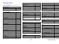 4
4
-
 5
5
-
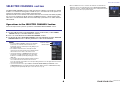 6
6
-
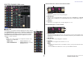 7
7
-
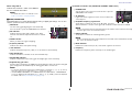 8
8
-
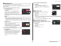 9
9
-
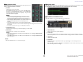 10
10
-
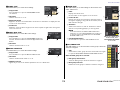 11
11
-
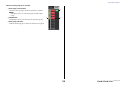 12
12
-
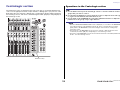 13
13
-
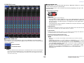 14
14
-
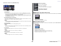 15
15
-
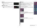 16
16
-
 17
17
-
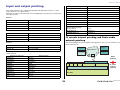 18
18
-
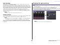 19
19
-
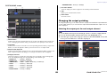 20
20
-
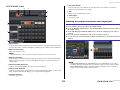 21
21
-
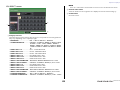 22
22
-
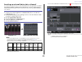 23
23
-
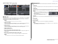 24
24
-
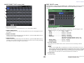 25
25
-
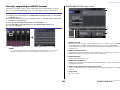 26
26
-
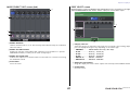 27
27
-
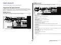 28
28
-
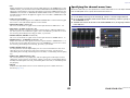 29
29
-
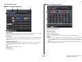 30
30
-
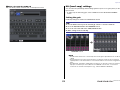 31
31
-
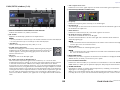 32
32
-
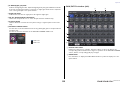 33
33
-
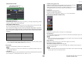 34
34
-
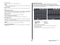 35
35
-
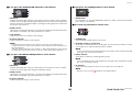 36
36
-
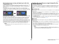 37
37
-
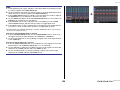 38
38
-
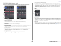 39
39
-
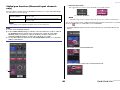 40
40
-
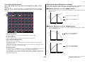 41
41
-
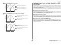 42
42
-
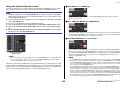 43
43
-
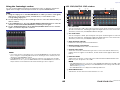 44
44
-
 45
45
-
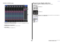 46
46
-
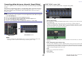 47
47
-
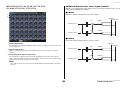 48
48
-
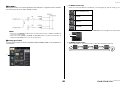 49
49
-
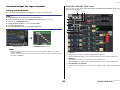 50
50
-
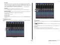 51
51
-
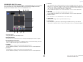 52
52
-
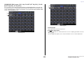 53
53
-
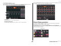 54
54
-
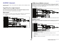 55
55
-
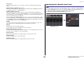 56
56
-
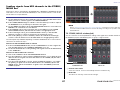 57
57
-
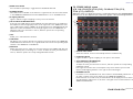 58
58
-
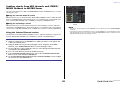 59
59
-
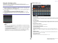 60
60
-
 61
61
-
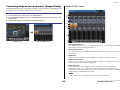 62
62
-
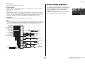 63
63
-
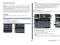 64
64
-
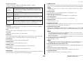 65
65
-
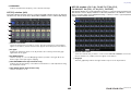 66
66
-
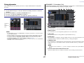 67
67
-
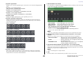 68
68
-
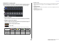 69
69
-
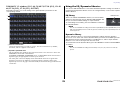 70
70
-
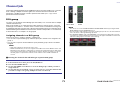 71
71
-
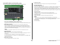 72
72
-
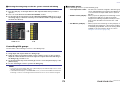 73
73
-
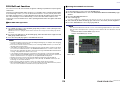 74
74
-
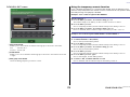 75
75
-
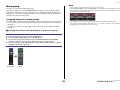 76
76
-
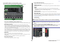 77
77
-
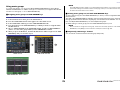 78
78
-
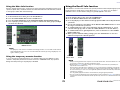 79
79
-
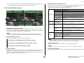 80
80
-
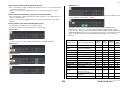 81
81
-
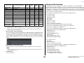 82
82
-
 83
83
-
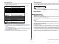 84
84
-
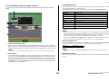 85
85
-
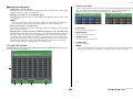 86
86
-
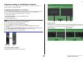 87
87
-
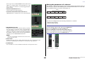 88
88
-
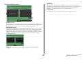 89
89
-
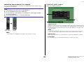 90
90
-
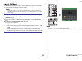 91
91
-
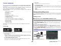 92
92
-
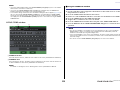 93
93
-
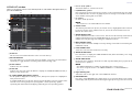 94
94
-
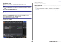 95
95
-
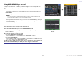 96
96
-
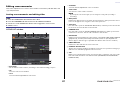 97
97
-
 98
98
-
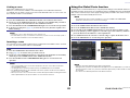 99
99
-
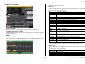 100
100
-
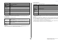 101
101
-
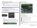 102
102
-
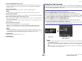 103
103
-
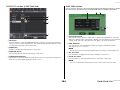 104
104
-
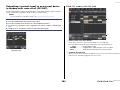 105
105
-
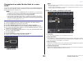 106
106
-
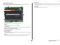 107
107
-
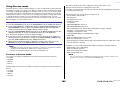 108
108
-
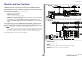 109
109
-
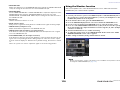 110
110
-
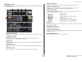 111
111
-
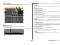 112
112
-
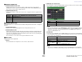 113
113
-
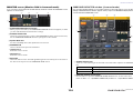 114
114
-
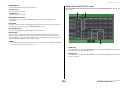 115
115
-
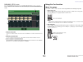 116
116
-
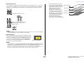 117
117
-
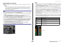 118
118
-
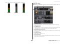 119
119
-
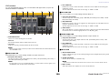 120
120
-
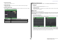 121
121
-
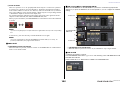 122
122
-
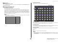 123
123
-
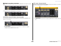 124
124
-
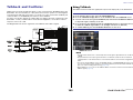 125
125
-
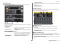 126
126
-
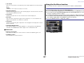 127
127
-
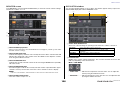 128
128
-
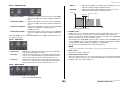 129
129
-
 130
130
-
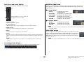 131
131
-
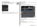 132
132
-
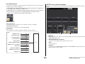 133
133
-
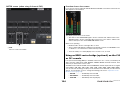 134
134
-
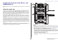 135
135
-
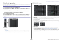 136
136
-
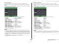 137
137
-
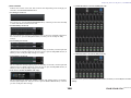 138
138
-
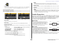 139
139
-
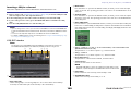 140
140
-
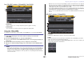 141
141
-
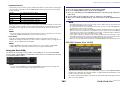 142
142
-
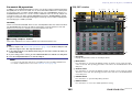 143
143
-
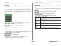 144
144
-
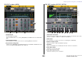 145
145
-
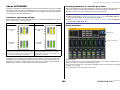 146
146
-
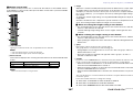 147
147
-
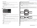 148
148
-
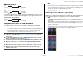 149
149
-
 150
150
-
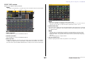 151
151
-
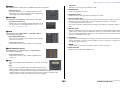 152
152
-
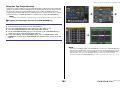 153
153
-
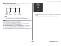 154
154
-
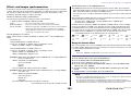 155
155
-
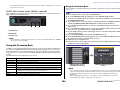 156
156
-
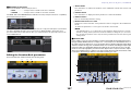 157
157
-
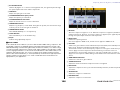 158
158
-
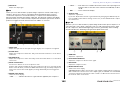 159
159
-
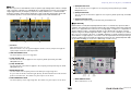 160
160
-
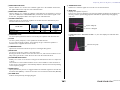 161
161
-
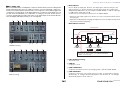 162
162
-
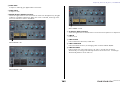 163
163
-
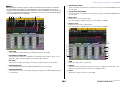 164
164
-
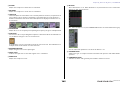 165
165
-
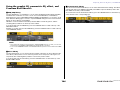 166
166
-
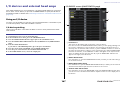 167
167
-
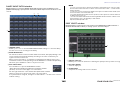 168
168
-
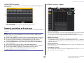 169
169
-
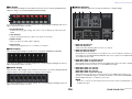 170
170
-
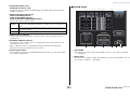 171
171
-
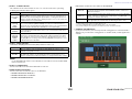 172
172
-
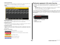 173
173
-
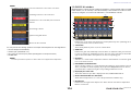 174
174
-
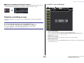 175
175
-
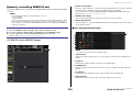 176
176
-
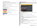 177
177
-
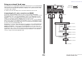 178
178
-
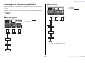 179
179
-
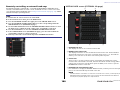 180
180
-
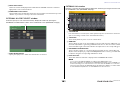 181
181
-
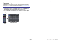 182
182
-
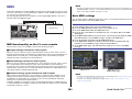 183
183
-
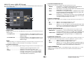 184
184
-
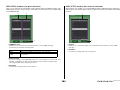 185
185
-
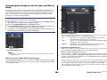 186
186
-
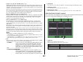 187
187
-
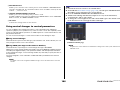 188
188
-
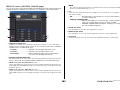 189
189
-
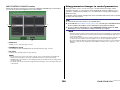 190
190
-
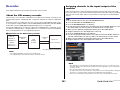 191
191
-
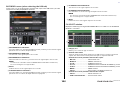 192
192
-
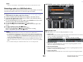 193
193
-
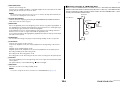 194
194
-
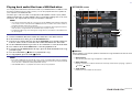 195
195
-
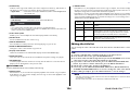 196
196
-
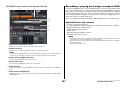 197
197
-
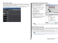 198
198
-
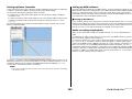 199
199
-
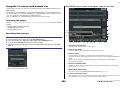 200
200
-
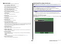 201
201
-
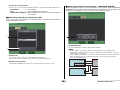 202
202
-
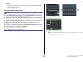 203
203
-
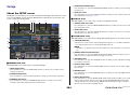 204
204
-
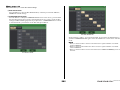 205
205
-
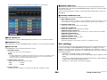 206
206
-
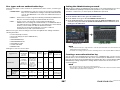 207
207
-
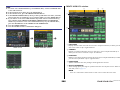 208
208
-
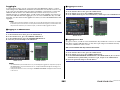 209
209
-
 210
210
-
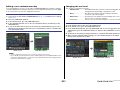 211
211
-
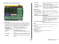 212
212
-
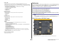 213
213
-
 214
214
-
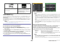 215
215
-
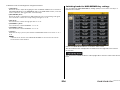 216
216
-
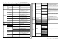 217
217
-
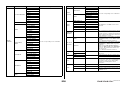 218
218
-
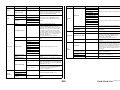 219
219
-
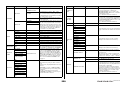 220
220
-
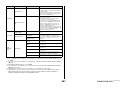 221
221
-
 222
222
-
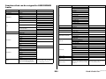 223
223
-
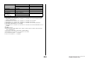 224
224
-
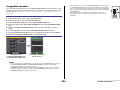 225
225
-
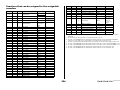 226
226
-
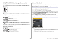 227
227
-
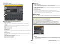 228
228
-
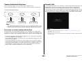 229
229
-
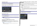 230
230
-
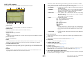 231
231
-
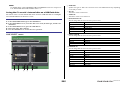 232
232
-
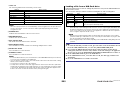 233
233
-
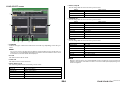 234
234
-
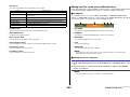 235
235
-
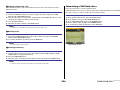 236
236
-
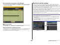 237
237
-
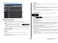 238
238
-
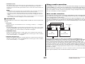 239
239
-
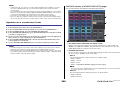 240
240
-
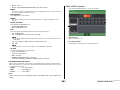 241
241
-
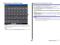 242
242
-
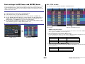 243
243
-
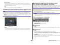 244
244
-
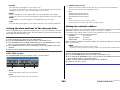 245
245
-
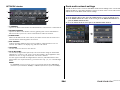 246
246
-
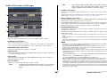 247
247
-
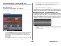 248
248
-
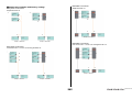 249
249
-
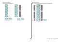 250
250
-
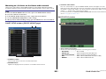 251
251
-
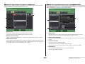 252
252
-
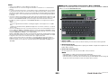 253
253
-
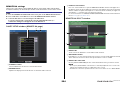 254
254
-
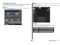 255
255
-
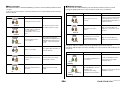 256
256
-
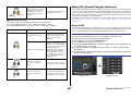 257
257
-
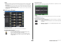 258
258
-
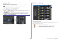 259
259
-
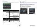 260
260
-
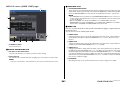 261
261
-
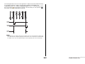 262
262
-
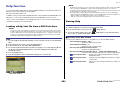 263
263
-
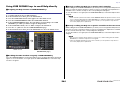 264
264
-
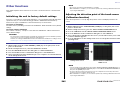 265
265
-
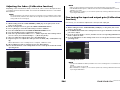 266
266
-
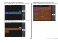 267
267
-
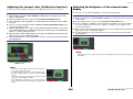 268
268
-
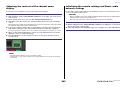 269
269
-
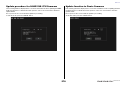 270
270
-
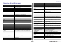 271
271
-
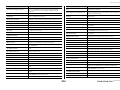 272
272
-
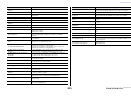 273
273
-
 274
274
-
 275
275
-
 276
276
-
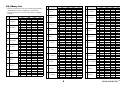 277
277
-
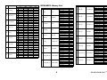 278
278
-
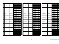 279
279
-
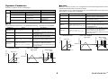 280
280
-
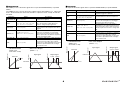 281
281
-
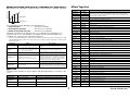 282
282
-
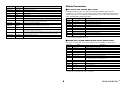 283
283
-
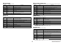 284
284
-
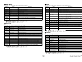 285
285
-
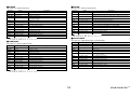 286
286
-
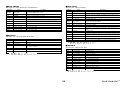 287
287
-
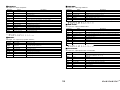 288
288
-
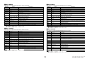 289
289
-
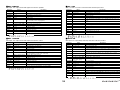 290
290
-
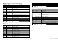 291
291
-
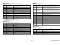 292
292
-
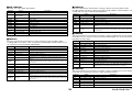 293
293
-
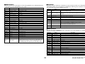 294
294
-
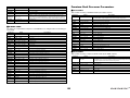 295
295
-
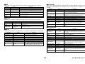 296
296
-
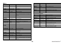 297
297
-
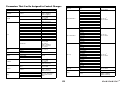 298
298
-
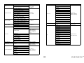 299
299
-
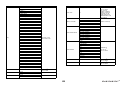 300
300
-
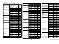 301
301
-
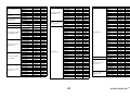 302
302
-
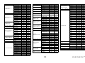 303
303
-
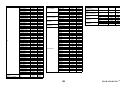 304
304
-
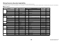 305
305
-
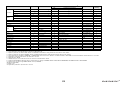 306
306
-
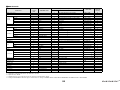 307
307
-
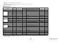 308
308
-
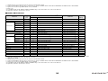 309
309
-
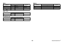 310
310
-
 311
311
-
 312
312
-
 313
313
-
 314
314
-
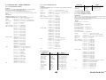 315
315
-
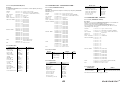 316
316
-
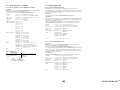 317
317
-
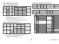 318
318
-
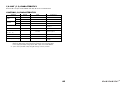 319
319
-
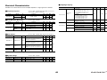 320
320
-
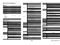 321
321
-
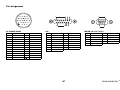 322
322
-
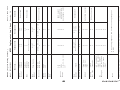 323
323
-
 324
324


Yamaha CL1 Manual de usuario
- Categoría
- Software
- Tipo
- Manual de usuario
en otros idiomas
- français: Yamaha CL1 Manuel utilisateur
- italiano: Yamaha CL1 Manuale utente
- English: Yamaha CL1 User manual
- Deutsch: Yamaha CL1 Benutzerhandbuch
- русский: Yamaha CL1 Руководство пользователя
- Nederlands: Yamaha CL1 Handleiding
- português: Yamaha CL1 Manual do usuário
- dansk: Yamaha CL1 Brugermanual
- polski: Yamaha CL1 Instrukcja obsługi
- čeština: Yamaha CL1 Uživatelský manuál
- svenska: Yamaha CL1 Användarmanual
- Türkçe: Yamaha CL1 Kullanım kılavuzu
- suomi: Yamaha CL1 Ohjekirja
- română: Yamaha CL1 Manual de utilizare
Artículos relacionados
-
Yamaha CL5 Manual de usuario
-
Yamaha V3 Manual de usuario
-
Yamaha QL5 Manual de usuario
-
-
Yamaha QL5 Manual de usuario
-
-
-
-
-