Tripp Lite SRWF5U 5U Wallmount Rack Enclosure El manual del propietario
- Categoría
- Bastidores
- Tipo
- El manual del propietario

Table of Contents
1. Important Safety Instructions 2
2. Overview 2
3. Feature Identification 3
4. Enclosure Installation 4
4.1 Preparation 4
4.2 Unpacking 4
5. Enclosure Configuration 5
5.1 Door Locks 5
5.2 Cable Access & Management 5
5.3 Reversing the Front Door 5
5.4 Mounting Rails 6
5.5 Adjusting Mounting Rail Depth 6
6. Wall Mounting the Enclosure 6
6.1 Mounting 6
7. Equipment Installation 7
8. Optional Patch Panel Installation 7
9. Specifications 7
10. Storage and Service 8
11. Warranty & Product Registration 8
Español 9
5U Low-Profile Wall-Mount
SmartRack
™
Enclosure
Model: SRWF5U
Owner’s Manual
1111 W. 35th Street, Chicago, IL 60609 USA • www.tripplite.com/support
Copyright © 2015 Tripp Lite. All trademarks are the sole property of their respective owners.
PROTECT YOUR INVESTMENT!
Register your product for quicker service and ultimate peace of mind.
You could also win an ISOBAR6ULTRA surge protector—a $50 value!
www.tripplite.com/warranty
15-01-191 93-3126.indb 1 1/23/2015 4:29:41 PM

2
1. Important Safety Instructions
2. Overview
SAVE THESE INSTRUCTIONS
This Manual contains instructions and warnings that must be followed during the installation and operation of the product described in this manual. Failure to
comply may invalidate the warranty and cause property damage or personal injury.
• Keep the enclosure in a controlled indoor environment, away from moisture, temperature extremes, flammable liquids and gasses, conductive
contaminants, dust and direct sunlight.
• Leave adequate space at the front and rear of the enclosure for proper ventilation. Do not block, cover or insert objects into the external ventilation
openings of the enclosure.
• The enclosure is extremely heavy. Use caution when handling the enclosure. Do not attempt to unpack, move or install it unassisted. Use a
mechanical device such as a forklift or pallet jack to move the enclosure in the shipping container.
• Do not place any object on the enclosure, especially containers of liquid, and do not attempt to stack the enclosures.
• Inspect the shipping container and the enclosure for shipping damage. Do not use the enclosure if it is damaged.
• Leave the enclosure in the shipping container until it has been moved as close to the final installation location as possible.
• Install the enclosure in a structurally sound area capable of handling the load, or on a level floor that is able to bear the weight of the enclosure, all
equipment that will be installed in the enclosure and any other enclosures and/or equipment that will be installed nearby.
• Use caution when cutting packing materials. The enclosure could be scratched, causing damage not covered by the warranty.
• Save all packing materials for later use. Repacking and shipping the enclosure without the original packing materials may cause product damage
that will void the warranty.
• Do not reship the enclosure with additional equipment unless the enclosure was shipped with a special shock pallet (“SP1” models only). The
combined weight of the enclosure and installed equipment must not exceed the load capacity of the pallet. Tripp Lite is not responsible for any
damage that occurs during reshipment.
• Use of this equipment in life support applications where failure of this equipment can reasonably be expected to cause the failure of the life support
equipment or to significantly affect its safety or effectiveness is not recommended. Do not use this equipment in the presence of a flammable
anesthetic mixture with air, oxygen or nitrous oxide.
The SRWF5U Low-Profile Wall-Mount SmartRack Enclosure provides convenient and secure vertical mounting for all standard 19-inch rackmount
equipment, regardless of vendor, and ships fully assembled for quick and easy deployment.
15-01-191 93-3126.indb 2 1/23/2015 4:29:41 PM

3
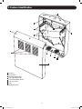
3. Feature Identification
1
Front Door
2
Top Panel Door
3
Horizontal Mounting Rails
4
Vertical Mounting Bracket
5
Patch Panel Mounting Bracket
6
Cable Access Holes
7
Vents
8
Wall-Mounting Slots
2
7
3
5
5
6
6
6
7
7
4
1
8
8
15-01-191 93-3126.indb 3 1/23/2015 4:29:41 PM

4
4. Enclosure Installation
4.1 Preparation
4.2 Unpacking
Caution! Read All Instructions and Warnings Before Installation!
Warning: Rack enclosures can be extremely heavy. Do not attempt to unpack, move or install the enclosure without assistance. Use
extreme caution when handling the enclosure and be sure to follow all handling and installation instructions. Do not attempt to install
equipment without first stabilizing the enclosure.
The enclosure must be installed in a structually sound area that is able to bear the weight of the enclosure, all the equipment that will be installed in the
enclosure and any other enclosures and/or equipment that will be installed nearby. Before unpacking the enclosure, you should transport the shipping
container closer to the final installation location to minimize the distance you will need to move the unit after the protective packaging has been removed.
If you plan to store the enclosure for an extended period before installation, follow the instructions in the Storage and Service section.
You need several tools:
• Level
• Phillips-head Screwdriver
• Appropriate tools for wall mounting
You also need the following hardware:
• Appropriate hardware for wall mounting (not included)
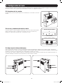
Use at least two people to unpack the enclosure.
Never extend more than one component from the enclosure at a time.
Warning: Never attempt to lift or install without adequate help.
Do not try lifting the enclosure alone.
1
Move shipping pallet to a firm, level surface.
2
Open box and remove the four foam cormer protectors. Save all packing materials for later use unless you are certain they will not be required.
Packing materials are recyclable.
3
With one person on each side, carefully lift the enclosure out of the box and place on a firm, level surface.
4
Examine the enclosure for any damage or loose parts. Confirm all parts are present. If anything is missing or damaged, contact Tripp Lite for
assistance. Do not attempt to use the enclosure if it has been damaged.
15-01-191 93-3126.indb 4 1/23/2015 4:29:42 PM

5
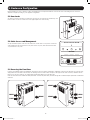
5. Enclosure Configuration
5.1 Door Locks
5.2 Cable Access and Management
The front door and the top panel door both have locks that are accessible by the included keys. The
front door latch can also be locked with a user-supplied padlock for extra security.
The top and bottom panels of the enclosure both have circular cable access ports for convenient
cable management. The top has three 1.75” ports and two 1” ports, while the bottom has three
1” ports and two 1.75” ports.
Before installation, be sure to plan the location and arrangement of components within the enclosure. Be sure all mounting rails are reversed or
adjusted for depth, depending on your equipment configuration.
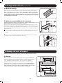
5.3 Reversing the Front Door
In order to accommodate various rack installations, the front door can be reversed by switching the configuration of its latch, lock and hinges. To reverse the door,
simply remove the screws that secure the latch, lock and hinges to the enclosure. Move each piece to the opposite side of the enclosure, so that there are two
hinges on one side (one at the top, one at the bottom) and the latch and the lock on the other side.
Note: The unused screw holes are filled with rubber placeholders. To remove the placeholders, push them through with a screwdriver. Keep the placeholders to refill unused
screw holes.
HINGE
HINGE
HINGE
HINGE
LATCH
LATCH
LOCK
LOCK
HINGE
HINGE
HINGE
HINGE
LATCH
LATCH
LOCK
LOCK
TOP VIEW
BOTTOM VIEW
15-01-191 93-3126.indb 5 1/23/2015 4:29:42 PM

6
5. Enclosure Configuration
(
continued
)
6. Wall Mounting the Enclosure
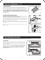
5.4 Mounting Rails
6.1 Mounting
5.5 Adjusting Mounting Rail Depth
The enclosure comes with reversible horizontal mounting rails that have threaded holes for
mounting rack equipment. The holes on the top of the rail are threaded for M6 hardware, while the
holes on the bottom are threaded for 12-24. To install equipment, use the included M6 or 12-24
hardware to secure equipment to the rails. (See the following page for equipment installation
instructions.) Warning: Be sure to have the enclosure securely mounted to the wall, or in its
final position on the floor before mounting any equipment inside. Also be sure to have all
the right adjustments on your rails before mounting equipment. (See below for Adjusting
Mounting Rail Depth.)
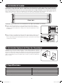
There are 20 keyhole cutouts on the back door of the enclosure arranged in 4 sets of 5.
Each keyhole can accommodate an M10 or 3/8” bolt. The holes are on 16" centers, with
the holes in each set 2” apart from center to center. Holes are then 15” apart vertically,
as shown in the diagram.
Using a level, measure to position your mounting areas precisely. Use appropriate fasteners
(not included) to secure the enclosure to the wall. Warning: The area you plan to mount
the enclosure to must be able to withstand the weight of the enclosure and all
mounted equipment. For the weight of the enclosure and its capacity, see the
specifications on page 8.
Warning: Do not attempt to adjust rails while equipment is installed in the enclosure. Do
not attempt to use rails without screws installed. (2 per rail.)
The two horizontal mounting rails are pre-installed to accommodate equipment with a mounting
depth of 20 inches (508 mm). Do not adjust the mounting rails unless your equipment requires a
different mounting depth. The rails can be adjusted in 1-inch increments for mounting depths
between 17 inches (432 mm) and 20 inches (508 mm).
1
Each rail is connected to the enclosure with 2 screws: 1 at the front of the enclosure and one
at the rear. Using a Philips-head screwdriver, remove the screws that fasten the rails to the
enclosure.
2
Slide the mounting rails vertically to the desired depth and reattach them using the screws you
removed in Step 1.
Warning: Do not attempt to mount the enclosure to the wall with equipment mounted in the enclosure.
15”
16”
16”
12”
8”
20”
24”
16”
16”
16”
16”
1
2
M6
12-24
15-01-191 93-3126.indb 6 1/23/2015 4:29:43 PM

7
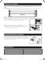
7. Equipment Installation
8. Optional Patch Panel Installation
The SRWF5U comes with an integral, slide-out mounting bracket at the top of the enclosure. It can
be used to secure a patch panel to the enclosure, and it partially slides out for easier cabling
access. To install a patch panel on the patch panel mounting bracket, use the included mounting
screws and washers to secure your equipment to the rack rail. Place the washers between the
screws and the patch panel mounting bracket.
Warning: Do not install equipment until you have stabilized the enclosure. If using sliding equipment rails, be careful when extending the
rails. Do not extend more than one set of sliding equipment rails at one time. Avoid extending sliding equipment rails near the top of the
enclosure.
Note: The threaded holes in the middle of each rack unit are numbered. A single rack unit includes the space occupied by the numbered hole and the holes
directly above and below.
WARNING: Follow the instructions in your equipment documentation to ensure proper installation of your equipment.
1
Locate the numbered openings in the mounting rails where you plan to install your equipment.
Lower your equipment into the enclosure and set it down on the mounting rails, lining up the
mounting holes on the equipment with the mounting rail’s mounting holes.
2
Use the included mounting screws and washers to secure your equipment to the rack rail. Place
the washers between the screws and the equipment mounting brackets.
Note: Your equipment may also include mounting hardware. Read the mounting instructions that
came with your equipment before installing your equipment.
9. Specifications
Model SRWF5U
Dimensions (H x W x D) 28.8 x 25.6 x 9.7” (732 x 651 x 247 mm)
Unit Weight 45 lb (20.4 kg)
Load Capacity* 150 lb (68.1 kg)
Mounting Depth (Adjustable) 17” to 20” (432 to 508 mm)
* Full wall-mount load capacity requires a mounting surface capable of bearing the full load.
1
2
3
4
5
1
2
3
4
5
1
2
1
2
3
4
5
1
2
3
4
5
3
3
1 Rack Unit
15-01-191 93-3126.indb 7 1/23/2015 4:29:44 PM

8
5-Year Limited Warranty
Seller warrants this product, if used in accordance with all applicable instructions, to be free from original defects in material and workmanship for a period of 5
years from the date of initial purchase. If the product should prove defective in material or workmanship within that period, Seller will repair or replace the
product, at its sole discretion.
THIS WARRANTY DOES NOT APPLY TO NORMAL WEAR OR TO DAMAGE RESULTING FROM ACCIDENT, MISUSE, ABUSE OR NEGLECT. SELLER MAKES NO
EXPRESS WARRANTIES OTHER THAN THE WARRANTY EXPRESSLY SET FORTH HEREIN. EXCEPT TO THE EXTENT PROHIBITED BY APPLICABLE LAW, ALL IMPLIED
WARRANTIES, INCLUDING ALL WARRANTIES OF MERCHANTABILITY OR FITNESS, ARE LIMITED IN DURATION TO THE WARRANTY PERIOD SET FORTH ABOVE;
AND THIS WARRANTY EXPRESSLY EXCLUDES ALL INCIDENTAL AND CONSEQUENTIAL DAMAGES. (Some states do not allow limitations on how long an implied
warranty lasts, and some states do not allow the exclusion or limitation of incidental or consequential damages, so the above limitations or exclusions may not
apply to you. This warranty gives you specific legal rights, and you may have other rights which vary from jurisdiction to jurisdiction).
WARNING: The individual user should take care to determine prior to use whether this device is suitable, adequate or safe for the use intended. Since individual
applications are subject to great variation, the manufacturer makes no representation or warranty as to the suitability or fitness of these devices for any specific
application.
Product Registration
Visit www.tripplite.com/warranty today to register your new Tripp Lite product. You’ll be automatically entered into a drawing for a chance to win a FREE Tripp Lite product!*
* No purchase necessary. Void where prohibited. Some restrictions apply. See website for details.
Tripp Lite has a policy of continuous improvement. Specifications are subject to change without notice.
10. Storage and Service
11. Warranty and Product Registration
Storage
The enclosure should be stored in a controlled indoor environment, away from moisture, temperature extremes, flammable liquids and gasses,
conductive contaminants, dust and direct sunlight. Store the enclosure in its original shipping container if possible.
Service
Your Tripp Lite product is covered by the warranty described in this manual. A variety of Extended Warranty and On-Site Service Programs are also
available from Tripp Lite. For more information on service, visit www.tripplite.com/support. Before returning your product for service, follow these steps:
1. Review the installation and operation procedures in this manual to insure that the service problem does not originate from a misreading of the
instructions.
2. If the problem continues, do not contact or return the product to the dealer. Instead, visit www.tripplite.com/support.
3. If the problem requires service, visit www.tripplite.com/support and click the Product Returns link. From here you can request a Returned Material
Authorization (RMA) number, which is required for service. This simple on-line form will ask for your unit’s model and serial numbers, along with
other general purchaser information. The RMA number, along with shipping instructions will be emailed to you. Any damages (direct, indirect, special
or consequential) to the product incurred during shipment to Tripp Lite or an authorized Tripp Lite service center is not covered under warranty.
Products shipped to Tripp Lite or an authorized Tripp Lite service center must have transportation charges prepaid. Mark the RMA number on the
outside of the package. If the product is within its warranty period, enclose a copy of your sales receipt. Return the product for service using an
insured carrier to the address given to you when you request the RMA.
1111 W. 35th Street, Chicago, IL 60609 USA • www.tripplite.com/support
15-01-191 93-3126.indb 8 1/23/2015 4:29:44 PM

9
Índice
1. Instrucciones de seguridad
importantes 10
2. Descripción general 10
3. Identificación de características 11
4. Enclosure Installation 12
4.1 Preparación 12
4.2 Desembalaje 12
5. Configuración del rack 13
5.1 Cerraduras de las puertas 13
5.2 Acceso y administración 13
de los cables
5.3 Inversión del rack 13
5.4 Rieles de montaje 14
5.5 Ajuste de la profundidad 14
del riel de montaje
6. Montaje del rack a la pared 14
6.1 Montaje 14
7. Instalación del equipo 15
8. Instalación Opcional del Panel
de Conexiones 15
9. Especificaciones 15
10. Almacenamiento y mantenimiento 16
11. Garantía 16
English 1
Gabinete SmartRack™ de Bajo
Perfil Para Instalación en la Pared
Modelo: SRWF5U
Manual del propietario
1111 W. 35th Street, Chicago, IL 60609 USA • www.tripplite.com/support
Copyright © 2015 Tripp Lite. Todas las otras marcas registradas son propiedad de sus respectivos dueños.
15-01-191 93-3126.indb 9 1/23/2015 4:29:45 PM

10
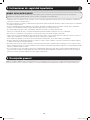
1. Instrucciones de seguridad importantes
2. Descripción general
GUARDE ESTAS INSTRUCCIONES
Este manual contiene instrucciones y advertencias que deben seguirse durante la instalación y operación del producto descrito en este manual. El
incumplimiento invalidará la garantía, pudiendo causar serios daños a la propiedad y/o lesiones personales.
• Mantenga el rack en un ambiente interior controlado, lejos de la humedad, temperaturas extremas, líquidos y gases inflamables, contaminantes
conductores, el polvo y la luz directa del sol.
• Deje espacio suficiente en el frente y la parte trasera del rack para una ventilación adecuada. No bloquee, cubra ni inserte objetos en las aberturas
de ventilación externa del rack.
• El rack es extremadamente pesado. Manipúlelo con precaución. No intente desembalarlo, moverlo ni instalarlo sin ayuda. Utilice un dispositivo
mecánico como una horquilla elevadora o un gato para pálets para moverlo en el contenedor de envío.
• No coloque ningún objeto sobre el rack, especialmente contenedores de líquido, y no intente apilar los racks.
• Inspeccione el contenedor de envío y el rack para detectar daños producidos durante el transporte. No lo use si está dañado.
• Deje el rack en el contenedor de envío hasta que se lo haya movido lo más cerca posible del lugar de instalación.
• Instale el rack en un área estructuralmente sana, capaz de soportar la carga, o con piso nivelado capaz de soportar el peso del rack, de todos los
equipos que se instalarán en el rack y de cualquier otro rack y/o equipo que se instalarán cerca.
• Corte el material de embalaje con precaución. El rack podría rayarse causando daños que no están cubiertos por la garantía.
• Guarde los materiales de embalaje para utilizarlos en el futuro. Si el rack se vuelve a embalar y a enviar sin los materiales de embalaje originales,
se pueden causar daños que anularán la garantía.
• No vuelva a enviar el rack con equipos adicionales, a menos que haya sido enviado con un pálet especial contra golpes (sólo los modelos “SP1”).
El peso combinado del rack y de los equipos instalados no debe exceder la capacidad de carga del pálet. Tripp Lite no se responsabiliza por ningún
daño que se produzca durante el reenvío.
• No se recomienda el uso de este equipo en aplicaciones de mantenimiento artificial de la vida, donde se puede esperar razonablemente que su
falla cause la falla del equipo de mantenimiento de la vida o que afecte de manera importante su seguridad o eficiencia. No use este equipo en
presencia de mezclas anestésicas inflamables con aire, oxígeno u óxido nitroso.
El Gabinete SmartRack SRWF5U de Bajo Perfil para instalación en la Pared proporciona una conveniente y segura instalación vertical para todos los
equipos para instalar en rack, sin importar el vendedor, y se embarca completamente ensamblado para una ubicación e instalación rápida y fácil.
15-01-191 93-3126.indb 10 1/23/2015 4:29:45 PM

11
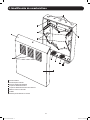
3. Identificación de características
1
Puerta delantera
2
Puerta Superior del Panel
3
Rieles de Instalación Horizontal
4
Soporte de Instalación Vertical
5
Soporte de Instalación del Panel de Conexiones
6
Orificios de Acceso del Cable
7
Ventilas
8
Ranuras para Instalación en la Pared
2
7
3
5
5
6
6
6
7
7
4
1
8
8
15-01-191 93-3126.indb 11 1/23/2015 4:29:46 PM

12
4. Instalación del rack
4.1 Preparación
4.2 Desembalaje
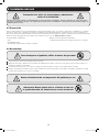
Precaución. Lea todas las instrucciones y advertencias
antes de la instalación.
Advertencia: Los racks pueden ser extremadamente pesados. No intente desembalarlo, moverlo ni instalarlo sin ayuda. Use máxima
precaución al manipularlo y asegúrese de seguir todas las instrucciones de manipulación e instalación. No intente instalar equipos sin
estabilizar primero el rack.
El rack se debe instalar en una zona estructuralmente sana que pueda soportar su peso, el de todos los equipos que se instalarán en él y cualquier
otro rack y/o equipos que se instalarán cerca. Antes de desembalar el rack, debería transportar el contenedor de envío lo más cerca posible de la
ubicación de instalación final para minimizar la distancia que necesitará para moverlo después de quitarle el embalaje protector. Si planea almacenarlo
durante un período prolongado antes de instalarlo, siga las instrucciones de la sección Almacenamiento y servicio.
Necesitará algunas herramientas:
• Nivel
• Destornillador Philips
• Herramientas adecuadas para el montaje en la pared
También necesita las siguientes herramientas:
• Herramientas adecuadas para el montaje en pared (no se incluyen)
Para desempacar el gabinete, utilice al menos dos personas
Nunca extienda más de un componente del gabinete por vez.
Advertencia: Nunca intente elevar o instalar el rack sin
la ayuda adecuada. No intente elevar el rack usted solo.
1
Mueva del pálet de envío hacia una superficie firme y nivelada.
2
Extraiga los protectores y guarde todos los materiales de embalaje para uso futuro, a menos que esté seguro de que no serán necesarios. Los
materiales de embalaje son reciclables.
3
Con una persona de cada lado, eleve el rack con cuidado hacia fuera del pálet y colóquelo en una superficie firme y nivelada.
4
Examine el rack para detectar daños o partes sueltas. Confirme que estén todas las partes. Si algo falta o está dañado, comuníquese con Tripp
Lite para obtener ayuda. No use el rack si está dañado.
15-01-191 93-3126.indb 12 1/23/2015 4:29:46 PM

13
5. Configuración del rack
5.1 Cerraduras de las puertas
5.2 Acceso y administración de los cables
La puerta frontal y la puerta del panel superior tienen cerraduras que son accesibles con las llaves
incluidas.
Los paneles superior e inferior del gabinete, tienen puertos de acceso de cable circulares para un
manejo conveniente del cable. El superior tiene tres puertos de 1.75” y dos puertos de 1”,
mientras que el inferior tiene tres puertos de 1” y dos puertos de 1.75”.
Antes de la instalación, asegúrese de planificar la ubicación y distribución de los componentes dentro del gabinete. Asegúrese de que todos los rieles
de instalación estén al revés o ajustados según la profundidad, de acuerdo a la configuración del equipo.
5.3 Cómo invertir la Puerta Delantera
A fin de acomodar varias instalaciones de racks, la puerta delantera se puede invertir alternando la configuración de sus pestillos y bisagras. Para invertir la
puerta, simplemente retire los tornillos que aseguran las bisagras y los pestillos al gabinete. Mueva cada pieza al lado opuesto del gabinete, de manera que haya
dos bisagras en un lado (una en la parte superior, una en la parte inferior) y un pestillo en el otro lado.
Nota: Los orificios de los tornillos no utilizados se rellenan con los marcadores de posición de hule. Para quitar los marcadores de posición, empújelos hacia adentro con
un desarmador. Mantenga los marcadores de posición para rellenar los orificios de tornillos no utilizados.
BISAGRA
BISAGRA
BISAGRA
BISAGRA
PESTILLO
PESTILLO
CERRADURA
CERRADURA
BISAGRA
BISAGRA
BISAGRA
BISAGRA
PESTILLO
PESTILLO
CERRADURA
CERRADURA
VISTA SUPERIOR
VISTA INFERIOR
15-01-191 93-3126.indb 13 1/23/2015 4:29:46 PM

14
5. Configuración del rack
(continuación)
6. Montaje del rack a la pared
5.4 Rieles de montaje
6.1 Montaje
5.5 Ajuste de la profundidad del riel de montaje
El gabinete viene con rieles de instalación horizontales que tienen orificios roscados para instalar el
equipo en el rack. Para instalar el equipo, use el los tornillos M6 incluidos. (Vea la siguiente
página con las instrucciones para instalar el equipo.) Advertencia: Asegúrese de que el rack
quede montado firmemente a la pared, o en su posición final en el piso antes de montar
cualquier equipo en el interior. Asegúrese también de realizar todos los ajustes adecuados
de rieles antes de montar los equipos. (Consulte la sección siguiente para ver el Ajuste de
la profundidad del riel de montaje).
Existen 20 perforaciones en la parte trasera del rack. Cada orificio está adaptado para
insertar un perno M10 o de 3/8". Los orificios están en centros de 16 pulgadas, con los
orificios en cada conjunto de 2 pulgadas de distancia de centro a centro. Los orificios
son de 15 pulgadas de distancia en vertical, como se muestra en el diagrama.
Utilizando un nivel, mida la posición de las áreas de montaje en forma precisa. Utilice
pasadores adecuados (no incluidos) para asegurar el rack a la pared. Advertencia: Las
herramientas que planea utilizar y el área en donde planea montar el rack deben
poder soportar el peso del rack y de todos los equipos montados. Para ver el peso
del rack y su capacidad, consulte las Especificaciones en la página 16.
Advertencia: No intente ajustar los rieles mientras los equipos están instalados en el rack.
No intente utilizar rieles sin tornillos instalados. (2 por riel).
Los dos rieles de instalación horizontal están preinstalados para acomodar los equipos con una
profundidad de instalación de 20 pulgadas (508 mm). No ajuste los rieles de instalación a menos
que los equipos requieran una profundidad de instalación distinta. Los rieles se pueden ajustar en
incrementos de 1 pulgada para profundidades de instalación de entre 17 pulgadas (432 mm) y 20
pulgadas (508 mm).
1
Cada riel se conecta al gabinete con dos tornillos: 1 al frente del gabinete y otro por la parte
trasera. Utilizando un desatornillador Phillips, extraiga los tornillos que ajustan los rieles al
gabinete.
2
Deslice los rieles de instalación verticalmente hasta la profundidad deseada y vuelva a unirlos
mediante los tornillos que extrajo anteriormente en el Paso 1.
Advertencia: No intente montar el rack en la pared con equipos montados en el rack.
15”
16”
16”
12”
8”
20”
24”
16”
16”
16”
16”
1
2
M6
12-24
15-01-191 93-3126.indb 14 1/23/2015 4:29:47 PM

15
7. Instalación del equipo
8. Instalación Opcional del Panel de Conexiones
El SRWF5U viene con un soporte integral, deslizable en la parte superior del gabinete. Se puede
utilizar para asegurar un panel de conexión al gabinete, y se desliza parcialmente hacia afuera para
tener un acceso más fácil al cableado. Para instalar un panel de conexión al soporte de instalación
del panel de conexión, utilice los tornillos de instalación y las arandelas incluidas para asegurar su
equipo al riel del gabinete. Coloque las arandelas entre los tornillos y el soporte de instalación del
panel de conexión.
Advertencia: No instale equipos hasta que haya estabilizado el rack. Instale primero los equipos más pesados en la parte inferior del
rack. Instálelos de abajo hacia arriba, nunca en sentido contrario. Si usa rieles para equipos deslizantes, tenga cuidado al extender los
rieles. No extienda más de un juego de rieles por vez. Evite extender rieles de equipos deslizantes cerca de la parte superior del rack.
Nota: Los orificios cuadrados en el centro de cada unidad del rack están numerados y también incluyen una pequeña muesca para identificarlos. Una sola
unidad de rack incluye el espacio ocupado por el orificio numerado y los orificios ubicados directamente encima y debajo.
ADVERTENCIA: Siga las instrucciones de la documentación de sus equipos para instalarlos correctamente.
1
Ubique las aberturas numeradas en los rieles de instalación en donde planea instalar los
equipos. Baje su equipo hacia dentro del gabinete y ajústelo sobre los rieles de instalación,
alineando los orificios de instalación en el equipo, con los orificios de instalación de los rieles
de instalación.
2
Utilice los tornillos y las arandelas de instalación incluidos para asegurar su equipo al riel del
gabinete. Coloque las arandelas entre los tornillos y los soportes de instalación del equipo.
Nota: Su equipo también puede incluir herramientas de montaje. Lea las instrucciones de montaje de
su equipo antes de instalarlo.
9. Especificaciones
Modelo SRWF5U
Dimensiones (A x A x P) 28.8 x 25.6 x 9.7 pulg. (732 x 650 x 246 mm)
Peso de la unidad 45 libras (20.4 kg)
Capacidad de carga* 150 libras (68.0 kg)
Profundidad de montaje (ajustable) 17” a 20” (432 a 508 mm)
* La capacidad de carga total para montar en pared requiere una superficie de montaje capaz de soportar toda la carga.
1
2
3
4
5
1
2
3
4
5
1
2
1
2
3
4
5
1
2
3
4
5
3
3
1 Rack Unit
15-01-191 93-3126.indb 15 1/23/2015 4:29:47 PM

16
15-01-191 • 933126-RevB
Garantía limitada por 5 años
El vendedor garantiza que este producto no tiene defectos originales de materiales ni de mano de obra por un período de cinco años a partir de la fecha
original de compra, si se utiliza de acuerdo con todas las instrucciones correspondientes. En caso de demostrarse dentro de ese período que el producto tiene
defectos de materiales o de mano de obra, el vendedor lo reparará o reemplazará a su exclusiva discreción.
ESTA GARANTÍA NO CUBRE EL DESGASTE NORMAL NI LOS DAÑOS CAUSADOS POR ACCIDENTES, MAL USO, ABUSO O NEGLIGENCIA. EL VENDEDOR NO
OFRECE NINGUNA GARANTÍA EXPRESA QUE NO SEA LA ESTABLECIDA EXPRESAMENTE EN EL PRESENTE DOCUMENTO. EXCEPTO EN LA MEDIDA EN QUE LO
PROHÍBAN LAS LEYES APLICABLES, LA DURACIÓN DE TODAS LAS GARANTÍAS IMPLÍCITAS, INCLUIDAS LAS DE COMERCIABILIDAD O APTITUD, SE LIMITA AL
PERÍODO DE GARANTÍA ANTES MENCIONADO Y ESTA GARANTÍA EXCLUYE EXPRESAMENTE TODOS LOS DAÑOS INCIDENTALES E INDIRECTOS. (Algunos Estados
no permiten las limitaciones a la duración de una garantía implícita y otros Estados no permiten la exclusión o limitación de los daños incidentales o indirectos,
de modo que las limitaciones o exclusiones antes mencionadas pueden no corresponder en su caso. Esta garantía le otorga derechos legales específicos y
usted puede tener otros derechos que varían de una jurisdicción a otra).
ADVERTENCIA: Antes de usar este dispositivo, cada usuario debe ocuparse de determinar si es apto, adecuado o seguro para el uso que pretende darle. Dado
que las aplicaciones individuales están sujetas a diversas variaciones, el fabricante no representa ni garantiza la idoneidad o condición de estos dispositivos
para cualquier aplicación específica.
Tripp Lite tiene la política de mejora continua. Las especificaciones están sujetas a cambios sin notificación previa.
10. Almacenamiento y servicio
11. Garantía
Almacenamiento
El rack debe almacenarse en un ambiente interior controlado, lejos de la humedad, temperaturas extremas, líquidos y gases inflamables,
contaminantes conductores, polvo y luz solar directa. Si es posible, almacénelo en su contenedor de envío original.
Mantenimiento
Su producto Tripp Lite está cubierto por la garantía descrita en este manual. Tripp Lite también pone a su disposición una variedad de Garantías
extendidas y Programas de servicio técnico en el sitio. Si desea más información sobre el servicio técnico, visite www.tripplite.com/support. Antes de
devolver su producto para servicio técnico, siga estos pasos:
1. Revise la instalación y los procedimientos de operación que se encuentran en este manual para asegurarse de que el problema de servicio no se
debe a una mala lectura de las instrucciones.
2. Si el problema persiste, no se comunique ni devuelva el producto al mayorista. En cambio, visite www.tripplite.com/support.
3. Si el problema exige servicio técnico, visite www.tripplite.com/support y haga clic en el enlace Devoluciones de productos. Desde aquí puede
solicitar un número de Autorización de Material Devuelto (RMA), que se necesita para el servicio técnico. En este sencillo formulario en línea se le
solicitarán los números de serie y modelo de la unidad, junto con otra información general del comprador. El número RMA y las instrucciones para
el envío se le enviarán por correo electrónico. La presente garantía no cubre ningún daño (directo, indirecto, especial o consecuencial) del producto
que ocurra durante el envío a Tripp Lite o a un centro de servicio técnico de Tripp Lite autorizado. Los productos enviados a Tripp Lite o a un centro
de servicio técnico de Tripp Lite autorizado deben tener prepagos los cargos de transporte. Escriba el número RMA en el exterior del embalaje. Si el
producto se encuentra dentro del período de garantía, adjunte una copia de su recibo de venta. Envíe el producto para servicio técnico mediante un
transportador asegurado a la dirección que se le proporcionó cuando solicitó el número RMA.
1111 W. 35th Street, Chicago, IL 60609 USA • www.tripplite.com/support
15-01-191 93-3126.indb 16 1/23/2015 4:29:48 PM
-
 1
1
-
 2
2
-
 3
3
-
 4
4
-
 5
5
-
 6
6
-
 7
7
-
 8
8
-
 9
9
-
 10
10
-
 11
11
-
 12
12
-
 13
13
-
 14
14
-
 15
15
-
 16
16


Tripp Lite SRWF5U 5U Wallmount Rack Enclosure El manual del propietario
- Categoría
- Bastidores
- Tipo
- El manual del propietario
en otros idiomas
Artículos relacionados
-
Tripp Lite SRWF5U36 El manual del propietario
-
Tripp Lite SR12UB El manual del propietario
-
Tripp Lite 24U SmartRack® Enclosure El manual del propietario
-
-
-
-
Tripp Lite SRW12UHD & SRW18UHD Wall-Mounted SmartRack Enclosure El manual del propietario
-
Tripp Lite SR18UB El manual del propietario
-
-