Ply Gem Aluminum Series Guía de instalación
- Tipo
- Guía de instalación

2
2
3
1
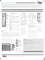
Flashing
(recommended)
Sealant
Fastener
Sheathing
Nail Fin
Penetration
Depth*
Framing
Member
Shim
*Consult local building codes to verify that
sheathing is considered a framing member.
*Consulte los códigos de construcción
locales para verificar que el revestimiento se
considere parte del marco.
NOTE: Mulled units may have additional instructions.
See Ply Gem Windows website for additional instructions that may apply to mulled units.
NOTA: Es posible que las unidades soldadas incluyan instrucciones adicionales. Consulte el sitio web de
Ply Gem Windows para conocer las instrucciones adicionales que pueden aplicarse a las unidades soldadas.
SPACING
ESPACIO ENTRE SUJETADORES
MAX DISTANCE FROM WINDOW CORNERS
DISTANCIA MÁX. DESDE LOS EXTREMOS DE LA VENTANA
BLDG FRAMING PENETRATION
PENETRACIÓN EN LA ESTRUCTURA
MIN. CORROSION-RESISTANT NAIL SIZE
TAMAÑO MÍN. DEL CLAVO RESISTENTE A LA CORROSIÓN
BLDG FRAMING SCREW PENETRATION
PENETRACIÓN DE TORNILLOS EN LA ESTRUCTURA
MIN. CORROSION-RESISTANT SCREW SIZE
TAMAÑO MÍN. DEL TORNILLO RESISTENTE A LA CORROSIÓN
8” spacing or every other hole
8 in de espacio o un orificio de por medio
4” or nearest hole
4 in o el orificio más cercano
1-2" min. (see instructions with window)
2 in mín. (ver instrucciones con ventana)
10 gauge with 3/8” min. head diameter
Calibre 10 con cabeza de 3/8 in de diámetro mín.
1” min. (local code may dictate)
1 in mín. (puede indicarse en el código local)
#8 or larger modified truss head
#8 o superior, cabeza segmentada modificada
STEP 2:
Weather Resistant Barrier, (WRB) Wall Preparation
(RECOMMENDED)
At the Rough Opening (RO)
• Ensure that the weather resistant barrier (WRB) is properly and
securely fastened to the exterior wall surface and is free of wrinkles,
cuts and tears with adequate overlaps as described by the WRB
manufacturer.
• Following the WRB manufacturer’s instructions, begin cutting out the
RO as instructed.
• Cut and remove any excess material as necessary or directed by the
manufacturer.
• Cut two 45-degree slits as described, (based on the width of the
flashing products used), from the top corners of the rough opening at
the header, to create a flap above the rough opening. Fold it up and
temporarily secure this flap over the opening as shown in the image.
PASO 2:
Preparación de la pared para la barrera resistente a la intemperie (RECOMENDADO)
En la abertura sin terminación
• Asegúrese de que la barrera resistente a la intemperie (WRB) esté sujetada a la superficie
de la pared exterior correctamente y en forma segura, no tenga pliegues, cortes ni roturas,
y tenga la superposición adecuada según lo indicado por el fabricante de la WRB.
• Siga las instrucciones del fabricante de la WRB para comenzar a recortar la abertura sin
terminación.
• Corte y elimine el exceso de material según sea necesario o según lo indique el fabricante.
• Haga dos cortes a 45 grados, tal como se describe, (en función del ancho de los productos
de tapajuntas utilizados) desde los extremos superiores de la abertura sin terminación en el
travesaño para crear una pestaña sobre la abertura sin terminación. Pliegue esta pestaña
hacia arriba y protéjala temporalmente sobre la abertura como se muestra en la imagen.
STEP 3:
Sill Pan Flashing
(RECOMMENDED)
• Most manufacturers require
you to measure and cut a
portion of flashing membrane
that is a least 12” longer than
the width of the RO sill. This
flashing will be used as a sill
pan flashing.
•Follow the Flashing
Manufacturers application
instructions for the specific
products being used when applying a Sill Pan Flashing
• Press the flashing firmly to the horizontal sill plate. Fit the
flashing tightly to the corners and extend the flashing a
minimum of 6” up each side of the RO side jambs.
• At this point, if the membrane is a flexible material designed to
stretch, fan the material at the bottom corners of the sill while
pressing it at the same time ensuring that the flashing covers
at least 2” past the outside edge of the sill as seen here.
Otherwise, follow the membrane flashing manufacturer’s
specific instructions for application details.
PASO 3:
Tapajuntas de revestimiento para alféizar (RECOMENDADO)
• La mayoría de los fabricantes indican que se debe medir y cortar un trozo de
membrana de tapajuntas que sea, como mínimo, 12 in más grande que el ancho
del alféizar de la abertura sin terminación. Este tapajuntas se usará en el
revestimiento para alféizar.
• Cuando aplique un tapajuntas de revestimiento para alféizar, siga las
instrucciones de aplicación del fabricante de tapajuntas para el producto
específico que se está usando.
• Presione el tapajuntas firmemente en la placa horizontal del alféizar. Acomode
bien el tapajuntas en los extremos y extiéndalo un mínimo de 6 in hacia arriba, a
cada lado de las jambas laterales de la abertura sin terminación.
• En este punto, si la membrana es de un material flexible diseñado para estirarse,
extienda el material en los extremos inferiores del alféizar y, al mismo tiempo,
presiónelo y asegúrese de que el tapajuntas cubra y sobrepase al menos 2 in del
borde exterior del alféizar, tal como se muestra aquí. De lo contrario, consulte las
instrucciones específicas del fabricante de la membrana de tapajuntas para
conocer los detalles de aplicación.
STEP 1:
Rough Opening
(REQUIRED)
(Before beginning, always
review the instructions
supplied with the window.)
Check the Rough Opening:
• The Rough Opening
should be level, plumb,
and square, and should be
properly sized to receive
the window being
installed.
• The framing must be
substantial enough to
properly support the
structure around it.
PASO 1:
Abertura sin terminación (OBLIGATORIO)
(Antes de comenzar, siempre revise las
instrucciones que se suministran con la
ventana).
Revise la abertura sin terminación:
• La abertura sin terminación debe estar nivelada, a plomo y a escuadra, y debe tener
el tamaño correcto para la ventana que se instalará.
• El marco debe ser lo suficientemente sólido para soportar bien la estructura que lo
rodea.
STEP 4:
Sealing The Window
(REQUIRED)
• Apply a generous (at least 3/8”), continuous
bead of exterior-grade sealant designed for
window installation, on the back side of the
nail fin, across the top portion and vertical
sides of the window within close proximity
of, or directly over, the nail holes in the nail
fin. The bottom nail fin must have a
continuous bead of sealant applied. (See
Figure A) However, if the recommended sill
pan flashing (Step 3), is used, it may be
acceptable to:
Not seal the lower sill nail fin so as to provide
adequate drainage of the
sill pan flashing
- or -
Leave two 2” skip gaps
per unit in the sealant
creating a discontinuous
bead of sealant to allow
any moisture trapped in the sill pan flashing area to
escape to the exterior of the home. (See Figure B)
• NOTE: A vertically mulled combination window unit will require more gaps
depending on the number of units combined to create the combination,
for example, a twin needs four gaps, a triple needs six gaps, etc.).
PASO 4:
Sellado de la ventana (OBLIGATORIO)
• Aplique una línea generosa (al menos, 3/8 in) y continua de sellador para exteriores formulado para la
instalación de ventanas en el lado posterior de la aleta de sujeción, a lo largo de la parte superior y los lados
verticales de la ventana, bien cerca de los orificios para clavar de la aleta de sujeción o directamente sobre
ellos. La parte inferior de la aleta de sujeción debe tener una línea continua de sellador. (Consulte la Figura A).
Sin embargo, si se usa el tapajuntas recomendado de revestimiento para alféizar (paso 3), se puede admitir lo
siguiente:
• No sellar la aleta de sujeción del alféizar inferior para permitir un drenaje adecuado del tapajuntas de
revestimiento para alféizar,
- o bien -
• Dejar dos espacios de 2 in sin sellador en cada unidad para crear una línea discontinua de sellador que permita
liberar la humedad atrapada en el área del tapajuntas de revestimiento para alféizar hacia el exterior de la casa.
(Consulte la Figura B).
• NOTA: Una unidad de ventana combinada soldada verticalmente requerirá más espacios, según la cantidad de
unidades combinadas, por ejemplo, una unidad doble requiere cuatro espacios; una triple, seis espacios, etc.
STEP 5:
Setting The Window
(REQUIRED)
• Place the window in
the RO, centering it
from side to side in the
opening as needed.
• Close and lock all locks
to help square the
window up.
• If the sill of the rough
opening is not level and
true, place shims as
needed to prevent the
sill from bowing or
sagging, otherwise you
may place the window
unit directly onto the
rough opening sill. (If your window is a
horizontal sliding window, make sure each
meeting rail is supported.)
PASO 5:
Colocación de la ventana (OBLIGATORIO)
• Coloque la ventana en la abertura sin terminación y
céntrela de lado a lado en la abertura, según sea
necesario.
• Cierre y bloquee todos los dispositivos de cierre para
ayudar a escuadrar la ventana hacia arriba.
• Si el alféizar de la abertura sin terminación no está
nivelado y alineado, coloque cuñas según sea necesario
para evitar que el alféizar se arquee o se hunda; de lo
contrario, puede colocar la unidad de la ventana
directamente en el alféizar de la abertura sin
terminación. (Si se trata de una ventana corrediza
horizontal, asegúrese de que cada riel de unión esté
apoyado).
STEP 6:
Level, Square, Plumb & Fasten the Window
(REQUIRED)
• Using an approved fastener (See Chart below), fasten the window through in the center of one hole in the nail fin near the top of each vertical nail fin of the
window unit. Level the sill as needed and fasten at each corner.
• Next, plumb and square the window unit side to side (shimming if necessary) to maintain square and plumb jambs. Make sure the sill and head are level and not
crowned or sagging. Ensure that the window measures the same within 1/16” across the top, middle and bottom, and measures diagonally be relatively square
(1/8” +/-). NOTE: Over-shimming can cause binding and prevent proper window operation. Use a small amount of exterior sealant on the shims to help hold them
in place.
• After checking the operation of the window, complete attaching the window in the opening by placing fasteners in the provided nailing fin holes, space according
to the chart. (If nail holes are not provided, follow the installation instructions provided with the windows.)
PASO 6:
Instalación de la ventana a nivel, a escala y a plomo, y ajuste de la ventana (OBLIGATORIO)
• Use un sujetador aprobado (consulte el cuadro a continuación) para fijar la ventana a través un orificio de la aleta de sujeción, cerca de la parte superior de cada aleta
de sujeción vertical de la unidad de la ventana. Nivele el alféizar según sea necesario y ajuste en cada extremo.
• A continuación, aplome y escuadre la unidad de la ventana de lado a lado (coloque cuñas, si es necesario) para mantener las jambas a plomo y a escala. Asegúrese de
que el alféizar y la parte superior estén nivelados y no formen una curva ni se hundan. Compruebe que la ventana tenga la misma medida dentro de 1/16 in en la parte
superior, media e inferior y que las medidas diagonales estén relativamente a escuadra (1/8 in +/-). NOTA: Colocar demasiadas cuñas puede generar obstrucciones e
impedir el correcto funcionamiento de la ventana. Use una pequeña cantidad de sellador para exteriores en las cuñas para que se mantengan en su lugar.
• Después de comprobar el funcionamiento de la ventana, complete la instalación de la ventana en la abertura al colocar sujetadores en los orificios de la aleta de
sujeción dejando espacios según se indica en el cuadro. (Si no se incluyen orificios para clavar, siga las instrucciones de instalación que se proporcionan con las
ventanas).
STEP 7:
Flashing The Window
(RECOMMENDED)
• NOTE: When a sill pan flashing is
present, do not use flashing that
will impede proper drainage of
the pan on the bottom.
• Following the flashing
manufacturer’s recommendations,
apply flashing to the nail fin and
surrounding wall surface starting
with the sides, and finally the top,
creating a shingle eect.
PASO 7:
Tapajuntas de la ventana (RECOMENDADO)
• NOTA: Si se incluye un tapajuntas de
revestimiento para alféizar, no use un
tapajuntas que impida el correcto drenaje del
revestimiento en la parte inferior.
• Siga las recomendaciones del fabricante y
aplique el tapajuntas en la aleta de sujeción y
la superficie de la pared que la rodea;
comience por los lados y continúe hasta llegar
a la parte superior, lo que creará un efecto de
“solapamiento”.
WindowInstallationPoster/MS/CG/0217
PRECAUTIONARY NOTES
• For trim and siding, allow 1/8”–1/4” gap all the way around the window frame to allow for expansion. If exterior is brick or masonry, leave a 3/8“ gap between the bottom sill of the window and the masonry to avoid “brick binding”.
• Exterior wall systems like stucco and EIFS must be designed to manage moisture around the window opening.
• Follow the siding manufacturer’s requirements for sealing between the siding and window frames.
• Any low-expansion foam used should conform to AAMA 812-04 (see manufacturer’s requirements), but any binding or damage of any type caused by the insulation will not be covered under warranty.
• Painting cellular PVC components dark colors (L<56) may result in deformation or other damage that will not be covered by warranty. Contact Ply Gem for special instructions for painting dark colors.
• Do not paint any vinyl part of this window for any reason. Painting vinyl will render null and void all warranties.
• Seal all open exterior joints (except the gap at the bottom of stationary sash) and fastener holes with a quality exterior latex caulk before painting. Contact Ply Gem Windows for complete painting and finishing recommendations.
• Do not block or seal weep holes.
• Before installing the stool, apply ahead of caulk along the inside edge of sill and end of stool where it makes contact with the side jamb.
PRECAUTIONARY NOTES
• Para el contramarco y el recubrimiento, deje un espacio de 1/8 a 1/4 in alrededor de todo el marco de la ventana para permitir que se expanda. Si el exterior es de ladrillo o mampostería, deje un espacio de 3/8 in entre el alféizar inferior de la ventana y la mampostería para evitar la “unión
al ladrillo”.
• Los sistemas de paredes exteriores, como estuco y sistema de aislamiento térmico exterior, deben estar diseñados para controlar la humedad alrededor de la abertura de la ventana.
• Respete los requisitos del fabricante del recubrimiento para realizar el sellado entre el recubrimiento y los marcos de la ventana.
• La espuma de baja expansión que se utilice debe cumplir con la norma 812-04 de la AAMA (consulte los requisitos del fabricante); sin embargo, la garantía no cubrirá ningún tipo de unión o daño ocasionados por el aislamiento.
• Pintar los componentes celulares de PVC de colores oscuros (L<56) puede generar deformación u otros daños que no están cubiertos por la garantía. Comuníquese con Ply Gem para obtener instrucciones especiales para pintar con colores oscuros.
• No pinte las piezas de vinilo de esta ventana por ningún motivo. Si se pintan los componentes de vinilo todas las garantías quedarán nulas y sin valor.
• Antes de pintar, selle todas las juntas exteriores abiertas (salvo el espacio libre en la parte inferior del bastidor fijo) y los orificios del sujetador con masilla de calafateo de látex para exteriores de buena calidad. Comuníquese con Ply Gem Windows para obtener recomendaciones
completas de pintura y acabado.
• No obstruya ni selle los orificios de drenaje.
• Antes de instalar la peana, aplique masilla de calafateo con anticipación a lo largo del borde interior del alféizar y el extremo de la peana donde está en contacto con la jamba lateral.
The steps in these instructions will help you properly install your Ply Gem Windows. For more information, refer to the installation instructions supplied with your Ply Gem Windows and chosen weather resistant barrier and flashing
manufacturer. Additional information may be requested by calling 800-999-8400, Extension 6220. FOR MORE INFORMATION, VISIT www.PlyGem.com.
Los pasos que se incluyen en estas instrucciones básicas contienen información importante que puede resultar útil para instalar correctamente los productos de Ply Gem Windows. Para obtener información adicional o más detallada, consulte las instrucciones de instalación que se
suministran con su producto Ply Gem Windows y las indicaciones del fabricante del tapajuntas y la barrera resistente a la intemperie que haya elegido. Para solicitar más información, llame al 800-999-8400, interno 6220. PARA MÁS INFORMACIÓN, VISITE EL SITIO www.PlyGem.com.
IMPORTANT: CONSULT YOUR LOCAL BUILDING CODES FOR ADDITIONAL INSTALLATION REQUIREMENTS. The quality of the installation can aect the performance of this product. Ply Gem Windows warrants this product when installed according to these instructions and installed according
to the instructions adhered to each window. Ply Gem Windows accepts no responsibility for air or water infiltration above, under or around the window. Painting of any vinyl components will null and void all warranties. Improper window installation is one of the most frequent sources of service
callbacks and warranty-related claims in the construction of new homes today. Improper window installation, along with improper flashing techniques or materials, can cause higher than average issues with air and water intrusion damage to a home. In most cases, addressing issues with window leaks can be more complex and expensive than when they
were originally installed. Going back to fix a problem also eects customer satisfaction not only with the windows, but the home and homebuilder. This can weigh heavily on a builder’s profit and even heavier on the builder’s professional reputation. A competent professional should ensure the window, weather resistant barrier (WRB), and flashing
membrane applications are completed properly. All material used during the window installation process, should be used following that product manufacturers specific installation and application instructions.
IMPORTANTE: CONSULTE LOS CÓDIGOS DE CONSTRUCCIÓN LOCALES PARA CONOCER LOS REQUISITOS DE INSTALACIÓN ADICIONALES. La calidad de la instalación puede afectar el desempeño de
este producto. Ply Gem Windows ofrece una garantía por este producto cuando se suelda to se instale según estas instrucciones y se instala conforme a las instrucciones adheridas a cada ventana. Ply Gem Windows no acepta ninguna responsabilidad por la filtración de aire o agua por encima, por debajo o alrededor de la ventana. Si se pinta alguno de los componentes de vinilo, todas las garantías quedarán nulas y sin valor. En la actualidad, la instalación incorrecta de ventanas es una de las
causas más frecuentes de realización de llamadas de servicio y reclamos relacionados con la garantía en la construcción de casas nuevas. La incorrecta instalación de ventanas, junto con el uso de técnicas o materiales de tapajuntas inadecuados, puede causar daños por ingreso de aire y agua en una casa superiores a la media. En la mayoría de los casos, abordar problemas de fugas en ventanas puede ser más complejo y costoso que la instalación original. Regresar para solucionar un problema
también afecta la satisfacción del cliente, no solo con respecto a las ventanas, sino también por la casa y el constructor. Esto puede repercutir enormemente en las ganancias del constructor y, más aún, en su reputación profesional. Todo profesional competente debe asegurarse de que las aplicaciones de ventanas, barreras resistentes a la intemperie (weather resistant barrier, WRB) y membranas de tapajuntas se realicen correctamente. Todos, los productos utilizados deben emplearse de
acuerdo con las instrucciones específicas de instalación y aplicación del fabricante de esos productos.
NEW CONSTRUCTION NAIL FIN WINDOW INSTALLATION INSTRUCTIONS
Figure A
Wider than
Window Width
Taller than
Window Height
Here is a basic, step-by-step guide to installing a nail fin type, new construction window, including flashing details often used in the industry.
Esta es una guía básica paso a paso para instalar una ventana de construcción nueva tipo aleta de sujeción; además, incluye los detalles de tapajuntas que suelen usarse en la industria.
Figure B
Shims
S I D I N G + A C C E S S O R I E S | W I N D O W S + DOO R S | S T O N E V E N EER | T R I M + M O U L D I N G S | F E N C E + R A I L I N G | R O O F I N G
PGW17_Window Installation Poster 36x24_MS_0317 PRINT.pdf 4 3/10/2017 3:16:17 PM
-
 1
1

Ply Gem Aluminum Series Guía de instalación
- Tipo
- Guía de instalación
En otros idiomas
Otros documentos
-
Pella 80AT0102 Manual de usuario
-
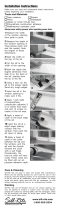
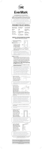 EverMark 303-066C Guía de instalación
-
Velux EDW MK06 0000 Guía de instalación
-
 Sill-Rite P364S Guía de instalación
-
The Home Depot 303-064C Guía de instalación
-
James Hardie 667421 Guía de instalación
-
Velux EDW M06 0000A Guía de instalación
-
Velux EDM C08 0000B Guía de instalación
-
James Hardie 9000306 Guía de instalación
-
Andersen PSBBGRORB Guía de instalación

