Faber Inca Lux 21 SSV with VAM Guía de instalación
- Categoría
- Campanas de cocina
- Tipo
- Guía de instalación
Este manual también es adecuado para

INLX21SSV
INLX28SSV
INLX35SSV
INCA LUX
Installation Instructions
Use and Care Information
Instructions d'installation
Utilisez et d'entretien
Instrucciones de instalación
Información de uso y cuidado

2
READ AND SAVE THESE INSTRUCTIONS BEFORE YOU START
INSTALLING THIS RANGEHOOD
WARNING: - TO REDUCE THE RISK OF A RANGE TOP GREASE FIRE:
a) Never leave surface units unattended at high settings. Boilovers cause smoking and
greasy spillovers that may ignite. Heat oils slowly on low or medium setting.
b)AlwaysturnhoodONwhencookingathighheatorwhenambeingfood(i.e.Crepes
Suzette, Cherries Jubilee, Peppercorn Beef Flambé).
c) Clean ventilating fans frequently. Grease should not be allowed to accumulate on fan
orlter.
d) Use proper pan size. Always use cookware appropriate for the size of the surface element.
WARNING: - TO REDUCE THE RISK OF INJURY TO PERSONS IN THE EVENT OF A
RANGE TOP GREASE FIRE, OBSERVE THE FOLLOWING*:
a)SMOTHERFLAMESwithaclose-ttinglid,cookiesheet,ormetaltray,thenturnofftheburner.
BECAREFULTOPREVENTBURNS.IftheamesdonotgooutimmediatelyEVACUATE
AND CALL THE FIRE DEPARTMENT.
b) NEVER PICK UP A FLAMING PAN - You may be burned.
c) DO NOT USE WATER, including wet dishcloths or towels - a violent steam explosion will
result.
d) Use an extinguisher ONLY if:
1. You know you have a Class ABC extinguisher, and you already know how to operate it.
2. Thereissmallandcontainedintheareawhereitstarted.
3. Theredepartmentisbeingcalled.
4. Youcanghttherewithyourbacktoanexit.
* Based on "Kitchen Firesafety Tips" published by NFPA
WARNING - TO REDUCE THE RISK OF FIRE OR ELECTRIC SHOCK, do not use this
fan with any solid-state speed control device.
WARNING - TO REDUCE THE RISK OF FIRE, ELECTRICAL SHOCK, OR INJURY TO
PERSONS, OBSERVE THE FOLLOWING:
1. Use this unit only in the manner intended by the manufacturer. If you have any
questions, contact the manufacturer.
2. Before servicing or cleaning unit, switch power off at service panel and lock the
service disconnecting means to prevent power from being switched on acciden-
tally. When the service disconnecting means cannot be locked, securely fasten a
prominent warning device, such as a tag, to the service panel.
CAUTION: For General Ventilating Use Only. Do Not Use To Exhaust Hazardous or
Explosive Materials and Vapors.
WARNING - TO REDUCE THE RISK OF FIRE, ELECTRICAL SHOCK, OR INJURY TO
PERSONS, OBSERVE THE FOLLOWING:
1. InstallationWorkAndElectricalWiringMustBeDoneByQualiedPerson(s)InAccor-
dance With All Applicable Codes And Standards, Including Fire-Rated Construction.
2. Sufcientairisneededforpropercombustionandexhaustingofgasesthrough
theue(chimney)offuelburningequipmenttopreventbackdrafting.Followthe
heating equipment manufacturer's guideline and safety standards such as those
publishedbytheNational FireProtectionAssociation(NFPA), and the American
SocietyforHeating,RefrigerationandAirConditioningEngineers(ASHRAE),and
the local code authorities.

3
3. When cutting or drilling into wall or ceiling, do not damage electrical wiring and
other hidden utilities.
4. Ducted fans must always be vented to the outdoors.
ALL WALL AND FLOOR OPENINGS WHERE THE RANGEHOOD IS INSTALLED MUST
BE SEALED.
This rangehood requires at least 24" of clearance between the bottom of the rangehood
and the cooking surface or countertop. This hood has been approved by UL at this distance from
the cooktop.
This minimum clearance may be higher depending on local building codes. For gas cooktops and
combination ranges, a minimum of 30" is recommended and may be required.
Overhead cabinets on both sides of this unit must be a minimum of 18" above the cooking surface
or countertop. Consult the cooktop or range installation instructions given by the manufacturer
before making any cutouts.
MOBILE HOME INSTALLATION The installation of this rangehood must conform to the Manufactured
Home Construction and Safety Standards, Title 24 CFR, Part 3280 (formerly Federal Standard
for Mobile Home Construction and Safety, Title 24, HUD, Part 280). See Electrical Requirements.
• Venting system MUST terminate outside the home.
• DO NOT terminate the ductwork in an attic or other enclosed space.
• DO NOT use 4" laundry-type wall caps.
• Flexible-type ductwork is not recommended.
• DO NOT obstruct the ow of combustion and ventilation air.
• Failure to follow venting requirements may result in a re.
WARNING
!
VENTING REQUIREMENTS
Determine which venting method is best for your application. Ductwork can extend either through the
wall or the roof.
The length of the ductwork and the number of elbows should be kept to a minimum to provide efcient
performance. The size of the ductwork should be uniform. Do not install two elbows together. Use
duct tape to seal all joints in the ductwork system. Use caulking to seal exterior wall or oor opening
around the cap.
Flexible ductwork is not recommended. Flexible ductwork creates back pressure and air turbulence
that greatly reduces performance.
Make sure there is proper clearance within the wall or oor for exhaust duct before making cutouts.
Do not cut a joist or stud unless absolutely necessary. If a joist or stud must be cut, then a supporting
frame must be constructed.
WARNING - To Reduce The Risk Of Fire, Use Only Metal Ductwork.
CAUTION-Toreduceriskofreandtoproperlyexhaustair,besuretoductairoutside–Do
not vent exhaust air into spaces within walls or ceilings or into attics, crawl spaces, or garages.

4
• Electrical ground is required on this rangehood.
• If cold water pipe is interrupted by plastic, nonmetallic gaskets or other materials, DO
NOT use for grounding.
• DO NOT ground to a gas pipe.
• DO NOT have a fuse in the neutral or grounding circuit. A fuse in the neutral or
grounding circuit could result in electrical shock.
• Check with a qualied electrician if you are in doubt as to whether the rangehood is
properly grounded.
• Failure to follow electrical requirements may result in a re.
WARNING
!
StateofCaliforniaProposition65Warning(USonly)
WARNING
This product contains chemicals known to the State of California to cause cancer and birth
defects or other reproductive harm.
For more information go to www.P65Warnings.ca.gov

5
RANGEHOOD DIMENSIONS
³³
³
³
³
³
³
Min. 24" Min.30"
47 "

6
MAIN PARTS
Components
Ref. Qty. Product Components
1 1 Hood Body, complete with: Con-
trols, Light, Filters, Blower.
2 1 Frame
8 1 Recirculation Vent Grill
10 1 Damper ø 5 7/8"
Ref. Qty. Installation Components
12a 10 Screws (for hood installation)
12e 2 Screws 1/8"x3/8" (for Recircula
tion Vent Grill mounting)
12f 6 Screws 1/8"x5/16" torx (for
frame mounting)
Qty. Documentation
1 Instruction Manual
H
I
H
I
H
I
Available Accessories
Parts needed
- 6" Round Metal ductwork .
Direct Connect Wiring Box sku # WIREBOX
Liner 24" Stainless #LINE24ST (Use only with INLX21SSV)
Liner 30" Stainless #LINE30ST (Use only with INLX28SSV)
Liner 36" Stainless #LINE36ST (Use only with INLX28SSV)
Liner 36" Stainless #LINE36PT (Use only with INLX28SSV)
Activated Charcoal Filter sku #; FILTER1
Long Lasting Activated Charcoal Filter sku# FILTER1LL
Remote Control Accessory - REMCTRL2
Created by
-
Denomination
-
Lang EN
Sheet
1
/1
Modif.by
Approved by
Approval date
Doc. status
Drawing N.
NEW_DRAWING_BOX
Rev
01

7
Choose your ducting method
Requires
purchase of
Activated
Charcoal
Accessory
Rear
Top
6"
The Electrical Connection and Ground Cable must
be disconnected rst before installation;
1. Disconnect the Electrical Connector as shown in
the gure. Depress the two tabs on the side of the
Electrical Connector using your hand and a small
at head screwdriver and pull off.
2. Next disconnect the Electrical ground cable(green)
that is attached with nuts and screw in the upper cav
-
ity of the insert. Unscrew and remove the electrical
ground nuts and washers using a 7mm small wrench
and a Philips screwdriver. Only remove the nuts and
washers on the inside of the cavity.
3. After removing the electrical ground cable nuts
and washers you can now remove the bottom frame
and set it aside.
Install the rangehood
(FollowthesestepsbeforeattemptingtoinstalltheInsert)
H
I
1
Non Ducted - RecirculationDucted Venting Installation

8
10 1/4”
1/2”
19
1/2
” - 26
9/16
” - 32
7/8
”
EN
7
7
INSTALLATION
Fitting the Hood canopy
BEFORE FITTING THE HOOD TO THE WALL UNIT, PROCEED AS FOLLOWS:
• Disconnect the wires to the Commands at the connectors.
• Disconnect the wires to the Light at the con-
nectors.
• The Hood can be installed directly on the
underside of
the wall unit (Minimum 650 mm
from the Cooker Hob).
• Create an opening in the bottom of the wall unit,
as shown.
• Insert the hood until the side supports snap into
place.
• Fasten using the 10 screws 12a provided.
• Lock in position by tightening the screws Vf from
underneath the hood.
• Open the suction panel by turning the specific knob.
• Disconnect the panel from the hood canopy by sliding the
fixing pin lever.
• Remove grease filters.
• Screw the Frame into place
using the 6 scr
ews 12f, re-
connect the wires to the
Commands and Light, re-
place the metal grease filter
and the Panel.
260
13
495 - 675
Vf
The Hood can be installed directly on the underside of the wall unit
(Minimum 24" - 30" from the Cooking Surface).
Create an opening in the bottom of the wall unit, as shown.
Insert the hood until the side supports snap into place.
Fasten using the 10 screws 12a provided.
Lock in position by tightening the screws Vf from underneath the hood.
Open the lter cover panel by turning the specic knob.
Disconnect the panel from the hood canopy by sliding the xing
pin levers.
Remove grease lters
and set aside.
Screw the Frame into place using the 6 screws
12f(1/8"x5/16" torx), reconnect the wires to the
Connector and the
Electrical ground cable (Yellow/
Green) removed previously. R
eplace the metal grease
lter and the Panel.

9
Choose your ducting method
Ducted Venting Installation
2
Non Ducted -
Recirculation Option
Install Damper that is included with the
Hood before connecting to the ductwork.
H
I
H
I
Install Roof or Wall Cap purchased
separately. Connect the 6" metal duct-
work to the Roof or Wall Cap and then
attach ductwork.
´
For Non-Ducted Recirculation venting route
the ductwork to a location above the hood
where the discharge is vented back into the
room.
Use the included Recirculation Vent Grill to
cover the opening. Secure the grill with the
2 screws provided in the Install Kit.
Required Activated Charcoal
Filter Accessory - sku # -
FILTER1
Long Lasting Activated Charcoal
Filter Accessory - sku #
FILTER1LL
(purchased separately)

10
3
Direct Connect Wiring Box
Accessory sku # WIREBOX
(purchased separately)
Created by
-
Denomination
-
Lang EN
Sheet
1
/1
Modif.by
Approved by
Approval date
Doc. status
Drawing N.
NEW_DRAWING_BOX
Rev
01
ELECTRICAL INSTALLATION WITH CONNECTION CABLE
ELECTRICAL INSTALLATION WITH
OPTIONAL WIRING BOX
For Permanent wiring Installation-Use only
with Listed rangehood Wiring Box kit
sku # WIREBOX, manufactured by Faber.
Max. 33 7/16”
GROUNDING INSTRUCTIONS This appliance must
be grounded. In the event of an electrical short circuit,
grounding reduces the risk of electric shock by providing
an escape wire for the electric current. This appliance
is equipped with a cord having a grounding wire with a
grounding plug. The plug must be plugged into an outlet
that is properly installed and grounded.
WARNING - Improper grounding can result in a risk of
electric shock.
Consult a qualied electrician if the grounding instructions
are not completely understood, or if doubt exists as to
whether the appliance is properly grounded.
Do not use an extension cord. If the power supply cord
is too short, have a qualied electrician install an outlet
near the appliance.
1
2
H
I
4
For Non-Ducted Recirculation Option
Attach each charcoal lter to the black
grid on each side of the blower. Press the
charcoal lter tightly to the black grid on the
blower side and rotate the lter clockwise
(towards the front of the insert hood) until
it locks into place. Turn counterclockwise
(towards the back of the insert hood) to
remove.
Required Activated Charcoal Filter
Accessory - sku # - FILTER1
Long Lasting Activated Charcoal Filter
Accessory - sku # FILTER1LL
(purchased separately)

11
1
2
Replace the grease lters removed
previously.
H
I
5
Close the lter panel
cover by pushing it back
into place until the latch
mechanism has secured it.
H
I
6

12
Cleaning Filter Cover Panel
• Open the Panel by pulling it.
• Clean the outside with a damp cloth and neutral
detergent.
• Clean the inside using a damp cloth and neutral
detergent do not use wet cloths or sponges, or
jets of water; do not use abrasive substances.
H
I
USE AND CARE INFORMATION
T1 T2 T3 T4 L
LT1 T2 T3 T4
For Best Results
Start the rangehood several minutes before cooking to develop proper airow. Allow the
rangehood to operate for several minutes after cooking is complete to clear all smoke and
odors from the kitchen.
T1. Fan off button:turn the blower Off. The fan can be operated by pressing any of the fan setting buttons.
Hold down this button for 2 seconds to activate Delay off function which will keep the fan on for 15
minutes and automatically shut off.
T2. Fan settings buttons: Low speed.
T3. Fan settings buttons: Medium speed.
T4. Fan settings buttons: High speed / Intensive speed.
Hold down the button for 2 seconds to activate the intensive speed, which is timed to run for 6
minutes. At the end of this time it will automatically return to the speed set before.Suitable to deal
with maximum levels of cooking fumes.
L. Light button: On/Off switch for the lights.
NOTE: If your product has had a CFM adjustment, refer to the CFM adjustment manual for the infor
-
mation. Some motor speeds or functions may be reduced.

13
Cleaningmetalgreaselters
The metal grease lters can be cleaned in hot detergent solution or
washed in the dishwasher. They should be cleaned every 2 months
use, or more frequently if use is particularly heavy.
• Open the Panel by pulling it.
• Remove the lter, pushing the lever towards the back of the unit
and at the same time pulling downward.
• Wash the lter without bending it, leave it to dry thoroughly before
replacing (if the surface of the lter changes color over time, this
will have absolutely no effect on its efciency).
• Replace, taking care to ensure that the handle faces forward.
• Cleaning in dishwasher may dull the nish of the metal grease
lter.
• Close the Panel.
• No water can be present in lters before installing back in hood.
Replacing Activated Charcoal Filter
The Activated Charcoal Filters are not washable and cannot
be regenerated, and must be replaced approximately every 4
months of operation, or more frequently with heavy usage.
• Open the Panel by pulling it.
• Remove the Filter, pushing it towards the back of the unit and
at the same time pulling downward.
• Remove the saturated Activated Charcoal Filters, as indicated
(A).
• Fit the new Filters, as indicated (B).
• Replace, taking care to ensure that the handle faces forwards.
• Close the Panel.
Caution: "When used in recirculation mode, to Reduce
the Risk of Fire and Shock use only conversion kit Model
FILTER 1 or FILTER1LL"
EN
7
7
INSTALLATION
Fitting the Hood canopy
BEFORE FITTING THE HOOD TO THE WALL UNIT, PROCEED AS FOLLOWS:
• Disconnect the wires to the Commands at the connectors.
• Disconnect the wires to the Light at the con-
nectors.
• The Hood can be installed directly on the
underside of
the wall unit (Minimum 650 mm
from the Cooker Hob).
• Create an opening in the bottom of the wall unit,
as shown.
• Insert the hood until the side supports snap into
place.
• Fasten using the 10 screws 12a provided.
• Lock in position by tightening the screws Vf from
underneath the hood.
• Open the suction panel by turning the specific knob.
• Disconnect the panel from the hood canopy by sliding the
fixing pin lever.
• Remove grease filters.
• Screw the Frame into place
using the 6 scr
ews 12f, re-
connect the wires to the
Commands and Light, re-
place the metal grease filter
and the Panel.
260
13
495 - 675
Gu10 self-ballasted led lamps
– listed in accordance with ul
1993/nmx-j-578/1-ance/csa
c22.2 No. 1993
Lighting unit
• Replace the lamp with a new one of the same type,
making sure that you insert the two pins properly into
the housings on the lamp holder.
a
b
a
b

14
Wiring Diagram
991.0530.011 H90-503
D00004494_00
991.0530.011 H90-503
D00004494_00
120V 60Hz

15
January 4, 2016
FABER CONSUMER WARRANTY & SERVICE
All Faber products are warranted against any defect in materials or workmanship for the original purchaser
for a period of 1 year from the date of original purchase (requires proof of purchase). This warranty covers
labor and replacement parts. Faber, at its option, may repair or replace the product or components
necessary to restore the product to good working condition. To obtain warranty service, contact the dealer
from whom you purchased the range hood, or the local Faber distributor. If you cannot identify a local Faber
distributor, contact us at (508) 358-5353 for the name of a distributor in your area.
The following is not covered by Faber's warranty:
1. Service calls to correct the installation of your range hood, to instruct you how to use your range hood, to
replace or repair house fuses or to correct house wiring or plumbing.
2. Service calls to repair or replace range hood light bulbs, fuses or filters. Those consumable parts are
excluded from warranty coverage.
3. Repairs when your range hood is used for other than normal, single-family household use.
4. Damage resulting from accident, alteration, misuse, abuse, fire, flood, acts of God, improper installation,
installation not in accordance with electrical or plumbing codes or Faber documentation, or use of products
not approved by Faber.
5. Replacement parts or repair labor costs for units operated outside the United States or Canada, including
any non-UL or C-UL approved Faber range hoods.
6. Repairs to the hood resulting from unauthorized modifications made to the range hood.
7. Expenses for travel and transportation for product service in remote locations and pickup and delivery
charges. Faber range hoods should be serviced in the home.
THIS WARRANTY DOES NOT ALLOW RECOVERY OF INCIDENTAL OR CONSEQUENTIAL DAMAGES, INCLUDING, WITHOUT
LIMITATION, DIRECT, INDIRECT, INCIDENTAL, SPECIAL OR CONSEQUENTIAL DAMAGES, PERSONAL INJURY/WRONGFUL
DEATH OR LOST PROFITS FABER WARRANTY IS LIMITED TO THE ABOVE CONDITIONS AND TO THE WARRANTY PERIOD
SPECIFIED HEREIN AND IS EXCLUSIVE. EXCEPT AS EXPRESSLY SPECIFIED IN THIS AGREEMENT, FABER DISCLAIMS ALL
EXPRESS OR IMPLIED CONDITIONS, REPRESENTATIONS, AND WARRANTIES INCLUDING, WITHOUT LIMITATION, ANY
IMPLIED WARRANTIES OF MERCHANTABILITY OR FITNESS FOR A PARTICULAR PURPOSE
.
This warranty gives you specific legal rights that may vary from state to state.
Model#: ______________________________ Serial #: _____________________________

16
VEUILLEZ LIRE ET CONSERVER LA PRÉSENTE NOTICE AVANT DE
COMMENCER L'INSTALLATION DE LA HOTTE DE CUISINE
AVERTISSEMENT:-POUR RÉDUIRE LE RISQUE D'UN FEU DE GRAISSE SUR LA TABLE DE
CUISSON:
a) Ne laissez jamais sans surveillance les éléments de la surface de cuisson à température élevée.
Les bouillonnements excessifs peuvent provoquer de la fumée et les débordements de graisse
peuvents'enammer.L'huiledoitêtrechaufféelentement,àunetempératurebasseoumoyenne.
b) Assurez-vous de toujours mettre en marche le ventilateur de la hotte lorsque vous cuisinez
àtempératureélevéeoupréparezunmetsambé(p.ex.crêpesSuzette,cerisesjubilé,bœuf
ambé).
c) Nettoyez régulièrement les ventilateurs d'aspiration. Assurez-vous de ne pas laisser de la graisse
s'accumulersurleventilateurouleltre.
d)Utiliseztoujoursdespoêlesetcasserolesdelatailleappropriée.Utiliseztoujoursdesustensiles
de cuisine de la taille adaptée à celle de l'élément chauffant.
AVERTISSEMENT:-POURPRÉVENIRLESBLESSURESENCASDEFEUDEGRAISSESURLA
TABLEDECUISSON,SUIVEZLESRECOMMANDATIONSSUIVANTES*:
a) ÉTOUFFEZ LES FLAMMES à l'aide d'un couvercle hermétique, d'une plaque à biscuits ou d'un
plateau métallique, puis éteignez le brûleur. FAITES ATTENTION AUX BRÛLURES. Si le feu ne
s'éteint pas immédiatement, QUITTEZ LES LIEUX ET APPELEZ LES POMPIERS.
b) NE PRENEZ JAMAIS UNE CASSEROLE EN FLAMME - Vous pourriez vous brûler.
c) N'UTILISEZ JAMAIS DE L'EAU, ni un linge à vaisselle ou un torchon mouillé, pour éteindre le feu.
Cela pourrait provoquer une violente explosion de vapeur.
d)UtilisezunextincteurUNIQUEMENTsi:
1. Vousêtescertainqu'ils'agitd'unextincteurdeclasseABCetquevousconnaissezbienson
mode d'emploi.
2. Le feu est de faible intensité et se limite à l'endroit où il a démarré.
3. Les pompiers ont déjà été appelés.
4. Unevoiedesortiesetrouvederrièrevouspendantquevouséteignezlesammes
* D'après le guide «Kitchen Firesafety Tips» publié par la NFPA aux États-Unis
AVERTISSEMENT - POUR RÉDUIRE LE RISQUE D'INCENDIE OU DE CHOC ÉLECTRIQUE, n'utilisez
jamais ce ventilateur en association avec un dispositif de réglage de vitesse à semi-conducteurs.
AVERTISSEMENT - POUR RÉDUIRE LES RISQUES D'INCENDIE, DE CHOC ÉLECTRIQUE OU DE
BLESSURECORPORELLE,RESPECTEZLESINSTRUCTIONSSUIVANTES:
1. Utilisez cet appareil uniquement de la façon prévue par le fabricant. Pour toute question, com-
muniquez avec le fabricant.
2. Avant de procéder à l'entretien ou au nettoyage de l'appareil, coupez l'alimentation au niveau du
panneau électrique et verrouillez-le pour vous assurer que l'électricité n'est pas rétablie accidentel-
lement.S'iln'estpaspossibledeverrouillerledispositifd'interruptiondel'alimentation,afchezde
façon ferme et bien visible un avis de danger, par exemple à l'aide d'une étiquette sur le panneau.
ATTENTION:Destinéàunusagedeventilationgénéraleuniquement.N'utilisezpascedispositif
pour l'aspiration de vapeurs ou de matériaux dangereux ou explosifs.
AVERTISSEMENT - POUR RÉDUIRE LES RISQUES D'INCENDIE, DE CHOC ÉLECTRIQUE OU DE
BLESSURECORPORELLE,RESPECTEZLESINSTRUCTIONSSUIVANTES:
1. L'installationetlebranchement électriquedoiventêtreréalisésparun technicienqualiéet
conformément à tous les codes et normes en vigueur, incluant ceux concernant la construction
à l'épreuve du feu.
2. Andegarantirunecombustionetuneévacuationadéquatesdesgazparlesconduitesdela
cheminée des appareils à combustion, une bonne aération est nécessaire pour éviter le refou-
lement. Respectez les lignes directrices fournies par le fabricant du matériel chauffant, ainsi que
lesnormesdesécuritécommecellespubliéesparlaNationalFireProtectionAssociation(NFPA)
etlaAmericanSocietyforHeating,RefrigerationandAirConditioningEngineers(ASHRAE)aux
États-Unis, ainsi que les codes en vigueur dans votre région.

17
3. Lorsque vous faites une ouverture ou percez dans un mur ou le plafond, veillez à ne pas
endommagerleslsélectriquesoud'autresdispositifscachés.
4. Lesventilateurscanalisésdoiventtoujoursêtreraccordésàl'extérieur.
TOUTE OUVERTURE DANS LE MUR OU LE PLANCHER À PROXIMITÉ DE LA
HOTTE DOIT ÊTRE SCELLÉE.
Un espace libre d'au moins 24" est requis entre le bas de la hotte et la surface de cuisson
ou le comptoir. Cette hotte a été homologuée par l'UL à cette distance de la surface de cuisson.
L’espace libre minimal requis peut-être plus grand, selon la réglementation en matière de
construction de votre région. Pour les cuisinières à gaz et les cuisinières combinées, un
espace minimal de 30" est recommandé et pourrait être exigé.
Les armoires suspendues de chaque côté de l'appareil doivent se trouver à au moins 18"
de la surface de cuisson ou du comptoir. Consultez la notice d'installation de la surface de
cuisson ou de la cuisinière fournie par le fabricant avant de pratiquer des ouvertures.
INSTALLATION DANS UNE MAISON MOBILE L'installation de cette hotte doit être conforme
à la Partie 3280 de la norme Manufactured Home Construction and Safety Standards, Title 24
CFR (précédemment la partie 280 de la norme Federal Standard for Mobile Home Construction
and Safety, Title 24, HUD). Consultez la che technique électrique.
• Le système de ventilation DOIT déboucher à l'extérieur.
• NE FAITES PAS déboucher les conduits dans un grenier ou un autre endroit fermé.
• N'UTILISEZ PAS un clapet de sécheuse mural de 4po.
• Il n'est pas recommandé d'utiliser des conduits exibles.
• N'ENTRAVEZ PAS le ux de l'air de combustion et de ventilation.
• Le non-respect des exigences en matière de ventilation pourrait entraîner un incendie.
AVERTISSEMENT
!
CRITÈRES DE VENTILATION
Déterminez quelle méthode de ventilation est mieux adaptée à votre application. Les conduits peuvent
passer par le mur ou le toit.
Pour garantir une meilleure efcacité, la longueur des conduits et le nombre de coudes doivent être le plus
limités que possible. Le diamètre des conduits devrait être uniforme. N'installez pas deux coudes ensemble.
Utilisez un ruban pour canalisations an de sceller tous les joints du système de conduits. Utilisez un calfeu
-
trage pour sceller les ouvertures dans le mur extérieur ou le plancher, autour du clapet.
Il n'est pas recommandé d'utiliser des conduits flexibles. Les conduits flexibles provoquent une contre-pression
et de la turbulence qui diminuent grandement l'efficacité de l'appareil.
Assurez-vous que l'espace libre dans le mur ou le plancher est sufsant pour le conduit d'évacuation avant de
pratiquer les ouvertures. Ne coupez jamais une poutre ou un chevron, sauf si c'est absolument nécessaire.
S'il s'avère nécessaire de couper une poutre ou un chevron, la construction d'un renforcement est requise.
AVERTISSEMENT - Pour réduire le risque d'incendie, utilisez uniquement des conduits métalliques.
ATTENTION - Pour réduire le risque d'incendie et pour évacuer adéquatement l'air, assurez-vous
deraccorderlesconduitsàl'extérieur–Nediffusezpasl'aird'évacuationdansdesespacesà
l'intérieur des murs ou du plafond, ou encore à l'intérieur d'un grenier, d'une galerie technique
ou d'un garage.

18
• Une mise à la terre électrique est requise pour cette hotte.
• N'UTILISEZ PAS un tuyau d'eau froide pour la mise à la terre si celui-ci est branché par des
joints en plastique, par des rondelles non métalliques ou d'autres matériaux.
• N'UTILISEZ PAS une conduite de gaz pour la mise à la terre.
• N'INSTALLEZ PAS un fusible sur le circuit neutre ou le circuit de mise à la terre. La présence
d'un fusible dans le circuit neutre ou de mise à la terre peut entraîner un choc électrique.
• Consultez un électricien qualié si vous n'êtes pas certain de la mise à la terre de la hotte.
• Le non-respect des exigences de la che technique électrique pourrait entraîner un incendie.
AVERTISSEMENT
!
Avertissementdelaproposition65del'ÉtatdeCalifornie(USseulement)
ATTENTION
Ce produit contient des produits chimiques connus de l'État de Californie pour causer le
cancer et des malformations congénitales ou d'autres problèmes de reproduction.
Pour plus d'informations, visitez www.P65Warnings.ca.gov

19
DIMENSIONS DE LA HOTTE
Min. 24" Min.30"
³³
³
³
³
³
³
47 "

20
PIÈCES PRINCIPALES
Composants
Réf. Qté Composants du produit
1 1 Bâti de la hotte, avec : Com-
mandes, éclairages, ltres,
ventilateur.
2 1 Bâti
8 1 Grille d'évent de recirculation
10 1 Registre ø 5 7/8"
Réf. Qté Composants d'installation
12a 10 Vis (pour installation de la hotte)
12e 2 Vis 1/8"x3/8" (pour montage de
la grille d'évent de recir culation)
12f 6 Vis 1/8"x5/16" torx (pour mon
tage du bâti)
Qté Documentation
1 Mode d'emploi
H
I
H
I
H
I
Accessoires disponibles
Pièces requises
- Conduit métallique 6" circulaire.
No d'article - Boîtier de connexion directe : WIREBOX
Doublure 24" acier inoxydable, no LINE24ST (Utiliser uniquement avec INLX21SSV)
Doublure 30" acier inoxydable, no LINE30ST (Utiliser uniquement avec INLX28SSV)
Doublure 36" acier inoxydable, no LINE36ST (Utiliser uniquement avec INLX28SSV)
Doublure 36" acier inoxydable, no LINE36PT (Utiliser uniquement avec INLX28SSV)
Filtre à charbon actif No d'article FILTER1
Filtre à charbon actif de longue durée No d'article FILTER1LL
Télécommande accessoire - REMCTRL2
Created by
-
Denomination
-
Lang EN
Sheet
1
/1
Modif.by
Approved by
Approval date
Doc. status
Drawing N.
NEW_DRAWING_BOX
Rev
01

21
Choisissez la méthode de canalisation
Exige
l'achat de
l'accessoire
à charbon
actif
6"
Le branchement électrique et le câble de mise à la
terre doivent être débranchés avant l'installation;
1. Débranchez le connecteur électrique comme
illustré. Enfoncez les deux pattes sur le côté du
connecteur électrique à l'aide de la main et d'un
petit tournevis à lame plate et tirez pour l'enlever.
2. Débranchez ensuite le câble de mise à la terre
électrique (vert) qui est xé à l'aide d'écrous
et de vis dans la cavité supérieure de la hotte
encastrable. Dévissez et retirez les écrous
et rondelles de la mise à la terre électrique à
l'aide d'une petite clé de 7 mm et d'un tournevis
cruciforme. Retirez uniquement les écrous et
rondelles à l'intérieur de la cavité.
3. Après avoir retiré les écrous et rondelles du
câble de mise à la terre électrique, vous pouvez
retirer la partie inférieure du bâti et le mettre à part.
Installer la hotte
(Suivezcesprocéduresavantd'entreprendrel'installationdelahotteencastrable)
H
I
1
Sans canalisation - RecirculationInstallation avec ventilation canalisée
Arrière
Haut

22
10 1/4”
1/2”
19
1/2
” - 26
9/16
” - 32
7/8
”
EN
7
7
INSTALLATION
Fitting the Hood canopy
BEFORE FITTING THE HOOD TO THE WALL UNIT, PROCEED AS FOLLOWS:
• Disconnect the wires to the Commands at the connectors.
• Disconnect the wires to the Light at the con-
nectors.
• The Hood can be installed directly on the
underside of
the wall unit (Minimum 650 mm
from the Cooker Hob).
• Create an opening in the bottom of the wall unit,
as shown.
• Insert the hood until the side supports snap into
place.
• Fasten using the 10 screws 12a provided.
• Lock in position by tightening the screws Vf from
underneath the hood.
• Open the suction panel by turning the specific knob.
• Disconnect the panel from the hood canopy by sliding the
fixing pin lever.
• Remove grease filters.
• Screw the Frame into place
using the 6 scr
ews 12f, re-
connect the wires to the
Commands and Light, re-
place the metal grease filter
and the Panel.
260
13
495 - 675
EN
7
7
INSTALLATION
Fitting the Hood canopy
BEFORE FITTING THE HOOD TO THE WALL UNIT, PROCEED AS FOLLOWS:
• Disconnect the wires to the Commands at the connectors.
• Disconnect the wires to the Light at the con-
nectors.
• The Hood can be installed directly on the
underside of
the wall unit (Minimum 650 mm
from the Cooker Hob).
• Create an opening in the bottom of the wall unit,
as shown.
• Insert the hood until the side supports snap into
place.
• Fasten using the 10 screws 12a provided.
• Lock in position by tightening the screws Vf from
underneath the hood.
• Open the suction panel by turning the specific knob.
• Disconnect the panel from the hood canopy by sliding the
fixing pin lever.
• Remove grease filters.
• Screw the Frame into place
using the 6 scr
ews 12f, re-
connect the wires to the
Commands and Light, re-
place the metal grease filter
and the Panel.
260
13
495 - 675
EN
7
7
INSTALLATION
Fitting the Hood canopy
BEFORE FITTING THE HOOD TO THE WALL UNIT, PROCEED AS FOLLOWS:
• Disconnect the wires to the Commands at the connectors.
• Disconnect the wires to the Light at the con-
nectors.
• The Hood can be installed directly on the
underside of
the wall unit (Minimum 650 mm
from the Cooker Hob).
• Create an opening in the bottom of the wall unit,
as shown.
• Insert the hood until the side supports snap into
place.
• Fasten using the 10 screws 12a provided.
• Lock in position by tightening the screws Vf from
underneath the hood.
• Open the suction panel by turning the specific knob.
• Disconnect the panel from the hood canopy by sliding the
fixing pin lever.
• Remove grease filters.
• Screw the Frame into place
using the 6 scr
ews 12f, re-
connect the wires to the
Commands and Light, re-
place the metal grease filter
and the Panel.
260
13
495 - 675
EN
7
7
INSTALLATION
Fitting the Hood canopy
BEFORE FITTING THE HOOD TO THE WALL UNIT, PROCEED AS FOLLOWS:
• Disconnect the wires to the Commands at the connectors.
• Disconnect the wires to the Light at the con-
nectors.
• The Hood can be installed directly on the
underside of
the wall unit (Minimum 650 mm
from the Cooker Hob).
• Create an opening in the bottom of the wall unit,
as shown.
• Insert the hood until the side supports snap into
place.
• Fasten using the 10 screws 12a provided.
• Lock in position by tightening the screws Vf from
underneath the hood.
• Open the suction panel by turning the specific knob.
• Disconnect the panel from the hood canopy by sliding the
fixing pin lever.
• Remove grease filters.
• Screw the Frame into place
using the 6 scr
ews 12f, re-
connect the wires to the
Commands and Light, re-
place the metal grease filter
and the Panel.
260
13
495 - 675
EN
7
7
INSTALLATION
Fitting the Hood canopy
BEFORE FITTING THE HOOD TO THE WALL UNIT, PROCEED AS FOLLOWS:
• Disconnect the wires to the Commands at the connectors.
• Disconnect the wires to the Light at the con-
nectors.
• The Hood can be installed directly on the
underside of
the wall unit (Minimum 650 mm
from the Cooker Hob).
• Create an opening in the bottom of the wall unit,
as shown.
• Insert the hood until the side supports snap into
place.
• Fasten using the 10 screws 12a provided.
• Lock in position by tightening the screws Vf from
underneath the hood.
• Open the suction panel by turning the specific knob.
• Disconnect the panel from the hood canopy by sliding the
fixing pin lever.
• Remove grease filters.
• Screw the Frame into place
using the 6 scr
ews 12f, re-
connect the wires to the
Commands and Light, re-
place the metal grease filter
and the Panel.
260
13
495 - 675
Vf
La hotte peut être installée directement sur la face inférieure de
l'unité murale (à au moins 24" - 30" de la surface de cuisson).
Pratiquez une ouverture sur le fond de l'unité murale, comme
illustré.
Insérez la hotte jusqu'à ce que les appuis latéraux s'enclenchent.
Fixez-la à l'aide des 10 vis 12a fournies.
Verrouillez en serrant les vis Vf du dessous de la hotte.
Ouvrez le panneau de protection du ltre en tournant le bouton
requis.
Détachez le panneau de l'auvent de la hotte en faisant glisser les
leviers des chevilles de xation.
Retirez les ltres à graisse
et mettez-les à part.
Vissez le bâti en place à l'aide des 6 vis
12f(1/8"x5/16" torx), et rebranchez les câbles
au connecteur et le câble de mise à la terre
électrique (jaune/vert) retirés précédemment.
Remettez en place le ltre à graisse métallique et
le panneau.

23
2
H
I
H
I
´
Choisissez la méthode de canalisation
Installation avec
ventilation canalisée
Sans canalisation -
Option de recirculation
Installez le registre inclus avec la hotte
avant de la raccorder aux conduits.
Pour la ventilation avec recirculation sans
canalisation, dirigez les conduits à un
emplacement au-dessus de la hotte où
l'air évacué est retourné dans la pièce.
Utilisez la grille d'évent de recirculation
pour couvrir l'ouverture. Fixez la grille à
l'aide des 2 vis fournies dans la trousse
d'installation.
Installez le clapet de toiture ou le clapet
mural acheté séparément. Raccordez
le conduit métallique de 6" au clapet de
toiture ou au clapet mural, puis raccor-
dez les conduits.
Filtre à charbon actif accessoire
requis - no d'article - FILTER1
Filtre à charbon actif de longue
durée# FILTER1LL (acheté
séparément)

24
3
Boîtier de connexion directe,
no d'article WIREBOX
(acheté séparément)
Created by
-
Denomination
-
Lang EN
Sheet
1
/1
Modif.by
Approved by
Approval date
Doc. status
Drawing N.
NEW_DRAWING_BOX
Rev
01
Installation Électrique Avec Câble De Connexion
INSTALLATION ÉLECTRIQUE
AVEC BOÎTIER DE CONNEXION EN
OPTION
Pour une installation avec connexion xe,
utilisez uniquement la trousse de boîtier de
connexion pour hotte indiquée, no d'article
WIREBOX, fabriquée par Faber.
Max. 33 7/16”
INSTRUCTIONS DE MISE À LA TERRE Cet appareil doit
être mis à la terre. La mise à la terre réduit le risque de
choc électrique en cas de court-circuit, car elle fournit un l
d'évacuation au courant électrique. Cet appareil est muni
d'un cordon présentant un l de mise à la terre, avec une
che de mise à la terre. La che doit être insérée dans
une prise correctement installée et mise à la terre.
AVERTISSEMENT - Une mise à la terre inadéquate peut
entraîner un choc électrique.
Consultez un électricien qualié si vous ne comprenez pas
parfaitement les instructions de mise à la terre ou si vous
avez des doutes quant à la mise à la terre de l'appareil.
N'utilisez pas de rallonge. Si le cordon d’alimentation est
trop court, demandez à un électricien qualié d’installer
une prise à proximité de l'appareil.
1
2
H
I
4
Pour option non canalisée avec
recirculation d'air
Fixez les ltres à charbon à la grille noire
de chaque côté du ventilateur. Pressez
fermement le ltre à charbon contre la grille
noire de chaque côté du ventilateur et faites
tourner le ltre dans le sens des aiguilles
d'une montre (vers l'avant de la hotte
encastrable) jusqu'à ce qu'il soit verrouillé en
place. Faites tourner dans le sens contraire
des aiguilles d'une montre (vers l'arrière de
la hotte encastrable) pour l'enlever.
Filtre à charbon actif accessoire requis -
no d'article - FILTER1
Filtre à charbon actif de longue durée#
FILTER1LL (acheté séparément)

25
1
2
H
I
5
H
I
6
Replacez les ltres à graisse enlevés
précédemment.
Fermez le panneau de
protection du ltre en le
poussant en place jusqu'à
ce que le mécanisme de
verrouillage se déclenche.

26
Nettoyage du panneau de protection
dultre
• Ouvrez le panneau en le tirant.
• Nettoyez l'extérieur à l'aide d'un linge humide
et d'un détergent neutre.
• Nettoyez l'intérieur à l'aide d'un linge humide et
d'un détergent neutre. N'utilisez pas des linges
mouillés ou des éponges, un jet d'eau ou des
substances abrasives.
H
I
INFORMATIONS POUR L'UTILISATION ET L'ENTRETIEN
T1 T2 T3 T4 L
LT1 T2 T3 T4
Pour de meilleurs résultats
Activez la hotte quelques minutes avant de commencer à cuisiner pour créer un ux d'air
adéquat. Laissez la hotte fonctionner quelques minutes après avoir ni de cuisiner pour
absorber toute la fumée et les odeurs de la cuisine.
T1. Bouton arrêt du ventilateur : éteint le ventilateur. Le ventilateur peut être allumé en ap-
puyant sur l'un ou l'autre des boutons de réglage.
Tenez ce bouton enfoncé pendant 2 secondes pour activer la fonction de désactivation
retardée, qui éteindra automatiquement le ventilateur après 15 minutes de marche.
T2. Boutons de réglage du ventilateur : vitesse réduite.
T3. Boutons de réglage du ventilateur : vitesse moyenne.
T4. Boutons de réglage du ventilateur : vitesse élevée / vitesse intensive.
Tenez le bouton enfoncé pendant environ 2 secondes pour activer la vitesse intensive,
pour une durée de 6 minutes. Après ce délai, la vitesse retournera automatiquement à
la vitesse sélectionnée précédemment. Utile pour contrer les émanations maximales de
cuisson.
L. Bouton pour l'éclairage: commutateur marche/arrêt pour l'éclairage.
REMARQUE: Si votre produit a subi un réglage CFM, reportez-vous au manuel de réglage CFM
pour plus d'informations. Certaines vitesses de moteur des fonctions peuvent être réduites.

27
Nettoyagedesltresàgraissemétalliques
Les ltres à graisse métalliques peuvent être lavés dans une solution
d'eau chaude savonneuse ou dans le lave-vaisselle. Ils devraient
être nettoyés tous les 2 mois d'utilisation, ou plus fréquemment
en cas d'utilisation particulièrement intensive.
• Ouvrez le panneau en le tirant.
• Retirez le ltre, en poussant simultanément le levier vers l'arrière
de l'appareil et en le tirant vers le bas.
• Lavez le ltre sans le plier. Laissez-le sécher complètement
avant de le réinstaller (un changement de la couleur à la surface
du ltre au l du temps n'a aucun impact sur son efcacité).
• Remettez-le en place, en vous assurant que la poignée se
trouve vers l'avant.
• Le lave-vaisselle pourrait ternir le ni du ltre à graisse métallique.
• Refermez le panneau.
• Aucune eau ne peut être présente dans les ltres avant la
réinstallation dans la hotte.
Remplacementdultreàcharbonactif
Les ltres à charbon actif ne sont pas lavables et ne peuvent
être régénérés. Ils doivent être remplacés environ tous les 4 mois
d'utilisation, ou plus souvent en cas d'utilisation intensive.
• Ouvrez le panneau en le tirant.
• Retirez le ltre, en le poussant simultanément vers l'arrière de
l'appareil et en le tirant vers le bas.
• Retirez les ltres à charbon actif saturés comme indiqué (A).
• Posez les nouveaux ltres, comme indiqué (B).
• Remettez-le en place, en vous assurant que la poignée se
trouve vers l'avant.
• Refermez le panneau.
ATTENTION: Pour réduire le risque d’incendie ou de choc électrique
lorsque l’appareil est utilisé en mode recyclage, utilisez uniquement le
modèle FILTER 1 ou FILTER1LL en guise de trousse de conversion.
EN
7
7
INSTALLATION
Fitting the Hood canopy
BEFORE FITTING THE HOOD TO THE WALL UNIT, PROCEED AS FOLLOWS:
• Disconnect the wires to the Commands at the connectors.
• Disconnect the wires to the Light at the con-
nectors.
• The Hood can be installed directly on the
underside of
the wall unit (Minimum 650 mm
from the Cooker Hob).
• Create an opening in the bottom of the wall unit,
as shown.
• Insert the hood until the side supports snap into
place.
• Fasten using the 10 screws 12a provided.
• Lock in position by tightening the screws Vf from
underneath the hood.
• Open the suction panel by turning the specific knob.
• Disconnect the panel from the hood canopy by sliding the
fixing pin lever.
• Remove grease filters.
• Screw the Frame into place
using the 6 scr
ews 12f, re-
connect the wires to the
Commands and Light, re-
place the metal grease filter
and the Panel.
260
13
495 - 675
Système d'éclairage
• Remplacez l'ampoule avec une nouvelle du même
type, en vous assurant d'insérer correctement les
deux connecteurs dans leur logement sur le socle.
Lampes DEL à ballast intégré
de type Gu10 – répondant à la
norme UL 1993/nmx-j-578/1-
ance/csa c22.2 No 1993
a
b
a
b

28
Schéma de câblage
991.0530.011 H90-503
D00004494_00
991.0530.011 H90-503
D00004494_00
120V 60Hz

29
4 janvier 2016
GARANTIE LIMITÉE ET SERVICE FABER
Tous les produits Faber font l'objet d'une garantie contre les défauts de matériel et de main-
d'œuvre,accordée à l'acheteur original pour une période d'un (1) an à compter de la date d'achat initiale
(preuve d'achat requise). Cette garantie couvre les frais de main-d'œuvre et les pièces de rechange. À sa
discrétion, Faber peut réparer ou remplacer le produit ou les composants nécessaires à remettre le produit
en bon état de marche. Pour bénéficier de services prévus par la garantie, veuillez communiquer avec le
détaillant auprès duquel vous avez acheté la hotte de cuisine, ou encore avec le distributeur Faber de votre
région. Si vous n'êtes pas en mesure de localiser un distributeur Faber dans votre région, veuillez
communiquer avec nous au 508-358-5353 pour connaître le nom d'un distributeur à proximité.
Les éléments suivants ne sont pas visés par la garantie Faber :
1. Les appels au service de réparation visant à corriger l'installation de la hotte de cuisine, à recevoir des
instructions sur l'utilisation de la hotte de cuisine, le remplacement ou la réparation des fusibles du domicile
ou la correction des câblages ou de la plomberie du domicile.
2. Les appels au service de réparation visant à réparer ou remplacer les ampoules électriques de hotte, les
fusibles ou les filtres. Ces pièces consommables ne sont pas couvertes par la garantie.
3. Les réparations si votre hotte de cuisine est employée à des fins autres que celles prévues, soit l'utilisation
résidentielle normale pour une famille.
4. Les dommages découlant d'un accident, d'une modification, de l'utilisation incorrecte ou abusive, d'un
incendie, d'une inondation, d'un cas de force majeure, d'une installation inadéquate, d'une installation non
conforme aux codes en matière d'électricité ou de plomberie ou à la documentation fournie par Faber, ou
encore d'une utilisation du produit non approuvée par Faber.
5. Les frais de main-d'œuvre ou de remplacement des pièces pour les appareils utilisés à l'extérieur des
États-Unis ou du Canada, y compris toutes les hottes de cuisine Faber non-UL ou C-UL homologuées.
6. Les réparations à la hotte découlant de modifications non autorisées apportées à la hotte de cuisine.
7. Les frais encourus pour les déplacements et le transport de produits en région éloignée et les frais de
cueillette et livraison. La réparation des hottes de cuisine Faber doit être réalisée à domicile.
LA PRÉSENTE GARANTIE NE PRÉVOIT AUCUNE FORME DE DÉDOMMAGEMENT EN CAS DE DOMMAGES ACCESSOIRES OU
CONSÉCUTIFS, Y COMPRIS, SANS TOUTEFOIS S'Y LIMITER, LES DOMMAGES DIRECTS, INDIRECTS, ACCESSOIRES,
PARTICULIERS OU CONSÉCUTIFS, LES LÉSIONS CORPORELLES/MORTELLES OU LA PERTE DE PROFITS. LA GARANTIE
OFFERTE PAR FABER EST LIMITÉE AUX CONDITIONS ÉNONCÉES CI-DESSUS ET À LA PÉRIODE DE GARANTIE INDIQUÉE
DANS LES PRÉSENTES ET EST EXCLUSIVE. SAUF DISPOSITIONS EXPRESSES CONTRAIRES DANS LE PRÉSENT ACCORD,
FABER DÉCLINE TOUTE CONDITION, REPRÉSENTATION OU GARANTIE EXPLICITE OU IMPLICITE, Y COMPRIS, SANS
TOUTEFOIS S'Y LIMITER, TOUTE GARANTIE IMPLICITE DE QUALITÉ MARCHANDE OU D'ADAPTATION À UN USAGE
PARTICULIER
.
Les droits qui vous sont conférés en vertu de la présente garantie peuvent varier d'une province ou d'un État
à l'autre.
N
o
de modèle : ______________________________ N
o
de série : _____________________________

30
LEA Y GUARDE ESTAS INSTRUCCIONES ANTES DE COMENZAR A
INSTALAR ESTA CAMPANA
ADVERTENCIA: - PARA REDUCIR EL RIESGO DE INCENDIO DE LA CAMPANA POR GRASA:
a)Nuncadejelasunidadesdesuperciedesatendidasenajustesaltos.Lasebullicionescausanhumoy
derrames grasientos que pueden encenderse. Caliente los aceites lentamente en ajustes bajos o medios.
b)Siempreenciendalacampanacuandococineafuegoaltoocuandoameealimentos(porej.Crepes
Suzette, Cherries Jubilee, Peppercorn Beef Flambé).
c)Limpielosventiladoresconfrecuencia.Nosedebepermitirquelagrasaseacumuleenelventiladoroltro.
d) Use un tamaño de olla adecuado. Utilice siempre utensilios de cocina apropiados para el tamaño del
elementodesupercie.
ADVERTENCIA: - PARA REDUCIR EL RIESGO DE LESIONES A PERSONAS EN CASO DE IN-
CENDIO DE GRASA, TENGA CUENTA LO SIGUIENTE*:
A) APAGUE LAS LLAMAS con una tapa ajustada, bandeja para hornear galletas o bandeja de metal, luego
apague el quemador. TENGA CUIDADO PARA EVITAR QUEMADURAS. Si las llamas no se apagan de
inmediato, EVACUE Y LLAME AL DEPARTAMENTO DE BOMBEROS.
b) NUNCA RECOJA UNA OLLA EN LLAMAS - Puede quemarse.
c) NO USE AGUA, incluidos paños de cocina húmedos o toallas; se producirá una violenta explosión de vapor.
D) Use un extintor SOLAMENTE si:
1. Usted sabe que tiene un extintor Clase ABC y ya sabe cómo operarlo.
2. El fuego es pequeño y está contenido en el área donde comenzó.
3. Se llama al departamento de bomberos.
4. Puede luchar contra el fuego con su espalda hacia una salida.
* Basado en "Kitchen Firesafety Tips" publicado por NFPA
ADVERTENCIA - PARA REDUCIR EL RIESGO DE DESCARGA ELÉCTRICA O INCENDIO, no use
este ventilador con ningún dispositivo de control de velocidad de estado.
ADVERTENCIA - PARA REDUCIR EL RIESGO DE INCENDIOS, DESCARGAS ELÉCTRICAS O
LESIONES PERSONALES, OBSERVE LO SIGUIENTE:
1. Use esta unidad solo de la manera prevista por el fabricante. Si tiene alguna pregunta, comuníquese
con el fabricante.
2. Antes de reparar o limpiar la unidad, apague el equipo en el panel de servicio y bloquee los medios
de desconexión del servicio para evitar que la energía se encienda accidentalmente. Cuando los
mediosdedesconexióndelservicionosepuedanbloquear,jedeformaseguraundispositivode
advertencia prominente, como una etiqueta, al panel de servicio.
PRECAUCIÓN: Para uso general de ventilación solamente. No lo use para expulsar materiales
y vapores peligrosos o explosivos.
ADVERTENCIA - PARA REDUCIR EL RIESGO DE INCENDIOS, DESCARGAS ELÉCTRICAS O
LESIONES PERSONALES, OBSERVE LO SIGUIENTE:
1. Eltrabajodeinstalaciónyelcableadoeléctricodebenrealizarlolaspersonascalicadasdeacuerdo
contodosloscódigosyestándaresaplicables,incluidalaconstrucciónconclasicacióndeincendio.
2. Senecesitasucienteaireparalacombustiónadecuadayelescapedegasesatravésdeltubode
humos(chimenea)delequipoquequemacombustibleparaevitarlaretrogresión.Sigalasdirectrices
del fabricante del equipo de calefacción y las normas de seguridad tales como los publicados por la
NationalFireProtectionAssociation(NFPA),laAmericanSocietyforHeating,RefrigerationandAir
ConditioningEngineers(ASHRAE)ylasautoridadesdeloscódigoslocales.
3. Al cortar o perforar la pared o el techo, no dañe el cableado eléctrico ni otros servicios ocultos.
4. Los ventiladores con conductos siempre deben tener salida al exterior.

31
REQUISITOS DE VENTILACIÓN
Determine qué método de ventilación es mejor para su aplicación. Los conductos pueden extenderse a
través de la pared o el techo.
La longitud de los conductos y la cantidad de codos se deben mantener al mínimo para proporcionar un
rendimiento eciente. El tamaño de los conductos debe ser uniforme. No instale dos codos juntos. Use
cinta adhesiva para sellar todas las juntas en el sistema de conductos. Use masilla para sellar la pared
exterior o la abertura del piso alrededor de la tapa.
NO se recomiendan conductos exibles. Los conductos exibles crean una contrapresión y turbulencias de
aire que reducen en gran medida el rendimiento.
Asegúrese de que haya espacio libre adecuado dentro de la pared o el piso para el conducto de escape
antes de hacer los cortes. No corte una vigueta o poste a menos que sea absolutamente necesario. Si
se debe cortar una vigueta o poste, entonces se debe construir un marco de soporte.
ADVERTENCIA - Para reducir el riesgo de incendio, use solamente conductos de metal.
PRECAUCIÓN - Para reducir el riesgo de incendio y para descargar adecuadamente el
aire, asegúrese de sacar el aire hacia el exterior - No expulse los humos en espacios
dentro de paredes o techos, áticos, espacios angostos o garajes.
TODAS LAS ABERTURAS DE LA PARED Y EL PISO DONDE ESTÁ INSTALADA LA CAMPA-
NA SE DEBEN SELLAR.
Esta campana requiere al menos 24’’ de espacio libreentre la parte inferior de la campana
y la supercie de cocción o encimera. Esta campana ha sido aprobada por UL a esta distancia
de la placa.
Esta separación mínima puede ser mayor dependiendo de los códigos de construcción locales.
Para placas de gas y cocinas combinadas, se recomienda y puede ser necesario un mínimo
de 30".
Los armarios superiores a ambos lados de esta unidad deben estar a un mínimo de 18" por
encima de la supercie de cocción o la encimera. Consulte las instrucciones de instalación de la
placa de cocción o la campana proporcionadas por el fabricante antes de hacer cualquier corte.
INSTALACIÓN EN CASA MÓVIL La instalación de esta campana debe cumplir con las Normas
de seguridad y construcción de viviendas prefabricadas, Título 24 CFR, Parte 3280 (anterior-
mente Norma federal para construcción y seguridad de casas móviles, Título 24, HUD, Parte
280). Vea los requisitos eléctricos.
• El sistema de ventilación DEBE terminar fuera del hogar.
• NO termine el conducto en un espacio ático o en otro espacio cerrado.
• NO use tapones de pared de 4" tipo lavadero.
• NO se recomiendan conductos exibles.
• NO obstruya el ujo del aire de combustión y ventilación.
• El incumplimiento de los requisitos de ventilación puede provocar un incendio.
ADVERTENCIA
!

32
• Esta campana requiere conexión eléctrica de tierra.
• Si la tubería de agua fría está interrumpida por juntas de plástico, de materiales no
metálicos u otros materiales, NO la utilice para conexión a tierra.
• NO conecte a tierra a una tubería de gas.
• NO tenga un fusible en el circuito neutro o de tierra. Un fusible en el circuito neutro o
de tierra podría provocar una descarga eléctrica.
• Consulte con un electricista calicado si tiene dudas acerca de si la campana está
correctamente conectada a tierra.
• El incumplimiento de los requisitos eléctricos puede provocar un incendio.
ADVERTENCIA
!
AdvertenciadelaPropuesta65delEstadodeCalifornia(soloEE.UU.)
ADVERTENCIA
Este producto contiene sustancias químicasque el Estado de California considera que causan
cáncer y defectos de nacimiento u otros daños reproductivos.
Para obtener más información, vaya a www.P65Warnings.ca.gov

33
DIMENSIONES DE LA CAMPANA
Min. 24" Min.30"
³³
³
³
³
³
³
47 "

34
H
I
H
I
H
I
Caja de cableado de conexión directa sku #: CAJA DE CABLEADO
Forro de 24" de acero inoxidable #LINE24ST (Usar solo con INLX21SSV)
Forro de 30" de acero inoxidable #LINE30ST (Usar solo con INLX28SSV)
Forro de 36" de acero inoxidable #LINE36ST (Usar solo con INLX28SSV)
Forro de 36" de acero inoxidable #LINE36PT (Usar solo con INLX28SSV)
Filtro de carbón activado sku #; FILTER1
Kit de ltro de carbón lavable de larga duración ; sku# FILTER1LL
Accesorio de mando remoto inahámbrico - REMCTRL 2
PARTES PRINCIPALES
Componentes
Ref. Cdad. Componentes del producto
1 1 Cuerpo de la campana, completo de: Contro
les, Luces, Filtros, Ventilador.
2 1 Marco
8 1 Rejilla de ventilación de recirculación
10 1 Registro ø 5 7/8 "
Ref. Cdad. Componentes del Instalación
12a 10 Tornillos (para la instalación de la campana)
12e 2 Tornillos 1/8"x3/8" (para el montaje de la rejilla
de ventilación de recirculación)
12f 6 Tornillos 1/8"x5/16" torx (para el montaje del
marco)
Cdad. Documentación
1 Manual de instrucciones
Piezas necesarias
- Conducto metálico redondo de 6".
Available Accessories
Created by
-
Denomination
-
Lang EN
Sheet
1
/1
Modif.by
Approved by
Approval date
Doc. status
Drawing N.
NEW_DRAWING_BOX
Rev
01

35
Elija su método de conducción
Requiere
compra de
accesorio
de carbón
activado
Parte
trasera
Parte
superior
6"
La conexión eléctrica y el cable a tierra deben desco-
nectarse antes de la instalación;
1. Desconecte el conector eléctrico como se muestra
en la gura. Presione las dos lengüetas en el costado
del conector eléctrico con la mano y un destornillador
pequeño de cabeza plana y retírelo.
2. Luego desconecte el cable de tierra eléctrico (verde)
que está conectado con las tuercas y atornille en la
cavidad superior de la inserción. Desatornille y quite
las tuercas y arandelas eléctricas de conexión a tierra
con una llave pequeña de 7 mm y un destornillador
Philips. Solo quite las tuercas y arandelas en el interior
de la cavidad.
3. Después de quitar las tuercas y arandelas del cable
de conexión a tierra eléctrica, puede retirar el marco
inferior y dejarlo a un lado.
Instale la campana
(Sigaestospasosantesdeintentarinstalarelinserto)
H
I
1
Sin conductos - Opción de recirculaciónOpciones de instalación de ventilación
con conducto

36
10 1/4”
1/2”
19
1/2
” - 26
9/16
” - 32
7/8
”
EN
7
7
INSTALLATION
Fitting the Hood canopy
BEFORE FITTING THE HOOD TO THE WALL UNIT, PROCEED AS FOLLOWS:
• Disconnect the wires to the Commands at the connectors.
• Disconnect the wires to the Light at the con-
nectors.
• The Hood can be installed directly on the
underside of
the wall unit (Minimum 650 mm
from the Cooker Hob).
• Create an opening in the bottom of the wall unit,
as shown.
• Insert the hood until the side supports snap into
place.
• Fasten using the 10 screws 12a provided.
• Lock in position by tightening the screws Vf from
underneath the hood.
• Open the suction panel by turning the specific knob.
• Disconnect the panel from the hood canopy by sliding the
fixing pin lever.
• Remove grease filters.
• Screw the Frame into place
using the 6 scr
ews 12f, re-
connect the wires to the
Commands and Light, re-
place the metal grease filter
and the Panel.
260
13
495 - 675
EN
7
7
INSTALLATION
Fitting the Hood canopy
BEFORE FITTING THE HOOD TO THE WALL UNIT, PROCEED AS FOLLOWS:
• Disconnect the wires to the Commands at the connectors.
• Disconnect the wires to the Light at the con-
nectors.
• The Hood can be installed directly on the
underside of
the wall unit (Minimum 650 mm
from the Cooker Hob).
• Create an opening in the bottom of the wall unit,
as shown.
• Insert the hood until the side supports snap into
place.
• Fasten using the 10 screws 12a provided.
• Lock in position by tightening the screws Vf from
underneath the hood.
• Open the suction panel by turning the specific knob.
• Disconnect the panel from the hood canopy by sliding the
fixing pin lever.
• Remove grease filters.
• Screw the Frame into place
using the 6 scr
ews 12f, re-
connect the wires to the
Commands and Light, re-
place the metal grease filter
and the Panel.
260
13
495 - 675
EN
7
7
INSTALLATION
Fitting the Hood canopy
BEFORE FITTING THE HOOD TO THE WALL UNIT, PROCEED AS FOLLOWS:
• Disconnect the wires to the Commands at the connectors.
• Disconnect the wires to the Light at the con-
nectors.
• The Hood can be installed directly on the
underside of
the wall unit (Minimum 650 mm
from the Cooker Hob).
• Create an opening in the bottom of the wall unit,
as shown.
• Insert the hood until the side supports snap into
place.
• Fasten using the 10 screws 12a provided.
• Lock in position by tightening the screws Vf from
underneath the hood.
• Open the suction panel by turning the specific knob.
• Disconnect the panel from the hood canopy by sliding the
fixing pin lever.
• Remove grease filters.
• Screw the Frame into place
using the 6 scr
ews 12f, re-
connect the wires to the
Commands and Light, re-
place the metal grease filter
and the Panel.
260
13
495 - 675
EN
7
7
INSTALLATION
Fitting the Hood canopy
BEFORE FITTING THE HOOD TO THE WALL UNIT, PROCEED AS FOLLOWS:
• Disconnect the wires to the Commands at the connectors.
• Disconnect the wires to the Light at the con-
nectors.
• The Hood can be installed directly on the
underside of
the wall unit (Minimum 650 mm
from the Cooker Hob).
• Create an opening in the bottom of the wall unit,
as shown.
• Insert the hood until the side supports snap into
place.
• Fasten using the 10 screws 12a provided.
• Lock in position by tightening the screws Vf from
underneath the hood.
• Open the suction panel by turning the specific knob.
• Disconnect the panel from the hood canopy by sliding the
fixing pin lever.
• Remove grease filters.
• Screw the Frame into place
using the 6 scr
ews 12f, re-
connect the wires to the
Commands and Light, re-
place the metal grease filter
and the Panel.
260
13
495 - 675
EN
7
7
INSTALLATION
Fitting the Hood canopy
BEFORE FITTING THE HOOD TO THE WALL UNIT, PROCEED AS FOLLOWS:
• Disconnect the wires to the Commands at the connectors.
• Disconnect the wires to the Light at the con-
nectors.
• The Hood can be installed directly on the
underside of
the wall unit (Minimum 650 mm
from the Cooker Hob).
• Create an opening in the bottom of the wall unit,
as shown.
• Insert the hood until the side supports snap into
place.
• Fasten using the 10 screws 12a provided.
• Lock in position by tightening the screws Vf from
underneath the hood.
• Open the suction panel by turning the specific knob.
• Disconnect the panel from the hood canopy by sliding the
fixing pin lever.
• Remove grease filters.
• Screw the Frame into place
using the 6 scr
ews 12f, re-
connect the wires to the
Commands and Light, re-
place the metal grease filter
and the Panel.
260
13
495 - 675
Vf
La campana se puede instalar directamente en la parte inferior de la
unidad de pared (mínimo 24 "-30" desde la supercie de cocción).
Crear una abertura en la parte inferior de la unidad de pared,
como se muestra.
Inserte la campana hasta que los soportes laterales encajen en su lugar.
Sujete usando los 10 tornillos12aprovistos.
Bloquee la posición apretando los tornillos Vf desde debajo de la campana.
Abra el panel de la tapa del ltro girando la perilla especíca.
Desconecte el panel de la cobertura de la campana deslizando las
palancas de los pasadores de jación.
Atornille el marco en su lugar con los 6 tornillos
12f(1/8"x5/16" torx), vuelva a conectar los
alambres al conector y
el cable de tierra eléctrico
(Amarillo/Verde) retirado previamente. V
uelva a
colocar el ltro de grasa de metal y el panel.
Retire los ltros de grasa
y déjelos aparte.

37
Elija su método de conducción
Instalación de ventilación
con conducto
2
Sin conductos - Opción de
recirculación
Instale el registro que se incluye con la
campana antes de la conexión a la red
de conductos.
H
I
H
I
Instale el techo o la tapa de pared
comprados por separado. Conecte los
conductos metálicos de 6’’ al techo o
a la tapa de pared y luego conecte los
conductos.
´
Para la ventilación de recirculación sin
conducto, dirija la tubería a una ubicación
por encima de la campana donde la des-
carga se ventila de regreso a la sala.
Use la rejilla de ventilación de recircula-
ción incluida para cubrir la abertura. Fije la
rejilla con los 2 tornillos provistos en el kit
de instalación.
Se requiere accesorio de ltro de
carbón activado - Parte # - FILTER1
Filtro de carbón activado de larga
duración # FILTER1LL (se compra por
separado)

38
3
Accesorio de caja de cableado de
conexión directa sku # WIREBOX
(comprado por separado)
Created by
-
Denomination
-
Lang EN
Sheet
1
/1
Modif.by
Approved by
Approval date
Doc. status
Drawing N.
NEW_DRAWING_BOX
Rev
01
INSTALACIÓN ELÉCTRICA CON CABLE DE CONEXIÓN
INSTALACIÓN ELÉCTRICA CON CAJA
DE CABLEADO OPCIONAL
Para la instalación de cableado permanente:
utilice solo con el kit de caja de cableado de
la campana que se incluye sku # WIREBOX,
fabricado por Faber.
Max. 33 7/16”
INSTRUCCIONES DE CONEXIÓN A TIERRA Este aparato
debe estar conectado a tierra. En el caso de un cortocircuito
eléctrico, la conexión a tierra reduce el riesgo de descarga
eléctrica al proporcionar un cable de escape para la corriente
eléctrica. Este equipo está provisto de un cable que tiene un
cable de conexión a tierra con un enchufe de conexión a tierra.
El enchufe debe estar enchufado a un tomacorriente que esté
instalado y conectado a tierra correctamente.
ADVERTENCIA: una conexión a tierra incorrecta puede provocar
un riesgo de descarga eléctrica.
Consulte a un electricista calicado si las instrucciones de cone-
xión a tierra no se comprenden completamente o si existe una
duda acerca de si el equipo está correctamente conectado a tierra.
No utilice un cable de extensión. Si el cable de alimentación es
demasiado corto, solicite a un electricista calicado que instale
un tomacorriente cerca del dispositivo.
1
2
H
I
4
Para la opción de recirculación sin conducto
Conecte cada ltro de carbón a la rejilla
negra a cada lado del ventilador. Presione
el ltro de carbón rmemente contra la rejilla
negra en el lado del soplador y gire el ltro
en el sentido de las agujas del reloj (hacia la
parte delantera de la campana de inserción)
hasta que encaje en su lugar. Gire hacia
la izquierda (hacia la parte posterior de la
campana de inserción) para quitar.
Se requiere accesorio de ltro de
carbón activado - Parte # - FILTER1
Filtro de carbón activado de larga
duración # FILTER1LL (se compra por
separado)

39
1
2
Reemplace los ltros de grasa metálicos
retirados previamente.
H
I
5
Cierre la tapa del panel
del ltro empujándolo
hacia atrás hasta que el
mecanismo de seguro lo
asegure.
H
I
6

40
Limpiezadelpaneldecoberturadelltro
• Abra el panel tirando de él.
• Limpie el exterior con un paño húmedo y de-
tergente neutro.
• Limpie el interior con un paño húmedo y deter-
gente neutro. No use paños mojados, esponjas
ni chorros de agua; no use sustancias abrasivas.
H
I
INFORMACIÓN DE USO Y CUIDADO
T1 T2 T3 T4 L
LT1 T2 T3 T4
Para mejores resultados
Encienda la campana varios minutos antes de cocinar para desarrollar un ujo de aire ade-
cuado. Deje que la campana funcione durante varios minutos después de que se complete
la cocción para eliminar todo el humo y los olores de la cocina.
T1. Botón de apagado del ventilador: apaga el ventilador. El ventilador se puede operar presionando
cualquiera de los botones de ajuste del ventilador.
Mantenga presionado este botón durante 2 segundos para activar la función delay off (desactivación
retardada), que mantendrá el ventilador encendido durante 15 minutos y se apagará automáticam
-
ente.
T2. Botones de ajuste del ventilador: velocidad baja.
T3. Botones de ajuste del ventilador: velocidad media.
T4. Botones de ajuste del ventilador: velocidad alta / velocidad intensiva.
Mantenga presionado el botón durante 2 segundos para activar la velocidad intensiva, que está
programada para ejecutarse durante 6 minutos. Al nal de este tiempo, volverá automáticamente
a la velocidad establecida anteriormente. Adecuado para tratar con niveles máximos de humos de
cocina.
L. Botón de luz: interruptor de encendido/apagado de las luces .
NOTA: Si su producto ha tenido un ajuste de CFM, consulte el manual de ajuste de CFM para obtener
información. Algunas velocidades del motor de funciones pueden ser reducidas.

41
EN
7
7
INSTALLATION
Fitting the Hood canopy
BEFORE FITTING THE HOOD TO THE WALL UNIT, PROCEED AS FOLLOWS:
• Disconnect the wires to the Commands at the connectors.
• Disconnect the wires to the Light at the con-
nectors.
• The Hood can be installed directly on the
underside of
the wall unit (Minimum 650 mm
from the Cooker Hob).
• Create an opening in the bottom of the wall unit,
as shown.
• Insert the hood until the side supports snap into
place.
• Fasten using the 10 screws 12a provided.
• Lock in position by tightening the screws Vf from
underneath the hood.
• Open the suction panel by turning the specific knob.
• Disconnect the panel from the hood canopy by sliding the
fixing pin lever.
• Remove grease filters.
• Screw the Frame into place
using the 6 scr
ews 12f, re-
connect the wires to the
Commands and Light, re-
place the metal grease filter
and the Panel.
260
13
495 - 675
Limpieza de los ltros de grasa metálicos
Los ltros de grasa metálicos se pueden limpiar en solución de detergente
caliente o lavarse en el lavavajillas. Se deben limpiar cada 2 meses
de uso, o más frecuentemente si el uso es particularmente pesado.
• Abra el panel tirando de él.
• Retire el ltro, empujando la palanca hacia la parte posterior de la
unidad y al mismo tiempo tirando hacia abajo.
• Lave el ltro sin doblarlo, deje que se seque completamente antes de
reemplazarlo (si la supercie del ltro cambia de color con el tiempo,
esto no tendrá ningún efecto sobre su eciencia).
• Reemplace, asegurándose de que la manija mire hacia adelante.
• La limpieza en el lavavajillas puede estropear el acabado del ltro
de grasa metálico.
• Cierre el panel.
• Asegúrese de eliminar toda el agua y cualquier otro líquido antes de
volver a instalar los ltros después de la limpieza.
Reemplazo del ltro de carbón activado
Los ltros de carbón activado no son lavables y no pueden ser rege-
nerados, y deben ser reemplazados aproximadamente cada 4 meses
de operación, o más frecuentemente con uso intensivo.
• Abra el panel tirando de él.
• Retire el ltro, empujándolo hacia la parte posterior de la unidad y al
mismo tiempo tirando hacia abajo.
• Retire los ltros saturados de carbón activado, como se indica (A).
• Coloque los nuevos ltros, como se indica (B).
• Reemplace, teniendo cuidado de asegurarse de que la manija mire
hacia adelante.
• Cierre el panel.
PRECAUCIÓN: Cuando se utiliza en el modo de recirculación,
para reducir el riesgo de incendio y descarga eléctrica, utilice
sólo el kit de conversión Modelo FILTER1 o FILTER1LL.
Unidad de iluminación
• Reemplace la lámpara por una nueva del mismo
tipo, asegurándose de insertar las dos clavijas co-
rrectamente en los alojamientos del portalámparas.
Lámparas LED con
autoglasamiento Gu10 -
enumeradas de acuerdo con ul
1993/nmx-j-578/1-ance/csa c22.2
No. 1993
a
b
a
b

42
Diagrama de cableado
991.0530.011 H90-503
D00004494_00
991.0530.011 H90-503
D00004494_00
120V 60Hz

43
Esta garantia Aplica para USA y Canada
January 4, 2016
FABER CONSUMER WARRANTY & SERVICE
All Faber products are warranted against any defect in materials or workmanship for the original purchaser
for a period of 1 year from the date of original purchase (requires proof of purchase). This warranty covers
labor and replacement parts. Faber, at its option, may repair or replace the product or components
necessary to restore the product to good working condition. To obtain warranty service, contact the dealer
from whom you purchased the range hood, or the local Faber distributor. If you cannot identify a local Faber
distributor, contact us at (508) 358-5353 for the name of a distributor in your area.
The following is not covered by Faber's warranty:
1. Service calls to correct the installation of your range hood, to instruct you how to use your range hood, to
replace or repair house fuses or to correct house wiring or plumbing.
2. Service calls to repair or replace range hood light bulbs, fuses or filters. Those consumable parts are
excluded from warranty coverage.
3. Repairs when your range hood is used for other than normal, single-family household use.
4. Damage resulting from accident, alteration, misuse, abuse, fire, flood, acts of God, improper installation,
installation not in accordance with electrical or plumbing codes or Faber documentation, or use of products
not approved by Faber.
5. Replacement parts or repair labor costs for units operated outside the United States or Canada, including
any non-UL or C-UL approved Faber range hoods.
6. Repairs to the hood resulting from unauthorized modifications made to the range hood.
7. Expenses for travel and transportation for product service in remote locations and pickup and delivery
charges. Faber range hoods should be serviced in the home.
THIS WARRANTY DOES NOT ALLOW RECOVERY OF INCIDENTAL OR CONSEQUENTIAL DAMAGES, INCLUDING, WITHOUT
LIMITATION, DIRECT, INDIRECT, INCIDENTAL, SPECIAL OR CONSEQUENTIAL DAMAGES, PERSONAL INJURY/WRONGFUL
DEATH OR LOST PROFITS FABER WARRANTY IS LIMITED TO THE ABOVE CONDITIONS AND TO THE WARRANTY PERIOD
SPECIFIED HEREIN AND IS EXCLUSIVE. EXCEPT AS EXPRESSLY SPECIFIED IN THIS AGREEMENT, FABER DISCLAIMS ALL
EXPRESS OR IMPLIED CONDITIONS, REPRESENTATIONS, AND WARRANTIES INCLUDING, WITHOUT LIMITATION, ANY
IMPLIED WARRANTIES OF MERCHANTABILITY OR FITNESS FOR A PARTICULAR PURPOSE
.
This warranty gives you specific legal rights that may vary from state to state.
Model#: ______________________________ Serial #: _____________________________
GARANTÍA Y SERVICIO AL CONSUMIDOR FABER
Todos los productos Faber están garantizados contra cualquier defecto de materiales o mano de obra para el
comprador original por un período de 1 año a partir de la fecha de compra original (requiere prueba de compra).
Esta garantía cubre mano de obra y piezas de repuesto. Faber, a su elección, puede reparar o reemplazar el
producto o componentes necesarios para restaurar el producto en buenas condiciones de trabajo. Para obtener
el servicio de garantía, póngase en contacto con el distribuidor de quien adquirió la campana extractora o con el
distribuidor local de Faber. Si no puede identicar a un distribuidor local de Faber, comuníquese con nosotros al
(508) 358-5353 para obtener el nombre de un distribuidor en su área.
Lo siguiente no está cubierto por la garantía de Faber:
1. Llamadas de servicio para corregir la instalación de su campana extractora, para instruirle sobre cómo usar su
campana extractora, para reemplazar o reparar fusibles de la casa o para corregir el cableado de la casa o la
plomería.
2. Llamadas de servicio para reparar o reemplazar las bombillas, fusibles o ltros de la campana extractora. Estas
partes de consumibles están excluidas de la cobertura de la garantía.
3. Reparaciones, cuando su campana extractora se utiliza para uso doméstico distinto al normal.
4. Daños resultantes de accidente, alteración, mal uso, abuso, incendio, inundación, eventos naturales, instala-
ción incorrecta, instalación no conforme a los códigos eléctricos o de plomería o la documentación de Faber, o
uso de productos no aprobados por Faber.
5. Piezas de repuesto o costos de mano de obra de reparación para unidades operadas fuera de los Estados
Unidos o Canadá, incluyendo cualquier campana de cocina Faber no aprobada por UL o C-UL.
6. Reparaciones a la campana resultantes de modicaciones no autorizadas a la misma.
7. Gastos de viaje y transporte para el servicio del producto en lugares remotos, y gastos de recogida y entrega.
Las campanas de cocina Faber deben ser reparadas en el hogar.
ESTA GARANTÍA NO PERMITE LA RECUPERACIÓN DE DAÑOS INCIDENTALES O CONSECUENTES, IN-
CLUYENDO, SIN LIMITACIÓN, DAÑOS DIRECTOS, INDIRECTOS, INCIDENTALES, ESPECIALES O CONSE-
CUENTES, LESIONES PERSONALES O MUERTE INCORRECTA O BENEFICIOS PERDIDOS. LA GARANTÍA
DE FABER SE LIMITA A LAS CONDICIONES ANTERIORES Y AL PERÍODO DE GARANTÍA ESPECIFICADO
AQUÍ Y ES EXCLUSIVA. EXCEPTO DADO LO EXPRESAMENTE ESPECIFICADO EN ESTE ACUERDO, FABER
RENUNCIA A TODAS LAS CONDICIONES, REPRESENTACIONES Y GARANTÍAS EXPRESAS O IMPLÍCITAS
INCLUYENDO, SIN LIMITACIÓN, CUALQUIER GARANTÍA IMPLÍCITA DE COMERCIABILIDAD O ADECUACIÓN
PARA UN PROPÓSITO PARTICULAR.
Esta garantía le otorga derechos legales especícos que pueden variar de estado a estado.
Modelo: ____________________________ Número de serie ____________________________
4 de enero de 2016

991.0554.366_06 - 190920 - D00005321_05
-
 1
1
-
 2
2
-
 3
3
-
 4
4
-
 5
5
-
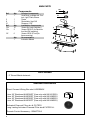 6
6
-
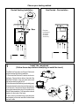 7
7
-
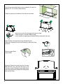 8
8
-
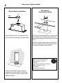 9
9
-
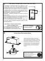 10
10
-
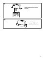 11
11
-
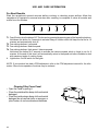 12
12
-
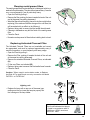 13
13
-
 14
14
-
 15
15
-
 16
16
-
 17
17
-
 18
18
-
 19
19
-
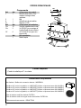 20
20
-
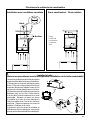 21
21
-
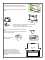 22
22
-
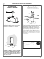 23
23
-
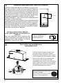 24
24
-
 25
25
-
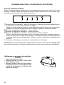 26
26
-
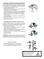 27
27
-
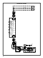 28
28
-
 29
29
-
 30
30
-
 31
31
-
 32
32
-
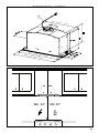 33
33
-
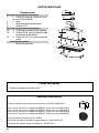 34
34
-
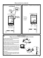 35
35
-
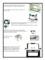 36
36
-
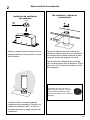 37
37
-
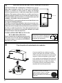 38
38
-
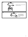 39
39
-
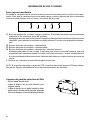 40
40
-
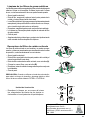 41
41
-
 42
42
-
 43
43
-
 44
44


Faber Inca Lux 21 SSV with VAM Guía de instalación
- Categoría
- Campanas de cocina
- Tipo
- Guía de instalación
- Este manual también es adecuado para
en otros idiomas
Artículos relacionados
-
Faber Classica Plus 30 SSV with VAM Guía de instalación
-
-
-
-
-
-
-
-
-