Yamaha MU90R El manual del propietario
- Categoría
- Sintetizador
- Tipo
- El manual del propietario

IN
PUT
2
VOLUME

FCC INFORMATION (U.S.A)
1. IMPORTANT NOTICE : DO NOT MODIFY THIS UNIT!
This product, when installed as indicated in the instructions contained in this manual, meets FCC requirements. Modifications not expressly
approved by Yamaha may void your authority, granted by the FCC, to use the product.
2. IMPORTANT: When connecting this product to accessories and/or another product use only high quality shielded cables. Cable/s
supplied with this product MUST be used. Follow all installation instructions. Failure to follow instructions could void your FCC
authorization to use this product in the USA.
3. NOTE: This product has been tested and found to comply with the requirements listed in FCC Regulations, Part 15 for Class “B” digital
devices. Compliance with these requirements provides a reasonable level of assurance that your use of this product in a residential
environment will not result in harmful interference with other electronic devices. This equipment generates/uses radio frequencies and, if
not installed and used according to the instructions found in the user’s manual, may cause interference harmful to the operation of other
electronic devices. Compliance with FCC regulations does not guarantee that interference will not occur in all installations. If this product
is found to be the source of interference, which can be determined by turning the unit “OFF” and “ON”, please try to eliminate the problem
by using one of the following measures:
Relocate either this product or the device that is being affected by the interference.
Utilize power outlets that are on different branch (circuit breaker or fuse) circuits or install AC line filter/s.
In the case of radio or TV interference, relocate/reorient the antenna. If the antenna lead-in is 300 ohm ribbon lead, change the lead-in to
co-axial type cable.
If these corrective measures do not produce satisfactory results, please contact the your local retailer authorized to distribute this type of
product. If you can not locate the appropriate retailer, please contact Yamaha Corporation of America, Electronic Service Division, 6600
Orangethorpe Ave, Buena Park, CA 90620
*
The above statements apply ONLY to those products distributed by Yamaha Corporation of America or its subsidiaries.
NEDERLAND / NETHERLAND
• Dit apparaat bevat een lithium batterij voor geheugen back-up.
• This apparatus contains a lithium battery for memory back-up.
• Raadpleeg uw leverancier over de verwijdering van de batterij op
het moment dat u het apparaat ann het einde van de levensduur
afdankt of de volgende Yamaha Service Afdeiing:
Yamaha Music Nederland Service Afdeiing
Kanaalweg 18-G, 3526 KL UTRECHT
Tel. 030-2828425
• For the removal of the battery at the moment of the disposal at the
end of the service life please consult your retailer or Yamaha
Service Center as follows:
Yamaha Music Nederland Service Center
Address : Kanaalweg 18-G, 3526 KL UTRECHT
Tel : 030-2828425
• Gooi de batterij niet weg, maar lever hem in als KCA.
• Do not throw away the battery. Instead, hand it in as small chemical
waste.
ADVARSEL!
Lithiumbatteri—Eksplosionsfare ved fejlagtig håndtering.
Udskiftning må kun ske med batteri af samme fabrikat og type.
Levér det brugte batteri tilbage til leverandoren.
VARNING
Explosionsfara vid felaktigt batteribyte. Använd samma
batterityp eller en ekvivalent typ som rekommenderas av
apparattillverkaren. Kassera använt batteri enligt fabrikantens
instruktion.
VAROITUS
Paristo voi räjähtää, jos se on virheellisesti asennettu. Vaihda
paristo ainoastaan laitevalmistajan suosittelemaan tyyppiin.
Hävitä käytetty paristo valmistajan ohjeiden mukaisesti.

This product utilizes batteries or an external power supply
(adapter). DO NOT connect this product to any power sup-
ply or adapter other than one described in the manual, on
the name plate, or specifically recommended by Yamaha.
WARNING: Do not place this product in a position where
anyone could walk on, trip over, or roll anything over
power or connecting cords of any kind. The use of an
extension cord is not recommended! If you must use an
extension cord, the minimum wire size for a 25' cord (or
less ) is 18 AWG. NOTE: The smaller the AWG number,
the larger the current handling capacity. For longer exten-
sion cords, consult a local electrician.
This Product should be used only with the components
supplied or; a cart, rack, or stand that is recommended by
Yamaha. If a cart, etc., is used, please observe all safety
markings and instructions that accompany the accessory
product.
SPECIFICATIONS SUBJECT TO CHANGE: The in-
formation contained in this manual is believed to be correct
at the time of printing. However, Yamaha reserves the right
to change or modify any of the specifications without no-
tice or obligation to update existing units.
This product, either alone or in combination with an ampli-
fier and headphones or speaker/s, may be capable of produc-
ing sound levels that could cause permanent hearing loss.
DO NOT operate for long periods of time at a high volume
level or at a level that is uncomfortable. If you experience
any hearing loss or ringing in the ears, you should consult
an audiologist. IMPORTANT: The louder the sound, the
shorter the time period before damage occurs.
Some Yamaha products may have benches and/or acces-
sory mounting fixtures that are either supplied with the
product or as optional accessories. Some of these items are
designed to be dealer assembled or installed. Please make
sure that benches are stable and any optional fixtures
(where applicable) are well secured BEFORE using.
Benches supplied by Yamaha are designed for seating only.
No other uses are recommended.
NOTICE: Service charges incurred due to lack of knowl-
edge relating to how a function or effect works (when the
unit is operating as designed) are not covered by the manu-
facturer’s warranty, and are therefore the owners responsi-
bility. Please study this manual carefully and consult your
dealer before requesting service.
ENVIRONMENTAL ISSUES: Yamaha strives to pro-
duce products that are both user safe and environmentally
friendly. We sincerely believe that our products and the
production methods used to produce them, meet these
goals. In keeping with both the letter and the spirit of the
law, we want you to be aware of the following:
Battery Notice: This product MAY contain a small non-
rechargeable battery which (if applicable) is soldered in
place. The average life span of this type of battery is ap-
proximately five years. When replacement becomes neces-
sary, contact a qualified service representative to perform
the replacement.
This Product may also use “household” type batteries.
Some of these may be rechargeable. Make sure that the
battery being charged is a rechargeable type and that the
charger is intended for the battery being charged.
When installing batteries, do not mix old batteries with
new, or with batteries of a different type. Batteries MUST
be installed correctly. Mismatches or incorrect installation
may result in overheating and battery case rupture.
Warning: Do not attempt to disassemble, or incinerate any
battery. Keep all batteries away from children. Dispose of
used batteries promptly and as regulated by the laws in
your area.
Note: Check with any retailer of household type batteries
in your area for battery disposal information.
Disposal Notice: Should this Product become damaged
beyond repair, or for some reason its useful life is consid-
ered to be at an end, please observe all local, state, and
federal regulations that relate to the disposal of products
that contain lead, batteries, plastics, etc. If your dealer is
unable to assist you, Please contact Yamaha directly.
NAME PLATE LOCATION: The name Plate is located
on the top of the product. The model number, serial
number, power requirements, etc., are located on this plate.
You should record the model number, serial number, and
the date of purchase in the spaces provided below and
retain this manual as a permanent record of your purchase.
Model
Serial No.
Purchase Date
SPECIAL MESSAGE SECTION
92-BP
PLEASE KEEP THIS MANUAL

ii
WELCOME TO THE MU90R
Welcome to the MU90R
Congratulations and thank you for purchasing the Yamaha MU90R Tone
Generator!
The MU90R is an advanced tone generator providing 779 high-quality
Voices, full General MIDI compatibility — including Yamaha’s new XG-
MIDI (Extended General MIDI) — plus flexible computer interfacing
in a rack-mount unit.
With the convenient built-in host computer interface and MIDI ter-
minals, the MU90R is ideal for any computer music system — from con-
nection to a simple laptop to integration in a complete MIDI studio. With
its large LCD and the intuitive graphic controls on the display, the MU90R
is remarkably easy to use.
The MU90R also features completely independent dual MIDI inputs,
32 Part multi-timbral capacity and full 64-note polyphony for playback
of even the most sophisticated song data. A special Performance mode
gives you flexible four-Voice operation, for live performance applications.
Built-in digital multi-effects give you enormous versatility in “sweeten-
ing” the sound. Plus, the convenient A/D inputs allow you to connect a mi-
crophone, electric guitar or other instrument, and mix those signals with the
MU90R’s Voices. What’s more, the MU90R provides a host of comprehen-
sive, yet easy-to-use editing tools for getting just the sound you need.

iv
TABLE OF CONTENTS
Table of Contents
Welcome to the MU90R .........................................................................................................ii
Unpacking ..............................................................................................................................iii
Table of Contents................................................................................................................... iv
How to Use This Manual ..................................................................................................... vii
Precautions...........................................................................................................................viii
The Controls of the MU90R .................................................................................................. 1
Front Panel .................................................................................................................... 1
Rear Panel ..................................................................................................................... 3
The MU90R — What It Is and What It Can Do ................................................................. 4
What It Is…....................................................................................................................... 4
About General MIDI..................................................................................................... 4
What It Can Do…............................................................................................................. 5
Using With MIDI Keyboard ......................................................................................... 5
Using With a Computer or Sequencer .......................................................................... 5
About the Modes of the MU90R...................................................................................... 6
Play Modes and the Part Controls................................................................................. 6
Utility Mode................................................................................................................ 11
Part Edit Mode ............................................................................................................ 11
GUIDED TOUR
Setting Up Your MU90R ................................................................................................ 14
What You’ll Need.................................................................................................. 14
Making the Connections ....................................................................................... 14
Powering Up and Playing the Demo Song.................................................................... 16
Powering Up ............................................................................................................... 16
Playing the Demo Song .............................................................................................. 17
Playing Your MU90R with a MIDI Keyboard ............................................................. 18
Selecting Voices ............................................................................................................... 19
Changing the Voice Bank............................................................................................ 20
Selecting Voices From Your MIDI Keyboard ............................................................. 21
Changing Some of the Settings — Part Controls ........................................................ 22
Selecting Another Part and Changing its MIDI Channel............................................ 22
Changing the Volume and Pan Settings of a Part ....................................................... 24
Using Mute/Solo.............................................................................................................. 25
Using the A/D Input........................................................................................................ 26
Setting Up the MU90R in Your Music System............................................................. 29
Connecting With a Computer ..................................................................................... 29
Macintosh .............................................................................................................. 29
IBM PC/AT and Clones ........................................................................................ 30
Connecting to Other MIDI Devices............................................................................ 31
Using the MU90R with a MIDI Data Storage Device ................................................. 33
Data Flow Block Diagram.............................................................................................. 34
MIDI/Computer Connecting Cables............................................................................. 35

TABLE OF CONTENTS
v
GUIDED TOUR
REFERENCE
APPENDIX
REFERENCE
Multi Mode...................................................................................................................... 38
Multi Play Mode ......................................................................................................... 39
Play Displays .............................................................................................................. 39
Part Controls ............................................................................................................... 40
Single Part Control...................................................................................................... 41
Selecting Single Part Control ................................................................................ 41
Editing in Single Part ............................................................................................ 41
All Part Control........................................................................................................... 46
Editing in All Part.................................................................................................. 46
Multi Edit Mode.......................................................................................................... 49
Filter ...................................................................................................................... 49
EG (Envelope Generator)...................................................................................... 52
EQ (Equalizer) ...................................................................................................... 57
Vibrato ................................................................................................................... 59
Others .................................................................................................................... 61
Drum Setup Controls............................................................................................. 73
Calling Up the Drum Setup Menu................................................................... 73
Drum Setup Parameters ................................................................................... 75
Performance Mode ......................................................................................................... 80
Performance Play Mode.............................................................................................. 80
Selecting a Performance and its Individual Parts.................................................. 81
Performance Part Control ........................................................................................... 83
Single Part ............................................................................................................. 83
All Part .................................................................................................................. 86
Performance Edit Mode .............................................................................................. 89
Common ................................................................................................................ 89
Part ........................................................................................................................ 93
Filter ...................................................................................................................... 94
EG ......................................................................................................................... 94
EQ ......................................................................................................................... 94
Vibrato ................................................................................................................... 95
Others .................................................................................................................... 95
Copy and Store Operations ......................................................................................... 97
Copy ...................................................................................................................... 97
Store ...................................................................................................................... 98
Recall Function ................................................................................................... 100
Effect Edit Mode........................................................................................................... 101
Reverb (REV) ........................................................................................................... 101
Chorus ....................................................................................................................... 103
Variation.................................................................................................................... 104
Insertion 1, 2 ............................................................................................................. 106
About the Effect Connections — System and Insertion ........................................... 109
Equalizer (EQ) Edit...................................................................................................... 112
Utility Mode .................................................................................................................. 114
System Functions ...................................................................................................... 114

vi
TABLE OF CONTENTS
Dump Out Functions................................................................................................. 119
Saving and Restoring Data via MIDI.................................................................. 119
Saving and Restoring Data via TO HOST .......................................................... 119
Initialize Functions ................................................................................................... 122
Demo Song Play (DEMO) ........................................................................................ 125
Sound Module Mode (MODE) ................................................................................. 126
Show Control Change ............................................................................................... 127
Show Exclusive......................................................................................................... 128
About Cable Messages ........................................................................................ 129
APPENDIX
XG .................................................................................................................................. 132
Chapter 0: Format Overview .................................................................................... 132
Chapter 1: MIDI Specifications ................................................................................ 135
Troubleshooting ............................................................................................................ 147
Error Messages ............................................................................................................. 148
Specifications................................................................................................................. 149
Glossary ......................................................................................................................... 151
Index .............................................................................................................................. 153

HOW TO USE THIS MANUAL
vii
How to Use This Manual
You are probably eager to try out your new MU90R Tone Generator right
away and hear what it can do, rather than have to read through a lot of in-
structions before you can even get a sound out of it.
However, to get the most out of your MU90R, we strongly suggest that
you read the following sections in the order given:
1) Precautions
This gives you important information on how to care for your new
MU90R, how to avoid damaging, and how to ensure long-term, reli-
able operation.
2) The Controls of the MU90R
This section introduces you to the panel controls and connectors.
3) The MU90R — What It Is and What It Can Do
This briefly provides an overview of the functions and features of the
MU90R and offers some important hints on how you can use it effec-
tively.
4) Guided Tour
This very important section gets you started using your new MU90R. It
helps you set up the instrument, play it, and use some of the more im-
portant functions and features. The hands-on experience you gain in
this section will help you navigate through the other sections of the
manual.
5) Setting Up the MU90R in Your Music System;
Using the MU90R with a Computer
These sections (within the Guided Tour) provide all you need to know
to effectively integrate the MU90R into your present computer music
system.
6) Reference
Once you’re familiar with everything above, lightly go over this com-
prehensive guide to all editing functions. You won’t need (or want) to
read everything at once, but it is there for you to refer to when you need
information about a certain feature or function.
7) Appendix
Finally, use the sections in the Appendix as necessary. For example, the
Index will come in handy when you need to quickly find information
on a specific topic. Other sections, such as the Glossary, Trouble-
shooting and Error Messages provide additional useful information.

viii
• Use only the stand/rack specified for the instrument. When attaching the
stand or rack, use the provided screws only. Failure to do so could cause
damage to the internal components or result in the instrument falling over.
• Do not operate the instrument for a long period of time at a high or
uncomfortable volume level, since this can cause permanent hearing loss.
If you experience any hearing loss or ringing in the ears, consult a
physician.
■REPLACING THE BACKUP BATTERY
• This instrument contains a non rechargeable internal backup battery which
permits internal data to remain stored even when the power is off. When
the backup battery needs replacing, the message “Battery Low!” will display
in the display. When this happens, immediately back up your data (using
an external device such as the floppy disk-based Yamaha MIDI Data Filer
MDF2), then have qualified Yamaha service personnel replace the backup
battery.
•Do not attempt to replace the backup battery yourself, in order to prevent
the possible serious hazards. Always have qualified Yamaha service
personnel replace the backup battery.
• Never place the backup battery in a location that a child can reach, since
a child might accidentally swallow the battery. If this should happen,
consult a physician immediately.
■SAVING USER DATA
• Save all data to an external device such as the Yamaha MIDI Data Filer
MDF2, in order to help prevent the loss of important data due to a
malfunction or user operating error.
Yamaha cannot be held responsible for damage caused by improper
use or modifications to the instrument, or data that is lost or destroyed.
Always turn the power off when the instrument is not in use.
PRECAUTIONS
PLEASE READ CAREFULLY BEFORE PROCEEDING
* Please keep these precautions in a safe place for future reference.
WARNING
Always follow the basic precautions listed below to avoid the possibility of serious injury or even death from electrical
shock, short-circuiting, damages, fire or other hazards. These precautions include, but are not limited to, the following:
• Do not open the instrument or attempt to disassemble the internal parts or
modify them in any way. The instrument contains no user-serviceable
parts. If it should appear to be malfunctioning, discontinue use immediately
and have it inspected by qualified Yamaha service personnel.
• Do not expose the instrument to rain, use it near water or in damp or wet
conditions, or place containers on it containing liquids which might spill
into any openings.
• If the AC adaptor cord or plug becomes frayed or damaged, or if there is a
sudden loss of sound during use of the instrument, or if any unusual
smells or smoke should appear to be caused by it, immediately turn off
the power switch, disconnect the adaptor plug from the outlet, and have
the instrument inspected by qualified Yamaha service personnel.
• Use the specified adaptor (PA-3B) only. Using the wrong adaptor can
result in damage to the instrument or overheating.
• Before cleaning the instrument, always remove the electric plug from the
outlet. Never insert or remove an electric plug with wet hands.
• Check the electric plug periodically and remove any dirt or dust which
may have accumulated on it.
CAUTION
Always follow the basic precautions listed below to avoid the possibility of physical injury to you or others, or damage
to the instrument or other property. These precautions include, but are not limited to, the following:
• Do not place the AC adaptor cord near heat sources such as heaters or
radiators, and do not excessively bend or otherwise damage the cord,
place heavy objects on it, or place it in a position where anyone could
walk on, trip over, or roll anything over it.
• When removing the electric plug from an outlet, always hold the plug
itself and not the cord.
• Do not connect the instrument to an electrical outlet using a multiple-
connector. Doing so can result in lower sound quality, or possibly cause
overheating in the outlet.
• Remove the adaptor plug from the outlet when the instrument is not to be
used for extended periods of time, or during electrical storms.
• Before connecting the instrument to other electronic components, turn off
the power for all components. Before turning the power on or off for all
components, set all volume levels to minimum.
• Do not expose the instrument to excessive dust or vibrations, or extreme
cold or heat (such as in direct sunlight, near a heater, or in a car during
the day) to prevent the possibility of panel disfiguration or damage to the
internal components.
•Do not use the instrument near other electrical products such as televisions,
radios, or speakers, since this might cause interference which can affect
proper operation of the other products.
• Do not place the instrument in an unstable position where it might
accidentally fall over.
• Before moving the instrument, remove all connected adaptor and other
cables.
• When cleaning the instrument, use a soft, dry cloth. Do not use paint
thinners, solvents, cleaning fluids, or chemical-impregnated wiping cloths.
Also, do not place vinyl or plastic objects on the instrument, since this
might discolor the panel or keyboard.
• Do not rest your weight on, or place heavy objects on the instrument, and
do not use excessive force on the buttons, switches or connectors.

THE CONTROLS OF THE MU90R
1
The Controls of the MU90R
Front Panel
1 PHONES jack
For connection to a set of stereo headphones (1/4”).
2 VOLUME control
Turning this adjusts the overall volume of the MU90R.
3 A/D INPUT 1, 2 jacks
For connection of a microphone, electric guitar or other electronic instruments
(mono 1/4” plugs).
4 A/D INPUT level control
For control of the level of the A/D inputs.
5 PLAY button
For entering the Play mode and switching among the different Play displays.
(See page 39.)
6 UTIL (UTILITY) button
For entering the Utility mode. (See page 114.)
7 MODE button
For entering the Sound Module mode. (See page 126.)
8 EDIT button
For entering the Edit mode. (See pages 49 and 89.)
9 EFFECT button
For entering the Effect Edit mode. (See page 101.)
10 EQ button
For entering the EQ Edit mode. (See page 112.)
1
2
3
4
58
6
7
10
9

2
THE CONTROLS OF THE MU90R
11 MUTE/SOLO button
Pressing this alternately mutes or solos the selected Part. (See page 25.)
12 ENTER button
For calling up menu items in the display and for executing certain functions
and operations. Double-clicking this (pressing it twice quickly) calls up the
System Exclusive hexadecimal message for the current function and param-
eter value.
13 EXIT button
For leaving various display pages and returning to previous displays. Also for
canceling certain functions and operations.
14 PART -/+ buttons
For selecting different Parts. In the Effect Edit mode, these can be used to
switch among the different effects. Pressing these together enters and exits
from All Part control. (See page 46.)
15 SELECT </> buttons
For selecting the various menu items, parameters and controls on the display.
16 VALUE -/+ buttons
For changing the value of a selected parameter or control.
17 DATA dial
For adjusting/changing values of the selection function or parameter. Rotate
this clockwise to increase the value.
18 POWER switch
Pressing this turns the power on and off.
11
12
13
16
15
14
17
18

THE CONTROLS OF THE MU90R
3
Rear Panel
1 MIDI THRU, MIDI OUT and MIDI IN A/B terminals
For connection to other MIDI devices, such as a MIDI keyboard, tone genera-
tor, sequencer, or to a computer that has a MIDI interface. MIDI IN A and B
are independent MIDI ports, allowing full 32-channel MIDI input. MIDI OUT
is for data dumps to another MIDI device, while MIDI THRU is for “daisy-
chain” connection of additional MU90Rs or other MIDI instruments. (See
page 14 for more information on MIDI connections.)
2 HOST SELECT switch
For selecting the type of host computer. (See page 29.)
3 TO HOST terminal
For connection to a host computer that does not have a MIDI interface. (See
page 31.)
4 DC IN jack
For connection to the PA-3B AC power adaptor.
5 OUTPUT L, R jacks
For connection to a stereo amplifier/speaker system. When using a mono sys-
tem, connect it to the L/MONO jack.
6 INDIV. OUTPUT 1, 2 jacks
For independent output of selected Parts (1/4”). Parts selected for output
through these jacks are not output through the main OUTPUT or PHONES
jacks. (See pages 72 and 79.)
1
2
56
34

4
THE MU90R — WHAT IT IS AND WHAT IT CAN DO
The MU90R — What It Is and What It Can Do
What It Is…
The MU90R is a fulll-featured and easy-to-use tone generator. It features
full General MIDI Level 1 compatibility with 128 General MIDI Voices
and 9 drum kits. It also provides new XG-MIDI (Extended General MIDI)
compatibility, with a total of 586 Voices and 20 drum kits. The MU90R has
64-note polyphony and is 32-Part multi-timbral. In other words, the
MU90R has 32 different Parts, each with its own Voice, so that up to 32
different Voices can be sounded simultaneously. Since the MU90R features
dual MIDI input ports (A and B), 16 Parts can be played from one MIDI
port and the remaining 16 from the other port.
The MU90R also has a TO HOST terminal for easy interfacing with a
computer, allowing you to play the Voices using your favorite music soft-
ware. This is where the advanced multi-timbral capabilities come in, let-
ting you playing sophisticated arrangements using up to 32 different Voices
at the same time.
The MU90R also features a special Performance mode, in which four
Parts are played simultaneously over a single MIDI channel. Connected to a
MIDI keyboard, this effectively gives you four tone generators in one. The
MU90R gives you 100 factory-programmed Preset Performances plus 100
Internal Performance locations for your own original Performances.
About General MIDI
General MIDI is a new addition to the worldwide MIDI standard. MIDI, as
you know, stands for Musical Instrument Digital Interface, and makes it
possible for various electronic musical instruments and other devices to
“communicate” with each other. For example, by connecting a sequencer
to the MU90R’s MIDI IN terminal, you could play back a song on the
sequencer using the Voices of the MU90R.
So, where does General MIDI fit in all of this? One of the most impor-
tant features of General MIDI is in the standardization of Voices. This
means that a song recorded in the General MIDI format can be played back
on any General MIDI compatible tone generator and sound just as the com-
poser intended. For example, if there is an alto sax solo in the song, it will
be played by an alto sax Voice on the General MIDI tone generator (and
not by a tuba or harpsichord!). Since the MU90R is fully compatible with
General MIDI, you can take advantage of the vast wealth of musical mate-
rial recorded in that format.

THE MU90R — WHAT IT IS AND WHAT IT CAN DO
5
What It Can Do…
Here are a few ideas on how you can use the MU90R. The list below is not
comprehensive, but is meant to be a general guide to the possibilities and
provide a starting point or springboard for your own creative ideas and ex-
plorations.
Using With MIDI Keyboard
Use the MU90R as supplementary tone generator with your MIDI key-
board and play the Voices of both instruments in a layer together. Or, use
the convenient Performance mode, and play four Voices on the MU90R at
once. You can split the four Voices across the keyboard, playing each from
a different register. Or you can create sophisticated velocity splits, in which
a different Voice is heard depending on how strongly you play the key-
board. Or use keyboard and velocity splits together for even greater flex-
ibility.
Using With a Computer or Sequencer
Home Studio Setup
The MU90R integrates instantly and easily into any existing setup. If you
have a MIDI keyboard, computer and sequencing software, the MU90R
with its high-quality Voices and multi-timbral capabilities can expand your
home studio system.
Take It With You
If you have a laptop computer (and sequencing software), simply connect
the MU90R, plug in some headphones and you’ve got a complete, high-
powered music making system that’s exceptionally easy to use. Use it for
composing, arranging, practicing or making/playing demos for your band.
Multimedia
Since it’s compatible with General MIDI, the MU90R is a natural for multi-
media applications. Since the computer interface is built-in to the MU90R,
it hooks up instantly and easily to the computer’s serial port or printer port,
without the need for any other equipment.

6
THE MU90R — WHAT IT IS AND WHAT IT CAN DO
About the Modes of the MU90R
The MU90R has two main operating modes: Multi and Performance. In
Multi mode, the MU90R is a 32-Part multi-timbral tone generator; in Per-
formance mode, the MU90R effectively functions as four tone generators
controlled over a single MIDI channel.
Which mode the MU90R is in depends on the selected Sound Module
mode. If XG, TG300B or C/M are selected, the MU90R automatically sets
itself to the Multi mode. When PFM is selected, the MU90R is in the Per-
formance mode.
The bottom right of the display indicates the currently selected Sound Mod-
ule mode.
Selected Sound Module mode.
Play Modes and the Part Controls
Once the operating mode of the MU90R is set (Multi or Performance),
there are two main ways you can use the MU90R: playing and editing. In
the Play modes, you play the Voices; in the various Edit modes, you change
their settings.
Within the Play modes are the Part controls. These let you make basic set-
tings for the Parts. The Single Part controls allow you to make independent
settings for each Part, while the All Part controls allow you to change the over-
all settings of all Parts. (See pages 41 and 46 for more information.)
Sound Module Mode
XG
TG300B
C/M
Performance

THE MU90R — WHAT IT IS AND WHAT IT CAN DO
7
The MU90R has several different Edit modes, each with various menus and
operations:
Part Edit Mode
Filter
LPF Cutoff Frequency
LPF Resonance
HPF Cutoff Frequency
EG
EG Attack Time
EG Decay Time
EG Release Time
Pitch EG Initial Level
Pitch EG Attack Time
Pitch EG Release Level
Pitch EG Release Time
Play Mode
Part 1 … 32 All Part A/D
Receive Channel Device Number Receive Channel
Bank Number Source Variation
Program Number A/D Source
Volume Master Volume Volume
Expression Master Attenuator Expression
Pan Pan
Reverb Send Reverb Return Reverb Send
Chorus Send Chorus Return Chorus Send
Variation Send Variation Return Variation Send
Note Shift Transpose

8
THE MU90R — WHAT IT IS AND WHAT IT CAN DO
EQ
EQ Low Frequency
EQ Low Gain
EQ High Frequency
EQ High Gain
Vibrato
Vibrato Rate
Vibrato Depth
Vibrato Delay
Others
Detune
Part Mode
Mono/Poly Mode
Portamento Switch
Portamento Time
Element Reserve
Note Limit Low
Note Limit High
Dry Level (VarConnect=SYS)
Velocity Sensitivity Depth
Velocity Sensitivity Offset
Velocity Limit Low
Velocity Limit High
Pitch Bend Control

THE MU90R — WHAT IT IS AND WHAT IT CAN DO
9
Performance Edit Mode
Common
Performance Name
Portamento Switch
Portamento Time
MW LFO Pitch Modulation Depth
MW LFO Filter Modulation Depth
Pitch Bend Control
A/D Part
AC1 Control Change Number
AC1 Filter Control
AC1 Amplitude Control
AC1 LFO Filter Modulation Depth
Part
Filter
LPF Cutoff Frequency
LPF Resonance
HPF Cutoff Frequency
MW LFO Pitch Modulation Depth
AC1 Control Change Number
AC1 Filter Control
AC1 Amplitude Control
Output Select

10
THE MU90R — WHAT IT IS AND WHAT IT CAN DO
EG
EG Attack Time
EG Decay Time
EG Release Time
Pitch EG Initial Level
Pitch EG Attack Time
Pitch EG Release Level
Pitch EG Release Time
EQ
EQ Low Frequency
EQ Low Gain
EQ High Frequency
EQ High Gain
Vibrato
Vibrato Rate
Vibrato Depth
Vibrato Delay
Others
Detune
Mono/Poly Mode
Note Limit Low
Note Limit High
Dry Level (VarConnect=SYS)
Velocity Sensitivity Depth

THE MU90R — WHAT IT IS AND WHAT IT CAN DO
11
Velocity Sensitivity Offset
Velocity Limit Low
Velocity Limit High
Copy
Store
Recall
For more information on each of these modes and their menus, see the re-
spective sections in the Reference section.
Utility Mode
The Utility mode lets you set functions related to the overall operation of
the MU90R, such as Master Tune, display Contrast and reception of cer-
tain MIDI messages that affect the entire instrument. Included also are mis-
cellaneous operations, such as sending bulk data to a data storage device,
initializing of the MU90R settings, and playing the special Demo song.
Part Edit Mode
The Part Edit mode allows you to change certain settings for each indi-
vidual Part, such as those of the Filter, EG (Envelope Generator), and many
other settings. The internal Voices can be sounded during editing, allowing
you to hear the effects of your edits.

12
THE MU90R — WHAT IT IS AND WHAT IT CAN DO
MEMO

G
UIDED
T
OUR
When using your MU90R for the first time, read through this
short section of the manual. It guides you step-by-step in us-
ing many of the basic operations: setting the instrument up,
connecting it properly to other equipment, and — most im-
portantly — playing it.

14
GUIDED TOUR
Setting Up Your MU90R
In this introductory section, you’ll learn how to set up the MU90R for use
with a MIDI keyboard. (Setting up for use with a computer is covered on
page 29.)
What You’ll Need
☛ The MU90R and the included power adaptor.
☛ A MIDI keyboard, electronic piano, or any instrument that can output
MIDI data.
☛ An amplifier/speaker system, preferably stereo. Alternately, you can use
a set of stereo headphones.
☛ Audio connecting cables.
☛ A MIDI cable.
Making the Connections
CAUTION!
Before making any connections, make sure that all equipment to be connected is turned off,
and that the MU90R power adaptor is not connected to an electrical outlet.
Operation
1 Connect one end of the MIDI cable to the MIDI OUT terminal of
the MIDI keyboard and the other to MIDI IN-A of the MU90R (as
shown in the illustration below).
2 Connect the audio cables from the R and L/MONO OUTPUT
jacks of the MU90R to the appropriate inputs on the amplifier
speaker system (as shown in the illustration below). You can also
connect cables to the INDIV. OUTPUT jacks.
If the amplifier has only one input, use the L/MONO jack on
the MU90R. If you are using stereo headphones, connect them
to the front panel PHONES jack.
3 Set the HOST SELECT switch on the MU90R to MIDI.
4
Connect the power adaptor to the DC IN terminal on the MU90R
and plug the adaptor into an appropriate electrical outlet.

GUIDED TOUR
15
CAUTION!
● Do not attempt to use an AC adaptor other than the PA-3B. The use of an incompatible
adaptor may result in irreparable damage to the MU90R, and even pose a serious shock
hazard.
● Be sure to disconnect the power adaptor from the outlet when the MU90R is not in use.
MIDI Keyboard
MIDI OUT
MIDI IN-A
MIDI CABLE
R
Amplifier
Speaker System
PHONES
DC INL/MONO
Power
Adaptor
STOP CONTINUE START
SOUND
OFF
MERGE
ON/OFF 1 2 3 4 5 6 7 8 9 A B C D E F 0
TRANSPOSE
HEXA
DECIMAL
DECIMAL
DC IN
OCTAV E
OCTAVE SHIFT
OCTAV E
RESET
PITCH
ASSIGNABLE
IN MIDI OUT
ENTER
DRUM
NUMBER
NRPN
CONTROLLER
RPN
FIXED
VELOCITY
MIDI
CH
PROGRAM
CHANGE
BANK
SELECT
TEMPO
PROGRAM RESET SYSTEM WHEEL ASSIGNSEQUENCER
POWER ON OFF
SHIFT
GM
ON
XG
ON
MIDI KEYBOARD CBX-K1
CONTROLLER NUMBER LIST
122 COARSE TUNING
(NRPN)
(RPN)
120 PITCH BEND SENSITIVITY
121 FINE TUNING
123 VIBRATO RATE
124 VIBRATO DEPTH
125 VIBRATO DELAY
126 FILTER CUTOFF FREQUENCY
127 FILTER RESONANCE
128 EG ATTACK TIME
129 EG DECAY TIME
130 EG RELEASE TIME
131 DRUM FILTER CUTOFF FREQUENCY
132 DRUM FILTER RESONANCE
133 DRUM EG ATTACK RATE
134 DRUM EG DECAY RATE
135 DRUM PITCH COARSE
136 DRUM PITCH FINE
137 DRUM LEVEL
138 DRUM PAN
139 DRUM REVERB DEPTH
140 DRUM CHORUS DEPTH
141 DRUM VARIATION DEPTH
142 CHANNEL PRESSURE
143 POLYPHONIC KEY PRESSURE
144 MASTER VOLUME
145 MASTER BALANCE
146 MASTER TUNING
147 VELOCITY
148 TEMPO
OTHERS
74 BRIGHTNESS
84 PORTAMENTO CONTROL
91 REVERB DEPTH
92 TREMOLO DEPTH
93 CHORUS DEPTH
94 VARIATION DEPTH
95 PHASER DEPTH
73 ATTACK TIME
1 MODULATION DEPTH
5 PORTAMENTO TIME
6 DATA ENTRY
7 MAIN VOLUME
8 BALANCE CONTROL
10 PANPOT
CONTROL CHANGE
2 BREATH CONTROL
4 FOOT CONTROL
64 HOLD1(DAMPER)
65 PORTAMENTO
66 SOSTENUTO(CHORD HOLD)
67 SOFT PEDAL
69 HOLD2 (FREEZE)
71 HARMONIC CONTENT
72 RELEASE TIME
11 EXPRESSION

16
GUIDED TOUR
Powering Up and Playing the Demo Song
Once you’ve connected everything properly, you’re ready to turn the
MU90R on and start playing it. However, a small word of caution before
you begin: Follow the instructions given below to avoid possible damage
to your equipment and speakers.
Powering Up
Operation
1 If you haven’t done so already, press the POWER switch on the
MU90R.
After the greeting display, the following display will appear:
2 Turn on the power of your MIDI keyboard.
3 Make sure that all volume controls (on the MU90R and the con-
nected amplifier) are turned down. Then, turn on the power of
your amplifier speaker system.
4 Finally, set the volume control on the MU90R to about the mid-
way position and set the volume on the amplifier to a suitable
level.

GUIDED TOUR
17
Playing the Demo Song
Now that you’ve set everything up properly, try playing the built-in Demo
Song. This showcases the high-quality Voices and the AWM2 tone genera-
tion system of the MU90R.
Operation
1 Press the UTIL button.
2 Select “DEMO” with the SELECT w buttons and press the
ENTER button.
3 Press the ENTER button to start the Demo Song.
The Demo Song starts playing immediately and repeats indefinitely
until stopped (in step 4 below). After a while, playback of the indivi-
dual Parts of the song is shown graphically by the “level meter” bars
in the display.
NOTE
During Demo Song playback, all panel controls (except the EXIT button and the VOLUME
control) cannot be used.
4 To stop playback of the song, press the EXIT button.
5 To exit from the Demo Song function, press the EXIT button
again.

18
GUIDED TOUR
Playing Your MU90R With a MIDI Keyboard
Operation
Play some notes on your MIDI keyboard.
If you’ve carefully followed all instructions up to now, one of
the “level meter” bars in the display should move — and you
should be able to hear the sound of the MU90R as you play.
NOTE
If your MIDI keyboard is transmitting on channel 1, the Voice of Part 1 should sound. If it is
transmitting on another channel, another Part’s Voice will sound. For the sake of these intro-
ductory instructions, set your keyboard so that it transmits on channel 1. (Refer to the own-
er’s manual of that instrument if necessary.)
The “level meter” bar indicates the “level” (velocity) of the
incoming MIDI data.
The number under the moving “level meter” indicates the Part number.

GUIDED TOUR
19
Selecting Voices
In this brief section, you’ll learn how to select other Voices. You can do
this directly from the panel of the MU90R or remotely, from your MIDI
keyboard.
Operation
1 First, select a Part. Use the PAR T q buttons to select Part 1.
Press the appropriate button until “01” appears in the PART sec-
tion of the display.
2 Use the SELECT w buttons to move the arrow cursor to the
right side of the instrument icon, as shown below.
3 Use the VALUE q buttons or data dial to change the Voice
number. In the display below, Voice number 26 has been selected.
Voice name.
Voice number (program number).
Instrument icon of current Voice.
MIDI receive channel for current Part.
Part number. (This is selectable only with the PA R T q buttons.)
Solid arrow at Voice number (currently selected).
Arrow cursor (indicates currently selected control).
The arrow is directly above “PGM#” on the panel,
indicating that Program Number is currently selected.
Use these to move arrow cursor.

20
GUIDED TOUR
Play this new Voice from the keyboard. Try selecting other Voices
and play them as well. (For a list of all the available Voices, refer to
the SOUND LIST & MIDI DATA booklet.
HINT
You can rapidly move through the values by holding down one of the VALUE q buttons.
You can move even more rapidly by holding down one button and then pressing and hold-
ing down the other. For example, to rapidly advance (increase) the value, hold down the
VALUE + button and simultaneously press and hold down the VALUE – button.
Changing the Voice Bank
In the current Sound Module mode (XG), several banks of Voices are
available. Each bank can contain up to 128 different Voices.
Operation
1 Use the SELECT w buttons to move the arrow cursor to the
left side of the instrument icon, as shown below.
Solid arrow at Bank number (currently selected).
Bank number.
Use these to move arrow cursor.
Arrow cursor (indicates currently selected control).
The arrow is directly above “BANK” on the panel,
indicating that Bank number is currently selected.

GUIDED TOUR
21
2 Use the VALUE q buttons or data dial to change the Bank
number.
3 Finally, use the SELECT w buttons again to move the arrow
cursor back to the right side of the instrument icon — for Voice
selection.
Selecting Voices From Your MIDI Keyboard
You can also select Voices remotely from the connected MIDI key-
board. Though the actual operation may differ depending on the
keyboard used, the general procedure is the same. (Refer to the
owner’s manual of your instrument for specific instructions.)
Operation
1 Make sure that your keyboard is set up to send Program Change
messages.
2 Use the panel controls to select a program on your keyboard.
Generally, if everything has been set up properly, the Voice number
and name on the MU90R will change, and will be the same number
as the program number you selected on your keyboard.

22
GUIDED TOUR
Changing Some of the Settings — Part Controls
You can make changes to each individual Part by using the Part controls.
These are always displayed in the Play mode, giving you at-a-glance con-
firmation of the various basic settings of the MU90R. Let’s take a look at
the Play display again:
PART MIDI
BANK/PGM#
VOL EXP PAN REV CHO VAR KEY
Each of these settings can be made independently for each of the Parts. For
example, each Part could have a different Volume setting, or a different Pan
setting. Try going through the brief sections below and making some
changes in the Part controls yourself.
Selecting Another Part and Changing its MIDI Channel
Here we’ll select Part 2 and change its MIDI channel to 1, so that it
matches the MIDI channel of Part 1. This allows you to play the Voices of
both Part 1 and Part 2 over MIDI channel 1.
Voice name, bank number and program number
for the selected Part.
Note Shift setting
for the selected
Part.
Chorus Send setting for the
selected Part.
Variation Send setting
for the selected Part.
Pan setting for the selected Part.
Expression setting for the selected Part.
MIDI receive channel for the selected Part.
Volume setting for the selected Part.
Part number.

GUIDED TOUR
23
Operation
1 Use the PAR T q buttons to select Part 2.
Part 2.
2 Use the SELECT w buttons to call up the “Rcv CH” display
below.
Current MIDI Receive Channel.
3 Use the VALUE q buttons or data dial to change the MIDI
Receive Channel to “A01.”
4 Finally, use the SELECT w buttons to move the arrow cursor
back to the instrument icon (so that the Voice name is displayed),
and play the MIDI keyboard again.
Both “level meters” move together.
If both Parts 1 and 2 have been set to MIDI channel 1, both of their “level
meters” should move together as you play. And, if the two Parts are set to dif-
ferent Voices, you should hear two different Voices sound at the same time.
(To change the Voice for a Part, refer back to Selecting Voices above.)

24
GUIDED TOUR
Changing the Volume and Pan Settings of a Part
Now that you’re playing two Voices at the same time, you may want to ad-
just their settings. Here, we’ll change the Volume and Pan settings of one
Part’s Voice.
Operation
1
Use the PAR T q buttons to select the desired Part (Part 1 or 2).
2 Use the SELECT w buttons to call up the “Volume” display
below.
Current Volume setting.
3 Use the VA L U E q buttons or data dial to change the setting,
and play the keyboard as you make changes.
4 Now that you’ve adjusted the Volume balance of the two Voices,
change one of the Part’s Pan setting. Use the SELECT w but-
tons to call up the “Pan” display below.
Current Pan setting.
5 Use the VA L U E q buttons or data dial to change the setting,
and play the keyboard again as you make changes.
If you want, try making changes to some of the other Part controls. The
procedure is the same: 1) Use the PART q buttons to select a Part, 2)
use the SELECT w buttons to choose the desired control, and 3) use
the VALUE q buttons or data dial to change the setting. For more
information on the Part controls, see page 40.

GUIDED TOUR
25
Using Mute/Solo
The MU90R has convenient Mute and Solo functions for selectively mut-
ing or soloing any of the 32 Parts and A/D Parts A1 and A2. This is espe-
cially useful when playing back several Parts from a connected computer
or sequencer. Mute lets you silence one Part to hear how all of the other
Parts sound without it. Solo lets you isolate a single Part, to hear how that
Part sounds by itself.
Mute and Solo are effective tools that help you as you edit the Parts,
since they allow you to better hear how the changes you make affect spe-
cific Voices as well as the overall sound.
Operation
While playing the keyboard (or during playback of a song from a
sequencer), press the MUTE button. Each press cycles through the
three functions: Mute, Solo and Normal operation.
The selected Part is muted, while all other Parts sound normally.
The selected Part is soloed, while all other Parts are muted.
All Parts sound normally.

26
GUIDED TOUR
Using the A/D Input
The MU90R features a special A/D (Analog-to-Digital) Input function that
allows you to connect a microphone, electric guitar or other instrument and
mix in those signals with the MU90R’s Voices. A/D Input is perfect for
singing along with your keyboard performance, since it allows you to blend
the two signals without the need for an external mixer. Or you can use it to
sing or play guitar over backing tracks played from a MIDI sequencer.
There are two A/D Parts — A1 and A2 — and they include several differ-
ent pre-programmed settings that take advantage of the built-in effects of
the MU90R.
The MU90R has two inputs on the front panel. The signals from these
are mixed.
Operation
1 Turn down the A/D INPUT control on the front panel.
2 Connect the microphone, instrument or audio source to the A/D
INPUT jack(s) on the front panel. (Depending on the equipment
you intend to connect, converting adaptors may be necessary.)

GUIDED TOUR
27
3 Use the PA R T q buttons to select Part A1.
4 Use the SELECT w buttons to move the arrow cursor to
PGM#, as shown below, and use the VALUE q buttons or
data dial to select number 002.
5 Move the arrow cursor to BANK (with the SELECT w buttons)
and use the VALUE q buttons or data dial to select the type
of input: Mic, Guitar, Keyboard, Audio, Stereo Keyboard or
Stereo Audio. This determines the gain level of the input. Select
the type corresponding to the input you’ll use.
6 Slowly bring up the A/D INPUT control on the front panel and
play the instrument (or sing into the microphone) until the level
is appropriate.

28
GUIDED TOUR
7 Now, move the arrow cursor back to PGM# (with the SELECT
w buttons) and try selecting some different A/D programs
(with the VALUE q buttons or data dial).
The available programs have been specially programmed to suit
the type of input selected. For example, programs for Mic input
include Karaoke and Vocal; Guitar input programs include Tube,
Stack and Phaser. Explore some of these settings on your own
with a microphone and different instruments.

GUIDED TOUR
29
Setting Up the MU90R in Your Music System
As you learned in the section The MU90R — What It Is and What It
Can Do on page 4, the MU90R can be integrated into a variety of setups. It
would be impossible to cover all connection possibilities in a short manual
as this; however, the section below will help in quickly setting up the
MU90R and using it in your system.
Connecting With a Computer
The MU90R features a built-in host computer interface, allowing you to di-
rectly connect it to your computer — eliminating the need of installing a
special MIDI interface to your computer. The MU90R can be used with the
following computers: Apple Macintosh and IBM PC.
If your computer has a MIDI interface you may want to connect the
MU90R to it, rather than using the host computer interface on the MU90R.
(See the section “Connecting to Other MIDI Devices” on page 31.)
Depending on the computer or interface used, set the HOST SELECT
switch to the appropriate setting: MIDI, PC-1, PC-2 (IBM and clones), or
Mac (Macintosh). For information on the types of cables that can be used
for connection, see the section “MIDI/Computer Connecting Cables” on
page 35.
Macintosh
Follow these instructions if you have an Apple Macintosh not equipped
with an external MIDI interface. Connect the TO HOST terminal on the
MU90R to the Modem or Printer port on the Macintosh.
Modem or
Printer Port
Macintosh

30
GUIDED TOUR
Operation
1 Set the HOST SELECT switch to Mac.
2 Connect the MU90R to the host computer, as shown in the illus-
tration above. Use a standard Macintosh cable (8-pin Mini DIN
on both ends; see page 35).
3 Turn on the the host computer, then the MU90R.
4 Start up your music software, and set up the appropriate options
on the software for operation with the MU90R.
The options you may have to set include:
MIDI Interface Type
gg
gg
g
Standard MIDI Interface
MIDI Time Piece
gg
gg
g
On (for controlling all 32 Parts of the MU90R)
Clock
gg
gg
g
1 MHz
Other options and settings may have to be made as well. Refer to the own-
er’s manual of your particular music software for more information.
IBM PC /AT and Clones
Follow these instructions if you have an IBM PC/AT or compatible computer
not equipped with an external MIDI interface. Connect the TO HOST termi-
nal on the MU90R to one of the computer’s serial ports, COM 1 or COM 2.
IBM PC/AT or Compatible Computer
Serial Port
NOTE
Your music software must be able to recognize the TO HOST connection. Consult your
Yamaha dealer for more details. If your software is not compatible, you can still use the
MU90R by installing a MIDI interface (internal card or external) to the computer.

GUIDED TOUR
31
Operation
1 Set the HOST SELECT switch to PC-2.
2 Connect the MU90R to the host computer, as shown in the illus-
tration above. Use a standard computer cable (8-pin Mini DIN
to 9-pin D-SUB; see page 35).
3 Turn on the the host computer, then the MU90R.
4 Start up your music software, and set up the appropriate options
on the software for operation with the MU90R.
Refer to the owner’s manual of your particular music software for more in-
formation.
Connecting to Other MIDI Devices
The MU90R is equipped with MIDI IN and OUT terminals, allowing you to
use it in any MIDI system. Example uses for the built-in MIDI interface in-
clude:
☛ Connecting to a MIDI keyboard (for playing the sounds of the MU90R
from that keyboard).
☛ Connecting to a computer equipped with a MIDI interface (either in-
ternal or external).
☛ Connecting to a hardware sequencer (such as the Yamaha QY700).
☛ Connecting to a MIDI data storage device (such as the Yamaha MDF2
MIDI Data Filer).

32
GUIDED TOUR
MDF2
MIDI OUT
MIDI IN-A or IN-B
MIDI CABLE
MIDI Keyboard
MIDI OUT
MIDI IN-B
MIDI CABLE
STOP CONTINUE START
SOUND
OFF
MERGE
ON/OFF 1 2 3 4 5 6 7 8 9 A B C D E F 0
TRANSPOSE
HEXA
DECIMAL
DECIMAL
DC IN
OCTAVE
OCTAVE SHIFT
OCTAVE
RESET
PITCH
ASSIGNABLE
IN MIDI OUT
ENTER
DRUM
NUMBER
NRPN
CONTROLLER
RPN
FIXED
VELOCITY
MIDI
CH
PROGRAM
CHANGE
BANK
SELECT
TEMPO
PROGRAM RESET SYSTEM WHEEL ASSIGNSEQUENCER
POWER ON OFF
SHIFT
GM
ON
XG
ON
MIDI KEYBOARD CBX-K1
CONTROLLER NUMBER LIST
122 COARSE TUNING
(NRPN)
(RPN)
120 PITCH BEND SENSITIVITY
121 FINE TUNING
123 VIBRATO RATE
124 VIBRATO DEPTH
125 VIBRATO DELAY
126 FILTER CUTOFF FREQUENCY
127 FILTER RESONANCE
128 EG ATTACK TIME
129 EG DECAY TIME
130 EG RELEASE TIME
131 DRUM FILTER CUTOFF FREQUENCY
132 DRUM FILTER RESONANCE
133 DRUM EG ATTACK RATE
134 DRUM EG DECAY RATE
135 DRUM PITCH COARSE
136 DRUM PITCH FINE
137 DRUM LEVEL
138 DRUM PAN
139 DRUM REVERB DEPTH
140 DRUM CHORUS DEPTH
141 DRUM VARIATION DEPTH
142 CHANNEL PRESSURE
143 POLYPHONIC KEY PRESSURE
144 MASTER VOLUME
145 MASTER BALANCE
146 MASTER TUNING
147 VELOCITY
148 TEMPO
OTHERS
74 BRIGHTNESS
84 PORTAMENTO CONTROL
91 REVERB DEPTH
92 TREMOLO DEPTH
93 CHORUS DEPTH
94 VARIATION DEPTH
95 PHASER DEPTH
73 ATTACK TIME
1 MODULATION DEPTH
5 PORTAMENTO TIME
6 DATA ENTRY
7 MAIN VOLUME
8 BALANCE CONTROL
10 PANPOT
CONTROL CHANGE
2 BREATH CONTROL
4 FOOT CONTROL
64 HOLD1(DAMPER)
65 PORTAMENTO
66 SOSTENUTO(CHORD HOLD)
67 SOFT PEDAL
69 HOLD2 (FREEZE)
71 HARMONIC CONTENT
72 RELEASE TIME
11 EXPRESSION
Operation
1 Set the HOST SELECT switch to MIDI.
2 Connect the MU90R to the appropriate MIDI device, as shown
in the illustrations above. Use a standard MIDI cable (see page
35).
3 Turn on the the connected device, then the MU90R.
4 If you are using a computer, start up your music software, and
set up the appropriate options on the software for operation with
the MU90R.

GUIDED TOUR
33
Using the MU90R with a MIDI Data Storage Device
You can also use the MU90R with a MIDI data storage device, such as the
Yamaha MDF2 MIDI Data Filer. This lets you save or back up whatever
changes you’ve made in the settings of the Utility and Part Edit modes, as
well as changes to the EQ built-in effects and Performances. Then, when
you want to recall those settings, you can transfer the appropriate data from
the storage device.
The MDF2 also allows you to play compatible song data on the
MU90R directly from the MDF2 itself, without the need of a sequencer.
Make sure that the MU90R is properly connected to the data storage
device (via MIDI). Use the Dump Out function (page 119) to send data to
the device. Also refer to the owner’s manual of your data storage device
for specific operating instructions in receiving or sending data.
MDF2
MIDI IN
MIDI OUT
MIDI CABLE

34
GUIDED TOUR
Data Flow Block Diagram
When HOST SELECT switch is set to MIDI (31,250 bps):
Sound
Module
A1~16CH
TO HOST IN-B IN-A OUT THRU
Sound
Module
B1~16CH
When HOST SELECT switch is set to
PC-1/MAC (31,250 bps) or PC-2 (38,400 bps):
Sound
Module
A1~16CH
TO HOST IN-B IN-A OUT THRU
Sound
Module
B1~16CH

GUIDED TOUR
35
MIDI/Computer Connecting Cables
MIDI
Standard MIDI cable. Maximum length 15 meters.
DIN 5-PIN DIN 5-PIN
4
2
5
4
2 (GND)
5
Mac
Apple Macintosh Peripheral cable (M0197). Maximum length 2 meters.
MINI DIN
8-PIN
MINI DIN
8-PIN
1
2
3
2 (HSK i)
1 (HSK o)
5 (RxD –)
4 4 (GND)
5 3 (TxD –)
6 8 (RxD +)
7 7 (GP i)
8 6 (TxD +)
PC-1
8-pin MINI DIN to D-SUB 25-pin cable. If your PC-1 type computer has a
9-pin serial port, use the PC-2 type cable. Maximum length 1.8 meters.
MINI DIN
8-PIN
D-SUB
25-PIN
1
2
3
5 (CTS)
4 (RTS)
3 (RxD)
4 7 (GND)
8
5 2 (TxD)
PC-2
8-pin MINI DIN to D-SUB 9-pin cable. Maximum length 1.8 meters.
MINI DIN
8-PIN
D-SUB
9-PIN
1
2
3
8 (CTS)
7 (RTS)
2 (RxD)
4 5 (GND)
8
5 3 (TxD)
This concludes your basic tour of the important functions of the MU90R. To find out
more about how to best use your MU90R, look through the Reference section that fol-
lows and try out some of the functions and operations that interest you.

MEMO

R
EFERENCE
The Reference section of this manual covers in detail all of
the functions of the MU90R. Refer to it when you need in-
formation about a specific function, feature or operation.

38
MULTI MODE
To set the Multi mode:
1 Press the MODE button.
2 Use theg SELECT w buttons to select the desired Multi mode:
XG, TG300B or C/M.
3 Press the EXIT button or the PLAY button to return to the Play
display.
The currently selected mode setting is shown by the arrow at the bottom
right of the display.
XG
TG300B
C/M
PERFORMANCE
Indicates currently selected mode.
Multi Mode
In the Multi mode, the MU90R performs as a multi-timbral tone generator
capable of playing up to 32 Parts simultaneously, over 32 MIDI channels.
Normally, the MU90R should be set to Multi mode when using it with a
sequencer and General MIDI song data. There are three Multi modes: XG,
TG300B and C/M. Each mode provides compatibility with different music soft-
ware and hardware.
XG: This stands for Extended General MIDI and provides the full poten-
tial of the MU90R, giving you access to all 586 Voices.
TG300B: This mode provides compatibility with the GM-B mode of the TG300
Tone Generator.
C/M: This mode provides compatibility with most computer music soft-
ware not supported by the other two Multi modes.
NOTE
When set to the TG300B mode, the MU90R may not be able to play TG300-specific song data with complete
accuracy. However, MIDI data designed for other computer music tone generators is compatible with the
MU90R.

MULTI MODE
39
Multi Play Mode
The Play mode (with the main Play display shown below) is the normal
operating mode of the MU90R. To select the Play mode from any other
mode, press the PLAY button. (The Play mode is also automatically se-
lected when you turn on the MU90R.)
NOTE
Applications that are capable of controlling 32 Parts (e.g., Performer) are set to a clock rate of
1 MHz.
Play Displays
The Play mode has three basic displays, that can be changed according to
your preference. Simply press the PLAY button repeatedly, and the display
alternates as shown below:
1)
Shows full “level meter” indication for the A1 and A2 A/D Parts and Parts
1 — 16. Currently selected parameter (here, Voice number and name) is
displayed at the right side.
Voice number and name for
currently selected Part.
MIDI port (A or B) and channel number for currently selected Part.
Current Part number.
Velocity “level meters” for each Part.

40
MULTI MODE
Parts 17 — 32 can be displayed by selecting one of those Parts with the
PART q buttons. For example, when Part 18 is selected, the changes
as shown below:
2)
Shows half “level meter” indication for the A1 and A2 A/D Parts and all 32
Parts. Currently selected parameter (here, Voice number and name) is dis-
played at top.
3)
Shows full “level meter” indication for the A1 and A2 A/D Parts and all 32
Parts. Currently selected parameter is not displayed.
Part Controls
The Part controls in the Play mode give you tools for adjusting the basic
sound and settings for each Part. The MU90R lets you adjust the various
settings for each Part individually (Single Part control) or together (All Part
control). Each of these types is explained in greater detail below.
NOTE
In the Multi mode, no settings can be permanently saved to the internal memory of the
MU90R. However, you can use the Dump Out function to save Multi settings to a MIDI data
storage device. (See page 119.)

MULTI MODE
41
Single Part Control
The Single Part controls include: MIDI Receive Channel, Bank Number,
Program Number, Volume, Expression, Pan, Reverb Send, Chorus Send,
Variation Send and Note Shift.
Selecting Single Part Control
Single Part control is automatically called up when the MU90R is turned
on. If All Part is selected, simply press both PART q buttons simulta-
neously (or press the EXIT button) to return to Single Part.
Editing in Single Part
Operation
1 Select the Part to be edited by using the PART q buttons.
2 Select the desired control for the selected Part by using the
SELECT w buttons.
3 Change the value of the selected control by using the VALUE
q buttons or data dial.
MIDI Receive Port/Channel
This determines the MIDI IN port (A or B) and the receive channel (1
— 16) for the selected Part.
Graphically indicates current Receive Channel setting.
Settings: A1 — A16, B1 — B16

42
MULTI MODE
Bank Number
This determines the bank number of the selected Part’s Voice. Each
bank contains 128 Voices. (Refer to the SOUND LIST & MIDI DATA
booklet.)
A1/A2 (A/D Input) part:
000 — 003
Normal part:
XG: 000, 001, 003, 006, 008, 012, 014, 016 — 020, 024 —
028, 032 — 043, 045, 064 — 072, 096 — 101, SFX
TG300B: 000 — 011, 016 — 019, 024 — 026, 032, 033, 040, 080,
126, 127
C/M: Fixed (only one bank)
Drum part:
XG: 126, 127
TG300B: 000
C/M: Fixed (only one bank)
For more information on selecting banks, see Display Bank Select
parameter, page 118.
Program (Voice) Number
This determines the Voice for the selected Part. (Refer to the SOUND
LIST & MIDI DATA booklet.)
Range: 001 — 128

MULTI MODE
43
Volume
This determines the Volume setting for the selected Part’s Voice.
Graphically indicates current Volume setting.
Range: 000 — 127
Expression (Expresn)
This determines the Expression setting for the selected Part’s Voice.
Graphically indicates current Expression setting.
Range: 000 — 127
Pan
This determines the stereo position of the selected Part’s Voice. A set-
ting of “Rnd” (Random) randomly assigns the Voice to a pan position.
This is useful when you want to have different Voices sound from dif-
ferent random parts of the stereo image. (The Random setting does not
affect the A/D input Parts.)
Graphically indicates current Pan setting.
Settings: Rnd (Random), L63 — C — R63

44
MULTI MODE
Reverb Send (RevSend)
This determines the level of the selected Part’s Voice that is sent to the
Reverb effect. A value of 000 results in a completely “dry” Voice sound.
Graphically indicates current Reverb Send setting.
Range: 000 — 127
NOTE
Keep in mind that the Reverb effect must be properly enabled and set for this parameter to
work as intended. (See page 101.)
Chorus Send (ChoSend)
This determines the level of the selected Part’s Voice that is sent to the
Chorus effect. A value of 000 results in a completely “dry” Voice sound
(no Chorus effect).
Graphically indicates current Chorus Send setting.
Range: 000 — 127
NOTE
Keep in mind that the Chorus effect must be properly enabled and set for this parameter to
work as intended. (See page 103.)
Variation Send (VarSend)
This determines whether the selected Part’s Voice is sent to the Varia-
tion effect or not. A setting of “off” results in no Variation effect being
applied to the Voice.

MULTI MODE
45
Graphically indicates current Variation Send setting.
Settings: off, on (when Variation Connection is set to INS);
000 — 127 (when Variation Connection is set to SYS)
Note Shift (NoteSft)
This determines the key transposition setting for the Part’s Voice.
Graphically indicates current Note Shift setting.
Range: –24 — +24 semitones

46
MULTI MODE
All Part Control
The All Part controls include: Device Number, Master Volume, Master
Attenuator, Reverb Return, Chorus Return, Variation Return and Transpose.
Keep in mind that these controls affect all Parts equally, and either add
to or subtract from their individual values. For example, if Note Shift on
one Part is set to –12, and Transpose (in All Part) is set to +12, that Part’s
pitch value will actually be 0 or normal.
Selecting All Part Control
To select All Part control, press both PART q buttons simultaneously. (or
press the EXIT button). (“All” appears in the PART section of the display.)
Editing in All Part
Operation
1 Select the desired control for all Parts by using the SELECT
w buttons.
2 Change the value of the selected control by using the VALUE
q buttons or data dial.
Device Number (DevNo.)
Graphically indicates current Device Number setting.
Settings: 1 — 16, all
This determines the Device Number for the MU90R, a kind of MIDI
“identification” number to distinguish between multiple units. For

MULTI MODE
47
example, if you are using more than one MU90R, set a different De-
vice Number for each. This is especially important when using the
data dump features. (See page 119.) If you have only one MU90R,
set this to “all.”
Master Volume (M.Volum)
Graphically indicates current Master Volume setting.
Range: 000 — 127
This determines the overall Volume of the Parts.
Master Attenuator (M.Attn)
Graphically indicates current Master Attenuator setting.
Range: 000 (maximum volume) — 127 (minimum volume)
This determines the level of all Parts, but functions as an attenuator; the
greater the value, the lower the volume. This is useful when you are
playing several songs and want to keep their overall level consistent.
Reverb Return (RevRtn)
Graphically indicates current Reverb Return setting.
Range: 000 — 127
This determines the amount of Reverb return in the overall mix.

48
MULTI MODE
Chorus Return (ChoRtn)
Graphically indicates current Chorus Return setting.
Range: 000 — 127
This determines the amount of Chorus return in the overall mix.
Variation Return (VarRtn)
Graphically indicates current Variation Return setting.
Range: 000 — 127
This determines the amount of Variation return in the overall mix.
Variation Return is only available when the Variation Connection
parameter is set to SYS. (See page 106.)
Transpose (Trans)
Graphically indicates current Transpose setting.
Range: –24 — +24 semitones
This determines the overall Transpose setting of the Parts.

MULTI MODE
49
Multi Edit Mode
The Multi Edit mode features various parameters for controlling the Filter,
the EG (Envelope Generator), the EQ, and Vibrato. It also features a vari-
ety of other miscellaneous controls grouped in the Others parameters.
When a Drum Part is selected, Drum-related parameters are also available.
To enter the Multi Edit mode, press the EDIT button. When a normal
Part is selected, the following menu appears:
When a Drum Part is selected, the following menu appears:
Filter
The MU90R features a digital filter that can be used to change the timbre
of the Voices. The filter is affected (together with the level) by the EG (En-
velope Generator), which allows you to change the timbre over time as
well. (See EG, page 52.)
Part Edit Mode
Filter
LPF Cutoff Frequency
LPF Resonance
HPF Cutoff Frequency

50
MULTI MODE
LPF Cutoff Frequency (LPF Cutoff)
This determines the cutoff frequency of the low pass filter (LPF). The
LPF filters out frequencies higher than the cutoff point and “passes” the
lower frequencies. Lower cutoff values create a deeper, more rounded
tone, while higher values create a brighter tone.
Graphically shows LPF Cutoff Frequency setting for each Part.
Selected Part and MIDI channel
Range: –64 — +63
Frequency
Level
These frequencies are “cut”
or filtered out.
These frequencies are
“passed” or let through.
LPF Cutoff Frequency setting
LPF Resonance (LPF Reso)
This determines the amount of filter resonance or emphasis of the LPF
Cutoff Frequency above. Higher values make the filter effect more pro-
nounced and stronger, creating a resonant peak around the cutoff fre-
quency.
Graphically shows LPF Resonance setting for each Part.
Selected Part and MIDI channel
Range: –64 — +63

MULTI MODE
51
Frequency
Level
Resonance
LPF Cutoff Frequency setting
HPF Cutoff Frequency (HPF Cutoff)
This determines the cutoff frequency of the high pass filter (HPF). The
HPF filters out frequencies lower than the cutoff point and “passes” the
higher frequencies. Lower cutoff values preserve the fundamental and
lower overtones of the sound, while higher values create a thinner,
brighter tone.
Graphically shows HPF Cutoff Frequency setting for each Part.
Selected Part and MIDI channel
Range: –64 — +63
Frequency
Level
These frequencies are
“cut” or filtered out.
HPF Cutoff Frequency setting
These frequencies are
“passed” or let through.

52
MULTI MODE
EG (Envelope Generator)
The EG parameters allow you to shape the sound of a Part’s Voice — or, in
other words, set how the level and timbre of the Voice changes over time.
This section also includes independent Pitch Envelope Generator (PEG) pa-
rameters for controlling how the pitch of a Part’s Voice changes over time.
The relationship of the main EG parameters — Attack, Decay and Re-
lease — are shown in the illustration below. These parameters not only affect
the sound level, but also the timbre (with the Filter parameters; see page 49).
1) Short Attack, Decay, Release times:
Level
Attack Decay Release
Time
Key is releasedKey is pressed
Min.
Max.
Part Edit Mode
EG
EG Attack Time
EG Decay Time
EG Release Time
Pitch EG Initial Level
Pitch EG Attack Time
Pitch EG Release Level
Pitch EG Release Time

MULTI MODE
53
2) Long Attack, Decay, Release times:
Level
Attack Decay Release
Time
Key is releasedKey is pressed
Min.
Max.
Keep in mind that the EG parameters affect each other, and are af-
fected by how long a note is held. For example, if Decay is set to a
low value and the note is held for a long time, you may not be able
to hear changes made to the Release parameter.
EG Attack Time
Graphically shows EG Attack Time setting for each Part.
Selected Part and MIDI channel
Range: –64 — +63
This determines the Attack Time of the EG, or how long it takes for
the sound to reach full volume when a note is played. For the Filter,
this determines how long it takes for the sound to be affected by the
maximum Filter values.
Even though the key is held for the same length of time in both examples,
the sound of the second example slowly reaches full volume and decays
over a longer time. It also sustains longer after the key is released.

54
MULTI MODE
EG Decay Time
Graphically shows EG Decay Time setting for each Part.
Selected Part and MIDI channel
Range: –64 — +63
This determines the Decay Time of the EG, or how rapidly the
sound dies out as a note is held. For the Filter, this determines how
long it takes for the Filter effect to die out.
EG Release Time
Graphically shows EG Release Time setting for each Part.
Selected Part and MIDI channel
Range: –64 — +63
This determines the Release Time of the EG, or how long the sound
sustains after a note is released. For the Filter, this determines how
long the Filter effect continues after a note is released.

MULTI MODE
55
Pitch EG Parameters
The Pitch EG parameters determine how the pitch of a Part’s Voice
changes over time. This lets you produce subtle or pronounced pitch
changes as a note is played.
In the example Pitch EG settings below, a played note is gradu-
ally bent up to its normal pitch, and kept there as the note is held.
When the note is released, the pitch rapidly climbs up.
Normal
Pitch
Time
Key is released
Low
High
NOTE
The Pitch EG parameters may have little or no effect, depending on the particular Voice used
and the settings made to the main EG parameters.
Pitch EG Initial Level (PEGInitLvl)
Graphically shows Pitch EG Initial Level setting for each Part.
Selected Part and MIDI channel
Range: –64 — +63
This determines the initial pitch of the Part’s Voice, when the note is
first played. A setting of 00 corresponds to normal pitch.

56
MULTI MODE
Pitch EG Attack Time (PEGAtakTime)
Graphically shows Pitch EG Attack Time setting for each Part.
Selected Part and MIDI channel
Range: –64 — +63
This determines the Attack Time of the Pitch EG, or how long it
takes for the pitch to return to normal (from the pitch value set in
Initial Level above).
Pitch EG Release Level (PEGReleLvel)
Graphically shows Pitch EG Release Level setting for each Part.
Selected Part and MIDI channel
Range: –64 — +63
This determines the final pitch of the Part’s Voice, or the pitch that
is reached after the note is released. A setting of 00 corresponds to
normal pitch.
NOTE
The Pitch EG Release Level and Time parameters may have no effect if the Voice itself does
not sustain after the note is released. (Short percussive Voices may fall into this category.)
Also make sure that the main EG Release Time is set to an appropriate value so that the sound
sustains.

MULTI MODE
57
Pitch EG Release Time (PEGReleTime)
Graphically shows Pitch EG Release Time setting for each Part.
Selected Part and MIDI channel
Range: –64 — +63
This determines the Release Time of the Pitch EG, or how long it
takes for the pitch to change to the pitch value set in Release Level
above.
EQ (Equalizer)
The EQ parameters let you adjust and set the tonal quality of a Part’s Voice,
such as boosting the bass sound, or making it brighter. This is a two-band
equalizer with wide frequency variation for each band, and is independent
of the overall EQ controls (see page 112).
Part Edit Mode
EQ
EQ Low Frequency
EQ Low Gain
EQ High Frequency
EQ High Gain

58
MULTI MODE
EQ Low Frequency (Low Freq)
This determines the frequency which is boosted or cut (in the Low Gain
parameter below) for each Part.
Graphically shows the Low Frequency setting for each Part.
Selected Part and MIDI channel
Range: 32 Hz — 2.0 kHz
EQ Low Gain
This determines the level of the selected frequency (in Low Freq
above). Positive values boost the level of the selected frequency and
negative values attenuate it.
Graphically shows the Low Gain setting for each Part.
Selected Part and MIDI channel
Range: –64 — +00 — +63
EQ High Frequency (High Freq)
This determines the frequency which is boosted or cut (in the High
Gain parameter below) for each Part.
Graphically shows the High Frequency setting for each Part.
Selected Part and MIDI channel
Range: 500 Hz — 16 kHz

MULTI MODE
59
EQ High Gain
This determines the level of the selected frequency (in High Freq
above). Positive values boost the level of the selected frequency and
negative values attenuate it.
Graphically shows the High Gain setting for each Part.
Selected Part and MIDI channel
Range: –64 — +00 — +63
Vibrato
Vibrato produces a quavering, vibrating sound in the Part’s Voice, by regu-
larly modulating the pitch. You can control the speed and depth of the Vi-
brato, as well as the time it takes before the Vibrato effect is applied.
Vibrato Rate
Graphically shows Vibrato Rate setting for each Part.
Selected Part and MIDI channel
Part Edit Mode
Vibrato
Vibrato Rate
Vibrato Depth
Vibrato Delay

60
MULTI MODE
Range: –64 — +63
This determines the speed of the Vibrato effect. Higher values result
in a faster Vibrato sound.
Vibrato Depth
Graphically shows Vibrato Depth setting for each Part.
Selected Part and MIDI channel
Range: –64 — +63
This determines the depth of the Vibrato effect. Higher values result
in a stronger, more pronounced Vibrato sound.
Vibrato Delay
Graphically shows Vibrato Delay setting for each Part.
Selected Part and MIDI channel
Range: –64 — +63
This determines the delay in the onset of the Vibrato effect. Delay is
effective especially on stringed instrument Voices. For example, vio-
lin players often use delayed vibrato, especially while playing long
notes. The Delay parameter is useful in recreating this effect, pro-
ducing a more natural, lifelike sound. Higher values result in a
longer Delay time.

MULTI MODE
61
Others
The Others section of parameters contains miscellaneous controls, includ-
ing those related to tuning, Part Mode, velocity, portamento, note range,
etc.
Part Edit Mode
Others
Detune
Part Mode
Mono/Poly Mode
Portamento Switch
Portamento Time
Element Reserve
Note Limit Low
Note Limit High
Dry Level (VarConnect=SYS)
Velocity Sensitivity Depth
Velocity Sensitivity Offset
Velocity Limit Low
Velocity Limit High
Pitch Bend Control
MW LFO Pitch Modulation Depth
AC1 Control Change Number
AC1 Filter Control
AC1 Amplitude Control
Output Select

62
MULTI MODE
Detune
Graphically shows Detune setting for each Part.
Selected Part and MIDI channel
Range: –12.8 — +12.7
This determines the fine tuning of the Part’s Voice.
HINT
Detune could be used to slightly detune a Voice compared to the tuning of the rest of the
Voices for a richer sound. It could also be used to detune two different Voices being played
in unison. For example if two different Parts are set to the same MIDI channel (see page 41)
and same Voice, a naturally thick chorusing effect can be obtained by slightly detuning each
Voice in opposite directions here.
Part Mode
Height of bars indicates selected Part Mode setting for each Part.
(A single bar indicates “normal” setting.)
Selected Part and MIDI channel
Settings: normal, drum, drumS1 — S4
(When Sound Module mode is set to C/M, both Parts 10 and 26 are set
to drumS1.)
This determines the mode for the Part. A setting of normal allows selec-
tion of the normal instrument Voices. (See the SOUND LIST & MIDI
DATA booklet.) The drum setting allows selection of the drum kits. (See
the SOUND LIST & MIDI DATA booklet.) The drumS1 — S4 settings
are locations for storing specially programmed drum setups. These setups
can be edited by using the Drum Setup controls in the Multi Edit mode.
(See page 73.) The drum and drumS1 — S4 settings are not available in
the Performance mode (all Parts are fixed to “normal”).

MULTI MODE
63
The Part Mode settings differ depending on the Sound Module mode
selected, as described below.
For XG (Extended General MIDI) mode:
All settings described above are available. When normal is selected,
any of the basic or the extended set of Voices can be used for the Part.
For TG300B mode:
The settings normal and drumS1 — S4 are available; drum cannot be
selected. When normal is selected, either the basic or the extended set
of Voices (for the TG300B mode) can be used for the Part.
For C/M mode:
The Part Mode settings are fixed in this mode and cannot be changed:
Parts 10 and 26 are set to drumS1, and all other Parts are set to nor-
mal. The MIDI Receive Channel setting for Parts 1 and 17 is set to off.
The 128 Voices of C/M Type 1 can be used for Parts 1 — 9 and 17 —
25; the 64 Voices of C/M Type 2 can be used for Parts 11 — 16 and 27
— 32.
For PFM (Performance) mode:
All four Parts are set to normal; none of the drum settings are avail-
able. Any of the basic or the extended set of Voices can be used for
each Part.
NOTE
When two or more different Parts are set to the same editable drum setup (drumS1 — S4),
any edits made to that drum setup automatically affect all those Parts. For example, when
two Parts are set to drumS1, any changes made to drumS1 affect both Parts.
Mono/Poly Mode
Height of bars indicates selected Mono/Poly Mode setting for each Part.
(A single bar indicates “mono” setting, while full height indicates “poly.”)
Selected Part and MIDI channel

64
MULTI MODE
Settings: mono, poly
This determines whether the Part’s Voice is played monophonically
(only one note at a time) or polyphonically (up to 64 notes at a
time). This parameter is not available when the Part Mode is set to
Drum.
Portamento Parameters
Portamento is a function that creates a smooth pitch glide from one
note to another.
Portamento Switch (PortametSw)
This determines whether Portamento is on or off for the Part. (This pa-
rameter is not available for Drum Parts.)
Height of bars indicates selected Portamento Switch setting for each Part.
(A single bar indicates “off” setting, while full height indicates “on.”)
Selected Part and MIDI channel
Settings: off, on
Portamento Time (PortametTm)
This determines the time of the Portamento effect, or how long it takes
to glide the pitch from one note to the next. Higher values result in a
longer pitch glide time. (This parameter is not available for Drum
Parts.)
Graphically shows Portamento Time setting for each Part.
Selected Part and MIDI channel
Range: 000 — 127

MULTI MODE
65
Element Reserve (ElemReserv)
This determines the minimum number of sound elements that are re-
served for the Part. This setting ensures that when the maximum simul-
taneous polyphony of 64 notes (or elements) is exceeded, the selected
Part will still play up to the number of elements set here. For example,
if the Element Reserve of a Part is set to 10, the sounds for that Part
(up to 10 simultaneous notes) will not be cut off, even if the maximum
polyphony is exceeded. The total number of Element Reserve values
for all of the Parts cannot exceed 64.
This parameter is useful when playing back dense song data, and it
ensures that the most important Parts in the song data will play prop-
erly without being cut off.
Graphically shows the Element Reserve setting for each Part.
Selected Part and MIDI channel
Range: 00 — 32
Note Limit Parameters
The Note Limit Low and High parameters allow you to set the range of
notes for a Part’s Voice. Notes outside the range will not be played.
HINT
Note Limit can be used to set up keyboard splits. Set two Parts to the same MIDI channel
(see page 41), but give them Note Limit settings so that one Part is played from the left side of
the keyboard and the other is played from the right.
Note Limit Low (NoteLimitL)
Graphically shows Note Limit Low setting for each Part.
Selected Part and MIDI channel

66
MULTI MODE
Range: C-2 — G8
This determines the lowest responding note for the Part. Notes be-
low this value will not be played.
Note Limit High (NoteLimitH)
Graphically shows Note Limit High setting for each Part.
Selected Part and MIDI channel
Range: C-2 — G8
This determines the highest responding note for the Part. Notes
above this value will not be played.
Dry Level
Range: 000 — 127
This determines the level of the unprocessed sound of the Voice
(sound with no effect processing). This parameter is only available
when the Variation Connection parameter is set to SYS. (See page
106.)
Velocity Sensitivity Depth (VelSensDpt)
Graphically shows Velocity Sensitivity Depth setting for each Part.
Selected Part and MIDI channel

MULTI MODE
67
Range: 000 — 127
This determines the degree to which velocity affects the Part’s Voice.
Higher values make the Voice more sensitive to changes in velocity.
Velocity Sensitivity Offset (VelSensOfs)
Graphically shows Velocity Sensitivity Offset setting for each Part.
Selected Part and MIDI channel
Range: 000 — 127
This determines the volume range over which velocity affects. For
lower values, the velocity affects a volume range from minimum to
medium-loud. For higher values, velocity affects a range from me-
dium-soft to maximum.
Level
127
127
0
at 127
at 64
at 0
Velocity
NOTE
Depending on the Voice used, if Velocity Sensitivity Offset is set to too low of a value, the
Voice may not sound, no matter how strong the velocity.
Velocity Limit Parameters
The Velocity Limit Low and High parameters allow you to set the
effective velocity range for a Part’s Voice. Velocity values outside
the range will not be played. (Velocity is generally the strength at
which notes are played from a MIDI keyboard.)
HINT
Velocity Limit can be used to set up velocity splits. A velocity split allows you to have one Part’s
Voice sound when you play the connected keyboard strongly, and a different Voice sound when
you play softly. Set two Parts to the same MIDI channel (see page 41), but give them different Veloc-
ity Limit settings so that one or the other sounds depending on how strongly you play the keyboard.

68
MULTI MODE
Velocity Limit Low (VelLimitLo)
Graphically shows Velocity Limit Low setting for each Part.
Selected Part and MIDI channel
Range: 000 — 127
This determines the lowest velocity value at which the Part’s Voice
will play. The higher the value, the harder the keyboard must be
played for the Voice to sound.
Velocity Limit High (VelLimitHi)
Graphically shows Velocity Limit High setting for each Part.
Selected Part and MIDI channel
Range: 000 — 127
This determines the highest velocity value at which the Part’s Voice
will play. The lower the value, the less strength needed (in playing
the keyboard) to get maximum volume.
no
sound
no
sound
1 127
VelLimitLo VelLimitHi

MULTI MODE
69
Pitch Bend Control (PitBndCtrl)
Graphically shows Pitch Bend Control setting for each Part.
Selected Part and MIDI channel
Range: –24 — +24 semitones (+/– 2 octaves)
This determines the Pitch Bend range for the Part’s Voice. (Pitch Bend
is usually controlled by a pitch bend wheel on a MIDI keyboard.)
Modulation Wheel — LFO Pitch Modulation Depth
(MW LFOPMod)
Graphically shows LFO Pitch Modulation Depth setting for each Part.
Selected Part and MIDI channel
Range: 000 — 127
This determines how widely the pitch is modulated by the LFO (low
frequency oscillator). This is generally controlled from a modulation
wheel on a MIDI keyboard and produces a vibrato effect. The
higher the value, the deeper the pitch modulation, and hence, the
more pronounced the vibrato effect.

70
MULTI MODE
Assignable Controller 1 Control Change Number (AC1 CC No.)
This determines the which MIDI control change number is assigned to
the Assignable Controller (AC1) for the selected Part. AC1 can be used
to affect the Filter (page 71), volume (Amplitude; page 72), LFO (page
69) or the Variation effect (page 104). Make sure that parameters you
don’t want to be affected by AC1 are properly set to 00.
Graphically shows the AC 1 Control Change Number setting for each Part.
Selected Part and MIDI channel
Range: 00 — 95
HINT
Though this parameter allows you to assign any control change number from 0 to 95, only a
few of these are in common use. The controllers most likely to be encountered include:
01 — Modulation wheel or lever
02 — Breath controller
04 — Foot controller
07 — Volume controller
Some or all of these may be available on your MIDI instrument, and can be used to control
certain functions on the MU90R in real time. Some MIDI instruments allow you to change
the control change number for a particular controller: for example, setting the modulation
wheel (normally 01) to control Volume (07). Refer to the owner’s manual of your particular
instrument for more information.

MULTI MODE
71
Assignable Controller 1 Filter Control (AC1 FilCtrl)
This determines the degree to which Assignable Controller 1 (AC1) af-
fects the Cuttoff Frequency of the Low Pass Filter for each Part. For
maximum effect, this should be set to one of the extreme values, nega-
tive or positive. A setting of 00 results in no control over the Filter,
even when AC1 is operated (or control change data is received). Nega-
tive settings affect the Filter negatively; in other words, when the con-
troller is at the minimum position, control over the Filter is greatest.
(The control number used for AC1 is set in the Assignable Controller 1
Control Change Number parameter above.)
Graphically shows the AC 1 Filter Control setting for each Part.
Selected Part and MIDI channel
Range: –64 — +63
In the illustration below, a foot controller is used
as Assignable Controller 1.
For positive values: For negative values:
Minimum
effect
Maximum
effect
Maximum
effect
Minimum
effect
HINT
Positive and negative values can be most effectively used by setting two different Parts to
opposite settings. In this way, moving the controller (for example, a foot controller) one way
will affect one Part and moving it the opposite way will affect the other Part.

72
MULTI MODE
Assignable Controller 1 Amplitude Control (AC1 AmpCtrl)
This determines the degree to which Assignable Controller 1 (AC1) af-
fects the volume (Amplitude) for each Part. For maximum effect, this
should be set to one of the extreme values, negative or positive. A set-
ting of 00 results in no volume control, even when AC1 is operated (or
control change data is received). Negative settings affect the volume
negatively; in other words, when the controller is at the minimum posi-
tion, control over the volume is greatest. (The control number used for
AC1 is set in the Assignable Controller 1 Control Change Number pa-
rameter above.)
Graphically shows the AC 1 Amplitude Control setting for each Part.
Selected Part and MIDI channel
Range: 64 — +63
NOTE
For more information on using positive and negative values, see the illustration and hint in
Assignable Controller 1 Filter Control (page 71).
Output Select (OutPtSel)
This determines the output configuration for the selected Part. When
set to “stereo,” the Part is output (with effects) through the main OUT-
PUT and PHONES jacks. When set to one of the “ind” (individual) set-
tings, it is output through the INDIV. OUTPUT jacks. In this case, only
Insertion effects can be applied; System effects cannot be applied to the
INDIV. OUTPUT jacks. When set to “ind1+2,” the Part is output in
stereo (1: left, 2: right). Settings of “ind1” and “ind2” output the Part
in mono to the corresponding jack. (Parts output through the INDIV.
OUTPUT jacks cannot be heard through the PHONES jack.)

MULTI MODE
73
Graphically shows the Output Select setting for each Part.
Selected Part and MIDI channel
Settings: stereo, ind1+2, ind1, ind2
NOTE
●
The Output Select Lock parameter (page 116) must be set to “off” in order to change this
setting via MIDI.
●
When the Part Mode parameter (page 62) is set to “drum” or “drum S1 — S4”, this setting
is inactive.
Drum Setup Controls
The Drum Setup controls allow you to make a wide variety of settings for
the drum sounds in a Drum Part. These settings include Pitch controls,
Level, Pan, effect send, filter controls and EG (Envelope Generator),
among others. Moreover, these parameters can be set to completely inde-
pendent values for each of the drum sounds in a Part.
Calling Up the Drum Setup Menu
To call up the Drum Setup menu, select a Part for which a Drum Part has
been assigned. The Drum Setup controls automatically come up in the Edit
mode. For example, if Part 10 is assigned a Drum Part, the Drum Setup
menu will appear in the main Edit menu:

74
MULTI MODE
Use the SELECT w buttons to select “DRUM” in the display, and
press the ENTER button.
Operation
1 Select the desired note number and its assigned drum sound with
the PART q buttons.
For a list of the available sounds and their note assignments, see
the SOUND LIST & MIDI DATA booklet.
HINT
You can also select the desired note number by simply pressing the appropriate key on a
connected MIDI keyboard. This function can be enabled or disabled by using the MUTE/
SOLO button.
2 Select the desired parameter with the SELECT w buttons.
Refer to the descriptions below for details on the individual pa-
rameters.
3 Change the parameter value with the VALUE q buttons or
data dial.
Currently selected parameter name and value.
Currently selected note and assigned drum sound.
Use these to select the note number.
(Can also be selected by pressing appropriate
key on connected MIDI keyboard.)
Use these to change the parameter value.
Use these to select the parameter.

MULTI MODE
75
Drum Setup Parameters
The Drum Setup parameters are only available when the Part Mode has
been set to DrumS1 — S4. (See page 62.)
Pitch Coarse
Range: –64 — +63
This determines the coarse pitch setting of the selected drum sound.
Pitch Fine
Range: –64 — +63
This determines the fine pitch setting of the selected drum sound.
Velocity Pitch Sensitivity (VelPchSens)
This determines the degree to which pitch changes of the selected
drum sound respond to velocity. In other words, you can control
how much the pitch of the sound changes by how hard or soft you
play the keys of a connected keyboard. Positive values raise the
pitch and negative values lower the pitch. A value of 00 results in
no pitch change, whatever velocity is received.
Range: –16 — +16
Level
Range: 000 — 127
This determines the volume of the selected drum sound.
Pan
Settings: Rnd (Random), L63 — C — R63
This determines the stereo position of the selected drum sound. A
setting of “Rnd” (Random) randomly assigns the drum to a pan po-
sition. This is useful when you want to have different drums sound
from different random parts of the stereo image.
Reverb Send (Rev Send)
Range: 000 — 127
This determines the level of the selected drum sound that is sent to
the Reverb effect. A value of 000 results in a completely “dry” drum
sound, no matter how much Reverb is applied to the Drum Part.
NOTE
Keep in mind that the Reverb effect must be properly enabled and set for this parameter to
work as intended. (See page 101.) Also, the parameters Reverb Send in Single Part control
(page 44) and Reverb Return in All Part control (page 47) must be set to appropriate values.

76
MULTI MODE
Chorus Send (Cho Send)
Range: 000 — 127
This determines the level of the selected drum sound that is sent to the
Chorus effect. A value of 000 results in a completely “dry” drum sound,
no matter how much Chorus is applied to the Drum Part.
NOTE
Keep in mind that the Chorus effect must be properly enabled and set for this parameter to
work as intended. (See page 103.) Also, the parameters Chorus Send in Single Part control
(page 44) and Chorus Return in All Part control (page 48) must be set to appropriate values.
Variation Send (Var Send)
This determines the level of the selected drum sound that is sent to the
Variation effect. A setting of off results in a completely “dry” drum
sound, no matter how much Variation is applied to the Drum Part.
Settings: off, on (when Variation Connection is set to INS);
000 — 127 (when Variation Connection is set to SYS)
NOTE
Keep in mind that the Variation effect must be properly enabled and set for this parameter to
work as intended. (See page 104.) Also, the parameters Variation Send in Single Part control
(page 44) and Variation Return in All Part control (page 48) must be set to appropriate values.
LPF Cutoff Frequency (LPF Cutoff)
This determines the cutoff frequency of the low pass filter (LPF) for
the selected drum sound. The LPF filters out frequencies higher than
the cutoff point and “passes” the lower frequencies. Lower cutoff val-
ues create a deeper, more rounded tone, while higher values create a
brighter tone. (For more information, see LPF Cutoff Frequency on
page 50.)
Range: –64 — +63 (XG mode),
000 — 127 (TG300B or C/M mode)
LPF Resonance (LPF Reso)
This determines the amount of filter resonance or emphasis of the LPF
Cutoff Frequency above for the selected drum sound. Higher values
make the filter effect more pronounced and stronger, creating a reso-
nant peak around the cutoff frequency. (For more information, see LPF
Resonance on page 50.)
Range: –64 — +63 (XG mode),
000 — 127 (TG300B or C/M mode)

MULTI MODE
77
Velocity LPF Cutoff Sensitivity (VelLPFSens)
This determines the degree to which the LPF Cutoff Frequency for the
selected drum sound changes in response to velocity. In other words,
you can shift the LPF Cutoff Frequency of the filter up or down (and
thus change the timbre of the sound) depending on how hard or soft
you play the keys of a connected keyboard. Positive values raise the
LPF Cutoff Frequency and negative values lower it. A value of 00 re-
sults in no frequency change, whatever velocity is received.
Range: –16 — +16
HPF Cutoff Frequency (HPF Cutoff)
This determines the cutoff frequency of the high pass filter (HPF) for
the selected drum sound. The HPF filters out frequencies lower than the
cutoff point and “passes” the higher frequencies. Lower cutoff values
preserve the fundamental and lower overtones of the sound, while
higher values create a thinner, brighter tone. (For more information, see
HPF Cutoff Frequency on page 51.)
Range: –64 — +63
EQ Low Frequency (Low Freq)
This determines the frequency which is boosted or cut (in the Low Gain
parameter below) for the selected drum sound.
Range: 32 Hz — 2.0 kHz
EQ Low Gain
This determines the level of the selected frequency (in Low Freq
above). Positive values boost the level of the selected frequency and
negative values attenuate it for the selected drum sound.
Range: –64 — +63
EQ High Frequency (High Freq)
This determines the frequency which is boosted or cut (in the High
Gain parameter below) for the selected drum sound.
Range: 500 Hz — 16 kHz

78
MULTI MODE
EQ High Gain
This determines the level of the selected frequency (in High Freq
above) for the selected drum sound. Positive values boost the level of
the selected frequency and negative values attenuate it.
Range: –64 — +63
EG Attack
Range: –64 — +63 (XG mode),
000 — 127 (TG300B or C/M mode)
This determines the Attack Time of the EG (Envelope Generator),
or how long it takes for the sound of the selected drum sound to
reach full volume when a note is played. (See page 52 for more in-
formation about the EG function; also see illustration below.)
EG Decay 1
Range: –64 — +63 (XG mode),
000 — 127 (TG300B or C/M mode)
This determines the Decay 1 time of the EG, or how rapidly the
sound dies down to the Decay 2 level. (See illustration below.)
Higher values result in a longer Decay time.
EG Decay 2
Range: –64 — +63 (XG mode),
000 — 127 (TG300B or C/M mode)
This determines the Decay 2 time of the EG, or how rapidly the
sound dies out completely. (See illustration below.) Higher values
result in a longer Decay time.
Level
EG Attack
EG Decay 1
EG Decay 2
Time
Alternate Group
Settings: off, 001 — 127
This determines the group assignment of the selected drum sound.
Drums assigned to the same group cannot be sounded simultane-
ously. In other words, if one drum in a group is sounding while a
second in the same group is played, the first drum sound will be cut
off and the second will sound.

MULTI MODE
79
HINT
The main use for this parameter is in creating realistic hi-hat sounds. By assigning an open
hi-hat and a closed hi-hat to the same group, you can “choke” or stop the open hi-hat sound
by simply playing the closed hi-hat — just like pressing the pedal on an actual hi-hat set.
Receive Note On (RcvNoteOn)
Settings: on, off
This determines how the selected drum sound responds to MIDI
Note On messages. Normally, this should be set to on so that the
corresponding drum sound plays when a MIDI Note On message is
received. Set this to off when you want to keep the selected drum
sound from playing.
Receive Note Off
Settings: on, off
This determines how the selected drum sound responds to MIDI
Note Off messages. When this is set to on, the selected sound will
stop in response to the corresponding MIDI Note Off message. An
on setting is good for some sustained sounds (like a whistle), or for
key-controlled cymbal “chokes.” For most drum sounds, however,
this should be set to off so that the drum sound plays back in its en-
tirety (is not cut off).
Output Select (OutPtSel)
This determines the output configuration for the selected drum sound.
When set to “stereo,” the drum sound is output (with effects) through
the main OUTPUT and PHONES jacks. When set to one of the “ind”
(individual) settings, it is output (without effects) through the INDIV.
OUTPUT jacks. When set to “ind1+2,” the drum sound is output in
stereo (1: left, 2: right). Settings of “ind1” and “ind2” output the drum
sound in mono to the corresponding jack. (Drum sounds output
through the INDIV. OUTPUT jacks cannot be heard through the
PHONES jack.)
Settings: stereo, ind1+2, ind1, ind2
NOTE
The Output Select Lock parameter (page 116) must be set to “off” in order to change this
setting.

80
PERFORMANCE MODE
Performance Play Mode
To set the Performance mode and call up Performance Play:
1 Press the MODE button.
2 Use the SELECT w button to select “PFM” (PERFORMANCE).
3 Press the EXIT button or the PLAY button to return to the Play
display.
Indicates Performance mode.
XG
TG300B
C/M
PERFORMANCE
Performance Mode
In the Performance mode, the MU90R performs as a four-Part tone generator,
with all Parts controlled over a single MIDI channel. The Performance mode is
so named because it’s ideally suited to live performance situations. It allows
you to play four different Voices at the same time from your MIDI keyboard —
either in a layer, or in sophisticated keyboard and velocity splits. It also gives
you comprehensive control over each of the four Parts for maximum perform-
ance flexibility. A total of 200 Performances are available: 100 Preset and 100
Internal.
NOTE
Drum Parts are not available in the Performance mode.

PERFORMANCE MODE
81
Selecting a Performance and its Individual Parts
To call up a Preset or Internal Performance and select individual
Parts of that Performance:
1
From the Performance Play mode (see section above), press the PART
q
buttons simultaneously, so that the All Part display is shown.
Indicates All Part display.
NOTE
The display is automatically set to All Part when the Performance Play mode is selected.
2 Use the SELECT w buttons to select the Bank parameter, then
use the VALUE q buttons or data dial to select the desired
bank, Preset (Pre) or Internal (Int).
Preset bank:
Internal bank:
Bottom half of keyboard player icon is shown in reverse
display to indicate Preset Performance bank.
Top half of keyboard player icon is shown in reverse
display to indicate Internal Performance bank.

82
PERFORMANCE MODE
3 Use the SELECT w buttons to select the Program Number pa-
rameter, then use the VALUE q buttons or data dial to select
the desired Performance number.
Performance number
4 From the All Part display, press the PART q buttons simulta-
neously, so that the Single Part display is shown.
Indicates currently selected Part.
5 Select the desired Part by using the PART q buttons.
6 Select the desired Voice bank for the Part by using the SELECT
w buttons to select the Bank parameter, and using the VALUE
q buttons or data dial to change the bank number.
7 Select the desired Voice for the Part by using the SELECT w
buttons to select the Program Number parameter, and using the
VALUE q buttons or data dial to change the Voice number.
To return to the All Part display from the Single Part display, either
press the PART
q
buttons simultaneously, or press the EXIT
button.

PERFORMANCE MODE
83
Performance Part Control
Single Part
Bank Number
Settings:
A1 part: 000 — 003, 018, 019
A2 part: 000 — 003
1 — 4 part: 000, 001, 003, 006, 008, 012, 014, 016 — 020, 024,
025, 027, 028, 032 — 043, 045, 064 — 072, 096 —
101, SFX
This determines the bank number of the selected Part’s Voice. Each
bank contains 128 Voices. (Refer to the SOUND LIST & MIDI
DATA booklet.)
Program (Voice) Number
Range: 001 — 100
This determines the Voice for the selected Part. (Refer to the
SOUND LIST & MIDI DATA booklet.)

84
PERFORMANCE MODE
Volume
Graphically indicates current Volume setting.
Range: 000 — 127
This determines the Volume setting for the selected Part’s Voice.
Pan
Graphically indicates current Pan setting.
Settings: Rnd (Random), L63 — C — R63
This determines the stereo position of the selected Part’s Voice. A
setting of “Rnd” (Random) randomly assigns the Voice to a pan po-
sition. This is useful when you want to have different Voices sound
from different random parts of the stereo image.
Reverb Send (RevSend)
Graphically indicates current Reverb Send setting.
Range: 000 — 127
This determines the level of the selected Part’s Voice that is sent to the
Reverb effect. A value of 000 results in a completely “dry” Voice sound.
NOTE
Keep in mind that the Reverb effect must be properly enabled and set for this parameter to
work as intended. (See page 101.)

PERFORMANCE MODE
85
Chorus Send (ChoSend)
Graphically indicates current Chorus Send setting.
Range: 000 — 127
This determines the level of the selected Part’s Voice that is sent to
the Chorus effect. A value of 000 results in a completely “dry” Voice
sound (no Chorus effect).
NOTE
Keep in mind that the Chorus effect must be properly enabled and set for this parameter to
work as intended. (See page 103.)
Variation Send (VarSend)
Graphically indicates current Variation Send setting.
Settings: off, on (when Variation Connection is set to INS);
000 — 127 (when Variation Connection is set to SYS)
This determines whether the selected Part’s Voice is sent to the Vari-
ation effect or not. A setting of off or 000 results in no Variation ef-
fect being applied to the Voice.
Note Shift (NoteSft)
Graphically indicates current Note Shift setting.
Range: –24 — +24 semitones
This determines the key transposition setting for the Part’s Voice.

86
PERFORMANCE MODE
All Part
System MIDI Channel (Sys CH)
Graphically indicates current System MIDI Channel setting.
Settings: 01 — 16, all
This determines the MIDI receive channel for all Parts of the Per-
formance. When this is set to “all,” the Performance responds over
any incoming MIDI channel.
Performance Bank
Settings: Pre (Preset), Int (Internal)
This determines the bank of Performance programs: Preset or Inter-
nal. Preset Performances are those that have been created and
loaded at the factory; the Internal bank is reserved for user-created
Performances.
Performance Number
Range: 001 — 100
This determines the Performance number.

PERFORMANCE MODE
87
Performance Volume (Pfm Vol)
Graphically indicates current Performance Volume setting.
Range: 000 — 127
This determines the overall Volume of the Performance.
Performance Pan (Pfm Pan)
Graphically indicates current Performance Pan setting.
Range: L63 — C — R63
This determines the overall Pan position of the Performance.
Reverb Return (RevRtn)
Graphically indicates current Reverb Return setting.
Range: 000 — 127
This determines the amount of Reverb return for the Performance in
the overall mix.

88
PERFORMANCE MODE
Chorus Return (ChoRtn)
Graphically indicates current Chorus Return setting.
Range: 000 — 127
This determines the amount of Chorus return for the Performance in
the overall mix.
Variation Return (VarRtn)
Graphically indicates current Variation Return setting.
Range: 000 — 127
This determines the amount of Variation return in the overall mix of
the Performance. Variation Return is only available when the Varia-
tion Connection parameter is set to SYS. (See page 106.)
System Transpose (SysTran)
Graphically indicates current Transpose setting.
Range: –24 — +24 semitones
This determines the overall Transpose setting of the Performance.

PERFORMANCE MODE
89
Performance Edit Mode
The Performance Edit mode features various functions and parameters,
grouped in the following sections: Common (related to the Performance as
a whole), Part (related to each of the four Parts), and the Copy and Store
operations.
To enter the Performance Edit mode, press the EDIT button (from the
Performance Play mode). The following menu appears:
Common
The Common parameters allow you to name a Performance, enable the
A/D Parts for a Performance, and set the control change number for
realtime parameter control.
Performance Name (Perform Name)
This allows you to give a name to your edited Performance.

90
PERFORMANCE MODE
Operation
1 From the Performance Name display, press the ENTER button.
2 Use the SELECT w buttons to select the character position
(flashing character) in the name and use the VALUE q but-
tons or data dial to change the character at that position.
Up to 12 characters can be used for the Performance name.
Available characters include all letters of the alphabet, in both
upper and lower case, numbers from 0 to 9, and a variety of mis-
cellaneous characters.
3 Press the EXIT button to return to the previous display (or press
the PLAY button to return to the Play display).
After creating and naming a Performance, you’ll probably want to
save that Performance for future recall. For instructions on saving a
Performance, refer to the Store operation on page 98.
Flashes to indicate character position.
Performance name
Use these to move among character positions.
Use these to change character at selected position.

PERFORMANCE MODE
91
Portamento Switch (PortamnSw)
Same as the corresponding parameter in the Multi Edit mode. (See page
64.)
Portamento Time (PortamnTm)
Same as the corresponding parameter in the Multi Edit mode. (See page
64.)
Modulation Wheel
— LFO Pitch Modulation Depth (MW LFOPMod)
Same as the corresponding parameter in the Multi Edit mode. (See page
69.)
Modulation Wheel
— LFO Filter Modulation Depth (MW LFOFMod)
This determines how widely the Filter (pages 49 and 94) is modulated
by the LFO (low frequency oscillator). This is generally controlled
from a modulation wheel on a MIDI keyboard, and depending on the
Voice used, it creates a “swoosh” or “wah-wah” filter sweep effect.
Higher values result in deeper filter modulation, creating a more pro-
nounced filter sweep effect.
Graphically shows the LFO Filter Modulation Depth setting.
Range: 000 — 127
Pitch Bend Control (PitBndCtrl)
Same as the corresponding parameter in the Multi Edit mode. (See page
69.)
A/D Part
Height of bars indicates A/D Part setting. (A single bar indicates “off”
setting, while full height indicates “on.”)

92
PERFORMANCE MODE
Settings: off, on
This determines whether A/D Parts are enabled for the Performance
or not. When set to “on,” Parts 3 and 4 are automatically set as A/D
Parts (A1 and A2).
HINT
You can use the MU90R strictly as an effect processor for the A/D input (for example, your
guitar or microphone) by Soloing the appropriate A/D Part (A1 or A2).
Assignable Controller 1 Control Change Number (AC1 CC No.)
Same as the corresponding parameter in the Multi Edit mode (page 70),
with the exception that AC1 in the Performance mode can also control
LFO filter modulation (see Assignable Controller 1 LFO Filter Modu-
lation Depth below).
Assignable Controller 1 Filter Control (AC1 FilCtrl)
Same as the corresponding parameter in the Multi Edit mode. (See page
71.)
Assignable Controller 1 Amplitude Control (AC1 AmpCtrl)
Same as the corresponding parameter in the Multi Edit mode. (See page
72.)
Assignable Controller 1 LFO Filter Modulation Depth
(AC1LFOFMod)
This determines the degree to which Assignable Controller 1 (AC1) af-
fects the LFO modulation of the Filter. This creates a regular and con-
tinuous “wah-wah” or filter sweep effect. The higher the value, the
greater the LFO filter modulation. (The control number used for AC1
is set in the Assignable Controller 1 Control Change Number param-
eter above.)
Graphically shows the AC 1 Filter Modulation Depth setting.
Range: 000 — 127

PERFORMANCE MODE
93
Part
Performance Edit Mode
Part
Filter
LPF Cutoff Frequency
LPF Resonance
HPF Cutoff Frequency
EG
EG Attack Time
EG Decay Time
EG Release Time
Pitch EG Initial Level
Pitch EG Attack Time
Pitch EG Release Level
Pitch EG Release Time
EQ
EQ Low Frequency
EQ Low Gain
EQ High Frequency
EQ High Gain
Vibrato
Vibrato Rate
Vibrato Depth
Vibrato Delay

94
PERFORMANCE MODE
Others
Detune
Mono/Poly Mode
Note Limit Low
Note Limit High
Dry Level (VarConnect=SYS)
Velocity Sensitivity Depth
Velocity Sensitivity Offset
Velocity Limit Low
Velocity Limit High
The Part menu contains the Filter, EG, Vibrato and Others parameters for
the Performance.
Filter
The Filter section of Performance Edit parameters are the same as the cor-
responding parameters in the Multi Edit mode. (See page 49.)
EG
The EG section of Performance Edit parameters are the same as the corre-
sponding parameters in the Multi Edit mode. (See page 52.)
EQ
The EQ parameters let you adjust and set the tonal quality of a Perform-
ance Part’s Voice, such as boosting the bass sound, or making it brighter.
This is a two-band equalizer with wide frequency variation for each band,
and is independent of the overall EQ controls (see page 57).

PERFORMANCE MODE
95
Vibrato
The Vibrato section of Performance Edit parameters are the same as the
corresponding parameters in the Multi Edit mode. (See page 59.)
Others
The Others section of Performance Edit parameters contains miscellaneous
controls, including those related to tuning, velocity, note range, etc. With a
few additional parameters, these are the same as the parameters in the Multi
Edit mode.
NOTE
The Part Edit parameter (available in Multi Edit) is not available in Performance Edit mode.
No Drum Parts can be selected for a Performance.
Detune
Same as the corresponding parameter in the Multi Edit mode. (See
page 62.)
Mono/Poly Mode
Same as the corresponding parameter in the Multi Edit mode. (See
page 63.)
Note Limit Low (NoteLimitL)
Same as the corresponding parameter in the Multi Edit mode. (See
page 65.)
Note Limit High (NoteLimitH)
Same as the corresponding parameter in the Multi Edit mode. (See
page 66.)
Dry Level
Same as the corresponding parameter in the Multi Edit mode. (See
page 66.) This parameter is only available when the Variation Con-
nection parameter is set to SYS. (See page 106.)
Velocity Sensitivity Depth (VelSensDpt)
Same as the corresponding parameter in the Multi Edit mode. (See
page 66.)
Velocity Sensitivity Offset (VelSensOfs)
Same as the corresponding parameter in the Multi Edit mode. (See
page 67.)

96
PERFORMANCE MODE
Velocity Limit Low (VelLimitLo)
Same as the corresponding parameter in the Multi Edit mode. (See
page 68.)
Velocity Limit High (VelLimitHi)
Same as the corresponding parameter in the Multi Edit mode. (See
page 68.)

PERFORMANCE MODE
97
Copy and Store Operations
The Copy and Store operations allow you to save and organize the Per-
formances you’ve created.
Copy
The Copy operation allows you to copy the settings of one Performance
program (Preset or Internal) to another Performance number (Internal
only).
Operation
1 From the Performance Edit menu, use the SELECT w buttons
to select “COPY.” Then, press the ENTER button to call up the
Copy operation.
2 Use the SELECT w buttons to select the desired parameter:
memory location, source number or destination number. (The se-
lected parameter flashes.) Then use the VALUE q buttons or
data dial to change the value.

98
PERFORMANCE MODE
3 Press the ENTER button to actually execute the Copy operation.
An “Executing…” message flashes in the display during the op-
eration. When the data has been copied, the MU90R returns to
the Performance Edit menu.
To cancel the operation without copying, press the EXIT button
(before pressing ENTER).
Store
Once you’ve edited or created a Performance, you can save that new Per-
formance for future recall by using the Store operation. Performances can
be saved to any one of the 100 Internal memory locations. With the excep-
tion of the Receive Channel and Transpose (Note Shift) settings made from
the Play screen, all parameter settings in the Play screen and in the Edit,
Effect and EQ modes are saved to the selected Performance number.
Operation
1 From the Performance Edit menu, use the SELECT w buttons
to select “STORE.” Then, press the ENTER button to call up the
Store operation.
Memory location (P = Preset, I = Internal)
Source Performance number
Destination Performance number
Use these to select desired parameter.
Use these to change value.

PERFORMANCE MODE
99
2 Use the VALUE q buttons or data dial to change the destina-
tion Performance number.
3 Press the ENTER button to actually execute the Store operation.
An “Executing...” message flashes in the display during the op-
eration. When the data has been stored, the MU90R returns to
the Performance Edit menu.
To cancel the operation without saving, press the EXIT button
(before pressing ENTER).
Performance number
Use these to change Performance number.

100
PERFORMANCE MODE
Recall Function
Recall is a convenient function that allows you to recover an accidently de-
leted Performance. For example, if you are editing a Performance and inad-
vertently select a different Performance, the edited Performance would nor-
mally be lost. By using Recall before turning off the MU90R or editing an-
other Performance, you can recover the previously edited Performance data.
To use Recall:
1 Select RECALL in the Performance Edit Mode menu, then press
the ENTER button.
The following display briefly appears:
2 At the “Are you sure?” prompt above, press the ENTER button
again to execute the function.
If no previously edited Performance data exists, the following
display briefly appears, indicating no Performance can be re-
called.

EFFECT EDIT MODE
101
Effect Edit Mode
The MU90R features a built-in multi-effect processor with 6 independent dig-
ital effects: Reverb, Chorus, Variation, Insertion 1/2 and EQ. The first 5 of these
are controlled in the Effect Edit mode.
In this section, only the effect Types and the global parameters common to
all Types are covered. For descriptions and details on the parameters for each
effect Type, refer to the separate SOUND LIST & MIDI DATA booklet.
To enter the Effect Edit mode, press the EFFECT button. The following menu
appears:
Reverb (REV)
Reverb recreates the sounds of various performance environments by add-
ing an ambient wash of delays or reflections. Several different types of
Reverb effects are available to simulate the ambience of different sized
rooms.
Explanations of the Reverb Type and Reverb Pan parameters are given
below. For descriptions and explanations for all other Reverb parameters,
refer to the separate SOUND LIST & MIDI DATA booklet.
Type

102
EFFECT EDIT MODE
Settings: NO EFFECT, HALL 1, HALL 2, ROOM 1, ROOM 2,
ROOM 3, STAGE 1, STAGE 2, PLATE, WHITE ROOM,
TUNNEL, CANYON, BASEMENT
This determines the Reverb Type. Each Reverb Type has different
values for the rest of the Reverb parameters; for example, Basement
has a Reverb Time of 0.6 seconds, while Canyon has a Reverb Time
of 12.0 seconds.
NOTE
When “NO EFFECT” is selected, Reverb is off and none of the other Reverb parameters are
available (with the exception of the Reverb Pan parameter).
HINT
Generally when using Reverb, you can simply select the particular Type needed, and use it
without bothering to adjust the other parameters. If fine tuning of the Reverb sound is neces-
sary, delve into the other parameters as needed.
Reverb Pan (RevPan)
Range: L63 — C — R63
This determines the Pan position of the Reverb sound, or where it
appears in the stereo image.
For details on the parameters for each Reverb Type, refer to the
separate SOUND LIST & MIDI DATA booklet.

EFFECT EDIT MODE
103
Chorus
The Chorus section uses pitch modulation to create a variety of rich, spa-
cious-sounding effects, including Chorus, Flanger, Symphonic and Phaser.
Explanations of the Chorus Type and Chorus Pan parameters are given
below. For descriptions and explanations for all other Chorus parameters,
refer to the separate SOUND LIST & MIDI DATA booklet.
Type
Settings: NO EFFECT; CHORUS 1 — 4; CELESTE 1 — 4;
FLANGER 1 — 3; SYMPHONIC; ENSEMBLE
DETUNE; PHASER 1
This determines the Chorus Type. Depending on the Type selected,
the specific parameters and values may differ.
Chorus 1 and 2 are used to subtly enhance the sound, and generally make it
richer, fatter and warmer. Flanger uses modulation to create an animated,
swirling motion effect, and produces a characteristic metallic sound. Sym-
phonic also subtly enhances the sound by making a single instrument Voice
sound like several. Phaser is similar to Flanger, but with a stronger and
deeper modulation.
NOTE
When NO EFFECT is selected, Chorus is off and none of the other Chorus parameters are
available (with the exception of the Chorus Pan and Send Chorus to Reverb parameters).
Chorus Pan (ChoPan)

104
EFFECT EDIT MODE
Range: L63 — C — R63
This determines the Pan position of the Chorus sound, or where it
appears in the stereo image.
Send Chorus to Reverb (SendCho → Rev)
Range: 000 — 127
This determines the level of the Chorus signal sent to and processed
by the Reverb effect. A setting of 000 results in none of the Chorus-
processed signal going to the Reverb.
HINT
Setting this to a relatively high level gives you a more natural sound, since the Chorus-proc-
essed sound is also being processed by the reverb. More unusual effects can be created by
having a long Reverb and setting this to 0, so that the Chorus sound is dry (no Reverb) and
the original sound is “drenched” in Reverb.
For details on the parameters for each Chorus Type, refer to the separate
SOUND LIST & MIDI DATA booklet.
Variation
The Variation section provides a wealth of additional effects for processing
the Voices of the MU90R. It features some of the same effects found in the
Reverb, Chorus and Insertion sections. This is not mere redundancy; it allows
you to use two types of Reverb, Chorus or other effects on different Voices.
For example, you may want to have the Flanger effect on one Voice and
Phaser on another. Variation also gives you many special effects not found in
the other sections, such as Delay, Gate Reverb, Wah and Pitch Change.
The Variation section of effects can be applied either to a single se-
lected Part or to all Parts, depending on the connection setting: Insertion or
System. (See About the Effect Connections — System and Insertion on
page 106 for more information.)
Explanations of the Variation Type and other common parameters are
given below. For specific descriptions of Variation Types and explanations
for all other Variation parameters, refer to the separate SOUND LIST &
MIDI DATA booklet.

EFFECT EDIT MODE
105
Type
Settings: NO EFFECT; WHITE ROOM; TUNNNEL; CANYON;
BASEMENT; DELAY L,C,R; DELAY L,R; ECHO;
CROSS DELAY; ER 1 — 2; GATE REVERB; RE-
VERSE GATE; KARAOKE 1 — 3; CHORUS 1 — 4;
CELESTE 1 — 4; FLANGER 1 — 3; SYMPHONIC;
ENSEMBLE; DETUNE; AMBIENCE; ROTARY
SPEAKER; 2WAY ROTARY SPEAKER; TREMOLO;
AUTO PAN; PHASER 1 — 2, DISTORTION; COMP+
DISTORTION; OVER DRIVE; AMP SIMULATOR;
3BAND EQ (MONO); 2BAND EQ (STEREO); AUTO
WAH (LFO); AUTO WAH+DIST; AUTO WAH+ODRV;
TOUCH WAH 1; TOUCH WAH+DIST; TOUCH WAH+
ODRV; TOUCH WAH 2; PITCH CHANGE 1 — 2; AU-
RAL EXCITER (R); COMPRESSOR; NOISE GATE;
VOICE CANCEL; THRU
NOTE
When NO EFFECT or THRU is selected for the Type, no Variation effect is applied, and only
the common parameters shown below are available (with the exception of Dry/Wet).
The NO EFFECT setting cancels the Variation effect. When the Variation Connection is set to
SYS (System), the sound can be heard with no effect. When the Variation Connection is set to
INS (Insertion), no sound is output for the Part.
When set to THRU, the sound of the Part (or Parts) is output without any Variation effect.
Generally, when Variation Connection is set to INS (Insertion), you should set the Type to
Thru. When Variation Connection is set to SYS (System), you should set the Type to NO
EFFECT.
Common Parameters (Insertion connection):
Dry/Wet
Range: D63>W — (D=W) — D<W63
Adjusts the level balance of original sound (dry, or D) and processed
sound (wet, or W). A setting of (D=W) results in an equal balance
of dry and wet sound.

106
EFFECT EDIT MODE
Assignable Controller 1 Variation Control (AC1VarCtrl)
Range: 000 — 127
Determines the amount of effect the Assignable Controller has on
the Variation effect.
Common Parameters (System connection):
Variation Pan (VarPan)
Range: L63 — C — R63
Determines the pan position of the Variation effect.
Send Variation to Chorus (SendVar→Cho)
Range: 000 — 127
Determines the amount of Variation effect sound that is sent to the
Chorus effect.
Send Variation to Reverb (SendVar→Rev)
Range: 000 — 127
Determines the amount of Variation effect sound that is sent to the
Reverb effect.
Variation Connection (VarConnect)
Settings: INS (Insertion), SYS (System)
Determines how the Variation effect is connected in the effect chain
of the MU90R. When set to SYS (System), Variation is applied to
all Parts, according to the amount of Variation Send set for each
Part. When set to INS (Insertion), Variation is applied to only the
selected Part, set in Send Variation parameters (see above).
NOTE
The common parameters above are common to nearly all the Variation effect types. (Excep-
tions are described in the separate SOUND LIST & MIDI DATA booklet.
Insertion 1, 2
The Insertion 1 and 2 effects provide additional effects for proces-
sing individual Parts.
Explanations of the Type, Dry/Wet Balance and Part parameters
are given below. For descriptions and explanations for all other pa-
rameters, refer to the separate SOUND LIST & MIDI DATA
booklet.

EFFECT EDIT MODE
107
The Insertion effects are set up for Insertion routing and can be
applied only to a single selected Part. Refer to About the Effect
Connections — System and Insertion on page 106 for more
information.
Type
Settings: THRU; HALL 1 — 2; ROOM 1 — 3; STAGE 1 — 2;
PLATE; DELAY L,C,R; DELAY L,R; ECHO; CROSS
DELAY;
KARAOKE 1 — 3; CHORUS 1 — 4; CELESTE
1 — 4; FLANGER 1 — 3; SYMPHONIC; ENSEMBLE
DETUNE; ROTARY SPEAKER; TREMOLO; AUTO
PAN; PHASER 1; DISTORTION; OVER DRIVE; AMP
SIMULATOR; 3BAND EQ (MONO); 2BAND EQ
(STEREO); AUTO WAH (LFO); TOUCH WAH 1 — 2,
AURAL EXCITER (R), COMPRESSOR; NOISE GATE
NOTE
When Thru is selected, no effect is applied, and none of the parameters are available (with
the exception of the Part parameter).
Dry/Wet Balance
Range: D63>W — (D=W) — D<W63
This determines the balance between the direct, unprocessed signal
(dry) and the processed sound (wet). Use this parameter together
with the Output Level parameter above to obtain the desired overall
sound.
Assignable Controller 1 Insertion 1/2 Control (AC1INS1/2Ctrl)
This determines the degree to which Assignable Controller 1 (AC1)
affects the MIDI-controllable parametes of the Insertion effects.
Each of the Insertion effect types have one parameter which can be
controlled by the AC1. (For details, see the “Effect Parameter List”
of the “SOUND LIST & MIDI DATA” booklet.) This parameter is
not available in the performance mode.

108
EFFECT EDIT MODE
Range: –64 — +63
Insertion 1, 2 Part (INS 1, 2 Part)
Range: Part 1 — 32, AD 1, AD 2, off
This determines the Part to which the Insertion effect is applied.
Insertion can be applied to only one Part at a time.

EFFECT EDIT MODE
109
About the Effect Connections —
System and Insertion
The multi-effects of the MU90R provide not only a wide range of
sound processing controls, but also a flexible system for connecting
them. Unlike simple effect routing schemes on conventional sound
modules that process all voices with the same effects, the MU90R
allows you to put independent, special effects on one or two Parts,
as well as use overall effects for processing all 34 Parts together. For
example, you can have a Distortion effect on a guitar Part and a ro-
tary speaker effect for an organ Part, yet still use ambient effects
such as Reverb and Chorus for processing the overall mix.
All the effect sections are connected or routed in one of two ways: System
or Insertion. System applies the selected effect to all 34 Parts, while Inser-
tion applies the selected effect to one specific Part. Reverb, Chorus, and EQ
are all System effects, and Insertion 1 and 2 are Insertion effects. The Vari-
ation effect section, on the other hand, can be configured for either System
or Insertion routing. (This is done from the Variation Connection param-
eter; see page 106.) Since System and Insertion are part of the XG MIDI
(Extended General MIDI) format, you can create and play back song data
using the same flexible effect routings on any tone generator or sound mod-
ule having the XG mark.
NOTE
The Variation Connection default setting is Insertion.
The illustrations and explanations below cover the System and Insertion
connections in greater detail.

110
EFFECT EDIT MODE
NOTES
●
The Parts to which Insertion 1, 2 are applied is determined by the Part parameter in the Insertion section (page 106).
●
Even though the System routing applies the selected effect to all Parts, you can control how much the Reverb, Chorus and Variat
ion effects are applied to any indi-
vidual Part (with the Reverb Send, Chorus Send and Variation Send parameters in the Single Part controls; see page 44). For the effects to be properly heard, the
Reverb Return, Chorus Return and Variation Return parameters in the All Parts controls must also be set to appropriate values (see pages 47 — 48).
●
The stereo position of the effects is controlled by the Reverb Pan, Chorus Pan and Variation Pan parameters; see pages 102, 103, 106.
●
You can set Reverb, Chorus and Variation to be routed in parallel or in serial, and you can determine the amount of Variation e
ffect that is sent to Chorus and Reverb, as
well as the amount of Chorus that is sent to Reverb. This is done with the Send Variation to Chorus (page 106), Send Variation to Reverb (page 106), and Send Chorus to
Reverb (page 104) parameters. When these are all set to 0, all three effects are in parallel routing. Higher values for each provide varying degrees of serial routing.
When Variation is set to System:
INS2
rev send
cho send
var send
insertion 2 on/off
dry level
VARIATION
REVERB
reverb return
chorus return
variation return
send chorus to reverb
send variation to chorus
send variation to reverb
DRY LINE
PAN
PAN
PAN
reverb pan
chorus pan
variation pan
OUT
Thick line indicates stereo signal.
EQ
Insertion 2 can be
applied to only one
Part at a time.
CHORUS
VARIATION CONNECTION = SYSTEM
insertion 2 part
INS2
rev send
cho send
var send
insertion 2 on/off
dry level
INS2
rev send
cho send
var send
insertion 2 on/off
dry level
INS2
rev send
cho send
var send
insertion 2 on/off
dry level
INS1
insertion 1 on/off
part A1
Insertion 1 can be
applied to only one
Part at a time.
insertion 1 part
INS1
insertion 1 on/off
INS1
insertion 1 on/off
INS1
insertion 1 on/off
part A2
part 1
part 32

EFFECT EDIT MODE
111
When Variation is set to Insertion:
NOTES
●
As with System above, the Parts to which Insertion 1, 2 are applied is determined by the Part parameter in the Insertion section (page 106). Also, the Part to which
Variation is applied is determined by the Variation Send control in the Single Part controls (page 44).
●
As with System above, the effects cannot be properly heard unless the Reverb Send, Chorus Send and Variation Send parameters in the Single Part controls (page 44)
and the Reverb Return and Chorus Return parameters in the All Parts controls are set to appropriate values.
●
The stereo position of the effects is controlled by the Reverb Pan and Chorus Pan parameters. (See pages 102, 103.)
●
You can set Reverb and Chorus to be routed in parallel or in serial, and you can determine the amount of Chorus that is sent to
Reverb. This is done with the
Send
Chorus to Reverb parameter (see page 104). When this is set to 0, Reverb and Chorus are in parallel routing. Higher values for each provide varying degrees of serial
routing.
INS2
rev send
cho send
insertion 2 on/off
VAR
variation on/off
dry
variation part
REVERB
reverb return
chorus return
send chorus to reverb
DRY LINE
PAN
PAN
reverb pan
chorus pan
OUT
Thick line indicates stereo signal.
EQ
Insertion 2 can be
applied to only one
Part at a time.
CHORUS
Variation can be
applied to only one
Part at a time.
VARIATION CONNECTION = INSERTION
INS2
rev send
cho send
insertion 2 on/off
VAR
variation on/off
dry
INS2
rev send
cho send
insertion 2 on/off
VAR
variation on/off
dry
INS2
rev send
cho send
insertion 2 on/off
VAR
variation on/off
dry
INS1
insertion 1 on/off
insertion 1 part
insertion 2 part
part1
part32
Insertion 1 can be
applied to only one
Part at a time.
INS1
insertion 1 on/off
INS1
insertion 1 on/off
INS1
insertion 1 on/off
part A1
part A2

112
EQUALIZER (EQ) EDIT
EQ Type
Graphically shows current EQ settings.
Settings: Flat, Jazz, Pops, Rock, Concert
EQ Type provides five different preset EQ settings, specially pro-
grammed for specific types of music. The Flat setting is a “flat” EQ
preset with no change in equalization. Jazz, Pops, Rock and Con-
cert each have different EQ settings and frequency bands, specially
suited for those types of music.
Equalizer (EQ) Edit
The Equalizer (EQ) Edit parameters allow you to adjust the overall tone of
the MU90R sound in five separate frequency bands. EQ presets are also pro-
vided for instantly calling up tone settings specially suited for different types
of music.
0 dB
Frequency
Low Lo Mid Mid Hi Mid High
To enter the Equalizer Edit mode, press the EQ button.

EQUALIZER (EQ) EDIT
113
EQ Frequency Parameters
Thru: 80 Hz, 500 Hz, 1.0 kHz, 4.0 kHz, 8.0 kHz
Jazz: 50 Hz, 125 Hz, 900 Hz, 3.2 kHz, 6.3 kHz
Pops: 125 Hz, 315 Hz, 1.0 kHz, 2.0 kHz, 5.0 kHz
Rock: 125 Hz, 200 Hz, 1.2 kHz, 2.2 kHz, 6.3 kHz
Concert: 80 Hz, 315 Hz, 1.0 kHz, 6.3 kHz, 8.0 kHz
Graphically shows the current EQ settings.
Range: –12 — +12 dB
The remaining EQ parameters let you set the level of each of the
five frequency ranges: low, low-mid, mid, high-mid and high. The
bars in the display show the EQ settings as a frequency “curve,”
with peaks indicating level boosts in the frequency range and val-
leys indicating level cuts. A setting of 00 dB corresponds to no level
change.
NOTE
Changing the EQ Type automatically restores the default Frequency Parameter settings and
cancels any Frequency Parameter settings you have made.

114
UTILITY MODE
System Functions
The System functions provide various controls of the overall operation of
the MU90R, such as Master Tune, Mute and A/D Part Lock, some MIDI
receive filters and a display Contrast control.
Master Tune (M.Tune)
Range: –102.4 —
+102.3 cents (approx. +/– 1 semitone)
This determines the overall fine tuning of the MU90R’s Voices. It
also affects the pitch of the individual drum/percussion sounds of
the drum kits. Master Tune is especially useful for adjusting the
pitch of the MU90R when playing with other instruments. The ac-
tual pitch of each Voice depends also on the other pitch related pa-
rameters: Key (in Play mode) and Detune (in Edit mode).
NOTE
At around 440 Hz, 1 Hz is approximately equal to 4 cents.
Utility Mode
The Utility mode lets you set functions related to the overall operation of the
MU90R, such as Master Tune, display contrast and playing of the Demo Song.
Included also are utility operations, such as various kinds of data transfer with
an external data storage device, and initializing of the MU90R settings.
To enter the Utility mode, press the UTIL button. The following menu appears:

UTILITY MODE
115
Mute Lock
Settings: off, on
This determines whether or not the Part Mute status of the MU90R
is reset when receiving a GM System On or XG System On mes-
sage. Generally, this message is automatically transmitted to the
MU90R as part of General MIDI song data. When Mute Lock is set
to off, this resets the Mute status of the Parts on the MU90R. If you
want to keep the current Mute settings and disable this reset, set
Mute Lock to on. (For more information on the Mute function, see
page 25.)
A/D Part Lock
Settings: off, on
This determines whether or not the current parameter values and
Variation effect settings of the A/D Parts are reset when receiving a
GM System On or XG System On message. If you want to keep
the current parameter values and Variation settings of the A/D Parts,
set Mute Lock to on. (This parameter has no effect in the Perform-
ance mode.)
Multi Mode Equalizer Lock (Mlt EQ Lock)

116
UTILITY MODE
Settings: off, on
This determines whether the Equalizer settings (page 57) are initial-
ized or change in response to incoming MIDI messages. When this
is set to “on,” the current Equalizer settings are maintained, ignor-
ing any EQ-related messages that are received with XG System On
or GM System On messages, allowing you to protect your original
Equalizer settings. When set to “off,” the Equalizer changes accord-
ing to incoming XG/GM System On messages. This setting affects
the Multi mode only, and not the Performance mode.
Output Select Lock (OutSel Lock)
Settings: on, off
This determines whether or not the Output Select settings (pages 72,
79) are reset when receiving a GM System On or XG System On
message. It also determines whether the Output Select setting for a
Part can be edited via MIDI or not. If you want to “lock” the Out-
put Select settings and keep them from being changed, set this to
“on.”
Receive General MIDI Exclusive (RcvGMExcl)
Settings: off, on
This determines whether GM System On or XG System On mes-
sages are received or not. The on setting allows these messages to
be received.

UTILITY MODE
117
Receive System Exclusive (RcvSysExcl)
Settings: off, on
This determines whether System Exclusive messages are received or
not. System Exclusive messages are data specifically (or “exclu-
sively”) related to the MU90R. The On setting allows these mes-
sages to be received. This should be to On when receiving bulk data
from a MIDI data storage device. (See page 119.)
Receive Bank Select (RcvBankSel)
Settings: off, on
This determines whether Bank Select messages are received or not.
Bank Select messages can be sent from another MIDI device to
change the banks of Voices on the MU90R. (See page 42.) The On
setting allows Bank Select messages to be received.
Contrast
Range: 1 — 8
This determines the contrast of the display. Adjust this as necessary
for optimum visibility. (At extreme settings, the display may not be
readable.)

118
UTILITY MODE
Dump Interval (DumpIntrval)
Settings: 50, 100, 150, 200, 300
This determines the length of time the MU90R pauses when send-
ing blocks of data in the Dump Out functions. If the receiving de-
vice fails to process the data or displays a “buffer full” type mes-
sage, try setting this parameter to a higher value and send the data
again.
Thru Port
Range: 1 — 8
Some MIDI devices and sequencers are capable of transmitting data
over several MIDI “ports,” effectively breaking the 16-channel barrier.
When this data is received via the TO HOST terminal on the MU90R,
this parameter determines which MIDI port’s data will be routed
through the MIDI OUT terminal. This allows you to connect another
multi-timbral tone generator to the MU90R and play back data over
48 independent MIDI channels — 32 on the MU90R and another 16
on the connected tone generator.
Display Bank Select (DispBankSel)
This determines whether the MU90R displays all Voice banks or not
when changing banks. (For information on changing banks, see page
42.) When this is set to “1,” the MU90R conveniently skips over banks
that have the same Voice. In other words, when you step through the
available banks, the display stops only on banks for which the Voice is
unique or different (for the selected program number). If “2” is se-
lected, all banks are displayed in succession, regardless of whether the
Voices are the same or not. The Display Bank Select setting itself can-
not be changed by incoming MIDI messages.

UTILITY MODE
119
Settings: 1 (displays only banks with unique Voices),
2 (displays all banks)
Dump Out Functions
The Dump Out functions allow you to save the various settings of the
MU90R (such as settings for Parts, Performances, system, etc.) to a MIDI
sequencer, computer or a MIDI data recorder (such as the Yamaha MDF2
MIDI Data Filer).
The following illustrations show example connections for the Dump
Out functions.
Saving and Restoring Data via MIDI
Bulk Dump data can be sent and received using the MIDI IN and MIDI OUT connections.
MU90R
MIDI Data
Recorder
MIDI IN
MIDI OUT
MIDI IN
MIDI OUT
Saving and Restoring Data via TO HOST
Computer
(with sequencer or
MIDI librarian
software)
TO HOST SERIAL PORT
Bulk Dump data can be sent and received using the MIDI IN and MIDI OUT connections.
MU90R
Operation

120
UTILITY MODE
1 Make sure that the MU90R is properly connected to the device
and that the HOST SELECT switch is properly set.
When using the MIDI terminals, connect the MIDI OUT of the
MU90R to the MIDI IN of the data recorder. (See the illustrations
above.) Also, set the HOST SELECT switch to MIDI.
When using the TO HOST terminal, make sure that the HOST
SELECT switch is set corresponding to the device to be used. (Re-
fer to page 29 for more on host computer connections.)
2 Press the UTIL button and select “DUMPOUT,” then press the
ENTER button.
3 From the Dump Out menu, select the type of data to be sent:
All, Multi or Performance. Then, press the ENTER button to call
up the selected data dump.

UTILITY MODE
121
All
This transmits all MU90R data (including Part, Performance, sys-
tem, and all parameter values) to the connected device.
Multi
Settings: 32 Parts, 16 Parts, 32 Parts + A/D, 16 Parts + A/D
This transmits the selected MU90R Multi Part data (including Sys-
tem, Effect and EQ data) to the connected device. (Use the VALUE
q
buttons to select the type/amount of data to be transmitted.)
Performance (Perform)
Settings: ALL, I 001 — I 100 (Internal Performance numbers)
This transmits the selected MU90R Performance data to the con-
nected device. (Use the VALUE q buttons
or data dial
to se-
lect the type/amount of data to be transmitted.)

122
UTILITY MODE
4 From the “Are you sure?” prompt, press the ENTER button to ex-
ecute the operation, or press the EXIT button to cancel it and re-
turn to the Dump Out menu.
A “Transmitting…” message appears in the display during the op-
eration. When the transmission is completed, the MU90R returns
to the Dump Out menu.
NOTE
If you have more than one MU90R connected in your MIDI system and wish to send differ-
ent sets of data to each, you can specify a different Device Number for each. (See page 46.)
You should set the Device Number on each MU90R you use, before dumping the data to a
data storage device. Then, when you reload the data to the connected MU90Rs, each unit
will automatically receive only the data that has the corresponding Device Number.
To reload the data from the data recorder back to the MU90R:
Make sure that the devices are properly connected (see the Restoring Data
illustrations on page 119), and execute the appropriate data transfer operation
from the data recorder. (Refer to the owner’s manual of that device for instruc-
tions.) The MU90R automatically receives incoming bulk data.
Initialize Functions
The Initialize functions allow you to restore the factory settings of the
MU90R.
NOTE
Since the Initialize functions replace existing data, you should save any and all important
settings to a MIDI data storage device before using these functions. (See page 119.)
Operation
1 Press the UTIL button and select “INITIAL,” then press the
ENTER button.

UTILITY MODE
123
2 From the Initialize menu, select the type of data to be initialized:
Factory Settings (FactSet), selected Sound Module mode (XGInit,
GM Init, C/MInit, PFMInit) or Drum (DrumInit) Then, press the
ENTER button to call up the selected data dump.
Factory Settings (FactSet)
This restores the original factory settings of the MU90R.
Selected Sound Module Mode:
Extended General MIDI (XGInit)

124
UTILITY MODE
General MIDI (GM Init)
Computer Music (C/MInit)
Performance (PFMInit)
One of the four parameters above will be available, depending on the cur-
rently selected Sound Module mode: XG, TG300B, C/M or PFM. Ini-
tializing this parameter restores the original settings for the selected mode.
NOTES
● For the PFMInit setting, only the currently selected Performance will be initialized.
● For XGInit and GM Init, the initialized settings are the same as when the MU90R is reset
upon receiving an XG System On or GM System On message.
Drum (DrumInit)

UTILITY MODE
125
Range: DrumS1 — DrumS4
This restores the original drum settings for the selected Drum
Setup S1 — S4. (Use the VALUE q buttons or data dial to
select the desired Drum Setup.)
NOTE
This parameter is not available when the MU90R is set to Performance mode.
3 From the “Are you sure?” prompt, press the ENTER button to ex-
ecute the operation, or press the EXIT button to cancel it and re-
turn to the previous display.
An “Executing…” message appears in the display during the op-
eration. When the operation is completed, the MU90R returns to
the Initialize menu.
Demo Song Play (DEMO)
The Demo Song function in the Utility menu allows you to play the built-
in Demo Song.
Operation
1
Press the UTIL button and select “DEMO,” then press the
ENTER button.
2 Press the ENTER button to start the Demo Song.
The Demo Song starts playing immediately and repeats indefi-
nitely until stopped (in step 4 below). Playback of the individual
Parts of the song is shown graphically by the “level meter” bars
in the display.
NOTE
During Demo Song playback, no panel controls (with the exception of the EXIT button and
the VOLUME control) can be used.

126
UTILITY MODE
3 To stop playback of the song, press the EXIT button.
4 To exit from the Demo Song function, press the EXIT button
again.
Sound Module Mode (MODE)
This lets you select the operating mode of the MU90R. Press the MODE
button, then use the SELECT w buttons to select the desired Sound
Module mode: XG (Extended General MIDI), TG300B (General MIDI),
C/M (Computer Music) or PFM (Performance). If XG, TG300B or C/M
are selected, the MU90R automatically sets itself to the Multi mode. When
PFM is selected, the MU90R is in the Performance mode. (See page 80.)
The bottom right of the display indicates the currently selected Sound
Module mode.
Press the EXIT button (or any one of the other mode select buttons: PLAY,
EDIT, UTIL, EFFECT or EQ) to use the MU90R in the current mode.
NOTE
When the MU90R is not set to the XG mode and an XG System On message is received, the
MU90R changes to the XG mode after a slight pause of 0.5 seconds.
Arrow indicates selected Sound Module mode.

UTILITY MODE
127
Show Control Change
This function allows you to view the currently used control change number,
its type and its value (in decimal format). It also lets you transmit the dis-
played value with a single button press.
Operation
1 From the Multi Play mode or Performance Play mode, double-
click the ENTER button (press it twice quickly). (The Show Con-
trol Change display appears.)
Type of controller
Current value
2 To transmit the currently displayed message, press the ENTER
button again. The message is transmitted via the MIDI or TO
HOST terminals.
3 Press the EXIT button to return to the Play display.
Number of controller

128
UTILITY MODE
Show Exclusive
This function allows you to view the current system exclusive message (in
hexadecimal format). It also lets you transmit the displayed value with a
single button press.
Operation
1 Double-click the ENTER button (press it twice quickly). (The
Show Exclusive display appears.)
System Exclusive message (in hexadecimal format)
2 To transmit the currently displayed message, press the ENTER
button again. The message is transmitted via the MIDI or TO
HOST terminals.
3 Press the EXIT button to return to the previous display.

UTILITY MODE
129
About Cable Messages
The MU90R can receive Cable messages (F5) when the TO HOST termi-
nal is connected to the serial terminal of a computer. On the MU90R, MIDI
receive channels A1 — A16 are controlled from Port 1, and channels B1
— B16 are controlled from Port 2. If the software you are using can
address separate MIDI ports, data can be received over 32 channels simul-
taneously, allowing 32 parts to be played with only one serial cable. By
connecting another multi-timbral tone generator to the MIDI OUT terminal
of the MU90R and setting the Thru Port function (page 118) to a value
other than 1 or 2, you can play back data over a total of 48 MIDI channels
— 32 on the MU90R and another 16 on the connected tone generator.

130
UTILITY MODE
MEMO

A
PPENDIX
The Reference section of this manual covers in detail all of
the functions of the MU90R. Refer to it when you need in-
formation about a specific function, feature or operation.

132
APPENDIX
XG
Chapter 1: Format Overview
Yamaha introduces a new tone-generator control format designed to meet the requirements of
the coming multimedia environment. The new XG format — an extension of the existing GM
format — provides broader capabilities suited to the demands of an increasingly sophisticated
and diversified computerized environment. The new format enables a significantly higher
level of musical expressiveness while at the same time ensuring the continued compatibility
of existing sound data.
Yamaha shall use the XG format as the basis for forthcoming electronic instruments, music
software, and tone-generating LSI circuitry, while working to maintain compatibility and
scalability among Yamaha models.
Development Background
Tone generators are utilized in a wide range of devices, from musical instruments to commu-
nications devices and computer games. The first international MIDI standard arose from the
need to enable consistent external control of tone generators on all device types, regardless of
manufacturer or model. Because tone generator voice arrangements tended to vary con-
siderably among manufacturers and models, however, different MIDI devices often produced
different types of sound in response to identical MIDI instructions.
In 1991 the MIDI standard committee enacted additional specifications, referred to as the GM
(General MIDI) standard, for the purpose of standardizing voice arrangements and improving
MIDI uniformity. The GM standard significantly enhanced acoustics compatibility among
complying devices, leading in turn to an expanding base of GM software applications. But
the GM standard also has its limitations. It provides support for only 128 voices, whereas
many users now perceive the need for a greater number of voices suited to a wider range of
musical genres. Users have also indicated a desire for greater control over voice modifica-
tions and effects so as to enable a higher level of expressiveness.
The advent of the computer-based multimedia age has added yet a different perspective,
bringing increased attention to both image and sound technologies. Developments in multi-
media-related sound and music processing parallel recent advances in the area of image com-
pression, and are pointing the way to the future of multimedia.
At present there are two fundamentally different approaches to the handling of sound and control
data. One method is to digitally store sound data at the software side together with the control
data, then send all of the data together to generate the playback. The second method is to have
the software supply just control data to a tone generator on a computer or other such device. The
tone generator processes the incoming data and generates the sound locally.
The first method offers highly realistic sound, but requires immense quantities of data and
locks in a specific set of performance characteristics and voices. The second method requires
far less data while allowing for entirely free variations in voices, tempos, and virtually all
other performance characteristics. The second method is therefore ideal for interactive multi-
media applications such as karaoke and repetitive computer-game sounds. MIDI-based appli-
cations are typical of this second type of approach. As multimedia technology advances, we
face a pressing need to expand this approach to accomodate a larger number of voices and

APPENDIX
133
greater degree of expressive control. This is why Yamaha is pleased to propose the new XG
format — the tone generator format for the 21st century.
Basic Concepts
The XG format maintains the universality and compatibility of the MIDI and GM standards
while significantly increasing the range of expressiveness. It is designed to ensure data conti-
nuity, and to provide equipment manufacturers with considerable flexibility in designing ma-
chines that satisfy its requirements.
Specifically, the XG format does the following.
●
Enables production of extremely expressive sound data
●
Significantly expands available voice types and variations
●
Supports future compatibility of sound data among musical instruments, computers, and
other devices
●
Ensures that data will remain fully usable well into the future
●
Supports standardized handling of new types of effects-inclusive data (such as karaoke
data)
The XG format is founded on the following three principles:
●
Compatibility
●
Scalability
●
Expandability
1 Compatibility
Any XG machine, regardless of model or manufacturer, will provide faithful reproduc-
tion of any XG sound data. Because the XG format maintains upward compatibility with
the GM format, XG machines will also provide correct reproduction of GM sound data.
2 Scalability
Although the XG format provides detailed and extensive specification of voice sets and
voice changes, it does not require XG machines to support the full range of functions.
Designers are free to develop a wide range of products to meet various cost and perform-
ance objectives. Each XG machine will replay XG data in accordance with the machine’s
level of sophistication. If a model does not support a variation voice, it will automatically
play the corresponding basic voice instead. If a model includes a graphic equalizer, it can
take full advantage of graphic equalizer functions so as to control frequency characteris-
tics to best suit the musical genre being played — from lively rock to soothing classical.
3 Expandability
The XG format remains open to enhancements and extensions that will allow it to remain
in step with future product developments.
Additions to the GM format
The XG offers the following extensions to the GM format.
●
Voices: The GM format supports 128 voices. The XG format provides for Bank Select
messages that significantly expand the number of voices supported.

134
APPENDIX
1) Voice Extension by Bank-Select LSB
Variations of basic GM voices are stored in banks. To select a variation, specify the
desired bank by sending the appropriate Bank-Select LSB value. Each bank is as-
sociated with a specific type of variation, so that voices are easy to locate.
2) Bank-Select MSB adds an SFX bank
The Bank-Select LSB method is not useful for extension of distinctive SFX voices that
have no meaningful variation. For this reason the XG format supports a full SFX bank
of extension effects, which you can select by sending a Bank-Select MSB value of 40H.
Bank-Select MSB 7Eh or 7Fh, in contrast, can be used to set any channel to rhythm-
part play.
●
Voice Modification: The XG format allows creation of extremely expressive control data
that can darken or lighten voices, delay or accelerate sound start-up, or implement many
other types of control. Most controls are issued by Control Change commands, although
System Exclusive messages are also used.
●
Effects: The XG format offers high-level effects support, enabling control of effects types,
circuit operation, and internal parameter settings for both basic and elaborate effects. De-
vices equipped with graphic equalizers will be able to modify ambience and sound to suit
the specific type of music being played.
●
External Input: Whereas existing tone generators create sound in response to internal data
only, the XG format provides for real-time participation by adding support for input of ex-
ternal audio signals. External signals can be processed by the mixer in the same way as
internal tone-generator data. A model that supports this function would allow you, for ex-
ample, to create karaoke data that can automatically set the microphone echo used for play-
back.
New MIDI messages not available under GM format
1. Control Change
Bank Select
Portamento Time
Portamento
Sostenuto
Soft Pedal
Harmonic Content
Release Time
Attack Time
Brightness
Portamento Control
Effects Send Level 1 (Reverb)
Effects Send Level 2 (Chorus)
Effects Send Level 3 (Variation)
NRPN Part Parameter Control
All Sound Off
2. Channel Mode Messages
3. Polyphonic Aftertouch

APPENDIX
135
4. System Exclusive Messages
Parameter Change
System Parameters
Effect Parameters
Three categories of system effects are supported. One of these categories can
be switched with insertion effects.
Graphic EQ and multiple insertion effects are supported as options.
Part Parameters
Filter cutoff and AEG value can be controlled by offset.
Display Parameters
External Input Control Parameters
Drum Setup Parameters
Bulk Dump
Parameter Request
Dump Request
Chapter 2: MIDI Specifications
1. Key On / Key Off
Status: 9nH/8nH
If multipart parameter “Rcv NOTE MESSAGE” is OFF, the part ignores these messages.
2. Program Change
Status: CnH
Default: 00H
If multipart parameter “Rcv PROGRAM CHANGE” is OFF, the part ignores this message.
Melody Voice
As indicated in XG Voice List. Voices can be added through use of Bank Select LSB. (Refer to description of
Bank Select, below.)
Rhythm Voice
As indicated in XG Drum Map. Program Change message can be used to change the voice (drum kit). If the
tone generator does not have a drum kit corresponding to the specified program number, it will ignore the mes-
sage and continue to use the current drum kit.
Bank Select MSB/LSB should be set whenever this message is used, even when there’s no
need of changing the Bank.
3. Pitchbend
Status: EnH
Default: 40H 00H
If multipart parameter “Rcv PITCH BEND” is OFF, the part ignores this message.

136
APPENDIX
4. Control Change
Status: BnH
If multipart parameter “Rcv CONTROL CHANGE” is OFF, the part will continue to accept
Channel Mode messages but will ignore all other Control Change messages.
Bank Select MSB/LSB: 00H/20H
Cntrl# Parameter Data Range
0 Bank Select MSB 0:Normal 64:SFX voice 126:SFX kit 127:Drum
32 Bank Select LSB 0 to 127
Default: 00 00H
If multipart parameter “Rcv BANK SELECT” is OFF, the part ignores this message.
The new bank selection does not become effective until receipt of the next Program Change
message.
The Bank Select MSB selects melody voice, SFX voice, or rhythm kit. The MSB allows any
channel to be designated for rhythm play.
Bank Select MSB values are as follows.
00H: Melody voice
01H to 3FH: not used
40H: SFX voice
41H to 7DH: not used
7EH: SFX kit (SFX voices arranged over keyboard)
7FH: Rhythm kit (Rhythm voices arranged over keyboard)
The Bank Select LSB selects from the extended melody voice set. (SFX kit and rhythm kit
voices do not currently support Bank Select LSB extension sets.) Each bank is set for a spe-
cific type of variation, simplifying retrieval of the desired voice. Names of extensional voices,
like basic voices, are defined (see Table 1). Other banks and voices may be added in the fu-
ture.
Some models do not support all of the LSB-selectable extensional voices listed in Table 1. If
support is included for one or more voices in an extensional bank, however, all the other pro-
gram change numbers in that bank are filled with the corresponding voices of the Bank #0
(basic voices).
Note 1: Under default selection, Channel 10 plays rhythm voices, while other channels take Bank #0 melody voices.
(Same as GM system - Level 1)
Note 2: Receipt of Bank Select MSB/LSB does not immediately change the voice. The channel stores the received
Bank-Select MSB/LSB setting, but does not apply it until receipt of the next Program Change message.
Note 3: If the new Bank Select MSB is 00H (melody voice) but the tone generator does not support the melody
voice corresponding to the last received Bank Select LSB, the channel reverts to the Bank Select LSB cor-
responding to its most recently played melody voice.
Note 4: If the new Bank Select MSB is 7FH (rhythm voice), the tone generator unconditionally uses LSB 00H. If
the tone generator does not support a drum kit corresponding to the channel’s most recently received Pro-
gram Change, the channel will revert to the Program Change corresponding to its most recently played
rhythm kit.

APPENDIX
137
Note 5: If a Bank Select MSB value of 01H ~ 7EH (SFX voice, or unused MSB) is received and the tone generator
does not have a voice corresponding to the last received LSB and Program Change, the tone generator will
produce no sound for that channel regardless of subsequent key on messages.
(Commentary) Users employing the XG Format to generate music data should note the fol-
lowing general points.
●
The discussion and examples provided above are intended to clarify operating specifica-
tions relevant to tone-generator manufacture. During general operation the MSB, LSB and
Program Change should always be sent together, keeping intervals of at least 1/480 be-
tween them.
●
For melody voice play : If the channel cannot play from the bank selected by the last LSB
specification, it will revert to the most recent playable LSB specifications.
●
For rhythm voice play : If the channel cannot play the kit selected by the last received Pro-
gram Number, it will revert to the most recent playable Program Number.
Modulation: 01H
Cntrl# Parameter Data Range
1 Modulation 0 to 127
Default: 00H
If multipart parameter “Rcv MODULATION” is OFF, the part ignores this message.
Upon initialization this message applies to vibrato depth, but content can be changed by use
of System Exclusive message.
Portamento Time: 05H
Cntrl# Parameter Data Range
5 Portamento Time 0 to 127
Default: 00H
Sets the pitch change speed used when Portamento is ON. Has no affect on portamento
control. A value of 0 produces the shortest portamento time; value 127 selects the longest
time.
Data Entry MSB/LSB: 06H/26H
Cntrl# Parameter Data Range
6 Data Entry MSB 0 to 127
38 Data Entry LSB 0 to 127
Main Volume: 07H
Cntrl# Parameter Data Range
7 Volume 0 to 127
Default: 64H
If multipart parameter “Rcv VOLUME” is OFF, the part ignores this message.
Use this message to balance the volume among the different parts.

138
APPENDIX
Panpot: 0AH
Cntrl# Parameter Data Range
10 Panpot 0 to 127
Default: 40H
If multipart parameter “Rcv PAN” is OFF, the part ignores this message.
Produces relative variations in pan among different installments of the rhythm part.
Expression: 0BH
Cntrl# Parameter Data Range
11 Expression 0 to 127
Default: 7FH
If multipart parameter “Rcv EXPRESSION” is OFF, the part ignores this message.
This message is used to control intonation expression (diminuendo and crescendo) during
play.
Sustain: 40H
Cntrl# Parameter Data Range
64 Sustain 0 to 127 (0-63:Off 64-127:On)
Default: 00H
This message should be effective in a release portion of voices after Note Off. (After Dumper
Effect)
If multipart parameter “Rcv SUSTAIN” is OFF, the part ignores this message.
Portamento: 41H
Cntrl# Parameter Data Range
65 Portamento 0 to 127 (0-63:Off 64-127:On)
Default: 00H
If multipart parameter “Rcv PORTAMENTO” is OFF, the part ignores this message.
Sostenuto: 42H
Cntrl# Parameter Data Range
66 Sostenuto 0 to 127 (0-63:Off 64-127:On)
Default: 00H
If multipart parameter “Rcv SOSTENUTO” is OFF, the part ignores this message.
Soft Pedal: 43H
Cntrl# Parameter Data Range
67 Soft Pedal 0 to 127 (0-63:Off 64-127:On)
Default: 00H
If multipart parameter “Rcv SOFT PEDAL” is OFF, the part ignores this message.

APPENDIX
139
Harmonic Content: 47H
Cntrl# Parameter Data Range
71 Harmonic Content 0 to 127 (0:-64 64:+0 127:+63)
Default: 40H
Applies adjustment to the resonance value set by the voice. This parameter specifies relative
change, with value 64 producing zero adjustment. As values get higher the sound becomes
increasingly eccentric. Note that for some voices the effective parameter range is narrower
than the legal parameter range.
Release Time: 48H
Cntrl# Parameter Data Range
72 Release Time 0 to 127 (0:-64 64:+0 127:+63)
Default: 40H
Applies adjustment to the envelope release time set by the voice. This parameter specifies
relative change, with value 64 producing zero adjustment. For some voices the effective pa-
rameter range is narrower than the legal parameter range.
Attack Time: 49H
Cntrl# Parameter Data Range
73 Attack Time 0 to 127 (0:-64 64:+0 127:+63)
Default: 40H
Applies adjustment to the envelope attack time set by the voice. This parameter specifies rela-
tive change, with value 64 producing zero adjustment. For some voices the effective param-
eter range is narrower than the legal parameter range.
Brightness: 4AH
Cntrl# Parameter Data Range
74 Brightness 0 to 127 (0:-64 64:+0 127:+63)
Default: 40H
Applies adjustment to the filter cutoff frequency set by the voice. This parameter specifies
relative change, with value 64 producing zero adjustment. For some voices the effective pa-
rameter range is narrower than the legal parameter range.
Portamento Control: 54H
Cntrl# Parameter Data Range
84 Portamento Control 0 to 127
Portamento Time is always 0.

140
APPENDIX
Effect Send Level 1 (reverb): 5BH
Cntrl# Parameter Data Range
91 Effect 1 Depth 0 to 127
Default: 28H
Adjusts the reverb send level.
Effect Send Level 3 (chorus): 5DH
Cntrl# Parameter Data Range
93 Effect 3 Depth 0 to 127
Default: 00H
Adjusts the chorus send level.
Effect Send Level 4 (variation): 5EH
Cntrl# Parameter Data Range
94 Effect 4 Depth 0 to 127
Default: 00H
Adjusts the variation effect send level. Effective only if “Variation Connection = System”.
Data Increment/Decrement: 60H/61H
Cntrl# Parameter Data Range
96 Increment 0 to 127
97 Decrement 0 to 127
The data byte would be ignored.
NRPN (Non-registered parameter number) LSB/MSB: 62H/63H
Cntrl# Parameter Data Range
98 NRPN LSB 0 to 127
99 NRPN MSB 0 to 127
If multipart parameter “Rcv NRPN” is OFF, the part ignores this message.
First send the NPRN MSB and LSB to select the control parameter, then set the value by
Data Entry.
Once you have selected an NRPN on a given channel, the channel will apply subsequent Data
Entry to the selected parameter. After making the necessary settings you should set RPN to
Null to reduce the risk of operational errors.

APPENDIX
141
The following NRPN values are supported.
NRPN Data Entry Parameter Data Range
MSB LSB MSB
01H 08H mmH Vibrato Rate mm:00H-40H-7FH(-64-0-+63)
01H 09H mmH Vibrato Depth mm:00H-40H-7FH(-64-0-+63)
01H 0AH mmH Vibrato Delay mm:00H-40H-7FH(-64-0-+63)
01H 20H mmH Filter Cutoff Frequency mm:00H-40H-7FH(-64-0-+63)
01H 21H mmH Filter Resonance mm:00H-40H-7FH(-64-0-+63)
01H 63H mmH EG Attack Time mm:00H-40H-7FH(-64-0-+63)
01H 64H mmH EG Decay Time mm:00H-40H-7FH(-64-0-+63)
01H 66H mmH EG Release mm:00H-40H-7FH(-64-0-+63)
14H rrH mmH Drum Filter Cutoff Frequency mm:00H-40H-7FH(-64-0-+63)
rr:drum instrument note number
15H rrH mmH Drum Filter Resonance mm:00H-40H-7FH(-64-0-+63)
rr:drum instrument note number
16H rrH mmH Drum EG Attack Rate mm:00H-40H-7FH(-64-0-+63)
rr:drum instrument note number
17H rrH mmH Drum EG Decay Rate mm:00H-40H-7FH(-64-0-+63)
rr:drum instrument note number
18H rrH mmH Drum Pitch Coarse mm:00H-40H-7FH(-64-0-+63)
rr:drum instrument note number
19H rrH mmH Drum Pitch Fine mm:00H-40H-7FH(-64-0-+63)
rr:drum instrument note number
1AH rrH mmH Drum Level mm:00H-7FH(0-Max)
rr:drum instrument note number
1CH rrH mmH Drum Pan mm:00H-40H-7FH(Random,L-Center-R)
rr:drum instrument note number
1DH rrH mmH Drum Reverb Send Level mm:00H-7FH(0-Max)
rr:drum instrument note number
1EH rrH mmH Drum Chorus Send Level mm:00H-7FH(0-Max)
rr:drum instrument note number
1FH rrH mmH Drum Variation Send Level mm:00H-7FH(0-Max)
rr:drum instrument note number
If multipart parameter “Rcv NRPN” is OFF, the part ignores this message.
Note that MSB values 14H through 1FH (drum parameters) are effective only for rhythm
parts.
RPN (Registered parameter number) LSB/MSB: 64H/65H
Cntrl# Parameter Data Range
100 RPN LSB 0 to 127
101 RPN MSB 0 to 127
Default: 7F 7FH
If multipart parameter “Rcv RPN” is OFF, the part ignores this message.
The following parameters are supported.
RPN Data Entry Parameter Data Range
MSB LSB MSB
00H 00H mmH Pitchbend Sensitivity mm: 00H-7FH (0-+127)
Default: 02H
LSB value is ignored.
Minimum operational range is 00H00H-0CH00H (± octave).

142
APPENDIX
00H 01H mmH Fine Tune mm: 00H-40H-7FH (-64-0-+63)
Default: 40 00H
00H 02H mmH Coarse Tune mm: 00H-40H-7FH (-64-0-+63)
Default: 40 00H
7FH 7FH Null —
5. Channel Mode Messages
All Sound Off: 78H
Cntrl# Parameter Data Range
120 — 0
Switches off sound from all parts.
Does not reset the settings established by Channel Messages.
Reset All Controllers: 79H
Cntrl# Parameter Data Range
121 — 0
Resets the following values to the default: Pitchbend, Modulation, Expression, Sustain,
Portamento, Sostenuto, Registered Parameter Number
Resets Portamento Control. setting. Specifically, clears condition in which source (Porta-
mento Control Message) has been received but target (new Key On) has not.
All Notes Off: 7BH
Cntrl# Parameter Data Range
123 — 0
Switches off all currently “on” notes in all parts. Any notes being held by sustain or sostenuto
continue to sound until sustain/sostenuto goes off.
OMNI Off: 7CH
Cntrl# Parameter Data Range
124 — 0
Same processing as for All Notes Off.
OMNI On: 7DH
Cntrl# Parameter Data Range
125 — 0
Same processing as for All Notes Off. (“OMNI ON” operation not supported.)

APPENDIX
143
MONO: 7EH
Cntrl# Parameter Data Range
126 Mono 0 to 16
Generates “All Sound Off” operation. If the value of the third byte (mono number) is 0~16,
the channel changes to Mode 4 (m=1).
POLY: 7FH
Cntrl# Parameter Data Range
127 — 0
Generates “All Sound Off” operation, and sets the channel to Mode 3.
6. Channel Aftertouch
Status:DnH
The message is not effective under initial settings.
If multipart parameter “Rcv CHANNEL AFTERTOUCH” is Off, the part ignores this mes-
sage.
7. Polyphonic Aftertouch
Status:AnH
If multipart parameter “Rcv POLYPHONIC AFTERTOUCH” is Off, the part ignores this
message.
It is not necessary for the effect to apply to all note numbers (0~127).
8. Exclusive Messages
XG System On
F0H,43H,1nH,4CH,00H,00H,7EH,00H,F7H
11110000 F0 Exclusive status
01000011 43 YAMAHA ID
0001nnnn 1n Device Number
01001100 4C Model ID
00000000 00 Address High
00000000 00 Address Mid
01111110 7E Address Low
00000000 00 Data
11110111 F7 End of Exclusive
This message switches SOUND MODULE MODE to XG and initializes all the parameters
to the XG default settings, with the exception of Master Tune value.

144
APPENDIX
Master Tune can be modified either with System Exclusive messages or on the front panel of
a tone generator. Two System Exclusive messages are available i.e. MIDI Master Tuning (F0,
43, 1n, 27, 30, 00, 00, mm, ll, cc, F7) and XG Parameter Change Master Tune (F0, 43, 1n,
4C, 00, 00, 00, dd, dd, dd, dd, F7).
If the parameter is modified with F0, 43, 1n, 4C, 00, 00, 00, ... and then the XG System On
comes, it will be reset to the value which has previously been modified with F0, 43, 1n, 27,
... or on the front panel e.g. :
Master Tune value ±0 Default
+2 Modified either with F0, 43, 1n, 27, ... or on the front panel
–4 Changed with F0, 43, 1n, 4C, 00, 00, 00 ...
+2 Reset with XG System On, rather than to be initialized to ±0
On the other hand, the value set with F0, 43, 1n, 27, ... or on the front panel would not be
reset to any earlier one with a reception of XG System On :
Master Tune value ±0 Default
+2 Modified either with F0, 43, 1n, 27, ... , on the front panel, or with F0, 43, 1n, 4C,
00, 00, 00 ...
–4 Changed either with F0, 43, 1n, 27, ... , or on the front panel
–4 The value remains still with XG System On, rather than to be reset/initialized
With regard to the relation between the modification with F0, 43, 1n, 27, ... and the one on
the front panel, the last executed one will take the priority.
The message requires approximately 50msec to execute, so sufficient time should be allowed
before the next message is sent.
GM System On
F0H,7EH,7FH,09H,01H,F7H
11110000 F0 Exclusive status
01111110 7E Universal Non-realtime ID
01111111 7F Device ID
00001001 09 Sub ID1
00000001 01 Sub ID2
11110111 F7 End of Exclusive
Initializes all the parameters to the XG default settings, with the exception of Master Tune
value.
As for the Master Tune, reception of this message should be implemented in the same way as
the case with XG System On.
MIDI Master Volume
F0H,7FH,7FH,04H,01H,llH,mmH,F7H
11110000 F0 Exclusive status
01111111 7F Universal Realtime ID
01111111 7F Device ID
00000100 04 Sub ID1
00000001 01 Sub ID2
0lllllll ll Master Volume LSB
0mmmmmmm mm Master Volume MSB
11110111 F7 End of Exclusive
Changes volume of all channels. (“Universal System Exclusive”)

APPENDIX
145
MIDI Master Tuning
F0H,43H,1nH,27H,30H,00H,00H,mmH,llH,ccH,F7H
11110000 F0 Exclusive status
01000011 43 YAMAHA ID
0001nnnn 1n Device Number
00100111 27 Model ID
00110000 30 Sub ID2
00000000 00
00000000 00
0mmmmmmm mm Master Tune MSB
0lllllll ll Master Tune LSB
0ccccccc cc Don’t care
11110111 F7 End of Exclusive
Changes tuning of all channels.
Parameter Change
11110000 F0 Exclusive status
01000011 43 YAMAHA ID
0001nnnn 1n Device Number
01001100 4C Model ID
0aaaaaaa aa Address High
0aaaaaaa aa Address Mid
0aaaaaaa aa Address Low
0ddddddd dd Data
| |
0ddddddd dd Data
11110111 F7 End of Exclusive
Includes 2 or 4 bytes of data, depending on parameter size.
The following eight types of parameter change are provided.
1) System Data parameter change
2) Multi Effect Data parameter change
3) Multi EQ Data parameter change
4) Multi Part Data parameter change
5) Drums Setup Data parameter change
6) System Information
7) Display Data parameter change
8) AD Part Data parameter change
*6) System Information is sent in response to dump requests. Received parameter changes are ignored.
System Exclusive messages are not accepted if “Rcv System Exclusive” is OFF.

146
APPENDIX
Bulk Dump
11110000 F0 Exclusive status
01000011 43 YAMAHA ID
0000nnnn 0n Device Number
01001100 4C Model ID
0bbbbbbb bb Byte Count MSB
0bbbbbbb bb Byte Count LSB
0aaaaaaa aa Address High
0aaaaaaa aa Address Mid
0aaaaaaa aa Address Low
0ddddddd dd Data
| |
0ddddddd dd Data
0ccccccc cc Checksum
11110111 F7 End of Exclusive
For information about “Address” and “Byte Count” fields, refer to Table 3.
Here the “Byte Count” refers to “Total Size” of Data shown on Table 3-n.
The “Address” in Bulk Dump / Dump Request refers to the address at the beginning of each
block.
The “block” refers to a unit of data stream which is enclosed by “Total Size” on Table 3-n.
Checksum value is set such that the sum of Byte Count, Address, Data and Checksum has
value zero in its seven least significant bits.
Parameter Request
11110000 F0 Exclusive status
01000011 43 YAMAHA ID
0011nnnn 3n Device Number
01001100 4C Model ID
0aaaaaaa aa Address High
0aaaaaaa aa Address Mid
0aaaaaaa aa Address Low
11110111 F7 End of Exclusive
Dump Request
11110000 F0 Exclusive status
01000011 43 YAMAHA ID
0010nnnn 2n Device Number
01001100 4C Model ID
0aaaaaaa aa Address High
0aaaaaaa aa Address Mid
0aaaaaaa aa Address Low
11110111 F7 End of Exclusive
Sending or receiving of dump request cannot be switched off except by setting “Exclusive”
to OFF.

APPENDIX
147
Troubleshooting
Even though the MU90R is exceptionally easy to use, it may occasionally
not function as you expect it to. If that happens, check the possible prob-
lems and solutions below before assuming that the instrument is faulty.
Possible Cause and Solution
If you are using an AC adaptor, check that the adaptor is properly plugged into both
the AC outlet and the MU90R (See page 14.)
Check that:
● The panel volume control is set to an appropriate level.
● Other volume-related parameters are set to appropriate levels. (See Volume and
Expression in the Single Part controls, page 43, and Master Volume and Master
Attenuator in the All Part controls, page 47.)
● Mute or Solo are not active. (See page 25.) If a Part is being muted, or an empty
Part is being soloed, you may not get any sound.
● The Variation effect settings are appropriate. No sound will be output at all if Vari-
ation Connection is set to INS (page 106), Variation Send is turned on for the Part
(page 44), and NO EFFECT is selected for the Variation Type (page 105). The
easiest solution in such a case is to turn off Variation Send for the Part.
● The EG Attack Time (page 53) is appropriately short, for short percussive
sounds.
● The Velocity Sensitivity Offset (page 67) is appropriate.
● The Note Limit Low and Note Limit High (pages 65 — 66) settings are appro-
priate. If the former is set higher than the latter, no sound will be output.
● The Velocity Limit Low and Velocity Limit High (page 68) settings are appropri-
ate. If the former is set too high and the latter too low, no sound may be output.
Check all MIDI connections, making sure that the MIDI OUT of the external device
is connected to the MIDI IN of the MU90R, and that the MIDI IN of the external
device is connected to the MIDI OUT of the MU90R. (See pages 31 — 32.) Or, if you
are using the TO HOST terminal with a computer, make sure that the terminal is prop-
erly connected to the computer and that the HOST SELECT switch is properly set for
your particular computer. (See pages 29 — 31.) Also, make sure that you have turned
on the connected MIDI instrument or computer before turning on the MU90R. If you
haven’t, simply turning the MU90R off and back on again may solve the problem.
The maximum polyphony of the MU90R may be exceeded. The MU90R can play
no more than 64 notes at once. (Though 64 notes may seem to be more than
enough, you may run short when playing a connected keyboard along with some
densely arranged song data.)
Check all Reverb-, Chorus- and Variation-related controls: Reverb Send, Chorus Send
and Variation Send in Single Part controls (page 44); Reverb Return, Chorus Return
and Variation Return (when Variation Connection is set to SYS) in All Part controls
(pages 47 — 48). Also check the individual effect settings; if no Type has been se-
lected, or if the parameter settings are too low, there may be no effect sound.
Make sure that the appropriate A/D Part (A1 or A2) has been turned on and that the
A/D INPUT control is set to an appropriate level. Also for best results, make sure
that the A/D input type (Mic, Guitar, Keyboard, Audio) is set to match the input
you are using.
Problem
No power.
No sound.
No sound when playing the
MU90R from a computer, se-
quencer or external keyboard.
Notes are cut off or omitted.
Reverb, Chorus and/or Variation
effects cannot be heard.
The A/D input sound (mic, guitar,
etc.) cannot be heard.

148
APPENDIX
Error Messages
Battery Low!
The battery voltage (for internal memory backup) may be too low. Bring the unit
to your local Yamaha dealer or any other authorized Yamaha service personnel.
Illegal Data!
A data error resulted during reception of MIDI messages. Try transmitting the data
again, or turn the MU90R off and back on again.
MIDI Buffer Full!
Too much MIDI data is being received by the MU90R at one time. Reduce the
amount of data being sent to the MU90R.
HOST is OffLine!
This message appears when the host computer is not turned on, the connecting ca-
ble is not properly connected, or the sequencing software is not active.
SysEx Adrs ERROR!
The data of the received System Exclusive message is incorrect. Check the address
of the message and try transmitting again.
SysEx Data ERROR!
The data of the received System Exclusive message is incorrect. Check the data of
the message (as to whether it requires an MSB or LSB header) and try transmitting
again.
SysEx Size ERROR!
The data of the received System Exclusive message is incorrect. Check the size of
the message and try transmitting again.
Check Sum ERROR!
The checksum of the received System Exclusive message is incorrect. Check the
checksum of the message and try transmitting again.
This Parameter isn’t Excl Data
The selected parameter has no System Exclusive value and cannot be displayed
with the Show Exclusive function.
No Parameter
The selected parameter for use with the Show Exclusive function does not exist as
a valid parameter.
Rcv CH is OFF!
The selected parameter for use with the Show Exclusive function cannot be con-
verted to a MIDI message value since the Receive Channel for the Part is off. Set
the Receive Channel to an appropriate value.

APPENDIX
149
Specifications
Tone Generation Method
AWM2 (Advanced Wave Memory 2)
Maximum Simultaneous Polyphony
64-note
Sound Module Modes
XG (Extended General MIDI), TG300B, C/M, and Performance
Multi-timbral Capacity
32-Part (on 32 MIDI channels; with element reserve priority for later notes
and dynamic Voice allocation)
Internal Voice/Program Structure
Normal Programs
Total Voices......................... 779
XG mode............................. 586
TG300B mode .................... 614
C/M mode ........................... 128 (Parts 1 — 9), 64 (Parts 11 — 16)
Drum Programs
Total Programs.................... 30
XG mode............................. 20
TG300B mode .................... 10
C/M mode ........................... 1
Performance Programs
Up to four Voices plus all effect settings can be memorized to a Performance.
Preset Programs .................. 100
User Programs .................... 100
Effects
Five sections of multi-effects: Reverb (12 Types), Chorus (14 Types),
Variation (62 Types), Insertion 1, 2 (43 Types), and EQ (4 Types)
Demo Song
1 (not editable, stored in ROM)
Display
Custom back-lit LCD

150
APPENDIX
Controls
VOLUME control; A/D INPUT level control; Mode select buttons: PLAY,
UTIL (UTILITY), MODE, EDIT, EFFECT, EQ; other buttons: MUTE/SOLO,
ENTER, EXIT, PART q, SELECT w, VALUE q; data dial;
POWER button
Jacks and Terminals
Front panel: PHONES jack (1/4"), A/D INPUT 1, 2 jacks (1/4"),
Rear panel: INDIVIDUAL OUTPUT 1, 2 jacks; OUTPUT R, L/MONO jacks
(Right, Left/Mono); DC IN jack; TO HOST terminal; HOST SELECT switch;
MIDI IN A/B, MIDI OUT, and MIDI THRU terminals
Computer/MIDI Interface
Direct connection to host computer port (RS-232C, RS-422) with optional
cables (CCJ-PC1, CCJ-PC1, CCJ-MAC); MIDI terminals allow connection to
MIDI sequencer or MIDI controller
Data Transfer (Baud) Rate
MIDI— 31,250 bps (bits per second)
Mac — 31,250 bps
PC-1 — 31,250 bps
PC-2 — 38,400 bps
Power Supply
Yamaha PA-3B AC Adaptor (included)
Dimensions (W × D × H)
483 × 229 × 44 mm (19" × 9" × 1-3/4")
Weight
2.4 kg (5 lbs., 5 oz.)
Included Accessories
Owner’s Manual, Yamaha PA-3B AC Adaptor
* Specifications subject to change without notice.

APPENDIX
151
Glossary
A/D input
Abbreviation for analog-to-digital. The
A/D inputs of the MU90R allow you to process
analog inputs (such as a microphone, electric gui-
tar, CD player, or another electronic instrument)
with the digital effects of the MU90R and mix
them with the internal Voices.
Assignable Controller 1 Certain functions on the
MU90R (such as the Filter, Volume or Variation
effect) can be changed in real time by controllers
on a connected MIDI instrument. Assignable Con-
troller 1 lets you determine which controller (for
example: modulation wheel, breath controller, foot
controller, etc.) is used for that purpose.
AWM2 Abbreviation for Advanced Wave Memory 2,
an enhanced version of Yamaha’s original tone
generation system, featuring digital filters for su-
perior sound.
bank A set of Voices or programs. The MIDI stand-
ard supports up to 128 banks, each of which can
contain up to 128 Voices or programs.
edit Editing is the process of changing or adjusting
the settings of the MU90R.
EG Abbreviation for Envelope Generator, a common
control on electronic instruments that affects the
“shape” (or envelope) of the sound in time. The
MU90R provides two types of EGs: one for level
and the other for pitch.
Filter A control for affecting the frequency content
of a sound. Filters are used to selectively cut or
boost certain frequency ranges in the sound —
subtly enhancing the sound, or dramatically
changing its character. On the MU90R, the Filter
can be controlled in real time with the Assignable
Controller 1.
General MIDI (GM) An addition to the MIDI stand-
ard which effectively ensures that any General
MIDI-compatible song data can be properly
played back on any General MIDI-compatible tone
generator. The standard specifies that a GM-com-
patible tone generator must have at least 24-note
polyphony, 16-part multi-timbral capacity and 128
standard voices. The MU90R exceeds this with
64-note polyphony, 32-part multi-timbral capacity
and 779 Voices.
host computer The controlling computer in a com-
puter music system. The host computer is con-
nected to the MU90R (via the TO HOST or MIDI
terminals) and runs the software necessary for re-
cording and playing back song data, which is re-
produced by the internal sound sources and effects
of the MU90R.
LFO Abbreviation for low frequency oscillator,
which generates a low frequency signal that is
used to modulate certain aspects of the sound,
such as pitch or level. Chorus, Flanger, Tremolo,
Vibrato and other modulation effects use LFOs.
MIDI Acronym for Musical Instrument Digital Inter-
face, a worldwide standard that allows MIDI-com-
patible instruments and devices to communicate
with each other. For the instruments to communi-
cate, they normally must be set to the same MIDI
channel.
modulation wheel A controller found on most MIDI
keyboards which is normally used to control pitch
and other types of modulation. It can be used to
control various aspects of the MU90R sound by
proper setting of the Assignable Controller 1. (See
pages 70 — 72.)
multi-timbral This refers to the capacity of a tone
generator to produce several different sounds at
once. The MU90R is a 32-Part multi-timbral tone
generator, capable of playing 32 different instru-
ment Voices at once, each over an independent
MIDI channel.
Mute The Mute function of the MU90R allows you
to silence one Part to hear how all of the other
Parts sound without it.
parameter The word “parameter” refers to any ad-
justable setting of an electronic musical instru-
ment. For example, the Vibrato function of the
MU90R has three parameters: Rate, Depth, and
Delay.
Part The Voices of the MU90R are assigned to sepa-
rate Parts, and up to 32 of these Parts can sound
simultaneously. Parts are analogous to the various
instrumental parts in music: e.g., piano part, guitar
part, etc.

152
APPENDIX
Performance In the MU90R, “Performance” refers
to an operation mode and the programs that are
used in that mode. A Performance can contain up
to four different Parts, all controllable over the
same MIDI channel. The preset Performances of
the MU90R are special multi-Part sound programs
designed particularly for live performance and stu-
dio recording purposes.
Pitch Bend A function found on virtually all MIDI
keyboards (usually controlled with a pitch bend
wheel) that allows the pitch to be raised or low-
ered continously. The Pitch Bend Control param-
eter on the MU90R allows you to set the range
over which the pitch can be changed.
polyphony The number of notes that can be sounded
simultaneously by an electronic instrument. The
MU90R has 64-note polyphony, ensuring that
even the most complex song data will play back
completely and accurately, with no “note robbing.”
port To answer the need for more MIDI channels
(the limit is 16), many MIDI interfaces offer two
or more MIDI ports, each of which can address 16
MIDI channels. The MU90R is equipped with two
independent MIDI ports (A and B), providing 32-
channel operation. The two ports are also
addressable via the TO HOST computer interface.
Portamento A function found on early synthesizers
that creates a continuous pitch glide between suc-
cessively played notes. On the MU90R, the time
of the pitch glide can be adjusted.
return Related to effect operation, “return” refers to
the effect-processed signal that is returned to the
overall sound mix. For example, the parameter
Reverb Return determines the amount of Reverb-
processed signal that is blended with the overall
sound mix of the MU90R. (“Return” is the com-
panion function of “send” below.)
send Related to effect operation, “send” refers to the
signal that is sent to an effect for processing. For
example, the parameter Reverb Send determines
the degree to which an individual Part is processed
with the Reverb effect. (“Send” is the companion
function of “return” above.)
sequencer A device used for recording, editing and
playing back of MIDI data. Sequencers are gener-
ally of two types: “dedicated” sequencer units, and
computer-based sequencing software. The MU90R
can be used with either type.
Solo The Solo function of the MU90R allows you to
isolate a single Part, to hear how that Part sounds
by itself.
Sound Module mode The MU90R has four Sound
Module modes, and these determine the basic op-
eration of the unit as a tone generator. Three Multi
modes (XG, TG300B and C/M) and one Perform-
ance mode (PFM) are available.
tone generator An electronic instrument that func-
tions as a MIDI-controllable sound source. For the
most part, the term “tone generator” refers to those
devices that have no keyboard or other controller,
but are meant to be connected to and played from
a separate keyboard or computer.
Variation In the MU90R, “Variation” refers to the
special section of various effects, including
Reverb, Delay, Chorus, and many others. The
Variation effects total 62, and can be used simulta-
neously with the other effect sections of the
MU90R: Reverb, Chorus, Insertion 1, 2 and EQ.
velocity The speed at which a note is played (for ex-
ample, on a keyboard). Normally, the faster (or
harder) a key is struck, the higher the correspond-
ing note’s velocity — and, hence, the louder the
sound produced. The MU90R features a variety of
velocity-related parameters that provide extensive
control over the velocity response of the Voices,
and even allow you to set up sophisticated veloc-
ity splits, in which the Voices change in response
to playing velocity.
Vibrato Vibrato is a quavering, vibrating sound, and
is produced in the MU90R by regularly modulat-
ing the pitch of a Voice. The speed and depth of
the Vibrato can be adjusted, as well as the time it
takes before the Vibrato effect is applied.
Voice The basic sound unit (or sound program) of
the MU90R. There are a total of 779 Voices avail-
able on the MU90R.
XG-MIDI An abbreviation for Extended General
MIDI, a new standard created by Yamaha which
significantly improves on the General MIDI stand-
ard by providing a greater variety of high-quality
Voices and enhanced effect operation.

APPENDIX
153
Index
A
A/D input ................................................................ 26
A/D Part............................................................ 26, 91
A/D Part Lock .......................................................115
All Part control ................................................. 46, 86
All Part control, selecting ....................................... 46
Alternate Group (Drum Setup) ............................... 78
Assignable Controller 1 .............................. 70–72, 92
Assignable Controller 1 Amplitude Control..... 72, 92
Assignable Controller 1 Control Change
Number....................................................... 70, 92
Assignable Controller 1 Filter Control ............. 71, 92
Assignable Controller 1 Insertion 1/2 Control ..... 107
Assignable Controller 1 LFO Filter
Modulation Depth ............................................ 92
Assignable Controller 1 Variation Control ........... 106
B
Bank (Performance mode).......................... 81, 83, 86
Bank Number (Multi mode) ................................... 42
Bank Number (Performance mode)........................ 83
banks, changing ...................................................... 20
C
C/M mode ................................................. 38, 63, 124
Cable messages..................................................... 129
Chorus .................................................................. 103
Chorus Pan ........................................................... 103
Chorus Return (Multi mode) .................................. 48
Chorus Return (Performance mode)....................... 88
Chorus Send (Drum Setup) .................................... 76
Chorus Send (Multi mode) ..................................... 44
Chorus Send (Performance mode).......................... 85
Chorus Type.......................................................... 103
Common parameters............................................... 89
computer, connecting cables................................... 35
computer, connecting MU90R with ....................... 29
computer, IBM PC and clones................................ 30
computer, Macintosh .............................................. 29
connections, audio .................................................. 14
connections, MIDI ............................................ 14, 31
Contrast .................................................................117
Copy ....................................................................... 97
Cutoff Frequency (HPF; Drum Setup) ................... 77
Cutoff Frequency (HPF; Multi mode) .................... 51
Cutoff Frequency (LPF; Drum Setup).................... 76
Cutoff Frequency (LPF; Multi mode) .................... 50
D
Demo song...................................................... 17, 125
Detune .............................................................. 62, 95
Device number ....................................................... 46
Display Bank Select ..............................................118
Drum Setup controls............................................... 73
Drum Setup menu, selecting and editing................ 73
Dry Level.......................................................... 66, 95
Dry/Wet (Variation) .............................................. 105
Dry/Wet Balance (Insertion)................................. 107
Dump Interval........................................................118
Dump Out functions ..............................................119
E
editing, in All Part .................................................. 46
editing, in Single Part ............................................. 41
Effect Edit mode................................................... 101
effect connections (System and Insertion) ........... 109
EG (Envelope Generator) ................................. 52, 94
EG Attack (Drum Setup) ........................................ 78
EG Attack Time ...................................................... 53
EG Decay 1 (Drum Setup) ..................................... 78
EG Decay 2 (Drum Setup) ..................................... 78
EG Decay Time ...................................................... 54
EG Release Time .................................................... 54
Element Reserve ..................................................... 65
EQ Frequency parameters .....................................113
EQ High Frequency .......................................... 58, 77
EQ High Gain ................................................... 59, 78
EQ Low Frequency .......................................... 58, 77
EQ Low Gain.................................................... 58, 77
EQ Type .................................................................112
Equalizer (EQ)...........................................57, 94, 112
Expression .............................................................. 43
F
Filter ................................................................. 49, 94
H
HPF Cutoff Frequency (Drum Setup) .................... 77
HPF Cutoff Frequency (Multi mode) ..................... 51
I
Individual outputs ......................................... 3, 72, 79
Initialize functions ................................................ 122
Insertion connection ............................................. 109
Insertion 1, 2 effects ............................................. 106
Insertion Part ........................................................ 108
Insertion Type ....................................................... 107
L
LPF Cutoff Frequency (Drum Setup)..................... 76
LPF Cutoff Frequency (Multi mode) ..................... 50
LPF Resonance (Drum Setup)................................ 76
LPF Resonance (Multi mode) ............................... 50
Level (Drum Setup) ................................................ 75
M
Master Attenuator ................................................... 47
Master Tune ...........................................................114
Master Volume........................................................ 47

154
APPENDIX
MIDI channel ................................................... 22, 86
MIDI data flow (diagram) ...................................... 34
MIDI data storage device ................................. 31, 33
MIDI devices, connecting to ............................ 31–33
MIDI keyboard, playing the MU90R with ......... 5, 18
MIDI keyboard, selecting Voices with ................... 21
MIDI, Receive Channel.......................................... 41
MIDI, Receive Port ................................................ 41
Modulation Wheel —
LFO Filter Modulation Depth .......................... 91
Modulation Wheel —
LFO Pitch Modulation Depth..................... 69, 91
Mono/Poly Mode.............................................. 63, 95
Multi Edit mode...................................................... 49
Multi mode ............................................................. 38
Multi Mode Equalizer Lock ..................................115
Multi mode, selecting ............................................. 38
Multi Play mode ..................................................... 39
Mute........................................................................ 25
Mute Lock .............................................................115
N
Note Limit High ............................................... 66, 95
Note Limit Low ................................................ 65, 95
Note Shift (Multi mode) ......................................... 45
Note Shift (Performance mode).............................. 85
O
Output Select (Drum Setup) ................................... 79
Output Select (Multi mode).................................... 72
Output Select Lock ................................................116
Others parameters ............................................. 61, 95
P
Pan (Drum Setup) ................................................... 75
Pan (Multi mode).................................................... 43
Pan (Performance mode) ........................................ 84
Part controls............................................ 6, 22, 40, 83
Part Edit mode .........................................................11
Part Mode ............................................................... 62
Part parameters ....................................................... 93
Part settings, changing............................................ 24
Parts, selecting ........................................................ 22
Performance Bank ...................................... 81, 83, 86
Performance Edit mode .......................................... 89
Performance mode............................................ 63, 80
Performance Name ................................................. 89
Performance Number.............................................. 86
Performance Pan..................................................... 87
Performance Part control ........................................ 83
Performance Play mode.......................................... 80
Performance Volume .............................................. 87
Performances, selecting Preset or Internal ............. 81
Pitch Bend Control ........................................... 69, 91
Pitch Coarse (Drum Setup)..................................... 75
Pitch EG ................................................................. 55
Pitch EG Attack Time ............................................. 56
Pitch EG Initial Level ............................................. 55
Pitch EG Release Level .......................................... 56
Pitch EG Release Time ........................................... 57
Pitch Fine (Drum Setup)......................................... 75
Play displays ........................................................... 39
Play mode ........................................................... 6, 39
Portamento Switch ........................................... 64, 91
Portamento Time .............................................. 64, 91
Program (Voice) Number (Multi mode) ................. 42
Program (Voice) Number (Performance mode) ..... 83
R
Recall Function..................................................... 100
Receive Bank Select ..............................................117
Receive General MIDI Exclusive..........................116
Receive Note Off (Drum Setup)............................. 79
Receive Note On (Drum Setup) ............................. 79
Receive System Exclusive.....................................117
Resonance (LPF; Drum Setup)............................... 76
Resonance (LPF; Multi mode) ............................... 50
Reverb .................................................................. 101
Reverb Pan ........................................................... 102
Reverb Return (Multi mode) .................................. 47
Reverb Return (Performance mode)....................... 87
Reverb Send (Drum Setup) .................................... 75
Reverb Send (Multi mode) ..................................... 44
Reverb Send (Performance mode).......................... 84
Reverb Type.......................................................... 101
S
Send Chorus to Reverb ......................................... 104
Send Variation to Chorus...................................... 106
Send Variation to Reverb ...................................... 106
Show Control Change .......................................... 127
Show Exclusive .................................................... 128
Single Part control (Multi mode)............................ 41
Single Part control (Performance mode) ................ 83
Single Part control, selecting .................................. 41
Solo......................................................................... 25
Sound Module mode ........................................ 6, 126
Sound Module mode, selecting ...................... 38, 126
Store........................................................................ 98
System connection................................................ 109
System functions ...................................................114
System MIDI Channel ............................................ 86
System Transpose ................................................... 88
T
TG300B mode .......................................... 38, 63, 124
Thru Port................................................................118
Transpose................................................................ 48
U
Utility mode.....................................................11, 114
V
Variation ............................................................... 104
Variation Connection .................................... 106, 109
Variation Pan ........................................................ 106
Variation Return (Multi mode) ............................... 48
Variation Return (Performance mode).................... 88

APPENDIX
155
Variation Send (Drum Setup) ................................. 76
Variation Send (Multi mode) .................................. 44
Variation Send (Performance mode) ...................... 85
Variation Type....................................................... 105
Velocity LPF Cutoff Frequency.............................. 76
Velocity Limit High .......................................... 68, 96
Velocity Limit Low .......................................... 68, 96
Velocity Pitch Sensitivity ....................................... 75
Velocity Sensitivity Depth ................................ 66, 95
Velocity Sensitivity Offset................................ 67, 95
Vibrato .............................................................. 59, 95
Vibrato Delay.......................................................... 60
Vibrato Depth ......................................................... 60
Vibrato Rate ............................................................ 59
Voices, selecting ......................................... 19, 21, 42
Volume (Multi mode) ............................................. 43
Volume (Performance mode)............................ 84, 87
X
XG mode .................................................. 38, 63, 124

156
APPENDIX
MEMO
Transcripción de documentos
E UM L VO 2 T PU FCC INFORMATION (U.S.A) 1. IMPORTANT NOTICE : DO NOT MODIFY THIS UNIT! This product, when installed as indicated in the instructions contained in this manual, meets FCC requirements. Modifications not expressly approved by Yamaha may void your authority, granted by the FCC, to use the product. 2. IMPORTANT: When connecting this product to accessories and/or another product use only high quality shielded cables. Cable/s supplied with this product MUST be used. Follow all installation instructions. Failure to follow instructions could void your FCC authorization to use this product in the USA. 3. NOTE: This product has been tested and found to comply with the requirements listed in FCC Regulations, Part 15 for Class “B” digital devices. Compliance with these requirements provides a reasonable level of assurance that your use of this product in a residential environment will not result in harmful interference with other electronic devices. This equipment generates/uses radio frequencies and, if not installed and used according to the instructions found in the user’s manual, may cause interference harmful to the operation of other electronic devices. Compliance with FCC regulations does not guarantee that interference will not occur in all installations. If this product is found to be the source of interference, which can be determined by turning the unit “OFF” and “ON”, please try to eliminate the problem by using one of the following measures: Relocate either this product or the device that is being affected by the interference. Utilize power outlets that are on different branch (circuit breaker or fuse) circuits or install AC line filter/s. In the case of radio or TV interference, relocate/reorient the antenna. If the antenna lead-in is 300 ohm ribbon lead, change the lead-in to co-axial type cable. If these corrective measures do not produce satisfactory results, please contact the your local retailer authorized to distribute this type of product. If you can not locate the appropriate retailer, please contact Yamaha Corporation of America, Electronic Service Division, 6600 Orangethorpe Ave, Buena Park, CA 90620 * The above statements apply ONLY to those products distributed by Yamaha Corporation of America or its subsidiaries. NEDERLAND / NETHERLAND • Dit apparaat bevat een lithium batterij voor geheugen back-up. • This apparatus contains a lithium battery for memory back-up. • Raadpleeg uw leverancier over de verwijdering van de batterij op het moment dat u het apparaat ann het einde van de levensduur afdankt of de volgende Yamaha Service Afdeiing: Yamaha Music Nederland Service Afdeiing Kanaalweg 18-G, 3526 KL UTRECHT Tel. 030-2828425 • For the removal of the battery at the moment of the disposal at the end of the service life please consult your retailer or Yamaha Service Center as follows: Yamaha Music Nederland Service Center Address : Kanaalweg 18-G, 3526 KL UTRECHT Tel : 030-2828425 • Gooi de batterij niet weg, maar lever hem in als KCA. • Do not throw away the battery. Instead, hand it in as small chemical waste. ADVARSEL! Lithiumbatteri—Eksplosionsfare ved fejlagtig håndtering. Udskiftning må kun ske med batteri af samme fabrikat og type. Levér det brugte batteri tilbage til leverandoren. VARNING Explosionsfara vid felaktigt batteribyte. Använd samma batterityp eller en ekvivalent typ som rekommenderas av apparattillverkaren. Kassera använt batteri enligt fabrikantens instruktion. VAROITUS Paristo voi räjähtää, jos se on virheellisesti asennettu. Vaihda paristo ainoastaan laitevalmistajan suosittelemaan tyyppiin. Hävitä käytetty paristo valmistajan ohjeiden mukaisesti. SPECIAL MESSAGE SECTION This product utilizes batteries or an external power supply (adapter). DO NOT connect this product to any power supply or adapter other than one described in the manual, on the name plate, or specifically recommended by Yamaha. WARNING: Do not place this product in a position where anyone could walk on, trip over, or roll anything over power or connecting cords of any kind. The use of an extension cord is not recommended! If you must use an extension cord, the minimum wire size for a 25' cord (or less ) is 18 AWG. NOTE: The smaller the AWG number, the larger the current handling capacity. For longer extension cords, consult a local electrician. This Product should be used only with the components supplied or; a cart, rack, or stand that is recommended by Yamaha. If a cart, etc., is used, please observe all safety markings and instructions that accompany the accessory product. SPECIFICATIONS SUBJECT TO CHANGE: The information contained in this manual is believed to be correct at the time of printing. However, Yamaha reserves the right to change or modify any of the specifications without notice or obligation to update existing units. This product, either alone or in combination with an amplifier and headphones or speaker/s, may be capable of producing sound levels that could cause permanent hearing loss. DO NOT operate for long periods of time at a high volume level or at a level that is uncomfortable. If you experience any hearing loss or ringing in the ears, you should consult an audiologist. IMPORTANT: The louder the sound, the shorter the time period before damage occurs. Some Yamaha products may have benches and/or accessory mounting fixtures that are either supplied with the product or as optional accessories. Some of these items are designed to be dealer assembled or installed. Please make sure that benches are stable and any optional fixtures (where applicable) are well secured BEFORE using. Benches supplied by Yamaha are designed for seating only. No other uses are recommended. NOTICE: Service charges incurred due to lack of knowledge relating to how a function or effect works (when the unit is operating as designed) are not covered by the manufacturer’s warranty, and are therefore the owners responsibility. Please study this manual carefully and consult your dealer before requesting service. ENVIRONMENTAL ISSUES: Yamaha strives to produce products that are both user safe and environmentally friendly. We sincerely believe that our products and the production methods used to produce them, meet these goals. In keeping with both the letter and the spirit of the law, we want you to be aware of the following: Battery Notice: This product MAY contain a small nonrechargeable battery which (if applicable) is soldered in place. The average life span of this type of battery is approximately five years. When replacement becomes necessary, contact a qualified service representative to perform the replacement. This Product may also use “household” type batteries. Some of these may be rechargeable. Make sure that the battery being charged is a rechargeable type and that the charger is intended for the battery being charged. When installing batteries, do not mix old batteries with new, or with batteries of a different type. Batteries MUST be installed correctly. Mismatches or incorrect installation may result in overheating and battery case rupture. Warning: Do not attempt to disassemble, or incinerate any battery. Keep all batteries away from children. Dispose of used batteries promptly and as regulated by the laws in your area. Note: Check with any retailer of household type batteries in your area for battery disposal information. Disposal Notice: Should this Product become damaged beyond repair, or for some reason its useful life is considered to be at an end, please observe all local, state, and federal regulations that relate to the disposal of products that contain lead, batteries, plastics, etc. If your dealer is unable to assist you, Please contact Yamaha directly. NAME PLATE LOCATION: The name Plate is located on the top of the product. The model number, serial number, power requirements, etc., are located on this plate. You should record the model number, serial number, and the date of purchase in the spaces provided below and retain this manual as a permanent record of your purchase. Model Serial No. Purchase Date PLEASE KEEP THIS MANUAL 92-BP WELCOME TO THE MU90R Welcome to the MU90R Congratulations and thank you for purchasing the Yamaha MU90R Tone Generator! The MU90R is an advanced tone generator providing 779 high-quality Voices, full General MIDI compatibility — including Yamaha’s new XGMIDI (Extended General MIDI) — plus flexible computer interfacing in a rack-mount unit. With the convenient built-in host computer interface and MIDI terminals, the MU90R is ideal for any computer music system — from connection to a simple laptop to integration in a complete MIDI studio. With its large LCD and the intuitive graphic controls on the display, the MU90R is remarkably easy to use. The MU90R also features completely independent dual MIDI inputs, 32 Part multi-timbral capacity and full 64-note polyphony for playback of even the most sophisticated song data. A special Performance mode gives you flexible four-Voice operation, for live performance applications. Built-in digital multi-effects give you enormous versatility in “sweetening” the sound. Plus, the convenient A/D inputs allow you to connect a microphone, electric guitar or other instrument, and mix those signals with the MU90R’s Voices. What’s more, the MU90R provides a host of comprehensive, yet easy-to-use editing tools for getting just the sound you need. ii TABLE OF CONTENTS Table of Contents Welcome to the MU90R ......................................................................................................... ii Unpacking .............................................................................................................................. iii Table of Contents ................................................................................................................... iv How to Use This Manual ..................................................................................................... vii Precautions ........................................................................................................................... viii The Controls of the MU90R .................................................................................................. 1 Front Panel .................................................................................................................... 1 Rear Panel ..................................................................................................................... 3 The MU90R — What It Is and What It Can Do ................................................................. 4 What It Is… ....................................................................................................................... 4 About General MIDI ..................................................................................................... 4 What It Can Do… ............................................................................................................. 5 Using With MIDI Keyboard ......................................................................................... 5 Using With a Computer or Sequencer .......................................................................... 5 About the Modes of the MU90R ...................................................................................... 6 Play Modes and the Part Controls ................................................................................. 6 Utility Mode ................................................................................................................ 11 Part Edit Mode ............................................................................................................ 11 GUIDED TOUR Setting Up Your MU90R ................................................................................................ 14 What You’ll Need .................................................................................................. 14 Making the Connections ....................................................................................... 14 Powering Up and Playing the Demo Song .................................................................... 16 Powering Up ............................................................................................................... 16 Playing the Demo Song .............................................................................................. 17 Playing Your MU90R with a MIDI Keyboard ............................................................. 18 Selecting Voices ............................................................................................................... 19 Changing the Voice Bank ............................................................................................ 20 Selecting Voices From Your MIDI Keyboard ............................................................. 21 Changing Some of the Settings — Part Controls ........................................................ 22 Selecting Another Part and Changing its MIDI Channel ............................................ 22 Changing the Volume and Pan Settings of a Part ....................................................... 24 Using Mute/Solo .............................................................................................................. 25 Using the A/D Input ........................................................................................................ 26 Setting Up the MU90R in Your Music System ............................................................. 29 Connecting With a Computer ..................................................................................... 29 Macintosh .............................................................................................................. 29 IBM PC/AT and Clones ........................................................................................ 30 Connecting to Other MIDI Devices ............................................................................ 31 Using the MU90R with a MIDI Data Storage Device ................................................. 33 Data Flow Block Diagram .............................................................................................. 34 MIDI/Computer Connecting Cables ............................................................................. 35 iv TABLE OF CONTENTS v REFERENCE APPENDIX Multi Mode ...................................................................................................................... 38 Multi Play Mode ......................................................................................................... 39 Play Displays .............................................................................................................. 39 Part Controls ............................................................................................................... 40 Single Part Control ...................................................................................................... 41 Selecting Single Part Control ................................................................................ 41 Editing in Single Part ............................................................................................ 41 All Part Control ........................................................................................................... 46 Editing in All Part .................................................................................................. 46 Multi Edit Mode .......................................................................................................... 49 Filter ...................................................................................................................... 49 EG (Envelope Generator) ...................................................................................... 52 EQ (Equalizer) ...................................................................................................... 57 Vibrato ................................................................................................................... 59 Others .................................................................................................................... 61 Drum Setup Controls ............................................................................................. 73 Calling Up the Drum Setup Menu ................................................................... 73 Drum Setup Parameters ................................................................................... 75 Performance Mode ......................................................................................................... 80 Performance Play Mode .............................................................................................. 80 Selecting a Performance and its Individual Parts .................................................. 81 Performance Part Control ........................................................................................... 83 Single Part ............................................................................................................. 83 All Part .................................................................................................................. 86 Performance Edit Mode .............................................................................................. 89 Common ................................................................................................................ 89 Part ........................................................................................................................ 93 Filter ...................................................................................................................... 94 EG ......................................................................................................................... 94 EQ ......................................................................................................................... 94 Vibrato ................................................................................................................... 95 Others .................................................................................................................... 95 Copy and Store Operations ......................................................................................... 97 Copy ...................................................................................................................... 97 Store ...................................................................................................................... 98 Recall Function ................................................................................................... 100 Effect Edit Mode ........................................................................................................... 101 Reverb (REV) ........................................................................................................... 101 Chorus ....................................................................................................................... 103 Variation .................................................................................................................... 104 Insertion 1, 2 ............................................................................................................. 106 About the Effect Connections — System and Insertion ........................................... 109 Equalizer (EQ) Edit ...................................................................................................... 112 Utility Mode .................................................................................................................. 114 System Functions ...................................................................................................... 114 GUIDED TOUR REFERENCE TABLE OF CONTENTS Dump Out Functions ................................................................................................. 119 Saving and Restoring Data via MIDI .................................................................. 119 Saving and Restoring Data via TO HOST .......................................................... 119 Initialize Functions ................................................................................................... 122 Demo Song Play (DEMO) ........................................................................................ 125 Sound Module Mode (MODE) ................................................................................. 126 Show Control Change ............................................................................................... 127 Show Exclusive ......................................................................................................... 128 About Cable Messages ........................................................................................ 129 APPENDIX XG .................................................................................................................................. 132 Chapter 0: Format Overview .................................................................................... 132 Chapter 1: MIDI Specifications ................................................................................ 135 Troubleshooting ............................................................................................................ 147 Error Messages ............................................................................................................. 148 Specifications ................................................................................................................. 149 Glossary ......................................................................................................................... 151 Index .............................................................................................................................. 153 vi HOW TO USE THIS MANUAL How to Use This Manual You are probably eager to try out your new MU90R Tone Generator right away and hear what it can do, rather than have to read through a lot of instructions before you can even get a sound out of it. However, to get the most out of your MU90R, we strongly suggest that you read the following sections in the order given: 1) Precautions This gives you important information on how to care for your new MU90R, how to avoid damaging, and how to ensure long-term, reliable operation. 2) The Controls of the MU90R This section introduces you to the panel controls and connectors. 3) The MU90R — What It Is and What It Can Do This briefly provides an overview of the functions and features of the MU90R and offers some important hints on how you can use it effectively. 4) Guided Tour This very important section gets you started using your new MU90R. It helps you set up the instrument, play it, and use some of the more important functions and features. The hands-on experience you gain in this section will help you navigate through the other sections of the manual. 5) Setting Up the MU90R in Your Music System; Using the MU90R with a Computer These sections (within the Guided Tour) provide all you need to know to effectively integrate the MU90R into your present computer music system. 6) Reference Once you’re familiar with everything above, lightly go over this comprehensive guide to all editing functions. You won’t need (or want) to read everything at once, but it is there for you to refer to when you need information about a certain feature or function. 7) Appendix Finally, use the sections in the Appendix as necessary. For example, the Index will come in handy when you need to quickly find information on a specific topic. Other sections, such as the Glossary, Troubleshooting and Error Messages provide additional useful information. vii PRECAUTIONS PLEASE READ CAREFULLY BEFORE PROCEEDING * Please keep these precautions in a safe place for future reference. WARNING Always follow the basic precautions listed below to avoid the possibility of serious injury or even death from electrical shock, short-circuiting, damages, fire or other hazards. These precautions include, but are not limited to, the following: • Donotopentheinstrumentorattempttodisassembletheinternalpartsor modifytheminanyway.Theinstrumentcontainsnouser-serviceable parts.Ifitshouldappeartobemalfunctioning,discontinueuseimmediately andhaveitinspectedbyqualifiedYamahaservicepersonnel. • Donotexposetheinstrumenttorain,useitnearwaterorindamporwet conditions,orplacecontainersonitcontainingliquidswhichmightspill intoanyopenings. • IftheACadaptorcordorplugbecomesfrayedordamaged,orifthereisa sudden loss of sound during use of the instrument, or if any unusual smellsorsmokeshouldappeartobecausedbyit, immediatelyturnoff thepowerswitch,disconnecttheadaptorplugfromtheoutlet,andhave theinstrumentinspectedbyqualifiedYamahaservicepersonnel. • Use the specified adaptor (PA-3B) only. Using the wrong adaptor can resultindamagetotheinstrumentoroverheating. • Beforecleaningtheinstrument,alwaysremovetheelectricplugfromthe outlet.Neverinsertorremoveanelectricplugwithwethands. • Checktheelectricplugperiodicallyandremoveanydirtordustwhich mayhaveaccumulatedonit. CAUTION Always follow the basic precautions listed below to avoid the possibility of physical injury to you or others, or damage to the instrument or other property. These precautions include, but are not limited to, the following: • DonotplacetheACadaptorcordnearheatsourcessuchasheatersor radiators,anddonotexcessivelybendorotherwisedamagethecord, placeheavyobjectsonit,orplaceitinapositionwhereanyonecould walkon,tripover,orrollanythingoverit. • Whenremovingtheelectricplugfromanoutlet,alwaysholdtheplug itselfandnotthecord. • Donotconnecttheinstrumenttoanelectricaloutletusingamultipleconnector.Doingsocanresultinlowersoundquality,orpossiblycause overheatingintheoutlet. • Removetheadaptorplugfromtheoutletwhentheinstrumentisnottobe usedforextendedperiodsoftime,orduringelectricalstorms. • Beforeconnectingtheinstrumenttootherelectroniccomponents,turnoff thepowerforallcomponents.Beforeturningthepoweronoroffforall components,setallvolumelevelstominimum. • Useonlythestand/rackspecifiedfortheinstrument.Whenattachingthe standorrack,usetheprovidedscrewsonly.Failuretodosocouldcause damagetotheinternalcomponentsorresultintheinstrumentfallingover. • Do not operate the instrument for a long period of time at a high or uncomfortablevolumelevel,sincethiscancausepermanenthearingloss. If you experience any hearing loss or ringing in the ears, consult a physician. ■REPLACING THE BACKUP BATTERY • Thisinstrumentcontainsanonrechargeableinternalbackupbatterywhich permitsinternaldatatoremainstoredevenwhenthepowerisoff.When thebackupbatteryneedsreplacing,themessage“BatteryLow!”willdisplay inthedisplay.Whenthishappens,immediatelybackupyourdata(using anexternaldevicesuchasthefloppydisk-basedYamahaMIDIDataFiler MDF2),thenhavequalifiedYamahaservicepersonnelreplacethebackup battery. • Donotexposetheinstrumenttoexcessivedustorvibrations,orextreme coldorheat(suchasindirectsunlight,nearaheater,orinacarduring theday)topreventthepossibilityofpaneldisfigurationordamagetothe internalcomponents. • Donotattempttoreplacethebackupbatteryyourself,inordertoprevent the possible serious hazards. Always have qualified Yamaha service personnelreplacethebackupbattery. • Donotusetheinstrumentnearotherelectricalproductssuchastelevisions, radios,orspeakers,sincethismightcauseinterferencewhichcanaffect properoperationoftheotherproducts. • Neverplacethebackupbatteryinalocationthatachildcanreach,since achildmightaccidentallyswallowthebattery.Ifthisshouldhappen, consultaphysicianimmediately. • Do not place the instrument in an unstable position where it might accidentallyfallover. ■SAVING USER DATA • Beforemovingtheinstrument,removeallconnectedadaptorandother cables. • SavealldatatoanexternaldevicesuchastheYamahaMIDIDataFiler MDF2, in order to help prevent the loss of important data due to a malfunctionoruseroperatingerror. • Whencleaningtheinstrument,useasoft,drycloth.Donotusepaint thinners,solvents,cleaningfluids,orchemical-impregnatedwipingcloths. Also,donotplacevinylorplasticobjectsontheinstrument,sincethis mightdiscolorthepanelorkeyboard. Yamaha cannot be held responsible for damage caused by improper useormodificationstotheinstrument,ordatathatislostordestroyed. • Donotrestyourweighton,orplaceheavyobjectsontheinstrument,and donotuseexcessiveforceonthebuttons,switchesorconnectors. viii Alwaysturnthepoweroffwhentheinstrumentisnotinuse. THE CONTROLS OF THE MU90R The Controls of the MU90R Front Panel 1 2 3 4 5 8 7 9 10 6 1 PHONES jack For connection to a set of stereo headphones (1/4”). 2 VOLUME control Turning this adjusts the overall volume of the MU90R. 3 A/D INPUT 1, 2 jacks For connection of a microphone, electric guitar or other electronic instruments (mono 1/4” plugs). 4 A/D INPUT level control For control of the level of the A/D inputs. 5 PLAY button For entering the Play mode and switching among the different Play displays. (See page 39.) 6 UTIL (UTILITY) button For entering the Utility mode. (See page 114.) 7 MODE button For entering the Sound Module mode. (See page 126.) 8 EDIT button For entering the Edit mode. (See pages 49 and 89.) 9 EFFECT button For entering the Effect Edit mode. (See page 101.) 10 EQ button For entering the EQ Edit mode. (See page 112.) 1 THE CONTROLS OF THE MU90R 11 14 17 13 18 15 16 12 11 MUTE/SOLO button Pressing this alternately mutes or solos the selected Part. (See page 25.) 12 ENTER button For calling up menu items in the display and for executing certain functions and operations. Double-clicking this (pressing it twice quickly) calls up the System Exclusive hexadecimal message for the current function and parameter value. 13 EXIT button For leaving various display pages and returning to previous displays. Also for canceling certain functions and operations. 14 PART -/+ buttons For selecting different Parts. In the Effect Edit mode, these can be used to switch among the different effects. Pressing these together enters and exits from All Part control. (See page 46.) 15 SELECT </> buttons For selecting the various menu items, parameters and controls on the display. 16 VALUE -/+ buttons For changing the value of a selected parameter or control. 17 DATA dial For adjusting/changing values of the selection function or parameter. Rotate this clockwise to increase the value. 18 POWER switch Pressing this turns the power on and off. 2 THE CONTROLS OF THE MU90R Rear Panel 1 2 3 4 5 6 1 MIDI THRU, MIDI OUT and MIDI IN A/B terminals For connection to other MIDI devices, such as a MIDI keyboard, tone generator, sequencer, or to a computer that has a MIDI interface. MIDI IN A and B are independent MIDI ports, allowing full 32-channel MIDI input. MIDI OUT is for data dumps to another MIDI device, while MIDI THRU is for “daisychain” connection of additional MU90Rs or other MIDI instruments. (See page 14 for more information on MIDI connections.) 2 HOST SELECT switch For selecting the type of host computer. (See page 29.) 3 TO HOST terminal For connection to a host computer that does not have a MIDI interface. (See page 31.) 4 DC IN jack For connection to the PA-3B AC power adaptor. 5 OUTPUT L, R jacks For connection to a stereo amplifier/speaker system. When using a mono system, connect it to the L/MONO jack. 6 INDIV. OUTPUT 1, 2 jacks For independent output of selected Parts (1/4”). Parts selected for output through these jacks are not output through the main OUTPUT or PHONES jacks. (See pages 72 and 79.) 3 THE MU90R — WHAT IT IS AND WHAT IT CAN DO The MU90R — What It Is and What It Can Do What It Is… The MU90R is a fulll-featured and easy-to-use tone generator. It features full General MIDI Level 1 compatibility with 128 General MIDI Voices and 9 drum kits. It also provides new XG-MIDI (Extended General MIDI) compatibility, with a total of 586 Voices and 20 drum kits. The MU90R has 64-note polyphony and is 32-Part multi-timbral. In other words, the MU90R has 32 different Parts, each with its own Voice, so that up to 32 different Voices can be sounded simultaneously. Since the MU90R features dual MIDI input ports (A and B), 16 Parts can be played from one MIDI port and the remaining 16 from the other port. The MU90R also has a TO HOST terminal for easy interfacing with a computer, allowing you to play the Voices using your favorite music software. This is where the advanced multi-timbral capabilities come in, letting you playing sophisticated arrangements using up to 32 different Voices at the same time. The MU90R also features a special Performance mode, in which four Parts are played simultaneously over a single MIDI channel. Connected to a MIDI keyboard, this effectively gives you four tone generators in one. The MU90R gives you 100 factory-programmed Preset Performances plus 100 Internal Performance locations for your own original Performances. About General MIDI General MIDI is a new addition to the worldwide MIDI standard. MIDI, as you know, stands for Musical Instrument Digital Interface, and makes it possible for various electronic musical instruments and other devices to “communicate” with each other. For example, by connecting a sequencer to the MU90R’s MIDI IN terminal, you could play back a song on the sequencer using the Voices of the MU90R. So, where does General MIDI fit in all of this? One of the most important features of General MIDI is in the standardization of Voices. This means that a song recorded in the General MIDI format can be played back on any General MIDI compatible tone generator and sound just as the composer intended. For example, if there is an alto sax solo in the song, it will be played by an alto sax Voice on the General MIDI tone generator (and not by a tuba or harpsichord!). Since the MU90R is fully compatible with General MIDI, you can take advantage of the vast wealth of musical material recorded in that format. 4 THE MU90R — WHAT IT IS AND WHAT IT CAN DO What It Can Do… Here are a few ideas on how you can use the MU90R. The list below is not comprehensive, but is meant to be a general guide to the possibilities and provide a starting point or springboard for your own creative ideas and explorations. Using With MIDI Keyboard Use the MU90R as supplementary tone generator with your MIDI keyboard and play the Voices of both instruments in a layer together. Or, use the convenient Performance mode, and play four Voices on the MU90R at once. You can split the four Voices across the keyboard, playing each from a different register. Or you can create sophisticated velocity splits, in which a different Voice is heard depending on how strongly you play the keyboard. Or use keyboard and velocity splits together for even greater flexibility. Using With a Computer or Sequencer Home Studio Setup The MU90R integrates instantly and easily into any existing setup. If you have a MIDI keyboard, computer and sequencing software, the MU90R with its high-quality Voices and multi-timbral capabilities can expand your home studio system. Take It With You If you have a laptop computer (and sequencing software), simply connect the MU90R, plug in some headphones and you’ve got a complete, highpowered music making system that’s exceptionally easy to use. Use it for composing, arranging, practicing or making/playing demos for your band. Multimedia Since it’s compatible with General MIDI, the MU90R is a natural for multimedia applications. Since the computer interface is built-in to the MU90R, it hooks up instantly and easily to the computer’s serial port or printer port, without the need for any other equipment. 5 THE MU90R — WHAT IT IS AND WHAT IT CAN DO About the Modes of the MU90R The MU90R has two main operating modes: Multi and Performance. In Multi mode, the MU90R is a 32-Part multi-timbral tone generator; in Performance mode, the MU90R effectively functions as four tone generators controlled over a single MIDI channel. Which mode the MU90R is in depends on the selected Sound Module mode. If XG, TG300B or C/M are selected, the MU90R automatically sets itself to the Multi mode. When PFM is selected, the MU90R is in the Performance mode. Sound Module Mode XG TG300B C/M Performance The bottom right of the display indicates the currently selected Sound Module mode. Selected Sound Module mode. Play Modes and the Part Controls Once the operating mode of the MU90R is set (Multi or Performance), there are two main ways you can use the MU90R: playing and editing. In the Play modes, you play the Voices; in the various Edit modes, you change their settings. Within the Play modes are the Part controls. These let you make basic settings for the Parts. The Single Part controls allow you to make independent settings for each Part, while the All Part controls allow you to change the overall settings of all Parts. (See pages 41 and 46 for more information.) 6 THE MU90R — WHAT IT IS AND WHAT IT CAN DO Play Mode Part 1 … 32 All Part A/D Receive Channel Device Number Receive Channel Bank Number Source Variation Program Number A/D Source Volume Master Volume Volume Expression Master Attenuator Expression Pan Pan Reverb Send Reverb Return Reverb Send Chorus Send Chorus Return Chorus Send Variation Send Variation Return Variation Send Note Shift Transpose The MU90R has several different Edit modes, each with various menus and operations: Part Edit Mode Filter LPF Cutoff Frequency LPF Resonance HPF Cutoff Frequency EG EG Attack Time EG Decay Time EG Release Time Pitch EG Initial Level Pitch EG Attack Time Pitch EG Release Level Pitch EG Release Time 7 THE MU90R — WHAT IT IS AND WHAT IT CAN DO EQ EQ Low Frequency EQ Low Gain EQ High Frequency EQ High Gain Vibrato Vibrato Rate Vibrato Depth Vibrato Delay Others Detune Part Mode Mono/Poly Mode Portamento Switch Portamento Time Element Reserve Note Limit Low Note Limit High Dry Level (VarConnect=SYS) Velocity Sensitivity Depth Velocity Sensitivity Offset Velocity Limit Low Velocity Limit High Pitch Bend Control 8 THE MU90R — WHAT IT IS AND WHAT IT CAN DO MW LFO Pitch Modulation Depth AC1 Control Change Number AC1 Filter Control AC1 Amplitude Control Output Select Performance Edit Mode Common Performance Name Portamento Switch Portamento Time MW LFO Pitch Modulation Depth MW LFO Filter Modulation Depth Pitch Bend Control A/D Part AC1 Control Change Number AC1 Filter Control AC1 Amplitude Control AC1 LFO Filter Modulation Depth Part Filter LPF Cutoff Frequency LPF Resonance HPF Cutoff Frequency 9 THE MU90R — WHAT IT IS AND WHAT IT CAN DO EG EG Attack Time EG Decay Time EG Release Time Pitch EG Initial Level Pitch EG Attack Time Pitch EG Release Level Pitch EG Release Time EQ EQ Low Frequency EQ Low Gain EQ High Frequency EQ High Gain Vibrato Vibrato Rate Vibrato Depth Vibrato Delay Others Detune Mono/Poly Mode Note Limit Low Note Limit High Dry Level (VarConnect=SYS) Velocity Sensitivity Depth 10 THE MU90R — WHAT IT IS AND WHAT IT CAN DO Velocity Sensitivity Offset Velocity Limit Low Velocity Limit High Copy Store Recall For more information on each of these modes and their menus, see the respective sections in the Reference section. Utility Mode The Utility mode lets you set functions related to the overall operation of the MU90R, such as Master Tune, display Contrast and reception of certain MIDI messages that affect the entire instrument. Included also are miscellaneous operations, such as sending bulk data to a data storage device, initializing of the MU90R settings, and playing the special Demo song. Part Edit Mode The Part Edit mode allows you to change certain settings for each individual Part, such as those of the Filter, EG (Envelope Generator), and many other settings. The internal Voices can be sounded during editing, allowing you to hear the effects of your edits. 11 THE MU90R — WHAT IT IS AND WHAT IT CAN DO MEMO 12 G UIDED T OUR When using your MU90R for the first time, read through this short section of the manual. It guides you step-by-step in using many of the basic operations: setting the instrument up, connecting it properly to other equipment, and — most importantly — playing it. GUIDED TOUR Setting Up Your MU90R In this introductory section, you’ll learn how to set up the MU90R for use with a MIDI keyboard. (Setting up for use with a computer is covered on page 29.) What You’ll Need ☛ The MU90R and the included power adaptor. ☛ A MIDI keyboard, electronic piano, or any instrument that can output MIDI data. ☛ An amplifier/speaker system, preferably stereo. Alternately, you can use a set of stereo headphones. ☛ Audio connecting cables. ☛ A MIDI cable. Making the Connections CAUTION! Before making any connections, make sure that all equipment to be connected is turned off, and that the MU90R power adaptor is not connected to an electrical outlet. Operation 1 Connect one end of the MIDI cable to the MIDI OUT terminal of the MIDI keyboard and the other to MIDI IN-A of the MU90R (as shown in the illustration below). 2 Connect the audio cables from the R and L/MONO OUTPUT jacks of the MU90R to the appropriate inputs on the amplifier speaker system (as shown in the illustration below). You can also connect cables to the INDIV. OUTPUT jacks. If the amplifier has only one input, use the L/MONO jack on the MU90R. If you are using stereo headphones, connect them to the front panel PHONES jack. 3 Set the HOST SELECT switch on the MU90R to MIDI. 4 Connect the power adaptor to the DC IN terminal on the MU90R and plug the adaptor into an appropriate electrical outlet. 14 GUIDED TOUR CAUTION! ● Do not attempt to use an AC adaptor other than the PA-3B. The use of an incompatible adaptor may result in irreparable damage to the MU90R, and even pose a serious shock hazard. ● Be sure to disconnect the power adaptor from the outlet when the MU90R is not in use. Amplifier Speaker System L/MONO R Power Adaptor MIDI IN-A DC IN MIDI CABLE PHONES MIDI OUT IN MIDI OUT DC IN POWER ON OFF CONTROLLER NUMBER LIST PITCH 1 2 4 5 6 7 8 10 ASSIGNABLE SEQUENCER SHIFT STOP CONTINUE START CONTROL CHANGE MODULATION DEPTH BREATH CONTROL FOOT CONTROL PORTAMENTO TIME DATA ENTRY MAIN VOLUME BALANCE CONTROL PANPOT PROGRAM TEMPO BANK PROGRAM SELECT CHANGE 11 64 65 66 67 69 71 72 EXPRESSION HOLD1(DAMPER) PORTAMENTO SOSTENUTO(CHORD HOLD) SOFT PEDAL HOLD2 (FREEZE) HARMONIC CONTENT RELEASE TIME RESET GM ON SOUND OFF SYSTEM XG ON MERGE ON/OFF MIDI CH FIXED VELOCITY 73 74 84 91 92 93 94 95 ATTACK TIME BRIGHTNESS PORTAMENTO CONTROL REVERB DEPTH TREMOLO DEPTH CHORUS DEPTH VARIATION DEPTH PHASER DEPTH WHEEL ASSIGN RPN CONTROLLER NRPN (RPN) 120 PITCH BEND SENSITIVITY 121 FINE TUNING 122 COARSE TUNING (NRPN) 123 VIBRATO RATE 124 VIBRATO DEPTH 125 VIBRATO DELAY 126 127 128 129 130 131 132 133 FILTER CUTOFF FREQUENCY FILTER RESONANCE EG ATTACK TIME EG DECAY TIME EG RELEASE TIME DRUM FILTER CUTOFF FREQUENCY DRUM FILTER RESONANCE DRUM EG ATTACK RATE 134 135 136 137 138 139 140 141 OTHERS 142 CHANNEL PRESSURE 143 POLYPHONIC KEY PRESSURE 144 MASTER VOLUME 145 MASTER BALANCE 146 MASTER TUNING 147 VELOCITY 148 TEMPO DRUM EG DECAY RATE DRUM PITCH COARSE DRUM PITCH FINE DRUM LEVEL DRUM PAN DRUM REVERB DEPTH DRUM CHORUS DEPTH DRUM VARIATION DEPTH MIDI KEYBOARD CBX-K1 TRANSPOSE DRUM NUMBER ENTER 1 2 3 4 5 6 7 8 9 A B C D E F 0 HEXA DECIMAL DECIMAL OCTAVE OCTAVE SHIFT OCTAVE RESET MIDI Keyboard 15 GUIDED TOUR Powering Up and Playing the Demo Song Once you’ve connected everything properly, you’re ready to turn the MU90R on and start playing it. However, a small word of caution before you begin: Follow the instructions given below to avoid possible damage to your equipment and speakers. Powering Up Operation 1 If you haven’t done so already, press the POWER switch on the MU90R. After the greeting display, the following display will appear: 2 Turn on the power of your MIDI keyboard. 3 Make sure that all volume controls (on the MU90R and the connected amplifier) are turned down. Then, turn on the power of your amplifier speaker system. 4 Finally, set the volume control on the MU90R to about the midway position and set the volume on the amplifier to a suitable level. 16 GUIDED TOUR Playing the Demo Song Now that you’ve set everything up properly, try playing the built-in Demo Song. This showcases the high-quality Voices and the AWM2 tone generation system of the MU90R. Operation 1 Press the UTIL button. 2 Select “DEMO” with the SELECT w buttons and press the ENTER button. 3 Press the ENTER button to start the Demo Song. The Demo Song starts playing immediately and repeats indefinitely until stopped (in step 4 below). After a while, playback of the individual Parts of the song is shown graphically by the “level meter” bars in the display. NOTE During Demo Song playback, all panel controls (except the EXIT button and the VOLUME control) cannot be used. 4 To stop playback of the song, press the EXIT button. 5 To exit from the Demo Song function, press the EXIT button again. 17 GUIDED TOUR Playing Your MU90R With a MIDI Keyboard Operation Play some notes on your MIDI keyboard. If you’ve carefully followed all instructions up to now, one of the “level meter” bars in the display should move — and you should be able to hear the sound of the MU90R as you play. The “level meter” bar indicates the “level” (velocity) of the incoming MIDI data. The number under the moving “level meter” indicates the Part number. NOTE If your MIDI keyboard is transmitting on channel 1, the Voice of Part 1 should sound. If it is transmitting on another channel, another Part’s Voice will sound. For the sake of these introductory instructions, set your keyboard so that it transmits on channel 1. (Refer to the owner’s manual of that instrument if necessary.) 18 GUIDED TOUR Selecting Voices In this brief section, you’ll learn how to select other Voices. You can do this directly from the panel of the MU90R or remotely, from your MIDI keyboard. Operation 1 First, select a Part. Use the PART q buttons to select Part 1. Press the appropriate button until “01” appears in the PART section of the display. 2 Use the SELECT w buttons to move the arrow cursor to the right side of the instrument icon, as shown below. Solid arrow at Voice number (currently selected). Voice name. Arrow cursor (indicates currently selected control). The arrow is directly above “PGM#” on the panel, indicating that Program Number is currently selected. Voice number (program number). Instrument icon of current Voice. MIDI receive channel for current Part. Use these to move arrow cursor. Part number. (This is selectable only with the PART q buttons.) 3 Use the VALUE q buttons or data dial to change the Voice number. In the display below, Voice number 26 has been selected. 19 GUIDED TOUR Play this new Voice from the keyboard. Try selecting other Voices and play them as well. (For a list of all the available Voices, refer to the SOUND LIST & MIDI DATA booklet. HINT You can rapidly move through the values by holding down one of the VALUE q buttons. You can move even more rapidly by holding down one button and then pressing and holding down the other. For example, to rapidly advance (increase) the value, hold down the VALUE + button and simultaneously press and hold down the VALUE – button. Changing the Voice Bank In the current Sound Module mode (XG), several banks of Voices are available. Each bank can contain up to 128 different Voices. Operation 1 Use the SELECT w buttons to move the arrow cursor to the left side of the instrument icon, as shown below. Solid arrow at Bank number (currently selected). Bank number. Use these to move arrow cursor. Arrow cursor (indicates currently selected control). The arrow is directly above “BANK” on the panel, indicating that Bank number is currently selected. 20 GUIDED TOUR 2 Use the VALUE q buttons or data dial to change the Bank number. 3 Finally, use the SELECT w buttons again to move the arrow cursor back to the right side of the instrument icon — for Voice selection. Selecting Voices From Your MIDI Keyboard You can also select Voices remotely from the connected MIDI keyboard. Though the actual operation may differ depending on the keyboard used, the general procedure is the same. (Refer to the owner’s manual of your instrument for specific instructions.) Operation 1 Make sure that your keyboard is set up to send Program Change messages. 2 Use the panel controls to select a program on your keyboard. Generally, if everything has been set up properly, the Voice number and name on the MU90R will change, and will be the same number as the program number you selected on your keyboard. 21 GUIDED TOUR Changing Some of the Settings — Part Controls You can make changes to each individual Part by using the Part controls. These are always displayed in the Play mode, giving you at-a-glance confirmation of the various basic settings of the MU90R. Let’s take a look at the Play display again: Voice name, bank number and program number for the selected Part. PART MIDI BANK/PGM# VOL EXP PAN REV CHO VAR KEY Note Shift setting for the selected Part. Variation Send setting for the selected Part. Chorus Send setting for the selected Part. Pan setting for the selected Part. Expression setting for the selected Part. Volume setting for the selected Part. MIDI receive channel for the selected Part. Part number. Each of these settings can be made independently for each of the Parts. For example, each Part could have a different Volume setting, or a different Pan setting. Try going through the brief sections below and making some changes in the Part controls yourself. Selecting Another Part and Changing its MIDI Channel Here we’ll select Part 2 and change its MIDI channel to 1, so that it matches the MIDI channel of Part 1. This allows you to play the Voices of both Part 1 and Part 2 over MIDI channel 1. 22 GUIDED TOUR Operation 1 Use the PART q buttons to select Part 2. Part 2. 2 Use the SELECT w buttons to call up the “Rcv CH” display below. Current MIDI Receive Channel. 3 Use the VALUE q buttons or data dial to change the MIDI Receive Channel to “A01.” 4 Finally, use the SELECT w buttons to move the arrow cursor back to the instrument icon (so that the Voice name is displayed), and play the MIDI keyboard again. Both “level meters” move together. If both Parts 1 and 2 have been set to MIDI channel 1, both of their “level meters” should move together as you play. And, if the two Parts are set to different Voices, you should hear two different Voices sound at the same time. (To change the Voice for a Part, refer back to Selecting Voices above.) 23 GUIDED TOUR Changing the Volume and Pan Settings of a Part Now that you’re playing two Voices at the same time, you may want to adjust their settings. Here, we’ll change the Volume and Pan settings of one Part’s Voice. Operation 1 Use the PART q buttons to select the desired Part (Part 1 or 2). 2 Use the SELECT w buttons to call up the “Volume” display below. Current Volume setting. 3 Use the VALUE q buttons or data dial to change the setting, and play the keyboard as you make changes. 4 Now that you’ve adjusted the Volume balance of the two Voices, change one of the Part’s Pan setting. Use the SELECT w buttons to call up the “Pan” display below. Current Pan setting. 5 Use the VALUE q buttons or data dial to change the setting, and play the keyboard again as you make changes. If you want, try making changes to some of the other Part controls. The procedure is the same: 1) Use the PART q buttons to select a Part, 2) use the SELECT w buttons to choose the desired control, and 3) use the VALUE q buttons or data dial to change the setting. For more information on the Part controls, see page 40. 24 GUIDED TOUR Using Mute/Solo The MU90R has convenient Mute and Solo functions for selectively muting or soloing any of the 32 Parts and A/D Parts A1 and A2. This is especially useful when playing back several Parts from a connected computer or sequencer. Mute lets you silence one Part to hear how all of the other Parts sound without it. Solo lets you isolate a single Part, to hear how that Part sounds by itself. Mute and Solo are effective tools that help you as you edit the Parts, since they allow you to better hear how the changes you make affect specific Voices as well as the overall sound. Operation While playing the keyboard (or during playback of a song from a sequencer), press the MUTE button. Each press cycles through the three functions: Mute, Solo and Normal operation. The selected Part is muted, while all other Parts sound normally. The selected Part is soloed, while all other Parts are muted. All Parts sound normally. 25 GUIDED TOUR Using the A/D Input The MU90R features a special A/D (Analog-to-Digital) Input function that allows you to connect a microphone, electric guitar or other instrument and mix in those signals with the MU90R’s Voices. A/D Input is perfect for singing along with your keyboard performance, since it allows you to blend the two signals without the need for an external mixer. Or you can use it to sing or play guitar over backing tracks played from a MIDI sequencer. There are two A/D Parts — A1 and A2 — and they include several different pre-programmed settings that take advantage of the built-in effects of the MU90R. The MU90R has two inputs on the front panel. The signals from these are mixed. Operation 1 Turn down the A/D INPUT control on the front panel. 2 Connect the microphone, instrument or audio source to the A/D INPUT jack(s) on the front panel. (Depending on the equipment you intend to connect, converting adaptors may be necessary.) 26 GUIDED TOUR 3 Use the PART q buttons to select Part A1. 4 Use the SELECT w buttons to move the arrow cursor to PGM#, as shown below, and use the VALUE q buttons or data dial to select number 002. 5 Move the arrow cursor to BANK (with the SELECT w buttons) and use the VALUE q buttons or data dial to select the type of input: Mic, Guitar, Keyboard, Audio, Stereo Keyboard or Stereo Audio. This determines the gain level of the input. Select the type corresponding to the input you’ll use. 6 Slowly bring up the A/D INPUT control on the front panel and play the instrument (or sing into the microphone) until the level is appropriate. 27 GUIDED TOUR 7 Now, move the arrow cursor back to PGM# (with the SELECT w buttons) and try selecting some different A/D programs (with the VALUE q buttons or data dial). The available programs have been specially programmed to suit the type of input selected. For example, programs for Mic input include Karaoke and Vocal; Guitar input programs include Tube, Stack and Phaser. Explore some of these settings on your own with a microphone and different instruments. 28 GUIDED TOUR Setting Up the MU90R in Your Music System As you learned in the section The MU90R — What It Is and What It Can Do on page 4, the MU90R can be integrated into a variety of setups. It would be impossible to cover all connection possibilities in a short manual as this; however, the section below will help in quickly setting up the MU90R and using it in your system. Connecting With a Computer The MU90R features a built-in host computer interface, allowing you to directly connect it to your computer — eliminating the need of installing a special MIDI interface to your computer. The MU90R can be used with the following computers: Apple Macintosh and IBM PC. If your computer has a MIDI interface you may want to connect the MU90R to it, rather than using the host computer interface on the MU90R. (See the section “Connecting to Other MIDI Devices” on page 31.) Depending on the computer or interface used, set the HOST SELECT switch to the appropriate setting: MIDI, PC-1, PC-2 (IBM and clones), or Mac (Macintosh). For information on the types of cables that can be used for connection, see the section “MIDI/Computer Connecting Cables” on page 35. Macintosh Follow these instructions if you have an Apple Macintosh not equipped with an external MIDI interface. Connect the TO HOST terminal on the MU90R to the Modem or Printer port on the Macintosh. Modem or Printer Port Macintosh 29 GUIDED TOUR Operation 1 Set the HOST SELECT switch to Mac. 2 Connect the MU90R to the host computer, as shown in the illustration above. Use a standard Macintosh cable (8-pin Mini DIN on both ends; see page 35). 3 Turn on the the host computer, then the MU90R. 4 Start up your music software, and set up the appropriate options on the software for operation with the MU90R. The options you may have to set include: MIDI Interface Type g Standard MIDI Interface g On (for controlling all 32 Parts of the MU90R) MIDI Time Piece Clock g 1 MHz Other options and settings may have to be made as well. Refer to the owner’s manual of your particular music software for more information. IBM PC /AT and Clones Follow these instructions if you have an IBM PC/AT or compatible computer not equipped with an external MIDI interface. Connect the TO HOST terminal on the MU90R to one of the computer’s serial ports, COM 1 or COM 2. Serial Port IBM PC/AT or Compatible Computer NOTE Your music software must be able to recognize the TO HOST connection. Consult your Yamaha dealer for more details. If your software is not compatible, you can still use the MU90R by installing a MIDI interface (internal card or external) to the computer. 30 GUIDED TOUR Operation 1 Set the HOST SELECT switch to PC-2. 2 Connect the MU90R to the host computer, as shown in the illustration above. Use a standard computer cable (8-pin Mini DIN to 9-pin D-SUB; see page 35). 3 Turn on the the host computer, then the MU90R. 4 Start up your music software, and set up the appropriate options on the software for operation with the MU90R. Refer to the owner’s manual of your particular music software for more information. Connecting to Other MIDI Devices The MU90R is equipped with MIDI IN and OUT terminals, allowing you to use it in any MIDI system. Example uses for the built-in MIDI interface include: ☛ Connecting to a MIDI keyboard (for playing the sounds of the MU90R from that keyboard). ☛ Connecting to a computer equipped with a MIDI interface (either internal or external). ☛ Connecting to a hardware sequencer (such as the Yamaha QY700). ☛ Connecting to a MIDI data storage device (such as the Yamaha MDF2 MIDI Data Filer). 31 GUIDED TOUR MIDI CABLE MIDI OUT MDF2 MIDI IN-A or IN-B MIDI CABLE MIDI OUT IN MIDI OUT DC IN POWER ON OFF CONTROLLER NUMBER LIST PITCH CONTROL CHANGE 1 MODULATION DEPTH 2 BREATH CONTROL 4 FOOT CONTROL 5 PORTAMENTO TIME 6 DATA ENTRY 7 MAIN VOLUME 8 BALANCE CONTROL 10 PANPOT ASSIGNABLE SEQUENCER SHIFT STOP CONTINUE START PROGRAM TEMPO BANK PROGRAM SELECT CHANGE 11 EXPRESSION 64 HOLD1(DAMPER) 65 PORTAMENTO 66 SOSTENUTO(CHORD HOLD) 67 SOFT PEDAL 69 HOLD2 (FREEZE) 71 HARMONIC CONTENT 72 RELEASE TIME RESET GM ON SOUND OFF 73 ATTACK TIME 74 BRIGHTNESS 84 PORTAMENTO CONTROL 91 REVERB DEPTH 92 TREMOLO DEPTH 93 CHORUS DEPTH 94 VARIATION DEPTH 95 PHASER DEPTH SYSTEM XG ON MERGE ON/OFF MIDI CH WHEEL ASSIGN FIXED VELOCITY RPN CONTROLLER NRPN (RPN) 120 PITCH BEND SENSITIVITY 121 FINE TUNING 122 COARSE TUNING (NRPN) 123 VIBRATO RATE 124 VIBRATO DEPTH 125 VIBRATO DELAY 126 FILTER CUTOFF FREQUENCY 127 FILTER RESONANCE 128 EG ATTACK TIME 129 EG DECAY TIME 130 EG RELEASE TIME 131 DRUM FILTER CUTOFF FREQUENCY 132 DRUM FILTER RESONANCE 133 DRUM EG ATTACK RATE OTHERS 142 CHANNEL PRESSURE 143 POLYPHONIC KEY PRESSURE 144 MASTER VOLUME 145 MASTER BALANCE 146 MASTER TUNING 147 VELOCITY 148 TEMPO 134 DRUM EG DECAY RATE 135 DRUM PITCH COARSE 136 DRUM PITCH FINE 137 DRUM LEVEL 138 DRUM PAN 139 DRUM REVERB DEPTH 140 DRUM CHORUS DEPTH 141 DRUM VARIATION DEPTH MIDI KEYBOARD CBX-K1 TRANSPOSE DRUM NUMBER ENTER 1 2 3 4 5 6 7 8 9 A B C D E F 0 HEXA DECIMAL DECIMAL OCTAVE OCTAVE SHIFT OCTAVE RESET MIDI Keyboard MIDI IN-B Operation 1 Set the HOST SELECT switch to MIDI. 2 Connect the MU90R to the appropriate MIDI device, as shown in the illustrations above. Use a standard MIDI cable (see page 35). 3 Turn on the the connected device, then the MU90R. 4 If you are using a computer, start up your music software, and set up the appropriate options on the software for operation with the MU90R. 32 GUIDED TOUR Using the MU90R with a MIDI Data Storage Device You can also use the MU90R with a MIDI data storage device, such as the Yamaha MDF2 MIDI Data Filer. This lets you save or back up whatever changes you’ve made in the settings of the Utility and Part Edit modes, as well as changes to the EQ built-in effects and Performances. Then, when you want to recall those settings, you can transfer the appropriate data from the storage device. The MDF2 also allows you to play compatible song data on the MU90R directly from the MDF2 itself, without the need of a sequencer. Make sure that the MU90R is properly connected to the data storage device (via MIDI). Use the Dump Out function (page 119) to send data to the device. Also refer to the owner’s manual of your data storage device for specific operating instructions in receiving or sending data. MIDI CABLE MIDI IN MDF2 MIDI OUT 33 GUIDED TOUR Data Flow Block Diagram When HOST SELECT switch is set to MIDI (31,250 bps): TO HOST IN-B IN-A OUT THRU Sound Module B1~16CH Sound Module A1~16CH When HOST SELECT switch is set to PC-1/MAC (31,250 bps) or PC-2 (38,400 bps): TO HOST Sound Module A1~16CH 34 IN-B IN-A OUT THRU Sound Module B1~16CH GUIDED TOUR MIDI/Computer Connecting Cables MIDI Standard MIDI cable. Maximum length 15 meters. DIN 5-PIN 4 2 5 4 2 (GND) 5 DIN 5-PIN Mac Apple Macintosh Peripheral cable (M0197). Maximum length 2 meters. MINI DIN 8-PIN 1 2 3 4 5 6 7 8 2 (HSK i) 1 (HSK o) 5 (RxD –) 4 (GND) 3 (TxD –) 8 (RxD +) 7 (GP i) 6 (TxD +) MINI DIN 8-PIN PC-1 8-pin MINI DIN to D-SUB 25-pin cable. If your PC-1 type computer has a 9-pin serial port, use the PC-2 type cable. Maximum length 1.8 meters. MINI DIN 8-PIN 1 2 3 4 8 5 5 (CTS) 4 (RTS) 3 (RxD) 7 (GND) D-SUB 25-PIN 2 (TxD) PC-2 8-pin MINI DIN to D-SUB 9-pin cable. Maximum length 1.8 meters. MINI DIN 8-PIN 1 2 3 4 8 5 8 (CTS) 7 (RTS) 2 (RxD) 5 (GND) D-SUB 9-PIN 3 (TxD) This concludes your basic tour of the important functions of the MU90R. To find out more about how to best use your MU90R, look through the Reference section that follows and try out some of the functions and operations that interest you. 35 MEMO R EFERENCE The Reference section of this manual covers in detail all of the functions of the MU90R. Refer to it when you need information about a specific function, feature or operation. MULTI MODE Multi Mode In the Multi mode, the MU90R performs as a multi-timbral tone generator capable of playing up to 32 Parts simultaneously, over 32 MIDI channels. Normally, the MU90R should be set to Multi mode when using it with a sequencer and General MIDI song data. There are three Multi modes: XG, TG300B and C/M. Each mode provides compatibility with different music software and hardware. XG: This stands for Extended General MIDI and provides the full potential of the MU90R, giving you access to all 586 Voices. TG300B: This mode provides compatibility with the GM-B mode of the TG300 Tone Generator. C/M: This mode provides compatibility with most computer music software not supported by the other two Multi modes. NOTE When set to the TG300B mode, the MU90R may not be able to play TG300-specific song data with complete accuracy. However, MIDI data designed for other computer music tone generators is compatible with the MU90R. To set the Multi mode: 1 Press the MODE button. 2 Use theg SELECT w buttons to select the desired Multi mode: XG, TG300B or C/M. 3 Press the EXIT button or the PLAY button to return to the Play display. XG TG300B C/M PERFORMANCE Indicates currently selected mode. The currently selected mode setting is shown by the arrow at the bottom right of the display. 38 MULTI MODE Multi Play Mode The Play mode (with the main Play display shown below) is the normal operating mode of the MU90R. To select the Play mode from any other mode, press the PLAY button. (The Play mode is also automatically selected when you turn on the MU90R.) Velocity “level meters” for each Part. Voice number and name for currently selected Part. Current Part number. MIDI port (A or B) and channel number for currently selected Part. NOTE Applications that are capable of controlling 32 Parts (e.g., Performer) are set to a clock rate of 1 MHz. Play Displays The Play mode has three basic displays, that can be changed according to your preference. Simply press the PLAY button repeatedly, and the display alternates as shown below: 1) Shows full “level meter” indication for the A1 and A2 A/D Parts and Parts 1 — 16. Currently selected parameter (here, Voice number and name) is displayed at the right side. 39 MULTI MODE Parts 17 — 32 can be displayed by selecting one of those Parts with the PART q buttons. For example, when Part 18 is selected, the changes as shown below: 2) Shows half “level meter” indication for the A1 and A2 A/D Parts and all 32 Parts. Currently selected parameter (here, Voice number and name) is displayed at top. 3) Shows full “level meter” indication for the A1 and A2 A/D Parts and all 32 Parts. Currently selected parameter is not displayed. Part Controls The Part controls in the Play mode give you tools for adjusting the basic sound and settings for each Part. The MU90R lets you adjust the various settings for each Part individually (Single Part control) or together (All Part control). Each of these types is explained in greater detail below. NOTE In the Multi mode, no settings can be permanently saved to the internal memory of the MU90R. However, you can use the Dump Out function to save Multi settings to a MIDI data storage device. (See page 119.) 40 MULTI MODE Single Part Control The Single Part controls include: MIDI Receive Channel, Bank Number, Program Number, Volume, Expression, Pan, Reverb Send, Chorus Send, Variation Send and Note Shift. Selecting Single Part Control Single Part control is automatically called up when the MU90R is turned on. If All Part is selected, simply press both PART q buttons simultaneously (or press the EXIT button) to return to Single Part. Editing in Single Part Operation 1 Select the Part to be edited by using the PART q buttons. 2 Select the desired control for the selected Part by using the SELECT w buttons. 3 Change the value of the selected control by using the VALUE q buttons or data dial. MIDI Receive Port/Channel This determines the MIDI IN port (A or B) and the receive channel (1 — 16) for the selected Part. Graphically indicates current Receive Channel setting. Settings: A1 — A16, B1 — B16 41 MULTI MODE Bank Number This determines the bank number of the selected Part’s Voice. Each bank contains 128 Voices. (Refer to the SOUND LIST & MIDI DATA booklet.) A1/A2 (A/D Input) part: 000 — 003 Normal part: XG: 000, 001, 003, 006, 008, 012, 014, 016 — 020, 024 — 028, 032 — 043, 045, 064 — 072, 096 — 101, SFX TG300B: 000 — 011, 016 — 019, 024 — 026, 032, 033, 040, 080, 126, 127 C/M: Fixed (only one bank) Drum part: XG: 126, 127 TG300B: 000 C/M: Fixed (only one bank) For more information on selecting banks, see Display Bank Select parameter, page 118. Program (Voice) Number This determines the Voice for the selected Part. (Refer to the SOUND LIST & MIDI DATA booklet.) Range: 42 001 — 128 MULTI MODE Volume This determines the Volume setting for the selected Part’s Voice. Graphically indicates current Volume setting. Range: 000 — 127 Expression (Expresn) This determines the Expression setting for the selected Part’s Voice. Graphically indicates current Expression setting. Range: 000 — 127 Pan This determines the stereo position of the selected Part’s Voice. A setting of “Rnd” (Random) randomly assigns the Voice to a pan position. This is useful when you want to have different Voices sound from different random parts of the stereo image. (The Random setting does not affect the A/D input Parts.) Graphically indicates current Pan setting. Settings: Rnd (Random), L63 — C — R63 43 MULTI MODE Reverb Send (RevSend) This determines the level of the selected Part’s Voice that is sent to the Reverb effect. A value of 000 results in a completely “dry” Voice sound. Graphically indicates current Reverb Send setting. Range: 000 — 127 NOTE Keep in mind that the Reverb effect must be properly enabled and set for this parameter to work as intended. (See page 101.) Chorus Send (ChoSend) This determines the level of the selected Part’s Voice that is sent to the Chorus effect. A value of 000 results in a completely “dry” Voice sound (no Chorus effect). Graphically indicates current Chorus Send setting. Range: 000 — 127 NOTE Keep in mind that the Chorus effect must be properly enabled and set for this parameter to work as intended. (See page 103.) Variation Send (VarSend) This determines whether the selected Part’s Voice is sent to the Variation effect or not. A setting of “off” results in no Variation effect being applied to the Voice. 44 MULTI MODE Graphically indicates current Variation Send setting. Settings: off, on (when Variation Connection is set to INS); 000 — 127 (when Variation Connection is set to SYS) Note Shift (NoteSft) This determines the key transposition setting for the Part’s Voice. Graphically indicates current Note Shift setting. Range: –24 — +24 semitones 45 MULTI MODE All Part Control The All Part controls include: Device Number, Master Volume, Master Attenuator, Reverb Return, Chorus Return, Variation Return and Transpose. Keep in mind that these controls affect all Parts equally, and either add to or subtract from their individual values. For example, if Note Shift on one Part is set to –12, and Transpose (in All Part) is set to +12, that Part’s pitch value will actually be 0 or normal. Selecting All Part Control To select All Part control, press both PART q buttons simultaneously. (or press the EXIT button). (“All” appears in the PART section of the display.) Editing in All Part Operation 1 Select the desired control for all Parts by using the SELECT w buttons. 2 Change the value of the selected control by using the VALUE q buttons or data dial. Device Number (DevNo.) Graphically indicates current Device Number setting. Settings: 1 — 16, all This determines the Device Number for the MU90R, a kind of MIDI “identification” number to distinguish between multiple units. For 46 MULTI MODE example, if you are using more than one MU90R, set a different Device Number for each. This is especially important when using the data dump features. (See page 119.) If you have only one MU90R, set this to “all.” Master Volume (M.Volum) Graphically indicates current Master Volume setting. Range: 000 — 127 This determines the overall Volume of the Parts. Master Attenuator (M.Attn) Graphically indicates current Master Attenuator setting. Range: 000 (maximum volume) — 127 (minimum volume) This determines the level of all Parts, but functions as an attenuator; the greater the value, the lower the volume. This is useful when you are playing several songs and want to keep their overall level consistent. Reverb Return (RevRtn) Graphically indicates current Reverb Return setting. Range: 000 — 127 This determines the amount of Reverb return in the overall mix. 47 MULTI MODE Chorus Return (ChoRtn) Graphically indicates current Chorus Return setting. Range: 000 — 127 This determines the amount of Chorus return in the overall mix. Variation Return (VarRtn) Graphically indicates current Variation Return setting. Range: 000 — 127 This determines the amount of Variation return in the overall mix. Variation Return is only available when the Variation Connection parameter is set to SYS. (See page 106.) Transpose (Trans) Graphically indicates current Transpose setting. Range: –24 — +24 semitones This determines the overall Transpose setting of the Parts. 48 MULTI MODE Multi Edit Mode The Multi Edit mode features various parameters for controlling the Filter, the EG (Envelope Generator), the EQ, and Vibrato. It also features a variety of other miscellaneous controls grouped in the Others parameters. When a Drum Part is selected, Drum-related parameters are also available. To enter the Multi Edit mode, press the EDIT button. When a normal Part is selected, the following menu appears: When a Drum Part is selected, the following menu appears: Filter Part Edit Mode Filter LPF Cutoff Frequency LPF Resonance HPF Cutoff Frequency The MU90R features a digital filter that can be used to change the timbre of the Voices. The filter is affected (together with the level) by the EG (Envelope Generator), which allows you to change the timbre over time as well. (See EG, page 52.) 49 MULTI MODE LPF Cutoff Frequency (LPF Cutoff) This determines the cutoff frequency of the low pass filter (LPF). The LPF filters out frequencies higher than the cutoff point and “passes” the lower frequencies. Lower cutoff values create a deeper, more rounded tone, while higher values create a brighter tone. Graphically shows LPF Cutoff Frequency setting for each Part. Selected Part and MIDI channel Range: –64 — +63 Level These frequencies are “cut” or filtered out. These frequencies are “passed” or let through. Frequency LPF Cutoff Frequency setting LPF Resonance (LPF Reso) This determines the amount of filter resonance or emphasis of the LPF Cutoff Frequency above. Higher values make the filter effect more pronounced and stronger, creating a resonant peak around the cutoff frequency. Graphically shows LPF Resonance setting for each Part. Selected Part and MIDI channel Range: 50 –64 — +63 MULTI MODE Level Resonance Frequency LPF Cutoff Frequency setting HPF Cutoff Frequency (HPF Cutoff) This determines the cutoff frequency of the high pass filter (HPF). The HPF filters out frequencies lower than the cutoff point and “passes” the higher frequencies. Lower cutoff values preserve the fundamental and lower overtones of the sound, while higher values create a thinner, brighter tone. Graphically shows HPF Cutoff Frequency setting for each Part. Selected Part and MIDI channel Range: –64 — +63 Level These frequencies are “passed” or let through. These frequencies are “cut” or filtered out. Frequency HPF Cutoff Frequency setting 51 MULTI MODE EG (Envelope Generator) Part Edit Mode EG EG Attack Time EG Decay Time EG Release Time Pitch EG Initial Level Pitch EG Attack Time Pitch EG Release Level Pitch EG Release Time The EG parameters allow you to shape the sound of a Part’s Voice — or, in other words, set how the level and timbre of the Voice changes over time. This section also includes independent Pitch Envelope Generator (PEG) parameters for controlling how the pitch of a Part’s Voice changes over time. The relationship of the main EG parameters — Attack, Decay and Release — are shown in the illustration below. These parameters not only affect the sound level, but also the timbre (with the Filter parameters; see page 49). 1) Short Attack, Decay, Release times: Level Attack Decay Release Max. Min. Key is pressed 52 Time Key is released MULTI MODE 2) Long Attack, Decay, Release times: Level Attack Decay Release Max. Min. Time Key is pressed Key is released Even though the key is held for the same length of time in both examples, the sound of the second example slowly reaches full volume and decays over a longer time. It also sustains longer after the key is released. Keep in mind that the EG parameters affect each other, and are affected by how long a note is held. For example, if Decay is set to a low value and the note is held for a long time, you may not be able to hear changes made to the Release parameter. EG Attack Time Graphically shows EG Attack Time setting for each Part. Selected Part and MIDI channel Range: –64 — +63 This determines the Attack Time of the EG, or how long it takes for the sound to reach full volume when a note is played. For the Filter, this determines how long it takes for the sound to be affected by the maximum Filter values. 53 MULTI MODE EG Decay Time Graphically shows EG Decay Time setting for each Part. Selected Part and MIDI channel Range: –64 — +63 This determines the Decay Time of the EG, or how rapidly the sound dies out as a note is held. For the Filter, this determines how long it takes for the Filter effect to die out. EG Release Time Graphically shows EG Release Time setting for each Part. Selected Part and MIDI channel Range: –64 — +63 This determines the Release Time of the EG, or how long the sound sustains after a note is released. For the Filter, this determines how long the Filter effect continues after a note is released. 54 MULTI MODE Pitch EG Parameters The Pitch EG parameters determine how the pitch of a Part’s Voice changes over time. This lets you produce subtle or pronounced pitch changes as a note is played. In the example Pitch EG settings below, a played note is gradually bent up to its normal pitch, and kept there as the note is held. When the note is released, the pitch rapidly climbs up. Pitch High Normal Low Time Key is released NOTE The Pitch EG parameters may have little or no effect, depending on the particular Voice used and the settings made to the main EG parameters. Pitch EG Initial Level (PEGInitLvl) Graphically shows Pitch EG Initial Level setting for each Part. Selected Part and MIDI channel Range: –64 — +63 This determines the initial pitch of the Part’s Voice, when the note is first played. A setting of 00 corresponds to normal pitch. 55 MULTI MODE Pitch EG Attack Time (PEGAtakTime) Graphically shows Pitch EG Attack Time setting for each Part. Selected Part and MIDI channel Range: –64 — +63 This determines the Attack Time of the Pitch EG, or how long it takes for the pitch to return to normal (from the pitch value set in Initial Level above). Pitch EG Release Level (PEGReleLvel) Graphically shows Pitch EG Release Level setting for each Part. Selected Part and MIDI channel Range: –64 — +63 This determines the final pitch of the Part’s Voice, or the pitch that is reached after the note is released. A setting of 00 corresponds to normal pitch. NOTE The Pitch EG Release Level and Time parameters may have no effect if the Voice itself does not sustain after the note is released. (Short percussive Voices may fall into this category.) Also make sure that the main EG Release Time is set to an appropriate value so that the sound sustains. 56 MULTI MODE Pitch EG Release Time (PEGReleTime) Graphically shows Pitch EG Release Time setting for each Part. Selected Part and MIDI channel Range: –64 — +63 This determines the Release Time of the Pitch EG, or how long it takes for the pitch to change to the pitch value set in Release Level above. EQ (Equalizer) Part Edit Mode EQ EQ Low Frequency EQ Low Gain EQ High Frequency EQ High Gain The EQ parameters let you adjust and set the tonal quality of a Part’s Voice, such as boosting the bass sound, or making it brighter. This is a two-band equalizer with wide frequency variation for each band, and is independent of the overall EQ controls (see page 112). 57 MULTI MODE EQ Low Frequency (Low Freq) This determines the frequency which is boosted or cut (in the Low Gain parameter below) for each Part. Graphically shows the Low Frequency setting for each Part. Selected Part and MIDI channel Range: 32 Hz — 2.0 kHz EQ Low Gain This determines the level of the selected frequency (in Low Freq above). Positive values boost the level of the selected frequency and negative values attenuate it. Graphically shows the Low Gain setting for each Part. Selected Part and MIDI channel Range: –64 — +00 — +63 EQ High Frequency (High Freq) This determines the frequency which is boosted or cut (in the High Gain parameter below) for each Part. Graphically shows the High Frequency setting for each Part. Selected Part and MIDI channel Range: 58 500 Hz — 16 kHz MULTI MODE EQ High Gain This determines the level of the selected frequency (in High Freq above). Positive values boost the level of the selected frequency and negative values attenuate it. Graphically shows the High Gain setting for each Part. Selected Part and MIDI channel Range: –64 — +00 — +63 Vibrato Part Edit Mode Vibrato Vibrato Rate Vibrato Depth Vibrato Delay Vibrato produces a quavering, vibrating sound in the Part’s Voice, by regularly modulating the pitch. You can control the speed and depth of the Vibrato, as well as the time it takes before the Vibrato effect is applied. Vibrato Rate Graphically shows Vibrato Rate setting for each Part. Selected Part and MIDI channel 59 MULTI MODE Range: –64 — +63 This determines the speed of the Vibrato effect. Higher values result in a faster Vibrato sound. Vibrato Depth Graphically shows Vibrato Depth setting for each Part. Selected Part and MIDI channel Range: –64 — +63 This determines the depth of the Vibrato effect. Higher values result in a stronger, more pronounced Vibrato sound. Vibrato Delay Graphically shows Vibrato Delay setting for each Part. Selected Part and MIDI channel Range: –64 — +63 This determines the delay in the onset of the Vibrato effect. Delay is effective especially on stringed instrument Voices. For example, violin players often use delayed vibrato, especially while playing long notes. The Delay parameter is useful in recreating this effect, producing a more natural, lifelike sound. Higher values result in a longer Delay time. 60 MULTI MODE Others Part Edit Mode Others Detune Part Mode Mono/Poly Mode Portamento Switch Portamento Time Element Reserve Note Limit Low Note Limit High Dry Level (VarConnect=SYS) Velocity Sensitivity Depth Velocity Sensitivity Offset Velocity Limit Low Velocity Limit High Pitch Bend Control MW LFO Pitch Modulation Depth AC1 Control Change Number AC1 Filter Control AC1 Amplitude Control Output Select The Others section of parameters contains miscellaneous controls, including those related to tuning, Part Mode, velocity, portamento, note range, etc. 61 MULTI MODE Detune Graphically shows Detune setting for each Part. Selected Part and MIDI channel Range: –12.8 — +12.7 This determines the fine tuning of the Part’s Voice. HINT Detune could be used to slightly detune a Voice compared to the tuning of the rest of the Voices for a richer sound. It could also be used to detune two different Voices being played in unison. For example if two different Parts are set to the same MIDI channel (see page 41) and same Voice, a naturally thick chorusing effect can be obtained by slightly detuning each Voice in opposite directions here. Part Mode Height of bars indicates selected Part Mode setting for each Part. (A single bar indicates “normal” setting.) Selected Part and MIDI channel Settings: normal, drum, drumS1 — S4 (When Sound Module mode is set to C/M, both Parts 10 and 26 are set to drumS1.) This determines the mode for the Part. A setting of normal allows selection of the normal instrument Voices. (See the SOUND LIST & MIDI DATA booklet.) The drum setting allows selection of the drum kits. (See the SOUND LIST & MIDI DATA booklet.) The drumS1 — S4 settings are locations for storing specially programmed drum setups. These setups can be edited by using the Drum Setup controls in the Multi Edit mode. (See page 73.) The drum and drumS1 — S4 settings are not available in the Performance mode (all Parts are fixed to “normal”). 62 MULTI MODE The Part Mode settings differ depending on the Sound Module mode selected, as described below. For XG (Extended General MIDI) mode: All settings described above are available. When normal is selected, any of the basic or the extended set of Voices can be used for the Part. For TG300B mode: The settings normal and drumS1 — S4 are available; drum cannot be selected. When normal is selected, either the basic or the extended set of Voices (for the TG300B mode) can be used for the Part. For C/M mode: The Part Mode settings are fixed in this mode and cannot be changed: Parts 10 and 26 are set to drumS1, and all other Parts are set to normal. The MIDI Receive Channel setting for Parts 1 and 17 is set to off. The 128 Voices of C/M Type 1 can be used for Parts 1 — 9 and 17 — 25; the 64 Voices of C/M Type 2 can be used for Parts 11 — 16 and 27 — 32. For PFM (Performance) mode: All four Parts are set to normal; none of the drum settings are available. Any of the basic or the extended set of Voices can be used for each Part. NOTE When two or more different Parts are set to the same editable drum setup (drumS1 — S4), any edits made to that drum setup automatically affect all those Parts. For example, when two Parts are set to drumS1, any changes made to drumS1 affect both Parts. Mono/Poly Mode Height of bars indicates selected Mono/Poly Mode setting for each Part. (A single bar indicates “mono” setting, while full height indicates “poly.”) Selected Part and MIDI channel 63 MULTI MODE Settings: mono, poly This determines whether the Part’s Voice is played monophonically (only one note at a time) or polyphonically (up to 64 notes at a time). This parameter is not available when the Part Mode is set to Drum. Portamento Parameters Portamento is a function that creates a smooth pitch glide from one note to another. Portamento Switch (PortametSw) This determines whether Portamento is on or off for the Part. (This parameter is not available for Drum Parts.) Height of bars indicates selected Portamento Switch setting for each Part. (A single bar indicates “off” setting, while full height indicates “on.”) Selected Part and MIDI channel Settings: off, on Portamento Time (PortametTm) This determines the time of the Portamento effect, or how long it takes to glide the pitch from one note to the next. Higher values result in a longer pitch glide time. (This parameter is not available for Drum Parts.) Graphically shows Portamento Time setting for each Part. Selected Part and MIDI channel Range: 64 000 — 127 MULTI MODE Element Reserve (ElemReserv) This determines the minimum number of sound elements that are reserved for the Part. This setting ensures that when the maximum simultaneous polyphony of 64 notes (or elements) is exceeded, the selected Part will still play up to the number of elements set here. For example, if the Element Reserve of a Part is set to 10, the sounds for that Part (up to 10 simultaneous notes) will not be cut off, even if the maximum polyphony is exceeded. The total number of Element Reserve values for all of the Parts cannot exceed 64. This parameter is useful when playing back dense song data, and it ensures that the most important Parts in the song data will play properly without being cut off. Graphically shows the Element Reserve setting for each Part. Selected Part and MIDI channel Range: 00 — 32 Note Limit Parameters The Note Limit Low and High parameters allow you to set the range of notes for a Part’s Voice. Notes outside the range will not be played. HINT Note Limit can be used to set up keyboard splits. Set two Parts to the same MIDI channel (see page 41), but give them Note Limit settings so that one Part is played from the left side of the keyboard and the other is played from the right. Note Limit Low (NoteLimitL) Graphically shows Note Limit Low setting for each Part. Selected Part and MIDI channel 65 MULTI MODE Range: C-2 — G8 This determines the lowest responding note for the Part. Notes below this value will not be played. Note Limit High (NoteLimitH) Graphically shows Note Limit High setting for each Part. Selected Part and MIDI channel Range: C-2 — G8 This determines the highest responding note for the Part. Notes above this value will not be played. Dry Level Range: 000 — 127 This determines the level of the unprocessed sound of the Voice (sound with no effect processing). This parameter is only available when the Variation Connection parameter is set to SYS. (See page 106.) Velocity Sensitivity Depth (VelSensDpt) Graphically shows Velocity Sensitivity Depth setting for each Part. Selected Part and MIDI channel 66 MULTI MODE Range: 000 — 127 This determines the degree to which velocity affects the Part’s Voice. Higher values make the Voice more sensitive to changes in velocity. Velocity Sensitivity Offset (VelSensOfs) Graphically shows Velocity Sensitivity Offset setting for each Part. Selected Part and MIDI channel Range: 000 — 127 This determines the volume range over which velocity affects. For lower values, the velocity affects a volume range from minimum to medium-loud. For higher values, velocity affects a range from medium-soft to maximum. 127 Level at 7 12 at 64 at 0 0 Velocity 127 NOTE Depending on the Voice used, if Velocity Sensitivity Offset is set to too low of a value, the Voice may not sound, no matter how strong the velocity. Velocity Limit Parameters The Velocity Limit Low and High parameters allow you to set the effective velocity range for a Part’s Voice. Velocity values outside the range will not be played. (Velocity is generally the strength at which notes are played from a MIDI keyboard.) HINT Velocity Limit can be used to set up velocity splits. A velocity split allows you to have one Part’s Voice sound when you play the connected keyboard strongly, and a different Voice sound when you play softly. Set two Parts to the same MIDI channel (see page 41), but give them different Velocity Limit settings so that one or the other sounds depending on how strongly you play the keyboard. 67 MULTI MODE Velocity Limit Low (VelLimitLo) Graphically shows Velocity Limit Low setting for each Part. Selected Part and MIDI channel Range: 000 — 127 This determines the lowest velocity value at which the Part’s Voice will play. The higher the value, the harder the keyboard must be played for the Voice to sound. Velocity Limit High (VelLimitHi) Graphically shows Velocity Limit High setting for each Part. Selected Part and MIDI channel Range: 000 — 127 This determines the highest velocity value at which the Part’s Voice will play. The lower the value, the less strength needed (in playing the keyboard) to get maximum volume. 1 no sound VelLimitLo 68 no 127 sound VelLimitHi MULTI MODE Pitch Bend Control (PitBndCtrl) Graphically shows Pitch Bend Control setting for each Part. Selected Part and MIDI channel Range: –24 — +24 semitones (+/– 2 octaves) This determines the Pitch Bend range for the Part’s Voice. (Pitch Bend is usually controlled by a pitch bend wheel on a MIDI keyboard.) Modulation Wheel — LFO Pitch Modulation Depth (MW LFOPMod) Graphically shows LFO Pitch Modulation Depth setting for each Part. Selected Part and MIDI channel Range: 000 — 127 This determines how widely the pitch is modulated by the LFO (low frequency oscillator). This is generally controlled from a modulation wheel on a MIDI keyboard and produces a vibrato effect. The higher the value, the deeper the pitch modulation, and hence, the more pronounced the vibrato effect. 69 MULTI MODE Assignable Controller 1 Control Change Number (AC1 CC No.) This determines the which MIDI control change number is assigned to the Assignable Controller (AC1) for the selected Part. AC1 can be used to affect the Filter (page 71), volume (Amplitude; page 72), LFO (page 69) or the Variation effect (page 104). Make sure that parameters you don’t want to be affected by AC1 are properly set to 00. Graphically shows the AC 1 Control Change Number setting for each Part. Selected Part and MIDI channel Range: 00 — 95 HINT Though this parameter allows you to assign any control change number from 0 to 95, only a few of these are in common use. The controllers most likely to be encountered include: 01 — Modulation wheel or lever 02 — Breath controller 04 — Foot controller 07 — Volume controller Some or all of these may be available on your MIDI instrument, and can be used to control certain functions on the MU90R in real time. Some MIDI instruments allow you to change the control change number for a particular controller: for example, setting the modulation wheel (normally 01) to control Volume (07). Refer to the owner’s manual of your particular instrument for more information. 70 MULTI MODE Assignable Controller 1 Filter Control (AC1 FilCtrl) This determines the degree to which Assignable Controller 1 (AC1) affects the Cuttoff Frequency of the Low Pass Filter for each Part. For maximum effect, this should be set to one of the extreme values, negative or positive. A setting of 00 results in no control over the Filter, even when AC1 is operated (or control change data is received). Negative settings affect the Filter negatively; in other words, when the controller is at the minimum position, control over the Filter is greatest. (The control number used for AC1 is set in the Assignable Controller 1 Control Change Number parameter above.) Graphically shows the AC 1 Filter Control setting for each Part. Selected Part and MIDI channel Range: –64 — +63 In the illustration below, a foot controller is used as Assignable Controller 1. For positive values: Minimum effect Maximum effect For negative values: Maximum effect Minimum effect HINT Positive and negative values can be most effectively used by setting two different Parts to opposite settings. In this way, moving the controller (for example, a foot controller) one way will affect one Part and moving it the opposite way will affect the other Part. 71 MULTI MODE Assignable Controller 1 Amplitude Control (AC1 AmpCtrl) This determines the degree to which Assignable Controller 1 (AC1) affects the volume (Amplitude) for each Part. For maximum effect, this should be set to one of the extreme values, negative or positive. A setting of 00 results in no volume control, even when AC1 is operated (or control change data is received). Negative settings affect the volume negatively; in other words, when the controller is at the minimum position, control over the volume is greatest. (The control number used for AC1 is set in the Assignable Controller 1 Control Change Number parameter above.) Graphically shows the AC 1 Amplitude Control setting for each Part. Selected Part and MIDI channel Range: 64 — +63 NOTE For more information on using positive and negative values, see the illustration and hint in Assignable Controller 1 Filter Control (page 71). Output Select (OutPtSel) This determines the output configuration for the selected Part. When set to “stereo,” the Part is output (with effects) through the main OUTPUT and PHONES jacks. When set to one of the “ind” (individual) settings, it is output through the INDIV. OUTPUT jacks. In this case, only Insertion effects can be applied; System effects cannot be applied to the INDIV. OUTPUT jacks. When set to “ind1+2,” the Part is output in stereo (1: left, 2: right). Settings of “ind1” and “ind2” output the Part in mono to the corresponding jack. (Parts output through the INDIV. OUTPUT jacks cannot be heard through the PHONES jack.) 72 MULTI MODE Graphically shows the Output Select setting for each Part. Selected Part and MIDI channel Settings: stereo, ind1+2, ind1, ind2 NOTE ● The Output Select Lock parameter (page 116) must be set to “off” in order to change this setting via MIDI. ● When the Part Mode parameter (page 62) is set to “drum” or “drum S1 — S4”, this setting is inactive. Drum Setup Controls The Drum Setup controls allow you to make a wide variety of settings for the drum sounds in a Drum Part. These settings include Pitch controls, Level, Pan, effect send, filter controls and EG (Envelope Generator), among others. Moreover, these parameters can be set to completely independent values for each of the drum sounds in a Part. Calling Up the Drum Setup Menu To call up the Drum Setup menu, select a Part for which a Drum Part has been assigned. The Drum Setup controls automatically come up in the Edit mode. For example, if Part 10 is assigned a Drum Part, the Drum Setup menu will appear in the main Edit menu: 73 MULTI MODE Use the SELECT w buttons to select “DRUM” in the display, and press the ENTER button. Currently selected parameter name and value. Use these to select the note number. (Can also be selected by pressing appropriate key on connected MIDI keyboard.) Currently selected note and assigned drum sound. Use these to select the parameter. Use these to change the parameter value. Operation 1 Select the desired note number and its assigned drum sound with the PART q buttons. For a list of the available sounds and their note assignments, see the SOUND LIST & MIDI DATA booklet. HINT You can also select the desired note number by simply pressing the appropriate key on a connected MIDI keyboard. This function can be enabled or disabled by using the MUTE/ SOLO button. 2 Select the desired parameter with the SELECT w buttons. Refer to the descriptions below for details on the individual parameters. 3 Change the parameter value with the VALUE q buttons or data dial. 74 MULTI MODE Drum Setup Parameters The Drum Setup parameters are only available when the Part Mode has been set to DrumS1 — S4. (See page 62.) Pitch Coarse Range: –64 — +63 This determines the coarse pitch setting of the selected drum sound. Pitch Fine Range: –64 — +63 This determines the fine pitch setting of the selected drum sound. Velocity Pitch Sensitivity (VelPchSens) This determines the degree to which pitch changes of the selected drum sound respond to velocity. In other words, you can control how much the pitch of the sound changes by how hard or soft you play the keys of a connected keyboard. Positive values raise the pitch and negative values lower the pitch. A value of 00 results in no pitch change, whatever velocity is received. Range: –16 — +16 Level Range: 000 — 127 This determines the volume of the selected drum sound. Pan Settings: Rnd (Random), L63 — C — R63 This determines the stereo position of the selected drum sound. A setting of “Rnd” (Random) randomly assigns the drum to a pan position. This is useful when you want to have different drums sound from different random parts of the stereo image. Reverb Send (Rev Send) Range: 000 — 127 This determines the level of the selected drum sound that is sent to the Reverb effect. A value of 000 results in a completely “dry” drum sound, no matter how much Reverb is applied to the Drum Part. NOTE Keep in mind that the Reverb effect must be properly enabled and set for this parameter to work as intended. (See page 101.) Also, the parameters Reverb Send in Single Part control (page 44) and Reverb Return in All Part control (page 47) must be set to appropriate values. 75 MULTI MODE Chorus Send (Cho Send) Range: 000 — 127 This determines the level of the selected drum sound that is sent to the Chorus effect. A value of 000 results in a completely “dry” drum sound, no matter how much Chorus is applied to the Drum Part. NOTE Keep in mind that the Chorus effect must be properly enabled and set for this parameter to work as intended. (See page 103.) Also, the parameters Chorus Send in Single Part control (page 44) and Chorus Return in All Part control (page 48) must be set to appropriate values. Variation Send (Var Send) This determines the level of the selected drum sound that is sent to the Variation effect. A setting of off results in a completely “dry” drum sound, no matter how much Variation is applied to the Drum Part. Settings: off, on (when Variation Connection is set to INS); 000 — 127 (when Variation Connection is set to SYS) NOTE Keep in mind that the Variation effect must be properly enabled and set for this parameter to work as intended. (See page 104.) Also, the parameters Variation Send in Single Part control (page 44) and Variation Return in All Part control (page 48) must be set to appropriate values. LPF Cutoff Frequency (LPF Cutoff) This determines the cutoff frequency of the low pass filter (LPF) for the selected drum sound. The LPF filters out frequencies higher than the cutoff point and “passes” the lower frequencies. Lower cutoff values create a deeper, more rounded tone, while higher values create a brighter tone. (For more information, see LPF Cutoff Frequency on page 50.) Range: –64 — +63 (XG mode), 000 — 127 (TG300B or C/M mode) LPF Resonance (LPF Reso) This determines the amount of filter resonance or emphasis of the LPF Cutoff Frequency above for the selected drum sound. Higher values make the filter effect more pronounced and stronger, creating a resonant peak around the cutoff frequency. (For more information, see LPF Resonance on page 50.) Range: 76 –64 — +63 (XG mode), 000 — 127 (TG300B or C/M mode) MULTI MODE Velocity LPF Cutoff Sensitivity (VelLPFSens) This determines the degree to which the LPF Cutoff Frequency for the selected drum sound changes in response to velocity. In other words, you can shift the LPF Cutoff Frequency of the filter up or down (and thus change the timbre of the sound) depending on how hard or soft you play the keys of a connected keyboard. Positive values raise the LPF Cutoff Frequency and negative values lower it. A value of 00 results in no frequency change, whatever velocity is received. Range: –16 — +16 HPF Cutoff Frequency (HPF Cutoff) This determines the cutoff frequency of the high pass filter (HPF) for the selected drum sound. The HPF filters out frequencies lower than the cutoff point and “passes” the higher frequencies. Lower cutoff values preserve the fundamental and lower overtones of the sound, while higher values create a thinner, brighter tone. (For more information, see HPF Cutoff Frequency on page 51.) Range: –64 — +63 EQ Low Frequency (Low Freq) This determines the frequency which is boosted or cut (in the Low Gain parameter below) for the selected drum sound. Range: 32 Hz — 2.0 kHz EQ Low Gain This determines the level of the selected frequency (in Low Freq above). Positive values boost the level of the selected frequency and negative values attenuate it for the selected drum sound. Range: –64 — +63 EQ High Frequency (High Freq) This determines the frequency which is boosted or cut (in the High Gain parameter below) for the selected drum sound. Range: 500 Hz — 16 kHz 77 MULTI MODE EQ High Gain This determines the level of the selected frequency (in High Freq above) for the selected drum sound. Positive values boost the level of the selected frequency and negative values attenuate it. Range: –64 — +63 EG Attack Range: –64 — +63 (XG mode), 000 — 127 (TG300B or C/M mode) This determines the Attack Time of the EG (Envelope Generator), or how long it takes for the sound of the selected drum sound to reach full volume when a note is played. (See page 52 for more information about the EG function; also see illustration below.) EG Decay 1 Range: –64 — +63 (XG mode), 000 — 127 (TG300B or C/M mode) This determines the Decay 1 time of the EG, or how rapidly the sound dies down to the Decay 2 level. (See illustration below.) Higher values result in a longer Decay time. EG Decay 2 Range: –64 — +63 (XG mode), 000 — 127 (TG300B or C/M mode) This determines the Decay 2 time of the EG, or how rapidly the sound dies out completely. (See illustration below.) Higher values result in a longer Decay time. Level EG Attack EG Decay 1 EG Decay 2 Time Alternate Group Settings: off, 001 — 127 This determines the group assignment of the selected drum sound. Drums assigned to the same group cannot be sounded simultaneously. In other words, if one drum in a group is sounding while a second in the same group is played, the first drum sound will be cut off and the second will sound. 78 MULTI MODE HINT The main use for this parameter is in creating realistic hi-hat sounds. By assigning an open hi-hat and a closed hi-hat to the same group, you can “choke” or stop the open hi-hat sound by simply playing the closed hi-hat — just like pressing the pedal on an actual hi-hat set. Receive Note On (RcvNoteOn) Settings: on, off This determines how the selected drum sound responds to MIDI Note On messages. Normally, this should be set to on so that the corresponding drum sound plays when a MIDI Note On message is received. Set this to off when you want to keep the selected drum sound from playing. Receive Note Off Settings: on, off This determines how the selected drum sound responds to MIDI Note Off messages. When this is set to on, the selected sound will stop in response to the corresponding MIDI Note Off message. An on setting is good for some sustained sounds (like a whistle), or for key-controlled cymbal “chokes.” For most drum sounds, however, this should be set to off so that the drum sound plays back in its entirety (is not cut off). Output Select (OutPtSel) This determines the output configuration for the selected drum sound. When set to “stereo,” the drum sound is output (with effects) through the main OUTPUT and PHONES jacks. When set to one of the “ind” (individual) settings, it is output (without effects) through the INDIV. OUTPUT jacks. When set to “ind1+2,” the drum sound is output in stereo (1: left, 2: right). Settings of “ind1” and “ind2” output the drum sound in mono to the corresponding jack. (Drum sounds output through the INDIV. OUTPUT jacks cannot be heard through the PHONES jack.) Settings: stereo, ind1+2, ind1, ind2 NOTE The Output Select Lock parameter (page 116) must be set to “off” in order to change this setting. 79 PERFORMANCE MODE Performance Mode In the Performance mode, the MU90R performs as a four-Part tone generator, with all Parts controlled over a single MIDI channel. The Performance mode is so named because it’s ideally suited to live performance situations. It allows you to play four different Voices at the same time from your MIDI keyboard — either in a layer, or in sophisticated keyboard and velocity splits. It also gives you comprehensive control over each of the four Parts for maximum performance flexibility. A total of 200 Performances are available: 100 Preset and 100 Internal. NOTE Drum Parts are not available in the Performance mode. Performance Play Mode To set the Performance mode and call up Performance Play: 1 Press the MODE button. 2 Use the SELECT w button to select “PFM” (PERFORMANCE). 3 Press the EXIT button or the PLAY button to return to the Play display. XG TG300B C/M PERFORMANCE Indicates Performance mode. 80 PERFORMANCE MODE Selecting a Performance and its Individual Parts To call up a Preset or Internal Performance and select individual Parts of that Performance: 1 From the Performance Play mode (see section above), press the PART q buttons simultaneously, so that the All Part display is shown. Indicates All Part display. NOTE The display is automatically set to All Part when the Performance Play mode is selected. 2 Use the SELECT w buttons to select the Bank parameter, then use the VALUE q buttons or data dial to select the desired bank, Preset (Pre) or Internal (Int). Preset bank: Bottom half of keyboard player icon is shown in reverse display to indicate Preset Performance bank. Internal bank: Top half of keyboard player icon is shown in reverse display to indicate Internal Performance bank. 81 PERFORMANCE MODE 3 Use the SELECT w buttons to select the Program Number parameter, then use the VALUE q buttons or data dial to select the desired Performance number. Performance number 4 From the All Part display, press the PART q buttons simultaneously, so that the Single Part display is shown. Indicates currently selected Part. 5 Select the desired Part by using the PART q buttons. 6 Select the desired Voice bank for the Part by using the SELECT w buttons to select the Bank parameter, and using the VALUE q buttons or data dial to change the bank number. 7 Select the desired Voice for the Part by using the SELECT w buttons to select the Program Number parameter, and using the VALUE q buttons or data dial to change the Voice number. To return to the All Part display from the Single Part display, either press the PART q buttons simultaneously, or press the EXIT button. 82 PERFORMANCE MODE Performance Part Control Single Part Bank Number Settings: A1 part: 000 — 003, 018, 019 A2 part: 000 — 003 1 — 4 part: 000, 001, 003, 006, 008, 012, 014, 016 — 020, 024, 025, 027, 028, 032 — 043, 045, 064 — 072, 096 — 101, SFX This determines the bank number of the selected Part’s Voice. Each bank contains 128 Voices. (Refer to the SOUND LIST & MIDI DATA booklet.) Program (Voice) Number Range: 001 — 100 This determines the Voice for the selected Part. (Refer to the SOUND LIST & MIDI DATA booklet.) 83 PERFORMANCE MODE Volume Graphically indicates current Volume setting. Range: 000 — 127 This determines the Volume setting for the selected Part’s Voice. Pan Graphically indicates current Pan setting. Settings: Rnd (Random), L63 — C — R63 This determines the stereo position of the selected Part’s Voice. A setting of “Rnd” (Random) randomly assigns the Voice to a pan position. This is useful when you want to have different Voices sound from different random parts of the stereo image. Reverb Send (RevSend) Graphically indicates current Reverb Send setting. Range: 000 — 127 This determines the level of the selected Part’s Voice that is sent to the Reverb effect. A value of 000 results in a completely “dry” Voice sound. NOTE Keep in mind that the Reverb effect must be properly enabled and set for this parameter to work as intended. (See page 101.) 84 PERFORMANCE MODE Chorus Send (ChoSend) Graphically indicates current Chorus Send setting. Range: 000 — 127 This determines the level of the selected Part’s Voice that is sent to the Chorus effect. A value of 000 results in a completely “dry” Voice sound (no Chorus effect). NOTE Keep in mind that the Chorus effect must be properly enabled and set for this parameter to work as intended. (See page 103.) Variation Send (VarSend) Graphically indicates current Variation Send setting. Settings: off, on (when Variation Connection is set to INS); 000 — 127 (when Variation Connection is set to SYS) This determines whether the selected Part’s Voice is sent to the Variation effect or not. A setting of off or 000 results in no Variation effect being applied to the Voice. Note Shift (NoteSft) Graphically indicates current Note Shift setting. Range: –24 — +24 semitones This determines the key transposition setting for the Part’s Voice. 85 PERFORMANCE MODE All Part System MIDI Channel (Sys CH) Graphically indicates current System MIDI Channel setting. Settings: 01 — 16, all This determines the MIDI receive channel for all Parts of the Performance. When this is set to “all,” the Performance responds over any incoming MIDI channel. Performance Bank Settings: Pre (Preset), Int (Internal) This determines the bank of Performance programs: Preset or Internal. Preset Performances are those that have been created and loaded at the factory; the Internal bank is reserved for user-created Performances. Performance Number Range: 001 — 100 This determines the Performance number. 86 PERFORMANCE MODE Performance Volume (Pfm Vol) Graphically indicates current Performance Volume setting. Range: 000 — 127 This determines the overall Volume of the Performance. Performance Pan (Pfm Pan) Graphically indicates current Performance Pan setting. Range: L63 — C — R63 This determines the overall Pan position of the Performance. Reverb Return (RevRtn) Graphically indicates current Reverb Return setting. Range: 000 — 127 This determines the amount of Reverb return for the Performance in the overall mix. 87 PERFORMANCE MODE Chorus Return (ChoRtn) Graphically indicates current Chorus Return setting. Range: 000 — 127 This determines the amount of Chorus return for the Performance in the overall mix. Variation Return (VarRtn) Graphically indicates current Variation Return setting. Range: 000 — 127 This determines the amount of Variation return in the overall mix of the Performance. Variation Return is only available when the Variation Connection parameter is set to SYS. (See page 106.) System Transpose (SysTran) Graphically indicates current Transpose setting. Range: –24 — +24 semitones This determines the overall Transpose setting of the Performance. 88 PERFORMANCE MODE Performance Edit Mode The Performance Edit mode features various functions and parameters, grouped in the following sections: Common (related to the Performance as a whole), Part (related to each of the four Parts), and the Copy and Store operations. To enter the Performance Edit mode, press the EDIT button (from the Performance Play mode). The following menu appears: Common The Common parameters allow you to name a Performance, enable the A/D Parts for a Performance, and set the control change number for realtime parameter control. Performance Name (Perform Name) This allows you to give a name to your edited Performance. 89 PERFORMANCE MODE Operation 1 From the Performance Name display, press the ENTER button. Performance name 2 Use the SELECT w buttons to select the character position (flashing character) in the name and use the VALUE q buttons or data dial to change the character at that position. Use these to move among character positions. Flashes to indicate character position. Use these to change character at selected position. Up to 12 characters can be used for the Performance name. Available characters include all letters of the alphabet, in both upper and lower case, numbers from 0 to 9, and a variety of miscellaneous characters. 3 Press the EXIT button to return to the previous display (or press the PLAY button to return to the Play display). After creating and naming a Performance, you’ll probably want to save that Performance for future recall. For instructions on saving a Performance, refer to the Store operation on page 98. 90 PERFORMANCE MODE Portamento Switch (PortamnSw) Same as the corresponding parameter in the Multi Edit mode. (See page 64.) Portamento Time (PortamnTm) Same as the corresponding parameter in the Multi Edit mode. (See page 64.) Modulation Wheel — LFO Pitch Modulation Depth (MW LFOPMod) Same as the corresponding parameter in the Multi Edit mode. (See page 69.) Modulation Wheel — LFO Filter Modulation Depth (MW LFOFMod) This determines how widely the Filter (pages 49 and 94) is modulated by the LFO (low frequency oscillator). This is generally controlled from a modulation wheel on a MIDI keyboard, and depending on the Voice used, it creates a “swoosh” or “wah-wah” filter sweep effect. Higher values result in deeper filter modulation, creating a more pronounced filter sweep effect. Graphically shows the LFO Filter Modulation Depth setting. Range: 000 — 127 Pitch Bend Control (PitBndCtrl) Same as the corresponding parameter in the Multi Edit mode. (See page 69.) A/D Part Height of bars indicates A/D Part setting. (A single bar indicates “off” setting, while full height indicates “on.”) 91 PERFORMANCE MODE Settings: off, on This determines whether A/D Parts are enabled for the Performance or not. When set to “on,” Parts 3 and 4 are automatically set as A/D Parts (A1 and A2). HINT You can use the MU90R strictly as an effect processor for the A/D input (for example, your guitar or microphone) by Soloing the appropriate A/D Part (A1 or A2). Assignable Controller 1 Control Change Number (AC1 CC No.) Same as the corresponding parameter in the Multi Edit mode (page 70), with the exception that AC1 in the Performance mode can also control LFO filter modulation (see Assignable Controller 1 LFO Filter Modulation Depth below). Assignable Controller 1 Filter Control (AC1 FilCtrl) Same as the corresponding parameter in the Multi Edit mode. (See page 71.) Assignable Controller 1 Amplitude Control (AC1 AmpCtrl) Same as the corresponding parameter in the Multi Edit mode. (See page 72.) Assignable Controller 1 LFO Filter Modulation Depth (AC1LFOFMod) This determines the degree to which Assignable Controller 1 (AC1) affects the LFO modulation of the Filter. This creates a regular and continuous “wah-wah” or filter sweep effect. The higher the value, the greater the LFO filter modulation. (The control number used for AC1 is set in the Assignable Controller 1 Control Change Number parameter above.) Graphically shows the AC 1 Filter Modulation Depth setting. Range: 92 000 — 127 PERFORMANCE MODE Part Performance Edit Mode Part Filter LPF Cutoff Frequency LPF Resonance HPF Cutoff Frequency EG EG Attack Time EG Decay Time EG Release Time Pitch EG Initial Level Pitch EG Attack Time Pitch EG Release Level Pitch EG Release Time EQ EQ Low Frequency EQ Low Gain EQ High Frequency EQ High Gain Vibrato Vibrato Rate Vibrato Depth Vibrato Delay 93 PERFORMANCE MODE Others Detune Mono/Poly Mode Note Limit Low Note Limit High Dry Level (VarConnect=SYS) Velocity Sensitivity Depth Velocity Sensitivity Offset Velocity Limit Low Velocity Limit High The Part menu contains the Filter, EG, Vibrato and Others parameters for the Performance. Filter The Filter section of Performance Edit parameters are the same as the corresponding parameters in the Multi Edit mode. (See page 49.) EG The EG section of Performance Edit parameters are the same as the corresponding parameters in the Multi Edit mode. (See page 52.) EQ The EQ parameters let you adjust and set the tonal quality of a Performance Part’s Voice, such as boosting the bass sound, or making it brighter. This is a two-band equalizer with wide frequency variation for each band, and is independent of the overall EQ controls (see page 57). 94 PERFORMANCE MODE Vibrato The Vibrato section of Performance Edit parameters are the same as the corresponding parameters in the Multi Edit mode. (See page 59.) Others The Others section of Performance Edit parameters contains miscellaneous controls, including those related to tuning, velocity, note range, etc. With a few additional parameters, these are the same as the parameters in the Multi Edit mode. NOTE The Part Edit parameter (available in Multi Edit) is not available in Performance Edit mode. No Drum Parts can be selected for a Performance. Detune Same as the corresponding parameter in the Multi Edit mode. (See page 62.) Mono/Poly Mode Same as the corresponding parameter in the Multi Edit mode. (See page 63.) Note Limit Low (NoteLimitL) Same as the corresponding parameter in the Multi Edit mode. (See page 65.) Note Limit High (NoteLimitH) Same as the corresponding parameter in the Multi Edit mode. (See page 66.) Dry Level Same as the corresponding parameter in the Multi Edit mode. (See page 66.) This parameter is only available when the Variation Connection parameter is set to SYS. (See page 106.) Velocity Sensitivity Depth (VelSensDpt) Same as the corresponding parameter in the Multi Edit mode. (See page 66.) Velocity Sensitivity Offset (VelSensOfs) Same as the corresponding parameter in the Multi Edit mode. (See page 67.) 95 PERFORMANCE MODE Velocity Limit Low (VelLimitLo) Same as the corresponding parameter in the Multi Edit mode. (See page 68.) Velocity Limit High (VelLimitHi) Same as the corresponding parameter in the Multi Edit mode. (See page 68.) 96 PERFORMANCE MODE Copy and Store Operations The Copy and Store operations allow you to save and organize the Performances you’ve created. Copy The Copy operation allows you to copy the settings of one Performance program (Preset or Internal) to another Performance number (Internal only). Operation 1 From the Performance Edit menu, use the SELECT w buttons to select “COPY.” Then, press the ENTER button to call up the Copy operation. 2 Use the SELECT w buttons to select the desired parameter: memory location, source number or destination number. (The selected parameter flashes.) Then use the VALUE q buttons or data dial to change the value. 97 PERFORMANCE MODE Memory location (P = Preset, I = Internal) Source Performance number Use these to select desired parameter. Destination Performance number Use these to change value. 3 Press the ENTER button to actually execute the Copy operation. An “Executing…” message flashes in the display during the operation. When the data has been copied, the MU90R returns to the Performance Edit menu. To cancel the operation without copying, press the EXIT button (before pressing ENTER). Store Once you’ve edited or created a Performance, you can save that new Performance for future recall by using the Store operation. Performances can be saved to any one of the 100 Internal memory locations. With the exception of the Receive Channel and Transpose (Note Shift) settings made from the Play screen, all parameter settings in the Play screen and in the Edit, Effect and EQ modes are saved to the selected Performance number. Operation 1 From the Performance Edit menu, use the SELECT w buttons to select “STORE.” Then, press the ENTER button to call up the Store operation. 98 PERFORMANCE MODE 2 Use the VALUE q buttons or data dial to change the destination Performance number. Performance number Use these to change Performance number. 3 Press the ENTER button to actually execute the Store operation. An “Executing...” message flashes in the display during the operation. When the data has been stored, the MU90R returns to the Performance Edit menu. To cancel the operation without saving, press the EXIT button (before pressing ENTER). 99 PERFORMANCE MODE Recall Function Recall is a convenient function that allows you to recover an accidently deleted Performance. For example, if you are editing a Performance and inadvertently select a different Performance, the edited Performance would normally be lost. By using Recall before turning off the MU90R or editing another Performance, you can recover the previously edited Performance data. To use Recall: 1 Select RECALL in the Performance Edit Mode menu, then press the ENTER button. The following display briefly appears: 2 At the “Are you sure?” prompt above, press the ENTER button again to execute the function. If no previously edited Performance data exists, the following display briefly appears, indicating no Performance can be recalled. 100 EFFECT EDIT MODE Effect Edit Mode The MU90R features a built-in multi-effect processor with 6 independent digital effects: Reverb, Chorus, Variation, Insertion 1/2 and EQ. The first 5 of these are controlled in the Effect Edit mode. In this section, only the effect Types and the global parameters common to all Types are covered. For descriptions and details on the parameters for each effect Type, refer to the separate SOUND LIST & MIDI DATA booklet. To enter the Effect Edit mode, press the EFFECT button. The following menu appears: Reverb (REV) Reverb recreates the sounds of various performance environments by adding an ambient wash of delays or reflections. Several different types of Reverb effects are available to simulate the ambience of different sized rooms. Explanations of the Reverb Type and Reverb Pan parameters are given below. For descriptions and explanations for all other Reverb parameters, refer to the separate SOUND LIST & MIDI DATA booklet. Type 101 EFFECT EDIT MODE Settings: NO EFFECT, HALL 1, HALL 2, ROOM 1, ROOM 2, ROOM 3, STAGE 1, STAGE 2, PLATE, WHITE ROOM, TUNNEL, CANYON, BASEMENT This determines the Reverb Type. Each Reverb Type has different values for the rest of the Reverb parameters; for example, Basement has a Reverb Time of 0.6 seconds, while Canyon has a Reverb Time of 12.0 seconds. NOTE When “NO EFFECT” is selected, Reverb is off and none of the other Reverb parameters are available (with the exception of the Reverb Pan parameter). HINT Generally when using Reverb, you can simply select the particular Type needed, and use it without bothering to adjust the other parameters. If fine tuning of the Reverb sound is necessary, delve into the other parameters as needed. Reverb Pan (RevPan) Range: L63 — C — R63 This determines the Pan position of the Reverb sound, or where it appears in the stereo image. For details on the parameters for each Reverb Type, refer to the separate SOUND LIST & MIDI DATA booklet. 102 EFFECT EDIT MODE Chorus The Chorus section uses pitch modulation to create a variety of rich, spacious-sounding effects, including Chorus, Flanger, Symphonic and Phaser. Explanations of the Chorus Type and Chorus Pan parameters are given below. For descriptions and explanations for all other Chorus parameters, refer to the separate SOUND LIST & MIDI DATA booklet. Type Settings: NO EFFECT; CHORUS 1 — 4; CELESTE 1 — 4; FLANGER 1 — 3; SYMPHONIC; ENSEMBLE DETUNE; PHASER 1 This determines the Chorus Type. Depending on the Type selected, the specific parameters and values may differ. Chorus 1 and 2 are used to subtly enhance the sound, and generally make it richer, fatter and warmer. Flanger uses modulation to create an animated, swirling motion effect, and produces a characteristic metallic sound. Symphonic also subtly enhances the sound by making a single instrument Voice sound like several. Phaser is similar to Flanger, but with a stronger and deeper modulation. NOTE When NO EFFECT is selected, Chorus is off and none of the other Chorus parameters are available (with the exception of the Chorus Pan and Send Chorus to Reverb parameters). Chorus Pan (ChoPan) 103 EFFECT EDIT MODE Range: L63 — C — R63 This determines the Pan position of the Chorus sound, or where it appears in the stereo image. Send Chorus to Reverb (SendCho → Rev) Range: 000 — 127 This determines the level of the Chorus signal sent to and processed by the Reverb effect. A setting of 000 results in none of the Chorusprocessed signal going to the Reverb. HINT Setting this to a relatively high level gives you a more natural sound, since the Chorus-processed sound is also being processed by the reverb. More unusual effects can be created by having a long Reverb and setting this to 0, so that the Chorus sound is dry (no Reverb) and the original sound is “drenched” in Reverb. For details on the parameters for each Chorus Type, refer to the separate SOUND LIST & MIDI DATA booklet. Variation The Variation section provides a wealth of additional effects for processing the Voices of the MU90R. It features some of the same effects found in the Reverb, Chorus and Insertion sections. This is not mere redundancy; it allows you to use two types of Reverb, Chorus or other effects on different Voices. For example, you may want to have the Flanger effect on one Voice and Phaser on another. Variation also gives you many special effects not found in the other sections, such as Delay, Gate Reverb, Wah and Pitch Change. The Variation section of effects can be applied either to a single selected Part or to all Parts, depending on the connection setting: Insertion or System. (See About the Effect Connections — System and Insertion on page 106 for more information.) Explanations of the Variation Type and other common parameters are given below. For specific descriptions of Variation Types and explanations for all other Variation parameters, refer to the separate SOUND LIST & MIDI DATA booklet. 104 EFFECT EDIT MODE Type Settings: NO EFFECT; WHITE ROOM; TUNNNEL; CANYON; BASEMENT; DELAY L,C,R; DELAY L,R; ECHO; CROSS DELAY; ER 1 — 2; GATE REVERB; REVERSE GATE; KARAOKE 1 — 3; CHORUS 1 — 4; CELESTE 1 — 4; FLANGER 1 — 3; SYMPHONIC; ENSEMBLE; DETUNE; AMBIENCE; ROTARY SPEAKER; 2WAY ROTARY SPEAKER; TREMOLO; AUTO PAN; PHASER 1 — 2, DISTORTION; COMP+ DISTORTION; OVER DRIVE; AMP SIMULATOR; 3BAND EQ (MONO); 2BAND EQ (STEREO); AUTO WAH (LFO); AUTO WAH+DIST; AUTO WAH+ODRV; TOUCH WAH 1; TOUCH WAH+DIST; TOUCH WAH+ ODRV; TOUCH WAH 2; PITCH CHANGE 1 — 2; AURAL EXCITER (R); COMPRESSOR; NOISE GATE; VOICE CANCEL; THRU NOTE When NO EFFECT or THRU is selected for the Type, no Variation effect is applied, and only the common parameters shown below are available (with the exception of Dry/Wet). The NO EFFECT setting cancels the Variation effect. When the Variation Connection is set to SYS (System), the sound can be heard with no effect. When the Variation Connection is set to INS (Insertion), no sound is output for the Part. When set to THRU, the sound of the Part (or Parts) is output without any Variation effect. Generally, when Variation Connection is set to INS (Insertion), you should set the Type to Thru. When Variation Connection is set to SYS (System), you should set the Type to NO EFFECT. Common Parameters (Insertion connection): Dry/Wet Range: D63>W — (D=W) — D<W63 Adjusts the level balance of original sound (dry, or D) and processed sound (wet, or W). A setting of (D=W) results in an equal balance of dry and wet sound. 105 EFFECT EDIT MODE Assignable Controller 1 Variation Control (AC1VarCtrl) Range: 000 — 127 Determines the amount of effect the Assignable Controller has on the Variation effect. Common Parameters (System connection): Variation Pan (VarPan) Range: L63 — C — R63 Determines the pan position of the Variation effect. Send Variation to Chorus (SendVar→Cho) Range: 000 — 127 Determines the amount of Variation effect sound that is sent to the Chorus effect. Send Variation to Reverb (SendVar→Rev) Range: 000 — 127 Determines the amount of Variation effect sound that is sent to the Reverb effect. Variation Connection (VarConnect) Settings: INS (Insertion), SYS (System) Determines how the Variation effect is connected in the effect chain of the MU90R. When set to SYS (System), Variation is applied to all Parts, according to the amount of Variation Send set for each Part. When set to INS (Insertion), Variation is applied to only the selected Part, set in Send Variation parameters (see above). NOTE The common parameters above are common to nearly all the Variation effect types. (Exceptions are described in the separate SOUND LIST & MIDI DATA booklet. Insertion 1, 2 The Insertion 1 and 2 effects provide additional effects for processing individual Parts. Explanations of the Type, Dry/Wet Balance and Part parameters are given below. For descriptions and explanations for all other parameters, refer to the separate SOUND LIST & MIDI DATA booklet. 106 EFFECT EDIT MODE The Insertion effects are set up for Insertion routing and can be applied only to a single selected Part. Refer to About the Effect Connections — System and Insertion on page 106 for more information. Type Settings: THRU; HALL 1 — 2; ROOM 1 — 3; STAGE 1 — 2; PLATE; DELAY L,C,R; DELAY L,R; ECHO; CROSS DELAY; KARAOKE 1 — 3; CHORUS 1 — 4; CELESTE 1 — 4; FLANGER 1 — 3; SYMPHONIC; ENSEMBLE DETUNE; ROTARY SPEAKER; TREMOLO; AUTO PAN; PHASER 1; DISTORTION; OVER DRIVE; AMP SIMULATOR; 3BAND EQ (MONO); 2BAND EQ (STEREO); AUTO WAH (LFO); TOUCH WAH 1 — 2, AURAL EXCITER (R), COMPRESSOR; NOISE GATE NOTE When Thru is selected, no effect is applied, and none of the parameters are available (with the exception of the Part parameter). Dry/Wet Balance Range: D63>W — (D=W) — D<W63 This determines the balance between the direct, unprocessed signal (dry) and the processed sound (wet). Use this parameter together with the Output Level parameter above to obtain the desired overall sound. Assignable Controller 1 Insertion 1/2 Control (AC1INS1/2Ctrl) This determines the degree to which Assignable Controller 1 (AC1) affects the MIDI-controllable parametes of the Insertion effects. Each of the Insertion effect types have one parameter which can be controlled by the AC1. (For details, see the “Effect Parameter List” of the “SOUND LIST & MIDI DATA” booklet.) This parameter is not available in the performance mode. 107 EFFECT EDIT MODE Range: –64 — +63 Insertion 1, 2 Part (INS 1, 2 Part) Range: Part 1 — 32, AD 1, AD 2, off This determines the Part to which the Insertion effect is applied. Insertion can be applied to only one Part at a time. 108 EFFECT EDIT MODE About the Effect Connections — System and Insertion The multi-effects of the MU90R provide not only a wide range of sound processing controls, but also a flexible system for connecting them. Unlike simple effect routing schemes on conventional sound modules that process all voices with the same effects, the MU90R allows you to put independent, special effects on one or two Parts, as well as use overall effects for processing all 34 Parts together. For example, you can have a Distortion effect on a guitar Part and a rotary speaker effect for an organ Part, yet still use ambient effects such as Reverb and Chorus for processing the overall mix. All the effect sections are connected or routed in one of two ways: System or Insertion. System applies the selected effect to all 34 Parts, while Insertion applies the selected effect to one specific Part. Reverb, Chorus, and EQ are all System effects, and Insertion 1 and 2 are Insertion effects. The Variation effect section, on the other hand, can be configured for either System or Insertion routing. (This is done from the Variation Connection parameter; see page 106.) Since System and Insertion are part of the XG MIDI (Extended General MIDI) format, you can create and play back song data using the same flexible effect routings on any tone generator or sound module having the XG mark. NOTE The Variation Connection default setting is Insertion. The illustrations and explanations below cover the System and Insertion connections in greater detail. 109 Thick line indicates stereo signal. Insertion 1 can be applied to only one Part at a time. Insertion 2 can be applied to only one Part at a time. insertion 1 part insertion 2 part INS1 part A1 insertion 1 on/off INS2 insertion 2 on/off dry level rev send REVERB cho send reverb return reverb pan PAN chorus return chorus pan var send dry level INS1 part A2 insertion 1 on/off INS2 insertion 2 on/off send chorus to reverb rev send cho send var send dry level INS1 part 1 insertion 1 on/off INS2 insertion 2 on/off CHORUS rev send PAN cho send OUT EQ send variation to chorus var send send variation to reverb dry level INS1 part 32 insertion 1 on/off INS2 insertion 2 on/off VARIATION rev send variation return variation pan PAN cho send var send DRY LINE NOTES The Parts to which Insertion 1, 2 are applied is determined by the Part parameter in the Insertion section (page 106). ● Even though the System routing applies the selected effect to all Parts, you can control how much the Reverb, Chorus and Variation effects are applied to any individual Part (with the Reverb Send, Chorus Send and Variation Send parameters in the Single Part controls; see page 44). For the effects to be properly heard, the Reverb Return, Chorus Return and Variation Return parameters in the All Parts controls must also be set to appropriate values (see pages 47 — 48). ● The stereo position of the effects is controlled by the Reverb Pan, Chorus Pan and Variation Pan parameters; see pages 102, 103, 106. ● You can set Reverb, Chorus and Variation to be routed in parallel or in serial, and you can determine the amount of Variation effect that is sent to Chorus and Reverb, as well as the amount of Chorus that is sent to Reverb. This is done with the Send Variation to Chorus (page 106), Send Variation to Reverb (page 106), and Send Chorus to Reverb (page 104) parameters. When these are all set to 0, all three effects are in parallel routing. Higher values for each provide varying degrees of serial routing. ● EFFECT EDIT MODE When Variation is set to System: 110 VARIATION CONNECTION = SYSTEM When Variation is set to Insertion: VARIATION CONNECTION = INSERTION Insertion 1 can be applied to only one Part at a time. Insertion 2 can be applied to only one Part at a time. variation part insertion 2 part insertion 1 part Thick line indicates stereo signal. Variation can be applied to only one Part at a time. dry INS1 INS2 VAR rev send part A1 insertion 1 on/off insertion 2 on/off variation on/off REVERB cho send reverb return reverb pan PAN chorus return chorus pan dry INS1 part A2 insertion 1 on/off INS2 insertion 2 on/off VAR variation on/off rev send cho send send chorus to reverb dry INS1 part1 insertion 1 on/off INS2 insertion 2 on/off VAR variation on/off rev send cho send CHORUS PAN EQ OUT dry INS1 part32 insertion 1 on/off INS2 insertion 2 on/off VAR variation on/off rev send cho send DRY LINE NOTES As with System above, the Parts to which Insertion 1, 2 are applied is determined by the Part parameter in the Insertion section (page 106). Also, the Part to which Variation is applied is determined by the Variation Send control in the Single Part controls (page 44). ● As with System above, the effects cannot be properly heard unless the Reverb Send, Chorus Send and Variation Send parameters in the Single Part controls (page 44) and the Reverb Return and Chorus Return parameters in the All Parts controls are set to appropriate values. ● The stereo position of the effects is controlled by the Reverb Pan and Chorus Pan parameters. (See pages 102, 103.) ● You can set Reverb and Chorus to be routed in parallel or in serial, and you can determine the amount of Chorus that is sent to Reverb. This is done with the Send Chorus to Reverb parameter (see page 104). When this is set to 0, Reverb and Chorus are in parallel routing. Higher values for each provide varying degrees of serial routing. ● EFFECT EDIT MODE 111 EQUALIZER (EQ) EDIT Equalizer (EQ) Edit The Equalizer (EQ) Edit parameters allow you to adjust the overall tone of the MU90R sound in five separate frequency bands. EQ presets are also provided for instantly calling up tone settings specially suited for different types of music. Low Lo Mid Mid Hi Mid High 0 dB Frequency To enter the Equalizer Edit mode, press the EQ button. EQ Type Graphically shows current EQ settings. Settings: Flat, Jazz, Pops, Rock, Concert EQ Type provides five different preset EQ settings, specially programmed for specific types of music. The Flat setting is a “flat” EQ preset with no change in equalization. Jazz, Pops, Rock and Concert each have different EQ settings and frequency bands, specially suited for those types of music. 112 EQUALIZER (EQ) EDIT EQ Frequency Parameters Thru: Jazz: Pops: Rock: Concert: 80 Hz, 500 Hz, 1.0 kHz, 4.0 kHz, 8.0 kHz 50 Hz, 125 Hz, 900 Hz, 3.2 kHz, 6.3 kHz 125 Hz, 315 Hz, 1.0 kHz, 2.0 kHz, 5.0 kHz 125 Hz, 200 Hz, 1.2 kHz, 2.2 kHz, 6.3 kHz 80 Hz, 315 Hz, 1.0 kHz, 6.3 kHz, 8.0 kHz Graphically shows the current EQ settings. Range: –12 — +12 dB The remaining EQ parameters let you set the level of each of the five frequency ranges: low, low-mid, mid, high-mid and high. The bars in the display show the EQ settings as a frequency “curve,” with peaks indicating level boosts in the frequency range and valleys indicating level cuts. A setting of 00 dB corresponds to no level change. NOTE Changing the EQ Type automatically restores the default Frequency Parameter settings and cancels any Frequency Parameter settings you have made. 113 UTILITY MODE Utility Mode The Utility mode lets you set functions related to the overall operation of the MU90R, such as Master Tune, display contrast and playing of the Demo Song. Included also are utility operations, such as various kinds of data transfer with an external data storage device, and initializing of the MU90R settings. To enter the Utility mode, press the UTIL button. The following menu appears: System Functions The System functions provide various controls of the overall operation of the MU90R, such as Master Tune, Mute and A/D Part Lock, some MIDI receive filters and a display Contrast control. Master Tune (M.Tune) Range: –102.4 — +102.3 cents (approx. +/– 1 semitone) This determines the overall fine tuning of the MU90R’s Voices. It also affects the pitch of the individual drum/percussion sounds of the drum kits. Master Tune is especially useful for adjusting the pitch of the MU90R when playing with other instruments. The actual pitch of each Voice depends also on the other pitch related parameters: Key (in Play mode) and Detune (in Edit mode). NOTE At around 440 Hz, 1 Hz is approximately equal to 4 cents. 114 UTILITY MODE Mute Lock Settings: off, on This determines whether or not the Part Mute status of the MU90R is reset when receiving a GM System On or XG System On message. Generally, this message is automatically transmitted to the MU90R as part of General MIDI song data. When Mute Lock is set to off, this resets the Mute status of the Parts on the MU90R. If you want to keep the current Mute settings and disable this reset, set Mute Lock to on. (For more information on the Mute function, see page 25.) A/D Part Lock Settings: off, on This determines whether or not the current parameter values and Variation effect settings of the A/D Parts are reset when receiving a GM System On or XG System On message. If you want to keep the current parameter values and Variation settings of the A/D Parts, set Mute Lock to on. (This parameter has no effect in the Performance mode.) Multi Mode Equalizer Lock (Mlt EQ Lock) 115 UTILITY MODE Settings: off, on This determines whether the Equalizer settings (page 57) are initialized or change in response to incoming MIDI messages. When this is set to “on,” the current Equalizer settings are maintained, ignoring any EQ-related messages that are received with XG System On or GM System On messages, allowing you to protect your original Equalizer settings. When set to “off,” the Equalizer changes according to incoming XG/GM System On messages. This setting affects the Multi mode only, and not the Performance mode. Output Select Lock (OutSel Lock) Settings: on, off This determines whether or not the Output Select settings (pages 72, 79) are reset when receiving a GM System On or XG System On message. It also determines whether the Output Select setting for a Part can be edited via MIDI or not. If you want to “lock” the Output Select settings and keep them from being changed, set this to “on.” Receive General MIDI Exclusive (RcvGMExcl) Settings: off, on This determines whether GM System On or XG System On messages are received or not. The on setting allows these messages to be received. 116 UTILITY MODE Receive System Exclusive (RcvSysExcl) Settings: off, on This determines whether System Exclusive messages are received or not. System Exclusive messages are data specifically (or “exclusively”) related to the MU90R. The On setting allows these messages to be received. This should be to On when receiving bulk data from a MIDI data storage device. (See page 119.) Receive Bank Select (RcvBankSel) Settings: off, on This determines whether Bank Select messages are received or not. Bank Select messages can be sent from another MIDI device to change the banks of Voices on the MU90R. (See page 42.) The On setting allows Bank Select messages to be received. Contrast Range: 1 — 8 This determines the contrast of the display. Adjust this as necessary for optimum visibility. (At extreme settings, the display may not be readable.) 117 UTILITY MODE Dump Interval (DumpIntrval) Settings: 50, 100, 150, 200, 300 This determines the length of time the MU90R pauses when sending blocks of data in the Dump Out functions. If the receiving device fails to process the data or displays a “buffer full” type message, try setting this parameter to a higher value and send the data again. Thru Port Range: 1 — 8 Some MIDI devices and sequencers are capable of transmitting data over several MIDI “ports,” effectively breaking the 16-channel barrier. When this data is received via the TO HOST terminal on the MU90R, this parameter determines which MIDI port’s data will be routed through the MIDI OUT terminal. This allows you to connect another multi-timbral tone generator to the MU90R and play back data over 48 independent MIDI channels — 32 on the MU90R and another 16 on the connected tone generator. Display Bank Select (DispBankSel) This determines whether the MU90R displays all Voice banks or not when changing banks. (For information on changing banks, see page 42.) When this is set to “1,” the MU90R conveniently skips over banks that have the same Voice. In other words, when you step through the available banks, the display stops only on banks for which the Voice is unique or different (for the selected program number). If “2” is selected, all banks are displayed in succession, regardless of whether the Voices are the same or not. The Display Bank Select setting itself cannot be changed by incoming MIDI messages. 118 UTILITY MODE Settings: 1 (displays only banks with unique Voices), 2 (displays all banks) Dump Out Functions The Dump Out functions allow you to save the various settings of the MU90R (such as settings for Parts, Performances, system, etc.) to a MIDI sequencer, computer or a MIDI data recorder (such as the Yamaha MDF2 MIDI Data Filer). The following illustrations show example connections for the Dump Out functions. Saving and Restoring Data via MIDI MU90R MIDI OUT MIDI IN MIDI Data Recorder MIDI IN MIDI OUT Bulk Dump data can be sent and received using the MIDI IN and MIDI OUT connections. Saving and Restoring Data via TO HOST MU90R TO HOST Computer SERIAL PORT (with sequencer or MIDI librarian software) Bulk Dump data can be sent and received using the MIDI IN and MIDI OUT connections. Operation 119 UTILITY MODE 1 Make sure that the MU90R is properly connected to the device and that the HOST SELECT switch is properly set. When using the MIDI terminals, connect the MIDI OUT of the MU90R to the MIDI IN of the data recorder. (See the illustrations above.) Also, set the HOST SELECT switch to MIDI. When using the TO HOST terminal, make sure that the HOST SELECT switch is set corresponding to the device to be used. (Refer to page 29 for more on host computer connections.) 2 Press the UTIL button and select “DUMPOUT,” then press the ENTER button. 3 From the Dump Out menu, select the type of data to be sent: All, Multi or Performance. Then, press the ENTER button to call up the selected data dump. 120 UTILITY MODE All This transmits all MU90R data (including Part, Performance, system, and all parameter values) to the connected device. Multi Settings: 32 Parts, 16 Parts, 32 Parts + A/D, 16 Parts + A/D This transmits the selected MU90R Multi Part data (including System, Effect and EQ data) to the connected device. (Use the VALUE q buttons to select the type/amount of data to be transmitted.) Performance (Perform) Settings: ALL, I 001 — I 100 (Internal Performance numbers) This transmits the selected MU90R Performance data to the connected device. (Use the VALUE q buttons or data dial to select the type/amount of data to be transmitted.) 121 UTILITY MODE 4 From the “Are you sure?” prompt, press the ENTER button to execute the operation, or press the EXIT button to cancel it and return to the Dump Out menu. A “Transmitting…” message appears in the display during the operation. When the transmission is completed, the MU90R returns to the Dump Out menu. NOTE If you have more than one MU90R connected in your MIDI system and wish to send different sets of data to each, you can specify a different Device Number for each. (See page 46.) You should set the Device Number on each MU90R you use, before dumping the data to a data storage device. Then, when you reload the data to the connected MU90Rs, each unit will automatically receive only the data that has the corresponding Device Number. To reload the data from the data recorder back to the MU90R: Make sure that the devices are properly connected (see the Restoring Data illustrations on page 119), and execute the appropriate data transfer operation from the data recorder. (Refer to the owner’s manual of that device for instructions.) The MU90R automatically receives incoming bulk data. Initialize Functions The Initialize functions allow you to restore the factory settings of the MU90R. NOTE Since the Initialize functions replace existing data, you should save any and all important settings to a MIDI data storage device before using these functions. (See page 119.) Operation 1 Press the UTIL button and select “INITIAL,” then press the ENTER button. 122 UTILITY MODE 2 From the Initialize menu, select the type of data to be initialized: Factory Settings (FactSet), selected Sound Module mode (XGInit, GM Init, C/MInit, PFMInit) or Drum (DrumInit) Then, press the ENTER button to call up the selected data dump. Factory Settings (FactSet) This restores the original factory settings of the MU90R. Selected Sound Module Mode: Extended General MIDI (XGInit) 123 UTILITY MODE General MIDI (GM Init) Computer Music (C/MInit) Performance (PFMInit) One of the four parameters above will be available, depending on the currently selected Sound Module mode: XG, TG300B, C/M or PFM. Initializing this parameter restores the original settings for the selected mode. NOTES ● For the PFMInit setting, only the currently selected Performance will be initialized. ● For XGInit and GM Init, the initialized settings are the same as when the MU90R is reset upon receiving an XG System On or GM System On message. Drum (DrumInit) 124 UTILITY MODE Range: DrumS1 — DrumS4 This restores the original drum settings for the selected Drum Setup S1 — S4. (Use the VALUE q buttons or data dial to select the desired Drum Setup.) NOTE This parameter is not available when the MU90R is set to Performance mode. 3 From the “Are you sure?” prompt, press the ENTER button to execute the operation, or press the EXIT button to cancel it and return to the previous display. An “Executing…” message appears in the display during the operation. When the operation is completed, the MU90R returns to the Initialize menu. Demo Song Play (DEMO) The Demo Song function in the Utility menu allows you to play the builtin Demo Song. Operation 1 Press the UTIL button and select “DEMO,” then press the ENTER button. 2 Press the ENTER button to start the Demo Song. The Demo Song starts playing immediately and repeats indefinitely until stopped (in step 4 below). Playback of the individual Parts of the song is shown graphically by the “level meter” bars in the display. NOTE During Demo Song playback, no panel controls (with the exception of the EXIT button and the VOLUME control) can be used. 125 UTILITY MODE 3 To stop playback of the song, press the EXIT button. 4 To exit from the Demo Song function, press the EXIT button again. Sound Module Mode (MODE) This lets you select the operating mode of the MU90R. Press the MODE button, then use the SELECT w buttons to select the desired Sound Module mode: XG (Extended General MIDI), TG300B (General MIDI), C/M (Computer Music) or PFM (Performance). If XG, TG300B or C/M are selected, the MU90R automatically sets itself to the Multi mode. When PFM is selected, the MU90R is in the Performance mode. (See page 80.) The bottom right of the display indicates the currently selected Sound Module mode. Arrow indicates selected Sound Module mode. Press the EXIT button (or any one of the other mode select buttons: PLAY, EDIT, UTIL, EFFECT or EQ) to use the MU90R in the current mode. NOTE When the MU90R is not set to the XG mode and an XG System On message is received, the MU90R changes to the XG mode after a slight pause of 0.5 seconds. 126 UTILITY MODE Show Control Change This function allows you to view the currently used control change number, its type and its value (in decimal format). It also lets you transmit the displayed value with a single button press. Operation 1 From the Multi Play mode or Performance Play mode, doubleclick the ENTER button (press it twice quickly). (The Show Control Change display appears.) Number of controller Type of controller Current value 2 To transmit the currently displayed message, press the ENTER button again. The message is transmitted via the MIDI or TO HOST terminals. 3 Press the EXIT button to return to the Play display. 127 UTILITY MODE Show Exclusive This function allows you to view the current system exclusive message (in hexadecimal format). It also lets you transmit the displayed value with a single button press. Operation 1 Double-click the ENTER button (press it twice quickly). (The Show Exclusive display appears.) System Exclusive message (in hexadecimal format) 2 To transmit the currently displayed message, press the ENTER button again. The message is transmitted via the MIDI or TO HOST terminals. 3 Press the EXIT button to return to the previous display. 128 UTILITY MODE About Cable Messages The MU90R can receive Cable messages (F5) when the TO HOST terminal is connected to the serial terminal of a computer. On the MU90R, MIDI receive channels A1 — A16 are controlled from Port 1, and channels B1 — B16 are controlled from Port 2. If the software you are using can address separate MIDI ports, data can be received over 32 channels simultaneously, allowing 32 parts to be played with only one serial cable. By connecting another multi-timbral tone generator to the MIDI OUT terminal of the MU90R and setting the Thru Port function (page 118) to a value other than 1 or 2, you can play back data over a total of 48 MIDI channels — 32 on the MU90R and another 16 on the connected tone generator. 129 UTILITY MODE MEMO 130 APPENDIX The Reference section of this manual covers in detail all of the functions of the MU90R. Refer to it when you need information about a specific function, feature or operation. APPENDIX XG Chapter 1: Format Overview Yamaha introduces a new tone-generator control format designed to meet the requirements of the coming multimedia environment. The new XG format — an extension of the existing GM format — provides broader capabilities suited to the demands of an increasingly sophisticated and diversified computerized environment. The new format enables a significantly higher level of musical expressiveness while at the same time ensuring the continued compatibility of existing sound data. Yamaha shall use the XG format as the basis for forthcoming electronic instruments, music software, and tone-generating LSI circuitry, while working to maintain compatibility and scalability among Yamaha models. Development Background Tone generators are utilized in a wide range of devices, from musical instruments to communications devices and computer games. The first international MIDI standard arose from the need to enable consistent external control of tone generators on all device types, regardless of manufacturer or model. Because tone generator voice arrangements tended to vary considerably among manufacturers and models, however, different MIDI devices often produced different types of sound in response to identical MIDI instructions. In 1991 the MIDI standard committee enacted additional specifications, referred to as the GM (General MIDI) standard, for the purpose of standardizing voice arrangements and improving MIDI uniformity. The GM standard significantly enhanced acoustics compatibility among complying devices, leading in turn to an expanding base of GM software applications. But the GM standard also has its limitations. It provides support for only 128 voices, whereas many users now perceive the need for a greater number of voices suited to a wider range of musical genres. Users have also indicated a desire for greater control over voice modifications and effects so as to enable a higher level of expressiveness. The advent of the computer-based multimedia age has added yet a different perspective, bringing increased attention to both image and sound technologies. Developments in multimedia-related sound and music processing parallel recent advances in the area of image compression, and are pointing the way to the future of multimedia. At present there are two fundamentally different approaches to the handling of sound and control data. One method is to digitally store sound data at the software side together with the control data, then send all of the data together to generate the playback. The second method is to have the software supply just control data to a tone generator on a computer or other such device. The tone generator processes the incoming data and generates the sound locally. The first method offers highly realistic sound, but requires immense quantities of data and locks in a specific set of performance characteristics and voices. The second method requires far less data while allowing for entirely free variations in voices, tempos, and virtually all other performance characteristics. The second method is therefore ideal for interactive multimedia applications such as karaoke and repetitive computer-game sounds. MIDI-based applications are typical of this second type of approach. As multimedia technology advances, we face a pressing need to expand this approach to accomodate a larger number of voices and 132 APPENDIX greater degree of expressive control. This is why Yamaha is pleased to propose the new XG format — the tone generator format for the 21st century. Basic Concepts The XG format maintains the universality and compatibility of the MIDI and GM standards while significantly increasing the range of expressiveness. It is designed to ensure data continuity, and to provide equipment manufacturers with considerable flexibility in designing machines that satisfy its requirements. Specifically, the XG format does the following. ● Enables production of extremely expressive sound data ● Significantly expands available voice types and variations ● Supports future compatibility of sound data among musical instruments, computers, and other devices ● Ensures that data will remain fully usable well into the future ● Supports standardized handling of new types of effects-inclusive data (such as karaoke data) The XG format is founded on the following three principles: ● Compatibility ● Scalability ● Expandability 1 Compatibility Any XG machine, regardless of model or manufacturer, will provide faithful reproduction of any XG sound data. Because the XG format maintains upward compatibility with the GM format, XG machines will also provide correct reproduction of GM sound data. 2 Scalability Although the XG format provides detailed and extensive specification of voice sets and voice changes, it does not require XG machines to support the full range of functions. Designers are free to develop a wide range of products to meet various cost and performance objectives. Each XG machine will replay XG data in accordance with the machine’s level of sophistication. If a model does not support a variation voice, it will automatically play the corresponding basic voice instead. If a model includes a graphic equalizer, it can take full advantage of graphic equalizer functions so as to control frequency characteristics to best suit the musical genre being played — from lively rock to soothing classical. 3 Expandability The XG format remains open to enhancements and extensions that will allow it to remain in step with future product developments. Additions to the GM format The XG offers the following extensions to the GM format. ● Voices: The GM format supports 128 voices. The XG format provides for Bank Select messages that significantly expand the number of voices supported. 133 APPENDIX 1) Voice Extension by Bank-Select LSB Variations of basic GM voices are stored in banks. To select a variation, specify the desired bank by sending the appropriate Bank-Select LSB value. Each bank is associated with a specific type of variation, so that voices are easy to locate. 2) Bank-Select MSB adds an SFX bank The Bank-Select LSB method is not useful for extension of distinctive SFX voices that have no meaningful variation. For this reason the XG format supports a full SFX bank of extension effects, which you can select by sending a Bank-Select MSB value of 40H. Bank-Select MSB 7Eh or 7Fh, in contrast, can be used to set any channel to rhythmpart play. ● Voice Modification: The XG format allows creation of extremely expressive control data that can darken or lighten voices, delay or accelerate sound start-up, or implement many other types of control. Most controls are issued by Control Change commands, although System Exclusive messages are also used. ● Effects: The XG format offers high-level effects support, enabling control of effects types, circuit operation, and internal parameter settings for both basic and elaborate effects. Devices equipped with graphic equalizers will be able to modify ambience and sound to suit the specific type of music being played. ● External Input: Whereas existing tone generators create sound in response to internal data only, the XG format provides for real-time participation by adding support for input of external audio signals. External signals can be processed by the mixer in the same way as internal tone-generator data. A model that supports this function would allow you, for example, to create karaoke data that can automatically set the microphone echo used for playback. New MIDI messages not available under GM format 1. Control Change Bank Select Portamento Time Portamento Sostenuto Soft Pedal Harmonic Content Release Time Attack Time Brightness Portamento Control Effects Send Level 1 (Reverb) Effects Send Level 2 (Chorus) Effects Send Level 3 (Variation) NRPN Part Parameter Control All Sound Off 2. Channel Mode Messages 3. Polyphonic Aftertouch 134 APPENDIX 4. System Exclusive Messages Parameter Change System Parameters Effect Parameters Three categories of system effects are supported. One of these categories can be switched with insertion effects. Graphic EQ and multiple insertion effects are supported as options. Part Parameters Filter cutoff and AEG value can be controlled by offset. Display Parameters External Input Control Parameters Drum Setup Parameters Bulk Dump Parameter Request Dump Request Chapter 2: MIDI Specifications 1. Key On / Key Off Status: 9nH/8nH If multipart parameter “Rcv NOTE MESSAGE” is OFF, the part ignores these messages. 2. Program Change Status: CnH Default: 00H If multipart parameter “Rcv PROGRAM CHANGE” is OFF, the part ignores this message. Melody Voice As indicated in XG Voice List. Voices can be added through use of Bank Select LSB. (Refer to description of Bank Select, below.) Rhythm Voice As indicated in XG Drum Map. Program Change message can be used to change the voice (drum kit). If the tone generator does not have a drum kit corresponding to the specified program number, it will ignore the message and continue to use the current drum kit. Bank Select MSB/LSB should be set whenever this message is used, even when there’s no need of changing the Bank. 3. Pitchbend Status: EnH Default: 40H 00H If multipart parameter “Rcv PITCH BEND” is OFF, the part ignores this message. 135 APPENDIX 4. Control Change Status: BnH If multipart parameter “Rcv CONTROL CHANGE” is OFF, the part will continue to accept Channel Mode messages but will ignore all other Control Change messages. Bank Select MSB/LSB: 00H/20H Cntrl# 0 32 Parameter Data Range Bank Select MSB Bank Select LSB 0:Normal 64:SFX voice 126:SFX kit 127:Drum 0 to 127 Default: 00 00H If multipart parameter “Rcv BANK SELECT” is OFF, the part ignores this message. The new bank selection does not become effective until receipt of the next Program Change message. The Bank Select MSB selects melody voice, SFX voice, or rhythm kit. The MSB allows any channel to be designated for rhythm play. Bank Select MSB values are as follows. 00H: 01H to 3FH: 40H: 41H to 7DH: 7EH: 7FH: Melody voice not used SFX voice not used SFX kit (SFX voices arranged over keyboard) Rhythm kit (Rhythm voices arranged over keyboard) The Bank Select LSB selects from the extended melody voice set. (SFX kit and rhythm kit voices do not currently support Bank Select LSB extension sets.) Each bank is set for a specific type of variation, simplifying retrieval of the desired voice. Names of extensional voices, like basic voices, are defined (see Table 1). Other banks and voices may be added in the future. Some models do not support all of the LSB-selectable extensional voices listed in Table 1. If support is included for one or more voices in an extensional bank, however, all the other program change numbers in that bank are filled with the corresponding voices of the Bank #0 (basic voices). Note 1: Under default selection, Channel 10 plays rhythm voices, while other channels take Bank #0 melody voices. (Same as GM system - Level 1) Note 2: Receipt of Bank Select MSB/LSB does not immediately change the voice. The channel stores the received Bank-Select MSB/LSB setting, but does not apply it until receipt of the next Program Change message. Note 3: If the new Bank Select MSB is 00H (melody voice) but the tone generator does not support the melody voice corresponding to the last received Bank Select LSB, the channel reverts to the Bank Select LSB corresponding to its most recently played melody voice. Note 4: If the new Bank Select MSB is 7FH (rhythm voice), the tone generator unconditionally uses LSB 00H. If the tone generator does not support a drum kit corresponding to the channel’s most recently received Program Change, the channel will revert to the Program Change corresponding to its most recently played rhythm kit. 136 APPENDIX Note 5: If a Bank Select MSB value of 01H ~ 7EH (SFX voice, or unused MSB) is received and the tone generator does not have a voice corresponding to the last received LSB and Program Change, the tone generator will produce no sound for that channel regardless of subsequent key on messages. (Commentary) Users employing the XG Format to generate music data should note the following general points. ● ● ● The discussion and examples provided above are intended to clarify operating specifications relevant to tone-generator manufacture. During general operation the MSB, LSB and Program Change should always be sent together, keeping intervals of at least 1/480 between them. For melody voice play : If the channel cannot play from the bank selected by the last LSB specification, it will revert to the most recent playable LSB specifications. For rhythm voice play : If the channel cannot play the kit selected by the last received Program Number, it will revert to the most recent playable Program Number. Modulation: 01H Cntrl# 1 Parameter Data Range Modulation 0 to 127 Default: 00H If multipart parameter “Rcv MODULATION” is OFF, the part ignores this message. Upon initialization this message applies to vibrato depth, but content can be changed by use of System Exclusive message. Portamento Time: 05H Cntrl# 5 Parameter Data Range Portamento Time 0 to 127 Default: 00H Sets the pitch change speed used when Portamento is ON. Has no affect on portamento control. A value of 0 produces the shortest portamento time; value 127 selects the longest time. Data Entry MSB/LSB: 06H/26H Cntrl# 6 38 Parameter Data Range Data Entry MSB Data Entry LSB 0 to 127 0 to 127 Main Volume: 07H Cntrl# 7 Parameter Data Range Volume 0 to 127 Default: 64H If multipart parameter “Rcv VOLUME” is OFF, the part ignores this message. Use this message to balance the volume among the different parts. 137 APPENDIX Panpot: 0AH Cntrl# 10 Parameter Data Range Panpot 0 to 127 Default: 40H If multipart parameter “Rcv PAN” is OFF, the part ignores this message. Produces relative variations in pan among different installments of the rhythm part. Expression: 0BH Cntrl# Parameter Data Range 11 Expression 0 to 127 Default: 7FH If multipart parameter “Rcv EXPRESSION” is OFF, the part ignores this message. This message is used to control intonation expression (diminuendo and crescendo) during play. Sustain: 40H Cntrl# 64 Parameter Data Range Sustain 0 to 127 (0-63:Off 64-127:On) Default: 00H This message should be effective in a release portion of voices after Note Off. (After Dumper Effect) If multipart parameter “Rcv SUSTAIN” is OFF, the part ignores this message. Portamento: 41H Cntrl# Parameter Data Range 65 Portamento 0 to 127 (0-63:Off 64-127:On) Default: 00H If multipart parameter “Rcv PORTAMENTO” is OFF, the part ignores this message. Sostenuto: 42H Cntrl# Parameter Data Range 66 Sostenuto 0 to 127 (0-63:Off 64-127:On) Default: 00H If multipart parameter “Rcv SOSTENUTO” is OFF, the part ignores this message. Soft Pedal: 43H Cntrl# Parameter Data Range 67 Soft Pedal 0 to 127 (0-63:Off 64-127:On) Default: 00H If multipart parameter “Rcv SOFT PEDAL” is OFF, the part ignores this message. 138 APPENDIX Harmonic Content: 47H Cntrl# 71 Parameter Data Range Harmonic Content 0 to 127 (0:-64 64:+0 127:+63) Default: 40H Applies adjustment to the resonance value set by the voice. This parameter specifies relative change, with value 64 producing zero adjustment. As values get higher the sound becomes increasingly eccentric. Note that for some voices the effective parameter range is narrower than the legal parameter range. Release Time: 48H Cntrl# 72 Parameter Data Range Release Time 0 to 127 (0:-64 64:+0 127:+63) Default: 40H Applies adjustment to the envelope release time set by the voice. This parameter specifies relative change, with value 64 producing zero adjustment. For some voices the effective parameter range is narrower than the legal parameter range. Attack Time: 49H Cntrl# 73 Parameter Data Range Attack Time 0 to 127 (0:-64 64:+0 127:+63) Default: 40H Applies adjustment to the envelope attack time set by the voice. This parameter specifies relative change, with value 64 producing zero adjustment. For some voices the effective parameter range is narrower than the legal parameter range. Brightness: 4AH Cntrl# Parameter Data Range 74 Brightness 0 to 127 (0:-64 64:+0 127:+63) Default: 40H Applies adjustment to the filter cutoff frequency set by the voice. This parameter specifies relative change, with value 64 producing zero adjustment. For some voices the effective parameter range is narrower than the legal parameter range. Portamento Control: 54H Cntrl# 84 Parameter Data Range Portamento Control 0 to 127 Portamento Time is always 0. 139 APPENDIX Effect Send Level 1 (reverb): 5BH Cntrl# 91 Parameter Data Range Effect 1 Depth 0 to 127 Default: 28H Adjusts the reverb send level. Effect Send Level 3 (chorus): 5DH Cntrl# 93 Parameter Data Range Effect 3 Depth 0 to 127 Default: 00H Adjusts the chorus send level. Effect Send Level 4 (variation): 5EH Cntrl# 94 Parameter Data Range Effect 4 Depth 0 to 127 Default: 00H Adjusts the variation effect send level. Effective only if “Variation Connection = System”. Data Increment/Decrement: 60H/61H Cntrl# Parameter Data Range 96 97 Increment Decrement 0 to 127 0 to 127 The data byte would be ignored. NRPN (Non-registered parameter number) LSB/MSB: 62H/63H Cntrl# 98 99 Parameter Data Range NRPN LSB NRPN MSB 0 to 127 0 to 127 If multipart parameter “Rcv NRPN” is OFF, the part ignores this message. First send the NPRN MSB and LSB to select the control parameter, then set the value by Data Entry. Once you have selected an NRPN on a given channel, the channel will apply subsequent Data Entry to the selected parameter. After making the necessary settings you should set RPN to Null to reduce the risk of operational errors. 140 APPENDIX The following NRPN values are supported. NRPN MSB 01H 01H 01H 01H 01H 01H 01H 01H 14H Data Entry LSB MSB 08H mmH 09H mmH 0AH mmH 20H mmH 21H mmH 63H mmH 64H mmH 66H mmH rrH mmH Parameter Data Range Vibrato Rate Vibrato Depth Vibrato Delay Filter Cutoff Frequency Filter Resonance EG Attack Time EG Decay Time EG Release Drum Filter Cutoff Frequency 15H rrH mmH Drum Filter Resonance 16H rrH mmH Drum EG Attack Rate 17H rrH mmH Drum EG Decay Rate 18H rrH mmH Drum Pitch Coarse 19H rrH mmH Drum Pitch Fine 1AH rrH mmH Drum Level 1CH rrH mmH Drum Pan 1DH rrH mmH Drum Reverb Send Level 1EH rrH mmH Drum Chorus Send Level 1FH rrH mmH Drum Variation Send Level mm:00H-40H-7FH(-64-0-+63) mm:00H-40H-7FH(-64-0-+63) mm:00H-40H-7FH(-64-0-+63) mm:00H-40H-7FH(-64-0-+63) mm:00H-40H-7FH(-64-0-+63) mm:00H-40H-7FH(-64-0-+63) mm:00H-40H-7FH(-64-0-+63) mm:00H-40H-7FH(-64-0-+63) mm:00H-40H-7FH(-64-0-+63) rr:drum instrument note number mm:00H-40H-7FH(-64-0-+63) rr:drum instrument note number mm:00H-40H-7FH(-64-0-+63) rr:drum instrument note number mm:00H-40H-7FH(-64-0-+63) rr:drum instrument note number mm:00H-40H-7FH(-64-0-+63) rr:drum instrument note number mm:00H-40H-7FH(-64-0-+63) rr:drum instrument note number mm:00H-7FH(0-Max) rr:drum instrument note number mm:00H-40H-7FH(Random,L-Center-R) rr:drum instrument note number mm:00H-7FH(0-Max) rr:drum instrument note number mm:00H-7FH(0-Max) rr:drum instrument note number mm:00H-7FH(0-Max) rr:drum instrument note number If multipart parameter “Rcv NRPN” is OFF, the part ignores this message. Note that MSB values 14H through 1FH (drum parameters) are effective only for rhythm parts. RPN (Registered parameter number) LSB/MSB: 64H/65H Cntrl# Parameter Data Range 100 101 RPN LSB RPN MSB 0 to 127 0 to 127 Default: 7F 7FH If multipart parameter “Rcv RPN” is OFF, the part ignores this message. The following parameters are supported. RPN MSB 00H Data Entry LSB MSB 00H mmH Parameter Data Range Pitchbend Sensitivity mm: 00H-7FH (0-+127) Default: 02H LSB value is ignored. Minimum operational range is 00H00H-0CH00H (± octave). 141 APPENDIX 00H 01H mmH Fine Tune 00H 02H mmH Coarse Tune 7FH 7FH Null mm: 00H-40H-7FH (-64-0-+63) Default: 40 00H mm: 00H-40H-7FH (-64-0-+63) Default: 40 00H — 5. Channel Mode Messages All Sound Off: 78H Cntrl# 120 Parameter Data Range — 0 Switches off sound from all parts. Does not reset the settings established by Channel Messages. Reset All Controllers: 79H Cntrl# 121 Parameter Data Range — 0 Resets the following values to the default: Pitchbend, Modulation, Expression, Sustain, Portamento, Sostenuto, Registered Parameter Number Resets Portamento Control. setting. Specifically, clears condition in which source (Portamento Control Message) has been received but target (new Key On) has not. All Notes Off: 7BH Cntrl# 123 Parameter Data Range — 0 Switches off all currently “on” notes in all parts. Any notes being held by sustain or sostenuto continue to sound until sustain/sostenuto goes off. OMNI Off: 7CH Cntrl# 124 Parameter Data Range — 0 Same processing as for All Notes Off. OMNI On: Cntrl# 125 7DH Parameter Data Range — 0 Same processing as for All Notes Off. (“OMNI ON” operation not supported.) 142 APPENDIX MONO: 7EH Cntrl# 126 Parameter Data Range Mono 0 to 16 Generates “All Sound Off” operation. If the value of the third byte (mono number) is 0~16, the channel changes to Mode 4 (m=1). POLY: 7FH Cntrl# 127 Parameter Data Range — 0 Generates “All Sound Off” operation, and sets the channel to Mode 3. 6. Channel Aftertouch Status: DnH The message is not effective under initial settings. If multipart parameter “Rcv CHANNEL AFTERTOUCH” is Off, the part ignores this message. 7. Polyphonic Aftertouch Status: AnH If multipart parameter “Rcv POLYPHONIC AFTERTOUCH” is Off, the part ignores this message. It is not necessary for the effect to apply to all note numbers (0~127). 8. Exclusive Messages XG System On F0H,43H,1nH,4CH,00H,00H,7EH,00H,F7H 11110000 01000011 0001nnnn 01001100 00000000 00000000 01111110 00000000 11110111 F0 43 1n 4C 00 00 7E 00 F7 Exclusive status YAMAHA ID Device Number Model ID Address High Address Mid Address Low Data End of Exclusive This message switches SOUND MODULE MODE to XG and initializes all the parameters to the XG default settings, with the exception of Master Tune value. 143 APPENDIX Master Tune can be modified either with System Exclusive messages or on the front panel of a tone generator. Two System Exclusive messages are available i.e. MIDI Master Tuning (F0, 43, 1n, 27, 30, 00, 00, mm, ll, cc, F7) and XG Parameter Change Master Tune (F0, 43, 1n, 4C, 00, 00, 00, dd, dd, dd, dd, F7). If the parameter is modified with F0, 43, 1n, 4C, 00, 00, 00, ... and then the XG System On comes, it will be reset to the value which has previously been modified with F0, 43, 1n, 27, ... or on the front panel e.g. : Master Tune value ±0 +2 –4 +2 Default Modified either with F0, 43, 1n, 27, ... or on the front panel Changed with F0, 43, 1n, 4C, 00, 00, 00 ... Reset with XG System On, rather than to be initialized to ±0 On the other hand, the value set with F0, 43, 1n, 27, ... or on the front panel would not be reset to any earlier one with a reception of XG System On : Master Tune value ±0 +2 –4 –4 Default Modified either with F0, 43, 1n, 27, ... , on the front panel, or with F0, 43, 1n, 4C, 00, 00, 00 ... Changed either with F0, 43, 1n, 27, ... , or on the front panel The value remains still with XG System On, rather than to be reset/initialized With regard to the relation between the modification with F0, 43, 1n, 27, ... and the one on the front panel, the last executed one will take the priority. The message requires approximately 50msec to execute, so sufficient time should be allowed before the next message is sent. GM System On F0H,7EH,7FH,09H,01H,F7H 11110000 01111110 01111111 00001001 00000001 11110111 F0 7E 7F 09 01 F7 Exclusive status Universal Non-realtime ID Device ID Sub ID1 Sub ID2 End of Exclusive Initializes all the parameters to the XG default settings, with the exception of Master Tune value. As for the Master Tune, reception of this message should be implemented in the same way as the case with XG System On. MIDI Master Volume F0H,7FH,7FH,04H,01H,llH,mmH,F7H 11110000 01111111 01111111 00000100 00000001 0lllllll 0mmmmmmm 11110111 F0 7F 7F 04 01 ll mm F7 Exclusive status Universal Realtime ID Device ID Sub ID1 Sub ID2 Master Volume LSB Master Volume MSB End of Exclusive Changes volume of all channels. (“Universal System Exclusive”) 144 APPENDIX MIDI Master Tuning F0H,43H,1nH,27H,30H,00H,00H,mmH,llH,ccH,F7H 11110000 01000011 0001nnnn 00100111 00110000 00000000 00000000 0mmmmmmm 0lllllll 0ccccccc 11110111 F0 43 1n 27 30 00 00 mm ll cc F7 Exclusive status YAMAHA ID Device Number Model ID Sub ID2 Master Tune MSB Master Tune LSB Don’t care End of Exclusive Changes tuning of all channels. Parameter Change 11110000 01000011 0001nnnn 01001100 0aaaaaaa 0aaaaaaa 0aaaaaaa 0ddddddd | 0ddddddd 11110111 F0 43 1n 4C aa aa aa dd | dd F7 Exclusive status YAMAHA ID Device Number Model ID Address High Address Mid Address Low Data Data End of Exclusive Includes 2 or 4 bytes of data, depending on parameter size. The following eight types of parameter change are provided. 1) 2) 3) 4) 5) 6) 7) 8) System Data parameter change Multi Effect Data parameter change Multi EQ Data parameter change Multi Part Data parameter change Drums Setup Data parameter change System Information Display Data parameter change AD Part Data parameter change *6) System Information is sent in response to dump requests. Received parameter changes are ignored. System Exclusive messages are not accepted if “Rcv System Exclusive” is OFF. 145 APPENDIX Bulk Dump 11110000 01000011 0000nnnn 01001100 0bbbbbbb 0bbbbbbb 0aaaaaaa 0aaaaaaa 0aaaaaaa 0ddddddd | 0ddddddd 0ccccccc 11110111 F0 43 0n 4C bb bb aa aa aa dd | dd cc F7 Exclusive status YAMAHA ID Device Number Model ID Byte Count MSB Byte Count LSB Address High Address Mid Address Low Data Data Checksum End of Exclusive For information about “Address” and “Byte Count” fields, refer to Table 3. Here the “Byte Count” refers to “Total Size” of Data shown on Table 3-n. The “Address” in Bulk Dump / Dump Request refers to the address at the beginning of each block. The “block” refers to a unit of data stream which is enclosed by “Total Size” on Table 3-n. Checksum value is set such that the sum of Byte Count, Address, Data and Checksum has value zero in its seven least significant bits. Parameter Request 11110000 01000011 0011nnnn 01001100 0aaaaaaa 0aaaaaaa 0aaaaaaa 11110111 F0 43 3n 4C aa aa aa F7 Exclusive status YAMAHA ID Device Number Model ID Address High Address Mid Address Low End of Exclusive F0 43 2n 4C aa aa aa F7 Exclusive status YAMAHA ID Device Number Model ID Address High Address Mid Address Low End of Exclusive Dump Request 11110000 01000011 0010nnnn 01001100 0aaaaaaa 0aaaaaaa 0aaaaaaa 11110111 Sending or receiving of dump request cannot be switched off except by setting “Exclusive” to OFF. 146 APPENDIX Troubleshooting Even though the MU90R is exceptionally easy to use, it may occasionally not function as you expect it to. If that happens, check the possible problems and solutions below before assuming that the instrument is faulty. Problem Possible Cause and Solution No power. If you are using an AC adaptor, check that the adaptor is properly plugged into both the AC outlet and the MU90R (See page 14.) No sound. Check that: ● The panel volume control is set to an appropriate level. ● Other volume-related parameters are set to appropriate levels. (See Volume and Expression in the Single Part controls, page 43, and Master Volume and Master Attenuator in the All Part controls, page 47.) ● Mute or Solo are not active. (See page 25.) If a Part is being muted, or an empty Part is being soloed, you may not get any sound. ● The Variation effect settings are appropriate. No sound will be output at all if Variation Connection is set to INS (page 106), Variation Send is turned on for the Part (page 44), and NO EFFECT is selected for the Variation Type (page 105). The easiest solution in such a case is to turn off Variation Send for the Part. ● The EG Attack Time (page 53) is appropriately short, for short percussive sounds. ● The Velocity Sensitivity Offset (page 67) is appropriate. ● The Note Limit Low and Note Limit High (pages 65 — 66) settings are appropriate. If the former is set higher than the latter, no sound will be output. ● The Velocity Limit Low and Velocity Limit High (page 68) settings are appropriate. If the former is set too high and the latter too low, no sound may be output. No sound when playing the MU90R from a computer, sequencer or external keyboard. Check all MIDI connections, making sure that the MIDI OUT of the external device is connected to the MIDI IN of the MU90R, and that the MIDI IN of the external device is connected to the MIDI OUT of the MU90R. (See pages 31 — 32.) Or, if you are using the TO HOST terminal with a computer, make sure that the terminal is properly connected to the computer and that the HOST SELECT switch is properly set for your particular computer. (See pages 29 — 31.) Also, make sure that you have turned on the connected MIDI instrument or computer before turning on the MU90R. If you haven’t, simply turning the MU90R off and back on again may solve the problem. Notes are cut off or omitted. The maximum polyphony of the MU90R may be exceeded. The MU90R can play no more than 64 notes at once. (Though 64 notes may seem to be more than enough, you may run short when playing a connected keyboard along with some densely arranged song data.) Reverb, Chorus and/or Variation effects cannot be heard. Check all Reverb-, Chorus- and Variation-related controls: Reverb Send, Chorus Send and Variation Send in Single Part controls (page 44); Reverb Return, Chorus Return and Variation Return (when Variation Connection is set to SYS) in All Part controls (pages 47 — 48). Also check the individual effect settings; if no Type has been selected, or if the parameter settings are too low, there may be no effect sound. The A/D input sound (mic, guitar, etc.) cannot be heard. Make sure that the appropriate A/D Part (A1 or A2) has been turned on and that the A/D INPUT control is set to an appropriate level. Also for best results, make sure that the A/D input type (Mic, Guitar, Keyboard, Audio) is set to match the input you are using. 147 APPENDIX Error Messages Battery Low! The battery voltage (for internal memory backup) may be too low. Bring the unit to your local Yamaha dealer or any other authorized Yamaha service personnel. Illegal Data! A data error resulted during reception of MIDI messages. Try transmitting the data again, or turn the MU90R off and back on again. MIDI Buffer Full! Too much MIDI data is being received by the MU90R at one time. Reduce the amount of data being sent to the MU90R. HOST is OffLine! This message appears when the host computer is not turned on, the connecting cable is not properly connected, or the sequencing software is not active. SysEx Adrs ERROR! The data of the received System Exclusive message is incorrect. Check the address of the message and try transmitting again. SysEx Data ERROR! The data of the received System Exclusive message is incorrect. Check the data of the message (as to whether it requires an MSB or LSB header) and try transmitting again. SysEx Size ERROR! The data of the received System Exclusive message is incorrect. Check the size of the message and try transmitting again. Check Sum ERROR! The checksum of the received System Exclusive message is incorrect. Check the checksum of the message and try transmitting again. This Parameter isn’t Excl Data The selected parameter has no System Exclusive value and cannot be displayed with the Show Exclusive function. No Parameter The selected parameter for use with the Show Exclusive function does not exist as a valid parameter. Rcv CH is OFF! The selected parameter for use with the Show Exclusive function cannot be converted to a MIDI message value since the Receive Channel for the Part is off. Set the Receive Channel to an appropriate value. 148 APPENDIX Specifications Tone Generation Method AWM2 (Advanced Wave Memory 2) Maximum Simultaneous Polyphony 64-note Sound Module Modes XG (Extended General MIDI), TG300B, C/M, and Performance Multi-timbral Capacity 32-Part (on 32 MIDI channels; with element reserve priority for later notes and dynamic Voice allocation) Internal Voice/Program Structure Normal Programs Total Voices ......................... XG mode ............................. TG300B mode .................... C/M mode ........................... 779 586 614 128 (Parts 1 — 9), 64 (Parts 11 — 16) Drum Programs Total Programs .................... 30 XG mode ............................. 20 TG300B mode .................... 10 C/M mode ........................... 1 Performance Programs Up to four Voices plus all effect settings can be memorized to a Performance. Preset Programs .................. 100 User Programs .................... 100 Effects Five sections of multi-effects: Reverb (12 Types), Chorus (14 Types), Variation (62 Types), Insertion 1, 2 (43 Types), and EQ (4 Types) Demo Song 1 (not editable, stored in ROM) Display Custom back-lit LCD 149 APPENDIX Controls VOLUME control; A/D INPUT level control; Mode select buttons: PLAY, UTIL (UTILITY), MODE, EDIT, EFFECT, EQ; other buttons: MUTE/SOLO, ENTER, EXIT, PART q , SELECT w , VALUE q ; data dial; POWER button Jacks and Terminals Front panel: PHONES jack (1/4"), A/D INPUT 1, 2 jacks (1/4"), Rear panel: INDIVIDUAL OUTPUT 1, 2 jacks; OUTPUT R, L/MONO jacks (Right, Left/Mono); DC IN jack; TO HOST terminal; HOST SELECT switch; MIDI IN A/B, MIDI OUT, and MIDI THRU terminals Computer/MIDI Interface Direct connection to host computer port (RS-232C, RS-422) with optional cables (CCJ-PC1, CCJ-PC1, CCJ-MAC); MIDI terminals allow connection to MIDI sequencer or MIDI controller Data Transfer (Baud) Rate MIDI — 31,250 bps (bits per second) Mac — 31,250 bps PC-1 — 31,250 bps PC-2 — 38,400 bps Power Supply Yamaha PA-3B AC Adaptor (included) Dimensions (W × D × H) 483 × 229 × 44 mm (19" × 9" × 1-3/4") Weight 2.4 kg (5 lbs., 5 oz.) Included Accessories Owner’s Manual, Yamaha PA-3B AC Adaptor * Specifications subject to change without notice. 150 APPENDIX Glossary A/D input Abbreviation for analog-to-digital. The A/D inputs of the MU90R allow you to process analog inputs (such as a microphone, electric guitar, CD player, or another electronic instrument) with the digital effects of the MU90R and mix them with the internal Voices. host computer The controlling computer in a computer music system. The host computer is connected to the MU90R (via the TO HOST or MIDI terminals) and runs the software necessary for recording and playing back song data, which is reproduced by the internal sound sources and effects of the MU90R. Assignable Controller 1 Certain functions on the MU90R (such as the Filter, Volume or Variation effect) can be changed in real time by controllers on a connected MIDI instrument. Assignable Controller 1 lets you determine which controller (for example: modulation wheel, breath controller, foot controller, etc.) is used for that purpose. LFO Abbreviation for low frequency oscillator, which generates a low frequency signal that is used to modulate certain aspects of the sound, such as pitch or level. Chorus, Flanger, Tremolo, Vibrato and other modulation effects use LFOs. AWM2 Abbreviation for Advanced Wave Memory 2, an enhanced version of Yamaha’s original tone generation system, featuring digital filters for superior sound. MIDI Acronym for Musical Instrument Digital Interface, a worldwide standard that allows MIDI-compatible instruments and devices to communicate with each other. For the instruments to communicate, they normally must be set to the same MIDI channel. bank A set of Voices or programs. The MIDI standard supports up to 128 banks, each of which can contain up to 128 Voices or programs. edit Editing is the process of changing or adjusting the settings of the MU90R. EG Abbreviation for Envelope Generator, a common control on electronic instruments that affects the “shape” (or envelope) of the sound in time. The MU90R provides two types of EGs: one for level and the other for pitch. Filter A control for affecting the frequency content of a sound. Filters are used to selectively cut or boost certain frequency ranges in the sound — subtly enhancing the sound, or dramatically changing its character. On the MU90R, the Filter can be controlled in real time with the Assignable Controller 1. General MIDI (GM) An addition to the MIDI standard which effectively ensures that any General MIDI-compatible song data can be properly played back on any General MIDI-compatible tone generator. The standard specifies that a GM-compatible tone generator must have at least 24-note polyphony, 16-part multi-timbral capacity and 128 standard voices. The MU90R exceeds this with 64-note polyphony, 32-part multi-timbral capacity and 779 Voices. modulation wheel A controller found on most MIDI keyboards which is normally used to control pitch and other types of modulation. It can be used to control various aspects of the MU90R sound by proper setting of the Assignable Controller 1. (See pages 70 — 72.) multi-timbral This refers to the capacity of a tone generator to produce several different sounds at once. The MU90R is a 32-Part multi-timbral tone generator, capable of playing 32 different instrument Voices at once, each over an independent MIDI channel. Mute The Mute function of the MU90R allows you to silence one Part to hear how all of the other Parts sound without it. parameter The word “parameter” refers to any adjustable setting of an electronic musical instrument. For example, the Vibrato function of the MU90R has three parameters: Rate, Depth, and Delay. Part The Voices of the MU90R are assigned to separate Parts, and up to 32 of these Parts can sound simultaneously. Parts are analogous to the various instrumental parts in music: e.g., piano part, guitar part, etc. 151 APPENDIX Performance In the MU90R, “Performance” refers to an operation mode and the programs that are used in that mode. A Performance can contain up to four different Parts, all controllable over the same MIDI channel. The preset Performances of the MU90R are special multi-Part sound programs designed particularly for live performance and studio recording purposes. Pitch Bend A function found on virtually all MIDI keyboards (usually controlled with a pitch bend wheel) that allows the pitch to be raised or lowered continously. The Pitch Bend Control parameter on the MU90R allows you to set the range over which the pitch can be changed. polyphony The number of notes that can be sounded simultaneously by an electronic instrument. The MU90R has 64-note polyphony, ensuring that even the most complex song data will play back completely and accurately, with no “note robbing.” port To answer the need for more MIDI channels (the limit is 16), many MIDI interfaces offer two or more MIDI ports, each of which can address 16 MIDI channels. The MU90R is equipped with two independent MIDI ports (A and B), providing 32channel operation. The two ports are also addressable via the TO HOST computer interface. Portamento A function found on early synthesizers that creates a continuous pitch glide between successively played notes. On the MU90R, the time of the pitch glide can be adjusted. return Related to effect operation, “return” refers to the effect-processed signal that is returned to the overall sound mix. For example, the parameter Reverb Return determines the amount of Reverbprocessed signal that is blended with the overall sound mix of the MU90R. (“Return” is the companion function of “send” below.) send Related to effect operation, “send” refers to the signal that is sent to an effect for processing. For example, the parameter Reverb Send determines the degree to which an individual Part is processed with the Reverb effect. (“Send” is the companion function of “return” above.) sequencer A device used for recording, editing and playing back of MIDI data. Sequencers are generally of two types: “dedicated” sequencer units, and computer-based sequencing software. The MU90R can be used with either type. 152 Solo The Solo function of the MU90R allows you to isolate a single Part, to hear how that Part sounds by itself. Sound Module mode The MU90R has four Sound Module modes, and these determine the basic operation of the unit as a tone generator. Three Multi modes (XG, TG300B and C/M) and one Performance mode (PFM) are available. tone generator An electronic instrument that functions as a MIDI-controllable sound source. For the most part, the term “tone generator” refers to those devices that have no keyboard or other controller, but are meant to be connected to and played from a separate keyboard or computer. Variation In the MU90R, “Variation” refers to the special section of various effects, including Reverb, Delay, Chorus, and many others. The Variation effects total 62, and can be used simultaneously with the other effect sections of the MU90R: Reverb, Chorus, Insertion 1, 2 and EQ. velocity The speed at which a note is played (for example, on a keyboard). Normally, the faster (or harder) a key is struck, the higher the corresponding note’s velocity — and, hence, the louder the sound produced. The MU90R features a variety of velocity-related parameters that provide extensive control over the velocity response of the Voices, and even allow you to set up sophisticated velocity splits, in which the Voices change in response to playing velocity. Vibrato Vibrato is a quavering, vibrating sound, and is produced in the MU90R by regularly modulating the pitch of a Voice. The speed and depth of the Vibrato can be adjusted, as well as the time it takes before the Vibrato effect is applied. Voice The basic sound unit (or sound program) of the MU90R. There are a total of 779 Voices available on the MU90R. XG-MIDI An abbreviation for Extended General MIDI, a new standard created by Yamaha which significantly improves on the General MIDI standard by providing a greater variety of high-quality Voices and enhanced effect operation. APPENDIX Index A A/D input ................................................................ 26 A/D Part ............................................................ 26, 91 A/D Part Lock ....................................................... 115 All Part control ................................................. 46, 86 All Part control, selecting ....................................... 46 Alternate Group (Drum Setup) ............................... 78 Assignable Controller 1 .............................. 70–72, 92 Assignable Controller 1 Amplitude Control ..... 72, 92 Assignable Controller 1 Control Change Number ....................................................... 70, 92 Assignable Controller 1 Filter Control ............. 71, 92 Assignable Controller 1 Insertion 1/2 Control ..... 107 Assignable Controller 1 LFO Filter Modulation Depth ............................................ 92 Assignable Controller 1 Variation Control ........... 106 B Bank (Performance mode) .......................... 81, 83, 86 Bank Number (Multi mode) ................................... 42 Bank Number (Performance mode) ........................ 83 banks, changing ...................................................... 20 C C/M mode ................................................. 38, 63, 124 Cable messages ..................................................... 129 Chorus .................................................................. 103 Chorus Pan ........................................................... 103 Chorus Return (Multi mode) .................................. 48 Chorus Return (Performance mode) ....................... 88 Chorus Send (Drum Setup) .................................... 76 Chorus Send (Multi mode) ..................................... 44 Chorus Send (Performance mode) .......................... 85 Chorus Type .......................................................... 103 Common parameters ............................................... 89 computer, connecting cables ................................... 35 computer, connecting MU90R with ....................... 29 computer, IBM PC and clones ................................ 30 computer, Macintosh .............................................. 29 connections, audio .................................................. 14 connections, MIDI ............................................ 14, 31 Contrast ................................................................. 117 Copy ....................................................................... 97 Cutoff Frequency (HPF; Drum Setup) ................... 77 Cutoff Frequency (HPF; Multi mode) .................... 51 Cutoff Frequency (LPF; Drum Setup) .................... 76 Cutoff Frequency (LPF; Multi mode) .................... 50 D Demo song ...................................................... 17, 125 Detune .............................................................. 62, 95 Device number ....................................................... 46 Display Bank Select .............................................. 118 Drum Setup controls ............................................... 73 Drum Setup menu, selecting and editing ................ 73 Dry Level .......................................................... 66, 95 Dry/Wet (Variation) .............................................. 105 Dry/Wet Balance (Insertion) ................................. 107 Dump Interval ........................................................ 118 Dump Out functions .............................................. 119 E editing, in All Part .................................................. 46 editing, in Single Part ............................................. 41 Effect Edit mode ................................................... 101 effect connections (System and Insertion) ........... 109 EG (Envelope Generator) ................................. 52, 94 EG Attack (Drum Setup) ........................................ 78 EG Attack Time ...................................................... 53 EG Decay 1 (Drum Setup) ..................................... 78 EG Decay 2 (Drum Setup) ..................................... 78 EG Decay Time ...................................................... 54 EG Release Time .................................................... 54 Element Reserve ..................................................... 65 EQ Frequency parameters ..................................... 113 EQ High Frequency .......................................... 58, 77 EQ High Gain ................................................... 59, 78 EQ Low Frequency .......................................... 58, 77 EQ Low Gain .................................................... 58, 77 EQ Type ................................................................. 112 Equalizer (EQ) ........................................... 57, 94, 112 Expression .............................................................. 43 F Filter ................................................................. 49, 94 H HPF Cutoff Frequency (Drum Setup) .................... 77 HPF Cutoff Frequency (Multi mode) ..................... 51 I Individual outputs ......................................... 3, 72, 79 Initialize functions ................................................ 122 Insertion connection ............................................. 109 Insertion 1, 2 effects ............................................. 106 Insertion Part ........................................................ 108 Insertion Type ....................................................... 107 L LPF Cutoff Frequency (Drum Setup) ..................... LPF Cutoff Frequency (Multi mode) ..................... LPF Resonance (Drum Setup) ................................ LPF Resonance (Multi mode) ............................... Level (Drum Setup) ................................................ 76 50 76 50 75 M Master Attenuator ................................................... 47 Master Tune ........................................................... 114 Master Volume ........................................................ 47 153 APPENDIX MIDI channel ................................................... 22, 86 MIDI data flow (diagram) ...................................... 34 MIDI data storage device ................................. 31, 33 MIDI devices, connecting to ............................ 31–33 MIDI keyboard, playing the MU90R with ......... 5, 18 MIDI keyboard, selecting Voices with ................... 21 MIDI, Receive Channel .......................................... 41 MIDI, Receive Port ................................................ 41 Modulation Wheel — LFO Filter Modulation Depth .......................... 91 Modulation Wheel — LFO Pitch Modulation Depth ..................... 69, 91 Mono/Poly Mode .............................................. 63, 95 Multi Edit mode ...................................................... 49 Multi mode ............................................................. 38 Multi Mode Equalizer Lock .................................. 115 Multi mode, selecting ............................................. 38 Multi Play mode ..................................................... 39 Mute ........................................................................ 25 Mute Lock ............................................................. 115 N Note Limit High ............................................... 66, 95 Note Limit Low ................................................ 65, 95 Note Shift (Multi mode) ......................................... 45 Note Shift (Performance mode) .............................. 85 Pitch Fine (Drum Setup) ......................................... 75 Play displays ........................................................... 39 Play mode ........................................................... 6, 39 Portamento Switch ........................................... 64, 91 Portamento Time .............................................. 64, 91 Program (Voice) Number (Multi mode) ................. 42 Program (Voice) Number (Performance mode) ..... 83 R Recall Function ..................................................... 100 Receive Bank Select .............................................. 117 Receive General MIDI Exclusive .......................... 116 Receive Note Off (Drum Setup) ............................. 79 Receive Note On (Drum Setup) ............................. 79 Receive System Exclusive ..................................... 117 Resonance (LPF; Drum Setup) ............................... 76 Resonance (LPF; Multi mode) ............................... 50 Reverb .................................................................. 101 Reverb Pan ........................................................... 102 Reverb Return (Multi mode) .................................. 47 Reverb Return (Performance mode) ....................... 87 Reverb Send (Drum Setup) .................................... 75 Reverb Send (Multi mode) ..................................... 44 Reverb Send (Performance mode) .......................... 84 Reverb Type .......................................................... 101 S O Output Select (Drum Setup) ................................... 79 Output Select (Multi mode) .................................... 72 Output Select Lock ................................................ 116 Others parameters ............................................. 61, 95 P Pan (Drum Setup) ................................................... 75 Pan (Multi mode) .................................................... 43 Pan (Performance mode) ........................................ 84 Part controls ............................................ 6, 22, 40, 83 Part Edit mode ......................................................... 11 Part Mode ............................................................... 62 Part parameters ....................................................... 93 Part settings, changing ............................................ 24 Parts, selecting ........................................................ 22 Performance Bank ...................................... 81, 83, 86 Performance Edit mode .......................................... 89 Performance mode ............................................ 63, 80 Performance Name ................................................. 89 Performance Number .............................................. 86 Performance Pan ..................................................... 87 Performance Part control ........................................ 83 Performance Play mode .......................................... 80 Performance Volume .............................................. 87 Performances, selecting Preset or Internal ............. 81 Pitch Bend Control ........................................... 69, 91 Pitch Coarse (Drum Setup) ..................................... 75 Pitch EG ................................................................. 55 Pitch EG Attack Time ............................................. 56 Pitch EG Initial Level ............................................. 55 Pitch EG Release Level .......................................... 56 Pitch EG Release Time ........................................... 57 154 Send Chorus to Reverb ......................................... 104 Send Variation to Chorus ...................................... 106 Send Variation to Reverb ...................................... 106 Show Control Change .......................................... 127 Show Exclusive .................................................... 128 Single Part control (Multi mode) ............................ 41 Single Part control (Performance mode) ................ 83 Single Part control, selecting .................................. 41 Solo ......................................................................... 25 Sound Module mode ........................................ 6, 126 Sound Module mode, selecting ...................... 38, 126 Store ........................................................................ 98 System connection ................................................ 109 System functions ................................................... 114 System MIDI Channel ............................................ 86 System Transpose ................................................... 88 T TG300B mode .......................................... 38, 63, 124 Thru Port ................................................................ 118 Transpose ................................................................ 48 U Utility mode ..................................................... 11, 114 V Variation ............................................................... 104 Variation Connection .................................... 106, 109 Variation Pan ........................................................ 106 Variation Return (Multi mode) ............................... 48 Variation Return (Performance mode) .................... 88 APPENDIX Variation Send (Drum Setup) ................................. 76 Variation Send (Multi mode) .................................. 44 Variation Send (Performance mode) ...................... 85 Variation Type ....................................................... 105 Velocity LPF Cutoff Frequency .............................. 76 Velocity Limit High .......................................... 68, 96 Velocity Limit Low .......................................... 68, 96 Velocity Pitch Sensitivity ....................................... 75 Velocity Sensitivity Depth ................................ 66, 95 Velocity Sensitivity Offset ................................ 67, 95 Vibrato .............................................................. 59, 95 Vibrato Delay .......................................................... 60 Vibrato Depth ......................................................... 60 Vibrato Rate ............................................................ 59 Voices, selecting ......................................... 19, 21, 42 Volume (Multi mode) ............................................. 43 Volume (Performance mode) ............................ 84, 87 X XG mode .................................................. 38, 63, 124 155 M APPENDIX EMO 156-
 1
1
-
 2
2
-
 3
3
-
 4
4
-
 5
5
-
 6
6
-
 7
7
-
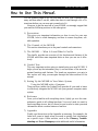 8
8
-
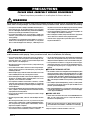 9
9
-
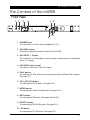 10
10
-
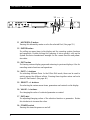 11
11
-
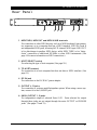 12
12
-
 13
13
-
 14
14
-
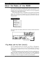 15
15
-
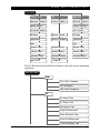 16
16
-
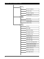 17
17
-
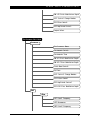 18
18
-
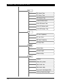 19
19
-
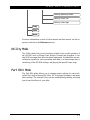 20
20
-
 21
21
-
 22
22
-
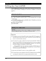 23
23
-
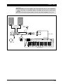 24
24
-
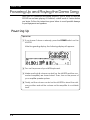 25
25
-
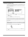 26
26
-
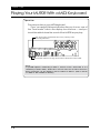 27
27
-
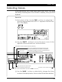 28
28
-
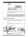 29
29
-
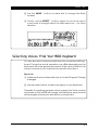 30
30
-
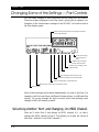 31
31
-
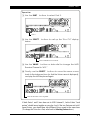 32
32
-
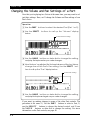 33
33
-
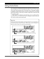 34
34
-
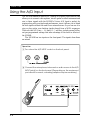 35
35
-
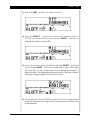 36
36
-
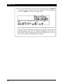 37
37
-
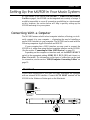 38
38
-
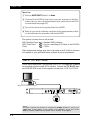 39
39
-
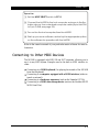 40
40
-
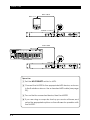 41
41
-
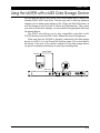 42
42
-
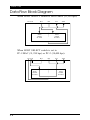 43
43
-
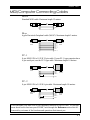 44
44
-
 45
45
-
 46
46
-
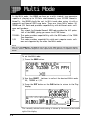 47
47
-
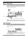 48
48
-
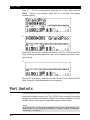 49
49
-
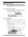 50
50
-
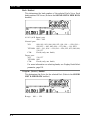 51
51
-
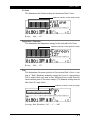 52
52
-
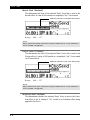 53
53
-
 54
54
-
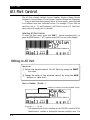 55
55
-
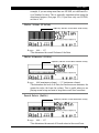 56
56
-
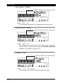 57
57
-
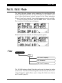 58
58
-
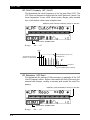 59
59
-
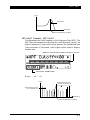 60
60
-
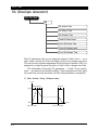 61
61
-
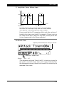 62
62
-
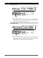 63
63
-
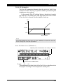 64
64
-
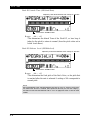 65
65
-
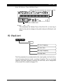 66
66
-
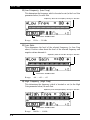 67
67
-
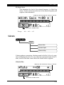 68
68
-
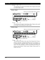 69
69
-
 70
70
-
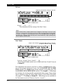 71
71
-
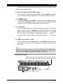 72
72
-
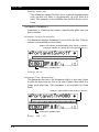 73
73
-
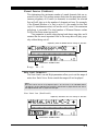 74
74
-
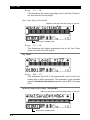 75
75
-
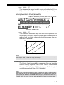 76
76
-
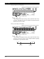 77
77
-
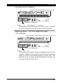 78
78
-
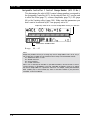 79
79
-
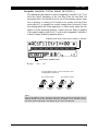 80
80
-
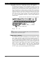 81
81
-
 82
82
-
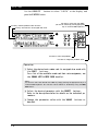 83
83
-
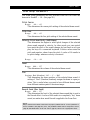 84
84
-
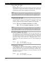 85
85
-
 86
86
-
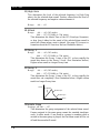 87
87
-
 88
88
-
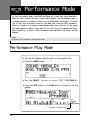 89
89
-
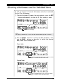 90
90
-
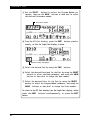 91
91
-
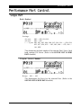 92
92
-
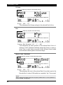 93
93
-
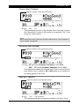 94
94
-
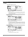 95
95
-
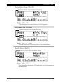 96
96
-
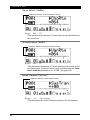 97
97
-
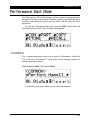 98
98
-
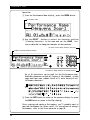 99
99
-
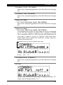 100
100
-
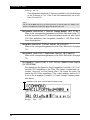 101
101
-
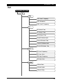 102
102
-
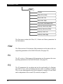 103
103
-
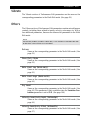 104
104
-
 105
105
-
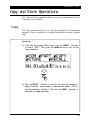 106
106
-
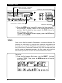 107
107
-
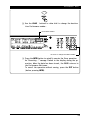 108
108
-
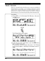 109
109
-
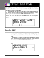 110
110
-
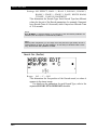 111
111
-
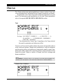 112
112
-
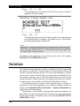 113
113
-
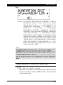 114
114
-
 115
115
-
 116
116
-
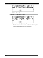 117
117
-
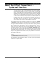 118
118
-
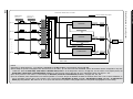 119
119
-
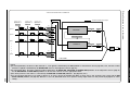 120
120
-
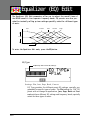 121
121
-
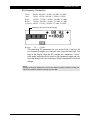 122
122
-
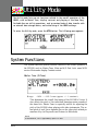 123
123
-
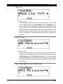 124
124
-
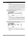 125
125
-
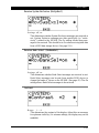 126
126
-
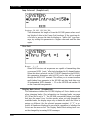 127
127
-
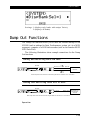 128
128
-
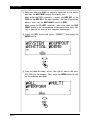 129
129
-
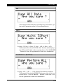 130
130
-
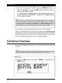 131
131
-
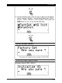 132
132
-
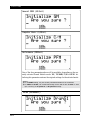 133
133
-
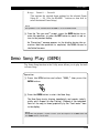 134
134
-
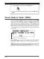 135
135
-
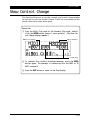 136
136
-
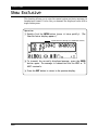 137
137
-
 138
138
-
 139
139
-
 140
140
-
 141
141
-
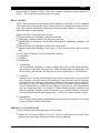 142
142
-
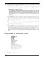 143
143
-
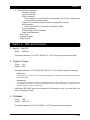 144
144
-
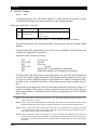 145
145
-
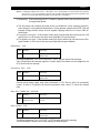 146
146
-
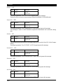 147
147
-
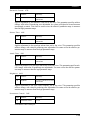 148
148
-
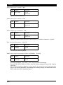 149
149
-
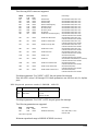 150
150
-
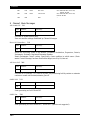 151
151
-
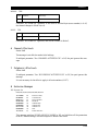 152
152
-
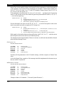 153
153
-
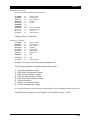 154
154
-
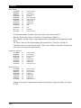 155
155
-
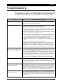 156
156
-
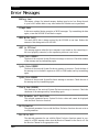 157
157
-
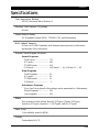 158
158
-
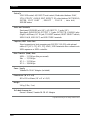 159
159
-
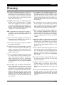 160
160
-
 161
161
-
 162
162
-
 163
163
-
 164
164
-
 165
165


Yamaha MU90R El manual del propietario
- Categoría
- Sintetizador
- Tipo
- El manual del propietario
en otros idiomas
- français: Yamaha MU90R Le manuel du propriétaire
- italiano: Yamaha MU90R Manuale del proprietario
- English: Yamaha MU90R Owner's manual
- Deutsch: Yamaha MU90R Bedienungsanleitung
- русский: Yamaha MU90R Инструкция по применению
- Nederlands: Yamaha MU90R de handleiding
- português: Yamaha MU90R Manual do proprietário
- dansk: Yamaha MU90R Brugervejledning
- polski: Yamaha MU90R Instrukcja obsługi
- čeština: Yamaha MU90R Návod k obsluze
- svenska: Yamaha MU90R Bruksanvisning
- Türkçe: Yamaha MU90R El kitabı
- suomi: Yamaha MU90R Omistajan opas
- română: Yamaha MU90R Manualul proprietarului
Artículos relacionados
-
Yamaha MU90R El manual del propietario
-
-
-
-
-
-
-
-
-