Daewoo RTE18GBBCD Manual de usuario
- Categoría
- Neveras
- Tipo
- Manual de usuario

MODELO PARTES COMPRESORMANO DE OBRA
Refrigerador 1 año 1 año 1 año
Garantía Limitada
Nota: Para Servicio o Asistencia, por favor llame : 1-877-DWE-ASC5, 1-877-DWE-SVC3
Modelos: RTE18GBWCD, RTE18GBBCD, RTE18GBTTD, RTE21GBWCD, RTE21GBBCD, RTE21GBTTD,
RTE18GSWCD, RTE18GSBCD RTE18GSSLD, RTE21GBWCS, RTE21GBBCS, RTE21GBSLS
30139U2802
Icemaker Installation .............17-22
23
41
43

1
50
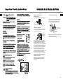
Reemplace la cubierta de acceso.
Apriete cualquier conexión que pueda presentar fugas.
Abra la llave del agua en la
válvula de cierre
Instalación de la Máquina de Hielos
Organice el cable de la tubería de manera que no vibre
contra la parte trasera del refrigerador o contra la pared.
Empuje el refrigerador hacia la pared.
Conecte el refrigerador
Verifique que haya
una conexión a
tierra adecuada
antes del uso.
Importante: Tenga a bien leer con atención
Para seguridad personal, este artefacto debe
conectarse a tierra de manera adecuada.
El cable de energía de este artefacto está equipado
con un enchufe de tres espigas (conexión a tierra)
que engancha con un tomacorriente de pared
de tres espigas (conexión a tierra) estándar para
minimizar el peligro de descarga eléctrica
proveniente de este artefacto. El cliente debe
hacer que un electricista calificado controle
el tomacorriente de pared y el circuito para verificar
que tengan una conexión a tierra adecuada.
Para el uso de este artefacto, es responsabilidad y
obligación del cliente cambiar un tomacorriente
estándar de dos patas por uno de tres patas con
adecuada conexión a tierra.
Bajo ninguna circunstacia corte o quite la
tercera pata (conexión a tierra) del cable
de energía.
S
TO
P
Inicie la máquina de hielos
Mueva el brazo de llenado a la posición ON (hacia abajo)
La máquina de hielos no empezará a operar hasta que
alcance su temperatura de operación de 15°F (–9°C) o
menor. Luego, empezará a operar automáticamente.
NOTA:En condiciones de menor presión del agua, la válvula
de agua puede encenderse hasta 3 veces para suministrar
suficiente agua a la máquina de hielos.
Brazo de llenado hacia
la posición STOP (hacia
arriba).
Brazo de llanado hacia
la posicón ON (hacia
abajo).

RTE18GSWCD
RTE18GSBCD
RTE18GSSLD
RTE21GBWCS
RTE21GBBCS
RTE21GBSLS
RTE18GBWCD
RTE18GBBCD
RTE18GBTTD
RTE21GBWCD
RTE21GBBCD
RTE21GBTTD
29.9 in
28.8 in
66.3 in
176.7 Lbs
14.2 cu ft
18.2 cu ft
BY RESISTENSE, TYPE SHEATH
32.9 in
32.0 in
66.7 in
220.5 Lbs
15.0 cu ft
20.8 cu ft
5.8 cu ft
BY RESISTENSE, TYPE SHEATH
R 600a
5.8 cu ft
49
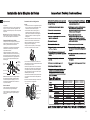
Dirija la tubería entre la línea del agua fría y el
refrigerador.
Dirija la tubería a través de un orificio perforado en
la pared o en el piso (detrás del refrigerador o del
gabinete de la base adyacente) lo más cerca posible
a la pared.
NOTA: Asegúrese de que haya suficiente tubería
adicional para permitir que el refrigerador se pueda
mover de la pared después de la instalación.
Dirija la tubería
Coloque la tuerca de compresión y férula para la
tubería de cobre (manga) en el extremo de la
tubería y conéctela a la válvula de cierre.
Asegúrese de que la tubería esté complemente
insertada en la válvula. Apriete la tuerca de
compresión firmemente.
Para tubería de plástico, inserte el extremo
moldeado de la tubería en la válvula de cierre y
apriete la tuerca de compresión hasta que esté
firmemente apretada a mano, luego apriete otro
giro con una llave. Apretar demasiado puede
causar fugas.
Conecte la tubería a la válvula
Abra el suministro principal de agua y lave
la tubería hasta que el agua esté limpia.
Cierre el agua en la válvula después de que un
cuarto (1 litro) de agua se haya eliminado por
la tubería.
Lave la tubería
NOTA: Se deberán seguir los Códigos 248CMR
de Plomería para el Estado de Massachusetts.
Las válvulas tipo silla son ilegales y su uso no
está permitido en Massachusetts. Consulte con
un plomero licenciado.
Válvula de cierre
tipo silla
Tuerca de
compresión
Tubería
de plastico
Tuerca de empaque
Válvula de salida
Férula (manga)
NOTAS:
• Antes de hacer la conexión al refrigerador, asegúrese
de que el cable de corriente del refrigerador no esté
conectado en el tomacorriente de la pared.
• Recomendamos instalar un filtro de agua si su
suministro de agua tiene arena o partículas que
podrían obstruir la malla de la válvula de agua del
refrigerador. Instálelo en la tubería del agua cerca
al refrigerador.
Retire los tornillos sosteniendo el lado derecho de la
cubierta de acceso. Doble la cubierta hacia atrás.
Retire la tapa flexible de plástico de la válvula del
del agua (conexión del refrigerador).
Coloque la tuerca de compresión y la férula (manga)
en el extremo de la tubería como se muestra.
Inserte el extremo de la tubería en la conexión de la
válvula del agua lo más que se pueda. Mientras sostiene
la tubería, apriete el accesorio.
Para tubería de plástico, inserte el extremo moldeado
de la tubería en la válvula de cierre y apriete la tuerca
de compresión hasta que esté firmemente apretada a
mano, luego apriete otra vuelta con una llave. Apretar
demasiado puede causar fugas.
Una la tubería a la abrazadera provista para sostenerla
en una posición vertical. Quizás necesite apalancar la
abrazadera.
Conecte la tubería al refrigerador
Tuerca de compresión
de 1/4″
Abrazadera
de la tubería
Tubería de 1/4″
Férula (manga)
Conexión del
refrigerador
Tubo de
Plastico
Una de las ilustraciones más abajo muestra como
luce la conexión en su refrigerador.
Instalación de la Máquina de Hielos

48
Cierre el suministro principal de agua
Abra el grifo más cercano por suficiente tiempo
para limpiar la tubería del agua.
Instale la válvula de cierre en la tubería del agua de
consumo más frecuentemente utilizada.
Seleccione una ubicación para la válvula que sea
fácilmente accesible. Es mejor conectarla en el
costado de una tubería vertical de agua. Cuando sea
necesario conectarla en una tubería horizontal de
agua, haga la conexión en la parte superior o al
lado, en vez de hacerlo en la parte de abajo,
para evitar retirar cualquier sedimento de la
tubería del agua.
Seleccione la ubicación de
la válvula
• Taladro eléctrico.
• Llave de 1/2″ o ajustable.
• Destornillador plano y de estrella.
• Dos tuercas de compresión de 1/4 de diametro exterior y″
2 férulas (mangas) – para conectar la tubería de cobre a la
válvula de cierre y la válvula del agua del refrigerador.
• Si su tubería existente de cobre para el agua tiene un
accesorio con vuelo en el extremo, necesitará un adaptador
(disponible en las tiendas de suministros de plomería) para
conectar la línea del agua al refrigerador o bien, podra
cortar el accesorio con vuelo con un cortador de tubos y
luego usar un accesorio de compresión.
• Válvula de cierre para conectar a la línea del agua fría. La
válvula de cierre deberá tener una entrada de agua con un
diámetro interno mínimo de 5/32″ en el punto de
conexión a la TUBERÍA DEL AGUA FRÍA. Las válvulas
de apagado tipo silla vienen incluidas en muchos kits de
suministro de agua. Antes de comprar, asegúrese de que
una válvula tipo silla cumple con los códigos de plomería
en su localidad.
Perfore un orificio de 1/4 ″ en la tubería del
agua (incluso si está usando una válvula auto
perforadora), usando una broca afilada. Retire
cualquier sobrante que resulte de perforar el
orificio en la tubería. Tenga cuidado de no permitir
que se filtre agua hacia el taladro. No perforar un
orificio de 1/4 ″ puede resultar en menor
producción de hielo o cubos más pequeños.
Perfore el orificio para
la válvula
Una la válvula de cierre a la tubería de agua fría
con la abrazadera para el tubo.
NOTA: Se deberán seguir los Códigos 248CMR
de Plomería para el Estado de Massachusetts. Las
válvulas tipo silla son ilegales y su uso no está
permitido en Massachusetts. Consulte con un
plomero licenciado.
Instale la válvula de cierre
Apriete los tornillos de la abrazadera hasta que la
arandela sellante empiece a hincharse.
NOTA: No apriete demasiado la tubería ya que
podría romperse.
Apriete la abrazadera del tubo
Tubería vertical
de agua fría
Válvula de
cierre tipo silla
Arandela
Extremo de entrada
Abrazadera
del tubo
Tornillo de la
abrazadera
Abrazadera
para el tubo
Instalación de la Máquina de Hielos

47
Cómo instalar la tubería
Antes de Iniciar
Esta instalación de la tubería del agua no está garantizada
por el fabricante del refrigerador o de la máquina de
hielos. Siga estas instrucciones cuidadosamente para
minimizar el riesgo de un daño costoso debido al agua.
El martilleo del agua (agua golpeando contra la tubería)
en la tubería de la casa puede causar daños a las partes
del refrigerador y conducir a un goteo o inundación por
el agua. Llame a un plomero calificado para corregir el
martilleo del agua antes de instalar la tubería del agua al
refrigerador.
Para evitar quemaduras y daños con el producto, no
conecte la tubería del agua a la tubería del agua caliente.
Si usa el refrigerador antes de conectar la tubería,
asegúrese de que el interruptor de corriente de la
máquina de hielos esté en la posición de O (apagado)
(en los modelos de interruptor de energía) o el brazo de
llenado la posición
STOP
(hacia arriba) (en los modelos
de brazo de llenado).
No instale la tubería de la máquina de hielos en lugares
donde la temperatura caiga por debajo del nivel de
congelamiento.
Al usar cualquier aparato eléctrico (como un taladro
eléctrico) durante la instalación, asegúrese de que el
aparato esté aislado o conectado de manera que evite el
peligro de una descarga eléctrica, o se opere por baterías.
Todas las instalaciones se deben realizar según los
requisitos del código local de plomería.
del agua
QUÉ NECESITA
Tubería de cobre para el refrigerador de 1/4 de
″
diámetro externo para conectar el refrigerador al
suministro de agua. Si usa cobre, asegúrese de que
ambos extremos de la tubería se corten uniformemente
Para determinar la cantidad de tubería que necesita: mida
la distancia desde la válvula del agua en la parte posterior
del refrigerador hasta el tubo de suministro de agua.
Luego agregue 8 pies (2.4 m). Asegúrese de que haya
suficiente tubería extra para permitir que el refrigerador
pueda separarse de la pared después de la instalación.
• Un suministro de agua fría. La presión del agua debe
estar entre 20 y 120 p.s.i. (1.4–8.1 bar).
Instalación de la Máquina de Hielos
Monte la máquina de hielos
Levante la máquina de hielos de manera que la extensión
del tubo de llenado encaje en la abertura de la taza de
llenado. Cuelgue la máquina de hielos sobre los dos
tornillos de montaje.
Asegúrese de que:
El cable de la corriente todavía esté firmemente en
el enchufe.
La extensión del tubo de llenado todavía esté en la
abertura de la taza de llenado. (Revise la parte posterior
del refrigerador para asegurar que el tubo de llenado
no se haya salido del orificio en el refrigerador).
Los tornillos de montaje de la máquina de hielos se
encuentran en la posición más alta de las ranuras de
montaje.
Luego apriete firmemente los tornillos de
montaje de la máquina de hielos.
Conecte la máquina de hielos
Sosteniendo la máquina de hielos en su lugar, inserte el
enchufe del cable de corriente en el orificio de la pared
posterior, asegurándose de que las patas y los orificios se
ajusten. Presione el enchufe firmemente en el orificio.
Asegure el enchufe en su lugar fijando los sujetadores en
cada costado del enchufe. Asegúrese de que los
sujetadores encajen en su lugar.
Instale la cubeta de hielos (Box Ice)
Coloque la cubeta de hielos debajo de la máquina
de hielos
Asegúrese de que el interruptor de corriente de la
máquina de hielos esté en la posición de O (apagado)
de la máquina de hielos
Extensión del tubo
de llenado
Abertura de la taza
de llenado
Cubeta de hielos
STOP
S
T
O
P
Válvula del agua instalada
Después de terminar la instalación de la tubería del agua
mueva el brazo de llenado de la maquina de hielos hacia
abajo en la posición (encendido).
El ciclo de la máquina de hielos no iniciará
sino hasta que la máquina de hielos y el
compartimento del congelador alcancen la
temperatura de operación.
IMPORTANTE

46
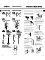
Instale la válvula del agua
Localice el enchufe conector macho en la válvula.
localice e inserte al conector hembra en la parte
inferior del refrigerador. Observe bien la forma
correcta de conectar ambos conectores.
Fije la válvula del agua al gabinete introduciendo
el tornillo de cabeza Phillips T1 4x14 mm del kit
en el orificio de la base del gabinete.
Conector
Terminales
macho de la
Tornillo de cabeza Phillips
Fije el tubo de Agua a el refrigerador
Presione el ensamble del Guide Cab W/Tube A1 as
una vez introducido en el respaldo del refrigerador.
Inserte los tornillos en los orificios del Cover Guide Cab
utilice los tornillos T1 4x16 mm.
Mantenga la tuberia fija aplicando cinta de algodón
Instalación de la Máquina de Hielos
Sujete el Guide Cab W/Tube A1 e inserte el conector
del Guide Cab W/Tube A2 as sobre entrada en la parte
plana. ″ .
Luego cubra el ensamble anterior con el Cover Guide
Cab W/Tube, asegurando que inserte correctamente
sobre las guías de la cara plana del Guide Cab W/Tube A1.
Inserte y deslice el tubo sobre el
orificio central de la parte superior,
en la parte trasera del refrigerador.
Presione el mismo firmemente sobre
la entrada para que quede ajustado
al refrigerador.
Dirija e instale la tubería plástica
Cinta adhesiva
del agua
Fije la tubería plástica del
agua a la parte posterior del
gabinete con la cinta adhesiva
de algodón, separando
como se muestra para tensar
la tubería.
Prepárese para la instalación
En el congelador, afloje los dos tornillos de montaje pero
no los retire por completo. Si su modelo no tiene ya los
tornillos en la pared del congelador, busque dos botones.
Retire los botones e inserte los dostornillos de cabeza
Exagonal Phillips. Los tornillos se deberán extender
aproximadamente 1/2″ (13mm) de la pared
del congelador.
Tornillos de montaje
Fije el interruptor en la posición
de O (apagado)
Fije el interruptor de corriente de la máquina de hielos
en la posición de O (apagado) hasta que el refrigerador
se conecte al suministro de agua para evitar la operación
prematura de la misma.
Instale la taza de llenado
Instale la taza de llenado de la máquina de hielos
(montada al costado) en la máquina de hielos
como se muestra.
Orificio para el
cable de amarre
S
T
OP
Brazo de llenado hacia
la posición STOP
Brazo de llenado hacia la
posición ON (hacia abajo).
STO
P
Taza de llenado de
la máquina de hielos
(hacia arriba).
de algodón
válvula de agua
hembra
en refrigerador
Tape Cotton
Screw
T1 4x16
sobre la tuberia plástica, aproximadamente 11/2
″
(40mm)

45
Instalación de la Máquina de Hielos
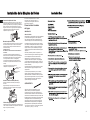
Antes de Empezar
Lea completamente los pasos antes de proceder.
PRECAUCIÓN –
Desconecte el refrigerador. Para eliminar
el peligro de una descarga eléctrica
durante la instalación, debe desconectar
el refrigerador de su tomacorriente.
Destornillador plano
y Phillips
Alicates
Herramientas Necesarias
Partes Incluidas
Retire la cubierta del enchufe
Vaya a la parte trasera del refrigerador. Busque
la etiqueta pequeña en la esquina superior
derecha y retírela. Luego deshágase de la misma.
Retire el conector blanco de la esquina superior
izquierda del fondo del congelador.
Retire la cubierta del enchufe con un destornillador
de pala plana.
Retire
conector
Retire la
etiqueta
Retire la cubierta
Use un destornillador Phillips para retirar la cubierta
de acceso del compartimiento del compresor. Esto
requiere retirar los seis tornillos que unen la cubierta
a la parte posterior de la caja del refrigerador.
Asegúrese de guardar los tornillos ya que la cubierta
de acceso se debe reinstalar más adelante para
asegurar que su refrigerador funcione correctamente.
Retire un lado del papel del sello para el tubo
de llenado de agua, deslice el sello por el
tubo y anexe el mismo a la parte trasera del
borde de la entrada del tubo de agua.
Instalacion del tubo de llenado
Conecte la tubería del agua
Asegúrese de que haya suficiente tubería plástica del
agua para que se extienda desde la válvula del agua
hacia bien adentro de la entrada de la tubería del
agua. Corte cualquier exceso de tubería.
Retire
tapa de tornillo
ST
OP
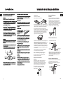
1 2 3 41
7 8
5
6-1
6
No. Part Name Q’ty/Unit
1 CASE ICE MAKER 1
2 SPECIAL C/T BOLT 2
3 BOX ICE 1
4 GUIDE I/WATER 1
5
GUIDE CAB W/TUBE A1 AS
1
6 1
7
COVER GUIDE CAB W/TUBE
1
8 SEAL W/TUBE A1
2
9
VALVE WATER AS
1
10
SCREW TAPPING
1
GUIDE CAB W/TUBE A2 AS
GUIDE CAB W/TUBE A1
SCREW TAPPING
11
12
2
1
6-2
6-3
6-4
trasera
Sello
Tubo de
plastico

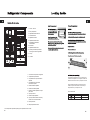
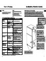
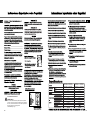
1. Contenedor de la puerta del congelador
2. Compartimiento para lacteos
3. Compartimiento de la puerta mediano
ajustable
4. Compartimiento de la puerta de
conservador completo
5. Parrilla de alambre ajustable
7. Cajón para almacenamiento de frutas y
8. Bandeja de hielos
9. Maquina para fabricar hielos
6. Parrilla completa ajustable
verduras con control de humedad
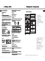
Your actual product may differ depending on the specification of the models
1. Freezer door bin
2. Dairy compartment
3. Adjustable half width door bin
4. Full width door bin
5. Adjustable wire shelf
6. Adjustable full width shelf
7. Humidity controlled crisper drawer
8. Ice tray
9. Ice maker
for storage of fruits and vegetables
44

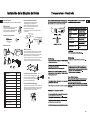
This refrigerator is designed to use an ice machine. Not
included in the refrigerator. You can request the sale and
installation to the service center by calling the call center.
Different models have different Ice maker that can be
installed, so please check whether the ice maker you
bought matches to your refrigerator or not.
Ice Maker Model
RTE18*****
RTE21*****
Refrigerator Model
30111-0058700-00
Code IM Model
30111-0058800-00
Kit Ice Maker Model
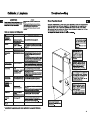
1. Contenedor de la puerta del congelador
2. Compartimiento para lacteos
3. Compartimiento de la puerta mediano
ajustable
4. Compartimiento de la puerta de
conservador completo
5. Parrilla de alambre ajustable
6. Parrilla de mediana ajustable
7. Parrilla de mediana ajustable con cajón
8. Cajón para carnes
10. Cajón para almacenamiento de frutas y
11. Bandeja de hielos
12. Maquina para fabricar hielos
9. Parrilla completa ajustable
para carnes
verduras con control de humedad
Your actual product may differ depending on the specification of the models
1. Freezer door bin
2. Dairy compartment
3. Adjustable half width door bin
4. Full width door bin
5. Adjustable wire shelf
6. Adjustable half width shelf
7. Adjustable half width shelf
8. Deli drawer
10. Humidity controlled crisper drawer
11. Ice tray
12. Ice maker
9. Adjustable full width shelf
with deli drawer
for storage of fruits and vegetables
43

42

41

40

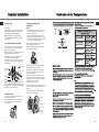
Lamp
Always use a LED lamp of similar
specification
The lamp is located under the top wall of the
refrigerator interior
Unscrew the LED lamp and remplace
Replace the cover in place by hooking the tabs into
the corresponding holes
39

38

37

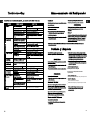
Reemplazo de la Lámpara
La lámpara se encuentra debajo de la pared superior del
Quite la cubierta de la lámpara
Desatornille la lámpara y reemplacela por otra similar.
Siempre use una lampara LED de similar
especificación.
36

35

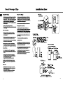
Before you begin
Read each step thoroughly before proceeding.
CAUTION – Unplug the Refrigerator.
To eliminate the danger of electric shock
during installation, you must unplug the
refrigerator from its electrical outlet.
Flat blade and Phillips
screwdrivers
Pliers
Tools you will need
Parts Included
Icemaker Installation
Remove the outlet cover
Remove the white connector from the upper left
Side
Back
Remove
plug
Remove and discard the white plug
from the lower left back corner of
the freezer wall.
Remove the cover
Use a Phillips head screwdriver to remove the
compressor compartment access cover. This
requires removing six screws which attach the
cover to the back of the refrigerator case.
Be sure to save the screws as the access cover must
be reinstalled later to ensure your refrigerator will
function properly.
Go to the back of the refrigerator. Find the small
label in the upper right corner and remove it
off. Then discard the label.
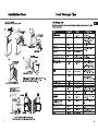
Install Guide Cab W/Tube A1
Remove
label
Remove one side of the seal paper for
Connect the water line
Make sure there is enough plastic water line to
extend from the water valve to well into the
water tube inlet. Cut off any excess tubing.
Remove
Cap screw
ST
OP
1 2 3 41
7 8
5
6-1
6
No. Part Name Q’ty/Unit
1 CASE ICE MAKER 1
2 SPECIAL C/T BOLT 2
3 BOX ICE 1
4 GUIDE I/WATER 1
5
GUIDE CAB W/TUBE A1 AS
1
6 1
6-1
COVER GUIDE CAB W/TUBE
1
6-2 SEAL W/TUBE A1
2
6-3
VALVE WATER AS
1
6-4
SCREW TAPPING
1
GUIDE CAB W/TUBE A2 AS
GUIDE CAB W/TUBE A1
SCREW TAPPING
11
12
2
1
6-2
6-3
6-4
Seal
Plastic Pipe
corner of the bottom of the freezer.
the water fill tube, slide the seal through
the tube and adhere it to the back edge
of the water tube inlet.
17 34

Icemaker Installation
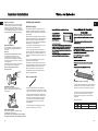
Fix the Water tube to the refrigerator
Route and attach the plastic water line
Install the water valve
Male
terminals
Phillips head
screw
Prepare for Installation
but do not screw them all the way out. If your model
does not have the screws already in the freezer wall,
look for two plug buttons. Remove the plug buttons
and insert the two phillips head screws. The screws
should extend approximately 1/2 ″ (13mm) out from
the freezer wall.
Set feeler arm to Stop position.
Move the feeler arm to the STOP (up) position
until the refrigerator is connected to the water
supply to prevent premature operation.
Hole for
wire tie
(Appearance may vary)
Mounting
screws
Inside the freezer, loosen the two moungting screws,
Install the Icemaker Fill Cup
Install the icemaker fill cup (side-mounted) into the
icemaker as shown.
S
TO
P
Feeler arm in the STOP
(up) position.
Feeler arm in ON (down)
position.
Icemaker
fill cup
ST
O
P
Hold the Guide Cab W / Tube A1 and insert the Guide
Then cover the previous assembly with the Cover
Cab W / Tube A2 connector onto the entrance on the
flat part.
Guide Cab W / Tube, ensuring that it fits correctly
into the guides on the flat side of the Guide
Cab W / Tube A1.
Insert and slide the tube over
the center hole at the top, at
the back of the refrigerator.
Press the same one firmly on
the entrance so that it is
adjusted to the refrigerator.
Attach the water valve to the cabinet by inserting
the T1 4x14 mm Phillips head screw from the kit
into the hole in the base of the cabinet.
Press the Guide Cab W / Tube A1 assembly as
soon as it is inserted into the back of the
refrigerator.Insert the screws into the holes in the
Cover Guide Cab using the T1 4x16 mm
screws.Keep the fixed pipe by applying cotton tape
over the plastic pipe, approximately 1 1/2 (40mm)
Tape Cotton
Screw
T1 4x16
Attach the plastic water pipe to the back of the
cabinet with the cotton adhesive tape, separating
as shown to tighten the pipe.
Cotton adhesive
Tape
Locate the male connector plug on the valve.
Locate and insert the female connector on the
bottom of the refrigerator. Observe the correct
way to connect both connectors.
Female
connector
18
á
33

Icemaker Installation
Installing the water line
This water line installation is not warranted by the
refrigerator or icemaker manufacturer. Follow these
instructions carefully to minimize the risk of expensive
water damage.
Water hammer (water banging in the pipes) in house
plumbing can cause damage to refrigerator parts and
lead to water leakage or flooding. Call a qualified
plumber to correct water hammer before installing the
water supply line to the refrigerator.
To prevent burns and product damage, do not hook
up the water line to the hot water line.
If you use your refrigerator before connecting the
water line, make sure the icemaker power switch is in
the O (off) position (on power switch models) or the
feeler arm is in the STOP (up) position (on feeler arm
models).
Do not install the icemaker tubing in areas where
temperatures fall below freezing.
When using any electrical device (such as a power
drill) during installation, be sure the device is double
insulated or grounded in a manner to prevent the
hazard of electric shock, or is battery powered.
All installations must be in accordance with local
plumbing code requirements.
BEFORE YOU BEGIN
WHAT YOU WILL NEED
″
connect the refrigerator to the water supply. If using
copper, be sure both ends of the tubing are cut square.
To determine how much tubing you need: Measure
the distance from the water valve on the back of the
refrigerator to the water supply pipe. Then add 8′
(2.4 m). Be sure there is sufficient extra tubing to
allow the refrigerator to move out from the wall
after installation.
Refrigerator copper tubing 1/4 outer diameter to
•
• A cold water supply. The water pressure must be
between 20 and 120 p.s.i. (1.4–8.1 bar).
Plug in the Icemaker
Holding the icemaker in place, insert the icemaker
power cord plug into the socket on the back wall,
making sure the prongs and holes are matched.
Press the plug firmly into the socket. Lock the plug
in place by clipping the restraints onto each side of
the plug. Make sure the restraints click into place.
Mount the Icemaker
Lift the icemaker so the fill tube extension fits in
the fill cup opening. Hang the icemaker on the
two screws.
Make sure:
The power cord is still firmly in the socket.
The fill tube extension extends into the
fill cup opening at the back of the icemaker.
(Check the rear of the refrigerator to make sure
the fill tube has not been pushed out of the back
of the refrigerator).
The icemaker mounting screws are located in the
uppermost position of the mounting slots.
Then securely tighten the icemaker
mounting screws.
Fill tube
extension
Fill cup
opening
Install the Ice Bucket
Place the ice bucket under the icemaker.
Make sure the icemaker power switch is in the
O (off) position.
Ice bucket
ST
O
P
ST
OP
Water Valve Installed
After water line installation is completed, set the
icemaket power switch to I (on).
The icemaking cycle will not begin until the icemaker
and freezer compartment reach operating temperature.
19
Compartimiento de productos Lácteos
PRECAUCIÓN
Este refrigerador está diseñado para usar una máquina de
hielo. No incluido en la nevera. Puede solicitar la venta e
instalación al centro de servicio llamando al call center.
Los diferentes modelos tienen diferentes máquinas de
hielo que se pueden instalar, así que verifique si la
máquina de hielo que compró es la correcta para su
refrigerador.
Ice Maker Model
RTE18*****
RTE21*****
Refrigerator Model
30111-0058700-00
Code IM Model
30111-0058800-00
Kit Ice Maker Model
Ice Maker (venta por separado)
32

Icemaker Installation
• Power drill.
• 1/2 ″ or adjustable wrench.
• Straight and Phillips blade screwdriver.
• Two 1/4 ″ outer diameter compression nuts and
2 ferrules (sleeves)—to connect the copper tubing to
the shutoff valve and the refrigerator water valve.
• If your existing copper water line has a flared fitting
at the end, you will need an adapter (available at
plumbing supply stores) to connect the water line to
the refrigerator OR you can cut off the flared fitting
with a tube cutterand then use a compression fitting.
• Shutoff valve to connect to the cold water line.
The shutoff valve should have a water inlet with a
minimum inside diameter of 5/32 ″ at the point of
connection to the cold water line. Saddle-type
shutoff valves are included in many water supply kits.
Before purchasing, make sure a saddle-type valve
complies with your local plumbing codes.
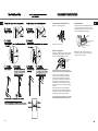
Shut off the main water supply
Turn on the nearest faucet long enough to clear
the line of water.
Install the shutoff valve on the nearest frequently used
drinking water line.
Choose a location for the valve that is easily
accessible. It is best to connect into the side of a
vertical water pipe. When it is necessary to connect
into a horizontal water pipe, make the connection
to the top or side, rather than at the bottom, to
avoid drawing off any sediment from the water pipe.
Choose the valve location
Drill a 1/4 ″ hole in the water pipe (even if using a
self-piercing valve), using a sharp bit. Remove any
burrs resulting from drilling the hole in the pipe.
Take care not to allow water to drain into the drill.
Failure to drill a 1/4 ″ hole may result in reduced
ice production or smaller cubes.
Drill the hole for the valve
Fasten the shutoff valve to the cold water pipe with
the pipe clamp.
NOTE: Commonwealth of Massachusetts Plumbing
Codes 248CMR shall be adhered to. Saddle valves
are illegal and use is not permitted in Massachusetts.
Consult with your licensed plumber.
Fasten the shutoff valve
Tighten the clamp screws until the sealing washer
begins to swell.
NOTE: Do not overtighten or you may crush the
tubing.
Tighten the pipe clamp
Washer
Inlet End
Pipe Clamp
Clamp Screw
Vertical Cold
Water Pipe
Saddle-Type
Shutoff Valve
Pipe Clamp
31

21
Icemaker Installation
Place the compression nut and ferrule (sleeve)
for copper tubing onto the end of the tubing and
connect it to the shutoff valve.
Make sure the tubing is fully inserted into the valve.
Tighten the compression nut securely.
For plastic tubing, insert the molded end of the
tubing into the shutoff valve and tighten
compression nut until it is hand-tight; then tighten
one additional turn with a wrench. Overtightening
may cause leaks.
NOTE: Commonwealth of Massachusetts Plumbing
Codes 248CMR shall be adhered to. Saddle valves
are illegal and use is not permitted in Massachusetts.
Consult with your licensed plumber.
Connect the tubing to the valve
Turn the main water supply on and flush out the
tubing until the water is clear.
Shut the water off at the water valve after about
one quart (1 liter) of water has been flushed
through the tubing.
Flush out the tubing
Saddle-Type
Shutoff Valve
Compression
Nut
Plastic tubing
Packing Nut
Outlet Valve
Ferrule (sleeve)
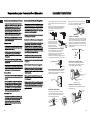
Route the tubing between the cold water line and
the refrigerator.
Route the tubing through a hole drilled in the wall
or floor (behind the refrigerator or adjacent base
cabinet) as close to the wall as possible.
NOTE: Be sure there is sufficient extra tubing
to allow the refrigerator to move out from the wall
after installation .
Route the tubing
NOTES:
• Before making the connection to the refrigerator,
be sure the refrigerator power cord is not
plugged into the wall outlet.
• We recommend installing a water filter if your
water supply has sand or particles that could clog
the screen of the refrigerator’s water valve. Install
it in the water line near the refrigerator.
Remove the screws holding the right side of the
access cover. Fold back the cover.
Remove the plastic flexible cap from the water
valve (refrigerator connection).
Place the compression nut and ferrule (sleeve)
onto the end of the tubing as shown.
Insert the end of the tubing into the water valve
connection as far as possible. While holding the
tubing, tighten the fitting.
For plastic tubing, insert the molded end of the
tubing into the water valve connection and tighten
compression nut until it is hand-tight; then tighten
one additional turn with a wrench.
Overtightening may cause leaks.
Fasten the tubing into the clamp provided to hold
it in a vertical position. You may need to pry open
the clamp.
Connect the tubing to the
1/4″ Compression Nut
Tubing Clamp
1/4″ Tubing
Ferrule (sleeve)
Refrigerator
Connection
Plastic
Tubing
One of the illustrations below will look like the
connection on your refrigerator.
refrigerator
30

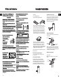
Icemaker Installation
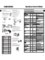
Tighten any connections that leak.
Turn the water on at the shutoff valve
Reattach the access cover.
Arrange the coil of tubing so that it does not vibrate
against the back of the refrigerator or against the
wall. Push the refrigerator back to the wall.
Plug in the refrigerator
Make sure proper
ground exists
before use.
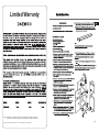
Important: Please read carefully for personal
safety, this appliance must be properly grounded
The power cord of this appliance is equipped
with a 3-prong (grounding) plug that mates with
a standard 3-prong (grounding) wall receptacle
to minimize the risk of electric shock hazard from
this appliance. The customer should have the
wall receptacle and circuit checked by a qualified
electrician to make sure the receptacle is properly
grounded.
Where a standard two-prong wall receptacle is
encountered, it is the personal responsibility and
obligation of the customer to have it replaced with
a properly grounded 3-prong wall receptacle.
Do not, Under any circumstances, cut or remove
the third (ground) prong from the power cord.
NOTE: In lower water pressure conditions, the
water valve may turn on up to 3 times to deliver
enough water to the icemaker.
Move the feeler arm to the ON (down) position. The
icemaker will not begin to operate until it reaches
its operating temperature of 15°F (–9°C) or below.
It will then begin operation automatically.
Start the Icemaker
Hole for
wire tie
S
T
OP
Feeler arm in the STOP
(up) position.
Feeler arm in ON (down)
position.
29

Limited Warranty
Note: For Service or Assistance, please call : 1-877-DWE-ASC5, 1-877-DWE-SVC3
Models: RTE18GBWCD, RTE18GBBCD, RTE18GBTTD, RTE21GBWCD, RTE21GBBCD, RTE21GBTTD,
RTE18GSWCD, RTE18GSBCD RTE18GSSLD, RTE21GBWCS, RTE21GBBCS, RTE21GBSLS
28

Tabla de Contenido
30139U2802
27
25-26
41
43
38-40
36-37
36
33-35
31-32
30
27-29
45-50
Instalación Fábrica de Hielo....

El uso de este electrodoméstico puede exponerlo a productos
químicos conocidos por el estado de California como causantes
de cáncer, nacimientos defectuosos u otros daños reproductivos.
Para más información vea la página web:
www.P65Warnings.ca.gov
CALIFORNIA PROPOSITION 65
ADVERTENCIA
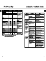
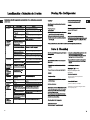
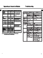
RTE18GSWCD
RTE18GSBCD
RTE18GSSLD
RTE21GBWCS
RTE21GBBCS
RTE21GBSLS
RTE18GBWCD
RTE18GBBCD
RTE18GBTTD
RTE21GBWCD
RTE21GBBCD
RTE21GBTTD
29.9 in
28.8 in
66.3 in
176.7 Lbs
14.2 cu ft
18.2 cu ft
32.9 in
32.0 in
66.7 in
220.5 Lbs
15.0 cu ft
20.8 cu ft
5.8 cu ft
R 600a
CONVECCION FORZADA
POR RESISTENCIA TIPO SHEATH
AUTOMATICO
CONVECCION FORZADA
POR RESISTENCIA TIPO SHEATH
AUTOMATICO
5.8 cu ft
25 26
-
 1
1
-
 2
2
-
 3
3
-
 4
4
-
 5
5
-
 6
6
-
 7
7
-
 8
8
-
 9
9
-
 10
10
-
 11
11
-
 12
12
-
 13
13
-
 14
14
-
 15
15
-
 16
16
-
 17
17
-
 18
18
-
 19
19
-
 20
20
-
 21
21
-
 22
22
-
 23
23
-
 24
24
-
 25
25
-
 26
26


Daewoo RTE18GBBCD Manual de usuario
- Categoría
- Neveras
- Tipo
- Manual de usuario
en otros idiomas
- English: Daewoo RTE18GBBCD User manual
