KPS SMD600 El manual del propietario
- Categoría
- Medir, probar
- Tipo
- El manual del propietario

1. General
1.1 Introducción
• Provisto con pantalla LCD de 21mm. Indicación máxima 1999.
• 6 escalas desde 2nF a 200µF.
• 4 escalas desde 2mH a 2H.
• Alta precisión en la medición.
• Cero automático
• Convertidor-integrador A/D de doble pendiente
• Indicación por sobrecarga de “1”
• Punta de prueba con diseño de seguridad.
• Tamaño: 31.5mm x 91mm x 189mm (HxAxL)
• Peso: 240g (incluyendo la batería)
1.2 Características
2. Especificaciones
La precisión está especificada para un período de un año
después de la calibración y entre 18ºC -28ºC (64ºF a 82ºF)
con humedad relativa de 80%.
2.1 General
Alimentación Pila 9V NEDA 1604 ó 6F 22 006P
Indicador de
batería baja aparece en pantalla
Protección por
fusible 100mA/250V
Ajuste a cero Automático (excepto para la escala de 2nF,
normalmente tiene una capacidad parásita de
0-3pF).
Temperatura de
trabajo
Temperatura de
almacenamiento
0°C a 40°C (32°F a 104°F)
-10°C (14°F a 122°F)
2.2 Especificaciones técnicas
L(inductancia)
Escala Resolución Precisión
2mH
20mH
200mH
2H
1μH
10μH
100μH
1mH
L(inductancia)
Frecuencia
de prueba
Corriente a través de la
inductancia bajo test
900Hz
900Hz
900Hz
900Hz
150μA
150μA
150μA
150μA
C(Capacidad)
Escala Resolución Precisión
± 1% de la escala total ± 1 dígito
± 1% de la escala total ± 1 dígito
± 1% de la escala total ± 1 dígito
± 2% de la escala total ± 1 dígito
± 2% de la escala total ± 1 dígito
± 2% de la escala total ± 1 dígito
2nF
20nF
200nF
2μF
20μF
200μF
1pF
10pF
100pF
1000pF
0.01μF
0.1μF
C(Capacidad)
Frecuencia
de prueba
Tensión a través de
la capacidad bajo test
900Hz
900Hz
900Hz
900Hz
90Hz
90Hz
150mV
150mV
150mV
150mV
150mV
15mV
Coeficiente de temperatura:
Inductancia: Escala 2mH, 20mH, 200mH 0.2% /ºC.
Escala 2H 0.5%/ºC
Capacidad: Escala 2nF, 20nF, 200nF 0.1% /ºC
Escala 2µF, 20µF, 200µF 0.2%/ºC.
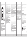
MANUAL DE INSTRUCCIONES
INSTRUCTION MANUAL
Comprobador digital LC
LC digital checker
Este comprobador digital LC proporciona una lectura directa de
inductancia y capacitancia en una pantalla LCD de 3 ½ dígitos.
Seis escalas para medir desde 1pF a 200µF y cuatro escalas para
medir desde 1µH a 2H proporcionan lecturas precisas para la
medición de todas las inductancias y capacidades utilizadas en
laboratorios, producción, tiendas y escuelas de ingeniería electrónica.
Su funcionamiento mediante batería, peso ligero y pequeño tamaño
hacen de este medidor un instrumento verdaderamente portátil.
± 2% de la escala total ± 1 dígito
± 2% de la escala total ± 1 dígito
± 2% de la escala total ± 1 dígito
± 5% de la escala total ± 1 dígito

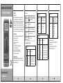
3. Panel frontal
1. Pantalla LCD
2. Rueda selectora
3. Terminales de entrada
4. Instrucciones de funcionamiento
4.1 Precaución antes de la medición
1. Asegúrese de que la pila está bien colocada y conectada.
2. Observe la polaridad al conectar los condensadores
polarizados.
3. Descargue por completo todos los condensadores.
4. Nunca aplique tensión en los terminales de prueba,
puede ocasionar daños serios.
4.2 Consideraciones
1. Este medidor LC está diseñado para medir el valor de la
capacidad de condensadores y el valor de la inductancia
de bobinas. No está diseñado para determinar el factor “Q”.
Debido a que la frecuencia de medición es solamente de
900Hz, este medidor no es apto para medir bobinas que se
utilizan en circuitos de alta frecuencia. En ese caso, se
obtendrá una lectura errónea.
2. Al medir los componentes en un circuito, este circuito debe
estar desconectado de la alimentación y descargado antes
de conectar los cables de prueba.
3. Los instrumentos utilizados en entornos con polvo deben
desmontarse y limpiarse periódicamente.
4. No exponga el instrumento directamente al calor del sol
durante periodos prolongados.
5. Antes de retirar la pila y el fusible, asegúrese de que el
instrumento está desconectado de cualquier circuito y la
rueda selectora está en la posición OFF.
6. Para todas las mediciones, debe conectar el cable de
prueba negro al terminal “-“ y el cable de prueba rojo al
terminal “+”.
4.3 Procedimiento de medición de la inductancia (L)
1. Seleccione la escala para la inductancia máxima esperada.
2. Conecte las pinzas de cocodrilo en los cables de prueba
o inserte los extremos de la bobina en las tomas de
medición del medidor.
3. Lea la pantalla. El valor de la medición es de lectura directa
y la unidad eléctrica (mH, H) está indicada.
4. Cuando se muestra el símbolo “1”, indica una situación de
escala sobrepasada y tendrá que seleccionar una escala
mayor.
5. Si la pantalla indica un uno seguido de ceros a la izquierda
en la lectura, cambie a la siguiente escala menor para
mejorar la resolución de la medición.
4.4 Procedimiento de medición de la capacidad (C)
1. Seleccione la escala para la capacidad máxima esperada.
2. Conecte las pinzas de cocodrilo en los cables de prueba
o inserte los extremos del condensador en las tomas de
medición del medidor.
3. Lea la pantalla. El valor de la medición es de lectura directa
y la unidad eléctrica (nF, µF) está indicada.
4. Cuando se muestra la figura “1”, indica una situación de
escala sobrepasada y tendrá que seleccionar una escala
mayor.
5. Si la pantalla indica un uno seguido de ceros a la izquierda
en la lectura, cambie a la siguiente escala menor para
mejorar la resolución de la medición.
5. Mantenimiento
* Cuando en la esquina izquierda de la pantalla LCD aparezca
es necesario cambiar la pila. Retire los tornillos de la tapa
trasera y abra la carcasa. Sustituya la pila agotada por una
nueva.
* El fusible rara vez necesita reemplazo y casi siempre se
funde a causa de un error del operador. Abra la carcasa
como se menciona arriba, y después saque la PCB de la
tapa delantera. Cambie el fusible fundido por uno con las
mismas especificaciones (100mA/ 250V de acción rápida).
* Si se observa cualquier anormalidad o fallo, el medidor no
podrá ser utilizado ya que deber comprobado.
* Nunca utilice el medidor a menos que la tapa trasera esté
en su lugar y correctamente sujeta.
* No utilice abrasivos o disolventes en el medidor. Para
limpiarlo utilice un trapo húmedo y detergente suave.
6. Accesorios
6.2 Cómo utilizar la funda
La funda se utiliza para proteger el medidor y hacer que las
mediciones sean más cómodas. Viene con 2 soportes
instalados de forma conjunta que permiten:
1. Sujetar el medidor en un ángulo estándar.
2. Sujetar el medidor en un ángulo pequeño utilizando el
soporte pequeño.
3. Colgar el medidor en la pared utilizando el soporte
pequeño. Saque el soporte pequeño de la parte trasera
del soporte largo e insértelo en los agujeros localizados
en la parte superior de la funda.
KPS SOLUCIONES EN ENERGÍA, S.L.
Parque Empresarial de Argame,
C/Picu Castiellu, Parcelas i-1 a i-3
E-33163 Argame, Morcín
Asturias, España, (Spain)
6.1 Proporcionado con el medidor de capacidad
Cables de prueba
Batería: 1 x 9V NEDA 1604 ó 6F 22006p
Manual de instrucciones
Funda

1. General
1.2 Features
* 21mm LCD display provided. MAX. indication 1999.
* 6 Ranges from 2nF to 200μF.
* 4 Ranges from 2mH to 2H.
* High accuracy in measuring.
* Zero automatic.
* Dual - Slope integration A/D converter.
* Overload indication of " 1 ".
* Safety designed test probe.
* Size: 31.5mm x 91mm x 189mm ( H x Wx L).
* Weight: 240g ( including battery ).
2. Specifications
Accuracy is specified for a period of one year after
calibration and at 18°C t0 28°C ( 64°F t0 82°F ) with
relative humidity to 80%.
2.1 General
POWER SUPPLY 9V battery NEDA 1604 or 6F 22 006P
LOW BATTERY
INDICATION appears on the display
FUSE
PROTECTION 100mA/250V
ZERO
ADJUSTMENT
Automatic (except 2nF range, typically
have 0-3pF circuit stray capacitance)
OPERATING
TEMPERATURE
STORAGE
TEMPERATURE
0°C to 40°C (32°F to 104°F)
-10°C (14°F to 122°F)
2.2 Electrical Specifications
L(inductance)
Range Resolution Accuracy
2mH
20mH
200mH
2H
1μH
10μH
100μH
1mH
±2% of full scale ±1 digit
±2% of full scale ±1 digit
±2% of full scale ±1 digit
±5% of full scale ±1 digit
L(inductance)
Test Frequency Current through
inductance under test
900Hz
900Hz
900Hz
900Hz
150μA
150μA
150μA
150μA
C(Capacitance)
Range Resolution Accuracy
±1% of full scale ±1 digit
±1% of full scale ±1 digit
±1% of full scale ±1 digit
±2% of full scale ±1 digit
±2% of full scale ±1 digit
±2% of full scale ±1 digit
2nF
20nF
200nF
2μF
20μF
200μF
1pF
10pF
100pF
1000pF
0.01μF
0.1μF
C(Capacitance)
Test Frequency Voltage across
Capacitance under test
900Hz
900Hz
900Hz
900Hz
90Hz
90Hz
150mV
150mV
150mV
150mV
150mV
15mV
Temperature coefficient:
Inductance: Range 2mH, 20mH, 200mH 0.2%/°c.
Range 2H 0.5%/°c.
Capacita n ce: Range 2nF, 20nF, 200nF 0.1 %/°c.
Range 2μF, 20°F, 200μF 0.2%/°c.
1.1 Introduction
This Digital LC Meter gives a direct reading of inductance
and capacitance on a 3 1/2 digits LCD display. Six ranges
from 1pF t0 200μF and four ranges from 1μH
to 2H give precision readings, which includes virtually all
inductance and capacitance used in electronic
engineering laboratory, production, service shops and
schools. Its battery operation, light weight,
and small size make it a truly portable instrument.

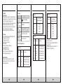
3. Front Panel
1. LCD DISPLAY
2. ROTARY SWITCH
3. INPUR JACKS
4. Operating Instruction
4.1 Caution Before Measurement
1. Be sure that batteries are correctly placed in the
battery case and connected to the battery snap.
2. Observe polarity when connecting polarized
capacitors.
3. Full discharge any capacitors.
4. Never apply voltage to the test jacks, serious
damage may result.
4.2 Consideration
1. This LC meter is intended for measuring the
capacitance value of a capacitor and the mductance
value of an inductor. it is not intended for determining
the “Q” factor . As the measuring frequency is only
900Hz, this meter is not suitable for measuring
inductors which are used in the high frequency
circuit. in such a case, misleading readings may
be obtained.
2. When measuring components within circuit that
circuit must be switched off and de-energized before
connecting the test leads.
3. Instruments used in dusty environments should be
stripped and cleaned periodically.
4. Do not leave the instrument exposed to direct heat
from the sun for long periods.
5. Before removing the battery and fuse. ensure the
instrument is disconnected from any circuit and the
ROTARY switch is in the OFF position.
6. For all measurements, should connet the BLACK
test lead into " - ' terminal and the RED tesl lead
into " + " terminal.
4.3 Inductance ( L) Measurement Procedure
1. Select the range switch for the maximum expected
inductance.
2. Conncet the alligator clips to the inductor leads or
insert leads of the inductor into meter's measuring
socket.
3. Read the display. The measuring value is direct
reading and the electrical unit ( mH, H ) is indicated.
4. When only the figure " 1 " is displayed, it indicates
overrange situation and the higher range has to
be selected.
5. If the display indicates one of more reading zeros,
shift to the next lower range scale to improve the
resolution of the measurement.
4.5 Capacitance (C) Measuring Procedure
1. Select the range switch for the maximum expected
capacitance.
2. Connect the alligator clips to capacitor leads or insert
leads of the capacitor into meter's measuring socket.
3. Read the display. The measuring value is direct
reading and the electrical unit (nF, μF) is indicated.
4. When only the figure " 1 " is displayed, it indicates
overrange situation and the higher range has to be
selected.
5. If the display indicates one of more reading zeros,
shift to the next lower range scale to improve the
resolution of the measurement.
5. Maintenance
* When the left corner of LCD display show ” ”. it is
necessary to replace the battery. Remove screws on
the back cover and open the case. Replace the
exhausted battery with a new one.
* Fuse rarely need replacement and blow almost always
as a result of the operator's error. Open the case as
mentioned above, and then take the PCB out from the
front cover. Replace the blown fuse with same ratings
( 100mA/250V quick acting ).
* If any faults or abnormalities are observed , the meter
can not be used any more and it has to be checked out.
* Never use the meter unless the back cover is in place
and fastened fully ,
* Do not use abrasives or solvents on the meter, use a
damp cloth and mild detergent only .
6. Accessories
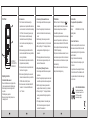
6.2 How To Use The Holster
The holster is used to protect the meter and to make
the measurement more comfortable, It comes with
two stands installed together. The figure shows how
to use the holster to:
1. Support the meter with a standard angle.
2. Support the meter with a small angle using the
little stand.
3. Hang the meter on the wall using the little stand.
Take the little stand off from the back side of the
large stand and insert it into holes located upper
on the holster.
KPS SOLUCIONES EN ENERGÍA, S.L.
Parque Empresarial de Argame,
C/Picu Castiellu, Parcelas i-1 a i-3
E-33163 Argame, Morcín
Asturias, España, (Spain)
6.1 Supplied with the Capacitance Meter
Test Leads
Battery: 1 x 9V NEDA1604 or 6F 22 006p
Operating Manual
Holster
-
 1
1
-
 2
2
-
 3
3
-
 4
4


KPS SMD600 El manual del propietario
- Categoría
- Medir, probar
- Tipo
- El manual del propietario
En otros idiomas
- English: KPS SMD600 Owner's manual
Documentos relacionados
Otros documentos
-
Velleman DVM6243 Manual de usuario
-
Wavetek 23XT25XT27XT28XT Manual de usuario
-
Velleman DVM6013 Especificación
-
Mastech MS6013 Guía del usuario
-
Amprobe LCR55A Inductance Capacitance Resistance Meter Manual de usuario
-
-
Ega Master 51643 El manual del propietario
-
B&K 2704C Instrucciones de operación
-
 Wavetek Meterman HD115B Manual de usuario
-
