La página se está cargando ...

Opciones auxiliares
A fin de agilizar y facilitar la
instalación es posible que su
instalación precise algunos de los
equipos auxiliares que aparecen
a continuación:
WD100 Conducto de pared
CFWG100 Rejilla de pared
XCT100 Trampa de
condensación
DGW/B Rejilla de puerta
para circulación de
aire
SP100 Placa de espiga
XAA Adaptador de
ladrillo ventilador
VC10 Respiradero de
enfriamiento
WT10 Juego de conducto
de terminación
XF/FM Conducto plano
(metal / plástico)
(Plástico 234 x 29 /
Metal 230 x 25)
VK10 Juego de
ventilación de
pared
KHWG Rejilla de pared
(negra)
FD100 Conducto flexible
WDC5 Pinzas de tornillo
sinfín
XCMK Juego para
montaje en techo
XBP Persiana de tiro
posterior en línea
EFT Adaptador de
juego de
terminación de
ajuste fácil
PDXGF Filtro de grasas
Piezas de repuesto
A continuación se ofrece una
relación de piezas de repuesto
disponibles. Véase la última
página de este folleto para
obtener información sobre
pedidos:
41761SK Motor (DX400)
41762SK Motor (DX400PC)
41763SK Motor (CF40)
41764SK Conjunto de PCI
(DX400T)
41765SK Conjunto de PCI
(DX400RS)
41766SK Conjunto de PCI
(CF40)
41767SK Conjunto de PCI
(CF40TD)
41768SK Conjunto de PCI
(CF40RSTD)
41774SK Cubierta frontal c/c
difusor
(DX400/CF40)
41771SK Moldura acústica
(Toda la gama)
41772SK Conjunto de
cordón (Toda la
gama)
ES
a
A
B
C
D
La página se está cargando ...
La página se está cargando ...

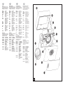
Cableado de las conexiones eléctricas
1. Aísle el suministro eléctrico y retire todos los
fusibles. La caja de terminales es apta para cables
de hasta 2.5mm
2
.
2. Utilice un conmutador de aislamiento de dos polos con
una separación mínima de contacto de 3 mm en
ambos polos.
3. Utilice un cable de 3 almas o 4 almas de la
clasificación correcta, dependiendo de la aplicación.
4. Cablee el ventilador como se muestra en la Fig.
F y
utilice la abrazadera para cables que se proporciona
a fin de asegurar el cable. Compruebe el modelo de
ventilador con el diagrama.
DX400: “LH” = Vivo (Alta
velocidad) / “LL” = Vivo (Baja velocidad).
5. Vuelva a colocar la tapa de la caja de terminales
5 y
apriete los tornillos de sujeción.
6. Consulte el apartado
“Ajustes del usuario” si desea
utilizar otros ajustes que no sean los ajustados en
fábrica.
7. Vuelva a colocar la cubierta frontal
2 (Fig. C).
8. Conecte el cable del conmutador de aislamiento al
cableado del suministro eléctrico y vuelva a
comprobar la instalación.
9. Antes de volver a conectar la electricidad, instale los
fusibles.
10. Para circuitos de cableado fijo, el fusible de seguridad
para el aparato no debe superar 5A.
Ajustes del usuario
Antes de llevar a cabo cualquier ajuste, aísle el
ventilador del suministro eléctrico de la red,
compruebe las especificaciones que se ofrecen
seguidamente, a fin de ver qué características son
aplicables al modelo de ventilador.
1. Retire la cubierta frontal y vuélvala a colocar después
del ajuste .
C)
DX400 / DX400PC / DX400RS
Estos modelos de ventiladores no pueden ser ajustados
por el usuario.
DX400T
1. 1. El periodo de rebase del temporizador puede
ajustarse entre aproximadamente 30 segundos y 20
minutos. Utilice un destornillador de electricista y gire
el tornillo “T” (Fig.
D), hacia la derecha para
incrementar el tiempo o hacia la izquierda para
reducirlo. (El ajuste de fábrica es de
aproximadamente 10 minutos).
CF40
1. El ajuste de humedad puede ajustarse entre
aproximadamente 50% y 90% de humedad relativa.
Utilice un destornillador de electricista u gire el tornillo
“RH” (Fig.
D) hacia la derecha para incrementar el
ajuste de humedad relativa y hacia la izquierda para
reducirla. (Nota: el ventilador es más sensible a 50%
de HR que a 90%).
CF40TD / CF40RSTD
1. El periodo de rebase del temporizador puede
ajustarse entre aproximadamente 30 segundos y 20
minutos. Utilice un destornillador de electricista y gire
el tornillo “T” (Fig.
D), hacia la derecha para
incrementar el tiempo o hacia la izquierda para
reducirlo. (El ajuste de fábrica es de
aproximadamente 10 minutos).
2. El ajuste de humedad puede ajustarse entre
aproximadamente 50% y 90% de humedad relativa.
Utilice un destornillador de electricista u gire el tornillo
“RH” (Fig.
D) hacia la derecha para incrementar el
ajuste de humedad relativa y hacia la izquierda para
reducirla. (Nota: el ventilador es más sensible a 50%
de HR que a 90%).
Uso del ventilador
DX400
Ponga en funcionamiento el ventilador utilizando el
interruptor de encendido / apagado externo. Repita el
procedimiento para apagarlo. La velocidad del ventilador
está preajustada por el instalador, bien a velocidad rápida
o lenta. (Si se ha instalado un inversor de corriente
entonces el usuario puede cambiar la velocidad de rápida
a lenta.)
DX400PC
Secuencia de funcionamiento del cordón:
Ventilador apagado (luz apagada)
Tire del cordón una vez, el ventilador se pone en
funcionamiento en velocidad rápida (“la luz II” está
encendida – alta intensidad)
Tire del cordón otra vez, el ventilador se pone en
funcionamiento en velocidad lenta (“la luz II” está
encendida – baja intensidad)
Tire del cordón otra vez, el ventilador se apaga (luz
apagada)
El instalador puede ajustar un interruptor interno a fin de
ofrecer extracción continua de fondo cuando está
“apagado”.
DX400T
Accione el ventilador utilizando el interruptor de encendido
/ apagado.
Cuando se encienda el interruptor, el ventilador funcionará
a velocidad rápida.
Cuando se apague el interruptor, el ventilador continúa
funcionando a velocidad lenta durante el periodo de
rebase del temporizador ajustable (“la luz I” está
encendida e indica que el ventilador está funcionando en
modo manual)
El instalador puede ajustar un interruptor interno a fin de
ofrecer extracción continua de fondo cuando está
“apagado”.
Función de demora de puesta en marcha encendida o
apagada.
Esta función la ajusta el instalador a fin de ofrecer una
demora de puesta en marcha de 2 minutos cuando se
enciende el ventilador utilizando el interruptor de
encendido / apagado externo.
DX400RS
Accione el ventilador utilizando el interruptor de encendido
/ apagado.
Seleccione velocidad rápida o lenta utilizando el
interruptor remoto. El instalador puede ajustar un
interruptor interno a fin de ofrecer extracción continua de
fondo cuando está “apagado”.
La “luz I” superior está encendida a alta densidad cuando
el ventilador funciona a velocidad rápida, y a intensidad
baja cuando el ventilador funciona a velocidad lenta. La
luz se apaga cuando el ventilador está apagado o
funciona a extracción lenta.
CF40 / CF40TD
Funcionamiento conmutado
El ventilador puede cablearse con un interruptor de
encendido / apagado separado. El ventilador funciona a la
velocidad de condensación cuando se enciende. La “luz I”
superior está encendida cuando se enciende el interruptor
de encendido / apagado separado. Cuando está apagado,
el ventilador continuará funcionando si el nivel de
humedad es superior al establecido por el tornillo de
ajuste “RH”. CF40TD solamente: Cuando se apaga, el
ventilador continúa funcionando durante el periodo de
rebase del temporizador ajustable.
Funcionamiento de la condensación
El ventilador se pine en funcionamiento a la velocidad de
control de condensación cuando la humedad relativa
supera el nivel establecido y se apaga cuando la
humedad relativa baja.
Funcionamiento de refuerzo
Secuencia del cordón:
Funcionamiento de condensación automático (Ambas
luces apagadas)
Tire del cordón una vez, el ventilador se pone en
funcionamiento en velocidad rápida (“luz II” inferior está
encendida – alta intensidad).
Tire del cordón otra vez, el ventilador se pone en
funcionamiento en la velocidad de condensación manual
(“luz II” inferior está encendida – baja intensidad)
Tire del cordón otra vez, el ventilador funciona a velocidad
de condensación automática (ambas luces apagadas)
Función lenta encendida o apagada
Esta función la ajusta el instalador a fin de ofrecer
extracción de fondo continua, cuando el nivel de humedad
es inferior al establecido por el tornillo de ajuste “RH” y el
ventilador está en el modo de condensación automático.
CF40TD solamente
Función de demora de puesta en marcha encendida o
apagada
Esta función la ajusta el instalador a fin de ofrecer una
demora de puesta en marcha de 2 minutos cuando el
ventilador se enciende utilizando un interruptor de
encendido / apagado separado.
CF40RSTD
Funcionamiento de la condensación
El ventilador funciona a la velocidad de control de la
condensación, cuando la humedad relativa supera el nivel
establecido, y se apaga cuando baja la humedad.
Funcionamiento de refuerzo
Accione el ventilador utilizando el interruptor de encendido
/ apagado. Seleccione velocidad rápida o lenta utilizando
el interruptor remoto. Cuando está apagado, el ventilador
continúa funcionando durante el periodo de rebase
ajustable. El instalador puede ajustar un interruptor interno
a fin de que el ventilador continúe ofreciendo extracción
de fondo continua cuando esté “Apagado”. La “luz I”
superior está encendida a intensidad alta cuando el
ventilador está funcionando a velocidad rápida, y a
intensidad baja cuando el ventilador está funcionando a
velocidad lenta. La luz está apagada cuando el ventilador
está Apagado o funcionando en el modo de extracción
lenta.
Limpieza
1. Antes de limpiar el ventilador, aísle el suministro
eléctrico de la red.
2. Limpie únicamente la superficie exterior del ventilador,
utilizando un paño húmedo sin pelusas.
3. No utilice detergentes fuertes, disolventes ni
limpiadores químicos.
4. Deje que el ventilador se seque completamente antes
de volver a usarlo.
5. Aparte de la limpieza, el ventilador no precisa ningún
otro mantenimiento.
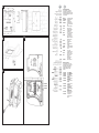
Clave
Véase el diagrama E
1. Placa deflectora
2. Cubierta frontal
3. Impulsor
4. Tornillos de sujeción
5. Tapa de terminales
6. Caja del ventilador
7. Espiga circular
8. Tornillos de abrazadera y tirafondos – 3 x
9. Abrazaderas del cuerpo del ventilador – 3 x
10. Perímetro
11. Tornillos de techo 25 mm de largo 4 x (Diagrama
B)
12. Cinta de espuma
PARA EL BENEFICIO DEL USUARIO DEJE ESTE
FOLLETO CON EL VENTILADOR.
For speed and ease of Installation, your
installation may require some of the Ancillaries
indicated in “Ancillary Options”.
If installing on a wall (surface mounting)
1. Mark on the wall the centre of the duct hole A.
2. Use this centre to cut an opening through the wall
117mm diameter, with a slight fall to the exterior.
3. Fit the wall tube, not supplied, and mortar into
place.
If installing in a wall (flush mounting)
1. Mark on the wall the centre of the duct hole A,
and drill a pilot hole through both walls.
2. Use the centre to mark a rectangular hole for the
inner wall using the dimensions A.
3. Cut the rectangular hole through the inner wall.
4. Go outside and cut a 117mm diameter hole in the
outer wall using the small hole as the centre.
5. Measure the wall thickness.
Cut the wall tube (WD100), not supplied, so that it
is 85mm less than the wall thickness.
If installing on a ceiling (surface mounting)
This method requires a space above the ceiling, such
as a loft or attic, to provide access for 100mm internal
diameter ducting, or a minimum 70mm void using flat
ducting.
1. Mark on the ceiling the centre of the duct hole A,
avoiding ceiling joists and buried cables etc..
2. Cut a 117mm diameter hole using the marked
centre.
If installing in a ceiling (flush mounting)
For 100mm diameter ducting:
This method requires a space above the ceiling, such
as a loft or attic, to provide access for 100mm internal
diameter ducting.
1. Mark a rectangular hole using the dimensions B.
2. Cut the hole, avoiding ceiling joists and buried
cables etc.
For flat ducting:
• This fan can be installed within a 140mm void with
the circular spigot
7.
Preparing the fan for installation
1. Remove the front cover 2 (Fig.C)
2. Fit the foam tape !™ supplied around the circular
spigot
7 (Fig.E).
3. Remove the electrical cover 5 (Fig.E).
Setting the condensation speed
CF40 / CF40TD / CF40RSTD Only (Fig.D)
4. The correct condensation control speed should be
selected to suit the room size in which the fan is to
be installed. Slide the switch X to the required
position. Please note that the fan is factory set to
“Position 2”.
5. Switch Position Size / Room Volume (m
3
)
1 Large (54 and above)
2 Medium (30 – 54)
3Small (less than 30)
Setting the trickle speed
All models except DX400 (Fig.D)
6. The fan can be set so that it provides constant
trickle extraction. Slide the switch Y to the
required position. Please note that the fan is factory
set to “Position 0”.
Switch Position Setting
0Trickle extraction OFF
ITrickle extraction ON
Setting the time delay start
DX400T / CF40TD Only (Fig. D)
7. The fan can be set so that there is a 2-minute
delayed start to its operation when used with an
external on/off switch. Slide the switch Z to the
required position. Please note that the fan is factory
set to “Position 0”.
8. Switch Position Setting
0Time delay start OFF
ITime delay start ON
Mounting the fan on a wall or ceiling (surface
mounting)
1. Place the ducting into the hole and align to the
required position. If wall mounting, ensure that the
ducting slopes down and away from the fan
2. Mark the positions of the three fixing holes A in
Fan box 6 (Fig.E).
3. If wall mounting, drill three holes 5.5mm diameter
for wall plugs (supplied). If ceiling mounting B,
use appropriate fasteners (not supplied).
4. Cut out the cable inlet hole, if required, in the
surround
0 and slit the cable grommet. Slide the
surround 0 over the fan box 6.
5. Pass the electrical cables into the fan box 6
through the rear cable inlet hole and surround,
and re-fit the cable grommet. Ensure that cable
grommet is in place and a tight fit.
6. Offer the fan box 6 up to the wall or ceiling.
Ensure the circular spigot 7 enters the ducting.
7. Fix the fan box 6 to the wall using screws 8 or to
the ceiling using appropriate fasteners (not
supplied).
If mounting in a wall (flush mounting)
The surround 0 is not required. Fit the ducting to the
circular spigot 7.
If the hole size is as recommended:
1. Assemble the three fan body clamps 9 to the fan
box 6 using screws 8.
2. Slit the cable grommet. Pass the electrical cables
into the fan box 6 through the cable inlet hole and
cable grommet.
Ensure cable grommet is in place and a tight
fit.
3. Offer the fan box 6 up to the wall. Ensure the
circular spigot 7 enters the ducting.
4. Tighten up the three screws 8 until the fan is
clamped to the inner wall. The fan body clamps 9
will rotate to an automatic stop position. DO NOT
OVERTIGHTEN.
If the hole size is larger than recommended i.e.:
larger than the flange on the fan box 6 (Mostly
relating to “retro-fit” installations):
1. The fan body clamps ARE NOT suitable.
Construct a wooden frame of INTERNAL
dimensions 232 x 280mm. Depth should be at
least 50mm. Fit the wooden frame into the internal
wall and make good the hole.
2. Offer the fan box 6 up to the wall. Ensure the
circular spigot 7 enters the ducting.
3. Screw the fan box 6 to the wooden frame using
the slots in the flange (screws not supplied).
If mounting in a ceiling (flush mounting)
1. The surround 0 is not required.
2. Insert the fan box 6 into the hole and mark four
positions using the slots in the flange B.
3. Remove the fan box 6 from ceiling and fit the four
ceiling clips (supplied) over the edge of the hole,
so that the clips align with the marks on the ceiling
B.
4. Drill 4 pilot holes into the ceiling through the hole
of each clip, ensuring not to damage the clip, and
fit the clips ensuring correct alignment.
5. Fit the ducting to the circular spigot 7.
6. Offer the fan box
6 up to the ceiling.
7. Slit the cable grommet. Pass the electrical cable
into the fan box 6 through the front cable inlet
hole.
Ensure cable grommet is in place and a tight
fit.
8. Using the screws !¡ (Fig.B), fix the fan box
flange to the ceiling clips.
Terminating the ducting
Fit the outer grille to the outer wall. For ceiling
mounting, use appropriate ancillaries (not supplied).
1. READ ALL THESE INSTRUCTIONS & WARNINGS FULLY BEFORE COMMENCING INSTALLATION.
2. INSTALLATIONS AND WIRING MUST CONFORM TO CURRENT IEE REGULATIONS (UK), LOCAL OR APPROPRIATE
REGULATIONS (OTHER COUNTRIES). IT IS THE INSTALLER’S RESPONSIBILITY TO ENSURE THAT THE APPROPRIATE
BUILDING CODES OF PRACTICE ARE ADHERED TO.
3. A QUALIFIED ELECTRICIAN MUST SUPERVISE ALL INSTALLATIONS.
4. THESE APPLIANCES ARE INTENDED FOR CONNECTION TO FIXED WIRING.
5. CHECK THAT THE ELECTRICAL RATING SHOWN ON THE FAN MATCHES THE MAINS SUPPLY.
6. W
ARNING: THESE APPLIANCES MUST BE EARTHED.
7. SITE AWAY FROM DIRECT SOURCES OF HEAT (I.E.: GAS COOKERS OR EYE-LEVEL GRILLS) AND NOT WHERE
AMBIENT TEMPERATURES ARE LIKELY TO EXCEED 50
O
C.
8. WHEN THE FAN IS INSTALLED IN A ROOM CONTAINING A FUEL BURNING APPLIANCE, THE INSTALLER MUST ENSURE
THAT AIR REPLACEMENT IS ADEQUATE FOR BOTH THE FAN AND THE FUEL BURNING APPLIANCE.
9. ENSURE THAT ALL RELEVANT SAFETY PRECAUTIONS (CORRECT EYE PROTECTION AND PROTECTIVE CLOTHING
ETC) ARE TAKEN WHEN INSTALLING, OPERATING AND MAINTAINING THIS FAN.
10. GENERAL GUIDANCE FOR SITING THE FAN SEE “FIG. G”. ALWAYS SITE FAN AS HIGH AS POSSIBLE
11. IF ANY SECTION OF THE DUCTWORK IS POSITIONED HIGHER THAN THE FAN A CONDENSATION TRAP (XCT100) MUST
BE FITTED AS CLOSE AS POSSIBLE TO THE FAN.
12. THE APPLIANCE IS NOT INTENDED FOR USE BY YOUNG CHILDREN OR INFIRM PERSONS. YOUNG CHILDREN
SHOULD BE SUPERVISED TO ENSURE THEY DO NOT PLAY WITH THE APPLIANCE.
GB
IMPORTANT

A fin de agilizar y facilitar la instalación, es posible
que la instalación precise algunos de los equipos
auxiliares indicados en el apartado “Opciones
auxiliares.”
Si se instala en una pared (montaje en superficie)
1. Marque en la pared el centro del orificio del conducto A.
2. Utilice este centro para cortar una abertura de 117 mm
de diámetro a través de la pared, con una ligera caída
hacia el exterior.
3. Instale el tubo de pared, no suministrado, y fíjelo en
posición con argamasa.
Si se instala en una pared (montaje a paño)
1. Marque en la pared el centro del orificio del conducto
A, y taladre un agujero piloto a través de ambas
paredes.
2. Utilice el centro para marcar un orificio rectangular
para la pared interior, utilizando las dimensiones A.
3. Corte el orificio rectangular a través de la pared interior.
4. Vaya fuera y corte un orificio de 117 mm de diámetro
en la pared exterior, utilizando el orificio pequeño
como centro.
5. Mida el espesor de la pared.
Corte el tubo de pared (WD100), no se suministra, de
forma que tenga 85 mm menos que el espesor de la
pared.
Si se instala en el techo (montaje en superficie)
Este método precisa disponer de espacio encima del techo,
por ejemplo un ático o un trastero, que proporcione acceso
para el conducto interno de 100 mm, o en un vacío de
70mm como mínimo cuando se usan conductos planos.
1. Marque en el techo el centro del orificio del conducto
A, evitando las vigas del techo, los cables enterrados,
etc.
2. Corte un orificio de 117 mm utilizando el centro
marcado.
Si se instala en el techo (montaje a paño)
Para conductos de 100 mm:
Este método precisa disponer de espacio encima del techo,
por ejemplo un ático o un trastero, que proporcione acceso
para el conducto interno de 100 mm.
1. Marque un orificio rectangular utilizando las
dimensiones B.
2. Corte el orificio, evitando las vigas del techo, cables
enterrados, etc.
Para conductos planos:
• Este ventilador puede instalase dentro de un vacío de
140mm con la espiga circular 7.
Preparar el ventilador para la instalación
1. Retire la cubierta frontal
22
(Fig.C)
2. Coloque la cinta de espuma !™ que se suministra
alrededor de la espiga circular 7 (Fig. E)
3. Retire la cubierta eléctrica 5 (Fig. E)
Ajuste de la velocidad de condensación
CF40 / CF40TD / CF40RSTD solamente (Fig. D)
4. Debe seleccionarse la velocidad de control de la
condensación adecuada para las dimensiones de la
habitación en la que va a instalarse el ventilador.
Coloque el interruptor X en la posición deseada. Tenga
en cuenta que por defecto el ventilador está ajustado en
la “Posición 2”.
5. Posición del interruptor Dimensiones / volumen de la
habitación (m
3
)
1 Grande (54 y más grande)
2Mediana (30-54)
3 Pequeña (menos de 30)
Ajuste de la velocidad lenta
Todos los modelos excepto DX400 (Fig.D)
6. El ventilador puede ajustarse de forma que ofrezca una
extracción lenta constante. Coloque el interruptor Y en
la posición deseada. Tenga en cuenta que por defecto
el ventilador está ajustado en la “Posición 0”.
Posición del interruptor Ajuste
0Extracción lenta DESCONECTADA
I Extracción lenta CONECTADA
Ajuste de puesta en marcha con demora de tiempo
DX400T / CF40TD solamente (Fig. D)
7. El ventilador puede ajustarse con una demora de 2
minutos para la puesta en marcha cuando se utilice con
un interruptor de encendido / apagado externo. Coloque
el interruptor Z en la posición deseada. Tenga en
cuenta que por defecto el ventilador está ajustado en la
“Posición 0”.
8. Posición del interruptor Ajuste
0 Demora DESCONECTADA
I Demora CONECTADA
Montaje del ventilador sobre una pared o techo
(montaje en superficie)
1. Coloque el conducto en el orificio y alinéelo en la
posición deseada. Si se monta en la pared, asegúrese
que el conducto tenga una caída lejos del ventilador.
2. Marque las posiciones de los tres orificios de sujeción
A en la caja del ventilador
66
(Fig.E).
3. Si se monta en la pared, taladre tres orificios de 5,5
mm de diámetro para los tirafondos (suministrados). Si
se monta en el techo B, utilice las sujeciones
adecuados (no suministradas).
4. Corte el orificio de entrada del cable, si se precisa, en
el perímetro 0 y haga un corte longitudinal en el ojal
del cable. Deslice el perímetro 0 sobre la caja del
ventilador 6.
5. Introduzca los cables eléctricos en la caja del
ventilador 6 a través del orificio de entrada de cables
y perímetro posteriores, y vuelva a colocar el ojal del
cable. Asegúrese que el ojal del cable se
encuentre en posición y apriételo.
6. Coloque la caja del ventilador 6 en la pared o techo.
Asegúrese que la espiga circular 7 se introduzca en
el conducto.
7. Ajuste la caja del ventilador 6 en la pared, utilizando
los tornillos 8 o en el techo utilizando las sujeciones
adecuadas (no suministradas).
Si se monta en la pared (montaje a paño)
No se necesita el perímetro 0. Coloque el conducto en la
espiga circular 7.
Si el tamaño del orificio es el recomendado:
1. Monte las tres abrazaderas del cuerpo del ventilador
9 en la caja del ventilador 6 utilizando los tornillos
88
.
2. Haga un corte longitudinal en el ojal del cable. Introduzca
los cables eléctricos en la caja del ventilador 6 a través
del orificio de entrada de cables y del ojal del cable
Asegúrese que el ojal del cable se encuentre en
posición y apriételo.
3. Coloque la caja del ventilador 6 en la pared o techo.
Asegúrese que la espiga circular 7 se introduzca en
el conducto.
4. Apriete los tres tornillos 8 hasta que el ventilador
quede sujeto a la pared interior. Las abrazaderas del
cuerpo del ventilador 9 girarán a una posición de tope
automática. NO APRETAR DEMASIADO.
Si el tamaño del orificio es mayor que el recomendado,
es decir, más grande que la brida en la caja del
ventilador 6 (Principalmente se refiere a instalaciones
“retroajustadas”):
1. Las abrazaderas del cuerpo del ventilador NO SON
adecuadas. Construya un bastidor de madera con
dimensiones INTERIORES de 232 x 280 mm. La
profundidad debe ser de al menos 50 mm. Ajuste el
bastidor de madera en la pared interior y cubra el orificio.
2. Coloque la caja del ventilador 6 en la pared.
Asegúrese que la espiga circular 7 se introduzca en
el conducto.
3. Atornille la caja del ventilador 6 al bastidor de
madera, utilizando las ranuras en la brida (no se
suministran los tornillos).
Si se monta en el techo (montaje a paño)
1. No se necesita el perímetro 0.
2. Introduzca la caja del ventilador 6 en el orificio y
marque cuatro posiciones utilizando las ranuras en la
brida B.
3. Retire la caja del ventilador 6 del techo y ajuste las
cuatro pinzas para el techo (que se suministran) sobre
el borde del orificio de forma que las pinzas se alineen
con las marcas en el techo B.
4. Taladre cuatro orificios de guía en el techo, a través del
orificio de cada pinza, asegurándose que no se dañen
las pinzas, y ajuste las pinzas asegurándose que
están alineadas correctamente.
5. Ajuste el conducto en la espiga circular 7.
6. Coloque la caja del ventilador 6 en el techo.
7. Haga un corte longitudinal en el ojal del cable.
Introduzca el cable eléctrico en la caja del ventilador
6 a través del orificio de entrada de cables frontal.
Asegúrese que el ojal del cable se encuentre en
posición y apriételo.
8. Utilizando los tornillos !¡ (Fig. B), ajuste la brida de la
caja del ventilador en las pinzas de techo.ndo los brida
Terminación del conducto
Instale la rejilla exterior en la pared exterior. Para
montajes en el techo, utilice los equipos auxiliares
adecuados (no suministrados).
1. LEA TODAS LAS INSTRUCCIONES Y AVISOS DETALLADAMENTE ANTES DE COMENZAR LA INSTALACIÓN.
2. LAS INSTALACIONES Y EL CABLEADO DEBEN CUMPLIR LAS NORMATIVAS LOCALES ACTUALES (RU) O LAS NORMATIVAS APROPIADAS
(OTROS PAÍSES.) ES LA RESPONSABILIDAD DEL INSTALADOR ASEGURARSE QUE SE CUMPLEN LOS CÓDIGOS DE PRÁCTICA SOBRE
CONSTRUCCIÓN.
3. UN ELECTRICISTA COMPETENTE DEBE SUPERVISAR TODAS LAS INSTALACIONES.
4. ESTOS EQUIPOS DEBEN CONECTARSE A UNA RED DE CABLEADO FIJA.
5. VERIFIQUE QUE LA CLASIFICACIÓN ELÉCTRICAQUE SE MUESTRA EN EL VENTILADOR SE CORRESPONDA CON EL SUMINISTRO DE LA RED.
6. A
VISO: ESTOS EQUIPOS DEBEN ESTAR CONECTADOS A TIERRA.
7. LEJOS DE FUENTES DIRECTAS DE CALOR (P. EJ. COCINAS DE GAS O PARRILLAS) Y NUNCA DONDE EXISTA LA POSIBILIDAD DE QUE
LA TEMPERATURA AMBIENTE SEA SUPERIOR A LOS 50°C.
8. CUANDO EL VENTILADOR SE INSTALE EN UNA HABITACIÓN QUE CONTENGA UN APARATO QUE QUEME COMBUSTIBLE, EL
INSTALADOR DEBE ASEGURARSE QUE LA CIRCULACIÓN DE AIRE FRESCO SEA ADECUADA TANTO PARA EL VENTILADOR COMO PARA
EL APARATO QUE QUEME COMBUSTIBLE.
9. ASEGÚRESE QUE SE OBSERVAN TODAS LAS PRECAUCIONES DE SEGURIDAD RELEVANTES (PROTECCIÓN OCULAR Y ROPA DE
PROTECCIÓN CORRECTAS) CUANDO SE INSTALE, SE PONGA EN FUNCIONAMIENTO Y SE MANTENGA ESTE VENTILADOR.
10. LA FIGURA G OFRECE ORIENTACIÓN GENERAL PARA COLOCAR EL VENTILADOR. COLOQUE SIEMPRE EL VENTILADOR LO MÁS ALTO
POSIBLE.
11.SI CUALQUIERA DE LAS SECCIONES DEL CONDUCTO ESTUVIERA COLOCADA EN UNA POSICIÓN MÁS ALTA QUE EL VENTILADOR DEBE
INSTALARSE UNA TRAMPA DE CONDENSACIÓN LO MÁS CERCA POSIBLE DEL VENTILADOR.
ES
IMPORTANTE
Wire the electrical connections
1. Isolate the electricity supply and remove all
fuses.
The terminal block will accept cable up to
2.5mm
2
.
2. Use a double-pole isolating switch with a minimum
contact gap of 3mm in both poles.
3. Use suitably rated 3-core or 4-core cable
dependant on application.
4. Wire the fan as shown in
F and use the cable
clamp provided to secure the cable. Check fan
model to diagram.
DX400: “LH” = Live (High
Speed) / “LL” = Live (Low Speed)
5. Replace the terminal cover
5 and fasten the
retaining screws.
6. See section on “
User adjustments” if you wish to
use settings other than those that have been
factory set.
7. Refit the front cover
2 (Fig.C).
8. Connect the cable from the isolating switch to
electrical supply wiring, and re-check installation.
9. Refit fuses before turning on electricity supply.
10. For fixed wiring circuits, the protective fuse for the
appliance must not exceed 5A.
User adjustments
Before making any adjustments, isolate the fan
completely from the mains supply, check
specification below to see which features apply to
your fan.
1. Remove the front cover and replace after
adjustment (Fig.
C)
DX400 / DX400PC / DX400RS
There are no user adjustments for these fans.
DX400T
1. The timer over-run period can be adjusted
between approximately 30 seconds and 20
minutes. Use an electrician’s screwdriver and turn
screw “T” (Fig.
D), clockwise to increase time,
anti-clockwise to decrease. (Factory preset to
approximately 10 minutes)
CF40
1. The humidity setting is adjustable between
approximately 50% and 90% relative humidity.
Use an electrician’s screwdriver, and turn screw
“RH” (Fig.
D), clockwise to increase the relative
humidity setting and anti-clockwise to decrease.
(Note: the fan is more sensitive at 50% RH than
at 90%).
CF40TD / CF40RSTD
1. The timer over-run period can be adjusted
between approximately 30 seconds and 20
minutes. Use an electrician’s screwdriver and turn
screw “T” (Fig.
D), clockwise to increase time,
anti-clockwise to decrease.
2. The humidity setting is adjustable between
approximately 50% and 90% relative humidity.
Use an electrician’s screwdriver, and turn screw
“RH” (Fig.
D), clockwise to increase the relative
humidity setting and anti-clockwise to decrease.
(Note: the fan is more sensitive at 50% RH than
at 90%).
Using the fan
DX400
Operate the fan using the external on/off switch.
Repeat to switch off. The fan speed is pre-set by the
installer to either high or low speed. (If a change
over switch has been installed then the user can
switch between high speed and low speed.)
DX400PC
Pull Cord operation sequence:
Fan off (light off)
Pull cord once, fan operates on high speed (“light II”
is lit - high intensity)
Pull cord again, fan operates on low speed (“light II”
is lit - low intensity)
Pull cord again, fan off (light off)
An internal switch can be installer set to provide
continuous background extraction in the ‘Off’ state.
DX400T
Operate the fan using the on/off switch.
When the switch is turned on, the fan will operate at
High Speed.
When the switch is turned off, the fan continues to
operate at low speed for the adjustable timer over-run
period (“light I” is lit indicating fan is operating in
manual mode)
An internal switch can be installer set to provide
continuous background extraction in the ‘Off’ state.
Time delay start feature on or off.
This is set by the installer to provide a 2-minute time
delay start when the fan is switched on using the
external on/off switch.
DX400RS
Operate the fan using the on/off switch.
Select high or low speed using the remote switch.
An internal switch can be installer set to provide
continuous background extraction in the ‘Off’ state.
The Top Light “I” is lit at high intensity when the fan
runs at High Speed, and at low intensity when
running at Low speed. The light is out when the fan is
Off or running at Trickle extraction.
CF40 / CF40TD
Switched Operation
The fan can be wired with a separate on/off switch.
Fan operates at condensation speed when switched
on. Top “Light I” is lit when the separate on/off switch
is switched on. When switched off, the fan will
continue to operate if the humidity level is above that
set by adjusting screw “RH”. CF40TD only: When
switched off, the fan continues to operate for the
adjustable timer over-run period.
Condensation Operation
The fan operates at condensation control speed,
when the relative humidity exceeds the set level, and
turns off when the humidity drops.
Boost Operation
Pull Cord sequence:
Automatic condensation operation (Both lights off)
Pull Cord once, fan operates on high speed (bottom
“light II” is on - High intensity).
Pull cord again, fan operates on manual
condensation speed (bottom “light II” is on - low
intensity)
Pull cord again, fan operates at automatic
condensation speed (both lights off)
Trickle feature on or off
This is set by the installer to provide continuous
background extraction, when the humidity level is
below that set by adjusting screw “RH” and the fan is
in automatic condensation mode.
CF40TD only
Time delay start feature on or off
This is set by the installer to provide a 2-minute time
delay start when the fan is switched on using a
separate on/off switch.
CF40RSTD
Condensation Operation
The fan operates at condensation control speed,
when the relative humidity exceeds the set level, and
turns off when the humidity drops.
Boost Operation
Operate the fan using the on/off switch.
Select high or low speed using the remote switch.
When switched off, the fan continues to operate for
the adjustable timer over-run period.
An internal switch can be installer set to provide
continuous background extraction in the ‘Off’ state.
The Top Light “I” is lit at high intensity when the fan
runs at High Speed, and at low intensity when
running at Low speed. The light is out when the fan is
Off or running at Trickle extraction.
Cleaning
1. Before cleaning, isolate the fan completely
from the mains supply.
2. Only clean the external surface of the fan, using
a damp lint free cloth.
3. Do not use strong detergents, solvents or
chemical cleaners.
4. Allow fan to dry thoroughly before use.
5. Apart from cleaning, no other maintenance is
required.
Key
See Diagram E
1. Baffle Plate
2. Front Cover
3. Impeller
4. Fixing Screws
5. Terminal Cover
6. Fan Box
7. Circular Spigot
8. Clamp screws and wall plugs - 3 off
9. Fan Body Clamps - 3 off
10. Surround
11. Ceiling Screws 25mm long 4 off (Diagram B)
12. Foam Tape
PLEASE LEAVE THIS LEAFLET WITH THE FAN
FOR THE BENEFIT OF THE USER.
La página se está cargando ...
La página se está cargando ...
La página se está cargando ...
La página se está cargando ...
La página se está cargando ...
La página se está cargando ...
La página se está cargando ...
La página se está cargando ...
Transcripción de documentos
a A ES Opciones auxiliares A fin de agilizar y facilitar la instalación es posible que su instalación precise algunos de los equipos auxiliares que aparecen a continuación: WD100 CFWG100 XCT100 DGW/B SP100 XAA VC10 WT10 XF/FM B D VK10 KHWG FD100 WDC5 XCMK XBP EFT PDXGF C Conducto de pared Rejilla de pared Trampa de condensación Rejilla de puerta para circulación de aire Placa de espiga Adaptador de ladrillo ventilador Respiradero de enfriamiento Juego de conducto de terminación Conducto plano (metal / plástico) (Plástico 234 x 29 / Metal 230 x 25) Juego de ventilación de pared Rejilla de pared (negra) Conducto flexible Pinzas de tornillo sinfín Juego para montaje en techo Persiana de tiro posterior en línea Adaptador de juego de terminación de ajuste fácil Filtro de grasas Piezas de repuesto A continuación se ofrece una relación de piezas de repuesto disponibles. Véase la última página de este folleto para obtener información sobre pedidos: 41761SK 41762SK 41763SK 41764SK 41765SK 41766SK 41767SK 41768SK 41774SK 41771SK 41772SK Motor (DX400) Motor (DX400PC) Motor (CF40) Conjunto de PCI (DX400T) Conjunto de PCI (DX400RS) Conjunto de PCI (CF40) Conjunto de PCI (CF40TD) Conjunto de PCI (CF40RSTD) Cubierta frontal c/c difusor (DX400/CF40) Moldura acústica (Toda la gama) Conjunto de cordón (Toda la gama) Cableado de las conexiones eléctricas 1. Aísle el suministro eléctrico y retire todos los fusibles. La caja de terminales es apta para cables de hasta 2.5mm2. 2. Utilice un conmutador de aislamiento de dos polos con una separación mínima de contacto de 3 mm en ambos polos. 3. Utilice un cable de 3 almas o 4 almas de la clasificación correcta, dependiendo de la aplicación. 4. Cablee el ventilador como se muestra en la Fig. F y utilice la abrazadera para cables que se proporciona a fin de asegurar el cable. Compruebe el modelo de ventilador con el diagrama. DX400: “LH” = Vivo (Alta velocidad) / “LL” = Vivo (Baja velocidad). 5. Vuelva a colocar la tapa de la caja de terminales 5 y apriete los tornillos de sujeción. 6. Consulte el apartado “Ajustes del usuario” si desea utilizar otros ajustes que no sean los ajustados en fábrica. 7. Vuelva a colocar la cubierta frontal 2 (Fig. C). 8. Conecte el cable del conmutador de aislamiento al cableado del suministro eléctrico y vuelva a comprobar la instalación. 9. Antes de volver a conectar la electricidad, instale los fusibles. 10. Para circuitos de cableado fijo, el fusible de seguridad para el aparato no debe superar 5A. Ajustes del usuario Antes de llevar a cabo cualquier ajuste, aísle el ventilador del suministro eléctrico de la red, compruebe las especificaciones que se ofrecen seguidamente, a fin de ver qué características son aplicables al modelo de ventilador. 1. Retire la cubierta frontal y vuélvala a colocar después del ajuste . C) DX400 / DX400PC / DX400RS Estos modelos de ventiladores no pueden ser ajustados por el usuario. DX400T 1. 1. El periodo de rebase del temporizador puede ajustarse entre aproximadamente 30 segundos y 20 minutos. Utilice un destornillador de electricista y gire el tornillo “T” (Fig. D), hacia la derecha para incrementar el tiempo o hacia la izquierda para reducirlo. (El ajuste de fábrica es de aproximadamente 10 minutos). CF40 1. El ajuste de humedad puede ajustarse entre aproximadamente 50% y 90% de humedad relativa. Utilice un destornillador de electricista u gire el tornillo “RH” (Fig. D) hacia la derecha para incrementar el ajuste de humedad relativa y hacia la izquierda para reducirla. (Nota: el ventilador es más sensible a 50% de HR que a 90%). CF40TD / CF40RSTD 1. El periodo de rebase del temporizador puede ajustarse entre aproximadamente 30 segundos y 20 minutos. Utilice un destornillador de electricista y gire el tornillo “T” (Fig. D), hacia la derecha para incrementar el tiempo o hacia la izquierda para reducirlo. (El ajuste de fábrica es de aproximadamente 10 minutos). 2. El ajuste de humedad puede ajustarse entre aproximadamente 50% y 90% de humedad relativa. Utilice un destornillador de electricista u gire el tornillo “RH” (Fig. D) hacia la derecha para incrementar el ajuste de humedad relativa y hacia la izquierda para reducirla. (Nota: el ventilador es más sensible a 50% de HR que a 90%). entonces el usuario puede cambiar la velocidad de rápida a lenta.) DX400PC Secuencia de funcionamiento del cordón: Ventilador apagado (luz apagada) Tire del cordón una vez, el ventilador se pone en funcionamiento en velocidad rápida (“la luz II” está encendida – alta intensidad) Tire del cordón otra vez, el ventilador se pone en funcionamiento en velocidad lenta (“la luz II” está encendida – baja intensidad) Tire del cordón otra vez, el ventilador se apaga (luz apagada) El instalador puede ajustar un interruptor interno a fin de ofrecer extracción continua de fondo cuando está “apagado”. DX400T Accione el ventilador utilizando el interruptor de encendido / apagado. Cuando se encienda el interruptor, el ventilador funcionará a velocidad rápida. Cuando se apague el interruptor, el ventilador continúa funcionando a velocidad lenta durante el periodo de rebase del temporizador ajustable (“la luz I” está encendida e indica que el ventilador está funcionando en modo manual) El instalador puede ajustar un interruptor interno a fin de ofrecer extracción continua de fondo cuando está “apagado”. Función de demora de puesta en marcha encendida o apagada. Esta función la ajusta el instalador a fin de ofrecer una demora de puesta en marcha de 2 minutos cuando se enciende el ventilador utilizando el interruptor de encendido / apagado externo. DX400RS Accione el ventilador utilizando el interruptor de encendido / apagado. Seleccione velocidad rápida o lenta utilizando el interruptor remoto. El instalador puede ajustar un interruptor interno a fin de ofrecer extracción continua de fondo cuando está “apagado”. La “luz I” superior está encendida a alta densidad cuando el ventilador funciona a velocidad rápida, y a intensidad baja cuando el ventilador funciona a velocidad lenta. La luz se apaga cuando el ventilador está apagado o funciona a extracción lenta. CF40 / CF40TD Funcionamiento conmutado El ventilador puede cablearse con un interruptor de encendido / apagado separado. El ventilador funciona a la velocidad de condensación cuando se enciende. La “luz I” superior está encendida cuando se enciende el interruptor de encendido / apagado separado. Cuando está apagado, el ventilador continuará funcionando si el nivel de humedad es superior al establecido por el tornillo de ajuste “RH”. CF40TD solamente: Cuando se apaga, el ventilador continúa funcionando durante el periodo de rebase del temporizador ajustable. Funcionamiento de la condensación El ventilador se pine en funcionamiento a la velocidad de control de condensación cuando la humedad relativa supera el nivel establecido y se apaga cuando la humedad relativa baja. Funcionamiento de refuerzo Secuencia del cordón: Funcionamiento de condensación automático (Ambas luces apagadas) Tire del cordón una vez, el ventilador se pone en funcionamiento en velocidad rápida (“luz II” inferior está encendida – alta intensidad). Tire del cordón otra vez, el ventilador se pone en funcionamiento en la velocidad de condensación manual (“luz II” inferior está encendida – baja intensidad) Tire del cordón otra vez, el ventilador funciona a velocidad de condensación automática (ambas luces apagadas) Uso del ventilador Función lenta encendida o apagada Esta función la ajusta el instalador a fin de ofrecer extracción de fondo continua, cuando el nivel de humedad es inferior al establecido por el tornillo de ajuste “RH” y el ventilador está en el modo de condensación automático. DX400 CF40TD solamente Ponga en funcionamiento el ventilador utilizando el interruptor de encendido / apagado externo. Repita el procedimiento para apagarlo. La velocidad del ventilador está preajustada por el instalador, bien a velocidad rápida o lenta. (Si se ha instalado un inversor de corriente Función de demora de puesta en marcha encendida o apagada Esta función la ajusta el instalador a fin de ofrecer una demora de puesta en marcha de 2 minutos cuando el ventilador se enciende utilizando un interruptor de encendido / apagado separado. CF40RSTD Funcionamiento de la condensación El ventilador funciona a la velocidad de control de la condensación, cuando la humedad relativa supera el nivel establecido, y se apaga cuando baja la humedad. Funcionamiento de refuerzo Accione el ventilador utilizando el interruptor de encendido / apagado. Seleccione velocidad rápida o lenta utilizando el interruptor remoto. Cuando está apagado, el ventilador continúa funcionando durante el periodo de rebase ajustable. El instalador puede ajustar un interruptor interno a fin de que el ventilador continúe ofreciendo extracción de fondo continua cuando esté “Apagado”. La “luz I” superior está encendida a intensidad alta cuando el ventilador está funcionando a velocidad rápida, y a intensidad baja cuando el ventilador está funcionando a velocidad lenta. La luz está apagada cuando el ventilador está Apagado o funcionando en el modo de extracción lenta. Limpieza 1. Antes de limpiar el ventilador, aísle el suministro eléctrico de la red. 2. Limpie únicamente la superficie exterior del ventilador, utilizando un paño húmedo sin pelusas. 3. No utilice detergentes fuertes, disolventes ni limpiadores químicos. 4. Deje que el ventilador se seque completamente antes de volver a usarlo. 5. Aparte de la limpieza, el ventilador no precisa ningún otro mantenimiento. Clave Véase el diagrama E 1. 2. 3. 4. 5. 6. 7. 8. 9. 10. 11. Placa deflectora Cubierta frontal Impulsor Tornillos de sujeción Tapa de terminales Caja del ventilador Espiga circular Tornillos de abrazadera y tirafondos – 3 x Abrazaderas del cuerpo del ventilador – 3 x Perímetro Tornillos de techo 25 mm de largo 4 x (Diagrama B) 12. Cinta de espuma PARA EL BENEFICIO DEL USUARIO DEJE ESTE FOLLETO CON EL VENTILADOR. GB IMPORTANT 1. READ ALL THESE INSTRUCTIONS & WARNINGS FULLY BEFORE COMMENCING INSTALLATION. 2. INSTALLATIONS AND WIRING MUST CONFORM TO CURRENT IEE REGULATIONS (UK), LOCAL OR APPROPRIATE REGULATIONS (OTHER COUNTRIES). IT IS THE INSTALLER’S RESPONSIBILITY TO ENSURE THAT THE APPROPRIATE BUILDING CODES OF PRACTICE ARE ADHERED TO. 3. A QUALIFIED ELECTRICIAN MUST SUPERVISE ALL INSTALLATIONS. 4. THESE APPLIANCES ARE INTENDED FOR CONNECTION TO FIXED WIRING. 5. CHECK THAT THE ELECTRICAL RATING SHOWN ON THE FAN MATCHES THE MAINS SUPPLY. 6. WARNING: THESE APPLIANCES MUST BE EARTHED. 7. SITE AWAY FROM DIRECT SOURCES OF HEAT (I.E.: GAS COOKERS OR EYE-LEVEL GRILLS) AND NOT WHERE AMBIENT TEMPERATURES ARE LIKELY TO EXCEED 50OC. 8. WHEN THE FAN IS INSTALLED IN A ROOM CONTAINING A FUEL BURNING APPLIANCE, THE INSTALLER MUST ENSURE THAT AIR REPLACEMENT IS ADEQUATE FOR BOTH THE FAN AND THE FUEL BURNING APPLIANCE. 9. ENSURE THAT ALL RELEVANT SAFETY PRECAUTIONS (CORRECT EYE PROTECTION AND PROTECTIVE CLOTHING ETC) ARE TAKEN WHEN INSTALLING, OPERATING AND MAINTAINING THIS FAN. 10. GENERAL GUIDANCE FOR SITING THE FAN SEE “FIG. G”. ALWAYS SITE FAN AS HIGH AS POSSIBLE 11. IF ANY SECTION OF THE DUCTWORK IS POSITIONED HIGHER THAN THE FAN A CONDENSATION TRAP (XCT100) MUST BE FITTED AS CLOSE AS POSSIBLE TO THE FAN. 12. THE APPLIANCE IS NOT INTENDED FOR USE BY YOUNG CHILDREN OR INFIRM PERSONS. YOUNG CHILDREN SHOULD BE SUPERVISED TO ENSURE THEY DO NOT PLAY WITH THE APPLIANCE. For speed and ease of Installation, your installation may require some of the Ancillaries indicated in “Ancillary Options”. If installing on a wall (surface mounting) 1. Mark on the wall the centre of the duct hole A. 2. Use this centre to cut an opening through the wall 117mm diameter, with a slight fall to the exterior. 3. Fit the wall tube, not supplied, and mortar into place. Setting the condensation speed If mounting in a wall (flush mounting) CF40 / CF40TD / CF40RSTD Only (Fig.D) 4. The correct condensation control speed should be selected to suit the room size in which the fan is to be installed. Slide the switch X to the required position. Please note that the fan is factory set to “Position 2”. 5. Switch Position Size / Room Volume (m3) 1 Large (54 and above) 2 Medium (30 – 54) 3 Small (less than 30) The surround 0 is not required. Fit the ducting to the circular spigot 7. If installing in a wall (flush mounting) 1. Mark on the wall the centre of the duct hole A, and drill a pilot hole through both walls. 2. Use the centre to mark a rectangular hole for the inner wall using the dimensions A. 3. Cut the rectangular hole through the inner wall. 4. Go outside and cut a 117mm diameter hole in the outer wall using the small hole as the centre. 5. Measure the wall thickness. Cut the wall tube (WD100), not supplied, so that it is 85mm less than the wall thickness. Setting the trickle speed All models except DX400 (Fig.D) 6. The fan can be set so that it provides constant trickle extraction. Slide the switch Y to the required position. Please note that the fan is factory set to “Position 0”. Switch Position Setting 0 Trickle extraction OFF I Trickle extraction ON Setting the time delay start If installing on a ceiling (surface mounting) This method requires a space above the ceiling, such as a loft or attic, to provide access for 100mm internal diameter ducting, or a minimum 70mm void using flat ducting. 1. Mark on the ceiling the centre of the duct hole A, avoiding ceiling joists and buried cables etc.. 2. Cut a 117mm diameter hole using the marked centre. If installing in a ceiling (flush mounting) For 100mm diameter ducting: This method requires a space above the ceiling, such as a loft or attic, to provide access for 100mm internal diameter ducting. 1. Mark a rectangular hole using the dimensions B. 2. Cut the hole, avoiding ceiling joists and buried cables etc. For flat ducting: • This fan can be installed within a 140mm void with the circular spigot 7. Preparing the fan for installation 1. Remove the front cover 2 (Fig.C) 2. Fit the foam tape !™ supplied around the circular spigot 7 (Fig.E). 3. Remove the electrical cover 5 (Fig.E). DX400T / CF40TD Only (Fig. D) 7. The fan can be set so that there is a 2-minute delayed start to its operation when used with an external on/off switch. Slide the switch Z to the required position. Please note that the fan is factory set to “Position 0”. 8. Switch Position Setting 0 Time delay start OFF I Time delay start ON Mounting the fan on a wall or ceiling (surface mounting) 1. Place the ducting into the hole and align to the required position. If wall mounting, ensure that the ducting slopes down and away from the fan 2. Mark the positions of the three fixing holes A in Fan box 6 (Fig.E). 3. If wall mounting, drill three holes 5.5mm diameter for wall plugs (supplied). If ceiling mounting B, use appropriate fasteners (not supplied). 4. Cut out the cable inlet hole, if required, in the surround 0 and slit the cable grommet. Slide the surround 0 over the fan box 6. 5. Pass the electrical cables into the fan box 6 through the rear cable inlet hole and surround, and re-fit the cable grommet. Ensure that cable grommet is in place and a tight fit. 6. Offer the fan box 6 up to the wall or ceiling. Ensure the circular spigot 7 enters the ducting. 7. Fix the fan box 6 to the wall using screws 8 or to the ceiling using appropriate fasteners (not supplied). If the hole size is as recommended: 1. Assemble the three fan body clamps 9 to the fan box 6 using screws 8. 2. Slit the cable grommet. Pass the electrical cables into the fan box 6 through the cable inlet hole and cable grommet. Ensure cable grommet is in place and a tight fit. 3. Offer the fan box 6 up to the wall. Ensure the circular spigot 7 enters the ducting. 4. Tighten up the three screws 8 until the fan is clamped to the inner wall. The fan body clamps 9 will rotate to an automatic stop position. DO NOT OVERTIGHTEN. If the hole size is larger than recommended i.e.: larger than the flange on the fan box 6 (Mostly relating to “retro-fit” installations): 1. The fan body clamps ARE NOT suitable. Construct a wooden frame of INTERNAL dimensions 232 x 280mm. Depth should be at least 50mm. Fit the wooden frame into the internal wall and make good the hole. 2. Offer the fan box 6 up to the wall. Ensure the circular spigot 7 enters the ducting. 3. Screw the fan box 6 to the wooden frame using the slots in the flange (screws not supplied). If mounting in a ceiling (flush mounting) 1. The surround 0 is not required. 2. Insert the fan box 6 into the hole and mark four positions using the slots in the flange B. 3. Remove the fan box 6 from ceiling and fit the four ceiling clips (supplied) over the edge of the hole, so that the clips align with the marks on the ceiling B. 4. Drill 4 pilot holes into the ceiling through the hole of each clip, ensuring not to damage the clip, and fit the clips ensuring correct alignment. 5. Fit the ducting to the circular spigot 7. 6. Offer the fan box 6 up to the ceiling. 7. Slit the cable grommet. Pass the electrical cable into the fan box 6 through the front cable inlet hole. Ensure cable grommet is in place and a tight fit. 8. Using the screws !¡ (Fig.B), fix the fan box flange to the ceiling clips. Terminating the ducting Fit the outer grille to the outer wall. For ceiling mounting, use appropriate ancillaries (not supplied). Wire the electrical connections DX400PC 1. Isolate the electricity supply and remove all fuses. The terminal block will accept cable up to 2.5mm2. 2. Use a double-pole isolating switch with a minimum contact gap of 3mm in both poles. 3. Use suitably rated 3-core or 4-core cable dependant on application. 4. Wire the fan as shown in F and use the cable clamp provided to secure the cable. Check fan model to diagram. DX400: “LH” = Live (High Speed) / “LL” = Live (Low Speed) 5. Replace the terminal cover 5 and fasten the retaining screws. 6. See section on “User adjustments” if you wish to use settings other than those that have been factory set. 7. Refit the front cover 2 (Fig.C). 8. Connect the cable from the isolating switch to electrical supply wiring, and re-check installation. 9. Refit fuses before turning on electricity supply. 10. For fixed wiring circuits, the protective fuse for the appliance must not exceed 5A. Pull Cord operation sequence: Fan off (light off) Pull cord once, fan operates on high speed (“light II” is lit - high intensity) Pull cord again, fan operates on low speed (“light II” is lit - low intensity) Pull cord again, fan off (light off) An internal switch can be installer set to provide continuous background extraction in the ‘Off’ state. User adjustments Operate the fan using the on/off switch. Select high or low speed using the remote switch. An internal switch can be installer set to provide continuous background extraction in the ‘Off’ state. The Top Light “I” is lit at high intensity when the fan runs at High Speed, and at low intensity when running at Low speed. The light is out when the fan is Off or running at Trickle extraction. Before making any adjustments, isolate the fan completely from the mains supply, check specification below to see which features apply to your fan. 1. Remove the front cover and replace after adjustment (Fig. C) DX400T Operate the fan using the on/off switch. When the switch is turned on, the fan will operate at High Speed. When the switch is turned off, the fan continues to operate at low speed for the adjustable timer over-run period (“light I” is lit indicating fan is operating in manual mode) An internal switch can be installer set to provide continuous background extraction in the ‘Off’ state. Time delay start feature on or off. This is set by the installer to provide a 2-minute time delay start when the fan is switched on using the external on/off switch. DX400RS CF40 / CF40TD DX400 / DX400PC / DX400RS There are no user adjustments for these fans. DX400T 1. The timer over-run period can be adjusted between approximately 30 seconds and 20 minutes. Use an electrician’s screwdriver and turn screw “T” (Fig.D), clockwise to increase time, anti-clockwise to decrease. (Factory preset to approximately 10 minutes) CF40 1. The humidity setting is adjustable between approximately 50% and 90% relative humidity. Use an electrician’s screwdriver, and turn screw “RH” (Fig.D), clockwise to increase the relative humidity setting and anti-clockwise to decrease. (Note: the fan is more sensitive at 50% RH than at 90%). CF40TD / CF40RSTD 1. The timer over-run period can be adjusted between approximately 30 seconds and 20 minutes. Use an electrician’s screwdriver and turn screw “T” (Fig.D), clockwise to increase time, anti-clockwise to decrease. 2. The humidity setting is adjustable between approximately 50% and 90% relative humidity. Use an electrician’s screwdriver, and turn screw “RH” (Fig.D), clockwise to increase the relative humidity setting and anti-clockwise to decrease. (Note: the fan is more sensitive at 50% RH than at 90%). Switched Operation The fan can be wired with a separate on/off switch. Fan operates at condensation speed when switched on. Top “Light I” is lit when the separate on/off switch is switched on. When switched off, the fan will continue to operate if the humidity level is above that set by adjusting screw “RH”. CF40TD only: When switched off, the fan continues to operate for the adjustable timer over-run period. Condensation Operation The fan operates at condensation control speed, when the relative humidity exceeds the set level, and turns off when the humidity drops. Boost Operation Pull Cord sequence: Automatic condensation operation (Both lights off) Pull Cord once, fan operates on high speed (bottom “light II” is on - High intensity). Pull cord again, fan operates on manual condensation speed (bottom “light II” is on - low intensity) Pull cord again, fan operates at automatic condensation speed (both lights off) Trickle feature on or off This is set by the installer to provide continuous background extraction, when the humidity level is below that set by adjusting screw “RH” and the fan is in automatic condensation mode. CF40TD only Time delay start feature on or off This is set by the installer to provide a 2-minute time delay start when the fan is switched on using a separate on/off switch. CF40RSTD DX400 Condensation Operation The fan operates at condensation control speed, when the relative humidity exceeds the set level, and turns off when the humidity drops. Operate the fan using the external on/off switch. Repeat to switch off. The fan speed is pre-set by the installer to either high or low speed. (If a change over switch has been installed then the user can switch between high speed and low speed.) Boost Operation Operate the fan using the on/off switch. Select high or low speed using the remote switch. When switched off, the fan continues to operate for the adjustable timer over-run period. An internal switch can be installer set to provide Using the fan continuous background extraction in the ‘Off’ state. The Top Light “I” is lit at high intensity when the fan runs at High Speed, and at low intensity when running at Low speed. The light is out when the fan is Off or running at Trickle extraction. ES Cleaning 1. 2. 1. Before cleaning, isolate the fan completely from the mains supply. 2. Only clean the external surface of the fan, using a damp lint free cloth. 3. Do not use strong detergents, solvents or chemical cleaners. 4. Allow fan to dry thoroughly before use. 5. Apart from cleaning, no other maintenance is required. Key See Diagram E 1. 2. 3. 4. 5. 6. 7. 8. 9. 10. 11. 12. Baffle Plate Front Cover Impeller Fixing Screws Terminal Cover Fan Box Circular Spigot Clamp screws and wall plugs - 3 off Fan Body Clamps - 3 off Surround Ceiling Screws 25mm long 4 off (Diagram B) Foam Tape PLEASE LEAVE THIS LEAFLET WITH THE FAN FOR THE BENEFIT OF THE USER. IMPORTANTE LEA TODAS LAS INSTRUCCIONES Y AVISOS DETALLADAMENTE ANTES DE COMENZAR LA INSTALACIÓN. LAS INSTALACIONES Y EL CABLEADO DEBEN CUMPLIR LAS NORMATIVAS LOCALES ACTUALES (RU) O LAS NORMATIVAS APROPIADAS (OTROS PAÍSES.) ES LA RESPONSABILIDAD DEL INSTALADOR ASEGURARSE QUE SE CUMPLEN LOS CÓDIGOS DE PRÁCTICA SOBRE CONSTRUCCIÓN. 3. UN ELECTRICISTA COMPETENTE DEBE SUPERVISAR TODAS LAS INSTALACIONES. 4. ESTOS EQUIPOS DEBEN CONECTARSE A UNA RED DE CABLEADO FIJA. 5. VERIFIQUE QUE LA CLASIFICACIÓN ELÉCTRICA QUE SE MUESTRA EN EL VENTILADOR SE CORRESPONDA CON EL SUMINISTRO DE LA RED. 6. AVISO: ESTOS EQUIPOS DEBEN ESTAR CONECTADOS A TIERRA. 7. LEJOS DE FUENTES DIRECTAS DE CALOR (P. EJ. COCINAS DE GAS O PARRILLAS) Y NUNCA DONDE EXISTA LA POSIBILIDAD DE QUE LA TEMPERATURA AMBIENTE SEA SUPERIOR A LOS 50°C. 8. CUANDO EL VENTILADOR SE INSTALE EN UNA HABITACIÓN QUE CONTENGA UN APARATO QUE QUEME COMBUSTIBLE, EL INSTALADOR DEBE ASEGURARSE QUE LA CIRCULACIÓN DE AIRE FRESCO SEA ADECUADA TANTO PARA EL VENTILADOR COMO PARA EL APARATO QUE QUEME COMBUSTIBLE. 9. ASEGÚRESE QUE SE OBSERVAN TODAS LAS PRECAUCIONES DE SEGURIDAD RELEVANTES (PROTECCIÓN OCULAR Y ROPA DE PROTECCIÓN CORRECTAS) CUANDO SE INSTALE, SE PONGA EN FUNCIONAMIENTO Y SE MANTENGA ESTE VENTILADOR. 10. LA FIGURA G OFRECE ORIENTACIÓN GENERAL PARA COLOCAR EL VENTILADOR. COLOQUE SIEMPRE EL VENTILADOR LO MÁS ALTO POSIBLE. 11.SI CUALQUIERA DE LAS SECCIONES DEL CONDUCTO ESTUVIERA COLOCADA EN UNA POSICIÓN MÁS ALTA QUE EL VENTILADOR DEBE INSTALARSE UNA TRAMPA DE CONDENSACIÓN LO MÁS CERCA POSIBLE DEL VENTILADOR. A fin de agilizar y facilitar la instalación, es posible que la instalación precise algunos de los equipos auxiliares indicados en el apartado “Opciones auxiliares.” Si se instala en una pared (montaje en superficie) 1. Marque en la pared el centro del orificio del conducto A. 2. Utilice este centro para cortar una abertura de 117 mm de diámetro a través de la pared, con una ligera caída hacia el exterior. 3. Instale el tubo de pared, no suministrado, y fíjelo en posición con argamasa. Ajuste de la velocidad de condensación Si se monta en la pared (montaje a paño) CF40 / CF40TD / CF40RSTD solamente (Fig. D) 4. Debe seleccionarse la velocidad de control de la condensación adecuada para las dimensiones de la habitación en la que va a instalarse el ventilador. Coloque el interruptor X en la posición deseada. Tenga en cuenta que por defecto el ventilador está ajustado en la “Posición 2”. 5. Posición del interruptor Dimensiones / volumen de la habitación (m3) 1 Grande (54 y más grande) 2 Mediana (30-54) 3 Pequeña (menos de 30) No se necesita el perímetro 0. Coloque el conducto en la espiga circular 7. Si se instala en una pared (montaje a paño) Ajuste de la velocidad lenta 1. Marque en la pared el centro del orificio del conducto A, y taladre un agujero piloto a través de ambas paredes. 2. Utilice el centro para marcar un orificio rectangular para la pared interior, utilizando las dimensiones A. 3. Corte el orificio rectangular a través de la pared interior. 4. Vaya fuera y corte un orificio de 117 mm de diámetro en la pared exterior, utilizando el orificio pequeño como centro. 5. Mida el espesor de la pared. Corte el tubo de pared (WD100), no se suministra, de forma que tenga 85 mm menos que el espesor de la pared. Si se instala en el techo (montaje en superficie) Este método precisa disponer de espacio encima del techo, por ejemplo un ático o un trastero, que proporcione acceso para el conducto interno de 100 mm, o en un vacío de 70mm como mínimo cuando se usan conductos planos. 1. Marque en el techo el centro del orificio del conducto A, evitando las vigas del techo, los cables enterrados, etc. 2. Corte un orificio de 117 mm utilizando el centro marcado. Si se instala en el techo (montaje a paño) Para conductos de 100 mm: Este método precisa disponer de espacio encima del techo, por ejemplo un ático o un trastero, que proporcione acceso para el conducto interno de 100 mm. 1. Marque un orificio rectangular utilizando las dimensiones B. 2. Corte el orificio, evitando las vigas del techo, cables enterrados, etc. Para conductos planos: • Este ventilador puede instalase dentro de un vacío de 140mm con la espiga circular 7. Preparar el ventilador para la instalación 1. Retire la cubierta frontal 2 (Fig.C) 2. Coloque la cinta de espuma !™ que se suministra alrededor de la espiga circular 7 (Fig. E) 3. Retire la cubierta eléctrica 5 (Fig. E) Todos los modelos excepto DX400 (Fig.D) 6. El ventilador puede ajustarse de forma que ofrezca una extracción lenta constante. Coloque el interruptor Y en la posición deseada. Tenga en cuenta que por defecto el ventilador está ajustado en la “Posición 0”. Posición del interruptor Ajuste 0 Extracción lenta DESCONECTADA I Extracción lenta CONECTADA Ajuste de puesta en marcha con demora de tiempo DX400T / CF40TD solamente (Fig. D) 7. El ventilador puede ajustarse con una demora de 2 minutos para la puesta en marcha cuando se utilice con un interruptor de encendido / apagado externo. Coloque el interruptor Z en la posición deseada. Tenga en cuenta que por defecto el ventilador está ajustado en la “Posición 0”. 8. Posición del interruptor Ajuste 0 Demora DESCONECTADA I Demora CONECTADA Montaje del ventilador sobre una pared o techo (montaje en superficie) 1. Coloque el conducto en el orificio y alinéelo en la posición deseada. Si se monta en la pared, asegúrese que el conducto tenga una caída lejos del ventilador. 2. Marque las posiciones de los tres orificios de sujeción A en la caja del ventilador 6 (Fig.E). 3. Si se monta en la pared, taladre tres orificios de 5,5 mm de diámetro para los tirafondos (suministrados). Si se monta en el techo B, utilice las sujeciones adecuados (no suministradas). 4. Corte el orificio de entrada del cable, si se precisa, en el perímetro 0 y haga un corte longitudinal en el ojal del cable. Deslice el perímetro 0 sobre la caja del ventilador 6. 5. Introduzca los cables eléctricos en la caja del ventilador 6 a través del orificio de entrada de cables y perímetro posteriores, y vuelva a colocar el ojal del cable. Asegúrese que el ojal del cable se encuentre en posición y apriételo. 6. Coloque la caja del ventilador 6 en la pared o techo. Asegúrese que la espiga circular 7 se introduzca en el conducto. 7. Ajuste la caja del ventilador 6 en la pared, utilizando los tornillos 8 o en el techo utilizando las sujeciones adecuadas (no suministradas). Si el tamaño del orificio es el recomendado: 1. Monte las tres abrazaderas del cuerpo del ventilador 9 en la caja del ventilador 6 utilizando los tornillos 8. 2. Haga un corte longitudinal en el ojal del cable. Introduzca los cables eléctricos en la caja del ventilador 6 a través del orificio de entrada de cables y del ojal del cable Asegúrese que el ojal del cable se encuentre en posición y apriételo. 3. Coloque la caja del ventilador 6 en la pared o techo. Asegúrese que la espiga circular 7 se introduzca en el conducto. 4. Apriete los tres tornillos 8 hasta que el ventilador quede sujeto a la pared interior. Las abrazaderas del cuerpo del ventilador 9 girarán a una posición de tope automática. NO APRETAR DEMASIADO. Si el tamaño del orificio es mayor que el recomendado, es decir, más grande que la brida en la caja del ventilador 6 (Principalmente se refiere a instalaciones “retroajustadas”): 1. Las abrazaderas del cuerpo del ventilador NO SON adecuadas. Construya un bastidor de madera con dimensiones INTERIORES de 232 x 280 mm. La profundidad debe ser de al menos 50 mm. Ajuste el bastidor de madera en la pared interior y cubra el orificio. 2. Coloque la caja del ventilador 6 en la pared. Asegúrese que la espiga circular 7 se introduzca en el conducto. 3. Atornille la caja del ventilador 6 al bastidor de madera, utilizando las ranuras en la brida (no se suministran los tornillos). Si se monta en el techo (montaje a paño) 1. No se necesita el perímetro 0. 2. Introduzca la caja del ventilador 6 en el orificio y marque cuatro posiciones utilizando las ranuras en la brida B. 3. Retire la caja del ventilador 6 del techo y ajuste las cuatro pinzas para el techo (que se suministran) sobre el borde del orificio de forma que las pinzas se alineen con las marcas en el techo B. 4. Taladre cuatro orificios de guía en el techo, a través del orificio de cada pinza, asegurándose que no se dañen las pinzas, y ajuste las pinzas asegurándose que están alineadas correctamente. 5. Ajuste el conducto en la espiga circular 7. 6. Coloque la caja del ventilador 6 en el techo. 7. Haga un corte longitudinal en el ojal del cable. Introduzca el cable eléctrico en la caja del ventilador 6 a través del orificio de entrada de cables frontal. Asegúrese que el ojal del cable se encuentre en posición y apriételo. 8. Utilizando los tornillos !¡ (Fig. B), ajuste la brida de la caja del ventilador en las pinzas de techo.ndo los brida Terminación del conducto Instale la rejilla exterior en la pared exterior. Para montajes en el techo, utilice los equipos auxiliares adecuados (no suministrados).-
 1
1
-
 2
2
-
 3
3
-
 4
4
-
 5
5
-
 6
6
-
 7
7
-
 8
8
-
 9
9
-
 10
10
-
 11
11
-
 12
12
-
 13
13
-
 14
14


En otros idiomas
- français: Xpelair DX400PC Manuel utilisateur
- italiano: Xpelair DX400PC Manuale utente
- English: Xpelair DX400PC User manual
- Deutsch: Xpelair DX400PC Benutzerhandbuch
- Nederlands: Xpelair DX400PC Handleiding
- svenska: Xpelair DX400PC Användarmanual
Documentos relacionados
-
APPLIED ENERGY CF20T Manual de usuario
-
Xpelair LV100HTAP Installation And Operating Instructions Manual
-
Xpelair Simply Silent C4HTR (92967AW) Installation And Maintenance Instructions Manual
-
-
Xpelair Premier DX200T and Installation And Operating Instructions Manual
-
-
-
APPLIED ENERGY DX100HP Manual de usuario
-
