
Form No. ZMKTG270-02, 5/18
ZURN INDUSTRIES, LLC CHEMICAL DRAINAGE SYSTEMS, 1801 PITTSBURGH AVENUE, ERIE, PA 16502
PHONE/TELÉFONO: 855-ONE ZURN • 855-663-9876 FAX: 814-898-2573 • www.zurn.com
Canada/En Canadá: ZURN INDUSTRIES LIMITED 3544 NASHUA DRIVE, MISSISSAUGA, ONTARIO L4V 1L2 PHONE/TELÉFONO: 905-405-8272 FAX: 905-405-1292
1
CHEMICAL DRAINAGE SYSTEMS
FUSION LOCK
®
INSTALLATION INSTRUCTIONS
For Zurn Polypropylene Pipe and Fittings
DO NOT store material in direct sunlight. UV damage will occur.
NOTE: Installation Instructions are also available on VHS video and on a
CD ROM. Please write, call, or e-mail your request.
FUSION LOCK
®
Instrucciones de Instalación para Tubos y Conexiones de Polipropileno Zurn
NO almacenar los materiales bajo la luz solar directa.
Los rayos UV provocan daños.
NOTA: Las instrucciones de instalación también están disponibles
en video VHS y en CD ROM. Favor de enviar su pedido por correo,
correo electrónico o llámenos por teléfono.
WARNING: Cancer and Reproductive Harm - www.P65Warnings.ca.gov
ADVERTENCIA: Cáncer y daño reproductivo - www.P65Warnings.ca.gov
AVERTISSEMENT: Cancer et eets néfastes sur la reproduction -
www.P65Warnings.ca.gov

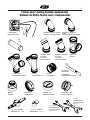
Fusion Lock
®
Joining System: Components
COUPLING
FUSION MACHINE
PIPE
THREADED x SPIGOT 90° ELBOW
THREADED x THREADED 90°
ELBOW
THREADED x SPIGOT
45° ELBOW
THREADED x THREADED
45° ELBOW
SANITARY TEE
45° DOUBLE WYE
45° WYE
REDUCER
LOCKING NUT CLEANOUT PLUG
FUSION LOCK
®
DEPTH GAUGE
3”, 4”, and 6” GROOVER
1-1/2” and 2” GROOVER
3” and 4”
SPANNER WRENCH
1-1/2” and 2”
SPANNER WRENCH
FUSION LOCK™ SEAL
2
Sistema de Unión Fusion Lock
®
: Componentes
APARATO DE FUSIÓN
CODO DE 90° ROSCADO x MACHO CODO DE 90° ROSCADO x ROSCADO
TUBO
CODO DE 45°
ROSCADO x MACHO
CODO DE 45°
ROSCADO x ROSCADO
TUBO EN T
BIFURCACIÓN DOBLE DE 45° BIFURCACIÓN DE 45°
ACOPLAMIENTO
CALIBRADOR DE
PROFUNDIDAD FUSION LOCK
®
REDUCTOR
CONTRATUERCA
REGISTRO DE LIMPIEZA
SELLO FUSION LOCK™
RANURADOR DE 3”, 4” y 6”
RANURADOR DE 1-1/2” y 2”
LLAVE PARA TUERCAS
DE 1-1/2” y 2”
LLAVE PARA TUERCAS
DE 3” y 4”

Fusion Lock
®
Joining System/Sistema de Unión Fusion Lock
®
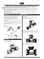
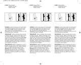
STEP 2/PASO 2
Remove nuts from fittings.
STEP 3/PASO 3
Insert Fusion Lock
®
seal into sockets with leads in the
desired position.
Bend the lead wires inward, and reapply nuts (hand tight).
Bend the leads outward.
PAÑO
ACETONA
RAG
ACETONE
3
STEP 1/PASO 1
Cut pipe square to appropriate length and deburr ends.
Note: Be certain pipe is visibly free of any dirt or debris.
Acetone cleaner may facilitate the cleaning process.
Chop saw or pipe cutting tool will ensure square cuts.
Corte el tubo en ángulo recto del largo adecuado y elimine las rebabas
de ambos extremos.
Nota: Verifique que el tubo esté totalmente libre de polvo o residuos.
Un limpiador a base de acetona puede facilitar el proceso de limpieza.
Usar una sierra de desbastado o una herramienta para cortar tubos
garantiza cortes en ángulo recto.
Retire las tuercas de las conexiones.
Instale el sello Fusion Lock
®
en los receptáculos colocando los
alambres de plomo en la posición deseada.
Doble los alambres de plomo hacia dentro y vuelva a colocar las
tuercas (apriete a mano).
Doble los alambres de plomo hacia afuera.
Note: Pipe, fittings, and seals cannot be stored outdoors or in presence of UV light unless material is shielded as change will occur
and inhibit proper installation. Do not use fusion seals unless they are clear or opaque in color.
Nota: Los tubos, las conexiones y los sellos no deben almacenarse en exteriores o en presencia de rayos UV a menos que el material
esté protegido de la intemperie, ya que pueden ocurrir cambios que impidan una instalación adecuada. No utilice sellos de fusión a
menos que sean transparentes o de color opaco.
Note: At temperatures below 40°F, it is recommended to heat the installation area and allow pipe, fittings, and welder to come to
ambient temperature before fusing.
Nota: A temperaturas inferiores a 40°C, se recomienda para calentar el área de la instalación y permitir que la tubería, accesorios, y el
soldador para llegar a la temperatura ambiente antes de fundirse.

Fusion Lock
®
Joining System/Sistema de Unión Fusion Lock
®
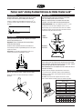
STEP 5/PASO 5
Insert pipe into the joint assembly completely until depth
mark is flush with top of nut.
Important: Failure to insert pipe fully into the fitting
could effect joint integrity.
STEP 6/PASO 6
With the Zurn spanner wrench, tighten nuts until snug.
STEP 8/PASO 8
Press start on the Zurn Fusion Lock
®
machine or on the remote.
Upon completion, press Reset on the machine or remote, remove
the fusion clips and move on to the next joint.
Note: Do not go back and retighten the nuts. Joint must cool 1/2
hour prior to testing.
STEP 4/PASO 4
Hang the Fusion Lock
®
depth gauge (ruler) off the end of
the pipe and mark the pipe according to its diameter.
SINGLE
MULTIPLE
4
STEP 7/PASO 7
Connect the fusion clips to the lead wires on the fusion
seal. For multiple joints connect in a series.
Note: Be certain that there is no undue stress on fusion
lead wire. Use fusion cable velcro strap around pipe to
alleviate this stress.
Cuelgue el calibrador de profundidad (regla) Fusion Lock
®
en
el extremo del tubo y haga una marca en el tubo de acuerdo al
diámetro.
Conecte las pinzas de fusión a los alambres de plomo en el sello
de fusión. En el caso de uniones múltiples conecte en serie.
Nota: Verifique que no exista tensión innecesaria en el alambre
de plomo de fusión. Use una correa velcro para cable de fusión
alrededor del tubo para reducir la tensión.
SENCILLO
MÚLTIPLE
Oprima el botón de arranque del aparato Fusion Lock
®
Zurn o
en el control remoto. Al terminar, oprima el botón Reajustar del
aparato o el control remoto, retire las pinzas de fusión y proceda
a la siguiente unión.
Nota: No retroceda ni vuelva a apretar las tuercas. La unión
debe enfriarse durante media hora antes de realizar las pruebas.
Introduzca el tubo completamente dentro del ensamble de la
unión, hasta que la marca de profundidad quede al ras de la parte
superior de la tuerca.
Importante: El no introducir completamente el tubo en la
conexión puede afectar la integridad de la unión.
Apriete las tuercas con la llave Zurn hasta que estén bien
ajustadas.
Extension Cord Requirements for
Multiple Joint Use
Wire Size Max. Length
(awg.) (ft.)
18 25
16 25
14 50
12 100
10 150
8 250
Multiple Connection Guide
Maximum No. of Joints in Series
Size Ø 1-/2” 2” 3” 4” 6” 8” 10” 12”
Joints 10 8 4 3 2 1 1 1
-
 1
1
-
 2
2
-
 3
3
-
 4
4


Zurn Corrosive Waste Drainage Z9-PLUG-F-2 Guía de instalación
- Tipo
- Guía de instalación
- Este manual también es adecuado para
en otros idiomas
Otros documentos
-
 Prime-Line U 9876 Guía de instalación
-
RIDGID 975 Combo Roll Groover Manual de usuario
-
RIDGID 918-I Roll Groover Manual de usuario
-
-
Orion Couplings Rionfuse CF Guía de instalación
-
Orion SF-PLENUM+-2X1.5-RCPLG Guía de instalación
-
Victor Cutting, Heating and Welding Guide Manual de usuario
-
ProFlo PF1726WH Guía de instalación
-
-
 Tweco TWECO® FUSION™250 Air-Cooled Mig Gun 250 AMP Manual de usuario

