
DS1760-021 LBT21145
Mod.
1760
VIDEO DOOR PHONE 2VOICE HANDS-FREE WiFi
MONITEUR 2VOICE MAIN-LIBRES WiFi
VIDEOINTERFONO 2VOICE MANOS LIBRES WiFi
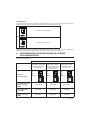
Sch./Ref. 1760/18
(white / blanc / blanco)
Sch./Ref. 1760/19
(black / noire / negro)
INSTALLATION HANDBOOK
NOTICE D’INSTALLATION
MANUAL DE INSTALACIÓN
FCC. ID.: REA176018

2DS1760-021
ENGLISH
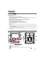
1. DESCRIPTION
The video door phones Ref. 1760/18 and Ref. 1760/19 are dedicated to use in 2Voice video door
phone systems.
The main features are:
5’’ (Wide Angle) TFT-LCD colour screen;
backlit soft-touch buttons (*);
possibility of activating video door phone functions using gesture commands on the IR sensor (disabled
by default);
possibility of adjusting the audio/video (speaker volume, brightness, contrastand colour)in OSD menu;
WVZZPIPSP[`VMJ\Z[VTPZPUN[OLYPUN[VULHJJVYKPUN[V[OLJHSSZV\YJL^P[OHJOVPJLVMÄ]LKPɈLYLU[[`WLZ;
possibility of adjusting the ring tone volume;
call forwarding function to smartphones and tablets;
video door phone answering machine function (up to 32 video messages);
users book for intercom calls (up to 32 users);
“Clean screen” function;
“MUTE” function;
hands-free or push-to-talk mode:
– Hands-free: press the audio button once to start the conversation and once again to end it;
– Push-to-talk: press the audio button to speak to the door unit, release the button to listen.
(*) When a key is pressed an acoustic signal (beep) is provided. This signal is disabled when “MUTE”
function is activated.
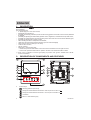
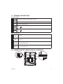
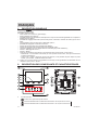
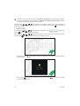
2. DESCRIPTION OF COMPONENTS AND FEATURES
12
13
14
15 1516
12
1
2
3
4
5
6
7
8
10
3
11
9
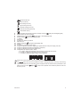
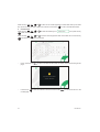
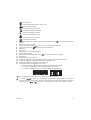
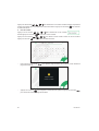
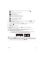
1. Function keys:
: driveway gate door opener key
: closing the contact between terminals X1 and X2 (max 50 mA @ 24 V )
: closing the contact between terminals Y1 and Y2 (max 50 mA @ 24 V )
: no function
: auto-on / video switching key

3
DS1760-021
: special function key
: intercom call key
: left scrolling arrow key
: right scrolling arrow key
: upwards scrolling arrow key
: downwards scrolling arrow key
: switchboard call key
2. Key for activation of secondary functions / display turning on (with green backlighting LED)
3. Raised notches for vision-impaired
4. Pedestrian door opener button (with green / red backlighting LED)
5. Function button (with red backlighting LED)
6. 5” display
7. Microphone
8. IR sensor for gesture commands
9. Micro SD slot
10. (\KPVVUVɈI\[[VU (with green backlighting LED)
11. Speaker
12. Terminals for connecting to the system
13. Jumper for adjustment of power supply type: System BUS or local power supply unit (JP1)
14. Jumper for adjustment of device consumption mode (JP2)
15. Jumper for adjustment of Z line termination (JP3)
16. *VUÄN\YH[PVUKPWZ^P[JOLZ (SW1 / SW2):
– UVVM:>KLÄULZ[OLVWLYH[PUNTVKLVU[OL>P-PVU[OL]PKLVKVVYWOVUL"
– VM:>[VKLÄUL[OLHWHY[TLU[U\TILYPU[OLJVS\TU"
– VM:>[VKLÄUL[OLZ[H[PVUU\TILYPU[OLHWHY[TLU[
SW1 SW2
= =
ON
ON
Refer to the system booklet for how to set the dip switches.
The video door phone is provided with a built-in hearing aid device, which only works during
video calls. Furthermore, the video door phone is equipped with two raised notches, positioned on the
sides next to the buttons and to help vision-impaired users locate the position of the two
buttons by touch.

4DS1760-021
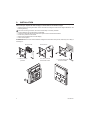
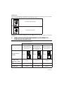
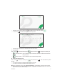
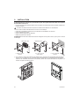
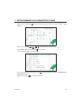
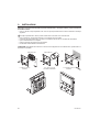
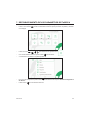
3. INSTALLATION
ATTENTION! For proper operation of the Gesture commands, do not install the device in places
where it may be exposed to direct sunlight, as the IR detector is sensitive to light.
0UZ[HSS[OLÅ\ZOTV\U[PUNIV_4VKVY[OLÅ\ZOTV\U[PUNIV_H[[OLOLPNO[PUKPJH[LKPU[OL
following drawing.
;OLÅ\ZOTV\U[PUNIV_4VKJHUILOVYPaVU[HSS`VY]LY[PJHSS`PUZ[HSSLK
Fix the bracket to the mounting box as indicated.
Program the dip-switches and connect the system wires to the terminal boards.
Fix the door phone to the bracket.
9LTV]L[OLWYV[LJ[P]LÄSTMYVT[OLKPZWSH`
Power on the system.
ATTENTION! )HZLKVU[OLJVS\TUHKKYLZZJVUÄN\YLKVU[OL]PKLVKVVYWOVULZ[OLYLTH`ILHKLSH`PU
switching on.
1,50 m
Box Mod. 503
n° 2 M3,5 x 19 mm
provided n° 2 M3,5 x 19 mm
countersunk screws
Box Ø 60 mm
1,50 m
n° 2 screws and screw
anchors included
1,55 m
2
1

5
DS1760-021
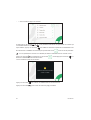
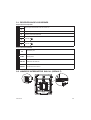
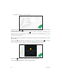
3.1. TERMINAL DESCRIPTION
Left terminal board
V- Terminals for local power supply unit Ref. 1760/110
V+
S- Negative for additional chime
S+ Positive for additional chime
X2
Button
X1
Y2
Button
Y1
Right terminal board
CP Floor call
PANIC Panic alarm
LINE OUT Power supply BUS output
LINE IN Power supply BUS input
3.2. JUMPER AND DIP-SWITCH SW1 NO.1 (DEFAULT)
JP1
JP2
JP3

6DS1760-021
JUMPER (JP3)
The following Jumper allows to adjust the line termination (Z) in case of in-out video door phone connection.
The line termination must be inserted into the last video door phone.
JP3
Termination inserted (default)
Termination not inserted
For position of jumpers JP1 and JP2 and dip-switch SW1 no.1 refer to the next chapter of the following
handbook.
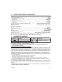
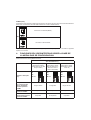
4. VIDEO DOOR PHONE PERFORMANCE ACCORDING TO
CONFIGURATION METHOD
;OL]PKLVKVVYWOVULJHUILJVUÄN\YH[LK^P[OKPɈLYLU[TL[OVKZ+LWLUKPUNVU[OLZLSLJ[LKTL[OVK
limitation will be present on the following performance.
Installation type (*)
Performance Low rise block (Default)
(Power supply from
system BUS with WiFi
always active)
High rise block
(Power supply from
system BUS with
WiFi active after call
forwarding)
Local power
(Power supply from
local power supply unit
Ref. 1760/110)
Jumpers and DIP-
switches
JP1
JP2
SW1 n.1
=
ON
JP1
JP2
SW1 n.1
=
ON
JP1
JP2
SW1 n.1
=
ON
Delay time on
reception of call
forwarding to CallMe
app
No delay 10 seconds No delay
CallMe app auto-on Available Not available Available
Panic alarm signalling
to CallMe App Available Not available Available

7
DS1760-021
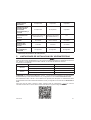
Automatic door
opener timing Not available Available Available
Screen displaying
during intercom
and switchboard calls
Not available Not available Available
Number of video door
phones in riser
Reduction of video door
phone number (*)
Reduction of video
door phone number (*) 127
Display turning on 1 video door phone at a
time in riser
1 video door phone at
a time in riser Unlimited
Display turning on
duration 5 minutes 5 minutes Unlimited
Display timeout time
for inactivity 30 seconds 30 seconds 60 seconds
(*) For the limits of the number of video door entry phone in the riser column, refer to the chapter “Video
door phone installation constraints”.
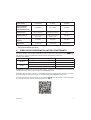
5. VIDEO DOOR PHONE INSTALLATION CONSTRAINTS
0M [OL JVUÄN\YH[PVU TVKL ¸Low rise block” is used on the1760/18 - / 19 video door phones you
can have a reduction in the number of video door phone in a riser column derived from a column distributor
Ref. 1083/53 or a column interface Ref. 1083/50, with the same maximum distances
Reduction is as follows:
Power supply Cable type Number of video door phones
1083/20A 2Voice Ref. 1083/92 - /94 16
CAT5 UTP (one twisted pair) 8
1083/23 2Voice Ref. 1083/92 - /94 5
CAT5 UTP (one twisted pair) 3
ATTENTION! Any Slave video door phones Ref. 1760/18 - /19 present in the apartments must be powered
^P[O [OL SVJHS WV^LY Z\WWS` \UP[ HUK JVUÄN\YLK in Local power mode.
If the video door phone Ref. 1760/18 or /19 is installed as a spare to replace a video door phone, it must be
WV^LYLK [OYV\NO [OL SVJHS WV^LY Z\WWS` HUK JVUÄN\YLK ^P[O [OL Local power mode of use.
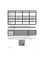
For other types of cables, see the booklet “Limit number of ]PKLVKVVYWOVULZPUYPZLY+:¹
on the Urmet website by scanning the following QR Code.

8DS1760-021
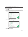
6. CONTACT INSERTION FOR INTERCOM CALLS
In order to make intercom calls, it is necessary to enter contacts in the video door phone book. Up to 32
contacts can be entered.
To enter a new contact, proceed as follows:
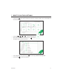
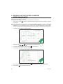
Press the key twice when the video door phone is in stand-by mode to turn on the display and
view the Homepage.
For video door phones powered in High rise block and Low rise block, access to the Homepage is
WLYTP[[LK[VVULKL]PJLH[H[PTLMVYHTH_PT\TVMTPU\[LZ0MH\ZLY[YPLZ[VHJJLZZ[OL/VTLWHNL
when it is already in use on another device, the video door phone will emit a dissuasion tone (4 beeps)
indicating that the page cannot be displayed at the moment.
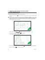
The display shows the following screen:
Press keys , , and to select the following icon .
When selection has been made press the key [VJVUÄYT
The display shows the following screen:
0U[OLJVUÄN\YH[PVUTLU\WYLZZ[OLRL` until selecting “Contacts”.
Press the key [VJVUÄYT[OLZLSLJ[PVU

9
DS1760-021
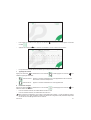
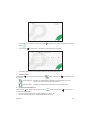
To enter an new contact, press the key and select the icon to add a new contact .
Press the key [VJVUÄYTHUKKPZWSH`[OLMVSSV^PUNZJYLLU!
;OLMVSSV^PUNWHYHTL[LYZT\Z[ILKLÄULKMVYLHJOUL^JVU[HJ[!
1. Contact type
Press the key to select the following icon , then press the key to change the contact type.
External contact: call to a video door phone in another apartment but within the same video
door phone riser
Internal contact: call to a video door phone in the same apartment
2. Video door phone ID code
Press the key to select the following icon , then press the key to enter the video door phone
ID code.
For external contacts, permissible codes range from 0 to 126
For internal contacts, permissible codes range from 0 to 3
0U[OLJVUÄN\YH[PVUTLU\\UKLY¸System information¹P[PZWVZZPISL[V]PL^[OL0+JVKLVM]PKLV
door phones (for more details see the 7HYHTL[LYJVUÄN\YH[PVUOHUKIVVR available by scanning the
QR-Code at the end of the handbook).

10 DS1760-021
Press the keys , , and to select on the virtual keypad the numbers that make up the video
door phone ID code you want to add to the contacts. Press the key [VJVUÄYT[OLZLSLJ[LKU\TILY
3. Contact name
Press the keys , , and to select the following icon , then press the key
to enter the contact name.
Press the keys , , and to use the virtual keypad and enter the contact name. Press the key
[VJVUÄYT[OLJOHYHJ[LYZ[VILLU[LYLK
Finally, press the key to quit the contact insertion page, the display shows the following screen
page:
Press the key to save the contact in the book. Press the key to cancel and return to the
contact page.

11
DS1760-021
7. RESET TO FACTORY SETTINGS
To reset the device to factory settings, proceed as follows:
Press the key twice when the video door phone is in stand-by mode to turn on the display and
view the Homepage.
Press keys , , and to select the following icon .
When selection has been made press the key [VJVUÄYT
The display shows the following screen:
0U[OLJVUÄN\YH[PVUTLU\WYLZZ[OLRL` until selecting “Restore to factory data”.
Press the key [VJVUÄYT[OLZLSLJ[PVU

12 DS1760-021
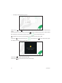
The display shows the following screen:
Press the keys and to select which video door phone parameters you want to reset to factory
values.
When the selection has been made, press the key to enable or disable the parameter for reset to factory
KH[H,UHISPUNPZJVUÄYTLKI`[OLWYLZLUJLVM[OLPJVU next to the parameter name.
By default, all video door phone parameters are enabled for reset to factory data.
Press the key to select the following icon , then press the key to start reset to factory data.
The display shows the following screen page:
Press the key [VJVUÄYTYLZL[[VMHJ[VY`KH[H
Press the key to cancel and return to the previous page.

13
DS1760-021
8. TECHNICAL SPECIFICATIONS
Power voltage (LINE IN): ................................................................................................................36 ÷ 48 V
Power voltage (V+; V-): ............................................................................................................................24 V~
Consumption (LINE IN): ..................................................................................................................... @ 48 V
Stand-by: .......................................................................................................................................... < 3 mA
Full rate: ................................................................................................................................... < 160 mAcc
Consumption (V+; V-): ........................................................................................................................ @ 24 V~
Stand-by: ...................................................................................................................................... < 110 mA
Full rate: ....................................................................................................................................... < 370 mA
Maximum distance from local power supply .....................................................20 m with cable sec. 1 mm2
Frequency band:
WiFi: ........................................................................................................2.4GHz (2412.0 MHz - 2462.0 MHz)
Output power (Max):
WiFi: ..................................................................................................................................................... 20 dBm
Terminals S+ and S- output ....................................................................................................25 mA @ 24V
Display: .........................................................................................................................................5’’ TFT-LCD
Display resolution: ................................................................................................................... 800 x 480 pixel
Operating temperature range: ................................................................................... -5° ÷ 50°C / 23 ÷ 122 °F
Dimensions (LxDxH): .................................................................... 160 x 130 x 26 mm / 0,52 x 0,42 x 0,08 ft
>PYLZ^P[OJYVZZZLJ[PVUHYLHVMTTVYSHYNLYT\Z[JVTWS`^P[O0,*"^PYLZ^P[O
JYVZZZLJ[PVUHYLHZTHSSLY[OHUTTT\Z[JVTWS`^P[O0,*
9. KEY TO SYMBOLS
Symbol Description Symbol Description
Direct input voltage
See the installation manual of
the device
~Alternating input voltage
This device complies with Part 15 of the FCC rules. Operation is subject to the following two
conditions:
1) This device may not cause harmful interference.
2) This device must accept all interference received, including interference that may cause
undesired operation.
15.105 Information to the user statements:
This equipment has been tested and found to comply with the limits for a Class B digital device, pursuant
to part 15 of the FCC Rules. These limits are designed to provide reasonable protection against harmful
interference in a residential installation.
This equipment generates, uses and can radiate radio frequency energy and, if not installed and used in
accordance with the instructions, may cause harmful interference to radio communications. However, there
is no guarantee that interference will not occur in a particular installation.
If this equipment does cause harmful interference to radio or television reception, which can be determined
I`[\YUPUN[OLLX\PWTLU[VɈHUKVU[OL\ZLYPZLUJV\YHNLK[V[Y`[VJVYYLJ[[OLPU[LYMLYLUJLI`VULVYTVYL
of the following measures:
— Reorient or relocate the receiving antenna.
— Increase the separation between the equipment and receiver.
— *VUULJ[[OLLX\PWTLU[PU[VHUV\[SL[VUHJPYJ\P[KPɈLYLU[MYVT[OH[[V^OPJO[OLYLJLP]LYPZJVUULJ[LK
— Consult the dealer or an experienced radio/TV technician for help.
RF exposure warning statement
To comply with FCC RF exposure compliance requirements, a separation distance of at least 20 cm must
be maintained between the antenna of this device and all nearby persons.
*OHUNLZVYTVKPÄJH[PVUZUV[L_WYLZZS`HWWYV]LKI`[OLWHY[`YLZWVUZPISLMVYJVTWSPHUJLJV\SK]VPK
the user’s authority to operate the equipment.

14 DS1760-021
FRANÇAIS
1. DESCRIPTION GÉNÉRALE
Les moniteurs Réf. 1760/18 et Réf. 1760/19 sont dédié à l’utilisation du système 2Voice dans les
systèmes de portiers vidéo.
Principales caractéristiques :
écran couleur TFT-LCD de 5’’ (grand angle) ;
boutons tactiles rétro-éclairé (*);
possibilité d’activer les fonctions du vidéophone au moyen de commandes gestuelles sur le capteur IR
(désactivées par défaut) ;
possibilité de réglage audio/vidéo (volume haut-parleur, luminosité, contraste et couleur) par le menu
OSD ;
WLYZVUUHSPZH[PVUKLSHZVUULYPLLU[YLKPɈtYLU[LZVW[PVUZ"
possibilité de réglage du volume de la sonnerie ;
fonction de renvoi d’appel vers smartphone et tablette ;
fonction de répondeur de moniteur (jusqu’à 32 messages vidéo) ;
répertoire utilisateurs pour les appels intercommunicants (jusqu’à 32 utilisateurs) ;
fonction « Nettoyage de l’écran » ;
fonction « MUTE » ;
mode de conversations mains-libres ou par impulsion de la touche (mode « Push to talk ») :
– Mains-libres : la conversation est activée par une impulsion de la touche, alors qu’une deuxième
impulsion la désactive ;
– Push to talk : quand la touche de phonie est enfoncée, il est possible de parler depuis le poste
PU[LYUL"WV\YtJV\[LYPSZ\ɉ[KLYLSoJOLYSH[V\JOL
(*) L’appui sur un bouton prévoit une signalisation sonore (bip). Cette signalisation est désactivée lors de
l’activation de la fonction « MUTE ».
2. DESCRIPTION DES COMPOSANTS ET CARACTÉRISTIQUES
12
13
14
15 1516
12
1
2
3
4
5
6
7
8
10
3
11
9
1. Touches fonctions :
: touche ouvre-porte de la porte cochère
: fermeture simultanée du contact entre les bornes X1 et X2 (max 50 mA à 24 V )
: fermeture simultanée du contact entre les bornes Y1 et Y2 (max 50 mA à 24 V )

15
DS1760-021
: pas de fonction
: touche activation automatique / renvoi vidéo
: touche fonction spéciale
: touche appel intercommunicant

16 DS1760-021
3. INSTALLATION
ATTENTION ! Pour un fonctionnement correct des commandes gestuelles (Gesture), ne pas installer
le dispositif dans des endroits où il pourrait être exposé aux rayons directs du soleil, car le capteur
IR est sensible à la lumière.
,TT\YLYSLIVz[PLYK»LUJHZ[YLTLU[4VKV\SLIVz[PLYK»LUJHZ[YLTLU[nSHOH\[L\YPUKPX\tLZ\Y
le dessin ci-après.
3LIVz[PLYK»LUJHZ[YLTLU[4VKWL\[v[YLPUZ[HSStOVYPaVU[HSLTLU[V\]LY[PJHSLTLU[
Fixer l’étrier au boîtier d’encastrement ou au mur comme indiqué.
Régler les commutateurs et brancher les conducteurs de l’installation aux borniers.
Fixer le vidéophone à l’étrier.
9L[PYLYSLÄSTKLWYV[LJ[PVUKLS»HɉJOL\Y
Mettez le système sous tension.
ATTENTION!,UMVUJ[PVUKLS»HKYLZZLKLJVSVUULJVUÄN\YtLZ\YSLZWVY[PLYZ]PKtVPSWL\[`H]VPY\UYL[HYK
à l’allumage.
1,50 m (*)
Boîtier Mod. 503
n° 2 M3,5 x 19 mm
de série n° 2 M3,5 x 19 mm
à tête évasée
Boîtier Ø 60 mm
1,50 m (*)
n° 2 vis et chevilles
de série
1,55 m (*)
(*) Pour garantir le respect de la Directive de référence pour les personnes handicapées (par exemple, en
-YHUJL]VPYSH3VPK\SL+tJYL[K\L[ZLZHTLUKLTLU[Z
\S[tYPL\YZKLZL[S»tJYHUK\TVUP[L\YKL]YHv[YLTPZLUWSHJLn\UL
OH\[L\YJVTWYPZLLU[YL L[JT
2
1

17
DS1760-021
3.1. DESCRIPTION DES BORNES
BORNIER GAUCHE
V- Bornes pour alimentateur local Réf. 1760/110
V+
S- Négative pour sonnerie supplémentaire
S+ Positive pour sonnerie supplémentaire
X2
Bouton
X1
Y2
Bouton
Y1
Bornier droit
CP Appel a l’étage
PANIC Alarme de panique
LINE OUT Sortie BUS d’alimentation
LINE IN Entrée BUS d’alimentation
3.2. CAVALIER ET COMMUTATEUR DIP SW1 N.1 (DÉFAUT)
JP1
JP2
JP3

18 DS1760-021
CAVALIER (JP3)
Le cavalier suivant permet le réglage de la terminaison de ligne (Z) en cas de connexion du moniteur en
mode entrée-sortie. La terminaison de ligne doit être insérée sur le dernier moniteur.
JP3
Terminaison insérée (défaut)
Terminaison non insérée
Le cavalier suivant permet le réglage de la terminaison de ligne (Z) en cas de connexion du moniteur en
mode entrée-sortie. La terminaison de ligne doit être insérée sur le dernier moniteur.
4. PERFORMANCES DU MONITEUR SELON LE MODE
DE CONFIGURATION
3L TVUP[L\Y WL\[ v[YL JVUÄN\Yt LU TVKLZ KPɈtYLU[Z :LSVU SL TVKL ZtSLJ[PVUUt SLZ WLYMVYTHUJLZ
suivantes seront limitées.
Type d’installation (*)
Performances Standard (Default)
(Alimentation depuis BUS
de système avec WiFi
toujours actif)
Restreint
(Alimentation depuis
BUS de système avec
WiFi actif suite à un
renvoi d’appel)
Confort
(Alimentation depuis
alimentateur local
Réf. 1760/110)
Cavalier et
commutateur DIP
JP1
JP2
SW1 n.1
=
ON
JP1
JP2
SW1 n.1
=
ON
JP1
JP2
SW1 n.1
=
ON
Temps de retard sur
la réception du renvoi
d’appel vers l’App
CallMe
Aucun retard 10 secondes Aucun retard
Activation
automatique depuis
l’App CallMe Disponible Indisponible Disponible
Signalisation d’alarme
panique vers l’App
CallMe Disponible Indisponible Disponible

19
DS1760-021
Temporisation ouvre-
porte automatique Indisponible Disponible Disponible
(ɉJOHNLKLZ
pages-écrans pendant
les appels
intercommunicants et
à la centrale
Indisponible Indisponible Disponible
Nombre de moniteurs
en colonne Réduction du nombre de
moniteurs (*)
Réduction du nombre
de moniteurs (*) 127
Allumage de l’écran 1 moniteur à la fois en
colonne
1 moniteur à la fois en
colonne Sans limites
Durée de l’allumage
de l’écran 5 minutes 5 minutes Sans limites
Temps de
dépassement de
l’écran suite à
inactivité
30 secondes 30 secondes 60 secondes
(*) Pour les limites du nombre de moniteurs en colonne installés, se référer au chapitre « Obligations
K»PUZ[HSSH[PVUK\TVUP[L\Y ».
5. OBLIGATIONS D’INSTALLATION DU MONITEUR
Si sur le moniteur Réf. 1760/18 - /19 le mode d’utilisation est utilisé “Standard”, il est possible
d’avoir une réduction du nombre de moniteur dans une colonne montante dérivée d’un répartiteur colonne
Réf. 1083/53 ou une interface colonne Réf. 1083/50, avec les mêmes distances maximales.
La réduction est la suivante:
Alimentation Type de câble Nombre de moniteurs
1083/20A 2Voice Réf. 1083/92 - /94 16
CAT5 UTP (une paire torsadée) 8
1083/23 2Voice Réf. 1083/92 - /94 5
CAT5 UTP (une paire torsadée) 3
ATTENTION ! Tout moniteur Esclave Réf. 1760/18 - /19 installé dans les appartements doit être
HSPTLU[t WHY S»HSPTLU[H[L\Y SVJHS L[ JVUÄN\Yt ZLSVU SL TVKL KL JVUÄN\YH[PVU Confort.
Si le moniteur Réf. 1760/18 ou /19 s’installe en rechange en remplacement d’une moniteur il doit être
HSPTLU[t WHY S»HSPTLU[H[PVU SVJHSL L[ JVUÄN\Yt H]LJ SL TVKL K»\[PSPZH[PVU Confort.
7V\YSLZH\[YLZ[`WLZKLJoISLZJVUZ\S[LaSLSP]YL[3PTP[LYSLUVTIYLKLTVUP[L\Y dans la colonne
TVU[HU[L+:® sur le site Urmet en scannant le QR Code suivant.

20 DS1760-021
6. INSERTION DES CONTACTS POUR APPELS
INTERCOMMUNICANTS
7V\YLɈLJ[\LYKLZHWWLSZPU[LYJVTT\UPJHU[ZPSMH\[PUZtYLYKLZJVU[HJ[ZKHUZSLYtWLY[VPYLK\TVUP[L\Y0S
est possible d’insérer jusqu’à 32 contacts.
Pour insérer un nouveau contact, suivre la procédure ci-dessous :
Appuyer 2 fois sur la touche avec le moniteur au repos pour allumer l’écran et visualiser la page
d’accueil.
7V\Y SLZ TVUP[L\YZ JVUÄN\YtZ H]LJ SL TVKL K»\[PSPZH[PVU Restreint et Standard, l’accès à la page
K»HJJ\LPSU»LZ[H\[VYPZtX\»n\UZL\SKPZWVZP[PMnSHMVPZWV\Y\ULK\YtLTH_PTHSLKLTPU\[LZ:P\U
utilisateur essaie d’accéder à la page d’accueil utilisée par un autre dispositif, le moniteur émet une
tonalité de dissuasion (4 bips) pour indiquer que l’accès à la page est temporairement impossible.
L’écran visualise la page-écran suivante :
Appuyer sur les touches , , et pour sélectionner l’icône suivante .
Après sélection, appuyer sur la touche WV\YJVUÄYTLY
L’écran visualise la page-écran suivante :
+HUZSLTLU\KLJVUÄN\YH[PVUHWW\`LYZ\YSH[V\JOL jusqu’à la sélection de l’option « Contacts ».
Appuyer sur la touche WV\YJVUÄYTLYSHZtSLJ[PVU

21
DS1760-021
Pour insérer un nouveau contact, appuyer sur la touche et sélectionner l’icône d’ajout d’un nouveau
contact .
Appuyer sur la touche WV\YJVUÄYTLYL[]PZ\HSPZLYnS»tJYHUSHWHNLtJYHUZ\P]HU[L!
3LZWHYHTu[YLZZ\P]HU[ZKVP]LU[v[YLKtÄUPZWV\YJOHX\LUV\]LH\JVU[HJ[!
1. Typologie de contact
Appuyer sur la touche pour sélectionner l’icône suivante , ensuite appuyer sur la touche pour
TVKPÄLYSH[`WVSVNPLKLJVU[HJ[
Contact externe : appel à un moniteur installé dans un autre appartement mais à l’intérieur
de la même colonne de vidéophonie
Contact interne : appel à un moniteur installé dans le même appartement
2. Code ID du moniteur
Appuyer sur la touche pour sélectionner l’icône suivante , ensuite appuyer sur la touche pour
insérer le code ID du moniteur.
Pour les contacts externes, les codes admis sont de 0 à 126.
Pour les contacts internes, les codes admis sont de 0 à 3.
+HUZSLTLU\KLJVUÄN\YH[PVUZV\ZS»VW[PVU0UMVYTH[PVUZKLZ`Z[uTL®VUWL\[]PZ\HSPZLYSLJVKL0+
KLZTVUP[L\YZWV\YWS\ZKLKt[HPSZZLYtMtYLYH\4HU\LSKLJVUÄN\YH[PVUKLZWHYHTu[YLZKPZWVUPISL
LUZJHUUHU[SLJVKL89ÄN\YHU[nSHÄUK\THU\LS

22 DS1760-021
Appuyer sur les touches , , et WV\YZtSLJ[PVUULYZ\YSLJSH]PLY]PY[\LSSLZJOPɈYLZJVTWVZHU[SL
code ID du moniteur que l’on souhaite insérer dans les contacts. Appuyer sur la touche WV\YJVUÄYTLY
SLJOPɈYLZtSLJ[PVUUt
3. Nom du contact
Appuyer sur les touches , , et pour sélectionner l’icône suivante ,
ensuite appuyer sur la touche pour insérer le nom du contact.
Appuyer sur les touches , , et pour utiliser le clavier virtuel et insérer le nom du contact.
Appuyer sur la touch WV\YJVUÄYTLYSLZJHYHJ[uYLZnZHPZPY
,UÄUHWW\`LYZ\YSH[V\JOL pour quitter la page d’insertion des contacts, l’écran visualise la
page-écran suivante :
Appuyer sur la touche pour enregistrer le contact dans le répertoire. Appuyer sur la touche
pour annuler et revenir à la page des contacts.

23
DS1760-021
7. RÉTABLISSEMENT AUX PARAMÈTRES D’USINE
Pour le rétablissement du dispositif aux paramètres d’usine, suivre la procédure ci-dessous :
Appuyer 2 fois sur la touche avec le moniteur au repos pour allumer l’écran et visualiser la page
d’accueil.
Appuyer sur les touches , , et pour sélectionner l’icône suivante .
Après sélection, appuyer sur la touche WV\YJVUÄYTLY
L’écran visualise la page-écran suivante :
+HUZSLTLU\KLJVUÄN\YH[PVUHWW\`LYZ\YSH jusqu’à la sélection de l’option « Rétablissement
aux données d’usine ».
Appuyer sur la touche WV\YJVUÄYTLYSHZtSLJ[PVU

24 DS1760-021
L’écran visualise la page-écran suivante :
En appuyant sur les touches et il est possible de sélectionner les paramètres du moniteur que
l’on souhaite rétablir aux valeurs d’usine.
Après sélection, appuyer sur la touche pour habiliter ou désactiver le paramètre au rétablissement aux
KVUUtLZK»\ZPUL3»OHIPSP[H[PVULZ[JVUÄYTtLWHYSHWYtZLUJLKLS»PJUL à côté du nom du paramètre.
Tous les paramètres du moniteur sont habilités par défaut au rétablissement aux données d’usine.
Appuyer sur la touche pour sélectionner l’icône suivante , ensuite appuyer sur la touche pour
démarrer le rétablissement aux données d’usine.
L’écran visualisera la page-écran suivante :
Appuyer sur la touche WV\YJVUÄYTLYSLYt[HISPZZLTLU[H\_KVUUtLZK»\ZPUL
Appuyer sur la touche pour annuler et revenir à la page précédente.

25
DS1760-021
8. CARACTÉRISTIQUES TECHNIQUES
Tension d’alimentation (LINE IN): ...................................................................................................36 ÷ 48 V
Tension d’alimentation (V+; V-): ..............................................................................................................24 V~
Consommation Maximum (LINE IN): ................................................................................................. @ 48 V
Au repos: .......................................................................................................................................... < 3 mA
A plein régime: ......................................................................................................................... < 160 mAcc
Consommation Maximum (V+; V-): .................................................................................................... @ 24 V~
Au repos: ...................................................................................................................................... < 110 mA
A plein régime: ............................................................................................................................. < 370 mA
Distance maximale de l’alimentation électrique locale : ........................ 20 m avec section de câble 1 mm2
Bande de fréquence:
WiFi: ........................................................................................................2.4GHz (2412.0 MHz - 2462.0 MHz)
Puissance de sortie (Max):
WiFi: ..................................................................................................................................................... 20 dBm
Sortie des bornes S+, S-: ........................................................................................................ 25 mA @ 24V
Écran: ...........................................................................................................................................5’’ TFT-LCD
Résolution écran: ....................................................................................................................800 X 480 pixel
Température de fonctionnement: .............................................................................. -5° ÷ 50°C / 23 ÷ 122 °F
Dimensions (L x H x P): ................................................................. 160 x 130 x 26 mm / 0,52 x 0,42 x 0,08 ft
3LZJoISLZ\[PSPZtZKVP]LU[ZH[PZMHPYLSHUVYTL0,*ZPSHZLJ[PVUTLZ\YLH\TVPUZ
TTV\SHUVYTL0,*ZPSHZLJ[PVUTLZ\YLTVPUZKLTT.
9. LÉGENDES SYMBOLES
Symbole Explication Symbole Explication
Tension d’alimentation continue
Se reporter au manuel
d’installation du dispositif
~Tension d’alimentation alternée
Le dispositif est conforme à la Partie 15 des normes FCC sujettes aux deux conditions suivantes:
1) Le dispositif ne doit pas causer d’interférences nocives.
2) Le dispositif doit supporter toutes les interférences reçues, y compris celles qui peuvent causer
un fonctionnement indésirable.
15.105 Informations sur les déclarations utilisateur:
L’appareillage a été testé et sa conformité aux limites pour les dispositifs numériques de Classe B a été
attestée, conformément à la partie 15 des normes FCC. Ces limites sont établies pour fournir une protection
raisonnable contre les interférences dangereuses sur une installation résidentielle. L’appareillage génère,
utilise et peut irradier de l’énergie en radio fréquence et, dans le cas où il ne serait pas installé et/ou utilisé
conformément aux instructions, il peut causer des interférences dangereuses pour les communications radio.
Toutefois, aucune garantie n’est fournie quant à l’éventualité d’interférences sur une installation donnée.
Si l’appareillage cause des interférences dangereuses pour la réception radio ou TV, qui peuvent intervenir
en éteignant et en rallumant l’appareillage, l’utilisateur est invité à corriger l’interférence en recourant à une
des solutions suivantes :
— 6YPLU[LYKPɈtYLTTLU[V\YLWVZP[PVUULYS»HU[LUULK\YtJLW[L\Y
— Augmenter la distance entre l’appareillage et le récepteur.
— Brancher l’appareillage à une prise d’un circuit autre que celui auquel le récepteur est branché.
— *VUZ\S[LYSLJVUJLZZPVUUHPYLV\\U[LJOUPJPLUYHKPV;=X\HSPÄtWV\YVI[LUPYS»HZZPZ[HUJLUtJLZZHPYL
Déclaration d’avertissement pour l’exposition aux RF
(ÄUKLYLZWLJ[LYSLZZ[HUKHYKZYLX\PZKL JVUMVYTP[t-**WV\YS»L_WVZP[PVUH\_ 9-PSLZ[UtJLZZHPYLKL
maintenir une distance d’au moins 20 cm entre l’antenne du dispositif et toutes les personnes présentes à
proximité.
;V\[LTVKPÄJH[PVUUVUL_WYLZZtTLU[HWWYV\]tLWHYSLYLZWVUZHISLKLSHJVUMVYTP[tWL\[PU]HSPKLY
le droit de l’utilisateur à utiliser l’appareillage.

26 DS1760-021
ESPAÑOL
1. DESCRIPCIÓN
Los videointerfonos Ref. 1760/18 y Ref. 1760/19 han sido diseñados para el uso en sistemas de
videointerfono 2Voice.
Las características principales son:
The main features are:
pantalla en color TFT-LCD de 5’’ (Wide Angle);
pulsadores sensibles al tacto iluminados en la cara posterior (*);
posibilidad de activaciones de las funciones del videointerfonos mediante mandos gestuales del sensor
IR (por defecto inactivadas);
posibilidad de regulación vídeo (contraste, brillo y color) mediante menú OSD;
posibilidad de personalizar el timbre escogiendo entre 5 tipos diferentes;
posibilidad de regulación del volumen del timbre;
función de desvío de llamada a smartphone y tableta;
función de mensajería videointerfono (hasta 32 videomensajes);
guía de usuarios para llamadas intercomunicantes (hasta 32 usuarios);
función de “Limpiar pantalla”;
función “MUTE”;
Modo de conversación en manos libres o mediante el accionamiento del pulsador (modo “Push to
talk”):
– Manos libres: accionando el pulsador de fonía se activa la conversación y, accionándolo una segunda
vez, ésta se desactiva;
– Push to talk: desde el aparato interior, manteniendo accionado el pulsador de fonía se puede hablar,
mientras que soltando el pulsador se puede escuchar.
(*) Tras la presión de un pulsador se generará una señal acústica (bip). Esta señal se inhibe cuando se activa
la función “MUTE”.
2. DESCRIPCIÓN DE LOS COMPONENTES Y CARACTERÍSTICAS
12
13
14
15 1516
12
1
2
3
4
5
6
7
8
10
3
11
9
1. Teclas función:
: apertura cancela de acceso
: cierre del contacto presente entre los bornes X1 y X2 (max 50 mA @ 24 V )

27
DS1760-021
: cierre del contacto presente entre los bornes Y1 y Y2 (max 50 mA @ 24 V )
: sin función
: tecla autoencendido / transferencia vídeo
: tecla función especial
: tecla llamada intercomunicante
![LJSHÅLJOHKLZWSHaHTPLU[VOHJPHSHPaX\PLYKH
![LJSHÅLJOHKLZWSHaHTPLU[VOHJPHSHKLYLJOH
![LJSHÅLJOHKLZWSHaHTPLU[VOHJPHHYYPIH
![LJSHÅLJOHKLZWSHaHTPLU[VOHJPHHIHQV
: tecla llamada a la central
2. Tecla para la activación de las funciones secundarias / encendido de la pantalla (con led verde
de etroiluminación)
3. Muescas en relieve por usuarios ciegos
4. Pulsador de apertura de la puerta para peatones (con led verde / rojo de retroiluminación)
5. Tecla función : función “MUTE” (con led rojo de retroiluminación)
6. Pantalla 5”
7. Micrófono
8. Sensor IR para mandos gestuales
9. Ranura micro SD
10. Tecla de activación/desactivación de la fonía (con led verde de retroiluminación)
11. Altavoz
12. Bornes para la conexión al sistema
13. Jumper para el ajuste del tipo de alimentación: BUS de sistema o alimentador local (JP1)
14. Jumper para el ajuste de la modalidad de consumo del dispositivo (JP2)
15. Jumper para el ajuste de la terminación de línea Z (JP3)
16. 0U[LYY\W[VYKPWKLJVUÄN\YHJP}U":>:>!
– UYKL:>KLÄULSHTVKHSPKHKKLM\UJPVUHTPLU[VKLS>P-PWYLZLU[LLULS]PKLVPU[LYMVUVZ"
– UYKLHKL:>KLÄULULSUTLYVKLSHWHY[HTLU[VLUSHJVS\TUH"
– UY`KL:>KLÄULULSUTLYVKLSHWHYH[VPU[LYPVYKLU[YVKLSHWHY[HTLU[V
SW1 SW2
= =
ON
ON
7HYHSHZJVUÄN\YHJPVULZKLSVZPU[LYY\W[VYLZKPWJVUZ\S[HYLSTHU\HSKLZPZ[LTH
El videointerfono [PLULPUJVYWVYHKV\UKPZWVZP[P]VWHYHWLYZVUHZJVUKtÄJP[H\KP[P]VX\LZ}SV
funciona durante las llamadas videointerfónicas. Además, el videointerfono tiene dos muescas en relieve,
colocadas a los lados, en coincidencia con los botones y , para permitir que los usuarios
ciegos encuentren al tacto la posición de los dos pulsadores.

28 DS1760-021
3. INSTALACIÓN
¡ATENCIÓN! Para un funcionamiento correcto de los mandos gestuales (Gesture), no instalar el
dispositivo en lugares donde quede expuesto directamente a los rayos solares, ya que el sensor IR
es sensible a la luz.
-PQHYHSHWHYLKSHJHQHLTWV[YHKHTVKVSHJHQHLTWV[YHKHHSHHS[\YHPUKPJHKHLULSKPI\QV
siguiente.
La caja empotradH4VKZLW\LKLPUZ[HSHY[HU[VOVYPaVU[HSJVTV]LY[PJHSTLU[L
Fijar el soporte en la caja para empotrar o en la pared, según se indica.
Programar los interruptores dip y conectar a los tableros de bornes los conductores del sistema.
Fijar el videointerfono en el soporte.
Retirar la película de protección de la pantalla.
Encienda el sistema desde la red eléctrica.
¡ATENCIÓN! +LWLUKPLUKVKLSHKPYLJJP}UKLJVS\TUHJVUÄN\YHKHLUSVZ]PKLVPU[LYMVUVW\LKLOHILY\U
retrasoen el encendido.
1,50 m
Caja Mod. 503
n° 2 M3,5 x 19 mm
incluidos
n° 2 M3,5 x 19 mm
de cabeza avellanada
Caja Ø 60 mm
1,50 m
n° 2 tornillos y tacos
incluidos
1,55 m
2
1

29
DS1760-021
3.1. DESCRIPCIÓN DE LOS BORNES
Regleta de bornes izquierda
V- Bornes para alimentador local Ref. 1760/110
V+
S- Negativo para timbre adicional
S+ Positivo para timbre adicional
X2
Pulsador
X1
Y2
Pulsador
Y1
Regleta de bornes derecha
CP Llamada al piso
PANIC Alarma pánico
LINE OUT Salida BUS alimentación
LINE IN Entrada BUS alimentación
3.2. JUMPER E INTERRUPTOR SW1 N.1 (DEFAULT)
JP1
JP2
JP3

30 DS1760-021
JUMPER (JP3)
El siguiente Jumper permite el ajuste de la terminación de línea (Z) en caso de conexión del videointerfonos
entrar-salir. La terminación de línea debe instalarse en el último videointerfonos.
JP3
Terminación conectada (default)
Terminación desconectada
Con relación a la posición de los jumper JP1 y JP2 y del interruptor dip SW1 n.1 consultar el siguiente
capítulo en el manual.
4. FUNCIONES DEL VIDEOINTERFONO SOBRE LA BASE DE
LA MODALIDAD DE CONFIGURACIÓN
,S]PKLVPU[LYMVUVZW\LKLJVUÄN\YHYKLTVKVZKPMLYLU[LZ+LWLUKPLUKVKLSHTVKHSPKHKZLSLJJPVUHKH
habrá limitaciones en las siguientes funciones.
Tipo de instalación (*)
Funciones ,KPÄJPV+LMH\S[
(Alimentación desde
BUS de sistema con WiFi
siempre activo)
Condominio
(Alimentación desde
BUS de sistema con
WiFi activo tras un
desvío de llamada)
Alimentación local
(Alimentación desde
alimentador local Ref.
1760/110)
Jumper e interruptor
dip
JP1
JP2
SW1 n.1
=
ON
JP1
JP2
SW1 n.1
=
ON
JP1
JP2
SW1 n.1
=
ON
Tiempo de retraso
en la recepción del
desvío de llamada
hacia la aplicación
CallMe
Ningún retraso 10 segundos Ningún retraso
Autoencendido de la
aplicación CallMe Disponible No disponible Disponible
Señalización de
alarma pánico hacia la
aplicación CallMe Disponible No disponible Disponible

31
DS1760-021
Temporización
apertura puerta
automática No disponible Disponible Disponible
Visualización de las
pantallas durante
las llamadas
intercomunicante y a
la central
No disponible No disponible Disponible
Número de
videointerfonos en
columna
Reducción del número de
videointerfonos (*)
Reducción del número
de videointerfonos (*) 127
Encendido de la
pantalla
1 videointerfonos a la vez
en columna
1 videointerfonos a la
vez en columna Sin límites
Duración de la
activación de la
pantalla 5 minutos 5 minutos Sin límites
Tiempo de timeout
de la pantalla por
inactividad 30 segundos 30 segundos 60 segundos
7HYH SVZ SxTP[LZ KLS UTLYV KL ]PKLVPU[LYMVUVZ LU JVS\TUH TVU[HU[L JVUZ\S[HY LS JHWx[\SV ,KPÄJPV
“Limitaciones de instalación del videointerfono”.
5. LIMITACIONES DE INSTALACIÓN DEL VIDEOINTERFONO
:P ZL \[PSPaH LS TVKV KL \ZV ¸,KPÄJPV¹ LU SVZ ]PKLVWVY[LYVZ 1760/18 - /19 se puede tener una
reducción del número de videinterfono en una columna montante derivado de un distribuidor de columna
Ref. 1083/53 o una interfaz de columna Ref. 1083/50, con las mismas distancias máximas.
La reducción es la siguiente:
Alimentador Tipo de cable Número de videointerfonos
1083/20A 2Voice Ref. 1083/92 - /94 16
CAT5 UTP (un par enredado) 8
1083/23 2Voice Ref. 1083/92 - /94 5
CAT5 UTP (un par enredado) 3
¡ATENCIÓN! Los videointerfonos Slave Ref. 1760/18 - /19 que estuvieran instalados en los pisos deberán
ZLY HSPTLU[HKVZ WVY TLKPV KL HSPTLU[HKVY SVJHS ` JVUÄN\YHKVZ JVU SH TVKHSPKHK Alimentación local.
Si le videointerfono Ref. 1760/18 o /19 se instala como repuesto para reemplazar un videointerfono debe
ZLY HSPTLU[HKV H [YH]tZ KL SH M\LU[L KL HSPTLU[HJP}U SVJHS ` JVUÄN\YHKV JVU LS TVKV KL \ZV Alimentación
local.
Para otros tipos de cables, consulte el folleto “Número límite de videointerfono en columna
TVU[HU[L+:¹LULSZP[PV^LIKL<YTL[LZJHULHUKVLSZPN\PLU[LJ}KPNV89

32 DS1760-021
6. AGREGAR CONTACTOS PARA LLAMADAS
INTERCOMUNICANTES
Para poder realizar llamadas intercomunicantes es necesario agregar los contactos en la guía videointerfono.
Se pueden agregar hasta 32 contactos.
Para introducir un contacto nuevo, seguir el procedimiento a continuación:
Pulsar 2 veces la tecla cuando el videointerfono está en reposo para activar la pantalla y visualizar
a Homepage.
Para los videointerfonos alimentados en modalidad Condominio y ,KPÄJPV, el acceso a la Homepage
ZL WLYTP[L ZVSV H \U KPZWVZP[P]V H SH ]La K\YHU[L \U [PLTWV Tm_PTV KL TPU\[VZ :P \U \Z\HYPV
PU[LU[HYHHJJLKLY HSH /VTLWHNLJ\HUKVV[YV KPZWVZP[P]V`HSH LZ[m]PZ\HSPaHUKV LS]PKLVPU[LYMVUV
emitirá un tono de disuasión (4 bips) para indicar que no es posible al momento acceder a la página.
A continuación se muestra la siguiente pantalla:
Pulsar las teclas , , y para seleccionar el siguiente icono .
Una vez efectuada la selección pulsar la tecla WHYHJVUÄYTHY
A continuación se muestra la siguiente pantalla:
,ULSTLUKLJVUÄN\YHJP}UWYLZPVUHYSH[LJSH hasta seleccionar la opción “Contactos”.
Pulsar la tecla WHYHJVUÄYTHYSHZLSLJJP}U

33
DS1760-021
Para introducir un contacto nuevo pulsar la tecla y seleccionar el icono para agregar un contacto
nuevo .
Pulsar la tecla WHYHJVUÄYTHY`]PZ\HSPaHYSHZPN\PLU[LWmNPUHLUSHWHU[HSSH!
Para cada contacto nuevo es necesario introducir los siguientes parámetros:
1. Tipo de contacto
Pulsar la tecla para seleccionar el siguiente icono , luego pulsar la tecla para cambiar el tipo
de contacto.
Contacto externo: llamada a un videointerfono presente en otro apartamento pero en el
interior de la misma columna de videointerfonos
Contacto interno: llamada a un videointerfono presente en el mismo apartamento
2. Código ID del videointerfono
Pulsar la tecla para seleccionar el siguiente icono , luego pulsar la tecla para introducir el
código ID del videointerfono.
Para los contacto externos los códigos admitidos son de 0 a 126
Para los contacto internos los códigos admitidos son de 0 a 3

34 DS1760-021
,ULSTLUKLJVUÄN\YHJP}ULUSHVWJP}U¸Información de sistema¹LZWVZPISL]PZ\HSPaHYLSJ}KPNV
0+KLSVZ]PKLVPU[LYMVUVZWHYHTmZKL[HSSLZ]LYLS4HU\HSKLJVUÄN\YHJP}UWHYmTL[YVZ disponible
LZJHULHUKVLSJ}KPNV89WYLZLU[LHSÄUHSKLSTHU\HS
Pulsar las teclas , , y para seleccionar en el teclado virtual los números que componen el
código ID del videointerfono que se desea agregar a los contactos. Pulsar la tecla WHYHJVUÄYTHYLS
número seleccionado.
3. Nombre contacto
Pulsar las teclas , , y para seleccionar el siguiente icono , luego pulsar
la tecla para introducir el nombre del contacto.
Pulsar las teclas , , y para utilizar el teclado virtual e introducir el nombre del contacto.
Pulsar la tecla WHYHJVUÄYTHYSVZJHYHJ[LYLZX\LZLKLZLHUPU[YVK\JPY
(SÄUHSW\SZHYSH[LJSH para salir de la página de introducción contactos, la pantalla visualiza la
siguiente página:
Pulsar la tecla para guardar el contacto en la guía. Pulsar la tecla para cancelar y regresar
a la página de los contactos.

35
DS1760-021
7. RESTABLECIMIENTO DE LOS PARÁMETROS DE FÁBRICA
Para restablecer el dispositivo a los parámetros de fábrica, seguir el siguiente procedimiento:
Pulsar 2 veces la tecla cuando el videointerfono está en reposo para activar la pantalla y visualizar
a Homepage.
Pulsar las teclas , , y para seleccionar el siguiente icono .
Una vez efectuada la selección pulsar la tecla WHYHJVUÄYTHY
A continuación se muestra la siguiente pantalla:
,ULSTLUKLJVUÄN\YHJP}UW\SZHYSH[LJSH hasta seleccionar la opción “9LZH\YHYJVUÄN\YHJP}U
de fábrica”.
Pulsar la tecla WHYHJVUÄYTHYSHZLSLJJP}U

36 DS1760-021
A continuación se muestra la siguiente pantalla:
Pulsando las teclas y es posible seleccionar los parámetros del videointerfono que se desea
restablecer a los valores de fábrica.
Una vez realizada la selección pulsar la tecla para habilitar o deshabilitar el parámetro para el
YLZ[HISLJPTPLU[VHSVZKH[VZKLMmIYPJH3HOHIPSP[HJP}UZLJVUÄYTHJVUSHWYLZLUJPHKLSPJVUV al
lado del nombre del parámetro.
Por defecto todos los parámetros del videointerfono se habilitan para el restablecimiento a los datos
de fábrica.
Pulsar la tecla para seleccionar el siguiente icono , luego pulsar la tecla para iniciar el
restablecimiento de los datos de fábrica. A continuación se muestra la siguiente pantalla:
Pulsar la tecla WHYHJVUÄYTHYLSYLZ[HISLJPTPLU[VHSVZKH[VZKLMmIYPJH
Pulsar la tecla para cancelar y regresar a la página anterior.

37
DS1760-021
8. CARACTERÍSTICAS TÉCNICAS
Tensión de alimentación (LINE IN): ................................................................................................36 ÷ 48 V
Tensión de alimentación (V+; V-): ............................................................................................................24 V~
Absorción (LINE IN): .......................................................................................................................... @ 48 V
Stand-by: .......................................................................................................................................... < 3 mA
Full rate: ................................................................................................................................... < 160 mAcc
Absorción (V+; V-): ............................................................................................................................. @ 24 V~
Stand-by: ...................................................................................................................................... < 110 mA
Full rate: ....................................................................................................................................... < 370 mA
Distancia máxima alimentador local:....................................................................20 m con cavo sez. 1 mm2
Banda de frecuencia:
WiFi: ........................................................................................................2.4GHz (2412.0 MHz - 2462.0 MHz)
Potencia de salida (máx.):
WiFi: ..................................................................................................................................................... 20 dBm
Salida bornes S+, S-:............................................................................................................... 25 mA @ 24V
Pantalla: ........................................................................................................................................5’’ TFT-LCD
Resolución de la pantalla: .......................................................................................................800 X 480 pixel
Temperatura de funcionamiento: .............................................................................. -5° ÷ 50°C / 23 ÷ 122 °F
Dimensiones (AxFxA): ................................................................... 160 x 130 x 26 mm / 0,52 x 0,42 x 0,08 ft
3VZJHISLZ\[PSPaHKVZKLILUYLZWVUKLYHSHUVYTH0,*ZP[PLULU\UHZLJJP}UKL
mmVZ\WLYPVYVHSHUVYTH0,*ZPSHZLJJP}ULZPUMLYPVYHTT.
9. LEYENDA DE LOS SÍMBOLOS
Símbolo Explicación Símbolo Explicación
Tensión de alimentación continua
Consulte el manual de
instalación del dispositivo
~Tensión de alimentación alterno
Este dispositivo cumple con el Apartado 15 de las normas de FCC relacionadas con las siguientes
dos condiciones:
1) Este dispositivo no puede causar interferencia dañina.
2) Este dispositivo debe aceptar toda interferencia recibida, incluyendo la interferencia que pueda
causar un funcionamiento no deseado.
15.105 Información a las declaraciones de usuario :
Este equipo ha sido sometido a las pruebas pertinentes y cumple con los límites establecidos para un
dispositivo digital de Clase B, conforme al apartado 15 de las reglas de la FCC.
Estos límites están diseñados para proporcionar una protección razonable contra la interferencia dañina
en una instalación residencial. Este equipo genera, utiliza y puede irradiar energía de radiofrecuencia y si
no se instala y utiliza de acuerdo con las instrucciones, puede causar interferencias perjudiciales en las
comunicaciones de radio. Sin embargo, no hay garantía de que no se vaya a producir interferencia en una
PUZ[HSHJP}ULULZWLJxÄJV:PLZ[LLX\PWVJH\ZHPU[LYMLYLUJPHWLYQ\KPJPHSHSHYLJLWJP}UKLYHKPVV[LSL]PZP}U
puede determinarla prendiendo y apagando el equipo, se recomienda al usuario que intente corregir la
interferencia realizando una o más de las siguientes medidas:
— Cambie la orientación o ubicación de la antena receptora.
— Aumente la distancia entre el equipo y el receptor.
— Conecte el equipo a la toma corriente en un circuito distinto al que esté conectado el receptor.
— Consulte al distribuidor o a un técnico de radio y TV con experiencia.
Aviso de advertencia de la exposición de RF
Para seguir los requisitos de conformidad de exposición a las RF de la FCC, se debe mantener la distancia
de separación de al menos 20 cm entre la antena de este dispositivo y todas las personas cercanas.
3VZJHTIPVZVTVKPÄJHJPVULZUVHWYVIHKVZL_WYLZHTLU[LWVYSHWHY[LYLZWVUZHISLKLSJ\TWSPTPLU[V
pueden anular la autoridad del usuario para utilizar el equipo.

38 DS1760-021
ENGLISH
DIRECTIVE 2012/19/EU OF THE EUROPEAN PARLIAMENT AND OF THE COUNCIL of 4
July 2012 on waste electrical and electronic equipment (WEEE)
The symbol of the crossed-out wheeled bin on the product or on its packaging indicates that this
product must not be disposed of with your other household waste.
Instead, it is your responsibility to dispose of your waste equipment by handing it over to a
designated collection point for the recycling of waste electrical and electronic equipment.
The separate collection and recycling of your waste equipment at the time of disposal will help to conserve
natural resources and ensure that it is recycled in a manner that protects human health and the environment.
-VYTVYLPUMVYTH[PVU HIV\[^OLYL `V\JHU KYVWVɈ `V\Y^HZ[LLX\PWTLU[MVYYLJ`JSPUN WSLHZLJVU[HJ[
`V\YSVJHSJP[`VɉJL`V\YOV\ZLOVSK^HZ[LKPZWVZHSZLY]PJLVY[OLZOVW^OLYL`V\W\YJOHZLK[OLWYVK\J[
FRANÇAIS
DIRECTIVE EUROPEENNE 2012/19/UE du 4 juillet 2012 relatif aux déchets d’équipements
électriques et électroniques (DEEE)
Le symbole de la poubelle sur roues barrée d’une croix présent sur le produit ou sur son
emballage indique que ce produit ne doit pas être éliminé avec vos autres déchets ménagers.
Au lieu de cela, il est de votre responsabilité de vous débarrasser de vos équipements usagés en
les remettant à un point de collecte spécialisé pour le recyclage des déchets des équipements électriques
et électroniques (DEEE). La collecte et le recyclage séparés de vos équipements usagés au moment de
leur mise au rebut aidera à conserver les ressources naturelles et à assurer qu’elles sont recyclées d’une
manière qui protège la santé humaine et l’environnement. Pour plus d’informations sur les lieux de collecte
où vous pouvez déposer vos équipements usagés pour le recyclage, veuillez contacter votre revendeur,
votre service local d’élimination des ordures ménagères.
ESPAÑOL
DIRECTIVA 2012/19/UE DEL PARLAMENTO EUROPEO Y DEL CONSEJO del 4 de julio de
2012 sobre residuos de aparatos eléctricos y electrónicos (RAEE)
El símbolo del contenedor de basura tachado con un aspa en el producto, o en su embalaje,
indica que dicho producto no debe desecharse junto con los otros residuos domésticos.
Por el contrario, es responsabilidad del usuario desechar el equipo entregándolo a un punto de
recogida designado para el reciclaje de residuos de equipos eléctricos y electrónicos.
La recogida separada y el reciclaje de estos residuos en el momento de su eliminación ayudarán a conservar
los recursos naturales y garantizarán que se reciclen de manera adecuada para proteger la salud y el medio
ambiente.
Si desea información adicional sobre los lugares donde puede dejar estos residuos para su reciclado,
consulte con las autoridades locales, con sus servicios de recogida de residuos o material reciclable o con
la tienda donde adquirió el producto.

39
DS1760-021

DS1760-021 LBT21145
Area tecnica
servizio clienti +39 011.23.39.810
http://www.urmet.com
e-mail: [email protected]
MADE IN CHINA
URMET S.p.A.
10154 TORINO (ITALY)
VIA BOLOGNA 188/C
Telef. +39 011.24.00.000 (RIC. AUT.)
Fax +39 011.24.00.300 - 323
-
 1
1
-
 2
2
-
 3
3
-
 4
4
-
 5
5
-
 6
6
-
 7
7
-
 8
8
-
 9
9
-
 10
10
-
 11
11
-
 12
12
-
 13
13
-
 14
14
-
 15
15
-
 16
16
-
 17
17
-
 18
18
-
 19
19
-
 20
20
-
 21
21
-
 22
22
-
 23
23
-
 24
24
-
 25
25
-
 26
26
-
 27
27
-
 28
28
-
 29
29
-
 30
30
-
 31
31
-
 32
32
-
 33
33
-
 34
34
-
 35
35
-
 36
36
-
 37
37
-
 38
38
-
 39
39
-
 40
40


en otros idiomas
- français: urmet 1760 Guide d'installation
- English: urmet 1760 Installation guide
Artículos relacionados
Otros documentos
-
VonHaus 3500251 Manual de usuario
-
Comelit HFX-7000MW Technical Manual
-
-
-
Denver DAB-56C Manual de usuario
-
-
-
-
Meade Instruments 234003 El manual del propietario