
CS5T / CS6T / CS8T
Please read the manual before using the product
USER´S
MANUAL
3
CS5T / CS6T / CS8T
Note: Anytime you note distortion, reduce the volume to a lower setting. Never allow
your amplifier to be driven into “clipping”. Otherwise the speakers may be damaged.
Damage caused by operating the speakers at distorted volume levels is not covered
by the warranty.
CARE AND MAINTENANCE
·Turn off the power to the speaker when unused for long periods of time.
·Ensure all equipment is turned off prior to cleaning. Surfaces need only occasional
dusting/cleaning. Never use chemicals or solvents as they may damage the surface.
Always clean using a dry cloth.
·Never touch the speaker drivers.
SPECIFICATIONS
Model
CS5T
CS6T
CS8T
Woofer
5.25" Woven Glass Fiber
Cone
6.5" Woven Glass Fiber
Cone
8" Woven Glass Fiber
Cone
Tweeter
0.75" Titanium Dome
0.75" Titanium Dome
0.75" Titanium Dome
Frequency Response
70Hz-20kHz
60Hz-20kHz
50Hz-20kHz
Sensitivity(1M/1W)
90dB
90dB
90dB
Nominal Impedance
8Ω
8Ω
8Ω
RMS Power
40W
60W
80W
Transformer
C100V: 3.75W-7.5W-15W
C100V: 7.5W-15W-30W
C100V: 10W-20W-40W
Dimensions
Ø204x78mm(Ø8"x3.1")
Ø234x87mm(Ø9.2"x3.4")
Ø284x110mm(Ø11.2"x4.3")
Cutout Size
Ø179mm(Ø7")
Ø210mm(Ø8.3")
Ø258mm(Ø10.2")
C
100
15
C
15
C
15
C
15
C
15
C
Amplifier

CS5T / CS6T / CS8T USER´S
MANUAL
1 2
SAFETY INSTRUCTIONS
·Please read the instructions carefully before installation and use. Keep the manual
safe for future reference.
·Prior to installing the speakers into any ceiling/wall, check the structure for weight
bearing ability and avoid contact with any wiring or plumbing that might be behind
the surface area. Installing on soft materials or in areas incapable of supporting the
speakers’ weight may cause personal injury or damage to the speaker.
·Make sure the speaker is properly secured to the ceiling/wall. Please use the proper
screws, bolts, or anchors. Failure to do so may cause the speaker to become
unsecured and cause potential damages/injuries.
·Damage to the woofer and tweeter may occur if the speaker is dropped or
hit-resulting in no sound or distorted sound.
·Never overdrive your speakers to the point of distortion and always reduce volume
prior to switching input sources.
·Use only approved and certified wiring in your installation, do not stretch or place
the wire in contact with sharp objects.
·Prior to removing cables ensure all power to your amplifier and other components is
turned off.
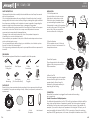
PREPARATION
The hardware equipment listed below is needed to install the speaker.
PACKING LIST
Ensure that you have received all parts according to the component checklist prior
to installation. If any parts are missing or faulty, contact your place of purchase for a
replacement.
Keyhole Saw/
Cutting Saw
Wire Stripper Phillips
Screwdriver
Pencil
Tape
Measuring
Stud Finder
(For Wood Stud Wall)
Safety
Goggles
Ladder
Speaker Grill Cutout
Template
User Manual
INSTALLATION
1.Cut the Speaker Hole
Use a stud finder to locate an area
that is free of obstructions or studs.
Position the cutout template where
you are installing the speaker. Trace
the template to mark out the speaker
location with a pencil. Drill a pilot hole
and cut all of the way around the
circular outline with a cutting saw.
CONNECTION
Ensure that the speaker is unplugged from the mains before making
any connections.
Parallel Connection of Multiple Speakers
For distributed line application, built-in 100V multi-tap transformer offers the ability to
daisy chain multiple number of speakers in parallel. The total number of speakers
multiplied by the tap value cannot exceed the output power of the amplifier. For
example, if you want to daisy chain 5 speakers in total using the 15W taps, you will
need an amplifier with at least 5x15W = 75W. A good rule of thumb is to select an
amplifier with 20% greater power; in this case, an amplifier that delivers about 100W.
2.Wire the Speaker
Pull the speaker wire out of the hole
which you have cut and connect it to
the speaker as shown.
3.Install the Speaker
Place the speaker into the ceiling and
tighten all the clamp screws with a
Philips screwdriver.
4.Attach the Grill
As several magnets are on the speaker
frame, attach the grill to the rim of the
speaker directly. Ensure the grill is
attached to the speaker securely to
keep the grill from falling.

CS5T / CS6T / CS8T
Por favor, lea el manual antes de usar el producto
MANUAL
DE USUARIO
3
CS5T / CS6T / CS8T
Nota: Cada vez que note distorsión, reduzca el volumen a un nivel más bajo. Nunca
permita que su amplificador entre en “recorte”. De lo contrario, los altavoces
podrían dañarse. La garantía no cubre los daños causados por operar los parlantes
a niveles de volumen distorsionados.
CUIDADO Y MANTENIMIENTO
·Apague la alimentación del altavoz cuando no se utilice durante largos períodos
de tiempo.
·Asegúrese de que todo el equipo esté apagado antes de la limpieza. Las
superficies solo necesitan desempolvar/limpiarse ocasionalmente. Nunca utilice
productos químicos o disolventes, ya que pueden dañar la superficie. Limpie siempre
con un paño seco.
·Nunca toque los controladores de los altavoces.
ESPECIFICACIONES
Modelo
CS5T
CS6T
CS8T
Woofer
Cono de fibra de vidrio
tejido de 5,25"
Cono de fibra de vidrio
tejido de 6.5"
Cono de fibra de vidrio
tejido de 8"
Tweeter
Cúpula de titanio de
0,75"
Cúpula de titanio de
0,75"
Cúpula de titanio de 0,75"
Respuesta
frecuente
70Hz-20kHz
60Hz-20kHz
50Hz-20kHz
Sensibilidad
(1M/1W)
90dB 90dB 90dB
Impedancia
nominal
8Ω
8Ω 8Ω
Potencia RMS
40W
60W
80W
Transformador
C100V: 3.75W-7.5W-15W
C100V: 7.5W-15W-30W
C100V: 10W-20W-40W
Dimensiones
Ø204x78mm(Ø8"x3.1")
Ø234x87mm(Ø9.2"x3.4")
Ø284x110mm(Ø11.2"x4.3")
Tamaño del
recorte
Ø179mm(Ø7") Ø210mm(Ø8.3") Ø258mm(Ø10.2")
C
100
15
C
15
C
15
C
15
C
15
C
Amplificador

CS5T / CS6T / CS8T MANUAL
DE USUARIO
1 2
INSTRUCCIONES DE SEGURIDAD
·Lea atentamente las instrucciones antes de la instalación y el uso. Guarde el
manual en un lugar seguro para futuras consultas.
·Antes de instalar los parlantes en cualquier techo/pared, verifique la capacidad de
carga de la estructura y evite el contacto con cualquier cableado o tubería que
pueda estar detrás del área de la superficie. La instalación sobre materiales blandos
o en áreas que no puedan soportar el peso de los altavoces puede causar lesiones
personales o daños al altavoz.
·Asegúrese de que el altavoz esté correctamente asegurado al techo/pared. Utilice
los tornillos, pernos o anclajes adecuados. Si no lo hace, puede que el altavoz se
suelte y cause posibles daños o lesiones.
·Pueden producirse daños en el woofer y el tweeter si el altavoz se cae o se golpea,
lo que da como resultado que no haya sonido o que el sonido esté distorsionado.
·Nunca sobrecargue sus altavoces hasta el punto de distorsión y siempre reduzca el
volumen antes de cambiar las fuentes de entrada.
·Utilice únicamente cableado homologado y certificado en su instalación, no estire
ni ponga el cable en contacto con objetos cortantes.
·Antes de quitar los cables, asegúrese de que toda la alimentación de su
amplificador y otros componentes esté apagada.
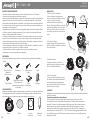
PREPARATION
El equipo de hardware que se indica a continuación es necesario para instalar el
altavoz.
LISTA DE EMPAQUE
Asegúrese de haber recibido todas las piezas de acuerdo con la lista de verificación
de componentes antes de la instalación. Si falta alguna pieza o está defectuosa,
comuníquese con su lugar de compra para obtener un reemplazo.
Sierra de ojo de
cerradura/
sierra de corte
Pelacables Destornillador
Phillips
Lápiz
Cinta métrica
Detector de perfiles
(Para pared con
entramado de madera o
placa yeso)
Gafas
protectoras
Escalera
Altavoz Rejilla Plantilla
recortada
Manual de
Usuario
INSTALACIÓN
1.Corte el orificio del altavoz
Utilice un detector de vigas para
ubicar un área libre de obstrucciones
o vigas. Coloque la plantilla
recortada donde va a instalar el
altavoz. Traza la plantilla para marcar
la ubicación del altavoz con un lápiz.
Perfore un orificio piloto y corte todo
el contorno circular con una sierra de
corte.
CONEXIÓN
Asegúrese de que el altavoz esté desenchufado de la red eléctrica antes de realizar
cualquier conexión.
Conexión en paralelo de varios altavoces
Para la aplicación de línea distribuida, el transformador multi-tap de 100 V
incorporado ofrece la capacidad de conectar en cadena varios altavoces en
paralelo. El número total de altavoces multiplicado por el valor de derivación no
puede exceder la potencia de salida del amplificador. Por ejemplo, si desea
conectar en cadena 5 bocinas en total usando los grifos de 15 W, necesitará un
amplificador con al menos 5x15 W = 75 W. Una buena regla general es seleccionar
un amplificador con un 20 % más de potencia; en este caso, un amplificador que
entrega unos 100W.
2. Conecte el altavoz
Saque el cable del altavoz del orificio
que ha cortado y conéctelo al altavoz
como se muestra.
3.Instala el altavoz
Coloque el altavoz en el techo y
apriete todos los tornillos de sujeción
con un destornillador Philips.
4. Coloca la parrilla.
Como hay varios imanes en el marco
del altavoz, fije la rejilla directamente
al borde del altavoz. Asegúrese de
que la rejilla esté bien sujeta al altavoz
para evitar que se caiga.
-
 1
1
-
 2
2
-
 3
3
-
 4
4


Audibax CS6T El manual del propietario
- Categoría
- Altavoces de coche
- Tipo
- El manual del propietario
en otros idiomas
- English: Audibax CS6T Owner's manual
