Work Pro Digiline Serie Manual de usuario
- Categoría
- Controladores de DJ
- Tipo
- Manual de usuario
Este manual también es adecuado para

User manual
Version 1.2
MX MKII
Manual de Usuario

Detailed Safety Instructions
SAFETY INSTRUCTIONS
CAUTION
RISKOFELECTRICSHOCK
DONOTOPEN
WARNING:
CAUTION:
Read the Instructions:
Main Supply:
Ventilation:
Moisture:
Hot:
Operating:
Service:
To reduce the risk of electric shock, do not remove cover of the device. There is not serviciable
elements inside it. For service purpose, refer to qualified personnel.
To reduce the risk of fire or electric shock, do not expose the unit to rain or moisture.
This sign, when displayed, warms of the presence of a dangerous voltage without isolating inside the unit and that
may be sufficient to constitute a risk of electric shock.
This sign, when displayed, warms of the presence of an important statement for the operation and maintenance
of the unit.
Read all safety and operating instructions before starting the device by
first time. Keep the user manual for future reference beside the unit.
Follow all instructions and warnings inside the user manual and the own
device.
Switch off the unit and disconnect the main supply after using it, specially,
during an electric storm. If liquids have been spilled, metallic objects have
entered inside the unit or the device generates smoke or strange smell
and looks like malfunction, switch it off immediately and contact with your
distributor.
The device must be placed far from hot sources like radiators,
temperature registers, heating conductions or anything heat source.
In order to avoid the risk of electric shock or fire, do not expose the unit to
rain or moisture, using it in dry environments. Also, avoid spill liquids
inside the unit.
To avoid damages in the unit, be carefully during the transport, using its
original package and avoiding to place heavy objects over it. During its
installation avoid to hit or scratch it. Also, avoid to expose the device to
great vibration environments.
Use the main supply cable closed to the unit in a grounded socket
If the socket has not ground terminal, consult with an electrician
to amend it.
The device must be connected to earth by security and optimum
performance. DO NOT remove the ground pin in the socket.
Connect the unit with the voltage and power recommended in this
manual.
Do not cover the air opens in order to achieve a perfect ventilation
of the unit.
PAGE 01

Additional notes about Security and Maintenance
1.1. Introduction
1.2. Specifications
- Contact with your dealer in case of table replacement.
THE UNIT MUST BE EARTHED
- Protect the cable to be pinched or stepped, particularly in connector, socket or where the cable out of the unit.
- Before connecting the supply, check if the local voltage is matched as value marked in the rear side of the unit.
- If the fuse blows, replace it by another fuse with the same dimensions and rate. If it blows again, do not replace it and contact with
your dealer in order to check the unit.
- To disconnect the unit catch from the socket, never pull the cable, it can cause its breakage and produce electric shocks.
For the servicing or maintenance of the unit, contact with your dealer. This process must be done by qualified personnel.
By security reasons and in order to avoid electric shocks, the main supply
cable has a ground terminal. This pin MUST NOT BE REMOVED.
If the connections socket has not the adequate pin, contact with an
electrician in order to change the obsolete socket.
Technical data
Digiline MX
Inputs: 8 double MIC inputs (with phantom) + LINE balanced and one additional MIC input. All of them have Euroblock connector.
Outputs: 8 outputs with Euroblock connector.
Control interface: TCP/IP, RS232 and GPI.
Control connections: RJ45 (Ethernet TCP/IP) , DB9 (RS232) and Euroblock (GPI).
Control software:
Control indicators: Frontal LEDs for signal presence, input & output clip.
WorkCAD designer (Software available to download at www.workpro.es)
Frontal controls: ------------
GPI inputs: 12 GPI (TTL inputs software selectable).
Input sensitivity: 0 dBu (20 dB PAD).
Phantom supply: 15 V MIC inputs (selectable).
THD+N: < 0.1 %.
DSP features
Matrix mixer: 8 mixers of 8 channels with reverse signal and mute for any channel.
Crossover: Butterworth type fi lters, Linkwitz-Riley and Bessel up to 4° order with up to 7 filters per output.
Equalizer: Equalizations with peak type curves, low pass, high pass, notch, low shelving, high shelving and band pass with up to 7 fi lter
per output maximum.
Dynamic control: Common Limiter compressor for f irst 7 channels and an independent one for the last one.
Output channel volume control: Selectable by software and frontal potentiometer (36 dB to -109 dB range). 48 bit processing architecture with 76 bits of
precision for most audio processing features.
Presets memory: 10 program memories available.
DSP Architecture: 32 bit processing with 40 bits of precision.
Oversampling: 8 x Oversampling with fi fth order noise shaping @ 32-48 kHz; 4 x Oversampling @ 88.2 and 96 kHz; 2 x Oversampling @
176.2 kHz and 192 kHz.
Digital De-emphasis: For 32,44.1 and 48 kHz.
Physical Features
Power requirement: 50 W .
Main supply: AC 90-264 V (automatic).
Dimensions (WxHxD): 483 x 44 x 229 mm.
1. DIGILINE DEVICES
Digiline MX MKII by itself is exclusively dedicated to processing uses, it means it doesn´t include amplifier. In only 1 HU 19" rack
unit, it is a very interesting alternative for those who already have a power amplifier or for others who need more power at the
outputs.
The remote control can be operated through ASCII orders by RS 232 or TCP/IP. Thus, it is possible to program automatic actions
like preset changes, mute for all channels except one, etc. It also features 12 GPIO inputs/outputs, providing further configuration
possibilities.
Digiline MX MKII features a RS232 port in order to receive ASCII orders from external devices that use this protocol. It is possible
to program automatic actions like preset changes, mute for all channel except one, etc.
PAGE 02
WorkCAD Designer, Conguration software available to download at www.workpro.es

1.3. Contents
x 17
x 4
x 1
1. INPUT SG/CLIPPING LED: It lits in green colour with audio signal
on corresponding input. In clip state the colour change to orange.
2. OUTPUT CLIPPING: It lits when output clip level is detected in the
corresponding output.
1.4. Front Panel
1.5. Rear Panel
4
5
2
1
1
1
2
2
3
4
5
67
8
9
10
3
3. POWER LED
4. LAN LED: It lits with LAN network presence
5. SWITCH ON/OFF
1. MIC Inputs 1-8: Balanced MIC level inputs.
2. LINE Inputs 1-8: Balanced LINE level inputs.
3. PAD Selection: Select the attenuation level for each
input using this dip-switch block (0 dB or 20 dB)
4. PHANTOM Power: Select the MIC channel to
apply 15V Phantom power.
6. LMI Balanced level Input
7. GPIO Inputs (1-12)
8. RS 232 port: It allows to receive OSC sentences for external device
9. LAN network connection: Connect the unit to a LAN using an UTP CAT5 cable.
10. AC MAINS SOCKET
5. Outputs 1-8: Balanced outputs to c onnect them to an
external amplified system.
PAGE 03
MX MKII

1.7. Device Connection
1.7.1. Audio Signal Connection
MIC 1
LINE 1
Balanced input signal
Balanced input signal
(MIC level)
(LINE level)
DIGILINE sums internally
both signal applied in the
same input.
Digiline devices
network has DHCP, which will provide a valid IP address to the device.
In the same network must be connected a computer with installed WorkCAD control software.
NOTE: If your network has no DHCP connection, the device will usea local-link IP within 169.254.XX range,
being XX a direction supplied by the device upon its connection to not interfere with other devices in the same network.
WorkCAD software will detect the device for configuration.
NOTE: Each DIGILINE include a stick with MAC information and IP static inside 10.XXX.XX.XX You can connect
it to a computer with the same Subnet using a crossover cable between them.
must be connected to an ethernet LAN using a Cat 5 cable with RJ 45. In this case is advisable that the
IMPORTANT
For a complete DIGILINE configuration, the user requires basic
knowledge management networks and/or the connecting server
administrator permissions.
The device integrating is achieved by connecting it to a node in an Ethernet switch, which allows all devices on the
LAN network interconnection.
IP address assignations is automatic thanks to the DIGILINE device control software through MAC address of the
own device.
1.7.2. LAN Connections
DIGILINE MX series devices incorporate an array of 16 external sources of input audio (8x2).
Therefore,each of the 8 inputs allows the connection as much MIC level device as LINE level device.
These 2 input sources are summed internally,forming the processing signal of each input.
Input Connection. The insertion of signal in DIGILINE MX MKII is made through a 3-pin terminal blocks (as much MIC inputs as
LINE inputs), corresponding to a balanced
audio signal (+, GND, -). To do this, a 2 conductors shielded cable should be used
PAGE 04
MX MKII

LAN
ETHERNET
2.1. Installing WorkCAD software
1. Insert CD that comes with the unit
2. A window opens to inform the start of software installation process. Click Next and follow the steps for the installation
process.
NOTE: After the installation, a window informs you that a new extension (* WPJ) is associated to WorkCAD. This
extension is used by projects created.
2. WORKCAD DESIGNER
WorkCAD Designer is the new software of WORK® for device control through Ethernet. Its intuitive interface allows
managing any device parameters configurable.
The exclusive design of WorkCAD Designer provides great benefits for users. Units connected through Ethernet are
visualized in a unique computer: WorkCAD Designer can group devices in projects (each one with different zones) and
name inputs and outputs, taking advantage of a intuitive management and visualization of the overall installation. It is
also possible to select a device and edit its parameters (e.g. IP address, name, preset, filters, etc.).
Programming operations can be done online and offline modes. Changes are instantaneously saved when WorkCAD
Designer is connected. On the contrary user can use the offline mode to prepare and save a show without affecting
current process.
Day after day, engineers of WORK® R&D department design new products and improve existing ones. For this reason,
WorkCAD software makes possible the integration in the same interface of all the devices of the brand, even those
that will come to the market in the future. And because WorkCAD Designer is a free software, anyone can get and
use the latest versions.
Improvements not only concern the software but rather any devices. Indeed, WorkCAD Designer is able to find firmware
updates online and so to upgrade the device firmware. It ensures maximum reliability and compatibility of WORK®
devices with next systems coming out.
DEVICE 1
IP: 192.168.1.2
Subnet: 255.255.0.0
PC
IP:192.168.1.1
Subnet: 255.255.0.0
VIRTUAL DEVICE
PHYSICAL DEVICE
WorkCAD concept is clear with this scheme. The software allows to edit or configure a compatible device
DIRECTLY (connected in the same LAN), or to create a virtual device, configure it and dump the information in a
physical device a posteriori.
PAGE 05
MX MKII

2.2. WorkCAD (Common Interface)
2.2.1. DEVICES
WorkCAD incorporates common sections available for all compatible devices. In the next pages, we go to explain
these common sections:
PROJECT
INSPECTOR
OSC
HISTORY
DEVICES
INTERFACE
WorkCAD works with the virtual and physical device concept. in the first case involves using a device from the
library elements and configure OFFLINE its settings for a later dump to a physical device connected to the network.
2.2.1.1. Library
Within the DEVICES window there are two tabs:
The Library tab includes a drop-down with all devices compatible with WorkCAD software.
The Network tab lets you locate a physical device connected to the network.
You can create presets but, in order to use them, you need to download them into a physical device. Consult
(3.2. PRESETS) section for further information.
Accessing to the Library tab, it displays a menu
with the WorkCAD software compatible devices.
After selecting the device , double click the "+" sign
next to the name to display its control interface on the
right side of the screen.
Furthermore, the device will appear in the Project
Inspector tab to associate it with a group of devices.
NOTE: As we are working OFFLINE, the LED next to
name in Project Inspector window is off.
WorkCAD Designer is the new software of WORK® for device control through Ethernet. Its intuitive interface allows
managing any device parameters configurable (general visualization of the installation).
PAGE 06
MX MKII

2.2.1.2. Network
2.2.1.3. Connecting virtual & physical devices between them
Accessing to the Network tab, the software search devices
compatible with WorkCAD in the network.
After to search a connected device , you can see two symbols en the same device
line:
"+" symbol allows to integrate it in a group inside PROJECT INSPECTOR and,
later, to aaccess to its control interface on the right side of the screen.
Double click over it. A bar will be appears during the process, it means that the
software is retriving the loaded presets in the physical device in to show them in
the interface and work with them, (editing, copying, etc).
Furthermore, the device will appear in the Project Inspector tab to associate it with
a group of devices.
NOTE: As we are working ONLINE, the LED next to name in Project Inspector
window is on in green color.
If you mouse over "i" symbol, will be showed with all device information like Name, Type, MAC address,
IP and Subnet and, finally the firmware version.
NOTE: Check this last line, if it appears "Not Updated" close to the version, the device will need an update
in order to work with it. Consult the (4. Updating firmware) section for further information.
a window
Depending on the installation, in some occasions could be that we need to prepare the presets and device setup
without the physical device presence (the device is in another place, the device is turned off, or we want test any
previous configuration). Therefore, we can load the device form the library and work on this virtual device and
later, dump the information into the physical device. There are two possibilities:
1st Possibility: We are working in a computer in the same LAN where the device will be connected.
In that case, search the device from Network and follow the steps to add it in Project Inspector tab. Now
there 2 devices in Project Inspector: one with green circle (physical device) and another without circle (virtual device).
The next step is to dump the whole information from the virtual to physical device, therefore, select the virtual one
and press Setup in General tab. Now select the icon Copy Device in Connection settings. Press the physical device
in Project inspector and thePaste Device in the same section. The software will transfer the information between
both units.
You still have 2 devices in Project Inspector and you can eliminate the virtual in case yo do not need it or
you can preserve it in order to make test configuration and repeat this process in the future.
2nd Possibility: We are working in a different place where the DIGILINE is connected.
We could set the device from our office and, later go to the installations and dump the configuration. In that case,
after to finish the setting, press File tab in the upper left corner and select Save As in order to save all setting
as project. After, in the installation, load the project generated file (from File tab). the Project will be loaded and
now you can repeat the same process described in the previous point: Load the physical device from Network and
Copy/paste the information.
PAGE 07
MX MKII

2.2.2. PROJECT INSPECTOR
The PROJECT INSPECTOR window allows you to create projects with any WorkCAD compatible device associating
it with a virtual device from the library or working “in situ” with the physical device connected to the network.
The creating project involves ALL devices grouped under the project. Click the File tab to managing projects, creating a
new one, opening an existing or saving a new project.
When you select one device (using Library or Network tabs), the device will be assigned to a group on this menu.
Depending on the color of the circle closed the name, a different state will be present:
Digiline MX in
CONNECTED state
Press Edit to change featuras like:
- Interface language (English/Spanish)
- Enable/Disable the search of updates
- Enable/Disable the hardware acceleration
(This features must be disable if the software
shows problems loading the device)
Two devices in project Inspector: Physical (green circle),
Virtual (no circle)
C. Select virtual Device
and press Copy
Device.
D. Select Physical
Device and press
Paste Device.
A. Create a virtual device and configure it B. Load a device from Network
A. Create a virtual device and configure it. When finish, store all information in a project file (*.wpj) using File Tab. In the installation.
Load the project using the same File tab. Now follow the previous B, C, D points.
1st Possibility
2nd Possibility
PAGE 08
MX MKII

2.2.3. OSC HISTORY
Each modification on any parameter: level variation, creating filter, limiter adjustment, etc., makes an OSC command
that is shown in OSC HISTORY tab. Thus it is posible to copy this command to generate a command list for any interface
that will allow OSC commands to execute such orders.
The sentence showed on this tab is informative, checking easily the action and the created value. The software will
convert this sentence in an OSC compatible command.
Black: The device has been loaded from the library and it has not been associated to a physical device.
Green: The device has been loaded from the network. It is a physical device and it is connected with the software.
Grey: The software has found a device in the network and, later, the device has been turned off
Blue: The presets loaded in the physical device are different as presets created in the software. It is necessary a
sync.
NOTE: When a device is selected from network and the software is loading the presets, this color
appears during the process. When the load finish, the color change to green.
See (2.2.1.3 Connecting virtual & physical devices between them) section for further information
.
In this example we have created an equalization filter with the values ??shown below. automatically appears
the command line in OSC HISTORY tab.
Then you can copy the command line to the clipboard in order to copy it to our external commands control software.
For this we use the icon on the left, but we must first click on the icon right to select the type of format you want to
become the line:
Ethernet or Serial depending on where you connected the control. (Ethernet Port or RS 232 Port respectively)
In the first case, the line is as follows: //out1/eq/1;ifff;4;66.12;-19.48;0.707;
In the second case, the line is as follows: #//out1/eq/1;ifff;4;66.12;-19.48;0.707;\
PAGE 09
MX MKII

3. DIGILINE INTERFACE
Once explained the common functions in all WorkCAD compatible devices. We pass to explain the specific DIGILINE
interface.
Once selected a device (from the Library or the Network) and checked that the device appears in PROJECT
INSPECTOR tab, it is time to open the configuration interface.
1
3
6
2
4
5
1. CONNECTION STATUS: This tab shows the status of the selected device:
2. PRESETS: DIGILINE devices allows to create and manage up to 9 presets to store different configurations. Using
this tab, you can select, Change their names, copy/paste and store them. Also, you can establish a backup point
and access to it (Push/Pop). Finally, you can work in LIVE or EDIT mode.
NOTE: See the (3.2. PRESET) section
for further information
The unit has been selected from
network (We are working over a
physical device).
In that case, the device IP address
is showed in the second line
The device was in the previous state
but it has lost connection. Probably
it is turned off or LAN problem.
The device has been selected from
Library and it has not associated to
any physical device.
PAGE 10
MX MKII

3. CONFIGURATION SETUP: This interface allows to access to the control features on each output. Basically, it
consists in a central graphic window that shows the final result of feature application or change, 8 tabs in the
upper side corresponding to each output and 4 tabs in the left side corresponding to the feature that you can
control on each output (EQ, Mixer, XOver and Limiter).
The slide fader shows the output gain of the selected output.
The icons placed in the right side allows to copy the whole output to another output
NOTE: Check each feature section on the next pages.
4. COMPLETE RESPONSE: Click over the triangle closed "Complete Response". A graphic window will show
the complete curve response of each output with the applied EQ filters, Gain, Xovers, etc.
Push the tick close to the name to show a hide the corresponding output.
The current output is highlighted
5. MASTER CONTROL: This fader controsl the master level of the device. It
appears at all times, allowing to change the whole gain using the fader or changing
the numeric value.
The button over the value allows to change the state: Push it to MUTE the whole outputs
The button over the value allows to change the
state:
Push it to MUTE all outputs. The icon change
to red colour.
PAGE 11
MX MKII

6. GENERAL: This section allows to select the three great blocks of the DIGILINE interface.
By default, the software shows DSP when it is initialized.
- DSP shows the control interface from each output and Complete Response
- GPIs shows the GPI management. DIGILINE devices have a certain number of GPI (General Purpose Input)
that consist in contacts. Therefore, it is posible to assign a command, or a list of commands that will be
executed when the GPI state change.
See (3.3. GPI) section for further information
3
4
- SETUP: You can access to advanced device configuration with the next paragraphs:
Connection Setting: Show all device connection information (IP adresses, Subnet, MAC). The two Copy/Paste
buttons allows to associate a virtual device (loaded from library) with a physical device (loaded from network)
See (2.2.1.3. Connecting virtual & physical devices bewtween them) section for further information
Password Lock: Allows to lock any device section against unwanted manipulations. Simply pick the section,
enter a Password and press Lock button.
Options: Allows to disable the frontal control against unwanted manipulations. The potentiometers values are
then stored and reloaded when the device restarts.
press Apply. It is posible to change Baudrate speed of the serial port of the MX device. It can also be disabled.
PAGE 12
MX MKII

3.1. DSP
Each output has its own configuration window in order to modify the following parameters
EQ, MIXER, CROSSOVER, LIMITER
Selecting the adequate Output in the upper tabs you can configurate these parameters on the output and, using
the icons placed in the right side, copy the whole configuration from one output to another output.
The fader marked as Level, allows to control the gain of the selected output, moving the fader or changing the numeric
value. The buttons over the numeric value allows to select the state. MUTE allows to cut off the output (it change to
red colour) and INVERT will invert the output phase (it change to yellow colour).
You can navigate through the output parameters selecting the left side icons (EQ, Mixer, XOver and Limiter).
3.1.1. EQ
DIGILINE devices allows to create up to 7 equalizer filters, editing their features easily.
Band: This dropdown menu allows to select the filter (between 1 to 7) in order to edit its features.
Type: This dopdown menu allows to select the filter type between Bypass, Peak, Low Pass, High Pass, Low
Shelving, High Shelving, Band Pass, Notch and All Pass.
Frequency: Changes the central frequency point of the filter (in Hz). Type the chosen value.
Gain: Changes the filter gain (in dB). Type the chosen value.
Qfactor: Changes the Qfactor of the filter. Type the chosen value.
The graphic window will show the curve response after apply the changes. Each filter has two points. The green point
marks the Frequency and Gain, therefore, it is possible to move this point using the mouse and the numeric values will
change, and viceversa, changing the numeric values, the point will be move to the corresponding graphic position.
The red point has the same behaviour but using the Qfactor value.
The Copy/Paste icon allow to copy the EQ tab between outputs
On this example, we have created a Low Shelving
filter at 40 Hz, with a Gain of -15 dB and 0.8 as
Q factor. The response curve appears in the graphic
windows. In that case, the most lower green and red
points correspond to this filter.
Also, in OSC HISTORY has been created an OSC
command corresponding to this filter creation.
PAGE 13
MX MKII

3.1.2. MIXER
This tab allows to configure which inputs (from the 8 inputs included in the DIGILINE) and which value and state will be
present in the selected output. Therefore, we can create a 8 input/8 output matrix setting their levels.
3.1.3. XOVER
This tab allows to create two crossover filters: High Pass Cut and Low Pass Cut.
For both filters we can configure the frequency (fc), the type of filter to select between three types (Butterworth,
Linkwitz-Riley or Bessel) (Type), and the magnitude order of that filter (Up to 8 orders) (N).
The obtained response curve applying both filters is displayed on the screen. The horizontal axis shows the
frequency in Hz and vertical the gain in dB.
As much as Master fader or Level fader, the gain level can be set moving the fader or typing the value in the cell.
Also, it is posible to change the state of each input (MUTE (in red colour), INVERT (yellow color) or active (both
icon not highlighted)
Like each DSP section, a command sentence will appears in OSC HISTORY each time that we change any value.
In that case, the last action has been to change de Gain value of the Input 5 applied to Output 1 and changing the
state to MUTE.
PAGE 14
MX MKII

In this example, we have configured a 5th order Butterworth High Pass filter at 70 Hz and a 4th order Linkwith-Riley
Low Pass filter at 16 kHz.
The curve response is showed in the graphic window.
Using the Copy/Paste icon, it is possible to copy this filter to another output
Like each DSP section, a command sentence will appear in OSC HISTORY each time that we change any value.
In that case, the last action has been to create the Low Pass filter to Output 1 with the example values.
At this moment, the Complete Response and if it is shown only Output 1, you can see the complete response
after applying the Xover and EQ filter explained in this example.
PAGE 15
MX MKII

3.1.4. LIMITER
In this tab you can enable and adjust the different sections of the limiter by clicking on its respective
the window.
In the graph you can see the curve obtained after the application of each element (highlighted line). The dashed line
will show the bypass condition (in order to compare both cruves).
.
Limiter
It set with the top point of the graph with the Threshold knob. When enable, it pass to gray color and can be moved
and set its level.
Compressor
Compression is set to the next point, also changing to gray to allow movement. with the Compression knob you can
adjust the ratio.
Noise Gate
A noise gate is set to the lowest point, the ratio can be adjusted with the related knob.
Take into account that outputs 1 to 7 has the same Limiter and the Output 8 has its own Limiter
configuration.
NOTE: Each Limiter
section can be enabled
or not. Simply push
the chosen selection.
Use the Copy/Paste
icon to copy the
Limiter setting. In that
case from Limiter 1-7
to Limiter 8 or viceversa.
NOTE: The highlighted
line represent the response
curve after apply the
Limiter elements. The
other curve show the
response in Bypass state.
tab inside
Like each DSP section, a command sentence will appears in OSC HISTORY each time that we change any value.
IMPORTANT
PAGE 16
MX MKII

3.2. PRESETS
DIGILINE devices incoporates 9 Presets in order to save different configurations, allowing to load one of them
directly on the device or to edit its properties.
The PRESET tabs has the next functions:
LIVE MODE/EDIT MODE: The device starts by default in LIVE MODE. On this condition, the changes will be
applied inmediately. If you press this button, the device pass to EDIT MODE. On this condition, the device will
modify its presets, but NOT the executing process. Later, the new preset can be executed.
PUSH/POP: These buttons allow to create a backup point of the executing audio path. Therefore, if you start from
a specific configuration and want to set temporaly another parameters, you can press the PUSH button, so the
current execution is stored and , then, make all the needed changes. After that, when the user wants to go back to
the initial state, then just push the POP button to restore the previous state.
NOTE: This function only works in LIVE mode.
PRESET Selection: This drop-down menu allows to select one of the 9 presets included in DIGILINE.
CHANGE NAME: The preset can be renamed selecting the preset and pressing this button.
STORE PRESET: It allows to save the whole configuration in the selected preset.
EXECUTE: It allows to execute a preset previously stored. In EDIT mode, select a preset and press EXECUTE,
WorkCAD retrieves the preset, activate LIVE mode and execute the selected preset.
NOTE: This preset will act immediately due to the unit is in LIVE mode, therefore, we can made any change
but it only will be effect “in situ”, the preset will no change unless you press STORE PRESET and save
the new changes over the previous preset.
NOTE: EXECUTE function only works on EDIT mode
COPY/PASTE: These buttons allows to made a preset copy and paste in another preset.
NOTE: After to paste the preset, press STORE PRESET in order to finish this process.
A situation can occur is that you are not connected with the physical unit and you have stored any presets. Under
this condition, the presets ONLY exist in the software. If you try to connect to physical device. The software will
alert that both devices (virtual device present in the software and physical device have not the same stored presets,
they are desynchronized.
PAGE 17
MX MKII

You can see that the unit in the PROJECT INSPECTOR has a blue colour circle close to the name, it means that
both units are desynchronized.
Press on "ReSynch" button. It will appears to options: Device and Local, asking you which device is the correct one,
Device for physical device or Local for information present in the software.
Choose the desired option, the sotware will synchonize both device, loading the preset from our choice.
After this action, the point together the device in PROJECT INSPECTOR will change to green colour.
NOTE: This circumstance also occurs in the case of load a device from the library and setting it, creating
and saving presets. After, when you want to connect and load this information on a physical DIGILINE, both
devices will be different, therefore they need to be synchronized. In that case, the correct choice will be
Local.
3.3. GPI
DIGILINE devices incorporate GPIs (General Purpose Input), 12 GPI for DIGILINE MX.
Also, both devices incorporate LMI input. These inputs are contacts. We can assign to them commands to be executed
in both states: When the GPI is activated or deactivated.The LMI is a microphone analog input that, from the selected
threshold, allows to execute the assigned commands. LMI is very adequate as talkover.
GPI interface is accessible through GENERAL tab.
Hysteresis cycle
When the input is greater than High
Level, the state pass to ON ACTIVATE.
When the input is less than Low
Level, the state pass to ON DEACTIVATE.
The Low and High level
must be set bettween 0 to
4000, When "0" means 0V
and "4000" means 3V.
LMI setup
PAGE 18
MX MKII

This interface lists the GPI (1 to 12) and the LMI. A blue circle next to the number of GPI displayed the selected GPI to
be programmed.
1
2
2
1
3
3
3
3
4
5
2
4
5
6
6
6
The OSC Method window displays the various commands generated with their values which will executeby acting
on the previously selected GPI and in the state selected in the Events tab.
The icons of section allow, given a series of commands, change the order in which they will run,
passing, for example, the third command to the first. This uses the icons for scrolling.
The icons on section allow to:
The icons allow to copy all the commands contained in another GPI to another GPI (Copy / Paste).
The icon will save the entire list of commands in the GPI and state previously selected.
After creating a command in section , pressing this icon, the command will appear in the OSC
Method window
After creating a command in section , pressing this icon, and having selected a command
in OSC Method window, this new command will replace the selected.
You can select a command in the OSC Method and delete it using this icon.
The Events tab lets you select what state they must find the GPI to execute commands.In On Activate position, the
software will send commands when the GPI is actived (that is, when the contacts are closed). In contrast, selecting the
On Deactivate mode, the command is executed when the contacts are released.
PAGE 19
MX MKII

Method Editor tab allows the creation of commands with a simple and intuitive edition of its values and
states.
WorkCAD recognize the device and Commands List window displays a popup menu with commands
susceptible editing along with a brief description of their duties.
Each selected command has a set of values to edit, depending on the purpose of that command.
In this example we have selected the Output Gain command to edit the output value and their status.
- On the first line enter the value of the output channel to modify.
- In the second line the dB value you want for the selected output
- The third line allows you to select the Mute status. In this case the options are T (true) if you want the output
is in Mute, or F (false) if we do not want to mute the output.
- The fourth line to select the state Invert. In this case the selection is performed in the same manner as in
Mute previous value.
In this example we have edied this command with the following values: At output 1 we have given a value of
4 dB, leaving the output without applying a Mute or invert its phase
Once written the values, click the icon and the command will appear in the OSC Methods
If you press the icon will delete the selected command line.
6
3.3.1. Commands
PAGE 20
MX MKII

From here the process is identical, in the list of commands (Commands List) select the wished command
to edit.
The values introduction allows certain rules:
a. Parameter Range type that incorporate the following text:
Range (number, [first-last], [firs-last,another])
In this case the value can be numerical referred to a single channel:
1 for channel 1.
We can set a range of channels in brackets ([ ]) and separated with a hyphen (-):
[1-4], in this case we have selected the first 4 channels.
We may also collect both previous methods separating with commas (,):
[1-4], 6. In this case we have selected the channels 1-4 and 6.
We can also select alternate channels:
[1,3,6] allows us to select channels 1, 3 and 6 only.
As a last resort selection, we can make the following value:
*. In this way you select ALL CHANNELS.
The use of these symbols allows us to reduce the number of commands.
b. Float type parameters that include the following text:
Float (float number) and in description (1 or 0)
Here are parameters of two states: 0 if not want to activate this parameter or 1 to activate
c. Float type parameters that include the following text:
Float (float number) and in description (in dBs)
In this case these parameters allow edit the value in dBs.
d.
Float (float number) and in description (negative for decrecement)
If the value is negative (placing a dash (-) before the
value), this value reduces the value previously established in the amount of dBs marked, and a positive value
(no hyphen in front) increases it.
Float type parameters that include the following text:
In this case these parameters allow edit the value in dBs.
In this example we used the command Output Gain: Mute with Fade, you can select an output and
take it out of the state or a certain level Mute fade.
We applied that command on channels 1 to 4 and 6 [1-4,6] and activated the Mute status (1) in
the second line parameters.
In this example we used the command Output Gain: Increment, which lets you select an output and
increase or decrease the gain value using the second line.
We applied that command on channel 2 by typing 2 in the first parameter and writing -5 in the second, of
This way, we will reduce the value 5dB previously had output number 2.
PAGE 21
MX MKII

d. Boolean parameters that include the following:
Boolean (T, F)
In this case input parameters for a true value (T = TRUE) or False (F = FALSE), referred to the parameter
application or not.
In this example we used the command Output Gain: you can select an output, giving a gain value and modify their
state MUTE and INVERT.
We applied that command on channels 3-5 writing [3-5] in the first parameter, giving 10 dB Gain of these channels (10).
and leaving channels without mute and phase reverse writing F as False.
3.3.2. Other Commands
The commands previously shown refer to actions performed with the outputs. They all appear in the dropdown menu
as Output Gain: .....
1. Mixer: .....
In this series of commands, you can assign a certain number of inputs to a particular output and modify its gain and
MUTE or INVERT .
IMPORTANT: refer to INPUT CHANNELS
status
MUTE and INVERT
In this example we have assigned to output 3, inputs 2 and 4 with a value of 4 dB. These two inputs are
are inverted but not muted.
2. Equalizer Output, CrossOver, Limiter/Compressor
These three commands allow you to create EQ and crossover filters and adjust the limiter / compressor.
IMPORTANT: These commands are more sensitive to create, especially the limiter / compressor so
need some knowledge of the values ??that are being edited and the impact they can create the modified
output.
PAGE 22
MX MKII

Equalizer Output
In this example we have created an equalization filter at Output 3 (Output Channel = 3)
We employed the 1st band (Band Index = 1), so we started on the left side of
response curve (See 3.1.1 EQ on page 17 for additional information).
We selected Low Shelving filter type (Type = 4). This number is determined by the order
occupies within the filter type drop-down. CONSIDERING THAT THE FIRST FILTER (BYPASS)
HAS VALUE 0.
Bypass = 0, Peak = 1, Low Pass = 2, HighPass = 3, Low Shelving = 4
High Shelving = 5, Band Pass = 6, Notch = 7, All Pass = 8
Parameters Frequency (in Hz), Gain (in dB) and Q, allow to adjust the values of the filter created
CrossOver
In this case we have created two crossover filters at Output 3 (Output Channel = 3)
We have created a Butterworth type high-pass filter ( high pass type = 0) and another Linkwith-Riley as
low pass filter (Low pass type = 3). The nomenclature of these filters is due to the following table:
Butterworth 0 Butterworth 1
Linkwith-Riley 2 Linkwith-Riley 3
Bessel 4 Bessel 5
NOT USED 6 NOT USED 7
TYPE VALUE TYPE VALUE
ByPass 8 ByPass 8
HIGH PASS TYPE LOW PASS TYPE
High / Low pass order p are the order of the filter. (In this case 3rd and 2nd respectively)
High / Low pass frequency values are the frequency in the filter in Hz (150 Hz and 12,000 Hz in this
case).
(See 3.1.3 XOVER on page 18 for additional information).
arameters
PAGE 23
MX MKII

Limiter/Compressor
Since this command can set the filter and compressor in the required channel.
Again, remember to be aware of the values that are entered in the various parameters.
These values can affect not only the performance of the facility, but to the connected devices.
IMPORTANT
3. Presets: ....
4. Channels: ....
5. UDP Port:
With these commands you can set the preset parameters, either to rename, save,execute or set a backup point.
(See Section 3.2. PRESETS for additional information)
The commands are:
- SetName: To rename the selected preset.
- Set Editing State: Change Live mode / Edit on the device.
- Execute: Executes the selected preset
- Live Copy to Preset: Copy the preset in Live mode to a selected preset
- Live Push: Stores the preset as a backup to restore it after
- Live Pop: Restores the previously saved preset with Push, discarding any changes made meanwhile.
IMPORTANT: In the list of commands in this section shows a number of them starting with Preset: Get ....
and that they have associated parameters. In this case the scope of use is more focused to Ethernet
controlled by commands being sent back by the UDP port the requested information.
With these commands you can rename both the inputs and outputs:
- Set Input Name: Change the name of the selected input
- Set Output Name: Change the name of the selected output
IMPORTANT: As in the previous section, the commands which incorporate "GET" behave similarly
This command changes the UDP port value. Originally the value of this port is 9000
PAGE 24
MX MKII

2. Push the "i" symbol closed the device name to show its information (MAC, IP address, and firmware version).
Check the last line which shows the firmware version and , closed to it the word “(Not Updated)”. On this
conditions, it is necessary to update the device firmware.
4. Updating Firmware
Depending on the Digiline devices firmware, could be necessary to update it.
PROCESS
The first step is to check the firmware version of the device:
1. Select the Network tab, the software will show the devices found in the LAN (in this example, Digiline MX)
3. Push the symbol "^" in the same line to start the updating process. A confirmation, will
appears. This symbol only appears when the device is not updated
windows requesting
The device
needs to be
updated
PAGE 25
MX MKII

4. The updating process starts. It will take some minutes. When it finish, a windows will be showed indicating
the device is updating successfully.
5. If you push the "i" symbol again, check the last line with the installed version and the word "updated"
together.
Also, the symbol
“^” in the device line
6. Now the Digiline device is updated and ready to use the new WorkCAD software.
has dissapeared.
IMPORTANT
If you have used and setup a Digiline with a previous software version, take into account these points before
updating the device:
A. The GPIs previously stored in the DIGILINE device WILL BE DELETED AFTER UPDATING PROCESS and
must be to created again.
B. Check your current firmware version, if this version is 9.13.14.0.0 or later, the presets previously
stored in the DIGILINE ARE FULLY COMPATIBLE WITH THIS VERSION, Therefore, these presets DO NOT
BE DELETED AFTER UPDATING PROCESS
The device has
being updated
PAGE 26
MX MKII

5. OSC - ASCII converter
We have developed this application to convert OSC commands of WORK® devices into ASCII strings,
in order to program devices compatibles.
This application shows WORK
® devices able to interpret and display the parameters to
each command. You can edit its value and generate the ASCII string.
OSC commands associated
1. Press Edit tab and select OSC To ASCII Utility
2. Select the device from the Device List drop-down menu. It Includes all compatible devices WorkCAD
3. Depending on the selected device, has been associated commands to generate the ASCII string. Each command
has its own set of parameters to edit. You can see then in the main window, its description, value and type of
input variable (string, float or boolean).
Also Detected Devices tab will display the compatible devices connected to the same network with the IP address.
In that case, a Digiline MX has been detected in
the same network
PAGE 27
MX MKII

3. Once the parameter has been edited, the application generates the ASCII string in the upper window.
4. This line is generated in two formats at once, depending on what you go for. either by
Ethernet port or by RS232 serial port. (See Section 2.2.3. OSC HISTORY for additional information).
5. Press Copy Ethernet or Copy , according to the control mode to use, and the command line will be
copied to the clipboard for later use.
NOTE: Click the Help icon in the lower left corner for additional information on this application.
NOTE: For an explanation of the commands that incorporate Digiline series devices, see section 3.3. GPI
for additional information.
Serial
In this example we have selected
command : Gain Value and
established a value of 3 dB in the
output 1
Output
PAGE 28
MX MKII

Instrucciones detalladas de seguridad
INSTRUCCIONES DE SEGURIDAD
CAUTION
RISK OF ELECTRIC SHOCK
DO NOT OPEN
AVISO:
PRECAUCION:
Lea las instrucciones:
Alimentación:
Ventilación:
Humedad:
Calor:
Manejo:
Mantenimiento:
Para reducir el riesgo de descarga eléctrica, no retire la cubierta del dispositivo. No hay elementos deç
control para el usuario en el interior. Para su reparación, consulte a personal cualificado.
Para reducir el riesgo de fuego o descargas eléctricas, no exponga la unidad a la lluvia o humedad..
Este signo, cuando se muestra, nos avisa de la presencia de un voltaje peligroso sin aislar dentro de la unidad y
que puede ser suficiente para constituir un riesgo de descarga eléctrica.
Este signo, cuando se muestra, indica la presencia de una importante aclaración para la operación y mantenimiento
de la unidad.
Lea todas las instrucciones de seguridad y operación antes de iniciar el dispositivo
por primera vez. Mantenga el manual del usuario para futuras consultas junto a la
unidad.
Siga todas las instrucciones y advertencias dentro del manual de usuario y el propio
dispositivo.
Apague la unidad y desconecte el suministro principal después de su uso, en especial,
durante una tormenta eléctrica. Si se han derramado líquidos, o entrado objetos
metálicos en el interior de la unidad o el dispositivo genera humos u olores extraños
y, en general, aprecia un mal funcionamiento, apáguelo de inmediato y póngase en
contacto con su distribuidor.
El dispositivo debe colocarse lejos de fuentes de calor como radiadores,
registros de temperatura, conducciones de calefacción o cualquier fuente de calor.
Con el fin de evitar el riesgo de descargas eléctricas o incendios, no exponga la unidad
a la lluvia o la humedad, utilizar en ambientes secos. También, evite derrame líquidos
dentro de la unidad.
Para evitar daños en la unidad, sea cuidadoso durante el transporte, use su embalaje
original y evite colocar objetos pesados ??sobre él. Durante su instalación evite golpear o
rayar la unidad. Además, evite exponer el aparato a entornos de grandes vibraciones.
Utilice el cable de alimentación que acompaña a la unidad en una toma de corriente con
conexión a tierra.
Si la toma no tiene terminal de tierra, consulte a un electricista para modificarla.
El dispositivo debe estar conectado a tierra por seguridad y óptimo rendimiento.
NO retire el conector de tierra en el enchufe.
Conecte la unidad a juna toma con el voltaje y la potencia recomendada en este
manual.
No cubra las salidas de aire de la unidad para conseguir una perfecta ventilación de
la unidad.
Página 29

Notas adicionales sobre Seguridad y Manternimiento
1.1. Introducción
1.2. Especificaciones
- Contacte con su distribuidor in caso de necesitar sustituir el cable.
LA UNIDAD DEBE SER CONECTADA A TIERRA
- Proteja el cable de ser pinzado o pisado, especialmente en el conector, enchufe o en la zona donde el cable salga de la unidad.
- Antes de conectar la alimentación, compruebe si el valor de la toma de red is igual al valor marcadeo en parte trasera de la unidad.
- Si se funde el fusible, sustitúyalo por otro de las mismas dimensiones y valor. Si se vuelve a fundir, no lo cambie y contacte con su
distribuidor para comprobar la unidad.
- Desconecte la unidad extrayendo el conector, nunca estire del cable, podría causar su rotura y ocasionar descargas eléctricas.
Para el mantenimiento de la unidad contacte con su distribuidor. Este proceso debe ser llevado por personal cualificado.
Por razones de seguridad y con el fin de evitar descargas eléctricas, el cable
tiene un terminal de tierra. Este pin NO DEBE RETIRARSE.
Si la toma de alimentación no tiene el pin adecuado, póngase en contacto
con un electricista para cambiar la toma obsoleta.
Datos Técnicos
Digiline MX
Entradas:
8 entradas doble MIC (con phantom) + LINE balanceadas y una entrada MIC adicional. Todas conconector Euroblock.
Salidas:
8 salidas con conector Euroblock.
Interfaz de Control:
TCP/IP, RS232 y GPI.
Conexiones de control:
RJ45 (Ethernet TCP/IP) , DB9 (RS232) y Euroblock (GPI).
Software de control:
Indicadores:
LED frontal para presencia de señal., entrada y clip de salida.
Controles frontales:
------------
Entradas GPI:
controladas por software.4 GPI (entradas TTL normalmente abiertas) para control directo y
Sensibilidad de entrada:
0 dBu (20 dB PAD).
Aliment. Phantom:
15 V entrada MIC (seleccionable)
THD+N: < 0.1 %.
Características DSP
Mezclador matricial:
8 mexcladores de 8 canales con inversión de señal y mute en cada canal..
Crossover: Filtros tipo Butterworth Linkwitz-Riley and Bessel hasta 4° orden con hasta 7 filtros por salida
Ecualizador:
Ecualización con curvas tipo peak, low pass, high pass, notch, low shelving, high shelving y band pass con hasta 7 filtros
por salida máximo.
Control de Dinámica:
Limitador/Compresor común para las promeras 7 salidas y 1 independiente para la octava salida
Control de volumen de salida: Seleccionable por software y potenciómetro frontal (rango de 36 dB a -109 dB). Procesamiento de 48 bit con 76 bits de
precisión para la mayoría de aplicaciones de audio..
Memorias Preset: 10 memorias de programa disponibles.
Arquitectura DSP: 32 bit de procesado con 40 bits of precisión.
Oversampling: 8 x Oversampling con noise shaping de 5º orden @ 32-48 kHz; 4 x Oversampling @ 88.2 y 96 kHz; 2 x Oversampling @
176.2 kHz y 192 kHz.
De-emphasis Digital: Para 32,44.1 y 48 kHz.
Características Físicas
Consumo:
50 W.
Alimentación:
AC 90-264 V (automático)
Dimensiones (AnxALxPr):
483 x 44 x 229 mm.
DIGILINE serie se compone de dos mezcladores digitales con procesamiento de señales, especialmente diseñado para instalaciones
pequeñas / medianas que requieren una potente solución de procesamiento de audio. Su uso intuitivo hace muy conveniente para
instalaciones donde se precise un montaje rápido.
Series DIGILINE permite la mezcla digital para instalaciones multizona pequeñas y la integración de procesamiento DSP
independiente para cada salida. Gracias al software WorkCAD de diseño, es posible controlar cualquier dispositivo DIGILINE
incluido en una red Ethernetdesde un equipo único.
Su interfaz GPI (Entrada de Propósito General) permite activar cualquier función (configurado a través del software) desde un simple
panel mural. DIGILINE MX incorpora 12 GPI. Asimismo, incluyen una entrada LMI parafunciones de talkover
1. DISPOSITIVOS DIGILINE
WorkCAD designer (Software disponible para descargar en www.workpro.es)
Página 30
WorkCAD Designer, software de conguración, descargable en www.workpro.es

1.3. Contenido
x 17
x 4
x 1
1. LED INPUT SG/CLIPPING: Se ilumina en color verde con señal de
audio en la entrada correspondiente. En modo clip el LED pasa a
color naranja
2. OUTPUT CLIPPING: Se ilumina cuando el nivel clip de la salida es
detectado en la salida correspondiente.
1.4. Panel Frontal
3. POWER LED
4. LAN LED: Se ilumina cuando la unidad detecta la presencia de
la red LAN
5. INTERRUPTOR ON/OFF
Digiline MX
1.5. Panel Trasero
1
1
2
2
3
4
5
67
8
9
10
1. Entradas MIC 1-8: Entradas de nivel MIC balanceadas.
2. Entradas LINE 1-8: Entradas de nivel LINE balanceadas.
3. PAD Selección: Seleccione el nivel de atenuación de
cada entrada usando este dip-switch (0 dB o 20 dB)
4. PHANTOM Power: Seleccione el canal MIC para
aplicar alimentación phantom de 15V
6. Entrada de nivel Balanceado LMI
7. Entradas GPI (1-12)
8. Puerto RS 232: Permiter recibir comando OSC desde un dispositivo externo
9. Conexión de red LAN: Conecte la unidad a una red LAN usando un cable UTP
CAT5
10. TOMA DE ALIMENTACION AC
5. Salidas 1-8: Salidas balanceadas para conectarlas a un
sistema de amplicación externo.
MX MKII
4
5
2
1
3
Página 31

1.7. Conexión del dispositivo
1.7.1. Conexiones de señal de audio
MIC 1
LINE 1
Señal de entrada balanceada
Balanced input signal
(Nivel MIC)
(LINE level)
DIGILINE suma internamente
ambas señales aplicadas en
la misma entrada.
Los dispositivos Digiline deben estar conectados a red LAN Ethernet mediante un cable Cat 5 con conectores RJ 45.
En este caso es aconsejable que la red tiene DHCP, que proporcionará una dirección IP válida para el dispositivo.
En la misma red debe estar conectado un ordenador con el software de control WorkCAD instalado.
La integración del dispositivo se logra mediante la conexión a un nodo en un switch Ethernet, que permite la
interconexión de todos los dispositivos en la red LAN.
La asignación de direcciones IP es automático gracias al software de control del dispositivo DIGILINE través de la
dirección MAC del propio dispositivo.
NOTA: Si su red no tiene conexión DHCP, el dispositivo usará una IP de enlace local dentro del rango 169.254.xx,
siendo XX una dirección suministrada por el dispositivo de su conexión para no interferir con otros dispositivos en la
misma red.
El software WorkCAD detectará el dispositivo para la configuración.
NOTA: Cada DIGILINE incluye una pegatina con la información MAC e IP estática dentro 10.XXX.XX.XX Puede
conectara un ordenador con la misma subred mediante un cable cruzado entre ellos.
IMPORTANTE
Para una configuración completa de DIGILINE, el usuario precisa
un conocimeinto básico de gestíon de redes y permisisos de
administración del servidor conectado.
1.7.2. Conexiones LAN
MX MKII
Los dispositivos de la serie Digiline MX incorporan un conjunto de 16 fuentes de entrada de audio (8x2). Por lo
tanto, cada una de las 8 entradas permite la
conexión tanto de dispositivos de nivel MICcomo LINE. Estas 2 fuentes de entrada 2 se suman internamente,
formando la señal de procesamiento de cada entrada.
Conexión de entrada. La inserción de la señal en DIGILINE se hace a través de un bloque de terminales de 3
pines (tanto entradas MIC como LINE), lo que
corresponde a una señal de audio balanceado (+, GND, -). Para ello, debe usarse un cable de 2 conductores
Página 32

LAN
ETHERNET
2.1. Instalando el software WorkCAD
1. Inserte el CD que acompaña la unidad
2. Se abrirá una ventana para informar del inicio de proceso de instalación del software. Haga clic en Siguiente y siga
los pasos para el proceso de instalación.
NOTA: Después de la instalación, una ventana le informa que una nueva extensión (* WPJ) se asocia a WorkCAD.
esta extensión es utilizada por los proyectos creados.
2. WORKCAD DESIGNER
WorkCAD Designer es el nuevo software de WORK ® para el control del dispositivo a través de Ethernet. Su interfaz
intuitiva permite la gestión de cualquier parámetro configurable del dispositivo (visualización general de la instalación).
El diseño exclusivo deWorkCAD designer proporciona grandes beneficios para los usuarios. Las unidades conectadas a
través de Ethernet se visualizan en un equipo único: WorkCAD designer puede agrupar los dispositivos en los proyectos
(cada uno con diferentes zonas) y nombrar entradas y salidas, aprovechando una gestión intuitiva y visualización de
toda la instalación.También es posible seleccionar un dispositivo y editar sus parámetros (por ejemplo, dirección IP,
nombre, preset, filtros, etc.)
Operaciones de programación se pueden hacer online y offline. Los cambios se guardan instantaneamente cuando
WorkCAD Designer se conecta. Por el contrario, el usuario puede utilizar el modo offline para preparar y guardar un
programa sin afectar proceso actual.
Día tras día, los ingenieros del departamente I + D de WORK® diseñannuevos productos de trabajo y mejorar en
los dispositivos existentes. Por esta razón,el software WorkCAD hace posible la integración en la misma interfaz de
odos los dispositivos de la marca, incluso aquellos que llegarán al mercado en el futuro. Y porque WorkCAD Designer
es un software libre, cualquiera puede obtener y utilizar las últimas versiones.
Las mejoras no sólo se refieren al software, sino a todos los dispositivos. En efecto, WorkCAD Designer es capaz de
encontrar el firmware para actualizaciones en línea y así actualizar el firmware del dispositivo. Esto garantiza la máxima
fiabilidad y compatibilidad de los dispositivos WORK ® con sistemas futuros.
DEVICE 1
IP: 192.168.1.2
Subnet: 255.255.0.0
PC
IP:192.168.1.1
Subnet: 255.255.0.0
DISPOSITIVO
VIRTUAL
DISPOSITIVO
FISICO
El concepto WorkCAD está claro con este esquema. El software permite editar o configurar un dispositivo compatible
DIRECTAMENTE (conectado en la misma LAN), o crear un dispositivo virtual, configurar y volcar la información en un
dispositivo físico a posteriori.
MX MKII
Página 33

2.2. WorkCAD (Interfaz común)
2.2.1. DEVICES
WorkCAD incorpora secciones comunes disponibles para todos los dispositivos compatibles. En las siguientes
páginas, vamos a explicar estas secciones comunes.
PROJECT
INSPECTOR
OSC
HISTORY
DEVICES
INTERFACE
WorkCAD trabaja con el concepto de dispositivo virtual y físico. en el primer caso implica el uso de un dispositivo de la
biblioteca y configurar OFFLINE sus ajustes para una descarga posterior a un dispositivo físico conectado a la red.
2.2.1.1. Library
Dentro de la ventana DEVICES hay dos pestañas:
La pestaña Library incluye un desplegable con todos los dispositivos compatibles con el software WorkCAD.
La pestaña Network le permite localizar un dispositivo físico conectado a la red.
Puede crear presets, pero, para utilizarlos, es necesario descargarlos en un dispositivo físico. Consultar
(3.2. PRESETS) para obtener más información.
Accediendo a Library, se muestra un menú con los
dispositivos compatibles de software WorkCAD.
Después de seleccionar el dispositivo, haga doble clic
en el signo "+" junto al nombre para mostrarlo en el
apartado Project Inspector. Al pulsar sobre él, aparecerá
su interfaz de control en el lado derecho de la pantalla.
NOTA: Al trabajar en modo OFFLINE, el LED junto al
nombre en la ventana Project Inspector está apagado
(color negro).
WorkCAD Designer es el nuevo software de WORK® para control de dispositivo a través de Ethernet. Su intuitivo
interfaz permite manejasr cualquier parámetro configurable del dispositivo.
MX MKII
Página 34

2.2.1.2. Network
2.2.1.3. Conectando un dispositivo virtual y otro físico entre ellos
Accediendo a la pestaña Network, el software buscará en la red los dispositivos
compatibles con WorkCAD.
Después de encontrar un dispositivo conectado, se pueden ver dos símbolos en la
misma línea del dispositivo:
El símbolo "+" permite integrar en un grupo dentro PROJECT INSPECTOR y,
más tarde, acceder a su interfaz de control en el lado derecho de la pantalla.
Haga doble clic sobre él. Una barra se aparece durante el proceso, que significa que el
software está recuperando los presets cargados en el dispositivo físico para mostrarlos
en la interfaz y el trabajar con ellos, (edición, copia, etc.)
NOTA: Como estamos trabajando ONLINE, el LED junto al nombre en la ventana
Project Inspector, está en color verde.
Si pasa el ratón sobre el símbolo "i", una ventana se mostrará con toda la información del dispositivo como el nombre,
tipo, dirección MAC,IP y subred y, por último, la versión del firmware.
NOTA: Compruebe esta última línea, si aparece "Not Updated" junto a la versión, el dispositivo necesita una
actualización. Consulte (4. Actualización de firmware) para obtener más información.
Dependiendo de la instalación, en algunas ocasiones podría ser que tengamos que preparar los presets y configuración
del dispositivo sin la presencia de dispositivo físico (el dispositivo se encuentra en otro lugar, el dispositivo está apagado,
o queremos probar cualquier configuración anterior). Por lo tanto, podemos cargar el dispositivo desde la librería y
trabajar de manera virtual,volcando la información en el dispositivo físico. Hay dos posibilidades:
Primera posibilidad: Trabajando en un ordenador en la misma red local en la que se conecta el dispositivo.
En ese caso, busque el dispositivo de red y siga los pasos para agregarlo en la pestaña Project Inspector. Ahora
Hay 2 equipos en Project Inspector: uno con el círculo verde (dispositivo físico) y otro sin círculo (dispositivo virtual).
El siguiente paso es volcar toda la información del dispositivo virtual al físico, por lo tanto, seleccione el virtual
y pulse Setup en la pestaña General. A continuación, seleccione el icono Copy Device en Connection settings.
Presione el dispositivo físico en Project Inspector y Paste Device en la misma ruta General/Setup. El software va a
transferir la información entre ambas unidades.
Aún dispone de 2 dispositivos en Project Inspector y se puede eliminar el virtual en caso de que yo no lo necesita o
puede conservar con el fin de facilitar la configuración de prueba y repetir este proceso en el futuro.
Segunda posibilidad: Trabajando en un lugar diferente al que está conectado el DIGILINE.
Podríamos configurar el dispositivo de nuestra oficina y, más tarde ir a las instalación y volcar la configuración. En ese
caso,después de terminar la configuración, pulse la pestaña File en la esquina superior izquierda y seleccione
Save As para guardar todos los ajustes como proyecto. Después, en la instalación, cargue el archivo generado por el
proyecto (desde la pestaña File). El proyecto será cargado y ahora puede repetir el mismo proceso descrito en el
punto anterior: Cargue el dispositivo físico de red y Copie / pegue la información.
MX MKII
Página 35

2.2.2. PROJECT INSPECTOR
La ventana PROJECT INSPECTOR permite crear proyectos con cualquier dispositivo compatible WorkCAD asociando
un dispositivo virtual de la biblioteca o trabajar "in situ" con el dispositivo físico conectado a la red.
El proyecto consiste en la creación de todos los dispositivos agrupados bajo el proyecto. Haga clic en la pestaña File
para la gestión de proyectos, la creación de uno nuevo, abrir uno existente o guardar un proyecto nuevo.
Cuando se selecciona un dispositivo (utilizando Library o Network), el dispositivo será asignado a un grupo en este menú
Dependiendo del color del círculo junto al nombre, se mostrará un estado diferente.
Digiline MX en estado
CONNECTED (conectado)
Pulse Edit para cambiar características como:
- Idioma de la interfaz (Inglés / Español)
- Activar / Desactivar la búsqueda de actualizaciones
- Activar / Desactivar la aceleración por hardware
(Esta característica se debe desactivar si el software
muestra problemas cargando el dispositivo)
2 Dispositivos en Project Inspector: Fisico (círculo verde),
Virtual (círculo negro)
C. Seleccione un dispositivo
virtual y presione Copy
Device.
D. Seleccione un
dispositivo físico y
presione Paste
Device.
A. Crear un dispositivo virtual y configurarlo B. Cargar un dispositivo desde Network
A. Crear un dispositivo virtual y configurarlo. Cuando termine, guarde toda la información en un archivo de proyecto (*. WPJ) utilizando
la pestaña File. En la instalación,cargue el proyecto utilizando la misma ficha File. Ahora sigua los anteriores pasos B, Cy D.
1ª Posibilidad
2ª Posibilidad
MX MKII
Página 36

2.2.3. OSC HISTORY
Cada modificación en cualquier parámetro: variación del nivel, creación de filtros, ajuste limitador, etc, hace que un
comando OSC se muestra en la pestaña OSC HISTORY. Así, es posible copiar este comando para generar una lista
de comandos para cualquier interfaz que permitirá a los comandos OSC para ejecutar dichas órdenes.
La sentencia que se muestra en esta pestaña permite verificar con facilidad la acción y el valor creado. El software se
encarga de convertir esta sentencia en un comando compatible OSC.
Negro: El dispositivo se ha cargado desde la biblioteca y no se ha asociado a un dispositivo físico.
Verde: El dispositivo se ha cargado desde la red. Se trata de un dispositivo físico y está conectado con el software.
Gris: El software ha encontrado un dispositivo en la red y, después, el dispositivo se ha apagado o desconectado.
Azul: Los presets cargados en el dispositivo físico son diferentes de los preset creados en el software. Es necesario
sincronizar. Ver (2.2.1.3 Conexión de dispositivos virtuales y físicos entre ellos) para obtener más
información
NOTA: Cuando se selecciona un dispositivo desde Network y el software está cargando los presets, este
color aparece durante el proceso. Cuando ha acabado la carga, cambia el color a verde.
En este ejemplo hemos creado un filtro de ecualización con los valores mostrados abajo. Automáticamente aparece
en la pestaña OSC HISTORY la línea de comando.
A continuación podemos copiar la línea de comando al portapapeles y poder pasarla a nuestro programa de control
de comandos. para ello usamos el icono de la izquierda, pero previamente debemos pulsar sobre el icono de la
derecha para seleccionar el tipo de formato en que queremos que se convierta la línea:
Ethernet o Serial dependiendo de donde esté conectado el control. (Puerto Ethernet o RS 232 respectivamente)
En el primero de los casos, la línea queda de esta forma: //out1/eq/1;ifff;4;66.12;-19.48;0.707;
En el segundo de los casos, la línea queda de la siguiente forma: #//out1/eq/1;ifff;4;66.12;-19.48;0.707;\
MX MKII
Página 37

3. INTERFAZ DIGILINE
Una vez explicadas las funciones comunes a todos los dispositivos compatibles con WorkCAD. Pasamos a explicar la
interfaz específica para DIGILINE MX.
Una vez seleccionado el dispositivo (de Library o Network) y compruebo que el dispositivo aparece en PROJECT
INSPECTOR, es el momento de abrir la interfaz de configuración.
1
3
6
2
4
5
1. CONNECTION STATUS: Esta pestaña muestra el estado del dispositivo seleccionado:
2. PRESETS: Los dispositivos Digiline permiten crear y gestionar hasta 9 presets para guardar diferentes
configuraciones. Usando esta pestaña, puede seleccionar, cambiar de nombre, copiar / pegar y guardarlos. Además,
se puede establecer un punto de copia de seguridad y el acceder a ella (Push / Pop). Por último, se puede trabajar
en vivo o en modo EDIT.
NOTA: Vea la sección (3.2. PRESET)
para más información.
La unidad ha sido seleccionado
desde Network (Trabajando en un
dispositivo físico).
En ese caso, la dirección IP del
dispositivo se mostra en la segunda
línea
El dispositivo esta conectado pero
ha perdido la conexión. Probablemente
está apagado o hay problemas con
la red.
El dispositivo se ha seleccionado desde
la biblioteca pero no se ha asociado aún
a un dispositivo físico.
MX MKII
Página 38

3. CONFIGURATION: Esta interfaz permite acceder a las funciones de control en cada salida. Básicamente, consiste
en una ventana gráfica central que muestra el resultado final de la aplicación de la magnitud seleccionada, 8 pestañas
en la parte superior corresponden a cada salida y 4 pestañas en el lado izquierdo corresponden a la función que puede
controlar en cada salida (EQ, Mixer, XOver y Limitador).
El fader deslizante muestra la ganancia de la salida seleccionada.
Los iconos colocados en el lado derecho permiten copiar la información de una salida a otra.
NOTA: Compruebe cada sección en las páginas siguientes.
4. COMPLETE RESPONSE: Haga clic sobre el triángulo junto a "Complete response". Una ventana gráfica mostrará
la curva de respuesta completa de cada salida con los filtros de ecualización aplicada, Ganancia, Xovers, etc
Selecione el tick junto al nombre para mostrar u ocultar la salida correspondiente.
La salida selecciona se resaltará del resto
5. MASTER CONTROL: Este fader controla el nivel principal del dispositivo. Aparece en todo
momento, lo que permite cambiar la ganancia general mediante el fader o cambiando el valor
numérico.
El botón sobre el valor permite cambiar el estado: Presione para mutear todas las salidas.
El botón sobre el valor permite cambiar el estado:
Pulse para MUTEAR todas las salidas. El icono
a color rojo.
cambiará
MX MKII
Página 39

6. GENERAL: Esta sección permite seleccionar los tres grandes bloques del interfaz DIGILINE.
Por defecto, el software muestra la sección DSP al iniciarse
- DSP muestra el interfaz de control para cada salida y la respuesta (Complete Response)
- GPI muestra la gestión de GPI. Los dispositivos Digiline tienen un cierto número de GPI (Entradas de propósito
general) que consisten en contactos. Por lo tanto, es posible asignar un comando o una lista de comandos que
ejecuta cuando cambia de estado GPI.
Ver sección (3.3. GPI) para más información
3
4
- SETUP: Puede acceder a la configuración avanzada del dispositivo con las siguientes secciones:
Connection Setting: Muestra toda la información de conexión del dispositivo (direcciones IP, subred, MAC). Los
dos botones Copy / Paste permiten asociar un dispositivo virtual (cargado de la biblioteca) con un dispositivo físico
(cargado desde la red)
Ver (2.2.1.3. Conexión de dispositivos virtuales y físicos entre ellos) para obtener más información
Pasword Lock: Permite bloquear cualquier sección del dispositivo contra manipulaciones no deseadas. Sólo tiene
que elegir la sección a bloquear, introducir una contraseña y pulse el botón de bloqueo.
Options: Permite desactivar el control frontal contra manipulaciones no deseadas. Los valores de los
potenciómetros, se almacenan y vuelven a cargar cuando se reinicia el dispositivo.
Asimismo, es posible cambiar la velocidad de la velocidad de transmisión del puerto serie del dispositivo MX.
También se puede desactivar.
MX MKII
Página 40

3.1. DSP
Cada salida tiene su propia ventana de configuración para modificar los siguientes parámetros:
EQ, MIXER, CROSSOVER, LIMITER
Seleccionando la salida adecuada en las pestañas superiores se puede configurar estos parámetros en la salida y, con
los iconos colocados en el lado derecho, copiar toda la configuración de una salida a otra.
El fader marcado como Level, permite controlar la ganancia de la salida seleccionada, moviendo el fader o cambiando
valor numérico. Los botones sobre el valor numérico permite seleccionar el estado. MUTE permite mutear la salida (que
cambia al color rojo) y INVERT inverte la fase de salida (que cambia a amarillo).
Usted puede navegar a través de los parámetros de salida seleccionando los iconos del lado izquierdo (EQ, Mixer,
XOver y limitador).
3.1.1. EQ
Los dispositivos Digiline permite crear hasta 7 filtros de ecualización, y editar sus características con facilidad.
Band: Este menú desplegable permite seleccionar el filtro (de 1 a 7) con el fin de modificar sus características.
Type: Este menú desplegable permite seleccionar el tipo de filtro entre el Bypass, Peak, Low Pass, High Pass, Low
Shelving, High Shelving, band Pass, Notch y All Pass.
Frecuency: Cambia el punto de la frecuencia central del filtro (en Hz). Escriba el valor elegido.
Gain: Cambia la ganancia del filtro (en dB). Escriba el valor elegido.
QFactor: Cambia el QFactor del filtro. Escriba el valor elegido.
La ventana gráfica mostrará la curva de respuesta después de aplicar los cambios. Cada filtro tiene dos puntos. El
punto verde marca la frecuencia y ganancia, por lo tanto, es posible mover este punto con el ratón y el valor numérico
cambia, y viceversa, cambiando los valores numéricos, el punto será traslado a la posición gráfica correspondiente.
El punto rojo tiene el mismo comportamiento pero con el valor QFactor.
El icono de Copy / Paste permite copiar la pestaña EQ entre salidas
En este ejemplo, hemos creado un filtro Low Shelving
a 40 Hz, con una ganancia de -15 dB y 0.8 como
Q factor. La curva de respuesta aparece en la ventana
gráfica. En ese caso, los puntos mas inferiores rojo y
verde corresponden a este filtro.
Además, en OSC HISTORY se ha creado un comando
OSC correspondiente a la creación de este filtro.
MX MKII
Página 41

3.1.2. MIXER
Esta pestaña permite configurar que entradas (de las 8 entradas incluidas) y que valor y estado presentarán en la
salida seleccionada. Por lo tanto, podemos crear una matriz de 8 entradas / 8 salidas fijando sus niveles.
3.1.3. XOVER
Esta pestaña permite crear dos filtros de crossover: High Pass Cut y Low Pass Cut.
Para ambos filtros se puede configurar la frecuencia (fc), el tipo de filtro para seleccionar entre tres tipos (Butterworth,
Linkwitz-Riley o Bessel) (Type), y el orden de magnitud de ese filtro (hasta 8 órdenes) (N).
La curva de respuesta obtenida aplicando ambos filtros se visualiza en la pantalla. El eje horizontal muestra el
frecuencia en Hz y la vertical la ganancia en dB.
Tanto en el Master fader como en el Level fader, el nivel de ganancia se puede ajustar moviendo el potenciómetro o
escribiendo el valor en la celda. Además, es posible para cambiar el estado de cada entrada (MUTE (en color rojo),
INVERT (de color amarillo) o activo (ambos iconos MUTE e INVERT sin resaltar).
Como cada sección DSP, aparece una línea en OSC HISTORY con los comandos creados cada vez que cambiemos
algún valor.
En este caso, la última acción ha sido para cambiar el valor de ganancia de la entrada 5 aplicada a la salida 1 y el
cambio de su estado a MUTE..
MX MKII
Página 42

En este ejemplo, hemos configurado un filtro de High Pass Butterworth de a 70 Hz y un Low Pass
Linkwith-Riley a 16 kHz.
La curva de respuesta se muestra en la ventana gráfica.
Utilizando el icono Copy / Paste, es posible copiar este filtro a otra salida
5 º orden
En este momento, en Complete response y si sólo se muestra Output 1, se puede ver la respuesta completa
después de aplicar el filtro y el Xover EQ explicados en este ejemplo.
Como cada sección DSP, aparece una línea en OSC HISTORY con los comandos creados cada vez que cambiemos
algún valor.
En este caso, la última acción ha sido crear un filtro Low Pass en la salida 1 con los valores del ejemplo.
MX MKII
Página 43

3.1.4. LIMITER
En esta pestaña, puede habilitar y ajustar las diferentes secciones del limitador haciendo clic en su respectiva pestaña
dentro de la ventana.
En el gráfico se puede ver la curva obtenida tras la aplicación de cada elemento (línea resaltada). La línea de puntos
mostrará la condición de bypass (con el fin de comparar ambos curvas).
Limiter
Se ajusta con el punto superior de la gráfica con el botón Threshold. Cuando se active, pasa a color gris y se puede
mover y establecer su nivel.
Compressor
La compresión se establece en el siguiente punto, también cambiando a gris para permitir el movimiento. con el mando
Compression puede ajustar el ratio.
Noise Gate
Una puerta de ruido se establece en el punto más bajo, la relación se puede ajustar con el mando relacionado.
Tenga en cuenta que las salidas 1 a 7 tiene el mismo limitador y la salida 8 tiene su propio limitador con
diferente configuración.
NOTA: Cada sección de
limitador se puede activar
o no. Simplemente
presione la selección
deseada.
Utilice el iconoCopy/ Paste
para copiar la configuración
del limitador. en que
caso del limitador 1-7 al
Limitador 8 o viceversa.
NOTA: La línea resaltada
representa la curva de
respuesta después de aplicar
los elementos del limitador.
La otra curva muestra la
respuesta en el estado Bypass.
IMPORTANTE
Como cada sección DSP, aparecere en OSC HISTORY una linea con los comandos cada vez que cambiamos algún
valor.
MX MKII
Página 44

3.2. PRESETS
Los dispositivos Digiline incorporan 9 presets para guardar diferentes configuraciones, permitiendo cargar uno de ellos
directa en el dispositivo o para editar sus propiedades.
La pestaña PRESET tiene las siguientes funciones:
LIVE MODE/EDIT MODE: El dispositivo se inicia por defecto en LIVE MODE. En esta condición, los cambios serán
aplicada inmediatamente. Si pulsa este botón, el aparato pasa a EDIT MODE. En esta condición, el dispositivo
modificará sus presets, pero NO el proceso de ejecución. Más tarde, el nuevo preset puede ser ejecutado.
PUSH/POP: Estos botones permiten crear un punto de backup. Por lo tanto, si se parte de una configuración específica
y desea configurar temporalmente varios parámetros, puede pulsar el botón PUSH, por lo que los niveles actuales se
almacenan y, a continuación, hacer todos los cambios necesarios. Después de eso, cuando el usuario desea volver a
el estado inicial, basta con pulsar el botón POP para restaurar el estado anterior.
NOTA: Esta función sólo funciona en modo LIVE.
Selección de PRESET: Este menú desplegable permite seleccionar uno de los 9 presets incluidos en DIGILINE
CHANGE NAME: El preset puede ser renombrado seleccionando el preset y presionando este botón.
STORE PRESET: Permite guardar la totalidad de la configuración en el preset seleccionado.
EXECUTE: Permite ejecutar un preset previamente almacenado. En el modo de edición, seleccione un preset y pulse
EXECUTE, WorkCAD recupera el preset, activa el modo LIVE y ejecute el preset elegido.
NOTA: Este preset actuará inmediatamente debido a que la unidad está en el modo LIVE, por lo tanto, podemos
hacer cualquier cambio pero sólo tendrá efecto "in situ", el preset no cambiará a menos que pulse STORE
PRESET y guarde los nuevos cambios en el preset anterior.
NOTA: EXECUTE sólo funciona en modo EDIT
COPY/PASTE: Estos botones permiten copiar la información de un preset a otro preset.
NOTA: Después de pulsar Paste, pulse STORE PRESET para terminar esta proceso
Una situación que puede ocurrir es que no está conectado con la unidad física y que haya guardado todos los presets.
Bajo esta condición, los presets sólo existen en el software. Si intenta conectarse a un dispositivo físico, el software
alertará de que ambos dispositivos (dispositivo virtual presente en el software y el dispositivo físico no tienen los mismos
presets almacenados. Significa que están desincronizados.
MX MKII
Página 45

Puede ver que la unidad en PROJECT INSPECTOR tiene un círculo de color azul junto al nombre, significa que ambas
unidades están desincronizadas.
Pulse el botón "Resynch". Aparecerán las opciones: Device y Local, preguntando que dispositivo es el correcto,
Device para el dispositivo físico o Local para la información presente en el software.
Elija la opción deseada, el software sincronizará ambos dispositivos, cargando el preset de nuestra selección.
Después de esta acción, el punto junto al dispositivo en PROJECT INSPECTOR cambiará al color verde.
NOTA: Esta circunstancia también se produce en el caso de cargar un dispositivo desde la biblioteca, creando
y guardando presets. Después, cuando se quiere conectar y cargar esta información en un DIGILINE físico,
ambos dispositivos serán diferentes, por lo tanto, necesitan ser sincronizados. En ese caso, la elección correcta
será Local.
3.3. GPI
Los dispositivos Digiline incorporan GPI (Entrada de uso general), 12 GPI para DIGILINE MX.
Además, ambos dispositivos de entrada incorporan LMI. Estas entradas son contactos y podemos asignarle comandos
que se ejecuten en ambos estados: Cuando el GPI se activa o cuando se desactiva. LMI es una entrada analógica
de micrófono que, desde un valor de umbral seleccionado, permite ejecutar los comandos asignados. LMI es muy
adecuada como talkover.
Interfaz GPI es accesible a través de la ficha GENERAL.
Ciclo de histéresis
Cuando la entrada es mayor que el nivel High, el
estado pasa a ON ACTIVATE.
Cuando la entrada es menor que el nivel Low, el
estado pasa a ON DEACTIVATE.
Los niveles Low y High
debe establecerse entre 0 y
4000, donde "0" significa 0V
y "4000" significa 3V.
Configuración LMI
MX MKII
Página 46

Esta interfaz muestra la lista de GPI (de 1 a 12) y la LMI. Un círculo azul junto al número de GPI muestra el GPI sobre el
que se realiza la programación .
1
2
2
1
3
3
3
3
4
5
2
4
5
6
6
6
La ventana OSC Method mostrará los distintos comandos generados con sus respectivos valores y que se
ejecutarán al actuar sobre el GPI previamente seleccionado y en el estado seleccionado en la pestaña Events
Los iconos de la sección permiten, dada una serie de comandos, cambiar el orden en que se van a ejecutar,
pasando, por ejemplo, el tercer comando al primer lugar. Para ello se utilizan los iconos para el desplazamiento.
Los iconos de la sección permiten:
Los iconos permiten copiar todos los comandos contenidos en un GPI a otro GPI (Copy/Paste).
El icono Guardará toda la lista de comandos en el GPI y estado seleccionados previamente.
Después de crear un comando en la sección , al pulsar este icono, el comando aparecerá en la ventana
OSC Method
Después de crear un comando en la sección , al pulsar este icono, y teniendo seleccionado un comando en
en la ventana OSC Method , este nuevo comando sustituirá al seleccionado.
Se puede seleccionar un comando en la ventana OSC Method y eliminarlo con este icono.
La pestaña Events permite seleccionar en que estado se debe encontrar el GPI para ejecutar los comandos. En
la posición On Activate, el software mandará los comandos cuando el GPI se active (esto es, cuando el contacto esté
cerrado). Por contra, al seleccionar el mono On Deactivate, los comando se ejecutarán al liberar el contacto.
MX MKII
Página 47

La pestaña Method Editor permite la creación de comandos con una edición fácil e intuitiva de sus valores y
estados.
WorkCAD reconoce el dispositivo y en la ventana Commands List muestra un menú desplegable con los comandos
susceptibles de edición junto a una breve descripción de su cometido.
Cada comando seleccionado dispone de una serie de valores a editar, dependiendo del cometido de dicho comando.
En este ejemplo hemos seleccionado el comando Output Gain para editar el valor de la salida y sus estados.
- En la primera línea se introduce el valor del canal de salida a modificar.
- En el segunda línea el valor en dB que se desea para la salida seleccionada
- La tercera línea permite seleccionar el estado Mute. En este caso las opciones son T (true) si se desea que la salida
esté en Mute, o F (false) si no deseamos mutear la salida.
- La cuarta línea permite seleccionar el estado Invert. En este caso la selección se realiza de la misma manera que en el
valor anterior de Mute.
En este ejemplo hemos editado este comando con los siguientes valores: En la salida 1 le hemos dado un valor de
4 dB, dejando la salida sin aplicarle un Mute ni invirtiendo su fase
Una vez escritos los valores, pulsamos el icono y el comando aparecerá en la ventana OSC Methods
Si pulsamos el icono borraremos la línea de comando seleccionada.
6
3.3.1. Comandos
MX MKII
Página 48

A partir de aqui el proceso es idéntico, en la lista de comandos (Commands List) seleccionamos el comando que
deseamos editar.
La introducción de valores permite ciertas reglas:
a. Los tipo Range que incorporan el siguiente texto:
Range (number, [first-last], [firs-last,another])
parámetros
En este caso es valor puede ser númerico referido a un sólo canal:
1 para canal 1.
Podemos establecer un rango de canales entre corchetes ([ ]) y separados con guión (-):
[1-4], en este caso hemos seleccionado los 4 primeros canales.
También podemos juntar ambos métodos previos separando con comas (,):
[1-4],6. En este caso hemos seleccionado los canales 1 a 4 y el 6.
Tambien podemos seleccionar canales alternos:
[1,3,6] nos permite seleccionar los canales 1, 3 y 6 únicamente.
Como última posibilidad de selección, podemos marcar el valor siguiente:
* . De esta forma seleccionamos TODOS LOS CANALES.
El uso de estos símbolos nos permite reducir la cantidad de comandos.
b. Los parámetros tipo Float que incorporan el siguiente texto:
Float (float number) y en description (1 or 0)
En este caso son parámetros de dos estados: 0 cuando no se desee activar dicho parámetro y 1 para su activación
c. Los parámetros tipo Float que incorporan el siguiente texto:
Float (float number) y en description (in dBs)
En este caso son parámetros para la introducción de un valor en dBs.
d. Los parámetros tipo Float que incorporan el siguiente texto:
Float (float number) y en description (negative for decrecement)
En este caso son parámetros para la introducción de un valor en dBs. Si el valor es negativo (colocando un guión (-)
delante del valor), este valor reduce el valor previamente establecido en la cantidad de dBs marcado, y un valor positivo
(sin guión delante) lo incrementa.
En este ejemplo hemos utilizado el comando Output Gain:Mute with Fade, que permite seleccionar una salida y
llevarla o sacarla del estado Mute con cierto nivel de fundido.
Hemos aplicado ese comando en los canales 1 al 4 y al 6 [1-4,6] y activado el estado de aplicación de Mute (1) en
la segunda línea de parámetros.
En este ejemplo hemos utilizado el comando Output Gain:Increment, que permite seleccionar una salida e
incrementar o reducir el valor de ganancia usando la segunda línea.
Hemos aplicado ese comando en el canal 2 escribiendo 2 en el primer parámetro y escribiendo -5 en el segundo, de
esta manera, reduciremos 5 dB el valor que tuviera previamente la salida número 2.
MX MKII
Página 49

d. Los parámetros tipo Boolean que incorporan el siguiente texto:
Boolean (T,F)
En este caso son parámetros para la introducción de un valor Verdadero (T=TRUE) o Falso (F=FALSE), referido
a la aplicación o no del parámetro.
En este ejemplo hemos utilizado el comando Output Gain: que permite seleccionar una salida, darle un valor de
ganancia y modificar sus estado MUTE e INVERT.
Hemos aplicado ese comando en los canales 3 a 5 escribiendo [3-5] en el primer parámetro, dando 10 dB como
ganancia de estos canales (10). y dejando los canales sin mutear y invertir su fase al escribir F.
3.3.2. Otros Comandos
Los comandos previamente mostrados se refieren a acciones realizadas con las salidas. Todos ellos aparecen en el
menú desplegable como Output Gain: .....
1.
Mixer: .....
En esta serie de comandos, es posible asignar un número determinado de entradas a un salida concreta y modificar
su ganancia y estado MUTE o INVERT.
IMPORTANTE Los parámetros Muted e Inverted se refieren AL CANAL O CANALES DE ENTRADA
En este ejemplo hemos asignado a la salida 3, las entradas 2 y 4 con un valor de 4 dB. Estas dos entradas se
encuentran invertidas pero no muteadas.
2. Equalizer Output, CrossOver, Limiter/Compressor
Estos tres comandos permiten crear filtros de ecualización y crossover y ajustar el limitador/compresor.
IMPORTANTE Estos comandos son mas delicados de crear, sobre todo el Limitador/compresor por lo que
esnecesario cierto conocimiento de los valores que se están editando y la repercusión que pueden crear en
la salida modificada.
MX MKII
Página 50

Equalizer Output
En este ejemplo hemos creado un filtro de ecualización en la salida 3 (Output Channel=3)
Hemos empleado la 1ª banda (Band Index=1), de esta manera comenzamos por la parte izquierda de
la curva de respuesta (Ver 3.1.1 EQ en página 17 para información adicional).
Hemos seleccionado un filtro tipo Low Shelving (Type=4). Este número viene determinado por el orden que
ocupa dentro del desplegable de tipos de filtro. CONSIDERANDO QUE EL PRIMERO FILTRO (BYPASS)
TIENE EL VALOR 0.
Bypass=0, Peak=1, Low Pass=2, HighPass=3, Low Shelving=4
High Shelving= 5, Band Pass= 6, Notch=7, All Pass=8
Los parámetros Frequency (en Hz), Gain (en dB) y Q, permiten ajustar los valores del filtro creado
CrossOver
En este caso hemos creado dos filtros de crossover en la salida 3 (Output Channel=3)
Hemos creado un tipo Butterworth como filtro paso-alto (High pass type=0) y otro Linkwith-Riley como
filtro paso bajo (Low pass type=3). La nomenclatura de estos filtros obedece a la siguiente tabla:
TIPO VALOR TIPO VALOR
Butterworth 0 Butterworth 1
Linkwith-Riley 2 Linkwith-Riley 3
Bessel 4 Bessel 5
SIN USO 6 SIN USO 7
ByPass 8 ByPass 8
HIGH PASS TYPE LOW PASS TYPE
Los parámetros High/Low pass order se refieren al orden del filtro. (En este caso 3º y 2º respectivamente)
Los valores High/Low pass frequency se refierena los valores en Hz de la frecuencia el filtro (150 Hz y
12.000 Hz en este caso).
(Ver 3.1.3 XOVER en página 18 para información adicional).
MX MKII
Página 51

Limiter/Compressor
Desde este comando podemos configurar el filtro y compresor del canal requerido.
Una vez más recordamos que sea consciente de los valores que se introducen en los distintos parámetros.
Estos valores pueden afectar, no solo al rendimiento de la instalación, sino a los dispositivos conectados.
IMPORTANTE
3. Presets: ....
4. Channels: ....
5. UDP Port:
Con estos comandos se pueden establecer los parámetros de presets, ya sea para renombrarlos, guardarlos,
ejecutarlos o establecer un punto de backup. (Ver sección 3.2. PRESETS para información adicional)
Los comandos son:
- SetName: Para cambiar el nombre del preset elegido.
- Set Editing State: Camia el modo Live/Edit en el dispositivo.
- Execute: Ejecuta el preset elegido
- Live Copy to Preset: Copia el preset en modo Live a un preset seleccionado
- Live Push: Almacena el preset como punto de backup para restaurarlo con posterioridad
- Live Pop: Restaura el preset guardado previamente con Push, descartando cualquier cambio realizado
entre tanto.
IMPORTANTE: En la relación de comandos de esta sección se observa una serie de ellos que comienzan
conPreset: Get .... y que no tienen parámetros asociados. En este caso su ámbito de uso está más enfocado
a control por Ethernet al ser comandos que envían de vuelta por el puerto UDP la información solicitada.
Con estos comandos se pueden renombrar tanto las entradas y salidas:
- Set Input Name: Cambia el nombre de la entrada seleccionada
- Set Output Name: Cambia el nombre de la salida seleccionada
IMPORTANTE: Como en el apartado anterior, los comandos que incorporan "GET" se comportan de
igual forma
Con este comando se modifica el valor del puerto UDP. De origen el valor de este puerto es 9000
MX MKII
Página 52

2. Pulse el símbolo "i" junto al nombre del dispositivo para mostrar la información (MAC, dirección IP, y la versión del
firmware).
Compruebe la última línea que muestra la versión del firmware y, si al lado aparece la frase “Not updated”. en estas
condiciones, es necesario actualizar el firmware del dispositivo.
4. Actualizando Firmware
Dependiendo del firmware del dispositivo Digiline. puede ser necesario actualizarlo
PROCESO
El primer paso es comprobar la versión del firmware del dispositivo:
1. Seleccione la pestaña Network, el software mostrará los dispositivos encontrados en la red local (en este ejemplo,
Digiline MX)
3. Pulse el símbolo "^" en la misma línea para comenzar el proceso de actualización. Aparece una ventana solicitando la
confirmación. Este símbolo sólo aparece cuando el dispositivo no está actualizado.
El dispositivo necesita
actualizar el firmware
MX MKII
Página 53

4. Se inicia el proceso de actualización. Tomará algunos minutos. Cuando termine, se mostrará una ventana indicando
que el dispositivo se ha actualizado correctamente.
5. Si se presiona el símbolo "i" de nuevo, compruebe la última línea con la versión instalada y la palabra "Updated"
al lado.
Además, el símbolo "^" en la línea de dispositivo ha desaparecido.
6. Ahora el dispositivo Digiline está actualizado y listo para usar el nuevo software WorkCAD.
IMPORTANTE
Si ha utilizado y configurado un Digiline con una versión de software anterior, tenga en cuenta estos puntos
antes actualizar el dispositivo:
A. Las GPI previamente almacenados en el dispositivo DIGILINE serán eliminados después de proceso de
actualización y deben ser creado de nuevo.
B. Realice una copia de los presets previa al proceso de actualización
El dispositivo ha sido
actualizado
MX MKII
Página 54

5. OSC - ASCII converter
Hemos desarrollado esta aplicación para convertir los comandos OSC de dispositivos WORK® en cadenas ASCII,
con el fin de programar dispositivos complatibles.
Esta aplicación muestra los dispositivos WORK® capaces de interpretar los comandos OSC y muestran los
parámetros asociados acada comando. Es posible editar su valor y generar la cadena ASCII.
1. Presione la pestaña Edit y seleccione OSC To ASCII Utility
2. Seleccione el dispositivo del menú desplegable Device List. Se incluyen todos los dispositivos compatibles WorkCAD (
Digiline 8, MX, etc).
2. Dependiendo del dispositivo seleccionado, se ha asociado comandos para generar la cadena ASCII. Cada comando
tiene su propia serie de parámetros que desea editar. Usted puede ver a continuación, en la ventana principal, su
descripción, valor y el tipo de variable a introducir (string, float o booleano).
Además, en la pestaña Detected Devices, se mostrarán los dispositivos compatibles que se encuentran conectados a
la misma red junto con la dirección IP correspondiente.
En este caso se ha detectado un Digiline MX conectado
en la misma red
MX MKII
Página 55

3. Una vez que el parámetro ha sido editado, la aplicación genera la cadena ASCII en la ventana superior.
4. Esta línea se genera en dos formatos a la vez, dependiendo del uso que se vaya a dar. ya sea mediante el
puerto Ethernet o mediante el puerto serie RS 232.( Ver sección 2.2.3. OSC HISTORY para información
adicional).
5. Pulse el icono Copy Ethernet o Copy Serial, según el modo de control a utilizar, y la línea de comando se copiará
al portapapeles para su uso posterior.
NOTA: Pulse el icono Help en la esquina inferior izquierda para información adicional sobre esta aplicación.
NOTA: Para una explicación de los comandos que incorporan los dispositivos de la serie Digiline, consulte
la sección 3.3. GPI para información adicional
En este ejemplo hemos seleccionado
el comando
Output:Gain Value y
establecido un valor de 3 dB en la
salida 1
MX MKII
Página 56

EQUIPSON, S.A.
Avda. El Saler, 14 - Pol. Ind. L´Alteró,
46460 - Silla (Valencia) Spain
Tel. +34 96 121 63 01 Fax + 34 96 120 02 42
www.work.es [email protected]
-
 1
1
-
 2
2
-
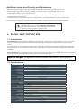 3
3
-
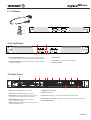 4
4
-
 5
5
-
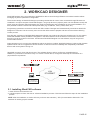 6
6
-
 7
7
-
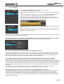 8
8
-
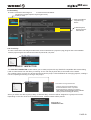 9
9
-
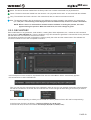 10
10
-
 11
11
-
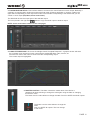 12
12
-
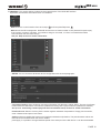 13
13
-
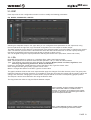 14
14
-
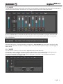 15
15
-
 16
16
-
 17
17
-
 18
18
-
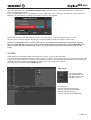 19
19
-
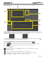 20
20
-
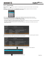 21
21
-
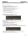 22
22
-
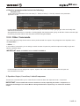 23
23
-
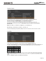 24
24
-
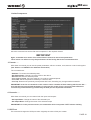 25
25
-
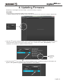 26
26
-
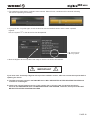 27
27
-
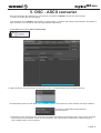 28
28
-
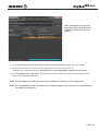 29
29
-
 30
30
-
 31
31
-
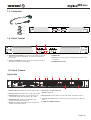 32
32
-
 33
33
-
 34
34
-
 35
35
-
 36
36
-
 37
37
-
 38
38
-
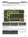 39
39
-
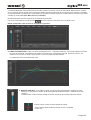 40
40
-
 41
41
-
 42
42
-
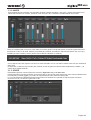 43
43
-
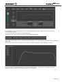 44
44
-
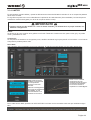 45
45
-
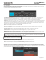 46
46
-
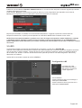 47
47
-
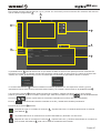 48
48
-
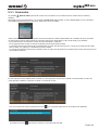 49
49
-
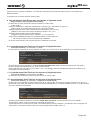 50
50
-
 51
51
-
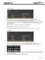 52
52
-
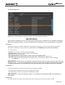 53
53
-
 54
54
-
 55
55
-
 56
56
-
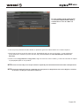 57
57
-
 58
58


Work Pro Digiline Serie Manual de usuario
- Categoría
- Controladores de DJ
- Tipo
- Manual de usuario
- Este manual también es adecuado para
en otros idiomas
- English: Work Pro Digiline Serie User manual
Artículos relacionados


Otros documentos
-
Work-pro Digiline 8 Manual de usuario
-
-
TC Electronic P2 - LEVEL PILOT INCL. DIGITAL BYPASS El manual del propietario
-
-
-
Work-pro BLR2 A PLUS MKII Manual de usuario
-
-
-
Work-pro SPS 8 Manual de usuario
-