
T WB-48
We invite you
to read the user
manual before
operating your
equipment.
Lo invitamos a leer
el manual del
usuario antes de
operar su equipo.
Mesa de trabajo
1,200 x 600
Work bench
mm

ASSEMBLY
WARNING
Adults assembly required.
During assembly, keep all parts away from children.
Choking hazard-small part.
Check regularly to ensure all fasteners are tight.
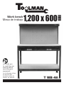
PARTS
• If any parts are missing, broken, damaged or worn, stop
using this product until repairs are mede and factory
replacement parts are installed. You may obtain
replacement parts by calling 01 800 70 56682 KNOVA
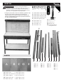
AB D EC
A Base board (1,195 x 590 x 9 mm)
B Counter top board (1,195 x 590 x 6 mm)
C Top board (1,197 x 218 x 6 mm)
D Hole board (1,190 x 560 x 3 mm)
E Drawer board (1,085 x 456 x 6 mm)
10 Hook (x 12)
11 Plate (x 1)
12 Handle (x 2)
13 Triangle plastic parts (x 4)
17
16
25
14 15 18 19 20 21 22 23 24 26
14 (x 2)
15 (x 2)
16 (x 1)
17 (x 1)
18 (x 4)
19 (x 4)
20 (x 2)
21 (x 2)
22 (x 2)
23 (x 1)
24 (x 1)
25 (x 1)
26 (x 1)
12345678910
11
12
13
1 Screw M6 x 0.55 in (x 8)
2 Screw M4 x 0.47 in (x 6)
3 Screw M6 x 0.39 in (x 63)
4 Screw M4 x 0.39 in (x 8)
5 Trapping screw (x 8)
6 Nut M6 (x 71)
7 Nut M4 (x 14)
8 Gasket M6 (x 71)
9 Gasket M4 (x 14)

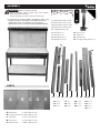
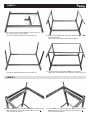
PART 1
2) Fit the transverse bar (14) between the brackets of the
perforated board. (using 2 pcs 3 screws M6 x 0.39 in)
3) Use the screw M6 x 0.55 in to x the perforated board
to the frame. (using 3 pcs 1 screws M6 x 0.55 in)
4) Position the left and right support brackets (16) and (17)
on the work table corners, (using 4 pcs 3 screws
M6 x 0.39 in)
16
5) Fit a cross bar (18) between the two upper support
brackets. (using 4 pcs screws 3 M6 x 0.39 in)
6) Mount the board (C) on the top of the frame.
(using 4 pcs trapping screws)
17
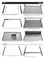
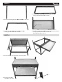
PART 2
7) Put the left and right feet (21) and (21) on a at surface. 8) Joining the two real legs with a transverse bar (18).
(using 4 pcs 3 screws M6 x 0.39 in)
1) Put the right and left brackets (15) and (15)
of the perforated board on a at surface

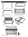
PART 2
9) Fix another corssbar (14) on top the top of the feet.
(using 4 pcs 3 screws M6 x 0.39 in)
10) Fix the four side rail (19) on the real legs.
(using 8 pcs 3 screws M6 x 0.39 in)
11) Fix the left and right front feet (20) and (20) on the side
rails. (using 8 pcs 3 screws M6 x 0.39 in)
12) Fix two cross bars (18) between the front feet.
(using 8 pcs 3 screws M6 x 0.39 in)
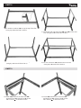
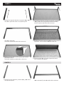
PART 3
13) Install (26) between the front foot (20)
and back foot (21) (using 4 pcs 3 screws
M6 x 0.39 in) on the left of frame
14) Install (25) between the front foot (20)
and back foot (21) (using 4 pcs 3 screws
M6 x 0.39 in) on the left of frame

PART 3
15) Put the left and right plate (22) and (22) on the oor
16) Install the plate (24) between (22) and (22)
(using 4 pcs 3 screws M6 x 0.39 in)
17) Install another plate (23) between (22) and (22)
(using 4 pcs 3 screws M6 x 0.39 in)
18) Install the drawer board (E) and two handles to the drawer
(using 8 pcs 4 screws M4 x 0.39 in and
6 pcs 2 screw M4 x 0.47 in)
M4 x 0.47 in
M4 x 0.39 in
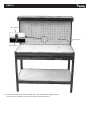
PART 4
19) Put the drawer into the frame of the work table.
20) Put the board (A)
and (B) on the frame.
13

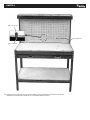
PART 4
M6 x 0.55 in
M6 x 0.39 in
M6 x 0.39 in
M6 x 0.55 in
21) Install the small plate on the work table and x the metal reinforcing perforation.
(using 5 pcs screws M6 x 0.39 in and 5 pcs 1 screws M6 x 0.55 in)

MONTAJE
Requiere montaje de adultos.
Durante el montaje, mantenga todas las piezas fuera
del alcance de los niños. Peligro de asxia: pieza
pequeña. Verique regularmente para asegurarse de
que todos los sujetadores estén apretados.
PARTES
• Si alguna pieza falta, está rota, dañada o gastada, deje
de usar este producto hasta que se realicen las
reparaciones y se instalen las piezas de repuesto de
fábrica. Puede obtener piezas de repuesto llamando al
01 800 70 56682 KNOVA
AB D EC
A Tablero base (1,195 x 590 x 9 mm)
B Tablero de encimera (1,195 x 590 x 6 mm)
C Tablero superior (1,197 x 218 x 6 mm)
D Tablero perforado (1,190 x 560 x 3 mm)
E Tablero del cajón (1,085 x 456 x 6 mm)
ADVERTENCIA
1 Tornillo M6 x 13.97 mm (x 8)
2 Tornillo M4 x 11.93 mm (x 6)
3 Tornillo M6 x 9.90 mm (x 63)
4 Tornillo M4 x 9.90 mm (x 8)
5 Tornillo de sujeción (x 8)
6 Tuerca M6 (x 71)
7 Tuerca M4 (x 14)
8 Junta M6 (x 71)
9 Junta M4 (x 14)
10 Gancho (x 12)
11 Lamina (x 1)
12 Manija (x 2)
13 Piezas de plástico
triangulares (x 4)
17
16
25
14 15 18 19 20 21 22 23 24 26
14 (x 2)
15 (x 2)
16 (x 1)
17 (x 1)
18 (x 4)
19 (x 4)
20 (x 2)
21 (x 2)
22 (x 2)
23 (x 1)
24 (x 1)
25 (x 1)
26 (x 1)
12345678910
11
12
13

PARTE 1
2) Colocar la barra transversal (14) entre los soportes
del tablero perforado.
(utilizando 2 piezas 3 tornillos M6 x 9.90 mm)
3) Utilice el tornillo M6 x 13.97 mm Para jar la placa
perforada al marco.
(utilizando 3 piezas 1 tornillos M6 x 13.97 mm)
4) Coloque los soportes de soporte izquierdo y derecho
(16) y (17) en las esquinas de la mesa de trabajo
(usando 4 piezas 3 tornillos M6 x 9.90 mm)
16
5) Coloque una barra transversal (18) entre los dos soportes
superiores. (con 4 tornillos de 3 M6 x 9.90 mm)
6) Monte la placa (C) en la parte superior del marco.
(con 4 tornillos de sujeción)
17
PARTE 2
7) Coloque los pies izquierdo y derecho (21) y (21) sobre
una supercie plana.
8) Uniendo las dos patas reales con una barra transversal
(18). (utilizando 4 piezas 3 tornillos M6 x 9.90 mm)
1) Coloque los soportes derecho e izquierdo (15) y (15)
del tablero perforado sobre una supercie plana

PARTE 2
9) Fije otra barra transversal (14) en la parte superior
de la parte superior de las patas
(utilizando 4 piezas 3 tornillos M6 x 9.90 mm)
10) Fije la barandilla de cuatro lados (19) en las patas reales.
(utilizando 8 piezas 3 tornillos M6 x 9.90 mm)
11) Fije las patas delanteras izquierda y derecha (20) y (20)
en el lateral rieles.
(utilizando 8 piezas 3 tornillos M6 x 9.90 mm)
12) Fije dos barras transversales (18) entre las patas
delanteras. (utilizando 8 piezas 3 tornillos M6 x 9.90 mm)
PARTE 3
13) Instale (26) entre la pata delantera (20) y la pata trasera
(21) (utilizando 4 piezas 3 tornillos M6 x 9.90 mm)
A la izquierda del marco.
14) Instale (25) entre la pata delantera (20) y la pata trasera
(21) (utilizando 4 piezas 3 tornillos M6 x 9.90 mm)
A la izquierda del marco.

PARTE 3
15) Coloque la placa izquierda y derecha (22) y (22)
en el suelo
16) Instale la placa (24) entre (22) y (22)
(utilizando 4 piezas 3 tornillos M6 x 9.90 mm)
17) Instale otra placa (23) entre (22) y (22)
(utilizando 4 piezas 3 tornillos M6 x 9.90 mm)
18) Instale la placa del cajón (E) y las dos asas en el cajón
(utilizando 8 piezas 4 tornillos M4 x 9.90 mm
Y 6 piezas 2 tornillos M4 x 11.93 mm)
M4 x 11.93 mm
M4 x 9.90 mm
PARTE 4
19) Coloque el cajón en el marco de la mesa de trabajo.
20) Coloque la tabla (A)
y (B) en el marco.
13

PARTE 4
M6 x 15.97 mm
M6 x 9.90 mm
M6 x 9.90 mm
M6 x 13.97 mm
21) Instale la placa pequeña en la mesa de trabajo y je la perforación de refuerzo de metal.
(utilizando 5 tornillos M6 x 9.90 mm y 5 tornillos 1 M6 x 9.90 mm)

www.knova.com.mx
-
 1
1
-
 2
2
-
 3
3
-
 4
4
-
 5
5
-
 6
6
-
 7
7
-
 8
8
-
 9
9
-
 10
10
-
 11
11
-
 12
12


KNOVA KN WB-48 El manual del propietario
- Tipo
- El manual del propietario
- Este manual también es adecuado para
Otros documentos
-
Samsung ACCUVIX A30 Manual de usuario
-
Samsung SONOACE R7 Manual de usuario
-
CARLO GAVAZZI RVPM1200500FP El manual del propietario
-
ESAB M3® Plasma Plasmarc PT-36 Plasma Arc Cutting Data Manual de usuario
-
 Sangean Electronics PT 10 Manual de usuario
-
LD Systems DSP 44 K RACK Manual de usuario
-
Trevi MB 729 Especificación
-
Electrolux SBB800S-1 Guía de instalación
-
Premier RD-910D Manual de usuario
-
Malaguti KYMCO 150 - KY - ML 15 Manual de usuario
