
ISTRUZIONI DI MONTAGGIO
ASSEMBLY ISTRUCTIONS
NOTICE DE MON TAGE
MONTAGEANLEITUNGEN
INSTRUCCIONES DE MONTAJE
Code MD.K.001 Rev 08 Edition 12/2015
advanced mobular stair system
MC
Mod. VECTOR 70
Mod. VECTOR 76
Mod. VECTOR 83

Via C.Colombo, 22/A - 42046 - Reggiolo - Reggio Emilia - Italy
Tel. +39 - 0522-211811 - Fax +39 - 0522-97 31 39
www.ehleva.com ehleva@ehleva.it
By Mobirolo S.p.A.
- 2 -
VECTOR 70 - 83 - 76
- VECTOR 70 - VECTOR 83- VECTOR 76-
advanced mobular stair system
INDICE
PARTE 1. ................................................................... Pag.4
Componenti VECTOR 70 - 83- 76. ...................... “ 4
PARTE 2. ................................................................... Pag.8
Impostazione VECTOR 70 - 83- 76 . .................... “ 8
Rilievo altezza utile ................................................. “ 10
Calcolo della pedata .............................................. “ 12
Calcolo della alzata................................................ “ 14
Configurazioni ......................................................... “ 18
Configurazioni a “L”. ............................................. “ 19
Configurazioni a “U”. ............................................. “ 20
Tracciatura ............................................................... “. 22
Preparazione colonne e gradini .......................... “ 23
Montaggio gradini ................................................... “ 25
Montaggio Pilastro e Mensola.............................. “ 36
Verifica e montaggio colonne supplementari ... “ 40
Montaggio corrimano ............................................. “ 42
Montaggio cavi ringhiera ....................................... “ 45
Completamento e verifiche ................................... “ 46
CONTENTS
PART 1. ............................................................................. Pag. 4
Components VECTOR 70 - 83- 76. .............................. “ 4
PART 2. ............................................................................. Pag. 8
Configuration VECTOR 70 - 83- 76 . ............................ “ 8
Useful height measurement .......................................... “ 10
Calculating the tread ....................................................... “ 12
Calculating the rise.................................... “ 14
Configuration ................................................................... “ 18
Configuration “L”. ......................................................... “ 19
Configuration “U”. ......................................................... “ 20
Traking .............................................................................. “. 22
Preparing columns and steps ....................................... “ 23
Assembling the steps ..................................................... “ 25
Mounting the column and bracket......................... .“ 36
Checking and mounting additional columns ............... “ 40
Assembling the handrail................................................. “ 42
Assembling handrail cables .......................................... “ 45
Completion and checks .................................................. “ 46
SOMMAIRE
PARTIE 1............................................................................................. Page. 4
Composants VECTOR 70 - 83- 76 ................................................. “ 4
PARTIE 2............................................................................................. Page. 8
Configuration VECTOR 70 - 83- 76 . ............................................... “ 8
Mesure de la hauteur utile ................................................................ “ 10
Calcul du giron ................................................................................... “ 12
Calcul de la hauteur de marche ...................................................... “ 14
Configurations .................................................................................. “ 18
Configurations “L”. .......................................................................... “ 19
Configurations “U”. .......................................................................... “ 20
Tracé ................................................................................................... “. 22
Préparation des colonnes et des marches .................................... “ 23
Montage des marches ...................................................................... “ 25
Montage du Mât et de la Console de Fixation au mur ................... “ 36
Contrôle et montage des colonnes supplémentaires .................. “ 40
Montage de la main courante ........................................................... “ 42
Montage des câbles de la rampe .................................................... “ 45
Compléments et contrôles ............................................................... “ 46

Via C.Colombo, 22/A - 42046 - Reggiolo - Reggio Emilia - Italy
Tel. +39 - 0522-211811 - Fax +39 - 0522-97 31 39
www.ehleva.com ehleva@ehleva.it
By Mobirolo S.p.A.
- 3 -
VECTOR 70 - 83 - 76
- VECTOR 70 - VECTOR 83- VECTOR 76-
advanced mobular stair system
INHALT
TEIL 1. ............................................................................................................S. 4
Bauteile VECTOR 70 - 83- 76. ....................................................................“ 4
TEIL 2. ............................................................................................................S. 8
Einstellung VECTOR 70 - 83- 76 . .............................................................. “ 8
Messung der Nutzhöhe ................................................................................ “ 10
Berechnung des Auftritts ..............................................................................“ 12
Berechnung der Steigung ............................................................................“ 14
Treppengestaltungen ..................................................................................“ 18
“L”-förmige Treppengestaltungen .............................................................“ 19
“U”-förmige Treppengestaltungen. ............................................................ “ 20
Markierung .....................................................................................................“. 22
Vorbereitung der Geländerstangen und Stufen .........................................“ 23
Montage der Stufen .......................................................................................“ 25
Montage von Pfosten und Stützkonsole ..................................................... “ 36
Prüfung und Montage der zusätzlichen Geländerstangen ......................“ 40
Montage des Handlaufs .............................................................................. “ 42
Montage der Geländerseile ......................................................................... “ 45
Vervollständigung und Prüfungen ..............................................................“ 46
ÍNDICE
PARTE 1. Pág. 4
Componentes VECT OR 70 - 83- 76. “ 4
PARTE 2. Pág 8
Colocación VECTOR 70 - 83- 76 . “ 8
Determinación de la altura útil “ 10
Cálculo de la huella “ 12
Cálculo de la contrahuella “ 14
Configuraciones “ 18
Configuraciones en “L”. “ 19
Configuraciones en “U”. “ 20
Trazado “. 22
Preparación de las columnas y los peldaños “ 23
Montaje de los peldaños “ 25
Montaje del pilar y de la ménsula “ 36
Comprobación y montaje de las columnas suplementarias “ 40
Montaje del pasamanos “ 42
Montaje de los cables de la barandilla “ 45
Acabado y comprobaciones “ 46

Via C.Colombo, 22/A - 42046 - Reggiolo - Reggio Emilia - Italy
Tel. +39 - 0522-211811 - Fax +39 - 0522-97 31 39
www.ehleva.com ehleva@ehleva.it
By Mobirolo S.p.A.
- 4 -
VECTOR 70 - 83 - 76
- VECTOR 70 - VECTOR 83- VECTOR 76-
advanced mobular stair system
Prima di procedere con le varie fasi di montaggio, vuotare il cartone e posizionare tutti i particolari suuna superficie
piana, verificare la presenza di tutti i componenti come da distinta allegata, che il numero dei pezzi sia conforme a
quanto riportato per le due configurazioni, di scala, ad “L” e ad “U” e che non vi siano parti danneggiate.
PARTE 1; PART 1; PARTIE 1; TEIL 1 ; PARTE 1
COMPONENTI Mod. VECTOR 70 - VECTOR 83 - VECTOR 76 -
Before proceeding to the various assembly stages, empty the cardboard package and arrange all parts on a flat
surface to check that all components included in the list attached are present, that the number of components
matches the indications of both the “L” and “U” configurations of the stairs and that no damaged parts are present.
COMPONENTS Mod. VECTOR 70 - VECTOR 83 - VECTOR 76 -
Avant de procéder aux différentes phases de montage, retirer tous les éléments du carton et les disposer sur une
surface plane. Contrôler que tous les composants sont présents en se référant à liste d’accompagnement, contrôler
que le nombre de pièces est conforme aux indications reportées pour les deux configurations en “L” et en “U” de
l’escalier et vérifier qu’aucun élément ne soit endommagé.
COMPOSANT Mod. VECTOR 70 - VECTOR 83 - VECTOR 76 -
Vor Beginn der verschiedenen Montagephasen, den Karton entleeren, alle Teile auf eine ebene Fläche legen und
prüfen, dass alle Bauteile laut beiliegender Stückliste vorhanden sind, dass die Menge der Teile denAngaben für die
beiden “L”- und “U”-förmigen Treppengestaltungen entspricht und dass keine Teile beschädigt sind
BAUTEILE AUS Mod. VECTOR 70 - VECTOR 83 - VECTOR 76 -
Antes de empezar con las diferentes fases del montaje, vacíe el cartón y coloque todos los elementos sobre una
superficie plana, compruebe que están todos los componentes que se indican en la lista adjunta, que el número de
piezas coincide con lo que se indica para ambas configuraciones de escalera, en “L” y en “U” y que no haya partes
dañadas.
COMPONENTS Mod. VECTOR 70 - VECTOR 83 - VECTOR 76 -
FORMASCALA
STAIRSHAPE
FORMEDEL’ESCALIER
TREPPENFORM
FORMADELAESCALERA
Rif. Dis. N. pz.
Rif. Dis. N. pz.
L15
L22 0 1 2
L23 0 1 2
76-83 6 5 5
FORMASCALA
STAIRSHAPE
FORMEDEL’ESCALIER
TREPPENFORM
FORMADELAESCALERA
|
L21 0 1 2
70 5 4 4
|

Via C.Colombo, 22/A - 42046 - Reggiolo - Reggio Emilia - Italy
Tel. +39 - 0522-211811 - Fax +39 - 0522-97 31 39
www.ehleva.com ehleva@ehleva.it
By Mobirolo S.p.A.
- 5 -
VECTOR 70 - 83 - 76
- VECTOR 70 - VECTOR 83- VECTOR 76-
advanced mobular stair system
Mod. VECTORO 70 - VECTOR 83 - VECTOR 76 -
Rif. Dis. N. pz.
Rif. Dis. N. pz.
K133 1 1 1
K60 16 32 48
K65 13 12 10
K63 13 11 9
K71 5 4 4
1160 mm
Ø 22 mm
4.2x19
K77 5 4 4
K80 30 30 30
K82 0 1 2
K84 Lungh.6500 mm 7 7 7
K38 1 1 1
K36
K36
K36
K18
x 16
K66
D03 1 1 1
D04 1 1 1
MPS-0089 13 11 9
210-0077 2 4 6
L20 12 9 6
|
|
x 7

Via C.Colombo, 22/A - 42046 - Reggiolo - Reggio Emilia - Italy
Tel. +39 - 0522-211811 - Fax +39 - 0522-97 31 39
www.ehleva.com ehleva@ehleva.it
By Mobirolo S.p.A.
- 6 -
VECTOR 70 - 83 - 76
- VECTOR 70 - VECTOR 83- VECTOR 76-
advanced mobular stair system
Rif. Dis. N. pz. Rif. Dis. N. pz.
K102 1 1 1
K101 10 10 10
K103 1 1 1
K121 1 1 1
K420 1 1 1
1100 mm
Ø 22 mm
K125 0 1 2
M16x30
K120
K119
K104
K126
K127
438100
710
11 11 11
P90 1 1 1
K421 1 1 1
||

Via C.Colombo, 22/A - 42046 - Reggiolo - Reggio Emilia - Italy
Tel. +39 - 0522-211811 - Fax +39 - 0522-97 31 39
www.ehleva.com ehleva@ehleva.it
By Mobirolo S.p.A.
- 7 -
VECTOR 70 - 83 - 76
- VECTOR 70 - VECTOR 83- VECTOR 76-
advanced mobular stair system
Rif. Dis. N. pz. Rif. Dis. N. pz.
2 2 2
P110 13 11 9
B207 2 2 2
B203 27 23 23
B205 48 48 48
P105 23 23 23
P107 27 23 23
P106a 22 22 22
P106 143 143 143
K129
K130
K131
K23
B200
B301
431510
000
1 1 1
2 2 2
x 4
x 2
x 2
x 6
x 1
x 4
x 12
CHL-0
309B201Z
476070
018
1 1 1
||

Via C.Colombo, 22/A - 42046 - Reggiolo - Reggio Emilia - Italy
Tel. +39 - 0522-211811 - Fax +39 - 0522-97 31 39
www.ehleva.com ehleva@ehleva.it
By Mobirolo S.p.A.
- 8 -
VECTOR 70 - 83 - 76
- VECTOR 70 - VECTOR 83- VECTOR 76-
advanced mobular stair system
IMPOSTAZIONE VECTOR
Vengono denominate “scale modulari” in quanto è possibile regolare l’alzata “A” e la pedata “P” in funzione dello
spazio a disposizione.
Con la sigla “VECTOR 70”, si intende il modello di scala con larghezza del gradino pari a 700 mm.
Con la sigla “VECTOR 76”, si intende il modello di scala sempre con larghezza del gradino pari a 760 mm.
Con la sigla “VECTOR 83”, si intende il modello di scala sempre con larghezza del gradino pari a 830 mm.
La tipologia e le istruzioni per un corretto montaggio sono identiche.
La scala può essere addossata ad una parete o ambientata in uno spazio aperto.
Nel primo caso, essa monterà la ringhiera solo dallato interno e opposto alla parete, con la misura di passaggio che
può essere rilevata dallo schema di fig. b.
Nel caso in cui sia necessario montare la ringhiera su entrambi i lati, il passaggio viene evidenziato in fig. a.
L’ambientazione e lo spazio a disposizione determinano inoltre il senso di salita, che può essere destro o sinistro e
la configurazione vera e propria della scala, con una forma chiamata a “L” o ad “U”, come viene illustrato nelle pagine
successive.
PARTE 2; PART 2; PARTIE 2; TEIL 2; PARTE 2
CONFIGURATION VECTOR
These are called “modular stairs” because the rise “A” and tread“P” may be adjusted according to the availabe space
“VECTOR 70” label identifies the stair model having a 700 mm step width
“VECTOR 76” label identifies the stair model having a 760 mmstep width.
“VECTOR 83” label identifies the stair model having a 830 mm step width.
The type and instructions for a correct assembly are identical.
The staircase may lean on a wall or be placed in an open environment.
In the first case, the banister will be mounted only on the inner side opposite the wall, and the gangway size may be
derived fromfigure b.
If the banister needs to be mounted on both sides, the gangway is highlighted in fig. a.
Moreover, the location and available space determine the climbing directions, which may be right- or left-oriented,
andthe actual staircase configuration, according to an “L-” or “U-”shaped configuration, as illustrated in the following
pages.
CONFIGURATION VECTOR
Ils sont appelés “escaliers modulaires” car il est possible d’ajuster la hauteur de marche “A” et le giron “P” en
fonctionde l’espace à disposition.
Le sigle “VECTOR 70” se réfère au modèle d’escalier dont les marches ont une largeur de 700 mm.
Le sigle “VECTOR 76” se réfère au modèle d’escalier dont les marches ont une largeur de 760 mm.
Le sigle “VECTOR 83” se réfère au modèle d’escalier dont les marches ont une largeur de 830 mm.
La typologie et les instructions à suivre pour un bon montage sont identiques.
L’escalier peut être appuyé contre un mur ou placé dans un espace ouvert.
Dans le premier cas, la balustrade sera montée seulement sur le côté interne opposé au mur et la mesure
d’emmarchement peut être déterminée par le schéma fig. b.
S’il est nécessaire de monter la balustrade des deux côtés, l’emmarchement est indiqué fig. a.
L’agencement et l’espace à disposition déterminent aussi le sens de montée qui peut être à droite ou à gauche,
ainsi que la configuration finale de l’escalier à forme en “L” ou en “U”, comme illustré sur les pages suivantes.

Via C.Colombo, 22/A - 42046 - Reggiolo - Reggio Emilia - Italy
Tel. +39 - 0522-211811 - Fax +39 - 0522-97 31 39
www.ehleva.com ehleva@ehleva.it
By Mobirolo S.p.A.
- 9 -
VECTOR 70 - 83 - 76
- VECTOR 70 - VECTOR 83- VECTOR 76-
advanced mobular stair system
EINSTELLUNG VECTOR
Sie werdenals “Modulbautreppen” bezeichnet, da ihre Steigung “A” und ihrAuftritt “P” in Funktiondes verfügbaren
Platzes einstellbar sind.
“VECTOR 70” ist das Treppenmodell mit 700 mm breiten Stufen.
“VECTOR 76” ist das Treppenmodell mit 760 mm breiten Stufen.
“VECTOR 83” ist das Treppenmodell mit 830 mm breiten Stufen.
Die korrekte Montage erfolgt in identischer Weise mit den gleichen Anleitungen.
Die Treppe kann gegen eine Wand oder in einen offenen Raummontiert werden.
Imersten Fallwird das Geländer nur an der der Wand gegenüber liegenden Innenseite montiert; das entsprechende
Durchgangsmaß ist im Schema b enthalten.
Im Falle einer Geländermontage an beiden Seiten, ist der Durchgang in der Abb. a dargestellt.
Die Gestalt des Raums und der verfügbare Freiraum bestimmendie “L”- oder “U”-förmige Aufstiegsrichtung, wie in
den folgenden Seiten dargestellt.
COLOCACIÓN VECTOR
Se denominan “escaleras modulares” porque es posible regular la contrahuella “A” y la huella “P” en función del
espacio disponible.
Con la sigla “VECTOR 70”, se designa el modelo de escalera con unancho de peldaño de 700 mm.
Con la sigla “VECTOR 76”, se designa el modelo de escalera con unancho de peldaño de 760 mm.
Con la sigla “VECTOR 83”, se designa el modelo de escalera con un ancho de peldaño de 830 mm.
El tipo y las instrucciones para el montaje correcto son idénticos.
La escalera se puede adosar a una pared o ambientarse en un espacio abierto.
En el primer caso, la barandilla se montará en el lado interno y opuesto a la pared, con la medida de paso que se
puede determinar a partir del esquema de la fig. b.
En caso de que sea necesario montar la barandilla a ambos lados, se indica en la fig. a.
La ambientación y el espacio disponible determinan, además, el sentido de subida, que puede ser izquierdo o
derecho, así como la verdadera configuración de la escalera, con unaforma llamada en “L” o en “U, como se ilustra
en las páginas siguientes.
Fig.a Fig.b
VECTOR 70 - 742.5
10 - 40 mm
VECTOR 76 - 802.5
VECTOR 83 - 872.5
VECTOR 70 - 700
VECTOR 76 - 760
VECTOR 83 - 830
Mod. VECTOR 70 Largh. 740 mm
Mod. VECTOR 76 Largh. 800 mm
Mod. VECTOR 83 Largh. 870 mm
VECTOR 70 - 700
VECTOR 76 - 760
VECTOR 83 - 830
VECTOR 70 - 785
VECTOR 76 - 845
VECTOR 83 - 915

Via C.Colombo, 22/A - 42046 - Reggiolo - Reggio Emilia - Italy
Tel. +39 - 0522-211811 - Fax +39 - 0522-97 31 39
www.ehleva.com ehleva@ehleva.it
By Mobirolo S.p.A.
- 10 -
VECTOR 70 - 83 - 76
- VECTOR 70 - VECTOR 83- VECTOR 76-
advanced mobular stair system
RILIEVO ALTEZZA UTILE
In fig. 1, sono evidenziate le misure che occorre stabilire.
“H” Misura altezza (fig. 2)
“P” Misura pedata, calcolata secondo le indicazioni riportate a pag. 13
“A” Misura alzata, da rilevare nella “Tabella “A” di pag. 15-16-17
N.B. Tutte le misure riportate nel manuale sono in “mm” (millimetri)
Rilevare la distanza da pavimento superiore a pavimento inferiore “H”.
La quota risultante da tale operazione ha rilevanza importante in quanto fissa la misura dell’alzata “A”.
La misura “H” deve essere ricercata nell’apposita casella della “tabella A” alle pagine 15-16-17.
Una volta trovata la misura dell’altezza “H”, nelle caselle a fianco si può rilevare il valore dell’alzata “A”, e quante ne
occorrono per raggiungere la nostra altezza. (Fig. 2)
Si segua comunque dettagliata spiegazione nelle pagine successive.
USEFUL HEIGHT MEASUREMENT
The measures that need to be assessed are reported in fig. 1.
“H” Height (fig. 2)
“P” Tread size, calculated according to the instructions reported on page 13
“A” Rise size to be defined based on “Table “A” on pages 15-16-17
N.B. All measures reported in the manual are in “mm” (millimetres)
Measure the distance between upper and lower floor “H”.
The measure assessed thanks to this operation plays an important role since it sets the rise size “A”.
The size “H” needs to be identified in the dedicated box of “table A” on pages 15-16-17.
After having identified the “H” height, the
adjacent boxes report the rise value “A” and how many steps are needed to achieve the desired height. (Fig. 2)
However, follow the detailed explanation on the following pages.
MESURE DE LA HAUTEUR UTILE
La fig. 1 indique les mesures qu’il faut établir.
“H” Mesure de la hauteur (fig. 2)
“P” Mesure du giron, calculée selon les indications reportées page 13
“A” Mesure de la hauteur de marche à déterminer sur le “Tableau A” pages 15-16-17
N.B. Toutes les mesures indiquées dans le manuel sont en “mm” (millimètres)
Mesurer la hauteur entre le plancher supérieur et le plancher inférieur “H”.
La hauteur résultant de cette opération est fondamentale car elle fixe la mesure de la hauteur de marche “A”.
La mesure “H” doit être recherchée dans la case du “Tableau A” aux pages 15-16-17.
Après avoir trouvé la mesure de la hauteur “H”, les cases à côté permettent d’établir la valeur de la hauteur de
marche “A” et le nombre de marches nécessaires pour atteindre cette hauteur. (Fig. 2)
Il faut suivre toutefois toujours suivre les explications détaillées reportées aux pages suivantes

Via C.Colombo, 22/A - 42046 - Reggiolo - Reggio Emilia - Italy
Tel. +39 - 0522-211811 - Fax +39 - 0522-97 31 39
www.ehleva.com ehleva@ehleva.it
By Mobirolo S.p.A.
- 11 -
VECTOR 70 - 83 - 76
- VECTOR 70 - VECTOR 83- VECTOR 76-
advanced mobular stair system
Fig.2
H
Fig.1
P
A
MESSUNG DER NUTZHÖHE
Die Abb. 1 zeigt, welche Maße zu bestimmen sind.
“H” Höhenmaß (Abb. 2)
“P” Auftrittsmaß, laut Angaben auf S. 13 zu berechnen.
“A” Steigungsmaß, aus der “Tabelle “A” auf S. 15-16-17 zu entnehmen.
Merke: Alle im Handbuch angegebenen Maße sind in “mm” (Millimetern) ausgedrückt.
Den Abstand vom Boden zur Decke “H” messen.
Dieses Maß ist sehr wichtig, da es das Steigungsmaß bestimmt “A”.
Das Maß “H” ist dem entsprechenden Kästchen der “Tabelle A” auf den Seiten 15-16-17 zu entnehmen.
Nachdem dieses Maß “H” gefundenwurde, kann
aus den daneben stehenden Kästchen das
Steigungsmaß “A” sowie die zum Erreichen der
Höhe erforderlichen Stufenmenge entnommen
werden (Abb. 2).
Bitte auf jedenFall die ausführlichen Erläuterungen
auf den folgendenSeiten befolgen.
DETERMINACIÓN DE LA
ALTURA ÚTIL
En la fig. 1, se indican las medidas que hay que
establecer.
“H” Medida de la altura (fig. 2)
“P” Medida de la huella, calculada según
las indicaciones de la pág. 13
“A” Medida de la contrahuella, a
determinar en la “Tabla “A”” de las
págs.15-16-17
NOTA: Todas las medidas que se
indican en el manual son en milímetros (mm).
Determine la distancia del pavimento superior al
pavimento inferior, “H”.
La altura resultante de esta operación es un dato
importante, puesto que fija la medida de la
contrahuella “A”.
La medida “H” debe buscarse en la celda
adecuada de la “tabla A” enlas páginas 15-16-
17.
Una vez encontrada la medida de la altura “H”,
enlas celdas de allado se puede obtener el valor
de la contrahuella “A”, y cuántas son necesarias
para alcanzar nuestra altura. (Fig. 2)
Encualquier caso, sígase la explicación detallada
de las páginas siguientes

Via C.Colombo, 22/A - 42046 - Reggiolo - Reggio Emilia - Italy
Tel. +39 - 0522-211811 - Fax +39 - 0522-97 31 39
www.ehleva.com ehleva@ehleva.it
By Mobirolo S.p.A.
- 12 -
VECTOR 70 - 83 - 76
- VECTOR 70 - VECTOR 83- VECTOR 76-
advanced mobular stair system
CALCOLO DELLA PEDATA
VECTOR 70 : P = 200 ÷ 230 max (mm),
VECTOR 76 : P = 220 ÷ 250 max (mm),
VECTOR 83 : P = 220 ÷ 250 max (mm),
P = Pedata
W = Lunghezza ingombro scala per configurazione a “L”
J = Larghezza ingombro scala per configurazione a “U”
ATTENZIONE
Le misure da riportare nelle sottostanti relazioni devono essere espresse in millimetri
CALCULATING THE TREAD
VECTOR 70 : P = 200 ÷ 230 max (mm),
VECTOR 76 : P = 220 ÷ 250 max (mm),
VECTOR 83 : P = 220 ÷ 250 max (mm),
P = Tread
W = Staircase length with “L” configuration
J = Staircase width with “U” configuration
WARNING
The measures to be reported in the documents below must be expressed in millimetres.
ATTENTION
Les mesures à reporter dans les relations suivantes doivent être en millimètres
CALCUL DU GIRON
P = Giron
W = Longueur de l’encombrement de l’escalier à configuration en “L”
J = Largeur de l’encombrement de l’escalier à configuration en “U”
VECTOR 70 : P = 200 ÷ 230 max (mm),
VECTOR 76 : P = 220 ÷ 250 max (mm),
VECTOR 83 : P = 220 ÷ 250 max (mm),
VECTOR 70 : P = 200 ÷ 230 max (mm),
VECTOR 76 : P = 220 ÷ 250 max (mm),
VECTOR 83 : P = 220 ÷ 250 max (mm),
ACHTUNG
Die in die unten stehenden Beziehungen einzutragenden Maße sind in Millimetern anzugeben.
BERECHNUNG DES AUFTRITTS
P = Auftritt
W = Länge des Treppenraumgrundrisses für “L”-förmige Treppengestaltung
J = LBreite des Treppenraumgrundrisses für “U”-förmige Treppengestaltung
VECTOR 70 : P = 200 ÷ 230 max (mm),
VECTOR 76 : P = 220 ÷ 250 max (mm),
VECTOR 83 : P = 220 ÷ 250 max (mm),
ATENCION
Las medidas que introducir en las relaciones siguientes se deben expresar en milímetros
P = Huella
W = Longitud de la escalera para la configuración en “L”.
J = Ancho de la escalera para la configuración en “U”.
CÁLCULO DE LA HUELLA

Via C.Colombo, 22/A - 42046 - Reggiolo - Reggio Emilia - Italy
Tel. +39 - 0522-211811 - Fax +39 - 0522-97 31 39
www.ehleva.com ehleva@ehleva.it
By Mobirolo S.p.A.
- 13 -
VECTOR 70 - 83 - 76
- VECTOR 70 - VECTOR 83- VECTOR 76-
advanced mobular stair system
Fig.c
DX
SX
DX
SX
W
Q
W
Q
L
J
n° G
n° G
n° G
P =
n° G - 1
J - 1720 (VECTOR83)
P =
n° G
W - 1140 (VECTOR83)
P =
n° G - 1
VECTOR 76-83
Config.
“U”
DX DX
W
Q
W
Q
L
J
n° G
n° G
n° G
W - 990
P =
n° G - 1
J - 1460
P =
n° G
n° G - 1
VECTOR 70
Config.
“L”
W - 1070 (VECTOR76)
W - 1140 (VECTOR83)
W - 1070 (VECTOR76)
P =
W - 990
J - 1580 (VECTOR76)

Via C.Colombo, 22/A - 42046 - Reggiolo - Reggio Emilia - Italy
Tel. +39 - 0522-211811 - Fax +39 - 0522-97 31 39
www.ehleva.com ehleva@ehleva.it
By Mobirolo S.p.A.
- 14 -
VECTOR 70 - 83 - 76
- VECTOR 70 - VECTOR 83- VECTOR 76-
advanced mobular stair system
CALCOLO DELLA ALZATA (tabella “A”)
Nella “tabella A” , sono riportate le misure dell’alzata infunzione dellaquota di altezza “H” rilevata precedentemente.
Sono inoltre riportati il numero di distanziali da montare K106, sempre in relazione all’altezza.
Esempio di lettura ed utilizzo della tebella: Altezza rilevata “H” 2390 mm
Nella riga corrispondente a 2390, si rileva che la scala sarà composta da 12 gradini e che si dovranno realizzare
n° 7 alzate da 180 mm e 5 da 185 mm. ( La prima alzata è da considerarsi sempre di 205 mm)
Per ottenere le suddette alzate occorre realizzare un pacco distanziali così composto:
per l’alzata da 180 mmunire quattro distanziali (due con spigoli arrotondati P106a e due normali P106)
per l’alzata da 185 mm unire cinque distanziali (due con spigoli arrotondati P106a e tre normali P106)
CALCULATING THE RISE (table “A”)
The “table A” below shows the values for the rise according to the “H” height measured previously. Moreover the
number of K106 spacers to be mounted is reported, also with reference to the height.
How to read and use the table: example. Measured height: “H” 2390 mm
The 2390 line shows that the staircase will be composed of 12 steps and that 7 180 mm rises and 5 185 mmrises
need to be created (the first rise is always 205 mm).
To create the rises described above, a spacer package must be installed including:
four spaces (two P106a with rounded corners and two normal P106) to achieve the 180 mmrise
five spacers (two P106a with rounded corners and three normal P106) to achieve the 185 mmrise
CALCUL DE LA HAUTEUR DE MARCHE (Tableau “A”)
Le “Tableau A” ci-dessous reporte les mesures de la hauteur de marche en fonction de la hauteur “H” mesurée
précédemment. Il reporte aussi le nombre de bagues intermédiaires à monter K106, toujours en fonction de la
hauteur.
Exemple de lecture et d’utilisation du tableau: Hauteur mesurée “H” 2390 mm. Sur la ligne correspondant à 2390,
on note que l’escalier sera constitué de 12 marches et qu’il faudra réaliser 7 hauteurs de marche de 180 mmet 5
hauteurs de marche de 185 mm. (La première hauteur de marche doit toujours être considérée de 205 mm)
Pour obtenir les hauteurs de marche susmentionnées, il faut réaliser un groupe de bagues intermédiaires constitué
ainsi: pour la hauteur de marche de 180 mm, assembler quatre bagues intermédiaires (deux à bords arrondis P106a
et deux normales P106) pour la hauteur de marche de 185 mm, assembler cinq bagues intermédiaires (deux à bords
arrondis P106a et trois normales P106)
BERECHNUNG DER STEIGUNG (Tabelle “A”)
Die unten stehende “Tabelle A” enthält die Maße der Steigung in Funktion des zuvor gemessenen
Höhenmaßes “H”. Außerdem ist die Menge der zu montierenden Distanzstücke K106 ebenfalls im
Verhältnis zur Höhe angegeben.
Beispiel zum Verständnis und zur Verwendung der Tabelle: Gemessene Höhe “H” 2390 mm
Die demMaß 2390 entsprechende Zeile gibt an, dass die Treppe aus 12 Stufen bestehen wird und dass 7 St. 180
mm- Steigungen und 5 St. Steigungen mit 185 mm zu fertigen sind. ( Die erste Steigung ist immer mit 205
mm zu berücksichtigen).
Um die obigen Steigungen zu erzielen, ist ein wie folgt zusammengesetztes Distanzstückepaket zu fertigen:
-für die 180 mm-Steigung vier Distanzstücke miteinander verbinden (zwei mit abgerundeten Kanten P106a und
zwei normale P106)
-für die 185 mm-Steigung fünf Distanzstücke miteinander verbinden (zwei mit abgerundeten Kanten
P106a und drei normale P106)
CÁLCULO DE LA CONTRAHUELLA (tabla “A”)
En la “tabla A” a continuación, se indican las medidas de la contrahuella en función de la altura “H” obtenida
anteriormente. Se indica también el número de espaciadores que montar, K106, siempre en relación a la altura.
Ejemplo de lectura y uso de la tabla: Altura determinada “H” 2390 mm
En la línea correspondiente a 2390, se determina que la escalera estará compuesta por 12 peldaños y que hay que
realizar 7 contrahuellas de 180 mm y 5 de 185 mm. ( La primera contrahuella debe considerarse siempre de 205
mm). Para obtener dichas contrahuellas hay que realizar un paquete de espaciadores compuesto como sigue:
para la contrahuella de 180 mm una cuatro espaciadores (dos con cantos redondeados P106a y dos normales
P106);
para la contrahuella de 185 mmuna cinco espaciadores (dos con cantos redondeados P106a y tres normales P106)

Via C.Colombo, 22/A - 42046 - Reggiolo - Reggio Emilia - Italy
Tel. +39 - 0522-211811 - Fax +39 - 0522-97 31 39
www.ehleva.com ehleva@ehleva.it
By Mobirolo S.p.A.
- 15 -
VECTOR 70 - 83 - 76
- VECTOR 70 - VECTOR 83- VECTOR 76-
advanced mobular stair system
N° Dist. 4 5 6 7 8
Alzata
H. G. 180 185 190 195 200
2365 12 12
2370 12 11 1
2375 12 10 2
2380 12 9 3
2385 12 8 4
2390 12 7 5
2395 12 6 6
2400 12 5 7
2405 12 4 8
2410 12 3 9
2415 12 2 10
2420 12 1 11
2425 12 12
2430 12 11 1
2435 12 10 2
2440 12 9 3
2445 12 8 4
2450 12 7 5
2455 12 6 6
2460 12 5 7
2465 12 4 8
2470 12 3 9
2475 12 2 10
2480 12 1 11
2485 12 12
2490 12 11 1
2495 12 10 2
2500 12 9 3
2505 12 8 4
2510 12 7 5
2515 12 6 6
2520 12 5 7
2525 12 4 8
2530 12 3 9
2535 12 2 10
2540 12 1 11
2545 12 12
2550 12 11 1
2555 12 10 2
2560 12 9 3
2565 12 8 4
2570 12 7 5
2575 12 6 6
2580 12 5 7
2585 12 4 8
2590 12 3 9
2595 12 2 10
2600 12 1 11
N° Dist. 8 9 10 11 12
Alzata
H. G. 200 205 210 215 220
2605 12 12
2610 12 11 1
2615 12 10 2
2620 12 9 3
2625 12 8 4
2630 12 7 5
2635 12 6 6
2640 12 5 7
2645 12 4 8
2650 12 3 9
2655 12 2 10
2660 12 1 11
2665 12 12
2670 12 11 1
2675 12 10 2
2680 12 9 3
2685 12 8 4
2690 12 7 5
2695 12 6 6
2700 12 5 7
2705 12 4 8
2710 12 3 9
2715 12 2 10
2720 12 1 11
2725 12 12
2730 12 11 1
2735 12 10 2
2740 12 9 3
2745 12 8 4
2750 12 7 5
2755 12 6 6
2760 12 5 7
2765 12 4 8
2770 12 3 9
2775 12 2 10
2780 12 1 11
2785 12 12
2790 12 11 1
2795 12 10 2
2800 12 9 3
2805 12 8 4
2810 12 7 5
2815 12 6 6
2820 12 5 7
2825 12 4 8
2830 12 3 9
2835 12 2 10
2840 12 1 11
“A” “A”
TABELLA “A”; TABLE “A” ; TABLEAU “A”; TABELLE “A”; TABLA “A”

Via C.Colombo, 22/A - 42046 - Reggiolo - Reggio Emilia - Italy
Tel. +39 - 0522-211811 - Fax +39 - 0522-97 31 39
www.ehleva.com ehleva@ehleva.it
By Mobirolo S.p.A.
- 16 -
VECTOR 70 - 83 - 76
- VECTOR 70 - VECTOR 83- VECTOR 76-
advanced mobular stair system
N° Dist. 12 13 14 15
Alzata
H. G. 220 225 230 235
2845 12 12
2850 12 11 1
2855 12 10 2
2860 12 9 3
2865 12 8 4
2870 12 7 5
2875 12 6 6
2880 12 5 7
2885 12 4 8
2890 12 3 9
2895 12 2 10
2900 12 1 11
2905 12 12
2910 12 11 1
2915 12 10 2
2920 12 9 3
2925 12 8 4
2930 12 7 5
2935 12 6 6
2940 12 5 7
2945 12 4 8
2950 12 3 9
2955 12 2 10
2960 12 1 11
2965 12 12
2970 12 11 1
2975 12 10 2
2980 12 9 3
2985 12 8 4
2990 12 7 5
2995 12 6 6
3000 12 5 7
3005 12 4 8
3010 12 3 9
3015 12 2 10
3020 12 1 11
3025 12 12
N° Dist. 11 12 13 14
Alzate
H. G. 215 220 225 230
3030 13 7 6
3035 13 6 7
3040 13 5 8
3045 13 4 9
3050 13 3 10
3055 13 2 11
3060 13 1 12
3065 13 13
3070 13 12 1
3075 13 11 2
3080 13 10 3
3085 13 9 4
3090 13 8 5
3095 13 7 6
3100 13 6 7
3105 13 5 8
3110 13 4 9
N° Dist. 11 12 13 14 15
Alzata
H. G. 215 220 225 230 235
3115 13 3 10
3120 13 2 11
3125 13 1 12
3130 13 13
3135 13 12 1
3140 13 11 2
3145 13 10 3
3150 13 9 4
3155 13 8 5
3160 13 7 6
3165 13 6 7
3170 13 5 8
3175 13 4 9
3180 13 3 10
3185 13 2 11
3190 13 1 12
3195 13 13
3200 13 12 1
3205 13 11 2
3210 13 10 3
3215 13 9 4
3220 13 8 5
3225 13 7 6
3230 13 6 7
3235 13 5 8
3240 13 4 9
3245 13 3 10
3250 13 2 11
3255 13 1 12
3260 13 13
N° Dist. 11 12 13 14
Alzate
H. G. 215 220 225 230
3265 14 4 10
3270 14 3 11
3275 14 2 12
3280 14 1 13
3285 14 14
3290 14 13 1
3295 14 12 2
3300 14 11 3
3305 14 10 4
3310 14 9 5
3315 14 8 6
3320 14 7 7
3325 14 6 8
3330 14 5 9
3335 14 4 10
3340 14 3 11
3345 14 2 12
3350 14 1 13
3355 14 14
3360 14 13 1
3365 14 12 2
3370 14 11 3
3375 14 10 4
“A” “A”
“A”
“A”

Via C.Colombo, 22/A - 42046 - Reggiolo - Reggio Emilia - Italy
Tel. +39 - 0522-211811 - Fax +39 - 0522-97 31 39
www.ehleva.com ehleva@ehleva.it
By Mobirolo S.p.A.
- 17 -
VECTOR 70 - 83 - 76
- VECTOR 70 - VECTOR 83- VECTOR 76-
advanced mobular stair system
N° Dist. 11 12 13 14 15
Alzata
H. G. 215 220 225 230 235
3380 14 9 5
3385 14 8 6
3390 14 7 7
3395 14 6 8
3400 14 5 9
3405 14 4 10
3410 14 3 11
3415 14 2 12
3420 14 1 13
3425 14 14
3430 14 13 1
3435 14 12 2
3440 14 11 3
3445 14 10 4
3450 14 9 5
3455 14 8 6
3460 14 7 7
3465 14 6 8
3470 14 5 9
3475 14 4 10
3480 14 3 11
3485 14 2 12
3490 14 1 13
3495 14 14
N° Dist 11 12 13 14
Alzate
H. G. 215 220 225 230
3500 15 1 14
3505 15 15
3510 15 14 1
3515 15 13 2
3520 15 12 3
3525 15 11 4
3530 15 10 5
3535 15 9 6
3540 15 8 7
3545 15 7 8
3550 15 6 9
3555 15 5 10
3560 15 4 11
3565 15 3 12
3570 15 2 13
3575 15 1 14
3580 15 15
3585 15 14 1
3590 15 13 2
3595 15 12 3
3600 15 11 4
3605 15 10 5
3610 15 9 6
3615 15 8 7
3620 15 7 8
3625 15 6 9
3630 15 5 10
3635 15 4 11
3640 15 3 12
“A”
“A”
EXAMPLE
N° Dist. 11 12 13 14 15
lzata
H. G. 215 220 225 230 235
3645 15 2 13
3650 15 1 14
3655 15 15
3660 15 14 1
3665 15 13 2
3670 15 12 3
3675 15 11 4
3680 15 10 5
3685 15 9 6
3690 15 8 7
3695 15 7 8
3700 15 6 9
3705 15 5 10
3710 15 4 11
3715 15 3 12
3720 15 2 13
3725 15 1 14
3730 15 15
“A”
A = 180 mm

Via C.Colombo, 22/A - 42046 - Reggiolo - Reggio Emilia - Italy
Tel. +39 - 0522-211811 - Fax +39 - 0522-97 31 39
www.ehleva.com ehleva@ehleva.it
By Mobirolo S.p.A.
- 18 -
VECTOR 70 - 83 - 76
- VECTOR 70 - VECTOR 83- VECTOR 76-
advanced mobular stair system
CONFIGURAZIONI
Vengono di seguito riportate le possibili configurazioni con i relativi ingombri. Si precisa che, per ragioni di spazio,
vengono illustrate solo le scale con senso di salita destrorso. Ad ogni schema rappresentato corisponde il suo
opposto cioè sinistrorso. Sono indicati, inoltre, i punti in cui ancorare o sostenere la scala in fase di montaggio.
Punto di ancoraggio a parete Punto di ancoraggio a parete Punto di sostegno
CONFIGURATION
The available configurations and their relevant sizes are reported below. Please notice that, for brevity’s sake, only
right-climbing staircases are illustrated. Each of the drawings presented is matched by its left-climbing counterpart.
Moreover, the points where the staircase can be anchored or supported duringthe assembly stages are also shown.
Wall anchoring point Wall anchoring point Support point
CONFIGURATIONS
Les configurations possibles et leurs relatifs encombrements sont reportés ci-dessous. Nous précisons que pour
des raisons d’espace, les illustrations se réfèrent à des escaliers de sens de montée tournant à droite. À chaque
schéma représenté correspond son opposé, c’est-à-dire un escalier tournant à gauche. En outre, sont également
reportés les points d’ancrage ou de support de l’escalier en phase de montage..
Point d’ancrage au mur Point d’ancrage au mur Point de support
TREPPENGESTALTUNGEN
Es folgen die möglichen Treppengestaltungen mit den entsprechenRaumflächen. Es wird darauf hingewiesen, dass
aus Platzgründen nur die Treppen mit rechtsläufigemAufstieg dargestellt sind. Für jedes dargestellte Treppenschema
gibt es auch eine linksläufige Gestaltung. Außerdem sind die Punkte angegeben, an denen die Treppe in der
Montagephase verankert und abgestützt werden muss.
Wandverankerungsstelle Wandverankerungsstelle Abstützpunkt
CONFIGURACIONES
A continuación se indican las configuraciones posibles con sus dimensiones. Se advierte que, por razones de
espacio, se ilustran únicamente las escaleras consentido de subida hacia la derecha. Acada esquema representado
le corresponde su opuesto, con subida hacia la izquierda. Se indican, además, los puntos a los que anclar o
sostener la escalera durante la fase de montaje
Punto de anclaje a pared Punto de anclaje a pared Punto de sostén
VEC. 70
L=740
X 2480-2810
VEC. 83
L=870
X 2720-3050
CONFIGURAZIONE A “I”
“I” - förmige Treppengestaltung I = (Breite)
VEC. 76
L=800
X 2720-3050

Via C.Colombo, 22/A - 42046 - Reggiolo - Reggio Emilia - Italy
Tel. +39 - 0522-211811 - Fax +39 - 0522-97 31 39
www.ehleva.com ehleva@ehleva.it
By Mobirolo S.p.A.
- 19 -
VECTOR 70 - 83 - 76
- VECTOR 70 - VECTOR 83- VECTOR 76-
advanced mobular stair system
CONFIGURAZIONE A “L”
X
Z
L
H
H
X
L
Y
Z
VEC. 70 VEC. 83
L=740 L=870
X 740 870
Z 2580-2820 2890-3130
VEC. 70
L=740
X 1940-2120
Z 1380-1440
VEC. 83
L=870
X 2190-2370
Z 1570-1630
VEC. 70 VEC. 83
L=740 L=870
X 940-970 1090-1120
Z 2390-2600 2670-2880
VEC. 70 VEC. 83
L=740 L=870
X 1140-1200 1310-1370
Z 2180-2360 2450-2630
VEC. 70 VEC. 83
L=740 L=870
X 1340-1430 1530-1620
Z 1980-2130 2230-2380
VEC. 70 VEC. 83
L=740 L=870
X 1540-1660 1750-1870
Z 1780-1900 2010-2130
VEC. 70 VEC. 83
L=740 L=870
X 1740-1890 1970-2120
Z 1580-1670 1790-1880
VEC. 70
L=740
X 2140-2350
Z 1180-1210
VEC. 83
L=870
X 2410-2620
Z 1350-1380
VEC. 70
L=740
X 2340-2580
Z 980
VEC. 83
L=870
X 2090-2870
Z 1130
VEC. 70
L=740
X 2540-2810
Z 750
VEC. 83
L=870
X 2850-3120
Z 880
“L” - förmige Treppengestaltung L = (Breite)
VEC. 76
L=800
800
2820-3060
VEC. 76
L=800
1020-1050
2600-2810
VEC. 76
L=800
1240-1300
2380-2560
VEC. 76
L=800
1460-1550
2160-2310
VEC. 76
L=800
1680-1800
1940-2060
VEC. 76
L=800
1900-2050
1720-1810
VEC. 76
L=800
X 2120-2300
Z 1500-1560
VEC. 76
L=800
X 2340-2550
Z 1280-1310
VEC. 76
L=800
X 2560-2800
Z 1060
VEC. 76
L=800
X 2780-3050
Z 810

Via C.Colombo, 22/A - 42046 - Reggiolo - Reggio Emilia - Italy
Tel. +39 - 0522-211811 - Fax +39 - 0522-97 31 39
www.ehleva.com ehleva@ehleva.it
By Mobirolo S.p.A.
- 20 -
VECTOR 70 - 83 - 76
- VECTOR 70 - VECTOR 83- VECTOR 76-
advanced mobular stair system
VEC. 70
L=740
X 740
Y 1640-1670
Z 1780-1900
VEC. 83
L=870
X 870
Y 1920-1950
Z 2010-2130
VEC. 76
L=800
X 800
Y 1780-1810
Z 1940-2060
VEC. 70
L=740
X 1540-1660
Y 1840-1900
Z 750
VEC. 83
L=870
X 1750-1870
Y 2140-2200
Z 880
VEC. 76
L=800
X 1680-1800
Y 2000-2060
Z 810
VEC. 70
L=740
X 1340-1430
Y 1840-1900
Z 980
VEC. 83
L=870
X 1530-1620
Y 2140-2200
Z 1130
VEC. 76
L=800
X 1460-1550
Y 2000-2060
Z 1060
VEC. 70
L=740
X 1340-1430
Y 1640-1670
Z 1180-1210
VEC. 83
L=870
X 1750-1620
Y 1920-1950
Z 1350-1380
VEC. 76
L=800
X 1460-1550
Y 1780-1810
Z 1281-1310
VEC. 70
L=740
X 1140-1200
Y 1640-1670
Z 1380-1440
VEC. 83
L=870
X 1310-1370
Y 1920-1950
Z 1570-1630
VEC. 76
L=800
X 1240-1300
Y 1780-1810
Z 1500-1560
VEC. 70
L=740
X 940-970
Y 1640-1670
Z 1580-1670
VEC. 83
L=870
X 1090-1120
Y 1920-1950
Z 1790-1880
VEC. 76
L=800
X 1020-1050
Y 1780-1810
Z 1720-1810
VEC. 70
L=740
X 740
Y 1440
Z 1980-2130
VEC. 83
L=870
X 870
Y 1700
Z 2230-2380
VEC. 76
L=800
X 800
Y 1560
Z 2160-2310
VEC. 70
L=740
X 1740-1890
Y 1640-1670
Z 750
VEC. 83
L=870
X 1970-2120
Y 1920-1950
Z 880
VEC. 76
L=800
X 1900-2050
Y 1780-1810
Z 810
VEC. 70
L=740
X 1540-1660
Y 1640-1670
Z 980
VEC. 83
L=870
X 1750-1870
Y 1920-1950
Z 1130
VEC. 76
L=800
X 1680-1800
Y 1780-1810
Z 1060
VEC. 70
L=740
X 1340-1430
Y 1440
Z 1380-1440
VEC. 83
L=870
X 1530-1620
Y 1700
Z 1570-1630
VEC. 76
L=800
X 1460-1550
Y 1560
Z 1500-1560
VEC. 70
L=740
X 1140-1200
Y 1440
Z 1580-1670
VEC. 83
L=870
X 1310-1370
Y 1700
Z 1790-1880
VEC. 76
L=800
X 1240-1300
Y 1560
Z 1720-1810
VEC. 70
L=740
X 940-970
Y 1440
Z 1760-1880
VEC. 83
L=870
X 1090-1120
Y 1700
Z 2020-2130
VEC. 76
L=800
X 1020-1050
Y 1560
Z 1940-2060
VEC. 70
L=740
X 1940-2120
Y 1440
Z 750
VEC. 83
L=870
X 2190-2370
Y 1700
Z 880
VEC. 70
L=740
X 1740-1890
Y 1440
Z 980
VEC. 83
L=870
X 1970-2120
Y 1700
Z 1130
VEC. 70
L=740
X 1540-1660
Y 1440
Z 1180-1210
VEC. 83
L=870
X 1750-1870
Y 1700
Z 1350-1380
CONFIGURAZIONE A “U”
“U” - förmige Treppengestaltung U= (Breite)
VEC. 76
L=800
X 2120-2300
Y 1560
Z 810
VEC. 76
L=800
X 1900-2050
Y 1560
Z 1061
VEC. 76
L=800
X 1680-1800
Y 1560
Z 1280-1310

Via C.Colombo, 22/A - 42046 - Reggiolo - Reggio Emilia - Italy
Tel. +39 - 0522-211811 - Fax +39 - 0522-97 31 39
www.ehleva.com ehleva@ehleva.it
By Mobirolo S.p.A.
- 21 -
VECTOR 70 - 83 - 76
- VECTOR 70 - VECTOR 83- VECTOR 76-
advanced mobular stair system
VEC. 70 VEC. 83
L=740 L=870
X 740 870
Y 2040-2130 2360-2450
Z 1380-1440 1570-1630
VEC. 70 VEC. 83
L=740 L=870
X 1140-1200 1310-1370
Y 2240-2360 2580-2700
Z 750 880
VEC. 70 VEC. 83
L=740 L=870
X 940-970 1090-1120
Y 2240-2360 2580-2700
Z 980 1130
VEC. 70 VEC. 83
L=740 L=870
X 1340-1430 1530-1620
Y 2040-2130 2360-2450
Z 750 880
VEC. 70 VEC. 83
L=740 L=870
X 1140-1200 1310-1370
Y 2040-2130 2360-2450
Z 980 1130
VEC. 70 VEC. 83
L=740 L=870
X 940-970 1090-1120
Y 2040-2130 2360-2450
Z 1180-1210 1350-1380
VEC. 70 VEC. 83
L=740 L=870
X 1140-1200 1310-1370
Y 1840-1900 2140-2200
Z 1180-1210 1350-1380
VEC. 70 VEC. 83
L=740 L=870
X 940-970 1090-1120
Y 1840-1900 2140-2200
Z 1380-1440 2010-2130
VEC. 70 VEC. 83
L=740 L=870
X 740 870
Y 2240-2360 2580-2700
Z 1180-1210 1350-1380
VEC. 70 VEC. 83
L=740 L=870
X 740 870
Y 2440-2590 2800-2950
Z 980 1130
VEC. 70 VEC. 83
L=740 L=870
X 940-970 1090-1120
Y 2440-2590 2800-2950
Z 750 1130
VEC. 70 VEC. 83
L=740 L=870
X 740 870
Y 2640-2820 3020-3200
Z 750 880
VECTOR 70 = VEC. 70
VECTOR 83 = VEC. 83
VECTOR 76 = VEC. 76
VEC. 70
L=740
X 740
Y 840-1900
Z 1580-1670
VEC. 83
L=870
X 870
Y 2140-2200
Z 1790-1880
VEC. 76
L=800
X 800
Y 2000-2060
Z 1720-1810
VEC. 76
L=800
X 1020-1050
Y 2000-2060
Z 1500-1560
VEC. 76
L=800
X 1240-1300
Y 2000-2060
Z 1280-1310
VEC. 76
L=800
X 1460-1550
Y 2220-2310
Z 810
VEC. 76
L=800
X 1240-1300
Y 2220-2310
Z 1060
VEC. 76
L=800
X 1020-1050
Y 2220-2310
Z 1280-1310
VEC. 76
L=800
X 800
Y 2220-2310
Z 1500-1560
VEC. 76
L=800
X 1240-1300
Y 2440-2560
Z 810
VEC. 76
L=800
X 1020-1050
Y 2440-2560
Z 1060
VEC. 76
L=800
X 800
Y 2880-3060
Z 810
VEC. 76
L=800
X 800
Y 2440-2560
Z 1280-1310
VEC. 76
L=800
X 1020-1050
Y 2660-2810
Z 810
VEC. 76
L=800
X 800
Y 2660-2810
Z 1060

Via C.Colombo, 22/A - 42046 - Reggiolo - Reggio Emilia - Italy
Tel. +39 - 0522-211811 - Fax +39 - 0522-97 31 39
www.ehleva.com ehleva@ehleva.it
By Mobirolo S.p.A.
- 22 -
VECTOR 70 - 83 - 76
- VECTOR 70 - VECTOR 83- VECTOR 76-
advanced mobular stair system
Fig.4
TRACCIATURA
Dopo aver individuato e stabilito i parametri che
identificano le caratteristiche della scala (altezza H,
pedata P e alzata A) e possibile iniziare il montaggio
vero e proprio.
Si inizia sempre dalla posizione di arrivo.
Sulla soletta d’arrivo, occorre individuare la corretta
posizione in cui fissare il supporto gradino.
Ø
1
6
Fig.3
1
5
0
m
m
A
D03
VECTOR 70= min. 260 mm
VECTOR 83= min. 325 mm
V
Fig.5
K129
K103
476070018
TRAKING
After havingidentified andset the parameters identifying
the staircase characteristics (H height,P tread and A
rise) assembly operations can actually start.
Always begin from the arrival position.
On the arrival floor slab, the correct position must be
identified to anchor the step support.
TRACÉ
Après avoir déterminé et fixé les paramètres établissant
les caractéristiques de l’escalier (hauteur H, giron P et
hauteur de marche A), le montage peut commencer.
Il faut toujours commencer par la position de la marche
d’arrivée. Déterminer la bonne position pour la fixation
dusupport de la marche sur la dalle duplancher d’arrivée.
MARKIERUNG
Nachdemdie Parameter gefunden undbestimmt wurden,
welche die Treppeneigenschaften (Höhe H, Auftritt P und
SteigungA) identifizieren, kann die Montage beginnen.
Man beginnt immer am Austritt.
An der Austritts-Gesc hoßdecke die korrekte
Stufenträger-Befestigungsposition ausfindig machen.
TRAZADO
Una vezidentificados y establecidos los parámetros que
identifican las características de la escalera (altura H,
huella P y contrahuellaA) se puede empezarel verdadero
montaje.
Se empieza siempre desde la posición de llegada.
Sobre la baldosa de llegada, hay que identificar la
posición correcta en la que fijar el soporte del
peldaño.

Via C.Colombo, 22/A - 42046 - Reggiolo - Reggio Emilia - Italy
Tel. +39 - 0522-211811 - Fax +39 - 0522-97 31 39
www.ehleva.com ehleva@ehleva.it
By Mobirolo S.p.A.
- 23 -
VECTOR 70 - 83 - 76
- VECTOR 70 - VECTOR 83- VECTOR 76-
advanced mobular stair system
PREPARAZIONE COLONNE E GRADINI
PREPARING COLUMNS AND STEPS
PRÉPARATION DES COLONNES ET DES MARCHES
VORBEREITUNG DER GELÄNDERSTANGEN UND STUFEN
PREPARACIÓN DE LAS COLUMNAS
K66
K65
K80
1° 2°
K63
Lungh. 1160 mm
MPS0089
Fig.6

Via C.Colombo, 22/A - 42046 - Reggiolo - Reggio Emilia - Italy
Tel. +39 - 0522-211811 - Fax +39 - 0522-97 31 39
www.ehleva.com ehleva@ehleva.it
By Mobirolo S.p.A.
- 24 -
VECTOR 70 - 83 - 76
- VECTOR 70 - VECTOR 83- VECTOR 76-
advanced mobular stair system
Fig.8
Fig.9
Fig. 10
Fig.8
Ø4
P107
30 mm
B203
L20
P107
Fig.7
PREPARACIÓN DE LOS PELDAÑOS
¡¡¡¡ATENCIÓN!!!
Preste especial atención al efectuar esta operación
en la cara inferior del peldaño, donde ya están
hechos los agujeros de fijación, y en el lado
correcto en que se montará la barandilla.
VORBEREITUNG DER STUFEN
ACHTUNG !!!
Eine besondere Vorsicht ist bei der Durchführung
dieses Vorgangs an der Unterseite der Stufe
erforderlich, wo sich bereits die
Befestigungsbohrungen befinden; ebenfalls ist auf
die korrekte Seite zu achten, an der das Geländer
montiert wird.
PREPARAZIONE GRADINI
ATTENZIONE!!!
Prestare particolare attenzione nell’eseguire tale
operazione sullafaccia sotto del gradino, dove sono
già presenti i fori di fissaggio, e nel lato corretto in
cui verrà montata la ringhiera.
PREPARING STEPS
WARNING!!!
Be very careful when operating on the bottom
side of the step, where anchoring holes are
already present, and on the correct side
where the banister will be mounted.
PRÉPARATION DES MARCHES
ATTENTION!!!
Prêter une attention particulière et effectuer cette
opération sur la face du dessous de la marche où
sont déjà présents les trous de fixation, et du côté
correct où sera montée la balustrade.
20 mm

Via C.Colombo, 22/A - 42046 - Reggiolo - Reggio Emilia - Italy
Tel. +39 - 0522-211811 - Fax +39 - 0522-97 31 39
www.ehleva.com ehleva@ehleva.it
By Mobirolo S.p.A.
- 25 -
VECTOR 70 - 83 - 76
- VECTOR 70 - VECTOR 83- VECTOR 76-
advanced mobular stair system
Fig. 12
P106
P106a
P106a
K120
D04
K101
K104
MONTAGGIO GRADINI
Occorre, a questo punto, formare il pacco
distanziali P106 - P106a che andranno a
stabilire la misura dell’alzata fissata
precedentemente.
Per il numero di distanziali da utilizzare,
consultare la “tabella A” allegata alle pagine
15-16-17.
Formare il suddetto pacco, assemblando tra
loro i distanziali P106 - P106a, come indicato
in fig. 12.
ASSEMBLING THE STEP
At this point form the P106 - P106a spacer
package which will determine the size of the
rise set previously.
To define the number of spacers to be used,
refer to the “table A” attached to the pages
15-16-17.
Form the spacer package by assembling the
P106 - P106a spacers as shown in fig. 12.
MONTAGE DES MARCHES
À ce point, ilfaut former le groupe de bagues
intermédiaires P106 - P106a qui fixeront la
mesure de la hauteur de marche établie
précédemment.
Pour le nombre de bagues intermédiaires à
utiliser, consulter le “Tableau A” joint aux
pages 15-16-17.
Former ce groupe en assemblant les bagues
intermédiaires P106 - P106a, comme indiqué
fig. 12.
MONTAGE DER STUFEN
Nun ist das Distanzstückepaket P106 -
P106a zu bilden, welches das zuvor
bestimmte Steigungsmaß bestimmen wird.
Zur Menge der zu verwendenden
Distanzstücke, siehe die auf den Seiten 15-
16-17 enthaltene “Tabelle A”.
Zur Bildung des genannten Pakets sind wie
in der Abb. 12 gezeigt die Distanzstücke
P106 - P106a miteinander zu verbinden.
Fig. 11
MONTAJE DE LOS PELDAÑOS
En este momento es necesario formar el paquete de espaciadores P106 -P106a que establecerán la medida de la
contrahuella fijada anteriormente.
Para saber el número de espaciadores que utilizar, consulte la “tabla A” adjunta en las páginas 15-16-17.
Forme dicho paquete ensamblando entre sí los espaciadores P106 - P106a, como se indica en la fig. 12.
B205
L20

Via C.Colombo, 22/A - 42046 - Reggiolo - Reggio Emilia - Italy
Tel. +39 - 0522-211811 - Fax +39 - 0522-97 31 39
www.ehleva.com ehleva@ehleva.it
By Mobirolo S.p.A.
- 26 -
VECTOR 70 - 83 - 76
- VECTOR 70 - VECTOR 83- VECTOR 76-
advanced mobular stair system
Fig. 13
E’ opportuno, prima di montare il modulo, inserire posteriormente il tappo P105. (fig. 13)
K127
K126
K101
K119
P105
Moreover, before assembling the module, insert the P105 plug frombehind. (fig. 13)
En outre, avant de monter le module, il est également opportun d’insérer le cache P105 en arrière. (fig. 13)
Man sollte noch nicht alles ganz festmachen, da die Auftrittseinstellung noch durchführbar bleiben muss.
Außerdemsollte vor der Montage des Moduls auf der Rückseite der Deckel P105 eingesetzt werden. (Abb. 13)
Se debe poder efectuar la regulación de la huella, de modo que no conviene apretar definitivamente hasta el fondo.
También resulta oportuno, antes de montar el módulo, introducir la tapa P105. (fig. 13).

Via C.Colombo, 22/A - 42046 - Reggiolo - Reggio Emilia - Italy
Tel. +39 - 0522-211811 - Fax +39 - 0522-97 31 39
www.ehleva.com ehleva@ehleva.it
By Mobirolo S.p.A.
- 27 -
VECTOR 70 - 83 - 76
- VECTOR 70 - VECTOR 83- VECTOR 76-
advanced mobular stair system
Fig. 14
Fig. 15
P
L20
B205
Regolare il modulo in funzione della misura della
pedata “P”.
Serrare a fondo la vite K127 precedentemente
lasciata lenta, prestando particolare attenzione alla
posizione del pacco distanziali, il quale deve
mantenere l’allineamento con il supporto.
Si consiglia di utilizzare una guida rigida di
riferimento da applicare ai lati del tubo con un
morsetto durante tale operazione. Fig 14
Montare il gradino L20 sul supporto K101, usando
le viti B205, come illustrato in fig. 15.
Assemble the L20 step on the K101 support by
means of the B205 screws as shown in fig. 15.
Adjust the module according to the “P” tread
size.
Fully tighten the K127 screw whichwas previously
left lose, paying particular attention to the position
of the spacer package, which needs to remain
aligned with the support.
The use of a rigidreference guide is recommended
to be applied to the sides of the pipe with clamps during the operation. Fig. 14
Il faut maintenant régler le module en fonction de la mesure du giron “P”.
Serrer à fond la vis K127 qui a été maintenue desserrée en précédence, en prêtant une attention particulière à la
position dugroupe des bagues intermédiaires qui doit maintenir le bon alignement au support.
Pendant cette opération, nous conseillons d’utiliser un guide rigide de repère à appliquer aux côtés du tube avec une
broche de serrage. Fig. 14
Monter la marche L20 sur le support K101 en
utilisant les vis B205, comme illustré Fig. 15.
Nun ist das Modul in Funktion des Auftrittsmaßes “P” einzuregulieren.
Die zuvor locker gelassene Schraube K127 ganz festschrauben und dabei besonders auf die Position des
Distanzstückepakets achten, das die Ausrichtung mit demTräger bewahren muss.
Es wird empfohlen, eine steife Bezugsführung zu verwenden und sie bei diesemVorgang mit einer Klemme an den
Seiten des Rohres anzubringen.Abb. 14
Die Stufe L20 mit den Schrauben B205 auf den
Träger K101 montieren, siehe Abb. 15.
Regular el módulo en función de la medida de la contrahuella “P”.
Atornille a fondo el tornillo K127 previamente dejada floja, prestando especial atención a la posición del paquete de
espaciadores, que debe mantener la alineación con el soporte.
Se recomienda utilizar una guía de referencia rígida para aplicar a los lados del tubo con una abrazadera durante
esta operación. Fig.14
Monte el peldaño L20sobre elsoporte K101,usando
los tornillos B205, como se ilustra en la fig. 15.

Via C.Colombo, 22/A - 42046 - Reggiolo - Reggio Emilia - Italy
Tel. +39 - 0522-211811 - Fax +39 - 0522-97 31 39
www.ehleva.com ehleva@ehleva.it
By Mobirolo S.p.A.
- 28 -
VECTOR 70 - 83 - 76
- VECTOR 70 - VECTOR 83- VECTOR 76-
advanced mobular stair system
Montare la colonna K63 come indicato in
Fig. 16
Fig. 16
Fig. 17
Ø4
Fig. 18 P110
Mount columns K63 as shown in fig. 16
Monter les colonnes K63 comme indiqué
fig. 16
Die Geländerstangen K 63 gemäß Abb. 16
montieren.
Monte las columnas K63 como se indica en
la fig. 16
P107
K63
B203

Via C.Colombo, 22/A - 42046 - Reggiolo - Reggio Emilia - Italy
Tel. +39 - 0522-211811 - Fax +39 - 0522-97 31 39
www.ehleva.com ehleva@ehleva.it
By Mobirolo S.p.A.
- 29 -
VECTOR 70 - 83 - 76
- VECTOR 70 - VECTOR 83- VECTOR 76-
advanced mobular stair system
Arrivati al primo gradino L21 in cui la scala inizia a girare.
Montare il supporto P107 sulgradino L21, utilizzando i fori preesistenti.
Regolare il gradino in “P” Max. (fig. 19)
Bloccare il modulo nella posizione raggiunta, prestando attenzione al fatto che, durante l’operazione, non si perda
l’allineamento del pacco distanziali con il modulo, compresa la verticalità della colonna.
Continue assembling the following steps according to the same procedure until the first L21 is achieved where the
staircase starts turning. Mount the P107 support on the L21 step by using the pre-existing holes
Check that the module is positioned in the P Max tread position, fig.19
Lock the module in the position achieved and make sure that during the operation the spacer package remains
aligned with the module, including the vertical direction of the column.
Jusqu’à la première marche L21 où l’escalier commence à tourner.
Monter le support P107 sur la marche L21 en utilisant les trous préexistants.
Vérifier que le module soit positionné selon Giron P Max, fig 19
Bloquer le module dans la position atteinte en prêtant attention au fait que pendant l’opération il ne faudra pas
perdre l’alignement du groupe des bagues intermédiaires avec le module, ni la bonne verticalité de la colonne.
hasta llegar al primer peldaño L21 en el que la escalera empieza a girar.
Monte el soporte P107 sobre el peldaño L21 utilizando los agujeros preexistentes.
Compruebe que el módulo esté situado en Huella P Máx .
Bloquee el módulo en la posición alcanzada, prestando atención a que durante la operación no se pierda la alineación
del paquete de espaciadores con el módulo, incluida la verticalidad de la columna.
Bis man zur ersten Stufe L21 gelangt, an der die Treppenwendung beginnt.
Den Träger P107 an den vorhandenen Bohrungen auf die Stufe L21 montieren und dabei die Vierkantmutter mit
dazugehörigem Sperrstift wie zuvor dargestellt einsetzen.
Prüfen, dass das Modul im Auftritt P Max positioniert ist, Abb. 19
Das Modul in der erreichten Position blockieren und dabei darauf achten, dass die Ausrichtung des
Distanzstückepakets mit dem Modul und die Vertikalstellung der Geländerstange nicht verloren gehen.
Fig. 19
P107
L21
K63
P
m
a
x
P Max
Vector 70= 230 mm
Vector 83= 250 mm
Vector 76= 250 mm

Via C.Colombo, 22/A - 42046 - Reggiolo - Reggio Emilia - Italy
Tel. +39 - 0522-211811 - Fax +39 - 0522-97 31 39
www.ehleva.com ehleva@ehleva.it
By Mobirolo S.p.A.
- 30 -
VECTOR 70 - 83 - 76
- VECTOR 70 - VECTOR 83- VECTOR 76-
advanced mobular stair system
ATTENZIONE!!!
E’ opportuno, mentre si procede con il montaggio dei gradini, sostenere il gruppo che si viene a formare, in
modo che il peso non gravisul supporto o sulpacco distanziali. (Vedi Es. “SUPP.” in fig. 20) Questa precauzione,
è da effettuare ogni tre/quattro gradini, e faciliterà il montaggio del modulo di partenza una volta arrivati a
terra.
Procedere con il montaggio del gradino giro centrale L23.
Occorre, in questo caso, montare la prolunga K125 da unire all’asta superiore.
Tagliare K125 per una lunghezza pari a tre volte la misura dell’alzata T=3*A, e procedere come illustrato in fig. 20,
unire i due pezzi tramite la barra filetteta K130 e Boccola K23.
In questo caso occorre regolare la pedata “P” (P min.) (fig. 20) .
Allineare il pacco distanziali con uno dei due supporti e mantenerlo fermo in fase si bloccaggio.
WARNING!!!
While the steps are being assembled, the unit that is being formed should be supported so that it does
not press on the support of spacer package (see the “SUPP.” example fig. 20). This should be done every
three/four steps to facilitate assembling the starting module after having reached the ground.
Proceed to assemble the L23 central step.
In this case, the K125 extension should be mounted and connected to the top rod.
Cut K125 to achieve a length amounting to three times the size of the rise T=3*A, and proceed as shown in fig. 20,
connect both pieces by means of the threaded rod K130 and K23 bushing.
In this case adjust the “P” tread until it reaches its minimum value.
Align the spacer package by means of one of the two supports and keep it still while it is being anchored.
ATTENTION!!!
Pendant le montage des marches, ilest opportun de caler un chevron pour soutenir le groupe en formation,
de manière que le poids ne puisse retomber entièrement sur le support ou sur le groupe de bagues
intermédiaires. (Voir l’exemple “SUPP.” fig. 20) Cette mesure de précaution à adopter toutes les trois/quatre
marches facilitera le montage du module de départ une fois arrivé au plancher.
Procéder au montage de la marche du tournant central L23.
Dans ce cas, il faut monter la rallonge K125 à assembler à la colonne supérieure.
Couper K125 sur une longueur égale à trois fois la mesure de la hauteur de marche T=3*A, et procéder comme
illustré fig. 20. Unir les deux pièces à l’aide de la tige filetée K130 et du fourreau K23.
Dans ce cas, il faut régler le giron “P” au minimum(P min.)(fig. 29) en position la plus en arrière possible.
Aligner le groupe des bagues intermédiaires à un des deux supports et lemaintenir solidement en phase de blocage.
ACHTUNG!!!
Während der Montage der Stufen ist die sich bildende Gruppe so abzustützen, dass das Gewicht nicht auf
dem Träger oder auf dem Distanzstückepaket lastet. (siehe Beisp. “TRÄG.” in Abb. 20). Diese
Vorsichtsmaßnahme, die alle drei/vier Stufen zu ergreifen ist, wird bei Erreichen der Bodenhöhe die
Montage des Antrittsmoduls erleichtern.
In gleicher Weise die Montage der Stufe der mittleren Treppenwendung L23 montieren.
In diesem Fall ist die Verlängerung K125 zu montieren, die mit der oberen Stange zu verbinden ist.
K125 auf eine Länge zuschneiden, die drei mal demSteigungsmaß T=3*A entspricht undwie in der Abb. 20 dargestellt
fortsetzen, die beiden Teile mit der Gewindestange K130 und der Buchse K23 verbinden.
In diesem Fall ist der Auftritt “P” auf das Mindestmaß (P min.), d.h. dieximal zurückgeschobene Position(Abb.29)
einzustellen.
Das Distanzstückepaket mit einemder beiden Träger ausrichten und es beimBlockieren festhalten.
¡¡¡¡ATENCIÓN!!!
Conviene, mientras se procede con el montaje de los peldaños, sostener el grupo que se va formando, de
modo que el peso no descanse sobre el soporte ni sobre el paquete de espaciadores. (Véase el ejemplo en
la fig. 20) Esta precaución, que se debe efectuar cada tres o cuatro peldaños, facilitará el montaje del
módulo de partida una vez llegados al suelo.
Del mismo modo, procédase con el montaje del peldaño en el giro central L23.
En este caso es necesario montar la extensión K125 que se unirá a la barra superior.
Corte la K125 para obtener una longitudigual a tres veces la medidade la huella, T=3*A, y proceda como se ilustra
en la fig. 20, uniendo dos piezas mediante la barra roscada K130 y el cojinete K23. El módulo de soporte del peldaño
tomará, como orientación, la dirección impuesta por los agujeros de fijación presentes en el mismo peldaño.
En este caso hay que regular la huella “P” al mínimo (P mín.)(fig. 29), posición lo más retrasada posible.
Alinee el paquete de espaciadores con uno de los dos soportes y manténgalo firme durante la fase de bloqueo.

Via C.Colombo, 22/A - 42046 - Reggiolo - Reggio Emilia - Italy
Tel. +39 - 0522-211811 - Fax +39 - 0522-97 31 39
www.ehleva.com ehleva@ehleva.it
By Mobirolo S.p.A.
- 31 -
VECTOR 70 - 83 - 76
- VECTOR 70 - VECTOR 83- VECTOR 76-
advanced mobular stair system
Montare il gradino giro L22, utilizzando la stessa
procedura descritta in precedenza.
Anche in questo caso la posizione del gradino deve
essere portata in pedata “P” minima (P min.). (fig. 21)
Mount the L22 turning step by following the same
procedure described above.
Also in this case, the step must be positioned in the
furthest backward possible tread position (P min) (fig.
21)
Monter la deuxième marche où tourne l’escalier L22, en
suivant la même procédure décrite précédemment.
Dans ce cas aussi la position de la marche doit être
positionnée au giron P minimum (P min.) en position la
plus en arrière possible. (fig. 21)
In gleicher Weise undmit der gleichen Prozedur mit der
Montage der zweiten Treppenwendungsstufe L22
fortsetzen. Auch in diesem Fall ist die Stufe auf die
maximal zurückgeschobene Auftritt-Position, d.h. das
Mindestmaß „P” (P min.) zu bringen (Abb. 21).
Continúe montando el segundo peldaño de giro L22,
siguiendo el mismo proceso descrito anteriormente.
También en este caso, la posición del peldaño debe
tener la huella “P” mínima (P mín.), es decir, que la
posición debe ser lo más retrasada posible. (fig. 21)
Fig. 20
L23
K125
K130
K23
K127
K126
K119
P
m
i
n
B205
T=3*A
P Min
Vector 70= 200 mm
Vector 83= 220 mm
Vector 76= 220 mm
SUPP.
Fig. 21
L22
B205
P
m
i
n
.
P Min
Vector 70= 200 mm
Vector 83= 220 mm
Vector 76= 220 mm

Via C.Colombo, 22/A - 42046 - Reggiolo - Reggio Emilia - Italy
Tel. +39 - 0522-211811 - Fax +39 - 0522-97 31 39
www.ehleva.com ehleva@ehleva.it
By Mobirolo S.p.A.
- 32 -
VECTOR 70 - 83 - 76
- VECTOR 70 - VECTOR 83- VECTOR 76-
advanced mobular stair system
Bloccare definitivamente colonna e prolunga nei loro rispettivi supporti P107, inserire il tappo P110 nel foro della
colonna, come indicato in fig. 22.
Terminato il montaggio delgiro scala, a seconda della configurazionescelta, si deve procedere conl’inserimento di
un’altro gradino giro, (configurazione a “U”) o un gradino retto (configurazione a “L” o “U” Larga).
In entrambi i casi, la procedura è la stessa di quella precedentemente descritta.
Ricordarsi che, in caso di montaggio del gradino retto, occorre ritornare a regolare il modulo supporto K101 in base
alla pedata “P”, come illustrato in fig. 22.
Completare il montaggio dei gradini fino ad arrivare a terra.
Anchor the column and extension definitively to their P107 supports, insert the P110 plug into the column hole as
shown in fig. 22.
After havingcompleted the assembly of the staircase, according to the selected configuration, one further turning
step (U configuration) or straight step (L or wide U configurations) must be inserted.
In either case, the procedure is the same as the procedure described above.
Remember that if a straight step is mounted, the K101 support module must be adjusted again according to the .P.
tread as shown in fig. 22.
Complete the assembly of the steps until you reach the ground.
Bloquer définitivement la colonne et la rallonge aux respectifs supports P107, insérer le cache P110 dans le de la
colonne, comme indiqué fig. 22.
Après avoir terminé le montage du tournant de l’escalier, selon la configuration choisie, il faut insérer une autre
marche de tournant (configuration en U) ou un marche droite (configuration en L ou en U large).
Dans les deux cas, la procédure est la même de celle décrite précédemment.
Se rappeler qu’en cas de montage de la marche droite, il faut régler de nouveau le module support K101 en fonction
du giron P, comme illustré fig. 22.
Compléter il montage des marches jusqu’au sol.
Geländerstange undVerlängerung definitiv in derenTräger P107 positionieren und den Stopfen P110 wie in der Abb.
22 gezeigt in das Geländerstangeloch stecken.
Nach vollendeter Montage der Treppenwindung, je nach der gewünschten Treppengestaltung mit dem Einsetzen
einer weiteren Treppenwindungsstufe („U”-Form) oder geraden Stufe („L”- oder breite „U”-Form) fortzusetzen.
In beiden Fällengilt die gleiche zuvor beschriebene Montageprozedur.
Nicht vergessen, dass bei Montage der gerade Stufe das Trägermodul K101 wieder je nachAuftritt P einzustellen
ist, wie in der Abb. 22 gezeigt.
Die Stufenmontage bis zumBoden fortsetzen.
Bloquee definitivamente la columna y la extensión en sus respectivos soportes P107, e inserte la tapilla P110 enel
hueco de la columna como se indica en la fig. 22.
Una vez concluido el montaje del giro de escalera, según la configuración elegida, se debe proceder con la inserción
de otro peldaño de giro (configuración en “U”) o de un peldaño recto (configuración en “L” o “U” grande).
En ambos casos el proceso es el mismo que el descrito anteriormente.
Recuerde que, en caso de montaje del peldaño recto, hay que volver a regular el módulo de soporte K101 enfunción
de la huella “P”, como se indica en la fig. 22.
Complete el montaje de los peldaños hasta llegar al suelo.

Via C.Colombo, 22/A - 42046 - Reggiolo - Reggio Emilia - Italy
Tel. +39 - 0522-211811 - Fax +39 - 0522-97 31 39
www.ehleva.com ehleva@ehleva.it
By Mobirolo S.p.A.
- 33 -
VECTOR 70 - 83 - 76
- VECTOR 70 - VECTOR 83- VECTOR 76-
advanced mobular stair system
Fig. 22
P
K101
P110

Via C.Colombo, 22/A - 42046 - Reggiolo - Reggio Emilia - Italy
Tel. +39 - 0522-211811 - Fax +39 - 0522-97 31 39
www.ehleva.com ehleva@ehleva.it
By Mobirolo S.p.A.
- 34 -
VECTOR 70 - 83 - 76
- VECTOR 70 - VECTOR 83- VECTOR 76-
advanced mobular stair system
Fig. 28
B205
P
Fig. 24
Fig. 27
K102
Fig. 25
Ø12
Fig. 26
B200
B200
Arrivati a terra, come ultimo modulo supporto gradino, utilizzare l’elemento K102.
After having reached the ground, the K102 element must be used as the last step.
Arrivés au sol, comme dernier module support marche, utiliser l’élément K102.
Am Boden angelangt ist als letzter Stufenträger das Modul K102 zu verwenden.
Una vezllegado al suelo, utilice como último módulo de soporte del peldaño el elemento K102.

Via C.Colombo, 22/A - 42046 - Reggiolo - Reggio Emilia - Italy
Tel. +39 - 0522-211811 - Fax +39 - 0522-97 31 39
www.ehleva.com ehleva@ehleva.it
By Mobirolo S.p.A.
- 35 -
VECTOR 70 - 83 - 76
- VECTOR 70 - VECTOR 83- VECTOR 76-
advanced mobular stair system
L’ultima colonna deve essere tagliata, prima del suo montaggio. Ilvalore della lunghezza di taglio “T”, viene determinato
utilizzando l’espressione vedi fig. 29.
The last column must be cut before being assembled. The cutting length T is calculated according to the formula
reported in figure 29.
La dernière colonne doit être coupée, avant son montage. La valeur de la longueur de coupe T, est déterminée en
utilisantl’expression voir fig. 29.
Die letzte Geländerstange ist vor der Montage
zuzuschneiden. Die Schnittlänge T wird mit demAusdruck
laut Abb. 29 bestimmt.
La última columna se debe cortar antes de su montaje.
El valor de la longitud decorte “T”, se determina utilizando
la expresión de la fig. 29.
Fig. 29
A
Fig. 30
Ø10
K23
T
K63
K18
Fig. 31A
Fig. 31
K133
K36
K36
T = A - 146 (mm)

Via C.Colombo, 22/A - 42046 - Reggiolo - Reggio Emilia - Italy
Tel. +39 - 0522-211811 - Fax +39 - 0522-97 31 39
www.ehleva.com ehleva@ehleva.it
By Mobirolo S.p.A.
- 36 -
VECTOR 70 - 83 - 76
- VECTOR 70 - VECTOR 83- VECTOR 76-
advanced mobular stair system
MONTAGGIO PILASTRO e/o MENSOLA
ATTENZIONE!!!
E’ severamente vietato salire ed utilizzare la scala prima di aver effettuato l’operazione di irrigidimento e
supporto.
E’ altresì importante individuare il punto incui inserire il pilastro di supporto K121. Nelle pagine 19-20-21 relative agli
schemi, sono segnate le posizioni in cui sostenere adeguatamente la scala VEDI simbolo.
Individuata la posizione, rilevare la misura della sua altezza dal pavimento H1 (mm), come illustrato in fig. 32.
Forare da sotto ed in mezzeria, il supporto, con punta Ø12.
MOUNTING THE COLUMN AND/OR BRACKET
WARNING!!!
It is strictly prohibited to use and climb on the stairs before having carried out the stiffening and support
operations.
Moreover, the point where to insert the k121 support Column must be identified. The drawings on 19-20-21 report the
points where the staircase may be adequately supported SEE symbol.
After having identified the position, measure its H1 (mm) height from the floor as shown in fig. 32.
Drill the support from below and in the centre line by means of a Ø12 drill.
MONTAGE MÂT ET/OU CONSOLE
ATTENTION!!!
Il est sévèrement interdit de monter et d’utiliser l’escalier avant d’avoir effectué l’opération de
raidissement et support.
Il est également important d’établir le point où insérer le mât de support K122. Les pages 19-20-21 relatives aux
schémas reportent les positions où soutenir de manière appropriée l’escalier VOIR symbole.
Après avoir établi la position, mesurer son hauteur à partir du sol H1 (mm), comme illustré fig. 32.
Percer le support par-dessous et sur la ligne médiane, le support, avec un foret de Ø12
MONTAGE VON PFOSTEN und/oder WANDSTÜTZE
ACHTUNG !!!
Es ist streng verboten, auf die Treppe zu steigen und sie zu verwenden, bevor der Versteifungs- und
Abstützungsvorgang durchgeführt wurden.
Ebenso ist es wichtig, die Stelle zu bestimmen, an welcher der Stützpfosten K122 anzusetzen ist. Die Seiten 19-20-
21 mit den Montageschemen geben die Positionen an, an denendie Treppe ordnungsgemäß abzustützen ist. Siehe
Symbol.
Nach Bestimmung der Position, dessen Höhenmaß vom Boden H1 (mm) wie in der Abb. 32 gezeigt erfassen.
Den Träger von unten und in seiner Mittellinie mit Bohrerspitze Ø12 bohren.
MONTAJE DEL PILAR Y DE LA MÉNSULA
¡¡¡¡ATENCIÓN!!!
Queda absolutamente prohibido subir y utilizar la escalera antes de haber efectuado la operación de
rigidización y soporte.
También es importante identificar el punto en el que introducir el pilar de soporte K122. En las páginas 19-20-21
relativas a los esquemas, están indicadas las posiciones en las que sostener adecuadamente la escalera. Véanse
los símbolos.
Una vezlocalizada la posición, obtenga la medida de la altura desde el pavimento H1 (mm), como se indica en la fig.
32. Perfore desde abajo en el punto medio el soporte, con punta Ø12

Via C.Colombo, 22/A - 42046 - Reggiolo - Reggio Emilia - Italy
Tel. +39 - 0522-211811 - Fax +39 - 0522-97 31 39
www.ehleva.com ehleva@ehleva.it
By Mobirolo S.p.A.
- 37 -
VECTOR 70 - 83 - 76
- VECTOR 70 - VECTOR 83- VECTOR 76-
advanced mobular stair system
Tagliare il pilastro K122 alla misura H1 - 10 mm. (fig. 33)
Fig. 33
Cut the K122 Column according to the H1 - 10 mm. (fig. 33)
Fig. 32
SOLUTION 1
K421
K121
B206
Ø12
K420
P90
H1 mm
Couper le mât K122 à la mesure H1 - 10 mm. (fig. 33)
TDen Pfosten K122 an derAbmessung H1 - 10 mm (Abb.33).
Corte el pilar K122 a la medida H1 -10 mm (fig. 33).

Via C.Colombo, 22/A - 42046 - Reggiolo - Reggio Emilia - Italy
Tel. +39 - 0522-211811 - Fax +39 - 0522-97 31 39
www.ehleva.com ehleva@ehleva.it
By Mobirolo S.p.A.
- 38 -
VECTOR 70 - 83 - 76
- VECTOR 70 - VECTOR 83- VECTOR 76-
advanced mobular stair system
In alcuni casi, non è possibile aggiungere un pilastro di rinforzo, come descritto in precedenza; in questi casi è
opportuno sostenere la scala con il supporto a mensola K121 da inserire praticando un foro nella parete più vicina
alla scala stessa per una profondità di almeno 150mm e murarla, come illustrato in fig. 35.
Alla fine dell’operazione montare, in testa al tubo, il tappo di chiusura P90.
In certain cases, no support column may be added, as shown above; in such cases it is advisable to support the
staircase by means of aK121 support bracket to be inserted by drillinga min 150 mmdeep hole in the wall closer
to the staircase and embed the bracket as described in fig. 35.
Then mount the P90 closing cap on the pipe head.
Dans certains cas, il n’est pas possible de fixer le mât de renfort, comme décrit précédemment; dans ce cas, il est
opportun de soutenir l’escalier avec le support à console K121 à insérer en pratiquant un trou dans le mur, le plus
près possible de l’escalier, sur une profondeur d’au moins 150 mm, puis murer comme illustré fig. 35.
À la fin de l’opération monter le cache de fermeture P90 sur la tête du tube.
In einigen Fällen kann nicht wie zuvor beschrieben ein Verstärkungspfosten hinzugefügt werden; in diesemFall ist
die Treppe mit der Wandstütze K121 abzustützen; dazu ist an der nähest gelegenen Wand eine mindestens 150
mm tiefe Bohrung zu fertigen, die Wandstütze einzusetzen und einzumauern, gemäß Abb. 35.
Nach erfolgter Montage amoberen Ende des Rohres den Verschlussdeckel P90 einsetzen.
En algunos casos, no es posible añadir un pilar de refuerzo como se ha descrito anteriormente; en estos casos
es conveniente sostener la escalera con la ménsula de soporte K121, que se insertará haciendo un agujero en la
pared más cercana a la escalera, con una profundidad de al menos 150 mmy fijarla a la pared, como se ilustra
en la fig. 35.
Al final de la operación, monte la tapa de cierre P90 en el extremo del tubo.
Fig. 35
1
5
0
K121
P90
SOLUTION 2

Via C.Colombo, 22/A - 42046 - Reggiolo - Reggio Emilia - Italy
Tel. +39 - 0522-211811 - Fax +39 - 0522-97 31 39
www.ehleva.com ehleva@ehleva.it
By Mobirolo S.p.A.
- 39 -
VECTOR 70 - 83 - 76
- VECTOR 70 - VECTOR 83- VECTOR 76-
advanced mobular stair system

Via C.Colombo, 22/A - 42046 - Reggiolo - Reggio Emilia - Italy
Tel. +39 - 0522-211811 - Fax +39 - 0522-97 31 39
www.ehleva.com ehleva@ehleva.it
By Mobirolo S.p.A.
- 40 -
VECTOR 70 - 83 - 76
- VECTOR 70 - VECTOR 83- VECTOR 76-
advanced mobular stair system
MONTAGGIO COLONNE INTERMEDIE
Montare le colonne Intermedie. Esse dovranno essere tagliate per un valore pari alla metà alzata “A”: T = A / 2
Tracciare tra i due supporti precedentemente fissati, la posizione di un terzo elemento, come illustrato in fig. 37.
La procedura di montaggio è la stessa di quella illustrata precedentemente.
Fissare il tutto con le relative viti del kit B203. Amontaggio ultimato, inserire il tappo P110 alla base della colonna.
Montare inoltre un’altra colonna sull’ultimo gradino, con una distanza pari alla misura della pedata, come illustrato in
fig. 37.
INTERMEDIATE COLUMN ASSEMBLY
Must be cut to achieve a height that is half the rise .A.: T = A / 2
Between the two supports anchored before, trace the position of a third element as shown in fig. 37.
The assembly procedure is the same as the procedure described above.
Anchor everything by means of the relevant B203 kit screws. Then, insert the P110 cap at the foot of the column.
Mount an additional column on the last step, at a distance equal to the tread size, as shown in fig. 37.
MONTAGE DES COLONNES INTERMÉDIAIRES
Monter une colonne supplémentaire. Celle-ci devra être coupée à une valeur égale à la moitié de la hauteur de
marche A: T = A / 2
Marquer entre les deux supports fixés précédemment, la position d’un troisième élément, comme illustré fig. 37.
La procédure de montage est la même que celle illustrée précédemment.
Fixer le tout avec les relatives vis du kit B203. Après avoir terminé le montage, insérer le cache P110 à la base de la
colonne.
Monter également une autre colonne sur la dernière marche, à une distance égale à la mesure du giron, comme
illustré fig. 37.
MONTAGE DER ZWISCHENSÄULEN
An der Stufe vor Beginn der Treppenwendung ist eine zusätzliche Geländerstange zu montieren. Diese ist auf den
Wert gleich der Hälfte der Steigung A zuzuschneiden: T = A / 2
Zwischen den beiden zuvor befestigten Trägern, wie in der Abb. 37 dargestellt die Position eines dritten Elements
markieren.
Die Montageprozedur ist die gleiche wie schon zuvor beschrieben.
Alles mit den entsprechenden Schrauben des Bausatzes B203 befestigen. Nach vollendeter Montage, den Stopfen
P110 in die Geländerstangenbasis stecken.
Außerdemist im gleichenAbstandwie das Auftrittsmaß eine weitere Geländerstange auf die letzte Stufe zu montieren,
siehe Abb. 37.
MONTAJE DE LAS COLUMNAS INTERMEDIAS
Cerca del peldaño precedente al de inicio de giro hay que montar una columna suplementaria a la que se le deberá
cortar un extremo equivalente a la mitad de la contrahuella “A”: T = A / 2
Marque entre los dos soportes anteriormente fijados la posición de un tercer elemento, como se indica en la fig. 37.
El proceso de montaje es el que se ha explicado anteriormente. Fíjelo todo con los tornillos correspondientes del kit
B203. Una vezconcluido el montaje, introduzca la tapa P110 enla base de la columna. Monte además otra columna
en el último peldaño, con una distancia equivalente a la medida de la huella, como se ilustra en la fig. 37.

Via C.Colombo, 22/A - 42046 - Reggiolo - Reggio Emilia - Italy
Tel. +39 - 0522-211811 - Fax +39 - 0522-97 31 39
www.ehleva.com ehleva@ehleva.it
By Mobirolo S.p.A.
- 41 -
VECTOR 70 - 83 - 76
- VECTOR 70 - VECTOR 83- VECTOR 76-
advanced mobular stair system
Fig. 37
P107
P107
B207
B207
P110
A
T
=
A
/
2
P110

Via C.Colombo, 22/A - 42046 - Reggiolo - Reggio Emilia - Italy
Tel. +39 - 0522-211811 - Fax +39 - 0522-97 31 39
www.ehleva.com ehleva@ehleva.it
By Mobirolo S.p.A.
- 42 -
VECTOR 70 - 83 - 76
- VECTOR 70 - VECTOR 83- VECTOR 76-
advanced mobular stair system
MONTAGGIO CORRIMANO
Appoggiare il corrimano sul primo supporto, ad una distanza dalla prima colonna di circa 40-50 mm. (fig. 38)
Usando la culla stessa come riferimento, eseguire un preforo di Ø3 per il fissaggio del corrimano alla sua sede K65.
Verificare che esso si appoggi in modo naturale sulle culle dei vari supporti senza che vi sia luce tra loro.
Fissare il corrimano usando l’apposita vite del kit K80.
Procedere in questo modo fino ad arrivare all’ultima colonna prima del giro scala.
ATTENZIONE!!!
Montare il corrimano avendo cura che i supporti a forma di “sella” di supporto K65 siano rivolte verso
l’interno scala.
ASSEMBLING THE HANDRAIL
Place the handrail on the first support approx. 40-50 mm far from the first column (fig. 38)
By referring to the housing, drill a Ø3 preliminary hole to anchor the handrail in its K65 housing.
Make sure that it is correctly placed into its housings, no gaps are left between themAnchor the handrail by means
of the dedicated K80 kit screw.
Proceed until the last column before the staircase turns has been reached.
WARNING!!!
When assembling the handrail make sure that the k65 supports shaped like a “saddle” face the inner part
of the staircase.
MONTAGE DE LA MAIN COURANTE
Poser la main courante sur le premier support, à une distance d’environ 40-50 mmde la première colonne. (fig. 38)
En utilisant le berceau comme repère, effectuer un pré-trou de Ø 3 pour la fixation de la main courante à son
logement K65.
Vérifier aussi au fur et à mesure du montage que les segments soient posés de manière naturelle sur les berceaux
des différents supports et contrôler l’absence d’interstices.
Fixer la main courante en utilisant la vis dukit prévue à cet effet K80.
Procéder ainsi jusqu’à la dernière colonne avant le tournant de l’escalier.
ATTENTION!!!
Monter la main courante en ayant soin que les supports en forme de “selle” K65 soient tournés vers
l’intérieur de l’escalier.
MONTAGE DES HANDLAUFS
DenHandlauf in einem Abstand von etwa 40-50 mmvon der ersten Geländerstange auf denTräger setzen(Abb. 38).
Mit Bezugnahme auf die Aufnahme eine Vorbohrung Ø3 für die Befestigung des Handlaufs an seinen Sitz K65
fertigen. Prüfen, dass er in natürlicher Weise und ohne Freiräume auf den Aufnahmen der verschiedenen Träger
sitzt. Den Handlauf mit der entsprechenden Schraube des Bausatzes K80 befestigen.
In dieser Weise bis zur letzten Geländertreppe vor der Treppenwendung fortsetzen.
ACHTUNG!!!
Bei der Handlaufmontage beachten, dass die sattelförmigen Stützträger K65 dem Treppeninnern
zugewendet sind.

Via C.Colombo, 22/A - 42046 - Reggiolo - Reggio Emilia - Italy
Tel. +39 - 0522-211811 - Fax +39 - 0522-97 31 39
www.ehleva.com ehleva@ehleva.it
By Mobirolo S.p.A.
- 43 -
VECTOR 70 - 83 - 76
- VECTOR 70 - VECTOR 83- VECTOR 76-
advanced mobular stair system
MONTAJE DEL PASAMANOS
Apoye el pasamanos sobre el primer soporte, a una distancia de la primera columna de unos 40-50 mm. (fig. 38)
Utilizando la propia cuna como referencia, realice un preagujero de Ø3 para la fijación del pasamanos a su sede
K65.
Compruebe que se apoya de modo natural sobre las cunas de los distintos soportes, sin que haya espacio entre
ellos.
Fije el pasamanos con un tornillo del kit K80.
Repita el proceso hasta llegar a la última columna antes del giro de escalera.
¡¡¡¡ATENCIÓN!!!
Monte el pasamanos con cuidado para que los soportes en forma de “silla” K65 estén dirigidos hacia el
interior de la escalera.
Fig. 38
4
0
/
5
0
m
m
Ø 3
K65
K80
L15
B301
K71
K77
L15
L15
L15

Via C.Colombo, 22/A - 42046 - Reggiolo - Reggio Emilia - Italy
Tel. +39 - 0522-211811 - Fax +39 - 0522-97 31 39
www.ehleva.com ehleva@ehleva.it
By Mobirolo S.p.A.
- 44 -
VECTOR 70 - 83 - 76
- VECTOR 70 - VECTOR 83- VECTOR 76-
advanced mobular stair system
A montaggio corrimano ultimato, fissare a tutte le sue estremità il tappo 210-0077. (Fig. 39)
After having assembled the handrail the 210-0077 plug must be mounted at both ends. (Fig. 39)
Après avoir monté la maincourante, fixer le cache 210-0077 aux extrémités. (Fig.39)
Nach vollendeter Handlaufmontage denDeckel 210-0077 an dessen Enden befestigen. (Abb. 39)
Una vez terminado el montaje del pasamanos, fije en su extremo la tapa 210-0077. (Fig. 39)
Ø 4
Fig. 39
210-0077

Via C.Colombo, 22/A - 42046 - Reggiolo - Reggio Emilia - Italy
Tel. +39 - 0522-211811 - Fax +39 - 0522-97 31 39
www.ehleva.com ehleva@ehleva.it
By Mobirolo S.p.A.
- 45 -
VECTOR 70 - 83 - 76
- VECTOR 70 - VECTOR 83- VECTOR 76-
advanced mobular stair system
MONTAGGIO CAVI RINGHIERA
Montare i cavi flessibili.
NB. Verificare che i cavi siano infilati correttamente nei relativi supporti.
Ad operazione ultimata, assicurarsi che i cavi risultino sufficentemente tesi.
Infilare il morsetto K60 bloccandolo sull’estremità e tagliare la parte eccedente. Eliminare le eventuali bave o spigoli
taglienti dovuti all’operazione di taglio.
ASSEMBLING THE BANISTER CABLES
Mount the flexible cables.
NB. Make sure that the cables are correctly inserted in the relevant supports.
After completing the operation, make sure that the cables are sufficiently tight between columns.
Insert the K60 clamp and anchor it on the cable end; cut the excessive part. Eliminate any scrap or sharp edges
resulting from cutting.
MONTAGE DES CÂBLES DE LA BALUSTRADE
Monter les câbles flexibles.
NB: Vérifier que les câbles soient bien enfilés dans leurs supports.
Une fois l’opération terminée, contrôler que les câbles soient suffisamment tendus.
Enfiler la broche de serrage K60 en la bloquant sur l’extrémité du câble et couperla partie en excédent. Éliminer les
éventuelles bavures ou arêtes vives résultant de la coupe.
Fig. 40
K60
K84
K60
MONTAGE DER GELÄNDERSEILE
Abschließend sind die flexiblen
Seile zu montieren.
WICHTIG: Prüfen, dass die
Seile korrekt in die
entsprechenden Träger
eingeführt sind.
Nach vollendetem Vorgang
sicherstellen, dass die Seile
ausreichend gespanntsind. Die
Klemme K60 einführen, am
Seilende blockieren und das
überschüssige Seil
abschneiden. Eventuelle durch
den Schnitt entstandene Grate
oder schnittige Kanten
entfernen.
MONTAJE DE LOS
CABLES DE LA
BARANDILLA
Monte los cables flexibles.
NOTA Compruebe que los
cables estén introducidos
correctamente en los soportes.
Una vez terminada la
operación, asegúrese de que
los cables queden tensos entre
columnas.
Introduzca la abrazadera K60
bloqueándola en elextremo del
cable y corte la parte sobrante.
Elimine las posibles rebabas o
restos cortantes producidos
durante la operación de corte.

Via C.Colombo, 22/A - 42046 - Reggiolo - Reggio Emilia - Italy
Tel. +39 - 0522-211811 - Fax +39 - 0522-97 31 39
www.ehleva.com ehleva@ehleva.it
By Mobirolo S.p.A.
- 46 -
VECTOR 70 - 83 - 76
- VECTOR 70 - VECTOR 83- VECTOR 76-
advanced mobular stair system
COMPLETAMENTO E VERIFICHE
COMPLETION AND CHECKS
COMPLÉMENTS ET CONTRÔLES
VERVOLLSTÄNDIGUNG UND PRÜFUNGEN
ACABADO Y COMPROBACIONES
P105
P105
Fig. 42
Fig. 41
K36
K82
K36
K38
Ø10
Tass.
K38
K36

Via C.Colombo, 22/A - 42046 - Reggiolo - Reggio Emilia - Italy
Tel. +39 - 0522-211811 - Fax +39 - 0522-97 31 39
www.ehleva.com ehleva@ehleva.it
By Mobirolo S.p.A.
- 47 -
VECTOR 70 - 83 - 76
- VECTOR 70 - VECTOR 83- VECTOR 76-
advanced mobular stair system
A montaggio completato, verificare e controllare la stabilità della scalla e che tutti i componenti siano fissati
saldamente.
Per i punti di ancoraggio alla parete, attenersi agli schemi di pag. 19-20-21.
Punto applicazione ed ancoraggio staffa CHL-0309
After theassembly operations have been completed, check and test that the staircase is stable and all components
are firmly anchored.
As regards the wall anchoring points, refer to the drawings reported on page 19-20-21.
bracket application and anchoring point CHL-0309
Une fois le montage terminé, vérifier et contrôler la stabilité de l’escalier et la solidité des fixations de tous les
composants.
Pour les points d’ancrage au mur, respecter les schémas illustrés aux pages 19-20-21.
Point d’application et d’ancrage de l’étrier CHL-0309
Nach vollendeter Montage ist die Stabilität der Treppe zu prüfen und zu kontrollieren, dass alle Bauteile gut befestigt
sind.
Für die Wandbefestigungsstellen sind die Schemen auf S. 19-20-21 zu beachten.
Anbringungs- und Befestigungsstelle des Mauerbügels CHL-0309
Una vezterminado el montaje, compruebe la estabilidad de la escalera y que todos los componentes estén bien
fijados.
Para los puntos de anclaje a la pared, acuda a los esquemas de las pág. 19-20-21.
Punto de aplicación y anclaje del estribo CHL-0309

Via C.Colombo, 22/A - 42046 - Reggiolo - Reggio Emilia - Italy
Tel. +39 - 0522-211811 - Fax +39 - 0522-97 31 39
www.ehleva.com ehleva@ehleva.it
By Mobirolo S.p.A.
- 48 -
VECTOR 70 - 83 - 76
- VECTOR 70 - VECTOR 83- VECTOR 76-
advanced mobular stair system
Fig. 43
B201Z
Ø12
B201Z
Ø6
Tass.
CHL-0309
B16
B16
B301
Transcripción de documentos
ISTRUZIONI DI MONTAGGIO ASSEMBLY ISTRUCTIONS N O T I C E D E M O N TA G E MONTAGEANLEITUNGEN INSTRUCCIONES DE MONTAJE VECTOR 70 Mod. VECTOR 76 Mod. VECTOR 83 Mod. advanced mobular stair system MC Code MD.K.001 Rev 08 Edition 12/2015 advanced mobular stair system - VECTOR 70 - VECTOR 83- VECTOR 76- INDICE CONTENTS PARTE 1. ................................................................... Pag.4 PART 1. ............................................................................. Pag. 4 Componenti VECTOR 70 - 83- 76. ...................... “ 4 Components VECT OR 70 - 83- 76. .............................. “ 4 PARTE 2. ................................................................... Pag.8 PART 2. ............................................................................. Pag. 8 Impostazione VECT OR 70 - 83- 76 . .................... “ 8 Configuration VECTOR 70 - 83- 76 . ............................ “ 8 Rilievo altezza utile ................................................. “ 10 Useful height measurement .......................................... “ 10 Calcolo della pedata .............................................. “ 12 Calculating the tread ....................................................... “ 12 Calcolo della alzata ................................................ “ 14 Calculating the rise.................................... Configurazioni ......................................................... “ 18 Configuration ................................................................... “ 18 Configurazioni a “L”. ............................................. “ 19 Configuration “L”. ......................................................... “ 19 Configurazioni a “U”. ............................................. “ 20 Configuration “U”. ......................................................... “ 20 Tracciatura ............................................................... “. 22 Traking .............................................................................. “. 22 Preparazione colonne e gradini .......................... “ 23 Preparing columns and steps ....................................... “ 23 Montaggio gradini ................................................... “ 25 Assembling the steps ..................................................... “ 25 Montaggio Pilastro e Mensola .............................. “ 36 Mounting the column and bracket......................... 36 Verifica e montaggio colonne supplementari ... “ 40 Checking and mounting additional columns ............... “ “ .“ 14 40 Montaggio corrimano ............................................. “ 42 Assembling the handrail................................................. “ 42 Montaggio cavi ringhiera ....................................... “ 45 Assembling handrail cables .......................................... “ 45 Completamento e verifiche ................................... “ 46 Completion and checks .................................................. “ 46 SOMMAIRE PARTIE 1............................................................................................. Page. 4 Composants VECTOR 70 - 83- 76 ................................................. “ 4 PARTIE 2............................................................................................. Page. 8 Configuration VECT OR 70 - 83- 76 . ............................................... “ 8 Mesure de la hauteur utile ................................................................ “ 10 Calcul du giron ................................................................................... “ 12 Calcul de la hauteur de marche ...................................................... “ 14 Configurations .................................................................................. “ 18 Configurations “L”. .......................................................................... “ 19 Configurations “U”. .......................................................................... “ 20 Tracé ................................................................................................... “. 22 Préparation des colonnes et des marches .................................... “ 23 Montage des marches ...................................................................... “ 25 Montage du Mât et de la Console de Fixation au mur ................... “ 36 Contrôle et montage des colonnes supplémentaires .................. “ 40 Montage de la main courante ........................................................... “ 42 Montage des câbles de la rampe .................................................... “ 45 Compléments et contrôles ............................................................... “ 46 -2 - Via C.Colombo, 22/A - 42046 - Reggiolo - Reggio Emilia - Italy Tel. +39 - 0522-211811 - Fax +39 - 0522-97 31 39 www.ehleva.com [email protected] By Mobirolo S.p.A. VECTOR 70 - 83 - 76 - VECTOR 70 - VECTOR 83- VECTOR 76- advanced mobular stair system INHALT TEIL 1. ............................................................................................................ S. 4 Bauteile VECT OR 70 - 83- 76. .................................................................... “ 4 TEIL 2. ............................................................................................................ S. 8 Einstellung VECTOR 70 - 83- 76 . .............................................................. “ 8 Messung der Nutzhöhe ................................................................................ “ 10 Berechnung des Auftritts .............................................................................. “ 12 Berechnung der Steigung ............................................................................ “ 14 Treppengestaltungen .................................................................................. “ 18 “L”-förmige Treppengestaltungen ............................................................. “ 19 “U”-förmige Treppengestaltungen. ............................................................ “ 20 Markierung ..................................................................................................... “. 22 Vorbereitung der Geländerstangen und Stufen ......................................... “ 23 Montage der Stufen ....................................................................................... “ 25 Montage von Pfosten und Stützkonsole ..................................................... “ 36 Prüfung und Montage der zusätzlichen Geländerstangen ...................... “ 40 Montage des Handlaufs .............................................................................. “ 42 Montage der Geländerseile ......................................................................... “ 45 Vervollständigung und Prüfungen .............................................................. “ 46 ÍNDICE PARTE 1. Pág. 4 Componentes VECT OR 70 - 83- 76. “ 4 PARTE 2. Pág 8 Colocación VECT OR 70 - 83- 76 . “ 8 Determinación de la altura útil “ 10 Cálculo de la huella “ 12 Cálculo de la contrahuella “ 14 Configuraciones “ 18 Configuraciones en “L”. “ 19 Configuraciones en “U”. “ 20 Trazado “. 22 Preparación de las columnas y los peldaños “ 23 Montaje de los peldaños “ 25 Montaje del pilar y de la ménsula “ 36 Comprobación y montaje de las columnas suplementarias “ 40 Montaje del pasamanos “ 42 Montaje de los cables de la barandilla “ 45 Acabado y comprobaciones “ 46 VECTOR 70 - 83 - 76 Via C.Colombo, 22/A - 42046 - Reggiolo - Reggio Emilia - Italy Tel. +39 - 0522-211811 - Fax +39 - 0522-97 31 39 www.ehleva.com [email protected] By Mobirolo S.p.A. -3 - - VECTOR 70 - VECTOR 83- VECTOR 76- advanced mobular stair system PARTE 1; PART 1; PARTIE 1; TEIL 1 ; PARTE 1 COMPONENTI Mod. VECTOR 70 - VECTOR 83 - VECTOR 76 - Prima di procedere con le varie fasi di montaggio, vuotare il cartone e posizionare tutti i particolari su una superficie piana, verificare la presenza di tutti i componenti come da distinta allegata, che il numero dei pezzi sia conforme a quanto riportato per le due configurazioni, di scala, ad “L” e ad “U” e che non vi siano parti danneggiate. COMPONENTS Mod. VECTOR 70 - VECTOR 83 - VECTOR 76 - Before proceeding to the various assembly stages, empty the cardboard package and arrange all parts on a flat surface to check that all components included in the list attached are present, that the number of components matches the indications of both the “L” and “U” configurations of the stairs and that no damaged parts are present. COMPOSANT Mod. VECTOR 70 - VECTOR 83 - VECTOR 76 Avant de procéder aux différentes phases de montage, retirer tous les éléments du carton et les disposer sur une surface plane. Contrôler que tous les composants sont présents en se référant à liste d’accompagnement, contrôler que le nombre de pièces est conforme aux indications reportées pour les deux configurations en “L” et en “U” de l’escalier et vérifier qu’aucun élément ne soit endommagé. BAUTEILE AUS Mod. VECTOR 70 - VECTOR 83 - VECTOR 76 Vor Beginn der verschiedenen Montagephasen, den Karton entleeren, alle Teile auf eine ebene Fläche legen und prüfen, dass alle Bauteile laut beiliegender Stückliste vorhanden sind, dass die Menge der Teile den Angaben für die beiden “L”- und “U”-förmigen Treppengestaltungen entspricht und dass keine Teile beschädigt sind COMPONENTS Mod. VECTOR 70 - VECTOR 83 - VECTOR 76 Antes de empezar con las diferentes fases del montaje, vacíe el cartón y coloque todos los elementos sobre una superficie plana, compruebe que están todos los componentes que se indican en la lista adjunta, que el número de piezas coincide con lo que se indica para ambas configuraciones de escalera, en “L” y en “U” y que no haya partes dañadas. FORMA SCALA STAIRSHAPE FORME DE L’ESCALIER TREPPENFORM FORMA DELAESCALERA Rif. Dis. N. pz. Rif. FORMA SCALA STAIRSHAPE FORME DE L’ESCALIER TREPPENFORM FORMA DELAESCALERA Dis. N. pz. | | L15 L21 0 L22 0 -4 - 1 2 1 2 L23 Via C.Colombo, 22/A - 42046 - Reggiolo - Reggio Emilia - Italy Tel. +39 - 0522-211811 - Fax +39 - 0522-97 31 39 www.ehleva.com [email protected] By Mobirolo S.p.A. 70 76-83 5 6 0 4 5 1 VECTOR 70 - 83 - 76 4 5 2 - VECTOR 70 - VECTOR 83- VECTOR 76- advanced mobular stair system Mod. VECTORO 70 - VECTOR 83 - VECTOR 76 Dis. | L20 D03 N. pz. Rif. 12 9 6 D04 1 1 1 K63 Dis. N. pz. | 1 1160 mm Rif. x7 1 1 13 11 9 13 9 Ø 22 mm MPS-0089 11 K36 K133 1 1 1 K66 K65 13 12 10 210-0077 2 4 6 K71 5 4 4 K77 5 4 4 K18 K38 1 1 1 K36 x 16 K60 16 32 48 K80 K84 Lungh.6500 mm VECTOR 70 - 83 - 76 7 7 7 4.2x19 30 30 30 K82 Via C.Colombo, 22/A - 42046 - Reggiolo - Reggio Emilia - Italy Tel. +39 - 0522-211811 - Fax +39 - 0522-97 31 39 www.ehleva.com [email protected] By Mobirolo S.p.A. 0 1 K36 -5 - 2 - VECTOR 70 - VECTOR 83- VECTOR 76- advanced mobular stair system Rif. Dis. | K101 N. pz. Rif. Dis. | N. pz. 10 10 10 K102 1 K103 1 1 1 1 K121 1 1 1 K420 1 1 1 K421 1 1 1 P90 1 1 1 0 1 2 1 K126 M16x30 11 11 11 K127 K104 K125 1100 mm 438100710 K120 Ø 22 mm K119 -6 - Via C.Colombo, 22/A - 42046 - Reggiolo - Reggio Emilia - Italy Tel. +39 - 0522-211811 - Fax +39 - 0522-97 31 39 www.ehleva.com [email protected] By Mobirolo S.p.A. VECTOR 70 - 83 - 76 - VECTOR 70 - VECTOR 83- VECTOR 76Dis. | K129 x2 B301 x1 N. pz. B207 B200 1 K130 K131 1 1 x2 x6 27 23 B203 | 2 P105 23 2 2 1 1 23 23 27 23 P106a 22 22 P106 143 143 143 P110 13 11 9 2 2 2 2 2 2 22 23 23 x 12 VECTOR 70 - 83 - 76 N. pz. x4 P107 B205 Dis. 1 48 48 48 CHL-0309 431510000 x4 K23 Rif. B201Z Rif. 476070018 advanced mobular stair system Via C.Colombo, 22/A - 42046 - Reggiolo - Reggio Emilia - Italy Tel. +39 - 0522-211811 - Fax +39 - 0522-97 31 39 www.ehleva.com [email protected] By Mobirolo S.p.A. -7 - advanced mobular stair system - VECTOR 70 - VECTOR 83- VECTOR 76- PARTE 2; PART 2; PARTIE 2; TEIL 2; PARTE 2 IMPOSTAZIONE VECTOR Vengono denominate “scale modulari” in quanto è possibile regolare l’alzata “A” e la pedata “P” in funzione dello spazio a disposizione. Con la sigla “VECTOR 70”, si intende il modello di scala con larghezza del gradino pari a 700 mm. Con la sigla “VECTOR 76”, si intende il modello di scala sempre con larghezza del gradino pari a 760 mm. Con la sigla “VECTOR 83”, si intende il modello di scala sempre con larghezza del gradino pari a 830 mm. La tipologia e le istruzioni per un corretto montaggio sono identiche. La scala può essere addossata ad una parete o ambientata in uno spazio aperto. Nel primo caso, essa monterà la ringhiera solo dal lato interno e opposto alla parete, con la misura di passaggio che può essere rilevata dallo schema di fig. b. Nel caso in cui sia necessario montare la ringhiera su entrambi i lati, il passaggio viene evidenziato in fig. a. L’ambientazione e lo spazio a disposizione determinano inoltre il senso di salita, che può essere destro o sinistro e la configurazione vera e propria della scala, con una forma chiamata a “L” o ad “U”, come viene illustrato nelle pagine successive. CONFIGURATION VECTOR These are called “modular stairs” because the rise “A” and tread “P” may be adjusted according to the availabe space “VECTOR 70” label identifies the stair model having a 700 mm step width “VECTOR 76” label identifies the stair model having a 760 mm step width. “VECTOR 83” label identifies the stair model having a 830 mm step width. The type and instructions for a correct assembly are identical. The staircase may lean on a wall or be placed in an open environment. In the first case, the banister will be mounted only on the inner side opposite the wall, and the gangway size may be derived from figure b. If the banister needs to be mounted on both sides, the gangway is highlighted in fig. a. Moreover, the location and available space determine the climbing directions, which may be right- or left-oriented, and the actual staircase configuration, according to an “L-” or “U-”shaped configuration, as illustrated in the following pages. CONFIGURATION VECTOR Ils sont appelés “escaliers modulaires” car il est possible d’ajuster la hauteur de marche “A” et le giron “P” en fonction de l’espace à disposition. Le sigle “VECTOR 70” se réfère au modèle d’escalier dont les marches ont une largeur de 700 mm. Le sigle “VECTOR 76” se réfère au modèle d’escalier dont les marches ont une largeur de 760 mm. Le sigle “VECTOR 83” se réfère au modèle d’escalier dont les marches ont une largeur de 830 mm. La typologie et les instructions à suivre pour un bon montage sont identiques. L’escalier peut être appuyé contre un mur ou placé dans un espace ouvert. Dans le premier cas, la balustrade sera montée seulement sur le côté interne opposé au mur et la mesure d’emmarchement peut être déterminée par le schéma fig. b. S’il est nécessaire de monter la balustrade des deux côtés, l’emmarchement est indiqué fig. a. L’agencement et l’espace à disposition déterminent aussi le sens de montée qui peut être à droite ou à gauche, ainsi que la configuration finale de l’escalier à forme en “L” ou en “U”, comme illustré sur les pages suivantes. -8 - Via C.Colombo, 22/A - 42046 - Reggiolo - Reggio Emilia - Italy Tel. +39 - 0522-211811 - Fax +39 - 0522-97 31 39 www.ehleva.com [email protected] By Mobirolo S.p.A. VECTOR 70 - 83 - 76 - VECTOR 70 - VECTOR 83- VECTOR 76- advanced mobular stair system EINSTELLUNG VECTOR Sie werden als “Modulbautreppen” bezeichnet, da ihre Steigung “A” und ihrAuftritt “P” in Funktion des verfügbaren Platzes einstellbar sind. “VECTOR 70” ist das Treppenmodell mit 700 mm breiten Stufen. “VECTOR 76” ist das Treppenmodell mit 760 mm breiten Stufen. “VECTOR 83” ist das Treppenmodell mit 830 mm breiten Stufen. Die korrekte Montage erfolgt in identischer Weise mit den gleichen Anleitungen. Die Treppe kann gegen eine Wand oder in einen offenen Raum montiert werden. Im ersten Fall wird das Geländer nur an der der Wand gegenüber liegenden Innenseite montiert; das entsprechende Durchgangsmaß ist im Schema b enthalten. Im Falle einer Geländermontage an beiden Seiten, ist der Durchgang in der Abb. a dargestellt. Die Gestalt des Raums und der verfügbare Freiraum bestimmen die “L”- oder “U”-förmige Aufstiegsrichtung, wie in den folgenden Seiten dargestellt. COLOCACIÓN VECTOR Se denominan “escaleras modulares” porque es posible regular la contrahuella “A” y la huella “P” en función del espacio disponible. Con la sigla “VECTOR 70”, se designa el modelo de escalera con un ancho de peldaño de 700 mm. Con la sigla “VECTOR 76”, se designa el modelo de escalera con un ancho de peldaño de 760 mm. Con la sigla “VECTOR 83”, se designa el modelo de escalera con un ancho de peldaño de 830 mm. El tipo y las instrucciones para el montaje correcto son idénticos. La escalera se puede adosar a una pared o ambientarse en un espacio abierto. En el primer caso, la barandilla se montará en el lado interno y opuesto a la pared, con la medida de paso que se puede determinar a partir del esquema de la fig. b. En caso de que sea necesario montar la barandilla a ambos lados, se indica en la fig. a. La ambientación y el espacio disponible determinan, además, el sentido de subida, que puede ser izquierdo o derecho, así como la verdadera configuración de la escalera, con una forma llamada en “L” o en “U, como se ilustra en las páginas siguientes. Mod. VECTOR 70 Largh. 740 mm Mod. VECTOR 76 Largh. 800 mm Mod. VECTOR 83 Largh. 870 mm VECTOR 70 - 700 VECTOR 70 - 742.5 VECTOR 76 - 760 VECTOR 83 - 830 VECTOR 76 - 802.5 VECTOR 83 - 872.5 VECTOR 70 - 785 VECTOR 76 - 845 VECTOR 83 - 915 10 - 40 mm Fig.a VECTOR 70 - 83 - 76 VECTOR 70 - 700 VECTOR 76 - 760 VECTOR 83 - 830 Via C.Colombo, 22/A - 42046 - Reggiolo - Reggio Emilia - Italy Tel. +39 - 0522-211811 - Fax +39 - 0522-97 31 39 www.ehleva.com [email protected] By Mobirolo S.p.A. Fig.b -9 - advanced mobular stair system - VECTOR 70 - VECTOR 83- VECTOR 76- RILIEVO ALTEZZA UTILE In fig. 1, sono evidenziate le misure che occorre stabilire. “H” Misura altezza (fig. 2) “P” Misura pedata, calcolata secondo le indicazioni riportate a pag. 13 “A” Misura alzata, da rilevare nella “Tabella “A” di pag. 15-16-17 N.B. Tutte le misure riportate nel manuale sono in “mm” (millimetri) Rilevare la distanza da pavimento superiore a pavimento inferiore “H”. La quota risultante da tale operazione ha rilevanza importante in quanto fissa la misura dell’alzata “A”. La misura “H” deve essere ricercata nell’apposita casella della “tabella A” alle pagine 15-16-17. Una volta trovata la misura dell’altezza “H”, nelle caselle a fianco si può rilevare il valore dell’alzata “A”, e quante ne occorrono per raggiungere la nostra altezza. (Fig. 2) Si segua comunque dettagliata spiegazione nelle pagine successive. USEFUL HEIGHT MEASUREMENT The measures that need to be assessed are reported in fig. 1. “H” Height (fig. 2) “P” Tread size, calculated according to the instructions reported on page 13 “A” Rise size to be defined based on “Table “A” on pages 15-16-17 N.B. All measures reported in the manual are in “mm” (millimetres) Measure the distance between upper and lower floor “H”. The measure assessed thanks to this operation plays an important role since it sets the rise size “A”. The size “H” needs to be identified in the dedicated box of “table A” on pages 15-16-17. After having identified the “H” height, the adjacent boxes report the rise value “A” and how many steps are needed to achieve the desired height. (Fig. 2) However, follow the detailed explanation on the following pages. MESURE DE LA HAUTEUR UTILE La fig. 1 indique les mesures qu’il faut établir. “H” Mesure de la hauteur (fig. 2) “P” Mesure du giron, calculée selon les indications reportées page 13 “A” Mesure de la hauteur de marche à déterminer sur le “Tableau A” pages 15-16-17 N.B. Toutes les mesures indiquées dans le manuel sont en “mm” (millimètres) Mesurer la hauteur entre le plancher supérieur et le plancher inférieur “H”. La hauteur résultant de cette opération est fondamentale car elle fixe la mesure de la hauteur de marche “A”. La mesure “H” doit être recherchée dans la case du “Tableau A” aux pages 15-16-17. Après avoir trouvé la mesure de la hauteur “H”, les cases à côté permettent d’établir la valeur de la hauteur de marche “A” et le nombre de marches nécessaires pour atteindre cette hauteur. (Fig. 2) Il faut suivre toutefois toujours suivre les explications détaillées reportées aux pages suivantes - 10 - Via C.Colombo, 22/A - 42046 - Reggiolo - Reggio Emilia - Italy Tel. +39 - 0522-211811 - Fax +39 - 0522-97 31 39 www.ehleva.com [email protected] By Mobirolo S.p.A. VECTOR 70 - 83 - 76 - VECTOR 70 - VECTOR 83- VECTOR 76- advanced mobular stair system MESSUNG DER NUTZHÖHE Die Abb. 1 zeigt, welche Maße zu bestimmen sind. “H” Höhenmaß (Abb. 2) “P” Auftrittsmaß, laut Angaben auf S. 13 zu berechnen. “A” Steigungsmaß, aus der “Tabelle “A” auf S. 15-16-17 zu entnehmen. Merke: Alle im Handbuch angegebenen Maße sind in “mm” (Millimetern) ausgedrückt. Den Abstand vom Boden zur Decke “H” messen. Dieses Maß ist sehr wichtig, da es das Steigungsmaß bestimmt “A”. Das Maß “H” ist dem entsprechenden Kästchen der “Tabelle A” auf den Seiten 15-16-17 zu entnehmen. Nachdem dieses Maß “H” gefunden wurde, kann aus den daneben stehenden Kästchen das P Steigungsmaß “A” sowie die zum Erreichen der Höhe erforderlichen Stufenmenge entnommen werden (Abb. 2). A Bitte auf jeden Fall die ausführlichen Erläuterungen auf den folgenden Seiten befolgen. DETERMINACIÓN DE LA ALTURA ÚTIL Fig.1 En la fig. 1, se indican las medidas que hay que establecer. “H” Medida de la altura (fig. 2) “P” Medida de la huella, calculada según las indicaciones de la pág. 13 “A” Medida de la contrahuella, a determinar en la “Tabla “A”” de las págs.15-16-17 NOTA: Todas las medidas que se indican en el manual son en milímetros (mm). Determine la distancia del pavimento superior al pavimento inferior, “H”. La altura resultante de esta operación es un dato importante, puesto que fija la medida de la contrahuella “A”. La medida “H” debe buscarse en la celda adecuada de la “tabla A” en las páginas 15-1617. Una vez encontrada la medida de la altura “H”, en las celdas de al lado se puede obtener el valor de la contrahuella “A”, y cuántas son necesarias para alcanzar nuestra altura. (Fig. 2) En cualquier caso, sígase la explicación detallada de las páginas siguientes H Fig.2 VECTOR 70 - 83 - 76 Via C.Colombo, 22/A - 42046 - Reggiolo - Reggio Emilia - Italy Tel. +39 - 0522-211811 - Fax +39 - 0522-97 31 39 www.ehleva.com [email protected] By Mobirolo S.p.A. - 11 - - VECTOR 70 - VECTOR 83- VECTOR 76- advanced mobular stair system CALCOLO DELLA PEDATA VECTOR 70 : P = 200 ÷ 230 max (mm), VECTOR 76 : P = 220 ÷ 250 max (mm), VECTOR 83 : P = 220 ÷ 250 max (mm), P = Pedata W = Lunghezza ingombro scala per configurazione a “L” J = Larghezza ingombro scala per configurazione a “U” ATTENZIONE Le misure da riportare nelle sottostanti relazioni devono essere espresse in millimetri CALCULATING THE TREAD VECTOR 70 : P = 200 ÷ 230 max (mm), VECTOR 76 : P = 220 ÷ 250 max (mm), VECTOR 83 : P = 220 ÷ 250 max (mm), P W J = Tread = Staircase length with “L” configuration = Staircase width with “U” configuration WARNING The measures to be reported in the documents below must be expressed in millimetres. CALCUL DU GIRON VECTOR 70 : P = 200 ÷ 230 max (mm), VECTOR 76 : P = 220 ÷ 250 max (mm), VECTOR 83 : P = 220 ÷ 250 max (mm), P = Giron W = Longueur de l’encombrement de l’escalier à configuration en “L” J = Largeur de l’encombrement de l’escalier à configuration en “U” ATTENTION Les mesures à reporter dans les relations suivantes doivent être en millimètres BERECHNUNG DES AUFTRITTS VECTOR 70 : P = 200 ÷ 230 max (mm), VECTOR 76 : P = 220 ÷ 250 max (mm), VECTOR 83 : P = 220 ÷ 250 max (mm), P = Auftritt W = Länge des Treppenraumgrundrisses für “L”-förmige Treppengestaltung J = LBreite des Treppenraumgrundrisses für “U”-förmige Treppengestaltung ACHTUNG Die in die unten stehenden Beziehungen einzutragenden Maße sind in Millimetern anzugeben. CÁLCULO DE LA HUELLA VECTOR 70 : P = 200 ÷ 230 max (mm), VECTOR 76 : P = 220 ÷ 250 max (mm), VECTOR 83 : P = 220 ÷ 250 max (mm), P W J = Huella = Longitud de la escalera para la configuración en “L”. = Ancho de la escalera para la configuración en “U”. ATENCION Las medidas que introducir en las relaciones siguientes se deben expresar en milímetros - 12 - Via C.Colombo, 22/A - 42046 - Reggiolo - Reggio Emilia - Italy Tel. +39 - 0522-211811 - Fax +39 - 0522-97 31 39 www.ehleva.com [email protected] By Mobirolo S.p.A. VECTOR 70 - 83 - 76 - VECTOR 70 - VECTOR 83- VECTOR 76- advanced mobular stair system VECTOR 70 DX P= DX W - 990 n° G - 1 P= W - 990 n° G - 1 n° G J P= Q J - 1460 n° G W L Q n° G Config. n° G - 1 DX Q W n° G W - 1070 (VECTOR76) W - 1140 (VECTOR83) P= n° G - 1 n° G W J P= W - 1070 (VECTOR76) W - 1140 (VECTOR83) L n° G SX “U” P= DX Config. VECTOR 76-83 J - 1580 (VECTOR76) J - 1720 (VECTOR83) n° G “L” n° G W Q SX Fig.c VECTOR 70 - 83 - 76 Via C.Colombo, 22/A - 42046 - Reggiolo - Reggio Emilia - Italy Tel. +39 - 0522-211811 - Fax +39 - 0522-97 31 39 www.ehleva.com [email protected] By Mobirolo S.p.A. - 13 - advanced mobular stair system - VECTOR 70 - VECTOR 83- VECTOR 76- CALCOLO DELLA ALZATA (tabella “A”) Nella “tabella A” , sono riportate le misure dell’alzata in funzione della quota di altezza “H” rilevata precedentemente. Sono inoltre riportati il numero di distanziali da montare K106, sempre in relazione all’altezza. Esempio di lettura ed utilizzo della tebella: Altezza rilevata “H” 2390 mm Nella riga corrispondente a 2390, si rileva che la scala sarà composta da 12 gradini e che si dovranno realizzare n° 7 alzate da 180 mm e 5 da 185 mm. ( La prima alzata è da considerarsi sempre di 205 mm) Per ottenere le suddette alzate occorre realizzare un pacco distanziali così composto: per l’alzata da 180 mm unire quattro distanziali (due con spigoli arrotondati P106a e due normali P106) per l’alzata da 185 mm unire cinque distanziali (due con spigoli arrotondati P106a e tre normali P106) CALCULATING THE RISE (table “A”) The “table A” below shows the values for the rise according to the “H” height measured previously. Moreover the number of K106 spacers to be mounted is reported, also with reference to the height. How to read and use the table: example. Measured height: “H” 2390 mm The 2390 line shows that the staircase will be composed of 12 steps and that 7 180 mm rises and 5 185 mm rises need to be created (the first rise is always 205 mm). To create the rises described above, a spacer package must be installed including: four spaces (two P106a with rounded corners and two normal P106) to achieve the 180 mmrise five spacers (two P106a with rounded corners and three normal P106) to achieve the 185 mmrise CALCUL DE LA HAUTEUR DE MARCHE (Tableau “A”) Le “Tableau A” ci-dessous reporte les mesures de la hauteur de marche en fonction de la hauteur “H” mesurée précédemment. Il reporte aussi le nombre de bagues intermédiaires à monter K106, toujours en fonction de la hauteur. Exemple de lecture et d’utilisation du tableau: Hauteur mesurée “H” 2390 mm. Sur la ligne correspondant à 2390, on note que l’escalier sera constitué de 12 marches et qu’il faudra réaliser 7 hauteurs de marche de 180 mm et 5 hauteurs de marche de 185 mm. (La première hauteur de marche doit toujours être considérée de 205 mm) Pour obtenir les hauteurs de marche susmentionnées, il faut réaliser un groupe de bagues intermédiaires constitué ainsi: pour la hauteur de marche de 180 mm, assembler quatre bagues intermédiaires (deux à bords arrondis P106a et deux normales P106) pour la hauteur de marche de 185 mm, assembler cinq bagues intermédiaires (deux à bords arrondis P106a et trois normales P106) BERECHNUNG DER STEIGUNG (Tabelle “A”) Die unten stehende “Tabelle A” enthält die Maße der Steigung in Funktion des zuvor gemessenen Höhenmaßes “H”. Außerdem ist die Menge der zu montierenden Distanzstücke K106 ebenfalls im Verhältnis zur Höhe angegeben. Beispiel zum Verständnis und zur Verwendung der Tabelle: Gemessene Höhe “H” 2390 mm Die dem Maß 2390 entsprechende Zeile gibt an, dass die Treppe aus 12 Stufen bestehen wird und dass 7 St. 180 mmSteigungen und 5 St. Steigungen mit 185 mm zu fertigen sind. ( Die erste Steigung ist immer mit 205 mm zu berücksichtigen). Um die obigen Steigungen zu erzielen, ist ein wie folgt zusammengesetztes Distanzstückepaket zu fertigen: -für die 180 mm-Steigung vier Distanzstücke miteinander verbinden (zwei mit abgerundeten Kanten P106a und zwei normale P106) -für die 185 mm-Steigung fünf Distanzstücke miteinander verbinden (zwei mit abgerundeten Kanten P106a und drei normale P106) CÁLCULO DE LA CONTRAHUELLA (tabla “A”) En la “tabla A” a continuación, se indican las medidas de la contrahuella en función de la altura “H” obtenida anteriormente. Se indica también el número de espaciadores que montar, K106, siempre en relación a la altura. Ejemplo de lectura y uso de la tabla: Altura determinada “H” 2390 mm En la línea correspondiente a 2390, se determina que la escalera estará compuesta por 12 peldaños y que hay que realizar 7 contrahuellas de 180 mm y 5 de 185 mm. ( La primera contrahuella debe considerarse siempre de 205 mm). Para obtener dichas contrahuellas hay que realizar un paquete de espaciadores compuesto como sigue: para la contrahuella de 180 mm una cuatro espaciadores (dos con cantos redondeados P106a y dos normales P106); para la contrahuella de 185 mm una cinco espaciadores (dos con cantos redondeados P106a y tres normales P106) - 14 - Via C.Colombo, 22/A - 42046 - Reggiolo - Reggio Emilia - Italy Tel. +39 - 0522-211811 - Fax +39 - 0522-97 31 39 www.ehleva.com [email protected] By Mobirolo S.p.A. VECTOR 70 - 83 - 76 - VECTOR 70 - VECTOR 83- VECTOR 76- advanced mobular stair system TABELLA “A”; TABLE “A” ; TABLEAU “A”; TABELLE “A”; TABLA “A” N° Dist. H. G. 2365 2370 2375 2380 2385 2390 2395 2400 2405 2410 2415 2420 2425 2430 2435 2440 2445 2450 2455 2460 2465 2470 2475 2480 2485 2490 2495 2500 2505 2510 2515 2520 2525 2530 2535 2540 2545 2550 2555 2560 2565 2570 2575 2580 2585 2590 2595 2600 12 12 12 12 12 12 12 12 12 12 12 12 12 12 12 12 12 12 12 12 12 12 12 12 12 12 12 12 12 12 12 12 12 12 12 12 12 12 12 12 12 12 12 12 12 12 12 12 4 5 Alzata 180 185 12 11 10 9 8 7 6 5 4 3 2 1 VECTOR 70 - 83 - 76 1 2 3 4 5 6 7 8 9 10 11 12 11 10 9 8 7 6 5 4 3 2 1 6 7 “A” 190 195 1 2 3 4 5 6 7 8 9 10 11 12 11 10 9 8 7 6 5 4 3 2 1 1 2 3 4 5 6 7 8 9 10 11 12 11 10 9 8 7 6 5 4 3 2 1 8 N° Dist. 200 H. G. 1 2 3 4 5 6 7 8 9 10 11 2605 2610 2615 2620 2625 2630 2635 2640 2645 2650 2655 2660 2665 2670 2675 2680 2685 2690 2695 2700 2705 2710 2715 2720 2725 2730 2735 2740 2745 2750 2755 2760 2765 2770 2775 2780 2785 2790 2795 2800 2805 2810 2815 2820 2825 2830 2835 2840 12 12 12 12 12 12 12 12 12 12 12 12 12 12 12 12 12 12 12 12 12 12 12 12 12 12 12 12 12 12 12 12 12 12 12 12 12 12 12 12 12 12 12 12 12 12 12 12 8 9 Alzata 200 205 12 11 10 9 8 7 6 5 4 3 2 1 Via C.Colombo, 22/A - 42046 - Reggiolo - Reggio Emilia - Italy Tel. +39 - 0522-211811 - Fax +39 - 0522-97 31 39 www.ehleva.com [email protected] By Mobirolo S.p.A. 1 2 3 4 5 6 7 8 9 10 11 12 11 10 9 8 7 6 5 4 3 2 1 10 11 “A” 210 215 1 2 3 4 5 6 7 8 9 10 11 12 11 10 9 8 7 6 5 4 3 2 1 1 2 3 4 5 6 7 8 9 10 11 12 11 10 9 8 7 6 5 4 3 2 1 12 220 1 2 3 4 5 6 7 8 9 10 11 - 15 - - VECTOR 70 - VECTOR 83- VECTOR 76- advanced mobular stair system N° Dist. 12 H. G. 2845 2850 2855 2860 2865 2870 2875 2880 2885 2890 2895 2900 2905 2910 2915 2920 2925 2930 2935 2940 2945 2950 2955 2960 2965 2970 2975 2980 2985 2990 2995 3000 3005 3010 3015 3020 3025 12 12 12 12 12 12 12 12 12 12 12 12 12 12 12 12 12 12 12 12 12 12 12 12 12 12 12 12 12 12 12 12 12 12 12 12 12 N° Dist. N° Dist. H. G. 12 11 10 9 8 7 6 5 4 3 2 1 3115 3120 3125 3130 3135 3140 3145 3150 3155 3160 3165 3170 3175 3180 3185 3190 3195 3200 3205 3210 3215 3220 3225 3230 3235 3240 3245 3250 3255 3260 13 13 13 13 13 13 13 13 13 13 13 13 13 13 13 13 13 13 13 13 13 13 13 13 13 13 13 13 13 13 1 2 3 4 5 6 7 8 9 10 11 12 11 10 9 8 7 6 5 4 3 2 1 1 2 3 4 5 6 7 8 9 10 11 12 11 10 9 8 7 6 5 4 3 2 1 11 H. G. 3030 3035 3040 3045 3050 3055 3060 3065 3070 3075 3080 3085 3090 3095 3100 3105 3110 13 13 13 13 13 13 13 13 13 13 13 13 13 13 13 13 13 - 16 - 13 14 15 “A” Alzata 220 225 230 235 1 2 3 4 5 6 7 8 9 10 11 12 12 13 14 “A” Alzate 215 220 225 230 7 6 5 4 3 2 1 6 7 8 9 10 11 12 13 12 11 10 9 8 7 6 5 4 1 2 3 4 5 6 7 8 9 N° Dist. 11 12 Alzata 215 220 3 2 1 13 14 “A” 225 230 10 11 12 13 12 11 10 9 8 7 6 5 4 3 2 1 1 2 3 4 5 6 7 8 9 10 11 12 13 12 11 10 9 8 7 6 5 4 3 2 1 15 235 1 2 3 4 5 6 7 8 9 10 11 12 13 11 H. G. 3265 3270 3275 3280 3285 3290 3295 3300 3305 3310 3315 3320 3325 3330 3335 3340 3345 3350 3355 3360 3365 3370 3375 14 14 14 14 14 14 14 14 14 14 14 14 14 14 14 14 14 14 14 14 14 14 14 12 13 14 “A” Alzate 215 220 225 230 4 3 2 1 Via C.Colombo, 22/A - 42046 - Reggiolo - Reggio Emilia - Italy Tel. +39 - 0522-211811 - Fax +39 - 0522-97 31 39 www.ehleva.com [email protected] By Mobirolo S.p.A. 10 11 12 13 14 13 12 11 10 9 8 7 6 5 4 3 2 1 1 2 3 4 5 6 7 8 9 10 11 12 13 14 13 12 11 10 1 2 3 4 VECTOR 70 - 83 - 76 - VECTOR 70 - VECTOR 83- VECTOR 76- advanced mobular stair system N° Dist. 11 H. G. 3380 3385 3390 3395 3400 3405 3410 3415 3420 3425 3430 3435 3440 3445 3450 3455 3460 3465 3470 3475 3480 3485 3490 3495 14 14 14 14 14 14 14 14 14 14 14 14 14 14 14 14 14 14 14 14 14 14 14 14 N° Dist 215 12 13 14 Alzata “A” 220 225 230 9 8 7 6 5 4 3 2 1 5 6 7 8 9 10 11 12 13 14 13 12 11 10 9 8 7 6 5 4 3 2 1 15 N° Dist. 11 235 H. G. 3645 3650 3655 3660 3665 3670 3675 3680 3685 3690 3695 3700 3705 3710 3715 3720 3725 3730 15 15 15 15 15 15 15 15 15 15 15 15 15 15 15 15 15 15 1 2 3 4 5 6 7 8 9 10 11 12 13 14 12 13 lzata 215 220 14 15 “A” 225 230 2 1 13 14 15 14 13 12 11 10 9 8 7 6 5 4 3 2 1 235 1 2 3 4 5 6 7 8 9 10 11 12 13 14 15 EXAMPLE 11 H. G. 3500 3505 3510 3515 3520 3525 3530 3535 3540 3545 3550 3555 3560 3565 3570 3575 3580 3585 3590 3595 3600 3605 3610 3615 3620 3625 3630 3635 3640 15 15 15 15 15 15 15 15 15 15 15 15 15 15 15 15 15 15 15 15 15 15 15 15 15 15 15 15 15 12 13 14 “A” Alzate 215 220 225 230 1 VECTOR 70 - 83 - 76 14 15 14 13 12 11 10 9 8 7 6 5 4 3 2 1 1 2 3 4 5 6 7 8 9 10 11 12 13 14 15 14 13 12 11 10 9 8 7 6 5 4 3 A = 180 mm 1 2 3 4 5 6 7 8 9 10 11 12 Via C.Colombo, 22/A - 42046 - Reggiolo - Reggio Emilia - Italy Tel. +39 - 0522-211811 - Fax +39 - 0522-97 31 39 www.ehleva.com [email protected] By Mobirolo S.p.A. - 17 - - VECTOR 70 - VECTOR 83- VECTOR 76- advanced mobular stair system CONFIGURAZIONI Vengono di seguito riportate le possibili configurazioni con i relativi ingombri. Si precisa che, per ragioni di spazio, vengono illustrate solo le scale con senso di salita destrorso. Ad ogni schema rappresentato corisponde il suo opposto cioè sinistrorso. Sono indicati, inoltre, i punti in cui ancorare o sostenere la scala in fase di montaggio. Punto di ancoraggio a parete Punto di ancoraggio a parete Punto di sostegno CONFIGURATION The available configurations and their relevant sizes are reported below. Please notice that, for brevity’s sake, only right-climbing staircases are illustrated. Each of the drawings presented is matched by its left-climbing counterpart. Moreover, the points where the staircase can be anchored or supported during the assembly stages are also shown. Wall anchoring point Wall anchoring point Support point CONFIGURATIONS Les configurations possibles et leurs relatifs encombrements sont reportés ci-dessous. Nous précisons que pour des raisons d’espace, les illustrations se réfèrent à des escaliers de sens de montée tournant à droite. À chaque schéma représenté correspond son opposé, c’est-à-dire un escalier tournant à gauche. En outre, sont également reportés les points d’ancrage ou de support de l’escalier en phase de montage.. Point d’ancrage au mur Point d’ancrage au mur Point de support TREPPENGESTALTUNGEN Es folgen die möglichen Treppengestaltungen mit den entsprechen Raumflächen. Es wird darauf hingewiesen, dass aus Platzgründen nur die Treppen mit rechtsläufigemAufstieg dargestellt sind. Für jedes dargestellte Treppenschema gibt es auch eine linksläufige Gestaltung. Außerdem sind die Punkte angegeben, an denen die Treppe in der Montagephase verankert und abgestützt werden muss. Wandverankerungsstelle Wandverankerungsstelle Abstützpunkt CONFIGURACIONES A continuación se indican las configuraciones posibles con sus dimensiones. Se advierte que, por razones de espacio, se ilustran únicamente las escaleras con sentido de subida hacia la derecha. Acada esquema representado le corresponde su opuesto, con subida hacia la izquierda. Se indican, además, los puntos a los que anclar o sostener la escalera durante la fase de montaje Punto de anclaje a pared Punto de anclaje a pared Punto de sostén CONFIGURAZIONE A “I” “I” - förmige Treppengestaltung I = (Breite) VEC. 70 L=740 X 2480-2810 VEC. 83 L=870 X 2720-3050 - 18 - VEC. 76 L=800 X 2720-3050 Via C.Colombo, 22/A - 42046 - Reggiolo - Reggio Emilia - Italy Tel. +39 - 0522-211811 - Fax +39 - 0522-97 31 39 www.ehleva.com [email protected] By Mobirolo S.p.A. VECTOR 70 - 83 - 76 - VECTOR 70 - VECTOR 83- VECTOR 76- advanced mobular stair system CONFIGURAZIONE VEC. 70 VEC. 83 A VEC. 76 L=740 L=870 L=800 X 740 870 800 Z 2580-2820 2890-3130 2820-3060 VEC. 70 “L” “L” - förmige Treppengestaltung L = (Breite) VEC. 70 VEC. 83 VEC. 76 VEC. 70 L=740 L=870 L=800 X 940-970 1090-1120 1020-1050 Z 2390-2600 2670-2880 2600-2810 VEC. 70 VEC. 83 L=740 L=870 X 1340-1430 1530-1620 Z 1980-2130 2230-2380 VEC. 83 VEC. 83 VEC. 70 VEC. 83 L=740 L=870 X 1540-1660 1750-1870 Z 1780-1900 2010-2130 L=740 L=870 X 1740-1890 1970-2120 Z 1580-1670 1790-1880 VEC. 76 VEC. 76 VEC. 76 L=800 1680-1800 1940-2060 L=800 1460-1550 2160-2310 VEC. 70 L=800 1900-2050 1720-1810 VEC. 70 L=740 X 1940-2120 Z 1380-1440 VEC. 70 L=740 X 2140-2350 Z 1180-1210 VEC. 83 L=740 X 2340-2580 Z 980 VEC. 83 VEC. 83 L=870 X 2190-2370 Z 1570-1630 L=870 X 2410-2620 Z 1350-1380 L=870 X 2090-2870 Z 1130 VEC. 76 VEC. 76 VEC. 76 L=800 X 2120-2300 Z 1500-1560 L=800 X 2340-2550 Z 1280-1310 VEC. 70 L=800 X 2560-2800 Z 1060 H L=740 X 2540-2810 Z 750 Z L VEC. 83 L=870 X 2850-3120 Z 880 X L Z Y X VEC. 76 L=800 X 2780-3050 Z 810 VECTOR 70 - 83 - 76 VEC. 76 L=740 L=870 L=800 X 1140-1200 1310-1370 1240-1300 Z 2180-2360 2450-2630 2380-2560 Via C.Colombo, 22/A - 42046 - Reggiolo - Reggio Emilia - Italy Tel. +39 - 0522-211811 - Fax +39 - 0522-97 31 39 www.ehleva.com [email protected] By Mobirolo S.p.A. - 19 - H - VECTOR 70 - VECTOR 83- VECTOR 76- advanced mobular stair system CONFIGURAZIONE A VEC. 70 “U” - förmige Treppengestaltung U = (Breite) VEC. 70 VEC. 70 L=740 X 1940-2120 Y 1440 Z 750 L=740 X 1740-1890 Y 1440 Z 980 L=740 X 1540-1660 Y 1440 Z 1180-1210 L=870 X 2190-2370 Y 1700 Z 880 L=870 X 1970-2120 Y 1700 Z 1130 L=870 X 1750-1870 Y 1700 Z 1350-1380 L=800 X 2120-2300 Y 1560 Z 810 L=800 X 1900-2050 Y 1560 Z 1061 L=740 X 1340-1430 Y 1440 Z 1380-1440 L=740 X 1140-1200 Y 1440 Z 1580-1670 L=740 X 940-970 Y 1440 Z 1760-1880 L=870 X 1530-1620 Y 1700 Z 1570-1630 L=870 X 1310-1370 Y 1700 Z 1790-1880 L=870 X 1090-1120 Y 1700 Z 2020-2130 L=800 X 1460-1550 Y 1560 Z 1500-1560 L=800 X 1240-1300 Y 1560 Z 1720-1810 L=800 X 1020-1050 Y 1560 Z 1940-2060 VEC. 83 VEC. 76 VEC. 70 VEC. 83 VEC. 76 VEC. 70 VEC. 83 VEC. 76 VEC. 70 VEC. 83 VEC. 76 VEC. 70 VEC. 83 VEC. 76 L=800 X 1680-1800 Y 1560 Z 1280-1310 VEC. 70 VEC. 83 VEC. 76 VEC. 70 L=740 X 740 Y 1440 Z 1980-2130 L=740 X 1740-1890 Y 1640-1670 Z 750 L=740 X 1540-1660 Y 1640-1670 Z 980 L=870 X 870 Y 1700 Z 2230-2380 L=870 X 1970-2120 Y 1920-1950 Z 880 L=870 X 1750-1870 Y 1920-1950 Z 1130 L=800 X 800 Y 1560 Z 2160-2310 L=800 X 1900-2050 Y 1780-1810 Z 810 L=800 X 1680-1800 Y 1780-1810 Z 1060 L=740 X 1340-1430 Y 1640-1670 Z 1180-1210 L=740 X 1140-1200 Y 1640-1670 Z 1380-1440 L=740 X 940-970 Y 1640-1670 Z 1580-1670 L=870 X 1750-1620 Y 1920-1950 Z 1350-1380 L=870 X 1310-1370 Y 1920-1950 Z 1570-1630 L=870 X 1090-1120 Y 1920-1950 Z 1790-1880 L=800 X 1460-1550 Y 1780-1810 Z 1281-1310 L=800 X 1240-1300 Y 1780-1810 Z 1500-1560 L=800 X 1020-1050 Y 1780-1810 Z 1720-1810 VEC. 83 VEC. 76 VEC. 70 VEC. 83 VEC. 76 VEC. 70 L=740 X 740 Y 1640-1670 Z 1780-1900 VEC. 83 VEC. 83 VEC. 76 VEC. 70 VEC. 83 VEC. 76 VEC. 70 L=740 X 1540-1660 Y 1840-1900 Z 750 VEC. 83 VEC. 83 VEC. 76 VEC. 70 VEC. 83 VEC. 76 VEC. 70 L=740 X 1340-1430 Y 1840-1900 Z 980 VEC. 83 L=870 X 870 Y 1920-1950 Z 2010-2130 L=870 X 1750-1870 Y 2140-2200 Z 880 L=870 X 1530-1620 Y 2140-2200 Z 1130 L=800 X 800 Y 1780-1810 Z 1940-2060 L=800 X 1680-1800 Y 2000-2060 Z 810 L=800 X 1460-1550 Y 2000-2060 Z 1060 VEC. 76 - 20 - “U” VEC. 76 Via C.Colombo, 22/A - 42046 - Reggiolo - Reggio Emilia - Italy Tel. +39 - 0522-211811 - Fax +39 - 0522-97 31 39 www.ehleva.com [email protected] By Mobirolo S.p.A. VEC. 76 VECTOR 70 - 83 - 76 - VECTOR 70 - VECTOR 83- VECTOR 76- advanced mobular stair system VEC. 70 L=740 X 740 Y 840-1900 Z 1580-1670 VEC. 83 L=870 X 870 Y 2140-2200 Z 1790-1880 VEC. 70 VEC. 83 VEC. 76 L=740 L=870 L=800 X 1140-1200 1310-1370 X 1240-1300 Y 1840-1900 2140-2200 Y 2000-2060 Z 1180-1210 1350-1380 Z 1280-1310 VEC. 70 VEC. 83 VEC. 76 L=740 L=870 L=800 X 1340-1430 1530-1620 X 1460-1550 Y 2040-2130 2360-2450 Y 2220-2310 Z 750 880 Z 810 VEC. 70 VEC. 83 VEC. 76 L=740 L=870 L=800 X 740 870 X 800 Y 2040-2130 2360-2450 Y 2220-2310 Z 1380-1440 1570-1630 Z 1500-1560 VEC. 70 VEC. 83 VEC. 76 L=740 L=870 L=800 X 740 870 X 800 Y 2240-2360 2580-2700 Y 2440-2560 Z 1180-1210 1350-1380 Z 1280-1310 VEC. 70 VEC. 83 VEC. 76 VEC. 76 L=800 X 800 Y 2000-2060 Z 1720-1810 L=740 L=870 L=800 X 940-970 1090-1120 X 1020-1050 Y 1840-1900 2140-2200 Y 2000-2060 Z 1380-1440 2010-2130 Z 1500-1560 VEC. 70 VEC. 83 VEC. 76 L=740 L=870 L=800 X 1140-1200 1310-1370 X 1240-1300 Y 2040-2130 2360-2450 Y 2220-2310 Z 980 1130 Z 1060 VEC. 70 VEC. 83 VEC. 83 VEC. 76 L=740 L=870 L=800 X 740 870 X 800 Y 2440-2590 2800-2950 Y 2660-2810 Z 980 1130 Z 1060 VEC. 83 L=740 L=870 X 940-970 1090-1120 Y 2040-2130 2360-2450 Z 1180-1210 1350-1380 VEC. 76 L=740 L=870 L=800 X 1140-1200 1310-1370 X 1240-1300 Y 2240-2360 2580-2700 Y 2440-2560 Z 750 880 Z 810 VEC. 70 VEC. 70 VEC. 70 VEC. 83 L=740 L=870 X 940-970 1090-1120 Y 2240-2360 2580-2700 Z 980 1130 VEC. 70 VEC. 83 VEC. 76 L=800 X 1020-1050 Y 2220-2310 Z 1280-1310 VEC. 76 L=800 X 1020-1050 Y 2440-2560 Z 1060 VEC. 76 L=740 L=870 L=800 X 940-970 1090-1120 X 1020-1050 Y 2440-2590 2800-2950 Y 2660-2810 Z 750 1130 Z 810 VECTOR 70 = VEC. 70 VECTOR 83 = VEC. 83 VECTOR 76 = VEC. 76 VEC. 70 VEC. 83 VEC. 76 L=740 L=870 L=800 X 740 870 X 800 Y 2640-2820 3020-3200 Y 2880-3060 Z 750 880 Z 810 VECTOR 70 - 83 - 76 Via C.Colombo, 22/A - 42046 - Reggiolo - Reggio Emilia - Italy Tel. +39 - 0522-211811 - Fax +39 - 0522-97 31 39 www.ehleva.com [email protected] By Mobirolo S.p.A. - 21 - advanced mobular stair system - VECTOR 70 - VECTOR 83- VECTOR 76- Dopo aver individuato e stabilito i parametri che identificano le caratteristiche della scala (altezza H, pedata P e alzata A) e possibile iniziare il montaggio vero e proprio. Si inizia sempre dalla posizione di arrivo. Sulla soletta d’arrivo, occorre individuare la corretta posizione in cui fissare il supporto gradino. D03 TRAKING A TRACCIATURA V After having identified and set the parameters identifying the staircase characteristics (H height,P tread and A rise) assembly operations can actually start. Always begin from the arrival position. On the arrival floor slab, the correct position must be identified to anchor the step support. VECTOR 70= min. 260 mm VECTOR 83= min. 325 mm Fig.3 TRACÉ Après avoir déterminé et fixé les paramètres établissant les caractéristiques de l’escalier (hauteur H, giron P et hauteur de marche A), le montage peut commencer. Il faut toujours commencer par la position de la marche d’arrivée. Déterminer la bonne position pour la fixation du support de la marche sur la dalle du plancher d’arrivée. mm 6 MARKIERUNG Ø1 0 15 Fig.4 Nachdem die Parameter gefunden und bestimmt wurden, welche die Treppeneigenschaften (Höhe H, Auftritt P und Steigung A) identifizieren, kann die Montage beginnen. Man beginnt immer am Austritt. An de r Aus t ri t ts -Ge sc ho ß de cke di e ko rre kt e Stufenträger-Befestigungsposition ausfindig machen. TRAZADO K129 Una vezidentificados y establecidos los parámetros que identifican las características de la escalera (altura H, huella P y contrahuella A) se puede empezar el verdadero montaje. Se empieza siempre desde la posición de llegada. Sobre la baldosa de llegada, hay que identificar la posición correcta en la que fijar el soporte del peldaño. - 22 - K103 476070018 Via C.Colombo, 22/A - 42046 - Reggiolo - Reggio Emilia - Italy Tel. +39 - 0522-211811 - Fax +39 - 0522-97 31 39 www.ehleva.com [email protected] By Mobirolo S.p.A. Fig.5 VECTOR 70 - 83 - 76 - VECTOR 70 - VECTOR 83- VECTOR 76- advanced mobular stair system PREPARAZIONE COLONNE E GRADINI PREPARING COLUMNS AND STEPS PRÉPARATION DES COLONNES ET DES MARCHES VORBEREITUNG DER GELÄNDERSTANGEN UND STUFEN PREPARACIÓN DE LAS COLUMNAS 1° K66 2° K80 K65 K63 Lungh. 1160 mm MPS0089 Fig.6 VECTOR 70 - 83 - 76 Via C.Colombo, 22/A - 42046 - Reggiolo - Reggio Emilia - Italy Tel. +39 - 0522-211811 - Fax +39 - 0522-97 31 39 www.ehleva.com [email protected] By Mobirolo S.p.A. - 23 - advanced mobular stair system - VECTOR 70 - VECTOR 83- VECTOR 76- PREPARAZIONE GRADINI P107 ATTENZIONE!!! Prestare particolare attenzione nell’eseguire tale operazione sulla faccia sotto del gradino, dove sono già presenti i fori di fissaggio, e nel lato corretto in cui verrà montata la ringhiera. 20 mm Fig.7 PREPARING STEPS WARNING!!! Be very careful when operating on the bottom side of the step, where anchoring holes are already present, and on the correct side where the banister will be mounted. P107 PRÉPARATION DES MARCHES Fig.8 VORBEREITUNG DER STUFEN ACHTUNG !!! Eine besondere Vorsicht ist bei der Durchführung dieses Vorgangs an der Unterseite der Stufe e rford erlic h, wo s ic h b ereits die Befestigungsbohrungen befinden; ebenfalls ist auf die korrekte Seite zu achten, an der das Geländer montiert wird. Ø4 30 mm ATTENTION!!! Prêter une attention particulière et effectuer cette opération sur la face du dessous de la marche où sont déjà présents les trous de fixation, et du côté correct où sera montée la balustrade. Fig.9 PREPARACIÓN DE LOS PELDAÑOS ¡¡¡¡ATENCIÓN!!! Preste especial atención al efectuar esta operación en la cara inferior del peldaño, donde ya están hechos los agujeros de fijación, y en el lado correcto en que se montará la barandilla. L20 B203 Fig. 10 - 24 - Via C.Colombo, 22/A - 42046 - Reggiolo - Reggio Emilia - Italy Tel. +39 - 0522-211811 - Fax +39 - 0522-97 31 39 www.ehleva.com [email protected] By Mobirolo S.p.A. VECTOR 70 - 83 - 76 - VECTOR 70 - VECTOR 83- VECTOR 76- advanced mobular stair system MONTAGGIO GRADINI Occorre, a questo punto, formare il pacco distanziali P106 - P106a che andranno a s ta bi lire la mi s ura dell’a lza ta f i ss at a precedentemente. Per il numero di distanziali da utilizzare, consultare la “tabella A” allegata alle pagine 15-16-17. Formare il suddetto pacco, assemblando tra loro i distanziali P106 - P106a, come indicato in fig. 12. L20 ASSEMBLING THE STEP At this point form the P106 - P106a spacer package which will determine the size of the rise set previously. To define the number of spacers to be used, refer to the “table A” attached to the pages 15-16-17. Form the spacer package by assembling the P106 - P106a spacers as shown in fig. 12. B205 MONTAGE DES MARCHES À ce point, il faut former le groupe de bagues intermédiaires P106 - P106a qui fixeront la mesure de la hauteur de marche établie précédemment. Pour le nombre de bagues intermédiaires à utiliser, consulter le “Tableau A” joint aux pages 15-16-17. Former ce groupe en assemblant les bagues intermédiaires P106 - P106a, comme indiqué fig. 12. Fig. 11 P106a K104 P106 MONTAGE DER STUFEN Nun ist das Distanzstückepaket P106 P1 06 a zu bilde n, welche s das zuvo r bestimmte Steigungsmaß bestimmen wird. Z ur Me nge der zu v e rwendende n Distanzstücke, siehe die auf den Seiten 1516-17 enthaltene “Tabelle A”. Zur Bildung des genannten Pakets sind wie in der Abb. 12 gezeigt die Distanzstücke P106 - P106a miteinander zu verbinden. K120 P106a K101 D04 Fig. 12 MONTAJE DE LOS PELDAÑOS En este momento es necesario formar el paquete de espaciadores P106 - P106a que establecerán la medida de la contrahuella fijada anteriormente. Para saber el número de espaciadores que utilizar, consulte la “tabla A” adjunta en las páginas 15-16-17. Forme dicho paquete ensamblando entre sí los espaciadores P106 - P106a, como se indica en la fig. 12. VECTOR 70 - 83 - 76 Via C.Colombo, 22/A - 42046 - Reggiolo - Reggio Emilia - Italy Tel. +39 - 0522-211811 - Fax +39 - 0522-97 31 39 www.ehleva.com [email protected] By Mobirolo S.p.A. - 25 - advanced mobular stair system - VECTOR 70 - VECTOR 83- VECTOR 76- E’ opportuno, prima di montare il modulo, inserire posteriormente il tappo P105. (fig. 13) Moreover, before assembling the module, insert the P105 plug from behind. (fig. 13) En outre, avant de monter le module, il est également opportun d’insérer le cache P105 en arrière. (fig. 13) Man sollte noch nicht alles ganz festmachen, da die Auftrittseinstellung noch durchführbar bleiben muss. Außerdem sollte vor der Montage des Moduls auf der Rückseite der Deckel P105 eingesetzt werden. (Abb. 13) Se debe poder efectuar la regulación de la huella, de modo que no conviene apretar definitivamente hasta el fondo. También resulta oportuno, antes de montar el módulo, introducir la tapa P105. (fig. 13). K127 K126 K119 P105 K101 - 26 - Via C.Colombo, 22/A - 42046 - Reggiolo - Reggio Emilia - Italy Tel. +39 - 0522-211811 - Fax +39 - 0522-97 31 39 www.ehleva.com [email protected] By Mobirolo S.p.A. Fig. 13 VECTOR 70 - 83 - 76 advanced mobular stair system - VECTOR 70 - VECTOR 83- VECTOR 76- Regolare il modulo in funzione della misura della pedata “P”. Serrare a fondo la vite K127 precedentemente lasciata lenta, prestando particolare attenzione alla posizione del pacco distanziali, il quale deve mantenere l’allineamento con il supporto. Si consiglia di utilizzare una guida rigida di riferimento da applicare ai lati del tubo con un morsetto durante tale operazione. Fig 14 Adjust the module according to the “P” tread size. Fully tighten the K127 screw which was previously left lose, paying particular attention to the position of the spacer package, which needs to remain aligned with the support. The use of a rigid reference guide is recommended to be applied to the sides of the pipe with clamps during the operation. Fig. 14 P Fig. 14 Il faut maintenant régler le module en fonction de la mesure du giron “P”. Serrer à fond la vis K127 qui a été maintenue desserrée en précédence, en prêtant une attention particulière à la position du groupe des bagues intermédiaires qui doit maintenir le bon alignement au support. Pendant cette opération, nous conseillons d’utiliser un guide rigide de repère à appliquer aux côtés du tube avec une broche de serrage. Fig. 14 Nun ist das Modul in Funktion des Auftrittsmaßes “P” einzuregulieren. Die zuvor locker gelassene Schraube K127 ganz festschrauben und dabei besonders auf die Position des Distanzstückepakets achten, das die Ausrichtung mit dem Träger bewahren muss. Es wird empfohlen, eine steife Bezugsführung zu verwenden und sie bei diesem Vorgang mit einer Klemme an den Seiten des Rohres anzubringen. Abb. 14 Regular el módulo en función de la medida de la contrahuella “P”. Atornille a fondo el tornillo K127 previamente dejada floja, prestando especial atención a la posición del paquete de espaciadores, que debe mantener la alineación con el soporte. Se recomienda utilizar una guía de referencia rígida para aplicar a los lados del tubo con una abrazadera durante esta operación. Fig.14 Montare il gradino L20 sul supporto K101, usando le viti B205, come illustrato in fig. 15. Assemble the L20 step on the K101 support by means of the B205 screws as shown in fig. 15. Monter la marche L20 sur le support K101 en utilisant les vis B205, comme illustré Fig. 15. Die Stufe L20 mit den Schrauben B205 auf den Träger K101 montieren, siehe Abb. 15. Monte el peldaño L20 sobre el soporte K101, usando los tornillos B205, como se ilustra en la fig. 15. L20 B205 Fig. 15 VECTOR 70 - 83 - 76 Via C.Colombo, 22/A - 42046 - Reggiolo - Reggio Emilia - Italy Tel. +39 - 0522-211811 - Fax +39 - 0522-97 31 39 www.ehleva.com [email protected] By Mobirolo S.p.A. - 27 - advanced mobular stair system - VECTOR 70 - VECTOR 83- VECTOR 76- Montare la colonna K63 come indicato in Fig. 16 Mount columns K63 as shown in fig. 16 Monter les colonnes K63 comme indiqué K63 fig. 16 P107 B203 Fig. 16 Die Geländerstangen K 63 gemäß Abb. 16 montieren. Monte las columnas K63 como se indica en la fig. 16 Ø4 Fig. 17 Fig. 18 - 28 - Via C.Colombo, 22/A - 42046 - Reggiolo - Reggio Emilia - Italy Tel. +39 - 0522-211811 - Fax +39 - 0522-97 31 39 www.ehleva.com [email protected] By Mobirolo S.p.A. P110 VECTOR 70 - 83 - 76 - VECTOR 70 - VECTOR 83- VECTOR 76- advanced mobular stair system Arrivati al primo gradino L21 in cui la scala inizia a girare. Montare il supporto P107 sul gradino L21, utilizzando i fori preesistenti. Regolare il gradino in “P” Max. (fig. 19) Bloccare il modulo nella posizione raggiunta, prestando attenzione al fatto che, durante l’operazione, non si perda l’allineamento del pacco distanziali con il modulo, compresa la verticalità della colonna. Continue assembling the following steps according to the same procedure until the first L21 is achieved where the staircase starts turning. Mount the P107 support on the L21 step by using the pre-existing holes Check that the module is positioned in the P Max tread position, fig.19 Lock the module in the position achieved and make sure that during the operation the spacer package remains aligned with the module, including the vertical direction of the column. Jusqu’à la première marche L21 où l’escalier commence à tourner. Monter le support P107 sur la marche L21 en utilisant les trous préexistants. Vérifier que le module soit positionné selon Giron P Max, fig 19 Bloquer le module dans la position atteinte en prêtant attention au fait que pendant l’opération il ne faudra pas perdre l’alignement du groupe des bagues intermédiaires avec le module, ni la bonne verticalité de la colonne. Bis man zur ersten Stufe L21 gelangt, an der die Treppenwendung beginnt. Den Träger P107 an den vorhandenen Bohrungen auf die Stufe L21 montieren und dabei die Vierkantmutter mit dazugehörigem Sperrstift wie zuvor dargestellt einsetzen. Prüfen, dass das Modul im Auftritt P Max positioniert ist, Abb. 19 Das Modul in der erreichten Position blockieren und dabei darauf achten, dass die Ausrichtung des Distanzstückepakets mit dem Modul und die Vertikalstellung der Geländerstange nicht verloren gehen. hasta llegar al primer peldaño L21 en el que la escalera empieza a girar. Monte el soporte P107 sobre el peldaño L21 utilizando los agujeros preexistentes. Compruebe que el módulo esté situado en Huella P Máx . Bloquee el módulo en la posición alcanzada, prestando atención a que durante la operación no se pierda la alineación del paquete de espaciadores con el módulo, incluida la verticalidad de la columna. P Max Vector 70= 230 mm Vector 83= 250 mm Vector 76= 250 mm L21 ax Pm K63 P107 Fig. 19 VECTOR 70 - 83 - 76 Via C.Colombo, 22/A - 42046 - Reggiolo - Reggio Emilia - Italy Tel. +39 - 0522-211811 - Fax +39 - 0522-97 31 39 www.ehleva.com [email protected] By Mobirolo S.p.A. - 29 - advanced mobular stair system - VECTOR 70 - VECTOR 83- VECTOR 76- ATTENZIONE!!! E’ opportuno, mentre si procede con il montaggio dei gradini, sostenere il gruppo che si viene a formare, in modo che il peso non gravi sul supporto o sul pacco distanziali. (Vedi Es. “SUPP.” in fig. 20) Questa precauzione, è da effettuare ogni tre/quattro gradini, e faciliterà il montaggio del modulo di partenza una volta arriv ati a terra. Procedere con il montaggio del gradino giro centrale L23. Occorre, in questo caso, montare la prolunga K125 da unire all’asta superiore. Tagliare K125 per una lunghezza pari a tre volte la misura dell’alzata T=3*A, e procedere come illustrato in fig. 20, unire i due pezzi tramite la barra filetteta K130 e Boccola K23. In questo caso occorre regolare la pedata “P” (P min.) (fig. 20) . Allineare il pacco distanziali con uno dei due supporti e mantenerlo fermo in fase si bloccaggio. WARNING!!! While the steps are being assembled, the unit that is being formed should be supported so that it does not press on the support of spacer package (see the “SUPP.” example fig. 20). This should be done every three/four steps to facilitate assembling the starting module after having reached the ground. Proceed to assemble the L23 central step. In this case, the K125 extension should be mounted and connected to the top rod. Cut K125 to achieve a length amounting to three times the size of the rise T=3*A, and proceed as shown in fig. 20, connect both pieces by means of the threaded rod K130 and K23 bushing. In this case adjust the “P” tread until it reaches its minimum value. Align the spacer package by means of one of the two supports and keep it still while it is being anchored. ATTENTION!!! Pendant le montage des marches, il est opportun de caler un chevron pour soutenir le groupe en formation, de manière que le poids ne puisse retomber entièrement sur le support ou sur le groupe de bagues intermédiaires. (Voir l’exemple “SUPP.” fig. 20) Cette mesure de précaution à adopter toutes les trois/quatre marches facilitera le montage du module de départ une fois arrivé au plancher. Procéder au montage de la marche du tournant central L23. Dans ce cas, il faut monter la rallonge K125 à assembler à la colonne supérieure. Couper K125 sur une longueur égale à trois fois la mesure de la hauteur de marche T=3*A, et procéder comme illustré fig. 20. Unir les deux pièces à l’aide de la tige filetée K130 et du fourreau K23. Dans ce cas, il faut régler le giron “P” au minimum (P min.)(fig. 29) en position la plus en arrière possible. Aligner le groupe des bagues intermédiaires à un des deux supports et le maintenir solidement en phase de blocage. ACHTUNG!!! Während der Montage der Stufen ist die sich bildende Gruppe so abzustützen, dass das Gewicht nicht auf dem Träger oder auf dem Distanzstückepaket lastet. (siehe Beisp. “TRÄG.” in Abb. 20). Diese Vorsichtsmaßnahme, die alle drei/vier Stufen zu ergreifen ist, wird bei Erreichen der Bodenhöhe die Montage des Antrittsmoduls erleichtern. In gleicher Weise die Montage der Stufe der mittleren Treppenwendung L23 montieren. In diesem Fall ist die Verlängerung K125 zu montieren, die mit der oberen Stange zu verbinden ist. K125 auf eine Länge zuschneiden, die drei mal dem Steigungsmaß T=3*A entspricht und wie in der Abb. 20 dargestellt fortsetzen, die beiden Teile mit der Gewindestange K130 und der Buchse K23 verbinden. In diesem Fall ist der Auftritt “P” auf das Mindestmaß (P min.), d.h. dieximal zurückgeschobene Position(Abb.29) einzustellen. Das Distanzstückepaket mit einem der beiden Träger ausrichten und es beimBlockieren festhalten. ¡¡¡¡ATENCIÓN!!! Conviene, mientras se procede con el montaje de los peldaños, sostener el grupo que se v a formando, de modo que el peso no descanse sobre el soporte ni sobre el paquete de espaciadores. (Véase el ejemplo en la fig. 20) Esta precaución, que se debe efectuar cada tres o cuatro peldaños, facilitará el montaje del módulo de partida una vez llegados al suelo. Del mismo modo, procédase con el montaje del peldaño en el giro central L23. En este caso es necesario montar la extensión K125 que se unirá a la barra superior. Corte la K125 para obtener una longitud igual a tres veces la medida de la huella, T=3*A, y proceda como se ilustra en la fig. 20, uniendo dos piezas mediante la barra roscada K130 y el cojinete K23. El módulo de soporte del peldaño tomará, como orientación, la dirección impuesta por los agujeros de fijación presentes en el mismo peldaño. En este caso hay que regular la huella “P” al mínimo (P mín.)(fig. 29), posición lo más retrasada posible. Alinee el paquete de espaciadores con uno de los dos soportes y manténgalo firme durante la fase de bloqueo. - 30 - Via C.Colombo, 22/A - 42046 - Reggiolo - Reggio Emilia - Italy Tel. +39 - 0522-211811 - Fax +39 - 0522-97 31 39 www.ehleva.com [email protected] By Mobirolo S.p.A. VECTOR 70 - 83 - 76 advanced mobular stair system - VECTOR 70 - VECTOR 83- VECTOR 76P Min Vector 70= 200 mm Vector 83= 220 mm Vector 76= 220 mm K127 K126 K119 K130 P m in K23 T=3*A L23 B205 K125 SUPP. Fig. 20 Montare il gradino giro L22, utilizzando la stessa P Min procedura descritta in precedenza. Vector 70= 200 mm Anche in questo caso la posizione del gradino deve Vector 83= 220 mm essere portata in pedata “P” minima (P min.). (fig. 21) Vector 76= 220 mm Mount the L22 turning step by following the same procedure described above. Also in this case, the step must be positioned in the furthest backward possible tread position (P min) (fig. 21) Monter la deuxième marche où tourne l’escalier L22, en suivant la même procédure décrite précédemment. Dans ce cas aussi la position de la marche doit être positionnée au giron P minimum (P min.) en position la plus en arrière possible. (fig. 21) In gleicher Weise und mit der gleichen Prozedur mit der Montage der zweiten Treppenwendungsstufe L22 fortsetzen. Auch in diesem Fall ist die Stufe auf die maximal zurückgeschobene Auftritt-Position, d.h. das Mindestmaß „P” (P min.) zu bringen (Abb. 21). Continúe montando el segundo peldaño de giro L22, siguiendo el mismo proceso descrito anteriormente. También en este caso, la posición del peldaño debe tener la huella “P” mínima (P mín.), es decir, que la posición debe ser lo más retrasada posible. (fig. 21) VECTOR 70 - 83 - 76 in . Pm L22 Via C.Colombo, 22/A - 42046 - Reggiolo - Reggio Emilia - Italy Tel. +39 - 0522-211811 - Fax +39 - 0522-97 31 39 www.ehleva.com [email protected] By Mobirolo S.p.A. B205 Fig. 21 - 31 - - VECTOR 70 - VECTOR 83- VECTOR 76- advanced mobular stair system Bloccare definitivamente colonna e prolunga nei loro rispettivi supporti P107, inserire il tappo P110 nel foro della colonna, come indicato in fig. 22. Terminato il montaggio del giro scala, a seconda della configurazione scelta, si deve procedere con l’inserimento di un’altro gradino giro, (configurazione a “U”) o un gradino retto (configurazione a “L” o “U” Larga). In entrambi i casi, la procedura è la stessa di quella precedentemente descritta. Ricordarsi che, in caso di montaggio del gradino retto, occorre ritornare a regolare il modulo supporto K101 in base alla pedata “P”, come illustrato in fig. 22. Completare il montaggio dei gradini fino ad arrivare a terra. Anchor the column and extension definitively to their P107 supports, insert the P110 plug into the column hole as shown in fig. 22. After having completed the assembly of the staircase, according to the selected configuration, one further turning step (U configuration) or straight step (L or wide U configurations) must be inserted. In either case, the procedure is the same as the procedure described above. Remember that if a straight step is mounted, the K101 support module must be adjusted again according to the .P. tread as shown in fig. 22. Complete the assembly of the steps until you reach the ground. Bloquer définitivement la colonne et la rallonge aux respectifs supports P107, insérer le cache P110 dans le de la colonne, comme indiqué fig. 22. Après avoir terminé le montage du tournant de l’escalier, selon la configuration choisie, il faut insérer une autre marche de tournant (configuration en U) ou un marche droite (configuration en L ou en U large). Dans les deux cas, la procédure est la même de celle décrite précédemment. Se rappeler qu’en cas de montage de la marche droite, il faut régler de nouveau le module support K101 en fonction du giron P, comme illustré fig. 22. Compléter il montage des marches jusqu’au sol. Geländerstange und Verlängerung definitiv in deren Träger P107 positionieren und den Stopfen P110 wie in der Abb. 22 gezeigt in das Geländerstangeloch stecken. Nach vollendeter Montage der Treppenwindung, je nach der gewünschten Treppengestaltung mit dem Einsetzen einer weiteren Treppenwindungsstufe („U”-Form) oder geraden Stufe („L”- oder breite „U”-Form) fortzusetzen. In beiden Fällen gilt die gleiche zuvor beschriebene Montageprozedur. Nicht vergessen, dass bei Montage der gerade Stufe das Trägermodul K101 wieder je nach Auftritt P einzustellen ist, wie in der Abb. 22 gezeigt. Die Stufenmontage bis zum Boden fortsetzen. Bloquee definitivamente la columna y la extensión en sus respectivos soportes P107, e inserte la tapilla P110 en el hueco de la columna como se indica en la fig. 22. Una vez concluido el montaje del giro de escalera, según la configuración elegida, se debe proceder con la inserción de otro peldaño de giro (configuración en “U”) o de un peldaño recto (configuración en “L” o “U” grande). En ambos casos el proceso es el mismo que el descrito anteriormente. Recuerde que, en caso de montaje del peldaño recto, hay que volver a regular el módulo de soporte K101 en función de la huella “P”, como se indica en la fig. 22. Complete el montaje de los peldaños hasta llegar al suelo. - 32 - Via C.Colombo, 22/A - 42046 - Reggiolo - Reggio Emilia - Italy Tel. +39 - 0522-211811 - Fax +39 - 0522-97 31 39 www.ehleva.com [email protected] By Mobirolo S.p.A. VECTOR 70 - 83 - 76 - VECTOR 70 - VECTOR 83- VECTOR 76- advanced mobular stair system P110 P K101 Fig. 22 VECTOR 70 - 83 - 76 Via C.Colombo, 22/A - 42046 - Reggiolo - Reggio Emilia - Italy Tel. +39 - 0522-211811 - Fax +39 - 0522-97 31 39 www.ehleva.com [email protected] By Mobirolo S.p.A. - 33 - - VECTOR 70 - VECTOR 83- VECTOR 76- advanced mobular stair system Arrivati a terra, come ultimo modulo supporto gradino, utilizzare l’elemento K102. After having reached the ground, the K102 element must be used as the last step. Arrivés au sol, comme dernier module support marche, utiliser l’élément K102. Una vez llegado al suelo, utilice como último módulo de soporte del peldaño el elemento K102. Am Boden angelangt ist als letzter Stufenträger das Modul K102 zu verwenden. P Ø12 K102 Fig. 24 Fig. 25 B200 B200 Fig. 26 Fig. 28 - 34 - Fig. 27 B205 Via C.Colombo, 22/A - 42046 - Reggiolo - Reggio Emilia - Italy Tel. +39 - 0522-211811 - Fax +39 - 0522-97 31 39 www.ehleva.com [email protected] By Mobirolo S.p.A. VECTOR 70 - 83 - 76 - VECTOR 70 - VECTOR 83- VECTOR 76- advanced mobular stair system L’ultima colonna deve essere tagliata, prima del suo montaggio. Il valore della lunghezza di taglio “T”, viene determinato utilizzando l’espressione vedi fig. 29. The last column must be cut before being assembled. The cutting length T is calculated according to the formula reported in figure 29. La dernière colonne doit être coupée, avant son montage. La valeur de la longueur de coupe T, est déterminée en utilisant l’expression voir fig. 29. Di e let zte Ge lände rst ange i st vo r der Mo nta ge zuzuschneiden. Die Schnittlänge T wird mit demAusdruck laut Abb. 29 bestimmt. T = A - 146 (mm) K23 T La última columna se debe cortar antes de su montaje. El valor de la longitud de corte “T”, se determina utilizando la expresión de la fig. 29. Ø10 A Fig. 30 Fig. 29 K36 K63 K133 K18 K36 Fig. 31 VECTOR 70 - 83 - 76 Via C.Colombo, 22/A - 42046 - Reggiolo - Reggio Emilia - Italy Tel. +39 - 0522-211811 - Fax +39 - 0522-97 31 39 www.ehleva.com [email protected] By Mobirolo S.p.A. Fig. 31A - 35 - advanced mobular stair system - VECTOR 70 - VECTOR 83- VECTOR 76- MONTAGGIO PILASTRO e/o MENSOLA ATTENZIONE!!! E’ severamente vietato salire ed utilizzare la scala prima di av er effettuato l’operazione di irrigidimento e supporto. E’ altresì importante individuare il punto in cui inserire il pilastro di supporto K121. Nelle pagine 19-20-21 relative agli schemi, sono segnate le posizioni in cui sostenere adeguatamente la scala VEDI simbolo. Individuata la posizione, rilevare la misura della sua altezza dal pavimento H1 (mm), come illustrato in fig. 32. Forare da sotto ed in mezzeria, il supporto, con punta Ø12. MOUNTING THE COLUMN AND/OR BRACKET WARNING!!! It is strictly prohibited to use and climb on the stairs before having carried out the stiffening and support operations. Moreover, the point where to insert the k121 support Column must be identified. The drawings on 19-20-21 report the points where the staircase may be adequately supported SEE symbol. After having identified the position, measure its H1 (mm) height from the floor as shown in fig. 32. Drill the support from below and in the centre line by means of a Ø12 drill. MONTAGE MÂT ET/OU CONSOLE ATTENTION!!! Il est sévèrement interdit de monter et d’utiliser l’escalier av ant d’avoir effectué l’opération de raidissement et support. Il est également important d’établir le point où insérer le mât de support K122. Les pages 19-20-21 relatives aux schémas reportent les positions où soutenir de manière appropriée l’escalier VOIR symbole. Après avoir établi la position, mesurer son hauteur à partir du sol H1 (mm), comme illustré fig. 32. Percer le support par-dessous et sur la ligne médiane, le support, avec un foret de Ø 12 MONTAGE VON PFOSTEN und/oder WANDSTÜTZE ACHTUNG !!! Es ist streng verboten, auf die Treppe zu steigen und sie zu verwenden, bevor der Versteifungs- und Abstützungsvorgang durchgeführt wurden. Ebenso ist es wichtig, die Stelle zu bestimmen, an welcher der Stützpfosten K122 anzusetzen ist. Die Seiten 19-2021 mit den Montageschemen geben die Positionen an, an denen die Treppe ordnungsgemäß abzustützen ist. Siehe Symbol. Nach Bestimmung der Position, dessen Höhenmaß vom Boden H1 (mm) wie in der Abb. 32 gezeigt erfassen. Den Träger von unten und in seiner Mittellinie mit Bohrerspitze Ø12 bohren. MONTAJE DEL PILAR Y DE LA MÉNSULA ¡¡¡¡ATENCIÓN!!! Queda absolutamente prohibido subir y utilizar la escalera antes de haber efectuado la operación de rigidización y soporte. También es importante identificar el punto en el que introducir el pilar de soporte K122. En las páginas 19-20-21 relativas a los esquemas, están indicadas las posiciones en las que sostener adecuadamente la escalera. Véanse los símbolos. Una vez localizada la posición, obtenga la medida de la altura desde el pavimento H1 (mm), como se indica en la fig. 32. Perfore desde abajo en el punto medio el soporte, con punta Ø12 - 36 - Via C.Colombo, 22/A - 42046 - Reggiolo - Reggio Emilia - Italy Tel. +39 - 0522-211811 - Fax +39 - 0522-97 31 39 www.ehleva.com [email protected] By Mobirolo S.p.A. VECTOR 70 - 83 - 76 advanced mobular stair system - VECTOR 70 - VECTOR 83- VECTOR 76- SOLUTION 1 Ø12 B206 K420 K421 H1 mm K121 P90 Fig. 32 Tagliare il pilastro K122 alla misura H1 - 10 mm. (fig. 33) Cut the K122 Column according to the H1 - 10 mm. (fig. 33) Couper le mât K122 à la mesure H1 - 10 mm. (fig. 33) TDen Pfosten K122 an derAbmessung H1 - 10 mm (Abb. 33). Corte el pilar K122 a la medida H1 -10 mm (fig. 33). Fig. 33 VECTOR 70 - 83 - 76 Via C.Colombo, 22/A - 42046 - Reggiolo - Reggio Emilia - Italy Tel. +39 - 0522-211811 - Fax +39 - 0522-97 31 39 www.ehleva.com [email protected] By Mobirolo S.p.A. - 37 - advanced mobular stair system - VECTOR 70 - VECTOR 83- VECTOR 76- In alcuni casi, non è possibile aggiungere un pilastro di rinforzo, come descritto in precedenza; in questi casi è opportuno sostenere la scala con il supporto a mensola K121 da inserire praticando un foro nella parete più vicina alla scala stessa per una profondità di almeno 150mm e murarla, come illustrato in fig. 35. Alla fine dell’operazione montare, in testa al tubo, il tappo di chiusura P90. In certain cases, no support column may be added, as shown above; in such cases it is advisable to support the staircase by means of a K121 support bracket to be inserted by drilling a min 150 mm deep hole in the wall closer to the staircase and embed the bracket as described in fig. 35. Then mount the P90 closing cap on the pipe head. Dans certains cas, il n’est pas possible de fixer le mât de renfort, comme décrit précédemment; dans ce cas, il est opportun de soutenir l’escalier avec le support à console K121 à insérer en pratiquant un trou dans le mur, le plus près possible de l’escalier, sur une profondeur d’au moins 150 mm, puis murer comme illustré fig. 35. À la fin de l’opération monter le cache de fermeture P90 sur la tête du tube. In einigen Fällen kann nicht wie zuvor beschrieben ein Verstärkungspfosten hinzugefügt werden; in diesem Fall ist die Treppe mit der Wandstütze K121 abzustützen; dazu ist an der nähest gelegenen Wand eine mindestens 150 mm tiefe Bohrung zu fertigen, die Wandstütze einzusetzen und einzumauern, gemäß Abb. 35. Nach erfolgter Montage am oberen Ende des Rohres den Verschlussdeckel P90 einsetzen. En algunos casos, no es posible añadir un pilar de refuerzo como se ha descrito anteriormente; en estos casos es conveniente sostener la escalera con la ménsula de soporte K121, que se insertará haciendo un agujero en la pared más cercana a la escalera, con una profundidad de al menos 150 mm y fijarla a la pared, como se ilustra en la fig. 35. Al final de la operación, monte la tapa de cierre P90 en el extremo del tubo. SOLUTION 2 P90 K121 15 0 Fig. 35 - 38 - Via C.Colombo, 22/A - 42046 - Reggiolo - Reggio Emilia - Italy Tel. +39 - 0522-211811 - Fax +39 - 0522-97 31 39 www.ehleva.com [email protected] By Mobirolo S.p.A. VECTOR 70 - 83 - 76 advanced mobular stair system VECTOR 70 - 83 - 76 - VECTOR 70 - VECTOR 83- VECTOR 76- Via C.Colombo, 22/A - 42046 - Reggiolo - Reggio Emilia - Italy Tel. +39 - 0522-211811 - Fax +39 - 0522-97 31 39 www.ehleva.com [email protected] By Mobirolo S.p.A. - 39 - advanced mobular stair system - VECTOR 70 - VECTOR 83- VECTOR 76- MONTAGGIO COLONNE INTERMEDIE Montare le colonne Intermedie. Esse dovranno essere tagliate per un valore pari alla metà alzata “A”: T = A / 2 Tracciare tra i due supporti precedentemente fissati, la posizione di un terzo elemento, come illustrato in fig. 37. La procedura di montaggio è la stessa di quella illustrata precedentemente. Fissare il tutto con le relative viti del kit B203. Amontaggio ultimato, inserire il tappo P110 alla base della colonna. Montare inoltre un’altra colonna sull’ultimo gradino, con una distanza pari alla misura della pedata, come illustrato in fig. 37. INTERMEDIATE COLUMN ASSEMBLY Must be cut to achieve a height that is half the rise .A.: T = A / 2 Between the two supports anchored before, trace the position of a third element as shown in fig. 37. The assembly procedure is the same as the procedure described above. Anchor everything by means of the relevant B203 kit screws. Then, insert the P110 cap at the foot of the column. Mount an additional column on the last step, at a distance equal to the tread size, as shown in fig. 37. MONTAGE DES COLONNES INTERMÉDIAIRES Monter une colonne supplémentaire. Celle-ci devra être coupée à une valeur égale à la moitié de la hauteur de marche A: T = A / 2 Marquer entre les deux supports fixés précédemment, la position d’un troisième élément, comme illustré fig. 37. La procédure de montage est la même que celle illustrée précédemment. Fixer le tout avec les relatives vis du kit B203. Après avoir terminé le montage, insérer le cache P110 à la base de la colonne. Monter également une autre colonne sur la dernière marche, à une distance égale à la mesure du giron, comme illustré fig. 37. MONTAGE DER ZWISCHENSÄULEN An der Stufe vor Beginn der Treppenwendung ist eine zusätzliche Geländerstange zu montieren. Diese ist auf den Wert gleich der Hälfte der Steigung A zuzuschneiden: T = A / 2 Zwischen den beiden zuvor befestigten Trägern, wie in der Abb. 37 dargestellt die Position eines dritten Elements markieren. Die Montageprozedur ist die gleiche wie schon zuvor beschrieben. Alles mit den entsprechenden Schrauben des Bausatzes B203 befestigen. Nach vollendeter Montage, den Stopfen P110 in die Geländerstangenbasis stecken. Außerdem ist im gleichen Abstand wie das Auftrittsmaß eine weitere Geländerstange auf die letzte Stufe zu montieren, siehe Abb. 37. MONTAJE DE LAS COLUMNAS INTERMEDIAS Cerca del peldaño precedente al de inicio de giro hay que montar una columna suplementaria a la que se le deberá cortar un extremo equivalente a la mitad de la contrahuella “A”: T = A / 2 Marque entre los dos soportes anteriormente fijados la posición de un tercer elemento, como se indica en la fig. 37. El proceso de montaje es el que se ha explicado anteriormente. Fíjelo todo con los tornillos correspondientes del kit B203. Una vez concluido el montaje, introduzca la tapa P110 en la base de la columna. Monte además otra columna en el último peldaño, con una distancia equivalente a la medida de la huella, como se ilustra en la fig. 37. - 40 - Via C.Colombo, 22/A - 42046 - Reggiolo - Reggio Emilia - Italy Tel. +39 - 0522-211811 - Fax +39 - 0522-97 31 39 www.ehleva.com [email protected] By Mobirolo S.p.A. VECTOR 70 - 83 - 76 advanced mobular stair system - VECTOR 70 - VECTOR 83- VECTOR 76- B207 P107 B207 P110 T= P110 A/ 2 A P107 Fig. 37 VECTOR 70 - 83 - 76 Via C.Colombo, 22/A - 42046 - Reggiolo - Reggio Emilia - Italy Tel. +39 - 0522-211811 - Fax +39 - 0522-97 31 39 www.ehleva.com [email protected] By Mobirolo S.p.A. - 41 - advanced mobular stair system - VECTOR 70 - VECTOR 83- VECTOR 76- MONTAGGIO CORRIMANO Appoggiare il corrimano sul primo supporto, ad una distanza dalla prima colonna di circa 40-50 mm. (fig. 38) Usando la culla stessa come riferimento, eseguire un preforo di Ø3 per il fissaggio del corrimano alla sua sede K65. Verificare che esso si appoggi in modo naturale sulle culle dei vari supporti senza che vi sia luce tra loro. Fissare il corrimano usando l’apposita vite del kit K80. Procedere in questo modo fino ad arrivare all’ultima colonna prima del giro scala. ATTENZIONE!!! Montare il corrimano av endo cura che i supporti a forma di “sella” di supporto K65 siano rivolte verso l’interno scala. ASSEMBLING THE HANDRAIL Place the handrail on the first support approx. 40-50 mm far from the first column (fig. 38) By referring to the housing, drill a Ø3 preliminary hole to anchor the handrail in its K65 housing. Make sure that it is correctly placed into its housings, no gaps are left between them Anchor the handrail by means of the dedicated K80 kit screw. Proceed until the last column before the staircase turns has been reached. WARNING!!! When assembling the handrail make sure that the k65 supports shaped like a “saddle” face the inner part of the staircase. MONTAGE DE LA MAIN COURANTE Poser la main courante sur le premier support, à une distance d’environ 40-50 mm de la première colonne. (fig. 38) En utilisant le berceau comme repère, effectuer un pré-trou de Ø 3 pour la fixation de la main courante à son logement K65. Vérifier aussi au fur et à mesure du montage que les segments soient posés de manière naturelle sur les berceaux des différents supports et contrôler l’absence d’interstices. Fixer la main courante en utilisant la vis du kit prévue à cet effet K80. Procéder ainsi jusqu’à la dernière colonne avant le tournant de l’escalier. ATTENTION!!! Monter la main courante en ayant soin que les supports en forme de “selle” K65 soient tournés vers l’intérieur de l’escalier. MONTAGE DES HANDLAUFS Den Handlauf in einem Abstand von etwa 40-50 mm von der ersten Geländerstange auf den Träger setzen (Abb. 38). Mit Bezugnahme auf die Aufnahme eine Vorbohrung Ø3 für die Befestigung des Handlaufs an seinen Sitz K65 fertigen. Prüfen, dass er in natürlicher Weise und ohne Freiräume auf den Aufnahmen der verschiedenen Träger sitzt. Den Handlauf mit der entsprechenden Schraube des Bausatzes K80 befestigen. In dieser Weise bis zur letzten Geländertreppe vor der Treppenwendung fortsetzen. ACHTUNG!!! Bei der Handlaufmontage beachten, dass die sattelförmigen Stützträger K65 dem Treppeninnern zugewendet sind. - 42 - Via C.Colombo, 22/A - 42046 - Reggiolo - Reggio Emilia - Italy Tel. +39 - 0522-211811 - Fax +39 - 0522-97 31 39 www.ehleva.com [email protected] By Mobirolo S.p.A. VECTOR 70 - 83 - 76 advanced mobular stair system - VECTOR 70 - VECTOR 83- VECTOR 76- MONTAJE DEL PASAMANOS Apoye el pasamanos sobre el primer soporte, a una distancia de la primera columna de unos 40-50 mm. (fig. 38) Utilizando la propia cuna como referencia, realice un preagujero de Ø3 para la fijación del pasamanos a su sede K65. Compruebe que se apoya de modo natural sobre las cunas de los distintos soportes, sin que haya espacio entre ellos. Fije el pasamanos con un tornillo del kit K80. Repita el proceso hasta llegar a la última columna antes del giro de escalera. ¡¡¡¡ATENCIÓN!!! Monte el pasamanos con cuidado para que los soportes en forma de “silla” K65 estén dirigidos hacia el interior de la escalera. L15 B301 K71 L15 K77 L15 mm /50 40 L15 K80 Ø3 K65 Fig. 38 VECTOR 70 - 83 - 76 Via C.Colombo, 22/A - 42046 - Reggiolo - Reggio Emilia - Italy Tel. +39 - 0522-211811 - Fax +39 - 0522-97 31 39 www.ehleva.com [email protected] By Mobirolo S.p.A. - 43 - - VECTOR 70 - VECTOR 83- VECTOR 76- advanced mobular stair system A montaggio corrimano ultimato, fissare a tutte le sue estremità il tappo 210-0077. (Fig. 39) After having assembled the handrail the 210-0077 plug must be mounted at both ends. (Fig. 39) Après avoir monté la main courante, fixer le cache 210-0077 aux extrémités. (Fig.39) Nach vollendeter Handlaufmontage den Deckel 210-0077 an dessen Enden befestigen. (Abb. 39) Una vez terminado el montaje del pasamanos, fije en su extremo la tapa 210-0077. (Fig. 39) Ø4 210-0077 Fig. 39 - 44 - Via C.Colombo, 22/A - 42046 - Reggiolo - Reggio Emilia - Italy Tel. +39 - 0522-211811 - Fax +39 - 0522-97 31 39 www.ehleva.com [email protected] By Mobirolo S.p.A. VECTOR 70 - 83 - 76 advanced mobular stair system - VECTOR 70 - VECTOR 83- VECTOR 76- MONTAGGIO CAVI RINGHIERA Montare i cavi flessibili. NB. Verificare che i cavi siano infilati correttamente nei relativi supporti. Ad operazione ultimata, assicurarsi che i cavi risultino sufficentemente tesi. Infilare il morsetto K60 bloccandolo sull’estremità e tagliare la parte eccedente. Eliminare le eventuali bave o spigoli taglienti dovuti all’operazione di taglio. ASSEMBLING THE BANISTER CABLES Mount the flexible cables. NB. Make sure that the cables are correctly inserted in the relevant supports. After completing the operation, make sure that the cables are sufficiently tight between columns. Insert the K60 clamp and anchor it on the cable end; cut the excessive part. Eliminate any scrap or sharp edges resulting from cutting. MONTAGE DES CÂBLES DE LA BALUSTRADE Monter les câbles flexibles. NB: Vérifier que les câbles soient bien enfilés dans leurs supports. Une fois l’opération terminée, contrôler que les câbles soient suffisamment tendus. Enfiler la broche de serrage K60 en la bloquant sur l’extrémité du câble et couper la partie en excédent. Éliminer les éventuelles bavures ou arêtes vives résultant de la coupe. MONTAGE DER GELÄNDERSEILE Abschließend sind die flexiblen Seile zu montieren. W ICHTIG: Prüfen, dass die Sei le ko rre kt in di e e nt sprec he nde n Trä ge r eingeführt sind. Nach v ollendetem Vorgang sicherstellen, dass die Seile ausreichend gespannt sind. Die Klemme K60 einführen, am Seilende blockieren und das übe rsc hüs si ge Sei l abschneiden. Eventuelle durch den Schnitt entstandene Grate o de r s chnit ti ge Kante n entfernen. K60 MONTAJE DE LOS CABLES DE LA BARANDILLA K84 Monte los cables flexibles. NOTA Comprue be que los ca bles es té n i nt roduc idos correctamente en los soportes. Una ve z t erminada la operación, asegúrese de que los cables queden tensos entre columnas. Introduzca la abrazadera K60 bloqueándola en el extremo del cable y corte la parte sobrante. Elimine las posibles rebabas o restos cortantes producidos durante la operación de corte. VECTOR 70 - 83 - 76 K60 Fig. 40 Via C.Colombo, 22/A - 42046 - Reggiolo - Reggio Emilia - Italy Tel. +39 - 0522-211811 - Fax +39 - 0522-97 31 39 www.ehleva.com [email protected] By Mobirolo S.p.A. - 45 - advanced mobular stair system - VECTOR 70 - VECTOR 83- VECTOR 76- COMPLETAMENTO E VERIFICHE COMPLETION AND CHECKS COMPLÉMENTS ET CONTRÔLES VERVOLLSTÄNDIGUNG UND PRÜFUNGEN ACABADO Y COMPROBACIONES K38 K36 Ø10 K38 K36 Tass. K82 K36 Fig. 41 P105 P105 Fig. 42 - 46 - Via C.Colombo, 22/A - 42046 - Reggiolo - Reggio Emilia - Italy Tel. +39 - 0522-211811 - Fax +39 - 0522-97 31 39 www.ehleva.com [email protected] By Mobirolo S.p.A. VECTOR 70 - 83 - 76 advanced mobular stair system - VECTOR 70 - VECTOR 83- VECTOR 76- A montaggio completato, verificare e controllare la stabilità della scalla e che tutti i componenti siano fissati saldamente. Per i punti di ancoraggio alla parete, attenersi agli schemi di pag. 19-20-21. Punto applicazione ed ancoraggio staffa CHL-0309 After the assembly operations have been completed, check and test that the staircase is stable and all components are firmly anchored. As regards the wall anchoring points, refer to the drawings reported on page 19-20-21. bracket application and anchoring point CHL-0309 Une fois le montage terminé, vérifier et contrôler la stabilité de l’escalier et la solidité des fixations de tous les composants. Pour les points d’ancrage au mur, respecter les schémas illustrés aux pages 19-20-21. Point d’application et d’ancrage de l’étrier CHL-0309 Nach vollendeter Montage ist die Stabilität der Treppe zu prüfen und zu kontrollieren, dass alle Bauteile gut befestigt sind. Für die Wandbefestigungsstellen sind die Schemen auf S. 19-20-21 zu beachten. Anbringungs- und Befestigungsstelle des Mauerbügels CHL-0309 Una vez terminado el montaje, compruebe la estabilidad de la escalera y que todos los componentes estén bien fijados. Para los puntos de anclaje a la pared, acuda a los esquemas de las pág. 19-20-21. Punto de aplicación y anclaje del estribo CHL-0309 VECTOR 70 - 83 - 76 Via C.Colombo, 22/A - 42046 - Reggiolo - Reggio Emilia - Italy Tel. +39 - 0522-211811 - Fax +39 - 0522-97 31 39 www.ehleva.com [email protected] By Mobirolo S.p.A. - 47 - - VECTOR 70 - VECTOR 83- VECTOR 76- advanced mobular stair system B301 CHL-0309 B16 Ø12 B201Z B16 B201Z Tass. Ø6 Fig. 43 - 48 - Via C.Colombo, 22/A - 42046 - Reggiolo - Reggio Emilia - Italy Tel. +39 - 0522-211811 - Fax +39 - 0522-97 31 39 www.ehleva.com [email protected] By Mobirolo S.p.A. VECTOR 70 - 83 - 76-
 1
1
-
 2
2
-
 3
3
-
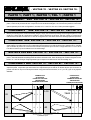 4
4
-
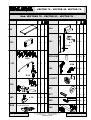 5
5
-
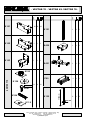 6
6
-
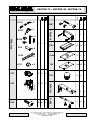 7
7
-
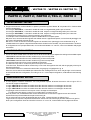 8
8
-
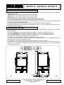 9
9
-
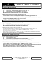 10
10
-
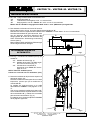 11
11
-
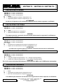 12
12
-
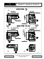 13
13
-
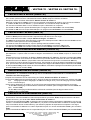 14
14
-
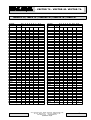 15
15
-
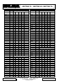 16
16
-
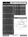 17
17
-
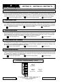 18
18
-
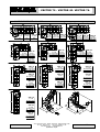 19
19
-
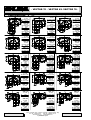 20
20
-
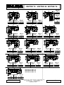 21
21
-
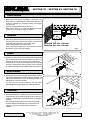 22
22
-
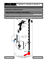 23
23
-
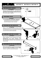 24
24
-
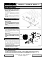 25
25
-
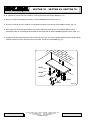 26
26
-
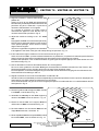 27
27
-
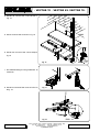 28
28
-
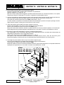 29
29
-
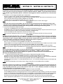 30
30
-
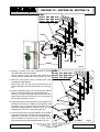 31
31
-
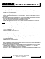 32
32
-
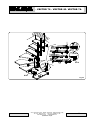 33
33
-
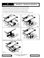 34
34
-
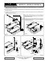 35
35
-
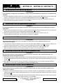 36
36
-
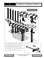 37
37
-
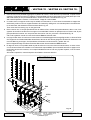 38
38
-
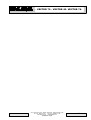 39
39
-
 40
40
-
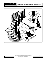 41
41
-
 42
42
-
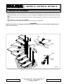 43
43
-
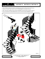 44
44
-
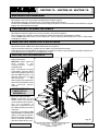 45
45
-
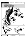 46
46
-
 47
47
-
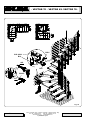 48
48


EHLEVA VECTOR 706 Assembly Instructions Manual
- Tipo
- Assembly Instructions Manual
en otros idiomas
- français: EHLEVA VECTOR 706
- italiano: EHLEVA VECTOR 706
- English: EHLEVA VECTOR 706
- Deutsch: EHLEVA VECTOR 706
Otros documentos
-
Miele 28236055USA Guía de instalación
-
Everbilt 15547 Instrucciones de operación
-
Dolle 68540 Guía de instalación
-
-
Zamma 016143948 Especificación
-
-
Zamma 017074564 Guía de instalación
-
-
-
Regalo 1235 DS Instrucciones de operación