Honeywell 6067 Manual de usuario
- Categoría
- Generadores de poder
- Tipo
- Manual de usuario
Este manual también es adecuado para

www.honeywellgenerators.com or 1-855-GEN-INFO
1400 Watt
Inverter Generator Operator's Manual
DEADLY EXHAUST FUMES! ONLY use OUTSIDE
far away from windows, doors and vents.
NOT for use in critical life support applications.
SAVE this Manual. Provide this manual to any
operator of the generator.

Accessory Box ..............................................Inside Front Cover
Introduction ..............................................................................1
Read this Manual Thoroughly ..................................................1
Safety Rules ............................................................................1
Standards Index ...............................................................3
General Information .................................................................4
Specifications ...........................................................................4
Emissions Information ......................................................4
Unit Identification ......................................................................4
Control Panel....................................................................5
Operation .................................................................................5
Pre-Use Check ..........................................................................5
Starting the Generator ...............................................................6
Adding Loads ............................................................................6
Using the EcoMode Switch .......................................................7
Using the 12 VDC Battery Charger ............................................7
Shutting Down ..........................................................................8
Low Oil Level Shutdown ............................................................8
Fueling the Generator ................................................................8
To Fill the Fuel Tank ..........................................................8
Adding Engine Oil ......................................................................9
To Add Engine Oil to the Crankcase ..................................9
Maintenance ............................................................................9
Generator Maintenance .............................................................9
Generator Maintenance Schedule ............................................10
Cleaning the Generator ............................................................10
Engine Maintenance ................................................................10
Changing the Engine Oil ..........................................................10
Changing the Fuel Filter ...........................................................11
Changing the Spark Plug .........................................................11
Transportation and Storage .....................................................11
Clean Spark Arrestor Screen ...................................................12
Troubleshooting .....................................................................13
Troubleshooting Guide .............................................................13
Notes .....................................................................................14
Warranty ................................................................................16
ACCESSORY BOX
Check all contents. If any parts are missing or damaged locate an
authorized dealer at 1-855-GEN-INFO.
Contents include:
• 1 bottle SAE 30 Oil • Oil Funnel
• Spark Plug Wrench • Screwdriver
• Battery Charge Cable
Table of Contents

1
INTRODUCTION
This model is a compact, high performance, air-cooled, engine
driven generator designed to supply electrical power to operate
electrical loads where no utility power is available or in place of
utility due to a power outage.
READ THIS MANUAL THOROUGHLY
If any portion of this manual is not understood, contact the
nearest Authorized Dealer for starting, operating and servicing
procedures.
The operator is responsible for proper and safe use of the
equipment. We strongly recommend that the operator read this
manual and thoroughly understand all instructions before using the
equipment. We also strongly recommend instructing other users to
properly start and operate the unit. This prepares them if they need
to operate the equipment in an emergency.
The generator can operate safely, efficiently and reliably only if it
is properly located, operated and maintained. Before operating or
servicing the generator:
• Become familiar with and strictly adhere to all local, state and
national codes and regulations.
• Study all safety warnings in this manual and on the product
carefully.
• Become familiar with this manual and the unit before use.
The manufacturer cannot anticipate every possible circumstance
that might involve a hazard. The warnings in this manual, and on
tags and decals affixed to the unit are, therefore, not all inclusive.
If using a procedure, work method or operating technique that the
manufacturer does not specifically recommend, ensure that it is
safe for others. Also make sure the procedure, work method or
operating technique utilized does not render the generator unsafe.
THE INFORMATION CONTAINED HEREIN WAS BASED ON
MACHINES IN PRODUCTION AT THE TIME OF PUBLICATION.
GENERAC RESERVES THE RIGHT TO MODIFY THIS MANUAL AT
ANY TIME.
SAFETY RULES
Throughout this publication, and on tags and decals affixed to the
generator, DANGER, WARNING, CAUTION and NOTE blocks are
used to alert personnel to special instructions about a particular
operation that may be hazardous if performed incorrectly or
carelessly. Observe them carefully. Their definitions are as
follows:
INDICATES A HAZARDOUS SITUATION OR
ACTION WHICH, IF NOT AVOIDED, WILL RESULT
IN DEATH OR SERIOUS INJURY.
Indicates a hazardous situation or action which,
if not avoided, could result in death or serious
injury.
Indicates a hazardous situation or action which,
if not avoided, could result in minor or moderate
injury.
NOTE:
Notes contain additional information important to a procedure
and will be found within the regular text body of this manual.
These safety warnings cannot eliminate the hazards that they
indicate. Common sense and strict compliance with the special
instructions while performing the action or service are essential to
preventing accidents.
Four commonly used safety symbols accompany the DANGER,
WARNING and CAUTION blocks. The type of information each
indicates is as follows:
This symbol points out important safety
information that, if not followed, could
endanger personal safety and/or property of
others.
This symbol points out potential explosion
hazard.
This symbol points out potential fire hazard.
This symbol points out potential electrical
shock hazard.
GENERAL HAZARDS
• NEVER operate in an enclosed area, in a vehicle, or indoors
EVEN IF doors and windows are open.
• For safety reasons, the manufacturer recommends that the
maintenance of this equipment is carried out by an Authorized
Dealer. Inspect the generator regularly, and contact the nearest
Authorized Dealer for parts needing repair or replacement.
• Operate generator only on level surfaces and where it will not be
exposed to excessive moisture, dirt, dust or corrosive vapors.
• Keep hands, feet, clothing, etc., away from drive belts, fans,
and other moving parts. Never remove any fan guard or shield
while the unit is operating.
• Certain parts of the generator get extremely hot during
operation. Keep clear of the generator until it has cooled to
avoid severe burns.
• DO NOT operate generator in the rain.
• DO NOT alter the construction of the generator or change
controls which might create an unsafe operating condition.
• Never start or stop the unit with electrical loads connected
to receptacles AND with connected devices turned ON. Start
the engine and let it stabilize before connecting electrical
loads. Disconnect all electrical loads before shutting down the
generator.
Safety Rules

2
• When working on this equipment, remain alert at all times.
Never work on the equipment when physically or mentally
fatigued.
• Never use the generator or any of its parts as a step. Stepping
on the unit can stress and break parts, and may result in
dangerous operating conditions from leaking exhaust gases,
fuel leakage, oil leakage, etc.
EXHAUST & LOCATION HAZARDS
• NEVER operate in an enclosed area, in a vehicle, or indoors!
NEVER use in the home, or in partly enclosed areas such as
garages, EVEN IF doors and windows are open! ONLY use
outdoors and far from open windows, doors, vents, and in an
area that will not accumulate deadly exhaust.
• The engine exhaust fumes contain carbon monoxide, which
you cannot see or smell. This poisonous gas, if breathed in
sufficient concentrations, can cause unconsciousness or even
death.
• Adequate, unobstructed flow of cooling and ventilating air
is critical to correct generator operation. Do not alter the
installation or permit even partial blockage of ventilation
provisions, as this can seriously affect safe operation of the
generator. The generator MUST be operated outdoors.
• This exhaust system must be properly maintained. Do nothing
that might render the exhaust system unsafe or in noncompliance
with any local codes and/or standards.
• Always use a battery operated carbon monoxide alarm indoors,
installed according to the manufacturers instructions.
• If you start to feel sick, dizzy, or weak after the generator has
been running, move to fresh air IMMEDIATELY. See a doctor, as
you could have carbon monoxide poisoning.
ELECTRICAL HAZARDS
• The generator produces dangerously high voltage when in
operation. Avoid contact with bare wires, terminals, connections,
etc., while the unit is running, even on equipment connected
to the generator. Ensure all appropriate covers, guards and
barriers are in place before operating the generator.
• Never handle any kind of electrical cord or device while
standing in water, while barefoot or while hands or feet are wet.
DANGEROUS ELECTRICAL SHOCK MAY RESULT.
• The National Electric Code (NEC) requires the frame and external
electrically conductive parts of the generator be properly
connected to an approved earth ground. Local electrical codes
may also require proper grounding of the generator. Consult
with a local electrician for grounding requirements in the area.
• Use a ground fault circuit interrupter in any damp or highly
conductive area (such as metal decking or steel work).
• Do not use worn, bare, frayed or otherwise damaged electrical
cord sets with the generator.
• In case of accident caused by electric shock, immediately shut
down the source of electrical power. If this is not possible,
attempt to free the victim from the live conductor. AVOID
DIRECT CONTACT WITH THE VICTIM. Use a non-conducting
implement, such as a rope or board, to free the victim from the
live conductor. If the victim is unconscious, apply first aid and
get immediate medical help.
FIRE HAZARDS
• Gasoline is highly FLAMMABLE and its vapors are EXPLOSIVE.
Do not permit smoking, open flames, sparks or heat in the
vicinity while handling gasoline.
• Never add fuel while unit is running or hot. Allow engine to
cool completely before adding fuel.
• Never fill fuel tank indoors. Comply with all laws regulating
storage and handling of gasoline.
• Do not overfill the fuel tank. Always allow room for fuel
expansion. If tank is over-filled, fuel can overflow onto a hot
engine and cause FIRE or an EXPLOSION. Never store generator
with fuel in tank where gasoline vapors might reach an open
flame, spark or pilot light (as on a furnace, water heater or
clothes dryer). FIRE or EXPLOSION may result. Allow unit to
cool entirely before storage.
• Wipe up any fuel or oil spills immediately. Ensure that no
combustible materials are left on or near the generator. Keep the
area surrounding the generator clean and free from debris and
keep a clearance of five (5) feet on all side to allow for proper
ventilation of the generator.
• Do not insert objects through unit’s cooling slots.
SAVE THESE INSTRUCTIONS – The manufacturer suggests that these rules for safe operation be copied and posted near the unit's
installation site. Safety should be stressed to all operators and potential operators of this equipment.
Safety Rules

3
• Do not operate the generator if connected electrical devices
overheat, if electrical output is lost, if engine or generator sparks
or if flames or smoke are observed while unit is running.
• Keep a fire extinguisher near the generator at all times.
STANDARDS INDEX
1. National Fire Protection Association (NFPA) 70: The NATIONAL
ELECTRIC CODE (NEC) available from www.nfpa.org
2. National Fire Protection Association (NFPA) 5000: BUILDING
CONSTRUCTION AND SAFETY CODE available from www.
nfpa.org
3. International Building Code available from www.iccsafe.org
4. Agricultural Wiring Handbook available from www.rerc.org ,
Rural Electricity Resource Council P.O. Box 309 Wilmington,
OH 45177-0309
5. ASAE EP-364.2 Installation and Maintenance of Farm Standby
Electric Power available from www.asabe.org, American
Society of Agricultural & Biological Engineers 2950 Niles
Road, St. Joseph, MI 49085
This list is not all inclusive. Check with the Authority Having Local
Jurisdiction (AHJ) for any local codes or standards which may be
applicable to your jurisdiction.
MODEL NO:
SERIAL NO:
Figure 1 - Generator ID Plate
ID PLATE
CALIFORNIA PROPOSITION 65 WARNING
Engine exhaust and some of its constituents are known
to the State of California to cause cancer, birth defects
and other reproductive harm.
CALIFORNIA PROPOSITION 65 WARNING
This product contains or emits chemicals known to the
State of California to cause cancer, birth defects and
other reproductive harm.
Safety Rules

4
SPECIFICATIONS
Engine Type . . . . . . . . . . . . . . . . . . . . . . . . Single Cylinder, 4-Stroke
Engine Size . . . . . . . . . . . . . . . . . . . . . . . . . . . . . . . . . . . . . . . 80cc
Starter Type . . . . . . . . . . . . . . . . . . . . . . . . . . . . . . . . . . . . . . Recoil
Fuel Capacity/Type . . . . . . . . . . . . . . . . . 0.73 Gal (2.77 L)/Unleaded
Oil Capacity . . . . . . . . . . . . . . . . . . . . . . . . . . . . . . . . 0.63 Qt (0.6L)
Runtime Full/Half Load . . . . . . . . . . . . . . . . . . . . . . . . 2.5/5.0 Hours
Spark Plug Type. . . . . . . . . . . . . . . . . . . . . . . . . . . . . . . . . BPR7HS
Spark Plug Gap . . . . . . . . . . . . . . . . . . . . . . . . . . . . . . . . . . . ..030”
Dimensions L x W x H (in) . . . . . . . . . . . . . . . . . . . . . . 22 x 12 x 18
Weight Lb/kg . . . . . . . . . . . . . . . . . . . . . . . . . . . . . . . . . 46.0/20.09
Maximum AC Output . . . . . . . . . . . . . . . . . . . . . . . . . . . . . . 1400W
Surge AC Output . . . . . . . . . . . . . . . . . . . . . . . . . . . . . . . . . 1450W
AC Volts. . . . . . . . . . . . . . . . . . . . . . . . . . . . . . . . . . . . . . . 120 VAC
Rated AC Current . . . . . . . . . . . . . . . . . . . . . . . . . . . . . . . . . .11.6 A
Frequency . . . . . . . . . . . . . . . . . . . . . . . . . . . . . . . . . . . . . . . 60 Hz
THD. . . . . . . . . . . . . . . . . . . . . . . . . . . . . . . . . . . . . . . . . . . . . 3.0%
Insulation Class . . . . . . . . . . . . . . . . . . . . . . . . . . . . . . . . . . Class B
Outlets. . . . . . . . . . . . . . . . . . . . . . . . . . . . . .(2) 5-15R, (1) 12 VDC
DC Volts. . . . . . . . . . . . . . . . . . . . . . . . . . . . . . . . . . . . . . . . 12 VDC
Rated DC Current. . . . . . . . . . . . . . . . . . . . . . . . . . . . . . . . . . . . 5 A
NOTE:
Power output and runtime are influenced by many factors,
some of which are fuel quality, ambient temperature and engine
condition. Output decreases approximately 3.5% for each 1,000
feet above sea level and 1% for every 10 degrees above 60°F.
EMISSIONS INFORMATION
The Environmental Protection Agency (EPA) and California Air
Resource Board (CARB) require that this generator comply with
exhaust and evaporative emission standards. This generator is
certified to meet the applicable EPA and CARB emission levels.
Additional information regarding the requirements set by EPA and
CARB is as follows:
It is important to follow the maintenance specifications provided in
this manual to ensure that this engine complies with the applicable
emission standards for the duration of the engine’s life. This engine
is certified to operate on gasoline. The emission control system on
the generator consists of the following:
• Fuel System • Air Induction System
~ Fuel Tank ~ Intake pipe/manifold
~ Fuel Cap ~ Air cleaner
~ Carburetor • Ignition System
~ Fuel Lines ~ Spark plug
• Exhaust System ~ Ignition module
~ Muffler
The Emissions Compliance Period referred to on the Emissions
Compliance Label indicates the number of operating hours for
which the engine has been shown to meet Federal and California
emission requirements.
UNIT IDENTIFICATION (Figure 2)
1. Carrying Handle: Lift the generator by this handle only.
2. Spark Plug Cover: Allows access to the engine spark plug.
3. Fuel System Primer: Used to prime the fuel system for
starting.
4. Fuel Cap Pressure Valve: Allows air to enter the fuel tank to
equalize pressure.
5. Fuel Tank Cap: Access to fuel tank for filling.
6. Control Panel: location of generator controls and output
receptacles.
7. Air Intake Slats: Allows for cooling air to enter the housing.
8. Muffler: Lowers engine exhaust noise (includes spark
arrestor).
9. Choke: Cold engine starting aid
10. Left Side Service Cover: Allows access to air filter, fuel filter
and oil fill.
11. Vent Hoses: Hoses allow venting of the carburetor.
12. Fuel Shutoff: Controls fuel supply to the carburetor.
13. Starter Rope: Pull rope for starting engine.
Figure 2 - Unit Identification
1
2
3
4
5
6
7
8
9
10
11
12
13
General Information

5
CONTROL PANEL (Figure 3)
14. LOW OIL LEVEL LED (yellow): Lights up when oil level is
below safe operating level and the engine shuts down..
15. OVERLOAD LED (red): Lights up if the generator experiences
a load greater than the rated output, low voltage, overheats or
the powered circuit experiences a short. The output is stopped
even though the engine keeps running.
16. READY LED (green): Indicates output from the generator
unless there is a low oil or overload condition.
17. 12 VDC Plug: Connection for re-charging 12VDC automotive-
style batteries while generator is in operation.
18. EcoMode Switch: This switch slows the engine speed when
the load is reduced to save fuel and engine wear.
19. 12 VDC Circuit Breaker: Overload protection for the 12 VDC
charging system.
20. Ground (Earth) Connection Lug: Grounding point for the
generator; consult state and local electrical codes before use
(floating ground).
21. 120 VAC Receptacles: Two (2) receptacles for connecting
electrical devices.
NOTE:
Do not exceed the rated output of the generator.
Figure 3 - 1,400 Watt Control Panel
14
15
16
17
18
19
20
21
PRE-USE CHECK
Prior to starting the generator and adding loads, perform the
following tasks:
1. Make sure the generator is on a firm, level (not to exceed 15°
in any direction), non-combustible surface with at least five
(5) feet of clearance on all sides.
NEVER operate in an enclosed area, in a
vehicle, or indoors! NEVER use in the home,
or in partly enclosed areas such as garages,
EVEN IF doors and windows are open! ONLY
use outdoors and far from open windows,
doors, vents, and in an area that will not
accumulate deadly exhaust.
The engine exhaust fumes contain carbon
monoxide, which you cannot see or smell.
This poisonous gas, if breathed in sufficient
concentrations, can cause unconsciousness
or even death.
Adequate, unobstructed flow of cooling and
ventilating air is critical to correct generator
operation. Do not alter the installation or
permit even partial blockage of ventilation
provisions, as this can seriously affect safe
operation of the generator. The generator
MUST be operated outdoors.
This exhaust system must be properly
maintained. Do nothing that might render the
exhaust system unsafe or in noncompliance
with any local codes and/or standards.
The manufacturer recommends installing
a battery operated carbon monoxide alarm
indoors, according to the manufacturers
instructions.
NEVER use in the home, or in partly enclosed
areas such as garages, vehicles, campers
or trailers. ONLY use outdoors and far from
open windows, doors, vents.
2. Remove the fuel cap and check the fuel level. If fuel is needed,
see the section “FUELING THE GENERATOR”.
Operation

6
3. Remove the left side service cover and check the oil level
by removing the oil filler cap. The oil level should be to the
bottom of the threads on the oil fill pipe. If oil is needed, see
the section “ADDING ENGINE OIL”.
4. Replace and secure the left side service cover.
5. Make sure there are no electrical devices connected to the
generator.
6. The National Electric Code (NEC) requires the frame and
external electrically conductive parts of the generator be
properly connected to an approved earth ground. Proper
grounding of the generator will prevent electrical shock in
the event of a ground fault condition in the generator or in
connected electrical devices. Proper grounding also helps
dissipate static electricity, which often builds up in unguarded
devices.
7. Local electrical codes may also require proper grounding of
the generator.
Starting the generator with accessories
connected to the 120 VAC outlets will
damage the generator and the connected
accessories.
STARTING THE GENERATOR
Once the fuel and oil levels have been checked and it has been
verified there are no electrical devices connected, the generator
may be started. Turn the EcoMode Switch OFF (O).
1. Open the fuel valve (Figure 4), located below the starter rope
pull, by turning to the valve 90° counter-clockwise to the “ON”
(I) position.
2. Pull up on the center of the fuel fill cap and prime the fuel
system by depressing the plunger up to five (5) times with the
vent closed (OFF) (Figure 5).
3. Open the fuel tank vent on the top of the fuel fill cap by turning
the center portion to the “ON” mark (Figure 5).
4. If the engine is cold or has not been run for some time, engage
the choke by pushing the choke lever to the right (Figure 6).
5. Grip the handle for the pull starter and brace your other hand
against the generator. Pull the rope slowly until resistance is
felt, then pull the rope rapidly.
6. If the engine does not start, repeat steps 2-5 until the engine
fires and begins to run.
Figure 4 - Fuel Valve
TURNING THE FUEL ON
7. Carefully adjust the choke to approximately the ½ position
until the engine begins to run smoothly, then push the lever all
the way to the left (Figure 6).
8. Make sure the bottom of the generator is not blocked by sand,
leaves, grass, etc. as the cooling vents are located on the
bottom of the unit.
Figure 5 - Prime Fuel System
FUEL
SYSTEM
VENT
PLUNGER
VENT
Figure 6 - Adjust Choke
ENGINE CHOKE
OPERATION
ON
I
OFF
O
ADDING LOADS
Once the generator has been running smoothly for 2-3 minutes,
electrical devices can be plugged in.
Do not use worn, bare, frayed or otherwise
damaged electrical cord sets with the
generator. Do not handle any kind of
electrical device while standing in water,
while barefoot, or while hands or feet are
wet.
1. There are two grounded 120 VAC duplex outlets on the front
of the generator.
2. DO NOT overload the generator; if the red “overload” LED lights
up and the devices attached to the generator stop operating,
stop the engine and reduce the load to the generator. Restart
and apply reduced loads.
Operation

7
3. Consult the following table to estimate what can be powered
by the generator.
Device . . . . . . . . . . . . . . . . . . . . . . . . . . . . . . . .Running Watts
*Air Conditioner (12,000 Btu) . . . . . . . . . . . . . . . . . . . . . . . . .1700
Battery Charger (20 Amp) . . . . . . . . . . . . . . . . . . . . . . . . . . . . . 500
Belt Sander (3") . . . . . . . . . . . . . . . . . . . . . . . . . . . . . . . . . . . . 1000
Chain Saw . . . . . . . . . . . . . . . . . . . . . . . . . . . . . . . . . . . . . . . . 1200
Circular Saw (6-1/2"). . . . . . . . . . . . . . . . . . . . . . . . . . 800 to 1000
*Clothes Dryer (Gas) . . . . . . . . . . . . . . . . . . . . . . . . . . . . . . . . . 700
*Clothes Washer . . . . . . . . . . . . . . . . . . . . . . . . . . . . . . . . . . . 1150
Coffee Maker . . . . . . . . . . . . . . . . . . . . . . . . . . . . . . . . . . . . . . 1750
*Compressor (3/4 HP). . . . . . . . . . . . . . . . . . . . . . . . . . . . . . . 1800
*Compressor (1/2 HP). . . . . . . . . . . . . . . . . . . . . . . . . . . . . . . 1400
Curling Iron . . . . . . . . . . . . . . . . . . . . . . . . . . . . . . . . . . . . . . . . 700
*Dehumidifier . . . . . . . . . . . . . . . . . . . . . . . . . . . . . . . . . . . . . . 650
Disc Sander (9") . . . . . . . . . . . . . . . . . . . . . . . . . . . . . . . . . . . 1200
Edge Trimmer . . . . . . . . . . . . . . . . . . . . . . . . . . . . . . . . . . . . . . 500
Electric Blanket . . . . . . . . . . . . . . . . . . . . . . . . . . . . . . . . . . . . . 400
Electric Nail Gun. . . . . . . . . . . . . . . . . . . . . . . . . . . . . . . . . . . . 1200
Electric Range (per element) . . . . . . . . . . . . . . . . . . . . . . . . . . 1500
Electric Skillet . . . . . . . . . . . . . . . . . . . . . . . . . . . . . . . . . . . . . 1250
*Freezer. . . . . . . . . . . . . . . . . . . . . . . . . . . . . . . . . . . . . . . . . . . 700
*Furnace Fan (3/5 HP). . . . . . . . . . . . . . . . . . . . . . . . . . . . . . . . 875
*Garage Door Opener. . . . . . . . . . . . . . . . . . . . . . . . . . . 500 to 750
Hair Dryer . . . . . . . . . . . . . . . . . . . . . . . . . . . . . . . . . . . . . . . . 1200
Hand Drill. . . . . . . . . . . . . . . . . . . . . . . . . . . . . . . . . . . 250 to 1100
Hedge Trimmer . . . . . . . . . . . . . . . . . . . . . . . . . . . . . . . . . . . . . 450
Impact Wrench . . . . . . . . . . . . . . . . . . . . . . . . . . . . . . . . . . . . . 500
Iron . . . . . . . . . . . . . . . . . . . . . . . . . . . . . . . . . . . . . . . . . . . . . 1200
*Jet Pump . . . . . . . . . . . . . . . . . . . . . . . . . . . . . . . . . . . . . . . . . 800
Lawn Mower . . . . . . . . . . . . . . . . . . . . . . . . . . . . . . . . . . . . . . 1200
Light Bulb . . . . . . . . . . . . . . . . . . . . . . . . . . . . . . . . . . . . . . . . . 100
Microwave Oven . . . . . . . . . . . . . . . . . . . . . . . . . . . . . 700 to 1000
*Milk Cooler . . . . . . . . . . . . . . . . . . . . . . . . . . . . . . . . . . . . . .1100
Oil Burner on Furnace. . . . . . . . . . . . . . . . . . . . . . . . . . . . . . . . . 300
Oil Fired Space Heater (140,000 Btu) . . . . . . . . . . . . . . . . . . . . . 400
Oil Fired Space Heater (85,000 Btu) . . . . . . . . . . . . . . . . . . . . . . 225
Oil Fired Space Heater (30,000 Btu) . . . . . . . . . . . . . . . . . . . . . . 150
*Paint Sprayer, Airless (1/3 HP) . . . . . . . . . . . . . . . . . . . . . . . . . 600
Paint Sprayer, Airless (handheld) . . . . . . . . . . . . . . . . . . . . . . . . 150
Radio. . . . . . . . . . . . . . . . . . . . . . . . . . . . . . . . . . . . . . . . 50 to 200
*Refrigerator . . . . . . . . . . . . . . . . . . . . . . . . . . . . . . . . . . . . . . . 700
Slow Cooker . . . . . . . . . . . . . . . . . . . . . . . . . . . . . . . . . . . . . . . 200
*Submersible Pump (1/2 HP). . . . . . . . . . . . . . . . . . . . . . . . . . 1500
*Sump Pump. . . . . . . . . . . . . . . . . . . . . . . . . . . . . . . . 800 to 1050
* Allow three (3) times the listed running watts for starting theses devices.
NOTE:
When an electric motor is started, the "OVERLOAD" LED may
light up for up to five (5) seconds (this is normal). If it stays on,
a fault has occured. Unplug all devices and shut down generator
to reset the alarm. Restart the generator. If the "OVERLOAD"
LED remains lit, contact a Dealer for assistance.
USING THE ECOMODE SWITCH
When the electrical devices connected to the generator are going
to be used intermittently (such as a hand drill), the EcoMode
switch can be pushed to the “ON” (I) position. This will lower the
generator engine speed when loads are not being applied, saving
fuel, reducing engine wear, noise, and extending runtime.
USING THE 12 VDC BATTERY
CHARGER
The 12 VDC receptacle (1600 & 2000 only) may be used to
recharge 12 VDC automotive type batteries only. The DC charging
output is not regulated. The circuit protector does not prevent over-
charging a battery.
1. Connect the charging cable to the generator first, then the
battery, ALWAYS connecting the red lead to positive (+) and
the black to negative (-).
DO NOT permit smoking, open flame,
sparks or any other source of heat around
a battery. Wear protective goggles, rubber
apron and rubber gloves when working
around a battery. Battery electrolyte fluid is
an extremely corrosive sulfuric acid solution
that can cause severe burns. If a spill occurs,
flush area with clear water immediately.
Storage batteries give off explosive hydrogen
gas while recharging. An explosive mixture
will remain around the battery for a long
time after it has been charged. The slightest
spark can ignite the hydrogen and cause an
explosion. Such an explosion can shatter the
battery and cause blindness or other serious
injury.
NEVER reverse the polarity when connecting
the battery terminals to the charging jack.
Severe damage may occur to the generator
and battery.
2. Keep the EcoMode switch in the “OFF” (O) position.
3. Start the generator and use it as normal. Charging time will
vary with battery size and condition. Check the voltage with a
multi-meter at the battery terminals once the charging cable
has been unplugged, or the generator has been shut down.
NOTE:
This receptacle can not recharge 6-Volt batteries
and can not be used to crank an engine having a
discharged battery.
Operation

8
SHUTTING DOWN
Once the generator is no longer needed it can be shut down.
1. Switch off any electrical devices connected to the generator.
Unplug any cords to the 120 VAC duplex outlets or the 12 VDC
plug.
2. Turn the fuel valve to the “OFF” (O) position (Figure 7). A
switch behind the fuel valve grounds the ignition system,
stopping the engine and the fuel supply is shut off.
3. Close the vent on the fuel cap.
4. Allow the generator to cool before moving or storing.
Always allow the generator to cool off before
storing. High temperatures will be present
at the rear of the unit for some time after
shutdown.
Figure 7 - Turn Off Fuel
TURNING THE FUEL OFF
LOW OIL LEVEL SHUTDOWN
This generator is equipped with a low oil level shut down. If the oil
level in the engine crankcase drops below a pre-determined level,
the engine will stop automatically and the “LOW OIL LEVEL” LED
will light up.
Remove the Left Side Service Cover and check the oil level of
the engine. Add or drain oil as necessary; refer to see the section
“ADDING ENGINE OIL”.
FUELING THE GENERATOR
Use care when fueling the generator. Only fill the fuel tank when
the generator has cooled entirely. Use fresh unleaded gasoline with
a minimum Research Octane Number (RON) of 87.
NOTE:
Do not use any gasoline containing more than 10% Ethanol.
NEVER fill the fuel tank with E85 or a mixture of oil and gasoline
designated for two-cycle engines.
DO NOT light a cigarette or smoke when
filling the fuel tank.
Gasoline is highly FLAMMABLE and its
vapors are EXPLOSIVE. DO NOT permit
smoking, open flames, sparks or heat in the
vicinity while handling gasoline.
NEVER fill fuel tank indoors. NEVER fill fuel
thank when engine is running or hot. Avoid
spilling gasoline on a hot engine. Allow
engine to cool entirely before filling fuel tank.
DO NOT overfill the fuel tank. ALWAYS allow
room for fuel expansion. If tank is over-filled,
fuel can overflow onto a hot engine and
cause FIRE or an EXPLOSION. Wipe up fuel
spills immediately!
TO FILL THE FUEL TANK
1. Remove the fuel tank cap.
2. Add fuel slowly, stopping about two (2) inches below the top
of the filler neck.
3. Replace the fuel tank cap. Make sure the valve on the fuel cap
is in the “OFF” position.
4. If the generator is going to be started, refer to the section
“STARTING THE GENERATOR” for additional directions on
priming the fuel system.
Figure 8 - Fuel Tank Cap
FUEL
TANK
CAP
FILL TANK UNTIL
FUEL IS TWO (2)
INCHES BELOW
THE TOP
Operation

9
ADDING ENGINE OIL
All oil should meet minimum American Petroleum Institute (API)
Service Class SJ, SL or better. Do not use any aftermarket
additives.
Select the oil's viscosity grade according to the expected operating
temperature.
• Above 40° F, use SAE 30
• Below 40° F to 10° F, use 10W-30
• Below 10° F, use synthetic 5W-30
10W-30
10W -3 0
SAE 30
SAE 3 0
Synthetic 5W-30
Syn t het i c 5W -3 0
TO ADD ENGINE OIL TO THE CRANKCASE
1. Place the unit on a firm, level surface (not to exceed 15° in any
direction).
2. Remove the Left Side Service Cover.
3. Remove the oil fill cap located on the bottom of the engine
crankcase.
4. Add the recommended engine oil slowly, stopping frequently
to check the level. The full level is the base of the threads in
the filler neck. DO NOT OVERFILL!
5. Replace the oil fill cap and tighten.
6. Always check the oil level before starting the generator
engine.
DO NOT overfill the engine crankcase with
oil. High oil pressure may result, causing
premature engine wear and damage.
Figure 9 - Oil Fill
FULL OIL LEVEL
IS THE BOTTOM
OF THESE
THREADS
OIL FILL
CAP
GENERATOR MAINTENANCE
Proper care will ensure maximum performance of your generator.
Generator maintenance consists of keeping the unit clean and dry.
Operate and store the unit in a clean dry environment where it will
not be exposed to excessive dust, dirt, moisture or any corrosive
vapors.
Cooling air slots in the generator must not become clogged with
snow, leaves, or any other foreign material.
Check the cleanliness of the generator frequently and clean when
dust, dirt, oil, moisture or other foreign substances are visible on
its exterior surface.
NOTE:
Never insert any object or tool through the air cooling slots,
even if the engine is not running.
NOTE:
DO NOT use a garden hose to clean the generator. Water
can enter the engine fuel system and cause problems. In
addition, if water enters the generator through cooling air
slots, some water will be retained in voids and crevices of the
rotor and stator winding insulation. Water and dirt buildup on
the generator internal windings will eventually decrease the
insulation resistance of these windings.
Maintenance

10
GENERATOR MAINTENANCE
SCHEDULE
Follow the recommended service schedule; to order replacement
parts call 1-855-436-4636.
Each
Use
Every 100
Hours
Every 6
Months
Each
Year
Fuel Level X
Oil Level X
Check Air Filter X
*Change Engine Oil X
**Clean Air Filter X
Check Spark Plug X
Check Muffler X
Replace Spark Plug X
Replace Fuel Filter X
* Perform initial oil change after the first five (5) hours of operation
** Clean the air filter more often if operating in dusty or sandy
conditions. Replace as necessary.
CLEANING THE GENERATOR
1. Use a damp cloth to wipe exterior surfaces clean.
2. A soft, bristle brush may be used to loosen caked on dirt, oil,
etc.
3. A vacuum cleaner may be used to pick up loose dirt and
debris.
4. Low pressure air (not to exceed 25 psi) may be used to
blow away dirt. Inspect cooling air slots and openings
on the generator. These openings must be kept clean and
unobstructed.
5. Inspect the vent hoses on the left side of the generator. Make
sure the hoses protrude through the slots below the door and
that the ends are open and free of debris.
ENGINE MAINTENANCE
NOTE:
Only work on a generator that has cooled completely.
Inspect the oil level and air filter condition each time you are going
to use the generator. To check the air filter and oil level the left side
service cover must be removed; use a screwdriver to loosen the
screw securing the cover and remove.
The air filter is located behind a cover for the air box (Figure 10).
Push the tab on the bottom of the air box upwards to release the
cover. To service the air cleaner:
1. Remove the air cleaner. Tap the element to shake loose any
large particles.
2. Wash the element in soapy water. Squeeze the filter dry in
clean cloth (DO NOT TWIST).
3. Soak the filter element in clean engine oil. Squeeze the excess
oil from the filter, leaving a light coating.
4. Clean air cleaner housing and cover before re-installing the
filter element.
5. To order a new air filter, you will need part number 0H63620134.
Figure 10 - Air Filter
AIR
FILTER
FILTER
HOUSING
COVER
LEFT SIDE
SERVICE COVER
SCREW
LEFT SIDE
SERVICE
COVER
CHANGING THE ENGINE OIL
Hot oil may cause burns. Allow engine
to cool entirely before draining oil. Avoid
prolonged or repeated skin exposure with
used oil. Thoroughly wash exposed areas
with soap.
Change the engine oil after the first five (5) hours of operation.
Change the engine oil every 100 hours thereafter. To change the
engine oil:
Change the oil only when the fuel tank is low
or nearly empty. Tipping the generator with a
full fuel tank may cause fuel leakage.
1. Place the generator over a drain pan and remove the drain
plug. Tip the generator on its side to drain the used oil from
the crankcase.
NOTE:
To make draining the oil easier, a 6” length of vinyl (PVC) hose
with an inside diameter of 1.25” (32mm) may be placed over
the drain lip.
2. Tip the generator upright once the oil has finished draining.
Replace the engine oil with the proper grade called out in
Section “ADDING ENGINE OIL”, then replace the drain plug.
Maintenance

11
CHANGING THE FUEL FILTER
Locate the fuel filter, just below the engine intake housing (Figure
11). Make sure the Fuel Shutoff is in the “OFF” (O) position.
1. Remove the pinch clamps securing the fuel filter. Pull the
hoses free.
Wipe up any fuel spills immediately! Do not
smoke or replace the fuel filter near sparks
or open flame!
2. Replace the used filter with a new one (Part Number
0H43470180). Push the fuel hoses onto the barbed filter
fittings until they are seated completely.
3. Replace the clamps, making sure they are seated on the
fittings.
Figure 11 - Fuel Filter
FUEL
FILTER
OIL FILL PLUG/
OIL DRAIN
CRANKCASE
VENT HOSE
CARBURETOR
VENT HOSE
CHANGING THE SPARK PLUG
Replace the spark plug each year, regardless of how many hours
the generator has been run. Use the spark plug identified in the
"SPECIFICATIONS" section for each generator size. The spark plug
gap should be .030” (.76mm). To replace the spark plug:
1. Remove the spark plug cover on the top right side of the
generator, just below the handle (Figure 12).
2. Carefully pull the spark plug lead from the spark plug. Use a
socket wrench to remove the spark plug.
3. Install the new spark plug into the cylinder head. Tighten the
spark plug to 15 ft/lb.
4. Replace the spark plug lead, making sure it is fully seated.
5. Replace the spark plug cover.
Figure 12 - Replace Spark Plug
SPARK PLUG
LOCATION
TRANSPORTATION AND STORAGE
Transport or store the generator only if it has cooled completely.
Make sure the fuel valve and the vent on the fuel cap are both in
the OFF (“O”) position.
It is important to prevent gum deposits from forming in essential
fuel system parts such as the carburetor, fuel hose or tank during
long-term storage. Also, experience indicates that alcohol-blended
fuels (called gasohol, ethanol or methanol) can attract moisture,
which leads to separation and formation of acids; these acids in
gas can damage the fuel system of an engine while in storage.
To avoid engine problems, the use of a commercial fuel stabilizer
prior to storage is recommended. Follow the manufacturer’s
instructions when adding the fuel stabilizer.
If the generator is going to be stored for more than six (6) months,
the generator should be prepared as follows:
1. Remove all gasoline from the fuel tank.
2. Start and run engine until engine stops from lack of fuel or
open the valve on carburetor bowl (Figure 13), and allow
gasoline to drain down tube into a receptacle. Discard
appropriately. Be sure to close the valve once the gasoline has
drained.
3. After the engine cools down, drain oil from crankcase. Refill
with recommended grade.
4. Remove spark plug and pour about 1/2 ounce (15 ml) of
engine oil into the cylinder. Cover spark plug hole with rag. Pull
the starting rope several times to coat the cylinder walls with
engine oil.
5. Install and tighten the spark plug.
6. Clean the generator outer surfaces. Check that cooling air
slots and openings on generator are open and unobstructed.
7. Store the unit in a clean, dry place.
Maintenance

12
Do not store gasoline from one season to another.
If possible, store the unit indoors and cover it to give protection
from dust and dirt.
Figure 13 - Carburetor Drain Valve
CARBUREATOR DRAIN
VALVE LOCATED BEHIND
AIR INTAKE
TURN VALVE COUNTER-
CLOCKWISE TO DRAIN FUEL,
CLOCKWISE TO CLOSE
CLEAN SPARK ARRESTOR SCREEN
The engine exhaust muffler has a spark arrestor screen. Inspect
and clean the screen every 50 hours of operation or once each
year, whichever comes first.
NOTE:
If using the generator on any forest covered, brush covered
unimproved land, it MUST BE equipped with a spark arrestor.
The spark arrestor must be maintained in cood condition by the
owner/operator.
Clean and ispect the spark arrestor as follows:
• Remove the screen retainer by removing the retainer clamp.
• Slide the spark arrestor screen out from the muvvler outlet tube.
• Inspect screen and replace if torn, perforated or otherwise
damaged. Do NOT use a defective screen. If screen is not
damaged, clean with a commercial solvent.
• Replace the screen and retainer and secure with retainer clamp.
Figure 14 - Spark Arrestor Screen
Maintenance

13
TROUBLESHOOTING GUIDE
PROBLEM CAUSE CORRECTIVE ACTION
Engine won't start. 1. No fuel in tank.
2. Fuel valve turned off.
3. Defective spark plug.
4. Plugged fuel filter.
5. Defective or stuck engine stop switch.
1. Add fuel to tank.
2. Turn fuel valve on.
3. Replace spark plug.
4. Replace fuel filter.
5. Replace engine start switch.
Engine starts, then shuts down. 1. Low fuel level.
2. Fuel tank vent closed.
3. Incorrect engine oil level.
4. Contaminated fuel.
5. Defective low oil level switch.
6. Defective ignition coil.
1. Add fuel to tank.
2. Open fuel tank vent.
3. Check engine oil level, add or drain as needed.
4. Replace fuel filter.
5. Replace Low Oil Level switch.
6. Replace ignition coil.
Engine starts, then runs rough.* 1. Choke is stuck or left on.
2. Dirty or clogged air filter.
3. Defective or dirty spark plug.
4. Dirty fuel filter.
5. Defective EcoMode switch.
1. Turn choke off.
2. Clean or replace the air filter element.
3. Replace spark plug.
4. Replace fuel filter.
5. Replace EcoMode switch.
No AC output. 1. Generator is overloaded (OVERLOAD LED is on).
2. AC voltage is low (OVERLOAD LED is on).
3. Inverter module is overheated (OVERLOAD LED is
on).
4. Short circuit in electrical device (OVERLOAD LED
is on).
5. Defective inverter assembly.
1. Shut down generator to reset module. Reduce
loads and restart generator.
2. Verify vent is open and choke is OFF.
3. Verify service door is ON. Let cool for 15 minutes
and restart generator.
4. Verify condition of any extension cords and all
items being powered.
5. Replace inverter assembly.
No DC output. ** 1. DC circuit breaker is open.
2. Defective DC circuit breaker.
3. Defective rectifier.
1. Reset DC circuit breaker.
2. Replace DC circuit breaker.
3. Replace rectifier.
Fuel leaks from drain hoses. 1. Fuel system over primed (flooded).
2. Carburetor drain in bowl is not closed.
1. Turn vent in cap ON and let generator sit 15
minutes before restarting.
2. Turn valve clockwise to close.
* Engine speed increases and decreases — This is normal as the generator starts up and as loads vary.
** Verify EcoMode Switch is in the "O" OFF position.
Troubleshooting

14
Notes

15
Notes

16
Warranty
CALIFORNIA AND U.S. EPA EMISSION CONTROL WARRANTY STATEMENT
YOUR WARRANTY RIGHTS AND OBLIGATIONS
The California Air Resource Board (CARB) and the United States Environmental Protection Agency (EPA), together with Generac Power Systems, Inc.
(Generac) are pleased to explain the Emission Control System Warranty (ECS Warranty) on your new 2012 equipment. New equipment that use small spark-
ignited engines must be designed, built, and equipped to meet stringent anti-smog standards for the state of California and the federal government. Generac
will warrant the emission control system on your equipment for the period of time listed below provided there has been no abuse, neglect, unapproved
modification or improper maintenance of your equipment.
The emission control system on this equipment includes all components whose failure would increase the emissions of any regulated pollutant. These
components are listed in the Emissions Information section of this manual.
MANUFACTURER’S WARRANTY COVERAGE:
This ECS Warranty is valid for two years, or for the same period as specified in the Generac Limited Warranty, whichever is longer. For equipment with hour
meters, the warranty period is a number of hours equal to half the Useful Life to which the equipment is certified, or the warranty period specified above in
years, whichever is less. The Useful Life can be found on the Emission Control Label on the engine. If, during such warranty period, any emission-related
part on your equipment is found to be defective in materials or workmanship, repairs or replacement will be performed by a Generac Authorized Warranty
Service Dealer.
OWNER'S WARRANTY RESPONSIBILITIES:
As the equipment owner, you are responsible for the completion of all required maintenance as listed in your factory supplied Owner's Manual. For warranty
purposes, Generac recommends that you retain all receipts covering maintenance on your generator, but Generac cannot deny warranty solely due to the
lack of receipts.
You should be aware that Generac may deny any and/or all warranty coverage or responsibility if your equipment, or a part/component thereof, has failed
due to abuse, neglect, improper maintenance, or unapproved modifications.
You are responsible for contacting a Generac Authorized Warranty Dealer as soon as a problem occurs. The warranty repairs should be completed
in a reasonable amount of time, not to exceed 30 days.
Warranty service can be arranged by contacting either your selling dealer or a Generac Authorized Warranty Service Dealer. To locate the Generac Authorized
Warranty Service Dealer nearest you, call our toll free number below, or email [email protected].
1-800-333-1322
IMPORTANT NOTE: This warranty statement explains your rights and obligations under the Emission Control System Warranty, which is provided to you
by Generac pursuant to federal law. See also the "Generac Limited Warranties for Generac Power Systems, Inc.," which is enclosed herewith on a separate
sheet, also provided to you by Generac. Note that this warranty shall not apply to any incidental, consequential or indirect damages caused by defects in
materials or workmanship or any delay in repair or replacement of the defective part(s). This warranty is in place of all other warranties, expressed or implied.
Specifically, Generac makes no other warranties as to the merchantability or fitness for a particular purpose. Any implied warranties allowed by law shall
be limited in duration to the terms of the express warranty provided herein. Some states do not allow limitations on how long an implied warranty lasts, so
the above limitation may not apply to you.
The ECS Warranty applies only to the emission control system of your new equipment. Both the ECS Warranty and the Generac Warranty describe important
rights and obligations with respect to your new engine.
Warranty service can be performed only by a Generac Authorized Warranty Service Facility. When requesting warranty service, evidence must be presented
showing the date of the sale to the original purchaser/owner.
If you have any questions regarding your warranty rights and responsibilities, you should contact Generac at the following address:
ATTENTION WARRANTY DEPARTMENT
GENERAC POWER SYSTEMS, INC.
P.O. BOX 297 • WHITEWATER, WI 53190
Part 1 of 2
Part No. 0J8147B Rev. A 01/12

17
Warranty
EMISSION CONTROL SYSTEM WARRANTY
Emission Control System Warranty (ECS Warranty) for equipment using small spark-ignited engines:
(a) Applicability: This warranty shall apply to equipment that uses small off-road engines. The ECS Warranty period shall begin on the date the new
equipment is purchased by/delivered to its original, end-use purchaser/owner and shall continue for the lesser of:
(1) The period of time specified in the Generac Limited Warranty enclosed herewith, but not less than 24 months, or
(2) For engines equipped with hour meters, a number of operating hours equal to half of the engine’s useful life. The useful life is specified on the
Emissions Control Label on the engine.
(b) General Emissions Warranty Coverage: Generac warrants to the original, end-use purchaser/owner of the new engine or equipment and to each
subsequent purchaser/owner that the ECS when installed was:
(1) Designed, built and equipped so as to conform with all applicable regulations; and
(2) Free from defects in materials and workmanship which cause the failure of a warranted part at any time during the ECS Warranty Period.
(c) The warranty on emissions-related parts will be interpreted as follows:
(1) Any warranted part that is not scheduled for replacement as required maintenance in the Owner's Manual shall be warranted for the ECS
Warranty Period. If any such part fails during the ECS Warranty Period, it shall be repaired or replaced by Generac according to Subsection (4)
below. Any such part repaired or replaced under the ECS Warranty shall be warranted for the remainder of the ECS Warranty Period.
(2) Any warranted part that is scheduled only for regular inspection as specified in the Owner's Manual shall be warranted for the ECS Warranty
Period. A statement in the Owner’s Manual to the effect of "repair or replace as necessary" shall not reduce the ECS Warranty Period. Any
such part repaired or replaced under the ECS Warranty shall be warranted for the remainder of the ECS Warranty Period.
(3) Any warranted part that is scheduled for replacement as required maintenance in the Owner's Manual shall be warranted for the period of time
prior to first scheduled replacement point for that part. If the part fails prior to the first scheduled replacement, the part shall be repaired or
replaced by Generac according to Subsection (4) below. Any such emissions-related part repaired or replaced under the ECS warranty shall be
warranted for the remainder of the period prior to the first scheduled replacement point for that part.
(4) Repair or replacement of any warranted, emissions-related part under this ECS Warranty shall be performed at no charge to the owner at a
Generac Authorized Warranty Service Facility.
(5) Notwithstanding the provisions of subsection (4) above, warranty services or repairs must be provided at Generac Authorized Service
Facilities.
(6) When the engine is inspected by a Generac Authorized Warranty Service Facility, the purchaser/owner shall not be held responsible for
diagnostic costs if the repair is deemed warrantable.
(7) Throughout the ECS Warranty Period, Generac shall maintain a supply of warranted emission-related parts sufficient to meet the expected
demand for such parts.
(8) Any Generac authorized and approved emission-related replacement parts may be used in the performance of any ECS Warranty maintenance
or repairs and will be provided without charge to the purchaser/owner. Such use shall not reduce Generac ECS Warranty obligations.
(9) No modifications, other than those explicitly approved by Generac, may be made to the generator. Unapproved modifications void this ECS
Warranty and shall be sufficient ground for disallowing an ECS Warranty claim.
(10) Generac shall not be held liable hereunder for failures of any non-authorized replacement parts, or failures of any authorized parts caused by
the use of non-authorized replacement parts.
EMISSION RELATED PARTS MAY INCLUDE THE FOLLOWING (IF EQUIPPED):
1) FUEL METERING SYSTEM
A. CARBURETOR AND INTERNAL PARTS
B. FUEL TANK / CAP
C. FUEL LINES
D. EVAPORATIVE VENT LINES
E. REGULATOR (GASEOUS FUELS)
F. CARBON CANISTER
2) AIR INDUCTION SYSTEM
A. INTAKE MANIFOLD
B. AIR FILTER
3) IGNITION SYSTEM
A. SPARK PLUGS
B. IGNITION COILS / MODULE
4) AIR INJECTION SYSTEM
A. PULSE AIR VALVE
5) EXHAUST SYSTEM
A. CATALYST
B. EXHAUST MANIFOLD
Part 2 of 2
Part No. 0J8147B Rev. A 01/12

Manual Part No. 0J5876 Revision B (02/17/12)
Warranty
GENERAC POWER SYSTEMS “TWO YEAR” LIMITED WARRANTY FOR
HONEYWELL PORTABLE INVERTER GENERATORS
For a period of two (2) years from the date of original sale, Generac Power Systems, Inc. (Generac) warrants its Honeywell portable inverter generators will be free from
defects in materials and workmanship for the items and period set forth below. Generac will, at its option, repair or replace any part which, upon examination, inspection and
testing by Generac or a Generac/Honeywell Authorized Warranty Service Dealer, is found to be defective. Any equipment that the purchaser/owner claims to be defective must
be returned to and examined by the nearest Generac/Honeywell Authorized Warranty Service Dealer. All transportation costs under the warranty, including return to the factory,
are to be borne and prepaid by the purchaser/owner. This warranty applies only to Honeywell portable inverter generators and is not transferable from original purchaser. Save
your proof-of-purchase receipt. If you do not provide proof of the initial purchase date, the manufacturer’s shipping date of the product will be used to determine the warranty
period.
** This warranty only applies to units sold for use in the U.S.A. and Canada.**
WARRANTY SCHEDULE
Consumer applications are warranted for two (2) years. Commercial and Rental applications are warranted for six (6) months.
CONSUMER APPLICATION
YEAR ONE - Limited Comprehensive coverage on Labor and Part(s) listed (proof of purchase and maintenance is required):
• Engine- All Components
• Alternator- All Components
YEAR TWO - Limited Comprehensive coverage on Part(s) listed (proof of purchase and maintenance is required):
• Engine- All Components
• Alternator- All Components
COMMERCIAL/RENTAL APPLICATION
FIRST SIX MONTHS – Limited Comprehensive coverage on Labor and Part(s) listed (proof of purchase and maintenance is required):
• Engine- All Components
• Alternator- All Components
NOTE: For the purpose of this warranty “consumer use” means personal residential household or recreational use by original purchaser. This warranty does not apply to
units used for Prime Power in place of utility where utility power service is present or where utility power service does not normally exist. Once a generator has
experienced commercial or rental use, it shall thereafter be considered a non-consumer use generator for the purpose of this warranty.
All warranty expense allowances are subject to the conditions defined in Generac’s Service Policy Manual.
THIS WARRANTY SHALL NOT APPLY TO THE FOLLOWING:
• Use of Non-Generac replacement part(s) will void the warranty in its entirety.
• Costs of normal maintenance and adjustments.
• Failures caused by any contaminated fuels, oils or lack of proper oil levels.
• Repairs or diagnostics performed by individuals other than Generac/Honeywell authorized dealers not authorized in writing by Generac.
• Failures due, but not limited, to normal wear and tear, accident, misuse, abuse, negligence or improper use. As with all mechanical devices, the Generac engines need periodic
part(s) service and replacement to perform as designed. This warranty will not cover repair when normal use has exhausted the life of a part(s) or engine.
• Failures caused by any act of God and other force majeure events beyond the manufacturer's control.
• Damage related to rodent and/or insect infestation.
• Products that are modified or altered in a manner not authorized by Generac in writing.
• Any incidental, consequential or indirect damages caused by defects in materials or workmanship, or any delay in repair or replacement of the defective part(s).
• Failure due to misapplication.
• Telephone, cellular phone, facsimile, internet access or other communication expenses.
• Living or travel expenses of person(s) performing service, except as specifically included within the terms of a specific unit warranty period.
• Expenses related to “customer instruction” or troubleshooting where no manufacturing defect is found.
• Rental equipment used while warranty repairs are being performed.
• Overnight freight or special shipping costs for replacement part(s).
• Overtime, holiday or emergency labor.
• Starting batteries, fuses, light bulbs and engine fluids.
THIS WARRANTY IS IN PLACE OF ALL OTHER WARRANTIES, EXPRESSED OR IMPLIED, SPECIFICALLY, GENERAC POWER SYSTEMS MAKES NO OTHER WARRANTIES AS TO
THE MERCHANTABILITY OR FITNESS FOR A PARTICULAR PURPOSE. Any implied warranties which are allowed by law, shall be limited in duration to the terms of the express
warranty provided herein. Some states do not allow limitations on how long an implied warranty lasts, so the above limitation may not apply to purchaser/owner.
GENERAC POWER SYSTEMS ONLY LIABILITY SHALL BE THE REPAIR OR REPLACEMENT OF PART(S) AS STATED ABOVE. IN NO EVENT SHALL GENERAC POWER SYSTEMS
BE LIABLE FOR ANY INCIDENTAL, OR CONSEQUENTIAL DAMAGES, EVEN IF SUCH DAMAGES ARE A DIRECT RESULT OF GENERAC POWER SYSTEMS, INC. NEGLIGENCE.
Some states do not allow the exclusion or limitation of incidental or consequential damages, so the above limitations may not apply to purchaser/ owner. Purchaser/owner
agrees to make no claims against Generac Power Systems, Inc. based on negligence. This warranty gives purchaser/owner specific legal rights. Purchaser/owner also may
have other rights that vary from state to state.
Honeywell International Inc. makes no representations or warranties with respect to this product.
The Honeywell Trademark is used under license from Honeywell International Inc.
GENERAC POWER SYSTEMS, INC. • P.O. BOX 8 • Waukesha, WI 53187 • Ph: 855-GEN-INFO
To locate the nearest Authorized Dealer and to download schematics, exploded parts views and parts lists,
visit our website: www.honeywellgenerators.com
Part No. 0J3637 Revision C (02/12)

www.honeywellgenerators.com o 1-855-GEN-INFO
1400 vatios
Manual del Usuario del Generador Inversor
PELIGRO
¡GASES DE ESCAPE MORTALES! ¡Utilícelo
SOLAMENTE al AIRE LIBRE y lejos de ventanas,
puertas y respiraderos!
NO diseñado para uso en aplicaciones de soporte de
vida crítica.
GUARDE este Manual. Proporcione este manual a
cualquier operador del generador.

Caja de accesorios ...................................Dentro de la portada
Introducción .............................................................................1
Lea este manual en su totalidad ..............................................1
Reglas de Seguridad ...............................................................1
Índice de normas .............................................................3
Información general.................................................................4
Especificaciones .......................................................................4
Información de las emisiones ...........................................4
Identificación de la unidad .........................................................4
Panel de control ...............................................................5
Operación ................................................................................5
Verificación antes de arrancar ...................................................5
Cómo arrancar el generador ......................................................6
Cómo agregar cargas................................................................6
Cómo usar el interruptor EcoMode ............................................7
Cómo usar el cargador de batería de 12 VCD ............................7
Cómo apagarlo .........................................................................8
Paro por bajo nivel de aceite .....................................................8
Cómo cargar combustible al generador .....................................8
Para llenar el depósito de combustible ..............................8
Cómo agregar aceite al motor ...................................................9
Para añadir aceite de motor al cárter del motor ................9
Mantenimiento .........................................................................9
Mantenimiento del generador ....................................................9
Programa de mantenimiento del generador ..............................10
Limpieza del generador ...........................................................10
Mantenimiento del motor.........................................................10
Cambio del aceite de motor ....................................................10
Cambio del filtro de combustible .............................................11
Cambio de la bujía ..................................................................11
Transporte y almacenamiento .................................................11
Limpie el filtro del supresor de chispas ...................................12
Localización y corrección de fallas .......................................13
Guía de localización y corrección de fallas ..............................13
Notas .....................................................................................14
Garantía .................................................................................16
CAJA DE ACCESORIOS
Compruebe todo el contenido. Si algunas piezas faltan o están dañadas,
localice a un distribuidor autorizado llamando al 1-855-GEN-INFO.
El paquete incluye:
• 1 bote de aceite SAE 30 • Embudo para aceite
• Llave para bujías • Destornillador
• Cable de carga de batería
Contenido

1
INTRODUCCIÓN
Este modelo es un generador compacto, de alto rendimiento, enfriado
por aire y accionado por un motor que está diseñado para suministrar
corriente eléctrica para impulsar cargas eléctricas donde no esté
disponible el servicio público eléctrico o en lugar del servicio público
eléctrico por un apagón.
LEA ESTE MANUAL EN SU TOTALIDAD
Si cualquier parte de este manual no se entiende, contacte al
Distribuidor Autorizado más cercano para obtener información sobre los
procedimientos de arranque, operación y mantenimiento.
El operador es responsable del uso apropiado y seguro del equipo.
Recomendamos encarecidamente que el operador lea este manual y
comprenda a fondo todas las instrucciones antes de usar el equipo.
También recomendamos encarecidamente darle instrucciones a otros
usuarios sobre cómo arrancar y operar correctamente la unidad. Esto los
preparará en caso de que necesiten operar el equipo en una emergencia.
El generador puede operar de forma segura, eficiente y confiable
solamente si se sitúa, opera y mantiene correctamente. Antes de operar o
dar mantenimiento al generador:
• Familiarícese con todos los códigos y regulaciones locales, estatales
y nacionales, y sígalas al pie de la letra.
• Estudie cuidadosamente todas las advertencias de seguridad en este
manual y en el producto.
• Familiarícese con este manual y con la unidad antes de usarla.
El fabricante no puede anticipar cada circunstancia posible que pueda
implicar un riesgo. Las advertencias en este manual, y en las etiquetas
y calcomanías en la unidad son, por lo tanto, no exhaustivas. Si usa un
procedimiento, método de trabajo o técnica de operación que el fabricante
no recomiende específicamente, cerciórese de que es seguro para otros.
También asegúrese de que el procedimiento, método de trabajo o técnica
de operación utilizada no haga que el generador sea inseguro.
LA INFORMACIÓN INCLUIDA EN EL PRESENTE SE BASA EN LAS
MÁQUINAS EN PRODUCCIÓN A LA HORA DE LA PUBLICACIÓN.
GENERAC SE RESERVA EL DERECHO DE MODIFICAR ESTE MANUAL EN
CUALQUIER MOMENTO.
REGLAS DE SEGURIDAD
En esta publicación, y en las etiquetas y calcomanías en el generador,
los recuadros de PELIGRO, ADVERTENCIA, PRECAUCIÓN y NOTA se
utilizan para alertar al personal de instrucciones especiales sobre una
operación en particular que pueda ser peligrosa si se realiza incorrecta
o negligentemente. Obsérvelos cuidadosamente. Sus definiciones son
como sigue:
PELIGRO
INDICA UNA SITUACIÓN O ACCIÓN PELIGROSA QUE,
SI NO SE EVITA, PUEDE OCASIONAR LA MUERTE O
UNA LESIÓN GRAVE.
ADVERTENCIA
Indica una situación o acción peligrosa que, si no se
evita, podría ocasionar la muerte o una lesión grave.
CUIDADO
Indica una situación o acción peligrosa que, si no se
evita, podría ocasionar una lesión menor o moderada.
NOTA:
Las Notas contienen información adicional importante para un
procedimiento y se incluyen dentro del cuerpo del texto de este
manual.
Estas advertencias de seguridad no pueden eliminar los peligros que
indican. El sentido común y el estricto cumplimiento con las instrucciones
especiales mientras realiza la acción o el servicio son esenciales para la
prevención de accidentes.
Cuatro símbolos de seguridad de uso frecuente acompañan los cuadros
de PELIGRO, ADVERTENCIA y PRECAUCIÓN. El tipo de información que
cada uno indica es como sigue:
Este símbolo señala información de seguridad
importante que, si no se sigue, podría poner en
peligro la seguridad personal y/o las propiedades
de terceros.
Este símbolo indica el riesgo de posible
explosión.
Este símbolo indica el riesgo de posible incendio.
Este símbolo indica el riesgo de posible descarga
eléctrica.
PELIGROS GENERALES
• NUNCA opere en un área cerrada o en interiores, en un vehículo,
incluso si las puertas y ventanas están abiertas.
• Por razones de seguridad, el fabricante recomienda que el mantenimiento
de este equipo se realice por un Distribuidor Autorizado. Examine el
generador regularmente, y contacte al Distribuidor Autorizado más
cercano para las piezas que necesitan repararse o reemplazarse.
• Sólo opere el generador en superficies niveladas y donde no esté
expuesto a humedad, suciedad, polvo o vapores corrosivos, en
exceso.
• Mantenga las manos, pies, ropa, etc., alejados de las bandas de
impulsión, de los ventiladores y de otras piezas móviles. Nunca quite
alguna guarda o blindaje de los ventiladores mientras la unidad está
en operación.
• Ciertas piezas del generador se calientan demasiado durante la
operación. Manténgase alejado del generador hasta que se haya
enfriado para evitar quemaduras graves.
• NO opere el generador en la lluvia.
• NO modifique la estructura del generador ni cambie los controles
puesto que podría crear una condición de funcionamiento insegura.
• Nunca arranque o pare la unidad con las cargas eléctricas conectadas
a los tomacorrientes Y con los dispositivos conectados ENCENDIDOS.
Arranque el motor y déjelo estabilizarse antes de conectar las cargas
eléctricas. Desconecte todas las cargas eléctricas antes de apagar el
generador.
Reglas de seguridad

2
• Al trabajar en este equipo, permanezca alerta todo el tiempo. Nunca
realice trabajos en el equipo cuando esté cansado físicamente o
mentalmente.
• Nunca utilice el generador o ninguna de sus piezas como escalón. Si
se para sobre la unidad puede ejercer presión y romper piezas, y esto
puede generar condiciones de funcionamiento peligrosas como fugas
de gases de escape, fugas de combustible, fugas de aceite, etc.
PELIGROS DEL ESCAPE Y DE LA UBICACIÓN
• ¡NUNCA opere el equipo en un área cerrada, en un vehículo, o en
interiores! ¡NUNCA lo utilice en el hogar, ni en áreas parcialmente
cerradas como garajes, INCLUSO SI las puertas y las ventanas
están abiertas! Utilícelo SOLAMENTE al aire libre y lejos de las
ventanas abiertas, puertas, respiraderos, y en un área que no
acumule los mortales gases de escape.
PELIGRO
El uso del generador en ambientes cerrados PUEDE
MATARLO EN MINUTOS.
El los gases de escape del generador contienen monóxido
de carbono. Este es un venenos que no se puede ver ni oler.
NUNCA lo utilice dentro de una
casa o garaje, INCLUSO SI las
puertas y las ventanas están
abiertas.
Utilícelo SOLAMENTE al aire
libre y lejos de ventanas,
puertas, respiraderos.
• Los gases de escape del motor contiene monóxido de carbono,
que no se puede ver ni oler. Este gas venenoso, si es inhalado en
concentraciones altas, puede causar inconsciencia o aun la muerte.
• El flujo adecuado y sin obstrucciones del aire de enfriamiento y de
ventilación es esencial para el correcto funcionamiento del generador.
No modifique la instalación ni permita algún bloqueo, incluso parcial,
de los componentes de la ventilación, ya que esto puede afectar
seriamente la operación segura del generador. El generador DEBE ser
operado al aire libre.
• Este sistema de escape debe recibir el mantenimiento correcto. No
haga nada que pueda hacer que el dispositivo de escape sea inseguro
o que no cumpla con los códigos o normas locales.
• Utilice siempre una alarma a pilas para detección del monóxido de
carbono en interiores, siguiendo las instrucciones del fabricante.
• Si comienza a sentirse enfermo, mareado o débil después de que
el generador esté en funcionamiento, trasládese a un lugar con aire
fresco INMEDIATAMENTE. Visite a un doctor, pues podría sufrir de
intoxicación por monóxido de carbono.
PELIGROS ELÉCTRICOS
• El generador produce un voltaje peligrosamente alto cuando está en
funcionamiento. Evite tocar alambres pelados, los terminales, las
conexiones, etc. mientras la unidad está en funcionamiento, incluso
en el equipo conectado al generador. Asegúrese de que todas las
cubiertas, guardas y barreras adecuadas estén colocadas en su sitio
antes de hacer funcionar el generador.
• Nunca manipule ningún tipo de cable o dispositivo eléctrico mientras
esté parado en agua, mientras esté descalzo, o mientras tenga
las manos o los pies mojados. PUEDE SUFRIR UNA DESCARGA
ELÉCTRICA PELIGROSA.
• El Código Eléctrico Nacional (NEC) requiere que el marco y las partes
conductoras del exterior del generador estén conectadas correctamente
a una tierra aprobada. Los códigos eléctricos locales pueden también
requerir que el generador se ponga a tierra adecuadamente. Consulte con
un electricista local sobre los requerimientos de puesta a tierra en su área.
• Utilice un interruptor de circuito por falla a tierra en áreas húmedas
o altamente conductivas (como los trabajos en pisos metálicos o en
herrería).
• No use cables eléctricos gastados, pelados, quemados o dañados de
alguna otra forma con el generador.
• En caso de un accidente ocasionado por descarga eléctrica, corte
inmediatamente la fuente de corriente eléctrica. Si esto no es posible,
intente liberar a la víctima del conductor vivo. EVITE EL CONTACTO
DIRECTO CON LA VÍCTIMA. Utilice un instrumento no conductor, tal
como una cuerda o una tabla, para liberar a la víctima del conductor
vivo. Si la víctima está inconsciente, aplique los primeros auxilios y
consiga ayuda médica inmediatamente.
RIESGOS DE INCENDIOS
• La gasolina es altamente INFLAMABLE y sus vapores son
EXPLOSIVOS. No permita fumar, llamas abiertas, chispas o calor a
su alrededor mientras manipula la gasolina.
• Nunca añada combustible mientras la unidad está en funcionamiento
o caliente. Permita que el motor se enfríe totalmente antes de añadir
combustible.
• Nunca llene el depósito de combustible en interiores. Cumpla con todas
las leyes que regulan el almacenamiento y el manejo de la gasolina.
• No sobrellene el depósito de combustible. Siempre deje espacio
para la dilatación del combustible. Si se sobrellena el depósito, el
combustible puede desbordarse sobre el motor caliente y causar
un INCENDIO o una EXPLOSIÓN. Nunca almacene el generador con
combustible en el depósito donde los vapores de gasolina pueden
llegar a una llama abierta, una chispa o un piloto (como en un
horno, calentador de agua o un secadora de ropa). Puede suceder
un INCENDIO o una EXPLOSIÓN. Permita que la unidad se enfríe
totalmente antes de almacenarla.
• Limpie los derrames de combustible o aceite inmediatamente.
Asegúrese de que no se dejen materiales combustibles sobre o cerca
del generador. Mantenga el área alrededor del generador limpia y libre
de desechos y deje un espacio de cinco (5) pies a cada lado para
permitir la adecuada ventilación del generador.
• No inserte objetos a través de las ranuras de enfriamiento de la unidad.
GUARDE ESTAS INSTRUCCIONES – El fabricante sugiere que estas reglas para la operación segura se copien y se coloquen cerca del
sitio de instalación de la unidad. Se debe hacer hincapié de la seguridad a todos los operadores y a los posibles operadores de este
equipo.
Reglas de seguridad

3
• No opere el generador si los dispositivos eléctricos conectados
se recalientan, si se pierde la corriente de salida, si el motor o el
generador generan chispas o si se observan llamas o humo mientras
la unidad está en funcionamiento.
• Tenga un extintor cerca del generador en todo momento.
ÍNDICE DE NORMAS
1. Asociación nacional de protección contra incendios (NFPA) 70: El
CÓDIGO ELÉCTRICO NACIONAL (NEC) disponible en www.nfpa.org
2. Asociación nacional de protección contra incendios (NFPA) 5000:
CÓDIGO DE EDIFICACIÓN Y SEGURIDAD disponible en www.nfpa.org
3. El Código internacional de la construcción disponible en www.
iccsafe.org
4. Manual de Cableado Agrícola disponible en www.rerc.org , Consejo
de Recursos de Electricidad Rural P.O. Box 309 Wilmington, OH
45177-0309
5. ASAE EP-364.2 Instalación y mantenimiento de energía eléctrica
de respaldo en granjas disponible en www.asabe.org, Sociedad
Americana de Ingenieros Agrícolas y Biológicos2950 Niles Road, St.
Joseph, MI 49085
Esta lista no es inclusiva. Verifique con la Autoridad con jurisdicción local
(AHJ) cualesquiera códigos locales o normas que puedan ser aplicables
a su jurisdicción.
N.º DE MODELO:
N.º DE SERIE:
Figura 1 - Placa de identificación del generador
PLACA DE
IDENTIFICACIÓN
ADVERTENCIA DE LA PROPOSICIÓN 65 DE CALIFORNIA
El estado de California ha identificado que los gases de escape
del motor y algunos de sus compuestos pueden causar cáncer,
defectos de nacimiento y otros daños reproductivos.
ADVERTENCIA DE LA PROPOSICIÓN 65 DE CALIFORNIA
El estado de California ha identificado que este producto
contiene o emite sustancias químicas que pueden causar cáncer,
defectos de nacimiento y otros daños reproductivos.
Reglas de seguridad

4
ESPECIFICACIONES
Tipo de motor . . . . . . . . . . . . . . . . . . . . . . . . . . . . . . Un cilindro, 4 tiempos
Tamaño del motor . . . . . . . . . . . . . . . . . . . . . . . . . . . . . . . . . . . . . . . .80 cc
Tipo de arrancador. . . . . . . . . . . . . . . . . . . . . . . . . . . . . . . . . . . . Retroceso
Capacidad de combustible/Tipo . . . . . . . . . 0,73 galones (2,77 L)/Sin plomo
Capacidad de aceite. . . . . . . . . . . . . . . . . . . . 0,63 Cuartos de galón (0,6 L)
Tiempo de operación con carga total/media . . . . . . . . . . . . . . .2,5/5,0 horas
Tipo de bujía . . . . . . . . . . . . . . . . . . . . . . . . . . . . . . . . . . . . . . . . . BPR7HS
Separación entre bujías . . . . . . . . . . . . . . . . . . . . . . . . . . . . . . . . . . . 0,030"
Dimensiones Largo x Ancho x Alto (pulg.) . . . . . . . . . . . . . . . . 22 x 12 x 18
Peso Lb/kg. . . . . . . . . . . . . . . . . . . . . . . . . . . . . . . . . . . . . . . . . 46,0/20,09
Salida Máxima de CA . . . . . . . . . . . . . . . . . . . . . . . . . . . . . . . . . . . . 1400 W
Salida de sobretensión de CA. . . . . . . . . . . . . . . . . . . . . . . . . . . . . . 1450 W
Voltios de CA . . . . . . . . . . . . . . . . . . . . . . . . . . . . . . . . . . . . . . . . . 120 VCA
Corriente nominal de CA. . . . . . . . . . . . . . . . . . . . . . . . . . . . . . . . . . . 11,6 A
Frecuencia. . . . . . . . . . . . . . . . . . . . . . . . . . . . . . . . . . . . . . . . . . . . . .60 Hz
Distorsión armónica total . . . . . . . . . . . . . . . . . . . . . . . . . . . . . . . . . . . 3,0%
Tipo de aislamiento . . . . . . . . . . . . . . . . . . . . . . . . . . . . . . . . . . . . . Clase B
Tomacorrientes . . . . . . . . . . . . . . . . . . . . . . . . . . . . . (2) 5-15R, (1) 12 VCD
Voltios de CD. . . . . . . . . . . . . . . . . . . . . . . . . . . . . . . . . . . . . . . . . . 12 VCD
Corriente nominal de CD . . . . . . . . . . . . . . . . . . . . . . . . . . . . . . . . . . . . 5 A
NOTA:
La energía generada y el tiempo de operación son influenciados por
muchos factores, algunos de los cuales son la calidad del combustible,
la temperatura ambiente y la condición del motor. La corriente de
salida disminuye aproximadamente en 3,5% por cada 1.000 pies sobre
el nivel del mar y en 1% por cada 10 grados sobre 60° F.
INFORMACIÓN DE LAS EMISIONES
La Agencia de Protección Ambiental de los Estados Unidos(United States
Environmental Protection Agency, EPA) y la Junta de Recursos Aéreos
de California (California Air Resource Board,CARB) requieren que su
generador cumpla con las normas de escapes y emisión evaporativa. Este
generador está certificado por cumplir con los niveles correspondientes
para emisiones de la EPA y la CARB. A continuación se muestra
información adicional de los requisitos establecidos por la EPA y la CARB:
Es importante que ested siga las especificaciones de mantenimiento
proporcionadas en este manual para asegurarse de que este motor
cumple con las normas de emisión aplicables a la duración de la vida del
motor. Este motor está certificado para operar con gasolina. El sistema de
control de emisiones en el generador consiste de lo siguiente:
• Sistema de combustible • Sistema de inducción de aire
~ Tanque de combustible ~ Tubería/múltiple de admisión
~ Tapón del combustible ~ Limpiador de aire
~ Carburador • Sistema de ignición
~ Líneas de combustible ~ Bujía
• Sistema de escape ~ Módulo de ignición
~ Silenciador
El Período de Cumplimiento para las Emisiones referido en la Etiqueta de
Cumplimiento para las Emisiones indica el número de horas de operación
para las que el motor ha demostrado cumplir los requisitos de emisiones
Federales y de California.
IDENTIFICACIÓN DE LA UNIDAD (Figura 2)
1. Agarradera: Levante el generador sólo por esta agarradera.
2. Cubierta de la bujía: Permite tener acceso a la bujía del motor.
3. Cebador del sistema de combustible: Utilizado para cebar el sistema
de combustible para el arranque.
4. Válvula de presión del tapón del combustible: Permite que el aire
entre en el depósito de combustible para igualar la presión.
5. Tapón del depósito de combustible: Acceso al depósito de
combustible para llenarlo.
6. Panel de control: ubicación de los controles del generador y de los
receptáculos de salida.
7. Rejillas de la toma de aire: Permite la entrada de aire de enfriamiento
al alojamiento.
8. Silenciador: Reduce el ruido del escape del motor (incluye el
supresor de chispas).
9. Ahogador: Ayuda para arranque del motor en frío.
10. Cubierta de servicio del lado izquierdo: Permite el acceso al filtro de
aire, al filtro de combustible y al llenado de aceite.
11. Mangueras de ventilación: Las mangueras permiten la ventilación del
carburador.
12. Cierre de combustible: Controla el suministro de combustible hacia
el carburador.
13. Cuerda del arrancador: Tire de la cuerda para arrancar el motor.
Figura 2 - Identificación de la unidad
1
2
3
4
5
6
7
8
9
10
11
12
13
Información general

5
PANEL DE CONTROL (Figura 3)
14. LUZ INDICADORA DE NIVEL DE ACEITE BAJO (amarilla): Se enciende
cuando el nivel de aceite está debajo del nivel seguro de operación,
y el motor se apaga.
15. LUZ INDICADORA DE SOBRECARGA (roja): Se enciende si el
generador presenta una carga mayor que la salida nominal, baja
tensión, se recalienta o el circuito energizado tiene un cortocircuito.
Se corta la corriente de salida aunque el motor sigue en operación.
16. LUZ INDICADORA LISTO (verde): Indica que el generador tiene
corriente de salida, a menos que haya una condición de bajo nivel
de aceite o de sobrecarga.
17. Clavija de 12 VCD: Conexión para recargar las baterías tipo
automotriz de 12VCD mientras el generador está en operación.
18. Interruptor EcoMode: Este interruptor reduce la velocidad del motor
cuando la carga se reduce para ahorrar combustible y desgaste del
motor.
19. Disyuntor de circuito de 12 VCD: Protección contra sobrecarga para
el sistema de carga de 12 VCD
20. Oreja de conexión a tierra (Tierra): Punto de conexión a tierra para el
generador; consulte los códigos eléctricos locales y estatales antes
de usarla (tierra flotante).
21. Receptáculos de 120 VCA: Dos (2) receptáculos para conectar
dispositivos eléctricos.
NOTA:
No exceda la salida nominal del generador.
Figura 3 - Panel de control, 1,400 Vatios
14
15
16
17
18
19
20
21
VERIFICACIÓN ANTES DE ARRANCAR
Antes de arrancar el generador y de añadir cargas, realice lo siguiente:
1. Asegúrese de que el generador esté en una superficie firme (no
exceda los 15° en ninguna dirección), nivelada e ignífuga con un
espacio de por lo menos cinco (5) pies a cada lado.
PELIGRO
¡NUNCA opere el equipo en un área cerrada, en
un vehículo, o en interiores! ¡NUNCA lo utilice en
el hogar, ni en áreas parcialmente cerradas como
garajes, incluso si las puertas y las ventanas están
abiertas! Utilícelo SOLAMENTE al aire libre y lejos
de las ventanas abiertas, puertas, respiraderos, y
en un área que no acumule los mortales gases de
escape.
Los gases de escape del motor contiene
monóxido de carbono, que no se puede ver
ni oler. Este gas venenoso, si es inhalado
en concentraciones altas, puede causar
inconsciencia o incluso la muerte.
El flujo adecuado y sin obstrucciones del aire
de enfriamiento y de ventilación es esencial
para el correcto funcionamiento del generador.
No modifique la instalación ni permita algún
bloqueo, incluso parcial, de los componentes
de la ventilación, puesto que esto puede afectar
seriamente la operación segura del generador. El
generador SE DEBE poner en funcionamiento al
aire libre.
Este sistema de escape debe recibir el
mantenimiento correcto. No haga nada que pueda
hacer que el sistema de escape sea inseguro o
que no cumpla con los códigos o normas locales.
El fabricante recomienda instalar una alarma a
pilas para detección del monóxido de carbono
en los interiores, siguiendo las instrucciones del
fabricante.
NUNCA lo utilice en el hogar, ni en áreas
parcialmente cerradas como garajes, vehículo,
casas rodantes o remolques. Utilícelo
SOLAMENTE al aire libre y lejos de ventanas
abiertas, puertas y respiraderos.
El uso del generador en ambientes cerrados PUEDE MATARLO EN MINUTOS.
El los gases de escape del generador contienen monóxido de carbono.
Este es un venenos que no se puede ver ni oler.
PELIGRO
NUNCA lo utilice dentro de una casa
o garaje, INCLUSO SI las puertas y
las ventanas están abiertas.
Utilícelo SOLAMENTE al aire
libre y lejos de ventanas,
puertas, respiraderos.
2. Quite el tapón del combustible y compruebe el nivel de gasolina. Si
se necesita combustible, vea la sección “CARGAR COMBUSTIBLE
AL GENERADOR”.
Operación

6
3. Quite la cubierta de servicio del lado izquierdo y compruebe el nivel
de aceite quitando el tapón de llenado de aceite. El nivel de aceite
debe estar en la parte inferior de las roscas en el tubo de llenado
de aceite. Si se necesita aceite, vea la sección “CÓMO RELLENAR
ACEITE AL MOTOR”.
4. Vuelva a colocar la cubierta de servicio del lado izquierdo y
asegúrela.
5. Asegúrese de que no haya dispositivos eléctricos conectados al
generador.
6. El Código Eléctrico Nacional (NEC por su sigla en inglés) requiere
que el marco y las partes conductoras del exterior del generador
estén conectadas correctamente a una tierra aprobada. Poner a
tierra adecuadamente el generador evitará descargas eléctricas en
caso de fallas a tierra del generador o de los dispositivos eléctricos
conectados. Una tierra adecuada también ayuda a disipar la
electricidad estática, que a menudo se acumula en los dispositivos
sin protección.
7. Los códigos eléctricos locales pueden también requerir que el
generador se ponga a tierra adecuadamente.
CUIDADO
Arrancar el generador con los accesorios
conectados a los tomacorrientes de 120 VCA
dañará el generador y los accesorios conectados.
CÓMO ARRANCAR EL GENERADOR
Una vez que se haya comprobado los niveles de combustible y aceite, y
que se haya verificado que no hay dispositivos eléctricos conectados, el
generador puede ser arrancado. Apague el interruptor EcoMode (O).
1. Abra la válvula del combustible (Figura 4), situada debajo de la
cuerda del arrancador, girándola 90° a la izquierda, a la posición "ON"
(I).
2. Levante el centro del tapón de llenado del combustible y cebe el
sistema de combustible presionando el émbolo hasta cinco (5)
veces con el respiradero cerrado (Figura 5).
3. Abra el respiradero del depósito de combustible en la parte superior
del tapón de combustible girando la parte central a la marca "ON"
(Figura 5).
4. Si el motor está frío o no se ha puesto en funcionamiento por algún
tiempo, enganche el ahogador moviendo la palanca del ahogador
hacia la derecha (Figura 6).
5. Sujete la manija de la cuerda del arrancador y apoye su otra mano
contra el generador. Tire de la cuerda lentamente hasta que sienta
resistencia, después tire de la cuerda rápidamente.
6. Si el motor no arranca, repita los pasos 2-5 hasta que el motor
arranque y comience a funcionar.
Figura 4 - Válvula del combustible
CÓMO ENCENDER
EL COMBUSTIBLE
7. Ajuste cuidadosamente el ahogador aproximadamente a la posición
media hasta que el motor comience a funcionar suavemente,
después mueva la palanca completamente a la izquierda (Figura 6).
8. Asegúrese de que la parte inferior del generador no esté bloqueada
con arena, hojas, hierba, etc. puesto que los respiraderos de
enfriamiento se localizan en la parte inferior de la unidad.
Figura 5 - Cebado del sistema de combustible
RESPIRADERO
DE SISTEMA
DE COMBUSTIBLE
ÉMBOLO
RESPIRADERO
Figura 6 - Ajuste del ahogador
OPERACIÓN DEL
AHOGADOR DEL MOTOR
APAGADO
O
ENCENDIDO
I
CÓMO AGREGAR CARGAS
Una vez que el generador funcione suavemente por 2-3 minutos, los
dispositivos eléctricos se pueden enchufar.
ADVERTENCIA
No use cables eléctricos gastados, pelados,
quemados o dañados de alguna otra forma con el
generador. No manipule ningún tipo de dispositivo
eléctrico mientras esté parado en agua, mientras
esté descalzo, o mientras tenga las manos o los
pies mojados.
1. Hay dos tomacorrientes dobles de 120 VCA a tierra en el frente del
generador.
2. NO sobrecargue el generador; si las luces indicadoras rojas
de “sobrecarga” se encienden y los dispositivos conectados al
generador dejan de funcionar, pare el motor y reduzca la carga del
generador. Vuelva a comenzar y aplique menos cargas.
Operación

7
3. Consulte la tabla siguiente para estimar qué se puede alimentar con
el generador.
Dispositivo . . . . . . . . . . . . . . . . . . . . . . . . .Vatios de operación
*Aire acondicionado (12.000 BTU) . . . . . . . . . . . . . . . . . . . . . . . . . . . 1700
Cargador de batería (20 Amperios). . . . . . . . . . . . . . . . . . . . . . . . . . . . . 500
Lijadora de banda (3") . . . . . . . . . . . . . . . . . . . . . . . . . . . . . . . . . . . . . 1000
Moto sierra . . . . . . . . . . . . . . . . . . . . . . . . . . . . . . . . . . . . . . . . . . . . . 1200
Cierra circular (6-1/2”). . . . . . . . . . . . . . . . . . . . . . . . . . . . . . . . 800 a 1000
*Secadora de ropa (Gas) . . . . . . . . . . . . . . . . . . . . . . . . . . . . . . . . . . . . 700
*Lavadora de ropa. . . . . . . . . . . . . . . . . . . . . . . . . . . . . . . . . . . . . . . . 1150
Cafetera. . . . . . . . . . . . . . . . . . . . . . . . . . . . . . . . . . . . . . . . . . . . . . . . 1750
*Compresor (3/4 HP). . . . . . . . . . . . . . . . . . . . . . . . . . . . . . . . . . . . . . 1800
*Compresor (1/2 HP). . . . . . . . . . . . . . . . . . . . . . . . . . . . . . . . . . . . . . 1400
Plancha para cabello . . . . . . . . . . . . . . . . . . . . . . . . . . . . . . . . . . . . . . . 700
*Deshumidificador. . . . . . . . . . . . . . . . . . . . . . . . . . . . . . . . . . . . . . . . . 650
Lijadora de banda (9") . . . . . . . . . . . . . . . . . . . . . . . . . . . . . . . . . . . . . 1200
Desbrozadora. . . . . . . . . . . . . . . . . . . . . . . . . . . . . . . . . . . . . . . . . . . . . 500
Manta Eléctrica . . . . . . . . . . . . . . . . . . . . . . . . . . . . . . . . . . . . . . . . . . . 400
Clavadora eléctrica. . . . . . . . . . . . . . . . . . . . . . . . . . . . . . . . . . . . . . . . 1200
Parrilla eléctrica (por elemento) . . . . . . . . . . . . . . . . . . . . . . . . . . . . . . 1500
Sartén eléctrica . . . . . . . . . . . . . . . . . . . . . . . . . . . . . . . . . . . . . . . . . . 1250
*Congelador . . . . . . . . . . . . . . . . . . . . . . . . . . . . . . . . . . . . . . . . . . . . . 700
*Ventilador de horno (3/5 HP) . . . . . . . . . . . . . . . . . . . . . . . . . . . . . . . . 875
*Dispositivo de apertura de puerta de garaje . . . . . . . . . . . . . . . . 500 a 750
Secadora para cabello . . . . . . . . . . . . . . . . . . . . . . . . . . . . . . . . . . . . . 1200
Taladro de mano . . . . . . . . . . . . . . . . . . . . . . . . . . . . . . . . . . . . 250 a 1100
Cortadora de setos . . . . . . . . . . . . . . . . . . . . . . . . . . . . . . . . . . . . . . . . 450
Llave de impacto . . . . . . . . . . . . . . . . . . . . . . . . . . . . . . . . . . . . . . . . . . 500
Plancha . . . . . . . . . . . . . . . . . . . . . . . . . . . . . . . . . . . . . . . . . . . . . . . . 1200
*Bomba de chorro a presión . . . . . . . . . . . . . . . . . . . . . . . . . . . . . . . . . 800
Podadora . . . . . . . . . . . . . . . . . . . . . . . . . . . . . . . . . . . . . . . . . . . . . . . 1200
Bombilla eléctrica. . . . . . . . . . . . . . . . . . . . . . . . . . . . . . . . . . . . . . . . . . 100
Horno de microondas. . . . . . . . . . . . . . . . . . . . . . . . . . . . . . . . . 700 a 1000
*Enfriador de leche . . . . . . . . . . . . . . . . . . . . . . . . . . . . . . . . . . . . . . . 1100
Quemador de aceite en horno. . . . . . . . . . . . . . . . . . . . . . . . . . . . . . . . . 300
Calentador de espacios de aceite (140.000 BTU) . . . . . . . . . . . . . . . . . . 400
Calentador de espacios de aceite (85.000 BTU) . . . . . . . . . . . . . . . . . . . 225
Calentador de espacios de aceite (30.000 BTU) . . . . . . . . . . . . . . . . . . . 150
*Pistola pulverizadora, sin aire (1/3 HP). . . . . . . . . . . . . . . . . . . . . . . . . 600
Pistola pulverizadora, sin aire (portátil). . . . . . . . . . . . . . . . . . . . . . . . . . 150
Radio. . . . . . . . . . . . . . . . . . . . . . . . . . . . . . . . . . . . . . . . . . . . . . . 50 a 200
*Refrigerador. . . . . . . . . . . . . . . . . . . . . . . . . . . . . . . . . . . . . . . . . . . . . 700
Olla eléctrica de cocción lenta . . . . . . . . . . . . . . . . . . . . . . . . . . . . . . . . 200
*Bomba sumergible (1/2 HP). . . . . . . . . . . . . . . . . . . . . . . . . . . . . . . . 1500
*Bomba de sumidero. . . . . . . . . . . . . . . . . . . . . . . . . . . . . . . . . 800 a 1050
* Considere tres (3) veces los vatios de operación mencionados para
arrancar estos dispositivos.
NOTA:
Cuando se arranca un motor eléctrico, la luz indicadora de
“SOBRECARGA” puede encenderse por hasta cinco (5) segundos
(esto es normal). Si permanece encendida, ha ocurrido una falla.
Desenchufe todos los dispositivos y apague el generador para
restablecer la alarma. Vuelva a arrancar el generador. Si la luz
indicadora “SOBRECARGA” permanece encendida, contacte a un
Distribuidor Autorizado de Generac para obtener ayuda.
CÓMO USAR EL INTERRUPTOR
ECOMODE
Cuando los dispositivos eléctricos conectados al generador van a ser
utilizados intermitentemente (por ejemplo, un taladro de mano), el
interruptor EcoMode se puede presionar a la posición "ON" (I). Esto
reducirá la velocidad del motor del generador cuando no hay cargas,
ahorrando combustible, reduciendo el desgaste del motor, el ruido, y
prolongando el tiempo de operación.
CÓMO USAR EL CARGADOR DE
BATERÍA DE 12 VCD
El receptáculo de 12 VCD (1600 y 2000 solamente) se puede utilizar para
recargar solamente baterías tipo automotriz de 12 VCD. La salida de carga
de CD no está regulada. El protector del circuito no evita sobrecargar una
batería.
1. Conecte el cable de carga al generador primero, después a la batería,
conectando SIEMPRE el cable rojo al positivo (+) y el negro al
negativo (-).
PELIGRO
NO permita fumar, llamas abiertas, chispas o
ninguna otra fuente de calor alrededor de una
batería. Use gafas protectoras, delantal de
hule y guantes de hule al trabajar cerca de una
batería. El líquido electrólito de una batería es
una solución de ácido sulfúrico extremadamente
corrosiva que puede ocasionar quemaduras
graves. Si ocurre un derrame, lave el área con
agua limpia inmediatamente.
Las baterías almacenadas despiden gas de
hidrógeno explosivo mientras se recargan. Una
mezcla de gas explosivo permanecerá alrededor
de la batería durante mucho tiempo después de
que se haya cargado. La chispa más leve puede
encender el hidrógeno y causar una explosión.
Tal explosión puede romper la batería y causar
ceguera u otra lesión grave.
NUNCA invierta la polaridad al conectar los
terminales de la batería al enchufe hembra de
carga. El generador y la batería pueden dañarse
gravemente.
2. Mantenga el interruptor EcoMode en la posición "OFF" (O).
3. Arranque el generador y utilícelo normalmente. El tiempo de carga
dependerá del tamaño y de la condición de la batería. Compruebe
el voltaje con un multímetro en los terminales de la batería una vez
que se haya desenchufado el cable de carga, o se haya apagado el
generador.
NOTA:
Este receptáculo no puede recargar baterías de
6-Voltios y no se puede utilizar para arrancar un motor
que tiene una batería descargada.
Operación

8
CÓMO APAGARLO
Cuando el generador ya no se necesita, puede apagarse.
1. Apague cualquier dispositivo eléctrico conectado al generador.
Desenchufe todos los cables de los tomacorrientes dobles de 120
VCA o del tomacorriente de 12 VCD.
2. Gire la válvula del combustible a la posición "OFF" (O) (Figura 7).
Un interruptor detrás de la válvula del combustible pone a tierra el
sistema de ignición, parando el motor y cerrando el suministro de
combustible.
3. Cierre el respiradero en el tapón del combustible.
4. Permita que el generador se enfríe antes de moverlo o almacenarlo.
CUIDADO
Siempre permita que el generador se enfríe antes
de almacenarlo. Habrá temperaturas altas en la
parte posterior de la unidad por algún tiempo
después de apagarlo.
Figura 7 - Cierre del combustible
CÓMO APAGAR EL COMBUSTIBLE
PARO POR BAJO NIVEL DE ACEITE
Este generador incluye un sistema de paro por bajo nivel de aceite.
Si el nivel de aceite en el cárter del motor cae debajo de un nivel
predeterminado, el motor se detendrá automáticamente y la luz indicadora
“BAJO NIVEL DE ACEITE” se encenderá.
Quite la Cubierta de Servicio del Lado Izquierdo y compruebe el nivel de
aceite del motor. Agregue o drene aceite según sea necesario. Consulte la
sección "CÓMO AGREGAR ACEITE DEL MOTOR".
CÓMO CARGAR COMBUSTIBLE AL
GENERADOR
Tenga cuidado al cargar combustible al generador. Solamente llene el
depósito de gasolina cuando el generador se haya enfriado totalmente.
Utilice gasolina sin plomo nueva con un octanaje mínimo de 87.
NOTA:
No utilice ninguna gasolina que contenga más del 10% de etanol.
NUNCA llene el depósito de gasolina con E85 o con una mezcla de
aceite y gasolina para motores de dos tiempos.
PELIGRO
NO encienda un cigarrillo ni fume al llenar el
depósito de gasolina.
La gasolina es altamente INFLAMABLE y sus
vapores son EXPLOSIVOS. NO permita fumar,
llamas abiertas, chispas o calor a su alrededor
mientras trabaja con la gasolina.
NUNCA llene el depósito de combustible
en interiores. NUNCA llene el depósito de
combustible cuando el motor esté en operación
o caliente. Evite derramar gasolina en un motor
caliente. Permita que el motor se enfríe totalmente
antes de llenar el depósito de combustible.
NO sobrellene el depósito de combustible.
Siempre deje espacio para la dilatación del
combustible. Si se sobrellena el depósito, el
combustible puede desbordarse sobre el motor
caliente y causar un INCENDIO o una EXPLOSIÓN.
¡Limpie inmediatamente los derrames de
combustible!
PARA LLENAR EL DEPÓSITO DE COMBUSTIBLE
1. Quite el tapón del depósito de combustible.
2. Añada el combustible lentamente, dejando un espacio de dos (2)
pulgadas debajo del cuello de la boca de llenado.
3. Vuelva a colocar el tapón del depósito de combustible. Asegúrese de
que la válvula en el tapón del combustible esté en la posición "OFF".
4. Si el generador va a ser arrancado, consulte la sección “CÓMO
ARRANCAR EL GENERADOR” para obtener instrucciones adicionales
sobre cómo cebar el sistema de combustible.
Figura 8 - Tapón del depósito de combustible
TAP
Ó
N DEL
TANQUE DE
COMBUSTIBLE
LLENE EL TANQUE HASTA
QUE EL COMBUSTIBLE ESTÉ
A
DOS (2) PULGADAS DEBAJO
DEL CUELLO DE LA BOCA
DE LLENADO
Operación

9
CÓMO AGREGAR ACEITE AL MOTOR
Todo el aceite debe cumplir por lo menos con la Clase de Servicio SJ,
SL o mejor del Instituto del Petróleo Norteamericano (API por su sigla en
inglés). No utilice aditivos del mercado de refacciones.
Seleccione el grado de viscosidad del aceite de acuerdo con la
temperatura de funcionamiento esperada.
• Sobre 40° F, utilice SAE 30
• Debajo de 40° F a 10° F, utilice 10W-30
• Debajo de 10° F, utilice 5W-30 sintético
10W-30
1 0 W -3 0
SAE 30
S A E 3 0
5W-30 sintético
5 W - 30 s i n té t i co
Rango de temperaturas de uso esperado
PARA AÑADIR ACEITE DE MOTOR AL CÁRTER DEL MOTOR
1. Coloque el generador en una superficie nivelada (no exceda los 15°
en ninguna dirección).
2. Quite la Cubierta de Servicio del Lado Izquierdo.
3. Quite el tapón de llenado del aceite situado en la parte inferior del
cárter del motor.
4. Añada el aceite de motor recomendado lentamente, parando con
frecuencia para comprobar el nivel. El nivel máximo de llenado
es en la base de la rosca en el cuello de la boca de llenado. ¡NO
SOBRELLENE!
5. Vuelva a colocar el tapón de llenado de aceite y apriételo.
6. Siempre compruebe el nivel de aceite antes de arrancar el motor del
generador.
CUIDADO
NO sobrellene el cárter del motor con aceite.
Puede generarse alta presión del aceite,
causando desgaste del motor y daños
prematuros.
Figura 9 - Boca de llenado del aceite
EL NIVEL MÁXIMO
DE LLENADO DE
ACEITE ES EN LA
BASE DE LA ROSCA
TAPÓN DE
LLENADO
DEL ACEITE
MANTENIMIENTO DEL GENERADOR
El cuidado apropiado asegurará un máximo rendimiento de su generador.
El mantenimiento del generador consiste en mantener la unidad limpia y
seca. Opere y almacene la unidad en un ambiente seco y limpio donde
no esté expuesta a mucho polvo, suciedad, humedad o a ningún vapor
corrosivo.
Las ranuras del aire de enfriamiento del generador no deben quedar
bloqueadas con nieve, hojas o algún otro material extraño.
Compruebe la limpieza del generador con frecuencia y límpielo cuando
haya polvo, suciedad, aceite, humedad u otras sustancias extrañas
visibles en la superficie exterior.
NOTA:
Nunca inserte ningún objeto o herramienta a través de las ranuras de
enfriamiento por aire, incluso si el motor no está en funcionamiento.
NOTA:
NO utilice una manguera de jardín para limpiar el generador. El agua
puede entrar en el sistema de combustible del motor y ocasionar
problemas. Además, si el agua entra en el generador a través de
las ranuras del aire de enfriamiento, un poco de agua permanecerá
en huecos y hendiduras del aislamiento del devanado del rotor y del
estator. La acumulación de agua y suciedad en los devanados internos
del generador disminuirá eventualmente la resistencia del aislamiento
de estos devanados.
Mantenimiento

10
PROGRAMA DE MANTENIMIENTO DEL
GENERADOR
Siga el programa de servicio recomendado; para pedir piezas de repuesto,
llame al 1-855-436-4636.
Cada
uso
Cada 100
horas
Cada 6
meses
Cada
año
Nivel de combustible X
Nivel de aceite X
Compruebe el filtro de aire X
*Cambie el aceite del motor X
**Limpie el filtro de aire X
Compruebe la bujía X
Compruebe el silenciador X
Remplace la bujía X
Remplace el filtro de
combustible
X
* Realice el cambio de aceite inicial después de las primeras cinco (5)
horas de operación.
** Limpie el filtro de aire más a menudo si está funcionando en
condiciones de polvo o arena. Reemplace cuando sea necesario.
LIMPIEZA DEL GENERADOR
1. Utilice un paño húmedo para limpiar las superficies exteriores.
2. Un cepillo de cerda suaves se puede utilizar para aflojar la suciedad
apelmazada, el aceite, etc.
3. Una aspiradora se puede utilizar para recoger suciedad y desechos
sueltos.
4. Puede usarse aire de baja presión (sin exceder 25 PSI) para soplar
la suciedad. Revise las ranuras y aberturas del aire de enfriamiento
del generador. Estas aberturas se deben mantener limpias y sin
obstrucciones.
5. Examine las mangueras de ventilación en el lado izquierdo del
generador. Asegúrese de que las mangueras salgan a través de las
ranuras debajo de la puerta y que los extremos estén abiertos y
libres de desechos.
MANTENIMIENTO DEL MOTOR
NOTA:
Trabaje solamente en un generador que se ha enfriado totalmente.
Revise el nivel del aceite y la condición del filtro de aire cada vez que
vaya a utilizar el generador. Para revisar el filtro de aire y el nivel de
aceite, la cubierta de servicio del lado izquierdo debe quitarse, usando
un destornillador para aflojar y quitar los tornillos que sujetan la cubierta.
El filtro de aire está situado detrás de una cubierta para la caja de aire
(Figura 10). Empuje la lengüeta en la parte inferior de la caja de aire hacia
arriba para liberar la cubierta. Para dar servicio al filtro de aire:
1. Quite el filtro de aire. Golpee ligeramente el elemento para sacudir las
partículas grandes.
2. Lave el elemento en agua jabonosa. Seque el filtro exprimiéndolo con
un paño limpio (NO LO TUERZA).
3. Empape el elemento filtrante en aceite de motor limpio. Exprima el
aceite excedente del filtro, dejando una capa ligera.
4. Limpie el alojamiento y la cubierta del filtro de aire antes de volver a
colocar el elemento filtrante.
5. Para solicitar un nuevo filtro de aire, deberá número 0H63620134.
Figura 10 - Filtro de aire
FILTRO
DE AIRE
CUBIERTA DEL
ALOJAMIENTO
DEL FILTRO
TORNILLO DE CUBIERTA
DE SERVICIO DEL
LADO IZQUIERDO
CUBIERTA DE
SERVICIO DEL
LADO IZQUIERDO
CAMBIO DEL ACEITE DE MOTOR
CUIDADO
El aceite caliente puede ocasionar quemaduras.
Permita que el motor se enfríe totalmente antes de
drenar el aceite. Evite la exposición prolongada o
repetida de la piel con el aceite usado. Lave a fondo
las áreas expuestas con jabón.
Cambie el aceite del motor después de las primeras cinco (5) horas de
operación. Después, cambie el aceite del motor cada 100 horas. Para
cambiar el aceite del motor:
CUIDADO
Cambie el aceite solamente cuando el nivel de
combustible en el depósito esté bajo o casi
vacío. Inclinar el generador con un depósito de
combustible lleno puede ocasionar una fuga de
combustible.
1. Coloque el generador sobre una charola de recolección y quite el
tapón de drenado. Incline el generador sobre un costado para drenar
el aceite usado del cárter del motor.
NOTA:
Para facilitar el drenando del aceite, se puede colocar una manguera
de vinilo (PVC) de 6" de largo y con un diámetro interior de 1,25”
(32 mm) sobre el labio del drenaje.
2. Enderece el generador una vez que el aceite se haya drenado.
Remplace el aceite de motor con el grado apropiado indicado en la
Sección “CÓMO AGREGAR ACEITE DE MOTOR”, después vuelva a
colocar el tapón de drenado.
Mantenimiento

11
CAMBIO DEL FILTRO DE COMBUSTIBLE
Localice el filtro de combustible, justo debajo del alojamiento de la toma
del motor (Figura 11). Asegúrese de que el Cierre de Combustible esté en
la posición "OFF" (O).
1. Quite las abrazaderas de presión que aseguran el filtro de combustible.
Hale las mangueras para quitarlas.
ADVERTENCIA
¡Limpie inmediatamente los derrames de
combustible! ¡No fume ni cambie el filtro de
combustible cerca de chispas o llamas abiertas!
2. Remplace el filtro usado por uno nuevo (número de pieza
0H43470180). Empuje las mangueras de combustible dentro de las
conexiones dentadas del filtro hasta que se asienten totalmente.
3. Remplace las abrazaderas, asegurándose de que asientan en las
conexiones.
Figura 11 - Filtro de combustible
FILTRO DE
COMBUSTIBLE
TAP
Ó
N PARA LLENADO DE
ACEITE/DRENAJE DE ACEITE
MANGUERA DEL
RESPIRADERO DEL
CÁRTER DEL MOTOR
MANGUERA DEL
RESPIRADERO
DEL CARBURADOR
CAMBIO DE LA BUJÍA
Remplace la bujía cada año, sin importar cuántas horas ha funcionado el
generador. Utilice la bujía identificada en la sección “ESPECIFICACIONES”
para cada tamaño de generador. La separación entre bujías debe ser de
0,030" (0,76 mm). Para substituir la bujía:
1. Quite la cubierta de la bujía en el lado superior derecho del generador,
justo debajo de la agarradera (Figura 12).
2. Hale cuidadosamente el cable de la bujía. Utilice una llave de dado
para quitar la bujía.
3. Instale la nueva bujía en el cabezal del cilindro. Apriete la bujía a
15 ft/lb.
4. Vuelva a colocar el cable de la bujía, asegurándose de que quede
asentado completamente.
5. Vuelva a colocar la cubierta de la bujía.
Figura 12 - Reemplazo de la bujía
UBICACI
Ó
N DE
LA BUJÍA
TRANSPORTE Y ALMACENAMIENTO
Transporte o almacene el generador solamente si se ha enfriado
totalmente. Asegúrese de que la válvula del combustible y el respiradero
en el tapón del combustible estén en la posición OFF (“O").
Es importante evitar que se formen depósitos de goma en las piezas
esenciales del sistema de combustible tales como el carburador, la
manguera de combustible o el depósito durante el almacenamiento por
periodos largos. También, la experiencia demuestra que los combustibles
con mezclas de alcohol (llamados Gasohol, etanol o metanol) pueden
atraer humedad, lo que genera separación y la formación de ácidos; estos
ácidos en el combustible pueden dañar el sistema de combustible de un
motor durante el almacenamiento.
Para evitar problemas del motor, se recomienda el uso de un estabilizador
comercial de combustible antes del almacenamiento. Siga las instrucciones
del fabricante al añadir el estabilizador de combustible.
Si el generador va a ser almacenado por más de seis (6) meses, el
generador debe ser preparado como sigue:
1. Quite toda la gasolina del depósito de combustible.
2. Arranque y haga funcionar el motor hasta que se pare por falta de
combustible o abra la válvula en la cuba del carburador (Figura 13),
y permita que la gasolina escurra por el tubo hasta un receptáculo.
Deseche apropiadamente. Asegúrese de cerrar la válvula una vez que
la gasolina se haya drenado.
3. Después de que el motor se enfríe; drene el aceite del cárter.
Reemplace con el grado recomendado.
4. Quite las bujía y vierta cerca de 1/2 onza (15 ml) de aceite de motor
en los cilindro. Cubra el agujero de la bujía con un trapo. Tire de la
cuerda del arrancador varias veces para recubrir las paredes del
cilindro con aceite de motor.
5. Instale y apriete la bujía.
6. Limpie las superficies externas del generador. Compruebe que las
ranuras y aberturas del aire de enfriamiento en el generador estén
abiertas y sin obstáculos.
7. Almacene la unidad en un lugar limpio y seco.
Mantenimiento

12
No almacene la gasolina de una estación a otra.
Si es posible, almacene la unidad en interiores y cúbrala para protegerla
contra el polvo y la suciedad.
Figura 13 - Válvula de drenado del carburador
VÁLVULA DE DRENAJE DEL
CARBURADOR UBICADA DETRÁS
DE LA TOMA DE AIRE
GIRE LA VÁLVULA A LA IZQUIERDA
PARA DRENAR EL COMBUSTIBLE,
Y A LA DERECHA PARA CERRAR
LIMPIE EL FILTRO DEL SUPRESOR
DE CHISPAS
El silenciador del escape del motor tiene un filtro de supresor de chispas.
Inspeccione y limpie el filtro cada 50 horas de operación o una vez al año,
lo que suceda primero.
NOTA:
Si se usa el generador en cualquier área cubierta de bosques o
matorrales, el generador DEBE estar equipado con un supresor de
chispas. El propietario/operador debe mantener el supresor de chispas
en una buena condición.
Limpie e inspeccione el supresor de chispas como sigue:
• Retire el retenedor del filtro retirando la abrazadera del retenedor.
• Deslice el filtro del supresor de chispas fuera del tubo de salida del
silenciador.
• Inspeccione el filtro y reemplácelo si está rasgado, perforado o de otra
manera dañado. NO use un filtro defectuoso. Si el filtro está dañado,
límpielo con un solvente comercial.
• Reemplace el filtro y el retenedor y asegure con abrazadera del
retenedor.
Figura 14 - Filtro del supresor de chispas
TUBO DE SALIDA DEL SILENCIADOR
INTERIOR DEL FILTRO, SUPRESOR DE CHISPAS
EXTERIOR DEL FILTRO, SUPRESOR DE CHISPAS
ABRAZADERA, SUPRESOR DE CHISPAS
ANILLO, SUPRESOR DE CHISPAS
FIJACIÓN, SUPRESOR DE CHISPAS
Mantenimiento

13
GUÍA DE LOCALIZACIÓN Y CORRECCIÓN DE FALLAS
PROBLEMA CAUSA ACCIÓN CORRECTIVA
El motor no arranca. 1. El depósito no tiene combustible.
2. Válvula del combustible cerrada.
3. Bujía defectuosa.
4. Filtro de combustible tapado.
5. Interruptor de paro de motor defectuoso o pegado.
1. Agregue combustible al depósito.
2. Gire la válvula del combustible a la posición "ON".
3. Reemplace la bujía.
4. Reemplace el filtro de combustible.
5. Remplace el interruptor de arranque del motor.
El motor arranca y luego se para. 1. Nivel de combustible bajo.
2. Respiradero del depósito de gasolina cerrado.
3. Nivel de aceite del motor incorrecto.
4. Combustible contaminado.
5. Interruptor de bajo nivel de aceite defectuoso.
6. Bobina de ignición defectuosa.
1. Agregue combustible al depósito.
2. Abra el respiradero del depósito de gasolina.
3. Compruebe el nivel de aceite del motor, agregue o
drene según se requiera.
4. Reemplace el filtro de combustible.
5. Reemplace el interruptor de nivel bajo de aceite.
6. Reemplace la bobina de ignición.
El motor arranca y luego funciona
de forma irregular.*
1. El ahogador está pegado o se dejó en la posición "ON".
2. Filtro de aire sucio o tapado.
3. Bujía defectuosa o sucia.
4. Filtro de combustible sucio.
5. Interruptor EcoMode defectuoso.
1. Gire el ahogador a la posición "OFF".
2. Limpie o reemplace el elemento del filtro de aire.
3. Reemplace la bujía.
4. Reemplace el filtro de combustible.
5. Reemplace el interruptor EcoMode.
No hay salida de CA. 1. Generador sobrecargado (la luz indicadora
"SOBRECARGA" está encendida).
2. Voltaje de CA bajo (la luz indicadora "SOBRECARGA"
está encendida).
3. Módulo del inversor recalentado (la luz indicadora
"SOBRECARGA" está encendida).
4. Cortocircuito en dispositivo eléctrico (la luz
indicadora "SOBRECARGA" está encendida).
5. Montaje defectuoso del inversor.
1. Apague el generador para reajustar el módulo.
Reduzca las cargas y vuelva a arrancar el
generador.
2. Verifique que el respiradero esté abierto y el
ahogador esté en la posición "OFF".
3. Verifique que la puerta de servicio esté en la
posición "ON". Deje enfriar por 15 minutos y
vuelva a arrancar el generador.
4. Verifique la condición de todos los cables de
extensión y de todos los dispositivos que reciben
energía.
5. Reemplace el montaje del inversor.
No hay salida de CD. ** 1. Disyuntor del circuito de CD abierto.
2. Disyuntor defectuoso del circuito de CD.
3. Rectificador defectuoso.
1. Reajuste el disyuntor del circuito de CD.
2. Reemplace el disyuntor del circuito de CD.
3. Reemplace el rectificador.
Hay fugas de combustible en las
mangueras de drenado.
1. Sistema de combustible sobre cebado (ahogado).
2. El drenaje del carburador en la cuba no está
cerrado.
1. Gire el respiradero en el tapón a "ON" y deje
inactivo el generador durante 15 minutos antes de
volver a arrancarlo.
2. Gire la válvula hacia la derecha para cerrarla.
* La velocidad del motor aumenta y se reduce, esto es normal durante el arranque del generador y durante la variación de cargas.
** Verifique que Interruptor EcoMode esté en la posición "OFF" (O).
Localización y corrección de fallas

14
Notas

15
Notas

16
Garantía
CALIFORNIA Y la EPA de EE.UU. DECLARACIÓN DE CONTROL DE EMISIONES DE
GARANTÍA SUS DERECHOS Y OBLIGACIONES
La Junta de Recursos Aéreos de California (California Air Resource Board,CARB) y la Agencia de Protección Ambiental de los Estados Unidos(United States
Environmental Protection Agency, EPA), junto con Generac Power Systems, Inc. (Generac) se complacen en explicar la garantía del sistema de control
de emisiones (garantía ECS) en su nuevo equipo de 2012. Los equipos nuevos que utilizan pequeños motores encendidos con chispa se deben diseñar,
construir, y equipar de tal forma que cumplan con las estrictas normas contra el smog del gobierno federal y el estado de California. Generac garantiza el
sistema de control de emisiones en su equipo por el período que se enumera a continuación siempre que no haya habido abuso, negligencia, modificación
no aprobada o mantenimiento incorrecto de su equipo.
El sistema de control de emisiones de este equipo incluye todos los componentes cuya falla aumentaría la emisión de todo contaminante regulado. Estos
componentes se enumeran en la sección Información sobre Emisiones de este manual.
COBERTURA DE LA GARANTÍA DEL FABRICANTE:
Esta Garantía ECS es válida por dos años, o por el mismo período que se especifique en la Garantía Limitada Generac, el que sea más largo. Para los equipos
que tienen medidor de horas, el período de garantía es un número de horas igual a la mitad de la vida útil para la que está certificado el equipo, o el período
de garantía especificado en años, el que sea menor. La vida útil se puede encontrar en la etiqueta de Control de Emisiones del motor. Si durante dicho
período de garantía se identifica que cualquier parte de su equipo relacionada con las emisiones está defectuosa en cuanto a sus materiales o fabricación,
un Centro de Servicio de Garantía Autorizado de Generac realizará las reparaciones o remplazos.
RESPONSABILIDADES DEL DUEÑO EN LA GARANTÍA:
Como dueño del equipo, usted es responsable de la realización de todo el mantenimiento requerido como se indica en su Manual del Usuario suministrado
de fábrica. Para los propósitos de la garantía, Generac recomienda que guarde todos los recibos de mantenimiento de su generador, pero Generac no puede
invalidar la garantía solamente debido a la falta de recibos.
Usted debe saber que Generac puede negar cualquier y/o toda garantía de cobertura o responsabilidad si su equipo, o una parte o componente del mismo,
ha fallado debido al abuso, mantenimiento inapropiado, o modificaciones no autorizadas.
Usted es responsable de ponerse en contacto con un Centro de Garantía Autorizado de Generac tan pronto como ocurra un problema. Las reparaciones
por garantía deben terminarse en un periodo de tiempo razonable, que no exceda de 30 días.
El servicio por garantía puede ser coordinado poniéndose en contacto con su distribuidor autorizado o con un Centro de Servicio de Garantía Autorizado
de Generac. Para ubicar al Distribuidor de Servicio de Garantía Autorizado de Generac más cercano, llame al número gratuito que aparece debajo, o
contáctenos a través del correo electrónico: [email protected].
1-800-333-1322
NOTA IMPORTANTE: Esta declaración de garantía explica sus derechos y obligaciones según la Garantía del Sistema de Control de Emisiones (Garantía
ECS), que le es proporcionada por Generac conforme a la ley federal. Vea también las “Garantías Limitadas de Generac para Generac Power Systems,
Inc.”, que se incluyen en otra hoja en este documento, y que también le son proporcionadas por Generac. Observe que esta garantía no se aplicará a los
daños incidentales, consecuentes o indirectos ocasionados por defectos en materiales o fabricación o a algún retraso en la reparación o el reemplazo de
las partes defectuosas. Esta garantía remplaza a las otras garantías, expresadas o implícitas. Específicamente, Generac no ofrece ninguna otra garantía en
cuanto a la comerciabilidad o idoneidad para algún propósito en particular. Cualquier garantía implícita permitida por ley, será limitada en su duración a los
términos de la garantía expresa proporcionada en el presente. Algunos estados no permiten limitaciones en cuanto a la duración de una garantía implícita,
así que la limitación anterior puede no aplicarse a usted.
La Garantía del ECS se aplica solamente al sistema de control de emisiones de su nuevo equipo. La Garantía del ECS y la Garantía de Generac describen
derechos y obligaciones importantes relacionadas con su nuevo motor.
El servicio de garantía puede realizarse solamente por un Centro de Servicio de Garantía Autorizado de Generac. Al pedir el servicio de garantía, se deben
presentar pruebas en las que se indique la fecha de la venta al comprador/dueño original.
Si tiene alguna pregunta sobre sus derechos y responsabilidades de la garantía, debe contactarse con Generac, en la dirección siguiente:
A LA ATENCIÓN DEL DEPARTAMENTO DE GARANTÍAS
GENERAC POWER SYSTEMS, INC.
P.O. BOX 297 • WHITEWATER, WI 53190
Parte 1 de 2
Nº de parte 0J8147B Rev. A 01/12

17
Garantía
GARANTÍA DEL SISTEMA DE CONTROL DE EMISIONES
Garantía del Sistema de Control de Emisiones [ECS, por sus siglas en inglés] (garantía del ECS) para equipos que usan pequeños motores encendidos con
chispa:
(a) Aplicación: Esta garantía se aplicará a los equipos que utilizan pequeños motores no para vehículos. El período de garantía del ECS comenzará en la
fecha en que el equipo nuevo es comprado o entregado a su comprador/dueño original y usuario final, y continuará por 24 meses consecutivos después
de esa fecha.
(1) El período especificado en la presente Garantía Limitada de Generac, pero no menos de 24 meses, o
(2) Para motores equipados con medidor de horas, un número de horas de operación igual a la mitad de la vida útil de motor. La vida útil se puede
encontrar en la etiqueta de Control de Emisiones del motor.
(b) Cobertura General de la Garantía de Emisiones: Generac garantiza al comprador/dueño original y usuario final del nuevo motor o equipo y a cada
comprador/dueño subsiguiente que el ECS cuando se instaló:
(1) Estaba diseñado, construido y equipado para cumplir con todas las normas aplicables; y
(2) Estaba libre de defectos en los materiales y fabricación que pudieran ocasionar fallas de una pieza con garantía en cualquier momento durante el
Período de Garantía del ECS.
(c) La garantía para las piezas relacionadas con emisiones será interpretada como sigue:
(1) Cualquier pieza con garantía que no esté programada para reemplazo como parte del mantenimiento necesario indicado en el Manual del Usuario
será garantizada por el Período de Garantía del ECS. Si cualquiera de estas piezas falla durante el Período de Garantía del ECS, será reparada o
remplazada por Generac según la subsección (4) siguiente. Dicha parte reparada o remplazada bajo la Garantía del ECS será garantizada por el resto
del Período de Garantía del ECS.
(2) Cualquier parte garantizada que esté programada solamente para las inspecciones regulares según se especifique en el Manual del Usuario será
garantizada por el Período de Garantía del ECS. Un enunciado en el Manual del Usuario que indique “repare o remplace cuanto sea necesario” no
reducirá el Período de Garantía del ECS. Dicha parte reparada o remplazada bajo la Garantía del ECS será garantizada por el resto del Período de
Garantía del ECS.
(3) Cualquier pieza con garantía que esté programada para remplazo como parte del mantenimiento necesario en el Manual del Usuario será garantizada
por el periodo de tiempo previo al primer remplazo programado para dicha pieza. Si la pieza falla antes del primer reemplazo programado, la pieza será
reparada o remplazada por Generac según la subsección (4) siguiente. Dicha pieza relacionada con las emisiones que haya sido reparada o remplazada
bajo la garantía del ECS será garantizada por el resto del período previo al primer remplazo programado para esa pieza.
(4) La reparación o el reemplazo de cualquier pieza garantizada relacionada con las emisiones bajo esta Garantía del ECS será sin cargo para el dueño
en un Centro de Servicio de Garantía Autorizado de Generac.
(5) A pesar de las disposiciones de la subsección (4) anterior, los servicios de garantía o de reparaciones se deben proporcionar en un Centro de
Servicio Autorizado de Generac.
(6) Cuando el motor es examinado por un Centro de Servicio de Garantía Autorizado de Generac, el comprador/dueño no será responsable del costo de
diagnóstico si la reparación está cubierta por la garantía.
(7) Durante el Período de Garantía del ECS, Generac tendrá el inventario de piezas relacionadas con las emisiones bajo garantía suficiente para cubrir la
demanda prevista para tales piezas.
(8) Las piezas de recambio relacionadas con las emisiones que hayan sido autorizadas y aprobadas por Generac se pueden utilizar durante cualquier
mantenimiento o reparación de Garantía del ECS y serán proporcionadas sin cargo al comprador/dueño. Dicho uso no reducirá las obligaciones de
la Garantía del ECS de Generac.
(9) No se pueden realizar otras modificaciones al generador, excepto aquellas explícitamente aprobadas por Generac. Las modificaciones no aprobadas
anulan la Garantía ECS y son motivo suficiente para invalidar un reclamo a ésta.
(10) Generac no será responsable por fallas de repuestos no autorizados, o fallas de piezas autorizadas causadas por el uso de repuestos no
autorizados.
LAS PIEZAS RELACIONADAS CON EMISIONES PUEDEN INCLUIR LAS SIGUIENTES
(SI ESTÁN INSTALADAS):
1) SISTEMA DE DOSIFICACIÓN DEL COMBUSTIBLE
A. CARBURADOR Y PIEZAS INTERNAS
B. TANQUE/TAPÓN DE COMBUSTIBLE
C. LÍNEAS DE COMBUSTIBLE
D. LÍNEAS DE VENTEO EVAPORATIVO
E. REGULADOR (COMBUSTIBLES GASEOSOS)
F. CARBÓN ACTIVO
2) SISTEMA DE INDUCCIÓN DE AIRE
A. MÚLTIPLE DE ADMISIÓN
B. FILTRO DE AIRE
3) SISTEMA DE IGNICIÓN
A. BUJÍAS
B. BOBINAS/MÓDULO DE ARRANQUE
4) SISTEMA DE INYECCIÓN DE AIRE
A. VÁLVULA DE INDUCCIÓN DE AIRE POR IMPULSOS
5) SISTEMA DE ESCAPE
A. CATALIZADOR
B, CAÑO DE ESCAPE
Parte 2 de 2
Nº de parte 0J8147B Rev. A 01/12

N.º de parte del Manual. 0J5876 Revisión B (17/02/12)
Garantía
GARANTÍA LIMITADA DE “DOS AÑOS” DE GENERAC POWER SYSTEMS PARA
LOS GENERADORES INVERSORES PORTÁTILES DE HONEYWELL
Por un período de dos (2) años a partir de la fecha de la venta original, Generac Power Systems, Inc. (Generac) garantiza que sus generadores inversores portátiles de Honeywell estarán
libres de defectos en los materiales y fabricación para los artículos y durante el período que se indica a continuación. Generac, a su propio juicio, decidirá si repara o reemplaza cualquier
parte que, después de ser examinada, inspeccionada y probada por Generac o por un Centro de Servicio de Garantía Autorizado de Generac/Honeywell, se identifica como defectuosa.
Cualquier equipo que el comprador/dueño reclame como defectuoso se debe enviar a, y examinar por, el Centro de Servicio de Garantía Autorizado de Generac/Honeywell más cercano.
Todos los costos del envío dentro de la garantía, incluido el envío a la fábrica, correrán a cargo del comprador/dueño y deberán ser prepagados. Esta garantía se aplica solamente a los
generadores inversores portátiles de Honeywell y no es transferible del comprador original. Guarde su recibo como comprobante de compra. Si usted no proporciona prueba de la fecha
inicial de compra, la fecha del envío del producto por parte del fabricante será utilizada para determinar el período de la garantía.
** Esta garantía se aplica solamente a las unidades vendidas para su uso en los EE.UU. y Canadá.**
PROGRAMA DE LA GARANTÍA
El uso por consumidores está garantizado por dos (2) años. El uso comercial y de alquiler está garantizado por seis (6) meses.
USO POR CONSUMIDORES
AÑO UNO - Amplia cobertura limitada en mano de obra y las piezas listadas (se requiere prueba de compra y mantenimiento):
• Motor-Todos los componentes
• Alternador- Todos los componentes
AÑO DOS - Amplia cobertura limitada en las piezas listadas (se requiere prueba de compra y mantenimiento):
• Motor-Todos los componentes
• Alternador- Todos los componentes
USO COMERCIAL/DE ALQUILER
PRIMEROS SEIS MESES - Amplia cobertura limitada en mano de obra y las piezas listadas (se requiere prueba de compra y mantenimiento):
• Motor-Todos los componentes
• Alternador- Todos los componentes
NOTA: Para los fines de esta garantía “uso por consumidores” significa uso personal por el comprador original en su hogar residencial o uso recreativo. Esta garantía no se aplica a las
unidades usadas para la Energía principal en lugar del servicio público donde exista el servicio público de energía eléctrica o donde normalmente no haya servicio público de energía
eléctrica. Una vez que un generador se haya usado comercialmente o para alquiler, será considerado un generador no para uso por consumidores para los fines de esta garantía.
Todas las asignaciones del costo de la garantía están sujetas a las condiciones definidas en el Manual de la Política del Servicio de Generac.
ESTA GARANTÍA NO SE APLICARÁ PARA LO SIGUIENTE:
• El uso de piezas de recambio que no sean de Generac anulará la garantía en su totalidad.
• El costo del mantenimiento normal y de los ajustes.
• Las fallas ocasionadas por cualquier combustible, o aceite contaminados, o por niveles inadecuados de aceite.
• Las reparaciones o los diagnósticos realizados por individuos ajenos a los centros autorizados por Generac/Honeywell que no hayan sido autorizados por escrito por Generac.
• Las fallas, entre otros, por el desgaste normal, accidentes, mal uso, abuso, negligencia o uso incorrecto. Como con todos los dispositivos mecánicos, las piezas de los motores de
Generac necesitan servicio y reemplazarse periódicamente para tener el desempeño esperado. Esta garantía no cubrirá la reparación cuando el uso normal haya agotado la vida de una
pieza o del motor.
• Las fallas ocasionadas por casos de fuerza mayor que van más allá del control del fabricante.
• Los daños ocasionados por infestaciones de roedores o insectos.
• Los productos que sean modificados o alterados de una forma no autorizada por escrito por Generac.
• Cualquier daño incidental, consecuente o indirecto ocasionado por defectos en los materiales o fabricación, o cualquier retraso en la reparación o el reemplazo de la pieza defectuosa.
• Las fallas por mal uso.
• Los costos de teléfono, teléfono móvil, facsímil, acceso a internet u otros costos de comunicación.
• Gastos de estadía o de transporte de la persona o personas que llevan a cabo el servicio, excepto según lo incluido específicamente dentro de los términos de un período de garantía
específico de una unidad.
• Los costos generados por “instrucciones del cliente” o por la localización y corrección de fallas para las que no se encuentre ningún defecto de fabricación.
• El equipo de alquiler usado mientras se realizan las reparaciones de la garantía.
• Los envíos nocturnos o los costos de envíos especiales para las piezas de reemplazo.
• Las horas extras, o el trabajo en días feriados o de emergencia.
• Las baterías de arranque, los fusibles, las bombillas de luz y los líquidos del motor.
ESTA GARANTÍA REEMPLAZA A TODAS LAS OTRAS GARANTÍAS, EXPRESADAS O IMPLÍCITAS, ESPECÍFICAMENTE, GENERAC POWER SYSTEMS NO OFRECE NINGUNA OTRA
GARANTÍA EN CUANTO A LA COMERCIABILIDAD O IDONEIDAD PARA ALGÚN PROPÓSITO EN PARTICULAR. Cualquier garantía implícita permitida por ley, será limitada en su duración a
los términos de la garantía expresa proporcionada en el presente. Algunos estados no permiten limitaciones en cuanto a la duración de una garantía implícita, así que la limitación anterior
puede no aplicarse al comprador/dueño.
LA ÚNICA RESPONSABILIDAD DE GENERAC POWER SYSTEMS SERÁ LA DE REPARAR O REEMPLAZAR LA PIEZA COMO SE INDICA ANTERIORMENTE. EN NINGÚN CASO GENERAC POWER
SYSTEMS SERÁ RESPONSABLE POR DAÑOS INCIDENTALES O CONSECUENTES, INCLUSO SI TALES DAÑOS SON POR NEGLIGENCIA DIRECTA DE GENERAC POWER SYSTEMS, INC.
Algunos estados no permiten la exclusión o la limitación de daños incidentales o consecuentes, así que las limitaciones anteriores pueden no aplicarse al dueño/comprador. El comprador/
dueño está de acuerdo en no hacer ninguna reclamación contra Generac Power Systems, Inc. con base en negligencia. Esta garantía proporciona derechos legales específicos al
comprador/dueño. El comprador/dueño también puede tener otros derechos que varíen de estado a estado.
Honeywell International Inc. no hace ninguna representación en garantías para este producto.
La Marca Registrada Honeywell se utiliza bajo licencia de Honeywell International Inc.
GENERAC POWER SYSTEMS, INC. • P.O. BOX 8 • Waukesha, WI 53187 • Tel: 855-GEN-INFO
Para localizar al Distribuidor Autorizado más cercano y para descargar diagramas esquemáticos, vistas detalladas de las piezas y listas de piezas,
visite nuestro sitio web: www.honeywellgenerators.com
N.º de parte 0J3637 Revisión C (02/12)
-
 1
1
-
 2
2
-
 3
3
-
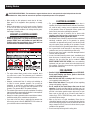 4
4
-
 5
5
-
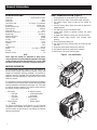 6
6
-
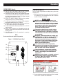 7
7
-
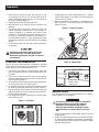 8
8
-
 9
9
-
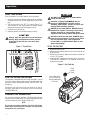 10
10
-
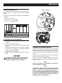 11
11
-
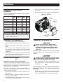 12
12
-
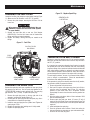 13
13
-
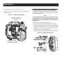 14
14
-
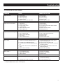 15
15
-
 16
16
-
 17
17
-
 18
18
-
 19
19
-
 20
20
-
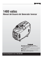 21
21
-
 22
22
-
 23
23
-
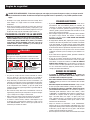 24
24
-
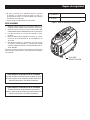 25
25
-
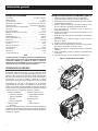 26
26
-
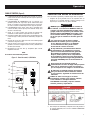 27
27
-
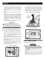 28
28
-
 29
29
-
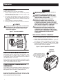 30
30
-
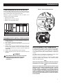 31
31
-
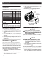 32
32
-
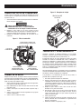 33
33
-
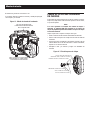 34
34
-
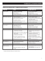 35
35
-
 36
36
-
 37
37
-
 38
38
-
 39
39
-
 40
40


Honeywell 6067 Manual de usuario
- Categoría
- Generadores de poder
- Tipo
- Manual de usuario
- Este manual también es adecuado para
en otros idiomas
- English: Honeywell 6067 User manual