CABINET INSTALLATION INSTRUCTIONS
Step 1. CONFIRM that the carrier’s bill of lading matches the
container and products unloaded from the delivery truck. Inspect the
outside of each container for any indication of potential concealed
damage. Carefully and clearly note any and all damage on the freight
bill before signing.
Paso 1. CONFIRME que el reconocimiento del transportador
corresponde al contenedor y a los productos descargados del camión.
Una vez que el producto es retirado del camión, inspeccione la parte
exterior de cada contenedor para identificar cualquier posible daño
oculto. Anote claramente todos los daños en el certificado de carga
antes de firmar.
Step 2. REVIEW entire contents of envelope titled “Instructions
Enclosed”. Keep this important information in a safe and secure place
as you will need to refer to it often during the installation process.
Paso 2. REVISE el contenido total del sobre de “instrucciones
adjuntas”. Mantenga esta información importante en un lugar seguro
ya que frecuentemente necesitará referirse a la misma durante la
instalación.
RECOMMENDED TOOL LIST
1. Cordless Drill And Fastener Drive Bits
2. Level - 24” Minimum
3. Tape Measure
4. Rubber Mallet / Dead Blow Hammer
5. Pry Bar
6. Large Flat Head Screw Driver
7. Vise-Grips (Needle Nose)
8. Bar Clamps
9. Socket Set
10. Caulk Gun (Optional)
11. Safety Glasses
12. Gloves
LISTA RECOMENDADA DE HERRAMIENTAS:
1. Taladro inalámbrico y brocas de sujeción
2. Nivel – Mínimo de 24 pulgadas
3. Cinta de medir
4. Mazo de caucho / Martillo de golpe seco
5. Barra de palanca
6. Destornillador grande de cabeza plana
7. Agarraderas de prensa (Punta de aguja)
8. Abrazaderas de barra
9. Juego de alvéolos
10. Pistola de calafateo (Opcional)
11. Gafas de seguridad
12. Guantes
Thank you for choosing Royston cabinets for your store. As always, we appreciate your business and
are proud to have you as a customer.
IMPORTANT: These instructions provide general guidance for the installation of Royston-built cabinets.
Your unique project may require some particular steps not included here. Please call 800-334-1766 for
further assistance.
IMPORTANTE: Esta guía provee instrucciones generales para la instalar los gabi-netes Royston.
Algunos de los pasos para algún proyecto especial de instalación podrían no estar incluidos. Favor
llamar al 800-334-1766 para guía adicional.
1.
2.

3.
4.
5.
6.
7.
CABINET INSTALLATION INSTRUCTIONS
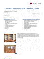
Step 3. CLEAR the installation area to ensure project continues safely
and easily.
Paso 3. Despeje el área de instalación—un área limpia de trabajo hace
más fácil y seguro su proyecto de instalación.
Step 4. UNCRATE all cabinets and move to the installation area.
Arrange everything according to counter layout. Please note: DO NOT
remove drawings attached to cabinets until installation is complete.
Paso 4. Desempaque los gabinetes y llévelos hacia el área de
instalación. Dispóngalos de acuerdo con la colocación del mostrador.
NOTA: No retire las ilustraciones adheridas a los gabinetes hasta que
la instalación esté terminada.
Step 5. CHECK that any loose parts such as fillers and hardware are
accounted for and stored separately from packaging materials. These
items are used in multiple areas during installation and are shipped in
bulk. BE CAREFUL NOT to lose loose parts when disposing of any
packaging material.
Paso 5. Es importante encontrar todas las partes sueltas (rellenos de
gabinete, ferretería miscelánea, etc.). Estos artículos son usados en
multiples áreas y usualmente despachados en cantidad. NO pierda
estos artículos cuando deseche el material de empaque.
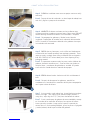
Step 6. SCREW cabinet levelers clockwise until flush with bottom of
base.
Paso 6. Después de desempacar los gabinetes, atornille los
niveladores en el sentido de las manecillas del reloj hasta emparejarlos
con la parte inferior de la base.
Step 7. If using stainless steel cabinet legs, thread clockwise into base
corners until tight. Then, adjust leg to minimum height position. If
using skirts, adjust legs to 6 1/2” (min) from the bottom of cabinet.
Paso 7. Si está usando patas de gabinete de acero inoxidable, aterraje
en el sentido de las manecillas del reloj en las esquinas de la base
hasta que estén ajustadas. Luego, ajuste la pata a la posición de
mínima altura. Si está usando guardapiés, ajuste las patas a 6 pulgadas
y media (mínimo) desde la parte inferior del gabinete.

CABINET INSTALLATION INSTRUCTIONS
8.
9.
10.
11.
12.
Step 8. ARRANGE all cabinets according to provided floorplan.
Paso 8. Disponga los gabinetes de acuerdo con el plan del piso.
Step 9. REMOVE all items from cabinets that may interfere with initial
installation such as cabinet bottom shelf, adjustable shelves, fillers, some
cup dispensers, and boxes containing cup covers and condiment trays.
Move these items to a safe, convenient area outside the installation area.
Mark each piece clearly so you can easily return every item to the correct
cabinet.
Paso 9. Retire de los gabinetes artículos que pudieran interferir con
la insta-lación (repisa inferior delgabinete, repisas ajustables, rellenos,
algu-nos dispensadores y cajas de recipientes que contienen tapas de
re-cipientes y bandejas de condimentos). Muévalos a un área segura y
conveniente. Márquelos para que los pueda retornar al gabinete co-rrecto.
Step 10. LO CATE all possible plumbing or electrical obstructions.
Slight modifications to those connections may be required to ensure
proper cabinet fit.
Paso 10. Localice posibles obstrucciones de plomería o eléctricas.
Se podrí-an requerir ligeras modificaciones para asegurar un ajuste
apropia-do de los gabinetes.
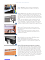
Step 11. REMOVE cabinet base knockouts BETWEEN all cabinets.
DO NOT remove knockouts on END cabinets.
Paso 11. Retire los bloques de las bases de los gabinetes que hay
entre todos los gabinetes. No retire los bloques de los gabinetes de
extremo.
Step 12. START cabinet leveling at floor high point. If no high point
is evident, start at the end of a counter and at the wall (if there is
one). Use leveling legs to level cabinets side to side and front to back.
Continue process until all cabinets are level and properly aligned. Verify
all fronts and rears are flush and seams between cabinets are straight.
Paso 12. Comience el nivelado de los gabinetes en el punto más alto
del pi-so. Si no se puede encontrar el punto más alto, comience al final
de un mostrador, en la pared si existe una. Use piezas de nivelación para
nivelar los gabinetes lado con lado y frente con respaldo. Con-tinúe el
proceso hasta que todos los gabinetes estén nivelados y apropiadamente
alineados. Verifique que los frentes y los respaldos estén emparejados y
que las uniones entre los gabinetes estén dere-chas.

Information in this document is the proprietary property of Royston LLC and is subject to change without notice. Reproduction in
any manner without written permission of Royston LLC is absolutely forbidden. Royston LLC reserves the right to make changes in
product design or detail and to discontinue any product or material without notice.
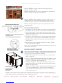
TIE STRAP INSTALLATION
1. Line cabinets up with each other, then remove the loose bottom in
each cabinet and adjust levelers until top surfaces and fronts align.
2. Check base alignment. If base needs adjustment to be flush with
adjacent base, loosen the four bolts on one end and move base as
needed, then tighten bolts.
3. Take (part 1) and slide strap (part 4) through slots in both counters,
then secure (part 1) to top using (2) particle board screws (part 2).
4. Slide (part 3) on strap and secure to top using (2) particle board
screws (part 2).
5. Rotate screw on (part 3) to lock strap (part 4) in place. Tighten
screw to lock counters together.
Note: Two tie straps should be used for each cabinet joint; one in the
front and one in the back.
BOLTING CABINETS TOGETHER
Note: Bolting cabinets together is recommended for permanent instal-
lation, but if you have a tendency to rearrange counters from time to
time, you may want to exclude this operation.
1. Double-check cabinet joint to see if top surfaces and fronts align.
Adjust if necessary.
2. Drill a 1/4” diameter hole through the ends of the cabinets as close
to the front and top as is practical. Bolt cabinets together using a
1/4-20 x 1/2” machine screw and hextite nut.
3. Check base alignment. If base needs adjustment to be flush with
adjacent base, loosen the four bolts on one end and move base as
needed, then tighten bolts.
4. Drill (2) 1/4” diameter holes in the base ends of the cabinets about
3” up from the bottom and as close to the front and back as is
practical. Bolt bases together using (2) 1/4-20 x 1/2” machine
screws and hextite nuts.
2. Phillips drive #10 x .5 pan head wood screw
3. Tensioning screw
4. Connecting strap (see detail B below)
2
3
4
14.
13.
CABINET INSTALLATION INSTRUCTIONS
Royston LLC One Pickroy Road Jasper, GA 30143 800.334.1766 770.735.3456 770.735.4017fax roystonllc.com
Step 13. REFER to site plan in order to identify filler and top
locations. Install as required.
Paso 13. Refiriéndose al plan del lugar, identifique las ubicaciones de
relleno y de tapas. Instale según sea requerido.
Step 14. FASTEN cabinets together by using tie straps or bolts, see
diagram on the left. Please note that cabinet connectors are not
included for solid-surface tops or non-Royston manufactured tops.
Paso 14. Sujete los gabinetes juntos—vea la hoja de instrucciones
presentada arriba.
Use two tie straps
per cabinet thread-
ing thru slots in
area shown.
©Royston LLC. All rights reserved. #22027553 081815
-
 1
1
-
 2
2
-
 3
3
-
 4
4