Craftsman 917.773752 El manual del propietario
- Categoría
- Herramientas de jardín
- Tipo
- El manual del propietario
Este manual también es adecuado para

Owner's Manual
CRRFTSMRN°
6.75 HORSEPOWER
22 INCH CUT
EL
E m
Model No.
917,773752
E
o Safety
,, AssembWy
,, Operation
@
® EspaSo_
,, Repair Parts
Read and follow all
Safety Rules and Instructions
before operating this equipment.
Sears, Roebuck and Co., Hoffman Estates, IL 60179
Visit our Craftsman website: www.sears.com/craftsman

Warranty ................................................... 2
Safety Rules .......................................... 2-4
Assembly .................................................. 5
Operation ............................................... 6-8
Maintenance Schedule ............................. 9
Maintenance ........................................ 9-12
Product Specifications ............................ 9
Service and Adjustments ................... 13-14
Storage ................................................... 15
Troubleshooting ...................................... 16
Repair Parts ....................................... 34-41
Parts Ordering ......................... Back Cover
LIMITED TWO YEAR WARRANTY ON CRAFTSMAN WEEDTRIMMER
For two years from date of purchase, when this Craftsman VVeedtrimmer is maintained,
lubricated, and tuned up according to the operating and maintenance instructions in the
owner's manual, Sears will repair free of charge any defect in material or workmanship.
If this Craftsman Weedtrimmer is used for commercial or rental purposes, this warranty
applies for only 90 days from the date of purchase.
This Warranty does not cover:
Expendable items which become worn during normal use, such as rotating lines,
belts, air cleaners and spark plug.
Repairs necessary because of operator abuse or negligence, including bent crank-
shafts and the failure to maintain the equipment according to the instructions con-
tained in the owner's manual.
Warranty service is available by returning the Craftsman Weedtrimmer to the nearest
Sears Service Center in the United States. This warranty applies only while this product
is in use in the United States.
This Warranty gives you specific legal rights, and you may also have other rights which
vary from state to state.
Sears, Roebuck and Co., Dept. 817 WA, Hoffman Estates, IL 60179
_I,WARNmNG: This trimmer is equipped with an internal combustion engine and should
not be used on or near any unimproved forest-covered, brush-covered or grass-covered
land unless the engine's exhaust system is equipped with a spark arrester meeting ap-
plicable local or state laws (if any). If a spark arrester is used, it should be maintained in
effective working order by the operator.
In the state of California the above is required by law (Section 4442 of the California
Public Resources Code). Other states may have similar laws. Federal laws apply on
federal lands. A spark arrester for the muffler is available through your nearest Sears
service center (See the REPAIR PARTS section of this manual).

SAFETYGLASSES
The operation of any trimmer can result in foreign objects thrown into
the eyes, which can result in severe eye damage. Always wear safety
glasses or eye shields while operating your trimmer or performing any
adjustments or repairs. We recommend a wide vision safety mask over
spectacles or standard safety glasses.
L GENERAL OPERATmON
* Read, understand, and follow all instruc-
tions on the machine and in the manual
before starting. Be thoroughly familiar
with the controls and the proper use of
the machine before starting.
Do not put hands or feet near or under
rotating parts.
Keep all parts of your body away from
muffler and spinning line. A hot muffler
can cause serious burns.
, Only allow responsible individuals, who
are familiar with the instructions, to oper-
ate the machine.
, Stay away from breakable objects, such
as house windows, auto glass, green-
houses, etc.
, Clear the area of objects such as rocks,
toys, wire, bones, sticks, etc., which
could be picked up and thrown by the
spinning lines.
, Be sure the area is clear of other people
before trimming, particularly small chil-
dren and pets. Stop machine if anyone
enters the area.
, Wear appropriate clothing such as a
long-sleeved shirt or jacket. Also wear
long trousers or slacks. Do not wear
shorts.
, Do not wear loose clothing which could
get caught in this equipment.
, Do not operate the machine when bare-
foot or wearing open sandals. Always
wear work gloves and sturdy footwear.
Leather work shoes or short boots work
well for most people. These will protect
the operator's ankles and shins from
small sticks, splinters, and other debris,
and improve traction.
, Do not pull machine backwards unless
absolutely necessary. Always look down
and behind before and while moving
backwards.
Do not operate the machine without
proper guards, plates or other safety
protective devices in place.
See manufacturer's instructions for
proper operation and installation of
accessories. Only use accessories ap-
proved by the manufacturer.
Never use blades, wire, or flailing de-
vices. This unit is designed for line trim-
mer use only. Use of other accessories
or attachments will increase the risk of
injury.
Stop the rotating trimmer head when
crossing gravel drives, walks, or roads.
Wait for the cutting lines to stop rotating.
Stop the engine (motor) whenever you
leave the equipment and allow it to cool,
before cleaning, repairing or inspecting
the unit. Be sure the trimmer head and
all moving parts have stopped.
Operate only in daylight or good artificial
light.
Do not operate the machine while under
the influence of alcohol or drugs.
Never operate machine in wet grass.
Always be sure of your footing: keep a
firm hold on the handle and walk; never
run.
,, If the equipment should start to vibrate
abnormally, stop the engine (motor) and
check immediately for the cause. Vibra-
tion is generally a warning of trouble.
,, Always wear safety goggles or safety
glasses with side shields when operating
machine.

H. SLOPE OPERATmON
Slopesarea majorfactorrelatedtoslip
andfallaccidentswhichcan resultin
severeinjury.All slopesrequireextracau-
tion. Ifyoufeel uneasyona slope,do not
trim it.
DO:
* Trim across the face of slopes: never up
and down. Exercise extreme caution
when changing direction on slopes.
Remove obstacles such as rocks, tree
limbs, etc.
Watch for holes, ruts, or bumps. Tall
grass can hide obstacles.
DO NOT:
* Do not trim near drop-offs, ditches or
embankments. The operator could lose
footing or balance.
Do not trim excessively steep slopes.
Do not trim on wet grass. Reduced foot-
ing could cause slipping.
HL CHmLDREN
Tragic accidents can occur if the operator
is not alert to the presence of children.
Children are often attracted to the machine
and the trimming activity. Never assume
that children will remain where you last saw
them.
Keep children out of the trimming area
and under the watchful care of another
responsible adult.
Be alert and turn machine off if children
enter the area.
Before and while moving backwards,
look behind and down for small children.
Never allow children to operate the ma-
chine.
Use extra care when approaching blind
corners, shrubs, trees, or other objects
that may obscure vision.
mY. SERVICE
Use extra care in handling gasoline and
other fuels. They are flammable and
vapors are explosive.
Use only an approved container.
Never remove gas cap or add fuel
with the engine running. Allow en-
gine to cool before refueling. Do not
smoke.
Never refuel the machine indoors.
Never store the machine or fuel con-
tainer inside where there is an open
flame, such as a water heater.
Move away from fueling site before
starting engine.
Never run a machine inside a closed
area.
Never make adjustments or repairs with
the engine (motor) running. Disconnect
the spark plug wire, and keep the wire
away from the plug to prevent accidental
starting.
Keep nuts and bolts, especially trimmer
head and engine bolts, tight and keep
equipment in good condition.
Never tamper with safety devices.
Check their proper operation regularly.
Keep machine free of grass, leaves, or
other debris buildup. Clean oil or fuel
spillage. Allow machine to cool before
cleaning or storing.
Stop and inspect the equipment if you
strike an object. Repair, if necessary,
before restarting.
Do not change the engine governor set-
ting or overspeed the engine.
Clean and replace safety and instruction
decals as necessary.
&Look for this symbol to point out
important safety precautions. It means
CAUTION!!! BECOME ALERT!!! YOUR
SAFETY IS INVOLVED.
&WARNING: In order to prevent ac-
cidental starting when setting up, trans-
porting, adjusting or making repairs,
always disconnect spark plug wire and
place wire where it cannot contact spark
plug.
&WARNmNG: Engine exhaust, some
of its constituents, and certain vehicle
components contain or emit chemicals
known to the State of California to
cause cancer and birth defects or other
reproductive harm.
_, CAUTmON: Muffler and other engine
parts become extremely hot during
operation and remain hot after engine has
stopped. To avoid severe burns on contact,
stay away from these areas.

Readthese instructionsandthismanualin
itsentiretybeforeyou attemptto assemble
oroperateyour newtrimmer.
iMPORTANT:Thistrimmerisshipped
WITHOUTOIL ORGASOLINEinthe
engine.
Yournewtrimmerhas beenassembled
atthefactorywith theexceptionofthose
partsleftunassembledforshipping
purposes.All partssuch asnuts,wash-
ers, bolts,etc.,necessarytocompletethe
assemblyhavebeenplacedinthe parts
bag. Toensuresafeand properoperation
ofyourtrimmer,all partsandhardwareyou
assemblemustbe tightenedsecurely.Use
thecorrecttools as necessaryto ensure
propertightness.
When righthand(RH)orleft hand(LH) is
mentionedin thismanual,it meanswhen
you are inthe operatingposition(standing
_@bJ_c_Cs_9::__;_.Separately
TO REMOVE TRIMMER FROM
CARTON
1. Removeloosepartsincludedwith trim-
mer.
2. Cutdowntwoendcornersofcarton
and layendpaneldownfiat.
3. Removeall packingmaterials.
4. Rolltrimmeroutofcarton andcheck
cartonthoroughlyforadditionalloose
parts.
HOW TO SET UPYOUR TRIMMER
TOUNFOLDHANDLE
iMPORTANT:Unfoldhandlecarefullyso
as notto pinchor damagecontrolcables.
1. Loosenhandleknobenoughto allow
upperhandleto be unfoldedfromthe
shippingposition.
2. Raiseupperhandlesectioninto place
on lowerhandleandtightenhandle
knob.
3. Removehandlepaddingholdingtrim-
merheadcontrolbarto upperhandle.
Yourtrimmerhandlecan be adjustedfor
yourtrimmingcomfort. Referto "ADJUST
20 oz. Trimmer Lines
Bottle of oH (2) Sets
(0.!55 diameter
× 18.75 inches long)
Upper handb
Lift up
Handb
knob
Lower
handle

KNOW YOUR TRmMMER
READ THIS OWNER'S MANUAL AND SAFETY RULES BEFORE OPERATING YOUR
TRIMMER. Compare the illustrations with your trimmer to familiarize yourself with the
location of various controls and adjustments. Save this manual for future reference.
understand their
" '"° & @
CAUTION ENGINE OFF
FAST SLOW
FUEL OIL
Throttle control
Trimmer head controUbar
Gasoline cap
Starter handUe
Engine cover
Air fluter
HandUe knob Primer
Engine oHcap w/dipstick
Muffler
cover
Trimmer head
mMPORTANT: This trimmer is shipped Trimmer Hne
WITHOUT OIL OR GASOLINE in the
Trimmer head control bar - must be
held down to the handle to engage trimmer
head. Release to stop the trimmer head.
Primer - pumps additional fuel from the
carburetor to the cylinder for use when
starting a cold engine.
Throttle control - used for starting and
stopping the engine and allows you to
select either fast or slow engine speed.
Starter handle - used for starting the

SAFETYGLASSES
The operation of any trimmer can result
in foreign objects being thrown into the
eyes, which can result in severe eye dam-
age. Always wear safety glasses or eye
shields while operating your trimmer or
performing any adjustments or repairs. We
recommend a wide vision safety mask over
spectacles or standard safety glasses.
TO ADJUST TRIMMING HEmGHT
_CAUTmON: Stop the engine and wait for
all moving parts to stop. Disconnect spark
plug wire from spark plug and place wire
where it cannot come in contact with plug.
The height of cut can be set to six (6) dif-
ferent positions ranging from 1-1/2 inches
to 3 inches. Recommended cutting height
for the average yard is 2 inches.
1. To adjust trimming height, push in the
locking plate tab and move trimmer
head up or down to desired position.
2. Release tab and be sure head is
locked into one of the six (6) height
positions.
HOW TO USE YOUR TRmMMER
ENGmNE SPEED
The engine speed is controNed by a
throttle located on the side of the upper
handle. Fast position is for starting and
normal trimming. Slow is for light trimming
and fuel economy. Stop is for stopping the
engine.
Adj
Trimmer
Head
Locking
Plate Tab
TRIMMER HEAD DRIVE CONTROL
Your trimmer is equipped with a trimmer
head drive control bar which will require
the operator to be positioned behind the
trimmer handle to operate the trimmer.
* Trimmer head rotation is controlled by
holding the trimmer head control bar
down to the handle.
* Trimmer head rotation will stop when
the control bar is released.
BEFORE STARTING ENGmNE
ADD OIL
Your trimmer is shipped without oil in the
engine. For type and grade of oil to use,
see "ENGINE" in the Maintenance section
of this manual.
A CAUTION: DO NOT overfill engine with
oil, or it will smoke on startup.
1. Be sure trimmer is level and area
around oil fill is clean.
2. Remove oil dipstick from oil fill spout.
Make sure that rim of spout is clean.

3. Youreceivea 20 oz.containerof oil
with theunit. Slowlypour3/4 (15oz.)
oftheoil fromthecontainerdownthe
oilfill spout intotheengine.
4. Waitone minuteto allowoil tosettle.
Insertandtightendipstick,then re-
moveitto checkoillevel.
5. Continueaddingsmallamountsof
oiland recheckingthedipstickuntilit
readsfull. DONOToverfill,orengine
willsmokeon startup.
6. Alwaysbesureto retightenoildipstick
beforestartingengine.
• Check oil level before each use. Add oil
if needed. Fill to full line on dipstick.
• Change the oil after every 25 hours of
operation or each season. You may
need to change the oil more often under
dusty, dirty conditions.
ADD GASOUNE
• Fill fuel tank. Use fresh, clean, regular
unleaded gasoline with a minimum of
87 octane. Do not mix oil with gasoline.
Purchase fuel in quantities that can be
used within 30 days to assure fuel fresh-
ness.
AI:_WARNmNG: Experience indicates that
alcohol blended fuels (called gasohol or
using ethanol or methanol) can attract
moisture which leads to separation and
formation of acids during storage. Acidic
gas can damage the fuel system of an
engine while in storage. To avoid engine
problems, the fuel system should be
emptied before storage of 30 days or
longer. Drain the gas tank, start the
engine and let it run until the fuel lines
and carburetor are empty. Use fresh fuel
next season. See Storage Instructions for
additional information. Never use engine
or carburetor cleaner products in the fuel
tank or permanent damage may occur.
Al_ CAUTmON: Fill to bottom of gas tank
filler neck. Do not overfill. Wipe off any
spilled oil or fuel. Do not store, spill or use
gasoline near an open flame.
Gasoline filler cap
Engine oil cap
TO START ENGINE
1. To start a cold engine, push primer
three (3) times before trying to start.
Use a firm push. This step is not
usually necessary when starting an
engine which has already run for a few
minutes.
2. Move throttle control lever to fast posi-
tion.
3. Hold upper handle firmly and pull
starter handle quickly. Do not allow
starter rope to snap back.
TO STOP ENG(NE
• To stop engine, move throttle control
lever to stop position.
NOTE: In cooler weather it may be
necessary to repeat priming steps. In
warmer weather overpriming may cause
flooding and engine will not start. If you
do flood engine, wait a few m_ before
Throttle -'_\
controu
Starter '_' "_!_!, //
handle _,.. /_L
Set the throttle control in the fast posi-
tion. If the weeds or grass are tall and
thick, operate the trimmer at a slower
walking speed.
• Frequently clean the underside of the
trimmer to remove any grass build up.
Keep top of engine around starter clear
and clean of grass clippings and chaff.
This will help engine air flow and extend
engine life. See "TO REMOVE ENGINE
COVER" in the Maintenance section of
this manual.
• For best results and longer lasting
line, use the ends of the line to do the
cutting. This is easily done by moving
slowly through very thick and heavy
weeds.
• Use the left side of trimmer when trim-
ming along fences, walls, fiowerbeds
and other such objects.
• If trimmer lines become too short, it will
take longer to complete the job. If trim-
mer lines are worn to less than half their
original length, they should be replaced.
See "TO REPLACE TRIMMER LINE" in
the Maintenance section of this manual.
Trimmer head contact with concrete, as-
phalt or other hard surfaces may cause
premature wear of the ball on bottom of
trimmer head.

MAINTENANCE SCHEDULE
,LL, O ES
REGULAR SERVICE
T Check for Loose Fasteners I/ I_
R Clean Trimmer I_ I/
I
M Clean Under Engine Cover I/2
Check Drive Belt / Pulleys
v'
R Check / Replace Trimmer Lines 1_3
Check Engine Oil Level I/
E Change Engine Oil I/1,2
Clean Air Filter I_ 2
I Inspect Muffler
Clean or Replace Spark Plug I_
Replace Air Filter Paper Cartridge 1_2
1 - Change more often when operating under a heavy load or in high ambient temperatures,
2 - Service more often when operating in dirty or dusty conditions.
3 - Replace trimmer lines when they have worn to half their original length.
GENERAL RECOMMENDATmONS
The warranty on this trimmer does not
cover items that have been subjected to
operator abuse or negligence. To receive
full value from the warranty, operator must
maintain trimmer as instructed in this
manual.
Some adjustments will need to be made
periodically to properly maintain your unit.
All adjustments in the Service and Adjust-
ments section of this manual should be
checked at least once each season.
Once a year, replace the spark plug and
replace air filter element. A new spark
plug and clean/new air filter element
assure proper air-fuel mixture and help
your engine run better and last longer.
Follow the maintenance schedule in this
manual.
BEFORE EACH USE
1. Check engine oil level.
2. Check for loose fasteners.
3. Clean under engine cover.
LUBRmCATmON
To pro{ong the useful life of your trimmer,
change engine oil as recommended in this
section of Owner's Manual.
mMPORTANT: Do not oil or grease plastic
wheel bearings. Viscous lubricants will
attract dust and dirt that will shorten the
life of the self- lubricating bearings. If you
feel they must be lubricated, use only
a dry, powdered graphite type lubricant
sparingly.
PRODUCT SPECmFmCATmONS
Serial No.
Date of Purchase:
Gasoline Type: Unleaded Regular
Gasoline Capacity: 1.25 Quarts
Oil Type:
(APFSF-SJ)
Oil Capacity:
SAE 30 (Above 32 -°F)
SAE 5W-30 (Below 32-°F)
20 ounces
Spark Plug: Champion RJ19LM4
(Gap: .045")
Trimmer Line Diameter:.155 inch
Trimmer Line Length: 18.75 inches
The model and serial numbers will be
found on a decal attached to the rear of
the trimmer. Record both serial number
and date of purchase in the space pro-
vided above.

Alwaysobservesafetyruleswhenper-
formingany maintenance.
TmRES
Keeptiresfreeof gasoline,oil, or insect
controlchemicalswhichcan harm rub-
ber.
Avoidstumps,stones,deepruts,sharp
objectsand otherhazardsthat may
causetire damage.
TR(MMERL(NE
For best results, replace trimmer lines
when they have worn to half their original
length. Use .155 inch diameter trimmer
line. Cut new trimmer line length to 18-3/4
inches. After new line is installed on
trimmer head, check all lines so they do
not vary more then one (1) inch in length.
This is important to make sure the trim-
mer head is balanced and will not vibrate
abnormally.
AWARNmNG: Use only the specified
trimmer line. Do not use other materials
such as wire, string, rope, etc. Wire can
break off during trimming and become a
dangerous missile that can cause serious
injury.
TO CUT LINE TO PROPER LENGTH
NOTE: Trimmer line pre-cut to proper
length is available for this unit; see the
Repair Parts section of this manual.
If trimmer line is purchased in bulk, it must
be cut to 18-3/4 inches before using. Use
the built-in length guage as follows:
1. From front of trimmer, place the end of
spooled trimmer line at the mark on the
side of the debris shield as shown.
2. Wrap trimmer line around front of chas-
sis cover to other side and cut at the
"22" mark (your unit's width of cut).
Chassis cover
TO REPLACE TRIMMER LINE
1. Disconnect spark plug wire from spark
plug and place wire where it cannot
come in contact with spark plug.
2. Remove worn trimmer line from line
carrier plate.
3. Fold new, cut to length, trimmer line
in half and insert folded end through
carrier plate opening to back side of
retainer clip.
4. With folded end of line at back side of
retainer clip, pull line outward until line
is fully seated under the retainer clip.
5. Repeat on other side of carrier plate.
6. Check all lines to be sure they are the
same length.
7. Reconnect spark plug wire to spark
plug.
Trimmer
line
\\
\
Carrier plate
opening
Wrap
line
around
Debris New
shield End of trimmer
mark spooled line line
clip
10

LUBRICATION
Useonlyhighqualitydetergentoil rated
with APIserviceclassificationSF-SJ. Se-
lectthe oil"sSAEviscositygradeaccord-
ingtoyourexpected operating tempera-
ture.
SAE VISCOSITY GRADES
] I I i
I'T"I 4oIoo Ioo r,oo
; ANT,O,;ATEOO;OREN XTO,LO E
oilvisc chaltle
NOTE: Although multi-viscosity oils
(5W30, 10W30 etc.)improve starting in
cold weather, these multi-viscosity oils will
result in increased oil consumption when
used above 32°R Check your engine oil
level more frequently to avoid possible
engine damage from running low on oil.
Change the oil after every 25 hours of
operation or at least once a year if the unit
is not used for 25 hours in one year.
Check the crankcase oil level before
starting the engine and after each five (5)
hours of continuous use. Tighten oil plug
securely each time you check the oil level.
TO CHANGE ENGINE OIL
NOTE: Before tipping trimmer to drain oil,
drain fuel tank by running engine until fuel
tank is empty.
1. Disconnect spark plug wire from spark
plug and place wire where it cannot
come in contact with spark plug.
2. Remove engine oil cap; lay aside on a
clean surface.
3. Tip trimmer on its side as shown and
drain oil into a suitable container. Rock
trimmer back and forth to remove any
oil trapped inside of engine.
4. Wipe off any spilled oil from trimmer
and side of engine.
5. Fill engine with oil (See "ADD OIL:' in
the Operation section of this manual).
6. Replace engine oil cap.
7. Reconnect spark plug wire to spark
plug.
Container
AIR FILTER
Your engine will not run properly and may
be damaged by using a dirty air filter. Re-
place the air filter every 100 hours of op-
eration or every season, whichever occurs
first. Service air cleaner more often under
dusty conditions. Do not wash air filter.
TO CHANGE AIR FILTER
1. Remove the air filter by turning clock-
wise to the stop and pull away from
collar.
2. Remove filter from inside of cover.
3. Clean the inside of the cover and the
collar to remove any dirt accumulation.
4. Insert new filter into cover.
5. Put air filter cover and filter into collar
aligning the tab with the slot.
6. Push in on cover and turn counter-
clockwise to tighten.
Collar
Clip
Turn
clockwise
to
remove
Slot
Air filter
Tab
Air filter cover
Turn
counter°
clockwise to tighten
11

MUFFLER
Inspect and replace corroded muffler as it
could create a fire hazard and/or damage.
SPARK PLUG
Replace spark plugs at the beginning of
each mowing season or after every 100
hours of operation, whichever occurs
first. Spark plug type and gap setting are
shown in "PRODUCT SPECIFICATIONS"
in Maintenance section of this manual.
mMPORTANT: For best performance, keep
trimmer free of built-up grass and trash.
Clean the underside of your trimmer after
each use.
ACAUTmON: Disconnect spark plug wire
from spark plug and place wire where it
cannot come in contact with the spark
plug.
• Turn trimmer on its side. Make sure air
filter and carburetor are up. Clean the
underside of your trimmer by scraping to
remove build-up of grass and trash.
• Clean engine often to keep trash from
accumulating. A clogged engine runs
hotter and shortens engine life.
• Keep finished surfaces and wheels free
of all gasoline, oil, etc.
• We do not recommend using a gar-
den hose to clean trimmer unless the
electrical system, muffler, air filter and
carburetor are covered to keep water
out. Water in engine can result in short-
ened engine life.
CLEAN UNDER ENGmNE COVER
Clean under engine cover before each
use, or more frequently in heaw cutting or
dirty conditions. Engine cover screen and
engine air intake screen must be kept free
of dirt and chaff to prevent engine damage
from overheating.
Be sure engine is cool before cleaning.
1. Unscrew knob on top of cover.
2. Lift cover up and away from engine.
3. Clean cover and cover screen thor-
oughly.
4. Clean top of engine and air intake
screen.
5. Replace engine cover and tighten
knob securely. Be sure the front tabs of
engine cover are located in the slots in
engine housing.
Knob
Engine cover
/
Starter
rope
Threaded
stud
Engine
cove r
screen
Air intake screen
Housing slots
12

_, CAUTmON: Before performing any
service and adjustments:
1. Stop engine.
2. Make sure the rotating lines and all
moving parts have completely stopped.
3. Disconnect spark plug wire from spark
plug and place where it cannot come in
contact with plug.
TO ADJUST TBI_,_MmNG HEmGHT
See "TO ADJUST TRIMMING HEIGHT" in
the Operation section of this manual.
TO ADJUST HANDLE
The upper handle may be adjusted to dif-
ferent height positions.
* Loosen handle knob only enough to
allow the upper handle to pivot to the
desired position.
* Tighten handle knob securely.
NOTE: The handle knob and bolt may be
reversed for left handed operation.
Upper handUe
II
,/
TO REI\,_OVE/BEPLACE TBmI\,_MEB HEAD
DBmVE BELT
1. Remove screw at front of chassis cover.
2. Lift cover up and away from trimmer.
3. Remove the two (2) screws on sides of
Chassis
cover
trimmer securing the debris shield.
4. Turn trimmer on its side with carburetor
and fuel cap up.
5. Remove the two (2) screws on under-
side of trimmer securing the debris
shield.
6. Slide the debris shield rearward and
remove.
7. Remove belt from engine pulley on
crankshaft.
gine
pulley
Handle knob
13

8. Remove belt from trimmer head pulley.
9. Note the position of the control cable
and idler return spring, then remove
idler assembly from chassis and re-
move belt and idler from trimmer.
10. Remove belt from idler assembly by
removing bottom belt keeper and idler
pulleys.
11 .Assemble new belt, idler pulleys and
bottom belt keeper to idler bracket.
Tighten pulley bolts securely.
NOTE: Be sure belt is inside top belt
keeper on idler assembly.
Engine pulley
Chassis //-...
/ I /_
/
\
12. Position belt and idler assembly in
trimmer, reconnect idler spring and as-
semble idler to chassis.
13. Install belt around trimmer head pulley
and engine pulley.
14. Replace debris shield and tighten the
four (4) screws securely.
15. Replace chassis cover and tighten
screw securely.
Always use Craftsman replacement parts
to assure proper fit and long life.
Nut
Idler bracket
Spacer
Flatidler
Bottom
., belt
keeper
Fiat idler
Trimmer head pulley
ENGmNE SPEED
Your engine speed has been factory set.
Do not attempt to increase engine speed
or it may result in personal injury. If you
believe that the engine is running too fast
or too slow, take your unit to a Sears or
other qualified service center for repair
and/or adjustment.
Your carburetor has a nonadjustable fixed
main jet for mixture control. If your engine
does not operate properly due to sus-
pected carburetor problems, take your unit
to a Sears or other qualified service center
for repair and/or adjustment.
mlVIPORTANT: Never tamper with the
engine governor, which is factory set
for proper engine speed. Overspeeding
the engine above the factory high speed
setting can be dangerous. If you think
the engine-governed high speed needs
adjusting, take your unit to a Sears or
other qualified service center, which has
proper equipment and experience to make
any necessary adjustments.
14

Immediately prepare your trimmer for stor-
age at the end of the season or if the unit
will not be used for 30 days or more.
When trimmer is to be stored for a period
of time, clean it thoroughly, remove atl dirt,
grease, leaves, etc. Store in a clean, dry
area.
1. Clean entire trimmer (See "CLEAN-
ING" in the Maintenance section of this
manual).
2. Lubricate as shown in the Maintenance
section of this manual.
3. Be sure that a(I nuts, bolts, screws, and
pins are securely fastened. Inspect
moving parts for damage, breakage
and wear. Replace if necessary.
4. Touch up all rusted or chipped paint
surfaces; sand lightly before painting.
HANDLE
You can fold your trimmer handle for stor-
age.
Loosen handle knob enough to allow
upper handle to be folded forward.
(MPORTANT: When folding the handle for
(MPORTANT: It is important to prevent
gum deposits from forming in essential
fuel system parts such as carburetor, fuel
filter, fuel hose or tank during storage.
Also, experience indicates that alcohol
blended fuels (called gasohol or using
ethanol or methanol) can attract moisture
which leads to separation and formation
of acids during storage. Acidic gas can
damage the fuel system of an engine
while in storage.
1. Drain the fuel tank.
2. Start the engine and let it run until the
fuel lines and carburetor are empty.
Never use engine or carburetor cleaner
products in the fuel tank or permanent
damage may occur.
Use fresh fuel next season.
NOTE: Fuel stabilizer is an acceptable
alternative in minimizing the formation
of fuel gum deposits during storage.
Add stabilizer to gasoline in fuel tank or
storage container. Always follow the mix
ratio found on stabilizer container. Run
engine at least 10 minutes after adding
stabilizer to allow the stabilizer to reach
the carburetor. Do not drain the gas tank
and carburetor if using fuel stabilizer.
ENG(NE O(L
Drain oil (with engine warm) and replace
with clean engine oil. (See "ENGINE" in
the Maintenance section of this manual).
CYUNDER
1. Remove spark plug.
2. Pour one ounce (29 ml) of oil through
spark plug hole into cylinder.
3. Pull starter handle slowly a few times
to distribute oil.
4. Replace with new spark plug.
Handle knob
storage or transportation, be sure to fold
the handle as shown or you may damage
the control cables.
FUEL SYSTEM
OTHER
* Do not store gasoline from one season
to another.
* Replace your gasoline can if your can
starts to rust. Rust and/or dirt in your
gasoline will cause problems.
If possible, store your unit indoors and
cover it to give protection from dust and
dirt.
Cover your unit with a suitable protective
cover that does not retain moisture. Do
not use plastic. Plastic cannot breathe,
which allows condensation to form and
will cause your unit to rust.
(MPORTANT: Never cover trimmer while
15

TROUBLESHOOTmNG
CAUSEPROBLEM
Does not start
Clean/replace air f
Loss of power
Excessive
Vibration
Starter rope hard
f,_ rm_i
Loss of head
arive
Hard to push
Poor trimming
performance
Trimmer head
does not
retain line
.
ter.
2. Out of fuel.
3. Stale fuel.
4. Water in fuel.
5. Spark plug wire is
disconnected.
6. Bad spark plug.
7. Throttle control lever not
in correct position
(if eq13t_ped).
1. Dirty air filter.
2. Buildup of grass, leaves,
and trash under trimmer.
3. Too much oil in engine.
4. Walking speed too fast.
1. Lines uneven or broken.
2. Loose nuts or bolts.
1. Bent engine crankshaft.
1. Belt not driving.
1. Handle height position not
1. Trimmer line length is
too short.
2. Throttle control lever not
in correct position
(!f eq'__._ppe_).
1. Trimmer line not
properly installed.
2. Broken line retainer clip.
3. Incorrect size of
CORRECTmON
Dirty air filter. 1.
2. Fill fuel tank.
3. Drain tank and refill with
fresh clean fuel.
4. Drain fuel tank and
carburetor and refill tank
with fresh gasoline.
5. Connect wire to plug.
6. Replace spark plug.
7. Move throttle lever to FAST
position.
1. Clean/replace air filter.
2. Clean underside of trimmer
and trimmer head.
3. Check oil level.
4. Trim at slower walking
1. Check trimmer lines.
2. Check all hardware,
including engine bolts.
1. Contact a Sears or other
1. Put belt on pulleys or
replace belt it broken.
1. Adjust handle height
to cult.
1. If line is worn or broken to
half original length,
replace line.
2. Move throttle lever to FAST
position.
1. Follow instructions in
Maintenance section.
2. Replace string carrier plate
assembly.
3. Use .155 diameter
16

lo DEGREES
Operate a trimmer across the face
of slopes, nevor up or down sWop÷so
15 DEGREES

Especificaciones deUProducto ....................... 26
Servicio y Adjustes ................................... 30-31
AImacenamiento ............................................ 32
Udentificaci6n de proMemas ........................... 33
Partes de repuesto ..................... Vea e[ manual
ingU6sdeUdue_o
Orden de Partes ............................... Contratapa
GARANTiA UMFADA DE DOS A[/OS PARA LA RECORTADORA PARA MALA HERBA PARA
MALA HERBA CRAFTSMAN
Por dos (2) a_os, a partir de Uafecha de compra, cuando esta recortadora para maUahierba Crafts-
man se mantenga, Uubrique y afine segun Uasinstrucciones para Uaoperaci6n y eUmantenimiento
en eUmanuaU deUdue_o, Sears reparara gratis todo defecto en eUmateriaUy Uamano de obra.
Si Uarecortadora para maUahierba Craftsman se usa para fines comerciaUes o de arriendo, esta
garantia s61o se aplica por noventa (90) dias a partir de la fecha de compra.
Esta Garantia no cubre:
o Articulos que se desgastan durante el uso normal tales como las lineas rotatorias, las correas,
los filtros de aire y las bujias.
Reparaciones necesarias debido al abuso o a la negligencia del operador, induy6ndose a los
cigOe_ales doblados y a la falta de mantenimiento del equipo segun las instrucciones que se
induyen en el manual del due_o.
El servicio de garantia esta disponible al devolver la recortadora para mala hierba Craftsman al
Centro de Servicio Sears mas cercano en los Estados Unidos. Esta garantia se aplica solamente
mientras el producto este en uso en los Estados Unidos.
Esta Garantia le otorga derechos legales especificos, y puede que tambi6n tenga otros derechos
que varian de estado a estado.
Sears, Roebuck and Co., Dept. 817 WA, Hoffman Estates, Illinois 60179
dI_ADVERTENCIA: Este recortadora viene equipado con un motor de combusti6n interna y no se
debe usar sobre, o cerca, de un terreno no desarrollado cubierto de bosques, de arbustos o de
cesped, o menos que el sistema de escape del motor venga equipado con un amortiguador de
chispas que cumpla con las leyes locales o estatales (si existen). Si se usa un amortiguador de
chispas, el operador debe mantenedo en condiciones de trabajo eficientes.
En el estado de California, la ley exige Io anterior (Secci6n 4442 del "California Public Resources
Code"). Otros estados pueden contar con otras leyes parecidas. Las leyes federales se aplican en
la tierras federales. Su Centro de Servicio Sears mas cercano tiene disponible amortiguadores de
chispas para el silenciador. (Vea la secci6n de Partes de Repuesto en el manual Ingl6s del due_o.)
18

&
SEGURIDAD
&
La operaci6n de cualquier recortadora puede hacer que salten objetos
extra_os dentro de sus ojos, Io que puede producir da_os graves en 6stos.
Siempre use anteojos de seguridad o protecci6n para los ojos mientras opere
su recortadora o cuando haga ajustes o reparaciones. Recomendamos una
mascara de seguridad de visi6n amplia, para uso espejuelos o anteojos de
seguridad estandarte.
h OPERACI6N GENERAL
o Antes de empezar, debe familiarizarse
completamente con los controles y el uso
correcto de la maquina. Para esto, debe leer
y comprender todas las instruceiones que
aparecen en la maquina yen los manuales
de operaci6n.
No ponga las manos o los pies cerca o deo
bajo de las partes rotatorias.
o Mantener todas las partes del cuerpo lejos
del silenciador del escape y la I[nea de
rotaci6n. El silenciador caliente puede causar
serias quemaduras.
Permita que solamente las personas re-
sponsables que est6n familiarizadas con las
instrucciones operen la ma,quina.
Mantenerse lejos de objetos que pueden
romperse, como cristales de casa, cristales
del choche, invernaderos, etc.
Despeje el a,rea de objetos tabs como pie-
dras, juguetes, alambres, huesos, palos, etc.
que pueden set recogidos y lanzados pot las
lineas giradoras.
Asegurese que el a,rea no se hallen perso-
nas, y particularmente ni_os peque_os y
cachorros antes de recortar. Pare la ma,quina
si alguien entra en el a,rea.
o Use ropa apropaida, tal como camisa de
manga larga o chaqueta y pantalones largos.
No use pantalones cortos shorts.
No use ropa suelta, ya que 6sta podr[a atoro
arse en el equipo.
No opere la maquina sin zapatos o con
sandalias abiertas. Use siempre guantes
de trabajo y calzado fuerte. Los zapatos de
trabajo de piel o botas cortas son apropiados
para la mayor[a de las personas. Estos no
s61oprotegeria,n los tobillos y espinellas del
operador de peque_as ramas, astillas y otros
desperdicios, sino que adema,s mejorara,n la
tracci6n.
o No tire de la ma,quina hacia atra's a menos
que sea absolutamente necesario. Mire
siempre hacia abajo y hacia detra,s antes y
mientras que se mueve hacia atra,s.
o No opere la maquina sin los respectivos
resguardos, placas u otros aditamentos
dise_ados para su protecci6n y seguridad.
o Refi6rase alas instrucciones del fabricante
para el funcionamiento e instalaci6n de
accesorios. Use unicamente accesorios apro-
bados pot el fabricante.
o Nuca utilice cuchillas, cables o dispositivos
tipo mayal. Esta unidad esta,proyectada para
fucionar solamente con una I[nea de recorta-
dora. La utilizaci6n de cualquier otto material,
acessorio o dispositivo secundario aumenta
el riesgo de lesi6nes y da_os a la propiedad.
Detenga la cabeza giratoria de la recortadora
cuando cruce pot calzadas, calles o caminos
de grava. Espere que las cuerdas de corte
paten de giran
Pare el motor siempre que tenga que dejar el
equipo, antes de limpiar, reparar o inspec-
cionar la unidad. Asegurese de que la cabeza
de la recortadora y todas las partes en movo
imiento se hayan detenido.
Opere solamente con luz del d[a o con una
buena luz artificial.
No opere la ma,quina bajo la influencia del
alcohol o de las drogas.
Nunca opere la maquina cuando la hierba
este mojada. Asegurese siempre de tenet
buena tracci6n en sus pies; mantenga el
mango firmemente y camine; nunca corra.
Si el equipo empezara a vibrar de una
manera anormal, pare el motor y revise de
inmediato para averiguar la causa. Genero
almente la vibraci6n suele indicar que existe
alguna aver[a.
Siempre use gafas de seguridad o anteojos
con protecci6n lateral cuando opere la ma-
quina.
19

11.OPERACI6N EN PENDIENTE
Los accidentes ocurren con mas frecuencia en
Uascuesta& Estos accidentes ocurren debido a
resbaUadas o caidas, UascuaUes pueden resuUtar
en graves Uesiones. Operar Uarecortadora en
cuestas requiere mayor concentracidn. Si se
siente inseguro en una cuesta, no Uarecorte.
Sl:
, Puede recortar a trav6s de Uasuperficie de Ua
cuesta, nunca hacia arriba y hacia abajo. Pro°
ceda con extrema precaucidn cuando cambie
de direccidn en Uascuestas.
, Renueva todos Uosobjetos extrafios, taUes
como guijarros, ramas, etc.
, Debe prestar atencidn a hoyos, baches o
protuberancias. Recuerde que Uahierba aUta
puede esconder obstAcuUos.
NO:
, No recorte cerca de pendientes, zanjas o
terrapUenes. EUoperador puede perder Uatraco
ci6n en Uospies o eUequHibrio.
, No recorte cuestas demasiado incHnadas.
, No recorte en hierba mojada. La reduccidn
en Uatraccidn de Uapisada puede causar
resbalones.
111.NINOS
Se pueden producir accidentes trAgicos si el
operador no presta atencidn a la presencia
de los nifios. A menudo, los nifios se sienten
atraidos por la mAquina y por la actividad de
la siega. Nunca suponga que los nifios van a
permanecer en el mismo lugar donde los vio por
Oltima vez.
, Mantenga a los nifios alejados del Area de
la siega y bajo el cuidado estricto de otra
persona adulta responsable.
, Este alerta y apague la maquina si hay nifios
que entran al Area.
, Antes y durante el retroceso, mire hacia
atrAs y hacia abajo para vedficar si hay nifios
pequefios.
, Nunca permita que los nifios operen la mao
qu[na.
, Tenga un cuidado extra cuando se acerque
a esquinas donde no hay visibi]idad, a los
arbustos, Arbo]es u otros objetos que pueden
interferir con su ]inea de visi6n.
IV. SERVlCIO
° Tenga cuidado extra al manejar la gasolina y
los demAs combustibles. Son infiamables y
los gases son explosivos.
Use solamente un envase aprobado.
Nunca remueva la tapa del depdsito de
gasolina o agregue combustible con el
motor funcionando. Permita que el motor
se enfrie antes de volver a poner combuso
tible. No fume.
Nunca vuelva a poner combustible en la
maquina en recintos cerrados.
Nunca almacene la mAquina o el envase
del combustible dentro de algOn lugar en
donde haya una llama expuesta, tal como
la del calentador de agua.
, Alejarse de la zona de abastecimiento del
carburante antes de porter en marcha.
, Nunca haga func[onar una mAqu[na dentro
de un Area cerrada.
, Nunca haga ajustes o reparaciones mientras
el motor est6 en march& Desconecte el
cable de la bujia, y mant6ngalo a cierta
distancia de 6sta para prevenir un arranque
accidental.
, Mantenga las tuercas y los pernos, especiaF
mente los pernos del motor y de la cabeza
de recortes, apretados y mantenga el equipo
en buenas condiciones.
, Nunca manipule de forma indebida los
dispositivos de seguridad. Controle regular°
mente su funcionamiento correcto.
, Mantenga la maquina libre de hierba, hojas u
otras acumulaciones de desperdicio. Limpie
los derrames de aceite o combustible. Per°
mita que la maquina se refresque antes de
limpiarla o almacenarla.
Pare e ]nspeccione el equipo s] le pega a un
objeto. RepArelo, si es necesario, antes de
hacerlo arrancar.
, No cambie el ajuste del regulador del motor
ni exceda su velocidad.
, Limpiar y sustituir las calcomanias relativas a
instrucciones y seguridad cuando necesario.
Ai:_Busque este simbolo que sefiala las precauo
ciones de seguridad de importancia. Quiere
decir - ii iATENCION!!!iiiESTE ALERTO!!! SU
SEGURIDAD ESTA
COMPROMETIDA.
_I:_ADVERTENOIA: Siempre desconecte el
alambre de la bujia y p6ngalo donde no pueda
entrar en contacto con la bujia, para evitar el
arranque por accidente, durante la preparaci6n,
el transporte, el ajuste o cuando se hacen
_IhPAaraci°nes"
DVERTENOIA: Los bornes, terminales y
accesorios relativos de la bateria contienen
plomo o compuestos de plomo, productos
quimicos conocidos en el Estado de California
como causa de cancer y defectos al nacimiento
u otros dafios reproductivos. Lavar las manos
,_spu_s de manipularlos.
ADVERTENOIA: El tubo de escape del mo-
tor, algunos de sus constituyentes y algunos
componentes del vehiculo contienen o despreno
den productos quimicos conocidos en el Estado
de California como causa de cancer y defectos
al nacimiento u otros dafios reproductivos.
2O

Lea estas instrucciones y este manuaU compb-
tamente antes de tratar de montar u operar su
nueva recortadora.
IMPORTANTE: Esta recortadora vbne SUN
ACEUTE O GASOMNA en eUmotor.
Su nueva recortadora ha sido montada en Ua
fabrba con Uaexcepci6n de aqueHas partes que
se dejaron sin montar por razones de envio.
Todas Uaspartes como Uastuercas, Uasarande-
Uas,bs pernos, etc., necesarias para compbtar
eUmontaje han sido cobcadas en Uaboba de
partes. Para asegurarse que su recortadora
funcione de forma segura y adecuada, todas
Uaspartes y bs articubs de ferreteria que se
monten tbnen que ser apretados firmemente.
Use Uasherrambntas correctas adecuadas para
asegurar un apretado firme.
Cuando Uamano derecha o Uamano izqubrda
estan mencionadas en este manual significa
que usted esta situado en Uaposbi6n de opera°
dor, detras deUmango.
PARA RE,lOVER LA RECORTADORA DE LA
Piezas sueltas empaquetadas pot separado
CAJA DE CARTON
1. Remueva Uaspartes sueltas que se incluyen
con la recortadora.
2. Corte las dos esquinas de los extremos
de la caja de cart6n y tienda el panel del
extremo piano.
3. Remueva todo el material de embalaje.
4. Haga rodar la recortadora hacia afuera de
la caja de cart6n y revisela cuidadosamente
para verificar si todavia quedan partes
sueltas adicionabs.
iMPORTANTE: Despiiegue e[ mango con
mucho cuidado para no apretar o daffar los
cables de control.
1. Afiojar la perilla del mango Io suficiente
para permitir el mango superior ser desdo°
blado con respecto a la posici6n de envio.
2. Levante la secci6n del mango superior
hasta su lugar en el mango inferior, y
apriete la manilla del mango.
3. Remueva la cuffa del mango que sujeta la
barra del control del cabezal de la recorta°
dora al mango superior.
El mango de su recortadora puede ajustarse
segun le acomode para recortar. Refi6rase
a "AJUSTE DEL MANGO" en la Secci6n de
Servicio y Ajustes de este manual.
20 onzas. 2 Juegos de cuerda de
Botella de recortadora
aceite (0.155 de di_metro
× 18.75)
Mango superior
Levantar
Manilla
de mango
Mango
inferior
21

FAMILIARI'CESE CON SU RECORTADORA
LEA ESTE MANUAL DE USUARUOY LAS REGLAS DE SEGURUDAD ANTES DE OPERAR SU
RECORTADORA. Compare las ilustraciones con su recortadora para familiarizarse con la ubi-
caci6n de los diversos controles y ajustes. Guarde este manual para referencia en el futuro.
Estos s{mbolos pueden aparecer sobre su recortadora o en masp_ginas proporcionadas con emproducto.
Aprenda y comprenda sus significados,
ATTENCION O MOTOR
ADVERTENCIA APAGADO
RAPIDO LENTO
COM- ACEITE
BUSTIBLE
Control de la
aceleraci6n
- Barra de mando deI cabeza! de la recortadora
Tapa del deposito de la gasolina
Cord6n arrancador
Cubierta de motor
Filtro de aire
ManiHa de mang Cebador
Tapa del deposito de
aceite del motor con
varilla indicadora de nivel
Sibnciador
Cubierta del
chasis
Cabeza de ia
recortadora
IMPORTANTE: Esta recortadora viene SiN
ACEITE O GASOLINA en el motor.
Linea de ia
recortadora
Barra de mando del cabizal de la recortadora Cord6n arrancador - se usa para hacer ar-
- debe ser presionada hacia eUmango para rancar eUmotor.
enganchar eUcabezaU de Uarecortadora. Control de la aceleraci6n - se usa para hacer
Cebador - bombea combustible adicional arrancar el motor y le permite sebccionar la
desde el carburador al ciflndro para uso cuando velocidad del motor ya sea ra'pida o bnta.
se necesita hacer arrancar un motor frio. 22

SEGURIDAD
El funcionamiento de cualquier recortadora pu=
ede hacer que salten objetos extra_os dentro de
sus ojos, Io que puede producir da_os graves
a estos. Siempre use anteojos de seguridad
o protecci6n para los ojos mientras opere su
recortadora o cuando haga ajustes o reparacio=
nes. Recomendamos el uso de una careta de
seguridad de visi6n amplia, a utilizar sobre las
galas o anteojos de seguridad estandar.
MOTOR DE SU RECORTADORA
La velocidad del motor es controlada por una
valvula reguladora situada al lado del mango
superior. La posici6n ra'pida es para comenzar y
para el recorte normal Lento es para el recorte
ligero y economizar combustible. Parada es
para parar el motor.
@
/
CONTROL DE LA IMPULSION DEL CA-
BEZAL DE LA RECORTADORA
Su recortadora vbne equipada con una barra
de controUde Uaimpubi6n deUcabezaU de Ua
recortadora que requbra que eUoperador este
cobcado detras de UapaUanca de Uarecortadora
para operar Uamisma.
o La rotaci6n deUcabezaU de Uarecortadora se
controla manteniendo la barra de control del
cabezal hacia abajo al mango.
* La rotaci6n del cabezal de la recortadora
se parara" cuando la barra de control sea
soltada.
PARA AJUSTAR ALTURA DEL RECORTE
,_PRECAUCI6N: Pare el motor y espere hasta
que todas la piezas m6viles se hayan detenido
completamente. Desconecte el alambre de la
bujia de la bujia y p6ngalo en donde no pueda
entrar en contacto con 6sta. La altura del corte
puede set fijada en seis (6) diversas posiciones
que se extienden a partir de 1-1/2 pulgadas a 3
pulgadas. La altura de corte recomendada para
un cercado normal es 2 pulgadas.
1. Para ajustar la altura del recorte, empuje
la aleta tabulaci6n de la placa de bloque y
mueva el cabezal de la recortadora hacia
arriba o hacia abajo a la posici6n deseada.
2. Suelte la aleta y aseg0rese que el cabezal
este situado en una de las seis (6) posicio-
nes de la altura.
£
Cabeza de
recortadora
Tabutaci6n
de Ia placa
de bloque
\
\
\
\
23

ANTES DE HACER ARRANCAR EL
MOTOR
AGREGUE ACEtaTE
Su recortadora rue enviada sin aceite en eUmo-
tor. Para eUtipo y eUgrado deUaceite a utHizar,
vea eU"MOTOR" en Uasecci6n deUMantenimien-
to de este manual
_PRECAUCION: NO sobrellene el motor con
aceite, o fumara cuando Io valla a arrancar.
1. AsegOrese que la recortadora est6 nivelada
y que el Area alrededor del dep6sito de
aceite este limpia.
2. Remueva la varila medidora de aceite del
tubo de desarga de aceite. Asegurese que
el borde del tubo de relleno de aceite este
3. Usted recibe un envase de 20 onzas de
aceite con la unidad. Vierta lentamente 3/4
(15 onzas) de aceite en el tubo de relleno
del motor.
4. Permita que el aceite se asiente. Inserte
y apriete la varilla medidora de aceite,
despu6s remuevala para leer el nivel de
aceite.
5. Continue agregando cantidades pequeas
de aceite y vuelva a inspeccionar la varilla
medidora hasta que lea lleno (FULL). NO
sobrellene el motor con aceite, o fumara
cuando Io valla a arrancar.
6. Asegurese de apretar la varilla medidora
del aceite antes de arrancar el motor.
o Revise el nivel del aceite antes de cada uso.
Agregue aceite si es necesario. Llene hasta
la linea de lleno en la varilla medidora de
nivel.
o Cambie el aceite despues de 25 horas de
operaci6n o una vez por temporada. Puede
necesitar cambiar el aceite mAs a menudo
cuando las condiciones son polvorosas o
sucias.
GASOUNA
o Llene el estanque de combustible. Use
gasolina regular, sin plomo, nueva y limpia
con el minimo de 87 octanos. No mezcle
el aceite con la gasolina. Para asegurar
que la gasolina utilizada sea fresca compre
estanques los cuales puedan ser utilizados
_l durante los primeros 30 dias.
ADVERTENOIA: La experiencia ha indicado
que los combustibles mezclados con alcohol
(conocidos como gasohol, o el uso de etanol
o metanol) pueden atraer la humedad, la que
conduce a la separaci6n y formaci6n de acidos
durante el almacenamiento. La gasolina acidica
puede da_ar el sistema del combustible de un
motor durante el almacenamiento. Para evitar
los problemas con el motor, se debe vaciar el
sistema del combustible antes de guardarlo
por un periodo de 30 dias o mAs. Vacie el
estanque del combustible, haga arrancar el
motor y hagalo funcionar hasta que las lineas
del combustible y el carburador queden vacios.
La pr6xima temporada use combustible nuevo.
Vea las Instrucciones Para El AImacenamiento
para mas informaci6n. Nunca use productos de
limpieza para el motor o para el carburador en
el estanque del combustible pues se pueden
,_oduci r daSos permanentes.
PREOAUOION: Llene hasta la parte
inferior del cuello de relleno del estanque de
gasolina. No Io llene demasiado. Limpie el
aceite o el combustible derramado. No almace-
he, derrame o use gasolina cerca de una llama
Tapa de deposito
de la gasolina
Tapa del
deposito de
aceite del motor
24

PARA HACER ARRANCAR EL MOTOR
1_ Para hacer arrancar un motor frio, empuje
eUcebador tres (3) veces antes de iniciar.
Empuje firmemente. Este paso normaU-
mente no es necesario cuando se Race
arrancar un motor que ya ha estado funcio-
nando por unos cuantos minutos.
2_ Mueva UapaUancade controU de UaaceUer-
aci6n a Uaposici6n mas r&pida.
3. Sujete Uabarra de controUsuperior y tire deU
mango deUarrancador r&pidamente. No per-
mita que eUcord6n arrancador se devueUva
PARA PARAR EL iVIOTO
o Para parar eUmotor, mueva UapaUanca de
controUde UaaceUeraci6n a Uaposici6n de
parada.
AVlSO: En cUimasm&s frios puede que sea
necesario repetir Uospasos deUcebado. En
cUimas m&s caUurosos eUcebar demasiado
puede producir eUahogo y eUmotor no va a
arrancar. Si se ahoga eUmotor espere unos
cuantos minutos antes de tratar de hacerUo
arrancar y no repita Uospasos deUcebado.
Cord6n
arrancador
Control de [a
aceleraci6n
Fije el control de la aceleraci6n a la posici6n
r_.pida. Si las malas hierbas o el c6.sped
est_.n altos y gruesos, opere la recortadora a
una velocidad de paso m&s lento.
o Limpie con frecuencia la superficie inferior de
la recortadora para remueva cualquier acu-
mulaci6n de hierba. Mantenga la superficie
del motor alrededor del arrancador despeja-
do y limpio de recortes. Esto facilitar& el fiujo
de aire de motor y alargar_, la vida del motor.
Vea "PARA REMOVER LA CUBIERTA DEL
MOTOR" en la secci6n del mantenimiento de
este manual.
o Para mejores resultados y una linea du-
radera, utilice los extremos de la linea para
hacer el corte. Esto se puede hacer con
facilidad al mover lentamente trav6s de las
malas hierbas.
o Utilizar el lado izquierdo de la recortadora
cuando se recortan recintos, paredes, par-
terres y otros objetos de ese tipo.
o Si las lineas de la recortadora se vuelven
cortas, se necesitar& m&s tiempo para termi-
nar el trabajo. Si la linea de la recortadora se
desgasta a menos de la mitad de su Iongitud
original, debe ser substituida. Yea "PARA
SUBSTITUIR LA L[NEA DE LA RECORTA-
DORA" en la secci6n del mantenimiento de
este manual.
o El contacto del cabezal con hormig6n, asfalto
u otras superficies duras puede causar el
desgaste prematuro de la bola en la parte
inferior del cabezal de la recortadora.
25

Revisar si hay sujetadores sueltos _#! _#_
Limpiar la recortadora _ _#i
Limpiar debajo de la cubierta del motor _2
Revisar las correas y las poleas
0 impulsadas
R Verifique / reemplazar las lineas _3
A de la recortadora
Revisar el nivel del aceite II_
M Cambiar el aceite del motor ¥41,2
Limpiar el filtro de aire _2
O Inspeccionar el silenciador
R Limpiar o / cambiar la bujia
Cambiar el cartucho _2
de papel del filtro de aire
1 - Cambiar mAs a menudo cuando se opere bajo carga pesada o en ambientes con altas temperaturas.
2 - Dar servicio mAs a menudo cuando se opere en condiciones sucias o polvorosas,
3 - Reemplazar las I[neas de la recortadora cuando se hayan gastado hasta la mitad de su largura original.
La garantia de esta recortadora no cubre Uos
articuUos que han estado sujetos aUabuso o a Ua
negHgencia deUoperador. Para recibir todo
eUvaUorde Uagarantia, eUoperador tiene que
mantener Uarecortadora segun Uasinstrucciones
descritas en este manual
Hay aUgunos ajustes que se tienen que hacer en
forma periddica para poder mantener su unidad
adecuadamente.
Todos Uosajustes en Uaseccidn de Servicio y
Ajustes de este manuaUtienen que ser revisao
dos por Uomenos un vez por cada temporada.
Una vez aUaSo, camb[e la bujia y el elemento
del filtro de aire. Una bujia nueva y un eleo
mento del filtro de aire limpio/nuevo aseguran
la mezda de aireocombustible adecuada y
ayudan a que su motor funcione mejor y que
dure mas.
o Siga el programa de mantenimiento en este
manual.
ANTES DE CADA USO
1. Revise el nivel del aceite del motor.
2. Revise si hay sujetadores sueltos.
3. Limpiar debajo de la tapa del motor.
Para prolongar la vida de su recortadora, cam°
bie el aceite del motor como recomendado de
esta section de esta manual..
IMPORTANTE: No aceite o engrase los
rodamientos de la rueda de plastico. Los
lubricantes viscosos atraeran polvo y mugre,
Io que acortarb, la duracidn de los rodamientos
auto lubricantes. Si cree que se tienen que
lubricar, use solamente un lubricante tipo
Numero de Serie.
Fecha de Compra:
Tipo de gasolina: Regular sin plomo
Capisidad de
gasolina: 1.25 Cuartos
Tipo de Aceite: SAE 30 (Sobre 32_°F)
(APFSF=SJ) SAE 5W=30 (Degajo 32 _°
F)
Capisidad de Aceite: 20 Onzas
Bujia: Champion RJ19LM4
(Gap: .045")
Di_metro de la l#lea
de la recortadora:
Longitud de la l#lea
de la recortadora:
.155 inch
18.75 inches
El num6ro del modelo y el de serie se encueno
tran en la calcomania adjunta a la parte trasera
de la caia de la segadora. Debe registrar tanto
el num6ro de serie come la fecha de compra y
mantengalos en un lugar seguro para refencia
26

RECORTADORA
Sbmpre observe UasregUasde seguridad cu-
ando haga eUmantenimbnto.
LLANTAS
, Mantenga UasHantas sin gasoHna, aceite o
substancias quimbas para controU de insec-
tos que pueden da_ar Uagoma.
, Evite bs tocones, Uaspbdras, Uasgrbtas pro-
fundas, bs objetos afHados y otros peHgros
que pueden da_ar a UasHantas.
L[NEA DE LA REOORTADORA
Para un rendimbnto 6ptimo, reempUazar Uas
Uineasde Uarecortadora cuando se hayan
gastado hasta Uamitad
de su Uarguraoriginal UtHbe una Uineade
recortadora de 155 inch de dia'metro. Corte Ua
nueva U[neade Ua
recortadora de 18-3/4 inch. Tras instalar la
nueva linea en el cabezal de la recortadora,
controb todas las
lineas para que la diferencia entre elias no sea
mayor de un (1) inch. Esto es importante para
asegurarse de
que el cabezal de la recortadora est6 balancea-
_//by no vibre de modo an6malo.
PRECAUCI6N: Utilice s61o la I[nea de
recortadora recomendada. No utilice otros
materiabs como cables, cuerdas, cintas,
etc. un cable podria romperse durante el
funcionamiento y volverse un peligroso cohete
que podria causar heridas serias.
PARA CORTAR LA L/NEA A LA LONGFUD
APROPIA
NOTA: La linea de la recortadora precortada
a la Iongitud apropiada esta disponibb para
esta unidad; vea la secci6n de las Piezas de
Recambio de este manual.
Si la linea de la recordadora se compra a por
mayor, debe ser cortada a 18-3/4 pulgadas
antes de usar. Utilice la medida de Iongitud
incorporada como sigue:
1. Del frente de la recortadora, ponga el ex-
tremo de la linea encanillada de la recorta-
dora en la marca en la cara del blindaje de
escombros segun Io mostrado.
2. Envuelva la linea de la recortadora alrededor
del frente de la cubierta del chasis a la otra
cara y c6rtela en la marca "22" (anchura de
corte de su unidad).
CubJerta
deJ chasJs
PARA REEMPLAZAR LAS LiNEA DE LA RE-
CORTADORA
1. Desconecte el alambre de la bujia y
p6ngalo de modo que no pueda entrar en
contacto con 6sta.
2. Remover la linea gastada de la placa poro
tante.
3. Plegar en dos la nueva linea cortada a la
medida e introducir la extremidad plegada a
traves de la placa portante abriendo el lado
trasero del clip del sujetador.
4. Con la extremidad de la linea plagada en el
lado trasero del clip del sujetador, empujar
la linea hacia afuera hasta que la linea este
completamente colocada debajo del clip del
sujetador.
5. Repetir en el otto lado de la placa portante.
6. Controlar las lineas para asegurase que
sean de la misma largura.
7. Vuelva a conectar el alambre de la bujia a
6sta.
L{nea de Ia
recortadora
Apertura de la
placa portante
Mamadel Nueva p del
blindajede Extremo I[neade la suietador
escombros de la I[nea encanillada recortadora
27

LUBRICACI6N
Use soUamente aceite de detergente de aUta
caHdad dasificado con UacUasificaci6n SFoSJ de
servicio APL SeUeccione la caHdad de viscosio
dad SAE segun su temperatura de operaci6n
esperada.
SAE VISCOSITY GRADES
-30 -10 0 20 30 40
"_'MPERATURE RAN--G-E ANTICIPATED BEFORE N_'T OIL C_ANG E
oi_viscch_r t I ÷
AVlSO: A pesar de que Uosaceites de muUti-
viscosidad (5W30, 10W30, etc.) mejoran eU
arranque en cHma frio, estos aceites de muF
tiviscosidad van ha aumentar eUconsumo de
aceite cuando se usan en temperaturas sobre
32 ° R Revise eUniveUdeUaceite deUmotor m_.s a
menudo, para evitar un posiMe da_o en eUmo-
tor, debido a que no tiene suficiente aceite.
Cambie el aceite despu6s de 25 horas de
operaci6n o por Io menos una vez al a_o si la
recortadora se utiliza menos 25 horas el a_o.
Revise el nivel del aceite del carter antes de
arrancar el motor y despu6s de cada cinco (5)
horas de uso continuado. Apriete el tap6n del
aceite en forma segura cada vez que revise el
nivel del aceite.
PARA CAMBIAR EL ACEITE DEL MOTOR
AWSO: Antes de indinar la recortadora
para drenar el aceite, drene el tanque de
combustible haciendo funcionar el motor hasta
que el tanque est6.vacio.
1. Desconecte el alambre de la bujia y
p6ngalo de modo que no pueda entrar en
contacto con 6.sta.
2. Remueva la tapa del dep6sito del aceite;
d6jela a un lado en una superficie limpia.
3. Incline la recortadora y h_.gala descansar
en su lado y drene el aceite en un envase
adecuado. Mueva la recortadora de atr&.s
para adelante para remover todo el aceite
que se haya quedado atrapado dentro del
motor.
4. Limpie todo el aceite derramado en la
recortadora yen el lado del motor.
5. Llene el motorcon aceite (Vea"AGREGUE
ACEITE" en la secci6n de Operaci6n de
este manual).
6. Vuelva a porter la tapa en el dep6sito del
aceite.
7. Vuelva a conectar el alambre de la bujia a
6sta,6sta,
FmLTRODE AmRE
Su motor puede sufrir averias y funcionar de
manera incorrecta con un filtro del aire sucio.
Sustituir el papel del cartucho una vez al a_o o
tras 100 horas de funcionamiento, mas a menu-
do si se utiliza en condiciones de suciedad y
polvo particulares. No lave el filtro de aire.
PARA CAMBIAR EL FILTRO DE AIRE
1. Remueva el filtro de aire girb.ndolo en el
sentido en que girela de las manillas del
reloj para apretarla, hasta el tope, y retirelo
del collar.
2. Remueva el filtro de la parte interior de la
cubierta.
3. Limpie la parte interior de la cubierta y el
collar para remover toda acumulaci6n de
mugre.
4. Inserte el filtro nuevo en la cubierta.
5. Ponga la cubierta del filtro de aire dentro
del collar alineando la oreja con la ranura.
6. Empuje la cubierta hacia adentro y girela
en el sentido contrario de las manillas del
reloj para apretarla.
SILENCIADOR
Inspeccione y cambie el silenciador si esta"
Collar Gire en el sentido alas manillas del
reloi para
remover
Ranura
Filtro de alre
Oreia
Cubierta del filtro de aire
Gire en
el sentido
contrario las maniIIas
del reloj para apreiar
28

corroido pues producir un peligro de incendio
y/o daSo.
BUJ[A
Cambie las bujias al comienzo de cada temo
porada de siega o despu6s de cada 100 horas
de operaci6n, Io que suceda primero. El tipo de
buj[a y el ajuste de la abertura aparecen en "ESo
PECIFICACIONES DEL PRODUCTO" secci6n
de este manual.
IMPORTANT: Para obtener el mejor
rendimiento, mantenga la caja de la recortadora
sin acumulaci6n de cesped y residuos. Limpie
la parte de su recortadora despu6s de cada
USO,
AI:i_PRECAUCI6N: Desconecte el alambre de
la bujia y p6ngalo en donde no pueda entrar en
contacto con 6sta.
o Haga descansar la recortadora en su lado.
Asegurese que el filtro de aire y que el car°
burador queden mirando hacia arriba. Limpie
la parte inferior de su recortadora rasp&.ndola
para remover la acumulaci6n de c6sped y
residuos.
o Limpie el motor a menudo para evitar la
acumulaci6n de residuos. Un motor tapado
funciona a temperatura mas alta y se acorta
su duraci6n.
o Mantenga las superficies limpias y las ruedas
sin gasolina, aceite, etc.
• No recomendamos el uso de una manguera
de jardin para limpiar la recortadora a menos
que el sistema el6ctrico, el silenciador, el
filtro de aire y el carburador est6n tapados
para evitar que les entre el agua. El agua en
el motor puede acortar la duraci6n de 6ste.
LIMPIAR DEBAJO DE LATAPA DEL MOTOR
Limpiar debajo de la tapa del motor antes de
cada uso, y mas frecuentemente en zonas
dificiles de recortar o en condiciones de sucieo
dad particular.
El filtro de la tapa y el filtro de la entrada de
aire del motor tienen que mantenerse limpios
de residuos al fin de prevenir averias al motor
causadas pot el sobrecalentamiento.
Asegurese que el motor est6 frio antes limpiar.
1. Desenrosque la perilla encima de la tapa.
2_ Gire la tapa hacia arriba y remu6vela del
motor.
3. Limpie la tapa y el filtro esmeradamente.
4_ Limpie la parte superior del motor y el filtro
de entrada del aire.
5_ Coloque otra vez la tapa del motor y apriete
la perilla de modo firme. Asegurase que
las lengOetas de la tapa del motor est6n
situadas en las ranuras del alojamiento del
motor.
Per[ila Cub[ertade motor
/
Cord6n de
arranque
Perno
fileteado
Filtro
la tapa
del motor
Filtro de Ranuras del
entrada del aire alqamiento
29

,_ PRECAUCION: Antes de dar cualquier
sercicio o de hacer ajustes:
1. Pare el motor.
2. Asegurese que las lineas rotatorias y que
todas las partes movibles se hayan detenido
3. Desconecte el alambre de la bujia y p6ngalo
en donde no pueda entrar en contacto con
6sta.
PARA AJUSTAR LA ALTURA DEL RECORTE
Vea "PARA AJUSTAR LA ALTURA DEL REo
CORTE" en la secci6n de Operaci6n de este
manual.
PARA AJUSTAR EL MANGO
El mango superior puede ser ajustado en difeo
rentes posiciones de altura
1. Afloje la perilla del mango Io suficiente para
permitir que el mango gire hasta la posici6n
deseada.
2. Apriete la perilla del mango de modo firme.
NOTA: La parrilla y la perno del mango pueden
set invertidos para las operaciones sobre el
lado izquierdo.
Mango
superior
//
PARA REMOVER/AJUSTAR LA CORREA DE
IMPULSION DEL CABEZAL DE LA RE-
CORTADORA
1. Remueva eUtornHb en eUfrente de Uacubio
erta deUchasis.
2. Gire la cubierta hacia arriba y a distancia de
la recortadora.
Cubierta
del chasis
3. Remueva los dos (2) tornillos de los lados
de la recortadora que aseguran el blindaje.
4. Ponga la recortadora en su lado con el
carburador y con el tap6n del combustible
hacia arriba.
5. Remueva los dos (2) tornillos de la parte
inferior de la recortadora que aseguran el
biindaje.
6. Desliza el blindaje hacia atras y remuevalo.
7. Remueva la correa de la polea del motor
sobre el cigOe_al.
Manilla de mango
Polea
del
motor
Tornillos del biindaje
80

8. Remueva Uacorrea de Uapoba deUcabezaU
de Uarecortadora.
9. Observe Uaposbi6n deUcame de controUy
deUresorte de Hamada deUpifion bco. A
continuaci6n remueva eUconjunto deUpifion
bco deUchasb y remueva Uacorrea y eU
pifion bco de Uarecortadora.
10. Remueva Uacorrea deUconjunto deUpifion
bco aUremover eUfijador de correa inferior y
Uaspobas deUpifion.
11. Monte Uanueva correa, Uaspobas deUpifion
bco y eUfijador de correa inferior aUsoporte
deUpifion. Apriete los pernos de la poba
con seguridad.
AVlSO: Asegurese que la correa est6 en el
interior del fijador de la correa superior sobre el
conjunto del pifi6n.
12. Instale la correa y el conjuntc_gi_la_l%c_@_o
Correa
Conjunto de! pi_6n Ioco
Fijador de la correa superior
Boulon
en la recortadora, vuelva a conectar un
resorte del pirion Ioco y monte el pifion Ioco
al chasis. Apriete con seguridad.
13. Instale la correa alrededor de la polea del
cabezal de la recortadora y de la polea del
motor.
14. Substituya el blindaje y apriete los cuatro
(4) tornillos con seguridad.
15. Substituya la cubierta del chasis y apriete el
tornillo con seguridad.
Utilice siempre las piezas de recambio Crafts-
man para asegurar un ajuste adecuado y una
vida larga.
Ecrou
Conjunto del pi_6n Ioco Engranaje
piano
Espaciador
Fiiador
"-_,, de correa
inferior
VELOCIDAD DEL MOTOR
La velocidad del motor ha sido ajustada en
la fabrica. No trate de aumentar la velocidad
del motor pues se pueden producir bsiones
personabs. Si cree que el motor esta.funcio-
nando demasiado rapido o demasiado lento,
Illeve su unidad a un centro de servicio Sears o
a un otro centro de servicio cualificado para la
reparaci6n y/o el ajuste.
CARBURADOR
Su carburador no es ajustabb. Si su motor no
esta funcionando en forma adecuada debido
a problemas que se sospecha vienen del carbu-
rador, lleve su unidad a un centro de servicio
Sears o a un otro centro de servicio cualificado
para la reparaei6n y/o el ajuste.
IIVlPORTANTE: Nunca manipulee el regulador
del motor, el que ha sido ajustado en la fabrica
para la velocidad del motor adecuad& Puede
set peligroso hacer funcionar el motor a una
velocidad pot sobre el ajuste de alta velocidad
de la fabrica. Si cree que la velocidad alta
regulada del motor necesita ajuste, leve su
unidad a un centro de servicio Sears o a un
otto centro de servicio eualificado, el que
cuenta con el equipo adecuado y la experiencia
para hacer los ajustes necesario&
81

Prepare inmediatamente su recortadora para el
alma cenamiento al final de cada temporada o
si la unidad no se va a usar pot 30 dias o ma's.
Cuando se va a guardar la recortadora por un
cierto periodo de tiempo, limpiela cuidadosa-
mente, remueva toda la mugre, la grasa, las
hojas, etc. Gu&rdela en un Area limpia y seca.
1. Limpie toda la recortadora (Vea"LIMPIEZA"
en la secci6n de Mantenimiento de este
manual).
2. Lubriquela segun se muestra en la secci6n
de Mantenimiento de este manual.
3. Asegurese de que todas las tuercas y
clavijas y todos los pernos y tornillos est6n
apretados en forma segura. Inspeccione
las partes que se mueven para verificar si
estan da_adas, quebradas o desgastadas.
C_.mbielas si es necesario.
4. Retoque todas las superficies que est6n
oxidadas o con la pintura picada; use una
lija antes de pintar.
MANGO
Usted puede plegar el mango de su recortadora
para el almacenaje.
Afloje la perilla del mango Io suficiente para
permitir al mango superior set plegado hacia
adelante.
mMPORTANTE: Cuando doble el mango para
el alacenamiento o el trasporte, asegurese que
Io doble segun se muestra o puede danar los
cables de control.
,i ¸
Mangosuperio :;!_:i
Manillade mango
!
SISTEMA DE COMBUSTIBLE
IMPORTANTE: Es importante evitar que se
formen depositos de partes fundamentales
del sistema de comustible tabs como el
carburador, el filtro del combutible, la manguera
del combustible o en el estanque durante
el almacenmiento. La experiencea tambien
endica que los combustibles mezclados con
alcohol (conocido come gasohol o que tienen
etanol o metanol) pueden atraer humedad, Io
que conduce a la separati6n y a la formaci6n
de a'cidos durante almacemamiento, la
gasolina acideca puede na_ar el sistema de
combustible de un motor durante el perido de
alcamenmiento.
1. Drene el estanque de combustible.
2. Haga arrancar el motor y d6jelo funcionar
hasta que las lineas del combustible y el
carburador esten vacios.
o Nunca use los productos para limpieza del
carburador o del motor en el estanque de
combustible pues se pueden producir da_os
o Use combustible nuevo la pr6xima tempo-
rada.
AVlSO: El estabilizador de combustible es
una alternativa aceptable para reducir a un
minimo la formaci6n de dep6sitos de goma
en el combustible durante el periodo de
almacenamiento. Agregue estabilizador a la
gasolina en el estanque de combustible o en
el envase para el almacenamiento. Siempre
siga la proporci6n de mezcla que se encuentra
en el envase del estabilizador. Haga funcionar
el motor pot Io menos 10 minutos despu6s de
agregar el estabilizador, para permitir que este
llegue al carburador. No drene la gasolina del
estanque de gasolina y el carburador si se esta
usando estabilizador de combustible.
ACEITE DEL MOTOR
Drene el aceite (con el motor caliente) y
cambielo con aceite de motor limpio. (Vea "MO-
TOR" en la secci6n de Mantenimento de este
manual.)
ClLINDRO
1. Remueva la bujia.
2. Vacie una onza (29 ml) de aceite a trav6s
del agujero de la bujia en el cilindro.
3. Tire la manilla de arranque lentamente unas
cuantas veces para distribuir el aceite.
4. Vuelva a montar la nueva bujia.
o No guarde la gasolina de una temporada a la
otra.
Cambie el envase de la gasolina si se emp-
ieza a oxidar. La oxidaci6n y/o la mugre en
su gasolina produciran problemas.
o Si es posible, guarde su unidad en un recinto
cerrado y cubrala para protegerla contra el
polvo y la mugre.
o Cubra su unidad con un forro protector
adecuado que no retenga la humedad. No
use plastico. El pl&stico no puede respirar, Io
que permite la formaci6n de condensaci6n,
Io que producira la oxidaci6n de su unidad.
mMPORTANTE: Nunca cubra la recortadora
mientras el motor y las Areas de escape todavia
estan calientes.
,_@RECAUCm6N: Nunca almacene la
recortadora con gasolina en el dep6sito dentro
de un edificio en donde los gases pueden
alcanzar una llama expuesta o una chispa.
Permita que se enfrie el motor antes de
32

PROSLEIVIA
NO arrai'lca
P_rdidade
potencia
Vibraci6n excesiva
Cord6n
a[crancador
dif(cH de tirar
CAUSA
1. FHtrode aire sucio.
2. Sin combustibb.
3. Combustibb rancio.
4. Agua en eUcombustibb.
5. AUambre de Uabujia
desconectado.
6. Bqia maUa.
7. La paUanca de controUde Ua
aceleraci6n no esta en
posici6n correcta (si existe).
1. Filtro de aire sucio.
2. Acumulaci6n de hierba, hojas
y residuos debajo de la
recortadora.
3. Demasiado aceite en
el motor.
4. Velocidad de recorrido
demasiado r&pida.
2.
8.
Lineas irregulares o rotas.
Tuercas o pernos sueltos.
Cabezal de la recortadora
daSado.
1. CigOe_al del motor plegado.
CORRECCmON
1. Limpie/cambie el filtro de aire.
2. Llene el estanque de combus
tible.
3. Drene el estanque y vuelva a
llenarlo con combustible limpio
y nuevo.
4. Drene el estanque de combus
tible y el carburador y vuelva a
llenar el estanque con gasolina
nueva.
5. Conecte el alambre a la bujia.
6. Cambie la bujia.
7. Mover la palanca de aceleraci6n
en la posici6n RAPIDA.
1. Limpie/cambie el filtro de aire.
2. Limpiar debajo de la recortadora
y del cabezal de la
recortadora.
3. Revise el nivel del aceite.
4. Corte a una velocidad de
recorrido m&s lenta.
1. Controlar las lineas de la
recortadora.
2. Controlar toda la ferreteria,
incluidos los pernos del motor.
3. Controlar/arreglar el cabezal de
la recortadora.
Pongase en contacto con un
centro de servicio Sears o con
un otto centro de servicio
cualificado.
P_rdida de 1. Correa que no march& 1. Colocar la correa en las poleas
movimiento o reemplazar la correa siesta
dem cabezam rota.
Dif_cil de empujar 1. Posici6n de la altura del 1. Ajuste la altura del mango de
mango no adecuada para modo que le
usted, acomode.
Rendimiento de 1. La linea de la recortadora
corte escaso es demasiado corta.
2_
La palanca de control de la
aceleraci6n no est&.en
posici6n correcta (si existe).
Linea de la recortadora no
correctamente ins
talada/reemplazada.
Clip del sujetador roto.
Linea de la recortadora de
medida incorrecta.
El cabezal de la
recortadora
mantiene la
l_nea 2.
8.
1. Si la linea esta gastada o rota
hasta la mitad de su largura
original, reemplazar la linea.
2. Mover la palanca de
aceleraei6n en la posici6n
RAPIDA.
1. Seguir las instrucciones en la
secci6n Mantenimiento
2. Reemplazar el conjunto de la
placa portante de la cuerda.
3. Utilizar una linea de\
recortadora de di&metro
.155 inch.
83

CRAFTSMAN WEED TRmMMERooMODEL NUMBER 917.773752
21
16
1(
26
32
28
18
11
24
15
6
29
30
5
I
F
1
/
24
26
34

CRAFTSMAN WEED TRmMMER o o MODEL NUMBER 917.773752
KEY PART
NO. NO. DESCRIPTION
1 - - - Engine, Craftsman, Model Humber 14&016736
(See Breakdown)
2 150406 Bolt, Engine Mounting 3/8-16
3 174613 Pulley, Engine (hdudes Setscrew, Key #4)
4 STD502502 Setscrew, Pulley
5 177622 Cover, Engine, with Screen
6 174274 Knob, Engine Cover
7 174030 Stud, Engine Cover
8 169821X479 Handle, Lower
9 150078 Screw, Hex Washer Head 5/16-18 x .75
10 177815 HandIe, Upper
11 170980 Bolt, HandIe
12 136376 Knob, Handle
15 179751 Handle Adjuster Assembly
16 153638 Guide, Rope
18 66426 Wire Tire
19 176983 Control Bar
20 174934 Throttle Control
21 158755 Screw, Hex Washer Head
22 178702X004 Axle Shaft Assembly
23 150078 Screw, Hex Washer Head 5/16-18 x .75
24 52160 Washer, Axle
26 177637 Wheel, 16 x 2
27 83923 Hex Flange Locknut 3/8-16
28 176999 Drive Control Cable
29 174034 Decal, Warning
30 178303 Decal, Engine Cover
32 164265 Grip, Handle
33 132004 Hut
34 86899X004 Bracket, Upstop
35 750634 Screw, Thd. Rol!. #10-24 x 5/8
36 179584 BoIt, Hex Head
37 850263 Washer, Lock
38 851074 Washer, Flat, Hardened
- - 179601 Owner's Manual, English/Spanish
Available accessories
71 33623
71 33000
71 79991
not inc!uded with trimmer:
Gas Can (2.5 gal.)
SAE 30W Oil (20 oz.)
Trimmer Line (Pack of 24 strings, .155 dia.)
NOTE: All component dimensions given in U.S. inches
1 inch = 25.4 mm
35

CRAFTSMAN WEED TRmMMER°° MODEL NUMBER 917.773752
52 20 44 47 21
14
43
4
9
_22
23
24
25
--26
0
3
32
m28
o_31
49
48
5O
19
36

CRAFTSMAN WEED TRmMMERoo MODEL NUMBER 917.773752
KEY PART
NO. NO. DESCRmPTmON
1 174031X615
2 169802
3 173715
4 169790
5 172145X004
6 166042
7 173716
8 751592
9 166043
10 160829
11 155552
12 173717
13 174719
14 145212
15 173811
16 178211
17 57808
18 85768
19 175301
20 170553
21 149746
22 STD541137
23 STD551137
24 STD551037
25 169792
26 172551
27 174549
28 172520
29 169766X479
30 174543
31 174581
32 176973
33 172519
34 174544
36 172516
37 174580
38 172523
39 172636
40 172342
41 174029
43 174042
44 178304
45 174596X479
46 17060408
47 174036
48 52784
49 76399
50 59931
51 177972
52 178848
Chassis Assembly
Line, Trimmer .155 diameter x 18.75 long
Screw, Self-Tapping 5/16-18 x 1
V-Belt
Bracket, Idler
Pulley, Idler, V-Groove
Bolt, Hex Head 3/8-16 x 1.25
Locknut, Hex 3/8-16
Pulley, Idter, Flat
Bolt, ShouIder
Locknut 5/16-18
Spacer
Bolt, ShouIder
Locknut, Flange
Spring, Return
Debris Shield Assembly
(Includes Side Skirt, Key #19)
Screw 1/4-20 x 1/2
Screw #10-24 x 3/4
Side Skirt
Cover, Chassis, Top
Screw #10-24 x 1-3/4
Nut 3/8-24 UNF
Washer, Lock 3/8
Washer, Flat 3/8
Pulley, Driven
Spacer, Pulley
Bearing, Upper
Jackshaft
Cover, Chassis, Bottom
Spindle Housing Assembly
(* Includes Upper Bearing, Key #27)
Ring, Retaining, External, 17mm
Spring, Locking Plate
Locking Hate
Carrier Plate Assembly
Cover, Bearing
Ring, Retaining, InternaI, 40mm
Mow Ball
Bolt, Mow Bail
Head Assembly, Complete
(Includes Key Numbers 22-28, 30-39)
Spacer
Decal, Instruction
Decal, Chassis Cover
Belt Keeper, Bottom
Screw, Self-Tapping
Decal, Instruction
Washer
Screw
Locknut
Deflector, Rear
Screw
NOTE: All component dimensions given in U.S. inches
1 inch = 25.4 mm
37

CRAFTSMAN 4-CYCLE ENGmNE MODELNUMBER143.016736
90O
4OO
135
130
416
182
185
207
46 309A
. _ 311A
- 305
" 306
38

CRAFTS_,_AN 4oCYCLE ENGmNE MODEL NUMBER 143o016736
KEY PART KEY PART
NO. NO. DESCRIPTION NO. NO. DESCRmPTmON
1 37465
2 26727
6 33734
7 36557
12 36775
12A 36558
12B 36694
14 28277
15 30589
16 34839A
17 31335
18 651018
19 37329
20 32600
30 37459
40 40027
40028
41 40025
40026
42 40006
40007
45 36777
46 32610A
48 27241
50 37460
52 29914
69 37609
70 37608
72 37614
75 27897
80 30574A
81 30590A
82 30591
83 30588A
86 650488
89 610961
90 611213
92 650815
93 650816
100 34443C
101 610118
103 651007
104 37480
110 37574
119 36787
120 36825
125 37288
126 37289
130 6021A
135 37598
150 31672
151 31673
151A 4001
CyI[nder dncludes #2, 20 & 150) 169 36783
Dowel Pin 172 36784
Breather Element 174 30200
Breather Ass'y. dncludes 6 & 12A) 178 29752
Breather Tube 179 30593
Breather Cover & Tube dncl. 12B) 182 6201
Breather Tube Elbow 184 26756
Washer 185 37466
Governor Rod dncIudes Key #14) 200 37134
Governor Lever 206 610973
Governor Lever Clamp 207 36200B
Screw, T-15, 8-32 x 19/64" 209 30200
Governor Spring 223 650451
OiI Sea! 224 36786
Crankshaft 238 650932
Piston, Pin & Ring Set (Std.) 239 34338
Piston, Pin & Ring Set (.010" OS) 241 36919
Piston & Pin Ass'y. (Std.) (Incl. 43) 245 36905
Piston & Pin Ass'y. (.010" OS) 250 37122
dncludes Key Humber 43) 260 37213A
Ring Set (Std.) 261 30200
Pin Retaining Ring 262 650831
Connecting Rod Ass'y. (Incl. 46) 275 37529
Connecting Rod Bolt 277 650988
Valve Lifter 285 35287A
Camshaft (Exhaust MCR)(Incl. 104) 287 650926
Oil Pump Assembly 290 34357
Mounting Fiange Gasket 292 26460
Mounting FIange (Incl. 72-83, 306) 298 28763
Oii Drain Plug 300 35586
OiI Seal 301 37656
Governor Shaft 305 35577
Washer 306 37610
Governor Gear Assembly (Incl. 81) 307 35499
Governor Spool 309 650562
Screw, 1/4-20 x 1-1/4" 309A 650783
FiywheeI Key 310 35578
Fiywheei 311A 37611
BetleviIIeWasher 313 34080
FlywheeI Hut 370A 36261
Solid State Ignition 370C 37318
Spark Plug Cover 380 640271
Screw, T-15, 10-24 x 15/16" 390 590766
Cam Bushing 400 37613
GroundWire 416 36085
Cytinder Head Gasket
Cylinder Head 417 650821
Exhaust Valve (Std.) (Incl. 151) 900 750848D
Intake Valve (Std.) (Incl. 151) 900 750866
Screw, 5/16-18 x 1-1/2"
Resistor Spark Plug (RJ19LM4)
Valve Spring
Valve Spring Cap
Intake VaIve SeaI
* Valve Cover Gasket
Valve Cover
Screw, 10-24 x 9/16"
Nut & Lock Washer, 1/4-28
Retainer Ciip
Screw, 1/4-28 x 7/8"
* CarburetorTo Intake Pipe Gasket
Intake Pipe
Control Bracket (Includes #206)
Terminal
Throttle Link
Screw, 10-24 x 9/16"
Screw, 1/4-20 x 1"
Intake Pipe Gasket
Screw, 10-32 x 49/64
Air Cleaner Gasket
Air Cleaner Collar
Air Cleaner Filter
Air Cleaner Cover
Blower Housing
Screw, 10-24 x 9/16"
Screw, 1/4-20 x 1/2"
Muffler
Screw, 1/4-20 x 2-9/32"
Starter Cup
Screw, 8-32 x 21/64"
Fuel Line
Fuel Line Clamp
Screw, 10-32 x 35/64"
Fuel Tank (Includes #292 & 301 )
Fuel Cap Ass'y
Oi! Fill Tube
* "O"-Ring
"O'-Ring
Screw, 10-32 x 3/8"
Screw, 10-24 x 3/4"590568
Dipstick
Hold Down Bracket
Spacer
Lubrication Deca!
Primer Decal (3X)
Carburetor (IncI. 184)
Rewind Starter
Gasket Set (Incl. Items Marked *)
Spark Arrestor Kit (Optional)
(Includes Key Humber417)
Screw, 10-32 x 1/2" (Optiona!)
Rep. Engine, order from 71-999
Rep. S/B, order from 71-999
- - RPMs: Low 2000- 2300; High 3450-3750
NOTE: AI! component dimensions given in U.S. inches
1inch = 25.4 mm
39

CRAFTSMAN 4oCYCLE ENGINE MODEL NUMBER 143o016736
?
o
"_4
_5
36A
KEY PART
NO. NO. DESCRmPTmON
-- 640271
1 31615
2 31767
4 631184 *
5 631183
6 640070
7 650506
16 631807
17 651025
18 630766
20 640027
20A 640200
25 631867
27 631024 *
28 632019
29 631028 *
30 631021
31 631022
35 640259
36 640080
36A 632766
37 632547 *
40 640030
44 27110A *
47 630748 *
48 631027 *
60 632760B
Carburetor (Includes #184 of Engine Parts List)
Throttle Shaft & Lever Assembly
Throttle Return Spring
Dust Seal Washer
Dust Seal, Throttle
Throttle Shutter
Shutter Screw
Fue! Fitting
Throttle Crack Screw/Idle Speed Screw
Tension Spring
Idle Restrictor Screw
Idle Restrictor Screw Cap (Black)
Float Bowl
Float Shaft
Float
Float Bowl "O" Ring
Inlet Needle, Seat, & Clip (Includes Key #31)
Spring Clip
Primer Bulb!Retainer Ring
Main Nozzle Tube
Carburetor Tube
"O" Ring, Main Nozzle Tube
High Speed Bowl Nut
Bowl Nut Washer
Welch Plug, Hie Mixture Well
Welch Plug, Atmospheric Vent
Repair kit (Includes Items Marked * in Notes)
4O

CRAFTS_,_AN 4oCYCLE ENGINE MODEL NUMBER 143o016736
/
13
I -..,
12 11
_--2
KEY
NO.
1
2
3
4
5
6
7
8
11
12
13
PART
NO.
590766
590599A
590600
590696
590601
590697
590698
590699
590700
590764
590535
590701
DESCRmPTmON
Rewind Starter
Spring Pin Includes Key Humber 4)
Washer
Retainer
Washer
Brake Spring
Starter Dog
Dog Spring
Pulley & Rewind Spring Assembly
Starter Housing Assembly
Starter Rope (98" x 9/64" diameter)
Starter Handle
41

42

4- G
Opere una recortadora de rnaieza en sentido diagonaJ a tra-
v_s de las euestas, nunca cuesta arriba o cuesta abajoo
i 10 GRADES
f t5 GRADES
UtiHee este gui'a, y ao resorts en ana euesta mayor de 15 grades.
Uaa inclinaci6n de 10 grades es una cuesta que aumenta aproximadameate 1o7pies die altura, per eada 10 pies.
Una ineiinaei6a de 15 grades es una cuesta que aumenta aproximadameate 2.5 pies de aitura, per eada 10 pies.
Use extreme precaaci6n y evite cambios de direoci6n o movimientos bruscos y repentinos euando resorts
en cuestaso Siga tas instruoeiones adicionales en este raanuat pare recortar con seguridad en las cuestas.
Opere _areeortadora de maleza en diagonal a tray,s de ta cuesta, nunea eaesta arriba o euesta abajo. Use
extreme precauei6n euando opere la reeoAadora en o eerca de las cuestas y eualquier obst_euJo que puo
diera obstruir Jaoperaei6n.
03

For repair of major brand appliances inyour own home...
no matter who made it, no matter who sold it!
1-800-4-MY-HOME ® Anytime,dayornight
(1-800-469-4663) (U.S.A. and Canada)
_/1¢_/._0Ollrl ww'w,seal_,_a
For repair of carry-in products like vacuums, lawn equipment, and
electronics, call for the nearest Sears Parts and Repair Center.
1-800-488-1222 Anytime, day or night (U.S.A.only)
www,_r_J_:)nl
For the replacement parts, accessories and owner's manuals
that you need to do-it-yourself, call Sears PartsDirectsM!
1-800-366-PART 6a.m.-11 p.m., 7daysaweek
(1-800-366-7278) (U.S.A. only)
www.sears.com/partsdirect
To purchase or inquire about a Sears Service Agreement
or Sears Maintenance Agreement:
1-800-827-6655 (U.S.A.) 1-800-361-6665 (Canada)
7 a.m.- 5 p.m.,CST, Mon.- Sat. 9 a.m.- 8 p.m. EST, M- F,4 p.m. Sat.
iiiiiiiiiiiiiiiiiiiiiiiiiiiiiiiiiiiiiii
iiiiiiiiiiiiiiiiiiiiiiiiiiiiiiiiiiiiiii
iiiiiiiiiiiiiiiiiiiiiiiiiiiiiiiiiiiiiii
iiiiiiiiiiiiiiiiiiiiiiiiiiiiiiiiiiiiiii
iiiiiiiiiiiiiiiiiiiiiiiiiiiiiiiiiiiiiii
iiiiiiiiiiiiiiiiiiiiiiiiiiiiiiiiiiiiiii
iiiiiiiiiiiiiiiiiiiiiiiiiiiiiiiiiiiiiii
iiiiiiiiiiiiiiiiiiiiiiiiiiiiiiiiiiiiiii
iiiiiiiiiiiiiiiiiiiiiiiiiiiiiiiiiiiiiii
iiiiiiiiiiiiiiiiiiiiiiiiiiiiiiiiiiiiiii
iiiiiiiiiiiiiiiiiiiiiiiiiiiiiiiiiiiiiii
iiiiiiiiiiiiiiiiiiiiiiiiiiiiiiiiiiiiiii
iiiiiiiiiiiiiiiiiiiiiiiiiiiiiiiiiiiiiii
iiiiiiiiiiiiiiiiiiiiiiiiiiiiiiiiiiiiiii
iiiiiiiiiiiiiiiiiiiiiiiiiiiiiiiiiiiiiii
Para pedirservicio de reparaci6na
domicilio,y para ordenar piezas:
1-888-SU-HOGAR _
(1-888-784-6427)
Au Canada pour service en francois:
1-800-LE-FOYERMc
(1-800-533-6937)
www.sears.ca
© Sears,Roebuckand Co.
® Registered Trademark / TMTrademark / SMService Mark of Sears, Roebuck and Co.
® Marca Registrada / TMMarca de Fabrica / SMMarca de Servicio de Sears, Roebuck and Co.
MCMarque de commerce / MDMarque deposee de Sears, Roebuck and Co.
179601 Rev. 2 07.28.04 BY Printed in U.S.A.
-
 1
1
-
 2
2
-
 3
3
-
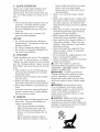 4
4
-
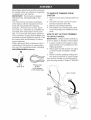 5
5
-
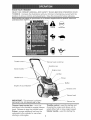 6
6
-
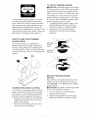 7
7
-
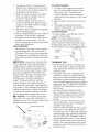 8
8
-
 9
9
-
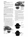 10
10
-
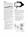 11
11
-
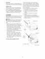 12
12
-
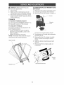 13
13
-
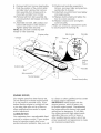 14
14
-
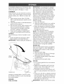 15
15
-
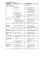 16
16
-
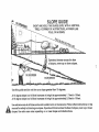 17
17
-
 18
18
-
 19
19
-
 20
20
-
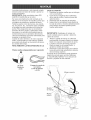 21
21
-
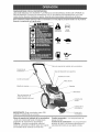 22
22
-
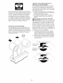 23
23
-
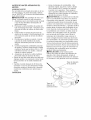 24
24
-
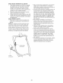 25
25
-
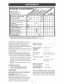 26
26
-
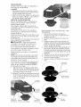 27
27
-
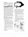 28
28
-
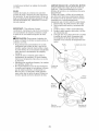 29
29
-
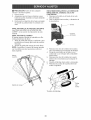 30
30
-
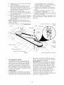 31
31
-
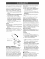 32
32
-
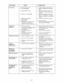 33
33
-
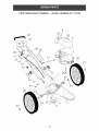 34
34
-
 35
35
-
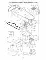 36
36
-
 37
37
-
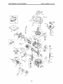 38
38
-
 39
39
-
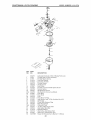 40
40
-
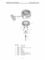 41
41
-
 42
42
-
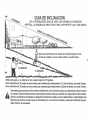 43
43
-
 44
44


Craftsman 917.773752 El manual del propietario
- Categoría
- Herramientas de jardín
- Tipo
- El manual del propietario
- Este manual también es adecuado para
En otros idiomas
- English: Craftsman 917.773752 Owner's manual
Documentos relacionados
-
Craftsman 917.773754 El manual del propietario
-
-
-
-
-
-
-
-