
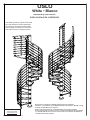
OSLO
White • Blanco
Assembly instruction
Instrucciones de instalación
R1-99934 / 2011-08-04
OSLO
White • Blanco
R1-99934 / 2011-09-12 / Rev. 2012-02-22
Review these instructions completely before beginning installation.
Questions - call customer service 855-DOLLE US or 763-746-7830 - Monday - Friday
8:00-5:00 central. Metric tools required.
Revise estas instrucciones en su totalidad antes de iniciar la instalación.
Si tiene alguna pregunta, llame al servicio al cliente al 855-DOLLE desde los EE.UU
o al 763-746-7830 de lunes a viernes de 8:00 a 5:00, hora central de los EE.UU. Se
necesitan herramientas métricas.
Mounting videos:
Vídeos de montaje:
www.dolleusa.com
Local building codes vary. Please consult with
your local ofcials for specic requirements.
Las normas de construcción locales pueden
variar. Póngase en contacto con los técnicos
locales para conocer los requisitos locales.

2
× 11
K1-32031
Ø47"
Ø120cm
K1-32061
Ø55" Ø140cm
K1-32066
Ø63" Ø160cm
× 1
K1-32030
Ø47" Ø120cm
K1-32060
Ø55" Ø140cm
K1-32065
Ø63" Ø160cm
35 7/16"
900mm
× 1
K2-32001
35 7/16"
900mm
× 1
K1-32002
35 7/16"
900mm
× 1
K1-32001
13/16"
20mm
46 1/16"
1170mm
× 1
K3-07013
43 5/16"
1100mm
1"
25mm
× 1
K1-32023
38"
965mm
1"
25mm
× 3
K1-32029
45 1/4"
1150mm
1"
25mm
× 11
K1-32028
× 26
K1-32015
× 60
K1-32012
× 24
K1-32011
2 3/16"
56mm
× 2
K1-32004
× 1
K1-32014
1 1/4"
32mm
× 1
K1-32024
6 1/8"
155mm
× 1
K1-32013
6 5/16"
160mm
× 11
K1-32010
2 3/16"
56mm
× 1
K1-32005
× 1
K1-32006
× 1
K1-32019
× 15
K1-32026
× 15
K1-32025
× 120
K1-32075
8 ×
K1-32072
3'-3 3/8" = 1 m
1 9/16"
40mm
Ø47" Ø120cm:
K2-32501
14'-9" = 4.5 m
39 1/2"
1003mm
× 1
K2-32018
9/16"
15mm
× 4
K2-32042
× 3
K1-32045
5 ×
K1-32071
23'-7 1/2" = 7.2 m
Ø55" Ø140cm:
K2-32502
16'-5" = 5.0 m
Ø63" Ø160cm:
K2-32503
18'-0 1/2" = 5.5 m
R1-99934-001
1
4
2
5 6
3
7 8 9
10 11
12 13 14 15 16 17 18 19
20 21 22 23 24 25
28 29
26
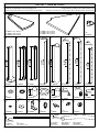
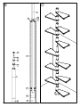
Part list • Parte de la lista
Components & Number of Each Component
Please check that all items are included before assembly
Componentes y Número de cada componente
Verique que todos los componentes estén incluidos antes de la entrega

3
× 1
K2-32085
× 1
K1-32080
Ø47" Ø120cm
K1-32081
Ø55" Ø140cm
K2-32082
Ø63" Ø160cm
× 32
K1-32070
1 9/16"
40mm
39 3/8"
1000mm
× 1
K2-32520
× 26
K3-03031
M6×10×20mm
× 8
K3-08004
Ø10×70mm
× 2
K3-03024
M20mm
× 2
K3-04020
Ø20mm
× 1
K3-08002
Ø8x40
× 4
R1-63616
Ø10mm
× 14
K1-32097
× 26
K1-32096
× 1
K1-32046
× 1
K3-90001
Torx 25
Torx 30
PH2
3mm
13mm
30mm
4 mm
2.5mm
× 5
K1-01015
× 120
K3-10200
M6×5mm
× 92
K3-10100
Ø6×40mm
× 8
K3-10075
Ø8mm
× 8
K3-10175
Ø8×70mm
× 120
K3-10250
M6×16mm
× 30
K3-10125
Ø5×35mm
× 15
K3-10025
M5mm
× 15
K3-10000
M5×18mm
× 27
K3-05013
M6×6mm
R1-99934-001
30
33 34 35
50 5251 53 54 55 56 57
58 59 60 61 62 63
39 40 41 4238
64
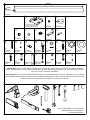
IMPORTANT: DO NOT USE PARTS OTHER THAN THOSE INCLUDED WITH THE PRODUCT. REPLACEMENT
PARTS PURCHASED LOCALLY MUST BE METRIC. IN CASE PARTS HAVE BEEN LOST OR DAMAGED CONTACT
DOLLE USA INC. FOR REPLACEMENT.
IMPORTANTE: NO UTILICE PIEZAS DIFERENTES DE LAS SUMINISTRADAS CON EL PRODUCTO. LAS PIEZAS
DE RECAMBIO ADQUIRIDAS POR SEPARADO DEBEN SER MÉTRICAS. EN CASO DE PÉRDIDA DE PIEZAS O DE
PIEZAS DAÑADAS, PÓNGASE EN CONTACTO CON DOLLE USA INC.
TOOLS REQUIRED - NOT SUPPLIED
HERRAMIENTAS NECESARIAS
- NO SUMINISTRADAS

4
8 1/4"
210mm
8 7/16"
215mm
8 11/16"
220mm
8 7/8"
225mm
9 1/16"
230mm
9 1/4"
235mm
3/16"
5mm
4
12
14
13
15
× 1
× 2
× 3
× 4
× 5
R1-99934-003
8 1/4"
210mm
8 7/16"
215mm
8 11/16"
220mm
8 7/8"
225mm
9 1/16"
230mm
9 1/4"
235mm
Spacers for oor section
Separadores de sección del piso

5
8 1/4"
210mm
8 7/16"
215mm
8 11/16"
220mm
8 7/8"
225mm
9 1/16"
230mm
9 1/4"
235mm
×3
×4
3/16"
5mm
16
13
13
12
1
×1
×2
×5
R1-99934-004
8 1/4"
210mm
8 7/16"
215mm
8 11/16"
220mm
8 7/8"
225mm
9 1/16"
230mm
9 1/4"
235mm
Spacers for treads
Separadores para peldaños

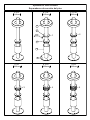
6
To determinate the number of spacers to use based on your staricase height:
Figure on page 7:
Before installing, calculate the exact height at your stairs by measuring the distance from •
the upstair stairs oor to the downstairs oor vertically along the wall – see (H)
To determine the number of spacer rings required table and nd staircase height (H). •
Example – 107 5/16” staircase height requires 3 rings on 12 treads and 1 extra ring on 5
treads.
Only rst tread has spacer rings on both top and bottom. All other treads, the spacer •
rings t on top at tread only.
Para determinar el número de separadores a utilizar en su altura de escalera:
Figura en la página 7:
Antes de la instalación, calcule la altura exacta en sus escaleras midiendo la distancia •
desde el piso de arriba hasta el piso de abajo a lo largo de la pared; véase la gura (H)
Para determinar el número de anillos de escalera necesarios, consulte la altura de la •
escalera en la tabla (H). Por ejemplo - una altura de escalera de 107 5/16” requiere 3
anillos en 12 peldaños y 1 anillo adicional en 5 peldaños.
Únicamente el primer peldaño tiene anillos separadores arriba y abajo. En los demás •
peldaños, los anillos separadores sólo se montan en la parte superior del peldaño.

7
107 5/16"
2725mm
H
N
12
12
N
12
N
12
N
12
N
12
N
12
N
12
N
12
N
12
N
12
N
Total
N×T
P
12
3 rings per treads × 12 = 36 rings
1 extra ring per treads × 5 = 5 rings
107 5/16"
2725mm
12 treads
12
N
T
12
rings
N
12
extra rings
P
107 5/16"
2725mm
R1-99934-005
First step is only step rings
on top and bottom. Remain-
ing steps only on top.
En el primer peldaño hay
anillos en la parte superior
e inferior.
En los demás peldaños,
sólo hay anillos en la parte
superior.
extra rings
anillos adicionales
rings
anillos
3 rings per tread × 12 = 36 rings
3 anillos por peldaño = 36 anillos
1 extra ring per tread × 5 = 5 rings
1 anillo adicional por peldaño x 5 = 5 anillos
12 treads
12 peldaños
Treads
7
107 5/16"
2725mm
H
N
12
12
N
12
N
12
N
12
N
12
N
12
N
12
N
12
N
12
N
12
N
Total
N×T
P
12
3 rings per treads × 12 = 36 rings
1 extra ring per treads × 5 = 5 rings
107 5/16"
2725mm
12 treads
12
N
T
12
rings
N
12
extra rings
P
107 5/16"
2725mm
R1-99934-005
First step is only step rings
on top and bottom. Remain-
ing steps only on top.
En el primer peldaño hay
anillos en la parte superior
e inferior.
En los demás peldaños,
sólo hay anillos en la parte
superior.
extra rings
anillos adicionales
rings
anillos
3 rings per tread × 12 = 36 rings
3 anillos por peldaño = 36 anillos
1 extra ring per tread × 5 = 5 rings
1 anillo adicional por peldaño x 5 = 5 anillos
12 treads
12 peldaños
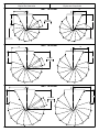
The rst step gets the
amount on N-rings on
both top and bottom.
The remaining steps get
the amount of N-rings
only on top.
El primer paso consigue la
cantidad en N-ANILLOS en
ambas parte superior y el
fondo. Los pasos restantes
consiguen la cantidad de
N-ANILLOS sólo en parte
superior.
N
IMPORTANT: This is a sample diagram.
To nd out how many N and P rings your staircase will
require — refer to the chart on page 8.
IMPORTANTE: Este es un ejemplo de diagrama.
Para averiguar cuántos N y P anillos su escalera
requerirá - consulte la tabla de la página 8.
7
107 5/16"
2725mm
H
N
12
12
N
12
N
12
N
12
N
12
N
12
N
12
N
12
N
12
N
12
N
Total
N×T
P
12
3 rings per treads × 12 = 36 rings
1 extra ring per treads × 5 = 5 rings
107 5/16"
2725mm
12 treads
12
N
T
12
rings
N
12
extra rings
P
107 5/16"
2725mm
R1-99934-005
First step is only step rings
on top and bottom. Remain-
ing steps only on top.
En el primer peldaño hay
anillos en la parte superior
e inferior.
En los demás peldaños,
sólo hay anillos en la parte
superior.
extra rings
anillos adicionales
rings
anillos
3 rings per tread × 12 = 36 rings
3 anillos por peldaño = 36 anillos
1 extra ring per tread × 5 = 5 rings
1 anillo adicional por peldaño x 5 = 5 anillos
12 treads
12 peldaños
Extra spacer P-rings are
placed on top of N-ings,
evenly distributed through-
out the staircase until
required amount are used.
See chart on page 8 for
number required.
Los P-ANILLOS extra del
espaciador son colocados
encima de N-ings, uni-
formemente distribuido a
través de la escalera hasta
que cantidad necesaria sea
utilizada. Vea gráco en
la página 8 para número
necesario.
P

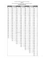
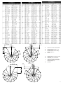
8
R1-99934-005
Number of spacer rings based on stair height
inches
Número de anillos separadores según la altura de la escalera
pulgadas

9
R1-99934-005
Number of spacer rings based on stair height
metric
Número de anillos separadores según la altura de la escalera
unidades métricas

10
25 9/16"
650mm
A
A
B B
V
+
–
+
–
+
–
29 1/2"
750mm
A A
B B
V
–
+
33 7/16"
850mm
A A
B B
V
+
–
–
+
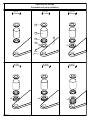
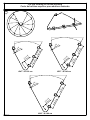
R1-99934-007
Ø47" Ø120cm
Ø55" Ø140cm
Ø63" Ø160cm
Right spiral
Espiral de la derecha
Left spiral
Espiral de la izquierda
First baluster
Primer balaustre
First baluster
Primer balaustre

11
29 1/2"
750mm
A A
B B
V
-
+
+
-
33 7/16"
850mm
A A
B B
V
-
+
+
-
V
B > 0
A
+
–
25 9/16"
650mm
A
A
B B
V
+
-
-
+
A
V
B < 0
–
+
A
B < 0
–
+
R1-99934-007
A distancia desde la pared al primer
balaustre
B centro del poste al balaustre -
distancia a lo largo de la pared
V oricio de plantilla para taladrar el
balaustre (gura 1)
N peldaños
A distance from wall to rst baluster
B center of post to baluster – dis-
tance along wall
V template hole to use for drilling
baluster (gure 1)
N treads
29 1/2"
750mm
A A
B B
V
-
+
+
-
33 7/16"
850mm
A A
B B
V
-
+
+
-
V
B > 0
A
+
–
25 9/16"
650mm
A
A
B B
V
+
-
-
+
A
V
B < 0
–
+
A
B < 0
–
+
R1-99934-007
B > 0

12
½V
½V
1
1
3
50
51
52
50
1
3
50
5152
3
1
1
1
R1-99934-010
1
3
4
2
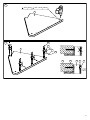
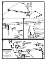
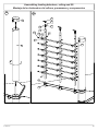
Assembling baluster supports to stairs
Montaje de los soportes del balaustre a las escaleras
We recommend the
leading edge of treads be
the long edge of laminated
beech, rather than the end
grain edge. This example
shows how to place supports
for a clockwise staircase.
Recomendamos el borde
de ataque de bandas de ro-
dadura ser el borde largo del
laminado abedul, en lugar de
al nal grano borde. En este
ejemplo se muestra cómo
colocar soportes para una
escalera de las agujas del
reloj.
End grain
(back of tread)
Fin grano
(parte posterior
de la banda de
rodadura)
Leading edge
(long grain)
borde delantero (grano largo)

13
2 15/16"
75mm
12 3/8"
315mm
12 3/8"
315mm
13/16"
20mm
C =
25 9/16"
650mm
Ø47" / Ø 120 cm
2
3
2
3
13 3/4"
350mm
13 3/4"
350mm
3 5/8"
92mm
C =
29 1/2"
750mm
13/16"
20mm
Ø55" / Ø 140 cm
15 3/4"
400mm
15 3/4"
400mm
3 5/8"
92mm
C =
33 7/16"
850mm
13/16"
20mm
Ø63" / Ø 160 cm
R1-99934-015
5

14
9 15/18"
250mm
9 15/18"
250mm
2 17/18"
75mm
7/9"
20mm
Ø47" / Ø 120 cm
11 4/9"
290mm
11 4/9"
290mm
3 11/18"
92mm
7/9"
20mm
Ø55" / Ø 140 cm
13"
330mm
13"
330mm
3 11/18"
92mm
7/9"
20mm
Ø63" / Ø 160 cm
R1-99934-016
5R
Cut top landing for round opening
Corte del rellano superior para abertura redonda

15
2
3
50
50
51
52
3/16"
4mm
max 1 3/16"
30mm
2
50
2
3
52 51
R1-99934-020
6
7

16
2 3/4"
70mm
15
13
14
12
0 - 5
pcs | piezas
C
R
3 3/8"
85mm
1/4"
7mm
4
Ø 1/4" [Ø 6mm]
2 3/4" [70mm]
Ø 3/8" [Ø 10mm]
2 3/4" [70mm]
4
4
55
54
53
R1-99934-025
8
9
10
11
12
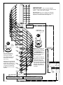
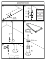
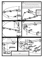
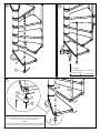
Assembling stair case
Montaje de la escalera
Wood | Madera:
Concrete | Hormigón:
NOTE
Installers responsibil-
ity to ensure adequate
backing material is in
place. Anchor sleeves
(53) for concrete only.
NOTA
Los instaladores deben
asegurarse de garan-
tizar el montaje de un
soporte adecuado. Sólo
vainas de anclaje (53)
para hormigón.

17
75 9/16"
1920mm
12
13
16
13
1
2
4
5
18
1
2
3
6
19
18
5
5
18
4
6
19
18
5
H
71 1/4"
1810mm
3 9/16"
90mm
X
[ 250 mm ]
Min.
10"
4
5
6
X =
H -
75 9/16"
1920mm
X
6
R1-99934-030
13
15 16
14
17
Floor
Suelo

18
7
56
20
6
5
57
7
56
20
6
19
18
5
57
R1-99934-035
18
19

19
56
21
57
22
22
53
50
54
55
38
Ø 1/4" [Ø 6mm]
2 3/4" [70mm]
Ø 3/8" [Ø 10mm]
2 3/4" [70mm]
Ø 3/16" [Ø 4mm]
max 1 3/16" [30mm]
R1-99934-040
20
23
21
22
NOTE
Installers responsibility to en-
sure adequate backing material
is in place. Anchor sleeves (53)
for concrete only.
NOTA
Los instaladores deben aseg-
urarse de garantizar el montaje
de un soporte adecuado. Sólo
vainas de anclaje (53) para
hormigón.
Wood | Madera:
Concrete | Hormigón:

20
56
57
21
22
22
53
54 55
50
38
Ø 3/16" [Ø 4mm]
max 1 3/16" [30mm]
Ø 1/4" [Ø 6mm]
2 3/4" [70mm]
Ø 3/8" [Ø 10mm]
2 3/4" [70mm]
R1-99934-041
20R
a
21R
23R
20R
b
22R
20R
c
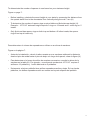
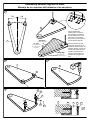
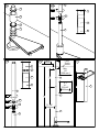
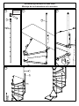
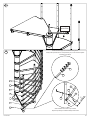
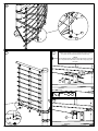
THIS FIGURE SHOWS TRACING OPENING EDGE
If the landing is to t into a round hole, it will have to be cut. Measure the
distance from the center pole and the center point of the wall where the
opstairs landing will be attached. Using a string and pencil, mark the this
distance in an arch where to cut the landing. Cut using a variable saw
with a ne tooth blade. Sand smooth with ne grit sand paper.
ESTA ILUSTRACIÓN MUESTRA EL BORDE DE LA ABERTURA DE TRAZADO
El rellano deberá cortarse si se monta en un agujero redondo. Mida la distancia
desde el poste central y el punto central de la pared donde se jará el rellano supe-
rior. Con una cuerda y un lápiz, marque la distancia en un arco por donde se cortará
el rellano. Corte con una sierra variable provista de una hoja de dientes pequeños.
Lije el acabado con papel de lija de grano no.
TIP
Tape cut line to help
prevent chipping
CONSEJO
Sujete la línea de
corte para evitar
roturas.
NOTE
Installers responsibility to ensure adequate backing material is in
place. Anchor sleeves (53) for concrete only.
NOTA
Los instaladores deben asegurarse de garantizar el montaje de
un soporte adecuado. Sólo vainas de anclaje (53) para hormigón.
Wood | Madera:
Concrete | Hormigón:

21
10
23
10
9
2
4
3
1
R1-99934-050
24 25 26
27
Assembling balusters to stair case
Montaje de los balaustres en la escalera
CAUTION
PRECAUCIÓN

22
9
17
23
Ø 3/16" [Ø 4mm] max 1 9/16" [40mm]
Ø 5/16" [Ø 8mm]
max 1 9/16" [40mm]
5/16"
8mm
1 9/16"
40mm
3/16"
4mm
8
9
50
51
17
58
R1-99934-055
28 29
30
Wood | Madera:
Concrete | Hormigón:
NOTE
Installers responsibility to ensure adequate backing material is
in place. Anchor sleeves (58) for concrete only.
NOTA
Los instaladores deben asegurarse de garantizar el montaje de
un soporte adecuado. Sólo vainas de anclaje (58) para hormigón.

23
1
2
3
4
5
6
7
2"
50mm
59
25
28
34
64
28
25
R1-99934-060
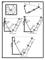
31
32
Start at bottom and work to top of stairs
Empiece por abajo e instale de abajo hacia arriba
Slide ll xtures (25) with set screw facing down
Coloque las jaciones de los componentes (25) con el tornillo de ajuste
orientado hacia abajo
Pull tight
Aprete fuerte

24
3 1/8"
29
[80 mm]
3 1/8"
61
29
26
60
26
60
[80 mm]
3 1/8"
29
26
26
60
60
42
42
R1-99934-065
33 34
35
36
33 36
-
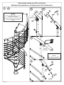
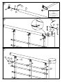
Assembling railing and ll to balusters
Montaje del pasamanos y componentes en los balaustres
i
Please handle very carefully – easy to
scratch when mounting
Por favor, manipular con mucho cuidado
– puede rayarse fácilmente durante el
montaje.
29
TIP
Tape cut line for smoother nish
CONSEJO
Sujete la línea de corte para obtener
un acabado más homogéneo

25
8
1
2
3
4
5
6
7
25
28
2"
50mm
59
28
25
34
69
R1-99934-070
37
Start at bottom and work to top of stairs
Empiece por abajo e instale de abajo hacia arriba
Slide ll xtures (25) with set screw facing down.
Coloque las jaciones de los componentes (25) con
el tornillo de ajuste orientado hacia abajo

26
8
35
24
23
63
62
11
25
34
28
52
51
59
34
64
R1-99934-075
38
39
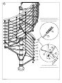
Assembling landing balusters, railing and ll
Montaje de los balaustres del rellano, pasamanos y componentes

27
30
60
26
60
26
61
60
26
60
26
34
28
59
34
25
64
42
42
R1-99934-080
40
41
42
TIP
Tape cut line for smoother
nish
CONSEJO
Sujete la línea de corte para
obtener un acabado más
homogéneo

28
40
39
39
40
39
41 58
55
54
38
61
21 22
R1-99934-085
43
44 45
46
NOTE
Installers responsibility to ensure adequate backing material
is in place. Anchor sleeves (58) for concrete only.
NOTA
Los instaladores deben asegurarse de garantizar el montaje
de un soporte adecuado. Sólo vainas de anclaje (58) para
hormigón.
-
 1
1
-
 2
2
-
 3
3
-
 4
4
-
 5
5
-
 6
6
-
 7
7
-
 8
8
-
 9
9
-
 10
10
-
 11
11
-
 12
12
-
 13
13
-
 14
14
-
 15
15
-
 16
16
-
 17
17
-
 18
18
-
 19
19
-
 20
20
-
 21
21
-
 22
22
-
 23
23
-
 24
24
-
 25
25
-
 26
26
-
 27
27
-
 28
28


Dolle 67312-2 Guía de instalación
- Categoría
- Conectores de cable
- Tipo
- Guía de instalación
Documentos relacionados
-
Dolle 67416-4 Guía de instalación
-
-
-
-
-
-
-
-
-