HK Audio BIG BASE SINGLE Manual de usuario
- Categoría
- Altavoces de la barra de sonido
- Tipo
- Manual de usuario
Este manual también es adecuado para

Manual 2.1
E 110 Sub A
E 110 Sub AS
E 210 Sub AS
E 435 / E 835
E 110 Sub
L Sub 1200
EA 600
• English
• Deutsch
• Français
• Italiano
• Español

Elements 2.1
2
E 110 Sub A
Powered Subwoofer
Mains
Green = On
Red = Limit/Error
Power
Made in Germany
Caution: To reduce the risk of
electric shock, grounding of
the center pin of this plug
must be maintained.
Caution: Risk of electric shock!
Do not open! Refer servicing to
qualified service personnel.
2
1
21
Sensitivity
+4 dB
-10 dB
Input
Through
Leave enough space for proper ventilation!
Min. imp. 8 Ohms
300 Watts
Speaker Out
Serial No.
1
2
4
5
7
6
8
9
Caution: Risk of electric shock!
Do not open! Refer servicing to
qualified service personnel.
Sensitivity
Mains
Power
Speaker
Out
Through
Input
Green = On
Red = Limit/Error
+4 dB
-10 dB
EA 600
Power Amp
Caution: To reduce the risk of
electric shock, grounding of the
center pin of the AC plug must
be maintained.
2
1
21
Min. imp.
4 Ohms
600 Watts
Made in Germany
Mid/High
Filter
Select the
number of
mid/high units
in ONE column
1
2
3
4
On
Off
Serial No.
1
2
4
5
6
7
8
9
Caution: To reduce the risk of
electric shock, grounding of the
center pin of this plug must be
maintained.
220-240 V~ 50-60 Hz
6 A rated current
Caution: Risk of electric shock! Do not open!
Refer servicing to qualified service personnel.
E 110 Sub AS
System Subwoofer
Made in Germany
Bass Gain
Through
Power
Input
Mid/High Filter
Leave enough space for proper ventilation!
Green = On
–12 dB +6 dB
Mains
Limit
Sub
Limit
Mid/High
Select the number of mid/high units in ONE column
2x E 435 = 1x E 835
Mid/High Out
E 435 / E 835
1+/1–
1 2 3 41
2
3
4
Sub Out
E 110 Sub
1+/1–
220-240 V~ 50-60 Hz
6 A rated current
Auto
Stand-by
off
on
Sens.
(dBu)
–10
+4
1
7
7
2 345
8
10
9 6

Elements 2.1
3
1
3
4
5
6
8
9
7 7
1 Mid/High-Filter
2 Sensitivity
3 Bass Gain
4 Input
5 Through
6 Limiter-Status LED
7 Speaker Out / Sub Out /
Mid/High Out
8 Mains Input
9 Power
10 Auto Stand-by

Version 2.3 05/2013
Important Safety Instructions! Read before
connecting!
This product has been built by the manufacturer in accordance
with IEC 60065 and left the factory in safe working order. To
maintain this condition and ensure non-risk operation, the user
must follow the advice and warning comments found in the
operating instructions. If this product shall be used in vehicles,
ships or aircraft or at altitudes exceeding 2000 m above sea
level, take care of the relevant safety regulations which may
exceed the IEC 60065 requirements.
WARNING: To prevent the risk of fire and shock hazard, do not
expose this appliance to moisture or rain. Do not open case – no
user serviceable parts inside. Refer service to qualified service
personnel.
This symbol, wherever it appears, alerts you to the
presence of uninsulated dangerous voltage inside the enclosure –
voltage that may be sufficient to constitute a risk of shock.
This symbol, wherever it appears, alerts you to the
presence of externally accessible hazardous voltage. External
wiring connected to any terminal marked with this symbol must
be a “ready made cable” complying with the manufacturers
recommendations, or must be a wiring installed by instructed
persons only.
This symbol, wherever it appears, alerts you to important
operating and maintenance instructions in the accompanying
literature. Read the manual.
This symbol, wherever it appears, tells you: Take care!
Hot surface! To prevent burns you must not touch.
• Read these instructions.
• Keep these instructions.
• Follow all warnings and instructions marked on the product and
in this manual.
• Do not use this product near water. Do not place the product
near water, baths, wash basins, kitchen sinks, wet areas,
swimming pools or damp rooms.
• Do not place objects containing liquid on the product – vases,
glasses, bottles etc.
• Clean only with dry cloth.
• Do not remove any covers or sections of the housing.
• The set operating voltage of the product must match the local
mains supply voltage. If you are not sure of the type of power
available consult your dealer or local power company.
• To reduce the risk of electrical shock, the grounding of this
product must be maintained. Use only the power supply cord
provided with this product, and maintain the function of the
center (grounding) pin of the mains connection at any time.
Make sure the mains outlet used provides a proper protective
ground connection.
• Protect the power cord from being walked on or pinched
particularly at plugs, convenience receptacles, and the point
where they exit from the device! Power supply cords should
always be handled carefully. Periodically check cords for cuts
or sign of stress, especially at the plug and the point where the
cord exits the device.
• Never use a damaged power cord.
• Unplug this product during lightning storms or when unused for
long periods of time.
• This product can be fully disconnected from mains only by
pulling the mains plug at the unit or the wall socket. The
product must be placed in such a way at any time, that
disconnecting from mains is easily possible.
• Fuses: Replace with IEC127 (5x20mm) type and rated fuse for
best performance only! It is prohibited to use “patched fuses”
or to short the fuse-holder. Replacing any kind of fuses must
only be carried out by qualified service personal.
• Refer all servicing to qualified service personnel. Servicing is
required when the unit has been damaged in any way, such as:
- When the power cord or plug is damaged or frayed.
- If liquid has been spilled or objects have fallen into the product.
- If the product has been exposed to rain or moisture.
- If the product does not operate normally when the operating
instructions are followed.
- If the product has been dropped or the cabinet has been
damaged.
• Do not connect external speakers to this product with an
impedance lower than the rated impedance given on the
product or in this manual. Use only cables with sufficient cross
section according to the local safety regulations.
• Keep away from direct sunlight.
• Do not install near heat sources such as radiators, heat
registers, stoves or other devices that produce heat.
• Do not block any ventilation openings. Install in accordance
with manufacturer’s instructions. This product must not be
placed in a built-in installation such as a rack unless proper
ventilation is provided.
• Always allow a cold device to warm up to ambient temperature,
when being moved into a room. Condensation can form inside it
and damage the product, when being used without warming up.
• Do not place naked flame sources, such as lighted candles on
the product.
• The device must be positioned at least 20 cm/8“ away from
walls.
• Use only with the cart, stand, tripod, bracket or table specified
by the manufacturer or sold with the product. When a cart is
used, use caution when moving the cart/product combination to
avoid injury from tip-over.
• Use only accessories recommended by the manufacturer, this
applies for all kind of accessories, for example protective
covers, transport bags, stands, wall or ceiling mounting
equipment. In case of attaching any kind of accessories to the
product, always follow the instructions for use, provided by the
manufacturer. Never use fixing points on the product other than
specified by the manufacturer.
• This appliance is NOT suitable to be used by any person or
persons (including children) with limited physical, sensorical or
mental ability, or by persons with insufficient experience and/
or knowledge to operate such an appliance. Children under
4 years of age must be kept away from this appliance at all
times.
• Never push objects of any kind into this product through
cabinet slots as they may touch dangerous voltage points or
short out parts that could result in risk of fire or electric shock.
• This product is capable of delivering sound pressure levels
in excess of 90 dB, which may cause permanent hearing
damage! Exposure to extremely high noise levels may cause a
permanent hearing loss. Wear hearing protection if continously
exposed to such high levels.
• The manufacturer only guarantees the safety, reliability and
efficiency of this product if:
- Assembly, extension, re-adjustment, modifications or repairs
are carried out by the manufacturer or by persons authorized
to do so.
- The electrical installation of the relevant area complies with the
requirements of IEC (ANSI) specifications.
- The unit is used in accordance with the operating instructions.
• This product is optimized for use with music and speech
signals. Using this product with sine wave, square wave or
other kind of measuring signals at higher level may lead to
severe damage of the product.
General Notes on Safety for Loudspeaker
Systems
Mounting systems may only be used for those loudspeaker
systems authorized by the manufacturer and only with the
mounting accessories specified by the manufacturer in the
installation instructions. Read and heed the manufacturer’s
installation instructions. The indicated load-bearing capacity
cannot be guaranteed and the manufacturer will not be liable for
damages in the event of improper installation or the use of
unauthorized mounting accessories.
The system’s load-bearing capacity cannot be guaranteed and
the manufacturer will not be liable for damages in the event
that loudspeakers, mounting accessories, and connecting and
attaching components are modified in any way.
Components affecting safety may only be repaired by the
manufacturer or authorized agents, otherwise the operating
permit will be voided.
Installation may be performed qualified personnel only, and
then only at pick-points with sufficient load-carrying capacity and
in compliance with local building regulations. Use only the
mounting hardware specified by the manufacturer in the
installation instructions (screws, anchors, etc.). Take all the
precautions necessary to ensure bolted connections and other
threaded locking devices will not loosen.
Fixed and portable installations (in this case, speakers and
mounting accessories) must be secured by two independent
safeties to prevent them from falling. Safeties must be able to
catch accessories or parts that are loose or may become loose.
Ensure compliance with the given national regulations when
using connecting, attaching, and rigging devices. Factor potential
dynamic forces (jerk) into the equation when determining the
proper size and load-bearing capacity of safeties.
Be sure to observe speaker stands’ maximum load-bearing
capacity. Note that for reasons of design and construction, most
speaker stands are approved to bear centric loads only; that is,
the speakers’ mass has to be precisely centered and balanced.
Ensure speaker stands are set up stably and securely. Take
appropriate added measures to secure speaker stands, for
example when:
- the floor or ground surface does not provide a stable, secure
base.
- they are extended to heights that impede stability.
- high wind pressure may be expected.
- there is the risk that they may be knocked over by people.
Special measures may become necessary as precautions against
unsafe audience behavior. Do not set up speaker stands in
evacuation routes and emergency exits. Ensure corridors are
wide enough and put proper barriers and markings in place
when setting speaker stands up in passageways. Mounting and
dismounting are especially hazardous tasks. Use aids suitable
for this purpose. Observe the given national regulations when
doing so.
Wear proper protection (in particular, a helmet, gloves, and
safety shoes) and use only suitable means of ascent (ladders,
scaffolds, etc.) during installation. Compliance with this
requirement is the sole responsibility of the company performing
the installation.
WARNING!
After installation, inspect the system comprised of the mounting
fixtures and loudspeakers to ensure it is properly secured.
The operator of loudspeaker systems (fixed or portable) must
regularly inspect or task a third party to regularly inspect all
system components in accordance with the given country’s
regulations and have possible defects repaired immediately.
We also strongly recommend maintaining a logbook or the like to
document all inspections.
When installing speakers for longer lasting or permanent outdoor
operation, be sure to take into account the stability and load-
bearing capacity of platforms and surfaces; loads and forces
exerted by wind, snow, and ice; as well as thermal influences.
Also be sure to provide sufficient safety margins for the rigging
points used for flown systems. Observe the given national
regulations when doing so.
• Ask the manufacturer if your product is allowed for outdoor
usage !
Professional loudspeaker systems can produce harmful
volume levels. Even prolonged exposure to seemingly harmless
levels (starting at about 95 dBA SPL) can cause permanent
hearing damage! Therefore we recommend that everyone who is
exposed to high volume levels produced by loudspeaker systems
wears professional hearing protection (earplugs or earmuffs).
Manufacturer: Stamer Musikanlagen GmbH, Magdeburger Str. 8,
66606 St. Wendel, Germany

Elements 2.1
5
Welcome to the HK Audio family!
Thank you for choosing a brand-name product made by our company.
Rest assured, we engineered and built it with the greatest care so it will
serve you well for many tomorrows to come.
Even if your experience with sound systems runs deep, some things
about this product are sure to be new to you. This is why we ask that
you do not set this manual aside without reading it first. Be sure to keep
it in a safe place for later reference.
Here‘s wishing you the best sound at every occasion!
Your HK Audio team
Warranty
Register each ELEMENTS system component separately to extend
your warranty to five years free of charge! Use the convenient online
registration option at www.hkaudio.com.
If you are unable to register online, please fill out the enclosed warranty
card, ensuring all information is legible and complete, and mail or fax
it to us. The registration is only valid if the warranty registration card
is filled out and returned to HK AUDIO® or the device is registered via
Internet within 30 days of the date of purchase.
We are also interested in learning where and by whom our devices are
used. This information will help us design future products. Your data are
of course protected by German privacy laws.
Thank you!
HK AUDIO
Technischer Service
Postfach 1509
66959 St. Wendel, Germany
Fax: +49 6851 905 100
• English • Deutsch • Français • Italiano • Español

Elements 2.1
6
1 The ELEMENTS principle
All ELEMENTS systems comprise active and passive components
as well as customized accessories. Active components include an
built-in amplifier with class D output stages, which power the passive
components. No additional amplifiers are required. For special
installation and voice applications, in which only passive loudspeakers
are used, a separate EA 600 amp element is available.
The interconnecting of passive components and the connection to
active components is cable-free for mid/high elements via E-connect,
while passive bass elements are connected with a conventional
Speakon NL4 cable. Active components are interconnected with an XLR
microphone cable.
This means ELEMENTS system components can be combined with
numerous different systems. The following diagram shows how many
passive elements can be powered by a single active component.
E 110 Sub AS
1x 10"
2x 600 W
active
E 110 Sub A
1x 10"
1x 600 W
EA 600
Amp
1x 600 W
2x
E 835
active
active
E 210 Sub AS
2x 10"
2x 1200 W
1x + 1x
E 835
or
1x
E 835
1xor
2x
E 835
1x+
3x
E 835
1x+
1x E 835 = 2x E 435
L Sub 1200
E 110 Sub
E 110 Sub
E 110 Sub
The following generally applies: You can reduce the number of passive
components connected to an active element to suit your needs. The
smallest ELEMENTS system accordingly consists of an E 110 Sub A
and a E 435 mid/high element. Alternatively, even just an EA 600 amp
element and an E 435 mid/high element for pure voice communication.
However, there is a limit to the number of passive components you
can connect to an active element, even if the active element provides
more power than required, depending on the combination! The key here
is not the power, but the total impedance of the passive components
connected to an active element. Since both E-connect and Speakon
are connected as parallel ports, the total impedance declines with each
additional passive element. If the impedance is too low, the electronics
of the active elements may be damaged due to overheating.
2 Assembly and connection of
elements
When assembling, please ensure the active system components are
switched off, otherwise there is a risk of damage! Set the bass gain
knob in the middle position with (0 dB / click center). Always start by
assembling the complete system together with cabling and only then
connect the active components. When disassembling: first switch off all
active system components.
Caution: Be careful to ensure that the voltage data shown on
the active components corresponds to the local mains voltage.
Connecting to excess mains voltage may destroy the electronic
equipment.
Bass elements
When using an individual bass element, always ensure it is placed on a
firm and level surface. Depending on the operating mode and system
configuration, E-connect allows bass elements to be installed on either
the short or long sides, while four rubber feet at the base ensure vertical
stability. When installing horizontally, one long side of the housing has
two runners, while the opposite housing side has appropriate grooves,
which allow multiple bass elements to be safely stacked on top of each
other.
When using more than one bass element, it is advisable to start with the
passive bass horizontally, and then stack the active bass on top, so that
it can power the mid/high element via E-connect.
Mid/high elements
E-connect facilitates the swift and secure signal connection of the
element, by establishing the electrical and mechanical connection to the
nearest mid/high element, bass, spacer stem, or the foot. The durable
bayonet system ensures a safe mechanical connection when installing
simply by clicking the components together and also transmits the
loudspeaker signal.
Connecting the elements
Push!
Position the components to be connected such that the respective tube
joints are over each other. To fix the individual components together
securely, insert the tube joint of the upper element completely into the
adjusting sleeve of the lower element. Be careful to ensure that the
release button snaps into the relevant adjusting hole.

Elements 2.1
7
Uncoupling a connection
Pull!
To disconnect components, press and hold the release button in the
tube joint and then pull apart the components.
The correct height
Since line-array systems such as ELEMENTS provide vertical sound
emission, when installing, always ensure that the central point of a line
of one or multiple mid/high elements is continually adjusted to the head
height of the listener.
To adapt the height of a line, infinitely adjustable spacer stems, which
can be locked using a twist-off cap, are optionally available in two
different lengths:
EP 1: 95 - 160 cm
EP 2: 40 - 60.5 cm
The correct angle
To achieve perfect emitting properties, all connected components must
emit sound at the same angle. The ELEMENTS locking wedge feature
lets you lock the mid/high element under each other or on a bass,
whereupon twisting is no longer possible.
Push!
The locking wedge is simply clicked into the special shaft provided and
released simply by applying slight pressure to the central plate.
Note: for older ELEMENTS system components without locking
wedges, retrofit kits are available - please connect your ELEMEMTS
dealer.
Installation pointers
When installing, always be careful to ensure a horizontal and firm
surface! To avoid any risk of overturning, the following installation
information for ELEMENTS configurations should be followed to the
letter.
Combinations with foot EF 45 connected to spacer stems
EP 1 / EP 2 and the mid/high element E 435 (or E 835)
Be careful when installing an ELEMENTS system with the foot EF 45 to
ensure the extended feet are always pushed out completely and fixed by
locking screws. The following specified maximum heights must not be
exceeded. Never connect together two spacer stems!
1x E 435
+ EP 1
max.
2,05 m/
8-1/16"
1x E 435
+ EP 1
max.
2,45 m/
9-5/8"
AMP
2x E 435
+ EP 2
max.
1,80 m/
7-5/64"
3x E 435
max.
1,69 m/
6-21/32"
AMP
AMP
Combinations with bass element E 110 Sub A / AS
connected to spacer stems EP 1 or EP 2 and the mid/high
element E 435 / E 835
The following specified maximum heights must not be exceeded. Never
connect together two spacer stems!
2x E 435
+ EP 1
max.
2,10 m/
8-17/64"
1x E 435
+ EP 1
max.
2,55 m/
10-25/64"
2x E 435
+ EP 2
max.
2,00 m/
7-7/8"
2x E 435
max.
1,06 m/
4-11/64"
AMP
AMP
Combinations with bass element E 210 Sub AS connected
to the spacer stem EP 2 and the mid/high element E 835
The following specified maximum heights must not be exceeded.
Never connect together two spacer stems! When operating three E 835
elements, it is important to ensure the bass is only used in a horizontal
position.
1x E 835
+ EP 1
max.
1,96 m/
7-23/32"
2x E 835
max.
2,17 m/
8-17/32"
3x E 835
max.
2,63 m/
10-23/64"
2x E 835
max.
1,60 m/
6-19/64"
• English • Deutsch • Français • Italiano • Español

Elements 2.1
8
Installation of the bass elements (E 110 Sub A / AS,
E 110 Sub, E 210 Sub AS, L Sub 1200)
When used individually, the bass element can be operated in either a
vertical and horizontal position. However, bass elements can only be
stacked in a horizontal position! No more than three bass elements
should be stacked horizontally on top of each other!
or /
oder
or /
oder
or /
oder
3 Control elements of the active
component
All active elements
provide similar
features – a diagram
of the control
elements is included
on page 2/3:
1 Mid/high fi lter with LED indicator
The mid/high filter is used to adjust the frequency response of the active
element electronics to the frequency response of the connected mid/
high element. This manual configuration is crucial, since the output
stage cannot automatically detect how many mid/high elements are
connected. However, when connecting a passive bass, no adaptation is
required.
Caution: The figures specified on the filter switch always apply to
the mid/high element E 435 (four tweeters). When using the mid/high
element E
835 (eight tweeters), this should always be counted as
two E
435s.
Example: mid/high filter of the E 210 Sub AS
2 Sensitivity switch (except E 210 Sub AS)
This switch allows you to adjust the sensitivity of the input stage
to the output level control of your mixer. When using a professional
mixer with symmetrical outputs, the adaptation should be set to
+4dB, which allows you to optimize use of the mixer faders and
avoid over-modulation. If a mixer with low output level control is used
(asymmetrical communication jack), select the –10 dB configuration.
The double-bass E 210 Sub AS does not include any adaptation switch,
since it is designed for professional applications with symmetrical
signals.
Important note: If the system includes multiple output stages (active
elements), for example in a stereo set-up, it is important to ensure
that the same sensitivity configuration is selected for all output
stages.
3 Bass Gain (only for E 110 Sub AS, E 210 Sub AS)
This knob adjusts the volume of the bass element but not the connected
mid/high elements. It can be configured within the range -12 to +6 dB,
and we recommend starting with the 0 dB setting.
4 Input
This combination socket can accommodate both XLR as well as jack
plugs. Connect symmetrical signals with an XLR microphone cable
or with stereo jack plugs to this socket. Asymmetrical signals can be
connected with a mono jack plug.
5 Through
Parallel XLR output to forward the input signal (input) to additional active
elements.
6 Limiter status LED
The two-color LED shows the status of the input signal.
Green = ready for operation
Red = Signal is over-amplified, whereupon the built-in RMS limiter is
triggered (to protect the electronics against over-amplification)
Caution: This device is not a clip LED. It is normal for the LED to
light up in red occasionally, since this simply shows that the RMS
limiter is operational. If the signal LED remains red during signal
peaks, check the output level control of the signal source and the
setting of the sensitivity switch.
The E 210 Sub AS includes a separate power LED, which lights up
green, if the power switch is set to ON and the power is turned on.
7 Speaker Out (E 110 Sub A, EA 600)
Sub Out / Mid/High Out (E 110 Sub AS, E 210 Sub AS)
The Speakon outputs on the E 110 Sub A and EA 600 are used to
connect the passive bass E 110 Sub and to forward signals to mid/high
elements via the optional accessory foot EF 45. For this purpose, use
the conventional Speakon NL4 cable (NL4 = four cores: 1+, 1-, 2+, 2-)
The basses with two output stages E 110 Sub AS and E 210 Sub AS
are equipped with separate outputs for passive basses and mid/high
elements. The Sub Out socket of the E 110 Sub AS can only be used
with the E 110 Sub, while the socket of the E 210 Sub AS may only be
used to connect a passive L Sub 1200.
Speakon cables are connected in a clockwise direction by pushing in
and turning the locking mechanism, turning counter-clockwise releases
the connection.
Caution: The mid/high output is parallel-connected to E-connect,
and may only be used when E-connect is not in operation.
Caution: If external devices are connected to the NL4 output, this
and the ELEMENTS components may be destroyed.

Elements 2.1
9
8 Mains Input
Connect this connector socket using a low-power connection cable
(included with delivery) with the mains socket.
Note: The active elements include a lockable V-Lock mains input
socket. Combined with a lockable connection cable ( „Volex“ or
structurally identical, optional available) the power cable can be cut
off thus preventing any risk of inadvertent reactivation.
9 Power switch
When switching on, the signal LED lights up for around 5 seconds in red
and then switches to green to indicate it is ready for operation. The fan
is temperature-controlled and runs throughout the system check.
10 Auto Stand-by (only E 110 Sub AS)
The E 110 Sub AS also includes an auto standby function, which is
switched on and off via an auto standby switch. When switched to ON,
the output stage will automatically revert to sleep mode if no signal
is connected for 180 minutes. From a level of -68 dB (1 kHz), the
E 110 Sub AS resumes operation. Auto standby to OFF deactivates this
function and the subwoofer remains permanently ON.
4 Accessories
EF 45 Base
The foot acts as the base for the top speakers, the amp module or
the spacer stem. The extendable base extensions ensure the attached
elements remain safely and securely in place.
• Stable foot with minimal footprint
• built-in E-connect-signal connection
• 2x parallel NL4 connection
• 7.7 kg
• available as option: The perfect bag for the EF 45
foot , which you can carry over your shoulder.
41 cm
36 cm
46 cm
41,5 cm
12,5 cm
EF 45 for transportation EF 45 in use
EP 1/EP 2 Speaker Poles
In confined spaces, these devices facilitate easy and swift installation.
They are infinitely variable and via E-connect, provide cable-free signal
feed for the attached top speakers.
• Anodized aluminum with large mounting screw
• Built-in E-connect-signal connection
• Weight EP 1: 0.8 kg; EP 2: 0.5 kg
min. 0,86 m
max. 1,52 m
0,94 m
EP 1
EP 2
min. 0,37 m
max. 0,54 m
0,45 m
Soft Bag (E 435, E 835, EA 600)
The padded case can accommodate four E 435 or two E 835 mid/high
elements or four EA 600 amp elements. In addition, a spacer stem can
also be fitted.
Subwoofer Cover
Subwoofers are frequently not moved around with kid gloves. With this
in mind, this cover was double-cushioned to effectively protect active
and passive subs against damage in transit.
Also available for ELEMENTS‘ permanent installation:
Install Kit E 435 • Install Kit E 435 A (active)
The ELEMENTS Install Kit consists of E 435 and EA 600
units that have been modified for wall mounting. Up to
six components may be combined. The elements can be
positioned horizontally through 180 degrees on the mounting
brackets and be fixed swiftly and hassle-free using the two
socket head screws provided.
Use speaker cords equipped with mono ¼" (6.3 mm) jack
plugs. Visit www.hkaudio.com to learn more about this.
• English • Deutsch • Français • Italiano • Español

Elements 2.1
10
5 Technical data
E 835 E 435 E 210 Sub AS E 110 Sub AS E 110 Sub A L Sub 1200 E 110 Sub EA 600
Power handling, nominal 300 W RMS @ 8 Ω 150 W RMS @ 16 Ω - 1200 W RMS @ 8 250 W RMS @ 10 Ω -
Continuous
power per amp
- - 1200 W Class-D @
4 Ω (Subs) / 1200
Watt Class-D @ 4
Ω (Mid/High)
600 W Class-D @
4 (Subs) / 600
Watt Class-D @ 4
(Mid/High)
600 W Class-D
@ 4 Ω
- - 600 W Class-D
@ 4 Ω
Frequency response
-10 dB
140 Hz – 20 kHz,
via active system
fi l t e r
140 Hz – 20 kHz,
via active system
fi l t e r
38 Hz – 150 Hzvia
active system
x-over
45 Hz – 150 Hz
via active system
x-over
45 Hz – 150 Hz
via active system
x-over
38 Hz - 150 Hz
via active system
x-over
45 Hz – 150 Hz
via active system
x-over
-
Nominal impedance 8 Ω 16 Ω 8 Ω 10 10 Ω 8 10 Ω -
Axial sensitivity 1 W
@ 1 m *
100 dB 97 dB------
Active protective
circuits
--RMS limiter,
subsonic fi lter;
DC, load, & thermal
(temp.- controlled
fan)
RMS limiter,
subsonic fi lter;
DC, load, & thermal
(temp.- controlled
fan)
RMS limiter,
subsonic fi lter;
DC, load, & thermal
(temp.- controlled
fan)
--RMS limiter,
subsonic fi lter;
DC, load, & thermal
(temp.- controlled
fan)
Input sensitivity - - +4 dBu (switchable) +4
dBu / -10 dBu
+4 dBu / -10 dBu
(switchable)
- - +4 dBu / -10 dBu
(switchable)
Connectors 1 x E-Connect In
1 x E-Connect Out
1 x E-Connect In
1 x E-Connect Out
1 x XLR-Combo In
1 x XLR-Through
2 x Speakon Out
(1 x Sub + 1 x
Mid-High)
2 x E-Connect Out
1 x XLR-Combo
In 1 x XLR-Through
2 x Speakon Out
(1 x Sub + 1 x
Mid-High)
2 x E-Connect Out
1 x XLR-Combo In
1 x XLR-Through
1 x Speakon
Parallel Out
2 x E-Connect Out
1 x Speakon In
1 x Speakon Out
1 x Speakon In
1 x Speakon Out
1 x E-Connect Out
1 x XLR-Combo In
1 x XLR-Through
1 x Speakon
Parallel Out
1 x E-Connect Out
Speakers 8 x 3.5" broadband 4 x 3.5" broadband - - - - -
Woofers - - 2 x 10"(2.,5" voice
coil)
1 x 10" (2" voice
coil)
1 x 10" (2" voice
coil)
2 x 10" (2.5" voice
coil)
1 x 10" (2" voice
coil)
-
Directivity 70° horizontal70° horizontal------
Corner frequency,
passive x-over
140 Hz, 12 dB/oct. 140 Hz, 12 dB/oct. - - - - - -
Pole mount - - 2 x E-Connect
coupler
2 x E-Connect
coupler
2 x E-Connect
coupler
2 x M20 1 x E-Connect
coupler
-
Optional accessories - - 100 mm Blue
Wheels
-----
Dimensions (W x H x D) 11 x 74.5 x 12 cm
(excl. E-Connect
sleeves)
11 x 38 x 12 cm
(excl. E-Connect
sleeves)
38 x 66,8 x 56 cm 30 x 48 x 46 cm 30 x 48 x 46 cm 38 x 66,8 x 56 cm 30 x 48 x 46 cm 11 x 38 x 12 cm
(excl. E-Connect
sleeves)
Weight 4.5 kg 2.35 kg 32 kg 18.5 kg 19 kg 29 kg 16.5 kg 2.75 kg

Elements 2.1
11
• English • Deutsch • Français • Italiano • Español

Version 2.3 08/2013 neu
Wichtige Sicherheitshinweise! Bitte vor
Anschluss lesen!
Dieses Produkt wurde gemäß IEC 60065 hergestellt und hat
das Werk in einem sicheren, betriebsfähigen Zustand verlassen.
Um diesen Zustand zu erhalten und um einen gefahrlosen
Betrieb zu gewährleisten, ist es notwendig, dass der Benutzer
die Empfehlungen und Warnhinweise befolgt, die in der
Betriebsanleitung zu finden sind. Bei Einsatz dieses Produktes
in Fahrzeugen, Schiffen oder Flugzeugen, oder in Höhen
oberhalb 2000 m Meereshöhe müssen die entsprechenden
Sicherheitsstandards zusätzlich zur IEC 60065 beachtet werden.
WARNUNG: Um das Risiko von Feuer oder Stromschlag zu
verhüten, darf dieses Gerät nicht Feuchtigkeit oder Regen
ausgesetzt werden. Öffnen Sie das Gehäuse nicht – im Inneren
gibt es keine Bauteile, die vom Benutzer wartbar sind. Die
Wartung darf nur von einem qualifiziertem Kundendienst
durchgeführt werden.
Dieses Symbol, wo immer es erscheint, warnt Sie vor
gefährlicher, nicht isolierter Spannung im Gehäuse – Spannung,
die möglicherweise genügt, eine Stromschlaggefahr darzustellen.
Dieses Symbol, wo immer es erscheint, warnt Sie vor
außen zugänglicher, gefährlicher Spannung. Eine Verbindung zu
jeder Anschlussklemme, die mit diesem Symbol versehen ist, darf
nur mit konfektioniertem Kabel hergestellt werden, dass den
Empfehlungen des Herstellers genügt, oder mit Kabel, das von
qualifiziertem Personal installiert wurde.
Dieses Symbol, wo immer es erscheint, macht Sie auf
wichtige Bedienungs- und Wartungsanweisungen aufmerksam,
die in beiliegenden Unterlagen zu finden sind. Bitte lesen Sie das
Handbuch.
Dieses Symbol, wo immer es erscheint, sagt Ihnen:
Vorsicht! Heiße Oberfläche! Um Verbrennungen zu vermeiden,
nicht anfassen.
• Bitte lesen Sie diese Anweisungen.
• Bewahren Sie diese Anweisungen auf.
• Befolgen Sie alle Warnhinweise und Anweisungen auf dem
Gerät und in dieser Anleitung.
• Benutzen Sie dieses Gerät nicht in der Nähe von Wasser. Stellen
Sie das Gerät nicht in der Nähe von Wasser, Badewannen,
Waschbecken, Küchenspülen, nassen Stellen, Schwimmbecken
oder in feuchten Räumen auf.
• Stellen Sie keine Gefäße, wie Vasen, Gläser, Flaschen usw., die
Flüssigkeiten enthalten, auf das Gerät.
• Reinigen Sie das Gerät nur mit einem trockenen Tuch.
• Entfernen Sie keine Abdeckungen oder Teile des Gehäuses.
• Die auf dem Gerät eingestellte Betriebsspannung muss mit der
örtlichen Spannung der Netzstromversorgung übereinstimmen.
Wenn Sie sich nicht sicher sind, welche Spannung in Ihrem
Netz zur Verfügung steht, konsultieren Sie bitte Ihren Händler
oder den örtlichen Stromversorger.
• Um das Risiko eines Stromschlags zu verringern, muss die
Erdung des Gerätes beibehalten werden. Verwenden Sie nur das
mitgelieferte Stromführungskabel und behalten Sie die Funktion
der seitlichen, geerdeten Schutzkontakte des Netzanschlusses
immer aufrecht. Stellen Sie sicher, dass das Gerät nur an
Steckdosen angeschlossen wird, die über eine ordnungsgemäß
funktionierende Schutzerde verfügen.
• Schützen Sie das Stromführungskabel vor Betreten
und Quetschen, besonders in der Nähe der Stecker,
Gerätesteckdosen – und dort, wo sie am Gerät austreten!
Stromführungskabel sollten immer vorsichtig behandelt werden.
Kontrollieren Sie die Stromführungskabel in regelmäßigen
Abständen auf Einschnitte und Anzeichen von Abnutzung,
besonders in der Nähe des Steckers und an der Verbindung
zum Gerät.
• Benutzen Sie niemals ein beschädigtes Stromführungskabel.
• Ziehen Sie bei Gewittern den Stecker des Gerätes und wenn
das Gerät über einen längeren Zeitraum nicht benutzt wird.
• Dieses Gerät wird nur vollständig von Stromnetz getrennt, wenn
der Stecker vom Gerät oder aus der Steckdose gezogen wird.
Das Gerät sollte so aufgestellt werden, dass das Trennen vom
Stromnetz leicht möglich ist.
• Sicherungen: Ersetzen Sie Sicherungen nur mit dem Typ IEC127
(5x20mm) und dem korrekten Nennwert, um die optimale
Leistung zu gewährleisten! Es ist untersagt, kurzgeschlossene
Sicherungen zu verwenden oder den Sicherungshalter zu
überbrücken. Sicherungen dürfen nur von qualifiziertem
Personal gewechselt werden.
• Alle Wartungsarbeiten sollten nur von qualifiziertem Personal
ausgeführt werden. Wartung ist notwendig, wenn das Gerät auf
irgendeine Weise beschädigt wurde, wie zum Beispiel:
- Wenn das Stromführungskabel oder der Stecker beschädigt
oder abgenutzt ist.
- Wenn Flüssigkeit oder Gegenstände in das Gerät gelangt sind.
- Wenn das Gerät Regen oder Feuchtigkeit ausgesetzt war.
- Wenn das Gerät nicht ordnungsgemäß funktioniert, obwohl die
Bedienungsanleitung beachtet wurde.
- Wenn das Gerät hingefallen ist oder das Gehäuse beschädigt
wurde.
• Beim Anschluss von Lautsprechern an dieses Gerät darf
die auf dem Gerät oder in dieser Anleitung angegebene
Mindestimpedanz nicht unterschritten werden. Die verwendeten
Kabel müssen entsprechend den lokalen Regelungen über einen
ausreichenden Querschnitt verfügen.
• Halten Sie das Gerät vom Sonnenlicht fern.
• Installieren Sie das Gerät nicht in der Nähe von Wärmequellen,
wie zum Beispiel Heizkörper, Heizregister, Öfen oder anderen
Geräten, die Hitze erzeugen.
• Verstopfen Sie nicht die Lüftungsöffnungen. Installieren Sie
das Gerät entsprechend der Anleitung des Herstellers. Das
Gerät darf nicht eingebaut werden – wie zum Beispiel in einen
Gestellrahmen, es sei denn, dass für angemessene Belüftung
gesorgt wird.
• Ein kaltes Gerät sollte immer auf die Umgebungstemperatur
erwärmt werden, wenn es in einen Raum transportiert wird.
Es könnte sich Kondensation im Inneren bilden, die das Gerät
beschädigt, wenn es ohne vorherige Erwärmung benutzt wird.
• Stellen Sie keine offenen Flammen, wie brennende Kerzen, auf
das Gerät.
• Das Gerät sollte mindestens 20 cm von Wänden aufgestellt
werden.
• Das Gerät darf nur mit Rollwagen, Ständern, Stativen,
Tischen oder Halterungen benutzt werden, die vom Hersteller
spezifiziert sind oder zusammen mit dem Gerät verkauft
wurden. Wenn ein Rollwagen benutzt wird, seien Sie vorsichtig,
wenn Sie die Rollwagen/Geräte-Kombination transportieren, um
Verletzungen durch Umkippen zu vermeiden.
• Verwenden Sie nur Zubehör, das vom Hersteller empfohlen
ist. Das gilt für alle Arten von Zubehör, wie zum Beispiel
Schutzabdeckungen, Transporttaschen, Ständer sowie Wand-
und Deckenhalterungen. Wenn Sie irgendein Zubehör am Gerät
anbringen, befolgen Sie immer die Anleitungen des Herstellers.
Benutzen Sie nur die Befestigungspunkte des Geräts, die vom
Hersteller vorgesehen sind.
• Dieses Gerät ist NICHT geeignet für eine Person oder Personen
(einschließlich Kindern) mit eingeschränkten physischen,
sensorischen und geistigen Fähigkeiten, oder für Personen mit
unzulänglicher Erfahrung und/oder Fachkenntnis, um solch
ein Gerät zu bedienen. Kinder unter 4 Jahren sollten stets von
diesem Gerät fern gehalten werden.
• Es sollten keinerlei Gegenstände durch die Gehäuseschlitze
eingeführt werden, da dadurch gefährliche, spannungsführende
Bauteile berührt oder kurzgeschlossen werden können. Dies
könnte zu einer Feuer- oder Stromschlaggefahr führen.
• Dieses Gerät ist imstande, Schalldruckpegel von mehr als
90 dB zu produzieren. Dies könnte zu einem dauerhaften
Hörschaden führen! Eine Belastung durch extrem hohe
Geräuschpegel kann zu einem dauerhaften Gehörverlust führen.
Bei einer anhaltenden Belastung durch solch hohe Pegel sollte
ein Gehörschutz getragen werden.
• Der Hersteller gewährleistet die Sicherheit, Zuverlässigkeit und
Leistung des Gerätes nur unter folgenden Voraussetzungen:
- Einbau, Erweiterung, Neueinstellung, Modifikationen oder
Reparaturen werden vom Hersteller oder autorisiertem Personal
ausgeführt.
- Die elektrische Installation des betreffenden Bereiches
entspricht den Anforderungen der IEC (ANSI) Maßgaben.
- Das Gerät wird entsprechend der Bedienungsanleitung benutzt.
• Dieses Produkt ist auf die Verwendung mit Musik- und Sprach-
signalen optimiert. Verwendung mit Sinus-, Rechteck- oder
anderen Mess-Signalen bei höherem Pegel kann zu ernsten
Beschädigungen des Geräts führen.
Allgemeine Sicherheitshinweise für
Lautsprechersysteme
Befestigungssysteme dürfen ausschließlich für die vom
Hersteller freigegebenen Lautsprechersysteme und mit dem in
der Montageanleitung genannten Montage-Zubehör verwendet
werden. Die Montagehinweise des Herstellers sind dabei
unbedingt zu beachten. Bei unsachgemäßer Montage bzw.
Verwendung von nicht freigegebenem Montage-Zubehör kann die
angegebene Belastung nicht garantiert und keinerlei Haftung
seitens des Herstellers übernommen werden.
Sollten Änderungen an Lautsprechern, an Montage-Zubehör,
Verbindungs- und Befestigungselementen sowie Anschlagmitteln
vorgenommen werden, kann die Tragfähigkeit des Systems nicht
mehr garantiert werden und seitens des Hersteller keinerlei
Haftung übernommen werden.
Reparaturen an sicherheitsrelevanten Bauteilen dürfen nur
vom Hersteller oder Bevollmächtigten durchgeführt werden,
andernfalls erlischt die Betriebserlaubnis.
Die Installation darf ausschließlich durch Sachkundige und
nur an Montagepunkten mit ausreichender Tragfähigkeit, ggf.
unter der Berücksichtigung von Bauauflagen, erfolgen. Das vom
Hersteller in der Montageanleitung vorgeschriebene
Befestigungsmaterial (Schrauben, Dübel, etc.) muss verwendet
werden. Schraubverbindungen müssen durch geeignete
Maßnahmen gegen Lösen gesichert sein.
Ortsfeste oder mobile Installationen (hier Lautsprecher inkl.
Montagezubehör) müssen durch zwei unabhängig voneinander
wirkende Einrichtungen gegen Herabfallen gesichert sein. Lose
Zusatzteile oder sich lösende Teile müssen durch geeignete
Einrichtungen aufgefangen werden können. Bei Verwendung von
Verbindungs- und Befestigungselementen sowie Anschlagmitteln
sind die nationalen Vorschriften zu beachten. Hinsichtlich der
Bemessung der Sicherungsmittel sind mögliche dynamische
Belastungen (Ruckkräfte) mit zu berücksichtigen.
Bei Stativen ist vor allem die maximale Traglast zu
beachten. Außerdem sind die meisten Stative aus konstruktiven
Gründen nur für das Tragen von genau zentrischer Belastung
zugelassen. Stative müssen standsicher aufgestellt werden.
Stative sind durch geeignete Maßnahmen zusätzlich zu sichern,
wenn zum Beispiel:
- ihre Aufstandfläche keinen sicheren Stand zulässt,
- ihre Höhen die Standsicherheit einschränken,
- mit zu hohem Winddruck zu rechnen ist,
- damit zu rechnen ist, dass sie durch Personen umgestoßen
werden.
Besondere Maßnahmen können auch zur Vorsorge gegen
gefährdendes Verhalten von Zuschauern erforderlich werden.
Stative dürfen nicht in Flucht- und Rettungswegen aufgestellt
werden. Bei Aufstellung in Verkehrswegen ist auf die erforderliche
Breite der Wege und auf ordnungsgemäße Absperrung sowie
Kennzeichnung zu achten. Beim Auf- und Absetzen ist eine
besondere Gefährdung gegeben. Hierzu sind geeignete Hilfsmittel
zu verwenden. Es sind hierbei die nationalen Vorschriften zu
beachten.
Während der Montage ist geeignete Schutzausrüstung
(insbesondere Kopfschutz, Handschuhe und Sicherheitsschuhe) zu
tragen und es sind nur geeignete Aufstiegshilfen (Leitern,
Gerüste, etc.) zu verwenden. Die Verantwortung dafür liegt alleine
beim ausführenden Installationsbetrieb.
ACHTUNG!
Nach der Montage ist die Aufhängung des System aus Halterung
und Lautsprecher auf sichere Befestigung zu überprüfen.
Der Betreiber von Lautsprechersystemen (ortsfest oder mobil) ist
verpflichtet, alle Systemkomponenten unter Berücksichtigung der
jeweils nationalen Regelungen regelmäßig zu überprüfen bzw.
prüfen zu lassen und mögliche Schäden unverzüglich beseitigen
zu lassen. Weiterhin raten wir dringend zu einer ausführlichen
Dokumentation aller Überprüfungsmaßnahmen in Prüfbüchern o.ä.
Bei längerem oder dauerhaftem Einsatz von Lautsprechern im
Freien sind für Standsicherheit und Tragfähigkeit von Aufbauten
und Flächen insbesondere auch die Windlasten, Schnee- und
Eislasten sowie thermische Einflüsse zu berücksichtigen.
Insbesondere die Lastaufnahmepunkte geflogener Systeme
sollten hier mit ausreichenden Sicherheitsreserven dimensioniert
werden. Es sind hierbei die nationalen Vorschriften zu beachten.
• Fragen Sie den Hersteller, ob Ihr Produkt für den Betrieb im
Freien geeignet ist.
Professionelle Lautsprechersysteme sind in der Lage,
gesundheitsschädliche Schallpegel zu erzeugen. Selbst die
Einwirkung scheinbar harmloser Schallpegel über einen längeren
Zeitraum kann zu bleibenden Schäden am Gehör führen (ab ca.
95 dBA SPL)! Daher raten wir für alle Personen, die durch den
Betrieb von Lautsprechersystemen dem Einfluss hoher
Schallpegel ausgesetzt sind, zum Tragen von professionellem
Gehörschutz (Ohrstöpsel oder Kapselgehörschutz).
Hersteller: Stamer Musikanlagen GmbH, Magdeburger Str. 8,
66606 St. Wendel, Deutschland

Elements 2.1
13
Willkommen in der HK Audio Familie!
Vielen Dank, dass Sie sich für ein Markenprodukt aus unserem Hause
entschieden haben, das wir mit größter Sorgfalt für Sie entwickelt und
gefertigt haben.
Auch wenn Sie bereits eingehende Erfahrungen mit Beschallungsanlagen
gesammelt haben – bei diesem Produkt wird es trotzdem einige Dinge
geben, die neu für Sie sind. Legen Sie deshalb diese Bedienungs-
anleitung nicht ungelesen beiseite und bewahren Sie sie zur späteren
Verwendung auf.
Wir wünschen Ihnen allzeit besten Sound!
Ihr HK Audio Team
Garantie
Registrieren Sie jedes einzelne ELEMENTS-Modul – dann erhalten
Sie eine kostenlose Garantieverlängerung bis 5 Jahre! Nutzen Sie die
komfortable Online-Registrierung über www.hkaudio.com.
Falls Sie keine Möglichkeit haben, sich online zu registrieren, füllen Sie
bitte die beiliegende Garantiekarte vollständig und gut leserlich aus
und senden diese per Post oder Fax an uns. Die Registrierung ist nur
gültig, wenn die vollständig ausgefüllte Registrierungskarte innerhalb
von 30 Tagen ab Kaufdatum an HK AUDIO eingesendet wurde bzw. die
fristgerechte Registrierung über das Internet erfolgte.
Weiterhin möchten wir uns einen Eindruck verschaffen, wo und von wem
unsere Geräte angewendet werden. Diese Informationen unterstützen
unsere zukünftige Produktentwicklung. Ihre Angaben unterliegen
selbstverständlich den deutschen Datenschutzbestimmungen.
Vielen Dank!
HK AUDIO
Technischer Service
Postfach 1509
66959 St. Wendel, Deutschland
Fax: +49 6851 905 100
• English • Deutsch • Français • Italiano • Español

Elements 2.1
14
1 Das ELEMENTS-Prinzip
Alle ELEMENTS-Systeme bestehen aus aktiven und passiven
Komponenten sowie maßgeschneidertem Zubehör. Aktive Komponenten
bieten eingebaute Verstärker mit Class-D-Endstufen, welche
die passiven Komponenten mit Leistung versorgen. Zusätzliche
Verstärker werden nicht benötigt. Für spezielle Installations- und
Sprachanwendungen in denen nur passive Lautsprecher eingesetzt
werden ist ein separates Amp-Element EA 600 erhältlich.
Die Verbindung der passiven Komponenten untereinander sowie
der Anschluss an aktive Komponten erfolgt bei den Mid/High-
Elementen kabellos über E-Connect, passive Bass-Elemente werden
mit handelsüblichen Speakon NL4-Kabel angeschlossen. Aktive
Komponenten werden untereinander mit XLR-Mikrofon-Kabeln
verbunden.
Die ELEMENTS-Systemkomponenten lassen sich so zu einer großen
Zahl unterschiedlicher Systeme kombinieren. Folgende Grafik zeigt wie
viele Passiv-Elemente von einem der Aktivkomponenten mit Leistung
versorgt werden können.
E 110 Sub AS
1x 10"
2x 600 W
active
E 110 Sub A
1x 10"
1x 600 W
EA 600
Amp
1x 600 W
2x
E 835
active
active
E 210 Sub AS
2x 10"
2x 1200 W
1x + 1x
E 835
or
1x
E 835
1xor
2x
E 835
1x+
3x
E 835
1x+
1x E 835 = 2x E 435
L Sub 1200
E 110 Sub
E 110 Sub
E 110 Sub
Grundsätzlich gilt: Sie können die Anzahl der an ein aktives Element
angeschlossenen passiven Komponenten beliebig reduzieren. Das
kleinste ELEMENTS-System besteht demnach aus einem E 110 Sub A
und einem E 435 Mid/High-Element. Oder sogar aus nur einem
EA 600 Amp-Element und einem E 435 Mid/High-Element für reine
Sprachanwendung.
Beliebig erweitern lässt sich die Anzahl der an ein aktives Element
angeschlossenen passiven Komponenten nicht, selbst wenn das
aktive Element je nach Kombination mehr Leistung bietet als benötigt!
Entscheidend ist nicht die Leistung, sondern die Gesamtimpedanz der
an ein aktives Element angeschlossenen passiven Komponenten. Da
sowohl E-Connect als auch Speakon als parallele Anschlüsse geschaltet
sind, verringert sich mit jedem zusätzlichen passiven Element die
Gesamtimpedanz. Wird die Impedanz zu niedrig, kann die Elektronik des
aktiven Elementes durch Überhitzung beschädigt werden.
2 Aufstellen und Verbinden der
Elemente
Vergewissern Sie sich, dass die aktiven Komponenten beim Aufbau
ausgeschaltet sind, ansonsten droht Gefahr einer Beschädigung! Drehen
Sie den Bass Gain-Regler auf Mittelstellung Mit (0 dB / Centerclick).
Bauen Sie immer zuerst das komplette System samt Verkabelung auf
und schalten erst dann die aktiven Komponenten ein. Für das Abbauen
gilt: immer zuerst alle aktiven System-Komponenten ausschalten.
Achtung: Achten Sie darauf, dass die auf den aktiven Komponenten
aufgedruckten Spannungsangaben mit der lokalen Netzspannung
übereinstimmen. Der Anschluss an eine zu hohe Netzspannung kann
die Elektronik zerstören.
Bass-Elemente
Bei Verwendung eines einzelnen Bass-Elements muss darauf geachtet
werden, dass es auf festem, ebenen Untergrund steht. Je nach
Betriebsart und Systemkonfiguration können Bass-Elemente dank
E-Connect auf einer Längs- und einer Querseite aufgestellt werden. Vier
Gummifüße im Boden sorgen für einen sicheren Stand im Hochformat.
Für die Aufstellung im Querformat verfügen die Gehäuse auf der
einen Längsseite über zwei Kufen und auf der gegenüberliegenden
Gehäuseseite über darauf passende Einfräsungen. So können mehrere
Bass-Elemente sicher aufeinander gestapelt werden.
Bei Verwendung von mehr als einem Bass-Element empfiehlt es sich mit
dem passiven Bass im Querformt zu beginnen, und dann den aktiven
Bass darauf zu stapeln, damit dieser über E-Connect die Mid/High-
Elemente versorgen kann.
Mid/High-Elemente
E-Connect erlaubt eine sichere und schnelle Signalverbindung der
Elemente. E-Connect stellt den elektrischen und mechanischen
Anschluss zum nächsten Mid/High-Element, zum Bass, zur
Distanzstange, oder zum Stand-Fuß her. Das robuste Bajonett-System
gibt dem Aufbau durch einfaches Aufeinanderstecken der Komponenten
eine sichere mechanische Verbindung und führt gleichzeitig das
Lautsprechersignal mit.
Verbindung der Elemente
Push!
Halten Sie die zu verbindenden Komponenten so, dass die jeweiligen
Rohrverbindungen übereinander stehen. Zur festen Verbindung der
einzelnen Komponenten stecken Sie die Rohrverbindung des oberen
Elementes vollständig in die Justierhülse des unteren Elementes. Achten
Sie darauf, dass der Arretierknopf in das entsprechende Justierloch
einrastet.

Elements 2.1
15
Lösen der Verbindung
Pull!
Zum Lösen einer Verbindung halten Sie den Arretierknopf in der
Rohrverbindung gedrückt und ziehen dann die Komponenten
auseinander.
Die richtige Höhe
Bei Line-Array-Systemen wie ELEMENTS wird die Abstrahlung vertikal
gebündelt. Achten Sie bei der Aufstellung deshalb darauf, dass der
Mittelpunkt einer Zeile aus einem oder mehreren Mid/High-Elementen
immer in Kopfhöhe der Zuhörer justiert ist.
Um die Höhe einer Zeile anzupassen sind stufenlos verstellbare
und durch einen Drehverschluss arretierbare Distanzstangen in zwei
verschiedenen Längen optional erhältlich:
EP 1: 95 - 160 cm
EP 2: 40 - 60,5 cm
Der richtige Winkel
Ein perfektes Abstrahlverhalten erhält man, wenn alle miteinander
verbundenen Komponenten im gleichen Winkel abstrahlen. ELEMENTS
bietet mit der Locking Wedge die Möglichkeit die Mid/High-Elemente
untereinander oder auf einem Bass zu arretieren. Dann ist ein Verdrehen
der Elemente ausgeschlossen.
Push!
Die Locking Wedge wird einfach in den dafür vorgesehenen Schaft
eingeclipst. Zum Herauslösen muss leichter Druck auf die Mittelplatte
ausgeübt werden.
Hinweis: für ältere ELEMENTS Systemkomponenten ohne Locking
Wedge sind Nachrüst-Kits erhältlich, bitte wenden Sie sich an Ihren
ELEMENTS Händler.
Hinweise zum Aufbau
Achten Sie bei der Aufstellung immer auf einen waagerechten und
befestigten Untergrund! Um die Kippsicherheit zu gewährleisten,
sind nachfolgende Informationen zur Aufstellung von ELEMENTS-
Konfigurationen dringend zu beachten.
Kombinationen mit Standfuß EF 45 in Verbindung mit den
Distanzstangen EP 1 / EP 2 und der Mid/High-Elemente
E 435 (bzw. E 835).
Achten Sie beim Aufbau eines ELEMENTS-Systems mit dem Standfuß
EF 45 darauf, dass die Ausstellfüße immer komplett ausgefahren und
durch die Feststellschrauben fixiert sind. Die nachfolgend angegebenen
Maximalhöhen dürfen nicht überschritten werden. Verbinden Sie niemals
zwei Distanzstanzstangen miteinander!
1x E 435
+ EP 1
max.
2,05 m/
8-1/16"
1x E 435
+ EP 1
max.
2,45 m/
9-5/8"
AMP
2x E 435
+ EP 2
max.
1,80 m/
7-5/64"
3x E 435
max.
1,69 m/
6-21/32"
AMP
AMP
Kombinationen mit Bass Element E 110 Sub A / AS in
Verbindung mit den Distanzstangen EP 1 oder EP 2 und
den Mid/High-Elementen E 435 / E 835
Die nachfolgend angegebenen Maximalhöhen dürfen nicht überschritten
werden. Verbinden Sie niemals zwei Distanzstanzstangen miteinander!
2x E 435
+ EP 1
max.
2,10 m/
8-17/64"
1x E 435
+ EP 1
max.
2,55 m/
10-25/64"
2x E 435
+ EP 2
max.
2,00 m/
7-7/8"
2x E 435
max.
1,06 m/
4-11/64"
AMP
AMP
Kombinationen mit Bass-Element E 210 Sub AS in
Verbindung mit der Distanzstange EP 2 und des Mid/High-
Elementes E 835.
Die nachfolgend angegebenen Maximalhöhen dürfen nicht überschritten
werden. Verbinden Sie niemals zwei Distanzstanzstangen miteinander!
Beim Betrieb von drei E 835 Elementen ist darauf zu achten, den Bass
nur liegend zu verwenden.
1x E 835
+ EP 1
max.
1,96 m/
7-23/32"
2x E 835
max.
2,17 m/
8-17/32"
3x E 835
max.
2,63 m/
10-23/64"
2x E 835
max.
1,60 m/
6-19/64"
• English • Deutsch • Français • Italiano • Español

Elements 2.1
16
Aufstellung der Bass-Elemente (E 110 Sub A / AS,
E 110 Sub, E 210 Sub AS, L Sub 1200)
Die Bass-Elemente können im Einzelbetrieb senkrecht und waagerecht
betrieben werden. Nur im liegenden Betrieb dürfen Bass-Elemente
gestapelt werden! Es dürfen maximal drei Bass-Elemente liegend
übereinander gestapelt werden!
or /
oder
or /
oder
or /
oder
3 Bedienelemente der Aktiv-
komponenten
Alle aktiven Elemente bieten ähnliche Ausstattungs merkmale – eine
Grafik zu den Bedienelementen finden Sie auf Seite 2/3:
1 Mid/High-Filter mit LED-Anzeige
Mit dem Mid/High-Filter wird der Frequenzgang der Elektronik des
aktiven Elementes auf den Frequenzgang der angeschlossenen Mid/
High-Elemente angepasst. Diese manuelle Einstellung ist zwingend
notwendig, da die Endstufe nicht automatisch erkennen kann, wie viele
Mid/High-Elemente angeschlossenen sind. Bei Anschluss eines passiven
Basses ist dagegen keine Anpassung notwendig.
Achtung: Die am Filter-Schalter angegebenen Zahlen gelten
immer für das Mid/High-Element E 435 (vier Mittelhochtöner). Bei
Verwendung des Mid/High-Elementes E 835 (acht Mittelhochtöner)
ist dieses immer als zwei E 435 zu zählen.
Beispiel: Mid/High-Filter des E 210 Sub AS
2 Sensitivity-Schalter (außer E 210 Sub AS)
Mit diesem Schalter können Sie die Empfindlichkeit der Eingangsstufe
an den Ausgangspegel Ihres Mischpultes anpassen. Bei Verwendung
eines professionellen Mischpultes mit symmetrischen Ausgängen sollte
die Anpassung auf +4 dBu gewählt werden. So nutzen Sie optimal
die Fader-Wege des Pultes und vermeiden Übersteuerungen. Wird ein
Mischpult mit geringerem Ausgangspegel verwendet (unsymmetrischer
Klinkenausgang), wählen Sie die Einstellung –10 dBu aus.
Der Doppelbass E 210 Sub AS bietet keinen Anpassungsschalter, da er
für professionelle Einsatzwecke mit symmetrischen Signalen konzipiert
ist.
Wichtiger Hinweis: Sind mehrere Endstufen (Aktive Elemente)
im System integriert – etwa bei einem Steroaufbau, ist darauf zu
achten, dass für alle Endstufen die gleiche Sensitivity-Einstellung
ausgewählt ist.
3 Bass Gain (nur bei E 110 Sub AS, E 210 Sub AS)
Mit diesem Regler wir das Lautstärke des Bass-Elementes angepasst,
die angeschlossenen Mid/High-Elemente werden von diesem Regler
nicht beeinflusst. Er kann von -12 bis +6 dB geregelt werden, als
Ausgangsbasis ist die Stellung 0 dB zu empfehlen.
4 Input
Diese Kombi-Buchse kann sowohl XLR- als auch Klinkenstecker
aufnehmen. Schließen Sie die symmetrischen Signale mit einem XLR-
Mikrofonkabel oder einem mit Stereo-Klinkenstecker an diese Buchse
an. Unsymmetrische Signale können mit einem Mono-Klinkenstecker
angeschlossen werden.
5 Through
Paralleler XLR-Ausgang zur Weiterleitung des Eingangssignals (Input) an
weitere aktive Elemente.
6 Limiter-Status LED
Die zweifarbige LED zeigt den Status des Eingangs-Signals an.
grün = betriebsbereit
rot = Signal ist übersteuert, der eingebaute RMS-Limiter reagiert
(schützt die Elektronik vor Übersteuerung)
Achtung: Hier handelt es sich nicht um eine Clip-LED. Die LED darf
hin und wieder kurz rot leuchten, denn dies zeigt lediglich an, dass
der RMS-Limiter arbeitet. Brennt die Signal-LED bei Signalspitzen
dauerhaft rot, überprüfen Sie den Ausgangspegel der Signalquelle
und die Stellung des Sensitivity-Schalters.
Der E 210 Sub AS verfügt über eine gesonderte Power-LED, diese
leuchtet grün, wenn der Power-Schalter auf „On“ geschaltet
ist und eine Stromverbindung besteht.
7 Speaker Out (E 110 Sub A, EA 600)
Sub Out / Mid/High Out (E 110 Sub AS, E 210 Sub AS)
Die Speakon-Ausgänge beim E 110 Sub A und EA 600 dienen zum
Anschluss des passiven Basses E 110 Sub und zur Weiterleitung an
Mid/High-Elemente über den als Zubehör erhältlichen Standfuß EF 45.
Verwenden Sie hierzu handelsübliche Speakon NL4 Kabel (NL4 = vier
Adern: 1+, 1-, 2+, 2-)
Die Bässe mit zwei Endstufen E 110 Sub AS und E 210 Sub AS sind
mit separaten Ausgängen für passive Bässe und Mid/High-Elemente
ausgestattet. Die Sub Out-Buchse des E 110 Sub AS darf nur mit dem
E 110 Sub verbunden werden, die Buchse des E 210 Sub AS darf nur
zum Anschluss eines passiven L Sub 1200 benutzt werden.
Speakon-Kabel werden durch Einstecken und Drehen der Arretierung im
Uhrzeigersinn verbunden, eine Drehung gegen den Uhrzeigersinn löst
die Verbindung.

Elements 2.1
17
Achtung: Der Mid/High-Ausgang ist parallel zum E-Connect
geschaltet, er darf nur benutzt werden, wenn E-Connect nicht in
Betrieb ist.
Achtung: Werden fremde Geräte an den NL4-Ausgang angeschlossen,
können diese und die ELEMENTS Komponenten zerstört werden.
8 Mains Input
Verbinden Sie diese Anschlussbuchse mittels eines
Kaltgerätestromkabels (im Lieferumfang enthalten) mit der
Netzsteckdose.
Hinweis: Die aktiven Elemente sind mit einer verriegelbaren V-Lock-
Netzeingangsbuchse ausgestattet. In Kombination mit einem
verriegelbaren Anschlusskabel („Volex“ oder baugleich, optional
erhältlich) kann das Netzkabel arretiert werden und so gegen
versehentliches Herausrutschen gesichert werden.
9 Power-Schalter
Beim Einschalten leuchtet die Signal-LED für ca. 5 Sekunden rot und
wechselt dann auf grün um die Betriebsbereitschaft zu signalisieren. Der
Lüfter ist temperaturgesteuert und läuft für die Zeit des Systemchecks
kurz an.
10 Auto Stand-by (nur E 110 Sub AS)
Der E 110 Sub AS verfügt zusätzlich über eine Auto Stand-by Funktion,
die über den Auto Stand-by Schalter ein- und ausgeschaltet wird. Auf
Stellung „on“ schaltet die Endstufe in den Ruhezustand, sofern für die
Dauer von 180 Min. kein Signal anliegt. Ab einem Pegel von -68 dBu
(1 kHz) geht der E 110 Sub AS zurück in den Betriebszustand. Auto
Stand-by auf „off“ deaktiviert diese Funktion und der Subwoofer bleibt
dauerhaft in Betrieb.
4 Zubehör
EF 45 Base
Der Standfuß dient als Basis für die Topteile, das Ampmodul oder die
Distanzstange. Die ausziehbaren Fußverlängerungen sorgen für sicheren
und festen Stand der aufgesteckten Elemente.
• stabiler Systemfuß mit geringer Standfläche
• integrierte E-Connect-Signalverbindung
• 2x paralleler NL4-Anschluss
• 7,7 kg
• dazu optional erhältlich: EF 45 Base Bag lässt
sich auch über der Schulter tragen
41 cm
36 cm
46 cm
41,5 cm
12,5 cm
EF 45 for transportation EF 45 in use
EP 1/EP 2 Distanzstangen
Sie sorgen in kleineren Konfigurationen für einfachen und schnellen
Aufbau. Sie sind stufenlos verstellbar und bieten mittels E-Connect eine
kabellose Signalführung für die aufgesteckten Topteile.
• Alu eloxiert mit großer Arretierschraube
• integrierte E-Connect-Signalverbindung
• Gewicht EP 1: 0,8 kg; EP 2: 0,5 kg
min. 0,86 m
max. 1,52 m
0,94 m
EP 1
EP 2
min. 0,37 m
max. 0,54 m
0,45 m
Soft Bag (E 435, E 835, EA 600)
Die gepolsterte Tasche bietet Platz für vier E 435 oder zwei E 835 Mid/
High-Elemente bzw. vier EA 600 Amp-Elemente. Zusätzlich lässt sich in
der Tasche eine Distanzstange verstauen.
Subwoofer Cover
Subwoofer werden häufig nicht gerade mit Samthandschuhen angefasst.
Deshalb wurde diese Hülle gleich doppelt gepolstert, um aktive und
passive Subs besonders effektiv gegen Transportschäden zu schützen.
Ebenfalls erhältlich für die ELEMENTS Festinstallation:
Install Kit E 435 • Install Kit E 435 A (aktiv)
Die ELEMENTS Install-Kits bestehen aus modifizierten E 435
und EA 600 zur Wandmontage. Bis zu sechs Elemente
können kombiniert werden. Sie lassen sich horizontal um
180° auf den Montagebügeln ausrichten und mittels der
zwei mitgelieferten Innensechskantschrauben schnell und
unkompliziert fixieren.
Die Verkabelung erfolgt über Lautsprecher-Kabel mit Mono-
Klinkenstecker. Mehr Infos dazu unter www.hkaudio.com.
• English • Deutsch • Français • Italiano • Español

Elements 2.1
18
5 Technische Daten
E 835 E 435 E 210 Sub AS E 110 Sub AS E 110 Sub A L Sub 1200 E 110 Sub EA 600
Belastbarkeit nominal 300 W RMS @ 8 Ω 150 W RMS @ 16 Ω - 1200 W RMS @ 8 250 W RMS @ 10 Ω -
Dauerleistung
pro Endstufe
- - 1200 W Class-D @
4 Ω (Subs) / 1200
Watt Class-D @ 4 Ω
(Mid/High)
600 W Class-D @
4 (Subs) / 600
Watt Class-D @ 4
(Mid/High)
600 W Class-D
@ 4 Ω
- - 600 W Class-D
@ 4 Ω
Frequenzgang -10 dB 140 Hz – 20 kHz,
über aktiven
Systemfi lter
140 Hz – 20 kHz,
über aktiven
Systemfi lter
38 Hz – 150 Hz
über aktive
Systemweiche
45 Hz – 150
Hz über aktive
Systemweiche
45 Hz – 150 Hz
über aktive
Systemweiche
38 Hz – 150 Hz
über aktive
Systemweiche
45 Hz – 150 Hz
über aktive
Systemweiche
-
Nennimpedanz 8 Ω 16 Ω 8 Ω 10 10 Ω 8 10 Ω -
Empfi ndlichkeit
1 W @ 1 m *
100 dB 97 dB------
Aktive
Schutzschaltungen
--RMS-Limiter
Subsonic-Filter
DC-Schutz
Impedanzschutz
Thermo-Schutz
(Temp. gesteuerter
Lüfter)
RMS-Limiter
Subsonic-
Filter DC-Schutz
Impedanzschutz
Thermo-Schutz
(Temp. gesteuerter
Lüfter)
RMS-Limiter
Subsonic-Filter
DC-Schutz
Impedanzschutz
Thermo-Schutz
(Temp. gesteuerter
Lüfter)
--RMS-Limiter
Subsonic-Filter
DC-Schutz
Impedanzschutz
Thermo-Schutz
(Temp. gesteuerter
Lüfter)
Eingangsempfi ndlichkeit - - +4dBu (schaltbar) +4 dBu /
-10 dBu
+4 dBu / -10 dBu
(schaltbar)
- - +4 dBu / -10 dBu
(schaltbar)
Anschlüsse 1 x E-Connect-In
1 x E-Connect-Out
1 x E-Connect-In
1 x E-Connect-Out
1 x XLR-Kombi-In
1 x XLR-Through
2 x Speakon-Out
(1 x Sub + 1 x
Mid-High)
2 x E-Connect-Out
1 x XLR-Kombi-In
1 x XLR-Through
2 x Speakon-Out
(1 x Sub + 1 x
Mid-High)
2 x E-Connect-Out
1 x XLR-Kombi-In
1 x XLR-Through 1
x Speakon-Parallel-
Out
2 x E-Connect-Out
1 x Speakon-In
1 x Speakon-Out
1 x Speakon-In
1 x Speakon-Out
1 x E-Connect-Out
1 x XLR-Kombi-In
1 x XLR-Through 1
x Speakon-Parallel-
Out
1 x E-Connect-Out
Lautsprecher 8 x 3,5"-Breitband-
lautsprecher
4 x 3,5"-Breitband-
lautsprecher
------
Basslautsprecher - 2 x 10"
(2,5"-Schwingspule)
1 x 10"
(2"-Schwingspule)
1 x 10"
(2"-Schwingspule)
2 x 10"
(2,5"-Schwingspule)
1 x 10"
(2"-Schwingspule)
-
Directivity 70° horizontal70° horizontal------
Trennfrequenz
Passivweiche
140 Hz, 12 dB/Okt 140 Hz, 12 dB/Okt. - - - - - -
Hochständerfl ansch - - 2 x Flansch
(E-Connect
2 x Flansch
(E-Connect)
2 x Flansch
(E-Connect)
2 x M20 1 x Flansch
(E-Connect)
-
Optionales Zubehör - - Rollensatz 100 mm
Blue Wheels
-----
Abmessungen (BxHxT) 11 x 74.5 x 12 cm
(exkl. E-Connect-
Stutzen)
11 x 38 x 12 cm
(exkl. E-Connect-
Stutzen)
38 x 66,8 x 56 cm 30 x 48 x 46 cm 30 x 48 x 46 cm 38 x 66,8 x 56 cm 30 x 48 x 46 cm 11 x 38 x 12 cm
(exkl. E-Connect-
Stutzen)
Gewicht 4,5 kg 2,35 kg 32 kg 18,5 kg 19 kg 29 kg 16,5 kg 2,75 kg

Elements 2.1
19
• English • Deutsch • Français • Italiano • Español

Version 2.3 05/2013
Consignes de sécurité importantes! A lire avant
de se connecter!
Ce produit a été construit conformément à la norme IEC 60065 par
le fabricant et a quitté l’usine en bon état de marche. Pour garantir
son intégrité et un fonctionnement sans risque, l’utilisateur se doit de
suivre les conseils et les avertissements préconisés dans cette notice
d’utilisation. En cas d’utilisation de ce produit dans un véhicule terrestre,
un navire ou un avion, ou encore à une altitude supérieure à 2000
mètres, il convient de prendre en considération les normes de sécurité
suivantes, en plus de la norme IEC 60065.
ATTENTION: Afin d’éviter tout risque d‘incendie et d‘électrocution,
n‘exposez pas cet appareil à l’humidité ou à la pluie. N’ouvrez pas
le boîtier; les pièces se trouvant à l’intérieur ne nécessitent pas
d’entretien de la part des utilisateurs. Adressez-vous à un spécialiste
qualifié pour procéder à l‘entretien de l‘appareil.
Ce symbole, quel que soit l’endroit où il apparaît, vous signale
des pièces sous tension non isolées dans le boîtier. Une tension
suffisante pour présenter un risque d’électrocution.
Ce symbole, quel que soit l’endroit où il apparaît, vous signale
des pièces sous tension accessibles depuis l’extérieur du boîtier. Tous
les câbles extérieurs raccordés à un composant marqué de ce symbole
doivent être de type préfabriqués et conformes aux spécifications du
fabricant ou doivent avoir été installés par des spécialistes qualifiés.
Ce symbole, quel que soit l’endroit où il apparaît, vous signale
des instructions importantes relatives à l’utilisation ou l’entretien de
l’appareil à lire dans les documents l’accompagnant. Lisez la notice
d’utilisation.
Ce symbole, quel que soit l’endroit où il apparaît, vous signale
un risque de brûlure dû à une surface chaude. Ne touchez pas cette
surface afin d’éviter de vous brûler.
• Lisez ces instructions.
• Conservez ces instructions.
• Prenez en compte tous les avertissements et toutes les instructions
mentionnés sur le produit ou dans cette notice d’utilisation.
• N’utilisez pas ce produit à proximité de l’eau. Ne le placez pas près de
l’eau, d’une baignoire, d’un bassin, d’un évier, d’une surface humide,
d’une piscine ou d’une pièce humide.
• Ne mettez pas d’objet contenant du liquide sur l’appareil, par exemple,
un vase, un verre ou une bouteille, etc.
• Nettoyez-le exclusivement avec un chiffon sec.
• N’enlevez pas le boîtier, ne serait-ce que partiellement.
• La tension de fonctionnement de l’appareil doit être réglée de manière
à correspondre à la tension d’alimentation de l’endroit où vous vous
trouvez. Si vous n’êtes pas sûr de connaître la tension d’alimentation,
demandez à votre revendeur ou à la compagnie d’électricité locale.
• Afin de réduire le risque d’électrocution, vous ne devez jamais
supprimer la mise à la terre de l’appareil. Utilisez uniquement le câble
d’alimentation fourni avec le produit et maintenez la broche centrale
de la prise (mise à la terre) en état de fonctionnement. Ne négligez
pas la sécurité offerte par les prises polarisées ou avec mise à la terre.
Assurez-vous que l’appareil est bien raccordé à une prise disposant
d’une terre de protection et que celle-ci est en ordre de marche.
• Protégez le câble d’alimentation afin d’éviter que quelqu’un marche
dessus ou qu’il soit pincé, notamment près de la prise, de la prise
murale ou à la sortie de l’appareil même! Les câbles d’alimentation
doivent être tout le temps maniés avec précaution. Vérifiez
régulièrement que le câble n’est pas fendu ou qu’il ne présente pas
de signe d’usure, en particulier près de la prise et à la sortie de
l’appareil.
• N’utilisez jamais de câble d’alimentation usé.
• Débranchez l’appareil en cas d’orage ou si vous ne l’utilisez pas
pendant une longue période.
• Débranchez l’appareil uniquement en le tenant par la prise au niveau
de la prise murale ou de la rallonge. L’appareil doit être placé de telle
manière à ce qu’il puisse être débranché facilement à tout moment.
• Fusibles: si nécessaire, remplacez-les uniquement par des fusibles de
type IEC127 (5x20mm) afin de garantir une meilleure performance.
Il est interdit d’utiliser des fusibles bricolés ou de raccourcir le porte-
fusible. Seul un personnel qualifié est habilité à remplacer les fusibles.
• Confiez tous les travaux d’entretien à des spécialistes qualifiés.
Il est nécessaire d’effectuer de tels travaux lorsque l’unité a été
endommagée, comme par exemple dans les cas suivants:
- Lorsque le câble d’alimentation est endommagé ou effiloché.
- Si du liquide a pénétré ou un objet est tombé dans le boîtier.
- Si l’appareil a été exposé à la pluie ou à l’humidité.
- Si l’appareil ne fonctionne pas correctement alors que vous avez suivi
toutes les instructions à la lettre.
- Si l’appareil est tombé ou que le boîtier est endommagé.
• En cas de raccordement de haut-parleurs à cet appareil, il faut
veiller à ne pas descendre sous l’impédance minimale indiquée
sur ledit appareil ou dans la présente notice. Les câbles employés
doivent présenter une section suffisante, qui soit conforme aux
réglementations locales en vigueur.
• Ne l’exposez pas directement aux rayons du soleil.
• Ne l’installez pas à proximité d’une source de chaleur, telle qu’un
radiateur, une grille de chauffage, un four ou tout autre appareil
susceptible de produire de la chaleur.
• Ne masquez pas les bouches d’aération. Installez l’appareil
conformément aux instructions du fabricant. Il ne doit pas être placé
dans un emplacement confiné, comme un rack ou une console, sauf si
une ventilation suffisante est garantie.
• Si vous déplacez l’appareil, attendez qu’il soit à température ambiante
avant de le démarrer, sinon de la condensation peut se former à
l’intérieur et endommager l’appareil.
• Ne posez pas de d’objet à flamme ouverte sur l’appareil, comme par
exemple une bougie allumée.
• L’appareil doit être placé à au moins 20cm/8“ pouces du premier mur.
• Utilisez l’appareil uniquement avec un chariot, un support, un trépied,
des fixations ou une table recommandés par le fabricant ou vendus
avec le produit. Si vous utilisez un chariot, maniez-le avec précaution
afin d’éviter tout risque de blessure s’il se renverse.
• Utilisez uniquement les accessoires recommandés par le fabricant.
Cette consigne concerne toute sorte d’accessoires, qu’il s’agisse
de couvercles de protection, de sacs de transport, de supports ou
de dispositifs de fixation au mur ou au plafond. Si vous fixez un
accessoire à l’appareil, suivez toujours les instructions d’utilisation
du fabricant. N’utilisez pas d’autres points de fixation que ceux
préconisés par le fabricant.
• Cet appareil NE convient PAS aux personnes dont les capacités
motrices, sensorielles ou mentales sont déficientes (y compris les
enfants) ou aux personnes ne disposant pas de l’expérience ou des
connaissances nécessaires pour faire fonctionner le présent appareil.
Cet appareil doit dans tous les cas et être tenu constamment hors de
portée des enfants de moins de quatre ans.
• N’insérez jamais d‘objets à travers les grilles du boîtier, car ils
pourraient toucher des pièces sous tension dangereuses ou
provoquer un court-circuit pouvant causer un risque d’incendie ou
d’électrocution.
• Cet appareil est capable de délivrer un niveau de pression
acoustique de 90dB, pouvant ainsi causer des troubles irréversibles
de l’audition! L’exposition continue à une nuisance sonore peut
provoquer une perte d’audition permanente. Portez des protections
auditives adéquates si vous vous exposez de manière continue à un tel
niveau de pression acoustique.
• Le fabricant garantit la sécurité, la fiabilité et l’efficacité de
fonctionnement de son produit uniquement si:
- l’assemblage, l’extension, le réajustement, la modification ou la
réparation de l’appareil ont été effectués par le fabricant ou par des
personnes agréées pour ce genre de travaux.
- l’installation électrique concernée est conforme aux normes IEC (ANSI).
- l’unité est utilisée conformément aux instructions d’utilisation.
• Ce produit a été optimisé pour une utilisation avec des signaux
musicaux ou voix. Une utilisation avec des signaux sinusoïdaux,
rectangulaires ou autres signaux de mesure risque de l’endommager
gravement.
Consignes de sécurité générales pour systèmes
de haut-parleurs
Les systèmes de fixation doivent exclusivement être employés
pour les systèmes de haut-parleurs fournis par le fabricant et avec les
accessoires de montage tels qu’évoqués dans la notice de montage.
Dans ce cadre, il convient de respecter scrupuleusement les indications
de montage du fabricant. En cas d’utilisation non conforme
d’accessoires ou d’installation d’accessoires de montage non d’origine,
le dommage en résultant éventuellement ne sera pas couvert par la
garantie et la responsabilité du fabricant ne pourra en aucun cas être
engagée.
Si des modifications sont apportées aux haut-parleurs, aux accessoires
de montage, aux raccords et fixations ainsi qu’au matériel d’élingage, la
portabilité du système ne pourra plus être garantie et la responsabilité
du fabricant ne pourra en aucun cas être engagée.
Toute réparation d’éléments de sécurité ne peut être effectuée que
par le fabricant ou son représentant agréé, faute de quoi le permis
d’exploitation s’éteint.
L’installation sera exclusivement réalisée par un spécialiste, et ce,
uniquement dans des zones de montage présentant une capacité de
charge suffisante, un point à vérifier notamment par la prise en compte
des normes de construction appliquées. Le matériel de fixation prescrit
par le constructeur dans la notice de montage (vis, chevilles, etc.) doit
impérativement être employé. Les raccords boulonnés doivent être
assurés contre tout desserrement au moyen de mesures appropriées.
Les installations fixes ou mobiles (ici les haut-parleurs,
accessoires de montage compris) doivent être assurés contre la chute
par deux dispositifs indépendants l’un de l’autre. Les éléments
supplémentaires lâches ou les pièces se desserrant doivent pouvoir être
retenus par des dispositifs adaptés. En cas d’utilisation de raccords,
d’éléments de fixation et de matériel d’élingage, il convient de respecter
les dispositions nationales en la matière. Le calcul du dimensionnement
des dispositifs de sécurité requiert la prise en compte des charges
dynamiques possibles (forces de recul).
En cas d’utilisation de trépieds, il faut surtout prendre en
considération la charge maximale supportée. En outre, de par leur
conception, la plupart des trépieds permettent uniquement de supporter
des charges parfaitement centrées. Les trépieds doivent dès lors être
disposés de façon stable. Il est nécessaire d’assurer les trépieds par des
mesures supplémentaires dans les cas suivants (liste non exhaustive) :
- lorsque leur surface de pose n’offre pas une stabilité suffisante;
- lorsque leur hauteur limite leur stabilité ;
- lorsque la force du vent risque d’être élevée ;
- lorsqu’ils risquent d’être heurtés par des personnes.
Des mesures particulières peuvent également s’avérer nécessaires, à
titre préventif, pour se prémunir contre des comportements dangereux
de la part de spectateurs. Les trépieds ne doivent donc pas être
disposés dans des voies d’évacuation ou des passages réservés aux
secours. En cas d’installation sur des voies de circulation, veiller à
respecter la largeur de circulation requise, à verrouiller le secteur de
façon adaptée et à mettre en place la signalisation idoine. Le montage
et le démontage sont des phases qui présentent des risques particuliers.
Il faut dès lors employer des moyens auxiliaires appropriés. Veiller
également, lors de ces opérations, à respecter la législation nationale
en la matière.
Lors du montage, il est indispensable de porter des équipements
de sécurité adaptés (en particulier un casque, des gants et des
chaussures de sécurité) et d’utiliser uniquement des dispositifs d’aide à
l’ascension adaptés (échelles, échafaudages, etc.). La responsabilité
dans ce domaine incombe uniquement à la société de montage
exécutante.
Attention!
À l’issue du montage, il y a lieu de contre-vérifier la fixation ou la
suspension du système (haut-parleurs et supports).
L’exploitant des systèmes de haut-parleurs (fixes ou mobiles) est tenu de
vérifier, ou de faire vérifier, tous les composants du système en fonction
des réglementations en vigueur dans le pays concerné, et de faire
éliminer sans délai les éventuels défauts constatés.
En outre, nous recommandons fortement de constituer une
documentation détaillée sur toutes les mesures d’inspection dans les
registres de contrôle ou similaires.
En cas d’utilisation prolongée ou permanente de haut-parleurs en plein
air, tenir compte, pour la stabilité et la capacité portante des structures
et surfaces, de l’influence de paramètres tels le vent, la neige, la glace
et autres facteurs thermiques. Dans ce cas, il convient en particulier de
dimensionner avec des réserves de sécurité suffisantes les points de
support de charge de systèmes suspendus. Veiller également, lors de
ces opérations, à respecter la législation nationale en la matière.
• Adressez-vous au fabricant pour savoir si votre produit convient à un
usage en extérieur.
Les systèmes de haut-parleurs professionnels sont capables de
produire des niveaux sonores dangereux pour la santé. Même des
niveaux sonores a priori inoffensifs peuvent, en cas d’exposition
prolongée, provoquer des pertes auditives irréversibles (à partir de 95
dBA SPL environ) ! C’est pourquoi nous conseillons à toutes les
personnes soumises à des niveaux sonores élevés en raison de
l’exploitation de systèmes de haut-parleurs, de porter des protections
auditives professionnelles (bouchons d’oreilles ou casques antibruit).
Fabricant : Stamer Musikanlagen GmbH, Magdeburger Str. 8,
66606 St. Wendel, Allemagne

Elements 2.1
21
Bienvenue dans la famille HK Audio!
Nous vous remercions d’avoir opté pour un produit de notre marque,
produit que nous avons développé et fabriqué pour vous, avec le plus
grand soin.
Même si vous avez déjà une longue expérience des installations
de sonorisation, vous constaterez que ce produit affiche certaines
caractéristiques qui seront nouvelles pour vous. C’est pourquoi nous
vous conseillons de lire la présente notice et de la conserver ensuite
pour consultation ultérieure.
Nous vous souhaitons le meilleur des sons!
L’équipe HK Audio
Garantie
Veuillez enregistrer chaque module ELEMENTS – et vous obtiendrez
une prolongation de garantie gratuite pouvant aller jusqu’à 5 ans! Vous
pouvez, pour ce faire, utiliser notre service d’enregistrement en ligne
convivial sur notre site www.hkaudio.com.
Si vous n’avez pas la possibilité de vous inscrire en ligne, veuillez
remplir entièrement et lisiblement la carte de garantie ci-jointe et nous
la renvoyer par courrier ou par fax. Cet enregistrement sera uniquement
valable si la carte ad hoc dûment remplie a été retournée à HKAUDIO
dans les 30jours qui suivent la date d’achat ou si l’enregistrement a été
effectué sur Internet dans les délais impartis.
Par ailleurs, nous aimerions savoir où et par qui nos appareils sont
utilisés. Ces informations nous permettent en effet d’améliorer encore
la conception de nos produits. Bien entendu, ces données resteront
confidentielles, conformément à la législation en vigueur.
Avec tous nos remerciements
HK AUDIO
Service technique
Postfach 1509
66959 St. Wendel, Allemagne
Fax: +49 6851 905 100
• English • Deutsch • Français • Italiano • Español

Elements 2.1
22
1 Le principe du système
ELEMENTS
Tous les systèmes ELEMENTS sont constitués de composants actifs
et passifs, ainsi que d’accessoires taillés sur mesure. Les composants
actifs comprennent des amplificateurs intégrés avec étages de sortie
de classe D, qui, eux-mêmes alimentent en puissance les composants
passifs. De cette façon, des amplis supplémentaires ne sont pas
nécessaires. Pour d’éventuelles applications voix ou autres installations
spécifiques, dans lesquelles seuls des haut-parleurs passifs seraient
employés, un élément d’amplification séparé de type EA 600 est
disponible.
L’interconnexion des composants passifs ainsi que le raccordement
à des composants actifs s’effectue, pour les éléments d’aigus et de
médiums, via E-Connect (donc sans câbles), tandis que les éléments de
basses passifs se branchent via des câbles Speakon NL4 courants. Les
composants actifs sont interconnectés par des câbles micro XLR.
Les composants ELEMENTS peuvent être associés à un grand
nombre de systèmes différents. Le graphique suivant montre combien
d’éléments passifs peuvent être alimentés en puissance par l’un des
composants actifs.
E 110 Sub AS
1x 10"
2x 600 W
active
E 110 Sub A
1x 10"
1x 600 W
EA 600
Amp
1x 600 W
2x
E 835
active
active
E 210 Sub AS
2x 10"
2x 1200 W
1x + 1x
E 835
or
1x
E 835
1xor
2x
E 835
1x+
3x
E 835
1x+
1x E 835 = 2x E 435
L Sub 1200
E 110 Sub
E 110 Sub
E 110 Sub
Concrètement, vous pouvez réduire comme vous le souhaitez le nombre
de composants passifs raccordés à un élément actif. Le plus petits des
systèmes ELEMENTS se compose dès lors d’un subwoofer E110A
et d’un élément E 435 Mid/High, voire d’un seul ampli EA600 et d’un
élément E 435 Mid/High, dans le cas d’une application voix uniquement.
En revanche, vous ne pouvez pas augmenter librement le nombre
de composants passifs raccordés à un élément actif, même lorsque
l’élément actif offre, selon la combinaison, plus de puissance que
nécessaire! En fait, ce n’est pas la puissance qui est décisive, mais
l’impédance totale des composants passifs raccordés à un élément
actif. Ainsi, étant donné que E-Connect comme Speakon sont branchés
en tant que raccordements parallèles, l’impédance totale diminue à
chaque ajout d’un élément passif. Et si l’impédance devient trop faible,
l’électronique de l’élément actif risque de subir des dommages dus à la
surchauffe.
2 Mise en place et raccordement
des éléments
Assurez-vous que les composants actifs sont bien débranchés lors
de la mise en place, faute de quoi il y a risque de dommage! Amenez
le potentiomètre Gain Bass en position centrale (0dBV /clic central).
Montez toujours en premier lieu le système complet avec son câblage
avant de mettre les composants actifs sous tension. Inversement, le
démontage impose de toujours commencer par débrancher tous les
composants actifs du système.
Attention: Assurez-vous que les indications de tension figurant
sur les composants actifs coïncident bien avec la tension secteur
locale. En effet, le raccordement à une tension secteur excessive est
susceptible de détruire les composants électroniques.
Éléments Bass
En cas d’utilisation d’un seul élément Bass, il convient de veiller à ce
que celui-ci repose sur un support solide et de niveau. Selon le type
de fonctionnement et la configuration du système, les éléments Bass
peuvent, via E-Connect, être posés debout ou couchés. En position
verticale, les quatre pieds en caoutchouc offrent un maintien sûr.
Pour une installation à l’horizontale, le boîtier dispose, sur une de ses
deux côtés longs, de deux patins et, sur le côté opposé, de fraisages
spécifiques, permettant d’empiler plusieurs éléments de basses en toute
sécurité.
En cas d’utilisation de plus d’un élément Bass, il est recommandé de
commencer par un élément en position couchée, puis de disposer par-
dessus le caisson de basses actif, afin que celui-ci puisse alimenter les
éléments Mid/High via E-Connect.
Éléments Mid/High
Le système E-Connect permet une connexion signal rapide et sûre des
différents éléments, en assurant la connexion à la fois électrique et
mécanique vers l’élément Mid/High ou Bass suivant, vers un tube de
couplage ou encore vers un trépied. Le solide système à baïonnette
permet en effet de raccorder les composants entre eux de façon simple,
au moyen d‘une liaison mécanique sûre, qui assure simultanément la
transmission du signal des haut-parleurs.
Interconnexion des éléments
Push!
Tenez les composants à relier de façon à ce que les tubes de
raccordement correspondants se chevauchent. Pour connecter
correctement les composants, enfoncez entièrement le tube de
raccordement de l’élément supérieur dans la douille d’ajustement de
l’élément inférieur. Veillez à ce que le bouton de verrouillage s’enclenche
dans l’orifice d’ajustement correspondant.

Elements 2.1
23
Séparation des éléments
Pull!
Pour détacher deux composants l’un de l’autre, maintenez le bouton
de verrouillage enfoncé dans le tube de raccordement, puis séparez les
éléments.
La hauteur correcte
Dans les systèmes à technologie Line Array comme le système
ELEMENTS, la diffusion est regroupée verticalement. Lors du montage,
veillez à ce que le centre d’une ligne composée d’une ou de plusieurs
unités médiums/aigus soit toujours ajusté au niveau de la tête des
auditeurs.
Pour adapter la hauteur d’une ligne d’unités, des tubes de couplage
réglables progressivement et dotés d’un système de verrouillage rotatif
sont disponibles (en option) en deux longueurs:
EP 1: 95 - 160 cm
EP 2: 40 - 60,5 cm
Le bon angle
Pour obtenir un comportement de diffusion parfait, il faut que tous
les composants interconnectés affichent le même angle de diffusion.
Grâce au dispositif Locking Wedge (cales de verrouillage), le système
ELEMENTS permet de solidariser des éléments Mid/High les uns sur les
autres ou sur un élément Bass. Tout pivotement des éléments est alors
exclu.
Push!
Les cales de verrouillage se clipsent tout simplement dans l’axe prévu
à cet effet. Pour détacher les éléments, il suffit d’exercer une légère
pression sur la plaque centrale.
Conseil : Pour les composants système ELEMENTS plus anciens
(c‘est-à-dire sans Locking Wedge), des kits de post-équipement
sont disponibles. Pour les obtenir, adressez-vous à votre revendeur
ELEMENTS.
Conseils de montage
Lors du montage, veillez toujours à ce que le sol ou la scène soit
stable et de niveau! Pour garantir la sécurité à l’inclinaison, il convient
de respecter scrupuleusement les instructions suivantes, liées aux
différentes configurations possibles du système ELEMENTS.
Combinaisons d’un trépied EF 45, d’un tube de couplage
EP 1 ou EP 2 et d’éléments Mid/High E435 (ou E 835)
Lors du montage d’un système ELEMENTS avec le trépied EF 45, veillez
à ce que chacune des branches du trépied soit totalement déployée,
puis verrouillée par l’intermédiaire des vis d’arrêt correspondantes. Les
hauteurs maximales mentionnées ci-dessous ne doivent jamais être
dépassées. Ne superposez jamais deux tubes de couplage!
1x E 435
+ EP 1
max.
2,05 m/
8-1/16"
1x E 435
+ EP 1
max.
2,45 m/
9-5/8"
AMP
2x E 435
+ EP 2
max.
1,80 m/
7-5/64"
3x E 435
max.
1,69 m/
6-21/32"
AMP
AMP
Combinaison d’un caisson de basses E 110 Sub A / AS,
d’un tube de couplage EP 1 ou EP 2 et d’éléments Mid/
High E 435/E 835
Les hauteurs maximales mentionnées ci-dessous ne doivent jamais être
dépassées. Ne superposez jamais deux tubes de couplage!
2x E 435
+ EP 1
max.
2,10 m/
8-17/64"
1x E 435
+ EP 1
max.
2,55 m/
10-25/64"
2x E 435
+ EP 2
max.
2,00 m/
7-7/8"
2x E 435
max.
1,06 m/
4-11/64"
AMP
AMP
Combinaison d’un caisson de basses E 210 Sub AS, d’un
tube de couplage EP 2 et d’éléments Mid/High E 835
Les hauteurs maximales mentionnées ci-dessous ne doivent jamais être
dépassées. Ne superposez jamais deux tubes de couplage! En cas
de superposition de trois éléments E 835, veillez toujours à disposer le
caisson de basses horizontalement.
1x E 835
+ EP 1
max.
1,96 m/
7-23/32"
2x E 835
max.
2,17 m/
8-17/32"
3x E 835
max.
2,63 m/
10-23/64"
2x E 835
max.
1,60 m/
6-19/64"
• English • Deutsch • Français • Italiano • Español

Elements 2.1
24
Disposition des caissons de basses (E 110 Sub A / AS,
E110Sub, E 210 Sub AS, L SUB 1200)
Utilisés individuellement, les caissons de basses peuvent être disposés
horizontalement ou verticalement. À partir du moment où vous les
empilez, ils doivent obligatoirement être couchés! Ne jamais superposer
plus de trois caissons de basses maximum!
or /
oder
or /
oder
or /
oder
3 Commandes des composants
actifs
Tous les composants actifs présentent les même caractéristiques
d’équipement – vous trouverez un schéma de leurs commandes aux
pages 2/3:
1 Filtre médiums/aigus (Mid/High) avec affi cheur à DEL
Ce filtre médiums/aigus permet d’adapter la réponse en fréquence de
l’électronique de l’élément actif à la réponse en fréquence des éléments
Mid/High raccordés. Ce réglage manuel est absolument indispensable,
dans la mesure où l’étage de sortie n’est pas en mesure de reconnaître
automatiquement le nombre d’éléments Mid/High connectés. En
revanche, aucune adaptation n’est nécessaire cas de raccordement d’un
élément de basses passif.
Attention: Les chiffres entourant le potentiomètre du filtre
correspondent toujours à un élément Mid/High E 435 (quatre haut-
parleurs de médiums). En cas d’utilisation d’un élément Mid/High
E 835 (huit haut-parleurs de médiums), il convient de toujours le
considérer comme deux E 435.
Exemple: Filtre Mid/High du caisson de basses E 210 Sub AS
2 Commutateur de sensibilité (Sensitivity)
(sauf E 210 Sub AS)
Cet interrupteur permet d’adapter la sensibilité de l’étage d’entrée
au niveau de sortie de votre table de mixage. En cas d’utilisation
d’une table de mixage professionnelle avec sorties symétriques, ce
commutateur doit être placé en position +4 dB. De la sorte, vous
utiliserez de façon optimale les voies Fader de la table et éviterez les
saturations. Si vous utilisez une table de mixage dont le niveau de sortie
est réduit (sortie jack asymétrique), vous réglerez ce commutateur sur
-10 dBu.
Le double caisson de basses E 210 Sub AS ne possède pas ce type
de commutateur d’adaptation, car il est conçu pour des applications
professionnelles avec signaux symétriques.
Remarque importante: Si plusieurs étages de sortie (éléments
actifs) sont intégrés dans le système, comme dans le cas d’une
configuration stéréo, par exemple, il convient de veiller à ce que le
réglage de sensibilité sélectionné soit identique pour tous les étages
de sortie.
3 Potentiomètre Bass Gain (uniquement sur E 110 Sub AS,
E 210 Sub AS)
Ce potentiomètre permet de régler le volume de l’élément Bass, les
éléments Mid/High raccordés n’étant pas influencés par celui-ci. Couvre
une plage de -12 à +6dB. Nous recommandons la position 0dB comme
réglage initial.
4 Douille Input
Cette douille combinée peut aussi bien recevoir une prise XLR
qu’une prise jack. Vous raccorderez à cette douille, pour les signaux
symétriques, un câble micro XLR ou un jack stéréo. Les signaux
asymétriques peuvent quant à eux être transmis par le biais d’une prise
jack mâle mono.
5 Sortie Through
Sortie XLR parallèle pour la transmission du signal d’entrée (Input) à
d’autres éléments actifs.
6 DEL d’état du limiteur
Cette DEL bicolore indique l‘état du signal d’entrée.
• Vert = opérationnel
• Rouge = saturation du signal: le limiteur RMS intégré intervient
(protège l’électronique contre la saturation)
Attention: Il ne s’agit pas ici d’une Clip-LED. Elle ne devra s’allumer
en rouge que sur de brèves périodes, car elle montre uniquement
les périodes de travail du limiteur RMS. Si la diode reste allumée
en rouge durablement en cas de crête de signal, vous devez vérifier
le niveau de sortie de la source de signal ainsi que la position du
commutateur Sensitivity.
Le E 210 Sub AS dispose d’une DEL Power séparée qui s‘allume en vert
lorsque l‘interrupteur marche/arrêt est sur «On» et qu‘une connexion
secteur est présente.
7 Sortie Speaker Out (E 110 Sub A, EA 600)
Sortie Sub Out / Mid/High Out (E 110 Sub AS, E 210 Sub AS)
Les sorties Speakon sur les E 110 Sub A et EA 600 servent au
raccordement du caissons de basses passif E 110 Sub et à la
transmission à des éléments Mid/High via le trépied EF 45 disponible en
accessoire. Vous utiliserez ici des câbles Speakon NL4 courants (NL4 =
quatre conducteurs: 1+, 1-, 2+, 2-)
Les caissons de basses à deux étages de sortie E 110 Sub AS et E 210
Sub AS sont dotés de sorties séparées pour les éléments Mid/High et
Bass passifs. La douille de sortie sub du E 110 Sub AS doit uniquement
être raccordée au E110 Sub, celle du E 210 Sub AS à un L Sub 1200
passif.

Elements 2.1
25
Les câbles Speakon se branchent par introduction, puis se verrouillent
par rotation (dans le sens des aiguilles d’une montre). Le déverrouillage
s’effectue donc par rotation dans le sens inverse des aiguilles d’une
montre.
Attention: La sortie Mid/High est branchée en parallèle au système
E-Connect. Elle doit donc uniquement être employée lorsque le
système E-Connect n’est pas utilisé.
Attention: Si des appareils d’autres fabricants sont raccordés à la
sortie NL4, ces composants ainsi que les composants ELEMENTS
risquent d’être détruits.
8 Entrée secteur (Mains)
Sur la prise secteur, branchez la fiche correspondante du cordon
secteur avec prise de terre (fourni avec l’appareil).
Conseil : Les éléments actifs sont équipés d’une prise d‘entrée
secteur verrouillable de type V-Lock. Le raccordement verrouillable
(«Volex» ou de conception similaire, disponible en option) permet
de bloquer le cordon secteur et donc, d‘éviter tout débranchement
accidentel.
9 Interrupteur principal (Power)
Lors de la mise sous tension, la DEL de signal s’allume en rouge
pendant environ 5secondes, puis devient verte pour indiquer que
le système est opérationnel. De même, le ventilateur à commande
thermostatique tourne brièvement pendant l’autotest de l’appareil.
10 Fonction de mise en veille automatique (Auto Stand-by)
(uniquement sur E 110 Sub AS)
Le caisson E 110 Sub AS dispose en outre d’une fonction de mise en
veille automatique, baptisée Auto Stand-by, commutable via le bouton
correspondant. En position «On», l’étage de sortie passe ainsi en mode
veille après 180 minutes sans signal. À partir d’un niveau de –68 dBu
(1 kHz), le caisson E 110 Sub AS repasse en mode actif. En position
«Off», la fonction Auto Stand-By est désactivée; le subwoofer reste
alors activé en permanence.
4 Accessoires
EF 45 Base (Trépied)
Le trépied peut servir de support pour les satellites, le module
d’amplification ou un tube de couplage. Les branches télescopiques
du trépied permettent d’asseoir de façon sûre et stable les éléments
raccordés.
• Trépied stable à encombrement au sol réduit
• Connectique signal E-Connect intégrée
• 2 x raccord NL4 parallèle
• 7,7 kg
• Disponible en option: la housse EF 45, qui peut
aussi se porter sur l’épaule
41 cm
36 cm
46 cm
41,5 cm
12,5 cm
EF 45 for transportation EF 45 in use
Tubes de couplage EP 1 / EP 2
Dans les petites configurations, ils permettent un montage rapide et
simple. Réglables progressivement, ils assurent une conduction sans fil
du signal (système E-Connect) pour les satellites rapportés.
• Alu anodisé avec vis d’arrêt largement dimensionnées
• Connectique signal E-Connect intégrée
• Poids EP 1: 0,8 kg; EP 2: 0,5 kg
min. 0,86 m
max. 1,52 m
0,94 m
EP 1
EP 2
min. 0,37 m
max. 0,54 m
0,45 m
Housse (Soft Bag) pour éléments E 435, E 835, EA 600
Cette housse rembourrée accueille quatre éléments E 435 ou deux E 835
Mid/High, voire quatre éléments amplifiés EA 600. Vous pouvez aussi y
loger sans problème un tube de couplage.
Housse pour subwoofers
Il faut bien l’avouer: les subwoofers sont rarement maniés avec une
délicatesse extrême. C’est pourquoi nous avons prévu un double
rembourrage pour cette housse, afin de protéger d’une façon
particulièrement efficace les subs actifs et passifs contre tout dommage
dû au transport.
Également disponibles pour les installations ELEMENTS fixes:
Install Kit E 435 • Install Kit E 435 A (actif)
Les kits d’installation ELEMENTS sont des E435 et EA
600 modifiés pour un montage mural. Jusqu’à six éléments
peuvent ainsi être combinés. Orientables horizontalement à
180° sur leurs étriers de montage, ils s’immobilisent aisément
et rapidement grâce aux deux vis six pans creux fournies.
Le câblage s’effectue dans ce cas via des câbles de haut-
parleurs à prise jack mono. Consultez notre site www.
hkaudio.com pour davantage d’informations sur ce produit.
• English • Deutsch • Français • Italiano • Español

Elements 2.1
26
5 Caractéristiques techniques
E 835 E 435 E 210 Sub AS E 110 Sub AS E 110 Sub A L Sub 1200 E 110 Sub EA 600
Capacité de charge
nominale
300 W RMS sous
8
150 W RMS sous
16
- - - 1.200 W RMS sous
8
250 W RMS sous
10
-
Puissance nominale
continuepar étage
de sortie
- - 1.200 W classe D
sous 4 (subs)
/ 1.200 W classe
D sous 4
(médiums/aigus)
600 W classe D
sous 4 (subs)
/ 600 W classe
D sous 4
(médiums/aigus)
600W classe D
sous 4
- - 600W classe D
sous 4
Réponse en fréquence
-10 dB
140 Hz – 20 kHz,
via filtres système
actifs
140 Hz – 20 kHz,
via filtres système
actifs
38 Hz – 150 Hz,
via diffuseur de
fréquence actif
45 Hz – 150 Hz,
via diffuseur de
fréquence actif
45 Hz – 150 Hz,
via diffuseur de
fréquence actif
38 Hz – 150 Hz,
via diffuseur de
fréquence actif
45 Hz – 150 Hz,
via diffuseur de
fréquence actif
-
Impédance nominale 8 16 8 10 10 8 10 -
Sensibilité 1 W @ 1
m ****
100dB 97dB - - - - - -
Circuits de
protection actifs
- - Limiteur RMS
Filtre Subsonic
Protection CC
Protection
d’impédance
Protection
thermique
(ventilateur, à
déclenchement
thermostatique)
Limiteur RMS
Filtre Subsonic
Protection CC
Protection
d’impédance
Protection
thermique
(ventilateur à
déclenchement
thermostatique)
Limiteur RMS
Filtre Subsonic
Protection CC
Protection
d’impédance
Protection
thermique
(ventilateur, à
déclenchement
thermostatique)
- - Limiteur RMS
Filtre Subsonic
Protection CC
Protection
d’impédance
Protection
thermique
(ventilateur, à
déclenchement
thermostatique)
Sensibilité en entrée - - +4dBu +4dBu/ -10dBu
(commutable)
+4dBu/ -10dBu
(commutable)
- - +4dBu/ -10dBu
(commutable)
Connexions 1 x E-Connect In
1 x E-Connect Out
1 x E-Connect In
1 x E-Connect Out
1 x XLR combinée
In
1 x XLR Through
2 x Speakon Out
(1 x sub + 1 x
médiums/aigus)
2 x E-Connect Out
1 x XLR combinée
In
1 x XLR Through
2 x Speakon Out
(1 x sub + 1 x
médiums/aigus)
2 x E-Connect Out
1 x XLR combinée
In
1 x XLR Through
1 x Speakon
Parallel Out
2 x E-Connect Out
1 x Speakon In
1 x Speakon Out
1 x Speakon In
1 x Speakon Out
1 x E-Connect Out
1 x XLR combinée
In
1 x XLR Through
1 x Speakon
Parallel Out
1 x E-Connect Out
Haut-parleurs 8 x 3,5” haut-
parleur large bande
4 x 3,5” haut-
parleur large bande
------
Haut-parleur de basses - 2 x 10” (bobine
mobile 2,5”)
1 x 10” (bobine
mobile 2”)
1 x 10”
(bobine mobile 2”)
2 x 10”
(bobine mobile
2,5”)
1 x 10”
(bobine mobile 2”)
-
Directivité 70°
horizontalement
70°
horizontalement
------
Fréquence de coupure
(diviseur passif)
140 Hz, 12 dB/oct. 140 Hz, 12 dB/oct. - - - - - -
Embase pour pied - - 2 x embase
(E-Connect)
2x embase
(E-Connect)
2 x embase
(E-Connect)
2 x M20
1 x embase
(E-Connect)
-
Accessoires (en option) - - Jeu de roulettes
100 mm
Blue Wheels
-----
Dimensions (l x H x P) 11 x 74,5 x 12
cm (hors rallonge
E-Connect)
11 x 38 x 12 cm
(hors rallonge
E-Connect)
38 x 66,8 x 56 cm 30 x 48 x 46 cm 30 x 48 x 46 cm 38 x 66,8 x 56 cm 30 x 48 x 46 cm 11 x 38 x 12 cm
(hors rallonge
E-Connect)
Poids 4,5 kg 2,35 kg 32 kg 18,5 kg 19 kg 29 kg 16,5 kg 2,75 kg

Elements 2.1
27
• English • Deutsch • Français • Italiano • Español

Version 2.3 05/2013
Istruzioni di sicurezza importanti.
Leggere prima di effettuare il collegamento!
Il presente prodotto è stato fabbricato dal produttore in conformità
alla norma IEC 60065 ed è uscito dallo stabilimento in perfette
condizioni di funzionamento. Per preservare tali condizioni e
garantirne l’uso sicuro, l’utente deve attenersi alle indicazioni e
alle avvertenze riportate nelle istruzioni per l’uso. Se volete usare
questo prodotto su veicoli, a bordo di navi o di aerei oppure ad
altitudini superiori a 2000 m dovete badare alle rispettive norme di
sicurezza suppletive alla norma IEC 60065.
AVVISO: Per evitare il rischio di incendio o folgorazione, non esporre
l’apparecchio ad umidità o pioggia. Non aprire l’involucro poiché al
suo interno non vi sono parti riparabili dall’utente. Per la riparazione
rivolgersi a personale tecnico qualificato.
Questo simbolo segnala la presenza all’interno
dell’involucro di tensione pericolosa priva di isolamento
sufficientemente alta da costituire un pericolo di folgorazione.
Questo simbolo segnala la presenza di tensione pericolosa
accessibile dall’esterno. Il cablaggio esterno collegato ad un
qualunque morsetto contrassegnato da questo simbolo deve essere
un cavo preconfezionato conforme ai requisiti indicati dal
produttore o un cablaggio installato da personale qualificato.
Questo simbolo segnala importanti istruzioni per l’uso e la
manutenzione nella documentazione allegata. Leggere il manuale.
Questo simbolo ha il seguente significato: Attenzione!
Superficie calda! Non toccare per evitare scottature.
• Leggere queste istruzioni.
• Conservare queste istruzioni.
• Attenersi a tutti gli avvisi e istruzioni riportati sul prodotto e nel
manuale.
• Non utilizzare il prodotto vicino all’acqua. Non collocare il
prodotto vicino ad acqua, vasche, lavandini, zone umide, piscine o
stanze con presenza di vapore.
• Non collocare sul prodotto oggetti contenenti liquidi, quali vasi,
bicchieri, bottiglie ecc.
• Pulire solo con un panno asciutto.
• Non togliere alcun coperchio o parti dell’involucro.
• La tensione di esercizio prescritta per il prodotto deve
corrispondere alla tensione di alimentazione della rete locale. In
caso di dubbi sul tipo di alimentazione disponibile, rivolgersi al
proprio rivenditore o all’azienda di fornitura elettrica locale.
• Per ridurre il rischio di folgorazione, la messa a terra del prodotto
deve essere mantenuta. Utilizzare solo il cavo di alimentazione
in dotazione al prodotto e mantenere sempre in funzione il
connettore centrale (di terra) del collegamento alla rete. Non
escludere la funzione di sicurezza del connettore polarizzato
o di messa a terra. Collegate l‘apparecchio soltanto a prese di
corrente con messa in terra conforme alle norme vigenti.
• Proteggere il cavo di alimentazione affinché non venga calpestato
o pizzicato, in particolare in corrispondenza delle prese e degli
innesti e nel punto di uscita dal dispositivo. Maneggiare sempre
con cura i cavi di alimentazione. Controllare periodicamente la
presenza di tagli o usura sui cavi, soprattutto all’altezza della
presa e nel punto di uscita dal dispositivo.
• Non utilizzare mai il cavo di alimentazione se danneggiato.
• Scollegare il prodotto in caso di temporale o di lunghi periodi di
inutilizzo.
• Il prodotto si scollega completamente dall’alimentazione di rete
solo staccando la spina di alimentazione dall’unità o dalla presa
a muro. Il prodotto va collocato sempre in modo che sia possibile
scollegarlo dall’alimentazione con facilità.
• Fusibili: per garantire prestazioni ottimali, i fusibili utilizzati
come ricambio devono essere di tipo IEC127 (5x20 mm) e
dell’amperaggio nominale richiesto. È vietato utilizzare fusibili
riparati o cortocircuitare il portafusibili. Fate sostituire i fusibili
soltanto da un tecnico qualificato.
• Per tutte le operazioni di riparazione, rivolgersi a personale
qualificato. L’unità va riparata nel caso abbia subito danni, come
nei seguenti casi:
- Il cavo o la presa di alimentazione sono danneggiati o usurati.
- È penetrato del liquido o degli oggetti all’interno del prodotto.
- Il prodotto è stato esposto a pioggia o umidità.
- Il prodotto non funziona correttamente seguendo le istruzioni.
- Il prodotto ha subito una caduta o l’armadio è stato danneggiato.
• Quando collegate altoparlanti badate di non scendere sotto
l’impedenza minima dichiarata sull’apparecchio oppure in
questo manuale. Usate sempre cavi dello spessore adatto e
corrispondenti alle vigenti norme locali.
• Non esporre ai raggi solari diretti.
• Non installare accanto a fonti di calore quali radiatori, bocchette
di diffusione d’aria calda, fornelli o altri dispositivi che generano
calore.
• Non chiudere le aperture di ventilazione. Installare l’unità
seguendo le istruzioni fornite dal produttore. Il prodotto non è
adatto all’installazione ad incasso, ad esempio in un rack, a meno
di non garantire un’adeguata ventilazione.
• Quando viene spostato all’interno di un locale, attendere sempre
che il dispositivo, se freddo, raggiunga la temperatura ambiente.
Qualora venga utilizzato senza che si sia riscaldato, sussiste il
rischio di formazione di condensa al suo interno e di conseguenti
danni.
• Non collocare sul prodotto fiamme libere, come ad esempio
candele accese.
• Il dispositivo va collocato ad almeno 20 cm/8“ di distanza dalle
pareti.
• Utilizzare solo in abbinamento al carrello, supporto, piedistallo,
staffa o tavola specificati dal produttore o venduti insieme al
prodotto. Qualora si utilizzi un carrello, prestare attenzione nello
spostare il carrello/la combinazione di prodotto per evitare lesioni
causate dall’inciampamento.
• Utilizzare solo accessori consigliati dal produttore. Tale
prescrizione si applica a tutti i tipi di accessori, ad esempio
coperchi di protezione, borse per il trasporto, supporti, dispositivi
per il montaggio a parete o a soffitto, ecc. In caso di applicazione
di qualsiasi tipo di accessorio al prodotto, osservare sempre le
istruzioni per l’uso fornite dal produttore. Non utilizzare mai punti
di fissaggio sul prodotto diversi da quelli indicati dal produttore.
• Questo apparecchio NON è adatto all’uso da parte di persone
(compresi i bambini) con capacità fisiche, mentali o sensoriali
limitate o da persone prive della necessaria esperienza e/o
conoscenza. Tenere sempre l’apparecchio al di fuori della portata
dei bambini di età inferiore ai 4 anni.
• Non inserire mai oggetti di alcun tipo all’interno del prodotto
attraverso le fessure dell’armadio, poiché potrebbero toccare
punti con presenza di tensione pericolosa o causare il
cortocircuito dei componenti, con il conseguente rischio di
incendio o folgorazione.
• Questo prodotto genera livelli di pressione sonora superiori a 90
dB in grado di causare danni permanenti all’udito. L’esposizione
a livelli di rumore estremamente elevati può causare la perdita
permanente dell’udito. In caso di esposizione continua, indossare
protezioni per l’udito.
• Il produttore garantisce la sicurezza, l’affidabilità e l’efficienza del
prodotto solo se:
- l’assemblaggio, l’ampliamento, la reimpostazione, le modifiche
o le riparazioni sono eseguiti dal produttore o da personale
autorizzato.
- l’impianto elettrico dell’area interessata è conforme ai requisiti
specificati nelle norme IEC (ANSI).
- l’unità è utilizzata secondo le istruzioni per l’uso.
• Questo prodotto è stato concepito per un‘ottima riproduzione di
segnali vocali e musicali. Una riproduzione di segnali sinusoidali,
onde quadre o altri segnali di misurazione a livelli elevati può
gravemente danneggiare l‘apparecchio.
Avvisi di sicurezza per sistemi di altoparlanti
Usate soltanto sistemi di montaggio autorizzati dal
produttore per il rispettivo sistema di altoparlanti. Seguite
attentamente le istruzioni di montaggio ed usate soltanto accessori
di montaggio omologati. È escluso qualsiasi diritto di garanzia in
caso di montaggio improprio o se vengono usati accessori di
montaggio non omologati.
Modificazioni agli altoparlanti, agli accessori di montaggio,
agli elementi di connessione e di fissaggio e alle imbracature
potrebbero alterare la stabilità del sistema e faranno decadere ogni
forma di garanzia.
La riparazione di componenti rilevanti dal punto di vista della
sicurezza deve venir eseguita soltanto dal produttore o da un suo
rappresentante autorizzato – altrimenti decadrà ogni forma di
garanzia.
L’istallazione deve venir eseguita soltanto da personale
competente. Usate soltanto punti di montaggio con una sufficiente
capacità portante, considerando eventuali vincoli architettonici. È
assolutamente obbligatorio di usare il materiale di fissaggio (viti,
tasselli ecc.) indicato nelle istruzioni di montaggio del produttore.
Adottate provvedimenti adatti (frenafiletti, dadi autobloccanti) per
prevenire un allentamento dei raccordi filettati.
Assicurate istallazioni stazionarie e/o mobili (in questo caso
gli altoparlanti e gli accessori di montaggio) contro una caduta
dall’alto con due dispositivi indipendenti. Provvedete ad istallare
dispositivi adatti per cogliere ogni elemento allentato prima che
questo possa cadere in terra. Assicuratevi che gli elementi di
montaggio e di fissaggio e le imbracature vengano scelti e montati
nel rispetto delle normative nazionali e locali vigenti. Tenete conto
dei carichi dinamici (forze di trazione-compressione) per calcolare
le dimensioni dei dispositivi di sicurezza.
Se usate stativi, badate che non venga oltrepassato il loro
carico massimo ammissibile. Badate inoltre che, per motivi
costruttivi, gli stativi di solito sono concepiti ed omologati soltanto
per portare un carico centrato. Gli stativi devono essere posizionati
in modo sicuro e stabile. Provvedete ad assicurare (o meglio ancora
fissare) gli stativi se per esempio:
- la loro superficie di appoggio non consenta un posizionamento
stabile,
- la loro altezza limita la stabilità,
- si potrebbero manifestare venti forti,
- potrebbero essere rovesciate da persone.
Prendete provvedimenti contro ogni forma di comportamento
rischioso da parte degli spettatori. È vietato posare stativi che
ingombrano le vie di fuga e l’accesso soccorsi. Se volete posare
stativi in una via di comunicazione, verificate prima che la
larghezza della via lo consenta e badate in ogni caso ad una
protezione (transenne, cordone ecc.) e ad una segnalazione
adeguata. Il montaggio e smontaggio degli altoparlanti significa un
rischio elevato. Utilizzate sempre l’attrezzatura adatta e assicuratevi
che le attività vengano svolte nel rispetto delle normative nazionali
in vigore.
Durante il montaggio, indossate sempre indumenti protettivi
appropriati (casco, guanti, calzature di sicurezza) ed usate soltanto
mezzi di salita adatti e sicuri (scala, ponteggio ecc.). Il rischio è a
esclusivo carico della ditta o del tecnico che esegue i lavori di
montaggio.
Attenzione!
Verificate dopo il montaggio del sistema di altoparlanti che il
montaggio e cablaggio sia avvenuto in modo corretto e che tutte le
giunzioni siano stabili.
L’operatore di un sistema di altoparlanti (stazionario o mobile)
è obbligato a controllare o a fare controllare regolarmente ogni
componente del sistema nel rispetto delle normative nazionali e
locali in vigore e a fare riparare ogni danno immediatamente.
Vi consigliamo di documentare meticolosamente ogni missione di
controllo in un libretto di controllo.
Per un sicuro montaggio di altoparlanti all’aperto dovete prendere
in considerazione i vari fenomeni che potrebbero limitare la stabilità
e la capacità portante dell’impianto, soprattutto i carichi dovuti al
vento, al peso della neve o del ghiaccio e gli influssi di temperatura.
Badate a dimensionare i punti di sollevamento per un montaggio in
sospensione prendendo in considerazione una sufficiente riserva
di sicurezza. Assicuratevi che tutto avvenga nel rispetto delle
normative nazionali in vigore.
• Se siete insicuri, chiedete al rispettivo producente se il vostro
prodotto sia adatto per un uso all‘aperto.
I sistemi di sonorizzazione professionali sono in grado di
produrre livelli sonori nocivi alla salute. Anche essere sottoposto a
livelli apparentemente inoffensivi (a partire da circa 95 dBA SPL)
per un elevato periodo di tempo può provocare perdite dell’udito.
Quindi consigliamo che ogni persona sottoposta ad alti livelli sonori
provenienti da un sistema di sonorizzazione porti un’adatta
protezione per l’udito (tappi auricolari o paraorecchie).
Produttore: Stamer Musikanlagen GmbH, Magdeburger Str. 8,
66606 St. Wendel, Germania

Elements 2.1
29
Benvenuti nella famiglia HK AUDIO!
Grazie per aver scelto un prodotto di marca concepito e fabbricato nella
nostra casa secondo i nostri meticolosi criteri di qualità.
Anche se siete un utente esperto di sistemi di sonorizzazione - questo
prodotto vi offrirà alcuni aspetti che saranno nuovi per voi. Per questo vi
preghiamo di non ignorare questo manuale e di conservarlo in un luogo
sicuro per averlo sempre a disposizione.
Vi auguriamo il migliore suono in qualsiasi situazione!
Il vostro team HK Audio
Garanzia
Registrate ogni singolo modulo ELEMENTS per ottenere gratis un
prolungamento del periodo di garanzia fino a 5 anni! Il modo più veloce
e confortevole: la registrazione online sul nostro sito www.hkaudio.cm.
Se non avete la possibilità di registrarvi online vi preghiamo di
completare a stampatello ein modo chiaro e ben leggibilela cartolina
di garanzia inclusae di spedircela per posta o per fax. La registrazione
è valida soltanto se la cartolina di registrazione riempita ci verrà spedita
entro 30 giorni dalla data di acquisto oppure se in questo periodo
avverrà la registrazione on line.
Oltre a scopi di garanzia, la registrazione serve a darci un’idea su
come e dove i nostri prodotti vengono utilizzati. Queste informazioni ci
saranno utili per sviluppare nuovi prodotti. Le vostre indicazioni sono
naturalmente coperte dalla segretezza dei dati.
Grazie!
HK AUDIO
Technischer Service (servizio tecnico)
Postfach 1509
66959 St. Wendel, Germania
Fax: +49 6851 905 100
• English • Deutsch • Français • Italiano • Español

Elements 2.1
30
1 Il principio ELEMENTS
Ogni sistema ELEMENTS è composto di componenti attivi e passivi con
accessori tagliati su misura. I componenti attivi offrono amplificatori
classe D integrati per alimentare i componenti passivi. Non avrete quindi
bisogno di usare addizionali amplificatori. Per situazioni speciali dove
è consentito l‘uso esclusivo di altoparlanti passivi, potete usare un
separato elemento amplificatore EA 600.
Per gli elementi mid/high, la connessione entro i singoli componenti
passivi e la loro connessione ai componenti attivi avviene senza cavi
tramite il sistema E-Connect, i moduli-basso passivi invece sono
collegati con cavi Speakon NL4. La connessione entro i componenti
attivi avviene tramite cavi-microfono XLR.
Potete combinare i componenti ELEMENTS in vari modi per creare
diversi sistemi di sonorizzazione. La seguente illustrazione dimostra
il numero di componenti passivi che possono essere alimentati da un
componente attivo.
E 110 Sub AS
1x 10"
2x 600 W
active
E 110 Sub A
1x 10"
1x 600 W
EA 600
Amp
1x 600 W
2x
E 835
active
active
E 210 Sub AS
2x 10"
2x 1200 W
1x + 1x
E 835
or
1x
E 835
1xor
2x
E 835
1x+
3x
E 835
1x+
1x E 835 = 2x E 435
L Sub 1200
E 110 Sub
E 110 Sub
E 110 Sub
Potete ridurre il numero dei componenti passivi collegati a un
componente attivo a volontà. Il sistema ELEMENTS più piccolo quindi
è composto di un E 110 Sub A e un elemento mid/high E 435 Oppure
da un elemento amplificatore EA 600 e un elemento mid/high E 435 per
amplificare un discorso.
Non è possibile di collegare un qualsiasi numero di componenti
passivi a un componente attivo, anche se questo in alcuni modi di
configurazione fornisca una potenza maggiore a quella necessaria.
Questo si deve all‘impedenza totale dei componenti passivi collegati a
un componente attivo. I connettori E-Connect e Speakon sono cablati
in parallelo - quindi l‘impedenza totale si riduce con ogni componente
passivo collegato. Se l‘impedenza totale decade sotto un certo livello
di soglia, rischiate un sovrariscaldamento che potrebbe danneggiare
l‘elettronica del componente attivo.
2 Montare e collegare gli elementi
Verificate che i componenti attivi siano spenti prima di montare il
sistema per evitare danni! Girate il controllo Bass Gain sulla posizione
mezzogiorno (0 dB / Centerclick). Montate sempre il sistema completo
e cablatelo prima di accendere i componenti attivi. Badate sempre di
spegnere ogni componente attivo del sistema prima di smontarlo.
Attenzione: Assicuratevi che la tensione della rete alla quale vi
volete collegare corrisponda al valore indicato sul componente
attivo. Collegando i componenti a una tensione non adatta rischiate
di distruggere l’elettronica del diffusore attivo.
Elementi per bassi
Se usate un unico elemento per bassi, dovete badare di porlo sempre
su una superficie stabile e livellata. E-Connect vi permette di porre
gli elementi per bassi sia in modo verticale, sia in modo orizzontale -
secondo la situazione e la configurazione del sistema. I quattro piedi di
gomma del panello inferiore garantiscono una posizione verticale stabile
e sicura. Per porre gli elementi in modo orizzontale, la custodia è munita
di due linguette su un panello laterale e di due rispettive scanalature
sull’altro. Di questo modo potete impilare gli elementi per bassi in modo
sicuro e stabile.
Se volete usare più di un elemento per bassi, vi consigliamo di iniziare
col basso passivo (in posizione orizzontale) e di sovrapporre l‘elemento
di bassi attivo per alimentare gli elementi mid/high tramite E-Connect.
Moduli mid/high
E-Connect vi permette una sicura e veloce connessione meccanica ed
elettrica fra i singoli elementi mid/high, l‘elemento per bassi attivo, l‘asta
di supporto o la base. Basta semplicemente innestare i componenti
col robusto sistema a baionetta per creare una sicura connessione
meccanica con integrata trasmissione del segnale.
Collegare gli elementi
Push!
Orientate gli elementi in modo che i connettori E-Connect si trovino
uno in faccia all’altro. Inserite la flangia dell‘elemento superiore nel
manicotto dell‘elemento inferiore. Badate che il bottone d’arresto
sia innestato completamente per assicurare una stabile connessione
meccanica.

Elements 2.1
31
Disconnettere gli elementi
Pull!
Per disconnettere gli elementi, premete il bottone di arresto della
connessione E-Connect per poi separare i componenti.
La giusta altezza
Un sistema line array come ELEMENTS genera un campo sonoro con
una copertura verticale molto stretta. Dovete quindi montare gli elementi
sovrapposti in modo che il centro di una colonna con uno o diversi
elementi mid/high si trovi sempre all’altezza delle teste del pubblico.
Per mettere gli elementi all‘altezza giusta, troverete in vendita opzionale
due aste di supporto telescopiche con dispositivo di bloccaggio in due
lunghezze.
EP 1: 95 - 160 cm
EP 2: 40 - 60,5 cm
L‘angolo giusto
Per una dispersione perfetta, ogni componente deve trovarsi nello
stesso angolo d‘orientazione. Il locking wedge della serie ELEMENTS vi
permette di bloccare i singoli elementi mid/high e l‘elemento per bassi
per evitare che questi siano sempre orientati nella stessa direzione.
Push!
Inserite semplicemente il locking wedge nell‘apposita fessura. Per
toglierlo, premete leggermente sulla lamina nel centro.
Nota: Offriamo un kit di riequipaggiamento per previ componenti
ELEMENTS senza locking wedge. Chiedetelo presso il vostro
rivenditore ELEMENTS.
Avvisi per il montaggio
Piazzate il sistema sempre su una superficie livellata e stabile! Leggete
attentamente le informazioni seguente sul posizionamento delle varie
configurazioni ELEMENTS per garantire la stabilità della colonna.
Combinazioni con base EF 45, aste di supporto EP 1 / EP 2
ed elementi mid/high E 435 (oppure E 835).
Se usate una base EF 45 per montare un sistema ELEMENTS, badate
che i piedi telescopici siano completamente estratti e fissati coi dadi di
bloccaggio. Non superate in alcun caso le altezze massime indicate! Mai
collegare un‘asta di supporto a un‘altra asta di supporto!
1x E 435
+ EP 1
max.
2,05 m/
8-1/16"
1x E 435
+ EP 1
max.
2,45 m/
9-5/8"
AMP
2x E 435
+ EP 2
max.
1,80 m/
7-5/64"
3x E 435
max.
1,69 m/
6-21/32"
AMP
AMP
Combinazioni con elemento di basso E 110 Sub A / AS,
aste di supporto EP 1 o EP 2 ed elementi mid/high E 435 /
E 835.
Non superate in alcun caso le altezze massime indicate! Mai collegare
un‘asta di supporto a un‘altra asta di supporto!
2x E 435
+ EP 1
max.
2,10 m/
8-17/64"
1x E 435
+ EP 1
max.
2,55 m/
10-25/64"
2x E 435
+ EP 2
max.
2,00 m/
7-7/8"
2x E 435
max.
1,06 m/
4-11/64"
AMP
AMP
Combinazioni con elemento di basso E 210 Sub AS, asta di
supporto EP 2 ed elemento mid/high E 835.
Non superate in alcun caso le altezze massime indicate! Mai collegare
un‘asta di supporto a un‘altra asta di supporto! Se usate tre elementi
E 835, dovete sempre posizionare l‘elemento per bassi in modo
orizzontale.
1x E 835
+ EP 1
max.
1,96 m/
7-23/32"
2x E 835
max.
2,17 m/
8-17/32"
3x E 835
max.
2,63 m/
10-23/64"
2x E 835
max.
1,60 m/
6-19/64"
• English • Deutsch • Français • Italiano • Español

Elements 2.1
32
Posizionare gli elementi per bassi (E 110 Sub A / AS,
E 110 Sub, E 210 Sub AS, L Sub 1200).
Se usate un solo elemento per bassi, potete posizionarlo sia in modo
verticale sia orizzontale. Se invece volete impilare gli elementi per
basso, posizionateli sempre in modo orizzontale! Non impilare più di tre
elementi per bassi!
or /
oder
or /
oder
or /
oder
3 Elementi di controllo dei
componenti attivi
I vari elementi attivi vi offrono controlli simili - sulle pagine 2 e 3
troverete illustrazioni dei loro elementi di controllo.
1 Filtro mid/high con spie
Il filtro mid/high provvede ad adattare la risposta in frequenza
dell’elettronica dell‘elemento attivo alla risposta in frequenza degli
elementi mid/high collegati. È assolutamente necessario di scegliere il
filtro adatto manualmente perché la finale di potenza non è in grado di
individuare automaticamente il numero degli elementi mid/high collegati.
Se collegate un passivo elemento per bassi invece, non dovete adattare
niente.
Attenzione: I numeri visualizzati accanto al selettore si riferiscono
sempre sull’elemento mid/high E 435 (quattro altoparlanti). Se
collegate un elemento mid/high E 835 (otto altoparlanti) dovete
contarlo come due E 435.
Vi diamo un esempio: Filtro mid/high dell’E 210 Sub AS.
2 Selettore sensivity (escluso E 210 Sub AS)
Selettore per adattare la sensibilità d’ingresso al livello d’uscita del
mixer. Se collegate un mixer professionale con uscite simmetriche,
dovete scegliere il livello +4 dBu. Di questo modo, si facilita la
regolazione dei fader del mixer per evitare eventuali sovramodulazioni.
Se collegate un mixer con un livello d’uscita minore (uscita jack non
simmetrica) dovete scegliere il livello –10 dBu.
L‘elemento per bassi doppio E 210 Sub AS non dispone di questo
selettore perché è stato concepito per un uso professionale con segnali
simmetrici.
Avviso importante: Se avete integrato nel vostro sistema più
di un amplificatore (elemento attivo) - per esempio in un setup
stereofonico - dovete scegliere gli stessi valori di sensibilità.
3 Bass Gain (soltanto E 110 Sub AS, E 210 Sub AS)
Controllo per adattare il volume dell‘elemento per bassi. Il controllo non
dimostra alcun influsso sugli elementi mid/high collegati. Potete regolare
valori entro -12 e +6 dB. Vi consigliamo di cominciare sempre nella
posizione 0 dB.
4 Input
Ingresso combinato per connettori XLR oppure connettori jack.
Presa per collegare segnali simmetrici usando und cavo microfono
con connettore XLR oppure un cavo con connettore stereo jack. Per
collegare segnali asimmetrici potete usare un jack mono.
5 Through
Uscita XLR parallela per un bypass del segnale d‘ingresso (input) ad altri
elementi attivi.
6 Spia Limiter Status
Spia bicolore per indicare lo stato del segnale d‘ingresso.
• verde = pronto
• rosso = segnale saturato / reazione dell‘integrato limiter RMS per
proteggere l‘amplificatore.
Attenzione: Non si tratta di una spia Clip. Non è grave se la spia
s’illumina in rosso di tanto in tanto, perché questo indica soltanto un
intervento del limiter RMS. Se invece questa spia s’illumina in rosso
con ogni peak di segnale, controllate il livello della fonte di segnale
e la posizione del selettore sensitivity.
L‘elemento E 210 Sub AS dispone di un‘addizionale spia
d‘alimentazione che s’illumina in verde quando avete messo
l‘interruttore Power su „On“.
e quando l‘apparecchio è collegato alla rete di corrente.
7 Speaker Out (E 110 Sub A, EA 600)
Sub Out / Mid/High Out (E 110 Sub AS, E 210 Sub AS)
Le uscite Speakon dell’E 110 Sub A e dell’EA 600 servono per collegare
l‘elemento per bassi passivo E 110 Sub e per collegare gli elementi
mid/high attraverso la base EF 45 in vendita opzionale. Usate un cavo
Speakon NL 4 d‘uso commerciale (NL 4 = 4 conduttori: 1+, 1-, 2+, 2-).
Gli elementi per bassi con due finali di potenza E 110 Sub AS e E 210
Sub AS sono muniti con uscite separate per elementi per bassi passivi
ed elementi mid/high. L‘uscita Sub Out dell’E 110 Sub AS è soltanto
adatta per collegare un E 110 sub, quella dell’E 210 SUB AS soltanto
per collegare un L Sub 1200 passivo.
Inserite il connettore del cavo Speakon nella relativa presa e giratelo nel
senso orario fino allo scatto. Per toglierlo, spingete all‘indietro la levetta
di arresto posta sul connettore e giratelo nel senso antiorario.

Elements 2.1
33
Attenzione: L‘uscita mid/high è cablata in parallelo all’E-Connect.
Usatela soltanto se non avete collegato alcun elemento tramite
E-Connect!
Attenzione: Se collegate apparecchi non adatti all‘uscita NL4,
rischiate la loro distruzione e la distruzione dei componenti
ELEMENTS.
8 Mains Input
Collegate questa presa alla corrente usando il cavo d‘alimentazione
contenuto nella confezione.
Nota: Gli elementi attivi dispongono di una presa d‘alimentazione ad
alta sicurezza V-Lock. In combinazione con un cavo d‘alimentazione
pressa e rilascia (VOLEX o simile, in vendita opzionale) è impedito un
disimpegno involontario del cavo d‘alimentazione.
9 Interruttore Power
Dopo aver azionato questo interruttore, la spia Signal s’illumina in rosso
per circa 5 secondi per poi illuminarsi in verde - ora l‘apparecchio
è pronto all‘uso. Durante questo check up del sistema, l‘aeratore si
accende per un breve periodo.
10 Auto Stand-by (soltanto E 110 Sub AS)
Selettore per attivare o disattivare la funzione automatica di risparmio
energetico dell’E 110 Sub AS. Sulla posizione „On“, lo stand by della
finale di potenza sarà attivato dopo 180 minuti senza segnale d‘ingresso
Quando è ricevuto un segnale d‘ingresso con un livello minimo di -68
dBu (1 kHz), il E 110 Sub AS si riaccende automaticamente. Sulla
posizione „Off“ invece, la funzione automatica di risparmio energetico è
disattivata e il subwoofer rimane acceso.
4 Accessori
EF 45 Base
Base per i satelliti, il modulo d‘amplificazione o l‘asta di supporto. I piedi
estraibili assicurano un posizionamento stabile e sicuro degli elementi
montati.
• Solida base con piccola superficie d‘appoggio
• Integrata connessione di segnale E-Connect
• 2 x connettore parallelo NL4
• 7,7 kg
• accessori in vendita opzionale: EF 45 Base Bag -
sacca di trasporto che si porta anche a spalla.
41 cm
36 cm
46 cm
41,5 cm
12,5 cm
EF 45 for transportation EF 45 in use
EP 1/EP 2 Aste di supporto
Per un installazione semplice e veloce di configurazioni minori. L‘asta
estraibile manda il segnale alle unità del medio/alti tramite E-Connect –
non serve alcun cavo per diffusori.
• Alluminio anodizzato con grande vite d‘arresto.
• Integrata connessione di segnale E-Connect
• Peso EP 1: 0,8 kg EP 2: 0,5 kg
min. 0,86 m
max. 1,52 m
0,94 m
EP 1
EP 2
min. 0,37 m
max. 0,54 m
0,45 m
Soft Bag (E 435, E 835, EA 600)
Sacca imbottita per quattro elementi mid/high E 435, oppure quattro
elementi amplificatore EA 600 o due elementi mid/high E 835. Inoltre, c‘è
anche posto per un‘asta di supporto.
Subwoofer Cover
Spesso, i subwoofer sono più maltrattati che altri componenti di un
sistema. Per questa ragione abbiamo in programma questa sacca con
imbottitura doppia che offre una protezione effettiva durante il trasporto
dei vostri subwoofer attivi o passivi.
Accessori in vendita opzionale per un‘installazione fissa.
Install Kit E 435 • Install Kit E 435 A (attivo)
Gli Install-Kits ELEMENTS contengono elementi modificati
E 435 ed EA 600 per un montaggio alla parete. Potete
combinare fino a sei elementi su angolari di montaggio
orientabili di 180° in direzione orizzontale. Due viti a brugola
servono per fissare la colonna in un baleno nella direzione
desiderata.
La cablatura avviene con cavi per altoparlanti con jack mono.
Troverete ulteriori informazioni sul nostro sito web www.
hkaudio.com
• English • Deutsch • Français • Italiano • Español

Elements 2.1
34
5 Caratteristiche tecniche
E 835 E 435 E 210 Sub AS E 110 Sub AS E 110 Sub A L Sub 1200 E 110 Sub EA 600
Capacità di carico
nominale:
300 W RMS @ 8 150 W RMS @ 16 - - - 1200 W RMS @ 8 250 W RMS @ 10 -
Potenza continua
per finale di potenza
- - 1200 W classe D @
4 (subwoofer) /
1200 Watt classe D
@ 4 (mid/high)
600 W classe D @ 4
(subwoofer) / 600
Watt classe D @ 4
(mid/high)
600 W classe D
@ 4
- - 600 W classe D
@ 4
Risposta in frequenza
-10 dB
140 Hz – 20 kHz,
tramite filtro attivo
del sistema
140 Hz – 20 kHz,
tramite filtro attivo
del sistema
38 Hz – 150 Hz
tramite divisore
attivo del sistema
45 Hz – 150 Hz
tramite divisore
attivo del sistema
45 Hz – 150 Hz
tramite divisore
attivo del sistema
38 Hz – 150 Hz
tramite divisore
attivo del sistema
45 Hz – 150 Hz
tramite divisore
attivo del sistema
-
Impedenza nominale 8 16 8 10 10 8 10 -
Sensibilità1
W @ 1 m *
100 dB 97 dB - - - - - -
Circuiti di protezione
attivi:
- - Limiter RMS
Filtro subsonic
Protezione DC
Protezione
impedenza
Protezione termica
(aeratore con
sensore di
temperatura)
Limiter RMS
Filtro subsonic
Protezione DC
Protezione
impedenza
Protezione termica
(aeratore con
sensore di
temperatura)
Limiter RMS
Filtro subsonic
Protezione DC
Protezione
impedenza
Protezione termica
(aeratore con
sensore di
temperatura)
- - Limiter RMS
Filtro subsonic
Protezione DC
Protezione
impedenza
Protezione termica
(aeratore con
sensore di
temperatura)
Sensibilità d’ingresso - - +4dBu (selezionabile) +4
dBu/ -10 dBu
+4 dBu/ -10 dBu
(selezionabile)
- - +4 dBu/ -10 dBu
(selezionabile)
Connessioni 1 x E-Connect-In
1 x E-Connect-Out
1 x E-Connect-In
1 x E-Connect-Out
1 x XLR-Kombi-In
1 x XLR-Through
2 x Speakon-Out
(1 x Sub + 1 x Mid-
High)
2 x E-Connect-Out
1 x XLR-Kombi-In
1 x XLR-Through
2 x Speakon-Out
(1 x Sub + 1 x Mid-
High)
2 x E-Connect-Out
1 x XLR-Kombi-In
1 x XLR-Through 1
x Speakon-Parallel-
Out
2 x E-Connect-Out
1 x Speakon-In
1 x Speakon-Out
1 x Speakon-In
1 x Speakon-Out
1 x E-Connect-Out
1 x XLR-Kombi-In
1 x XLR-Through 1
x Speakon-Parallel-
Out
1 x E-Connect-Out
Altoparlanti Altoparlante a banda
larga 8 x 3,5”
Altoparlante a banda
larga 4 x 3,5”
------
Altoparlante bassi - 2 x 10” (con bobina
2,5”)
1 x 10” (con bobina
2”)
1 x 10”
(con bobina 2”)
2 x 10”
(con bobina 2,5”)
1 x 10”
(con bobina 2”)
-
Direttività: 70° orizzontale 70° orizzontale - - - - - -
Frequenza di
separazione passiva:
140 Hz, 12 dB/
ottava
140 Hz, 12 dB/
ottava
------
Flangia di supporto - - 2 x flangia
(E-Connect)
2 x flangia
(E-Connect)
2 x flangia
(E-Connect)
2 x M20
1 x flangia
(E-Connect)
-
Accessori opzionali - - Rotelle 100 mm
Blue Wheels
-----
Dimensioni (L x A x P) 11 x 74.5 x 12
cm (escluso
bocchettone
E-Connect)
11 x 38 x 12
cm (escluso
bocchettone
E-Connect)
38 x 66,8 x 56 cm 30 x 48 x 46 cm 30 x 48 x 46 cm 38 x 66,8 x 56 cm 30 x 48 x 46 cm 11 x 38 x 12
cm (escluso
bocchettone
E-Connect)
Peso 4,5 kg 2,35 kg 32 kg 18,5 kg 19 kg 29 kg 16,5 kg 2,75 kg

Elements 2.1
35
• English • Deutsch • Français • Italiano • Español

Version 2.3 05/2013
Importantes instrucciones de seguridad.
¡Leer antes de encender!
Este producto ha sido elaborado por el fabricante de conformidad
con IEC60065 y ha salido de fábrica en perfecto estado. Para que
se mantenga en perfectas condiciones y asegurar que no exista
riesgo alguno, el usuario deberá observar los avisos y advertencias
que se encuentran en el manual de instrucciones. En caso de utilizar
este producto en vehículos, embarcaciones o aviones, así como a
altitudes superiores a los 2.000 m sobre el nivel del mar, además de
la norma IEC 60065 también se deberán cumplir las demás normas
de seguridad aplicables
ADVERTENCIA: Para prevenir el riesgo de incendio y el peligro de
electrocución, evite la exposición del equipo a humedad o lluvia. No
abra la cubierta: en el interior no hay elementos que deba manipular
el usuario. El mantenimiento deberá quedar a cargo de personal
cualificado.
La presencia de este símbolo advierte de la existencia de
tensión peligrosa sin aislar en el interior que podría ser suficiente
para provocar una electrocución.
La presencia de este símbolo advierte de la existencia de
tensión peligrosa accesible desde el exterior. Todo cableado externo
conectado con algún terminal marcado con este símbolo deberá ser
un cableado preelaborado que satisfaga las recomendaciones del
fabricante o deberá ser instalado por personal cualificado.
La presencia de este símbolo advierte de importantes
instrucciones de uso y mantenimiento en la bibliografía adjunta. Lea
el manual.
La presencia de este símbolo indica: ¡Precaución! ¡Superficie
caliente! No tocar para evitar quemaduras.
• Lea las presentes instrucciones.
• Conserve las presentes instrucciones.
• Observe todas las advertencias e indicaciones señaladas en el
producto y en las instrucciones.
• No utilice el producto cerca del agua. No coloque el producto cerca
de agua, baños, bañeras, fregaderos, zonas húmedas, piscinas o
saunas.
• No coloque objetos que contengan líquidos sobre el producto, como
jarrones, vasos, botellas, etcétera.
• Limpie exclusivamente con paños secos.
• No retire ninguna cubierta ni elementos del armazón.
• La tensión operativa del producto deberá ajustarse a la tensión del
suministro eléctrico local. Si no está seguro del tipo de electricidad
disponible, consulte con su distribuidor o con la compañía eléctrica
local.
• Para reducir el riesgo de electrocución, deberá mantenerse
la puesta a tierra del producto. Utilice solamente el cable de
alimentación suministrado con el producto y mantenga siempre
activo de la patilla central (puesta a tierra) del cuadro de
conexiones. No desactive la función de seguridad del enchufe
polarizado o con puesta a tierra. El aparato solamente debe
conectarse a enchufes que tengan una puesta a tierra de
protección que funcione reglamentariamente.
• Proteja el cable de alimentación de pisadas o pinzamientos,
especialmente junto a enchufes, soportes de dispositivos y el
punto de salida desde el equipo. Los cables de alimentación
deberán manipularse siempre con precaución. Compruebe
periódicamente que los cables no tengan cortes ni signos de
desgaste, especialmente en el enchufe y en el punto de salida
desde el equipo.
• No utilice nunca un cable dañado.
• Desenchufe el producto durante las tormentas con aparato eléctrico
o cuando vaya a estar en desuso durante periodos prolongados.
• El producto solamente se puede desconectar por completo de la
red extrayendo el enchufe de red de la unidad o de la toma de la
pared. El producto deberá colocarse en todo momento de tal modo
que su desconexión de la red sea sencilla.
• Fusibles: Reemplace solamente con fusibles de tipo (5x20 mm) y
amperaje según IEC 127. Está prohibido usar „fusibles parcheados“
o cortocircuitar los portafusibles. La sustitución de los fusibles debe
ser realizada únicamente por personal cualificado.
• El mantenimiento deberá quedar a cargo de personal cualificado.
Será necesaria una revisión si la unidad resulta dañada de
cualquier forma, por ejemplo:
- si el cable de alimentación o el enchufe están dañados o
deshilachados;
- si se han derramado líquidos sobre el producto o han caído objetos
en él;
- si el producto se ha visto expuesto a lluvia o humedad;
- si el producto no funciona con normalidad pese a seguirse las
instrucciones de uso;
- si el producto ha sido salpicado o el cajetín ha sido dañado.
• Cuando se conecten altavoces a este aparato no se podrá
sobrepasar el límite de impedancia mínima especificado en
el aparato o en las presentes instrucciones. La sección de los
cables empleados debe ser suficiente en conformidad con la
reglamentación local.
• Proteja de la luz solar directa.
• No instale cerca de fuentes de calor como radiadores, difusores de
calor, estufas u otros dispositivos que produzcan calor.
• No bloquee ninguna abertura de ventilación. Instale de conformidad
con las instrucciones del fabricante. No deberá situarse el producto
en una instalación integrada, como una rejilla, a no ser que exista
la ventilación necesaria.
• Permita siempre que un dispositivo frío se caliente a temperatura
ambiente cuando se traslade a alguna sala. Pueden formarse
condensaciones en el interior del producto y dañarlo cuando se usa
sin precalentamiento.
• No sitúe fuentes de llama abierta, como velas encendidas, sobre
el producto.
• El dispositivo deberá situarse al menos a 20cm/8“ de distancia de
las paredes.
• Utilice solamente con el carro, soporte, trípode, abrazadera o
tablero especificado por el fabricante o vendido junto con el
producto. Cuando se use un carro, deberá tenerse precaución al
mover la combinación de carro/producto para evitar daños por
vuelcos.
• Utilice solamente accesorios recomendados por el fabricante;
esto será de aplicación para todo tipo de accesorios, por ejemplo,
cubiertas protectoras, bolsas de transporte, pies, soportes murales
o de techo. En caso de instalación de cualquier tipo de accesorio
en el producto, siga siempre las instrucciones de uso suministradas
por el fabricante. Nunca utilice puntos de fijación distintos de los
especificados por el fabricante.
• El dispositivo NO es apropiado para su uso por parte de cualquier
persona o personas (niños incluidos) con las capacidades
físicas, sensoriales o mentales limitadas o sin la experiencia o el
conocimiento suficientes con productos de este tipo. El dispositivo
deberá mantenerse siempre fuera del alcance de los niños menores
de 4 años.
• Nunca introduzca objetos de ninguna clase en el producto a través
de las ranuras del cajetín, ya que podrían tocar puntos de tensión
peligrosa, ni cortocircuite elementos que pudieran causar riesgo de
incendio o electrocución.
• El producto puede emitir niveles de presión sonora por encima
de 90dB, lo que puede causar daños auditivos permanentes. La
exposición a niveles sonoros extremadamente altos puede causar
pérdidas auditivas permanentes. Lleve protección auditiva si va a
estar expuesto de forma continua a dicho tipo de elevados niveles.
• El fabricante solamente garantiza la seguridad, la fiabilidad y la
eficiencia del producto si:
- el montaje, la extensión, el reajuste, las modificaciones o las
reparaciones son realizados por el fabricante o por personal
autorizado;
- la instalación eléctrica del área interesada es conforme con los
requisitos de las especificaciones de IEC (ANSI);
- la unidad se utiliza conforme a las instrucciones de uso.
• Este producto está optimizado para el uso de señales de música y
voz. El uso de señales senoidales, rectangulares o de medición de
otro tipo con nivel superior puede dañar seriamente el aparato.
Instrucciones generales de seguridad para
sistemas de altavoces
Los sistemas de fijación deben usarse exclusivamente para los
sistemas de altavoces autorizados por el fabricante y con los
accesorios de montaje indicados en las Instrucciones de montaje.
Deben tenerse en cuenta obligatoriamente las Instrucciones de
montaje del fabricante. No puede garantizarse la carga indicada y el
fabricante no asume ninguna responsabilidad en caso de montaje
inadecuado o uso de accesorios de montaje no autorizados.
No puede garantizarse la capacidad de carga del sistema y el
fabricante no asume ninguna responsabilidad si se realizan
modificaciones en los altavoces, los accesorios de montaje, los
elementos de unión y de fijación, así como los medios de sujeción.
Los reparaciones en las piezas relevantes para la seguridad deben
ser realizadas sólo por el fabricante o personas autorizadas por él, de
lo contrario se extinguirá la autorización de funcionamiento.
La instalación tiene que realizarla exclusivamente un experto y
sólo en puntos de montaje con una capacidad de carga suficiente, si
procede, teniendo en cuenta las servidumbres de construcción. Debe
usarse el material de fijación (tornillos, tacos, etc.) estipulado por el
fabricante en las Instrucciones de montaje. Las uniones atornilladas
deben asegurarse contra aflojamiento con las medidas apropiadas.
Las instalaciones estacionarias o móviles (altavoces incluidos
accesorios de montaje) deben asegurarse contra caídas por medio de
dos dispositivos de actuación independiente entre sí. Las piezas
adicionales sueltas o las que se aflojen deben sujetarse con los
dispositivos apropiados. Si se usan elementos de unión y de fijación,
así como medios de sujeción, deben tenerse en cuenta las normas
nacionales. Respecto a la medición de los medios de seguridad,
deben tenerse en cuenta las posibles cargas dinámicas (fuerzas a
sacudidas).
En los pies de soporte debe tenerse en cuenta principalmente
la carga máxima. Además, por motivos constructivos, la mayoría de
los pies de soporte sólo están autorizados para soportar la carga
exactamente centrada. Los pies de soporte deben instalarse de forma
estable. Los pies de soporte tienen que asegurarse adicionalmente
con las medidas apropiadas, por ejemplo cuando:
- su superficie de apoyo no permita un apoyo estable,
- sus alturas limiten la estabilidad,
- se espere una presión del viento excesiva,
- se prevea que puedan ser volcados por personas.
Pueden ser también necesarias medidas especiales como precaución
contra el comportamiento peligroso de los espectadores. Los pies de
soporte no deben instalarse en las vías de escape y de emergencia.
En caso de instalación en vías de circulación debe tenerse en
cuenta la anchura necesaria de las vías y el bloqueo y señalización
reglamentarios. Existe un peligro especial al colocar y apilar. Para
ello deben usarse los medios auxiliares adecuados. Deben tenerse en
cuenta las normas nacionales.
Durante el montaje debe usarse equipo protector adecuado
(especialmente casco protector, guantes y calzado de seguridad) y
sólo deben usarse ayudas para subir apropiadas (escaleras,
andamios, etc.). La responsabilidad exclusiva será de la empresa que
realice la instalación.
¡Atención!
Después del montaje tiene que comprobarse la suspensión del
sistema en el soporte y la fijación segura de los altavoces.
El explotador de los sistemas de altavoces (estacionarios o móviles)
está obligado a comprobar o hacer comprobar regularmente todos
los componentes del sistema teniendo en cuenta las regulaciones
nacionales respectivas y hacer solucionar inmediatamente los
posibles daños.
Además, recomendamos una documentación completa de todas las
medidas de comprobación en los libros de inspección o similares.
Para el uso prolongado o permanente de altavoces al aire libre deben
tenerse en cuenta también las cargas de viento, nieve y hielo o las
influencias térmicas para la estabilidad y capacidad portante de las
superestructuras y superficies. En especial, los puntos de sujeción
de la carga de los sistemas suspendidos tienen que dimensionarse
con reservas de seguridad suficientes. Deben tenerse en cuenta las
normas nacionales.
• Consulte con el fabricante si su producto es apropiado para el
funcionamiento al aire libre.
Los sistemas de altavoces profesionales pueden crear niveles
acústicos perjudiciales para la salud. La influencia de un nivel
acústico aparentemente inofensivo durante un periodo prolongado
puede causar daños permanentes en la audición (desde aprox. 95
dBA SPL).Por ello, aconsejamos que todas las personas expuestas a
un nivel acústico alto debido al funcionamiento de sistemas de
altavoces usen protección acústica profesional (tapones para los
oídos o auriculares protectores).
Fabricante: Stamer Musikanlagen GmbH, Magdeburger Str. 8,
66606 St. Wendel, Alemania

Elements 2.1
37
¡Bienvenido a la familia HK Audio!
Muchas gracias por haberse decidido por un producto de una de
nuestras marcas, que hemos desarrollado y cuidado con el máximo
esmero.
Aunque tenga ya una amplia experiencia con instalaciones de sonido,
en este producto encontrará novedades para Ud. Por lo tanto, debe leer
este manual del usuario y guardarlo para su consulta posterior.
¡Le deseamos que disfrute del mejor sonido que haya oído nunca!
El equipo HK Audio
Garantía
¡Registre cada módulo de elemento individual y se beneficiará de
una prolongación gratuita de la garantía de 5 años! Utilice el cómodo
registro online a través de www.hkaudio.com.
Si no puede registrarse online, rellene íntegramente y bien legible
la tarjeta de garantía adjunta y envíela por correo o fax. El registro
solamente es válido si se ha enviado la tarjeta de registro totalmente
cumplimentada dentro de un plazo de 30 días desde la fecha de compra
a HK AUDIO o si ha realizado el registro dentro del plazo a través de
Internet.
Además deseamos obtener una impresión de dónde se utilizan nuestros
aparatos y quién lo hace. Estas informaciones son útiles para el
desarrollo de nuestros productos futuros. Por supuesto, sus datos están
sujetos a las disposiciones de la ley protección de datos alemana.
¡Muchas gracias!
HK AUDIO
Technischer Service
Postfach 1509
66959 St. Wendel, Alemania
Fax: +49 6851 905 100
• English • Deutsch • Français • Italiano • Español

Elements 2.1
38
1 El principio ELEMENTS
Todos los sistemas ELEMENTS constan de componentes activos y
pasivos, así como accesorios a la medida. Los componentes activos
ofrecen amplificadores integrados con etapas finales de clase D, que
suministran potencia a los componentes pasivos. No son necesarios
amplificadores adicionales. Para aplicaciones especiales de instalación
y voz en las que solo se utilizan altavoces pasivos puede obtenerse un
elemento amplificador independiente EA 600.
La combinación de componentes pasivos entre sí, así como la conexión
a componentes activos se realiza en los elementos de medios/agudos
sin cables, a través de E-Connect, los elementos de graves pasivos se
conectan con un cable Speakon NL4 normal. Los componentes activos
se conectan entre sí con cables microfónicos XLR.
Los componentes de sistema ELEMENTS pueden combinarse para
formar un gran número de sistemas diferentes. En el gráfico siguiente se
muestra cuántos elementos pasivos pueden alimentarse con potencia a
través de uno de los componentes activos.
E 110 Sub AS
1x 10"
2x 600 W
active
E 110 Sub A
1x 10"
1x 600 W
EA 600
Amp
1x 600 W
2x
E 835
active
active
E 210 Sub AS
2x 10"
2x 1200 W
1x + 1x
E 835
or
1x
E 835
1xor
2x
E 835
1x+
3x
E 835
1x+
1x E 835 = 2x E 435
L Sub 1200
E 110 Sub
E 110 Sub
E 110 Sub
Básicamente, se aplica lo siguiente: Se puede reducir a voluntad el
número de componentes pasivos conectados a un elemento activo. Por
lo tanto, el sistema ELEMENTS más pequeño consta de un E110SubA
y un elemento E 435 de medios/agudos. O incluso solo de un elemento
amplificador EA600 y uno de medios/agudos E 435 para una aplicación
pura de voz.
¡El número de componentes pasivos conectados a un elemento activo
no puede ampliarse a voluntad, aunque el elemento activo ofrezca
más potencia de la necesaria, según la combinación! El factor decisivo
no es la potencia, sino la impedancia total de componentes pasivos
conectados a un elemento activo. Dado que tanto E-Connect como
también Speakon están conmutados en forma de conexiones paralelas,
con cada elemento pasivo adicional se reduce la impedancia total. Si la
impedancia es demasiado baja, la parte electrónica del elemento activo
puede dañarse por sobrecalentamiento.
2 Colocación y conexión de los
elementos
¡Asegúrese de que los componentes activos estén desconectados
cuando se monten, de lo contrario pueden dañarse! Gire el regulador de
ganancia de graves a la posición central Mit (0 dB / clic central). Monte
siempre primero el sistema completo, con el cableado, y después
encienda los componentes activos. Para desmontar debe hacerse lo
siguiente: Apagar siempre primero todos los componentes activos del
sistema.
Atención: Debe asegurarse que la tensión impresa en los
componentes activos coincida con la tensión de red local. La
conexión a una tensión de red demasiado alta puede destruir los
componentes electrónicos.
Elementos de graves
Si se usa un único elemento de graves, debe asegurarse que descanse
sobre una base firme y nivelada. Según el modo de funcionamiento y la
configuración del sistema, los elementos de graves pueden instalarse
sobre uno de sus lados longitudinal o transversal gracias a E-Connect.
Cuatro patas de goma en el suelo proporcionan estabilidad en posición
vertical. Para la instalación en formato transversal, las carcasas tienen
en uno de los lados longitudinales dos patines y en el lado opuesto las
cavidades fresadas correspondientes. De este modo pueden apilarse
con seguridad varios elementos de graves.
Cuando se utilice más de un elemento de graves se recomienda
empezar con el elemento de graves pasivo en formato transversal y
después apilar encima el de graves activo, para que pueda alimentar a
los elementos de medios/agudos a través de E-Connect.
Elementos de medios/agudos
E-Connect permite una conexión de señal rápida y segura de los
elementos. E-Connect establece la conexión eléctrica y mecánica
con el siguiente elemento de medios/agudos, el de graves, la barra
distanciadora o el trípode. El robusto sistema de bayoneta proporciona
una unión mecánica segura al simple montaje apilando los componentes
y, al mismo tiempo, conduce la señal de los altavoces.
Unión de los elementos
Push!
Sujete los componentes que deben unirse de modo que las uniones
de tubos respectivas estén superpuestas.Para unir firmemente los
diferentes componentes, conecte la unión de tubos del elemento
superior completamente en el casquillo de ajuste del elemento inferior.
Asegúrese de que el botón de bloqueo encaje en el orificio de ajuste
correspondiente.

Elements 2.1
39
Liberación de la unión
Pull!
Para liberar una unión, mantenga presionado el botón de bloqueo de la
unión de tubos y separe los componentes extrayéndolos.
La altura correcta
En los sistemas Line Array como ELEMENTS, la irradiación se concentra
verticalmente. Por lo tanto, al realizar la instalación debe prestar
atención a que el punto central de una fila de uno o varios elementos
de medios/agudos esté ajustado siempre a la altura de la cabeza de la
audiencia.
Para adaptar la altura de una fila deben obtenerse, opcionalmente,
barras distanciadoras bloqueables con un cierre giratorio y regulables
gradualmente, en dos longitudes diferentes:
EP 1: 95 - 160 cm
EP 2: 40 - 60,5 cm
El ángulo correcto
Se logra un comportamiento de irradiación perfecto cuando todos los
componentes unidos entre sí irradian en el mismo ángulo. Con Locking
Wedge, ELEMENTS ofrece la posibilidad de bloquear los elementos de
medios/agudos entre sí o sobre uno de graves. De este modo se evita la
torsión de los elementos.
Push!
Locking Wedge simplemente se fija con clips en el eje previsto para
ello. Para liberar solamente debe aplicarse una ligera presión en la placa
central.
Nota: Para los componentes de sistema ELEMENTS más antiguos,
sin Locking Wedge, pueden obtenerse kits de reequipamiento
posterior solicitándolos a su distribuidor de ELEMENTS.
Indicaciones para el montaje
¡Para la instalación preste atención siempre a que la base sea sólida y
horizontal! Para garantizar la seguridad contra vuelco, deben tenerse
en cuenta obligatoriamente las informaciones siguientes para instalar
configuraciones de ELEMENTS.
Combinaciones con trípode EF 45 junto con las barras
distanciadoras EP 1 / EP 2 y los elementos de medios/
agudos E435 (o E 835).
Al componer un sistema ELEMENTS con el trípode EF 45 debe
asegurarse que las patas de soporte estén siempre completamente
extraídas y fijadas con los tornillos de sujeción. No deben superarse las
alturas máximas indicadas a continuación. ¡No una nunca dos barras
distanciadoras entre sí!
1x E 435
+ EP 1
max.
2,05 m/
8-1/16"
1x E 435
+ EP 1
max.
2,45 m/
9-5/8"
AMP
2x E 435
+ EP 2
max.
1,80 m/
7-5/64"
3x E 435
max.
1,69 m/
6-21/32"
AMP
AMP
Combinaciones con elemento de graves E 110 Sub A /
AS junto con las barras distanciadoras EP 1 o EP 2 y los
elementos de medios/agudos E 435/E 835
No deben superarse las alturas máximas indicadas a continuación. ¡No
una nunca dos barras distanciadoras entre sí!
2x E 435
+ EP 1
max.
2,10 m/
8-17/64"
1x E 435
+ EP 1
max.
2,55 m/
10-25/64"
2x E 435
+ EP 2
max.
2,00 m/
7-7/8"
2x E 435
max.
1,06 m/
4-11/64"
AMP
AMP
Combinaciones con elemento de graves E 210 Sub AS
junto con la barra distanciadora EP 2 y el elemento de
medios/agudos E 835
No deben superarse las alturas máximas indicadas a continuación. ¡No
una nunca dos barras distanciadoras entre sí! Cuando estén en servicio
tres elementos E 835 debe asegurarse que el de graves solo se use
horizontal.
1x E 835
+ EP 1
max.
1,96 m/
7-23/32"
2x E 835
max.
2,17 m/
8-17/32"
3x E 835
max.
2,63 m/
10-23/64"
2x E 835
max.
1,60 m/
6-19/64"
• English • Deutsch • Français • Italiano • Español

Elements 2.1
40
Instalación de los elementos de graves (E 110 Sub A / AS,
E110Sub, E 210 Sub AS, L SUB 1200)
Los elementos de graves pueden utilizarse vertical u horizontalmente
en el servicio individual. ¡Los elementos de graves solo deben apilarse
en servicio horizontal! ¡Deben apilarse un máximo de tres elementos de
graves horizontales, unos sobre otros!
or /
oder
or /
oder
or /
oder
3 Elementos de mando de los
componentes activos
Todos los elementos activos ofrecen características de equipamiento
similares; se muestra una gráfica de los elementos de mando en la
página 2/3:
1 Filtro de medios/agudos con indicación LED
Con el filtro de medios/agudos se adapta la respuesta de frecuencia
de la electrónica del elemento activo a la de los elementos de medios/
agudos conectados. Este ajuste manual es imprescindible, ya que la
etapa final no puede detectar automáticamente cuántos elementos
de medios/agudos hay conectados. Por el contrario, al conectar un
elemento de graves pasivo no es necesaria adaptación.
Atención: Las cifras indicadas en el interruptor de filtro
corresponden siempre al elemento de medios/agudos E 435 (cuatro
altavoces de medios/agudos). Cuando se usa el elemento de medios/
agudos E 835 (ocho altavoces de medios/agudos) debe contarse
siempre como dos E 435.
Ejemplo: Filtro de medios/agudos del E 210 Sub AS
2 Interruptor Sensitivity (excepto E 210 Sub AS)
Con este interruptor puede adaptar la sensibilidad de la etapa de
entrada al nivel de salida de su mesa de mezclas. Si se utiliza una mesa
de mezclas profesional con salidas simétricas, debe seleccionarse la
adaptación a +4 dBu. Utilice óptimamente los recorridos de la mesa
y evite las saturaciones. Si se usa una mesa de mezclas con nivel de
salida menor (salida de jack asimétrica), seleccione el ajuste –10 dBu.
El elemento de graves doble E 210 Sub AS no cuenta con ningún
interruptor de adaptación, ya que está diseñado para un uso profesional
con señales simétricas.
Nota importante: Si hay varias etapas finales (elementos activos)
integrados en el sistema, por ejemplo en una composición estéreo,
debe tenerse en cuenta el seleccionar la misma posición del interruptor
de sensibilidad para todas las etapas finales.
3 Bass Gain (sólo en E 110 Sub AS, E 210 Sub AS)
Con este regulador se adapta el volumen del elemento de graves, sin
embargo, no influye en los elementos de medios/agudos conectados.
Puede regularse desde -12 hasta +6 dB, como punto de partida puede
recomendarse la posición 0 dB.
4 Input
Esta toma combinada admite tanto un conector XLR como un jack.
Conecte las señales simétricas a esta toma con un cable microfónico
XLR o uno con conector jack estéreo. Las señales asimétricas pueden
conectarse mediante un conector jack mono.
5 Through
Salida XLR paralela para transmisión de la señal de entrada (Input) a
otros elementos activos.
6 LED de estado del limitador
El LED de dos colores indica el estado de la señal de entrada.
• verde = Listo para funcionar
• rojo = Señal saturada, el limitador RMS montado reacciona (protege la
electrónica contra saturaciones)
Atención: Se trata de un LED de clip. Si el LED hace intermitencia
corta en rojo, sólo indica que el limitador RMS funciona. Si el LED
de señal se ilumina rojo fijo con los picos de señal, compruebe el
nivel de salida de la fuente de señal y la posición del interruptor
Sensitivity.
El elemento E 210 Sub AS posee un LED Power independiente que se
ilumina en verde cuando el interruptor Power se pone en „On“
y hay conexión de corriente.
7 Speaker Out (E 110 Sub A, EA 600)
Sub Out / Mid/High Out (E 110 Sub AS, E 210 Sub AS)
Las salidas Speakon en E 110 Sub A y EA 600 sirven para conectar el
elemento de graves pasivo E 110 Sub y para transmitir a elementos
de medios/agudos por medio del trípode EF 45 suministrable como
accesorio. Para ello, utilice el cable Speakon NL4 normal (NL4 = cuatro
conductores: 1+, 1-, 2+, 2-)
Los graves con dos etapas finales E 110 Sub AS y E 210 Sub AS
cuentan con salidas independientes para elementos de graves y de
medios/agudos pasivos. La toma Sub Out del E 110 Sub AS solo debe
conectarse con el E110 Sub, la toma del E 210 Sub AS solo debe
usarse para conectar un L Sub 1200 pasivo.
Los cables Speakon se conectan acoplando y girando el bloqueo en
sentido horario, una vuelta en sentido antihorario libera la conexión.

Elements 2.1
41
Atención: La salida de medios/agudos está conmutada paralela a
E-Connect, solo debe usarse cuando no esté en servicio E-Connect.
Atención: Si se conectan aparatos ajenos a la salida NL4, pueden
destruirse estos y los componentes ELEMENTS.
8 Mains Input
Conecte este conector hembra por medio de un cable para aparatos
de bajo consumo (incluido en el volumen de suministro) con la caja
tomacorriente de red.
Nota: Los elementos activos están equipados con una toma de
entrada de red V-Lock bloqueable. En combinación con un cable de
conexión bloqueable („Volex“ o similar, suministrable como opción),
el cable de red puede bloquearse y se evita de este modo que pueda
salirse involuntariamente.
9 Interruptor de encendido (power)
Al encender se ilumina el LED de señal durante 5 segundos aprox. de
color rojo y cambia a verde para indicar la disposición para el servicio.
El ventilador está controlado por la temperatura y se pone en marcha
brevemente durante el tiempo de comprobación del sistema.
10 Auto Stand-by (solo E 110 Sub AS)
El E 110 Sub AS dispone adicionalmente de una función Auto Stand-by
que se activa y desactiva por medio del interruptor Auto Stand-by. En
la posición „ON“, la etapa final conmuta al estado de reposo si no se
recibe ninguna señal durante 180 min. A partir de un nivel de –68 dBu
(1 kHz), el E 110 Sub AS vuelve al estado de servicio. Auto Stand-by en
„OFF“ desactiva esta función y el subwoofer permanece continuamente
en servicio.
4 Accesorios
EF 45 Base
El trípode sirve como base para las partes superiores, el módulo de
amplificados o la barra distanciadora. Las prolongaciones extraíbles del
pie proporcionan equilibrio y estabilidad a los elementos conectados.
• Pie del sistema estable con superficie de apoyo reducida
• Conexión de señal E-Connect integrada
• 2 conexiones NL4 paralelas
• 7,7 kg
• para ello, puede obtenerse adicionalmente: EF45
Base Bag, bolsa que puede llevarse también
sobre el hombro
41 cm
36 cm
46 cm
41,5 cm
12,5 cm
EF 45 for transportation EF 45 in use
EP 1/EP 2 Barras distanciadoras
En las configuraciones más pequeñas permiten un montaje fácil
y rápido. Pueden regularse gradualmente y ofrecen por medio de
E-Connect una conducción de señales inalámbrica para las partes
superiores conectadas.
• Aluminio anodizado con tornillo de bloqueo grande
• Conexión de señal E-Connect integrada
• Peso EP 1: 0,8 kg; EP 2: 0,5 kg
min. 0,86 m
max. 1,52 m
0,94 m
EP 1
EP 2
min. 0,37 m
max. 0,54 m
0,45 m
Soft Bag (E 435, E 835, EA 600)
La bolsa acolchada ofrece espacio para cuatro elementos de medios/
agudos E 435 o dos E 835 o cuatro elementos de amplificador EA 600.
Además, en la bolsa puede guardarse también una barra distanciadora.
Subwoofer Cover
A menudo, los subwoofers no se cogen con todo el cuidado necesario.
Por lo tanto, esta funda tiene doble acolchado, para proteger los subs
activos y pasivos de forma especialmente efectiva, contra daños de
transporte.
Para la instalación fija de ELEMENTS también puede obtenerse:
Install Kit E 435 • Install Kit E 435 A (activo)
Los kits de instalación ELEMENTS están formados por los
elementos E435 y EA 600 modificados para montaje en
pared. Pueden combinarse hasta seis elementos. Pueden
orientarse horizontalmente 180° sobre los estribos de montaje
y fijarse rápidamente y sin complicaciones con los dos
tornillos Allen suministrados.
El cableado se realiza con cables de altavoces con conector
jack mono. Puede obtenerse más información en: www.
hkaudio.com.
• English • Deutsch • Français • Italiano • Español

Elements 2.1
42
5 Datos técnicos
E 835 E 435 E 210 Sub AS E 110 Sub AS E 110 Sub A L Sub 1200 E 110 Sub EA 600
Capacidad de carga
nominal
300 W RMS @ 8 150 W RMS @
16
- - - 1200 W RMS
@ 8
250 W RMS @
10
-
Potencia continua
por etapa final
- - 1200 W Clase D @
4 (Subs) / 1200
W Clase D @ 4
(medios/agudos)
600 W Clase D @
4 (Subs) / 600
W Clase D @ 4
(medios/agudos)
600 W Clase D
@ 4
- - 600 W Clase D
@ 4
Respuesta de
frecuencia -10 dB
140 Hz – 20 kHz, a
través de filtro de
sistema activo
140 Hz – 20 kHz, a
través de filtro de
sistema activo
38 Hz – 150 Hz a
través de filtro de
banda de sistema
activo
45 Hz – 150 Hz a
través de filtro de
banda de sistema
activo
45 Hz – 150 Hz a
través de filtro de
banda de sistema
activo
38 Hz – 150 Hz a
través de filtro de
banda de sistema
activo
45 Hz – 150 Hz a
través de filtro de
banda de sistema
activo
-
Impedancia nominal 8 16 8 10 10 8 10 -
Sensibilidad 1 W @
1 m *
100 dB 97 dB - - - - - -
Circuitos protectores
activos
- - Limitador RMS
Filtro subsónico
Protección de CC
Protección de
impedancia
Termoprotección
(ventilador temp.
controlada)
Limitador RMS
Filtro subsónico
Protección de
CC Protección
de impedancia
Termoprotección
(ventilador contr.
temp.)
Limitador RMS
Filtro subsónico
Protección de CC
Protección de
impedancia
Termoprotección
(ventilador temp.
controlada)
- - Limitador RMS
Filtro subsónico
Protección de CC
Protección de
impedancia
Termoprotección
(ventilador temp.
controlada)
Sensibilidad de entrada - - +4dBu (activable) +4 dBu/
-10 dBu
+4 dBu/ -10 dBu
(activable)
- - +4 dBu/ -10 dBu
(activable)
Conexiones 1 x E-Connect-In
1 x E-Connect-Out
1 x E-Connect-In
1 x E-Connect-Out
1 x XLR-Combi-In
1 x XLR-Through
2 x Speakon-Out
(1 x Sub + 1 x
Mid-High)
2 x E-Connect-Out
1 x XLR-Combi-In
1 x XLR-Through
2 x Speakon-Out
(1 x Sub + 1 x
Mid-High)
2 x E-Connect-Out
1 x XLR-Combi-In
1 x XLR-Through 1
x Speakon-Parallel-
Out
2 x E-Connect-Out
1 x Speakon-In
1 x Speakon-Out
1 x Speakon-In
1 x Speakon-Out
1 x E-Connect-Out
1 x XLR-Combi-In
1 x XLR-Through 1
x Speakon-Parallel-
Out
1 x E-Connect-Out
Altavoz 8 x altavoz de
banda ancha de
3,5”
4 x altavoz de
banda ancha de
3,5”
------
Altavoz de graves - 2 x 10” ( bobina
oscilatoria de 2,5”)
1 x 10” (bobina
oscilatoria de 2”)
1 x 10”
(bobina oscilatoria
de 2”)
2 x 10”
(bobina oscilatoria
de 2,5”)
1 x 10”
(bobina oscilatoria
de 2”)
-
Directividad 70° horizontal 70° horizontal - - - - - -
Filtro de banda
pasivo frecuencia de
separación
140 Hz, 12 dB/Oct. 140 Hz, 12 dB/Oct. - - - - - -
Brida para soporte en
altura
- - 2 x brida
(E-Connect
2 x bridas
(E-Connect)
2 x brida
(E-Connect)
2 x M20
1 x brida
(E-Connect)
-
Accesorios opcionales - - Juego de ruedas
100 mm Blue
Wheels
-----
Dimensiones (AxAxP): 11 x 74.5 x 12 cm
(excl. empalme
E-Connect)
11 x 38 x 12 cm
(excl. empalme
E-Connect)
38 x 66,8 x 56 cm 30 x 48 x 46 cm 30 x 48 x 46 cm 38 x 66,8 x 56 cm 30 x 48 x 46 cm 11 x 38 x 12 cm
(excl. empalme
E-Connect)
Peso 4,5 kg 2,35 kg 32 kg 18,5 kg 19 kg 29 kg 16,5 kg 2,75 kg

Elements 2.1
43
• English • Deutsch • Français • Italiano • Español

Elements 2.1
44

Elements 2.1
45

Elements 2.1
46

Elements 2.1
47

HK Audio
®
• Postfach 1509 • 66595 St. Wendel • Germany • [email protected] • www.hkaudio.com
International Inquiries: fax +49-68 51-905 215 • inter[email protected]
9840230 D-2881
Subject to change without notice • Technische Änderungen vorbehalten
Copyright 2016 Music & Sales GmbH • 05/2016
-
 1
1
-
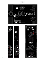 2
2
-
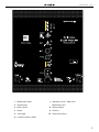 3
3
-
 4
4
-
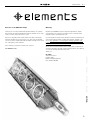 5
5
-
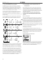 6
6
-
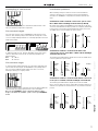 7
7
-
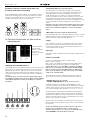 8
8
-
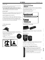 9
9
-
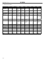 10
10
-
 11
11
-
 12
12
-
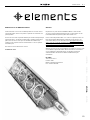 13
13
-
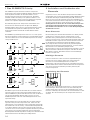 14
14
-
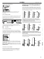 15
15
-
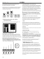 16
16
-
 17
17
-
 18
18
-
 19
19
-
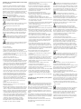 20
20
-
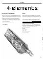 21
21
-
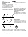 22
22
-
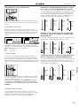 23
23
-
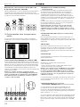 24
24
-
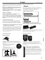 25
25
-
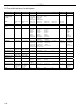 26
26
-
 27
27
-
 28
28
-
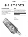 29
29
-
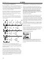 30
30
-
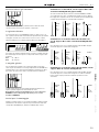 31
31
-
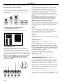 32
32
-
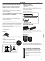 33
33
-
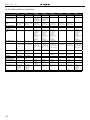 34
34
-
 35
35
-
 36
36
-
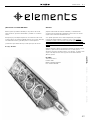 37
37
-
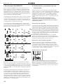 38
38
-
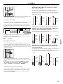 39
39
-
 40
40
-
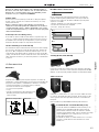 41
41
-
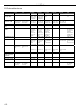 42
42
-
 43
43
-
 44
44
-
 45
45
-
 46
46
-
 47
47
-
 48
48


HK Audio BIG BASE SINGLE Manual de usuario
- Categoría
- Altavoces de la barra de sonido
- Tipo
- Manual de usuario
- Este manual también es adecuado para
en otros idiomas
- français: HK Audio BIG BASE SINGLE Manuel utilisateur
- italiano: HK Audio BIG BASE SINGLE Manuale utente
- Deutsch: HK Audio BIG BASE SINGLE Benutzerhandbuch