
Relé de corriente de circuito residual
Corriente residual de la serie RCAR
Relé diferencial
RCAR-A3010 (Código: 0135001)
Instrucciones de instalación y operación

Relé de corriente de circuito residual
TEMPER ENERGY INTERNATIONAL SL
Declaración
Lea atentamente este manual antes de utilizar estos productos, en los que las imágenes,
logotipos, símbolos, etc. involucrados están todos reservados por Temper Energy S.L. El personal
que no pertenezca a la empresa no podrá reimprimir públicamente todo o parte del contenido sin
autorización escrita.
Antes de usar el producto, lea los consejos y precauciones de este manual de operación. Temper
no se responsabiliza por lesiones personales o pérdidas económicas causadas por ignorar los
consejos de este manual.
El contenido del manual se actualizará y revisará continuamente, por lo que las funciones de los
productos en este manual pueden tener inevitablemente una ligera discrepancia con los objetos
reales durante el proceso de actualización continua. Los usuarios deben dar el primer lugar a los
productos reales comprados y pueden buscar en www. acrel.cn para descargas o a través de canales
de venta para obtener la última versión del manual.

Relé de corriente de circuito residual
Contenido
1. Introducción ...................................................................................................................................... 1
2. Tipos de producto .............................................................................................................................. 1
3. Parámetros técnicos .......................................................................................................................... 1
4. Instalación y conexión ...................................................................................................................... 2
4.1 Forma, dimensiones e instalación ............................................................................................ 2
4.2 Instrucciones de instalación ..................................................................................................... 3
4.2.1 Pasos de instalación ....................................................................................................... 3
4.2.2 Instalación de accesorios................................................................................................ 3
4.3 Terminales y cableado .............................................................................................................. 3
4.4 Asuntos que requieren atención ............................................................................................... 3
5. Guía de funcionamiento .................................................................................................................... 4
5.1 Descripción del panel tipo A .................................................................................................... 4
5.4 Descripción de la selección ...................................................................................................... 4
5.5 Instrucciones para la selección del transformador ................................................................... 6
6. Aplicaciones típicas .......................................................................................................................... 6

Relé de corriente de circuito residual
1
TEMPER ENERGY INTERNATIONAL SL
Relé operado por corriente residual serie RCAR
1. Introducción
El relé opera con corriente residual de la serie RCAR se puede combinar con un interruptor de
circuito de baja tensión
o un contactor
de bajo voltaje para formar un dispositivo de protección de
corriente residual, que se utiliza principalmente para las líneas de distribución del sistema TT y TN
con
50 Hz
AC
y
tensión
nominal de 400 V y menos. Se utiliza para proteger el circuito eléctrico de
fallas
a
tierra,
evitar
daños
en
el
equipo
causados
por
corrientes
de
falla
a
tierra
y
accidentes
por
incendios eléctricos. También se puede usar para proporcionar protección de contacto indirecto contra
el riesgo de descarga eléctrica personal.
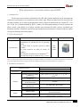
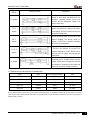
2.
Tipos de producto
Tipo Función Instalación Apariencia
RCAR-A3010
Medición de corriente residual tipo A;
Visualización de columna de luz de porcentaje
actual.
Se puede medir la corriente operativa residual
nominal.
Se puede establecer un límite de tiempo sin
conducir.
Dos conjuntos de salida de relé (configurable)nota 1;
Con funciones locales y remotas de “test” y “reset”.
Guía
(DIN
35 mm)
Nota 1: La función de configuración de relé significa que puede configurar la inicialización y el estado de salida del relé usted mismo
a través del código de marcación en el panel; la guía de configuración específica se puede encontrar en el capítulo 5.2.
3. Parámetros técnicos
Parámetros técnico Indicador
Tipo A
Fuente de
alimentación Rango de tensión AC/DC85~265V
Disipación de potencia ≤5W
Entrada
Corriente operativa residual
nominal I△n 0.03、0.05、0.1、0.3、0.5、1、3、5、10、
30(A)nota 3
Limite el tiempo sin
conducir △t 0,0,06,0,1,0,2,0,3,0,5,0,8,1,4,10(s)nota 4
Corriente nominal residual
no operativa I△no 50%I△n
Características de
presentación AC sinusoidal y DC pulsante
Frecuencia 50Hz±5Hz
Rango de operación -20% ~ -10%I△n
Salida Modo de salida Uno es normalmente cerrado o abierto, y otro es
para transformación.
Capacidad de contacto AL1:8A 250VAC; 5A 30 VCC
AL2:6A 250VAC; 5A 30 VCC

Relé de corriente de circuito residual
2
TEMPER ENERGY INTERNATIONAL SL
Modo de reinicio
Reinicio local, reinicio remoto o reinicio
automático
Entorno de
instalación y uso
Temperatura
Temperatura de funcionamiento: -20 ℃ ~ +55 ℃,
temperatura de almacenamiento: -30 ℃ ~ +70 ℃
Humedad
≤95 % de HR, sin condensación ni lugares con
gases corrosivos
Elevación
≤2000m
Clase de contaminación
Tercer grado
Categoría de instalación
Tipo Ⅲ
Nota 3: RCAR-A3010 corriente nominal residual de operación IΔn es 10mA~30A continuamente ajustable.
Nota 4: RCAR-A3010 límite de tiempo sin conducción Δt es 0~10S continuamente ajustable.
4. Instalación y conexión
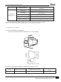
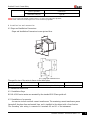
4.1 Forma, dimensiones e instalación
La forma y las dimensiones de instalación se ven en la imagen.
Imagen 1 Forma y tamaño
El tamaño específico del medidor se muestra en la siguiente tabla.
Tipo
Tamaño del panel (mm)
Tamaño de la carcasa (mm)
Tamaño del agujero
(mm)
RCAR-A3010
/
85*54*64 (largo*ancho*alto)
/

Relé de corriente de circuito residual
3
TEMPER ENERGY INTERNATIONAL SL
4.2 Instrucciones de instalación
4.2.1 Pasos de instalación
Los medidores de la serie RCAR-A3010 están montados en carril DIN-35 mm.
4.2.2 Instalación de accesorios
Los accesorios incluyen transformadores de corriente residual. El transformador de corriente
restante pasa por todas las líneas de fase y líneas de neutro, y se instala en el gabinete de fijación firme.
El cableado del lado secundario se conecta a los terminales 40 y 41 del instrumento.
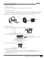
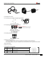
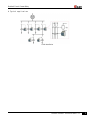
4.3 Terminales y cableado
4.3.1 Fuente de alimentación auxiliar y terminal de entrada de señal
Fuente de alimentación auxiliar Entrada de señal
4.3.2 Terminal de entrada/salida de cantidad de conmutación
Terminal de salida de relé
(sin fuente de alimentación auxiliar)
AL1:Relé de alarma
AL2: Relé de advertencia
4.3.3 Terminales funcionales adicionales
Restablecimiento remoto de prueba remota
4.4 Asuntos que requieren atención
A) El cable de puesta a tierra (PE) no debe atravesar el resto del transformador de corriente.
B) Para la red eléctrica monofásica, solo las líneas de fase y las líneas neutras deben atravesar en
el transformador de corriente residual.
Conexionado a la bobina de emisión
Borna 96 - conexionado a fase directa
Borna 95 - conexionado a la entrada de la bobina de emisión

Relé de corriente de circuito residual
4
TEMPER ENERGY INTERNATIONAL SL
5. Guía de funcionamiento
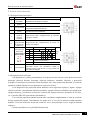
5.1 Descripción del panel tipo A
No. Nombre Función
1 Luz de
encendido Se enciende continuamente cuando la fuente de
alimentación de trabajo es normal
2 Botón de
reinicio Para restablecer el sistema
3 Luz de alarma Se enciende cuando se excede la corriente de
operación residual nominal I△n
4 Botón de
prueba Para probar si la luz indicadora es normal y el relé
puede funcionar normalmente
5
Interruptor de
ajuste de
corriente
residual
Proporcionar cuatro configuraciones de corriente
operativa residual
6
Interruptor de
ajuste de límite
de tiempo sin
conducción
Proporcionar dos configuraciones de límite de
tiempo sin conducir
7
Interruptor de
marcación
Dial Relé AL2 Relé AL1
Esta
do
A B 10 9 97 96 95
0 0
0 1
1 0 Advertencia
1 1 Alarma
C 0: Reinicio manual
1: Reinicio automático
D Reserva
8 Luz indicadora
Tres LED verdes se combinan para mostrar el
porcentaje actual, que parpadeará cuando la
corriente alcance más del 50 %, lo que indica una
advertencia temprana.
5.4 Descripción de la selección
1) El dispositivo se utiliza principalmente en la protección del sistema, como protección contra
descargas eléctricas directas, descargas eléctricas indirectas, incendios eléctricos y protección
jerárquica. Para dirigir la protección contra descargas solo como protección adicional, la corriente
operativa residual nominal en este momento no supera los 30 mA.
2) Los dispositivos de protección deben instalarse en los siguientes equipos y lugares: equipos
eléctricos móviles y herramientas eléctricas portátiles, equipos eléctricos utilizados en la producción,
equipos eléctricos y mecánicos en obras de construcción, equipos eléctricos instalados al aire libre,
etc. (Consulte GB13955 para obtener más detalles).
3) La corriente operativa nominal restante debe considerar completamente el valor de corriente
de fuga normal del sistema. Generalmente, no menos de 2~4 veces de la corriente residual máxima
medida: 4 veces de la línea de derivación; ramal 2,5 veces; línea principal 2 veces. Según la fórmula
empírica:
Circuito monofásico: I△n ≥In/2000 (iluminación)
Colocación del
dial estándar
A - 0
B - 1
C - 0
D - 0

Relé de corriente de circuito residual
5
TEMPER ENERGY INTERNATIONAL SL
Bucle trifásico: I△n ≥In/1000 (potencia o híbrido potencia iluminación) I△n es la corriente
máxima.
4) Para asegurar la selectividad de la acción de protección jerárquica, la coordinación de corriente
y tiempo entre los niveles superior e inferior se ajustará a las siguientes disposiciones:
I△n1 (superior) ≥I△n2 (inferior)
tF (tiempo de retorno RCAR superior) > tFA (tiempo de descanso RCAR inferior), la diferencia
de tiempo no es inferior a 0,2 s.
Ramal general y final: 30~100mA, ≤0.1s; Ramal: 300~500mA, 0.2~0.8S;
Línea principal: 500~1000mA, ≤2s.
5) Instrucciones de selección del sistema
Tipo de
sistema Cableado del sistema Descripción
Sistema
TT
Se recomienda RCAR. La corriente de falla a
tierra es muy pequeña y difícil de estimar, no
se puede alcanzar la corriente de operación y
la tensión peligrosa aparecerá en la carcasa.
Sistema
TN-S
Se puede utilizar RCAR. corta la falla de
manera más rápida y sensible, mejora la
seguridad y la confiabilidad. La línea PE no
puede pasar a través del transformador.
sistema
TN-C
RCAR no se puede usar, si la línea PEN no
es una puesta a tierra iterativa, el RCAR se
niega a operar; si la línea PEN es una puesta
a tierra iterativa, el RCAR funcionará
incorrectamente.
Sistema
TN-CS
Si es el sistema TN-C frente al punto F, no se
permite RCAR; si es el sistema TN-S en la
parte posterior del punto F, se puede usar
RCAR, pero la línea PE no puede pasar por
el transformador.
Sistema
IT
Se puede aplicar RCAR. El dispositivo de
monitoreo de aislamiento se aplica primero y
el dispositivo de corriente residual se aplica
para evitar la reducción del aislamiento en el
sistema y convertirlo en la protección de
respaldo secundaria.

Relé de corriente de circuito residual
6
TEMPER ENERGY INTERNATIONAL SL
5.5 Instrucciones para la selección del transformador
Tipo
Agujero
Corriente nominal del
bucle principal
Ratio
RCT-45
45 mm
80A
1A:1mA
RCT-80
80 mm
250A
1A:1mA
RCT-100
100 mm
400A
1A:1mA
RCT-150
150 mm
630A
1A:1mA
RCT-200
200 mm
1000A
1A:1mA
Nota: Se debe prestar atención al tipo de transformador de corriente residual, la apertura de instalación y la corriente nominal del circuito
principal para evitar la situación de que el cable de salida o la barra de cobre no puedan pasar a través del transformador. En caso de
duda, contáctenos.
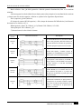
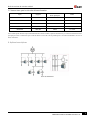
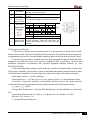
6. Aplicaciones típicas
Guía de instalación

Relé de corriente de circuito residual
7
TEMPER ENERGY INTERNATIONAL SL
GARANTÍA/GARANTÍA/GARANTÍA
3 años/años/años/años
ES – TEI garantiza este producto por 3 años ante defecto de fabricación. Para hacer esta garantía
válida, es imprescindible disponer de la factura de compra.
PT – TEI garantía este producto contra defectos de fábrica comió 3 años. Para validar esta garantía,
es esencial para una factura de compra.
FR – TEI garantit ce produit pour la durée de 3 années contre tout default de fabrication. Pour
valider cette garantie, il est essential d'avoir la facture d'achat.
ES – TEI Garantiza este producto por 3 años contra defecto de fabricación. Para hacer válida esta
garantía es imprescindible disponer de la factura de compra.

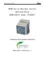
Residual Circuit Current Relay
RCAR Series Residual Current
Operated Relay
RCAR-A3010 (Code: 0135001)
Installation and Operation instruction
TEMPER ENERGY INTERNATIONAL S.L.

Residual Circuit Current Relay
Declaration
Please read this manual carefully before using these products, in which the involved pictures,
logos, symbols, etc. are all reserved by the Temper Energy S.L. Personnel not inside the company
shall not publicly reprint all or part of the contents without written authorization.
Before using the product, please read the tips and precautions in this operation manual, and
Temper does not take responsibility for personal injuries or economic losses caused by ignoring tips
of this manual.
The contents of the manual will be continuously updated and revised, thus the products
functions in this manual may inevitably have a slight discrepancy with the real objects during the
continuous upgrading process. Users should give first place to the purchased real products, and can
search www. acrel.cn to downloads or through sales channels to obtain the latest version of the
manual.

Residual Circuit Current Relay
Contents
1 Introduction ........................................................................................................................................ 1
2 Types of Products ............................................................................................................................... 1
3 Technical parameters .......................................................................................................................... 1
4 Installation and connection ................................................................................................................ 2
4.1 Shape and Installation Dimensions .......................................................................................... 2
4.2 Installation Instructions ............................................................................................................ 2
4.2.1 Installation Steps ............................................................................................................ 2
4.2.2 Installation of accessories .............................................................................................. 2
4.3 Terminals and wiring ............................................................................................................... 3
4.4 Matters needing attention ......................................................................................................... 3
5 Operating Guide ................................................................................................................................. 3
5.1 Description of AC type Panel .................................................................................................. 3
5.2 Description of A-type panel ..................................................................................................... 3
5.3 Description of LCD type panel ................................................................................................ 3
5.4 Description of Selection ........................................................................................................... 4
5.5 Instructions for the selection of transformer ............................................................................ 5
6 Typical applications ........................................................................................................................... 6

Residual Circuit Current Relay
1
TEMPER ENERGY INTERNATIONAL S.L.
RCAR series residual current operated relay
1 Introduction
RCAR series residual current operated relay can be combined with low voltage circuit breaker
or low voltage contactor to form a residual current protection device, which is mainly used for the
TT and TN system distribution lines with AC 50Hz and rated voltage of 400V and below. It is used
to protect the electrical circuit form ground faults, prevent equipment damage caused by earth fault
current and electrical fire accidents, and can also be used to provide indirect contact protection
against personal electric shock hazard.
2 Types of Products
Type
Function
Installation
Appearance
RCAR-A3010
A-type residual current measurement;
Current percentage light column display;
Rated residual operating current can be measured;
Limit non-driving time can be set;
Two sets of relay output (settable)note 1;
With local and remote “test” and “reset” functions.
Guide
(DIN
35mm)
Note 1: The function of setting for relay means that you can set the initialization and the output state of relay by yourself through the
code dialing on the panel; the specific setting guide can be found from the chapter 5.2.
3 Technical parameters
Technical Parameter
Indicator
A type
Power supply
Voltage range
AC/DC85~265V
Power dissipation
≤5W
Input
Rated residual operating
current I△n
0.03、0.05、0.1、0.3、0.5、1、3、5、10、30(A)note
3
Limit non-driving time △t
0、0.06、0.1、0.2、0.3、0.5、0.8、1、4、10(s)note
4
Rated residual non-operating
current I△no
50%I△n
Performance characteristics
Sinusoidal AC and pulsating DC
Frequency
50Hz±5Hz
Operating range
-20% ~ -10%I△n
Output
Output mode
One is normally closed or open, and another is for
transformation
Contact capacity
AL1:8A 250VAC; 5A 30VDC
AL2:6A 250VAC; 5A 30VDC
Reset mode
Local reset, remote reset or automatic reset
Installation and
use environment
Temperature
Run temperature:-20℃ ~ +55℃,Storage
temperature:-30℃ ~ +70℃
Humidity
≤95%RH,no condensation, and no corrosive gas
places
Elevation
≤2000m

Residual Circuit Current Relay
2
TEMPER ENERGY INTERNATIONAL S.L.
Class of pollution Grade three
Installation category Type Ⅲ
Note 3: RCAR-A3010 rated residual operating current IΔn is 10mA~30A continuously adjustable;
Note 4: RCAR-A3010 limit non-driving time Δt is 0~10S continuously adjustable.
4 Installation and connection
4.1 Shape and Installation Dimensions
Shape and Installation Dimensions is seen picture blow.
Pic 1 Shape and Installation size
The specific size of the meter is shown in the table below.
type Panel size (mm) Shell size (mm) Hole size (mm)
RCAR-A3010 / 85*54*64 (length*width*height) /
4.2 Installation Instructions
4.2.1 Installation Steps
RCAR-A3010 series meters are mounted by the standard DIN-35mm guide rail.
4.2.2 Installation of accessories
Accessories include residual current transformers. The remaining current transformer passes
through all the phase lines and neutral lines, and is installed in the cabinet with a firm fixation.
The secondary side wiring is connected to terminals 40 and 41 of the instrument.

Residual Circuit Current Relay
3
TEMPER ENERGY INTERNATIONAL S.L.
4.3 Terminals and wiring
4.3.1 Auxiliary power supply and signal input terminal
Auxiliary power supply Signal input
4.3.2 Switching quantity input/output terminal
Relay output terminal
(no auxiliary power supply)
AL1: Alarm relay
AL2:warning relay
4.3.3 Additional functional terminals
Remote test remote reset
4.4 Matters needing attention
A) The grounding wire (PE) shall not penetrate the remaining current transformer.
B) For single-phase power grid, only phase lines and neutral lines need to penetrate the residual
current transformer.
5 Operating Guide
5.1 Description of A-type panel
No. Name Function
1 Power light Lights continuously when the working power
supply is normal
2 Reset button To reset the system
3 Alarm light Lights when the rated residual operating current
I△n is exceeded
Connection to shunt coil
Terminal 96 - connection directly to phase (L)
Terminal 95 - connection to shunt coil input

Residual Circuit Current Relay
4
TEMPER ENERGY INTERNATIONAL S.L.
4 Test button To test whether the indicator light is normal, and
the relay can operate normally.
5 residual current
set switch Providing four settings of residual operating
current
6 limit
non-driving
time set switch Providing two settings of limit non-driving time
7
Dial switch
dial Relay AL2 Relay AL1
State
A B 10 9 97 96 95
0 0
0 1
1 0 warning
1 1 alarm
C 0: manual reset, 1: automatic reset
D reserve
8 Indicator light
with streamer
Three green LEDs are combined to show the
current percentage, which will flash when the
current reaches more than 50%, indicating early
warning.
5.4 Description of Selection
1) The device is mainly used in system protection, as the protection of direct electric shock,
indirect electric shock, electrical fire and hierarchical protection. For directing shock protection only
as supplementary protection, the rated residual operating current at this time does not exceed 30mA.
2) Protective devices must be installed in the following equipment and places: mobile electrical
equipment and hand-held power tools, electrical equipment used in production, electrical and
mechanical equipment in construction sites, electrical equipment installed outdoors, etc. (See
GB13955 for details).
3) The rated remaining operating current shall fully consider the normal leakage current value
of the system. Generally, not less than 2~4 times of the maximum measured residual current: 4 times
of the branch line; Branch line 2.5 times; Main line 2 times. According to the empirical formula:
Single-phase circuit: I△n ≥In/2000 (lighting)
Three-phase loop: I△n ≥In/1000 (power or power lighting hybrid) I△n is the maximum current.
4) In order to ensure the selectivity of hierarchical protection action, the current and time
coordination between the upper and lower levels shall conform to the following provisions:
I△n1 (upper) ≥I△n2 (lower)
tF (upper RCAR return time) > tFA (low RCAR break time), the time difference is not less than
0.2s. General branch line and end: 30~100mA, ≤0.1s;Branch line: 300~500mA, 0.2~0.8S;
Main line: 500~1000mA, ≤2s.
5)System Selection Instructions
Standard dial
colocation
A - 0
B - 1
C - 0
D - 0

Residual Circuit Current Relay
5
TEMPER ENERGY INTERNATIONAL S.L.
Type of
system Wiring of system description
TT system
RCAR is recommended. The earth fault
current is very small and difficult to be
estimated, operating current can not be
reached, and the hazardous voltage will
appear on the shell.
TN-S
system
RCAR can be used. cut off the fault more
quickly and sensitively, improve the safety
and reliability. PE line is not allowed to pass
through the transformer.
TN-C
system
RCAR can not be used, if PEN line is not
iterative earthing, the RCAR refuse to
operate; if PEN line is iterative earthing,
RCAR will be misoperated.
TN-C-S
system
If it is the TN-C system in front of the point
F, RCAR is not allowed; if it is the TN-S
system at the back of point F, RCAR can be
used, but PE line cannot pass through the
transformer.
IT system
RCAR can be applied. The insulation
monitoring device is applied firstly and the
residual current device is applied to prevent
the reduction of insulation in the system and
make it the secondary backup protection.
5.5 Instructions for the selection of transformer
type hole Main loop rated current ratio
RCT-45 45mm 80A 1A:1mA
RCT-80 80mm 250A 1A:1mA
RCT-100 100mm 400A 1A:1mA
RCT-150 150mm 630A 1A:1mA
RCT-200 200mm 1000A 1A:1mA
Note: Attention should be paid to the type of residual current transformer, the installation aperture and the rated current of the main
circuit to prevent the situation that the outlet cable or copper bar cannot all pass through the transformer. If the above type cannot be
satisfied, please contact us.

Residual Circuit Current Relay
6
TEMPER ENERGY INTERNATIONAL S.L.
6 Typical applications
Guide installation

Residual Circuit Current Relay
7
TEMPER ENERGY INTERNATIONAL S.L.
GARANTÍA/GUARANTEE/GARANTIE
3 años/anos/années/years
ES – T.E.I. garantiza este producto por 3 años ante defecto de fabricación. Para hacer válida esta
garantía, es imprescindible disponer de la factura de compra.
PT – T.E.I. garantía este produto contra defeitos de fábrica ate 3 anos. Para validar esta garantia,
é essencial ter a facture da compra.
FR – T.E.I. garantit ce produit pour la durée de 3 années contre tout default de fabrication. Pour
valider cette garantie, il est essential d'avoir la facture d'achat.
EN – T.E.I. Guarantees this product for 3 years against manufacturing defect. To make this
guarantee valid, it is essential to have the purchase invoice.
-
 1
1
-
 2
2
-
 3
3
-
 4
4
-
 5
5
-
 6
6
-
 7
7
-
 8
8
-
 9
9
-
 10
10
-
 11
11
-
 12
12
-
 13
13
-
 14
14
-
 15
15
-
 16
16
-
 17
17
-
 18
18
-
 19
19
-
 20
20


Crady RCT-150 El manual del propietario
- Tipo
- El manual del propietario
en otros idiomas
- English: Crady RCT-150 Owner's manual
Otros documentos
-
Samsung SF4000 Manual de usuario
-
 Boss Audio Systems 612UA Manual de usuario
-
Nintendo Mario Tennis: Ultra Smash El manual del propietario
-
-
CAME ATI 24V Installation and User Manual
-
Yamaha PSR-6700 El manual del propietario
-
-
-
Hasselblad X1D II 50C Manual de usuario
-
CARLO GAVAZZI WM30AV43H El manual del propietario
