Yamaha FS1R El manual del propietario
- Categoría
- Instrumentos musicales
- Tipo
- El manual del propietario

OWNER’S MANUAL

PRODUCT SAFETY MARKINGS: Yamaha electronic
products may have either labels similar to the graphics shown
below or molded/stamped facsimiles of these graphics on the
enclosure. The explanation of these graphics appears on this
page. Please observe all cautions indicated on this page and
those indicated in the safety instruction section.
ENVIRONMENTAL ISSUES: Yamaha strives to produce
products that are both user safe and environmentally friendly.
We sincerely believe that our products and the production
methods used to produce them, meet these goals. In keeping
with both the letter and the spirit of the law, we want you to be
aware of the following:
Battery Notice: This product MAY contain a small non-
rechargable battery which (if applicable) is soldered in place.
The average life span of this type of battery is approximately
five years. When replacement becomes necessary, contact a
qualified service representative to perform the replacement.
Warning: Do not attempt to recharge, disassemble, or
incinerate this type of battery. Keep all batteries away from
children. Dispose of used batteries promptly and as regulated
by applicable laws. Note: In some areas, the servicer is
required by law to return the defective parts. However, you do
have the option of having the servicer dispose of these parts
for you.
Disposal Notice: Should this product become damaged
beyond repair, or for some reason its useful life is considered
to be at an end, please observe all local, state, and federal
regulations that relate to the disposal of products that contain
lead, batteries, plastics, etc.
NOTICE: Service charges incurred due to lack of knowledge
relating to how a function or effect works (when the unit is
operating as designed) are not covered by the manufacturer’s
warranty, and are therefore the owners responsibility. Please
study this manual carefully and consult your dealer before
requesting service.
NAME PLATE LOCATION: The graphic below indicates the
location of the name plate. The model number, serial number,
power requirements, etc., are located on this plate. You should
record the model number, serial number, and the date of
purchase in the spaces provided below and retain this manual
as a permanent record of your purchase.
Model
Serial No.
Purchase Date
CAUTION: TO REDUCE THE RISK OF ELECTRIC SHOCK.
DO NOT REMOVE COVER (OR BACK).
NO USER-SERVICEABLE PARTS INSIDE.
REFER SERVICING TO QUALIFIED SERVICE PERSONNEL.
The exclamation point within the equi-
lateral triangle is intended to alert the
user to the presence of important oper-
ating and maintenance (servicing)
instructions in the literature accompa-
nying the product.
The lightning flash with arrowhead
symbol, within the equilateral triangle,
is intended to alert the user to the pres-
ence of uninsulated “dangerous volt-
age” within the product’s enclosure
that may be of sufficient magnitude to
constitute a risk of electrical shock.
IMPORTANT NOTICE: All Yamaha electronic products are
tested and approved by an independent safety testing
laboratory in order that you may be sure that when it is
properly installed and used in its normal and customary
manner, all foreseeable risks have been eliminated. DO NOT
modify this unit or commission others to do so unless
specifically authorized by Yamaha. Product performance
and/or safety standards may be diminished. Claims filed under
the expressed warranty may be denied if the unit is/has been
modified. Implied warranties may also be affected.
SPECIFICATIONS SUBJECT TO CHANGE: The information
contained in this manual is believed to be correct at the time
of printing. However, Yamaha reserves the right to change or
modify any of the specifications without notice or obligation to
update existing units.
SPECIAL MESSAGE SECTION
92-469- 1
RISK OFELECTRIC SHOCK
DO NOT OPEN
CAUTION
FCC/E/qx 9/24/98 8:19 PM Page 2

92-469- 3
IMPORTANT SAFETY INSTRUCTIONS
INFORMATION RELATING TO PERSONAL INJURY, ELECTRICAL SHOCK,
AND FIRE HAZARD POSSIBILITIES HAS BEEN INCLUDED IN THIS LIST.
WARNING- When using any electrical or electronic product,
basic precautions should always be followed. These
precautions include, but are not limited to, the following:
1. Read all Safety Instructions, Installation Instructions,
Special Message Section items, and any Assembly
Instructions found in this manual BEFORE making any
connections, including connection to the main supply.
2. Do not attempt to service this product beyond that
described in the user-maintenance instructions. All other
servicing should be referred to qualified service personnel.
3. Main Power Supply Verification: Yamaha products are
manufactured specifically for the supply voltage in the area
where they are to be sold. If you should move, or if any doubt
exists about the supply voltage in your area, please contact
your dealer for supply voltage verification and (if applicable)
instructions. The required supply voltage is printed on the
name plate. For name plate location, please refer to the
graphic found in the Special Message Section of this manual.
4. DANGER-Grounding Instructions: This product must be
grounded and therefore has been equipped with a three pin
attachment plug. If this product should malfunction, the ground
pin provides a path of low resistance for electrical current,
reducing the risk of electrical shock. If your wall socket will not
accommodate this type plug, contact an electrician to have
the outlet replaced in accordance with local electrical codes.
Do NOT modify the plug or change the plug to a different type!
5. WARNING: Do not place this product or any other
objects on the power cord or place it in a position where
anyone could walk on, trip over, or roll anything over power or
connecting cords of any kind. The use of an extension cord is
not recommended! If you must use an extension cord, the
minimum wire size for a 25' cord (or less) is 18 AWG. NOTE:
The smaller the AWG number, the larger the current handling
capacity. For longer extension cords, consult a local
electrician.
6. Ventilation: Electronic products, unless specifically
designed for enclosed installations, should be placed in
locations that do not interfere with proper ventilation. If
instructions for enclosed installations are not provided, it must
be assumed that unobstructed ventilation is required.
7. Temperature considerations: Electronic products should
be installed in locations that do not seriously contribute to their
operating temperature. Placement of this product close to heat
sources such as; radiators, heat registers etc., should be
avoided.
8. This product was NOT designed for use in wet/damp
locations and should not be used near water or exposed to
rain. Examples of wet /damp locations are; near a swimming
pool, spa, tub, sink, or wet basement.
9. This product should be used only with the components
supplied or; a cart ,rack, or stand that is recommended by the
manufacturer. If a cart, rack, or stand is used, please observe
all safety markings and instructions that accompany the
accessory product.
10. The power supply cord (plug) should be disconnected
from the outlet when electronic products are to be left unused
for extended periods of time. Cords should also be
disconnected when there is a high probability of lightening
and/or electrical storm activity.
11. Care should be taken that objects do not fall and
liquids are not spilled into the enclosure through any openings
that may exist.
12. Electrical/electronic products should be serviced by a
qualified service person when:
a. The power supply cord has been damaged; or
b. Objects have fallen, been inserted, or liquids have
been spilled into the enclosure through openings; or
c. The product has been exposed to rain; or
d. The product does not operate, exhibits a marked
change in performance; or
e. The product has been dropped, or the enclosure of the
product has been damaged.
13. This product, either alone or in combination with an
amplifier and headphones or speaker/s, may be capable of
producing sound levels that could cause permanent hearing
loss. DO NOT operate for a long period of time at a high
volume level or at a level that is uncomfortable. If you
experience any hearing loss or ringing in the ears, you should
consult an audiologist.
IMPORTANT: The louder the sound, the shorter the time
period before damage occurs.
14. Some Yamaha products may have benches and/or
accessory mounting fixtures that are either supplied as a part
of the product or as optional accessories. Some of these items
are designed to be dealer assembled or installed. Please
make sure that benches are stable and any optional fixtures
(where applicable) are well secured BEFORE using. Benches
supplied by Yamaha are designed for seating only. No other
uses are recommended.
PLEASE KEEP THIS MANUAL
FCC/E/qx 9/24/98 8:19 PM Page 3

1. IMPORTANT NOTICE: DO NOT MODIFY THIS UNIT!
This product, when installed as indicated in the instructions
contained in this manual, meets FCC requirements. Modifications
not expressly approved by Yamaha may void your authority, granted
by the FCC, to use the product.
2. IMPORTANT: When connecting this product to accessories and/or
another product use only high quality shielded cables. Cable/s
supplied with this product MUST be used. Follow all installation
instructions. Failure to follow instructions could void your FCC
authorization to use this product in the USA.
3. NOTE: This product has been tested and found to comply with the
requirements listed in FCC Regulations, Part 15 for Class “B” digital
devices. Compliance with these requirements provides a
reasonable level of assurance that your use of this product in a
residential environment will not result in harmful interference with
other electronic devices. This equipment generates/uses radio
frequencies and, if not installed and used according to the
instructions found in the users manual, may cause interference
harmful to the operation of other electronic devices. Compliance
with FCC regulations does not guarantee that interference will not
occur in all installations. If this product is found to be the source of
interference, which can be determined by turning the unit “OFF”
and “ON”, please try to eliminate the problem by using one of the
following measures:
Relocate either this product or the device that is being affected by
the interference.
Utilize power outlets that are on different branch (circuit breaker or
fuse) circuits or install AC line filter/s.
In the case of radio or TV interference, relocate/reorient the
antenna. If the antenna lead-in is 300 ohm ribbon lead, change the
lead-in to co-axial type cable.
If these corrective measures do not produce satisfactory results,
please contact the local retailer authorized to distribute this type of
product. If you can not locate the appropriate retailer, please contact
Yamaha Corporation of America, Electronic Service Division, 6600
Orangethorpe Ave, Buena Park, CA90620
The above statements apply ONLY to those products distributed by
Yamaha Corporation of America or its subsidiaries.
ADVARSEL!
Lithiumbatteri—Eksplosionsfare ved fejlagtig håndtering. Udskiftning
må kun ske med batteri af samme fabrikat og type. Levér det brugte
batteri tilbage til leverandoren.
VARNING
Explosionsfara vid felaktigt batteribyte. Använd samma batterityp
eller en ekvivalent typ som rekommenderas av apparattillverkaren.
Kassera använt batteri enlight fabrikantens instruktion.
VAROITUS
Paristo voi räjähtää, jos se on virheellisesti asennettu. Vaihda paristo
ainoastaan laitevalmistajan suosittelemaan tyyppiin. Hävitä käytetty
paristo valmistajan ohjeiden mukaisesti.
NEDERLAND / THE NETHERLANDS
• Dit apparaat bevat een lithium batterij voor geheugen back-up.
• This apparatus contains a lithium battery for memory back-up.
• Raadpleeg uw leverancier over de verwijdering van de batterij op
het moment dat u het apparaat ann het einde van de levensduur
afdankt of de volgende Yamaha Service Afdeiing:
Yamaha Music Nederland Service Afdeiing
Kanaalweg 18-G, 3526 KL UTRECHT
Tel. 030-2828425
• For the removal of the battery at the moment of the disposal at the
end of the service life please consult your retailer or Yamaha
Service Center as follows:
Yamaha Music Nederland Service Center
Address : Kanaalweg 18-G, 3526 KL UTRECHT
Tel : 030-2828425
• Gooi de batterij niet weg, maar lever hem in als KCA.
• Do not throw away the battery. Instead, hand it in as small chemical
waste.
IMPORTANT NOTICE FOR THE UNITED KINGDOM
Connecting the Plug and Cord
WARNING: THIS APPARATUS MUST BE EARTHED
IMPORTANT. The wires in this mains lead are coloured in
accordance with the following code:
GREEN-AND-YELLOW: EARTH
BLUE : NEUTRAL
BROWN : LIVE
As the colours of the wires in the mains lead of this apparatus
may not correspond with the coloured markings identifying the
terminals in your plug proceed as follows:
The wire which is coloured GREEN-and-YELLOW must be
connected to the terminal in the plug which is marked by the
letter E or by the safety earth symbol or colored GREEN or
GREEN-and-YELLOW.
The wire which is coloured BLUE must be connected to the
terminal which is marked with the letter N or coloured BLACK.
The wire which is coloured BROWN must be connected to the
terminal which is marked with the letter L or coloured RED.
* This applies only to products distributed by YAMAHA CORPORATION OF AMERICA.
FCC INFORMATION (U.S.A.)
• This applies only to products distributed by Yamaha-Kemble Music (U.K.) Ltd.
FCC/E/qx 11/12/98 5:52 PM Page 4

PRECAUTIONS
PLEASE READ CAREFULLY BEFORE PROCEEDING
* Please keep these precautions in a safe place for future reference.
WARNING
Always follow the basic precautions listed below to avoid the possibility of serious injury or even death from electrical shock,
short-circuiting, damages, fire or other hazards. These precautions include, but are not limited to, the following:
• Do not open the instrument or attempt to disassemble the internal parts or
modify them in any way. The instrument contains no user-serviceable parts. If
it should appear to be malfunctioning, discontinue use immediately and have
it inspected by qualified Yamaha service personnel.
• Do not expose the instrument to rain, use it near water or in damp or wet
conditions, or place containers on it containing liquids which might spill into
any openings.
• If the power cord or plug becomes frayed or damaged, or if there is a sudden
loss of sound during use of the instrument, or if any unusual smells or smoke
should appear to be caused by it, immediately turn off the power switch,
disconnect the electric plug from the outlet, and have the instrument
inspected by qualified Yamaha service personnel.
• Only use the voltage specified as correct for the instrument. The required
voltage is printed on the name plate of the instrument.
• Always connect the three-pin attachment plug to a properly grounded power
source. (For more information about the main power supply, see page 17.)
• Before cleaning the instrument, always remove the electric plug from the
outlet. Never insert or remove an electric plug with wet hands.
• Check the electric plug periodically and remove any dirt or dust which may
have accumulated on it.
CAUTION
Always follow the basic precautions listed below to avoid the possibility of physical injury to you or others, or damage to the
instrument or other property. These precautions include, but are not limited to, the following:
• Do not place the power cord near heat sources such as heaters or radiators,
and do not excessively bend or otherwise damage the cord, place heavy
objects on it, or place it in a position where anyone could walk on, trip over,
or roll anything over it.
• When removing the electric plug from the instrument or an outlet, always hold
the plug itself and not the cord. Pulling by the cord can damage it.
• Do not connect the instrument to an electrical outlet using a multiple-
connector. Doing so can result in lower sound quality, or possibly cause
overheating in the outlet.
• Remove the electric plug from the outlet when the instrument is not to be
used for extended periods of time, or during electrical storms.
• Before connecting the instrument to other electronic components, turn off the
power for all components. Before turning the power on or off for all
components, set all volume levels to minimum.
• Do not expose the instrument to excessive dust or vibrations, or extreme cold
or heat (such as in direct sunlight, near a heater, or in a car during the day) to
prevent the possibility of panel disfiguration or damage to the internal
components.
• Do not use the instrument near other electrical products such as televisions,
radios, or speakers, since this might cause interference which can affect
proper operation of the other products.
• Do not place the instrument in an unstable position where it might
accidentally fall over.
• Before moving the instrument, remove all connected cables.
• When cleaning the instrument, use a soft, dry cloth. Do not use paint
thinners, solvents, cleaning fluids, or chemical-impregnated wiping cloths.
Also, do not place vinyl, plastic or rubber objects on the instrument, since
this might discolor the panel or keyboard.
• Do not rest your weight on, or place heavy objects on the instrument, and do
not use excessive force on the buttons, switches or connectors.
• Use only the stand/rack specified for the instrument. When attaching the
stand or rack, use the provided screws only. Failure to do so could cause
damage to the internal components or result in the instrument falling over.
• Do not operate the instrument for a long period of time at a high or
uncomfortable volume level, since this can cause permanent hearing loss. If
you experience any hearing loss or ringing in the ears, consult a physician.
■ REPLACING THE BACKUP BATTERY
• This instrument contains a non rechargeable internal backup battery which
permits internal data to remain stored even when the power is off. When the
backup battery needs replacing, the message "Battery Low" will display in the
LCD. When this happens, immediately back up your data (using an external
device such as the floppy disk-based Yamaha MIDI Data Filer MDF3), then have
qualified Yamaha service personnel replace the backup battery.
• Do not attempt to replace the backup battery yourself, in order to prevent the
possible serious hazards. Always have qualified Yamaha service personnel
replace the backup battery.
• Never place the backup battery in a location that a child can reach, since a
child might accidentally swallow the battery. If this should happen, consult a
physician immediately.
■ SAVING USER DATA
• Save all data to an external device such as the Yamaha MIDI Data Filer MDF3,
in order to help prevent the loss of important data due to a malfunction or
user operating error.
Yamaha cannot be held responsible for damage caused by improper use or
modifications to the instrument, or data that is lost or destroyed.
Always turn the power off when the instrument is not in use.
(1)-3
cPRECAUTIONS/E/qx 9/24/98 8:20 PM Page 5

6
Congratulations!
Your FS1R Format Shaping/FM Synthesis Tone Generator gives you the power of two extraordinary tone generation
systems in one compact, easy-to-use rack-mount unit. Formant Shaping synthesis gives musicians unprecedented
capability to produce and control sounds with characteristics and flexibility similar to that of the human voice. It can
also produce instrument voices that have the response and rich pitch-dependent timbral variations. FS technology
also lends itself ideally to FM synthesis, similar to the type introduced in the legendary Yamaha DX-series
synthesizers and TX-series tone generators. In addition to unprecedented voicing versatility and expressive scope,
the FS1R features an advanced control interface that facilitates both real-time performance control and editing.
Please read this owner’s manual carefully, and follow the instructions within in order to ensure proper operation. Also
keep this manual in a safe place for later reference.
1/FS1R/OM/E.qx 10/19/98 6:28 PM Page 6

7
Contents
FS (Formant Shaping) and
FM (Frequency Modulation) Synthesis........................8
FS Synthesis ......................................................................................8
*Formant Control...........................................................................9
*Formant Sequences:“FSeqs” ....................................................10
*Other Formant Applications ......................................................11
FM Synthesis....................................................................................11
*FM In Brief .................................................................................12
Putting It All Together.......................................................................13
The Controls & Connectors ........................................14
Front Panel.......................................................................................14
Rear Panel .......................................................................................16
Setting Up .....................................................................17
Power Supply...................................................................................17
MIDI Connections ............................................................................17
*Keyboard...................................................................................17
*Sequencer or Computer............................................................18
*G50 Guitar MIDI Converter .......................................................18
*WX-series Wind MIDI Controller................................................18
Audio Connections ..........................................................................19
*Headphones..............................................................................19
*Instrument Amplifier or Stereo Sound System ..........................19
*Mixing Console..........................................................................19
Power-on Procedure ........................................................................20
Play the Demo..................................................................................20
The PLAY Mode............................................................21
Performance & Voice Organization .................................................21
*Performance Combinations.......................................................21
*Voices ........................................................................................21
*Bank Selection via MIDI ............................................................22
The Play Mode (Performance).........................................................22
Perf Ch (Performance Channel) .................................................23
(Bank) .........................................................................................23
(Program Number)......................................................................23
Pfm Vol (Performance Volume)...................................................23
Pfm Pan (Performance Pan) .......................................................23
RevRtn (Reverb Return)..............................................................23
VarRtn (Variation Return) ............................................................24
PfmNSft (Performance Note Shift) ..............................................24
The PART ASSIGN Mode.................................................................24
Rcv Ch (Receive Channel) .........................................................25
Rcv Max (Maximum Receive Channel: parts 1 & 2 only)...........25
(Bank) .........................................................................................25
(Program Number)......................................................................25
Volume ........................................................................................25
Pan..............................................................................................25
RevSend (Reverb Send).............................................................26
VarSend (Variation Send)............................................................26
InsEfSw (Insertion Effect Switch)................................................26
DryLvl (Dry Level).......................................................................26
Filter (Filter Frequency Offset) ....................................................26
NoteSft (Note Shift) .....................................................................26
The [MUTE/SOLO] Button in the Part Assign Mode...................26
The Search Function.............................................................................27
EDITING.........................................................................28
General Editing Procedure ..............................................................28
The [MUTE/SOLO] Button in the Edit Modes .............................29
EDIT [PERFORMANCE] ...................................................................30
COMMON ...................................................................................30
*CtrlSrc (Control Source) .......................................................30
*CtrlDst (Control Destination) ................................................31
*Fseq (Format Sequence) .....................................................32
*Others...................................................................................35
PART ...........................................................................................37
*Tone......................................................................................37
*EG (Envelope Generator).....................................................39
*Pitch......................................................................................40
*Others...................................................................................41
STORE PERFORMANCE.............................................................44
RECALL PERFORMANCE...........................................................44
EDIT [EFFECT].................................................................................45
Effect Signal Flow .......................................................................45
Rev..............................................................................................45
Type .......................................................................................46
Type-Specific Reverb Parameters.........................................46
Reverb Pan ............................................................................46
Rev Return .............................................................................46
Var...............................................................................................46
Type .......................................................................................46
Type-Specific Variation Parameters.......................................46
Var Pan ..................................................................................47
Var Return ..............................................................................47
SendVar→Rev ........................................................................47
Ins ...............................................................................................47
Type .......................................................................................47
Type-Specific Insertion Parameters.......................................47
Ins Pan...................................................................................47
SendIns→Rev.........................................................................48
SendIns→Var..........................................................................48
InsDryLevel............................................................................48
EQ ...............................................................................................48
Low Freq................................................................................48
Low Gain................................................................................48
Low Q ....................................................................................48
Low Shape.............................................................................48
Mid Freq.................................................................................49
Mid Gain ................................................................................49
Mid Q .....................................................................................49
High Freq...............................................................................49
High Gain...............................................................................49
High Q ...................................................................................49
High Shape............................................................................49
EDIT [VOICE] ...................................................................................50
COMMON ...................................................................................50
*LFO1 (Low Frequency Oscillator 1).....................................51
*LFO2 (Low Frequency Oscillator 2).....................................52
*Filter......................................................................................53
*PitchEG (Pitch Envelope Generator)....................................57
*Others...................................................................................58
OPERATOR .................................................................................61
*Osc (Oscillator) ....................................................................62
*EG (Amplitude Envelope Generator) ...................................66
*FrqEG (Frequency EG).........................................................67
*Sns (Sensitivity) ....................................................................68
STORE VOICE.............................................................................70
RECALL VOICE...........................................................................70
UTILITY Functions .......................................................71
SYSTEM ...........................................................................................71
*Master........................................................................................71
*MIDI ...........................................................................................72
*Control .......................................................................................74
*Others........................................................................................76
DUMPOUT .......................................................................................77
*DUMPOUT Operation................................................................77
INITIAL .............................................................................................78
DEMO...............................................................................................78
Troubleshooting ...........................................................79
Alert Display .................................................................82
Specifications...............................................................83
Index..............................................................................84
1/FS1R/OM/E.qx 10/19/98 6:28 PM Page 7

8
FS (Formant Shaping) and FM
(Frequency Modulation) Synthesis
FS (Formant Shaping) and
FM (Frequency Modulation) Synthesis
Although based on Yamaha’s newly developed FS (Formant Shaping) synthesis technology, The FS1R actually
integrates two tone generation concepts for extraordinarily broad voicing versatility. Formant Shaping synthesis
gives musicians unprecedented capability to produce and control sounds with characteristics and flexibility similar
to that of the human voice. It can also produce instrument voices that have the response and rich pitch-dependent
timbral variations — in short, the “musicality” — of natural acoustic instruments. The bonus is that the base FS
technology has been realized using an architecture which also lends itself ideally to FM synthesis, similar to the type
introduced in the legendary Yamaha DX-series synthesizers and TX-series tone generators. Thus the FS1R can
create anything from totally new simulations of human vocal sounds to classic DX electric piano voices, and
anything in between.
FS Synthesis
The term “formant” refers to the distinct spectral patterns which define the recognizable sounds of human speech,
such as the vowels “a” or “i.” In human speech, the vocal cords themselves are only capable of creating the basic
driving sound and defining pitch (similar to the oscillator in a music synthesis system). The formants which define
the sounds of speech are created by the shape of the vocal cavity (i.e. the trachea and mouth). In traditional speech
synthesis systems this is simulated by using an oscillator to perform the function of the vocal cords, and a series of
controllable bandpass filters to create the required format shapes. Consonant sounds such as “k” or “t,” and
fricatives such as “f,” are based on slightly different principles, requiring a noise generator rather than an oscillator,
and depending more on amplitude envelope shape than formant shape for recognizability. Formants play an
important role in defining the sound of many acoustic musical instruments as well as the human voice.
Rather than a cumbersome system of oscillators and filters to synthesize the effect of formants, the FS synthesis
system consists of 16 formant “operators” — 8 “voiced” operators, and 8 “unvoiced” operators (3 to 5 formants are
generally considered to be more than enough to synthesize speech). Each operator digitally simulates the effect of
both the driving source (oscillator) and filter in one easily manageable unit. The voiced operators produced pitched
sounds which can be played on a musical scale via a MIDI keyboard or other MIDI controller. The unvoiced
operators can be used to produce noise components of speech-like sound, or they can be used in much the same
way as noise generators in more orthodox synthesis systems (e.g. to produce percussive sounds or sound effects).
The term “operators” is borrowed from Yamaha FM synthesis, because the FS1R’s voiced operators can be
combined in a variety of “algorithms” to create sound in exactly the same way as in the original FM synthesizers
such as the DX7.
1 2 3 4 5
Operators
Voiced
Unvoiced
Formants
6 7 8
1/FS1R/OM/E.qx 10/19/98 6:28 PM Page 8

■ Formant Control
Each formant operator has a range of parameters which determine its shape and therefore contribute to the overall
sound: center frequency, level, width, and skirt (the shape of the “flare” at the bottom of the formant’s bell-shaped
response curve).
As an example, suppose we have a formant configuration that produces an “a” type sound. This can be changed to
an “i” sound by shifting the center frequencies and levels of the formants. If this is done in real time at an
appropriate speed, we produce the sound “ai”.
This type of formant control can be accomplished in the FS1R in several ways. First, independent frequency and
level envelope generators are provided for each operator, so time-based timbral shifts like the one described above
can be achieved entirely by using the envelope generators. Second, any of the available controllers can be
assigned to the formant parameters — the control knobs, a modulation wheel, foot controller, etc. — to allow realtime
manual control while playing. Either of these methods of formant control are all you’ll need to create musical sounds
for most applications, but the last and most complex type of formant control on the FS1R is made possible by
“FSeqs” (Formant Sequences), described in the following section.
=“a”
=“i”
Level
Width
Skirt
Center Frequency
9
1/FS1R/OM/E.qx 10/19/98 6:28 PM Page 9

EG, LFO1, Velocity, and Manual Formant Control Parameters
The following parameter groups and parameters are essential for EG-based formant control. Refer to the
parameter descriptions for details:
• EDIT [VOICE] mode OPERATOR/Osc/.....................................................Page 62
• EDIT [VOICE] mode OPERATOR/EG/ ......................................................Page 66
• EDIT [VOICE] mode OPERATOR/FrqEG/ .................................................Page 67
• EDIT [VOICE] mode OPERATOR/Sns/ .....................................................Page 68
The following parameter groups and parameters are essential for manual and MIDI formant control. Refer to the
parameter descriptions for details:
• EDIT [PERFORMANCE] mode COMMON/CtrlSrc....................................Page 30
• EDIT [PERFORMANCE] mode COMMON/CtrlDst....................................Page 31
• EDIT [PERFORMANCE] mode PART/Tone/Formant.................................Page 37
• EDIT [PERFORMANCE] mode PART/Tone/FM.........................................Page 37
• EDIT [VOICE] mode OPERATOR/Osc/.....................................................Page 62
• EDIT [VOICE] mode OPERATOR/Sns/Freq Bias......................................Page 69
• EDIT [VOICE] mode OPERATOR/Sns/Width Bias ....................................Page 69
• EDIT [VOICE] mode COMMON/Others/Formant .....................................Page 59
• EDIT [VOICE] mode COMMON/Others/FM..............................................Page 59
The following parameter groups and parameters are essential for LFO1 formant control. Refer to the parameter
descriptions for details:
• EDIT [VOICE] mode COMMON/LFO1/FreqModDepth ............................Page 52
• EDIT [VOICE] mode OPERATOR/Sns/Freq Mod......................................Page 70
The following parameter groups and parameters are essential for velocity formant control. Refer to the
parameter descriptions for details:
• EDIT [VOICE] mode OPERATOR/Sns/FreqVelocity..................................Page 68
10
■ Formant Sequences: “FSeqs”
In addition to envelope generator, LFO1, velocity, and manual control, the FS1R features a range of 90 preset FSeqs
(Formant Sequences) which can be used to “sequence” the formants to produce voice-like phrases, rhythm loops,
and more. FSeqs are sequences of formant frequency, fundamental pitch, and level data which have been created
by analyzing the formant content of actual sounds. FSeq playback speed can be set at a fixed value, controlled via
a MIDI clock signal, varied by note velocity (e.g. keyboard dynamics) or varied manually when the “scratch” Fseq
mode is selected. And since the sound of formants is not pitch dependent, FSeq playback speed and pitch can be
varied over an extremely wide range without altering the basic timbre of the sound (something that even the best
samplers cannot do).
Fseqs actually have 8 “tracks”, each of which contains the frequency and level data for one operator pair (voiced
and unvoiced). Normally, the Fseq tracks are assigned to the corresponding operator pair, but these assignments
can be changed for special effects.
1/FS1R/OM/E.qx 10/19/98 6:28 PM Page 10

FSeq Formant Control Parameters
The following parameter groups and parameters are essential for FSeq formant control. Refer to the parameter
descriptions for details:
• EDIT [PERFORMANCE] mode COMMON/Fseq/ .....................................Page 32
• EDIT [VOICE] mode OPERATOR/Osc/.....................................................Page 62
11
■ Other Formant Applications
By modifying our approach slightly and thinking of each FS1R formant operator as a combination of oscillator, filter,
and amplifier (similar to the standard VCA → VCF → VCA structure of traditional analog synthesizers), it is possible
to come up with some innovative uses for these flexible sonic building blocks. For example, although each formant
is basically a bandpass filter, if we broaden the bandwidth enough and lower the center frequency we end up with
what looks more like a low pass filter. If we add another narrow-bandwidth formant to our low-pass filter we end up
with a resonant low-pass filter.
The unvoiced operators also offer some unique possibilities. Although they basically produce noise, if the bandwidth
of the formant is made narrow enough we remove all harmonics and end up with a pure sine wave. Thus, in some
applications the unvoiced operators can actually be used as extra oscillators.
FM Synthesis
The fact that Formant Shaping synthesis uses a system of operators to produce sound is what makes it compatible
with FM (Frequency Modulation) synthesis. By rearranging the operators into a variety of “algorithms” with
carrier/modulator relationships between certain operators, the FS system is fully capable of producing the same type
of FM sounds as the Yamaha DX-series synthesizers and TX-series tone generators.
The FS1R actually takes FM synthesis to new levels of musical versatility and control. Unlike Yamaha’s original FM
synthesizers and tone generators the FS1R provides a range of 88 algorithms to choose from, and a choice of 8
different waveforms for each oscillator, thus significantly expanding the range of sound which can be produced.
And, of course, the ability to combine Formant Shaping with FM opens a whole new universe of musical possibilities.
Not only is the FS1R capable of reproducing the great sounds of the DX and TX-series instruments, it actually comes
with a complete set of 1,152 original DX voices pre-programmed in preset memory If you have other DX voices you
have programmed yourself or obtained from other sources, they can be loaded into the FS1R too, and used with
virtually no change in sound (See the separate “Data List” booklet for details on parameter compatibility).
nThe FS1R can receive bulk voice data from Yamaha DX-series synthesizers and TX-series tone generators. The received data (single voice)
will be loaded into the part 1 voice edit buffer of the currently selected performance setup.
Synthesized Low-pass Filter Synthesized Resontant Low-pass Filter
1/FS1R/OM/E.qx 10/19/98 6:28 PM Page 11

■ FM In Brief
Briefly, FM synthesis is based on arranging operators — individual oscillators which can function as both modulators
and carriers — in “algorithms” capable of producing the desired sound. the most simple algorithm (algorithm 1 in
the FS1R) simply add the output of all 8 operators together, with no modulator-carrier relationships. This algorithm is
ideal for synthesizing simple “additive” sounds — like some organ voices, for example.
Much more complex harmonic spectra can be produced by using algorithms in which one or more operators
function as modulators, modulation the output of their respective carrier operators. In algorithm 6, for example,
operator 1 modulates operator 2, operator 3 modulates operator 4, and operators 5 through 8 are unmodulated.
Algorithm 2, on the other hand, includes a modulator “stack” in which operator 1 modulates operator 2, which in turn
modulates operator 3, which in turn modulates operator 4.
Note that in all three algorithms introduced above, operator 1 includes a feedback loop which allows a specified
portion of the operator’s output to be fed back to its own input for even greater timbral complexity. Since each
operator has its own amplitude EG, a virtually unlimited spectrum of responsive, musical voices can be produced.
12
FM Synthesis Parameters
The following parameter groups and parameters are essential for basic FM synthesis. Refer to the parameter
descriptions for details:
• EDIT [VOICE] mode COMMON/Others/...................................................Page 58
• EDIT [VOICE] mode OPERATOR/Osc/.....................................................Page 62
• EDIT [VOICE] mode OPERATOR/EG/ ......................................................Page 66
• EDIT [VOICE] mode OPERATOR/Sns/ .....................................................Page 68
1/FS1R/OM/E.qx 10/19/98 6:28 PM Page 12

Putting It All Together
Please note that the parameter groups referred to in the preceding sections are only those that apply directly to the
FS or FM functions mentioned. Keep in mind that there is an extensive range of others — envelope generators,
filters, low-frequency operators, and more — which apply to both FS and FM voices. There’s also a comprehensive
effect system including reverb, delay, modulation, and many, many more effects that can be used to refine and
polish your sound.
Indeed, the FS1R is a complex tone generator, and a thorough understanding can only be achieved through
experimentation. If you want to go beyond the presets provided (although they should be more than enough for
many applications), we urge you to go ahead and play with the parameters. Try editing the presets to create
variations. And when you’re ready for some serious programming try initializing a few internal voices (voice
initialization on page 78) and starting from scratch. Keep the manual handy and refer to the parameter descriptions
in the “EDITING” section (starting on page 28) to guide you.
The following diagrams show an overall view of how the tone generator PERFORMANCE and VOICE parameters are
related, and how the performance parts connect to the FS1R effect system.
PERFORMANCE
EQ
VARIATION
REVERB
INSERTION
UNVOICED OPERATOR
FILTER
VOICED OPERATOR
OUTPUT
IND.OUTPUT
LFO1
LFO2
PITCH EG
FSEQ
VOICE
FS1R Tone Generator Structure
FSEQ PART
FILTER SW
INS EF SW
REV/VAR SEND
CONTROLLER
13
1/FS1R/OM/E.qx 10/19/98 6:28 PM Page 13

14
The Controls & Connectors
The following brief descriptions of the FS1R controls and connectors should help you to understand the overall logic
of the interface.
Front Panel
1 2 3 4
^ $% # @
5 6 7 8 9 ) !
1 PHONES Jack
Accepts a standard pair of stereo headphones (1/4” stereo phone
plug) for headphone monitoring of the FS1R sound without the need
for external amplification equipment. The volume of the headphone
sound is adjusted via the [VOLUME] control.
2 Volume Control
Adjusts the volume of the PHONES and rear-panel R and L/MONO
outputs (the VOLUME control does not affect the INDIVIDUAL OUTPUT
jacks). Rotate clockwise to increase output volume.
3 Display
This large backlit liquid crystal display panel shows all parameters and
prompts necessary for easy, efficient operation and programming of
the FS1R. In addition, a row of icons across the bottom line of the
display simultaneously shows the status of a number of important
parameters (page 22).
The display contrast can be adjusted as described on page 76 for
optimum visibility.
4 [UTIL] Button
Selects the FS1R UTILITY mode. The UTILITY mode includes a range
of important utility functions that affect operation of the FS1R: SYSTEM,
DUMP OUT, INITIAL, and DEMO.
Details on page 71.
5 [PLAY] Button
Press this button to select the FS1R PLAY mode in which performance
setups and individual voices can be selected and played. While the
PLAY mode is active, pressing the [PLAY] button activates the
Rehearsal function which plays the currently selected voice for quick,
convenient sound-checks.
Details on page 22.
6 EDIT Buttons: [PERFORMANCE], [EFFECT], and
[VOICE]
These buttons activate the corresponding FS1R EDIT mode.
The EDIT [PERFORMANCE] button provides access to all parameters
and functions you’ll need to edit and create new performance setups.
The EDIT [EFFECT] button takes you a range of effect and EQ
parameters that you can use to add the finishing touches to your
sound.
The EDIT [VOICE] button allows detailed editing of individual voices.
Details on pages 30, 45, 50.
7 [MUTE/SOLO] Button
In any mode other than Voice Edit the [MUTE/SOLO] button can be
used to mute or solo monitor the currently selected performance part.
In the Voice Edit mode, it can be used to mute or solo monitor the
selected operator.
8 PART [ ] and [ ] Buttons
When the PLAY mode is selected (page 22) these buttons select the
part (voice) to be played or edited. Either button can be pressed
briefly for single stepping in the specified direction, or held for
continuous scrolling. Pressing both buttons simultaneously switches to
the Performance Select (ALL parts) play mode.
When the EDIT mode is selected the PART buttons can be used to
switch between parameters without having to return to the EDIT mode
menu.
1/FS1R/OM/E.qx 10/19/98 6:28 PM Page 14

15
9 Knob Mode Buttons
These two buttons determine the function of the FS1R’s four controller
knobs. When the upper button is lit, the knobs directly affect the FS1R
sound by controlling the parameters listed above the knobs: ATTACK,
RELEASE, FORMANT, and FM. When the lower button is lit the knobs
control the parameters assigned to KN1 through KN4 in the
UTILITY/SYSTEM/Control mode (page 74). When both buttons are
disengaged and the PART ASSIGN mode is selected, the knobs can
be used to edit the currently selected parameter for all 4 performance
parts (page 24). When both Knob Mode Buttons are disengaged, the
knobs can be used to quickly select parts or operators and edit the
corresponding values (page 28).
) Controller Knobs
These four multi-function controller knobs make realtime sound control
and editing on the FS1R easier than ever. In the PLAY mode they allow
direct realtime control of the sound as well as parameter editing, and
in the EDIT mode they can be used to directly change parameters and
values for fast, efficient operation. The knobs can be assigned to the
various parameters for exceptionally versatile control.
Press the [ENTER] button while operating the knobs for faster value
selection.
! [POWER] Control
Press to turn power ON or OFF.
@ CURSOR [ ] and [ ] Buttons
These buttons are used to select sub-modes or parameters. In some
cases the selection will be made from a menu display, and in others
the CURSOR buttons will actually switch display pages.
# VALUE [ ] and [ ] Buttons
Used to select performance setups and voices, and to edit parameter
values. Either button can be pressed briefly for single stepping in the
specified direction, or held for continuous scrolling. They also have a
large-step function which allows you to skip ahead or backward in
larger increments when selecting voices or editing numeric
parameters: press either the [ ] or [ ] button while holding the
other button.
$ [EXIT] Button
This button is used to exit from sub-modes and cancel certain
operations. No matter where you are in the FS1R display structure,
pressing the [EXIT] button (a number of times if necessary) will
eventually return you to the PLAY mode.
% [ENTER] Button
The [ENTER] button is used to engage sub-modes, confirm input, and
execute certain operations. Double-clicking this button (i.e. press the
button twice in rapid succession) provides access to the MIDI View
mode (below).
^ [SEARCH] Button
The FS1R includes a vast range of presets, which can at time make it
difficult to locate a specific performance setup or voice. The SEARCH
mode makes it easier to locate to a desired performance setup or
voice by specifying the appropriate bank and categories.
Details on page 27.
MIDI View
This function displays the MIDI control change or system exclusive data string required to control the currently
selected parameter from an external MIDI device. The MIDI data is displayed in hexadecimal format.
To engage the MIDI View function first select the desired parameter in any mode other than the SEARCH
mode, then "double click" the [ENTER] button (i.e. press the [ENTER] button twice in rapid succession). The
MIDI View display will appear.
While the MIDI View function is engaged the VALUE [ ] and [ ] buttons can be used to change values, and
the CURSOR [ ] and [ ] buttons can be used to select different parameters.
Press the [EXIT] button to return to the previous display.
1/FS1R/OM/E.qx 10/19/98 6:28 PM Page 15

16
Rear Panel
*& ( º
& Power Cord Connector
Plug the female end of the supplied AC power cord in here before
plugging it into an AC wall outlet.
Details on page 17.
* MIDI IN, OUT and THRU Connectors
The MIDI IN connector receives the data from an external keyboard,
sequencer or other MIDI device which is to control or transmit data to
the FS1R. The MIDI THRU connector simply re-transmits the data
received at the MIDI IN connector, allowing convenient chaining of
MIDI devices. The MIDI OUT connector transmits data corresponding
to FS1R controller knob operation, or bulk data when one of the MIDI
data transmission functions are activated.
Details on page 17.
( INDIVIDUAL OUTPUT L and R Jacks
In addition to the OUTPUT L/MONO and R jacks, described above,
individual performance parts can be assigned to the INDIVIDUAL
OUTPUT L and R jacks so that they can be sent to separate channels
of a mixer for independent processing, etc.
Details on page 19.
º OUTPUT L/MONO and R Jacks
These are the main stereo outputs from the FS1R. Be sure to connect
both outputs to the appropriate channels of a stereo sound system in
order to appreciate the full quality of the FS1R sound and effects. The
L/MONO jack can be used alone when connecting to a mono sound
system (e.g. a musical instrument amplifier).
Details on page 19.
1/FS1R/OM/E.qx 10/19/98 6:28 PM Page 16

17
Setting Up
Power Supply
Before making any other connections the “female” end of the AC power cord supplied with the FS1R should be
firmly plugged into the rear-panel AC cord socket. Ideally the power cord should then be plugged into a convenient
AC outlet after you’ve made all other necessary connections and placed the FS1R in the position in which it will be
used. Always make sure that the POWER switch is in the OFF (extended) position before plugging the power cord
into an AC outlet.
WARNING!
• Make sure your FS1R is rated for the AC voltage supplied in the area in which it is to be used (as listed on
the rear panel). Connecting the unit to the wrong AC supply can cause serious damage to the internal
circuitry and may even pose a shock hazard!
• Use only the AC power cord supplied with the FS1R. If the supplied cord is lost or damaged and needs to
be replaced, contact your Yamaha dealer. The use of an inappropriate replacement can pose a fire and
shock hazard!
• The type of AC power cord provided with the FS1R may be different depending on the country in which it is
purchased (a third prong may be provided for grounding purposes). Improper connection of the grounding
conductor can create the risk of electrical shock. Do NOT modify the plug provided with the FS1R. If the
plug will not fit the outlet, have a proper outlet installed by a qualified electrician. Do not use a plug adapter
which defeats the grounding conductor.
MIDI Connections
The FS1R can be used with virtually any type of MIDI controller: keyboard, wind controller, sequencer, etc. To ensure
reliable error-free transfer of MIDI data always use high-quality MIDI cables obtained from your Yamaha dealer or
music equipment store. Also avoid MIDI cables that are longer than about 15 meters, since cables longer than this
can pick up noise which can cause data errors.
The FS1R MIDI receive channel number parameters are available via the PERFORMANCE PLAY and PART ASSIGN
mode displays (pages 22 and 24, respectively). Make sure these parameters are set to match the corresponding
settings of the MIDI controller used with the FS1R. See the MIDI Implementation Chart in the separate “Data List”
booklet, and the MIDI Data Format section beginning in the separate “Data List” booklet for details for the types of MIDI
data received and transmitted by the FS1R.
nThe [MIDI] icon in the FS1R display will appear whenever MIDI data is received by the FS1R.
nWhen using the FS1R with other MIDI equipment, it is a good idea to refer to the MIDI specifications (implementation chart, MIDI data
format) of the equipment used to ensure compatibility.
■ Keyboard
This is the simplest type of setup you might use with the FS1R. Simply connect the MIDI OUT connector of the
keyboard to the MIDI IN connector on the FS1R with a MIDI cable. In this case you should set the PgmMode
parameter in the UTILITY/SYSTEM/MIDI group to “perform” (page 73).
MIDI
OUT
MIDI IN
MIDI Master Keyboard
or
Synthesizer
FS1R
MUSIC SYNTHESIZER
REALTIME CONTROL
EXTENDED SYNTHESIS
1/FS1R/OM/E.qx 10/19/98 6:28 PM Page 17

18
■ Sequencer or Computer
If you plan to use the FS1R with a sequencer or a computer equipped with sequencing software, the actual
connections you will need to make will depend on the type of sequencer/software you use, the type of MIDI interface
used, and the other equipment in your system. A simple system is shown below. In any case, you’ll probably want to
set the FS1R for multi-timbre playback (i.e. each part can be played via separate MIDI channel) by setting the
PgmMode parameter in the UTILITY/SYSTEM/MIDI group to “multi” (page 73).
■ G50 Guitar MIDI Converter
The Yamaha G50 is a high-performance Guitar MIDI Converter designed to work in conjunction with the Yamaha
G1D or B1D Divided Pickup Unit installed on an electric or steel-string acoustic guitar. The FS1R is an ideal tone
generator for use with a MIDI guitar system based on the G50.
Since the G50 produces MIDI output, the standard MIDI connection rules that apply to a keyboard or any other MIDI
controller also apply when connecting the G50 to the FS1R. One feature of the FS1R which makes it ideal for use
with the G50 is the ability to allow reception on a specified range of MIDI channels for each performance part.
■ WX-series Wind MIDI Controller
The FS1R is an ideal tone generator for use with a Yamaha WX-series Wind MIDI Controller such as the WX5 or
WX11. The WX5 can be directly connected to the FS1R MIDI IN connector, while the WX11 will require the optional
BT7 wind controller interface.
Special care must be taken with the following parameters and controls when using a WX-series Wind MIDI
Controller:
FS1R
WX5
MIDI Out MIDI In
FS1RG50
G1D etc.
MIDI Out
MIDI In
DIVIDED
DIVIDED
MONO SYNTH
Computer
MIDI
Interface
EX5 etc.
FS1R
MIDI In MIDI Out
MIDI Out
MIDI Thru
MIDI In
MIDI In
MUSIC SYNTHESIZER
REALTIME CONTROL
EXTENDED SYNTHESIS
1/FS1R/OM/E.qx 10/19/98 6:28 PM Page 18

19
Pitch Bend
WX Lip Sensor and Pitch Bend data as transmitted in the form of MIDI pitch bend data. Be sure to set an
appropriate pitch bend range on your FS1R. For subtle control a pitch bend range setting of between about 2 and 4
should be ideal. For broader control try a range setting between about 5 and 7. For really sweeping pitch bends, try
a setting of 8 or more.
Pitch bend range parameter details on page 41.
Velocity
The WX Wind MIDI Controllers transmit breath attack information in the form of MIDI velocity data. Yamaha
recommends, however, that you set the FS1R velocity to a fixed value in order to facilitate breath control of volume.
However, if velocity is the only means you have of controlling volume and timbre, then it might be a good idea to
allow some velocity sensitivity particularly when playing voices such as bass, drums, and piano, which depend on
the characteristics of the attack for their sound.
Velocity sensitivity parameter details on page 68.
Breath Control
Breath strength information is transmitted by the WX Wind MIDI Controllers in the form of MIDI breath control data
which is primarily used to control volume and timbre. Make sure that the FS1R is set to receive breath control, and
initially set the breath control response so that the full breath control range can be used, then readjust for the
optimum range while actually playing the WX Wind MIDI Controller.
Breath control assignment and sensitivity parameter (Amp EG Bias) details on pages 69, 71 and 75.
Audio Connections
Headphones
For private listening and practice headphones are ideal. You don’t have to hook up and complete sound system,
and you won’t disturb the neighbors no matter how loud or late you play. Recommended Yamaha headphones for
FS1R monitoring are the HPE-170, HPE-160, or HPE-150 Stereo Headphones. Any standard pair of stereo
headphones with a 1/4” stereo phone plug and an impedance of between about 33 and 150 ohms can be used.
Instrument Amplifier or Stereo Sound System
The FS1R voices and effects are designed to sound their best in stereo, so you should always use a stereo sound
system to appreciate the full impact of the FS1R voices and expressive features. The OUTPUT L/MONO and R jacks
can be connected directly to musical instrument amplifiers designed for keyboard use, or to the line inputs of a
mixing console. It is also possible to connect the outputs directly to the inputs of a multitrack or stereo tape recorder.
When connecting to a mono sound system be sure to use only the OUTPUT L/MONO jack.
nIf you need to drive a mono amp or other device, connect only the L/MONO output jack. The left and right channel signals are
automatically combined and delivered via the L/MONO jack when a single phone plug is inserted in this jack and the R output jack is left
unconnected.
nMake sure that both the FS1R and your sound system are turned OFF when making connections.
Mixing Console
In addition to the stereo OUTPUT L/MONO and R jacks, the FS1R has two individual outputs: the INDIVIDUAL
OUTPUT L and R jacks. The stereo and individual outputs can be fed to separate channels of a mixing console for
individual processing. Individual “parts” of a performance setup can be assigned to the individual outputs via the
PLAY mode InsEfSw parameter (page 26) and EDIT PERFORMANCE Mode COMMON/Others/IndOut parameter
(page 35).
1/FS1R/OM/E.qx 10/19/98 6:28 PM Page 19

Power-on Procedure
Always follow proper procedure when powering-up a sound system to minimize the possibility of damage to the
equipment (and your ears!).
1.
Make sure your sound system’s main level/volume control(s) and the FS1R volume control are turned all
the way down prior to turning power on.
2.
Turn on the FS1R.
3.
Turn on your MIDI controller (and computer/sequencer, if used).
4.
Turn on the sound system.
5.
Raise the sound system volume to a reasonable level.
6.
Gradually raise the FS1R VOLUME control while playing the MIDI controller to set the desired listening
level.
nSome keyboards and other MIDI controllers automatically transmit MIDI control change data corresponding to their control status when the
power switch is turned ON or OFF. The FS1R is programmed to receive this data and respond accordingly, so it is preferable to turn the
FS1R ON before turning the controlling device ON.
Play the Demo
Once you’ve set up your FS1R system, you might like to play the pre-programmed demo sequence to hear how
some of the voices sound. This process will also help to familiarize you with some of the FS1R’s selection and
editing procedures.
1.
Select the Utility Mode
Press the [UTILITY] button to select the utility mode.
2.
Select the Demo Mode
Use the CURSOR [ ] and [ ] buttons to select the “DEMO” item.
3.
Press [ENTER] and Confirm
Press the [ENTER] button to engage the DEMO mode, then press [ENTER] again if it’s OK to go ahead with the
demo, or [EXIT] to abort.
4.
Select a Song
Use the VALUE [ ] and [ ] buttons to select the demo song number you want to start with.
5.
Run the Demo
Press the [ENTER] button to run the demo. Playback will start with the selected song, then all other songs will
be played in sequence. The cycle will repeat until stopped.
6.
Stop the Demo
Press the [EXIT] button to stop demo playback. This will return you to the demo song select display.
7.
Return To the Play Mode When Done
Press the [PLAY] button to return to the PLAY mode.
nAfter demo playback, data corresponding to the voices used in the demo will remain in the FS1R edit buffer. Demo voice bulk data,
program change and other events can be handled in the same way as other FS1R data.
20
1/FS1R/OM/E.qx 10/19/98 6:28 PM Page 20

21
The PLAY Mode
The PLAY mode is initially selected when the FS1R power is turned on, and can be selected from any other mode by
pressing the [PLAY] button. This mode allows performance setups and voices to be selected and played, and thus
is the mode you’ll normally use when playing the FS1R. The PLAY mode also provides access to several important
performance parameters including volume, panning, etc. The PLAY mode actually has two control modes —
PERFORMANCE and PART ASSIGN — which provide access to different sets of parameters, as described below.
But first let’s take a quick look at how the FS1R voices and performance setups are organized.
Performance & Voice Organization
Performance Combinations
Normally when you play the FS1R, you’ll be playing a “performance combination” consisting of anywhere from one
to four “parts.” Each part can be assigned a voice, and has a number of parameters which define the “mix” of all
parts used in that performance combination. The FS1R has a total of four performance memory banks, each
containing 128 performance setups (a total of 512 performance setups). The contents of each bank are summarized
in the chart below:
Performance combinations are selected and played in the PERFORMANCE PLAY mode (page 22).
nEdited performance setups can only be stored to the INTERNAL performance bank.
nThe factory preset INTERNAL performance setups can be restored by using the Initialize Factory Set function described on page 78.
nRefer to the separate “Data List” booklet for a complete listing of the FS1R performance setups.
Voices
As mentioned above, each FS1R performance combination can have anywhere from one to four “parts.” A single
voice can be assigned to each part. The FS1R includes a total of 12 voice banks (a total of 1,536 voices), described
in the chart below:
Voices can be selected and assigned to performance parts, played individually, and otherwise set up for use in
performance combinations via the PART ASSIGN mode (page 24).
nEdited voices can only be stored to the INTERNAL voice bank.
nThe factory preset INTERNAL voices can be restored by using the Initialize Factory Set function described on page 78.
nRefer to the separate “Data List” booklet for a complete listing of the FS1R voices.
INTERNAL
PRESET A
PRESET B
PRESET C through
PRESET K
The INTERNAL bank has 128 memory locations in which voices you have edited can be stored and easy recalled for use as required.
When the FS1R is initially shipped the INTERNAL voice bank contains the Init Voice.
The PRESET A and B banks each contain 128 preset voices which have been created to take advantage of the advanced musical
capabilities of the Formant Shaping synthesis system/FM synthesis.
These 9 banks contain a selection of FM voices originally used in the ground-breaking Yamaha DX-series synthesizers.
INTERNAL
PRESET A
PRESET B
PRESET C
The INTERNAL bank has 128 memory locations in which performance setups you have edited can be stored and easy recalled for
use as required. When the FS1R is initially shipped the INTERNAL bank contains the same data as provided in the PRESET banks.
The PRESET A and B banks each contain 128 preset performance setups which have been created primarily to be played via a
keyboard or other standard MIDI controller.
The PRESET C bank contains 128 preset performance setups which have been created to provide maximum expressive capability
when used with the Yamaha G50 Guitar MIDI Controller. Please note that the maximum MIDI receive channel for these voices is “6”,
and the pitch bend range is -12 … +12.
1/FS1R/OM/E.qx 10/19/98 6:28 PM Page 21

22
Bank Selection via MIDI
Use the MIDI bank MSB (control number 00) and LSB (control number 32) numbers listed below to select FS1R
voice and performance banks from an external MIDI device. See the “MIDI Data Format” section, in the separate
“Data List” booklet for more details.
Memory Bank Bank MSB Bank LSB
Voice INTERNAL 63 0
PRESET A 63 1
PRESET B 63 2
PRESET C 63 3
PRESET D 63 4
: : :
PRESET K 63 11
Performance INTERNAL 63 64
PRESET A 63 65
PRESET B 63 66
PRESET C 63 67
nWhen Voice Bank = off no MIDI data will be received for the corresponding part.
The Play Mode (Performance)
This is the mode you will normally use when playing the FS1R, and is initially selected when the FS1R power is
turned on. If the PART ASSIGN mode is active (see page 24), the PERFORMANCE mode can be selected by
simultaneously pressing the PART [ ] and [ ] buttons, or by pressing the [EXIT] button. The PERFORMANCE
mode display looks like this:
nThe performance edit mark will appear when any performance edit operation is performed.
Note the icons across the bottom the display simultaneously showing the status of the PART, MIDI (channel),
BANK/PGM#, VOL (volume), PAN, REV (reverb return level), VAR (variation effect return level), and KEY (note shift)
parameters.
The various parameters in this mode are selected via the CURSOR [ ] and [ ] buttons. The name of the currently
selected parameter appears in the upper right corner of the display (when the bank and program number
parameters are showing a solid triangular pointer indicates which of the two parameters is selected). A small
triangular pointer appears above the icon corresponding to the selected parameter in the bottom line of the display.
Once the desired parameter has been selected, it’s value can be set as required via the VALUE [ ] and [ ]
buttons.
nIn the PLAY mode, the [MUTE/SOLO] button alternately mutes and un-mutes the entire performance combination (i.e. no solo function is
available in the PLAY mode). The SOLO function is available in the Part Assign and Edit modes (pages 24 and 29).
Performance
Channel
Bank Program Number
Volume Pan Reverb
Return
Variation
Return
Note Shift
Performance Edit Mark
1/FS1R/OM/E.qx 10/19/98 6:28 PM Page 22

23
Perf Ch (Performance Channel)
❑ Settings: off, 001 … 016, all
The Perf Ch parameter specifies the MIDI channel via which MIDI bank select, program change, volume, and pan
messages will be received for the PERFORMANCE PLAY mode. FS1R performance setups can be switched via
MIDI bank select and program change messages transmitted via this channel. MIDI performance volume and
performance pan messages received via the Performance Channel will have the same effect as when received via
the individual part receive channels (see “The PART ASSIGN Mode”, page 24).
The “all” setting allows reception on all channels.
When “off”, received bank select, program change, volume and pan messages will be received according to the
part Receive Channel.
nWhen the UTILITY mode SYSTEM/MIDI/PgmMode parameter is set to “perform” (e.g. when playing the FS1R from a keyboard or other MIDI
controller) and the PLAY mode Pfm Ch parameter is set to any value other than “off”, all received bank select, program change, volume,
and pan data affects the overall performance setup, not individual parts. All other received MIDI channel messages affect individual parts
on the corresponding MIDI channels.
nWhen the UTILITY mode SYSTEM/MIDI/PgmMode parameter is set to “multi” (e.g. when playing the FS1R from a sequencer or computer),
the FS1R functions as a multi-timbre tone generator, allowing the parts to be individually controlled via their respective MIDI channels. If the
PLAY mode Pfm Ch parameter is set to any value other than “off”, however, all bank select, program change, volume, and pan data
received on the specified performance channel will affect the overall performance setup, not individual parts.
nIn either of the above cases, if the PLAY mode Pfm Ch parameter is set to “off” then channel messages received on any channel will only
affect the individual part assigned to the corresponding channel.
(Bank)
❑ Settings: Int, PrA, PrB, PrC
Selects the FS1R Internal (Int), PRESET A (PrA), PRESET B (PrB), or PRESET C (PrC) bank (see “Voice Organization”
on page 21).
(Program Number)
❑ Settings: 001 … 128
Selects the performance setup to played on the FS1R. The Int, PrA, PrB, and PrC banks each have program
numbers from “001” to “128”.
Pfm Vol (Performance Volume)
❑ Settings: 000 … 127
Sets the volume of the current performance setup. The higher the value the louder the volume.
Pfm Pan (Performance Pan)
❑ Settings: L63 … Cnt … R63
Sets the pan position of the current performance setup - i.e. the position of the sound between left and right in the
stereo sound field. A setting of “L63: sets the pan position full left, “C” sets the pan at center, and “R63” sets the pan
full right. In between settings produce corresponding intermediate pan positions.
RevRtn (Reverb Return)
❑ Settings: 000 … 127
Adjusts the level of the signal returned from the FS1R reverb effect stage. The higher the value, the higher the level
of the reverb signal.
1/FS1R/OM/E.qx 10/19/98 6:28 PM Page 23

24
VarRtn (Variation Return)
❑ Settings: 000 … 127
Adjusts the level of the signal returned from the FS1R variation effect stage. The higher the value, the higher the
level of the variation signal.
PfmNSft (Performance Note Shift)
❑ Settings: -24 … 0 … +24
Transposes the pitch of the performance setup down or up in semitone steps over a ±2 octave range. “0”
corresponds to standard pitch. Each increment corresponds to a semitone. A setting of “-12”, for example,
transposes the pitch down one octave.
The PART ASSIGN Mode
The PART ASSIGN mode is primarily intended to be used to assign voices to the performance parts, and to set the
individual MIDI receive channel, volume, pan, effect send levels, and other parameters for the corresponding part.
The PART ASSIGN mode can, however, also be used to play individual voices.
The PART ASSIGN mode can be selected from the PERFORMANCE PLAY mode by pressing either the PART [ ] or
[ ] button. The PART ASSIGN display looks like this:
nThe voice edit mark will appear when any voice edit operation is performed.
nWhen the Insertion Effect Switch is on, REV refers to "Send Insertion to Reverb", and VAR refers to "Send Insertion to Variation". See page 13
for effect system details.
In the PART ASSIGN mode the controller knobs can be used to directly edit the selected parameter when both knob
mode buttons are disengaged: the knobs adjust the values of the corresponding parts on the display, from left to
right. When both Knob Mode buttons are disengaged, however, parameters of 4 parts appear at a time, like this:
Part1 Part2 Part3 Part4
Part1 Part2
Part3 Part4
Channel
Bank Program Number
Volume Pan Reverb
Send
Insertion
Effect
Switch
Variation
Send
Filter
Note Shift
Voice (part) Edit Mark
1/FS1R/OM/E.qx 10/19/98 6:28 PM Page 24

25
In either case the part to be edited - 01 through 04 - can be selected via the PART [ ] and [ ] buttons (the
selected part number appears above “PART” in the lower left corner of the display). The various parameters are
selected via the CURSOR [ ] and [ ] buttons. The name of the currently selected parameter appears in the
upper right corner of the display, and the solid triangular pointer indicates which of the parameters is selected. A
small triangular pointer appears above the icon corresponding to the selected parameter in the bottom line of the
display. Once the desired parameter has been selected, it’s value can be set as required via the VALUE [ ] and
[ ] buttons.
Rcv Ch (Receive Channel)
Rcv Max (Maximum Receive Channel: parts 1 & 2 only)
❑ Settings: of (off), 01 … 016, pf (performance)
These two parameters function together, and thus will be described together. The Rcv Ch and Rcv Max parameters
specify a single channel, or a range of channels, via which MIDI data will be received by the currently selected part.
When the Rcv Ch parameter is selected (a triangular pointer appears to the left of the leftmost number), the VALUE
[ ] and [ ] buttons set both the left and right channel numbers simultaneously. In this case, MIDI data will only be
received via the single specified channel. When the Rcv Max parameter is selected (the triangular pointer appears
to the left of the rightmost number), the VALUE [ ] and [ ] buttons can only be used to increment (increase) the
setting of the rightmost channel number, and MIDI data will be received on all channels ranging from the Rch Ch to
the Max Ch numbers. Please note that the Rcv Max parameter is only available for parts 1 and 2.
When “pf” is selected, the Rcv Ch refers to the Perf Ch (page 23).
nWhen a range of receive channels is specified (i.e. the Rcv Ch and Rcv Max numbers are different), an “M” will appear before the MIDI
channel number on the lower line of the display when the corresponding part is selected.
nWhen “pf” is selected and Perf Ch (page 23) is set to “off”, no MIDI data is received.
(Bank)
❑ Settings: Off, Int, PrA … PrK
This parameter refers to the bank containing the selected voice in the PART ASSIGN mode. When “Off” no voice is
assigned to the selected part. “Int” is the Internal voice bank which can be used to save original edited voices, and
PrA and PrB are the normal preset banks. The PrC through PrK banks contain an extensive range of FM voices
originally provided in the DX-series synthesizers (a complete list is provided in the separate “Data List” booklet).
(Program Number)
❑ Settings: 001 … 128
This parameter refers to the selected voice in the PART ASSIGN mode. All banks have voice numbers from “001” to
“128”.
Volume
❑ Settings: 000 … 127
Sets the volume of the current voice. The higher the value the louder the volume.
Pan
❑ Settings: rdm, L63 … C … R63
Sets the pan position of the current voice - i.e. the position of the voice between left and right in the stereo sound
field. A setting of “L63: sets the pan position full left, “Cnt” sets the pan at center, and “R63” sets the pan full right. In
between settings produce corresponding intermediate pan positions. The “rdm” setting produces a random pan
position which changes with each note played.
nThis parameter is the same as the EDIT [PERFORM] mode PART/Others/Pan parameter.
1/FS1R/OM/E.qx 10/19/98 6:28 PM Page 25

26
RevSend (Reverb Send)
❑ Settings: 000 … 127
Adjusts the level of the signal sent to the FS1R reverb effect stage. The higher the value, the higher the level of the
reverb send signal.
VarSend (Variation Send)
❑ Settings: 000 … 127
Adjusts the level of the signal sent to the FS1R variation effect stage. The higher the value, the higher the level of the
variation send signal.
InsEfSw (Insertion Effect Switch)
❑ Settings: off, on
When this parameter is “on,” the output from the selected part is sent to the insertion effect stage before the reverb
and variation effects stages (pages 45 and 46). When “off” the output from the selected part is sent directly to the
reverb and variation effect stages, bypassing the insertion effect stage.
DryLvl (Dry Level)
❑ Settings: 000 … 127
Sets the output level of the “dry” sound (i.e. the direct sound without effects) in relation to the effect sound. Higher
settings produce a “drier” sound.
Filter (Filter Frequency Offset)
❑ Settings: -64 … +63
Sets the cutoff frequency of the filter. This parameter duplicates the EDIT [PERFORMANCE] mode
PART/Tone/FilterFreq parameter, and offsets the value of the EDIT [VOICE] mode COMMON/Filter/Cutoff Freq
parameter.
NoteSft (Note Shift)
❑ Settings: -24 … 0 … +24
Transposes the pitch of the current voice down or up in semitone steps over a ±2 octave range. “0” corresponds to
standard pitch. Each increment corresponds to a semitone. A setting of “-12”, for example, transposes the pitch
down one octave. This parameter duplicates the EDIT [PERFORMANCE] mode PART/Pitch/NoteShift parameter.
■ The [MUTE/SOLO] Button in the Part Assign Mode
In the Part Assign mode the [MUTE/SOLO] sequentially mutes, then solos, the currently selected part. Press once to
mute, a second time to solo, and a third time to return to the normal mode:
Mute → Solo → Normal
When muted, the current part does not sound so you can hear all other parts without the current part. When soloed,
only the current part sounds so you can hear it alone without the other parts.
nIn the PLAY mode, the [MUTE/SOLO] button alternately mutes and un-mutes the entire performance combination.
1/FS1R/OM/E.qx 10/19/98 6:28 PM Page 26

The Search Function
The FS1R Search function makes it easy to find a specific voice or performance from within the large number of
presets provided. The Search function can also be used to locate original performance setups or voices you have
created yourself and assigned to a category via the EDIT [PERFORMANCE] or EDIT [VOICE] mode “Catgry”
parameter (pages 36 and 60, respectively).
1.
Engage the Search function
Press the [SEARCH] button to engage the search function.
2.
Select a Performance or Voice
In the PLAY mode (when PART = ALL on the lower line of the display), use Knob (2) to select a voice category,
Knob (3) to select a bank, and Knob (4) to select the desired performance setup.
In the PART ASSIGN mode (when PART = 01, 02, 03, or 04 on the lower line of the display) you can select
individual voices in the same way, and Knob (1) or the PART [ ] and [ ] buttons can be used to select the
desired part.
If a corresponding performance setup or voice is not found within the specified part, category, and/or bank,
“Not Found!” will appear on the Search display.
nIn addition to using Knob (2), Knob (3) and Knob (4) as described above, the CURSOR [ ] and [ ] buttons can be used to select
the bank number, performance/voice number, or category on the display (the selected parameter will flash), and the VALUE [ ] and
[ ] buttons can be used to adjust the selected parameter.
nIf the category name is flashing on the display, be sure to press the [ENTER] button to register the category before going on to step
3, below.
3.
Return to the PLAY or PART ASSIGN mode
When the desired performance setup or voice has been selected, press the [EXIT] key to return to the PLAY or
PART ASSIGN mode. The performance or voice selected via the Search function will be the current
performance or voice.
27
1/FS1R/OM/E.qx 10/19/98 6:28 PM Page 27

28
General Editing Procedure
The EDIT [PERFORMANCE], [EFFECT], or [VOICE] mode can be accessed from the PLAY mode as follows:
1.
Select an Edit Mode
Press the EDIT button corresponding to the type of parameters you want to edit: [PERFORMANCE], [EFFECT],
or [VOICE]. See the FS1R Parameter Groups chart, below.
2.
Select a Parameter Group
Use the CURSOR [ ] and [ ] buttons or Knob 2 (when both Knob Mode buttons are disengaged) to select
the desired parameter group if necessary (the parameter groups and corresponding manual page numbers are
listed in the chart below). The triangular pointer to the left of the selected group name will be highlighted
(solid).
FS1R Parameter Groups
Edit Mode Group Sub-Group Page
PERFORMANCE • COMMON • CtrlSrc 30
• CtrlDst 31
• Fseq 32
• Others 35
• PART • Tone 37
• EG 39
• Pitch 40
• Others 41
• STORE 44
• RECALL 44
EFFECT • Rev 45
• Var 46
• Ins 47
• EQ 48
VOICE • COMMON • LFO1 51
• LFO2 52
• Filter 53
• PitchEG 57
• Others 58
• OPERATOR • Osc 62
• EG 66
• FrqEG 67
• Sns 68
• STORE 70
• RECALL 70
3.
Press [ENTER] and Select a Sub Group
Press the [ENTER] button to go to the selected parameter group. Unless you are in the EDIT [EFFECT] mode or
accessing the STORE or RECALL functions, you will also need to select a Sub Group in the same way as in the
previous step: use the CURSOR [ ] and [ ] buttons or Knob 2 (when both Knob Mode buttons are
disengaged) to select the desired sub-group if necessary. The triangular pointer to the left of the selected sub-
group name will be highlighted (solid).
4.
Press [ENTER]
Press [ENTER] to go to the selected Sub Group (not necessary if you are in the EDIT [EFFECT] mode or
accessing the STORE or RECALL function).
EDITING
2/FS1R/EDIT/E.qx 10/19/98 7:22 PM Page 28

29
5.
Select a Parameter
Use the CURSOR [ ] and [ ] buttons or Knob 3 (when both Knob Mode buttons are disengaged) to select
the parameter you want to edit. The parameter number appears in the top right corner of the display. The name
of the currently selected parameter and its current setting appear on the second line of the display. An arrow to
the left and/or right of the parameter name/value indicates that the CURSOR [ ] and/or [ ] buttons or Knob
3 (when both Knob Mode buttons are disengaged) can be used to select more parameters in the indicated
direction.
6.
Edit the Selected Parameter
Use the VALUE [ ] and [ ] buttons or Knob 4 (when both Knob Mode buttons are disengaged) to set the
value of the selected parameter as required. For parameters with a wide value range, use Knob 4 (when both
Knob Mode buttons are disengaged) while holding the [ENTER] button for faster access.
7.
Repeat As Necessary
Repeat the above steps to edit as many parameters as required.
8.
Exit When Done
Press the [EXIT] button once to return to the EDIT sub-group menu, twice to return to the Edit mode menu, or
three times to return to the PLAY mode. The [PLAY] button will return you directly to the PLAY mode from any
edit level.
■ The Compare Function
To compare the sound of the voice or performance being edited with that of the voice or performance prior to
editing, press the EDIT button corresponding to the currently active edit mode: [PERFORMANCE], [EFFECT], or
[VOICE]. The EDIT button will flash to indicate that the EDIT COMPARE mode is active, and you can play and hear
the pre-edit voice or performance setup. To return to the edited voice/performance, press the EDIT button a second
time so that the button lights continuously.
IMPORTANT!
• If you want to keep the changes you made in the EDIT mode, be sure to store the edited voice/performance
to an appropriate INTERNAL voice/performance number before selecting a new voice/performance. All
edited data may be lost if you select a new voice/performance before storing the edited voice/performance!
See pages 44 and 70 for the STORE procedure.
• If you do accidentally select a new voice/performance before storing the edited data, the RECALL function
makes it possible to recall the edited data as long as you haven’t gone ahead and made other edits. See
pages 44 and 70 for details.
■ The [MUTE/SOLO] Button in the Edit Modes
In the EDIT modes the [MUTE/SOLO] sequentially mutes, then solos, the currently selected part or operator. Press
once to mute, a second time to solo, and a third time to return to the normal mode:
Mute → Solo → Normal
When muted, the current part or operator does not sound so you can hear all other parts or operators without the
current part/operator. When soloed, only the current part/operator sounds so you can hear it alone without the
others.
nThe MUTE/SOLO function will be cancelled as soon as you exit from an operator edit display.
2/FS1R/EDIT/E.qx 10/19/98 7:22 PM Page 29

30
EDIT [PERFORMANCE]
COMMON
The COMMON group provides access to a range of parameters which mostly affect all parts of performance setup.
They are thus “common” to all parts.
Parameter Sub-Group Parameter Page
• CtrlSrc • VC1 by KN1 … VC8 by PB 30
• CtrlDst • VC1 Part 1 … VC8 Part 4 31
• Fseq • Part 32
• Fseq Assign 32
• Play Mode 33
• Key On Trigger 33
• Play Speed Ratio 33
• Speed Velocity Sensitivity 33
• Level Velocity Sensitivity 33
• Pitch Mode 34
• Start Delay 34
• Start Offset 34
• Loop Mode 34
• Loop Start 34
• Loop End 35
• Others • Individual Output 35
• Performance Category 36
• Performance Name 36
CtrlSrc (Control Source)
One of the most powerful features of the FS1R controller system is the ability to create “voice control sets” for
realtime performance control. Up to 8 voice control sets - “VC1” through “VC8” - can be created for each
performance setup. Each set allows any or all of the “source” controllers to be assigned to one of the available
“destination” parameters (specified in the “CtrlDst” function, below), and control of each performance part can be
turned on or off as required.
A voice controller set can, for example, assign a single controller such as Knob 1 or a Foot Controller to a single
parameter such as, say, LFO speed. Or it could assign a number of controllers to the same parameter: Knob 1, a
Foot Controller, and a Modulation wheel, for example could all be assigned to control LFO speed. On the other
hand, the same controller can be assigned to control different parameters in different control sets, so you end up
with a single controller controlling up to 8 different parameters at the same time!
Display Abbreviation Source Controller
KN1 … KN4
MC1 … MC4
Knob 1 through Knob 4. MIDI control change numbers can be assigned to each knob via the UTILITY mode SYSTEM/Control
parameters (page 74).
MIDI Control 1 through MIDI Control 4.
These are assignable MIDI control change messages, the MIDI control change numbers of which can be specified via the UTILITY
mode SYSTEM/Control parameters (page 74).
FC
BC
Foot Controller. MIDI control change numbers can be assigned to foot control via the UTILITY mode SYSTEM/Control parameters
(page 74).
The available source controllers are:
Breath Controller. MIDI control change numbers can be assigned to breath control via the UTILITY mode SYSTEM/Control
parameters (page 74).
Modulation Wheel
Channel Aftertouch
Polyphonic Aftertouch (handled the same way as Channel Aftertouch on the FS1R)
Pitch Bend Wheel
MW
PAT
CAT
PB
2/FS1R/EDIT/E.qx 10/19/98 7:22 PM Page 30

31
In the CtrlSrc parameter group you can turn any of the available source controllers on or off for any of the 8 voice
control sets: “VC1” through “VC8.” The CURSOR [ ] and [ ] buttons individually select the full range of voice set
and controller combinations. For example, when “VC1 by KN3” is “on”, Knob 3 is assigned to control whichever
destination parameter and parts and assigned to voice control set 1 (“VC1”) via the CtrlDst parameters, below.
Or if “VC6 by FC” is “on”, then a Foot Controller is assigned to whichever destination parameter and parts and
assigned to voice control set 6 (“VC6”) via the CtrlDst parameters.
The PART [ ] and [ ] buttons can be used to switch directly to different voice control sets: e.g. VC1 → VC2 →
VC3, etc. The VALUE [ ] and [ ] buttons turn the selected “VC by controller” assignment on or off. Knob 1 can
also be used to select different voice control sets when the knob LED is not lit.
CtrlDst (Control Destination)
The CtrlDst parameters specify the parts to be controlled by the voice control sets defined in the CtrlSrc parameters,
above, and the parts to be controlled. In the CtrlDst parameter group the following parameters are available for each
voice set, where the “n” in “VCn” is a number from 1 to 8 (i.e. “VC1” through “VC8”), and “***” is a parameter name:
Parameter Settings Effect
VCn = ***
(Control Destination)
VCn Depth
Specifies the parameter to be controlled by the corresponding
voice control set.
Please note that when “off”, any of the insertion effect parameters,
“Fseq Speed”, or “Fseq Scratch” are selected the VCn Part1
through Part4 parameters are not available.
A range of controllable parameters, including a number of insertion
effect parameters. The parameters are listed in the separate “Data
List” booklet. The available insertion effect parameters will depend
on the selected insertion effect type (page 47).
Sets the depth of control which can be applied via the
corresponding voice control set. Higher values allow greater
(deeper) control. With a setting of “+63”, for example, 100% depth
will be produced with the assigned controller at the halfway
position. A setting of “+31” produces 100% depth at the maximum
controller settings.
-64 … +63
VCn Part1
When “on”, the correspondingly numbered voice controller set is
assigned to part 1.
on, off
VCn Part2
When “on”, the correspondingly numbered voice controller set is
assigned to part 2.
on, off
VCn Part3
When “on”, the correspondingly numbered voice controller set is
assigned to part 3.
on, off
VCn Part4
When “on”, the correspondingly numbered voice controller set is
assigned to part 4.
on, off
2/FS1R/EDIT/E.qx 10/19/98 7:23 PM Page 31

The CURSOR [ ] and [ ] buttons individually select the full range of control destination parameters. The PART
[ ] and [ ] buttons can be used to switch directly to different voice control sets: e.g. VC1 → VC2 → VC3, etc.
Knob 1 can also be used to switch between voice control sets when both Knob Mode buttons are disengaged. The
VALUE [ ] and [ ] buttons set the selected parameter as required.
nWhen an Insertion Effect parameter (EQ Freq, EQ Gain, etc., for all types) is assigned as a control destination, rapid operation of the
corresponding controller may produce noise.
■ The Graphic Control Matrix
The graphic matrix at the bottom of the display shows which control sets are assigned to which parts. The eight
vertical lines correspond to VC1 through VC8, from left to right. The four horizontal lines represent parts 1 through 4,
from top to bottom. When the dot at the point at which the lines cross is showing (i.e. dark), then the corresponding
control set is assigned to the corresponding part. When a dot is not showing, the the corresponding control set is
not assigned to the corresponding part.
Fseq (Formant Sequence)
• 01: Part
❑ Part
❑ Settings: off, 1 … 4
Selects the part to which the Fseq (Formant Sequence) specified by the Fseq parameter, below, will be assigned (an
Fseq can be assigned to only one part at a time). No Fseq can be assigned when the Part parameter is set to “off.”
• 02: Fseq
❑ Fseq Assign
❑ Settings: Pre/Int * 01 … 90
Specifies the Fseq to be assigned to the part selected in the Part parameter, above. 90 Preset formant sequences
are available. An addition 6 internal formant sequences, transferred to the FS1R from an external device via MIDI,
can be made available if the UTILITY mode SYSTEM/Others/Mem parameter is set to “IntVoice 64” (page 76).
nFseq data cannot be created or edited using the FS1R.
VC1
Part1
Part2
Part3
Part4
VC4 VC6 VC8VC7VC5VC2 VC3 VC1
Part1
Part2
Part3
Part4
VC4 VC6 VC8VC7VC5VC2 VC3
32
2/FS1R/EDIT/E.qx 10/19/98 7:23 PM Page 32

Use the CURSOR [ ] and[ ] buttons to select the bank (Pre/Int) or number parameter, and the VALUE [ ] and
[ ] buttons to set as required. “Pre” (Preset) or “Int” (Internal) can be selected when the left triangular
pointer is highlighted, and the Fseq number can be selected when the right triangular pointer is highlighted.
nPlease note that only the Fseq pitch data will be effective if the EDIT [VOICE] mode OPERATOR/Osc/FseqSw parameter is turned off for all
operators.
• 03: Mode
❑ Play Mode
❑ Settings: scratch, fseq
Selects the “fseq” or “scratch” Fseq playback mode.
• 04: KeyOnTrig
❑ Key On Trigger
❑ Settings: all, first
Determines how Fseq playback is triggered when several notes are played simultaneously. When “first” is selected,
Fseq playback is triggered by the first note played. The “all” setting, which can only be selected when the “poly”
mode is selected (page 41), causes Fseq playback to be retriggered by each note played.
• 05: Speed
❑ Play Speed Ratio
❑ Settings: midi1/4, midi1/2, midi, midi2/1, midi4/1, 10.0 … 500.0
Specifies the Fseq playback speed when the “fseq” mode is selected via the Mode parameter, above.
Numeric values (10.0 … 500.0) correspond to a percentage of the original Fseq playback speed.
The “midi” setting allows the Fseq playback speed to be controlled directly via a MIDI clock signal applied to the
MIDI IN connector, although playback may not be in perfect synchronization with the MIDI clock. Fractional “midi”
settings - i.e. midi1/4, midi1/2, midi2/1, midi4/1 - have the same effect, but at the specified fraction of the MIDI clock
speed.
• 06: Speed Vel
❑ Speed Velocity Sensitivity
❑ Settings: 0 … 7
When a Tempo Vel value other than “0” is specified, Fseq playback speed in the “fseq” mode (see Mode parameter,
above) can be varied by note velocity (e.g. keyboard initial touch response). The higher the value, the greater the
amount of speed variation can be produced.
• 07: Level Vel
❑ Level Velocity Sensitivity
❑ Settings: -64 … +63
Determines to what degree the level of Fseq playback will be affected by note velocity. With positive values higher
velocity produces higher level, and with negative values higher velocity produces lower level.
Both the velocity values and Amp Vel parameter settings (page 68) affect operators for which the Fseq SW
parameter (page 62) is turned off, while only the velocity values affect operators for which the Fseq SW parameter is
turned on.
Setting
fseq
scratch
This is the normal Fseq playback mode. Fseq playback speed is basically determined by the Play Speed Ratio setting, below.
Variations, however, can be produced by velocity variations, as determined by the Speed Vel parameter, below.
When this mode is selected and the FseqScratch parameter is selected as the controller destination (“CtrlDst,” above) for a voice
control set, the formant sequence is played manually by the assigned controller.
Effect
33
2/FS1R/EDIT/E.qx 10/19/98 7:23 PM Page 33

• 08: Pitch
❑ Pitch Mode
❑ Settings: fseq, fixed
Determines whether or not the pitch data included in the formant sequence data will be used for Fseq playback.
• 09: Start Delay
❑ Start Delay
❑ Settings: 0 … 99
Specifies a delay before Fseq playback begins after a note is played. A setting of “0” produces no delay, while a
setting of “99” produces maximum delay.
• 10: StartOffset
❑ Start Offset
❑ Settings: 0 … 511*
Offsets the start of Fseq playback anywhere from the normal start point to the end point of the sequence. With a
setting of “0” Fseq playback begins from the normal start point when the LpStart and LpEnd parameters (below) are
set so that the sequence plays normally (i.e. LpStart
<
LpEnd), or from the end of the sequence when the LpStart
and LpEnd parameters are set so that the sequence plays backwards (i.e. LpStart
>
LpEnd). Higher values shift the
start point towards the end or beginning of the sequence, depending on the specified playback direction.
*511 is the maximum setting. The actual range will depend on the selected Fseq data.
• 11: LoopMode
❑ Loop Mode (Only available when 03: Mode = fseq)
❑ Settings: oneway, round
Specifies whether the format sequence will play back in the “oneway” or “round” mode.
• 12: Loop Start
❑ Loop Start (Only available when 03: Mode = fseq)
❑ Settings: 0 … 511*
Specifies the loop start point for Fseq playback. A setting of “0” sets the loop start point at the beginning of the
actual formant sequence data. Higher values shift the loop start point toward the end of the sequence. The highest
available value corresponds to the end of the formant sequence.
If the loop start point is set at a higher value than the loop end point (below), the formant sequence will play
backwards.
*511 is the maximum setting. The actual range will depend on the selected Fseq data.
Setting
oneway
round
The formant sequence plays in one direction only when a note is played, beginning at the specified start offset point. The section of
the format sequence between the LpStart and LpEnd points will play repeatedly until all keys are released (key off), then the
remaining section of the sequence will play. Whether the sequence plays in the forward or reverse direction depends on the settings
of the LpStart and LpEnd parameters (below) are set.
Formant sequence playback begins at the specified start offset point, and then cycles back and forth between the specified loop start
and loop end point as long as a note is held. The initial playback direction depends on how the LpStart and LpEnd parameters
(below) are set.
Effect
Setting
fseq
fixed
The Fseq pitch data is used for Fseq playback.
The Fseq pitch data is not used for Fseq playback.
Effect
34
2/FS1R/EDIT/E.qx 10/19/98 7:23 PM Page 34

• 13: Loop End
❑ Loop End (Only available when 03: Mode = fseq)
❑ Settings: 0 … 511*
Specifies the loop end point for Fseq playback. The highest available value corresponds to the end of the formant
sequence. Higher values shift the loop end point toward the end of the sequence.
If the loop end point is set at a lower value than the loop start point (above), the formant sequence will play
backwards.
*511 is the maximum setting. The actual range will depend on the selected Fseq data.
Others
• 01: IndOut
❑ Individual Output
❑ Settings: off, pre ins, post ins
This parameter, in conjunction with the insEfSw parameters for each part (page 26), determines how the individual
parts are assigned to the FS1R’s INDIVIDUAL OUTPUT jacks. When “off” no signal is delivered via the individual
outputs. When set to “pre ins” only parts for which the InsEfSw parameter is turned “on” will appear at the individual
outputs, and the sound will be “dry” (without effects). When set to “post ins” the sound of all parts will appear “post
insertion effect” at the individual outputs.
Offset KeyOff
Frame0
Loop Start < Loop End
Keyon LoopStart LoopEnd FrameEnd(max511)
OffsetKeyOff
Frame0
Loop Start > Loop End
KeyonLoopStartLoopEnd FrameEnd(max511)
35
2/FS1R/EDIT/E.qx 10/19/98 7:23 PM Page 35

• 02: Catgry
❑ Performance Category
❑ Settings: —, Pf, Cp, Or, Gt, Ba, St, En, Br, Rd, Pi, Ld, Pd, Fx, Et, Pc, Se, Dr, Sc, Vo, Co, Wv, Sq
Specifies the Category assignment for the current performance setup. The category assignments are used by the
FS1R SEARCH function (page 26). The meanings of the settings are listed below.
• 03: Name
❑ Performance Name
❑ Settings: A performance name of up to 12 characters.
When the “NAME” parameter is selected the current performance name will appear between square brackets on the
display with an underline cursor under the first character (the underlined character is selected for editing). Use the
VALUE [ ] and [ ] buttons to select a new character for the current edit location, as required, then use the
CURSOR [ ] and/or [ ] buttons to move to the next character to be edited, and repeat until done.
LCD
--
Pf
Cp
Or
Gt
Ba
St
En
Br
Rd
Pi
Ld
Category
No Assign
Piano
Chromatic Percussion
Organ
Guitar
Bass
Strings/Orchestral
Ensemble
Brass
Reed
Pipe
Synth Lead
LCD
Pd
Fx
Et
Pc
Se
Dr
Sc
Vo
Co
Wv
Sq
Category
Synth Pad
Synth Sound Effects
Ethnic
Percussive
Sound Effects
Drums
Synth Comping
Vocal
Combination
Material Wave
Sequence
36
2/FS1R/EDIT/E.qx 10/19/98 7:23 PM Page 36

37
PART
In any of the PART EDIT modes the PART [ ] and [ ] buttons can be used to select the part to be edited. The
selected part number appears in the lower left corner of the display, and the bar corresponding to the selected part
will flash in the upper right corner of the display, to the left of the parameter number.
Parameter Group Parameter Page
• Tone • Formant 37
• FM 37
• Voiced/Unvoiced Balance 38
• LFO1 Speed 38
• LFO1 Pitch Modulation 38
• LFO1 Delay 38
• Filter Switch 38
• Cutoff Frequency 38
• Resonance 38
• Filter EG Depth 39
• LFO2 Speed 39
• LFO2 Filter Modulation 39
• EG • Envelope Generator Attack Time 39
• Envelope Generator Decay Time 39
• Envelope Generator Release Time 39
• Pitch Envelope Generator Initial Level 40
• Pitch Envelope Generator Attack Time 40
• Pitch Envelope Generator Release Level 40
• Pitch Envelope Generator Release Time 40
• Pitch • Detune 40
• Note Shift 40
• Pitch Bend Range 41
• Pitch Bend Low Range 41
• Portamento Switch 41
• Portamento Mode 41
• Portamento Time 41
• Others • Monophonic/Polyphonic Mode 41
• Note Assign Priority 42
• Reserved Note 42
• Low Note Limit 42
• High Note Limit 42
• Low Velocity Limit 42
• High Velocity Limit 42
• Velocity Sensitivity Depth 43
• Velocity Sensitivity Offset 43
• Expression Low Limit 43
• Sustain Receive Switch 43
• Pan 43
• Pan Scaling 43
• Pan Modulation 43
Tone
• 01: Formant
❑ Formant
❑ Settings: -64 … +63
This parameter is linked to and has the same effect as the panel FORMANT knob, controlling the function assigned
to the knob via the EDIT [VOICE] mode COMMON/Others/Formant parameter. See page 59 for details.
• 02: FM
❑ FM
❑ Settings: -64 … +63
This parameter is linked to and has the same effect as the panel FM knob, controlling the function assigned to the
knob via the EDIT [VOICE] mode COMMON/Others/FM parameter. See page 59 for details.
2/FS1R/EDIT/E.qx 10/19/98 7:23 PM Page 37

• 03: V/N Balance
❑ Voiced/Unvoiced Balance
❑ Settings: -64 … +63
Specifies the balance between the voiced and unvoiced (noise) operators. A setting of “+0” produces equal
balance between the voiced and unvoiced operators. Positive values increase the level of the unvoiced operators in
relation to the voiced operators, and negative values increase the level of the voiced operators in relation to the
unvoiced operators.
• 04: LFO1 Speed
❑ LFO1 Speed
❑ Settings: -64 … +63
LFO1 (Low Frequency Oscillator 1) is used primarily for pitch modulation, and thus to produce vibrato effects. The
“LFO1 Speed” parameter sets the speed of the vibrato effect. Positive values produce a faster vibrato, while
negative values produce a slower vibrato. This parameter offsets the value of the EDIT [VOICE] mode
COMMON/LFO1/Speed parameter.
• 05: LFO1 PMod
❑ LFO1 Pitch Modulation
❑ Settings: -64 … +63
Sets the amount of LFO pitch modulation applied by the modulation controller (e.g. the modulation wheel on a
keyboard). The higher the value the greater the amount of pitch modulation produced by modulation controller
operation. This parameter offsets the value of the EDIT [VOICE] mode COMMON/LFO1/PitchModDpt parameter.
• 06: LFO1 Delay
❑ LFO1 Delay
❑ Settings: -64 … +63
Sets the delay time between the beginning of a note and the beginning of the vibrato effect. Positive values produce
longer delays while negative values result in shorter delays. This parameter offsets the value of the EDIT [VOICE]
mode COMMON/LFO1/Delay parameter.
• 07: Filter SW
❑ Filter Switch
❑ Settings: off, on
Turns the filter “on” or “off.” The filter parameters which follow (CutoffFreq, Resonance, FiltEGDepth, LFO2 Speed,
and LFO2 FltMod) only become available when this parameter is “on.”
• 08: Filter Freq (only available when Filter SW “on”)
❑ Cutoff Frequency
❑ Settings: -64 … +63
Sets the cutoff frequency of the filter. This parameter offsets the value of the EDIT [VOICE] mode
COMMON/Filter/Cutoff Freq parameter.
• 09: Filter Reso (only available when Filter SW “on”)
❑ Resonance
❑ Settings: -64 … +63
This parameter produces a resonant peak at the filter’s cutoff frequency, thereby emphasizing frequency
components at that frequency. When “Resonance” is set to its minimum value, the filter response rolls off sharply at
the cutoff point. As the resonance value is increased, however, a peak of correspondingly increasing amplitude is
produced at the cutoff frequency. This parameter offsets the value of the EDIT [VOICE] mode
COMMON/Filter/Resonance parameter.
38
2/FS1R/EDIT/E.qx 10/19/98 7:23 PM Page 38

• 10: Flt EGDepth (only available when Filter Sw “on”)
❑ Filter EG Depth
❑ -64 … +63
The “FiltEGDept” parameter determines to what degree the envelope generator (page 56) affects the filter’s cutoff
frequency. Higher values allow the envelope generator to vary the filter cutoff frequency over a wider range. This
parameter offsets the value of the EDIT [VOICE] mode COMMON/Filter/EG Depth parameter.
• 11: LFO2 Speed (only available when Filter Sw “on”)
❑ LFO2 Speed
❑ Settings: -64 … +63
LFO2 (Low Frequency Oscillator 2) is used primarily for filter modulation, and thus to produce “wow” type effects.
The “LFO2 Speed” parameter sets the speed of the effect. Positive values produce a faster effect, while negative
values produce a slower effect. This parameter offsets the value of the EDIT [VOICE] mode COMMON/LFO2/Speed
parameter.
• 12: LFO2 FltMod (only available when Filter Sw “on”)
❑ LFO2 Filter Modulation
❑ Settings: -64 … +63
Sets the amount of LFO 2 filter modulation applied by the modulation controller (e.g. the modulation wheel on a
keyboard). The higher the value the greater the amount of filter modulation produced by modulation controller
operation. This parameter offsets the value of the EDIT [VOICE] mode COMMON/LFO2/FilterModDpt parameter.
EG (Envelope Generator)
• 01: Attack Time
❑ Envelope Generator Attack Time
❑ Settings: -64 … +63
Sets the attack time of the amplitude/filter envelope generator. “Attack time” refers to the length of time it takes for
the envelope to reach maximum level from the instant a note is played. Positive values produce a slower attack while
negative values produce a faster attack. Please note that positive values only affect carrier attack time. This
parameter offsets the value of the EDIT [VOICE] mode COMMON/Filter/EG Time1 parameter. (page 56) and the
EDIT [VOICE] /OPERATOR/EG/Time1 parameter (page 66).
• 02: Decay Time
❑ Envelope Generator Decay Time
❑ Settings: -64 … +63
Sets the decay time of the amplitude/filter envelope generator. “Decay time” refers to the length of time it takes for
the envelope to fall to the sustain level after the maximum attack level has been reached. Positive values produce a
slower decay while negative values produce a faster decay. This parameter offsets the value of the EDIT [VOICE]
mode COMMON/Filter/EG Time2, EG Time3 parameters, and EDIT [VOICE] mode OPERATOR/EG/Time2, Time3.
• 03: ReleaseTime
❑ Envelope Generator Release Time
❑ Settings: -64 … +63
Sets the release time of the amplitude/filter envelope generator. “Release time” refers to the length of time it takes for
the envelope to fall to “zero” level after the note has been released. Positive values produce a slower release while
negative values produce a faster release. This parameter offsets the value of the EDIT [VOICE] mode
COMMON/Filter/EG Time4 parameter, and EDIT [VOICE] mode OPERATOR/EG/Time4.
39
2/FS1R/EDIT/E.qx 10/19/98 7:23 PM Page 39

• 04: PEG InitLvl
❑ Pitch Envelope Generator Initial Level
❑ Settings: -64 … +63
Sets the initial level of the pitch envelope generator. Positive values raise the initial pitch while negative values lower
the initial pitch in relation to normal pitch. This parameter offsets the value of the EDIT [VOICE] mode
COMMON/PitchEG/Level0 parameter. (page 57)
• 05: PEGAtak Time
❑ Pitch Envelope Generator Attack Time
❑ Settings: -64 … +63
Sets the attack time of the pitch envelope generator. In this case “attack time” refers to the length of time it takes for
the pitch envelope to reach L1 from the L0 (see the diagram, above). Positive values produce a slower attack while
negative values produce a faster attack. This parameter offsets the value of the EDIT [VOICE] mode
COMMON/PitchEG/Time1 parameter.
• 06: PEG ReleLvl
❑ Pitch Envelope Generator Release Level
❑ Settings -64 … +63
Sets the final pitch to be reached after a note is released. Positive values raise the final pitch while negative values
lower the final pitch. This parameter offsets the value of the EDIT [VOICE] mode COMMON/PitchEG/Level4
parameter.
• 07: PEGReleTime
❑ Pitch Envelope Generator Release Time
❑ Settings: -64 … +63
Sets the release time of the pitch envelope generator. “Release time” refers to the length of time it takes for the pitch
envelope to reach the release level specified by the “PEGReleLvl” parameter (above)after a note is released.
Positive values produce a slower release while negative values produce a faster release. This parameter offsets the
value of the EDIT [VOICE] mode COMMON/PitchEG/Time4 parameter.
Pitch
• 01: Detune
❑ Detune
❑ Settings: -64 … +63
The “Detune” parameter allows the pitch of the selected part to be shifted slightly upward or downward to produce
detune effects in relation to other parts or other tone generators being used with the FS1R. Positive values shift the
pitch upward, and negative values shift the pitch downward.
• 02: Note Shift
❑ Note Shift
❑ Settings: -24 … 0 … +24
Transposes the pitch of the current part down or up in semitone steps over a ±2 octave range. “0” corresponds to
standard pitch. Each increment corresponds to a semitone. A setting of “-12”, for example, transposes the pitch
down one octave.
40
2/FS1R/EDIT/E.qx 10/19/98 7:23 PM Page 40

• 03: PB Range
❑ Pitch Bend Range
❑ Settings: -48 … +24
This parameter sets the maximum amount of pitch bend which will occur when the pitch controller is set to its
maximum position (e.g. when the pitch bend wheel on a keyboard is rolled all the way up). Minus setting produce a
downward pitch bend. Each increment corresponds to a semitone. A setting of “+12”, for example, results in
maximum upward pitch bend of one octave.
• 04: PB Range Lo
❑ Pitch Bend Low Range
❑ Settings: -48 … +24
“PB RangeLo” sets the maximum amount of pitch bend which will occur when the pitch controller is set to its lowest
position (e.g. when the pitch bend wheel on a keyboard is rolled all the way down). Plus settings produce an
upward pitch bend. Each increment corresponds to a semitone. A setting of “-12”, for example, results in maximum
downward pitch bend of one octave.
• 05: Porta Sw
❑ Portamento Switch
❑ Settings: off, on
Turns portamento “on” or “off”. When “on” the portamento effect will be produced as determined by the “Porta
Mode” and “Porta Time” parameters, below.
• 06: Porta Mode
❑ Portamento Mode (Only available when 05: Porta Sw = on)
❑ Settings: Ful, Fng
Portamento produces a “slide” effect between subsequently played notes. The “Porta Mode” parameter determines
how the portamento slide is produced. When “Ful” is selected the portamento slide will occur between any two
subsequent notes when the “Porta Sw” parameter, above, is “on” even if the first note is released before the second
is played. When “Fng” (Fingered) is selected the portamento slide will only occur if the first note is still held when the
second note is played.
• 07: Porta Time
❑ Portamento Time (Only available when 05: Porta Sw = on)
❑ Settings: 0 … 127
The “Porta Time” parameter sets the portamento time (i.e. the length of the slide between notes). A setting of “0”
produces the fastest portamento time; “127” produces the longest portamento slide effect.
Others
• 01: Mono/Poly
❑ Monophonic/Polyphonic Mode
❑ Settings: mono, poly
Selects the FS1R monophonic or polyphonic note mode. When “mono” is selected the note priority is determined by
the setting of the Priority parameter, below.
41
2/FS1R/EDIT/E.qx 10/19/98 7:23 PM Page 41

• 02: Priority
❑ Note Assign Priority (Only available when 01: Mono/Poly = mono)
❑ Settings: last, top, btm, frst
Determines which note will be played when more than one note is played in the “mono” mode (see Mono/Poly,
above).
• 03: Reserve Note
❑ Reserved Note
❑ Settings: 0 … 32
Specifies the minimum number of notes reserved for the current part. For example: 10 notes for part 1, 5 notes for
part 2, 9 notes for part 3, and 8 notes for part 4. The total number of reserved notes for all four parts can be no
higher than the maximum polyphony (i.e. 32 notes maximum for voices which do not use the filter, or 16 note
maximum for voices which use the filter).
• 04: NoteLimitL
❑ Low Note Limit
❑ Settings: C-2 … G8
Specifies the lowest note that will be produced by the FS1R. This and the “NoteLimitH” parameter, below, specify
the FS1R note range.
nIf the NoteLimitL parameter is set to a note which is higher than that specified by the NoteLimitH parameter, below, no sound will be
produced between the NoteLimitL and NoteLimitH notes.
• 05: NoteLimitH
❑ High Note Limit
❑ Settings: C-2 … G8
Specifies the highest note that will be produced by the FS1R. This and the “NoteLimitL” parameter, above, specify
the FS1R note range.
nIf the NoteLimitH parameter is set to a note which is lower than that specified by the NoteLimitL parameter, above, no sound will be
produced between the NoteLimitL and NoteLimitH notes.
• 06: Vel LimitL
❑ Low Velocity Limit
❑ Settings: 1 … 127
Specifies the lowest velocity value which will be recognized by the FS1R. This and the Vel LimitH parameter, below,
specify the FS1R velocity range.
nIf the VelLimitL parameter is set to a velocity value which is higher than that specified by the VelLimitH parameter, below, no sound will be
produced between the VelLimitL and VelLimitH velocities.
• 07: Vel LimitH
❑ High Velocity Limit
❑ Settings: 1 … 127
Specifies the highest velocity value which will be recognized by the FS1R. This and the Vel LimitL parameter, above,
specify the FS1R velocity range.
nIf the VelLimitH parameter is set to a velocity value which is lower than that specified by the VelLimitL parameter, above, no sound will be
produced between the VelLimitL and VelLimitH velocities.
Setting
top
btm
When “top” is selected only the highest note in a group of notes played simultaneously will sound.
When “btm” (bottom) is selected only the lowest note in a group of notes played simultaneously will sound.
frst
When “frst” is selected only the first note played will sound.
last
The “last” setting causes only the last note played will sound.
Effect
42
2/FS1R/EDIT/E.qx 10/19/98 7:23 PM Page 42

43
• 08: VelSens Dpt
❑ Velocity Sensitivity Depth
❑ Settings: 0 … 127
Determines the slope of the velocity curve. The graph at the bottom of the display indicates the current velocity
curve as determined by the “VelSensDpt” and “VelSensOfs” parameters. The horizontal axis represents keyboard
velocity and the vertical axis represents output level.
• 09: VelSens Ofs
❑ Velocity Sensitivity Offset
❑ Settings: 0 … 127
Specifies an offset value that will apply to the keyboard velocity level. The graph at the bottom of the display
indicates the current velocity curve as determined by the “VelSensDpt” and “VelSensOfs” parameters. The horizontal
axis represents keyboard velocity and the vertical axis represents output level.
• 10: ExprLimitLo
❑ Expression Low Limit
❑ Settings: 0 … 127
Specifies the lowest MIDI expression control change message which will be recognized by the FS1R, and therefore
the lowest volume level which will be produce when, for example, an expression pedal is rocked all the way
backward.
• 11: Sus Rcv Sw
❑ Sustain Receive Switch
❑ Settings: on, off
Determines whether MIDI sustain switch data will be received by the current part. The current part will respond to
sustain switch messages when this parameter is turned “on”.
• 12: Pan
❑ Pan
❑ Settings: rdm, L63 … C … R63
Sets the pan position of the current part - i.e. the position of the part between left and right in the stereo sound field.
A setting of “L63: sets the pan position full left, “Cnt” sets the pan at center, and “R63” sets the pan full right. In-
between settings produce corresponding intermediate pan positions. The “rdm” (random) setting produces a
random pan position for each note played.
• 13: Pan Scaling
❑ Pan Scaling
❑ Settings: -50 … +50
Sets panning in relation to pitch. When set to “+0” the pan position is exactly as specified by the Pan parameter,
above. Increasing positive values produce a wider pitch-based pan range, with notes lower than C3 being panned
to the left and notes higher than C3 being panned to the right of the pan position specified by the Pan parameter.
Negative values reverse the pan direction. Please note that the C3 point will shift in accordance with the settings of
the Note Shift parameters (pages 24, 40, 59, 71).
• 14: Pan Mod
❑ Pan Modulation
❑ Settings: 0 … 99
Sets the depth of pan modulation in accordance with the setting of LFO1 (Waveform, Speed, Delay, and Key Sync).
The higher the value, the greater the degree of pan modulation.
2/FS1R/EDIT/E.qx 10/19/98 7:23 PM Page 43

44
STORE PERFORMANCE
Once you’ve created a new performance setup by using the parameters in the PLAY mode, the EDIT
[PERFORMANCE] mode, and/or the EDIT [EFFECT] mode, it’s necessary to store the setup to one of the internal
memory locations otherwise the edited data will be lost when a new performance setup is selected.
nAny previous data in the memory location to which the new data is stored will be erased. If you want to keep the previous data, save it to
an external MIDI data storage device via the UTILITY mode DUMPOUT function (page 77).
nSTORE PERFORMANCE should be executed after storing edited voice data using the STORE VOICE function (page 70).
When the STORE function is selected, “Store Perform” will appear at the top of the display along with the flashing
number of the currently selected internal performance number. Use the VALUE [ ] and [ ] buttons to select the
number of the internal memory location you want to store the edited performance setup to (I001” through “I128”).
When the destination performance number has been selected, press the [ENTER] button. “Are you sure?” will
appear on the display. Press the [ENTER] button again to actually store the performance setup, or [EXIT] to cancel.
“Executing” will appear on the display briefly while the data is being stored, then the FS1R will return to the EDIT
[PERFORMANCE] mode menu.
RECALL PERFORMANCE
If you do accidentally select a different performance setup, execute the UTILITY mode INITIAL/Perform function, or
receive bulk performance data prior to storing an edited setup, it is possible to recall the most recent edit by using
the RECALL PERFORMANCE function.
When the RECALL function is selected, “Recall Edit Perf” and “Are you sure?” will appear on the display. Press the
[ENTER] button to recall the edited data, or [EXIT] to cancel. “Executing” will appear on the display briefly while the
data is being recalled, then the FS1R will return to the EDIT [PERFORMANCE] mode menu.
2/FS1R/EDIT/E.qx 10/19/98 7:23 PM Page 44

45
EDIT [EFFECT]
The FS1R features a versatile internal effects system which consists of four independent effect stages: Reverb,
Variation, Insertion, and EQ. The Reverb and Variation stages function as overall effects, while the Insertion stage
functions as an “insertion” effect. See the signal-flow diagrams below for the difference between overall and
insertion effects. The EQ stage affects the overall sound.
Please note that the EFFECT parameters are actually PERFORMANCE parameters in the sense that independent
effect setups can be created for each performance setup. All effect settings apply to the currently selected
performance setup.
Parameter Sub-Group Parameter Page
• Rev • Type 46
* Type-specific Reverb Parameters 46
• Reverb Pan 46
• Rev Return 46
• Var • Type 46
* Type-specific Variation Parameters 46
• Var Pan 47
• Var Return 47
• SendVar→Rev 47
• Ins • Type 47
* Type-specific Insertion Parameters 47
• Ins Pan 47
• SendIns→Rev 48
• SendIns→Var 48
• InsDryLevel 48
• EQ • Low Freq 48
• Low Gain 48
• Low Q 48
• Low Shape 48
• Mid Freq 49
• Mid Gain 49
• Mid Q 49
• High Freq 49
• High Gain 49
• High Q 49
• High Shape 49
Effect Signal Flow
Refer to the diagram on page 13 for an overview of how the FS1R effect stages relate to overall signal flow.
Note that the Reverb and Variation stages are overall effects, in which the amount of signal sent to the effect from
each of the FS1R’S parts is individually controlled by the part RevSend and VarSend parameters (page 26). The
amount of effect signal returned to the overall performance sound is then specified by the Rev Rtn and Var Rtn
parameters (pages 23 and 24).
Rather than a “send-return” type signal flow, the Insertion effect stage is actually “inserted” in the signal path when
the InsEfSw parameters for any of the parts is turned on (page 26).
Rev
The reverb effects are essential to give your sound ambience and a sense of dimension, adding warmth and depth
to an otherwise dry sound.
2/FS1R/EDIT/E.qx 10/19/98 7:23 PM Page 45

46
Type
❑ Reverb Type
❑ Settings: No Effect, Hall1, Hall2, Room1, Room2, Room3, Stage1, Stage2, Plate, White Room, Tunnel,
Basement, Canyon, Delay LCR, Delay LR, Echo, CrossDelay
Selects the reverb type, or “No Effect” if no reverb effect is required. Refer to the separate “Data List” booklet for
brief descriptions of each of the reverb types.
Type-Specific Reverb Parameters
❑ See separate “Data List” booklet
Each of the reverb types, selected via the “Type” parameter, above, has a different set of parameters that specify
the actual reverb sound. Refer to the separate “Data List” booklet for information on the individual parameters for
each reverb type.
Reverb Pan
❑ Reverb Pan
❑ Settings: L63 … C … R63
Sets the pan position of the reverb sound - i.e. the perceived position of the reverb sound within the stereo sound
field. A setting of “L63” sets the reverb sound full left, “R63” sets the sound full right, and “C” places the sound in
the center. Intermediate settings pan the reverb sound to corresponding positions in the stereo sound field.
Rev Return
❑ Reverb Return Level
❑ Settings: 0 … 127
This parameter duplicates the PLAY mode Rev Rtn parameter (page 23), adjusting the level of the signal returned
from the FS1R reverb effect stage. The higher the value, the higher the level of the reverb signal.
Var
The Variation stage includes reverb, delay, echo, modulation, distortion, wah, and a range of other effects.
Type
❑ Variation Effect Type
❑ Settings: No Effect, Chorus, Celeste, Flanger, Symphonic, Phaser1, Phaser2, Ens Detune, Rotary Sp,
Tremolo, Auto Pan, Auto Wah, Touch Wah, 3-Band EQ, HM Enhncer, Noise Gate, Compressor, Distortion,
Overdrive, Amp Sim, Delay LCR, Delay LR, Echo, CrossDelay, Karaoke, Hall, Room, Stage, Plate
Selects the variation type, or “No Effect” if no variation effect is required. Refer to the separate “Data List” booklet for
brief descriptions of each of the variation types.
Type-Specific Variation Parameters
❑ See separate “Data List” Booklet
Each of the variation effect types, selected via the “Type” parameter, above, has a different set of parameters that
specify the actual variation effect sound. Refer to the separate “Data List” booklet for information on the individual
parameters for each variation effect type.
2/FS1R/EDIT/E.qx 10/19/98 7:23 PM Page 46

Var Pan
❑ Variation Pan
❑ Settings: L63 … C … R63
Sets the pan position of the variation effect sound - i.e. the perceived position of the variation effect sound within the
stereo sound field. A setting of “L63” sets the variation sound full left, “R63” sets the sound full right, and “C” places
the sound in the center. Intermediate settings pan the variation effect sound to corresponding positions in the stereo
sound field.
Var Return
❑ Reverb Return Level
❑ Settings: 0 … 127
This parameter duplicates the PLAY mode Var Rtn parameter (page 24), adjusting the level of the signal returned
from the FS1R Variation effect stage. The higher the value, the higher the level of the variation signal.
SendVar
→
Rev
❑ Variation-to-Reverb Send Level
❑ Settings: 0 … 127
Sets the amount of signal sent from the output of the variation effect stage back to the input of the reverb effect
stage (see diagram on page 13). The higher the value, the more variation signal is sent to the reverb stage.
Ins
The Insertion stage includes a range of effects which can be directly inserted in the part signal path (see diagram
on page 13).
Type
❑ Insertion Effect Type
❑ Settings: Thru, Chorus, Celeste, Flanger, Symphonic, Phaser1, Phaser2, Pitch Chng, Ens Detune, Rotary SP,
2WayRotary, Tremolo, Auto Pan, Ambience, A-Wah+Dist, A-Wah+Odrv, T-Wah+Dist, T-Wah+Odrv,
Wah+DS+Dly, Wah+OD+Dly, Lo-Fi, 3-Band EQ, HM Enhncer, Noise Gate, Compressor, Comp+Dist,
Cmp+DS+Dly, Cmp+OD+Dly, Distortion, Dist+Delay, Overdrive, Odrv+Delay, Amp Sim, Delay LCR, Delay LR,
Echo, CrossDelay, ER 1, ER 2, Gate Rev, Revrs Gate
Selects the Insertion effect type, or “Thru” if no insertion effect is required. Refer to the separate “Data List” booklet
for brief descriptions of each of the Insertion effect types.
Type-Specific Insertion Parameters
❑ See separate “Data List” Booklet
Each of the insertion effect types, selected via the “Type” parameter, above, has a different set of parameters that
specify the actual insertion effect sound. Refer to the separate “Data List” booklet for information on the individual
parameters for each insertion effect type.
Ins Pan
❑ Insertion Pan
❑ Settings: L63 … C … R63
Sets the pan position of the insertion effect sound - i.e. the perceived position of the insertion effect sound within the
stereo sound field. A setting of “L63” sets the insertion sound full left, “R63” sets the sound full right, and “C” places
the sound in the center. Intermediate settings pan the insertion effect sound to corresponding positions in the stereo
sound field.
47
2/FS1R/EDIT/E.qx 10/19/98 7:23 PM Page 47

SendIns
→
Rev
❑ Insertion-to-Reverb Send Level
❑ Settings: 0 … 127
Sets the amount of signal sent from the output of the insertion effect stage back to the input of the reverb effect
stage (see diagram on page 13). The higher the value, the more insertion signal is sent to the reverb stage.
SendIns
→
Var
❑ Insertion-to-Variation Send Level
❑ Settings: 0 … 127
Sets the amount of signal sent from the output of the insertion effect stage back to the input of the variation effect
stage (see diagram on page 13). The higher the value, the more insertion signal is sent to the variation stage.
InsDryLevel
❑ Insertion Dry Level
❑ Settings: 0 … 127
Sets the level of the “dry” (direct) sound in relation to the insertion effect sound. Higher values produce a “drier”
signal.
EQ
This is a versatile 3-band equalizer with variable frequency and Q (bandwidth) for all bands. The low and high
bands can be switched for peaking or shelving operation.
Low Freq
❑ Low-band Frequency
❑ Settings: 32 … 2.0k
Sets the rolloff or center frequency of the low EQ band.
Low Gain
❑ Low-band Gain
❑ Settings: -12 … 0 … +12
Sets the amount of boost (“+” settings) or cut (“-” settings) applied to the low EQ band.
Low Q
❑ Low-band Q
❑ Settings: 0.1 … 12.0
Sets the Q or bandwidth of the low EQ band when the “peak” mode is selected via the “Low Shape” parameter,
below. Higher values produce a narrower bandwidth. The Q parameter cannot be adjusted when the “shelv” mode
is selected.
Low Shape
❑ Low-band Shape
❑ Settings: peak, shelv
Determines whether the low EQ band has a peaking or shelving response. The “Low Q” parameter, above, only
becomes available when the “peak” mode is selected.
48
2/FS1R/EDIT/E.qx 10/19/98 7:23 PM Page 48

Mid Freq
❑ Mid-band Frequency
❑ Settings: 100 … 10.0k
Sets the center frequency of the middle EQ band.
Mid Gain
❑ Mid-band Gain
❑ Settings: -12 … 0 … +12
Sets the amount of boost (“+” settings) or cut (“-” settings) applied to the middle EQ band.
Mid Q
❑ Low-band Q
❑ Settings: 0.1 … 12
Sets the Q or bandwidth of the middle EQ band. Higher values produce a narrower bandwidth.
High Freq
❑ High-band Frequency
❑ Settings: 500 … 16.0k
Sets the rolloff or center frequency of the high EQ band.
High Gain
❑ Low-band Gain
❑ Settings: -12 … 0 … +12
Sets the amount of boost (“+” settings) or cut (“-” settings) applied to the high EQ band.
High Q
❑ High-band Q
❑ Settings: 0.1 … 12
Sets the Q or bandwidth of the high EQ band when the “peak” mode is selected via the “High Shape” parameter,
below. Higher values produce a narrower bandwidth. The Q parameter cannot be adjusted when the “shelv” mode
is selected.
High Shape
❑ High-band Shape
❑ Settings: peak, shelv
Determines whether the high EQ band has a peaking or shelving response. The “High Q” parameter, above, only
becomes available when the “peak” mode is selected.
49
2/FS1R/EDIT/E.qx 10/19/98 7:23 PM Page 49

50
EDIT [VOICE]
The EDIT [VOICE] mode provides access to the FS1R’s in-depth voice editing parameters.
COMMON
Second Group Parameter Page
• LFO1 Waveform 51
Speed 51
Delay 51
Key Sync 51
Pitch Modulation Depth 51
Amplitude Modulation Depth 52
Frequency Modulation Depth 52
Filter Cutoff Modulation Depth 52
• LFO2 Waveform 52
Speed 52
Key Sync 53
Phase 53
Filter Cutoff Modulation Depth 53
• Filter Part Switch 53
Input Gain 53
Filter Type 54
Cutoff Frequency 55
Resonance 55
Frequency Scaling 55
Frequency Scaling Breakpoint 55
Resonance Velocity Sensitivity 56
EG Time 1 … EG Time 4 56
EG Time Scaling 56
EG Level 1 … EG Level 4 56
EG Depth 57
EG Attack Time Velocity Sensitivity 57
EG Depth Velocity Sensitivity 57
• PitchEG Time 1 … Time 4 57
Time Scaling Depth 57
Level 0 … Level 4 57
Range 58
Velocity Sensitivity 58
• Others Algorithm 58
Feedback 59
Note Shift 59
Formant Control 1 … 5 59
FM Control 1 … 5 59
Voice Category 60
Voice Name 60
2/FS1R/EDIT/E.qx 10/19/98 7:23 PM Page 50

LFO1 (Low Frequency Oscillator 1)
• 01: Waveform
❑ Waveform
❑ Settings: tri, s-dn, s-up, squ, sine, s/h
Determines the waveform of the LFO.
tri (Triangle) s-dwn (Downward sawtooth) s-up (Upward sawtooth)
squ (Square) sine (Sine) s/h (Sample and hold)
• 02: Speed
❑ Speed
❑ Settings: 0 … 99
Sets the speed of the LFO. “0” is the slowest Speed setting, A setting of “99” produces the fastest LFO variation.
• 03: Delay
❑ Delay
❑ Settings: 0 … 99
Sets the delay time between the beginning of a note and the beginning of LFO operation. The minimum setting “0”
results in no delay, while a setting of “99” produces the longest delay before the LFO begins operation.
• 04: Key Sync
❑ Key Synchronization
❑ Settings: off, on
Determined whether the LFO runs continuously (off), or is triggered by notes played (on) so that modulation always
begins from the same point in the LFO waveform when a note is played.
• 05: PitchMod Dpt
❑ Pitch Modulation Depth
❑ Settings: 0 … 99
Sets the maximum amount of pitch modulation that can be applied to the current voice. A “0” setting produces no
modulation while a setting of “99” produces maximum modulation. Pitch modulation produces a periodic pitch
variation, thereby creating a vibrato effect.
No effect will be produced if EDIT [VOICE] mode OPERATOR/Sns/Pitch Mod parameter (page 69) is set to “0”.
51
2/FS1R/EDIT/E.qx 10/19/98 7:23 PM Page 51

• 06: AmpMod Depth
❑ Amplitude Modulation Depth
❑ Settings: 0 … 99
Sets the maximum amount of amplitude modulation that can be applied to the current voice. A “0” setting produces
no modulation while a setting of “99” produces maximum modulation. Amplitude modulation produces a periodic
variation in the volume of the sound, thus creating a tremolo effect.
No effect will be produced if EDIT [VOICE] mode OPERATOR/Sns/Amp Mod parameter (page 70) is set to “0”.
• 07: FreqModDepth
❑ Frequency Modulation Depth
❑ Settings: 0 … 99
Sets the maximum amount of frequency modulation that can be applied to the current voice. A “0” setting produces
no modulation while a setting of “99” produces maximum modulation. Frequency modulation produces a periodic
variation in the frequency, thus creating a vibrato-like effect which is slightly different from simple pitch modulation.
No effect will be produced if EDIT [VOICE] mode OPERATOR/Sns/Freq Mod parameter (page 70) is set to “0”.
• 08: FilterModDpt
❑ Filter Cutoff Modulation Depth (Only available when EDIT [PERFORMANCE] mode PART/Tone/Filter Sw = on)
❑ Settings: 0 … 99
Sets the maximum amount of filter cuttoff modulation that can be applied to the current voice. A “0” setting produces
no modulation while a setting of “99” produces maximum modulation. Filter cutoff modulation produces wah-wah
type effects.
LFO2 (Low Frequency Oscillator 2)
These parameters are only available when EDIT [PERFORMANCE] mode PART/Tone/Filter SW = on.
• 01: Waveform
❑ Waveform
❑ Settings: tri, s-dn, s-up, squ, sine, s/h
Determines the waveform of the LFO.
tri (Triangle) s-dwn (Downward sawtooth) s-up (Upward sawtooth)
squ (Square) sine (Sine) s/h (Sample and hold)
• 02: Speed
❑ Speed
❑ Settings: 0 … 127
Sets the speed of the LFO. “0” is the slowest Speed setting, producing an LFO speed of approximately 0 Hertz. A
setting of “99” produces the fastest LFO variation.
52
2/FS1R/EDIT/E.qx 10/19/98 7:23 PM Page 52

• 03: Key Sync
❑ Key Synchronization
❑ Settings: off, on
Determined whether the LFO runs continuously (off), or is triggered by notes played (on) so that modulation always
begins from the same point in the LFO waveform when a note is played.
• 04: Phase
❑ Phase
❑ Settings: 0, 90, 180, 270
Determines at which point in the LFO waveform the LFO will begin operation. The values correspond to phase
angles in degrees. The illustration below shows how the various phase angles correspond to points on the LFO
waveform (a sine wave is used for clarity).
• 05: FilterModDpt
❑ Filter Cutoff Modulation Depth
❑ Settings: 0 … 99
Sets the maximum amount of filter cuttoff modulation that can be applied to the current voice. A “0” setting produces
no modulation while a setting of “99” produces maximum modulation. Filter cutoff modulation produces wah-wah
type effects.
Filter
• 01: Part Switch
❑ Part Switch
❑ Settings: on, off
Turns the filter “on” or “off” for the current part. This parameter is actually EDIT [PERFORMANCE]/PART/Tone
parameter.
• 02: InputGain
❑ Input Gain
❑ Settings: -12 … +12
Adjusts the input gain of the filter. The gain can be reduced (“-” settings), for example, to compensate for the
increased gain produced by high resonance settings, thus reducing distortion. On the other hand, the gain can be
increased to deliberately produce distortion when desirable.
Time
Phase 0° 90° 180° 270°
0 1 2 3
Phase
Value
53
2/FS1R/EDIT/E.qx 10/19/98 7:23 PM Page 53

• 03: Type
❑ Filter Type
❑ Settings: LPF24, LPF18, LPF12, HPF, BPF, BEF
Determines the type of filter response used.
The “LPF” (Low Pass Filter) settings produces a filter response that allows only frequencies below the cutoff
frequency (See “Cutoff Freq” below) to pass. The “LPF24” filter type has a steep -24dB/octave cutoff slope, the
“LPF18” has a less steep -18dB/octave slope, and the “LPF” type has a gentler -12dB/octave slope.
HPF
The “HPF” (High Pass Filter) setting produces a filter response that allows only frequencies above the cutoff
frequency (See “Freq” below) to pass.
BPF
The “BPF” (Band Pass Filter) setting produces a filter response that allows only a band of frequencies centered at
the cutoff frequency (See “Freq” below) to pass.
BEF
The “BEF” (Band Elimination Filter) setting produces a filter response that eliminates a band of frequencies centered
at the cutoff frequency (See “Freq” below) to pass.
Cutoff range
Frequency
Level
Range passed Range passed
Center frequency
Range passed
Frequency
Level
Cutoff range Cutoff range
Center frequency
Range passed
Cutoff frequency
Frequency
Level
Cutoff range
FrequencyCutoff Frequency
Level
-12db/oct
-18db/oct
-24db/oct
Range passed Cutoff range
54
2/FS1R/EDIT/E.qx 10/19/98 7:23 PM Page 54

• 04: Cutoff Freq
❑ Cutoff Frequency
❑ Settings: 0 … 127
Sets the cutoff frequency of the selected filter. Lower cutoff values produce a lower cutoff frequency and higher
values produce a higher cutoff frequency. With an LPF response (selected by the “Type” parameter, above), a lower
cutoff frequency reduces the range of high frequencies passed, making the sound “darker” or “rounder.” With a HPF
response, a higher cutoff frequency reduces the range of low frequencies passed, making the sound “thinner” or
“sharper.”
• 05: Resonance
❑ Resonance
❑ Settings: 0 … 127
Determines the degree of filter resonance. This parameter has a similar effect to the “resonance” settings on
traditional analog synthesizer filters - i.e. it determines the height of a peak in the filter response at the cutoff
frequency.
Higher resonance values produce a higher resonant peak and reduce the overall bandwidth of the filter, passing a
narrow band of frequencies at the filter’s cutoff.
• 06: FreqScaling
❑ Frequency Scaling
❑ Settings: -64 … +63
• 07: F.Scale BP
❑ Frequency Scaling Breakpoint
❑ Settings: C-2 … G8
The FreqScaling and F.Scale BP parameters work together to produce a variation in filter cutoff frequency across the
range of the keyboard or other MIDI controller used with the FS1R.
When a positive FreqScaling value is specified (“+1” … “+63”) the filter cutoff frequency increases to the right of the
breakpoint specified by the F.Scale BP parameter, and decreases to the left of the breakpoint. On the other hand,
when a negative FreqScaling value is specified (“-1” … “-63”) the filter cutoff frequency decreases to the right of the
breakpoint specified by the F.Scale BP parameter, and increases to the left of the breakpoint. The higher the value
the greater the change in filter cutoff frequency.
Please note that the breakpoint will shift in accordance with the settings of the Note Shift parameters (pages 24, 40,
59, 71).
Level
Cutoff Freq
Freq
Resonance=-16
Resonance=0
Resonance=+100
55
2/FS1R/EDIT/E.qx 10/19/98 7:23 PM Page 55

• 08: Reso Vel Sns
❑ Resonance Velocity Sensitivity
❑ Settings: -7 … +7
Determines how the filter resonance changes in response to velocity changes (e.g. keyboard dynamics). Plus “+”
settings produce greater resonance in response to higher velocity values. The maximum setting of “+7” produces
the maximum resonance variation in response to velocity changes. Minus “-” settings produce the opposite effect:
reduced resonance in response to higher velocity. A setting of “+0” results in no resonance variation.
• 09: … 12: EG Time1 … EG Time4
❑ Time 1 … Time 4
❑ Settings: 0 … 99
• 13: EGTimeScaling
❑ Time Scaling
❑ Settings: 0 … 7
• 14 … 17: EG Level1 … EG Level4
❑ Level 1 … Level 4
❑ Settings: -50 … +50
The FS1R filter envelope generator has four individually programmable time and level parameters which function in
much the same way as they do in the amplitude envelope generator (page 66), except that they control filter cutoff
frequency rather than operator amplitude.
The following diagrams illustrate how the Time and Level parameters determine the overall shape of the filter
envelope.
Higher Time parameter values produce correspondingly longer times. A time setting of “0” will result in an almost
instantaneous transition between the related levels, while a setting of “99” will produce the longest transition
between the related levels.
The level parameters are actually “offset” parameters which offset the filter frequency from the frequency specified
by the Freq parameter (above). A setting of “0” corresponds to the filter frequency set by the Freq parameter. Plus
(“+”) settings increase the filter frequency, and minus (“-”) settings decease the filter frequency.
The EGTimeScaling parameter allows the overall envelope generator time to be varied across the entire pitch range.
Higher values produce an increasingly longer overall envelope time for notes below C3, and an increasingly shorter
envelope time for notes higher than C3. Please note, however, that the C3 point will shift in accordance with the
settings of the Note Shift parameters (pages 24, 40, 59, 71).
Time
EG Time 1 EG Time 2 EG Time 3 EG Time 4
EG Level 1
EG Level 2
EG Level 3
EG Level 4
Key Off
Key On
0
+50
56
2/FS1R/EDIT/E.qx 10/19/98 7:23 PM Page 56

• 18: EG Depth
❑ EG Depth
❑ Settings: -64 … +63
Determines the overall filter envelope depth. Plus “+” settings produce greater EG depth, thus increasing the effect
of the filter EG. The maximum setting of “+64” produces the maximum depth. Minus “-” settings reduce the EG
depth. A setting of “+0” results in no filter variation.
• 19: EGAtakTVelSns
❑ EG Attack Time Velocity Sensitivity
❑ Settings: 0 … 7
Determines how the filter envelope attack rate changes in response to velocity changes (e.g. keyboard dynamics).
Plus “+” settings produce a faster attack in response to higher velocity values. The maximum setting of “+7”
produces the maximum attack variation in response to velocity changes. Minus “-” settings produce the opposite
effect: slower attack in response to higher velocity. A setting of “+0” results in no attack variation.
• 20: EGDpt VelSns
❑ EG Depth Velocity Sensitivity
❑ Settings: -7 … +7
Determines how the filter EG depth changes in response to velocity changes (e.g. keyboard dynamics). Plus “+”
settings produce greater filter depth in response to higher velocity values. The maximum setting of “+7” produces
the maximum filter depth in response to velocity changes. Minus “-” settings produce the opposite effect: lower filter
depth in response to higher velocity. A setting of “+0” results in no depth variation.
PitchEG (Pitch Envelope Generator)
• 01 … 04: Time1 … Time4
❑ Time 1 … Time 4
❑ Settings: 0 … 99
• 05: Time Scaling
❑ Time Scaling Depth
❑ Settings: 0 … 7
• 06 … 10: Level0 … Level4
❑ Level 0 … Level 4
❑ Settings: -50 … +50
The FS1R pitch envelope generator has four individually programmable time and level parameters which function in
much the same way as they do in the amplitude envelope generator (page 66), except that they control pitch rather
than operator amplitude. A Time Scaling parameter is also provided for additional control.
The following diagrams illustrate how the Time and Level parameters determine the overall shape of the pitch
envelope.
57
2/FS1R/EDIT/E.qx 10/19/98 7:23 PM Page 57

Higher Time parameter values produce correspondingly longer times. A time setting of “0” will result in an almost
instantaneous transition between the related levels, while a setting of “99” will produce the longest transition
between the related levels.
The level parameters are actually “offset” parameters which offset the pitch from the normal pitch of the note played.
A setting of “0” corresponds to the normal note pitch. Plus (“+”) settings increase the pitch, and minus (“-”) settings
decease the pitch.
The Time Scaling parameter allows the overall pitch envelope generator time to be varied across the entire pitch
range. Higher values produce an increasingly longer overall envelope time for notes below C-2, and an increasingly
shorter envelope time for notes higher than C-2. Please note, however, that the C-2 point will shift in accordance with
the settings of the Note Shift parameters (pages 24, 40, 59, 71).
• 11: Range
❑ Pitch EG Range
❑ Settings: 8oct, 2oct, 1oct, 1/2oct
Sets the maximum range of pitch variation which can be produced by the pitch EG: 8 octaves, 2 octaves, 1 octave,
or 1/2 octave.
• 12: Velocity Sens
❑ Velocity Sensitivity
❑ Settings: 0 … 7
This parameter determines how note velocity (e.g. keyboard dynamics) affect the depth of the pitch envelope
generator. Higher values produce an increase in pitch envelope depth in proportion to key velocity.
Others
• 01: Algorithm
❑ Algorithm
❑ Settings: 1 … 88
Selects the algorithm to be used for the current voice from among the 88 variations available (see the algorithm
sheet). A graphic representation of the selected algorithm appears at the bottom of the display. Also, the operator to
which feedback can be applied in the selected algorithm is indicated at the bottom of the display by “FBOP”
followed by the number of the operator. An indication such as “FB3-5” in the same location means that feedback is
applied from the output of operator 5 to the input of operator 3. “FB—” means that there is no feedback in the
current algorithm.
Time
Time 1 Time 2 Time 3 Time 4
Key Off
Key On
0
+50
Level 0
Level 1
Level 2
Level 3
Level 4
58
2/FS1R/EDIT/E.qx 10/19/98 7:23 PM Page 58

• 02: Feedback
❑ Feedback
❑ Settings: 0 … 7
Sets the amount of feedback applied to the feedback operator in the currently selected algorithm. Higher values
apply a greater amount of feedback. The operator to which feedback can be applied in the selected algorithm is
indicated at the bottom of the display by “FBOP” followed by the number of the operator. An indication such as
“FB3-5” in the same location means that feedback is applied from the output of operator 5 to the input of operator 3.
“FB—” means that there is no feedback in the current algorithm.
• 03: NoteShift
❑ Note Shift
❑ Settings: -24 … +24
Transposes the pitch of the current voice down or up in semitone steps over a ±2 octave range. “0” corresponds to
standard pitch. Each increment corresponds to a semitone. A setting of “-12”, for example, transposes the pitch
down one octave.
• 04 … 08: FORMANT 1 … 5
❑ Formant Control 1 … 5
❑ Settings: (OP Type/Number) V:1 … V:8, N:1 … N:8
(Destination) off, out, freq, width
(Values) -64 … +63
These five parameter groups can be used to specify up to five operators for format control via the FORMANT knob
when the upper Knob Mode Selector is engaged. The leftmost value specifies a voiced (“V”) or unvoiced (“N”)
operator. The central value specifies the type of control (“off” = no control, “out” = operator output level, “freq” =
operator frequency, and “width” = operator bandwidth). The rightmost parameter specifies the depth of control
which can be applied via the FORMANT knob. Higher values allow greater (deeper) control. With a setting of “+63”,
for example, a maximum depth of 100% can be achieved by rotating the FORMANT knob clockwise. A setting of
“+31” allows a maximum depth of 50% to be achieved by rotating the FORMANT knob clockwise. Negative settings
reverse the effect of knob rotation.
• 09: … 13: FM 1 … 5
❑ FM Control 1 … 5
❑ Settings: (OP Type/Number) V:1 … V:8, N:1 … N:8
(Destination) off, out, freq, width
(Values) -64 … +63
These five parameter groups can be used to specify up to five operators for FM control via the FM knob when the
upper Knob Mode Selector is engaged. The leftmost value specifies a voiced (“V”) or unvoiced (“N”) operator. The
central value specifies the type of control (“off” = no control, “out” = operator output level, “freq” = operator
frequency, and “width” = operator bandwidth). The rightmost parameter specifies the depth of control which can be
applied via the FM knob. Higher values allow greater (deeper) control. With a setting of “+63”, for example, a
maximum depth of 100% can be achieved by rotating the FM knob clockwise. A setting of “+31” allows a maximum
depth of 50% to be achieved by rotating the FM knob clockwise. Negative settings reverse the effect of knob
rotation.
59
2/FS1R/EDIT/E.qx 10/19/98 7:23 PM Page 59

• 14: Ctgry
❑ Voice Category
❑ Settings: —, Pf, Cp, Or, Gt, Ba, St, En, Br, Rd, Pi, Ld, Pd, Fx, Et, Pc, Se, Dr, Sc, Vo, Co, Wv, Sq
Specifies the Category assignment for the current voice. The category assignments are used by the FS1R SEARCH
function (page 27). The meanings of the settings are listed below.
Category Settings
• 15: Name
❑ Voice Name
❑ Settings: A voice name of up to 10 characters.
When the “NAME” parameter is selected the current voice name will appear between square brackets on the
display with an underline cursor below the first character (the underlined character is selected for editing). Use the
VALUE [ ] and [ ] buttons to select a new character for the current edit location, as required, then use the
CURSOR [ ] and/or [ ] buttons to move to the next character to be edited, and repeat until done.
LCD
--
Pf
Cp
Or
Gt
Ba
St
En
Br
Rd
Pi
Ld
Category
No Assign
Piano
Chromatic Percussion
Organ
Guitar
Bass
Strings/Orchestral
Ensemble
Brass
Reed
Pipe
Synth Lead
LCD
Pd
Fx
Et
Pc
Se
Dr
Sc
Vo
Co
Wv
Sq
Category
Synth Pad
Synth Sound Effects
Ethnic
Percussive
Sound Effects
Drums
Synth Comping
Vocal
Combination
Material Wave
Sequence
60
2/FS1R/EDIT/E.qx 10/19/98 7:23 PM Page 60

61
OPERATOR
In any of the OPERATOR edit displays the PART [ ] and [ ] buttons or the [PART/OP] control knob (when both
Knob Mode buttons are disengaged) can be used to select the operator to be edited: Voiced operators 1 through 8
(V:OP1 through V:OP8) and unvoiced operators 1 through 8 (N:OP1 through N:OP8). The selected operator number
appears in the upper left corner of the display, and the level bar corresponding to the selected operator will flash in
the upper right corner of the display, to the left of the parameter number.
In the parameter chart, below, and in the following parameter descriptions, (V & N) following a parameter name
indicates that the parameter is available for both voiced and unvoiced operators. (V) following the parameter name
indicates that the parameter is only available for voiced operators. (N) following the parameter name indicates that
the parameter is only available for unvoiced operators.
(V & N) = Voiced and Unvoiced Operators
(V) = Voiced Operators Only
(N) = Unvoiced Operators Only
Sub-Group Parameter Page
• Osc Fseq Switch (V & N) 62
Fseq Track (V) 62
Spectral Form (V) 62
Frequency Mode (V & N) 63
Frequency Coarse (V & N) 63
Frequency Fine (V & N) 63
Frequency Key Scaling (V & N) 63
Transpose (V & N) 64
Detune (V) 64
Bandwidth (V & N) 64
Resonance (V & N) 64
Spectral Skirt (V & N) 64
Key Sync (V) 64
Operator Output Level (V & N) 64
Level Scaling Left Depth (V) 65
Level Scaling Left Curve (V) 65
Level Scaling Breakpoint (V) 65
Level Scaling Right Depth (V) 65
Level Scaling Right Curve (V) 65
Level Scaling (N) 66
Operator Attenuation (V) 66
• EG Hold Time (V & N) 66
Time 1 … Time 4 (V & N) 66
Time Scaling (V & N) 66
Level 1 … Level 4 (V & N) 67
• FrqEG Initial Level (V & N) 67
Attack Level (V & N) 67
Attack Time (V & N) 67
Decay Time (V & N) 68
• Sns Amplitude Velocity (V & N) 68
Frequency Velocity (V & N) 68
Amplitude EG Bias (V & N) 69
Frequency Bias (V & N) 69
Bandwidth Bias (V & N) 69
Pitch Modulation (V) 69
Amplitude Modulation (V & N) 70
Frequency Modulation (V & N) 70
2/FS1R/EDIT/E.qx 10/19/98 7:23 PM Page 61

62
Osc (Oscillator)
• 01 (N:01): Fseq Switch (V & N)
❑ Fseq Switch
❑ Settings: off, on
Turns Fseq playback on or off. When on, the Fseq selected via the EDIT [PERFORMANCE] mode
COMMON/Fseq/Fseq parameter will play. Please note that the Fseq pitch data will play even if this parameter is set
to “off”.
• 02: Fseq Track (V)
❑ Fseq Track
❑ Settings: Tr1 … Tr8
Specifies the Fseq “track” which will control the currently selected operator. Each Fseq has 8 tracks, each of which
controls a single operator. Normally each operator is controlled by the correspondingly numbered Fseq track: i.e.
track 1 controls operator 1, track 2 controls operator 2, and so on through track 8 and operator 8. Changing the
Fseq track-to-operator assignments can, however, produce some interesting variations. Please note that the Fseq Tr
assignments apply to both the voiced and unvoiced operators.
• 03: Form (V)
❑ Spectral Form
❑ Settings: sine, all1, all2, odd1, odd2, res1, res2, frmt
This parameter specifies the “spectral form” of the currently selected operator.
sine
all 1
The operator will generate a sine wave which can be used for additive or FM synthesis.
Broad band — including all harmonics.
all 2
Narrow band — including all harmonics.
odd 1
Broad band — odd harmonics only.
odd 2
res1
Narrow band — odd harmonics only.
Resonant broad band.
res 1
Resonant narrow band.
frmt
The operator will function as a formant for formant-shaping synthesis.
2/FS1R/EDIT/E.qx 10/19/98 7:23 PM Page 62

• 04 (N:02): FreqMode (V & N)
❑ Frequency Mode
❑ Settings: (Voiced) ratio, fixed
(Unvoiced) normal, linkFO, linkFF
Specifies the frequency mode for the currently selected operator.
For voiced operators, the “fixed” setting causes the operator to remain at a fixed frequency regardless of the note
played. When set to “ratio,” the operator frequency will depend on the note played, pitch control, and other
parameters which affect pitch.
For unvoiced operators, when “normal” is selected the operator frequency is determined by the F.Coarse and Freq
Fine parameters, below. When the “linkFO” (link to fundamental pitch) mode is selected, the voiced operator pitch is
available. When the “linkFF” (link to formant pitch) mode is selected the voiced formant pitch is used. This latter
mode can only be selected when the 03: Form parameter is set to “frmt”.
• 05 (N:03): F.Coarse (V & N)
❑ Frequency Coarse
❑ Settings: 0.500 … 61.69 (ratio mode). 0.0000 … 28024 (fixed mode)
Allows coarse control of the center frequency of the formant when the “frmt” spectral form is selected (see “Form”
parameter, above), or the fundamental frequency of the operator’s output when any other type of spectral form is
specified. Note that the value range is different when the “ratio” or “fixed” frequency mode is selected (see
“FreqMode” parameter, above). In the “ratio” mode the value is a ratio of the pitch: this parameter controls the real-
number portion of the value while Freq Fine, below, controls the portion to the right of the decimal point. When the
“fixed” mode is selected (this is the only mode for unvoiced operators), the value represents an absolute frequency.
Fine frequency adjustment is provided by the “F.Fine” parameter, below.
• 06 (N:04): Freq Fine (V & N)
❑ Frequency Fine
❑ Settings: 0.500 … 61.69 (ratio mode). 0.0000 … 28024 (fixed mode)
Allows fine control of the center frequency of the formant when the “frmt” spectral form is selected (see “Form”
parameter, above), or the fundamental frequency of the operator’s output when any other type of spectral form is
specified. Note that the value range is different when the “ratio” or “fixed” frequency mode is selected (see
“FreqMode” parameter, above). In the “ratio” mode the value is a ratio of the pitch: this parameter controls the
portion of the value to the right of the decimal point while F.Coarse, above, controls the real-number portion. When
the “fixed” mode is selected (this is the only mode for unvoiced operators), the value represents an absolute
frequency. Coarse frequency adjustment is provided by the “F.Coarse” parameter, above.
• 07 (N:05): Freq Scaling (V & N)
❑ Frequency Key Scaling
❑ Settings: 0 … 99
For voiced operators this parameter is only available when the 04: FreqMode parameter is set to “fixed”, and for
unvoiced operators this parameter is only available when the 02: FreqMode parameter is set to “normal”.
The Freq Scaling parameter allows the operator pitch to be varied across the entire pitch range. Higher values
produce an increasingly lower pitch for notes below C3, and an increasingly higher pitch for notes higher than C3.
Please note, however, that the C3 point will shift in accordance with the settings of the Note Shift parameters (pages
24, 40, 59, 71).
63
2/FS1R/EDIT/E.qx 10/19/98 7:23 PM Page 63

• 08 (N:06): Transpose (V & N)
❑ Transpose
❑ Settings: -24 … +24
This parameter is only effective when the “frmnt” spectral form (see “Form” parameter, above) is selected.
Transposes the center frequency of the operator’s formant up or down by up to two octaves in semitone steps. Each
increment transposes the frequency up (“+” values) or down (“-” values) by a semitone.
• 09: Detune (V)
❑ Detune
❑ Settings: -15 … +15
Allows the center frequency of the formant, or the pitch of the operator, to be slightly “detuned” in relation to the
other operators. Negative values shift the frequency/pitch downward, and positive values shift the frequency/pitch
upward. The greater the value the greater the degree of detuning.
• 10 (N:07): Bandwidth (V & N)
❑ Bandwidth
❑ Settings: 0 … 99
This parameter is only effective when the “frmnt” spectral form (see “Form” parameter, above) is selected. The Width
parameter specifies the bandwidth of the formant for the currently selected operator. Higher values produce a
greater bandwidth.
• 10 (N:08): Resonance (V & N)
❑ Resonance
❑ Settings: 0 … 99
This parameter is only effective when the “res1” or “res2” spectral form (see “Form” parameter, above) is selected. It
determines at which harmonic a resonance peak is produced. Higher values produce a resonance peak at higher
harmonics of the fundamental pitch.
• 11 (N:09): Skirt (V & N)
❑ Spectral Skirt
❑ Settings: 0 … 7
This parameter is effective except when the “sine” spectral form (see “Form” parameter, above) is selected. It sets
the spread of the “skirt” at the bottom of the formant or harmonics curve. Higher values produce a wider skirt.
• 12: Key Sync (V)
❑ Key Sync (Not available when 03: Form = frmt)
❑ Settings: off, on
Determines whether the waveform of the operator begins a 0° phase when a note is played (“on”), or at a random
point in the waveform (“off” - the oscillator runs continuously and is not reset to 0° phase at key-on).
• 13 (N:10): Output Level (V & N)
❑ Operator Output Level
❑ Settings: 0 … 99
Sets the output level of he currently selected operator. Higher values produce higher output level. A setting of “0”
will produce no output, but depending on the Fseq and other settings, may not necessarily result in no output.
64
2/FS1R/EDIT/E.qx 10/19/98 7:23 PM Page 64

• 14: LS LeftDepth (V)
❑ Level Scaling Left Depth
❑ Settings: 0 … 99
• 15: LS LeftCrv (V)
❑ Level Scaling Left Curve
❑ Settings: -lin, -exp, +lin, +exp
• 16: LS BP (V)
❑ Level Scaling Breakpoint
❑ Settings: A-1 … C8
• 17: LS RightDepth (V)
❑ Level Scaling Right Depth
❑ Settings: 0 … 99
• 18: LS RightCrv (V)
❑ Level Scaling Right Curve
❑ Settings: -lin, -exp, +lin, +exp
Voiced operator parameters 14 through 18 allow flexible level scaling to produce natural level variations across the
range of the keyboard or other controller by allowing different level “depth” and “curve” values to be applied on
either side of a “breakpoint” set at appropriate notes.
The LS BP (Level Scaling Breakpoint) parameter sets the key which will be at the center of the level scaling curve
(see diagram below). The LS LeftCrv and LS RightCrv parameters specify the type of level scaling curve which will
be applied to the left and right of the breakpoint, respectively: -lin (negative linear), -exp (negative exponential), +lin
(positive linear), or +exp (positive exponential). Please note that the LS BP will shift in accordance with the settings
of the Note Shift parameters (pages 24, 40, 59, 71). The LS LeftDepth and LS RightDepth parameters specify the
depth of the curve on the corresponding sides of the breakpoint.
+
–
+lin
–lin –lin
+lin
+exp
+exp
–exp –exp
Key
LS BP
LS Left Depth
LS Right Depth
LS RightCrvLS LeftCrv
Output Level
65
2/FS1R/EDIT/E.qx 10/19/98 7:23 PM Page 65

66
• 19: LevelScaling (N)
❑ Level Scaling
❑ Settings: -7 … +7
This parameter works only with unvoiced operators, making it possible to produce natural noise-level variations
across the range of the keyboard or other controller.
When a positive LevelScaling value is specified the operator level increases to the right of C3, and decreases to the
left of C3. On the other hand, when a negative LevelScaling value is specified the operator level decreases to the
right of C3, and increases to the left of C3. The higher the value the greater the change in operator level.
Please note that the C3 point will shift in accordance with the settings of the Note Shift parameters (pages 24, 40,
59, 71).
• 20: OP Att (V)
❑ Operator Attenuation
❑ Settings: -22.5 … 0.0
Attenuates the output of the currently selected operator by the specified dB value. The lower the value the greater
the attenuation. The OP Att value is automatically reset to “0.0” when a different algorithm is selected (page 58).
EG (Amplitude Envelope Generator)
• 01: Hold Time (V & N)
❑ Hold Time
❑ Settings: 0 … 99
The Hold Time parameter determines the length of time between the beginning of the envelope and the point at
which the envelope begins to move towards the Level1 level at the Time1 rate, as shown below.
• 02 … 05: Time1 … Time4 (V & N)
❑ Time 1 … Time 4
❑ Settings: 0 … 99
• 06: Time Scaling (V & N)
❑ Time Scaling
❑ Settings: 0 … 7
Level
Lower Range Higher Range
+7
–7
+3
C3
+
–
2/FS1R/EDIT/E.qx 10/19/98 7:23 PM Page 66

• 07 … 10: Level1 … Level4 (V & N)
❑ Level 1 … Level 4
❑ Settings: 0 … 99
The FS1R amplitude envelope generator has four individually programmable time and level parameters for
exceptional envelope programming flexibility. Next to the actual waveform of the sound, the amplitude envelope is
one of the most important factors determining the overall sound of a voice.
The following diagrams illustrate how the Time and Level parameters determine the overall shape of the amplitude
envelope.
Higher Time parameter values produce correspondingly longer times. A time setting of “0” will result in an almost
instantaneous transition between the related levels, while a setting of “99” will produce the longest transition
between the related levels.
For the level parameters, a setting of “0” corresponds to the lowest possible level (no sound) while a setting of “99”
produces the highest output level.
The EGTimeScaling parameter allows the overall envelope generator time for the selected operator to be varied
across the entire pitch range. Higher values produce an increasingly longer overall envelope time for notes below
G3, and an increasingly shorter envelope time for notes higher than G3. Please note, however, that the G3 point will
shift in accordance with the settings of the Note Shift parameters (pages 24, 40, 59, 71).
FrqEG (Frequency EG)
• 01: InitLevel (V & N)
❑ Initial Level
❑ Settings: -50 … +50
• 02: AttackLevel (V & N)
❑ Attack Level
❑ Settings: -50 … +50
• 03: Attack Time (V & N)
❑ Attack Time
❑ Settings: 0 … 99
Time
Hold Time Time 1 Time 2 Time 3 Time 4
Level 4
Level 1
Level 3
Level 2
Level 4
Key OffKey On
67
2/FS1R/EDIT/E.qx 10/19/98 7:23 PM Page 67

• 04: Decay Time (V & N)
❑ Decay Time
❑ Settings: 0 … 99
These four parameters determine the shape of the frequency envelope generator for the selected operator. The
envelope starts at the initial level (“InitLevel”) at key-on, and then approaches the attack level (“AttackLevel”) at a
speed determined by the “Attack Time” parameter. Then the envelope approaches the normal pitch (0) again at a
speed determined by the setting of the “Decay Time” parameter.
nThe Frequency EQ Hold Time is determined by the Amplitude EG Hold Time setting (page 66).
nThe Freq Mode parameter should be set to "normal" when the frequency envelope generator is applied to an unvoiced operator. If any
other mode is selected asterisks (*) will appear in place of the values for these parameters, and no settings can be made.
Sns (Sensitivity)
• 01: Amp Velocity (V & N)
❑ Amplitude Velocity
❑ Settings: -7 … +7
Determines how the output level of the current operator changes in response to velocity changes (e.g. keyboard
dynamics). Plus “+” settings produce higher output level in response to higher velocity values - i.e. the harder a key
is played, the louder the sound. The maximum setting of “+7” produces the maximum level variation in response to
velocity changes. Minus “-” settings produce the opposite effect: lower level in response to higher velocity. A setting
of “+0” results in no level variation.
• 02: FreqVelocity (V & N)
❑ Frequency Velocity (Only available when voiced operator FreqMode = fixed, or unvoiced operator FreqMode =
normal)
❑ Settings: -7 … +7
Determines how the frequency of the current operator changes in response to velocity changes (e.g. keyboard
dynamics). Plus “+” settings shift the frequency upward in response to higher velocity values - i.e. the harder a key
is played, the higher the frequency. The maximum setting of “+7” produces the maximum frequency variation in
response to velocity changes. Minus “-” settings produce the opposite effect: lower frequency in response to higher
velocity. A setting of “+0” results in no frequency variation.
When the FreqMode of an unvoiced operator is set to “linkFF”, the frequency of the unvoiced operator will vary
according to the voiced operator FreqVelocity setting.
Attack Time
Pitch
Zeit
+50
(+4800 cent)
-50
(+4800 cent)
Decay Time
Init Level
Attack Level
Key On
0
68
2/FS1R/EDIT/E.qx 10/19/98 7:23 PM Page 68

• 03: Amp EG Bias (V & N)
❑ Amplitude EG Bias
❑ Settings: -7 … +7
This parameter becomes effective when “Amp EG Bias” is assigned as a control destination (page 31), and sets the
depth and type of response of amplitude EG bias. EG bias increases or decreases the amplitude envelope
generator levels, simulating the dynamic variations that can be produced on an acoustic instrument more accurately
than simple volume control. A setting of “0” produces no change in EG levels.
With positive (“+”) settings, maximum output level is produced with the controller applying the minimum or maximum
control value. Output level decreases as the control value is moved towards central “+0”.
With negative (“-”) settings, maximum output is produced with the controller at the central or “0” position. Output
level decreases as the control value is moved toward minimum or maximum. The greater the value, the greater the
change in level.
• 04: Freq Bias (V & N)
❑ Frequency Bias (Only available when voiced operator FreqMode = fixed, or unvoiced operator FreqMode =
normal)
❑ Settings: -7 … +7
Sets the depth and “direction” of frequency bias applied when “Freq Bias” is assigned as a control destination
(page 31). Frequency bias increases or decreases the center frequency. A setting of “0” produces no change in
frequency. Plus (“+”) settings produce an increase in frequency when control is applied, and minus (“-”) settings
produce a decrease in frequency when control is applied. The greater the value, the greater the shift in frequency.
When the FreqMode of an unvoiced operator is set to “linkFF”, the frequency of the unvoiced operator will vary
according to the voiced operator Freq Bias setting.
• 05: Width Bias (V & N)
❑ Bandwidth Bias (Only available when Form = frmt)
❑ Settings: -7 … +7
Sets the depth and “direction” of bandwidth bias produced by control when “Voiced/Unvoiced Band Width” is
assigned as a control destination (page 31). Bandwidth bias increases or decreases the formant bandwidth. A
setting of “0” produces no change in formant bandwidth. Plus (“+”) settings produce an increase in bandwidth when
control is applied, and minus (“-”) settings produce a decrease in bandwidth when control is applied. The greater
the value, the greater the change in bandwidth.
• 06: Pitch Mod (V)
❑ Pitch Modulation
❑ Settings: 0 … 7
Sets the maximum amount of LFO pitch modulation that can be applied to the current operator. A “0” setting
produces no modulation while a setting of “7” produces maximum modulation. Pitch modulation produces a periodic
pitch variation, thereby creating a vibrato effect. No effect will be produced if the LFO1 “PitchMod Dpt” parameter is
set to “0” (page 51).
Please note that this parameter is not available if the “Form” parameter is not set to “frmt” and the “FreqMode”
parameter is set to “fixed”.
69
2/FS1R/EDIT/E.qx 10/19/98 7:23 PM Page 69

• 07 (N:06): Amp Mod (V & N)
❑ Amplitude Modulation
❑ Settings: 0 … 7
Sets the maximum amount of LFO amplitude modulation that can be applied to the current operator. A “0” setting
produces no modulation while a setting of “7” produces maximum modulation. Amplitude modulation produces a
periodic variation in the volume of the sound, thus creating a tremolo effect. No effect will be produced if the LFO1
“AmpMod Depth” parameter is set to “0” (page 52).
• 08 (N:07): Freq Mod (V & N)
❑ Frequency Modulation (Only available when voiced operator FreqMode = fixed, or unvoiced operator
FreqMode = normal)
❑ Settings: 0 … 7
Sets the maximum amount of LFO frequency modulation that can be applied to the current operator. A “0” setting
produces no modulation while a setting of “7” produces maximum modulation. Frequency modulation produces a
periodic variation in the frequency of the sound, thus creating a tremolo effect. No effect will be produced if the
LFO1 “FreqModDepth” parameter is set to “0” (page 52).
When the FreqMode of an unvoiced operator is set to “linkFF”, the frequency of the unvoiced operator will vary
according to the voiced operator Freq Mod setting.
STORE VOICE
Once you’ve created a new voice in the EDIT [VOICE] mode, it’s necessary to store the voice to one of the internal
memory locations otherwise the edited data will be lost when a new voice is selected.
nAny previous data in the memory location to which the new data is stored will be erased. If you want to keep the previous data, save it to
an external MIDI data storage device via the UTILITY mode DUMPOUT function (page 77).
nThe PERFORMANCE EDIT icon will appear when the STORE VOICE function is executed.
When the STORE function is selected, “Store Voice” will appear at the top of the display along with the flashing
number of the currently selected internal voice number. Use the VALUE [ ] and [ ] buttons to select the number
of the internal memory location you want to store the edited voice to (“I001” through “I128”). Use the PART [ ] and
[ ] buttons or the PART knob to select the desired part (the part number appears in the lower left corner
of the display).
When the destination voice number has been selected, press the [ENTER] button. “Are you sure?” will appear on the
display. Press the [ENTER] button again to actually store the voice, or [EXIT] to cancel. “Executing” will appear on
the display briefly while the data is being stored, then the FS1R will return to the EDIT [VOICE] mode menu.
RECALL VOICE
If you do accidentally select a different voice, execute the UTILITY mode INITIAL/Voice function, or receive bulk
voice data prior to storing an edited voice, it is possible to recall the most recent edit by using the RECALL VOICE
function.
When the RECALL function is selected, “Recall Edit Voice” and “Are you sure?” will appear on the display. Use the
PART [ ] and [ ] buttons or the PART knob to select the desired part (the part number appears in the lower left
corner of the display). Press the [ENTER] button to recall the edited data, or [EXIT] to cancel. “Executing” will
appear on the display briefly while the data is being recalled, then the FS1R will return to the EDIT [VOICE] mode
menu.
70
2/FS1R/EDIT/E.qx 10/19/98 7:23 PM Page 70

71
UTILITY Functions
The UTILITY mode provides access to a range of parameters that affect basic operation of the FS1R, and some
functions that contribute to system flexibility. Select the UTILITY mode menu by pressing the [UTILITY] button.
Four sub-modes are available:
All UTILITY mode functions and parameters are accessed and edited in the same way as described for the EDIT
modes (page 28).
SYSTEM
Master
• 01: Tune
❑ Master Tune
❑ Settings: -64 (421.3) … +63 (459.2)
This is the FS1R’s master tuning control. A setting of “0” produces standard A3=440Hz tuning. The numbers in
parenthesis following the “-” or “+” numeric value are the corresponding frequency of A3 in Hertz.
• 02: Note Shift
❑ Master Note Shift
❑ Settings: -64 … +63
Transposes the overall pitch of the FS1R in semitone increments. “-” settings shift the pitch downward from the
normal pitch (“0”), and “+” settings shift the pitch upward.
• 03: Vel Curve
❑ Velocity Curve
❑ Settings: thru, soft1, soft2, wide, hard
Sets the velocity response of the FS1R, determining how note velocity will affect dynamics. The “thru” setting
produces a linear response. A graphic representation of the selected curve appears at the bottom of the LCD.
• 04: BC Curve
❑ Breath Control Curve
❑ Settings: thru, 1, 2, 3
Specifies the breath response curve, determining how The FS1R will respond to breath control. The “thru” setting
produces a linear response. A graphic representation of the selected curve appears at the bottom of the LCD.
SYSTEM
DUMPOUT
INITIAL
The SYSTEM sub-mode includes parameters that affect overall operation of the FS1R. Page 71.
The DUMPOUT function allows FS1R setup and system exclusive data to be transmitted to a second FS1R or an external MIDI
storage device via the MIDI OUT connector. Page 77.
The Initialize function allows a range of data types to be independently restored to their default settings. Page 78.
DEMO
A “demonstration” function demonstrates some of the FS1R voices and capabilities. The DEMO function is described in detail on
page 20.
3/FS1R/UTILITY/E.qx 10/20/98 1:17 PM Page 71

• 05: KN CtrlMode
❑ Knob Control Mode
❑ Settings: abs, rel
Determines whether the FS1R control knobs will control values in an absolute (“abs”) or relative (“rel”) manner when
the lower knob mode button is engaged. When “abs” is selected the same knob position will always produce the
same value, while in the “rel” mode rotating a knob will produce a relative change in the corresponding
value.
MIDI
• 01: Device Num
❑ Device Number
❑ Settings: off, 1 … 16, all
Sets the FS1R MIDI device number. This number must be matched to that of any connected MIDI device to and
from which MIDI System Exclusive data is to be transferred. A setting of “off” means that no device number is
selected, while a setting of “all” allows System Exclusive transfer via all 16 available MIDI device numbers.
• 02: DumpIntrval
❑ MIDI Bulk Dump Interval
❑ Settings: 50, 100, 150, 200, 300
Sets the length of time intervals to be inserted between data blocks during a “Dump Out” operation (page 77). The
required interval will depend on the receiving MIDI device. The settings are in milliseconds: i.e. 50 milliseconds, 100
milliseconds, etc. Try adjusting this parameter if the receiving MIDI device generates a “MIDI Buffer Full” error
message while receiving a bulk dump from the FS1R.
• 03: RcvBulkDump
❑ Receive Bulk Dump Switch (only available when 04: Rcv SysExcl “on”)
❑ Settings: off, on
This parameter determines whether or not the FS1R will receive MIDI bulk dump data. Bulk dump data is received
when this parameter is “on”, and ignored when this parameter is “off”.
• 04: Rcv SysExcl
❑ Receive System Exclusive Switch
❑ Settings: off, on
This parameter determines whether or not the FS1R will receive MIDI system exclusive messages. System exclusive
data is received when this parameter is “on”, and ignored when this parameter is “off”. Refer to the separate “Data
List” booklet for details on System Exclusive data which can be used with the FS1R.
• 05: Receive Note
❑ Receive Note Data
❑ Settings: all, odd, even
This parameter determines the type of MIDI note data that the FS1R will receive. All note data is received when this
parameter is set to “all”, only even-numbered notes are received when set to “even”, and only odd-numbered notes
are received when set to “odd”.
72
3/FS1R/UTILITY/E.qx 10/20/98 1:17 PM Page 72

• 06: Rcv BankSel
❑ Receive Bank Select Switch (Only available when 07: Rcv PgmChng = on)
❑ Settings: off, on
This parameter determines whether or not the FS1R will receive MIDI bank select data. Bank select data is received
when this parameter is “on”, and ignored when this parameter is “off”.
See “Bank Selection via MIDI on page 22 for more information.
• 07: Rcv PgmChng
❑ Receive Program Change Switch
❑ Settings: off, on
This parameter determines whether or not the FS1R will receive MIDI program change data. Program change data is
received when this parameter is “on”, and ignored when this parameter is “off”.
• 08: PgmMode
❑ Program Mode
❑ Settings: perform, multi
This parameter should be set to “perform” when playing the FS1R from a keyboard or other MIDI controller. In this
case if the PLAY mode Pfm Ch parameter is set to any value other than “off”, all received bank select, program
change, volume, and pan data affects the overall performance setup, not individual parts. All other received MIDI
channel messages affect individual parts on the corresponding MIDI channels.
This parameter should be set to “multi” when playing the FS1R from a sequencer or computer. In this case the FS1R
functions as a multi-timbre tone generator, allowing the parts to be individually controlled via their respective MIDI
channels. If the PLAY mode Pfm Ch parameter is set to any value other than “off”, however, all bank select, program
change, volume, and pan data received on the specified performance channel will affect the overall performance
setup, not individual parts.
• 09: RcvKnobCtrl
❑ Receive Knob Control
❑ Settings: off, on
Determines whether the FS1R control knob functions can be controlled via MIDI control change numbers assigned
to the knobs via the KN1 through KN4 parameters in the UTILITY/SYSTEM/Control pages. MIDI control of the knob
functions is possible when this parameter is turned “on”. The knob functions are assigned via the EDIT
[PERFORMANCE] mode COMMON/CtrlSrc and CtrlDst pages (pages 30 and 31).
• 10: TrnKnobCtrl
❑ Transmit Knob Control
❑ Settings: off, on
Determines whether operating the FS1R control knobs will producing corresponding MIDI control change number
output, using the MIDI control change numbers assigned to the knobs via the KN1 through KN4 parameters in the
UTILITY/SYSTEM/Control pages. MIDI transmission of knob operation is activated when this parameter is turned
“on”.
73
3/FS1R/UTILITY/E.qx 10/20/98 1:17 PM Page 73

Control
• 01 … 04: KN1 … KN4
❑ Knob 1 through 4 Control Assign
❑ Settings: 001 … 031, 033 … 095
These parameters make it possible to assign MIDI control change numbers 001 through 031 or 033 through 095 to
FS1R control knobs KN1 through KN4.
When the RcvKnobCtrl parameter, above, is “on”, reception of the assigned MIDI control change data will control the
corresponding knob function. The knob functions are assigned via the EDIT [PERFORMANCE] mode
COMMON/CtrlSrc and CtrlDst pages (pages 30 and 31).
When the TrnKnobCtrl parameter, above, is “on”, operating a control knob will cause transmission of the
corresponding MIDI control change data.
Some of the available control change numbers have standard function assignments, while others are not assigned.
See the list below:
Hexadecimal Decimal Comtrol Change Range MSB/LSB Hexadecimal Decimal Comtrol Change Range MSB/LSB
0 0 Bank Select 0~127 MSB 40 64 Damper pedal on/off (Sustain) 0~63=off, 64~127=on
1 1 Modulation wheel 0~127 MSB 41 65 Portamento on/off 0~63=off, 64~127=on
2 2 Breath control 0~127 MSB 42 66 Sustenuto on/off 0~63=off, 64~127=on
3 3 - 0~127 MSB 43 67 Soft pedal on/off 0~63=off, 64~127=on
4 4 Foot controller 0~127 MSB 44 68 Legato Footswitch 0~63=off, 64~127=on
5 5 Portamento time 0~127 MSB 45 69 Hold 2 0~63=off, 64~127=on
6 6 Data Entry 0~127 MSB 46 70 Sound Controller 1 (Sound Variation) 0~127 LSB
7 7 Channel Volume (formerly Main Volume) 0~127 MSB 47 71 Sound Controller 2 (Timbre) 0~127 LSB
8 8 Balance 0~127 MSB 48 72 Sound Controller 3 (Release Time) 0~127 LSB
9 9 - 0~127 MSB 49 73 Sound Controller 4 (Attack Time) 0~127 LSB
0A 10 Pan 0~127 MSB 4A 74 Sound Controller 5 (Brightness) 0~127 LSB
0B 11 Expression Controller 0~127 MSB 4B 75 Sound Controller 6 0~127 LSB
0C 12 Effect control 1 0~127 MSB 4C 76 Sound Controller 7 0~127 LSB
0D 13 Effect control 2 0~127 MSB 4D 77 Sound Controller 8 0~127 LSB
0E 14 - 0~127 MSB 4E 78 Sound Controller 9 0~127 LSB
0F 15 - 0~127 MSB 4F 79 Sound Controller 10 0~127 LSB
10 16 General Purpose Controller #1 0~127 MSB 50 80 General Purpose Controller #5 0~127 LSB
11 17 General Purpose Controller #2 0~127 MSB 51 81 General Purpose Controller #6 0~127 LSB
12 18 General Purpose Controller #3 0~127 MSB 52 82 General Purpose Controller #7 0~127 LSB
13 19 General Purpose Controller #4 0~127 MSB 53 83 General Purpose Controller #8 0~127 LSB
14 20 - 0~127 MSB 54 84 Portamento Control 0~127 Source Note
15 21 - 0~127 MSB 55 85 - 0~127 LSB
16 22 - 0~127 MSB 56 86 - 0~127 LSB
17 23 - 0~127 MSB 57 87 - 0~127 LSB
18 24 - 0~127 MSB 58 88 - 0~127 LSB
19 25 - 0~127 MSB 59 89 - 0~127 LSB
1A 26 - 0~127 MSB 5A 90 - 0~127 LSB
1B 27 - 0~127 MSB 5B 91 Effects 1 Depth 0~127 LSB
1C 28 - 0~127 MSB 5C 92 Effects 2 Depth 0~127 LSB
1D 29 - 0~127 MSB 5D 93 Effects 3 Depth 0~127 LSB
1E 30 - 0~127 MSB 5E 94 Effects 4 Depth 0~127 LSB
1F 31 - 0~127 MSB 5F 95 Effects 5 Depth 0~127 LSB
20 32 Bank Select 0~127 LSB 60 96 Data entry +1 N/A
21 33 Modulation wheel 0~127 LSB 61 97 Data entry -1 N/A
22 34 Breath control 0~127 LSB 62 98 Non-Registered Parameter Number LSB 0~127 LSB
23 35 - 0~127 LSB 63 99 Non-Registered Parameter Number MSB 0~127 MSB
24 36 Foot controller 0~127 LSB 64 100 Registered Parameter Number LSB 0~127 LSB
25 37 Portamento time 0~127 LSB 65 101 Registered Parameter Number MSB 0~127 MSB
26 38 Data entry 0~127 LSB 66 102 - -
27 39 Channel Volume (Main Volume) 0~127 LSB 67 103 - -
28 40 Balance 0~127 LSB 68 104 - -
29 41 - 0~127 LSB 69 105 - -
2A 42 Pan 0~127 LSB 6A 106 - -
2B 43 Expression Controller 0~127 LSB 6B 107 - -
2C 44 Effect control 1 0~127 LSB 6C 108 - -
2D 45 Effect control 2 0~127 LSB 6D 109 - -
2E 46 - 0~127 LSB 6E 110 - -
2F 47 - 0~127 LSB 6F 111 - -
30 48 General Purpose Controller #1 0~127 LSB 70 112 - -
31 49 General Purpose Controller #2 0~127 LSB 71 113 - -
32 50 General Purpose Controller #3 0~127 LSB 72 114 - -
33 51 General Purpose Controller #4 0~127 LSB 73 115 - -
34 52 - 0~127 LSB 74 116 - -
35 53 - 0~127 LSB 75 117 - -
36 54 - 0~127 LSB 76 118 - -
37 55 - 0~127 LSB 77 119 - -
38 56 - 0~127 LSB 78 120 All Sound Off 0
39 57 - 0~127 LSB 79 121 Reset All Controllers 0
3A 58 - 0~127 LSB 7A 122 Local control on/off 0=off, 127=on
3B 59 - 0~127 LSB 7B 123 All notes off 0
3C 60 - 0~127 LSB 7C 124 Omni mode off (+ all notes off) 0
3D 61 - 0~127 LSB 7D 125 Omni mode on (+ all notes off) 0
3E 62 - 0~127 LSB 7E 126 Poly mode on/off (+ all notes off) (*1)
3F 63 - 0~127 LSB 7F 127 Poly mode on (incl mono=off +all notes off) 0
(*1)The number of channels, or zero if the number of polyphonic notes match that of channels.
74
3/FS1R/UTILITY/E.qx 10/20/98 1:17 PM Page 74

• 05 … 08: MC1 … MC4
❑ MIDI Control 1 through 4 Assign
❑ Settings: 001 … 031, 033 … 095
These parameters make it possible to assign MIDI control change numbers 001 through 031 or 033 through 095 to
FS1R MIDI Control functions 1 through 4.The MIDI Control functions are assigned via the EDIT [PERFORMANCE]
mode COMMON/CtrlSrc and CtrlDst pages (pages 30 and 31).
See the list above for the assignable MIDI control change numbers are their standard assignments.
• 09: FC
❑ Foot Control Assign
❑ Settings: 001 … 031, 033 … 095
Assigns a MIDI control change number from 001 through 031 or 033 through 095 to the FS1R footswitch function.
The footswitch function is assigned via the EDIT [PERFORMANCE] mode COMMON/CtrlSrc and CtrlDst pages
(pages 30 and 31).
See the list above for the assignable MIDI control change numbers are their standard assignments.
• 10: BC
❑ Breath Control Assign
❑ Settings: 001 … 031, 033 … 095
Assigns a MIDI control change number from 001 through 031 or 033 through 095 to the FS1R breath controller
function. The breath controller function is assigned via the EDIT [PERFORMANCE] mode COMMON/CtrlSrc and
CtrlDst pages (pages 30 and 31). Received breath control data is affected by the BC Curve parameter (page 71).
See the list above for the assignable MIDI control change numbers are their standard assignments.
• 11: Frm
❑ Formant Control Assign
❑ Settings: 001 … 031, 033 … 095
Assigns a MIDI control change number from 001 through 031 or 033 through 095 to FS1R FORMANT knob control.
The FORMANT knob can be used to control operator output level, operator frequency, or operator bandwidth
according to the setting of the FORMANT 1 … 5 parameters (page 59) and EDIT [PERFORMANCE] mode
Part/Tone/Formant (page 37).
When the TrnKnobCtrl parameter, above, is “on”, operating the control knob will cause transmission of the
corresponding MIDI control change data.
See the list above for the assignable MIDI control change numbers are their standard assignments.
• 12: FM
❑ FM Control Assign
❑ Settings: 001 … 031, 033 … 095
Assigns a MIDI control change number from 001 through 031 or 033 through 095 to FS1R FM knob control. The FM
knob can be used to control operator output level, operator frequency, or operator bandwidth according to the
setting of the FM 1 … 5 parameters (page 59) and EDIT [PERFORMANCE] mode Part/Tone/FM (page 37).
When the TrnKnobCtrl parameter, above, is “on”, operating the control knob will cause transmission of the
corresponding MIDI control change data.
See the list above for the assignable MIDI control change numbers are their standard assignments.
75
3/FS1R/UTILITY/E.qx 10/20/98 1:17 PM Page 75

Others
• 01: LCD Contrast
❑ LCD Contrast
❑ Settings: 1 … 8
Sets the contrast of the FS1R display for optimum visibility. The best setting will depend on your viewing angle and
the ambient lighting conditions. A setting of “1” produces the strongest contrast, while a setting of “8” produces the
“softest” contrast.
• 02: Mem
❑ Memory Allocation
❑ Settings: IntVoice128, IntVoice 64
Changes the memory allocation to allow storage of 128 internal voices and no Fseqs (the default), or 64 internal
voices and 6 Fseqs. When a VALUE button or the VALUE control knob is operated to change the memory allocation,
“Are you sure?” will appear on the display. Press [ENTER] to change the memory allocation, or [EXIT] to abort.
nChanging the memory allocation will erase the contents of the internal voice and Fseq memories (if used)!
nFseq data cannot be created, edited, or stored using the FS1R. Normally the "Int Voice 128" memory allocation should be selected.
• 03 … 06: Play1 … Play4
❑ Play Sound Assign
❑ Settings: C-2 … G8, off/1…127
These parameters specify the notes and velocity values played by the [PLAY] button while the PLAY mode is
engaged (Rehearsal function — page 14).
76
3/FS1R/UTILITY/E.qx 10/20/98 1:17 PM Page 76

77
DUMPOUT
The Dump Out function allows FS1R setup and system exclusive data to be transmitted to a second FS1R or an
external MIDI storage device such as the Yamaha MDF3 MIDI Data Filer via the MIDI OUT connector.
nThe MIDI Device Number of the receiving device must the same as that set via the FS1R mode “Device Num” parameter (page 72).
nYou might have to try a few different DumpIntrval parameter (page 72) settings before the receiving device will receive the data from the
FS1R without errors.
DUMPOUT Operation
When the DUMPOUT sub-mode is selected from the UTILITY mode menu, a second menu appears which allows
you to choose the type of data to be transmitted: Current, Perform, Voice, or System. From this menu:
1.
Select a Data Type
Use the CURSOR [ ] and [ ] buttons or the CURSOR knob to select Current, Perform, Voice, or System. The
icon to the left of the name of the selected data type will be highlighted when selected.
See the Parameter Table in the separate “Data List” booklet for parameter details.
2.
Press [ENTER]
Press the [ENTER] button to go to the confirmation/select display for the selected data type.
3.
Select “All” or a Single Voice or Performance for “Perform” or “Voice”
If you have selected the Perform or Voice data type, you can use the VALUE [ ] and [ ] buttons at this point
to specify whether you want to transmit “All” performance setups or voices, or a single performance or voice.
4.
Press [ENTER] to Dump
Press the [ENTER] button to begin actual data transmission (or [EXIT] to abort). The display will return to the
data type menu.
5.
Exit When Done
Press the [EXIT] button to return to the UTILITY mode menu, or [PLAY] to return directly to the PLAY mode
when done.
Current
(Edit Buffer)
Perform
(Internal)
Voice
(Internal)
Transmits the currently selected performance setup , Fseq, and voice.
Transmits all performance setups when the “All” option is selected, or a single specified performance setup.
Transmits all voices when the “All” option is selected, or a single specified voice.
System
All “system” data, including system setup and breath setting data.
3/FS1R/UTILITY/E.qx 10/20/98 1:17 PM Page 77

78
INITIAL
The FS1R Initialize function includes five sub-modes: “Perform”, “Voice”, “Fseq”, “Sys”, and “FactSet”. “Factory Set”
initialization restores all FS1R data to the initial factory settings … including all current and Internal
voices. “System Initialize” restores all system setup parameters to their default settings.
1.
Select a Data Type to Initialize
Use the CURSOR [ ] and [ ] buttons or the CURSOR knob to select the desired data type to be initialized.
2.
Press [ENTER]
Press the [ENTER] button to go to the confirmation display for the selected data type. If Fseq is selected, use
the VALUE [ ] and [ ] buttons to select either “all” Fseqs, or an individual Fseq from I01 through I06.
3.
Press [ENTER] to Initialize
Press the [ENTER] button to begin actual initialization (or [EXIT] to abort). “Executing” will appear on the
display while the data is being initialized, then the display will return to the Initialize menu.
4.
Exit When Done
Press the [EXIT] button to return to the UTILITY mode menu, or [PLAY] to return directly to the PLAY mode
when done.
DEMO
Demo playback is described on page 20.
Perform
Voice
Fseq
Initializes the performance edit buffer.
Initializes the current voice edit buffer.
Initializes all or individual internal Fseqs (I01 … I06) if internal Fseq memory is allocated. The Fseq memory is cleared after
execution, allowing reception of bulk Fseq data from an external source (i.e. another FS1R).
Sys
Initializes all system setup data.
FactSet
Initializes all FS1R data to the initial factory settings.
3/FS1R/UTILITY/E.qx 10/20/98 1:17 PM Page 78

79
Troubleshooting
The FS1R has a large number of features and functions for flexible sound creation and control. Inappropriate setting
of many of the parameters provided, however, can result in no sound or unexpected sound and response. If
something like this happens to you, begin by checking the points listed below.
•Reset the parameters to the state they were in before the problem occurred. Also try setting values to “0” or on/off
settings to “off”.
•Rather than offset type parameters, try adjusting the main “root” parameters. Many of the PART parameters, for
example, simply offset the VOICE parameters. Try disabling the related operator, LFO, filter, or other parameters.
Sometimes this can help to locate the source of the problem.
•Try selecting a different performance setup. This will cause any received control change data and mute settings to
be reset. If this solves the problem, (i.e. you get sound), try using the RECALL function (page 44) to recall the
previous data if the problem occurred while editing.
•In some cases it may be necessary to initialize the performance. This will reset all potentially problem-causing
offset parameters and source/destination assignments.
•If none of the above solves your problem, try turning the power switch off, waiting a few seconds, and then turning
the power back on.
Possible Causes For Common Problems
No Sound
General
•Are your audio cables connected properly?
•Are the volume controls on the instrument itself and connected sound equipment turned up to appropriate levels?
MIDI
•Are your MIDI cables connected properly?
•Is your MIDI controller set to transmit on the same channel that the FS1R is set to receive on?
Performance/Part Settings
•Is the performance volume set to an appropriate value?
•Is the part volume set to an appropriate value?
•Is your MIDI controller set to transmit on the same channel that the FS1R is set to receive on?
•Is the performance or part muted?
•Is the part expression level set to “0”?
•Check the receivable velocity and note ranges.
•Is the FS1R set to receive Fseq control from an external source (i.e. Mode = “scratch”)?
Voice Settings
•Are the operator output levels set to “0”?
•Check the operator output level scaling settings.
•Are the operators muted?
•Check the velocity sensitivity setting.
•Is the filter input gain set to “-12”?
•Is “Amp EG Bias” specified as a control destination (EDIT [PERFORM]-CtrlDst-VCn)? If so, no sound will be
produced if the EDIT mode [VOICE]-OPERATOR-Sns-AMP EG Bias parameter is set to a positive value and the
controller is set to its midway point (+0).
3/FS1R/UTILITY/E.qx 10/20/98 1:17 PM Page 79

Unstable Sound
Performance/Part Settings
•Is the Fseq Switch parameter turned “on”?
Delayed Sound
Voice Settings
•Check the delay setting (Hold Time) of the operator EG.
•Is the operator EG attack time (Time1) setting too slow?
Sound Cuts Out
General
•Check your audio cables and connections
Performance/Part Settings
•Have you exceeded the maximum polyphony of the FS1R?
•Is an EQ gain parameter set too high?
•Is the mono mode selected?
Voice Settings
•Has the maximum usable polyphony been reduced because you are using a filter?
•Are you applying tremolo via LFO1?
•Is a voiced operator Key Sync parameter (EDIT [VOICE]-OPERATOR-Osc-Key Sync) set to “off”? If so, the sound
may cut out when the phase of the operator waveform is reversed.
•Is an unvoiced operator bandwidth parameter (EDIT [VOICE]-OPERATOR-Band Width) set to “0”? This can cause
the unvoiced operator output level to become unstable (regardless of the EDIT [VOICE]-OPERATOR-Output Level
setting), with the effect that the sound seems to cut out.
Sound Won’t Stop
Voice Settings
•Is the operator EG Level4 parameter set properly?
•Have you changed the MIDI channel while holding the sustain pedal on?
Distorted Sound
Performance/Part Settings
•Some preset voices are intended to be used with the filter. The sound may be unnatural if the filter is not used.
•Make sure that the output level and EQ gain settings for each effect are not too high.
•Is a part volume parameter set too high?
Voice Settings
•Is the filter input gain parameter set too high?
•Have you set the FS1R so that velocity or the FORMANT or FM knob will increase operator output level (EDIT
[VOICE]-OPERATOR-Sns-Amp Velocity or EDIT [VOICE]-COMMON-Others-Formant/FM parameters set to “out” with
a positive value)? If so, the total of the root and added offset values can exceed the maximum output level setting
of “99”. This problem can be solved by reducing the output level of the operator, or specifying a smaller offset
value.
•Is a totally parallel algorithm selected (EDIT [VOICE]-COMMON-Others-Algorithm = 1)? In this case the sound can
become distorted if the operator output level is set too high (EDIT [VOICE]-OPERATOR-Osc-Output Level). To solve
this problem adjust the output level by using the EDIT mode [VOICE]-OPERATOR-Osc-OP Att parameter.
•Is the bandwidth of an unvoiced operator set to “0”?
80
3/FS1R/UTILITY/E.qx 10/20/98 1:17 PM Page 80

Unstable Pitch
Performance/Part Settings
•Is an aftertouch control source (CAT or PAT) assigned to a pitch-related control destination?
•Is an Fseq set to control pitch (EDIT [PERFORM]-COMMON-FSeq-Pitch=fseq)?
•Is the Note Shift parameter set to an appropriate value?
Voice Settings
•Are the pitch envelope generator parameters set properly?
•Are the frequency envelope parameters set properly?
•Are all pitch-related operator parameters set properly?
•Are you using LFO1 to apply pitch modulation?
•Are the operator frequency parameters (F.Coarse and Freq Fine) set to appropriate values?
Can’t Select or Control Voices via MIDI
Program Change Reception
•Are the performance channel, part channel, and program mode parameters all set properly?
•Is there a problem with the bank select setting?
•Is there a problem with the program change reception setting?
•Are you attempting to receive program change data while in a mode other than the PLAY mode? Bank select and
program change data are only received in the PLAY mode.
Voice Control
•Is there a problem with the control change receive settings?
•Are your control source and destination settings made properly?
•Is there a problem with a velocity sensitivity setting?
•If using an Fseq to produce timbral variation, is the Fseq Switch parameter "on" and the Form parameter set to
"frmt" for the voiced operators used in the voice?
System Exclusive
•Is the FS1R device number set properly?
•Is there a problem with the system exclusive reception setting?
Voice Changes Too Drastically
Voice Control
•Is your source controller directly controlling the destination parameter?
•Is your source controller assigned to multiple destinations?
•Is an insertion effect assigned as a control destination (EDIT [PERFORM] mode COMMON/CtrlDst/VC1 … VC8)?
Voice Settings
•Is an unvoiced operator bandwidth (EDIT [VOICE]-OPERATOR-Band Width) parameter set to “0”? This can cause
the unvoiced operator output level to become unstable (regardless of the EDIT [VOICE]-OPERATOR-Output Level
setting), with the effect that the sound changes drastically.
•When the Form parameter of a voiced operator is set to a value other than "sine", the settings of other parameters
can result in DC components and/or aliasing which can appear as noise. This is not a problem with the FS1R.
Can’t Save a Voice
System Settings
•Is the Memory Allocation set properly?
81
3/FS1R/UTILITY/E.qx 10/20/98 1:17 PM Page 81

82
Alert Displays
■ Bulk Received
This message will be displayed for approximately 1 second when MIDI bulk data is received.
■ Battery Low
This message will appear when the memory backup battery voltage becomes too low to maintain the contents of the
FS1R internal memory. The message will appear only when the power is initially turned on, and will remain on the
display only until a button is pressed. When the “Battery Low” display has appeared, all internal performance, voice,
and system data will be lost as soon as the power is turned off. If possible, use the UTILITY mode DUMPOUT
function to dump the internal data to an external storage device (page 77), and have the backup battery replaced
as soon as possible at your Yamaha dealer or an authorized Yamaha service station.
■ Illegal Data
This message will appear when an error occurs while receiving MIDI data. If this occurs, the MIDI receive buffer will
be cleared and any notes which are sounding will be turned off. The “Illegal Data” message will remain on the
display until a button is pressed. MIDI data errors can be caused by MIDI cables which are too long, or improper
MIDI settings. Check your MIDI equipment carefully.
■ MIDI Buffer Full
This message indicates that the FS1R MIDI buffer has become full during MIDI data reception. If this occurs, the
MIDI receive buffer will be cleared and any notes which are sounding will be turned off. The “MIDI Buffer Full”
message will remain on the display until a button is pressed. If this occurs it is probably necessary to increase the
bulk transmission interval time on the transmitting MIDI device.
■ System Exclusive Address Error
This message indicates that an address error was detected in received MIDI parameter change (System Exclusive)
data. If this occurs the received data will be ignored. The “System Exclusive Address Error” message will remain on
the display until a button is pressed. Refer to the MIDI Data Format section in the separate “Data List” booklet for
System Exclusive message address information.
■ System Exclusive Data Size Error
This message will appear if a received MIDI bulk transmission is of the wrong size. If this occurs the received data
will be ignored. The “System Exclusive Data Size Error” message will remain on the display until a button is pressed.
Refer to the MIDI Data Format section in the separate “Data List” booklet for System Exclusive data size information.
■ System Exclusive Checksum Error
This message will appear if a received MIDI bulk transmission has the wrong checksum. If this occurs the received
data will be ignored. The “System Exclusive Checksum Error” message will remain on the display until a button is
pressed.
3/FS1R/UTILITY/E.qx 10/20/98 1:17 PM Page 82

83
Specifications
Tone Generation System
Tone Generators Formant Shaping / FM Synthesis
Multi-Timbres 4 Parts (16 MIDI Channel Multi-Timbre)
Polyphony 32 notes (DVA)
DEMO Songs 15
Number of Voices
Performance
Preset 384 (128 x 3 banks)
Internal 128
Voice
Preset 1408 (128 x 11 banks)
Internal 128 / 64 (Internal Fseq)
Fseq (Formant Sequence)
Preset 90
Internal 6 (max)
Components
Performance
4 Parts (4 Voices)
Fseq (Formant Sequence)
Voice Controller (Source / Destination Assignable Matrix)
Effects
Reverb 16 types
Variation 28 types
Insertion 40 types
Equalizer
Voice
16 Operators (Voiced x 8, Unvoiced x 8)
88 Algorithms
LFO1
LFO2
Dynamic Filter
Pitch EG
Controls
POWER Switch
Main Volume x 1
Sound Control Knob x 4 (Absolute / Relative)
Mode x 6 (PLAY, EDIT [PERFORM], EDIT [EFFECT], EDIT [VOICE], UTIL, SEARCH)
Data x 9 (MUTE/SOLO, ENTER, EXIT, PART / , CURSOR / , VALUE / )
Knob Select x2 (ATTACK, RELEASE, FORMANT, FM / KN1-4 )
Display
LCD (Backlit)
LED Mode x6 Green
Knob Select x2 Red
Terminals
Front panel Phones
Rear panel Output L(MONO), R
Individual Out L, R
MIDI IN/OUT/THRU
Dimensions 480(W) x 235(D) x 44(H) mm
Weight 2.6Kg
Power Consumption
USA 120V (60Hz) 12.0 Watts
Europe 240V (50Hz) 12.0 Watts
Included Accessories Owner's Manual x 1
Data List x 1
AC Power Cord x 1
Specifications and descriptions in this owner's manual are for information purposes only. Yamaha Corp. reserves the right to change or modify
products or specifications at any time without prior notice. Since specifications, equipment or options may not be the same in every locale,
please check with your Yamaha dealer.
3/FS1R/UTILITY/E.qx 10/20/98 1:17 PM Page 83

84
Index
A
Alert Display..........................................................................................82
Algorithm...............................................................................................58
Amplitude EG Bias (V & N)...................................................................69
Amplitude Modulation (V & N) ..............................................................70
Amplitude Modulation Depth ................................................................52
Amplitude Velocity (V & N) ...................................................................68
Attack Level (V & N) .............................................................................67
Attack Time (V & N) ..............................................................................67
Audio Connections................................................................................19
B
Bandwidth (V & N) ................................................................................64
Bandwidth Bias (V & N) ........................................................................69
Bank................................................................................................23, 25
Bank Selection via MIDI........................................................................22
C
COMMON .......................................................................................30, 50
Control...................................................................................................74
Controller Knobs ...................................................................................15
CtrlDst (Control Destination) .................................................................31
CtrlSrc (Control Source)........................................................................30
CURSOR [ ]and [ ] Buttons............................................................15
Cutoff Frequency ............................................................................38, 55
D
Decay Time (V & N) ..............................................................................68
Delay .....................................................................................................51
DEMO....................................................................................................78
Detune...................................................................................................40
Detune (V).............................................................................................64
Display ..................................................................................................14
DryLvl (Dry Level) .................................................................................26
DUMPOUT ............................................................................................77
DUMPOUT Operation ...........................................................................77
E
[EDIT] Buttons: [PERFORMANCE], [EFFECT], and [VOICE] ...............14
EDIT [EFFECT]......................................................................................45
EDIT [PERFORMANCE] ........................................................................30
EDIT [VOICE] ........................................................................................50
EDITING ................................................................................................28
EG (Amplitude Envelope Generator)....................................................66
EG (Envelope Generator) ...............................................................39, 66
EG Attack Time Velocity Sensitivity ......................................................57
EG Depth .............................................................................................57
EG Depth Velocity Sensitivity................................................................57
EG Level 1 … EG Level 4.....................................................................56
EG Time 1 … EG Time 4 ......................................................................56
EG Time Scaling ...................................................................................56
[ENTER] Button.....................................................................................15
Envelope Generator Attack Time..........................................................39
Envelope Generator Decay Time..........................................................39
Envelope Generator Release Time.......................................................39
EQ .........................................................................................................48
[EXIT] Button.........................................................................................15
Expression Low Limit ............................................................................43
F
Feedback ..............................................................................................59
Filter ......................................................................................................53
Filter (Filter Frequency Offset) ..............................................................26
Filter Cutoff Modulation Depth........................................................52, 53
Filter EG Depth .....................................................................................39
Filter Switch...........................................................................................38
Filter Type..............................................................................................54
FM (Frequency Modulation)..................................................................37
FM Control 1 … 5..................................................................................59
FM In Brief.............................................................................................12
FM Synthesis.........................................................................................11
Formant .................................................................................................37
Formant Control ......................................................................................9
Formant Control 1 … 5 .........................................................................59
Formant Sequences:“FSeqs”................................................................10
Frequency Bias (V & N) ........................................................................69
Frequency Coarse (V & N)....................................................................63
Frequency Fine (V & N) ........................................................................63
Frequency Key Scaling (V & N)............................................................63
Frequency Mode (V & N)......................................................................63
Frequency Modulation (V & N) .............................................................70
Frequency Modulation Depth ...............................................................52
Frequency Scaling................................................................................55
Frequency Scaling Breakpoint..............................................................55
Frequency Velocity (V & N)...................................................................68
Front Panel............................................................................................14
FrqEG (Frequency EG) .........................................................................67
FS (Formant Shaping) and FM (Frequency Modulation) Synthesis .......8
FS Synthesis............................................................................................8
Fseq (Format Sequence) ......................................................................32
Fseq Assign ..........................................................................................32
Fseq Switch (V & N)..............................................................................62
Fseq Track (V).......................................................................................62
G
G50 Guitar MIDI Converter...................................................................18
General Editing Procedure ...................................................................28
H
Headphones .........................................................................................19
High Freq ..............................................................................................49
High Gain..............................................................................................49
High Note Limit .....................................................................................42
High Q...................................................................................................49
High Shape ...........................................................................................49
High Velocity Limit ................................................................................42
Hold Time (V & N).................................................................................66
I
Individual Output...................................................................................35
INDIVIDUAL OUTPUT L and R Jacks...................................................16
INITIAL ..................................................................................................78
Initial Level (V & N) ...............................................................................67
Input Gain .............................................................................................53
Ins .........................................................................................................47
Ins Pan ..................................................................................................47
InsDryLevel ...........................................................................................48
InsEfSw (Insertion Effect Switch) ..........................................................26
Instrument Amplifier or Stereo Sound System......................................19
K
Key On Trigger......................................................................................33
Key Sync.........................................................................................51, 53
Key Sync (V) .........................................................................................64
Keyboard...............................................................................................17
Knob Mode Buttons ..............................................................................15
L
Level 0 … Level 4 .................................................................................57
Level 1 … Level 4 (V & N) ....................................................................67
Level Scaling (N) ..................................................................................66
Level Scaling Breakpoint (V) ................................................................65
Level Scaling Left Curve (V) .................................................................65
Level Scaling Left Depth (V).................................................................65
Level Scaling Right Curve (V)...............................................................65
Level Scaling Right Depth (V) ..............................................................65
Level Velocity Sensitivity .......................................................................33
LFO1 (Low Frequency Oscillator 1)......................................................51
LFO1 Delay ...........................................................................................38
LFO1 Pitch Modulation .........................................................................38
LFO1 Speed..........................................................................................38
LFO2 (Low Frequency Oscillator 2)......................................................52
LFO2 Filter Modulation..........................................................................39
LFO2 Speed..........................................................................................39
Loop End...............................................................................................35
Loop Mode............................................................................................34
Loop Start..............................................................................................34
Low Freq ...............................................................................................48
Low Gain...............................................................................................48
Low Note Limit ......................................................................................42
Low Q....................................................................................................48
Low Shape ............................................................................................48
3/FS1R/UTILITY/E.qx 10/20/98 1:17 PM Page 84

85
Low Velocity Limit .................................................................................42
M
Master ...................................................................................................71
Mid Freq................................................................................................49
Mid Gain................................................................................................49
Mid Q ....................................................................................................49
MIDI.......................................................................................................72
MIDI Connections .................................................................................17
MIDI IN, OUT and THRU Connectors...................................................16
Mixing Console .....................................................................................19
Monophonic/Polyphonic Mode .............................................................41
[MUTE/SOLO] Button............................................................................14
N
Note Assign Priority ..............................................................................42
Note Shift ............................................................................24, 40, 59, 71
NoteSft (Note Shift) ...............................................................................26
O
OPERATOR ...........................................................................................61
Operator Attenuation (V).......................................................................66
Operator Output Level (V & N) .............................................................64
Osc (Oscillator).....................................................................................62
Other Formant Applications..................................................................11
Others .................................................................................35, 41, 58, 76
OUTPUT L/MONO and R Jacks ...........................................................16
P
Pan..................................................................................................25, 43
Pan Modulation .....................................................................................43
Pan Scaling...........................................................................................43
Part........................................................................................................32
PART......................................................................................................37
Part Switch ............................................................................................53
PART [ ] and [ ] Buttons .................................................................14
Perf Ch (Performance Channel) ...........................................................23
Performance & Voice Organization ......................................................21
Performance Category..........................................................................36
Performance Combinations ..................................................................21
Performance Name...............................................................................36
Pfm Pan (Performance Pan) .................................................................23
Pfm Vol (Performance Volume).............................................................23
PfmNSft (Performance Note Shift) ........................................................24
Phase ....................................................................................................53
PHONES Jack.......................................................................................14
Pitch ......................................................................................................40
Pitch Bend Low Range .........................................................................41
Pitch Bend Range.................................................................................41
Pitch Envelope Generator Attack Time.................................................40
Pitch Envelope Generator Initial Level..................................................40
Pitch Envelope Generator Release Level .............................................40
Pitch Envelope Generator Release Time..............................................40
Pitch Mode............................................................................................34
Pitch Modulation (V)..............................................................................69
Pitch Modulation Depth ........................................................................51
PitchEG (Pitch Envelope Generator) ....................................................57
Play Mode .............................................................................................33
Play Speed Ratio ..................................................................................33
Play the Demo.......................................................................................20
[PLAY] Button........................................................................................14
Portamento Mode..................................................................................41
Portamento Switch ................................................................................41
Portamento Time...................................................................................41
Power Cord Connector .........................................................................16
Power Supply........................................................................................17
Power-on Procedure..............................................................................20
[POWER] Control ..................................................................................15
Program Number ............................................................................23, 25
Putting It All Together............................................................................13
R
Range....................................................................................................58
Rcv Ch (Receive Channel) ...................................................................25
Rcv Max (Maximum Receive Channel: parts 1 & 2 only).....................25
Rear Panel.............................................................................................16
RECALL PERFORMANCE.....................................................................44
RECALL VOICE.....................................................................................70
Reserved Note ......................................................................................42
Resonance......................................................................................38, 55
Resonance (V & N) ...............................................................................64
Resonance Velocity Sensitivity .............................................................56
Rev ........................................................................................................45
Rev Return ............................................................................................46
Reverb Pan ...........................................................................................46
RevRtn (Reverb Return)........................................................................23
RevSend (Reverb Send) .......................................................................26
S
[SEARCH] Button..................................................................................15
SendIns
→
Rev .......................................................................................48
SendIns
→
Var ........................................................................................48
SendVar
→
Rev.......................................................................................47
Sequencer or Computer .......................................................................18
Setting Up .............................................................................................17
Sns (Sensitivity).....................................................................................68
Specifications........................................................................................83
Spectral Form (V)..................................................................................62
Spectral Skirt (V & N)............................................................................64
Speed..............................................................................................51, 52
Speed Velocity Sensitivity .....................................................................33
Start Delay.............................................................................................34
Start Offset ............................................................................................34
STORE PERFORMANCE.......................................................................44
STORE VOICE.......................................................................................70
Sustain Receive Switch.........................................................................43
SYSTEM ................................................................................................71
T
The Controls & Connectors...................................................................14
The PART ASSIGN Mode......................................................................24
The PLAY Mode ....................................................................................21
The Play Mode (Performance)..............................................................22
The Search Function.............................................................................27
Time 1 … Time 4...................................................................................57
Time 1 … Time 4 (V & N)......................................................................66
Time Scaling (V & N) ............................................................................66
Time Scaling Depth ..............................................................................57
Tone.......................................................................................................37
Transpose (V & N).................................................................................64
Troubleshooting.....................................................................................79
Type ................................................................................................46, 47
Type-Specific Insertion Parameters......................................................47
Type-Specific Reverb Parameters ........................................................46
Type-Specific Variation Parameters ......................................................46
U
UTILITY Functions.................................................................................71
[UTIL] Button.........................................................................................14
V
VALUE [ ] and [ ] Buttons ..............................................................15
Var .........................................................................................................46
Var Pan..................................................................................................47
Var Return .............................................................................................47
VarRtn (Variation Return).......................................................................24
VarSend (Variation Send)......................................................................26
Velocity Sensitivity.................................................................................58
Velocity Sensitivity Depth......................................................................43
Velocity Sensitivity Offset ......................................................................43
Voice Category......................................................................................60
Voice Name...........................................................................................60
Voiced/Unvoiced Balance.....................................................................38
Voices....................................................................................................21
Volume ..................................................................................................25
Volume Control......................................................................................14
Waveform ........................................................................................51, 52
WX-series Wind MIDI Controller ...........................................................18
3/FS1R/UTILITY/E.qx 10/20/98 1:17 PM Page 85

For details of products, please contact your nearest Yamaha or the
authorized distributor listed below.
Pour plus de détails sur les produits, veuillez-vous adresser à Yamaha ou au
distributeur le plus proche de vous figurant dans la liste suivante.
Die Einzelheiten zu Produkten sind bei Ihrer unten aufgeführten
Niederlassung und bei Yamaha Vertragshändlern in den jeweiligen
Bestimmungsländern erhältlich.
Para detalles sobre productos, contacte su tienda Yamaha más cercana o el
distribuidor autorizado que se lista debajo.
NORTH AMERICA
CANADA
Yamaha Canada Music Ltd.
135 Milner Avenue, Scarborough, Ontario,
M1S 3R1, Canada
Tel: 416-298-1311
U.S.A.
Yamaha Corporation of America
6600 Orangethorpe Ave., Buena Park, Calif. 90620,
U.S.A.
Tel: 714-522-9011
CENTRAL & SOUTH AMERICA
MEXICO
Yamaha de Mexico S.A. De C.V.,
Departamento de ventas
Javier Rojo Gomez No.1149, Col. Gpe Del
Moral, Deleg. Iztapalapa, 09300 Mexico, D.F.
Tel: 686-00-33
BRAZIL
Yamaha Musical do Brasil LTDA.
Av. Rebouças 2636, São Paulo, Brasil
Tel: 011-853-1377
ARGENTINA
Yamaha Music Argentina S.A.
Viamonte 1145 Piso2-B 1053,
Buenos Aires, Argentina
Tel: 1-371-7021
PANAMA AND OTHER LATIN
AMERICAN COUNTRIES/
CARIBBEAN COUNTRIES
Yamaha de Panama S.A.
Torre Banco General, Piso 7, Urbanización Marbella,
Calle 47 y Aquilino de la Guardia,
Ciudad de Panamá, Panamá
Tel: 507-269-5311
EUROPE
THE UNITED KINGDOM
Yamaha-Kemble Music (U.K.) Ltd.
Sherbourne Drive, Tilbrook, Milton Keynes,
MK7 8BL, England
Tel: 01908-366700
IRELAND
Danfay Ltd.
61D, Sallynoggin Road, Dun Laoghaire, Co. Dublin
Tel: 01-2859177
GERMANY/SWITZERLAND
Yamaha Europa GmbH.
Siemensstraße 22-34, 25462 Rellingen,
F.R. of Germany
Tel: 04101-3030
AUSTRIA
Yamaha Music Austria
Schleiergasse 20, A-1100 Wien Austria
Tel: 01-60203900
THE NETHERLANDS
Yamaha Music Nederland
Kanaalweg 18G, 3526KL, Utrecht, The Netherlands
Tel: 030-2828411
BELGIUM
Yamaha Music Belgium
Keiberg Imperiastraat 8, 1930 Zaventem, Belgium
Tel: 02-7258220
FRANCE
Yamaha Musique France,
Division Professionnelle
BP 70-77312 Marne-la-Vallée Cedex 2, France
Tel: 01-64-61-4000
ITALY
Yamaha Musica Italia S.P.A.,
Combo Division
Viale Italia 88, 20020 Lainate (Milano), Italy
Tel: 02-935-771
SPAIN/PORTUGAL
Yamaha-Hazen Electronica Musical, S.A.
Jorge Juan 30, 28001, Madrid, Spain
Tel: 91-577-7270
GREECE
Philippe Nakas S.A.
Navarinou Street 13, P.Code 10680, Athens, Greece
Tel: 01-364-7111
SWEDEN
Yamaha Scandinavia AB
J. A. Wettergrens Gata 1
Box 30053
S-400 43 Göteborg, Sweden
Tel: 031 89 34 00
DENMARK
YS Copenhagen Liaison Office
Generatorvej 8B
DK-2730 Herlev, Denmark
Tel: 44 92 49 00
FINLAND
Warner Music Finland OY/Fazer Music
Aleksanterinkatu 11, P.O. Box 260
SF-00101 Helsinki, Finland
Tel: 0435 011
NORWAY
Norsk filial av Yamaha Scandinavia AB
Grini Næringspark 1
N-1345 Østerås, Norway
Tel: 67 16 77 70
ICELAND
Skifan HF
Skeifan 17 P.O. Box 8120
IS-128 Reykjavik, Iceland
Tel: 525 5000
OTHER EUROPEAN COUNTRIES
Yamaha Europa GmbH.
Siemensstraße 22-34, 25462 Rellingen, F.R. of
Germany
Tel: 04101-3030
AFRICA
Yamaha Corporation,
International Marketing Division
Nakazawa-cho 10-1, Hamamatsu, Japan 430-8650
Tel: 053-460-2312
MIDDLE EAST
TURKEY/CYPRUS
Yamaha Europa GmbH.
Siemensstraße 22-34, 25462 Rellingen,
F.R. of Germany
Tel: 04101-3030
OTHER COUNTRIES
Yamaha Corporation,
International Marketing Division
Nakazawa-cho 10-1, Hamamatsu, Japan 430-8650
Tel: 053-460-2312
ASIA
HONG KONG
Tom Lee Music Co., Ltd.
11/F., Silvercord Tower 1, 30 Canton Road,
Tsimshatsui, Kowloon, Hong Kong
Tel: 2737-7688
INDONESIA
PT. Yamaha Music Indonesia (Distributor)
PT. Nusantik
Gedung Yamaha Music Center, Jalan Jend. Gatot
Subroto Kav. 4, Jakarta 12930, Indonesia
Tel: 21-520-2577
KOREA
Cosmos Corporation
#131-31, Neung-Dong, Sungdong-Ku, Seoul
Korea
Tel: 02-466-0021~5
MALAYSIA
Yamaha Music Malaysia, Sdn., Bhd.
Lot 8, Jalan Perbandaran, 47301 Kelana Jaya,
Petaling Jaya, Selangor, Malaysia
Tel: 3-703-0900
PHILIPPINES
Yupangco Music Corporation
339 Gil J. Puyat Avenue, P.O. Box 885 MCPO,
Makati, Metro Manila, Philippines
Tel: 819-7551
SINGAPORE
Yamaha Music Asia Pte., Ltd.
Blk 202 Hougang, Street 21 #02-01,
Singapore 530202
Tel: 747-4374
TAIWAN
Yamaha KHS Music Co., Ltd.
10F, 150, Tun-Hwa Northroad,
Taipei, Taiwan, R.O.C.
Tel: 02-2713-8999
THAILAND
Siam Music Yamaha Co., Ltd.
121/60-61 RS Tower 17th Floor,
Ratchadaphisek RD., Dindaeng,
Bangkok 10320, Thailand
Tel: 02-641-2951
THE PEOPLE’S REPUBLIC OF CHINA
AND OTHER ASIAN COUNTRIES
Yamaha Corporation,
International Marketing Division
Nakazawa-cho 10-1, Hamamatsu, Japan 430-8650
Tel: 053-460-2317
OCEANIA
AUSTRALIA
Yamaha Music Australia Pty. Ltd.
17-33 Market Street, South Melbourne, Vic. 3205,
Australia
Tel: 3-699-2388
NEW ZEALAND
Music Houses of N.Z. Ltd.
146/148 Captain Springs Road, Te Papapa, Auckland,
New Zealand
Tel: 9-634-0099
COUNTRIES AND TRUST
TERRITORIES IN PACIFIC OCEAN
Yamaha Corporation,
International Marketing Division
Nakazawa-cho 10-1, Hamamatsu, Japan 430-8650
Tel: 053-460-2317
HEAD OFFICE Yamaha Corporation, Electronic Musical Instrument Division
Nakazawa-cho 10-1, Hamamatsu, Japan 430-8650
Tel: 053-460-2445
SY18

3/FS1R/UTILITY/E.qx 10/20/98 1:17 PM Page 87

VZ73100 811MWIT11.2-02B0
Printed in Japan
M.D.G., EMI Division, ©Yamaha Corporation 1998
DIC/F274
DIC/F209
Transcripción de documentos
OWNER’S MANUAL FCC/E/qx 9/24/98 8:19 PM Page 2 SPECIAL MESSAGE SECTION PRODUCT SAFETY MARKINGS: Yamaha electronic products may have either labels similar to the graphics shown below or molded/stamped facsimiles of these graphics on the enclosure. The explanation of these graphics appears on this page. Please observe all cautions indicated on this page and those indicated in the safety instruction section. ENVIRONMENTAL ISSUES: Yamaha strives to produce products that are both user safe and environmentally friendly. We sincerely believe that our products and the production methods used to produce them, meet these goals. In keeping with both the letter and the spirit of the law, we want you to be aware of the following: CAUTION Battery Notice: This product MAY contain a small nonrechargable battery which (if applicable) is soldered in place. The average life span of this type of battery is approximately five years. When replacement becomes necessary, contact a qualified service representative to perform the replacement. RISK OF ELECTRIC SHOCK DO NOT OPEN CAUTION: TO REDUCE THE RISK OF ELECTRIC SHOCK. DO NOT REMOVE COVER (OR BACK). NO USER-SERVICEABLE PARTS INSIDE. REFER SERVICING TO QUALIFIED SERVICE PERSONNEL. The exclamation point within the equilateral triangle is intended to alert the user to the presence of important operating and maintenance (servicing) instructions in the literature accompanying the product. The lightning flash with arrowhead symbol, within the equilateral triangle, is intended to alert the user to the presence of uninsulated “dangerous voltage” within the product’s enclosure that may be of sufficient magnitude to constitute a risk of electrical shock. Warning: Do not attempt to recharge, disassemble, or incinerate this type of battery. Keep all batteries away from children. Dispose of used batteries promptly and as regulated by applicable laws. Note: In some areas, the servicer is required by law to return the defective parts. However, you do have the option of having the servicer dispose of these parts for you. Disposal Notice: Should this product become damaged beyond repair, or for some reason its useful life is considered to be at an end, please observe all local, state, and federal regulations that relate to the disposal of products that contain lead, batteries, plastics, etc. NOTICE: Service charges incurred due to lack of knowledge relating to how a function or effect works (when the unit is operating as designed) are not covered by the manufacturer’s warranty, and are therefore the owners responsibility. Please study this manual carefully and consult your dealer before requesting service. NAME PLATE LOCATION: The graphic below indicates the location of the name plate. The model number, serial number, power requirements, etc., are located on this plate. You should record the model number, serial number, and the date of purchase in the spaces provided below and retain this manual as a permanent record of your purchase. IMPORTANT NOTICE: All Yamaha electronic products are tested and approved by an independent safety testing laboratory in order that you may be sure that when it is properly installed and used in its normal and customary manner, all foreseeable risks have been eliminated. DO NOT modify this unit or commission others to do so unless specifically authorized by Yamaha. Product performance and/or safety standards may be diminished. Claims filed under the expressed warranty may be denied if the unit is/has been modified. Implied warranties may also be affected. SPECIFICATIONS SUBJECT TO CHANGE: The information contained in this manual is believed to be correct at the time of printing. However, Yamaha reserves the right to change or modify any of the specifications without notice or obligation to update existing units. Model Serial No. Purchase Date 92-469- 1 FCC/E/qx 9/24/98 8:19 PM Page 3 IMPORTANT SAFETY INSTRUCTIONS INFORMATION RELATING TO PERSONAL INJURY, ELECTRICAL SHOCK, AND FIRE HAZARD POSSIBILITIES HAS BEEN INCLUDED IN THIS LIST. WARNING- When using any electrical or electronic product, basic precautions should always be followed. These precautions include, but are not limited to, the following: 1. Read all Safety Instructions, Installation Instructions, Special Message Section items, and any Assembly Instructions found in this manual BEFORE making any connections, including connection to the main supply. 2. Do not attempt to service this product beyond that described in the user-maintenance instructions. All other servicing should be referred to qualified service personnel. 3. 8. This product was NOT designed for use in wet/damp locations and should not be used near water or exposed to rain. Examples of wet /damp locations are; near a swimming pool, spa, tub, sink, or wet basement. 9. This product should be used only with the components supplied or; a cart ,rack, or stand that is recommended by the manufacturer. If a cart, rack, or stand is used, please observe all safety markings and instructions that accompany the accessory product. 10. The power supply cord (plug) should be disconnected from the outlet when electronic products are to be left unused Main Power Supply Verification: Yamaha products are manufactured specifically for the supply voltage in the area where they are to be sold. If you should move, or if any doubt exists about the supply voltage in your area, please contact your dealer for supply voltage verification and (if applicable) instructions. The required supply voltage is printed on the name plate. For name plate location, please refer to the graphic found in the Special Message Section of this manual. for extended periods of time. Cords should also be disconnected when there is a high probability of lightening and/or electrical storm activity. 4. 12. Electrical/electronic products should be serviced by a qualified service person when: DANGER-Grounding Instructions: This product must be grounded and therefore has been equipped with a three pin attachment plug. If this product should malfunction, the ground pin provides a path of low resistance for electrical current, reducing the risk of electrical shock. If your wall socket will not accommodate this type plug, contact an electrician to have the outlet replaced in accordance with local electrical codes. Do NOT modify the plug or change the plug to a different type! 5. WARNING: Do not place this product or any other objects on the power cord or place it in a position where anyone could walk on, trip over, or roll anything over power or connecting cords of any kind. The use of an extension cord is not recommended! If you must use an extension cord, the minimum wire size for a 25' cord (or less) is 18 AWG. NOTE: The smaller the AWG number, the larger the current handling capacity. For longer extension cords, consult a local electrician. 6. Ventilation: Electronic products, unless specifically designed for enclosed installations, should be placed in locations that do not interfere with proper ventilation. If instructions for enclosed installations are not provided, it must be assumed that unobstructed ventilation is required. 7. Temperature considerations: Electronic products should be installed in locations that do not seriously contribute to their operating temperature. Placement of this product close to heat sources such as; radiators, heat registers etc., should be avoided. 11. Care should be taken that objects do not fall and liquids are not spilled into the enclosure through any openings that may exist. a. The power supply cord has been damaged; or b. Objects have fallen, been inserted, or liquids have been spilled into the enclosure through openings; or c. The product has been exposed to rain; or d. The product does not operate, exhibits a marked change in performance; or e. The product has been dropped, or the enclosure of the product has been damaged. 13. This product, either alone or in combination with an amplifier and headphones or speaker/s, may be capable of producing sound levels that could cause permanent hearing loss. DO NOT operate for a long period of time at a high volume level or at a level that is uncomfortable. If you experience any hearing loss or ringing in the ears, you should consult an audiologist. IMPORTANT: The louder the sound, the shorter the time period before damage occurs. 14. Some Yamaha products may have benches and/or accessory mounting fixtures that are either supplied as a part of the product or as optional accessories. Some of these items are designed to be dealer assembled or installed. Please make sure that benches are stable and any optional fixtures (where applicable) are well secured BEFORE using. Benches supplied by Yamaha are designed for seating only. No other uses are recommended. PLEASE KEEP THIS MANUAL 92-469- 3 FCC/E/qx 11/12/98 5:52 PM Page 4 FCC INFORMATION (U.S.A.) 1. IMPORTANT NOTICE: DO NOT MODIFY THIS UNIT! This product, when installed as indicated in the instructions contained in this manual, meets FCC requirements. Modifications not expressly approved by Yamaha may void your authority, granted by the FCC, to use the product. 2. IMPORTANT: When connecting this product to accessories and/or another product use only high quality shielded cables. Cable/s supplied with this product MUST be used. Follow all installation instructions. Failure to follow instructions could void your FCC authorization to use this product in the USA. 3. NOTE: This product has been tested and found to comply with the requirements listed in FCC Regulations, Part 15 for Class “B” digital devices. Compliance with these requirements provides a reasonable level of assurance that your use of this product in a residential environment will not result in harmful interference with other electronic devices. This equipment generates/uses radio frequencies and, if not installed and used according to the instructions found in the users manual, may cause interference harmful to the operation of other electronic devices. Compliance with FCC regulations does not guarantee that interference will not occur in all installations. If this product is found to be the source of interference, which can be determined by turning the unit “OFF” and “ON”, please try to eliminate the problem by using one of the following measures: Relocate either this product or the device that is being affected by the interference. Utilize power outlets that are on different branch (circuit breaker or fuse) circuits or install AC line filter/s. In the case of radio or TV interference, relocate/reorient the antenna. If the antenna lead-in is 300 ohm ribbon lead, change the lead-in to co-axial type cable. If these corrective measures do not produce satisfactory results, please contact the local retailer authorized to distribute this type of product. If you can not locate the appropriate retailer, please contact Yamaha Corporation of America, Electronic Service Division, 6600 Orangethorpe Ave, Buena Park, CA90620 The above statements apply ONLY to those products distributed by Yamaha Corporation of America or its subsidiaries. * This applies only to products distributed by YAMAHA CORPORATION OF AMERICA. ADVARSEL! Lithiumbatteri—Eksplosionsfare ved fejlagtig håndtering. Udskiftning må kun ske med batteri af samme fabrikat og type. Levér det brugte batteri tilbage til leverandoren. VARNING Explosionsfara vid felaktigt batteribyte. Använd samma batterityp eller en ekvivalent typ som rekommenderas av apparattillverkaren. Kassera använt batteri enlight fabrikantens instruktion. VAROITUS Paristo voi räjähtää, jos se on virheellisesti asennettu. Vaihda paristo ainoastaan laitevalmistajan suosittelemaan tyyppiin. Hävitä käytetty paristo valmistajan ohjeiden mukaisesti. NEDERLAND / THE NETHERLANDS • Dit apparaat bevat een lithium batterij voor geheugen back-up. • This apparatus contains a lithium battery for memory back-up. • Raadpleeg uw leverancier over de verwijdering van de batterij op het moment dat u het apparaat ann het einde van de levensduur afdankt of de volgende Yamaha Service Afdeiing: Yamaha Music Nederland Service Afdeiing Kanaalweg 18-G, 3526 KL UTRECHT Tel. 030-2828425 • For the removal of the battery at the moment of the disposal at the end of the service life please consult your retailer or Yamaha Service Center as follows: Yamaha Music Nederland Service Center Address : Kanaalweg 18-G, 3526 KL UTRECHT Tel : 030-2828425 • Gooi de batterij niet weg, maar lever hem in als KCA. • Do not throw away the battery. Instead, hand it in as small chemical waste. IMPORTANT NOTICE FOR THE UNITED KINGDOM Connecting the Plug and Cord WARNING: THIS APPARATUS MUST BE EARTHED IMPORTANT. The wires in this mains lead are coloured in accordance with the following code: GREEN-AND-YELLOW: EARTH BLUE : NEUTRAL BROWN : LIVE As the colours of the wires in the mains lead of this apparatus may not correspond with the coloured markings identifying the terminals in your plug proceed as follows: The wire which is coloured GREEN-and-YELLOW must be connected to the terminal in the plug which is marked by the letter E or by the safety earth symbol or colored GREEN or GREEN-and-YELLOW. The wire which is coloured BLUE must be connected to the terminal which is marked with the letter N or coloured BLACK. The wire which is coloured BROWN must be connected to the terminal which is marked with the letter L or coloured RED. • This applies only to products distributed by Yamaha-Kemble Music (U.K.) Ltd. cPRECAUTIONS/E/qx 9/24/98 8:20 PM Page 5 PRECAUTIONS PLEASE READ CAREFULLY BEFORE PROCEEDING * Please keep these precautions in a safe place for future reference. WARNING Always follow the basic precautions listed below to avoid the possibility of serious injury or even death from electrical shock, short-circuiting, damages, fire or other hazards. These precautions include, but are not limited to, the following: • Do not open the instrument or attempt to disassemble the internal parts or modify them in any way. The instrument contains no user-serviceable parts. If it should appear to be malfunctioning, discontinue use immediately and have it inspected by qualified Yamaha service personnel. • Do not expose the instrument to rain, use it near water or in damp or wet conditions, or place containers on it containing liquids which might spill into any openings. • If the power cord or plug becomes frayed or damaged, or if there is a sudden loss of sound during use of the instrument, or if any unusual smells or smoke should appear to be caused by it, immediately turn off the power switch, disconnect the electric plug from the outlet, and have the instrument inspected by qualified Yamaha service personnel. • Only use the voltage specified as correct for the instrument. The required voltage is printed on the name plate of the instrument. • Always connect the three-pin attachment plug to a properly grounded power source. (For more information about the main power supply, see page 17.) • Before cleaning the instrument, always remove the electric plug from the outlet. Never insert or remove an electric plug with wet hands. • Check the electric plug periodically and remove any dirt or dust which may have accumulated on it. CAUTION Always follow the basic precautions listed below to avoid the possibility of physical injury to you or others, or damage to the instrument or other property. These precautions include, but are not limited to, the following: • Do not place the power cord near heat sources such as heaters or radiators, and do not excessively bend or otherwise damage the cord, place heavy objects on it, or place it in a position where anyone could walk on, trip over, or roll anything over it. • When removing the electric plug from the instrument or an outlet, always hold the plug itself and not the cord. Pulling by the cord can damage it. • Do not connect the instrument to an electrical outlet using a multipleconnector. Doing so can result in lower sound quality, or possibly cause overheating in the outlet. • Remove the electric plug from the outlet when the instrument is not to be used for extended periods of time, or during electrical storms. • Before connecting the instrument to other electronic components, turn off the power for all components. Before turning the power on or off for all components, set all volume levels to minimum. • Do not expose the instrument to excessive dust or vibrations, or extreme cold or heat (such as in direct sunlight, near a heater, or in a car during the day) to prevent the possibility of panel disfiguration or damage to the internal components. • Do not use the instrument near other electrical products such as televisions, radios, or speakers, since this might cause interference which can affect proper operation of the other products. • Do not place the instrument in an unstable position where it might accidentally fall over. • Use only the stand/rack specified for the instrument. When attaching the stand or rack, use the provided screws only. Failure to do so could cause damage to the internal components or result in the instrument falling over. • Do not operate the instrument for a long period of time at a high or uncomfortable volume level, since this can cause permanent hearing loss. If you experience any hearing loss or ringing in the ears, consult a physician. ■ REPLACING THE BACKUP BATTERY • This instrument contains a non rechargeable internal backup battery which permits internal data to remain stored even when the power is off. When the backup battery needs replacing, the message "Battery Low" will display in the LCD. When this happens, immediately back up your data (using an external device such as the floppy disk-based Yamaha MIDI Data Filer MDF3), then have qualified Yamaha service personnel replace the backup battery. • Do not attempt to replace the backup battery yourself, in order to prevent the possible serious hazards. Always have qualified Yamaha service personnel replace the backup battery. • Never place the backup battery in a location that a child can reach, since a child might accidentally swallow the battery. If this should happen, consult a physician immediately. ■ SAVING USER DATA • Save all data to an external device such as the Yamaha MIDI Data Filer MDF3, in order to help prevent the loss of important data due to a malfunction or user operating error. • Before moving the instrument, remove all connected cables. • When cleaning the instrument, use a soft, dry cloth. Do not use paint thinners, solvents, cleaning fluids, or chemical-impregnated wiping cloths. Also, do not place vinyl, plastic or rubber objects on the instrument, since this might discolor the panel or keyboard. • Do not rest your weight on, or place heavy objects on the instrument, and do not use excessive force on the buttons, switches or connectors. (1)-3 Yamaha cannot be held responsible for damage caused by improper use or modifications to the instrument, or data that is lost or destroyed. Always turn the power off when the instrument is not in use. 1/FS1R/OM/E.qx 10/19/98 6:28 PM Page 6 Congratulations! Your FS1R Format Shaping/FM Synthesis Tone Generator gives you the power of two extraordinary tone generation systems in one compact, easy-to-use rack-mount unit. Formant Shaping synthesis gives musicians unprecedented capability to produce and control sounds with characteristics and flexibility similar to that of the human voice. It can also produce instrument voices that have the response and rich pitch-dependent timbral variations. FS technology also lends itself ideally to FM synthesis, similar to the type introduced in the legendary Yamaha DX-series synthesizers and TX-series tone generators. In addition to unprecedented voicing versatility and expressive scope, the FS1R features an advanced control interface that facilitates both real-time performance control and editing. Please read this owner’s manual carefully, and follow the instructions within in order to ensure proper operation. Also keep this manual in a safe place for later reference. 6 1/FS1R/OM/E.qx 10/19/98 6:28 PM Page 7 Contents *Pitch......................................................................................40 *Others...................................................................................41 STORE PERFORMANCE.............................................................44 RECALL PERFORMANCE...........................................................44 EDIT [EFFECT] .................................................................................45 Effect Signal Flow .......................................................................45 Rev ..............................................................................................45 Type .......................................................................................46 Type-Specific Reverb Parameters .........................................46 Reverb Pan ............................................................................46 Rev Return .............................................................................46 Var ...............................................................................................46 Type .......................................................................................46 Type-Specific Variation Parameters.......................................46 Var Pan ..................................................................................47 Var Return ..............................................................................47 SendVar→Rev ........................................................................47 Ins ...............................................................................................47 Type .......................................................................................47 Type-Specific Insertion Parameters.......................................47 Ins Pan ...................................................................................47 SendIns→Rev.........................................................................48 SendIns→Var..........................................................................48 InsDryLevel ............................................................................48 EQ ...............................................................................................48 Low Freq ................................................................................48 Low Gain................................................................................48 Low Q ....................................................................................48 Low Shape .............................................................................48 Mid Freq.................................................................................49 Mid Gain ................................................................................49 Mid Q .....................................................................................49 High Freq ...............................................................................49 High Gain...............................................................................49 High Q ...................................................................................49 High Shape ............................................................................49 EDIT [VOICE] ...................................................................................50 COMMON ...................................................................................50 *LFO1 (Low Frequency Oscillator 1) .....................................51 *LFO2 (Low Frequency Oscillator 2) .....................................52 *Filter......................................................................................53 *PitchEG (Pitch Envelope Generator)....................................57 *Others...................................................................................58 OPERATOR .................................................................................61 *Osc (Oscillator) ....................................................................62 *EG (Amplitude Envelope Generator) ...................................66 *FrqEG (Frequency EG).........................................................67 *Sns (Sensitivity) ....................................................................68 STORE VOICE.............................................................................70 RECALL VOICE...........................................................................70 FS (Formant Shaping) and FM (Frequency Modulation) Synthesis ........................8 FS Synthesis ......................................................................................8 *Formant Control...........................................................................9 *Formant Sequences:“FSeqs” ....................................................10 *Other Formant Applications ......................................................11 FM Synthesis....................................................................................11 *FM In Brief .................................................................................12 Putting It All Together.......................................................................13 The Controls & Connectors ........................................14 Front Panel .......................................................................................14 Rear Panel .......................................................................................16 Setting Up .....................................................................17 Power Supply ...................................................................................17 MIDI Connections ............................................................................17 *Keyboard ...................................................................................17 *Sequencer or Computer............................................................18 *G50 Guitar MIDI Converter .......................................................18 *WX-series Wind MIDI Controller................................................18 Audio Connections ..........................................................................19 *Headphones ..............................................................................19 *Instrument Amplifier or Stereo Sound System ..........................19 *Mixing Console..........................................................................19 Power-on Procedure ........................................................................20 Play the Demo..................................................................................20 The PLAY Mode ............................................................21 Performance & Voice Organization .................................................21 *Performance Combinations.......................................................21 *Voices ........................................................................................21 *Bank Selection via MIDI ............................................................22 The Play Mode (Performance).........................................................22 Perf Ch (Performance Channel) .................................................23 (Bank) .........................................................................................23 (Program Number)......................................................................23 Pfm Vol (Performance Volume)...................................................23 Pfm Pan (Performance Pan) .......................................................23 RevRtn (Reverb Return)..............................................................23 VarRtn (Variation Return) ............................................................24 PfmNSft (Performance Note Shift) ..............................................24 The PART ASSIGN Mode.................................................................24 Rcv Ch (Receive Channel) .........................................................25 Rcv Max (Maximum Receive Channel: parts 1 & 2 only)...........25 (Bank) .........................................................................................25 (Program Number)......................................................................25 Volume ........................................................................................25 Pan ..............................................................................................25 RevSend (Reverb Send) .............................................................26 VarSend (Variation Send)............................................................26 InsEfSw (Insertion Effect Switch) ................................................26 DryLvl (Dry Level) .......................................................................26 Filter (Filter Frequency Offset) ....................................................26 NoteSft (Note Shift) .....................................................................26 The [MUTE/SOLO] Button in the Part Assign Mode...................26 The Search Function .............................................................................27 UTILITY Functions .......................................................71 SYSTEM ...........................................................................................71 *Master........................................................................................71 *MIDI ...........................................................................................72 *Control .......................................................................................74 *Others ........................................................................................76 DUMPOUT .......................................................................................77 *DUMPOUT Operation................................................................77 INITIAL .............................................................................................78 DEMO...............................................................................................78 EDITING.........................................................................28 General Editing Procedure ..............................................................28 The [MUTE/SOLO] Button in the Edit Modes .............................29 EDIT [PERFORMANCE] ...................................................................30 COMMON ...................................................................................30 *CtrlSrc (Control Source) .......................................................30 *CtrlDst (Control Destination) ................................................31 *Fseq (Format Sequence) .....................................................32 *Others...................................................................................35 PART ...........................................................................................37 *Tone ......................................................................................37 *EG (Envelope Generator).....................................................39 Troubleshooting ...........................................................79 Alert Display .................................................................82 Specifications ...............................................................83 Index ..............................................................................84 7 1/FS1R/OM/E.qx 10/19/98 6:28 PM Page 8 FS (Formant Shaping) and FM (Frequency Modulation) Synthesis FS (Formant Shaping) and FM (Frequency Modulation) Synthesis Although based on Yamaha’s newly developed FS (Formant Shaping) synthesis technology, The FS1R actually integrates two tone generation concepts for extraordinarily broad voicing versatility. Formant Shaping synthesis gives musicians unprecedented capability to produce and control sounds with characteristics and flexibility similar to that of the human voice. It can also produce instrument voices that have the response and rich pitch-dependent timbral variations — in short, the “musicality” — of natural acoustic instruments. The bonus is that the base FS technology has been realized using an architecture which also lends itself ideally to FM synthesis, similar to the type introduced in the legendary Yamaha DX-series synthesizers and TX-series tone generators. Thus the FS1R can create anything from totally new simulations of human vocal sounds to classic DX electric piano voices, and anything in between. FS Synthesis The term “formant” refers to the distinct spectral patterns which define the recognizable sounds of human speech, such as the vowels “a” or “i.” In human speech, the vocal cords themselves are only capable of creating the basic driving sound and defining pitch (similar to the oscillator in a music synthesis system). The formants which define the sounds of speech are created by the shape of the vocal cavity (i.e. the trachea and mouth). In traditional speech synthesis systems this is simulated by using an oscillator to perform the function of the vocal cords, and a series of controllable bandpass filters to create the required format shapes. Consonant sounds such as “k” or “t,” and fricatives such as “f,” are based on slightly different principles, requiring a noise generator rather than an oscillator, and depending more on amplitude envelope shape than formant shape for recognizability. Formants play an important role in defining the sound of many acoustic musical instruments as well as the human voice. Rather than a cumbersome system of oscillators and filters to synthesize the effect of formants, the FS synthesis system consists of 16 formant “operators” — 8 “voiced” operators, and 8 “unvoiced” operators (3 to 5 formants are generally considered to be more than enough to synthesize speech). Each operator digitally simulates the effect of both the driving source (oscillator) and filter in one easily manageable unit. The voiced operators produced pitched sounds which can be played on a musical scale via a MIDI keyboard or other MIDI controller. The unvoiced operators can be used to produce noise components of speech-like sound, or they can be used in much the same way as noise generators in more orthodox synthesis systems (e.g. to produce percussive sounds or sound effects). The term “operators” is borrowed from Yamaha FM synthesis, because the FS1R’s voiced operators can be combined in a variety of “algorithms” to create sound in exactly the same way as in the original FM synthesizers such as the DX7. Operators 1 2 3 4 Voiced Unvoiced Formants 8 5 6 7 8 1/FS1R/OM/E.qx 10/19/98 6:28 PM Page 9 ■ Formant Control Each formant operator has a range of parameters which determine its shape and therefore contribute to the overall sound: center frequency, level, width, and skirt (the shape of the “flare” at the bottom of the formant’s bell-shaped response curve). Center Frequency Level Skirt Width As an example, suppose we have a formant configuration that produces an “a” type sound. This can be changed to an “i” sound by shifting the center frequencies and levels of the formants. If this is done in real time at an appropriate speed, we produce the sound “ai”. =“a” =“i” This type of formant control can be accomplished in the FS1R in several ways. First, independent frequency and level envelope generators are provided for each operator, so time-based timbral shifts like the one described above can be achieved entirely by using the envelope generators. Second, any of the available controllers can be assigned to the formant parameters — the control knobs, a modulation wheel, foot controller, etc. — to allow realtime manual control while playing. Either of these methods of formant control are all you’ll need to create musical sounds for most applications, but the last and most complex type of formant control on the FS1R is made possible by “FSeqs” (Formant Sequences), described in the following section. 9 1/FS1R/OM/E.qx 10/19/98 6:28 PM Page 10 EG, LFO1, Velocity, and Manual Formant Control Parameters The following parameter groups and parameters are essential for EG-based formant control. Refer to the parameter descriptions for details: • • • • EDIT EDIT EDIT EDIT [VOICE] [VOICE] [VOICE] [VOICE] mode mode mode mode OPERATOR/Osc/.....................................................Page OPERATOR/EG/ ......................................................Page OPERATOR/FrqEG/ .................................................Page OPERATOR/Sns/ .....................................................Page 62 66 67 68 The following parameter groups and parameters are essential for manual and MIDI formant control. Refer to the parameter descriptions for details: • • • • • • • • • EDIT EDIT EDIT EDIT EDIT EDIT EDIT EDIT EDIT [PERFORMANCE] mode COMMON/CtrlSrc....................................Page [PERFORMANCE] mode COMMON/CtrlDst....................................Page [PERFORMANCE] mode PART/Tone/Formant.................................Page [PERFORMANCE] mode PART/Tone/FM .........................................Page [VOICE] mode OPERATOR/Osc/.....................................................Page [VOICE] mode OPERATOR/Sns/Freq Bias ......................................Page [VOICE] mode OPERATOR/Sns/Width Bias ....................................Page [VOICE] mode COMMON/Others/Formant .....................................Page [VOICE] mode COMMON/Others/FM..............................................Page 30 31 37 37 62 69 69 59 59 The following parameter groups and parameters are essential for LFO1 formant control. Refer to the parameter descriptions for details: • EDIT [VOICE] mode COMMON/LFO1/FreqModDepth ............................Page 52 • EDIT [VOICE] mode OPERATOR/Sns/Freq Mod......................................Page 70 The following parameter groups and parameters are essential for velocity formant control. Refer to the parameter descriptions for details: • EDIT [VOICE] mode OPERATOR/Sns/FreqVelocity..................................Page 68 ■ Formant Sequences: “FSeqs” In addition to envelope generator, LFO1, velocity, and manual control, the FS1R features a range of 90 preset FSeqs (Formant Sequences) which can be used to “sequence” the formants to produce voice-like phrases, rhythm loops, and more. FSeqs are sequences of formant frequency, fundamental pitch, and level data which have been created by analyzing the formant content of actual sounds. FSeq playback speed can be set at a fixed value, controlled via a MIDI clock signal, varied by note velocity (e.g. keyboard dynamics) or varied manually when the “scratch” Fseq mode is selected. And since the sound of formants is not pitch dependent, FSeq playback speed and pitch can be varied over an extremely wide range without altering the basic timbre of the sound (something that even the best samplers cannot do). Fseqs actually have 8 “tracks”, each of which contains the frequency and level data for one operator pair (voiced and unvoiced). Normally, the Fseq tracks are assigned to the corresponding operator pair, but these assignments can be changed for special effects. 10 1/FS1R/OM/E.qx 10/19/98 6:28 PM Page 11 FSeq Formant Control Parameters The following parameter groups and parameters are essential for FSeq formant control. Refer to the parameter descriptions for details: • EDIT [PERFORMANCE] mode COMMON/Fseq/ .....................................Page 32 • EDIT [VOICE] mode OPERATOR/Osc/.....................................................Page 62 ■ Other Formant Applications By modifying our approach slightly and thinking of each FS1R formant operator as a combination of oscillator, filter, and amplifier (similar to the standard VCA → VCF → VCA structure of traditional analog synthesizers), it is possible to come up with some innovative uses for these flexible sonic building blocks. For example, although each formant is basically a bandpass filter, if we broaden the bandwidth enough and lower the center frequency we end up with what looks more like a low pass filter. If we add another narrow-bandwidth formant to our low-pass filter we end up with a resonant low-pass filter. Synthesized Low-pass Filter Synthesized Resontant Low-pass Filter The unvoiced operators also offer some unique possibilities. Although they basically produce noise, if the bandwidth of the formant is made narrow enough we remove all harmonics and end up with a pure sine wave. Thus, in some applications the unvoiced operators can actually be used as extra oscillators. FM Synthesis The fact that Formant Shaping synthesis uses a system of operators to produce sound is what makes it compatible with FM (Frequency Modulation) synthesis. By rearranging the operators into a variety of “algorithms” with carrier/modulator relationships between certain operators, the FS system is fully capable of producing the same type of FM sounds as the Yamaha DX-series synthesizers and TX-series tone generators. The FS1R actually takes FM synthesis to new levels of musical versatility and control. Unlike Yamaha’s original FM synthesizers and tone generators the FS1R provides a range of 88 algorithms to choose from, and a choice of 8 different waveforms for each oscillator, thus significantly expanding the range of sound which can be produced. And, of course, the ability to combine Formant Shaping with FM opens a whole new universe of musical possibilities. Not only is the FS1R capable of reproducing the great sounds of the DX and TX-series instruments, it actually comes with a complete set of 1,152 original DX voices pre-programmed in preset memory If you have other DX voices you have programmed yourself or obtained from other sources, they can be loaded into the FS1R too, and used with virtually no change in sound (See the separate “Data List” booklet for details on parameter compatibility). n The FS1R can receive bulk voice data from Yamaha DX-series synthesizers and TX-series tone generators. The received data (single voice) will be loaded into the part 1 voice edit buffer of the currently selected performance setup. 11 1/FS1R/OM/E.qx 10/19/98 6:28 PM Page 12 ■ FM In Brief Briefly, FM synthesis is based on arranging operators — individual oscillators which can function as both modulators and carriers — in “algorithms” capable of producing the desired sound. the most simple algorithm (algorithm 1 in the FS1R) simply add the output of all 8 operators together, with no modulator-carrier relationships. This algorithm is ideal for synthesizing simple “additive” sounds — like some organ voices, for example. Much more complex harmonic spectra can be produced by using algorithms in which one or more operators function as modulators, modulation the output of their respective carrier operators. In algorithm 6, for example, operator 1 modulates operator 2, operator 3 modulates operator 4, and operators 5 through 8 are unmodulated. Algorithm 2, on the other hand, includes a modulator “stack” in which operator 1 modulates operator 2, which in turn modulates operator 3, which in turn modulates operator 4. Note that in all three algorithms introduced above, operator 1 includes a feedback loop which allows a specified portion of the operator’s output to be fed back to its own input for even greater timbral complexity. Since each operator has its own amplitude EG, a virtually unlimited spectrum of responsive, musical voices can be produced. FM Synthesis Parameters The following parameter groups and parameters are essential for basic FM synthesis. Refer to the parameter descriptions for details: • • • • EDIT EDIT EDIT EDIT [VOICE] [VOICE] [VOICE] [VOICE] mode mode mode mode COMMON/Others/...................................................Page OPERATOR/Osc/.....................................................Page OPERATOR/EG/ ......................................................Page OPERATOR/Sns/ .....................................................Page 12 58 62 66 68 1/FS1R/OM/E.qx 10/19/98 6:28 PM Page 13 Putting It All Together Please note that the parameter groups referred to in the preceding sections are only those that apply directly to the FS or FM functions mentioned. Keep in mind that there is an extensive range of others — envelope generators, filters, low-frequency operators, and more — which apply to both FS and FM voices. There’s also a comprehensive effect system including reverb, delay, modulation, and many, many more effects that can be used to refine and polish your sound. Indeed, the FS1R is a complex tone generator, and a thorough understanding can only be achieved through experimentation. If you want to go beyond the presets provided (although they should be more than enough for many applications), we urge you to go ahead and play with the parameters. Try editing the presets to create variations. And when you’re ready for some serious programming try initializing a few internal voices (voice initialization on page 78) and starting from scratch. Keep the manual handy and refer to the parameter descriptions in the “EDITING” section (starting on page 28) to guide you. The following diagrams show an overall view of how the tone generator PERFORMANCE and VOICE parameters are related, and how the performance parts connect to the FS1R effect system. FS1R Tone Generator Structure VOICE PERFORMANCE VOICED OPERATOR FILTER UNVOICED OPERATOR FILTER SW INS EF SW REV/VAR SEND LFO1 REVERB LFO2 PITCH EG VARIATION EQ INSERTION OUTPUT IND.OUTPUT FSEQ PART FSEQ 13 CONTROLLER 1/FS1R/OM/E.qx 10/19/98 6:28 PM Page 14 The Controls & Connectors The following brief descriptions of the FS1R controls and connectors should help you to understand the overall logic of the interface. Front Panel 1 2 3 45 6 ^ 7 8 9 ) ! % $ # @ 1 PHONES Jack 6 EDIT Buttons: [PERFORMANCE], [EFFECT], and [VOICE] Accepts a standard pair of stereo headphones (1/4” stereo phone plug) for headphone monitoring of the FS1R sound without the need for external amplification equipment. The volume of the headphone sound is adjusted via the [VOLUME] control. These buttons activate the corresponding FS1R EDIT mode. The EDIT [PERFORMANCE] button provides access to all parameters and functions you’ll need to edit and create new performance setups. 2 Volume Control Adjusts the volume of the PHONES and rear-panel R and L/MONO outputs (the VOLUME control does not affect the INDIVIDUAL OUTPUT jacks). Rotate clockwise to increase output volume. The EDIT [EFFECT] button takes you a range of effect and EQ parameters that you can use to add the finishing touches to your sound. 3 Display The EDIT [VOICE] button allows detailed editing of individual voices. This large backlit liquid crystal display panel shows all parameters and prompts necessary for easy, efficient operation and programming of the FS1R. In addition, a row of icons across the bottom line of the display simultaneously shows the status of a number of important parameters (page 22). Details on pages 30, 45, 50. 7 [MUTE/SOLO] Button The display contrast can be adjusted as described on page 76 for optimum visibility. In any mode other than Voice Edit the [MUTE/SOLO] button can be used to mute or solo monitor the currently selected performance part. In the Voice Edit mode, it can be used to mute or solo monitor the selected operator. 4 [UTIL] Button 8 PART [ Selects the FS1R UTILITY mode. The UTILITY mode includes a range of important utility functions that affect operation of the FS1R: SYSTEM, DUMP OUT, INITIAL, and DEMO. When the PLAY mode is selected (page 22) these buttons select the part (voice) to be played or edited. Either button can be pressed briefly for single stepping in the specified direction, or held for continuous scrolling. Pressing both buttons simultaneously switches to the Performance Select (ALL parts) play mode. Details on page 71. 5 [PLAY] Button ] and [ ] Buttons When the EDIT mode is selected the PART buttons can be used to switch between parameters without having to return to the EDIT mode menu. Press this button to select the FS1R PLAY mode in which performance setups and individual voices can be selected and played. While the PLAY mode is active, pressing the [PLAY] button activates the Rehearsal function which plays the currently selected voice for quick, convenient sound-checks. Details on page 22. 14 1/FS1R/OM/E.qx 10/19/98 6:28 PM Page 15 9 Knob Mode Buttons # VALUE [ These two buttons determine the function of the FS1R’s four controller knobs. When the upper button is lit, the knobs directly affect the FS1R sound by controlling the parameters listed above the knobs: ATTACK, RELEASE, FORMANT, and FM. When the lower button is lit the knobs control the parameters assigned to KN1 through KN4 in the UTILITY/SYSTEM/Control mode (page 74). When both buttons are disengaged and the PART ASSIGN mode is selected, the knobs can be used to edit the currently selected parameter for all 4 performance parts (page 24). When both Knob Mode Buttons are disengaged, the knobs can be used to quickly select parts or operators and edit the corresponding values (page 28). This button is used to exit from sub-modes and cancel certain operations. No matter where you are in the FS1R display structure, pressing the [EXIT] button (a number of times if necessary) will eventually return you to the PLAY mode. These four multi-function controller knobs make realtime sound control and editing on the FS1R easier than ever. In the PLAY mode they allow direct realtime control of the sound as well as parameter editing, and in the EDIT mode they can be used to directly change parameters and values for fast, efficient operation. The knobs can be assigned to the various parameters for exceptionally versatile control. % [ENTER] Button The [ENTER] button is used to engage sub-modes, confirm input, and execute certain operations. Double-clicking this button (i.e. press the button twice in rapid succession) provides access to the MIDI View mode (below). Press the [ENTER] button while operating the knobs for faster value selection. ^ [SEARCH] Button The FS1R includes a vast range of presets, which can at time make it difficult to locate a specific performance setup or voice. The SEARCH mode makes it easier to locate to a desired performance setup or voice by specifying the appropriate bank and categories. ! [POWER] Control Press to turn power ON or OFF. ] and [ ] Buttons $ [EXIT] Button ) Controller Knobs @ CURSOR [ ] and [ Used to select performance setups and voices, and to edit parameter values. Either button can be pressed briefly for single stepping in the specified direction, or held for continuous scrolling. They also have a large-step function which allows you to skip ahead or backward in larger increments when selecting voices or editing numeric parameters: press either the [ ] or [ ] button while holding the other button. ] Buttons Details on page 27. These buttons are used to select sub-modes or parameters. In some cases the selection will be made from a menu display, and in others the CURSOR buttons will actually switch display pages. MIDI View This function displays the MIDI control change or system exclusive data string required to control the currently selected parameter from an external MIDI device. The MIDI data is displayed in hexadecimal format. To engage the MIDI View function first select the desired parameter in any mode other than the SEARCH mode, then "double click" the [ENTER] button (i.e. press the [ENTER] button twice in rapid succession). The MIDI View display will appear. While the MIDI View function is engaged the VALUE [ ] and [ ] buttons can be used to change values, and the CURSOR [ ] and [ ] buttons can be used to select different parameters. Press the [EXIT] button to return to the previous display. 15 1/FS1R/OM/E.qx 10/19/98 6:28 PM Page 16 Rear Panel & * ( º ( INDIVIDUAL OUTPUT L and R Jacks & Power Cord Connector In addition to the OUTPUT L/MONO and R jacks, described above, individual performance parts can be assigned to the INDIVIDUAL OUTPUT L and R jacks so that they can be sent to separate channels of a mixer for independent processing, etc. Plug the female end of the supplied AC power cord in here before plugging it into an AC wall outlet. Details on page 17. Details on page 19. * MIDI IN, OUT and THRU Connectors The MIDI IN connector receives the data from an external keyboard, sequencer or other MIDI device which is to control or transmit data to the FS1R. The MIDI THRU connector simply re-transmits the data received at the MIDI IN connector, allowing convenient chaining of MIDI devices. The MIDI OUT connector transmits data corresponding to FS1R controller knob operation, or bulk data when one of the MIDI data transmission functions are activated. º OUTPUT L/MONO and R Jacks These are the main stereo outputs from the FS1R. Be sure to connect both outputs to the appropriate channels of a stereo sound system in order to appreciate the full quality of the FS1R sound and effects. The L/MONO jack can be used alone when connecting to a mono sound system (e.g. a musical instrument amplifier). Details on page 19. Details on page 17. 16 1/FS1R/OM/E.qx 10/19/98 6:28 PM Page 17 Setting Up Power Supply Before making any other connections the “female” end of the AC power cord supplied with the FS1R should be firmly plugged into the rear-panel AC cord socket. Ideally the power cord should then be plugged into a convenient AC outlet after you’ve made all other necessary connections and placed the FS1R in the position in which it will be used. Always make sure that the POWER switch is in the OFF (extended) position before plugging the power cord into an AC outlet. WARNING! • Make sure your FS1R is rated for the AC voltage supplied in the area in which it is to be used (as listed on the rear panel). Connecting the unit to the wrong AC supply can cause serious damage to the internal circuitry and may even pose a shock hazard! • Use only the AC power cord supplied with the FS1R. If the supplied cord is lost or damaged and needs to be replaced, contact your Yamaha dealer. The use of an inappropriate replacement can pose a fire and shock hazard! • The type of AC power cord provided with the FS1R may be different depending on the country in which it is purchased (a third prong may be provided for grounding purposes). Improper connection of the grounding conductor can create the risk of electrical shock. Do NOT modify the plug provided with the FS1R. If the plug will not fit the outlet, have a proper outlet installed by a qualified electrician. Do not use a plug adapter which defeats the grounding conductor. MIDI Connections The FS1R can be used with virtually any type of MIDI controller: keyboard, wind controller, sequencer, etc. To ensure reliable error-free transfer of MIDI data always use high-quality MIDI cables obtained from your Yamaha dealer or music equipment store. Also avoid MIDI cables that are longer than about 15 meters, since cables longer than this can pick up noise which can cause data errors. The FS1R MIDI receive channel number parameters are available via the PERFORMANCE PLAY and PART ASSIGN mode displays (pages 22 and 24, respectively). Make sure these parameters are set to match the corresponding settings of the MIDI controller used with the FS1R. See the MIDI Implementation Chart in the separate “Data List” booklet, and the MIDI Data Format section beginning in the separate “Data List” booklet for details for the types of MIDI data received and transmitted by the FS1R. n The [MIDI] icon in the FS1R display will appear whenever MIDI data is received by the FS1R. n When using the FS1R with other MIDI equipment, it is a good idea to refer to the MIDI specifications (implementation chart, MIDI data format) of the equipment used to ensure compatibility. ■ Keyboard This is the simplest type of setup you might use with the FS1R. Simply connect the MIDI OUT connector of the keyboard to the MIDI IN connector on the FS1R with a MIDI cable. In this case you should set the PgmMode parameter in the UTILITY/SYSTEM/MIDI group to “perform” (page 73). MUSIC SYNTHESIZER REALTIME CONTROL EXTENDED SYNTHESIS MIDI OUT MIDI IN FS1R MIDI Master Keyboard or Synthesizer 17 1/FS1R/OM/E.qx 10/19/98 6:28 PM Page 18 ■ Sequencer or Computer If you plan to use the FS1R with a sequencer or a computer equipped with sequencing software, the actual connections you will need to make will depend on the type of sequencer/software you use, the type of MIDI interface used, and the other equipment in your system. A simple system is shown below. In any case, you’ll probably want to set the FS1R for multi-timbre playback (i.e. each part can be played via separate MIDI channel) by setting the PgmMode parameter in the UTILITY/SYSTEM/MIDI group to “multi” (page 73). FS1R MIDI In MIDI Out MIDI Thru MIDI In MIDI Interface MUSIC SYNTHESIZER REALTIME CONTROL EXTENDED SYNTHESIS MIDI In Computer MIDI Out EX5 etc. ■ G50 Guitar MIDI Converter The Yamaha G50 is a high-performance Guitar MIDI Converter designed to work in conjunction with the Yamaha G1D or B1D Divided Pickup Unit installed on an electric or steel-string acoustic guitar. The FS1R is an ideal tone generator for use with a MIDI guitar system based on the G50. G50 DIVIDED MIDI Out MIDI In FS1R MONO SYNTH DIVIDED G1D etc. Since the G50 produces MIDI output, the standard MIDI connection rules that apply to a keyboard or any other MIDI controller also apply when connecting the G50 to the FS1R. One feature of the FS1R which makes it ideal for use with the G50 is the ability to allow reception on a specified range of MIDI channels for each performance part. ■ WX-series Wind MIDI Controller The FS1R is an ideal tone generator for use with a Yamaha WX-series Wind MIDI Controller such as the WX5 or WX11. The WX5 can be directly connected to the FS1R MIDI IN connector, while the WX11 will require the optional BT7 wind controller interface. FS1R WX5 MIDI Out MIDI In Special care must be taken with the following parameters and controls when using a WX-series Wind MIDI Controller: 18 1/FS1R/OM/E.qx 10/19/98 6:28 PM Page 19 Pitch Bend WX Lip Sensor and Pitch Bend data as transmitted in the form of MIDI pitch bend data. Be sure to set an appropriate pitch bend range on your FS1R. For subtle control a pitch bend range setting of between about 2 and 4 should be ideal. For broader control try a range setting between about 5 and 7. For really sweeping pitch bends, try a setting of 8 or more. Pitch bend range parameter details on page 41. Velocity The WX Wind MIDI Controllers transmit breath attack information in the form of MIDI velocity data. Yamaha recommends, however, that you set the FS1R velocity to a fixed value in order to facilitate breath control of volume. However, if velocity is the only means you have of controlling volume and timbre, then it might be a good idea to allow some velocity sensitivity particularly when playing voices such as bass, drums, and piano, which depend on the characteristics of the attack for their sound. Velocity sensitivity parameter details on page 68. Breath Control Breath strength information is transmitted by the WX Wind MIDI Controllers in the form of MIDI breath control data which is primarily used to control volume and timbre. Make sure that the FS1R is set to receive breath control, and initially set the breath control response so that the full breath control range can be used, then readjust for the optimum range while actually playing the WX Wind MIDI Controller. Breath control assignment and sensitivity parameter (Amp EG Bias) details on pages 69, 71 and 75. Audio Connections Headphones For private listening and practice headphones are ideal. You don’t have to hook up and complete sound system, and you won’t disturb the neighbors no matter how loud or late you play. Recommended Yamaha headphones for FS1R monitoring are the HPE-170, HPE-160, or HPE-150 Stereo Headphones. Any standard pair of stereo headphones with a 1/4” stereo phone plug and an impedance of between about 33 and 150 ohms can be used. Instrument Amplifier or Stereo Sound System The FS1R voices and effects are designed to sound their best in stereo, so you should always use a stereo sound system to appreciate the full impact of the FS1R voices and expressive features. The OUTPUT L/MONO and R jacks can be connected directly to musical instrument amplifiers designed for keyboard use, or to the line inputs of a mixing console. It is also possible to connect the outputs directly to the inputs of a multitrack or stereo tape recorder. When connecting to a mono sound system be sure to use only the OUTPUT L/MONO jack. n If you need to drive a mono amp or other device, connect only the L/MONO output jack. The left and right channel signals are automatically combined and delivered via the L/MONO jack when a single phone plug is inserted in this jack and the R output jack is left unconnected. n Make sure that both the FS1R and your sound system are turned OFF when making connections. Mixing Console In addition to the stereo OUTPUT L/MONO and R jacks, the FS1R has two individual outputs: the INDIVIDUAL OUTPUT L and R jacks. The stereo and individual outputs can be fed to separate channels of a mixing console for individual processing. Individual “parts” of a performance setup can be assigned to the individual outputs via the PLAY mode InsEfSw parameter (page 26) and EDIT PERFORMANCE Mode COMMON/Others/IndOut parameter (page 35). 19 1/FS1R/OM/E.qx 10/19/98 6:28 PM Page 20 Power-on Procedure Always follow proper procedure when powering-up a sound system to minimize the possibility of damage to the equipment (and your ears!). Make sure your sound system’s main level/volume control(s) and the FS1R volume control are turned all 1. the way down prior to turning power on. 2. Turn on the FS1R. 3. Turn on your MIDI controller (and computer/sequencer, if used). 4. Turn on the sound system. 5. Raise the sound system volume to a reasonable level. Gradually raise the FS1R VOLUME control while playing the MIDI controller to set the desired listening 6. level. n Some keyboards and other MIDI controllers automatically transmit MIDI control change data corresponding to their control status when the power switch is turned ON or OFF. The FS1R is programmed to receive this data and respond accordingly, so it is preferable to turn the FS1R ON before turning the controlling device ON. Play the Demo Once you’ve set up your FS1R system, you might like to play the pre-programmed demo sequence to hear how some of the voices sound. This process will also help to familiarize you with some of the FS1R’s selection and editing procedures. the Utility Mode 1. Select Press the [UTILITY] button to select the utility mode. the Demo Mode 2. Select Use the CURSOR [ ] and [ ] buttons to select the “DEMO” item. [ENTER] and Confirm 3. Press Press the [ENTER] button to engage the DEMO mode, then press [ENTER] again if it’s OK to go ahead with the demo, or [EXIT] to abort. a Song 4. Select Use the VALUE [ ] and [ ] buttons to select the demo song number you want to start with. the Demo 5. Run Press the [ENTER] button to run the demo. Playback will start with the selected song, then all other songs will be played in sequence. The cycle will repeat until stopped. the Demo 6. Stop Press the [EXIT] button to stop demo playback. This will return you to the demo song select display. To the Play Mode When Done 7. Return Press the [PLAY] button to return to the PLAY mode. n After demo playback, data corresponding to the voices used in the demo will remain in the FS1R edit buffer. Demo voice bulk data, program change and other events can be handled in the same way as other FS1R data. 20 1/FS1R/OM/E.qx 10/19/98 6:28 PM Page 21 The PLAY Mode The PLAY mode is initially selected when the FS1R power is turned on, and can be selected from any other mode by pressing the [PLAY] button. This mode allows performance setups and voices to be selected and played, and thus is the mode you’ll normally use when playing the FS1R. The PLAY mode also provides access to several important performance parameters including volume, panning, etc. The PLAY mode actually has two control modes — PERFORMANCE and PART ASSIGN — which provide access to different sets of parameters, as described below. But first let’s take a quick look at how the FS1R voices and performance setups are organized. Performance & Voice Organization Performance Combinations Normally when you play the FS1R, you’ll be playing a “performance combination” consisting of anywhere from one to four “parts.” Each part can be assigned a voice, and has a number of parameters which define the “mix” of all parts used in that performance combination. The FS1R has a total of four performance memory banks, each containing 128 performance setups (a total of 512 performance setups). The contents of each bank are summarized in the chart below: INTERNAL The INTERNAL bank has 128 memory locations in which performance setups you have edited can be stored and easy recalled for use as required. When the FS1R is initially shipped the INTERNAL bank contains the same data as provided in the PRESET banks. PRESET A PRESET B The PRESET A and B banks each contain 128 preset performance setups which have been created primarily to be played via a keyboard or other standard MIDI controller. PRESET C The PRESET C bank contains 128 preset performance setups which have been created to provide maximum expressive capability when used with the Yamaha G50 Guitar MIDI Controller. Please note that the maximum MIDI receive channel for these voices is “6”, and the pitch bend range is -12 … +12. Performance combinations are selected and played in the PERFORMANCE PLAY mode (page 22). n Edited performance setups can only be stored to the INTERNAL performance bank. n The factory preset INTERNAL performance setups can be restored by using the Initialize Factory Set function described on page 78. n Refer to the separate “Data List” booklet for a complete listing of the FS1R performance setups. Voices As mentioned above, each FS1R performance combination can have anywhere from one to four “parts.” A single voice can be assigned to each part. The FS1R includes a total of 12 voice banks (a total of 1,536 voices), described in the chart below: INTERNAL The INTERNAL bank has 128 memory locations in which voices you have edited can be stored and easy recalled for use as required. When the FS1R is initially shipped the INTERNAL voice bank contains the Init Voice. PRESET A PRESET B The PRESET A and B banks each contain 128 preset voices which have been created to take advantage of the advanced musical capabilities of the Formant Shaping synthesis system/FM synthesis. PRESET C through PRESET K These 9 banks contain a selection of FM voices originally used in the ground-breaking Yamaha DX-series synthesizers. Voices can be selected and assigned to performance parts, played individually, and otherwise set up for use in performance combinations via the PART ASSIGN mode (page 24). n Edited voices can only be stored to the INTERNAL voice bank. n The factory preset INTERNAL voices can be restored by using the Initialize Factory Set function described on page 78. n Refer to the separate “Data List” booklet for a complete listing of the FS1R voices. 21 1/FS1R/OM/E.qx 10/19/98 6:28 PM Page 22 Bank Selection via MIDI Use the MIDI bank MSB (control number 00) and LSB (control number 32) numbers listed below to select FS1R voice and performance banks from an external MIDI device. See the “MIDI Data Format” section, in the separate “Data List” booklet for more details. Memory Bank Bank MSB Bank LSB Voice Performance INTERNAL PRESET A PRESET B PRESET C PRESET D : PRESET K INTERNAL PRESET A PRESET B PRESET C 63 63 63 63 63 : 63 63 63 63 63 0 1 2 3 4 : 11 64 65 66 67 n When Voice Bank = off no MIDI data will be received for the corresponding part. The Play Mode (Performance) This is the mode you will normally use when playing the FS1R, and is initially selected when the FS1R power is turned on. If the PART ASSIGN mode is active (see page 24), the PERFORMANCE mode can be selected by simultaneously pressing the PART [ ] and [ ] buttons, or by pressing the [EXIT] button. The PERFORMANCE mode display looks like this: Bank Performance Edit Mark Performance Channel Volume Program Number Pan Reverb Return Note Shift Variation Return n The performance edit mark will appear when any performance edit operation is performed. Note the icons across the bottom the display simultaneously showing the status of the PART, MIDI (channel), BANK/PGM#, VOL (volume), PAN, REV (reverb return level), VAR (variation effect return level), and KEY (note shift) parameters. The various parameters in this mode are selected via the CURSOR [ ] and [ ] buttons. The name of the currently selected parameter appears in the upper right corner of the display (when the bank and program number parameters are showing a solid triangular pointer indicates which of the two parameters is selected). A small triangular pointer appears above the icon corresponding to the selected parameter in the bottom line of the display. Once the desired parameter has been selected, it’s value can be set as required via the VALUE [ ] and [ ] buttons. n In the PLAY mode, the [MUTE/SOLO] button alternately mutes and un-mutes the entire performance combination (i.e. no solo function is available in the PLAY mode). The SOLO function is available in the Part Assign and Edit modes (pages 24 and 29). 22 1/FS1R/OM/E.qx 10/19/98 6:28 PM Page 23 Perf Ch (Performance Channel) ❑ Settings: off, 001 … 016, all The Perf Ch parameter specifies the MIDI channel via which MIDI bank select, program change, volume, and pan messages will be received for the PERFORMANCE PLAY mode. FS1R performance setups can be switched via MIDI bank select and program change messages transmitted via this channel. MIDI performance volume and performance pan messages received via the Performance Channel will have the same effect as when received via the individual part receive channels (see “The PART ASSIGN Mode”, page 24). The “all” setting allows reception on all channels. When “off”, received bank select, program change, volume and pan messages will be received according to the part Receive Channel. n When the UTILITY mode SYSTEM/MIDI/PgmMode parameter is set to “perform” (e.g. when playing the FS1R from a keyboard or other MIDI controller) and the PLAY mode Pfm Ch parameter is set to any value other than “off”, all received bank select, program change, volume, and pan data affects the overall performance setup, not individual parts. All other received MIDI channel messages affect individual parts on the corresponding MIDI channels. n When the UTILITY mode SYSTEM/MIDI/PgmMode parameter is set to “multi” (e.g. when playing the FS1R from a sequencer or computer), the FS1R functions as a multi-timbre tone generator, allowing the parts to be individually controlled via their respective MIDI channels. If the PLAY mode Pfm Ch parameter is set to any value other than “off”, however, all bank select, program change, volume, and pan data received on the specified performance channel will affect the overall performance setup, not individual parts. n In either of the above cases, if the PLAY mode Pfm Ch parameter is set to “off” then channel messages received on any channel will only affect the individual part assigned to the corresponding channel. (Bank) ❑ Settings: Int, PrA, PrB, PrC Selects the FS1R Internal (Int), PRESET A (PrA), PRESET B (PrB), or PRESET C (PrC) bank (see “Voice Organization” on page 21). (Program Number) ❑ Settings: 001 … 128 Selects the performance setup to played on the FS1R. The Int, PrA, PrB, and PrC banks each have program numbers from “001” to “128”. Pfm Vol (Performance Volume) ❑ Settings: 000 … 127 Sets the volume of the current performance setup. The higher the value the louder the volume. Pfm Pan (Performance Pan) ❑ Settings: L63 … Cnt … R63 Sets the pan position of the current performance setup - i.e. the position of the sound between left and right in the stereo sound field. A setting of “L63: sets the pan position full left, “C” sets the pan at center, and “R63” sets the pan full right. In between settings produce corresponding intermediate pan positions. RevRtn (Reverb Return) ❑ Settings: 000 … 127 Adjusts the level of the signal returned from the FS1R reverb effect stage. The higher the value, the higher the level of the reverb signal. 23 1/FS1R/OM/E.qx 10/19/98 6:28 PM Page 24 VarRtn (Variation Return) ❑ Settings: 000 … 127 Adjusts the level of the signal returned from the FS1R variation effect stage. The higher the value, the higher the level of the variation signal. PfmNSft (Performance Note Shift) ❑ Settings: -24 … 0 … +24 Transposes the pitch of the performance setup down or up in semitone steps over a ±2 octave range. “0” corresponds to standard pitch. Each increment corresponds to a semitone. A setting of “-12”, for example, transposes the pitch down one octave. The PART ASSIGN Mode The PART ASSIGN mode is primarily intended to be used to assign voices to the performance parts, and to set the individual MIDI receive channel, volume, pan, effect send levels, and other parameters for the corresponding part. The PART ASSIGN mode can, however, also be used to play individual voices. The PART ASSIGN mode can be selected from the PERFORMANCE PLAY mode by pressing either the PART [ [ ] button. The PART ASSIGN display looks like this: Voice (part) Edit Mark Channel Volume Bank ] or Program Number Pan Reverb Send Filter Insertion Effect Switch Variation Note Shift Send n The voice edit mark will appear when any voice edit operation is performed. n When the Insertion Effect Switch is on, REV refers to "Send Insertion to Reverb", and VAR refers to "Send Insertion to Variation". See page 13 for effect system details. In the PART ASSIGN mode the controller knobs can be used to directly edit the selected parameter when both knob mode buttons are disengaged: the knobs adjust the values of the corresponding parts on the display, from left to right. When both Knob Mode buttons are disengaged, however, parameters of 4 parts appear at a time, like this: Part1 Part2 Part3 Part4 Part1 24 Part2 Part3 Part4 1/FS1R/OM/E.qx 10/19/98 6:28 PM Page 25 In either case the part to be edited - 01 through 04 - can be selected via the PART [ ] and [ ] buttons (the selected part number appears above “PART” in the lower left corner of the display). The various parameters are selected via the CURSOR [ ] and [ ] buttons. The name of the currently selected parameter appears in the upper right corner of the display, and the solid triangular pointer indicates which of the parameters is selected. A small triangular pointer appears above the icon corresponding to the selected parameter in the bottom line of the display. Once the desired parameter has been selected, it’s value can be set as required via the VALUE [ ] and [ ] buttons. Rcv Ch (Receive Channel) Rcv Max (Maximum Receive Channel: parts 1 & 2 only) ❑ Settings: of (off), 01 … 016, pf (performance) These two parameters function together, and thus will be described together. The Rcv Ch and Rcv Max parameters specify a single channel, or a range of channels, via which MIDI data will be received by the currently selected part. When the Rcv Ch parameter is selected (a triangular pointer appears to the left of the leftmost number), the VALUE [ ] and [ ] buttons set both the left and right channel numbers simultaneously. In this case, MIDI data will only be received via the single specified channel. When the Rcv Max parameter is selected (the triangular pointer appears to the left of the rightmost number), the VALUE [ ] and [ ] buttons can only be used to increment (increase) the setting of the rightmost channel number, and MIDI data will be received on all channels ranging from the Rch Ch to the Max Ch numbers. Please note that the Rcv Max parameter is only available for parts 1 and 2. When “pf” is selected, the Rcv Ch refers to the Perf Ch (page 23). n When a range of receive channels is specified (i.e. the Rcv Ch and Rcv Max numbers are different), an “M” will appear before the MIDI channel number on the lower line of the display when the corresponding part is selected. n When “pf” is selected and Perf Ch (page 23) is set to “off”, no MIDI data is received. (Bank) ❑ Settings: Off, Int, PrA … PrK This parameter refers to the bank containing the selected voice in the PART ASSIGN mode. When “Off” no voice is assigned to the selected part. “Int” is the Internal voice bank which can be used to save original edited voices, and PrA and PrB are the normal preset banks. The PrC through PrK banks contain an extensive range of FM voices originally provided in the DX-series synthesizers (a complete list is provided in the separate “Data List” booklet). (Program Number) ❑ Settings: 001 … 128 This parameter refers to the selected voice in the PART ASSIGN mode. All banks have voice numbers from “001” to “128”. Volume ❑ Settings: 000 … 127 Sets the volume of the current voice. The higher the value the louder the volume. Pan ❑ Settings: rdm, L63 … C … R63 Sets the pan position of the current voice - i.e. the position of the voice between left and right in the stereo sound field. A setting of “L63: sets the pan position full left, “Cnt” sets the pan at center, and “R63” sets the pan full right. In between settings produce corresponding intermediate pan positions. The “rdm” setting produces a random pan position which changes with each note played. n This parameter is the same as the EDIT [PERFORM] mode PART/Others/Pan parameter. 25 1/FS1R/OM/E.qx 10/19/98 6:28 PM Page 26 RevSend (Reverb Send) ❑ Settings: 000 … 127 Adjusts the level of the signal sent to the FS1R reverb effect stage. The higher the value, the higher the level of the reverb send signal. VarSend (Variation Send) ❑ Settings: 000 … 127 Adjusts the level of the signal sent to the FS1R variation effect stage. The higher the value, the higher the level of the variation send signal. InsEfSw (Insertion Effect Switch) ❑ Settings: off, on When this parameter is “on,” the output from the selected part is sent to the insertion effect stage before the reverb and variation effects stages (pages 45 and 46). When “off” the output from the selected part is sent directly to the reverb and variation effect stages, bypassing the insertion effect stage. DryLvl (Dry Level) ❑ Settings: 000 … 127 Sets the output level of the “dry” sound (i.e. the direct sound without effects) in relation to the effect sound. Higher settings produce a “drier” sound. Filter (Filter Frequency Offset) ❑ Settings: -64 … +63 Sets the cutoff frequency of the filter. This parameter duplicates the EDIT [PERFORMANCE] mode PART/Tone/FilterFreq parameter, and offsets the value of the EDIT [VOICE] mode COMMON/Filter/Cutoff Freq parameter. NoteSft (Note Shift) ❑ Settings: -24 … 0 … +24 Transposes the pitch of the current voice down or up in semitone steps over a ±2 octave range. “0” corresponds to standard pitch. Each increment corresponds to a semitone. A setting of “-12”, for example, transposes the pitch down one octave. This parameter duplicates the EDIT [PERFORMANCE] mode PART/Pitch/NoteShift parameter. ■ The [MUTE/SOLO] Button in the Part Assign Mode In the Part Assign mode the [MUTE/SOLO] sequentially mutes, then solos, the currently selected part. Press once to mute, a second time to solo, and a third time to return to the normal mode: Mute → Solo → Normal When muted, the current part does not sound so you can hear all other parts without the current part. When soloed, only the current part sounds so you can hear it alone without the other parts. n In the PLAY mode, the [MUTE/SOLO] button alternately mutes and un-mutes the entire performance combination. 26 1/FS1R/OM/E.qx 10/19/98 6:28 PM Page 27 The Search Function The FS1R Search function makes it easy to find a specific voice or performance from within the large number of presets provided. The Search function can also be used to locate original performance setups or voices you have created yourself and assigned to a category via the EDIT [PERFORMANCE] or EDIT [VOICE] mode “Catgry” parameter (pages 36 and 60, respectively). Engage the Search function 1. Press the [SEARCH] button to engage the search function. a Performance or Voice 2. Select In the PLAY mode (when PART = ALL on the lower line of the display), use Knob (2) to select a voice category, Knob (3) to select a bank, and Knob (4) to select the desired performance setup. In the PART ASSIGN mode (when PART = 01, 02, 03, or 04 on the lower line of the display) you can select individual voices in the same way, and Knob (1) or the PART [ ] and [ ] buttons can be used to select the desired part. If a corresponding performance setup or voice is not found within the specified part, category, and/or bank, “Not Found!” will appear on the Search display. n In addition to using Knob (2), Knob (3) and Knob (4) as described above, the CURSOR [ ] and [ ] buttons can be used to select the bank number, performance/voice number, or category on the display (the selected parameter will flash), and the VALUE [ ] and [ ] buttons can be used to adjust the selected parameter. n If the category name is flashing on the display, be sure to press the [ENTER] button to register the category before going on to step 3, below. to the PLAY or PART ASSIGN mode 3. Return When the desired performance setup or voice has been selected, press the [EXIT] key to return to the PLAY or PART ASSIGN mode. The performance or voice selected via the Search function will be the current performance or voice. 27 2/FS1R/EDIT/E.qx 10/19/98 7:22 PM Page 28 EDITING General Editing Procedure The EDIT [PERFORMANCE], [EFFECT], or [VOICE] mode can be accessed from the PLAY mode as follows: an Edit Mode 1. Select Press the EDIT button corresponding to the type of parameters you want to edit: [PERFORMANCE], [EFFECT], or [VOICE]. See the FS1R Parameter Groups chart, below. a Parameter Group 2. Select Use the CURSOR [ ] and [ ] buttons or Knob 2 (when both Knob Mode buttons are disengaged) to select the desired parameter group if necessary (the parameter groups and corresponding manual page numbers are listed in the chart below). The triangular pointer to the left of the selected group name will be highlighted (solid). FS1R Parameter Groups Edit Mode PERFORMANCE Group Sub-Group • COMMON • • • • • • • • CtrlSrc CtrlDst Fseq Others Tone EG Pitch Others • • • • • • • • • LFO1 LFO2 Filter PitchEG Others Osc EG FrqEG Sns • PART EFFECT VOICE • • • • • • • STORE RECALL Rev Var Ins EQ COMMON • OPERATOR • STORE • RECALL Page 30 31 32 35 37 39 40 41 44 44 45 46 47 48 51 52 53 57 58 62 66 67 68 70 70 [ENTER] and Select a Sub Group 3. Press Press the [ENTER] button to go to the selected parameter group. Unless you are in the EDIT [EFFECT] mode or accessing the STORE or RECALL functions, you will also need to select a Sub Group in the same way as in the previous step: use the CURSOR [ ] and [ ] buttons or Knob 2 (when both Knob Mode buttons are disengaged) to select the desired sub-group if necessary. The triangular pointer to the left of the selected subgroup name will be highlighted (solid). [ENTER] 4. Press Press [ENTER] to go to the selected Sub Group (not necessary if you are in the EDIT [EFFECT] mode or accessing the STORE or RECALL function). 28 2/FS1R/EDIT/E.qx 10/19/98 7:22 PM Page 29 a Parameter 5. Select Use the CURSOR [ ] and [ ] buttons or Knob 3 (when both Knob Mode buttons are disengaged) to select the parameter you want to edit. The parameter number appears in the top right corner of the display. The name of the currently selected parameter and its current setting appear on the second line of the display. An arrow to the left and/or right of the parameter name/value indicates that the CURSOR [ ] and/or [ ] buttons or Knob 3 (when both Knob Mode buttons are disengaged) can be used to select more parameters in the indicated direction. the Selected Parameter 6. Edit Use the VALUE [ ] and [ ] buttons or Knob 4 (when both Knob Mode buttons are disengaged) to set the value of the selected parameter as required. For parameters with a wide value range, use Knob 4 (when both Knob Mode buttons are disengaged) while holding the [ENTER] button for faster access. As Necessary 7. Repeat Repeat the above steps to edit as many parameters as required. When Done 8. Exit Press the [EXIT] button once to return to the EDIT sub-group menu, twice to return to the Edit mode menu, or three times to return to the PLAY mode. The [PLAY] button will return you directly to the PLAY mode from any edit level. ■ The Compare Function To compare the sound of the voice or performance being edited with that of the voice or performance prior to editing, press the EDIT button corresponding to the currently active edit mode: [PERFORMANCE], [EFFECT], or [VOICE]. The EDIT button will flash to indicate that the EDIT COMPARE mode is active, and you can play and hear the pre-edit voice or performance setup. To return to the edited voice/performance, press the EDIT button a second time so that the button lights continuously. IMPORTANT! • If you want to keep the changes you made in the EDIT mode, be sure to store the edited voice/performance to an appropriate INTERNAL voice/performance number before selecting a new voice/performance. All edited data may be lost if you select a new voice/performance before storing the edited voice/performance! See pages 44 and 70 for the STORE procedure. • If you do accidentally select a new voice/performance before storing the edited data, the RECALL function makes it possible to recall the edited data as long as you haven’t gone ahead and made other edits. See pages 44 and 70 for details. ■ The [MUTE/SOLO] Button in the Edit Modes In the EDIT modes the [MUTE/SOLO] sequentially mutes, then solos, the currently selected part or operator. Press once to mute, a second time to solo, and a third time to return to the normal mode: Mute → Solo → Normal When muted, the current part or operator does not sound so you can hear all other parts or operators without the current part/operator. When soloed, only the current part/operator sounds so you can hear it alone without the others. n The MUTE/SOLO function will be cancelled as soon as you exit from an operator edit display. 29 2/FS1R/EDIT/E.qx 10/19/98 7:22 PM Page 30 EDIT [PERFORMANCE] COMMON The COMMON group provides access to a range of parameters which mostly affect all parts of performance setup. They are thus “common” to all parts. Parameter Sub-Group Parameter Page • CtrlSrc • CtrlDst • Fseq • • • • • • • • • • • • • • • • • • • Others VC1 by KN1 … VC8 by PB VC1 Part 1 … VC8 Part 4 Part Fseq Assign Play Mode Key On Trigger Play Speed Ratio Speed Velocity Sensitivity Level Velocity Sensitivity Pitch Mode Start Delay Start Offset Loop Mode Loop Start Loop End Individual Output Performance Category Performance Name 30 31 32 32 33 33 33 33 33 34 34 34 34 34 35 35 36 36 CtrlSrc (Control Source) One of the most powerful features of the FS1R controller system is the ability to create “voice control sets” for realtime performance control. Up to 8 voice control sets - “VC1” through “VC8” - can be created for each performance setup. Each set allows any or all of the “source” controllers to be assigned to one of the available “destination” parameters (specified in the “CtrlDst” function, below), and control of each performance part can be turned on or off as required. A voice controller set can, for example, assign a single controller such as Knob 1 or a Foot Controller to a single parameter such as, say, LFO speed. Or it could assign a number of controllers to the same parameter: Knob 1, a Foot Controller, and a Modulation wheel, for example could all be assigned to control LFO speed. On the other hand, the same controller can be assigned to control different parameters in different control sets, so you end up with a single controller controlling up to 8 different parameters at the same time! The available source controllers are: Display Abbreviation Source Controller KN1 … KN4 Knob 1 through Knob 4. MIDI control change numbers can be assigned to each knob via the UTILITY mode SYSTEM/Control parameters (page 74). MC1 … MC4 MIDI Control 1 through MIDI Control 4. These are assignable MIDI control change messages, the MIDI control change numbers of which can be specified via the UTILITY mode SYSTEM/Control parameters (page 74). FC Foot Controller. MIDI control change numbers can be assigned to foot control via the UTILITY mode SYSTEM/Control parameters (page 74). BC Breath Controller. MIDI control change numbers can be assigned to breath control via the UTILITY mode SYSTEM/Control parameters (page 74). MW Modulation Wheel CAT Channel Aftertouch PAT Polyphonic Aftertouch (handled the same way as Channel Aftertouch on the FS1R) PB Pitch Bend Wheel 30 2/FS1R/EDIT/E.qx 10/19/98 7:23 PM Page 31 In the CtrlSrc parameter group you can turn any of the available source controllers on or off for any of the 8 voice control sets: “VC1” through “VC8.” The CURSOR [ ] and [ ] buttons individually select the full range of voice set and controller combinations. For example, when “VC1 by KN3” is “on”, Knob 3 is assigned to control whichever destination parameter and parts and assigned to voice control set 1 (“VC1”) via the CtrlDst parameters, below. Or if “VC6 by FC” is “on”, then a Foot Controller is assigned to whichever destination parameter and parts and assigned to voice control set 6 (“VC6”) via the CtrlDst parameters. The PART [ ] and [ ] buttons can be used to switch directly to different voice control sets: e.g. VC1 → VC2 → VC3, etc. The VALUE [ ] and [ ] buttons turn the selected “VC by controller” assignment on or off. Knob 1 can also be used to select different voice control sets when the knob LED is not lit. CtrlDst (Control Destination) The CtrlDst parameters specify the parts to be controlled by the voice control sets defined in the CtrlSrc parameters, above, and the parts to be controlled. In the CtrlDst parameter group the following parameters are available for each voice set, where the “n” in “VCn” is a number from 1 to 8 (i.e. “VC1” through “VC8”), and “***” is a parameter name: Parameter Settings Effect VCn = *** (Control Destination) A range of controllable parameters, including a number of insertion effect parameters. The parameters are listed in the separate “Data List” booklet. The available insertion effect parameters will depend on the selected insertion effect type (page 47). Specifies the parameter to be controlled by the corresponding voice control set. Please note that when “off”, any of the insertion effect parameters, “Fseq Speed”, or “Fseq Scratch” are selected the VCn Part1 through Part4 parameters are not available. VCn Depth -64 … +63 Sets the depth of control which can be applied via the corresponding voice control set. Higher values allow greater (deeper) control. With a setting of “+63”, for example, 100% depth will be produced with the assigned controller at the halfway position. A setting of “+31” produces 100% depth at the maximum controller settings. VCn Part1 on, off When “on”, the correspondingly numbered voice controller set is assigned to part 1. VCn Part2 on, off When “on”, the correspondingly numbered voice controller set is assigned to part 2. VCn Part3 on, off When “on”, the correspondingly numbered voice controller set is assigned to part 3. VCn Part4 on, off When “on”, the correspondingly numbered voice controller set is assigned to part 4. 31 2/FS1R/EDIT/E.qx 10/19/98 7:23 PM Page 32 The CURSOR [ ] and [ ] buttons individually select the full range of control destination parameters. The PART [ ] and [ ] buttons can be used to switch directly to different voice control sets: e.g. VC1 → VC2 → VC3, etc. Knob 1 can also be used to switch between voice control sets when both Knob Mode buttons are disengaged. The VALUE [ ] and [ ] buttons set the selected parameter as required. n When an Insertion Effect parameter (EQ Freq, EQ Gain, etc., for all types) is assigned as a control destination, rapid operation of the corresponding controller may produce noise. ■ The Graphic Control Matrix The graphic matrix at the bottom of the display shows which control sets are assigned to which parts. The eight vertical lines correspond to VC1 through VC8, from left to right. The four horizontal lines represent parts 1 through 4, from top to bottom. When the dot at the point at which the lines cross is showing (i.e. dark), then the corresponding control set is assigned to the corresponding part. When a dot is not showing, the the corresponding control set is not assigned to the corresponding part. Part1 Part1 Part2 Part2 Part3 Part3 Part4 Part4 VC1 VC2 VC3 VC4 VC5 VC6 VC7 VC8 VC1 VC2 VC3 VC4 VC5 VC6 VC7 VC8 Fseq (Formant Sequence) • 01: Part ❑ Part ❑ Settings: off, 1 … 4 Selects the part to which the Fseq (Formant Sequence) specified by the Fseq parameter, below, will be assigned (an Fseq can be assigned to only one part at a time). No Fseq can be assigned when the Part parameter is set to “off.” • 02: Fseq ❑ Fseq Assign ❑ Settings: Pre/Int * 01 … 90 Specifies the Fseq to be assigned to the part selected in the Part parameter, above. 90 Preset formant sequences are available. An addition 6 internal formant sequences, transferred to the FS1R from an external device via MIDI, can be made available if the UTILITY mode SYSTEM/Others/Mem parameter is set to “IntVoice 64” (page 76). n Fseq data cannot be created or edited using the FS1R. 32 2/FS1R/EDIT/E.qx 10/19/98 7:23 PM Page 33 Use the CURSOR [ ] and[ ] buttons to select the bank (Pre/Int) or number parameter, and the VALUE [ ] and [ ] buttons to set as required. “Pre” (Preset) or “Int” (Internal) can be selected when the left triangular pointer is highlighted, and the Fseq number can be selected when the right triangular pointer is highlighted. n Please note that only the Fseq pitch data will be effective if the EDIT [VOICE] mode OPERATOR/Osc/FseqSw parameter is turned off for all operators. • 03: Mode ❑ Play Mode ❑ Settings: scratch, fseq Selects the “fseq” or “scratch” Fseq playback mode. Effect Setting fseq This is the normal Fseq playback mode. Fseq playback speed is basically determined by the Play Speed Ratio setting, below. Variations, however, can be produced by velocity variations, as determined by the Speed Vel parameter, below. scratch When this mode is selected and the FseqScratch parameter is selected as the controller destination (“CtrlDst,” above) for a voice control set, the formant sequence is played manually by the assigned controller. • 04: KeyOnTrig ❑ Key On Trigger ❑ Settings: all, first Determines how Fseq playback is triggered when several notes are played simultaneously. When “first” is selected, Fseq playback is triggered by the first note played. The “all” setting, which can only be selected when the “poly” mode is selected (page 41), causes Fseq playback to be retriggered by each note played. • 05: Speed ❑ Play Speed Ratio ❑ Settings: midi1/4, midi1/2, midi, midi2/1, midi4/1, 10.0 … 500.0 Specifies the Fseq playback speed when the “fseq” mode is selected via the Mode parameter, above. Numeric values (10.0 … 500.0) correspond to a percentage of the original Fseq playback speed. The “midi” setting allows the Fseq playback speed to be controlled directly via a MIDI clock signal applied to the MIDI IN connector, although playback may not be in perfect synchronization with the MIDI clock. Fractional “midi” settings - i.e. midi1/4, midi1/2, midi2/1, midi4/1 - have the same effect, but at the specified fraction of the MIDI clock speed. • 06: Speed Vel ❑ Speed Velocity Sensitivity ❑ Settings: 0 … 7 When a Tempo Vel value other than “0” is specified, Fseq playback speed in the “fseq” mode (see Mode parameter, above) can be varied by note velocity (e.g. keyboard initial touch response). The higher the value, the greater the amount of speed variation can be produced. • 07: Level Vel ❑ Level Velocity Sensitivity ❑ Settings: -64 … +63 Determines to what degree the level of Fseq playback will be affected by note velocity. With positive values higher velocity produces higher level, and with negative values higher velocity produces lower level. Both the velocity values and Amp Vel parameter settings (page 68) affect operators for which the Fseq SW parameter (page 62) is turned off, while only the velocity values affect operators for which the Fseq SW parameter is turned on. 33 2/FS1R/EDIT/E.qx 10/19/98 7:23 PM Page 34 • 08: Pitch ❑ Pitch Mode ❑ Settings: fseq, fixed Determines whether or not the pitch data included in the formant sequence data will be used for Fseq playback. Effect Setting fseq The Fseq pitch data is used for Fseq playback. fixed The Fseq pitch data is not used for Fseq playback. • 09: Start Delay ❑ Start Delay ❑ Settings: 0 … 99 Specifies a delay before Fseq playback begins after a note is played. A setting of “0” produces no delay, while a setting of “99” produces maximum delay. • 10: StartOffset ❑ Start Offset ❑ Settings: 0 … 511* Offsets the start of Fseq playback anywhere from the normal start point to the end point of the sequence. With a setting of “0” Fseq playback begins from the normal start point when the LpStart and LpEnd parameters (below) are set so that the sequence plays normally (i.e. LpStart < LpEnd), or from the end of the sequence when the LpStart and LpEnd parameters are set so that the sequence plays backwards (i.e. LpStart > LpEnd). Higher values shift the start point towards the end or beginning of the sequence, depending on the specified playback direction. * 511 is the maximum setting. The actual range will depend on the selected Fseq data. • 11: LoopMode ❑ Loop Mode (Only available when 03: Mode = fseq) ❑ Settings: oneway, round Specifies whether the format sequence will play back in the “oneway” or “round” mode. Setting Effect oneway The formant sequence plays in one direction only when a note is played, beginning at the specified start offset point. The section of the format sequence between the LpStart and LpEnd points will play repeatedly until all keys are released (key off), then the remaining section of the sequence will play. Whether the sequence plays in the forward or reverse direction depends on the settings of the LpStart and LpEnd parameters (below) are set. round Formant sequence playback begins at the specified start offset point, and then cycles back and forth between the specified loop start and loop end point as long as a note is held. The initial playback direction depends on how the LpStart and LpEnd parameters (below) are set. • 12: Loop Start ❑ Loop Start (Only available when 03: Mode = fseq) ❑ Settings: 0 … 511* Specifies the loop start point for Fseq playback. A setting of “0” sets the loop start point at the beginning of the actual formant sequence data. Higher values shift the loop start point toward the end of the sequence. The highest available value corresponds to the end of the formant sequence. If the loop start point is set at a higher value than the loop end point (below), the formant sequence will play backwards. * 511 is the maximum setting. The actual range will depend on the selected Fseq data. 34 2/FS1R/EDIT/E.qx 10/19/98 7:23 PM Page 35 • 13: Loop End ❑ Loop End (Only available when 03: Mode = fseq) ❑ Settings: 0 … 511* Specifies the loop end point for Fseq playback. The highest available value corresponds to the end of the formant sequence. Higher values shift the loop end point toward the end of the sequence. If the loop end point is set at a lower value than the loop start point (above), the formant sequence will play backwards. * 511 is the maximum setting. The actual range will depend on the selected Fseq data. Loop Start < Loop End Frame0 Keyon LoopStart LoopEnd Offset FrameEnd(max511) KeyOff Loop Start > Loop End Frame0 LoopEnd LoopStart KeyOff Keyon FrameEnd(max511) Offset Others • 01: IndOut ❑ Individual Output ❑ Settings: off, pre ins, post ins This parameter, in conjunction with the insEfSw parameters for each part (page 26), determines how the individual parts are assigned to the FS1R’s INDIVIDUAL OUTPUT jacks. When “off” no signal is delivered via the individual outputs. When set to “pre ins” only parts for which the InsEfSw parameter is turned “on” will appear at the individual outputs, and the sound will be “dry” (without effects). When set to “post ins” the sound of all parts will appear “post insertion effect” at the individual outputs. 35 2/FS1R/EDIT/E.qx 10/19/98 7:23 PM Page 36 • 02: Catgry ❑ Performance Category ❑ Settings: —, Pf, Cp, Or, Gt, Ba, St, En, Br, Rd, Pi, Ld, Pd, Fx, Et, Pc, Se, Dr, Sc, Vo, Co, Wv, Sq Specifies the Category assignment for the current performance setup. The category assignments are used by the FS1R SEARCH function (page 26). The meanings of the settings are listed below. LCD Category LCD Category -- No Assign Pd Synth Pad Pf Piano Fx Synth Sound Effects Cp Chromatic Percussion Et Ethnic Or Organ Pc Percussive Gt Guitar Se Sound Effects Ba Bass Dr Drums St Strings/Orchestral Sc Synth Comping En Ensemble Vo Vocal Br Brass Co Combination Rd Reed Wv Material Wave Pi Pipe Sq Sequence Ld Synth Lead • 03: Name ❑ Performance Name ❑ Settings: A performance name of up to 12 characters. When the “NAME” parameter is selected the current performance name will appear between square brackets on the display with an underline cursor under the first character (the underlined character is selected for editing). Use the VALUE [ ] and [ ] buttons to select a new character for the current edit location, as required, then use the CURSOR [ ] and/or [ ] buttons to move to the next character to be edited, and repeat until done. 36 2/FS1R/EDIT/E.qx 10/19/98 7:23 PM Page 37 PART In any of the PART EDIT modes the PART [ ] and [ ] buttons can be used to select the part to be edited. The selected part number appears in the lower left corner of the display, and the bar corresponding to the selected part will flash in the upper right corner of the display, to the left of the parameter number. Parameter Group Parameter Page • Tone • EG • Pitch • Others • • • • • • • • • • • • • • • • • • • • • • • • • • • • • • • • • • • • • • • • Formant FM Voiced/Unvoiced Balance LFO1 Speed LFO1 Pitch Modulation LFO1 Delay Filter Switch Cutoff Frequency Resonance Filter EG Depth LFO2 Speed LFO2 Filter Modulation Envelope Generator Attack Time Envelope Generator Decay Time Envelope Generator Release Time Pitch Envelope Generator Initial Level Pitch Envelope Generator Attack Time Pitch Envelope Generator Release Level Pitch Envelope Generator Release Time Detune Note Shift Pitch Bend Range Pitch Bend Low Range Portamento Switch Portamento Mode Portamento Time Monophonic/Polyphonic Mode Note Assign Priority Reserved Note Low Note Limit High Note Limit Low Velocity Limit High Velocity Limit Velocity Sensitivity Depth Velocity Sensitivity Offset Expression Low Limit Sustain Receive Switch Pan Pan Scaling Pan Modulation 37 37 38 38 38 38 38 38 38 39 39 39 39 39 39 40 40 40 40 40 40 41 41 41 41 41 41 42 42 42 42 42 42 43 43 43 43 43 43 43 Tone • 01: Formant ❑ Formant ❑ Settings: -64 … +63 This parameter is linked to and has the same effect as the panel FORMANT knob, controlling the function assigned to the knob via the EDIT [VOICE] mode COMMON/Others/Formant parameter. See page 59 for details. • 02: FM ❑ FM ❑ Settings: -64 … +63 This parameter is linked to and has the same effect as the panel FM knob, controlling the function assigned to the knob via the EDIT [VOICE] mode COMMON/Others/FM parameter. See page 59 for details. 37 2/FS1R/EDIT/E.qx 10/19/98 7:23 PM Page 38 • 03: V/N Balance ❑ Voiced/Unvoiced Balance ❑ Settings: -64 … +63 Specifies the balance between the voiced and unvoiced (noise) operators. A setting of “+0” produces equal balance between the voiced and unvoiced operators. Positive values increase the level of the unvoiced operators in relation to the voiced operators, and negative values increase the level of the voiced operators in relation to the unvoiced operators. • 04: LFO1 Speed ❑ LFO1 Speed ❑ Settings: -64 … +63 LFO1 (Low Frequency Oscillator 1) is used primarily for pitch modulation, and thus to produce vibrato effects. The “LFO1 Speed” parameter sets the speed of the vibrato effect. Positive values produce a faster vibrato, while negative values produce a slower vibrato. This parameter offsets the value of the EDIT [VOICE] mode COMMON/LFO1/Speed parameter. • 05: LFO1 PMod ❑ LFO1 Pitch Modulation ❑ Settings: -64 … +63 Sets the amount of LFO pitch modulation applied by the modulation controller (e.g. the modulation wheel on a keyboard). The higher the value the greater the amount of pitch modulation produced by modulation controller operation. This parameter offsets the value of the EDIT [VOICE] mode COMMON/LFO1/PitchModDpt parameter. • 06: LFO1 Delay ❑ LFO1 Delay ❑ Settings: -64 … +63 Sets the delay time between the beginning of a note and the beginning of the vibrato effect. Positive values produce longer delays while negative values result in shorter delays. This parameter offsets the value of the EDIT [VOICE] mode COMMON/LFO1/Delay parameter. • 07: Filter SW ❑ Filter Switch ❑ Settings: off, on Turns the filter “on” or “off.” The filter parameters which follow (CutoffFreq, Resonance, FiltEGDepth, LFO2 Speed, and LFO2 FltMod) only become available when this parameter is “on.” • 08: Filter Freq (only available when Filter SW “on”) ❑ Cutoff Frequency ❑ Settings: -64 … +63 Sets the cutoff frequency of the filter. This parameter offsets the value of the EDIT [VOICE] mode COMMON/Filter/Cutoff Freq parameter. • 09: Filter Reso (only available when Filter SW “on”) ❑ Resonance ❑ Settings: -64 … +63 This parameter produces a resonant peak at the filter’s cutoff frequency, thereby emphasizing frequency components at that frequency. When “Resonance” is set to its minimum value, the filter response rolls off sharply at the cutoff point. As the resonance value is increased, however, a peak of correspondingly increasing amplitude is produced at the cutoff frequency. This parameter offsets the value of the EDIT [VOICE] mode COMMON/Filter/Resonance parameter. 38 2/FS1R/EDIT/E.qx 10/19/98 7:23 PM Page 39 • 10: Flt EGDepth (only available when Filter Sw “on”) ❑ Filter EG Depth ❑ -64 … +63 The “FiltEGDept” parameter determines to what degree the envelope generator (page 56) affects the filter’s cutoff frequency. Higher values allow the envelope generator to vary the filter cutoff frequency over a wider range. This parameter offsets the value of the EDIT [VOICE] mode COMMON/Filter/EG Depth parameter. • 11: LFO2 Speed (only available when Filter Sw “on”) ❑ LFO2 Speed ❑ Settings: -64 … +63 LFO2 (Low Frequency Oscillator 2) is used primarily for filter modulation, and thus to produce “wow” type effects. The “LFO2 Speed” parameter sets the speed of the effect. Positive values produce a faster effect, while negative values produce a slower effect. This parameter offsets the value of the EDIT [VOICE] mode COMMON/LFO2/Speed parameter. • 12: LFO2 FltMod (only available when Filter Sw “on”) ❑ LFO2 Filter Modulation ❑ Settings: -64 … +63 Sets the amount of LFO 2 filter modulation applied by the modulation controller (e.g. the modulation wheel on a keyboard). The higher the value the greater the amount of filter modulation produced by modulation controller operation. This parameter offsets the value of the EDIT [VOICE] mode COMMON/LFO2/FilterModDpt parameter. EG (Envelope Generator) • 01: Attack Time ❑ Envelope Generator Attack Time ❑ Settings: -64 … +63 Sets the attack time of the amplitude/filter envelope generator. “Attack time” refers to the length of time it takes for the envelope to reach maximum level from the instant a note is played. Positive values produce a slower attack while negative values produce a faster attack. Please note that positive values only affect carrier attack time. This parameter offsets the value of the EDIT [VOICE] mode COMMON/Filter/EG Time1 parameter. (page 56) and the EDIT [VOICE] /OPERATOR/EG/Time1 parameter (page 66). • 02: Decay Time ❑ Envelope Generator Decay Time ❑ Settings: -64 … +63 Sets the decay time of the amplitude/filter envelope generator. “Decay time” refers to the length of time it takes for the envelope to fall to the sustain level after the maximum attack level has been reached. Positive values produce a slower decay while negative values produce a faster decay. This parameter offsets the value of the EDIT [VOICE] mode COMMON/Filter/EG Time2, EG Time3 parameters, and EDIT [VOICE] mode OPERATOR/EG/Time2, Time3. • 03: ReleaseTime ❑ Envelope Generator Release Time ❑ Settings: -64 … +63 Sets the release time of the amplitude/filter envelope generator. “Release time” refers to the length of time it takes for the envelope to fall to “zero” level after the note has been released. Positive values produce a slower release while negative values produce a faster release. This parameter offsets the value of the EDIT [VOICE] mode COMMON/Filter/EG Time4 parameter, and EDIT [VOICE] mode OPERATOR/EG/Time4. 39 2/FS1R/EDIT/E.qx 10/19/98 7:23 PM Page 40 • 04: PEG InitLvl ❑ Pitch Envelope Generator Initial Level ❑ Settings: -64 … +63 Sets the initial level of the pitch envelope generator. Positive values raise the initial pitch while negative values lower the initial pitch in relation to normal pitch. This parameter offsets the value of the EDIT [VOICE] mode COMMON/PitchEG/Level0 parameter. (page 57) • 05: PEGAtak Time ❑ Pitch Envelope Generator Attack Time ❑ Settings: -64 … +63 Sets the attack time of the pitch envelope generator. In this case “attack time” refers to the length of time it takes for the pitch envelope to reach L1 from the L0 (see the diagram, above). Positive values produce a slower attack while negative values produce a faster attack. This parameter offsets the value of the EDIT [VOICE] mode COMMON/PitchEG/Time1 parameter. • 06: PEG ReleLvl ❑ Pitch Envelope Generator Release Level ❑ Settings -64 … +63 Sets the final pitch to be reached after a note is released. Positive values raise the final pitch while negative values lower the final pitch. This parameter offsets the value of the EDIT [VOICE] mode COMMON/PitchEG/Level4 parameter. • 07: PEGReleTime ❑ Pitch Envelope Generator Release Time ❑ Settings: -64 … +63 Sets the release time of the pitch envelope generator. “Release time” refers to the length of time it takes for the pitch envelope to reach the release level specified by the “PEGReleLvl” parameter (above)after a note is released. Positive values produce a slower release while negative values produce a faster release. This parameter offsets the value of the EDIT [VOICE] mode COMMON/PitchEG/Time4 parameter. Pitch • 01: Detune ❑ Detune ❑ Settings: -64 … +63 The “Detune” parameter allows the pitch of the selected part to be shifted slightly upward or downward to produce detune effects in relation to other parts or other tone generators being used with the FS1R. Positive values shift the pitch upward, and negative values shift the pitch downward. • 02: Note Shift ❑ Note Shift ❑ Settings: -24 … 0 … +24 Transposes the pitch of the current part down or up in semitone steps over a ±2 octave range. “0” corresponds to standard pitch. Each increment corresponds to a semitone. A setting of “-12”, for example, transposes the pitch down one octave. 40 2/FS1R/EDIT/E.qx 10/19/98 7:23 PM Page 41 • 03: PB Range ❑ Pitch Bend Range ❑ Settings: -48 … +24 This parameter sets the maximum amount of pitch bend which will occur when the pitch controller is set to its maximum position (e.g. when the pitch bend wheel on a keyboard is rolled all the way up). Minus setting produce a downward pitch bend. Each increment corresponds to a semitone. A setting of “+12”, for example, results in maximum upward pitch bend of one octave. • 04: PB Range Lo ❑ Pitch Bend Low Range ❑ Settings: -48 … +24 “PB RangeLo” sets the maximum amount of pitch bend which will occur when the pitch controller is set to its lowest position (e.g. when the pitch bend wheel on a keyboard is rolled all the way down). Plus settings produce an upward pitch bend. Each increment corresponds to a semitone. A setting of “-12”, for example, results in maximum downward pitch bend of one octave. • 05: Porta Sw ❑ Portamento Switch ❑ Settings: off, on Turns portamento “on” or “off”. When “on” the portamento effect will be produced as determined by the “Porta Mode” and “Porta Time” parameters, below. • 06: Porta Mode ❑ Portamento Mode (Only available when 05: Porta Sw = on) ❑ Settings: Ful, Fng Portamento produces a “slide” effect between subsequently played notes. The “Porta Mode” parameter determines how the portamento slide is produced. When “Ful” is selected the portamento slide will occur between any two subsequent notes when the “Porta Sw” parameter, above, is “on” even if the first note is released before the second is played. When “Fng” (Fingered) is selected the portamento slide will only occur if the first note is still held when the second note is played. • 07: Porta Time ❑ Portamento Time (Only available when 05: Porta Sw = on) ❑ Settings: 0 … 127 The “Porta Time” parameter sets the portamento time (i.e. the length of the slide between notes). A setting of “0” produces the fastest portamento time; “127” produces the longest portamento slide effect. Others • 01: Mono/Poly ❑ Monophonic/Polyphonic Mode ❑ Settings: mono, poly Selects the FS1R monophonic or polyphonic note mode. When “mono” is selected the note priority is determined by the setting of the Priority parameter, below. 41 2/FS1R/EDIT/E.qx 10/19/98 7:23 PM Page 42 • 02: Priority ❑ Note Assign Priority (Only available when 01: Mono/Poly = mono) ❑ Settings: last, top, btm, frst Determines which note will be played when more than one note is played in the “mono” mode (see Mono/Poly, above). Setting last Effect The “last” setting causes only the last note played will sound. top When “top” is selected only the highest note in a group of notes played simultaneously will sound. btm When “btm” (bottom) is selected only the lowest note in a group of notes played simultaneously will sound. frst When “frst” is selected only the first note played will sound. • 03: Reserve Note ❑ Reserved Note ❑ Settings: 0 … 32 Specifies the minimum number of notes reserved for the current part. For example: 10 notes for part 1, 5 notes for part 2, 9 notes for part 3, and 8 notes for part 4. The total number of reserved notes for all four parts can be no higher than the maximum polyphony (i.e. 32 notes maximum for voices which do not use the filter, or 16 note maximum for voices which use the filter). • 04: NoteLimitL ❑ Low Note Limit ❑ Settings: C-2 … G8 Specifies the lowest note that will be produced by the FS1R. This and the “NoteLimitH” parameter, below, specify the FS1R note range. n If the NoteLimitL parameter is set to a note which is higher than that specified by the NoteLimitH parameter, below, no sound will be produced between the NoteLimitL and NoteLimitH notes. • 05: NoteLimitH ❑ High Note Limit ❑ Settings: C-2 … G8 Specifies the highest note that will be produced by the FS1R. This and the “NoteLimitL” parameter, above, specify the FS1R note range. n If the NoteLimitH parameter is set to a note which is lower than that specified by the NoteLimitL parameter, above, no sound will be produced between the NoteLimitL and NoteLimitH notes. • 06: Vel LimitL ❑ Low Velocity Limit ❑ Settings: 1 … 127 Specifies the lowest velocity value which will be recognized by the FS1R. This and the Vel LimitH parameter, below, specify the FS1R velocity range. n If the VelLimitL parameter is set to a velocity value which is higher than that specified by the VelLimitH parameter, below, no sound will be produced between the VelLimitL and VelLimitH velocities. • 07: Vel LimitH ❑ High Velocity Limit ❑ Settings: 1 … 127 Specifies the highest velocity value which will be recognized by the FS1R. This and the Vel LimitL parameter, above, specify the FS1R velocity range. n If the VelLimitH parameter is set to a velocity value which is lower than that specified by the VelLimitL parameter, above, no sound will be produced between the VelLimitL and VelLimitH velocities. 42 2/FS1R/EDIT/E.qx 10/19/98 7:23 PM Page 43 • 08: VelSens Dpt ❑ Velocity Sensitivity Depth ❑ Settings: 0 … 127 Determines the slope of the velocity curve. The graph at the bottom of the display indicates the current velocity curve as determined by the “VelSensDpt” and “VelSensOfs” parameters. The horizontal axis represents keyboard velocity and the vertical axis represents output level. • 09: VelSens Ofs ❑ Velocity Sensitivity Offset ❑ Settings: 0 … 127 Specifies an offset value that will apply to the keyboard velocity level. The graph at the bottom of the display indicates the current velocity curve as determined by the “VelSensDpt” and “VelSensOfs” parameters. The horizontal axis represents keyboard velocity and the vertical axis represents output level. • 10: ExprLimitLo ❑ Expression Low Limit ❑ Settings: 0 … 127 Specifies the lowest MIDI expression control change message which will be recognized by the FS1R, and therefore the lowest volume level which will be produce when, for example, an expression pedal is rocked all the way backward. • 11: Sus Rcv Sw ❑ Sustain Receive Switch ❑ Settings: on, off Determines whether MIDI sustain switch data will be received by the current part. The current part will respond to sustain switch messages when this parameter is turned “on”. • 12: Pan ❑ Pan ❑ Settings: rdm, L63 … C … R63 Sets the pan position of the current part - i.e. the position of the part between left and right in the stereo sound field. A setting of “L63: sets the pan position full left, “Cnt” sets the pan at center, and “R63” sets the pan full right. Inbetween settings produce corresponding intermediate pan positions. The “rdm” (random) setting produces a random pan position for each note played. • 13: Pan Scaling ❑ Pan Scaling ❑ Settings: -50 … +50 Sets panning in relation to pitch. When set to “+0” the pan position is exactly as specified by the Pan parameter, above. Increasing positive values produce a wider pitch-based pan range, with notes lower than C3 being panned to the left and notes higher than C3 being panned to the right of the pan position specified by the Pan parameter. Negative values reverse the pan direction. Please note that the C3 point will shift in accordance with the settings of the Note Shift parameters (pages 24, 40, 59, 71). • 14: Pan Mod ❑ Pan Modulation ❑ Settings: 0 … 99 Sets the depth of pan modulation in accordance with the setting of LFO1 (Waveform, Speed, Delay, and Key Sync). The higher the value, the greater the degree of pan modulation. 43 2/FS1R/EDIT/E.qx 10/19/98 7:23 PM Page 44 STORE PERFORMANCE Once you’ve created a new performance setup by using the parameters in the PLAY mode, the EDIT [PERFORMANCE] mode, and/or the EDIT [EFFECT] mode, it’s necessary to store the setup to one of the internal memory locations otherwise the edited data will be lost when a new performance setup is selected. n Any previous data in the memory location to which the new data is stored will be erased. If you want to keep the previous data, save it to an external MIDI data storage device via the UTILITY mode DUMPOUT function (page 77). n STORE PERFORMANCE should be executed after storing edited voice data using the STORE VOICE function (page 70). When the STORE function is selected, “Store Perform” will appear at the top of the display along with the flashing number of the currently selected internal performance number. Use the VALUE [ ] and [ ] buttons to select the number of the internal memory location you want to store the edited performance setup to (I001” through “I128”). When the destination performance number has been selected, press the [ENTER] button. “Are you sure?” will appear on the display. Press the [ENTER] button again to actually store the performance setup, or [EXIT] to cancel. “Executing” will appear on the display briefly while the data is being stored, then the FS1R will return to the EDIT [PERFORMANCE] mode menu. RECALL PERFORMANCE If you do accidentally select a different performance setup, execute the UTILITY mode INITIAL/Perform function, or receive bulk performance data prior to storing an edited setup, it is possible to recall the most recent edit by using the RECALL PERFORMANCE function. When the RECALL function is selected, “Recall Edit Perf” and “Are you sure?” will appear on the display. Press the [ENTER] button to recall the edited data, or [EXIT] to cancel. “Executing” will appear on the display briefly while the data is being recalled, then the FS1R will return to the EDIT [PERFORMANCE] mode menu. 44 2/FS1R/EDIT/E.qx 10/19/98 7:23 PM Page 45 EDIT [EFFECT] The FS1R features a versatile internal effects system which consists of four independent effect stages: Reverb, Variation, Insertion, and EQ. The Reverb and Variation stages function as overall effects, while the Insertion stage functions as an “insertion” effect. See the signal-flow diagrams below for the difference between overall and insertion effects. The EQ stage affects the overall sound. Please note that the EFFECT parameters are actually PERFORMANCE parameters in the sense that independent effect setups can be created for each performance setup. All effect settings apply to the currently selected performance setup. Parameter Sub-Group Parameter Page • Rev • Var • Ins • EQ • Type * Type-specific Reverb Parameters • Reverb Pan • Rev Return • Type * Type-specific Variation Parameters • Var Pan • Var Return • SendVar→Rev • Type * Type-specific Insertion Parameters • Ins Pan • SendIns→Rev • SendIns→Var • InsDryLevel • Low Freq • Low Gain • Low Q • Low Shape • Mid Freq • Mid Gain • Mid Q • High Freq • High Gain • High Q • High Shape 46 46 46 46 46 46 47 47 47 47 47 47 48 48 48 48 48 48 48 49 49 49 49 49 49 49 Effect Signal Flow Refer to the diagram on page 13 for an overview of how the FS1R effect stages relate to overall signal flow. Note that the Reverb and Variation stages are overall effects, in which the amount of signal sent to the effect from each of the FS1R’S parts is individually controlled by the part RevSend and VarSend parameters (page 26). The amount of effect signal returned to the overall performance sound is then specified by the Rev Rtn and Var Rtn parameters (pages 23 and 24). Rather than a “send-return” type signal flow, the Insertion effect stage is actually “inserted” in the signal path when the InsEfSw parameters for any of the parts is turned on (page 26). Rev The reverb effects are essential to give your sound ambience and a sense of dimension, adding warmth and depth to an otherwise dry sound. 45 2/FS1R/EDIT/E.qx 10/19/98 7:23 PM Page 46 Type ❑ Reverb Type ❑ Settings: No Effect, Hall1, Hall2, Room1, Room2, Room3, Stage1, Stage2, Plate, White Room, Tunnel, Basement, Canyon, Delay LCR, Delay LR, Echo, CrossDelay Selects the reverb type, or “No Effect” if no reverb effect is required. Refer to the separate “Data List” booklet for brief descriptions of each of the reverb types. Type-Specific Reverb Parameters ❑ See separate “Data List” booklet Each of the reverb types, selected via the “Type” parameter, above, has a different set of parameters that specify the actual reverb sound. Refer to the separate “Data List” booklet for information on the individual parameters for each reverb type. Reverb Pan ❑ Reverb Pan ❑ Settings: L63 … C … R63 Sets the pan position of the reverb sound - i.e. the perceived position of the reverb sound within the stereo sound field. A setting of “L63” sets the reverb sound full left, “R63” sets the sound full right, and “C” places the sound in the center. Intermediate settings pan the reverb sound to corresponding positions in the stereo sound field. Rev Return ❑ Reverb Return Level ❑ Settings: 0 … 127 This parameter duplicates the PLAY mode Rev Rtn parameter (page 23), adjusting the level of the signal returned from the FS1R reverb effect stage. The higher the value, the higher the level of the reverb signal. Var The Variation stage includes reverb, delay, echo, modulation, distortion, wah, and a range of other effects. Type ❑ Variation Effect Type ❑ Settings: No Effect, Chorus, Celeste, Flanger, Symphonic, Phaser1, Phaser2, Ens Detune, Rotary Sp, Tremolo, Auto Pan, Auto Wah, Touch Wah, 3-Band EQ, HM Enhncer, Noise Gate, Compressor, Distortion, Overdrive, Amp Sim, Delay LCR, Delay LR, Echo, CrossDelay, Karaoke, Hall, Room, Stage, Plate Selects the variation type, or “No Effect” if no variation effect is required. Refer to the separate “Data List” booklet for brief descriptions of each of the variation types. Type-Specific Variation Parameters ❑ See separate “Data List” Booklet Each of the variation effect types, selected via the “Type” parameter, above, has a different set of parameters that specify the actual variation effect sound. Refer to the separate “Data List” booklet for information on the individual parameters for each variation effect type. 46 2/FS1R/EDIT/E.qx 10/19/98 7:23 PM Page 47 Var Pan ❑ Variation Pan ❑ Settings: L63 … C … R63 Sets the pan position of the variation effect sound - i.e. the perceived position of the variation effect sound within the stereo sound field. A setting of “L63” sets the variation sound full left, “R63” sets the sound full right, and “C” places the sound in the center. Intermediate settings pan the variation effect sound to corresponding positions in the stereo sound field. Var Return ❑ Reverb Return Level ❑ Settings: 0 … 127 This parameter duplicates the PLAY mode Var Rtn parameter (page 24), adjusting the level of the signal returned from the FS1R Variation effect stage. The higher the value, the higher the level of the variation signal. SendVar→Rev ❑ Variation-to-Reverb Send Level ❑ Settings: 0 … 127 Sets the amount of signal sent from the output of the variation effect stage back to the input of the reverb effect stage (see diagram on page 13). The higher the value, the more variation signal is sent to the reverb stage. Ins The Insertion stage includes a range of effects which can be directly inserted in the part signal path (see diagram on page 13). Type ❑ Insertion Effect Type ❑ Settings: Thru, Chorus, Celeste, Flanger, Symphonic, Phaser1, Phaser2, Pitch Chng, Ens Detune, Rotary SP, 2WayRotary, Tremolo, Auto Pan, Ambience, A-Wah+Dist, A-Wah+Odrv, T-Wah+Dist, T-Wah+Odrv, Wah+DS+Dly, Wah+OD+Dly, Lo-Fi, 3-Band EQ, HM Enhncer, Noise Gate, Compressor, Comp+Dist, Cmp+DS+Dly, Cmp+OD+Dly, Distortion, Dist+Delay, Overdrive, Odrv+Delay, Amp Sim, Delay LCR, Delay LR, Echo, CrossDelay, ER 1, ER 2, Gate Rev, Revrs Gate Selects the Insertion effect type, or “Thru” if no insertion effect is required. Refer to the separate “Data List” booklet for brief descriptions of each of the Insertion effect types. Type-Specific Insertion Parameters ❑ See separate “Data List” Booklet Each of the insertion effect types, selected via the “Type” parameter, above, has a different set of parameters that specify the actual insertion effect sound. Refer to the separate “Data List” booklet for information on the individual parameters for each insertion effect type. Ins Pan ❑ Insertion Pan ❑ Settings: L63 … C … R63 Sets the pan position of the insertion effect sound - i.e. the perceived position of the insertion effect sound within the stereo sound field. A setting of “L63” sets the insertion sound full left, “R63” sets the sound full right, and “C” places the sound in the center. Intermediate settings pan the insertion effect sound to corresponding positions in the stereo sound field. 47 2/FS1R/EDIT/E.qx 10/19/98 7:23 PM Page 48 SendIns→Rev ❑ Insertion-to-Reverb Send Level ❑ Settings: 0 … 127 Sets the amount of signal sent from the output of the insertion effect stage back to the input of the reverb effect stage (see diagram on page 13). The higher the value, the more insertion signal is sent to the reverb stage. SendIns→Var ❑ Insertion-to-Variation Send Level ❑ Settings: 0 … 127 Sets the amount of signal sent from the output of the insertion effect stage back to the input of the variation effect stage (see diagram on page 13). The higher the value, the more insertion signal is sent to the variation stage. InsDryLevel ❑ Insertion Dry Level ❑ Settings: 0 … 127 Sets the level of the “dry” (direct) sound in relation to the insertion effect sound. Higher values produce a “drier” signal. EQ This is a versatile 3-band equalizer with variable frequency and Q (bandwidth) for all bands. The low and high bands can be switched for peaking or shelving operation. Low Freq ❑ Low-band Frequency ❑ Settings: 32 … 2.0k Sets the rolloff or center frequency of the low EQ band. Low Gain ❑ Low-band Gain ❑ Settings: -12 … 0 … +12 Sets the amount of boost (“+” settings) or cut (“-” settings) applied to the low EQ band. Low Q ❑ Low-band Q ❑ Settings: 0.1 … 12.0 Sets the Q or bandwidth of the low EQ band when the “peak” mode is selected via the “Low Shape” parameter, below. Higher values produce a narrower bandwidth. The Q parameter cannot be adjusted when the “shelv” mode is selected. Low Shape ❑ Low-band Shape ❑ Settings: peak, shelv Determines whether the low EQ band has a peaking or shelving response. The “Low Q” parameter, above, only becomes available when the “peak” mode is selected. 48 2/FS1R/EDIT/E.qx 10/19/98 7:23 PM Page 49 Mid Freq ❑ Mid-band Frequency ❑ Settings: 100 … 10.0k Sets the center frequency of the middle EQ band. Mid Gain ❑ Mid-band Gain ❑ Settings: -12 … 0 … +12 Sets the amount of boost (“+” settings) or cut (“-” settings) applied to the middle EQ band. Mid Q ❑ Low-band Q ❑ Settings: 0.1 … 12 Sets the Q or bandwidth of the middle EQ band. Higher values produce a narrower bandwidth. High Freq ❑ High-band Frequency ❑ Settings: 500 … 16.0k Sets the rolloff or center frequency of the high EQ band. High Gain ❑ Low-band Gain ❑ Settings: -12 … 0 … +12 Sets the amount of boost (“+” settings) or cut (“-” settings) applied to the high EQ band. High Q ❑ High-band Q ❑ Settings: 0.1 … 12 Sets the Q or bandwidth of the high EQ band when the “peak” mode is selected via the “High Shape” parameter, below. Higher values produce a narrower bandwidth. The Q parameter cannot be adjusted when the “shelv” mode is selected. High Shape ❑ High-band Shape ❑ Settings: peak, shelv Determines whether the high EQ band has a peaking or shelving response. The “High Q” parameter, above, only becomes available when the “peak” mode is selected. 49 2/FS1R/EDIT/E.qx 10/19/98 7:23 PM Page 50 EDIT [VOICE] The EDIT [VOICE] mode provides access to the FS1R’s in-depth voice editing parameters. COMMON Second Group Parameter • LFO1 Waveform Speed Delay Key Sync Pitch Modulation Depth Amplitude Modulation Depth Frequency Modulation Depth Filter Cutoff Modulation Depth Waveform Speed Key Sync Phase Filter Cutoff Modulation Depth Part Switch Input Gain Filter Type Cutoff Frequency Resonance Frequency Scaling Frequency Scaling Breakpoint Resonance Velocity Sensitivity EG Time 1 … EG Time 4 EG Time Scaling EG Level 1 … EG Level 4 EG Depth EG Attack Time Velocity Sensitivity EG Depth Velocity Sensitivity Time 1 … Time 4 Time Scaling Depth Level 0 … Level 4 Range Velocity Sensitivity Algorithm Feedback Note Shift Formant Control 1 … 5 FM Control 1 … 5 Voice Category Voice Name • LFO2 • Filter • PitchEG • Others Page 50 51 51 51 51 51 52 52 52 52 52 53 53 53 53 53 54 55 55 55 55 56 56 56 56 57 57 57 57 57 57 58 58 58 59 59 59 59 60 60 2/FS1R/EDIT/E.qx 10/19/98 7:23 PM Page 51 LFO1 (Low Frequency Oscillator 1) • 01: Waveform ❑ Waveform ❑ Settings: tri, s-dn, s-up, squ, sine, s/h Determines the waveform of the LFO. tri (Triangle) s-dwn (Downward sawtooth) s-up (Upward sawtooth) squ (Square) sine (Sine) s/h (Sample and hold) • 02: Speed ❑ Speed ❑ Settings: 0 … 99 Sets the speed of the LFO. “0” is the slowest Speed setting, A setting of “99” produces the fastest LFO variation. • 03: Delay ❑ Delay ❑ Settings: 0 … 99 Sets the delay time between the beginning of a note and the beginning of LFO operation. The minimum setting “0” results in no delay, while a setting of “99” produces the longest delay before the LFO begins operation. • 04: Key Sync ❑ Key Synchronization ❑ Settings: off, on Determined whether the LFO runs continuously (off), or is triggered by notes played (on) so that modulation always begins from the same point in the LFO waveform when a note is played. • 05: PitchMod Dpt ❑ Pitch Modulation Depth ❑ Settings: 0 … 99 Sets the maximum amount of pitch modulation that can be applied to the current voice. A “0” setting produces no modulation while a setting of “99” produces maximum modulation. Pitch modulation produces a periodic pitch variation, thereby creating a vibrato effect. No effect will be produced if EDIT [VOICE] mode OPERATOR/Sns/Pitch Mod parameter (page 69) is set to “0”. 51 2/FS1R/EDIT/E.qx 10/19/98 7:23 PM Page 52 • 06: AmpMod Depth ❑ Amplitude Modulation Depth ❑ Settings: 0 … 99 Sets the maximum amount of amplitude modulation that can be applied to the current voice. A “0” setting produces no modulation while a setting of “99” produces maximum modulation. Amplitude modulation produces a periodic variation in the volume of the sound, thus creating a tremolo effect. No effect will be produced if EDIT [VOICE] mode OPERATOR/Sns/Amp Mod parameter (page 70) is set to “0”. • 07: FreqModDepth ❑ Frequency Modulation Depth ❑ Settings: 0 … 99 Sets the maximum amount of frequency modulation that can be applied to the current voice. A “0” setting produces no modulation while a setting of “99” produces maximum modulation. Frequency modulation produces a periodic variation in the frequency, thus creating a vibrato-like effect which is slightly different from simple pitch modulation. No effect will be produced if EDIT [VOICE] mode OPERATOR/Sns/Freq Mod parameter (page 70) is set to “0”. • 08: FilterModDpt ❑ Filter Cutoff Modulation Depth (Only available when EDIT [PERFORMANCE] mode PART/Tone/Filter Sw = on) ❑ Settings: 0 … 99 Sets the maximum amount of filter cuttoff modulation that can be applied to the current voice. A “0” setting produces no modulation while a setting of “99” produces maximum modulation. Filter cutoff modulation produces wah-wah type effects. LFO2 (Low Frequency Oscillator 2) These parameters are only available when EDIT [PERFORMANCE] mode PART/Tone/Filter SW = on. • 01: Waveform ❑ Waveform ❑ Settings: tri, s-dn, s-up, squ, sine, s/h Determines the waveform of the LFO. tri (Triangle) s-dwn (Downward sawtooth) s-up (Upward sawtooth) squ (Square) sine (Sine) s/h (Sample and hold) • 02: Speed ❑ Speed ❑ Settings: 0 … 127 Sets the speed of the LFO. “0” is the slowest Speed setting, producing an LFO speed of approximately 0 Hertz. A setting of “99” produces the fastest LFO variation. 52 2/FS1R/EDIT/E.qx 10/19/98 7:23 PM Page 53 • 03: Key Sync ❑ Key Synchronization ❑ Settings: off, on Determined whether the LFO runs continuously (off), or is triggered by notes played (on) so that modulation always begins from the same point in the LFO waveform when a note is played. • 04: Phase ❑ Phase ❑ Settings: 0, 90, 180, 270 Determines at which point in the LFO waveform the LFO will begin operation. The values correspond to phase angles in degrees. The illustration below shows how the various phase angles correspond to points on the LFO waveform (a sine wave is used for clarity). Phase Time Phase 0° 90° Value 0 1 180° 2 270° 3 • 05: FilterModDpt ❑ Filter Cutoff Modulation Depth ❑ Settings: 0 … 99 Sets the maximum amount of filter cuttoff modulation that can be applied to the current voice. A “0” setting produces no modulation while a setting of “99” produces maximum modulation. Filter cutoff modulation produces wah-wah type effects. Filter • 01: Part Switch ❑ Part Switch ❑ Settings: on, off Turns the filter “on” or “off” for the current part. This parameter is actually EDIT [PERFORMANCE]/PART/Tone parameter. • 02: InputGain ❑ Input Gain ❑ Settings: -12 … +12 Adjusts the input gain of the filter. The gain can be reduced (“-” settings), for example, to compensate for the increased gain produced by high resonance settings, thus reducing distortion. On the other hand, the gain can be increased to deliberately produce distortion when desirable. 53 2/FS1R/EDIT/E.qx 10/19/98 7:23 PM Page 54 • 03: Type ❑ Filter Type ❑ Settings: LPF24, LPF18, LPF12, HPF, BPF, BEF Determines the type of filter response used. Level Range passed Cutoff range -12db/oct -18db/oct -24db/oct Cutoff Frequency Frequency The “LPF” (Low Pass Filter) settings produces a filter response that allows only frequencies below the cutoff frequency (See “Cutoff Freq” below) to pass. The “LPF24” filter type has a steep -24dB/octave cutoff slope, the “LPF18” has a less steep -18dB/octave slope, and the “LPF” type has a gentler -12dB/octave slope. HPF Level Cutoff range Range passed Cutoff frequency Frequency The “HPF” (High Pass Filter) setting produces a filter response that allows only frequencies above the cutoff frequency (See “Freq” below) to pass. BPF Level Cutoff range Range passed Cutoff range Center frequency Frequency The “BPF” (Band Pass Filter) setting produces a filter response that allows only a band of frequencies centered at the cutoff frequency (See “Freq” below) to pass. BEF Level Range passed Cutoff range Center frequency Range passed Frequency The “BEF” (Band Elimination Filter) setting produces a filter response that eliminates a band of frequencies centered at the cutoff frequency (See “Freq” below) to pass. 54 2/FS1R/EDIT/E.qx 10/19/98 7:23 PM Page 55 • 04: Cutoff Freq ❑ Cutoff Frequency ❑ Settings: 0 … 127 Sets the cutoff frequency of the selected filter. Lower cutoff values produce a lower cutoff frequency and higher values produce a higher cutoff frequency. With an LPF response (selected by the “Type” parameter, above), a lower cutoff frequency reduces the range of high frequencies passed, making the sound “darker” or “rounder.” With a HPF response, a higher cutoff frequency reduces the range of low frequencies passed, making the sound “thinner” or “sharper.” • 05: Resonance ❑ Resonance ❑ Settings: 0 … 127 Determines the degree of filter resonance. This parameter has a similar effect to the “resonance” settings on traditional analog synthesizer filters - i.e. it determines the height of a peak in the filter response at the cutoff frequency. Level Resonance=+100 Resonance=0 Resonance=-16 Cutoff Freq Freq Higher resonance values produce a higher resonant peak and reduce the overall bandwidth of the filter, passing a narrow band of frequencies at the filter’s cutoff. • 06: FreqScaling ❑ Frequency Scaling ❑ Settings: -64 … +63 • 07: F.Scale BP ❑ Frequency Scaling Breakpoint ❑ Settings: C-2 … G8 The FreqScaling and F.Scale BP parameters work together to produce a variation in filter cutoff frequency across the range of the keyboard or other MIDI controller used with the FS1R. When a positive FreqScaling value is specified (“+1” … “+63”) the filter cutoff frequency increases to the right of the breakpoint specified by the F.Scale BP parameter, and decreases to the left of the breakpoint. On the other hand, when a negative FreqScaling value is specified (“-1” … “-63”) the filter cutoff frequency decreases to the right of the breakpoint specified by the F.Scale BP parameter, and increases to the left of the breakpoint. The higher the value the greater the change in filter cutoff frequency. Please note that the breakpoint will shift in accordance with the settings of the Note Shift parameters (pages 24, 40, 59, 71). 55 2/FS1R/EDIT/E.qx 10/19/98 7:23 PM Page 56 • 08: Reso Vel Sns ❑ Resonance Velocity Sensitivity ❑ Settings: -7 … +7 Determines how the filter resonance changes in response to velocity changes (e.g. keyboard dynamics). Plus “+” settings produce greater resonance in response to higher velocity values. The maximum setting of “+7” produces the maximum resonance variation in response to velocity changes. Minus “-” settings produce the opposite effect: reduced resonance in response to higher velocity. A setting of “+0” results in no resonance variation. • 09: … 12: EG Time1 … EG Time4 ❑ Time 1 … Time 4 ❑ Settings: 0 … 99 • 13: EGTimeScaling ❑ Time Scaling ❑ Settings: 0 … 7 • 14 … 17: EG Level1 … EG Level4 ❑ Level 1 … Level 4 ❑ Settings: -50 … +50 The FS1R filter envelope generator has four individually programmable time and level parameters which function in much the same way as they do in the amplitude envelope generator (page 66), except that they control filter cutoff frequency rather than operator amplitude. The following diagrams illustrate how the Time and Level parameters determine the overall shape of the filter envelope. EG Time 1 EG Time 2 EG Time 3 EG Time 4 +50 EG Level 1 EG Level 3 0 Key On Key Off Time EG Level 4 EG Level 2 Higher Time parameter values produce correspondingly longer times. A time setting of “0” will result in an almost instantaneous transition between the related levels, while a setting of “99” will produce the longest transition between the related levels. The level parameters are actually “offset” parameters which offset the filter frequency from the frequency specified by the Freq parameter (above). A setting of “0” corresponds to the filter frequency set by the Freq parameter. Plus (“+”) settings increase the filter frequency, and minus (“-”) settings decease the filter frequency. The EGTimeScaling parameter allows the overall envelope generator time to be varied across the entire pitch range. Higher values produce an increasingly longer overall envelope time for notes below C3, and an increasingly shorter envelope time for notes higher than C3. Please note, however, that the C3 point will shift in accordance with the settings of the Note Shift parameters (pages 24, 40, 59, 71). 56 2/FS1R/EDIT/E.qx 10/19/98 7:23 PM Page 57 • 18: EG Depth ❑ EG Depth ❑ Settings: -64 … +63 Determines the overall filter envelope depth. Plus “+” settings produce greater EG depth, thus increasing the effect of the filter EG. The maximum setting of “+64” produces the maximum depth. Minus “-” settings reduce the EG depth. A setting of “+0” results in no filter variation. • 19: EGAtakTVelSns ❑ EG Attack Time Velocity Sensitivity ❑ Settings: 0 … 7 Determines how the filter envelope attack rate changes in response to velocity changes (e.g. keyboard dynamics). Plus “+” settings produce a faster attack in response to higher velocity values. The maximum setting of “+7” produces the maximum attack variation in response to velocity changes. Minus “-” settings produce the opposite effect: slower attack in response to higher velocity. A setting of “+0” results in no attack variation. • 20: EGDpt VelSns ❑ EG Depth Velocity Sensitivity ❑ Settings: -7 … +7 Determines how the filter EG depth changes in response to velocity changes (e.g. keyboard dynamics). Plus “+” settings produce greater filter depth in response to higher velocity values. The maximum setting of “+7” produces the maximum filter depth in response to velocity changes. Minus “-” settings produce the opposite effect: lower filter depth in response to higher velocity. A setting of “+0” results in no depth variation. PitchEG (Pitch Envelope Generator) • 01 … 04: Time1 … Time4 ❑ Time 1 … Time 4 ❑ Settings: 0 … 99 • 05: Time Scaling ❑ Time Scaling Depth ❑ Settings: 0 … 7 • 06 … 10: Level0 … Level4 ❑ Level 0 … Level 4 ❑ Settings: -50 … +50 The FS1R pitch envelope generator has four individually programmable time and level parameters which function in much the same way as they do in the amplitude envelope generator (page 66), except that they control pitch rather than operator amplitude. A Time Scaling parameter is also provided for additional control. The following diagrams illustrate how the Time and Level parameters determine the overall shape of the pitch envelope. 57 2/FS1R/EDIT/E.qx 10/19/98 7:23 PM Page 58 Time 1 Time 2 Time 3 Time 4 +50 Level 0 Level 2 Level 4 0 Time Level 3 Level 1 Key Off Key On Higher Time parameter values produce correspondingly longer times. A time setting of “0” will result in an almost instantaneous transition between the related levels, while a setting of “99” will produce the longest transition between the related levels. The level parameters are actually “offset” parameters which offset the pitch from the normal pitch of the note played. A setting of “0” corresponds to the normal note pitch. Plus (“+”) settings increase the pitch, and minus (“-”) settings decease the pitch. The Time Scaling parameter allows the overall pitch envelope generator time to be varied across the entire pitch range. Higher values produce an increasingly longer overall envelope time for notes below C-2, and an increasingly shorter envelope time for notes higher than C-2. Please note, however, that the C-2 point will shift in accordance with the settings of the Note Shift parameters (pages 24, 40, 59, 71). • 11: Range ❑ Pitch EG Range ❑ Settings: 8oct, 2oct, 1oct, 1/2oct Sets the maximum range of pitch variation which can be produced by the pitch EG: 8 octaves, 2 octaves, 1 octave, or 1/2 octave. • 12: Velocity Sens ❑ Velocity Sensitivity ❑ Settings: 0 … 7 This parameter determines how note velocity (e.g. keyboard dynamics) affect the depth of the pitch envelope generator. Higher values produce an increase in pitch envelope depth in proportion to key velocity. Others • 01: Algorithm ❑ Algorithm ❑ Settings: 1 … 88 Selects the algorithm to be used for the current voice from among the 88 variations available (see the algorithm sheet). A graphic representation of the selected algorithm appears at the bottom of the display. Also, the operator to which feedback can be applied in the selected algorithm is indicated at the bottom of the display by “FBOP” followed by the number of the operator. An indication such as “FB3-5” in the same location means that feedback is applied from the output of operator 5 to the input of operator 3. “FB—” means that there is no feedback in the current algorithm. 58 2/FS1R/EDIT/E.qx 10/19/98 7:23 PM Page 59 • 02: Feedback ❑ Feedback ❑ Settings: 0 … 7 Sets the amount of feedback applied to the feedback operator in the currently selected algorithm. Higher values apply a greater amount of feedback. The operator to which feedback can be applied in the selected algorithm is indicated at the bottom of the display by “FBOP” followed by the number of the operator. An indication such as “FB3-5” in the same location means that feedback is applied from the output of operator 5 to the input of operator 3. “FB—” means that there is no feedback in the current algorithm. • 03: NoteShift ❑ Note Shift ❑ Settings: -24 … +24 Transposes the pitch of the current voice down or up in semitone steps over a ±2 octave range. “0” corresponds to standard pitch. Each increment corresponds to a semitone. A setting of “-12”, for example, transposes the pitch down one octave. • 04 … 08: FORMANT 1 … 5 ❑ Formant Control 1 … 5 ❑ Settings: (OP Type/Number) V:1 … V:8, N:1 … N:8 (Destination) off, out, freq, width (Values) -64 … +63 These five parameter groups can be used to specify up to five operators for format control via the FORMANT knob when the upper Knob Mode Selector is engaged. The leftmost value specifies a voiced (“V”) or unvoiced (“N”) operator. The central value specifies the type of control (“off” = no control, “out” = operator output level, “freq” = operator frequency, and “width” = operator bandwidth). The rightmost parameter specifies the depth of control which can be applied via the FORMANT knob. Higher values allow greater (deeper) control. With a setting of “+63”, for example, a maximum depth of 100% can be achieved by rotating the FORMANT knob clockwise. A setting of “+31” allows a maximum depth of 50% to be achieved by rotating the FORMANT knob clockwise. Negative settings reverse the effect of knob rotation. • 09: … 13: FM 1 … 5 ❑ FM Control 1 … 5 ❑ Settings: (OP Type/Number) V:1 … V:8, N:1 … N:8 (Destination) off, out, freq, width (Values) -64 … +63 These five parameter groups can be used to specify up to five operators for FM control via the FM knob when the upper Knob Mode Selector is engaged. The leftmost value specifies a voiced (“V”) or unvoiced (“N”) operator. The central value specifies the type of control (“off” = no control, “out” = operator output level, “freq” = operator frequency, and “width” = operator bandwidth). The rightmost parameter specifies the depth of control which can be applied via the FM knob. Higher values allow greater (deeper) control. With a setting of “+63”, for example, a maximum depth of 100% can be achieved by rotating the FM knob clockwise. A setting of “+31” allows a maximum depth of 50% to be achieved by rotating the FM knob clockwise. Negative settings reverse the effect of knob rotation. 59 2/FS1R/EDIT/E.qx 10/19/98 7:23 PM Page 60 • 14: Ctgry ❑ Voice Category ❑ Settings: —, Pf, Cp, Or, Gt, Ba, St, En, Br, Rd, Pi, Ld, Pd, Fx, Et, Pc, Se, Dr, Sc, Vo, Co, Wv, Sq Specifies the Category assignment for the current voice. The category assignments are used by the FS1R SEARCH function (page 27). The meanings of the settings are listed below. Category Settings LCD Category LCD Category -- No Assign Pd Synth Pad Pf Piano Fx Synth Sound Effects Cp Chromatic Percussion Et Ethnic Or Organ Pc Percussive Gt Guitar Se Sound Effects Ba Bass Dr Drums St Strings/Orchestral Sc Synth Comping En Ensemble Vo Vocal Br Brass Co Combination Rd Reed Wv Material Wave Pi Pipe Sq Sequence Ld Synth Lead • 15: Name ❑ Voice Name ❑ Settings: A voice name of up to 10 characters. When the “NAME” parameter is selected the current voice name will appear between square brackets on the display with an underline cursor below the first character (the underlined character is selected for editing). Use the VALUE [ ] and [ ] buttons to select a new character for the current edit location, as required, then use the CURSOR [ ] and/or [ ] buttons to move to the next character to be edited, and repeat until done. 60 2/FS1R/EDIT/E.qx 10/19/98 7:23 PM Page 61 OPERATOR In any of the OPERATOR edit displays the PART [ ] and [ ] buttons or the [PART/OP] control knob (when both Knob Mode buttons are disengaged) can be used to select the operator to be edited: Voiced operators 1 through 8 (V:OP1 through V:OP8) and unvoiced operators 1 through 8 (N:OP1 through N:OP8). The selected operator number appears in the upper left corner of the display, and the level bar corresponding to the selected operator will flash in the upper right corner of the display, to the left of the parameter number. In the parameter chart, below, and in the following parameter descriptions, (V & N) following a parameter name indicates that the parameter is available for both voiced and unvoiced operators. (V) following the parameter name indicates that the parameter is only available for voiced operators. (N) following the parameter name indicates that the parameter is only available for unvoiced operators. (V & N) = Voiced and Unvoiced Operators (V) = Voiced Operators Only (N) = Unvoiced Operators Only Sub-Group Parameter • Osc • EG • FrqEG • Sns Page Fseq Switch (V & N) Fseq Track (V) Spectral Form (V) Frequency Mode (V & N) Frequency Coarse (V & N) Frequency Fine (V & N) Frequency Key Scaling (V & N) Transpose (V & N) Detune (V) Bandwidth (V & N) Resonance (V & N) Spectral Skirt (V & N) Key Sync (V) Operator Output Level (V & N) Level Scaling Left Depth (V) Level Scaling Left Curve (V) Level Scaling Breakpoint (V) Level Scaling Right Depth (V) Level Scaling Right Curve (V) Level Scaling (N) Operator Attenuation (V) Hold Time (V & N) Time 1 … Time 4 (V & N) Time Scaling (V & N) Level 1 … Level 4 (V & N) Initial Level (V & N) Attack Level (V & N) Attack Time (V & N) Decay Time (V & N) Amplitude Velocity (V & N) Frequency Velocity (V & N) Amplitude EG Bias (V & N) Frequency Bias (V & N) Bandwidth Bias (V & N) Pitch Modulation (V) Amplitude Modulation (V & N) Frequency Modulation (V & N) 61 62 62 62 63 63 63 63 64 64 64 64 64 64 64 65 65 65 65 65 66 66 66 66 66 67 67 67 67 68 68 68 69 69 69 69 70 70 2/FS1R/EDIT/E.qx 10/19/98 7:23 PM Page 62 Osc (Oscillator) • 01 (N:01): Fseq Switch (V & N) ❑ Fseq Switch ❑ Settings: off, on Turns Fseq playback on or off. When on, the Fseq selected via the EDIT [PERFORMANCE] mode COMMON/Fseq/Fseq parameter will play. Please note that the Fseq pitch data will play even if this parameter is set to “off”. • 02: Fseq Track (V) ❑ Fseq Track ❑ Settings: Tr1 … Tr8 Specifies the Fseq “track” which will control the currently selected operator. Each Fseq has 8 tracks, each of which controls a single operator. Normally each operator is controlled by the correspondingly numbered Fseq track: i.e. track 1 controls operator 1, track 2 controls operator 2, and so on through track 8 and operator 8. Changing the Fseq track-to-operator assignments can, however, produce some interesting variations. Please note that the Fseq Tr assignments apply to both the voiced and unvoiced operators. • 03: Form (V) ❑ Spectral Form ❑ Settings: sine, all1, all2, odd1, odd2, res1, res2, frmt This parameter specifies the “spectral form” of the currently selected operator. sine The operator will generate a sine wave which can be used for additive or FM synthesis. all 1 Broad band — including all harmonics. all 2 Narrow band — including all harmonics. odd 1 Broad band — odd harmonics only. odd 2 Narrow band — odd harmonics only. res1 Resonant broad band. res 1 Resonant narrow band. frmt The operator will function as a formant for formant-shaping synthesis. 62 2/FS1R/EDIT/E.qx 10/19/98 7:23 PM Page 63 • 04 (N:02): FreqMode (V & N) ❑ Frequency Mode ❑ Settings: (Voiced) ratio, fixed (Unvoiced) normal, linkFO, linkFF Specifies the frequency mode for the currently selected operator. For voiced operators, the “fixed” setting causes the operator to remain at a fixed frequency regardless of the note played. When set to “ratio,” the operator frequency will depend on the note played, pitch control, and other parameters which affect pitch. For unvoiced operators, when “normal” is selected the operator frequency is determined by the F.Coarse and Freq Fine parameters, below. When the “linkFO” (link to fundamental pitch) mode is selected, the voiced operator pitch is available. When the “linkFF” (link to formant pitch) mode is selected the voiced formant pitch is used. This latter mode can only be selected when the 03: Form parameter is set to “frmt”. • 05 (N:03): F.Coarse (V & N) ❑ Frequency Coarse ❑ Settings: 0.500 … 61.69 (ratio mode). 0.0000 … 28024 (fixed mode) Allows coarse control of the center frequency of the formant when the “frmt” spectral form is selected (see “Form” parameter, above), or the fundamental frequency of the operator’s output when any other type of spectral form is specified. Note that the value range is different when the “ratio” or “fixed” frequency mode is selected (see “FreqMode” parameter, above). In the “ratio” mode the value is a ratio of the pitch: this parameter controls the realnumber portion of the value while Freq Fine, below, controls the portion to the right of the decimal point. When the “fixed” mode is selected (this is the only mode for unvoiced operators), the value represents an absolute frequency. Fine frequency adjustment is provided by the “F.Fine” parameter, below. • 06 (N:04): Freq Fine (V & N) ❑ Frequency Fine ❑ Settings: 0.500 … 61.69 (ratio mode). 0.0000 … 28024 (fixed mode) Allows fine control of the center frequency of the formant when the “frmt” spectral form is selected (see “Form” parameter, above), or the fundamental frequency of the operator’s output when any other type of spectral form is specified. Note that the value range is different when the “ratio” or “fixed” frequency mode is selected (see “FreqMode” parameter, above). In the “ratio” mode the value is a ratio of the pitch: this parameter controls the portion of the value to the right of the decimal point while F.Coarse, above, controls the real-number portion. When the “fixed” mode is selected (this is the only mode for unvoiced operators), the value represents an absolute frequency. Coarse frequency adjustment is provided by the “F.Coarse” parameter, above. • 07 (N:05): Freq Scaling (V & N) ❑ Frequency Key Scaling ❑ Settings: 0 … 99 For voiced operators this parameter is only available when the 04: FreqMode parameter is set to “fixed”, and for unvoiced operators this parameter is only available when the 02: FreqMode parameter is set to “normal”. The Freq Scaling parameter allows the operator pitch to be varied across the entire pitch range. Higher values produce an increasingly lower pitch for notes below C3, and an increasingly higher pitch for notes higher than C3. Please note, however, that the C3 point will shift in accordance with the settings of the Note Shift parameters (pages 24, 40, 59, 71). 63 2/FS1R/EDIT/E.qx 10/19/98 7:23 PM Page 64 • 08 (N:06): Transpose (V & N) ❑ Transpose ❑ Settings: -24 … +24 This parameter is only effective when the “frmnt” spectral form (see “Form” parameter, above) is selected. Transposes the center frequency of the operator’s formant up or down by up to two octaves in semitone steps. Each increment transposes the frequency up (“+” values) or down (“-” values) by a semitone. • 09: Detune (V) ❑ Detune ❑ Settings: -15 … +15 Allows the center frequency of the formant, or the pitch of the operator, to be slightly “detuned” in relation to the other operators. Negative values shift the frequency/pitch downward, and positive values shift the frequency/pitch upward. The greater the value the greater the degree of detuning. • 10 (N:07): Bandwidth (V & N) ❑ Bandwidth ❑ Settings: 0 … 99 This parameter is only effective when the “frmnt” spectral form (see “Form” parameter, above) is selected. The Width parameter specifies the bandwidth of the formant for the currently selected operator. Higher values produce a greater bandwidth. • 10 (N:08): Resonance (V & N) ❑ Resonance ❑ Settings: 0 … 99 This parameter is only effective when the “res1” or “res2” spectral form (see “Form” parameter, above) is selected. It determines at which harmonic a resonance peak is produced. Higher values produce a resonance peak at higher harmonics of the fundamental pitch. • 11 (N:09): Skirt (V & N) ❑ Spectral Skirt ❑ Settings: 0 … 7 This parameter is effective except when the “sine” spectral form (see “Form” parameter, above) is selected. It sets the spread of the “skirt” at the bottom of the formant or harmonics curve. Higher values produce a wider skirt. • 12: Key Sync (V) ❑ Key Sync (Not available when 03: Form = frmt) ❑ Settings: off, on Determines whether the waveform of the operator begins a 0° phase when a note is played (“on”), or at a random point in the waveform (“off” - the oscillator runs continuously and is not reset to 0° phase at key-on). • 13 (N:10): Output Level (V & N) ❑ Operator Output Level ❑ Settings: 0 … 99 Sets the output level of he currently selected operator. Higher values produce higher output level. A setting of “0” will produce no output, but depending on the Fseq and other settings, may not necessarily result in no output. 64 2/FS1R/EDIT/E.qx 10/19/98 7:23 PM Page 65 • 14: LS LeftDepth (V) ❑ Level Scaling Left Depth ❑ Settings: 0 … 99 • 15: LS LeftCrv (V) ❑ Level Scaling Left Curve ❑ Settings: -lin, -exp, +lin, +exp • 16: LS BP (V) ❑ Level Scaling Breakpoint ❑ Settings: A-1 … C8 • 17: LS RightDepth (V) ❑ Level Scaling Right Depth ❑ Settings: 0 … 99 • 18: LS RightCrv (V) ❑ Level Scaling Right Curve ❑ Settings: -lin, -exp, +lin, +exp Voiced operator parameters 14 through 18 allow flexible level scaling to produce natural level variations across the range of the keyboard or other controller by allowing different level “depth” and “curve” values to be applied on either side of a “breakpoint” set at appropriate notes. The LS BP (Level Scaling Breakpoint) parameter sets the key which will be at the center of the level scaling curve (see diagram below). The LS LeftCrv and LS RightCrv parameters specify the type of level scaling curve which will be applied to the left and right of the breakpoint, respectively: -lin (negative linear), -exp (negative exponential), +lin (positive linear), or +exp (positive exponential). Please note that the LS BP will shift in accordance with the settings of the Note Shift parameters (pages 24, 40, 59, 71). The LS LeftDepth and LS RightDepth parameters specify the depth of the curve on the corresponding sides of the breakpoint. Output Level + +exp +lin +lin LS LeftCrv +exp LS RightCrv Key LS Left Depth LS BP –exp –lin –lin – 65 –exp LS Right Depth 2/FS1R/EDIT/E.qx 10/19/98 7:23 PM Page 66 • 19: LevelScaling (N) ❑ Level Scaling ❑ Settings: -7 … +7 This parameter works only with unvoiced operators, making it possible to produce natural noise-level variations across the range of the keyboard or other controller. When a positive LevelScaling value is specified the operator level increases to the right of C3, and decreases to the left of C3. On the other hand, when a negative LevelScaling value is specified the operator level decreases to the right of C3, and increases to the left of C3. The higher the value the greater the change in operator level. Please note that the C3 point will shift in accordance with the settings of the Note Shift parameters (pages 24, 40, 59, 71). Level + +7 +3 Lower Range Higher Range C3 – –7 • 20: OP Att (V) ❑ Operator Attenuation ❑ Settings: -22.5 … 0.0 Attenuates the output of the currently selected operator by the specified dB value. The lower the value the greater the attenuation. The OP Att value is automatically reset to “0.0” when a different algorithm is selected (page 58). EG (Amplitude Envelope Generator) • 01: Hold Time (V & N) ❑ Hold Time ❑ Settings: 0 … 99 The Hold Time parameter determines the length of time between the beginning of the envelope and the point at which the envelope begins to move towards the Level1 level at the Time1 rate, as shown below. • 02 … 05: Time1 … Time4 (V & N) ❑ Time 1 … Time 4 ❑ Settings: 0 … 99 • 06: Time Scaling (V & N) ❑ Time Scaling ❑ Settings: 0 … 7 66 2/FS1R/EDIT/E.qx 10/19/98 7:23 PM Page 67 • 07 … 10: Level1 … Level4 (V & N) ❑ Level 1 … Level 4 ❑ Settings: 0 … 99 The FS1R amplitude envelope generator has four individually programmable time and level parameters for exceptional envelope programming flexibility. Next to the actual waveform of the sound, the amplitude envelope is one of the most important factors determining the overall sound of a voice. The following diagrams illustrate how the Time and Level parameters determine the overall shape of the amplitude envelope. Hold Time Time 1 Time 2 Time 3 Time 4 Level 1 Level 3 Level 4 Level 4 Level 2 Key On Key Off Time Higher Time parameter values produce correspondingly longer times. A time setting of “0” will result in an almost instantaneous transition between the related levels, while a setting of “99” will produce the longest transition between the related levels. For the level parameters, a setting of “0” corresponds to the lowest possible level (no sound) while a setting of “99” produces the highest output level. The EGTimeScaling parameter allows the overall envelope generator time for the selected operator to be varied across the entire pitch range. Higher values produce an increasingly longer overall envelope time for notes below G3, and an increasingly shorter envelope time for notes higher than G3. Please note, however, that the G3 point will shift in accordance with the settings of the Note Shift parameters (pages 24, 40, 59, 71). FrqEG (Frequency EG) • 01: InitLevel (V & N) ❑ Initial Level ❑ Settings: -50 … +50 • 02: AttackLevel (V & N) ❑ Attack Level ❑ Settings: -50 … +50 • 03: Attack Time (V & N) ❑ Attack Time ❑ Settings: 0 … 99 67 2/FS1R/EDIT/E.qx 10/19/98 7:23 PM Page 68 • 04: Decay Time (V & N) ❑ Decay Time ❑ Settings: 0 … 99 These four parameters determine the shape of the frequency envelope generator for the selected operator. The envelope starts at the initial level (“InitLevel”) at key-on, and then approaches the attack level (“AttackLevel”) at a speed determined by the “Attack Time” parameter. Then the envelope approaches the normal pitch (0) again at a speed determined by the setting of the “Decay Time” parameter. Pitch +50 (+4800 cent) Attack Time Decay Time Init Level 0 Key On -50 (+4800 cent) Zeit Attack Level n The Frequency EQ Hold Time is determined by the Amplitude EG Hold Time setting (page 66). n The Freq Mode parameter should be set to "normal" when the frequency envelope generator is applied to an unvoiced operator. If any other mode is selected asterisks (*) will appear in place of the values for these parameters, and no settings can be made. Sns (Sensitivity) • 01: Amp Velocity (V & N) ❑ Amplitude Velocity ❑ Settings: -7 … +7 Determines how the output level of the current operator changes in response to velocity changes (e.g. keyboard dynamics). Plus “+” settings produce higher output level in response to higher velocity values - i.e. the harder a key is played, the louder the sound. The maximum setting of “+7” produces the maximum level variation in response to velocity changes. Minus “-” settings produce the opposite effect: lower level in response to higher velocity. A setting of “+0” results in no level variation. • 02: FreqVelocity (V & N) ❑ Frequency Velocity (Only available when voiced operator FreqMode = fixed, or unvoiced operator FreqMode = normal) ❑ Settings: -7 … +7 Determines how the frequency of the current operator changes in response to velocity changes (e.g. keyboard dynamics). Plus “+” settings shift the frequency upward in response to higher velocity values - i.e. the harder a key is played, the higher the frequency. The maximum setting of “+7” produces the maximum frequency variation in response to velocity changes. Minus “-” settings produce the opposite effect: lower frequency in response to higher velocity. A setting of “+0” results in no frequency variation. When the FreqMode of an unvoiced operator is set to “linkFF”, the frequency of the unvoiced operator will vary according to the voiced operator FreqVelocity setting. 68 2/FS1R/EDIT/E.qx 10/19/98 7:23 PM Page 69 • 03: Amp EG Bias (V & N) ❑ Amplitude EG Bias ❑ Settings: -7 … +7 This parameter becomes effective when “Amp EG Bias” is assigned as a control destination (page 31), and sets the depth and type of response of amplitude EG bias. EG bias increases or decreases the amplitude envelope generator levels, simulating the dynamic variations that can be produced on an acoustic instrument more accurately than simple volume control. A setting of “0” produces no change in EG levels. With positive (“+”) settings, maximum output level is produced with the controller applying the minimum or maximum control value. Output level decreases as the control value is moved towards central “+0”. With negative (“-”) settings, maximum output is produced with the controller at the central or “0” position. Output level decreases as the control value is moved toward minimum or maximum. The greater the value, the greater the change in level. • 04: Freq Bias (V & N) ❑ Frequency Bias (Only available when voiced operator FreqMode = fixed, or unvoiced operator FreqMode = normal) ❑ Settings: -7 … +7 Sets the depth and “direction” of frequency bias applied when “Freq Bias” is assigned as a control destination (page 31). Frequency bias increases or decreases the center frequency. A setting of “0” produces no change in frequency. Plus (“+”) settings produce an increase in frequency when control is applied, and minus (“-”) settings produce a decrease in frequency when control is applied. The greater the value, the greater the shift in frequency. When the FreqMode of an unvoiced operator is set to “linkFF”, the frequency of the unvoiced operator will vary according to the voiced operator Freq Bias setting. • 05: Width Bias (V & N) ❑ Bandwidth Bias (Only available when Form = frmt) ❑ Settings: -7 … +7 Sets the depth and “direction” of bandwidth bias produced by control when “Voiced/Unvoiced Band Width” is assigned as a control destination (page 31). Bandwidth bias increases or decreases the formant bandwidth. A setting of “0” produces no change in formant bandwidth. Plus (“+”) settings produce an increase in bandwidth when control is applied, and minus (“-”) settings produce a decrease in bandwidth when control is applied. The greater the value, the greater the change in bandwidth. • 06: Pitch Mod (V) ❑ Pitch Modulation ❑ Settings: 0 … 7 Sets the maximum amount of LFO pitch modulation that can be applied to the current operator. A “0” setting produces no modulation while a setting of “7” produces maximum modulation. Pitch modulation produces a periodic pitch variation, thereby creating a vibrato effect. No effect will be produced if the LFO1 “PitchMod Dpt” parameter is set to “0” (page 51). Please note that this parameter is not available if the “Form” parameter is not set to “frmt” and the “FreqMode” parameter is set to “fixed”. 69 2/FS1R/EDIT/E.qx 10/19/98 7:23 PM Page 70 • 07 (N:06): Amp Mod (V & N) ❑ Amplitude Modulation ❑ Settings: 0 … 7 Sets the maximum amount of LFO amplitude modulation that can be applied to the current operator. A “0” setting produces no modulation while a setting of “7” produces maximum modulation. Amplitude modulation produces a periodic variation in the volume of the sound, thus creating a tremolo effect. No effect will be produced if the LFO1 “AmpMod Depth” parameter is set to “0” (page 52). • 08 (N:07): Freq Mod (V & N) ❑ Frequency Modulation (Only available when voiced operator FreqMode = fixed, or unvoiced operator FreqMode = normal) ❑ Settings: 0 … 7 Sets the maximum amount of LFO frequency modulation that can be applied to the current operator. A “0” setting produces no modulation while a setting of “7” produces maximum modulation. Frequency modulation produces a periodic variation in the frequency of the sound, thus creating a tremolo effect. No effect will be produced if the LFO1 “FreqModDepth” parameter is set to “0” (page 52). When the FreqMode of an unvoiced operator is set to “linkFF”, the frequency of the unvoiced operator will vary according to the voiced operator Freq Mod setting. STORE VOICE Once you’ve created a new voice in the EDIT [VOICE] mode, it’s necessary to store the voice to one of the internal memory locations otherwise the edited data will be lost when a new voice is selected. n Any previous data in the memory location to which the new data is stored will be erased. If you want to keep the previous data, save it to an external MIDI data storage device via the UTILITY mode DUMPOUT function (page 77). n The PERFORMANCE EDIT icon will appear when the STORE VOICE function is executed. When the STORE function is selected, “Store Voice” will appear at the top of the display along with the flashing number of the currently selected internal voice number. Use the VALUE [ ] and [ ] buttons to select the number of the internal memory location you want to store the edited voice to (“I001” through “I128”). Use the PART [ ] and [ ] buttons or the PART knob to select the desired part (the part number appears in the lower left corner of the display). When the destination voice number has been selected, press the [ENTER] button. “Are you sure?” will appear on the display. Press the [ENTER] button again to actually store the voice, or [EXIT] to cancel. “Executing” will appear on the display briefly while the data is being stored, then the FS1R will return to the EDIT [VOICE] mode menu. RECALL VOICE If you do accidentally select a different voice, execute the UTILITY mode INITIAL/Voice function, or receive bulk voice data prior to storing an edited voice, it is possible to recall the most recent edit by using the RECALL VOICE function. When the RECALL function is selected, “Recall Edit Voice” and “Are you sure?” will appear on the display. Use the PART [ ] and [ ] buttons or the PART knob to select the desired part (the part number appears in the lower left corner of the display). Press the [ENTER] button to recall the edited data, or [EXIT] to cancel. “Executing” will appear on the display briefly while the data is being recalled, then the FS1R will return to the EDIT [VOICE] mode menu. 70 3/FS1R/UTILITY/E.qx 10/20/98 1:17 PM Page 71 UTILITY Functions The UTILITY mode provides access to a range of parameters that affect basic operation of the FS1R, and some functions that contribute to system flexibility. Select the UTILITY mode menu by pressing the [UTILITY] button. Four sub-modes are available: SYSTEM The SYSTEM sub-mode includes parameters that affect overall operation of the FS1R. Page 71. DUMPOUT The DUMPOUT function allows FS1R setup and system exclusive data to be transmitted to a second FS1R or an external MIDI storage device via the MIDI OUT connector. Page 77. INITIAL The Initialize function allows a range of data types to be independently restored to their default settings. Page 78. DEMO A “demonstration” function demonstrates some of the FS1R voices and capabilities. The DEMO function is described in detail on page 20. All UTILITY mode functions and parameters are accessed and edited in the same way as described for the EDIT modes (page 28). SYSTEM Master • 01: Tune ❑ Master Tune ❑ Settings: -64 (421.3) … +63 (459.2) This is the FS1R’s master tuning control. A setting of “0” produces standard A3=440Hz tuning. The numbers in parenthesis following the “-” or “+” numeric value are the corresponding frequency of A3 in Hertz. • 02: Note Shift ❑ Master Note Shift ❑ Settings: -64 … +63 Transposes the overall pitch of the FS1R in semitone increments. “-” settings shift the pitch downward from the normal pitch (“0”), and “+” settings shift the pitch upward. • 03: Vel Curve ❑ Velocity Curve ❑ Settings: thru, soft1, soft2, wide, hard Sets the velocity response of the FS1R, determining how note velocity will affect dynamics. The “thru” setting produces a linear response. A graphic representation of the selected curve appears at the bottom of the LCD. • 04: BC Curve ❑ Breath Control Curve ❑ Settings: thru, 1, 2, 3 Specifies the breath response curve, determining how The FS1R will respond to breath control. The “thru” setting produces a linear response. A graphic representation of the selected curve appears at the bottom of the LCD. 71 3/FS1R/UTILITY/E.qx 10/20/98 1:17 PM Page 72 • 05: KN CtrlMode ❑ Knob Control Mode ❑ Settings: abs, rel Determines whether the FS1R control knobs will control values in an absolute (“abs”) or relative (“rel”) manner when the lower knob mode button is engaged. When “abs” is selected the same knob position will always produce the same value, while in the “rel” mode rotating a knob will produce a relative change in the corresponding value. MIDI • 01: Device Num ❑ Device Number ❑ Settings: off, 1 … 16, all Sets the FS1R MIDI device number. This number must be matched to that of any connected MIDI device to and from which MIDI System Exclusive data is to be transferred. A setting of “off” means that no device number is selected, while a setting of “all” allows System Exclusive transfer via all 16 available MIDI device numbers. • 02: DumpIntrval ❑ MIDI Bulk Dump Interval ❑ Settings: 50, 100, 150, 200, 300 Sets the length of time intervals to be inserted between data blocks during a “Dump Out” operation (page 77). The required interval will depend on the receiving MIDI device. The settings are in milliseconds: i.e. 50 milliseconds, 100 milliseconds, etc. Try adjusting this parameter if the receiving MIDI device generates a “MIDI Buffer Full” error message while receiving a bulk dump from the FS1R. • 03: RcvBulkDump ❑ Receive Bulk Dump Switch (only available when 04: Rcv SysExcl “on”) ❑ Settings: off, on This parameter determines whether or not the FS1R will receive MIDI bulk dump data. Bulk dump data is received when this parameter is “on”, and ignored when this parameter is “off”. • 04: Rcv SysExcl ❑ Receive System Exclusive Switch ❑ Settings: off, on This parameter determines whether or not the FS1R will receive MIDI system exclusive messages. System exclusive data is received when this parameter is “on”, and ignored when this parameter is “off”. Refer to the separate “Data List” booklet for details on System Exclusive data which can be used with the FS1R. • 05: Receive Note ❑ Receive Note Data ❑ Settings: all, odd, even This parameter determines the type of MIDI note data that the FS1R will receive. All note data is received when this parameter is set to “all”, only even-numbered notes are received when set to “even”, and only odd-numbered notes are received when set to “odd”. 72 3/FS1R/UTILITY/E.qx 10/20/98 1:17 PM Page 73 • 06: Rcv BankSel ❑ Receive Bank Select Switch (Only available when 07: Rcv PgmChng = on) ❑ Settings: off, on This parameter determines whether or not the FS1R will receive MIDI bank select data. Bank select data is received when this parameter is “on”, and ignored when this parameter is “off”. See “Bank Selection via MIDI on page 22 for more information. • 07: Rcv PgmChng ❑ Receive Program Change Switch ❑ Settings: off, on This parameter determines whether or not the FS1R will receive MIDI program change data. Program change data is received when this parameter is “on”, and ignored when this parameter is “off”. • 08: PgmMode ❑ Program Mode ❑ Settings: perform, multi This parameter should be set to “perform” when playing the FS1R from a keyboard or other MIDI controller. In this case if the PLAY mode Pfm Ch parameter is set to any value other than “off”, all received bank select, program change, volume, and pan data affects the overall performance setup, not individual parts. All other received MIDI channel messages affect individual parts on the corresponding MIDI channels. This parameter should be set to “multi” when playing the FS1R from a sequencer or computer. In this case the FS1R functions as a multi-timbre tone generator, allowing the parts to be individually controlled via their respective MIDI channels. If the PLAY mode Pfm Ch parameter is set to any value other than “off”, however, all bank select, program change, volume, and pan data received on the specified performance channel will affect the overall performance setup, not individual parts. • 09: RcvKnobCtrl ❑ Receive Knob Control ❑ Settings: off, on Determines whether the FS1R control knob functions can be controlled via MIDI control change numbers assigned to the knobs via the KN1 through KN4 parameters in the UTILITY/SYSTEM/Control pages. MIDI control of the knob functions is possible when this parameter is turned “on”. The knob functions are assigned via the EDIT [PERFORMANCE] mode COMMON/CtrlSrc and CtrlDst pages (pages 30 and 31). • 10: TrnKnobCtrl ❑ Transmit Knob Control ❑ Settings: off, on Determines whether operating the FS1R control knobs will producing corresponding MIDI control change number output, using the MIDI control change numbers assigned to the knobs via the KN1 through KN4 parameters in the UTILITY/SYSTEM/Control pages. MIDI transmission of knob operation is activated when this parameter is turned “on”. 73 3/FS1R/UTILITY/E.qx 10/20/98 1:17 PM Page 74 Control • 01 … 04: KN1 … KN4 ❑ Knob 1 through 4 Control Assign ❑ Settings: 001 … 031, 033 … 095 These parameters make it possible to assign MIDI control change numbers 001 through 031 or 033 through 095 to FS1R control knobs KN1 through KN4. When the RcvKnobCtrl parameter, above, is “on”, reception of the assigned MIDI control change data will control the corresponding knob function. The knob functions are assigned via the EDIT [PERFORMANCE] mode COMMON/CtrlSrc and CtrlDst pages (pages 30 and 31). When the TrnKnobCtrl parameter, above, is “on”, operating a control knob will cause transmission of the corresponding MIDI control change data. Some of the available control change numbers have standard function assignments, while others are not assigned. See the list below: Hexadecimal Decimal Comtrol Change 0 0 Bank Select 1 1 Modulation wheel 2 2 Breath control 3 3 4 4 Foot controller 5 5 Portamento time 6 6 Data Entry 7 7 Channel Volume (formerly Main Volume) 8 8 Balance 9 9 0A 10 Pan 0B 11 Expression Controller 0C 12 Effect control 1 0D 13 Effect control 2 0E 14 0F 15 10 16 General Purpose Controller #1 11 17 General Purpose Controller #2 12 18 General Purpose Controller #3 13 19 General Purpose Controller #4 14 20 15 21 16 22 17 23 18 24 19 25 1A 26 1B 27 1C 28 1D 29 1E 30 1F 31 20 32 Bank Select 21 33 Modulation wheel 22 34 Breath control 23 35 24 36 Foot controller 25 37 Portamento time 26 38 Data entry 27 39 Channel Volume (Main Volume) 28 40 Balance 29 41 2A 42 Pan 2B 43 Expression Controller 2C 44 Effect control 1 2D 45 Effect control 2 2E 46 2F 47 30 48 General Purpose Controller #1 31 49 General Purpose Controller #2 32 50 General Purpose Controller #3 33 51 General Purpose Controller #4 34 52 35 53 36 54 37 55 38 56 39 57 3A 58 3B 59 3C 60 3D 61 3E 62 3F 63 - Range 0~127 0~127 0~127 0~127 0~127 0~127 0~127 0~127 0~127 0~127 0~127 0~127 0~127 0~127 0~127 0~127 0~127 0~127 0~127 0~127 0~127 0~127 0~127 0~127 0~127 0~127 0~127 0~127 0~127 0~127 0~127 0~127 0~127 0~127 0~127 0~127 0~127 0~127 0~127 0~127 0~127 0~127 0~127 0~127 0~127 0~127 0~127 0~127 0~127 0~127 0~127 0~127 0~127 0~127 0~127 0~127 0~127 0~127 0~127 0~127 0~127 0~127 0~127 0~127 MSB/LSB Hexadecimal Decimal Comtrol Change MSB 40 64 Damper pedal on/off (Sustain) MSB 41 65 Portamento on/off MSB 42 66 Sustenuto on/off MSB 43 67 Soft pedal on/off MSB 44 68 Legato Footswitch MSB 45 69 Hold 2 MSB 46 70 Sound Controller 1 (Sound Variation) MSB 47 71 Sound Controller 2 (Timbre) MSB 48 72 Sound Controller 3 (Release Time) MSB 49 73 Sound Controller 4 (Attack Time) MSB 4A 74 Sound Controller 5 (Brightness) MSB 4B 75 Sound Controller 6 MSB 4C 76 Sound Controller 7 MSB 4D 77 Sound Controller 8 MSB 4E 78 Sound Controller 9 MSB 4F 79 Sound Controller 10 MSB 50 80 General Purpose Controller #5 MSB 51 81 General Purpose Controller #6 MSB 52 82 General Purpose Controller #7 MSB 53 83 General Purpose Controller #8 MSB 54 84 Portamento Control MSB 55 85 MSB 56 86 MSB 57 87 MSB 58 88 MSB 59 89 MSB 5A 90 MSB 5B 91 Effects 1 Depth MSB 5C 92 Effects 2 Depth MSB 5D 93 Effects 3 Depth MSB 5E 94 Effects 4 Depth MSB 5F 95 Effects 5 Depth LSB 60 96 Data entry +1 LSB 61 97 Data entry -1 LSB 62 98 Non-Registered Parameter Number LSB LSB 63 99 Non-Registered Parameter Number MSB LSB 64 100 Registered Parameter Number LSB LSB 65 101 Registered Parameter Number MSB LSB 66 102 LSB 67 103 LSB 68 104 LSB 69 105 LSB 6A 106 LSB 6B 107 LSB 6C 108 LSB 6D 109 LSB 6E 110 LSB 6F 111 LSB 70 112 LSB 71 113 LSB 72 114 LSB 73 115 LSB 74 116 LSB 75 117 LSB 76 118 LSB 77 119 LSB 78 120 All Sound Off LSB 79 121 Reset All Controllers LSB 7A 122 Local control on/off LSB 7B 123 All notes off LSB 7C 124 Omni mode off (+ all notes off) LSB 7D 125 Omni mode on (+ all notes off) LSB 7E 126 Poly mode on/off (+ all notes off) LSB 7F 127 Poly mode on (incl mono=off +all notes off) Range 0~63=off, 64~127=on 0~63=off, 64~127=on 0~63=off, 64~127=on 0~63=off, 64~127=on 0~63=off, 64~127=on 0~63=off, 64~127=on 0~127 0~127 0~127 0~127 0~127 0~127 0~127 0~127 0~127 0~127 0~127 0~127 0~127 0~127 0~127 0~127 0~127 0~127 0~127 0~127 0~127 0~127 0~127 0~127 0~127 0~127 N/A N/A 0~127 0~127 0~127 0~127 0 0 0=off, 127=on 0 0 0 (*1) 0 MSB/LSB LSB LSB LSB LSB LSB LSB LSB LSB LSB LSB LSB LSB LSB LSB Source Note LSB LSB LSB LSB LSB LSB LSB LSB LSB LSB LSB LSB MSB LSB MSB (*1)The number of channels, or zero if the number of polyphonic notes match that of channels. 74 3/FS1R/UTILITY/E.qx 10/20/98 1:17 PM Page 75 • 05 … 08: MC1 … MC4 ❑ MIDI Control 1 through 4 Assign ❑ Settings: 001 … 031, 033 … 095 These parameters make it possible to assign MIDI control change numbers 001 through 031 or 033 through 095 to FS1R MIDI Control functions 1 through 4.The MIDI Control functions are assigned via the EDIT [PERFORMANCE] mode COMMON/CtrlSrc and CtrlDst pages (pages 30 and 31). See the list above for the assignable MIDI control change numbers are their standard assignments. • 09: FC ❑ Foot Control Assign ❑ Settings: 001 … 031, 033 … 095 Assigns a MIDI control change number from 001 through 031 or 033 through 095 to the FS1R footswitch function. The footswitch function is assigned via the EDIT [PERFORMANCE] mode COMMON/CtrlSrc and CtrlDst pages (pages 30 and 31). See the list above for the assignable MIDI control change numbers are their standard assignments. • 10: BC ❑ Breath Control Assign ❑ Settings: 001 … 031, 033 … 095 Assigns a MIDI control change number from 001 through 031 or 033 through 095 to the FS1R breath controller function. The breath controller function is assigned via the EDIT [PERFORMANCE] mode COMMON/CtrlSrc and CtrlDst pages (pages 30 and 31). Received breath control data is affected by the BC Curve parameter (page 71). See the list above for the assignable MIDI control change numbers are their standard assignments. • 11: Frm ❑ Formant Control Assign ❑ Settings: 001 … 031, 033 … 095 Assigns a MIDI control change number from 001 through 031 or 033 through 095 to FS1R FORMANT knob control. The FORMANT knob can be used to control operator output level, operator frequency, or operator bandwidth according to the setting of the FORMANT 1 … 5 parameters (page 59) and EDIT [PERFORMANCE] mode Part/Tone/Formant (page 37). When the TrnKnobCtrl parameter, above, is “on”, operating the control knob will cause transmission of the corresponding MIDI control change data. See the list above for the assignable MIDI control change numbers are their standard assignments. • 12: FM ❑ FM Control Assign ❑ Settings: 001 … 031, 033 … 095 Assigns a MIDI control change number from 001 through 031 or 033 through 095 to FS1R FM knob control. The FM knob can be used to control operator output level, operator frequency, or operator bandwidth according to the setting of the FM 1 … 5 parameters (page 59) and EDIT [PERFORMANCE] mode Part/Tone/FM (page 37). When the TrnKnobCtrl parameter, above, is “on”, operating the control knob will cause transmission of the corresponding MIDI control change data. See the list above for the assignable MIDI control change numbers are their standard assignments. 75 3/FS1R/UTILITY/E.qx 10/20/98 1:17 PM Page 76 Others • 01: LCD Contrast ❑ LCD Contrast ❑ Settings: 1 … 8 Sets the contrast of the FS1R display for optimum visibility. The best setting will depend on your viewing angle and the ambient lighting conditions. A setting of “1” produces the strongest contrast, while a setting of “8” produces the “softest” contrast. • 02: Mem ❑ Memory Allocation ❑ Settings: IntVoice128, IntVoice 64 Changes the memory allocation to allow storage of 128 internal voices and no Fseqs (the default), or 64 internal voices and 6 Fseqs. When a VALUE button or the VALUE control knob is operated to change the memory allocation, “Are you sure?” will appear on the display. Press [ENTER] to change the memory allocation, or [EXIT] to abort. n Changing the memory allocation will erase the contents of the internal voice and Fseq memories (if used)! n Fseq data cannot be created, edited, or stored using the FS1R. Normally the "Int Voice 128" memory allocation should be selected. • 03 … 06: Play1 … Play4 ❑ Play Sound Assign ❑ Settings: C-2 … G8, off/1…127 These parameters specify the notes and velocity values played by the [PLAY] button while the PLAY mode is engaged (Rehearsal function — page 14). 76 3/FS1R/UTILITY/E.qx 10/20/98 1:17 PM Page 77 DUMPOUT The Dump Out function allows FS1R setup and system exclusive data to be transmitted to a second FS1R or an external MIDI storage device such as the Yamaha MDF3 MIDI Data Filer via the MIDI OUT connector. n The MIDI Device Number of the receiving device must the same as that set via the FS1R mode “Device Num” parameter (page 72). n You might have to try a few different DumpIntrval parameter (page 72) settings before the receiving device will receive the data from the FS1R without errors. DUMPOUT Operation When the DUMPOUT sub-mode is selected from the UTILITY mode menu, a second menu appears which allows you to choose the type of data to be transmitted: Current, Perform, Voice, or System. From this menu: a Data Type 1. Select Use the CURSOR [ ] and [ ] buttons or the CURSOR knob to select Current, Perform, Voice, or System. The icon to the left of the name of the selected data type will be highlighted when selected. Current (Edit Buffer) Transmits the currently selected performance setup , Fseq, and voice. Perform (Internal) Transmits all performance setups when the “All” option is selected, or a single specified performance setup. Voice (Internal) Transmits all voices when the “All” option is selected, or a single specified voice. System All “system” data, including system setup and breath setting data. See the Parameter Table in the separate “Data List” booklet for parameter details. [ENTER] 2. Press Press the [ENTER] button to go to the confirmation/select display for the selected data type. “All” or a Single Voice or Performance for “Perform” or “Voice” 3. Select If you have selected the Perform or Voice data type, you can use the VALUE [ ] and [ ] buttons at this point to specify whether you want to transmit “All” performance setups or voices, or a single performance or voice. [ENTER] to Dump 4. Press Press the [ENTER] button to begin actual data transmission (or [EXIT] to abort). The display will return to the data type menu. When Done 5. Exit Press the [EXIT] button to return to the UTILITY mode menu, or [PLAY] to return directly to the PLAY mode when done. 77 3/FS1R/UTILITY/E.qx 10/20/98 1:17 PM Page 78 INITIAL The FS1R Initialize function includes five sub-modes: “Perform”, “Voice”, “Fseq”, “Sys”, and “FactSet”. “Factory Set” initialization restores all FS1R data to the initial factory settings … including all current and Internal voices. “System Initialize” restores all system setup parameters to their default settings. Perform Initializes the performance edit buffer. Voice Initializes the current voice edit buffer. Fseq Initializes all or individual internal Fseqs (I01 … I06) if internal Fseq memory is allocated. The Fseq memory is cleared after execution, allowing reception of bulk Fseq data from an external source (i.e. another FS1R). Sys Initializes all system setup data. FactSet Initializes all FS1R data to the initial factory settings. a Data Type to Initialize 1. Select Use the CURSOR [ ] and [ ] buttons or the CURSOR knob to select the desired data type to be initialized. [ENTER] 2. Press Press the [ENTER] button to go to the confirmation display for the selected data type. If Fseq is selected, use the VALUE [ ] and [ ] buttons to select either “all” Fseqs, or an individual Fseq from I01 through I06. [ENTER] to Initialize 3. Press Press the [ENTER] button to begin actual initialization (or [EXIT] to abort). “Executing” will appear on the display while the data is being initialized, then the display will return to the Initialize menu. When Done 4. Exit Press the [EXIT] button to return to the UTILITY mode menu, or [PLAY] to return directly to the PLAY mode when done. DEMO Demo playback is described on page 20. 78 3/FS1R/UTILITY/E.qx 10/20/98 1:17 PM Page 79 Troubleshooting The FS1R has a large number of features and functions for flexible sound creation and control. Inappropriate setting of many of the parameters provided, however, can result in no sound or unexpected sound and response. If something like this happens to you, begin by checking the points listed below. •Reset the parameters to the state they were in before the problem occurred. Also try setting values to “0” or on/off settings to “off”. •Rather than offset type parameters, try adjusting the main “root” parameters. Many of the PART parameters, for example, simply offset the VOICE parameters. Try disabling the related operator, LFO, filter, or other parameters. Sometimes this can help to locate the source of the problem. •Try selecting a different performance setup. This will cause any received control change data and mute settings to be reset. If this solves the problem, (i.e. you get sound), try using the RECALL function (page 44) to recall the previous data if the problem occurred while editing. •In some cases it may be necessary to initialize the performance. This will reset all potentially problem-causing offset parameters and source/destination assignments. •If none of the above solves your problem, try turning the power switch off, waiting a few seconds, and then turning the power back on. Possible Causes For Common Problems No Sound General •Are your audio cables connected properly? •Are the volume controls on the instrument itself and connected sound equipment turned up to appropriate levels? MIDI •Are your MIDI cables connected properly? •Is your MIDI controller set to transmit on the same channel that the FS1R is set to receive on? Performance/Part Settings •Is the performance volume set to an appropriate value? •Is the part volume set to an appropriate value? •Is your MIDI controller set to transmit on the same channel that the FS1R is set to receive on? •Is the performance or part muted? •Is the part expression level set to “0”? •Check the receivable velocity and note ranges. •Is the FS1R set to receive Fseq control from an external source (i.e. Mode = “scratch”)? Voice Settings •Are the operator output levels set to “0”? •Check the operator output level scaling settings. •Are the operators muted? •Check the velocity sensitivity setting. •Is the filter input gain set to “-12”? •Is “Amp EG Bias” specified as a control destination (EDIT [PERFORM]-CtrlDst-VCn)? If so, no sound will be produced if the EDIT mode [VOICE]-OPERATOR-Sns-AMP EG Bias parameter is set to a positive value and the controller is set to its midway point (+0). 79 3/FS1R/UTILITY/E.qx 10/20/98 1:17 PM Page 80 Unstable Sound Performance/Part Settings •Is the Fseq Switch parameter turned “on”? Delayed Sound Voice Settings •Check the delay setting (Hold Time) of the operator EG. •Is the operator EG attack time (Time1) setting too slow? Sound Cuts Out General •Check your audio cables and connections Performance/Part Settings •Have you exceeded the maximum polyphony of the FS1R? •Is an EQ gain parameter set too high? •Is the mono mode selected? Voice Settings •Has the maximum usable polyphony been reduced because you are using a filter? •Are you applying tremolo via LFO1? •Is a voiced operator Key Sync parameter (EDIT [VOICE]-OPERATOR-Osc-Key Sync) set to “off”? If so, the sound may cut out when the phase of the operator waveform is reversed. •Is an unvoiced operator bandwidth parameter (EDIT [VOICE]-OPERATOR-Band Width) set to “0”? This can cause the unvoiced operator output level to become unstable (regardless of the EDIT [VOICE]-OPERATOR-Output Level setting), with the effect that the sound seems to cut out. Sound Won’t Stop Voice Settings •Is the operator EG Level4 parameter set properly? •Have you changed the MIDI channel while holding the sustain pedal on? Distorted Sound Performance/Part Settings •Some preset voices are intended to be used with the filter. The sound may be unnatural if the filter is not used. •Make sure that the output level and EQ gain settings for each effect are not too high. •Is a part volume parameter set too high? Voice Settings •Is the filter input gain parameter set too high? •Have you set the FS1R so that velocity or the FORMANT or FM knob will increase operator output level (EDIT [VOICE]-OPERATOR-Sns-Amp Velocity or EDIT [VOICE]-COMMON-Others-Formant/FM parameters set to “out” with a positive value)? If so, the total of the root and added offset values can exceed the maximum output level setting of “99”. This problem can be solved by reducing the output level of the operator, or specifying a smaller offset value. •Is a totally parallel algorithm selected (EDIT [VOICE]-COMMON-Others-Algorithm = 1)? In this case the sound can become distorted if the operator output level is set too high (EDIT [VOICE]-OPERATOR-Osc-Output Level). To solve this problem adjust the output level by using the EDIT mode [VOICE]-OPERATOR-Osc-OP Att parameter. •Is the bandwidth of an unvoiced operator set to “0”? 80 3/FS1R/UTILITY/E.qx 10/20/98 1:17 PM Page 81 Unstable Pitch Performance/Part Settings •Is an aftertouch control source (CAT or PAT) assigned to a pitch-related control destination? •Is an Fseq set to control pitch (EDIT [PERFORM]-COMMON-FSeq-Pitch=fseq)? •Is the Note Shift parameter set to an appropriate value? Voice Settings •Are the pitch envelope generator parameters set properly? •Are the frequency envelope parameters set properly? •Are all pitch-related operator parameters set properly? •Are you using LFO1 to apply pitch modulation? •Are the operator frequency parameters (F.Coarse and Freq Fine) set to appropriate values? Can’t Select or Control Voices via MIDI Program Change Reception •Are the performance channel, part channel, and program mode parameters all set properly? •Is there a problem with the bank select setting? •Is there a problem with the program change reception setting? •Are you attempting to receive program change data while in a mode other than the PLAY mode? Bank select and program change data are only received in the PLAY mode. Voice Control •Is there a problem with the control change receive settings? •Are your control source and destination settings made properly? •Is there a problem with a velocity sensitivity setting? •If using an Fseq to produce timbral variation, is the Fseq Switch parameter "on" and the Form parameter set to "frmt" for the voiced operators used in the voice? System Exclusive •Is the FS1R device number set properly? •Is there a problem with the system exclusive reception setting? Voice Changes Too Drastically Voice Control •Is your source controller directly controlling the destination parameter? •Is your source controller assigned to multiple destinations? •Is an insertion effect assigned as a control destination (EDIT [PERFORM] mode COMMON/CtrlDst/VC1 … VC8)? Voice Settings •Is an unvoiced operator bandwidth (EDIT [VOICE]-OPERATOR-Band Width) parameter set to “0”? This can cause the unvoiced operator output level to become unstable (regardless of the EDIT [VOICE]-OPERATOR-Output Level setting), with the effect that the sound changes drastically. •When the Form parameter of a voiced operator is set to a value other than "sine", the settings of other parameters can result in DC components and/or aliasing which can appear as noise. This is not a problem with the FS1R. Can’t Save a Voice System Settings •Is the Memory Allocation set properly? 81 3/FS1R/UTILITY/E.qx 10/20/98 1:17 PM Page 82 Alert Displays ■ Bulk Received This message will be displayed for approximately 1 second when MIDI bulk data is received. ■ Battery Low This message will appear when the memory backup battery voltage becomes too low to maintain the contents of the FS1R internal memory. The message will appear only when the power is initially turned on, and will remain on the display only until a button is pressed. When the “Battery Low” display has appeared, all internal performance, voice, and system data will be lost as soon as the power is turned off. If possible, use the UTILITY mode DUMPOUT function to dump the internal data to an external storage device (page 77), and have the backup battery replaced as soon as possible at your Yamaha dealer or an authorized Yamaha service station. ■ Illegal Data This message will appear when an error occurs while receiving MIDI data. If this occurs, the MIDI receive buffer will be cleared and any notes which are sounding will be turned off. The “Illegal Data” message will remain on the display until a button is pressed. MIDI data errors can be caused by MIDI cables which are too long, or improper MIDI settings. Check your MIDI equipment carefully. ■ MIDI Buffer Full This message indicates that the FS1R MIDI buffer has become full during MIDI data reception. If this occurs, the MIDI receive buffer will be cleared and any notes which are sounding will be turned off. The “MIDI Buffer Full” message will remain on the display until a button is pressed. If this occurs it is probably necessary to increase the bulk transmission interval time on the transmitting MIDI device. ■ System Exclusive Address Error This message indicates that an address error was detected in received MIDI parameter change (System Exclusive) data. If this occurs the received data will be ignored. The “System Exclusive Address Error” message will remain on the display until a button is pressed. Refer to the MIDI Data Format section in the separate “Data List” booklet for System Exclusive message address information. ■ System Exclusive Data Size Error This message will appear if a received MIDI bulk transmission is of the wrong size. If this occurs the received data will be ignored. The “System Exclusive Data Size Error” message will remain on the display until a button is pressed. Refer to the MIDI Data Format section in the separate “Data List” booklet for System Exclusive data size information. ■ System Exclusive Checksum Error This message will appear if a received MIDI bulk transmission has the wrong checksum. If this occurs the received data will be ignored. The “System Exclusive Checksum Error” message will remain on the display until a button is pressed. 82 3/FS1R/UTILITY/E.qx 10/20/98 1:17 PM Page 83 Specifications Tone Generation System Tone Generators Multi-Timbres Polyphony DEMO Songs Number of Voices Performance Preset Internal Formant Shaping / FM Synthesis 4 Parts (16 MIDI Channel Multi-Timbre) 32 notes (DVA) 15 384 (128 x 3 banks) 128 Voice Preset Internal 1408 (128 x 11 banks) 128 / 64 (Internal Fseq) Fseq (Formant Sequence) Preset Internal 90 6 (max) Components Performance 4 Parts (4 Voices) Fseq (Formant Sequence) Voice Controller (Source / Destination Assignable Matrix) Effects Reverb 16 types Variation 28 types Insertion 40 types Equalizer Voice 16 Operators (Voiced x 8, Unvoiced x 8) 88 Algorithms LFO1 LFO2 Dynamic Filter Pitch EG Controls POWER Switch Main Volume x 1 Sound Control Knob x 4 (Absolute / Relative) Mode x 6 (PLAY, EDIT [PERFORM], EDIT [EFFECT], EDIT [VOICE], UTIL, SEARCH) Data x 9 (MUTE/SOLO, ENTER, EXIT, PART / , CURSOR / , VALUE / Knob Select x2 (ATTACK, RELEASE, FORMANT, FM / KN1-4 ) ) Display LCD (Backlit) LED Mode x6 Knob Select x2 Green Red Terminals Front panel Rear panel Dimensions Weight Power Consumption USA Europe Included Accessories Phones Output L(MONO), R Individual Out L, R MIDI IN/OUT/THRU 480(W) x 235(D) x 44(H) mm 2.6Kg 120V (60Hz) 240V (50Hz) 12.0 Watts 12.0 Watts Owner's Manual x 1 Data List x 1 AC Power Cord x 1 Specifications and descriptions in this owner's manual are for information purposes only. Yamaha Corp. reserves the right to change or modify products or specifications at any time without prior notice. Since specifications, equipment or options may not be the same in every locale, please check with your Yamaha dealer. 83 3/FS1R/UTILITY/E.qx 10/20/98 1:17 PM Page 84 Index A Alert Display..........................................................................................82 Algorithm ...............................................................................................58 Amplitude EG Bias (V & N)...................................................................69 Amplitude Modulation (V & N) ..............................................................70 Amplitude Modulation Depth ................................................................52 Amplitude Velocity (V & N) ...................................................................68 Attack Level (V & N) .............................................................................67 Attack Time (V & N) ..............................................................................67 Audio Connections................................................................................19 B Bandwidth (V & N) ................................................................................64 Bandwidth Bias (V & N) ........................................................................69 Bank ................................................................................................23, 25 Bank Selection via MIDI........................................................................22 C COMMON .......................................................................................30, 50 Control...................................................................................................74 Controller Knobs ...................................................................................15 CtrlDst (Control Destination) .................................................................31 CtrlSrc (Control Source) ........................................................................30 CURSOR [ ]and [ ] Buttons............................................................15 Cutoff Frequency ............................................................................38, 55 D Decay Time (V & N) ..............................................................................68 Delay .....................................................................................................51 DEMO....................................................................................................78 Detune...................................................................................................40 Detune (V) .............................................................................................64 Display ..................................................................................................14 DryLvl (Dry Level) .................................................................................26 DUMPOUT ............................................................................................77 DUMPOUT Operation ...........................................................................77 E [EDIT] Buttons: [PERFORMANCE], [EFFECT], and [VOICE] ...............14 EDIT [EFFECT] ......................................................................................45 EDIT [PERFORMANCE] ........................................................................30 EDIT [VOICE] ........................................................................................50 EDITING ................................................................................................28 EG (Amplitude Envelope Generator) ....................................................66 EG (Envelope Generator) ...............................................................39, 66 EG Attack Time Velocity Sensitivity ......................................................57 EG Depth .............................................................................................57 EG Depth Velocity Sensitivity................................................................57 EG Level 1 … EG Level 4 .....................................................................56 EG Time 1 … EG Time 4 ......................................................................56 EG Time Scaling ...................................................................................56 [ENTER] Button .....................................................................................15 Envelope Generator Attack Time..........................................................39 Envelope Generator Decay Time..........................................................39 Envelope Generator Release Time .......................................................39 EQ .........................................................................................................48 [EXIT] Button .........................................................................................15 Expression Low Limit ............................................................................43 F Feedback ..............................................................................................59 Filter ......................................................................................................53 Filter (Filter Frequency Offset) ..............................................................26 Filter Cutoff Modulation Depth ........................................................52, 53 Filter EG Depth .....................................................................................39 Filter Switch...........................................................................................38 Filter Type..............................................................................................54 FM (Frequency Modulation)..................................................................37 FM Control 1 … 5..................................................................................59 FM In Brief.............................................................................................12 FM Synthesis.........................................................................................11 Formant .................................................................................................37 Formant Control ......................................................................................9 Formant Control 1 … 5 .........................................................................59 Formant Sequences:“FSeqs”................................................................10 Frequency Bias (V & N) ........................................................................69 Frequency Coarse (V & N)....................................................................63 Frequency Fine (V & N) ........................................................................63 Frequency Key Scaling (V & N)............................................................63 Frequency Mode (V & N) ......................................................................63 Frequency Modulation (V & N) .............................................................70 Frequency Modulation Depth ...............................................................52 Frequency Scaling ................................................................................55 Frequency Scaling Breakpoint..............................................................55 Frequency Velocity (V & N)...................................................................68 Front Panel ............................................................................................14 FrqEG (Frequency EG) .........................................................................67 FS (Formant Shaping) and FM (Frequency Modulation) Synthesis .......8 FS Synthesis............................................................................................8 Fseq (Format Sequence) ......................................................................32 Fseq Assign ..........................................................................................32 Fseq Switch (V & N)..............................................................................62 Fseq Track (V).......................................................................................62 G G50 Guitar MIDI Converter ...................................................................18 General Editing Procedure ...................................................................28 H Headphones .........................................................................................19 High Freq ..............................................................................................49 High Gain ..............................................................................................49 High Note Limit .....................................................................................42 High Q...................................................................................................49 High Shape ...........................................................................................49 High Velocity Limit ................................................................................42 Hold Time (V & N) .................................................................................66 I Individual Output...................................................................................35 INDIVIDUAL OUTPUT L and R Jacks...................................................16 INITIAL ..................................................................................................78 Initial Level (V & N) ...............................................................................67 Input Gain .............................................................................................53 Ins .........................................................................................................47 Ins Pan ..................................................................................................47 InsDryLevel ...........................................................................................48 InsEfSw (Insertion Effect Switch) ..........................................................26 Instrument Amplifier or Stereo Sound System ......................................19 K Key On Trigger......................................................................................33 Key Sync .........................................................................................51, 53 Key Sync (V) .........................................................................................64 Keyboard...............................................................................................17 Knob Mode Buttons ..............................................................................15 L Level 0 … Level 4 .................................................................................57 Level 1 … Level 4 (V & N) ....................................................................67 Level Scaling (N) ..................................................................................66 Level Scaling Breakpoint (V) ................................................................65 Level Scaling Left Curve (V) .................................................................65 Level Scaling Left Depth (V) .................................................................65 Level Scaling Right Curve (V)...............................................................65 Level Scaling Right Depth (V) ..............................................................65 Level Velocity Sensitivity .......................................................................33 LFO1 (Low Frequency Oscillator 1)......................................................51 LFO1 Delay ...........................................................................................38 LFO1 Pitch Modulation .........................................................................38 LFO1 Speed..........................................................................................38 LFO2 (Low Frequency Oscillator 2)......................................................52 LFO2 Filter Modulation..........................................................................39 LFO2 Speed..........................................................................................39 Loop End...............................................................................................35 Loop Mode............................................................................................34 Loop Start..............................................................................................34 Low Freq ...............................................................................................48 Low Gain ...............................................................................................48 Low Note Limit ......................................................................................42 Low Q....................................................................................................48 Low Shape ............................................................................................48 84 3/FS1R/UTILITY/E.qx 10/20/98 1:17 PM Page 85 Low Velocity Limit .................................................................................42 M Master ...................................................................................................71 Mid Freq................................................................................................49 Mid Gain................................................................................................49 Mid Q ....................................................................................................49 MIDI.......................................................................................................72 MIDI Connections .................................................................................17 MIDI IN, OUT and THRU Connectors...................................................16 Mixing Console .....................................................................................19 Monophonic/Polyphonic Mode .............................................................41 [MUTE/SOLO] Button............................................................................14 N Note Assign Priority ..............................................................................42 Note Shift ............................................................................24, 40, 59, 71 NoteSft (Note Shift) ...............................................................................26 O OPERATOR ...........................................................................................61 Operator Attenuation (V) .......................................................................66 Operator Output Level (V & N) .............................................................64 Osc (Oscillator) .....................................................................................62 Other Formant Applications..................................................................11 Others .................................................................................35, 41, 58, 76 OUTPUT L/MONO and R Jacks ...........................................................16 P Pan ..................................................................................................25, 43 Pan Modulation .....................................................................................43 Pan Scaling ...........................................................................................43 Part........................................................................................................32 PART......................................................................................................37 Part Switch ............................................................................................53 PART [ ] and [ ] Buttons .................................................................14 Perf Ch (Performance Channel) ...........................................................23 Performance & Voice Organization ......................................................21 Performance Category..........................................................................36 Performance Combinations ..................................................................21 Performance Name...............................................................................36 Pfm Pan (Performance Pan) .................................................................23 Pfm Vol (Performance Volume) .............................................................23 PfmNSft (Performance Note Shift) ........................................................24 Phase ....................................................................................................53 PHONES Jack .......................................................................................14 Pitch ......................................................................................................40 Pitch Bend Low Range .........................................................................41 Pitch Bend Range .................................................................................41 Pitch Envelope Generator Attack Time.................................................40 Pitch Envelope Generator Initial Level..................................................40 Pitch Envelope Generator Release Level .............................................40 Pitch Envelope Generator Release Time ..............................................40 Pitch Mode ............................................................................................34 Pitch Modulation (V)..............................................................................69 Pitch Modulation Depth ........................................................................51 PitchEG (Pitch Envelope Generator) ....................................................57 Play Mode .............................................................................................33 Play Speed Ratio ..................................................................................33 Play the Demo.......................................................................................20 [PLAY] Button........................................................................................14 Portamento Mode..................................................................................41 Portamento Switch ................................................................................41 Portamento Time ...................................................................................41 Power Cord Connector .........................................................................16 Power Supply ........................................................................................17 Power-on Procedure..............................................................................20 [POWER] Control ..................................................................................15 Program Number ............................................................................23, 25 Putting It All Together............................................................................13 Resonance (V & N) ...............................................................................64 Resonance Velocity Sensitivity .............................................................56 Rev ........................................................................................................45 Rev Return ............................................................................................46 Reverb Pan ...........................................................................................46 RevRtn (Reverb Return)........................................................................23 RevSend (Reverb Send) .......................................................................26 S [SEARCH] Button ..................................................................................15 SendIns→Rev .......................................................................................48 SendIns→Var ........................................................................................48 SendVar→Rev.......................................................................................47 Sequencer or Computer .......................................................................18 Setting Up .............................................................................................17 Sns (Sensitivity).....................................................................................68 Specifications........................................................................................83 Spectral Form (V)..................................................................................62 Spectral Skirt (V & N)............................................................................64 Speed..............................................................................................51, 52 Speed Velocity Sensitivity .....................................................................33 Start Delay.............................................................................................34 Start Offset ............................................................................................34 STORE PERFORMANCE.......................................................................44 STORE VOICE.......................................................................................70 Sustain Receive Switch.........................................................................43 SYSTEM ................................................................................................71 T The Controls & Connectors...................................................................14 The PART ASSIGN Mode ......................................................................24 The PLAY Mode ....................................................................................21 The Play Mode (Performance) ..............................................................22 The Search Function .............................................................................27 Time 1 … Time 4...................................................................................57 Time 1 … Time 4 (V & N)......................................................................66 Time Scaling (V & N) ............................................................................66 Time Scaling Depth ..............................................................................57 Tone.......................................................................................................37 Transpose (V & N).................................................................................64 Troubleshooting.....................................................................................79 Type ................................................................................................46, 47 Type-Specific Insertion Parameters ......................................................47 Type-Specific Reverb Parameters ........................................................46 Type-Specific Variation Parameters ......................................................46 U UTILITY Functions.................................................................................71 [UTIL] Button.........................................................................................14 V VALUE [ ] and [ ] Buttons ..............................................................15 Var .........................................................................................................46 Var Pan..................................................................................................47 Var Return .............................................................................................47 VarRtn (Variation Return).......................................................................24 VarSend (Variation Send) ......................................................................26 Velocity Sensitivity.................................................................................58 Velocity Sensitivity Depth ......................................................................43 Velocity Sensitivity Offset ......................................................................43 Voice Category......................................................................................60 Voice Name...........................................................................................60 Voiced/Unvoiced Balance.....................................................................38 Voices....................................................................................................21 Volume ..................................................................................................25 Volume Control......................................................................................14 Waveform ........................................................................................51, 52 WX-series Wind MIDI Controller ...........................................................18 R Range....................................................................................................58 Rcv Ch (Receive Channel) ...................................................................25 Rcv Max (Maximum Receive Channel: parts 1 & 2 only).....................25 Rear Panel.............................................................................................16 RECALL PERFORMANCE.....................................................................44 RECALL VOICE.....................................................................................70 Reserved Note ......................................................................................42 Resonance ......................................................................................38, 55 85 address 98.10.19 5:46 PM Page 3 For details of products, please contact your nearest Yamaha or the authorized distributor listed below. Die Einzelheiten zu Produkten sind bei Ihrer unten aufgeführten Niederlassung und bei Yamaha Vertragshändlern in den jeweiligen Bestimmungsländern erhältlich. Pour plus de détails sur les produits, veuillez-vous adresser à Yamaha ou au distributeur le plus proche de vous figurant dans la liste suivante. NORTH AMERICA CANADA Yamaha Canada Music Ltd. 135 Milner Avenue, Scarborough, Ontario, M1S 3R1, Canada Tel: 416-298-1311 U.S.A. Yamaha Corporation of America 6600 Orangethorpe Ave., Buena Park, Calif. 90620, U.S.A. Tel: 714-522-9011 CENTRAL & SOUTH AMERICA MEXICO Yamaha de Mexico S.A. De C.V., Departamento de ventas Javier Rojo Gomez No.1149, Col. Gpe Del Moral, Deleg. Iztapalapa, 09300 Mexico, D.F. Tel: 686-00-33 BRAZIL Yamaha Musical do Brasil LTDA. Av. Rebouças 2636, São Paulo, Brasil Tel: 011-853-1377 Para detalles sobre productos, contacte su tienda Yamaha más cercana o el distribuidor autorizado que se lista debajo. Yamaha Musica Italia S.P.A., Combo Division Viale Italia 88, 20020 Lainate (Milano), Italy Tel: 02-935-771 HONG KONG Tom Lee Music Co., Ltd. 11/F., Silvercord Tower 1, 30 Canton Road, Tsimshatsui, Kowloon, Hong Kong Tel: 2737-7688 SPAIN/PORTUGAL Yamaha-Hazen Electronica Musical, S.A. Jorge Juan 30, 28001, Madrid, Spain Tel: 91-577-7270 INDONESIA GREECE Philippe Nakas S.A. Navarinou Street 13, P.Code 10680, Athens, Greece Tel: 01-364-7111 SWEDEN Yamaha Music Argentina S.A. Viamonte 1145 Piso2-B 1053, Buenos Aires, Argentina Tel: 1-371-7021 PANAMA AND OTHER LATIN AMERICAN COUNTRIES/ CARIBBEAN COUNTRIES Yamaha de Panama S.A. Torre Banco General, Piso 7, Urbanización Marbella, Calle 47 y Aquilino de la Guardia, Ciudad de Panamá, Panamá Tel: 507-269-5311 EUROPE THE UNITED KINGDOM Yamaha-Kemble Music (U.K.) Ltd. Sherbourne Drive, Tilbrook, Milton Keynes, MK7 8BL, England Tel: 01908-366700 IRELAND Danfay Ltd. 61D, Sallynoggin Road, Dun Laoghaire, Co. Dublin Tel: 01-2859177 GERMANY/SWITZERLAND Yamaha Europa GmbH. Siemensstraße 22-34, 25462 Rellingen, F.R. of Germany Tel: 04101-3030 AUSTRIA Yamaha Music Austria Schleiergasse 20, A-1100 Wien Austria Tel: 01-60203900 THE NETHERLANDS Yamaha Music Nederland Kanaalweg 18G, 3526KL, Utrecht, The Netherlands Tel: 030-2828411 BELGIUM KOREA MALAYSIA Yamaha Music Malaysia, Sdn., Bhd. Lot 8, Jalan Perbandaran, 47301 Kelana Jaya, Petaling Jaya, Selangor, Malaysia Tel: 3-703-0900 DENMARK YS Copenhagen Liaison Office Generatorvej 8B DK-2730 Herlev, Denmark Tel: 44 92 49 00 PHILIPPINES Yupangco Music Corporation 339 Gil J. Puyat Avenue, P.O. Box 885 MCPO, Makati, Metro Manila, Philippines Tel: 819-7551 Warner Music Finland OY/Fazer Music Aleksanterinkatu 11, P.O. Box 260 SF-00101 Helsinki, Finland Tel: 0435 011 SINGAPORE Yamaha Music Asia Pte., Ltd. Blk 202 Hougang, Street 21 #02-01, Singapore 530202 Tel: 747-4374 NORWAY Norsk filial av Yamaha Scandinavia AB Grini Næringspark 1 N-1345 Østerås, Norway Tel: 67 16 77 70 TAIWAN Yamaha KHS Music Co., Ltd. 10F, 150, Tun-Hwa Northroad, Taipei, Taiwan, R.O.C. Tel: 02-2713-8999 ICELAND Skifan HF Skeifan 17 P.O. Box 8120 IS-128 Reykjavik, Iceland Tel: 525 5000 THAILAND OTHER EUROPEAN COUNTRIES Yamaha Europa GmbH. Siemensstraße 22-34, 25462 Rellingen, F.R. of Germany Tel: 04101-3030 AFRICA Yamaha Corporation, International Marketing Division Nakazawa-cho 10-1, Hamamatsu, Japan 430-8650 Tel: 053-460-2312 Siam Music Yamaha Co., Ltd. 121/60-61 RS Tower 17th Floor, Ratchadaphisek RD., Dindaeng, Bangkok 10320, Thailand Tel: 02-641-2951 THE PEOPLE’S REPUBLIC OF CHINA AND OTHER ASIAN COUNTRIES Yamaha Corporation, International Marketing Division Nakazawa-cho 10-1, Hamamatsu, Japan 430-8650 Tel: 053-460-2317 OCEANIA MIDDLE EAST AUSTRALIA TURKEY/CYPRUS Yamaha Music Australia Pty. Ltd. 17-33 Market Street, South Melbourne, Vic. 3205, Australia Tel: 3-699-2388 Yamaha Europa GmbH. Siemensstraße 22-34, 25462 Rellingen, F.R. of Germany Tel: 04101-3030 NEW ZEALAND OTHER COUNTRIES Yamaha Corporation, International Marketing Division Nakazawa-cho 10-1, Hamamatsu, Japan 430-8650 Tel: 053-460-2312 Yamaha Music Belgium Keiberg Imperiastraat 8, 1930 Zaventem, Belgium Tel: 02-7258220 PT. Yamaha Music Indonesia (Distributor) PT. Nusantik Gedung Yamaha Music Center, Jalan Jend. Gatot Subroto Kav. 4, Jakarta 12930, Indonesia Tel: 21-520-2577 Cosmos Corporation #131-31, Neung-Dong, Sungdong-Ku, Seoul Korea Tel: 02-466-0021~5 Yamaha Scandinavia AB J. A. Wettergrens Gata 1 Box 30053 S-400 43 Göteborg, Sweden Tel: 031 89 34 00 FINLAND ARGENTINA Music Houses of N.Z. Ltd. 146/148 Captain Springs Road, Te Papapa, Auckland, New Zealand Tel: 9-634-0099 COUNTRIES AND TRUST TERRITORIES IN PACIFIC OCEAN Yamaha Corporation, International Marketing Division Nakazawa-cho 10-1, Hamamatsu, Japan 430-8650 Tel: 053-460-2317 FRANCE Yamaha Musique France, Division Professionnelle BP 70-77312 Marne-la-Vallée Cedex 2, France Tel: 01-64-61-4000 HEAD OFFICE SY18 ASIA ITALY Yamaha Corporation, Electronic Musical Instrument Division Nakazawa-cho 10-1, Hamamatsu, Japan 430-8650 Tel: 053-460-2445 3/FS1R/UTILITY/E.qx 10/20/98 1:17 PM Page 87 DIC/F274 DIC/F209 M.D.G., EMI Division, ©Yamaha Corporation 1998 VZ73100 811MWIT11.2-02B0 Printed in Japan-
 1
1
-
 2
2
-
 3
3
-
 4
4
-
 5
5
-
 6
6
-
 7
7
-
 8
8
-
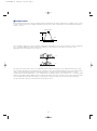 9
9
-
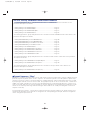 10
10
-
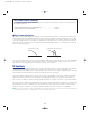 11
11
-
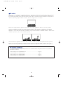 12
12
-
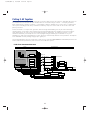 13
13
-
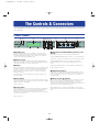 14
14
-
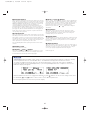 15
15
-
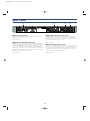 16
16
-
 17
17
-
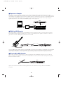 18
18
-
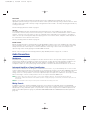 19
19
-
 20
20
-
 21
21
-
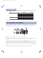 22
22
-
 23
23
-
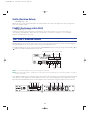 24
24
-
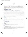 25
25
-
 26
26
-
 27
27
-
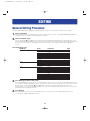 28
28
-
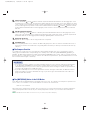 29
29
-
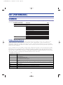 30
30
-
 31
31
-
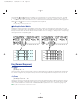 32
32
-
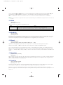 33
33
-
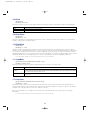 34
34
-
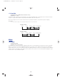 35
35
-
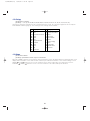 36
36
-
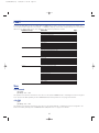 37
37
-
 38
38
-
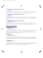 39
39
-
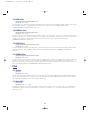 40
40
-
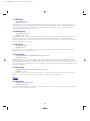 41
41
-
 42
42
-
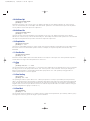 43
43
-
 44
44
-
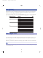 45
45
-
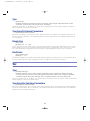 46
46
-
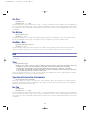 47
47
-
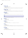 48
48
-
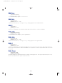 49
49
-
 50
50
-
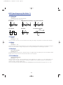 51
51
-
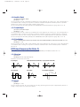 52
52
-
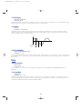 53
53
-
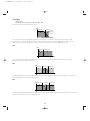 54
54
-
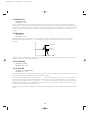 55
55
-
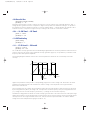 56
56
-
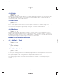 57
57
-
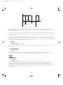 58
58
-
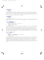 59
59
-
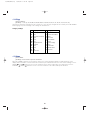 60
60
-
 61
61
-
 62
62
-
 63
63
-
 64
64
-
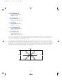 65
65
-
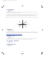 66
66
-
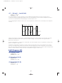 67
67
-
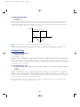 68
68
-
 69
69
-
 70
70
-
 71
71
-
 72
72
-
 73
73
-
 74
74
-
 75
75
-
 76
76
-
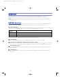 77
77
-
 78
78
-
 79
79
-
 80
80
-
 81
81
-
 82
82
-
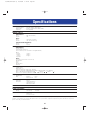 83
83
-
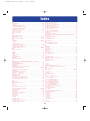 84
84
-
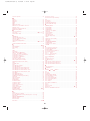 85
85
-
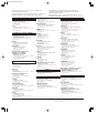 86
86
-
 87
87
-
 88
88


Yamaha FS1R El manual del propietario
- Categoría
- Instrumentos musicales
- Tipo
- El manual del propietario
en otros idiomas
- français: Yamaha FS1R Le manuel du propriétaire
- italiano: Yamaha FS1R Manuale del proprietario
- English: Yamaha FS1R Owner's manual
- Deutsch: Yamaha FS1R Bedienungsanleitung
- русский: Yamaha FS1R Инструкция по применению
- Nederlands: Yamaha FS1R de handleiding
- português: Yamaha FS1R Manual do proprietário
- dansk: Yamaha FS1R Brugervejledning
- polski: Yamaha FS1R Instrukcja obsługi
- čeština: Yamaha FS1R Návod k obsluze
- svenska: Yamaha FS1R Bruksanvisning
- Türkçe: Yamaha FS1R El kitabı
- suomi: Yamaha FS1R Omistajan opas
- română: Yamaha FS1R Manualul proprietarului
Artículos relacionados
-
Yamaha EX5R Manual de usuario
-
-
-
-
-
-
Yamaha PLG150-VL Manual de usuario
-
-
-