Craftsman 919165381 El manual del propietario
- Categoría
- Compresores de aire
- Tipo
- El manual del propietario

PermanentJy Lubricated
PortabJe
AIR COMPRESSOR
o
o
o
o
o
o
o
Safety Guidelines
Assembly
Operation
Maintenance
Service and Adjustments
Repair Parts
CAUTION: Read the Safety Guidelines
and AtI hstructions Carefully Before
Operating.
Sears, Roebuck and Co., Hoffman Estates, IL 60179 U.S.A.
Visit our Craftsman website: www°sears°com/craftsman
A08596 R_v.1 2JsJ0._

WARRANTY ................................................ 2
SPECiFiCATiON CHART ..................................... 3
SAFETY GUiDELiNES ...................................... 4-8
GLOSSARY ................................................ 9
ACCESSORIES ............................................ 9
DUTY CYCLE .............................................. 9
iNSTALLATiON ......................................... 10-11
OPERATION ........................................... 12-14
MAINTENANCE ............................................ 15
SERVICE AND ADJUSTMENTS ............................ 16-17
STORAGE ................................................ 18
TROUBLESHOOTING GUIDE ............................. 19-21
REPAIR PARTS ......................................... 22-25
ESPA_IOL .............................................. 26-45
NOTES/NOTAS ......................................... 46-47
HOW TO ORDER REPAIR PARTS ...................... back cover
FULL ONE YEAR WARRANTY AIR COMPRESSOR
If this air compressor fails due to a defect in material or workmanship within
one year from the date of purchase, RETURN IT TO THE NEAREST SEARS
REPAIR CENTER THROUGHOUT THE UNITED STATES AND SEARS WILL
REPAIR IT,FREE OF CHARGE. If purchased from Orchard Supply Hardware,
return to the nearest Orchard Store and Orchard wilI repair it, free of charge.
If this air compressor is used for commercial or rental purposes, the warranty
will apply for ninety days from the date of purchase.
This warranty gives you specific legal rights and you may have other rights
which vary from state to state.
Sears, Roebuck and Co., Dept. 817WA, Hoffman Estates, IL 60179
A08596 2= ENG

' " , O m ± ( )(h,
ModeB No. 919-165381
Running Horsepower 1.0
Bore 2-7/8"
Stroke 1-1/4"
Voltage-Single Phase 120V
Minimum Branch Circuit Requirement 15 amps
Fuse Type Time Delay
Air Tank Capacity 6
Approx. Cut-In 120
Approx. Cut-out 150
SCFM @ 40 psig 3.7
SCFM @ 90 psig 2.6
Refer to Glossary for abbreviations.
. N
ii
This manual contains information that is important for you to know and
understand. This information relates to protecting YOUR SAFETY and
PREVENTING EQUIPMENT PROBLEMS. To help you recognize this
information, we use the symbols below. Please read the manual and pay
attention to these sections.
Indicates an
imminently hazardous
)situation which, if not avoided, will
result in death or serious in'UL_[yo
Indicates a potentially
hazardous situation
which, if not avoided, coamd result in
death or serious injury..
Indicates a potentially
hazardous situation
which, if not avoided, _ result in
minor or moderate in'ujury.
Used without the
safety alert symbol
indicates a potentially hazardous
situation which, if not avoided, may
result in _ge.
)
Some dust created by power sanding, sawing, grinding, drilling, and
other construction activities contains chemicals known (to the State of
California) to cause cancer, birth defects or other reproductive harm. Some example of
these chemicals are:
" lead from lead-based paints
" crystalline silica from bricks and cement and other masonry products
® arsenic and chromium from chemically-treated lumber
Your risk from these exposures varies, depending on how often you do this type of work.
To reduce your exposure to these chemicals: work in a well ventilated area, and work
with approved safety equipment, always wear MSHA/NIOSH approved, properly fitting
face mask or respirator when using such tools.
When using air tools, basic safety precautions should always be followed to reduce the
risk of personal injury.
3- ENG A08596

Save these instructions
Improper operation or maintenance of this product could result in serious injury and
property damage. Read and understand all warnings and operation instructions before
using this equipment.
WARNING: Risk of e×p_osion or fire _,i
What Could Happen
It is normal for emectricaR contacts
within the motor and pressure switch to
spark.
If electrical sparks from compressor
come into contact with flammable
vapors, they may ignite, causing fire or
e×plosion.
Restricting any of the compressor
ventilation openings will cause serious
overheating and could cause fire.
Unattended operation of this product
could result in personal injury or
property damage. To reduce the risk
of fire, do not allow the compressor to
operate unattended.
How To Prevent Jt
Always operate the compressor in a
well ventilated area free of combustible
matedams, gasoline, or solvent vapors.
Jf spraying flammable materials, locate
compressor at least 20 feet away from
spray area. An additional length of hose
may be required.
Store flammable materials in a secure
location away from compressor.
Never place objects against or on top
of compressor. Operate compressor
in an open area at least 12 inches
away from any wall or obstruction that
would restrict the flow of fresh air to the
ventilation openings.
Operate compressor in a clean, dry well
ventilated area. Do not operate unit
indoors or in any confined area.
Amways remain in attendance with the
)roduct when it is operating.
ABways disconnect eRectrical power by
moving pressure switch lever to the off
;osition and drain tank daily or after
each use,
A08596 4-ENG

111¸¸ D 11!1
iiiiiiiii_, III!
WARNING: Risk of Bursting
Air Tank: The following conditions could lead to a weakening of the tank, and result
in a violent tank explosion and could cause property damage or serious injury.
What Coumd Nal2pen
Failure to properly drain condensed
water from tank, causing rust and
thinning of the steer tank.
Modifications or attempted repairs to
the tank.
Unauthorized modifications to the
unRoader valve, safety vaBve, or any
other components which controm tank
. pressure.
Excessive vibration can weaken the
air tank and cause rupture or
expBosion
ATTACHMENTS & ACCESSORIESr
Exceeding the pressure rating of
air tooms, spray guns, air operated
accessories, tires, and other inflatables
can cause them to explode or fly apart,
and could result in serious injury.
How To Prevent It
Drain tank dally or after each use.
If tank develops a leak, replace it
immediately with a new tank or replace
the entire compressor.
Never drill into, weld, or make any
modifications to the tank or its
attachments.
The tank is designed to withstand specific
operating pressures. Never make
adjustments or parts substitutions
to aBter the factory set operating
pressures,
For essential control of air pressure,
you must install a pressure regulator
and pressure gauge to the air outmet
{if not equipped) of your compressor.
Follow the equipment manufacturers
recommendation and never exceed the
maximum allowable pressure rating of
attachments. Never use compressor
to inflate small low pressure objects
such as children's toys, footballs,
basketballs, etc.
WARNING: Risk from Flying Objects
What Coumd Happen How To Prevent It
The compressed air stream can cause
soft tissue damage to exposed skin
and can propel dirt, chips, Boose
particles, and small objects at high
speed, resulting in property damage or
personal injury.
Always wear ANSi Z87.1 approved safety
glasses with side shieMs when using the
compressor
Never point any nozzBe or sprayer
toward any part of the body or at other
people or animals.
Always turn the compressor off and
bBeed pressure from the air hose and tank
before attempting maintenance, attaching
tools or accessories.
5-ENG A08596

WARNING: Risk of Electrical Shock
What Ceumd Happen
Your air compressor is powered by
electricity. Like any other electrically
powered device, If it is not used
properly it may cause electric shock.
Repairs attempted by unqualified
personnel can result in serious injury
or death by electrocution.
Electrical Grounding: Failure to provide
adequate grounding to this product
could result in serious injury or death
from electrocution.
See grounding instructions.
Now To Prevent mt
Never operate the compressor outdoors
when it is raining or in wet conditions.
Never operate compressor with
protective covers removed or damaged.
Any emectrical wiring or repairs required
on this product should be performed by
authorized service center personneB
in accordance with national and local
electrical codes.
Make certain that the electrical circuit
to which the compressor is connected
provides proper eBectrical grounding,
correct voltage and adequate fuse
protection.
WARNING: Risk to Breathing
What Could
The compressed air directly from your
compressor is not safe for breathing.
The air stream may contain carbon
monoxide, toxic vapors, or solid
particles from the tank. Breathing these
contaminants can cause serious injury
or death.
Sprayed materials such as paint, paint
solvents, paint remover, insecticides,
weed killers, may contain harmful
vapors and poisons.
Now To Prevent It
Air obtained directly from the compressor
should never be used to supply air for
human consumption. In order to use air
_roduced by this compressor for breathing,
suitable filters and in-line safety'
equipment must be property installed.
In-line filters and safety equipment
used in conjunction with the compressor
must be capable of treating air to aH
applicable local and federal codes prior
to human consumption.
Work in an area with good cross
ventilation. Read and follow the safety
instructions provided on the label or
safety data sheets for the materials
you are spraying. Use a NIOSN/MSNA
approved respirator designed for use with
your specific application.
A08596 6-ENG

WARNING: Risk of Burns
What Could Hap___en
Touching exposed metal such as the
compressor head or outlet tubes, can
result in serious burns.
Now To Prevent It
Never touch any exposed metal parts
on compressor during or immediately
after operation. Compressor win remain
hot for several minutes after operation.
Do not reach around protective shrouds
or attempt maintenance until unit has
been allowed to cool
iiiiiii_, b
WARNING: Risk from Moving Parts
What Could Happen
Moving parts such as the pulley, flywheel,
and belt can cause serious injury if
they come into contact with you or your
clothing.
Attempting to operate compressor with
damaged or missing parts or attempting
to repair compressor with protective
shrouds removed can expose you to
moving parts and can result in serious
injury.
How To Prevent It
Never operate the compressor with
guards or covers which are damaged or
removed.
Any repairs required on this product
should be performed by authorized
service center personnel
WARNING: Risk of Falling
What Could Happen
A portable compressor can fan from
a table, workbench, or roof causing
damage to the compressor and could
result in serious injury or death to the
operator.
How To Prevent mt
Always operate compressor in a stable
secure position to prevent accidental
movement of the unit. Never operate
compressor on a roof or other elevated
position. Use additionam air hose to
reach high locations.
7- ENG A08596

WARNING: Risk of Serious Injury or Property Damage When _]
Transporting Compressor
(Fire, Inhalation, Damage to Vehicle Surfaces)
What Could Happen
Oil can leak or spill and could result
in fire or breathing hazard; serious
injury or death can result, oil leaks will
damage carpet, paint or other surfaces
in vehicles or trailers.
How To Prevent it
Always pBace COMPRESSOR on a
protective mat when transporting to
protect against damage to vehicle from
leaks. Remove COMPRESSOR from
vehicle immediately upon arrival at your
destination.
_D
WARNING: Risk of Unsafe Operation
What Could Happen ........
Unsafe operation of your air compressor
could lead to serious injury or death to
you or others.
How To Prevent mt
Review and understand all instructions
and warnings in this manual.
Become famiRiar with the operation and
controBs of the air compressor.
Keep operating area dear of all persons,
pets, and obstacles.
Keep children away from the air
compressor at aH times.
Do not operate the product when
fatigued or under the influence of
alcohol or drugs. Stay alert at aH times.
Never defeat the safety features of this
product.
Equip area of operation with a fire
extinguisher.
Do not operate machine with missing,
broken, or unauthorized parts.
SAVE THESE mNSTRUCTmONS
A08596 8- ENG

Become familiar with these terms When the tank pressure drops to a
before operating the unit. certain low level the motor will restart
OFM: Cubic feet per minute, automatically. The low pressure
SCFM: Standard cubic feet per at which the motor automatically
minute; a unit of measure of air restarts is called "cut-in" pressure.
delivery. Cut-Out Pressure: When an air
PSi@: Pounds per square inch compressor is turned on and begins
gauge; a unit of measure of pressure, to run, air pressure in the air tank
Cede Certification: Products that begins to build. It builds to a certain
bear one or more of the following high pressure before the motor
marks: UL, CUL, ETL, CETL, have automatically shuts off, protecting
been evaluated by OSHA certified your air tank from pressure higher
independent safety Jaboratories and than its capacity. The high pressure
meet the applicable Underwriters at which the motor shuts off is called
Laboratories Standards for Safety. "cut-out" pressure.
Cut-In Pressure: While the motor Branch Circuit: Circuit carrying
electricity from electrical panel to
is off, air tank pressure drops as outlet.
you continue to use your accessory.
This unit is capable of powering the following Accessories. The accessories are
available through the current Power and Hand Tool Catalog or full-line Sears
stores.
Accessories
® In Line Filter
+ Tire Air Chuck
® Quick Connector Sets
(various sizes)
+ Air Pressure Regulators
+ Oil Fog Lubricators
+ Air Hose: 1/4", 3/8" OR 1/2" kD+in
various lengths
Refer to the selection chart located
on the unit to select the tools this unit
is capable of powering.
0 ll'lll It. -
This air compressor pump is
capable of running continuously.
However, to prolong the life of your
air compressor, it is recommended
that a 50%-75% average duty
cycle be maintained; that is, the air
compressor pump should not run
more than 30-45 minutes in any given
hour.
9-ENG A08596

HOW TO SET UP YOUR
UNiT
Location of the Air Compressor
Locate the air compressor in a
clean, dry and well ventilated area.
The air compressor should be
located at bast 12" away from the
wall or other obstructions that will
interfere with the flow of air. The
air compressor pump and shroud
are designed to allow for proper
cooling. The ventilation openings
on the compressor are necessary
to maintain proper operating
temperature. Do not place rags or
other containers on or near these
openings.
GROUNDING iNSTRUCTiONS
_Risk of Electrica_
Shock. in the
event of a short circuit, grounding
reduces the risk of shock by
providing an escape wire for
the electric current. This air
compressor must be properly
grounded.
The portable air compressor is
equipped with a cord having a
grounding wire with an appropriate
grounding plug (see following
illustrations), The plug must be used
with an outlet that has been installed
and grounded in accordance with all
local codes and ordinances.
1. The cord set and plug with this
unit contains a grounding pin.
This plug MUST be used with a
grounded outlet.
IMPORTANT: The outlet being used
must be installed and grounded in
accordance with aII loca! codes and
ordinances.
2. Make sure the outlet being used
has the same configuration
as the grounded plug. DO
NOT USE AN ADAPTER, See
illustration.
3. Inspect the plug and cord before
each use. Do not use if there are
signs of damage.
Grounded
Outlets
Ground/_ngPin
4.
if these grounding instructions
are not completely understood,
or if in doubt as to whether
the compressor is properly
grounded, have the installation
checked by a qualified
electrician.
grounding can result in emectricaB
shock.
Do not modify the plug provided. If
it does not fit the avaHabmeoutlet,
a correct out_et should be installed
by a qualified electrician.
Repairs to the cord set or plug
MUST be made by a qualified
electrician.
A08596 10- ENG

Extension Cords
Using extension cords is not
recommended, The use of extension
cords will cause voltage to drop
resulting in power loss to the motor
and overheating.
Attach extra air hoses at the air outlet
instead of using extension cords.
If an extension cord must be used, be
sure it is:
a 3-wire extension cord that has
a 3-blade grounding plug, and a
3-slot receptacle that will accept
the plug on the product
in good condition
no longer than 50 feet
12 gauge (AWG) or larger. (Wire
size increases as gauge number
decreases. !0 AWG and 8 AWG
may also be used. DO NOT USE
14 OR 16 AWG.)
Voltage and Circuit Protection
Refer to the Specification Chart for
the voltage and minimum branch
circuit requirements.
Certain air compressors can be
operated on a 15 amp circuit if the
following conditions are met.
1. Voltage suppiy through branch
circuit is 15 amps.
2. Circuit is not used to supply any
other electrica! needs (lights,
appliances, etc.).
3. Extension cords comply with
specifications.
4. Circuit is equipped with a
15 amp circuit breaker or 15
amp time delay fuse. NOTE: If
compressor is connected to a
circuit protected by fuses, use
only time delay fuses. Time delay
fuses should be marked "D" in
Canada and "T" in the US.
If any of the above conditions
cannot be met, or if operation of
the compressor repeatedly causes
interruption of the power, it may be
necessary to operate it from a 20
amp circuit. It is not necessary to
change the cord set.
11-ENG A08596

Know Your Air Compressor
READ THiS OWNER'S MANUAL AND SAFETY RULES BEFORE OPERATING
YOUR UNIT. Compare the illustrations with your unit to famiIiarize yourself with
the location of various controls and adjustments. Save this manual for future
reference. On/Auto/Off Switch
Description of Operation
Become familiar with these controls
before operating the unit.
On/Auto/Off Switch: Turn this switch
"ON" to provide automatic power
to the pressure switch and "OFF"
to remove power at the end of each
use.
Pressure Switch: The pressure
switch automatically starts the
motor when the air tank pressure
drops below the factory set "cut-in"
pressure, it stops the motor when the
air tank pressure reaches the factory
set "cut-out" pressure.
Safety Valve: if the pressure switch
does not shut off the air compressor
at its "cut-out" pressure setting, the
safety valve wil! protect against high
pressure by "popping out" at its
factory set pressure (slightly higher
than the pressure switch "cut-out"
setting).
Outlet Pressure Gauge: The outtet
pressure gauge indicates the air
pressure avaiIable at the outlet side
of the regulator. This pressure is
controlled by the regulator and is
always less than or equal to the tank
pressure.
Tank Pressure Gauge: The tank
pressure gauge indicates the reserve
air pressure in the tank.
Regulator: Controls the air pressure
shown on the outiet pressure gauge.
Turn the knob clockwise to increase
pressure and counterclockwise to
decrease pressure.
Drain VaBve: The drain valve is
located at the base of the air tank
and is used to drain condensation at
the end of each use.
CooBing System (not shown): This
compressor contains an advanced
design cooling system. At the heart of
this cooling system is an engineered
fan. It is perfectly normal for this fan
to blow air through the vent holes
in large amounts. You know that the
cooling system is working when air is
being expelled.
A08596 12-ENG

Air Compressor Pump (not shown}:
Compresses air into the air tank.
Working air is not available until the
compressor has raised the air tank
pressure above that required at the
air outlet.
Oheek Valve: When the air
compressor is operating, the check
valve is "open", allowing compressed
air to enter the air tank. When the
air compressor reaches "cut-out"
pressure, the check valve "closes",
allowing air pressure to remain inside
the air tank.
Check Valve
How to Use Your Unit
Bow to Stop:
1. Set the On/Auto/Off lever to
"OFF".
Before First Start Up
damage may resumt if the following
breakqn instructions are not
emoseByfolmowed°
This procedure is required before the
air compressor is put into service and
when the check valve or a complete
compressor pump has been replaced.
1. Make sure the On/Auto/Off lever
is in the "OFF" position.
2. Plug the power cord into the
correct branch circuit receptacle.
(Refer to Voltage and Circuit
Protection paragraph in the
Insta!Iation section of this
manual.)
3. Open the drain valve (counter-
clockwise) fully to permit air to
escape and prevent air pressure
build up in the air tank during the
break-in period.
4. Move the On/Auto/Off lever
to "ON/AUTO" position. The
compressor will start.
5. Run the compressor for 15
minutes. Make sure the drain
valve is open and there is
minimal air pressure build-up in
tank.
6. After 15 minutes, close the drain
valve by turning c!ockwise. The
air receiver wilI fill to "cut-out"
pressure and the motor will
stop.
The compressor is now ready for use.
13-ENG A08596

Before Each Start-Up:
1. Place On/Auto/Off lever to
"OFF".
2. Turn the regulator knob counter-
clockwise to set the outlet
pressure to zero.
3. Attach hose and accessories.
NOTE: The hose or accessory wil!
require a quick connect plug if the
air outlet is equipped with a quick
connect socket.
Bow to Start:
1. Turn the On/Auto/Off lever to
"AUTO" and allow tank pressure
to build, Motor wilI stop when
tank pressure reaches "cut-out"
pressure.
2. Turn regulator knob clockwise to
increase pressure and stop when
desired pressure is reached.
The compressor is ready for use.
pressure causes a hazardous
risk of bursting, Check the
manufacturer's maximum pressure
rating for air tooms and accessories,
The regulator outlet pressure
must never exceed the maximum
pressure rating,
A08596 14-ENG

Customer Responsibilities
Before Daily
each or after
each
use
use
3heck Safety VaLve
:::)rainTank
O
O
cycles automaticamly when power
is on, When servicing, you may
be exposed to voltage sources,
compressed air, or moving parts,
Before servicing unit unpmug or
disconnect emectricamsuppmy to
the air compressor, bleed tank
of pressure, and allow the air
compressor to cool
NOTE: See "Operation" section for
the location of controls.
To Check Safety Valve
does not work properly, over_
pressurization may occur, causing
air tank rupture or an expBosion.
1. Before starting compressor, pull
the ring on the safety valve to
make sure that the safety valve
operates freely. If the valve
is stuck or does not operate
smoothly, it must be replaced
with the same type of vaive.
To Drain Tank
1_ Set the On/Auto/Off lever to
"OFF".
2. Turn the regulator knob counter-
clockwise to set the outlet
pressure to zero.
3. Remove the air toot or accessory.
4. PulI ring on safety valve alIowing
air to bIeed from the tank until
tank pressure is approximately
20 psi. Release safety valve ring.
5. Drain water from air tank by
opening drain valve on bottom of
tank.
_ Water will
condense in the
air tank, If not drained, water will
corrode and weaken the air tank
causing a risk of air tank rupture,
6. After the water has been drained,
cIose the drain valve. The air
compressor can now be stored.
NOTE: If drain valve is plugged,
release all air pressure. The valve
can then be removed, cleaned, the
reinstalled.
15- ENG A08596

ALL MAINTENANCE AND REPAIR
OPERATIONS NOT LISTED MUST
BE PERFORMED BY A TRAmNED
SERVmCE TECHNmCmAN°
cycmee automaticamly when power
is on, When servicing, you may
be exposed to voltage sources,
compressed air, or moving parts,
Before serv{cing unit unplug or
disconnect electricam supply to
the air compressor, bleed tank
of pressure, and allow the air
compressor to cool
To Replace or Clean Check
Valve
1. Release all air pressure from air
tank. See "To Drain Tank" in the
Maintenance section.
2. Set the On/Auto/Off lever to
"OFF" and unpiug unit.
3. Remove the hose by removing
the hose damp.
NOTE: The hose clamp is not
reusable. You must purchase a
new hose clamp, see the Parts List
Manual or purchase a standard hose
clamp at a local hardware store.
5. Unscrew the check valve (turn
counterclockwise) using a socket
wrench.
6. Make sure the valve disc moves
freely inside the check valve
and the spring holds the disc in
the upper, closed position. The
check valve may be cleaned
with a solvent, such as paint and
varnish removeK
7. Apply sealant to the check valve
threads. Reinstall the check valve
(turn clockwise).
8. Replace hose and new hose
clamp.
9. Perform the Break-in Procedure.
See "Break-in Procedure" in the
Operation section.
Hose Clamp
Cheek
Vamve
A08596 16-ENG

To Replace Regulator
1. Release alI air pressure from air
tank, See "To Drain Tank" in the
Maintenance section.
2. Unplug unit.
3. Using an adjustable wrench
remove the outlet pressure gauge
and quick connect from the
regulator,
4. Remove the regulator.
5. Apply pipe sealant tape to the
nipple on the standpipe,
6. Assemble the regulator and
orient as shown.
NOTE: Arrow indicates flow of
air. Make sure it is pointing in the
direction of air flow.
Reapply pipe sealant to outIet
pressure gauge and quick
connect.
Reassemble outtet pressure
gauge and quick connect. Orient
outlet pressure gauge to read
correctly. Tighten connect with
wrench.
17-ENG A08596

Before you store the air compressor,
make sure you do the following:
1. Review the "Maintenance"
section on the preceding
pages and perform scheduled
maintenance as necessary.
2. Set the On/Auto/Off lever to
"OFF".
3. Turn the regulator
counterclockwise and set the
outlet pressure to zero.
4. Remove the air toot or accessory.
5. Pull ring on safety valve allowing
air to bleed from the tank until
tank pressure is approximately
20 psi. Release safety valve ring.
6. Drain water from air tank by
opening drain valve on bottom of
tank.
_ Water will
condense in the
air tank, If not drained, water will
corrode and weaken the air tank
causing a risk of air tank rupture,
7. After the water has been drained,
close the drain or drain valve.
NOTE: If drain valve is plugged,
release all air pressure. The valve
can then be removed, cleaned, then
reinstalled.
8. Protect the electrica! cord and
air hose from damage (such as
being stepped on or run over).
Store the air compressor in a clean
and dry location.
A08596 18-ENG

11! _ • _ m Q _ _ _ "1_
iiiiiiiiii_.... c' iL
_ Performing repairs may expose vomtage sources, mov{ng
parts or compressed air sources, moving parts or
compressed air sources. Personal injury may occur. Prior to attempting
any repairs, unplug the air compressor and bmeedoff all air tank air
pressure.
PROBLEM
Excessive tank
pressure - safety
valve pops off.
Air leaks at
fittings.
Air ieaks in air
CAUSE
Pressure switch does
not shut off motor when
compressor reaches "cut-
out" pressure.
Pressure switch "cut-out"
too high.
Tube fittings are not tight
enough.
Defective air tank.
tank or at air
tank welds.
Air leaks Leaking seal.
between head
and valve plate,
Air ieak from
safety valve.
Possible defect in safety
valve.
Possible defect in safety
valve.
Knocking Noise.
CORRECTION
Move On/Auto/Off lever
to the "OFF" position, if
the outfit does not shut off
contact a Trained Service
Technician.
Contact a Trained Service
Technician.
Tighten fittings where air
can be heard escaping.
Check fittings with soapy
water solution. Do Not
Overtighten,
Air tank must be replaced.
Do not repair the leak.
weld or otherwise modify
air tank or it will weaken.
The tank can rupture or
expmode.
Contact a Trained Service
Technician.
Operate safety valve
manualiy by pulling on ring.
if valve still leaks, it should
be replaced.
Operate safety valve
manually by pulling on ring.
if vaIve stiIl leaks, it shouId
be replaced.
19-ENG A08596

PROBLEM
Pressure reading
on the regulated
pressure gauge
drops when an
accessory is
used.
CAUSE
It is normal for "some"
pressure drop to occur.
Prolonged excessive use of
air.
Compressor is
not supplying
enough air
to operate
accessories.
Regulator knob
has continuous
air leak.
Regulator will
not shut off air
outlet.
Compressor is not large
enough for air requirement.
Hole in hose.
Check valve restricted.
Air leaks.
Damaged regulator.
Damaged regulator.
CORRECTION
If there is an excessive
amount of pressure drop
when the accessory is used,
adjust the regulator following
the instructions in the
"Description of Operation"
paragraph in the "Operation
Section.
NOTE: Adjust the regulated
pressure under flow
conditions (while accessory is
bein, used.
Decrease amount of air
usage.
Check the accessory
air requirement. If it is
higher than the SCFM or
pressuresuppliedby your
air compressor, you need a
larger compressor.
Check and replace if
required.
Remove and clean, or
replace.
Tighten fittings.
Replace.
Replace.
A08596 20-ENG

PROBLEM
Motor will not
run.
CAUSE
Fuse blown, circuit breaker
tripped.
Extension cord is wrong
length or gauge.
Loose electrical
connections.
Faulty motor.
CORRECTION
Check fuse box for blown
fuse and replace as
necessary. Reset circuit
breaker. Do not use a fuse
or circuit breaker with higher
rating than that specified for
your particular branch circuit.
Check for proper fuse. You
should use a time delay fuse.
Check for low voltage
problem.
Check the extension cord.
Disconnect the other
electrical appliances from
circuit or operate the
compressor on its own
branch circuit.
Check the extension cord.
Check wiring connection
inside terminal box.
Have checked by a Trained
Service Technician.
21-ENG A08596

Air Compressor Model Number 919o165381
2_
Torqueto 10_20inqbs 3_
A08596 22- ENG

Air Compressor Model Number 919o165381
KEY
NO. PART NUMBER DESCRIPTION
1 Z-D26909 Tank
2 SST-5314-1 Recess Rubber Bumper (3)
3 9! 895680 Screw (3)
4 SSF-621 Screw (2)
5 D30198 Nipple, 1/4-18 NPT X 2-1/2
7 A06891 Drain Valve
8 D20114 Safety Valve
9 CAC-4296-1 Regulator
10 D20675 Quick Connect 1/4 NPT
11 Z-A07456 Gauge
12 SS-2071 Nipple, 1/4-18 NPT X 1-1/2
14 SSP-6021 Bushing Reducer 1/8-1/4NPT
15 Z-D27226 Pressure Switch
18 D27022 Check Valve
19 CAC-1254 Pump Isolator (4)
20 + ......... Pump Assembly
21 CAC-1206-1 Hose Clamp
24 LA-3109 Label, Drain Tank Eng/Spa
26 D26618 Power Cord
28 LA-3108 Label, Hot Surface
33 D30075 Label, Sears Performance
34 D21921 Label, Star Rating #3
35 Z-A07467 Gauge
+ order individual parts, see pump diagram
23-ENG A08596

Air Compressor Model Number 919o165381
2
J
17
Torque
30-45in.-Ibs.
14
1
./
9-12
9-13 Torque
49-55in.qbs.
20
@ '% _- 4 Torque
handtight
5 10in.-Ibs.Max
18
\
19
A08596 24-ENG

Air Compressor Model Number 919o165381
KEY
NO. PART NUMBER DESCRiPTiON
1 CAC-1320 Shroud (left)
2 D25735 Shroud (right)
3 D25877 Head
4 ÷ CAC-1212 Tube Seal
5 D22253 Outlet Tube
6 ÷ Z-D24819 Head Gasket
7 Z-A08548 Valve Plate Assembly
8 ÷ ......... Gasket
9 Z-A04615 Sub Pump Assembly
9-8 > Rod Assembly
9-9 + Pre-Formed Compression Ring
9-10 ......... Connecting Rod Cap
9-11 + D21127 Screw #10-24
9-12 x SSF-3147 Screw, 3/8-16 UNC Socket Head
9-13 + > Cylinder Sleeve
13 x SUDL-9-1 Screw, #8-32
14 D25731 Pump Isolator (5 used)
15 x SSF-995 Washer Screws 10-24 x 7/8 (4 used)
17 D27279 Motor Cord
18 CAC-1206-1 Hose Clamp
19 H-7051 Hose 1/4 ID x 10" Length
20 x SSF-3156 Screw, 10-9 X 1/2 Plastite (5 used)
21 ** -......... Motor Brush Replacement
23 A00470 Support Handle
24 AC-0815 Timing Belt
Not Illustrated
LA-3270
A08596
D20598
D21109
9-18173
H-7048
AC-0625
Label, Warning Eng/Span
Operators Manual
Quick Connect Plug, Female
Quick Connect Body, Female
Nailer ! - !/4" Brad Magnesium
Air Hose 3/8" x 25'
Sealant Tape
Availabme Kits
x KK-4929 Fastener Kit
> KK-4964 Connecting Rod Kit
+ D30324 Ring Kit
÷ D30139 Gasket and Sea! Kit
** REPLACEMENT BRUSHES FOR MOTOR
Motor number and vendor is stamped on motor stack. Both must be
identified before ordering replacement brush. Motor part number for
reference only= Motor not available for service=
Motor Vendor
M0-9088 Northland
D23494 GS Electric (Ametek)
D27098 GS Electric (Ametek)
D27098 ECM (Gold Tuning)
D27219 GS Electric (Ametek)
Brush Set
Z-D20041
Z-D23825
Z-D23825
Z-D27196
Z-D23825
25= ENG A08596

GARANTiA TOTAL DE UN ANO DEL OOMPRESOR DE AIRE
Si este compresor de aire Craftsman fallase debido a defectos de materiales
o de fabricaci6n dentro del aho de su fecha de compra, Sears, a su opci6n,
Io reparara o reemplazara sin costo alguno. Comunfquese con el Centre
de Servicio Sears mas cercano (1-800-4-MY-HOME) para coordinar su
reparaciOn, o devuelva el compresor de aire al lugar donde Io compr6 para
que Io cambien.
Si este compresor de aire se usase con fines comemiales o para alquiler, esta
garantia se aplica s61o durante los primeros noventa dias a partir de su fecha
de compra=
Esta garantia ie otorga derechos especfficos y usted podria tener otros
derechos que varian de un estado a otro.
Sears, Roebuck and Co., Dept. 817WA, Hoffman Estates, IL 60179
A08596 26= SP

Modelo N°
Potencia de trabajo
Di_metro interior
Carrera
Tensi6n monof_sica
Circuito minimo requerido
Tipo de fusibleAcci6n retardada
Capacidad de aire en el tanque
Presi6n de corte de entrada
Presi6n de corte de salida
SCFM a 40 psig
SCFM a 90 psig
919-165370
1,0
2,875 pulg. (73.0 mm)
1,25 pulg. (31,8 ram)
120V
15A
6 Galones (22,7 litros)
120
150
3,7 Calibre de libras
pot pulgada cuadrada
2,6 Calibre de libras
por pulgada cuadrada
Refi6rase al glosario para descifrar las abreviaturas.
Este manual contiene importante informaci6n para que usted sepa y comprenda. Dicha
informaci6n se relaciona con la protecci6n de SU SEGURIDAD Y LA PREVENCION DE
PROBLEMAS AL EQUIPO. Para ayudarlo a reconocer esa informaci6n, utilizamos los
s[mbolos indicados m_s abajo. S[rvase leer el manual y prestar atenei6n a diehos
s_mbolos.
Indica una situaci6n
de inminente riesgo, la
cual, si no es evitada, eausar_ la muerte
o lesiones serias.
Indica una
situaci6n
potencialmente riesgosa, que si no es
evitada, 9odr[a resultar en la muerte o
i lesiones serias.
Indica una situaci6n
potencialmente
peligrosa, la cual, si no es evitada, podr[a
resultar en lesiones menores o
moderadas.
Usado sin el sfmbolo
de seguridad de
alerta indica una situaci6n potencialmente
riesgosa la que, si no es evitada, podda
causar da_ios en la _iedad.
Algunos tipos de aserdn creados per maquinas el_ctricas de Iijado, aserrado,
amolado, perforado u otras actividades de la construcci6n, contienen materiales
qu[micos conocidos (en el Estado de California) como causantes de cancer, defectos de nacimiento u otros
da_os del aparato reproductivo_ Algunos ejemplos de dichos productos qu[micos son:
El p_omo contenido en algunas pinturss con base de p_omo
Si_ice cristalizado proveniente de los ladriHos, e_ cemento y otros productos de a_ba[iileria
Ars&nico y creme provenientes del tratamiento qu[mico dado a la madera
Su riesgo a dichas exposiciones variara dependiendo de la frecuencia con la que usted realice
diferentes tipos de traba}o, Para reducir su exposici6n a _aacci6n de dichos agentes qu[micos:
trsbaje en zonas bien ventiladas, y h_ga_o con equipo de seguddad aprobado, use siempre protecci6n
facial o respirador MSHA / NIOSH aprobados cuando deba utilizar dichas herramientas
AI utilizar herramientas neum&ticas tambien deben tomarse precauciones basicas de seguridad, a fin
de reducir la posibiWad de riesgo de lesiones personales,
27- SP A08596

GUARDE ESTAS |NSTRUCCiONES
La operaci6n o el mantenimiento inadecuados de este producto podrian ocasionar
serias lesiones y dafios a la propiedad= Lea y comprenda todas las advertencias e
instrucciones de funcionamiento antes de utilizar este equipo=
iiii" _
ADVERTENCIA: Riesgo de Explosidn o mncendio
qu_ puede occurrir
Para los contactos eU_ctricos es normal la
e×istencia de cHspas entre e_ motor y el
interruptor a presi6n.
Si las cMspas electricas provenientes del
compresor tomaran contacto con
emanaciones de materiaies ieflamabUes,
eHos podrian arder orig#_ando #_cendio o
explosi6n,
Restringir cualquiera de _as aberturas de
ventilaci6n causara un serio recaUentamiento
y podr_a producir un incendio.
Dejar desatenido este producto mientras
el mismo esta en funcionamiento puede
resuUtar en {esiones persona{es o daSos
a Uapropiedad. Rata reducir el riesgo de
incendio, no permita que e{ compresor opere
desatendido.
c6mo preveniHo
Opere siempre eUcompresor en un sector bisn
ventitado y Hbre de materiales eombustiMes,
gasomina o emanaciones de somvente.
En un area de rociado de materia_es inflamables,
ubique al compresor per Io menos a 6,1m (20
pies) de distancia deU _rea de rociado. Podria
requerirse una extensidn de la manguera.
Almacene los materiaUes irfflamables en una
ubicaci6n segura, aUejados deU compresor.
Jam_s coloque objetos apoyados o sobre e8
compresor. Opere el compresor en un sector
abierto, por Io menos a 30 cm (12 puUgadas)
alejado de cua_quier pared u obstrucci6n que
restrinia el fluio de aire fresco alas aberturas de
ventilaci6n=
Opere e_compresor en un sector Hmpio, seco, y
bien venti_ado. No opere la unidad en espacios
cerrados o euaUquier _rea confinada.
Mantengase siempre aUer_a cada vez que eU
producto este funcionando,
Desconecte siempre eBsuministro el_ctrico
moviendo Ua palanca conrnutadora de presi6n
a Ua posici6n de apagado (off), y drene e_
tanque diariamente o despu_s de carla use.
A08596 28- SP

ADVERTENCIA: Riesgo de ExpRosi6n _l
Tanque de aire: las siguientes condiciones podr[an, causar el debilitamiento del tanque, y
determinar su explosi6n violenta, danes a la propiedad o serias lesiones=
qu_ puede occurrir
Drenaje hradecuado del agua condensada
en e8 tanque, siende la causa de_ 6×ide que
reduce el espesor del tanque de acero.
Modificaciones o intento de reparaciones al
tanque.
Modificaciones Me autorizadas a la v_lvuUa
de descarga, v_lvuUa de eeguridad o cualquier
otto componente que controUe la
presi6n del tanque.
La vibraci6n e×cesiva puede debiHtar
el tanque de aire y causar su ruptura o
expiosi6n.
AGREGADOS Y ACCESOR/OS
El e×ceso a Uos vaUores de presi6n estabUeci-
doe para Uas herramientas neurnaticas, pistolas
rociadoras, accesorios activados per airs, cubi-
ertas y otros obietos inflames, puede causar su
e×plosi6n o ser arrojados, pudiendo ocasionar
sedas lesiones,
c6rno preveniHo
Drene eUtanque diariamente o despu_,s de
cada use, Si el tanque genera una perdida,
reemplacelo inmediatamente con un nuevo
tanque o reemplace e_ compresor complete,
Jarnas perfore, suelde, o efectQe rnodificaci6n
alguna al tanque o sus accesorios.
E_tanque esta dise_ado para r÷sistir presiones
operativas especificas. Jam_s efectQe ajustes o
sustituya partes que aUteren Uas reguUaciones
de presi6n origir_ales de f_brica.
Para un control esencial de la presbn, debe usted
instalar un reguhdor y un medidor de presi6n
a la salida del airs de su compresor. (Si no
estuviese equipado) Siga las recomendaciones de
bs fabricantes de su equipo y jamas exceda los
valores maximos de presion permitidos para los
accesorios. Jarn_s use el cornpresor para infUar
ob]etos que requieren poca o baja presi6n,
taUes come juguetes para los ni_oe, peUotas de
fQtboU, pelotas de basquet, etc.
]
€ ii,
ADVERTENCIA: Riesgo de Objetos Arrojados per el Airs
qu# puede occurrir c6rno preveniHo
El chorro de aire comprimido puede causar
dafios sobre los tejidos blandos de la piel
e×puesta, y puede propuUsar suciedad, astillas,
particuUas sueUtas y peque_os objetos a aUta
veUocidad, ocasionando dafios a la propiedad o
lesiones personales.
AI utilizar el compresor, use siernpre anteojos
de seguridad ANSi Z87.1 aprobados, con
protecci6n UateraL
Jamas apunte ninguna boquiHa o pulverizador
hacia partes de_ cuerpo, a otras personas o
anirnales.
Apague siempre el compresor y purgue _a
presi6n de la manguera del affe y de_ tanque,
antes de intentar e! mantenimiento, e_ acop_e de
herranlientas o accesorios.
29-SP A08596

ADVERTENCIA: Riesgo de Descarga El_ctrica I _.._ i
qu6 puede occurrir c6mo preveniHo
Su compresor de aire est& accionado per Jam&e oper_ el compresor a la intemperie
electricidad. Come cualquier otto dispositivo cuando est& Iloviendo o en condiciones de
e_6ctrico irnpulsado electdcamente, si no se Io humedad.Nunca opere el cornpreeor sin sus
utiliza adecaadarnente, podr_a cauearle una defensas o sas cubiertas removidas o
desearga ei_ctriea, dafiadas.
Lae reparacionee intentadas per personal [lo
caHfieado podr_an ocasionar serias lesiones o
Ua rnue_te per eUeetrocuci6n,
CONEXION A TERRA: Dejar de proveer una
adecaada cone×i6n a tierra a este producto
podria ocasionar Uesiones serias o la rnuerte
per eBectrocuci6m Vet instrucciones para la
puesta a tierra.
Cualquier cone×i6n eU_ctrica o reparaci6n
requerida per este produeto debe eer
efectuada po_ personal auto_izado de Uos
servieentros de acuerdo a los c6digos el_ctricos
naciona_es y locales.
Aseg_rese que el circuito el_ctrico a{ cual esta
conectado el compresor, euministra apropiada
conexi6n a tierra, tenei6n correcta y una
adecuada protecci6n de fueibles.
ADVERTENCIA: Riesgo de mnhalacidn
qu6 puede occuwir c6mo prevenirlo
El aire comprimido proveniente de! compresor
no es sane para respirar. EUchowo de aire
puede eonteu'_er rnon#._×ido de oa_'bono_
vaporee t6xicos o part_culas e6Uidas
provenientes del tanque. La inhalaci6n de
dichos contarninantes puede Hegar a cauear
serias Ueeiones o [a muerte.
EUrociado de materiaUes tales come pintura,
solventes, removedores de pintura, insecticidas,
mata hierbas, contienen emanacionee dafiinas
y velqenosas,
E_aire obtenido directamente del compresor
jam_s debera set utiUizado para proveer aire
para consume humane. Para poder uti_izar el
aire producido per este compresor y hacedo
respirable, deberan insta_arse un fiUtro
adecuado y un equipo de eeguridad
intercalado. Los fiUtroe intercalados tanto come
e[ equipo de seguridad utilizado en conjunto
con el compresor_ deber_n get capacee de
procesar eUtratamiento de{ aire de acuerdo a
redes Uos c6digos locales y federaUes, previo
a_ eoH'_eumo humane,
Trabaje en un Area con buena ventHaci6n
cruzada. Lea y eiga _as instrucciones de
segaridad provistas en el r6tulo o en _os dates
de las hojas de seguridad de_ rnateria_ que est_
pulverizando. Use e_ respirador aprobado
N_OSH/MSHA designado para utilizarse con su
ap_icaci6n especifica=
A08596 30-SP

iii_ o
ADVERTENCIA: Riesgo de Quemaduras
qu6 puede occurrir
Tecar e[ metal expuesto ta_ come e[ cabezal
de[ compresor o _os tubes de sa_ida de[ escape,
puede oeaeionade series quemaduras.
c6rno preveniHo
James toque partes de metal e×puestas en el
compresor durante o inmediatamente despues
de _aoperacion, el cempresor permanecer_
caliente per varies minutes luego de la
operaci6n.
No Jo cubra con fundas protectoras o intente
el mantenimiento hasta que la unidad haya
alcanzade su enfriamiento.
ADVERTENCIA: Riesgo de Partes M6vHes ii_
qu6 puede occurrir c6rno preveniHo
Partes movibUes tales come la pewee, el volante Nunca opere eUeompresor sin sus defenses o
y la correa podriae set la cause de series sus cubiertas removidas o dariadas.
lesiones si elias entraran en contacto con usted
o sus ropes.
#_tentar operar eUcompresor con sus par- Cua_quier reparaci6n r÷quefida per este
tes da,_adas o faltantes, o la reparaci6n del prodacto debe set efectaada per personaU
compresor cou'_sus proteeciou'_es removidas, autorizado de los servicentros.
paede exponer{o a usted a partes movibUes,
que pedrian resaUtar en lesiones series.
F
ADVERTENCIA: Riesgo de Ca_da B_'
qu_ puede occurrir
Un compresor port&ti_ puede caerse de _a
mesa, el banco de trabaje o de_techo daSande
aUcompresor y pudiendo resultar en series
lesiones o Uamuerte del operador.
c6mo prevenirmo
Opere siempre el compresor en Limaposiei6n
estable y segura a fin de prevenir e_movimiento
accidental de la unidad. Jamgs opere eB
eompreser sobre un techo u otra pesici6n
eUevada. Utiliee mangueras adicionales de
aire para aleanzar posiciones aUtas.
31-SP A08596

ADVERTENCIA: Riesgo de Serias Lesiones o DaSos a la Propiedad al
Transportar el ¢ornpresor
(Fuego, inhaUaci6n, daSo a Uasuperficie de vehicuUos)
qu_ puede occurrir c6mo prevenido
EUaceite puede derramaree y ello podria Depoeite el eompresor sobre uea affombrHla
resultar en serias bsiones o la muerte debido al protectora cuando Io traespo_te, a fin de
rieego de incendio o inhalaci6n. E! derrame de proteger al vehicuio de perdidas por goteo,
aceite daSa aifombras, pinturas u otras Retire el eompresor del vehiculo inmediatamente
superficies de vehicubs o remolques, despu6s de eu arribo al destine.
ADVERTENCIA: Riesgo de Operaci6n Lasegura A i
qu_ puede occurrir
La operacion insegara de su compresor de aire
podr_a ocasionaHe serias lesiones o Uamuerte
a usted u otros,
c6mo preveniHo
Revise y comprenda todas las instrucciones y
advertenciae contenidas en este manual
PamiUiaHceee con los m_todos de operaci6n y
controU del compresor de aire.
Mantenga libre la zona de operaciones
de persona alguna, animales dom_sticos y
obst_cubs.
Mantenga aUejados a los niSos del compresor
de aire en todo rnomento.
No opere eUproducto euando se encuentre
fatigado o bajo Uainflaencia deUaUcohoUo
drogas, Este alerta en todo memento,
Jamgs aUtere los eiernentos de seguridad de
este producto.
Equipe la zona de operaciones con un
e×tinguidor de fuego.
No opere Uarnaquina si #_sta tiene partes
faltantes, rotas o no autorizadas,
CONSERVAR ESTAS mNSTRUCCmONES
A08596 32-SP

Familiadcese con los siguientes t@minos,
antes de operar la unidad:
OFM: (Cubic feet per minute) Pies cObicos
per minuto.
SCFM: (Stardard cubic feet per minute)
Pies cObicos estandar por minutol una
unidad de medida que permite medir la
cantidad de entrega de aire.
PSIG: (Pound per square inch) Libras por
pulgada cuadrada.
ASME: American Society of Mechanical
Engineers (Sociedad Americana
de Ingenieros Mecanicos)i hecho
probado inspeccionado y registrado en
cumplimiento de los estandares de la
ASME.
C6digo de certifieaci6n: Los productos
que usan una o mas de las siguientes
mamas: UL, CUL, ETL, CETL, han sido
evaluados per OSHA, laboratorios
independientes certificados en seguridad,
y reqnen los estandares suscriptos per los
laboratorios dedicados a la certificaci6n
de la seguridad.
Presi6n minima de eorte: Cuando
el motor esta apagado, la presi6n del
tanque de aire baja a medida que usted
continOa usando su accesorio. Cuando
la presi6n del tanque baja al valor fijado
en fabrica come punto bajo, el motor
volvera a arrancar automaticamente. La
presi6n baja a la cual el motor arranca
automaticamente, se llama presi6n
"minima de corte"'.
Presi6n maxima de corte: Cuando
un compresor de aire se enciende y
comienza a funcionar, la presi6n de
aire en el tanque comienza a aumentar.
Aumenta hasta un valor de presi6n alto
fijado en fabrica antes de que el motor
automaticamente se apague protegiendo
a su tanque de aire de presiones mas
altas que su capacidad. La presi6n alta a
la cual el motor se apaga se llama presi6n
"maxima de corte".
Rarnal: Circuito el6ctrico que transporta
electricidad desde el panel de control
hasta el tomacorriente.
Esta unidad es suficiente para abastecer de energia electrica a los siguientes accesorios. Estos
se encuentran disponibles atrav_s del catalogo para herramientas el6ctricas y manuales, en
cualquiera de los comercios que mantiene la ltnea completa de SEARS.
Accesorios • Reguladores de presi6n de aire.
Filtro de intercalar • Lubricadores para niebla de aceite,
Boquilta para inflar cubiertas. • Manguera de aire:
Juego de conexi6n rapida (varias 1/4", 3/8" o 1/2" DL en dJstintas longitudes.
medidas)
RefiCrase al grafico de selecci6n ubicado
sobre la unidad, para elegir el tipo de
herramienta que esta unidad es capaz de
hacer funcionar.
Esta bomba compresora de aire es capaz
de funcionar continuamente, sin embargo
para prolongar la vida qtil de su compresor
de aire se recomienda mantener un ciclo
promedio de servicio que oscile entre el
50% y el 75%1 ello significa que la bomba
compresora no deber[a trabajar mas de 30 a
45 minutos por hora.
33-SP A08596

iiiiiiiiiii ..... iil....
C61VlO PREPARAR LA UNIDAD IMPORTANTE: El tomacorriente que ser_
Ubicaci6n del compresor de aire
Ublque al compresor de aire en una zona
limpia, seca y bien ventilada. El compresor de
aire debe estar instalado - por Io menos - a
una distancia no menor de 12" (30 cm) de
fapared u otras obstrucciones que pudiesen
interferir con el flujo del aire. La bomba del
compresor de aire y su carcasa han sido
disefiadas para permitir su enfriamiento
adecuado. Las aberturas de ventilaci6n del
compresor resultan - entonces - necesarias
para el mantenimiento de unaadecuada
temperatura de funcionamiento. No coloque
generos o contenedores, encima, ni en fas
proximidades de dichas abeduras.
utilizado deberA haber sido conectado
a tierra conforme a todos los c6digos
locales y ordenanzas.
2. AsegOrese de que el tomacorriente
que serA utilizado tenga la misma
configuraci6n que el enchufe de
conexi6n a tierra. NO UTILIOE UN
ADAPTADOR. Ver figura.
fe _ Toma-
I _cordentes
I _ Y conectados
/ _a tierra
Espiga de conexi6n a tierra
INSTRUCCIONES PARA CONECTAR
A TIERRA
_ RIESGO DE
DESCARGA
ELEOTRICA Ante la eventualidad de
un cortocircuito, la conexi6n a tierra
reduce eBriesgo de electrocuei6n
proveyendo un conductor de
escape para la eorriente el_ctrica.
Este compresor de aire debe estar
adeeuadamente coneetado a tierra.
El compresor port_til de aire est_
equipado con un cable que tiene un
conductor destinado a tierra, con una
espiga apropiada para su conexi6n (vet
las siguientes ilustraciones). El enchufe
debe ser utilizado con un toma corriente
que haya sido instalado y conectado a
tierra de acuerdo a todos los c6digos y
ordenanzas locales.
1. El cable que acompaPia a esta unidad
tiene una espiga para conexi6n a
tierra. Esta DEBE ser utilizada con un
tomacorriente conectado a tierra.
3. Inspeccione el enchufe y su cord6n
antes de cada use. No use si existieran
signos de ddios.
4. Si las instrucciones de conexi6n
a tierra no fueran completamente
comprendidas, o si se estuviera ante
la duda acerca de que el compresor
estuviese adecuadamente conectado
a tierra, haga verificar la instalaci6n
por un electricista competente.
LA CONEXI6N
INADECUADA A
TIERRA PUEDE DETERMINAR UNA
DESCARGA EUeCTRICA.
No modifique el enchufe provisto. Si el
mismo no penetrara el tomaeorriente
disponible, un eRectricista competente
deber_ instalar uno apropiado.
La reparaci6n deB cable odel enchufe
DEBERA set efectuada per un
eleetricista eompetente.
A08596 34-SP

Cables de extensiSn el_ctMca
No se recomienda la utilizaci6n de cables
de extensi6n electrica, El uso de cables
de extensi6n el6ctrica originar_ una
caida de tensi6n, Io que determinar_ una
p6rdida de potencia del motor asf como
su recalentamiento, En lugar de utilizar un
cable de extensi6n el6ctrica, incremente
el alcance de la manguera de aire dentro
de la zona de trabajo, aFiadi6ndole otro
largo de manguera a su extremo, Conecte
los largos adicionales de manguera de
acuerdo a su necesidad,
Si - no obstante - debe utilizarse una
extensi6n de cable, aseg0rese de que:
e La extensi6n el6ctrica de 3
conductores, tenga un enchufe de
conexi6n a tierra de 3 hojas, y que
exista un recept_culo que acepte el
enchufe del producto,
e Est6 en buenas condiciones,
,, No m_s largo que 50 pies (15,2 m),
e Calibre 12 (AWG) o mayor, (La
medida de los cables se incrementa
a medida que su nOmero ordinal
decrece, 10 y 8 AWG pueden ser
usados tambi6n, NO USE 14 NI 16
AWG),
Protecci6n del voJtaje y deJ circuito
Acerca del voltaje y la minima cantidad de
circuitos requeridos, refi6rase al Manual
de piezas,
Ciertos compresores de aire pueden
ser operados en un circuito de 15 A,
siempre que se cumplan las siguientes
condiciones:
1, Que el voltaje suministrado a trav6s
de los ramales del circuito sea de
15A,
2, Que el circuito no sea utilizado para
alimentar ninguna otra necesidad
el6ctrica (iluminaci6n, artefactos, etc,)
3, Que los cables de extensi6n cumplan
con las especificaciones,
4, El circuito cuenta con un disyuntor
de 15 amperios o un fusible de
acci6n retardada de 15 amperios,
NOT,&: Si el compresor est_
conectado a un circuito protegido
pot fusibles, use s61o fusibles de
acci6n retardada, Los fusibles
de acci6n retardada deben estar
marcados con la letra "D" en Canad_
y "T" en EE,UU,
Si cualquiera de las condiciones
enumeradas no pudiese ser cumplida, o si
el funcionamiento del compresor causara
reiteradas interrupciones de la energia con
la que se Io alimenta, podria set necesario
operar al mismo desde un circuito de
20 amperios, Para ello no ser_ necesario
cambiar su cable de limentaci6n,
35-SP A08596

Conozca su compresor de Qire
LEA ESTE MANUAL DEL PROPIETARiO Y sue NORMAS DE SEGURiDAD ANTES DE
OPERAR LA UNIDAD. Compare las ilustraciones contra su unidad a fin de familiarizarse
con la ubicaci6n de los distintos controles y reguiaciones. Conserve este manual para
referencias futuras.
Descripci6n de operaciones
Familiadcese con estos controles antes de
operar la unidad.
mnterruptor On/Auto/Off: Mueva este
interrupter a la posici6n "ON" para dar
contacto autom_tico al interruptor de
presi6n, y "OFF" para interrumpir la
energia el6ctrica al t6rmino del uso.
Interrupter de presi6n: El interruptor de
presi6n permite el arranque automatico
del motor cuando la presi6n del tanque
disminuye pot debajo del valor de la
presi6n de conexi6n regulada en f_brica.
El motor se detendrA cuando la presi6n
del tanque alcance los valores de presi6n
de corte, regulado en fAbrica para su
desconexi6n.
V_lvula de seguridad: Si el interrupter
de presi6n dejara de cortar el suministro
de presi6n del compresor conforme a
los valores prefijados para la presi6n de
corte, la v_lvula de seguridad proteger#.
contra la presi6n elevada, "saltando" de
acuerdo a los valores prefijados en fAbrica
(ligeramente superiores a los de presi6n
de corte de la Ilave interruptora.)
Man6metro para controlar mapresi6n
de salida. Este man6metro indicar_ la
presi6n de aire disponible a la salida del
regulador. Esta presi6n estA controlada
pot el regulador yes siempre menor o
igual que la presi6n del tanque
Man6metro de la presi6n del tanque:
El man6metro que controla la presi6n del
tanque indica la reserva de presi6n del
tanque de aire.
Regulador: Controla la presi6n de aire
indicada en la salida del medidor de
presi6n.Gire la perilla del regulador en el
sentido del reloj para aumentar la presi6n
y contra el sentido del reloj para reducirla.
V_lvula de drenaje: La vAIvula de drenaje
se encuentra ubicada sobre la base del
tanque de aire y se usa para drenar la
condensaci6n al fin de cada uso
Sistema de enfriamiente (no
mostrado}: Este compresor contiene
un sistema de avanzada para el
control de enfriamiento. En el nOcleo
de este sistema de enfriamiento hay
un ventilador especialmente disePiado.
Resulta perfectamente normal - para
este ventilador - soplar aire en grandes
cantidades a traves de los orificios de
ventilaci6n. De tal manera se podra saber
que el sistema de enfriamiento trabaja
cuando el aire esta siendo expelido.
A08596 36-SP

Bomba de compresi6n deRaire (no
mestrada): Comprime el aire dentro del
tanque. El aire de trabajo no se encuentra
disponible hasta que el compresor haya
alcanzado a Ilenar el tanque hasta un nivel
de presi6n per encima del requerido para
la salida del aire.
V_Rvula regumadora: Cuando el
compresor de aire se encuentra
funcionando, la vAlvula reguladora esta
"abierta", permitiendo la entrada del aire
comprimido al tanque de aire. Cuando
el nivel de presi6n del tanque alcanza el
punto de "oorte", la v_lvula reguladora
"se cierra", reteniendo la presi6n del aire
dentro del tanque.
C6mo utilizar su unidad
C6mo detenerma:
1. Coloque la posici6n de la Ilave
interruptora On/Auto/Off en la
posici6n "OFF"=
C6mo utimizar su unidad
C6mo detenerla:
1. Coloque la posici6n de la Ilave
interruptora On/Auto/Off en la
posici6n "OFF"=
Antes de porter en marcha
Procedimiento para el asentambnto
Riesgo de OperaciSn
Insegura. Si las
siguientes instrueeiones no faesen seguidas
estrictamente, podr_n ocurrir serios da_os.
Este procedimiento es necesario antes
de poner en servbio al compresor de
aire, y cuando lavAIvulareguladora o la
bomba eompbta del compresor haya sido
reemplazada
1. AsegOreseque la palanca On/Auto/Off
est6 en la posici6n "OFF".
NOTA: Tire del acoplamiento hacia atrAs
hasta percibir el "clic" que impide el
escape del aire de la conexi6n rApida.
2. Enchufe el cable de alimentaci6n
en el recept#.culo del ramal del
circuito correcto. (Referirse al pArrafo
"Protecci6n del voltaje y del circuito"
en la secci6n "Instalaci6n" de este
manual).
3. Abra completamente la vAIvula de
drenaje (sentido antihorario) a fin de
permitir la salida del aire e impedir
el aumento de la presi6n dentro del
tanque de aire durante el periodo de
asentamiento.
4. Mueva la palanca On/Auto/Off a la
posici6n "ON/AUTO". El compresor
se pondra en marcha.
5. Haga funcionar el compresor durante
15 minutos. AsegOrese de que la
valvula de drenaje est6 abierta y que
la presi6n de aire acumulado en el
tanque sea minima.
6. Luego de 15 minutes, cierre la
v&lvula de drenaje (sentido horario).
El aire recibido irk Ilenando hasta el
punto de "corte" de presi6n, y el
motor se detendrA.
El compresor estar& ahora listo para set
usado.
37-SP A08596

Antes de carla puesta en marcha:
1, Coloque el interruptorOn/Auto/Off en la
posici6n "OFF" y cierre elregulador de aire,
2. Gire la perilla del regulador contra
el sentido del reloj para regular la
presi6n de la salida a cero.
3, Conecte la manguera y accesofios. NOT.&:
Tantola manguera oomo los aocesorios
requerir_n un enchufe de conexi6n r_pida
sila salida del aireest_ equipada con un
z6calo de conexi6n r@ida.
Riesgo de Explosi6n.
Demasiada presidn
de aire podr9 set la causa de riesgo de
e×plosi6n. VerifJque los valores de m_×ima
presidn dados pot el fabricante de mas
herramientas neum_ticas y los accesorios.
La presidn de salida del regulador jam_s
debe e×ceder los valores de m_×ima
presi6n especificados.
C6mo porter en marcha:
1, Mueva la palanca On/Auto/Off a
la posici6n "AUTO" y deje que se
incremente la presi6n det tanque, El
motor se detendra una vez abanzado el
2. Gire la perilla del regulador en el
sentido del reloj para aumentar la
presi6n y det6ngase al alcanzar la
presi6n deseada.
El compresor es-tar_listo para set usado,
A08596 38-SP

Responsabilidades dem c_iente
Antes
de _iariamente
cada ._luegode
_adause
ueo
!erifique la v_lvula de seguridad @
::)renaje del tanque @
Riesgo de
OperaeiSn
Insegura. La unidad arranca
autom_tieamente euando est;_
enehufada. ABhacer el mantenirniento,
el operador puede quedar expuesto
a fuentes de eorriente y de aire
cornprimido o a piezas movibles.
Antes de intentar hacer reparaeiones,
desconeetar el eompresor del
tomacorriente, drenar BapresiSn de
aire del tanque y esperar a que el
compresor se enfr_e.
NOTA: Vea en la secci6n "OperaciSn" la
ubicaci6n de los controles.
C6mo verificar la v_Jvula de
seguridad
seguridad no trabaja adecuadamente,
ello podr& determinar la sobrepresiSn
del tanque, ereando eBriesgo de su
ruptura o e×pBosiSn.
1. Antes de porter en marcha el
motor, tire del anillo de la v_lvula
de seguridad para confirmar
la seguridad de que la misma
opera libremente, si la v_lvula
quedase trabada o no trabajara
c6modamente, deber_ set
reemplazada per el mismo tipo de
v_lvula.
C6mo drenar eBtanque
1. Coloque la palanca On/Auto/Off en la
posici6n "OFF".
2. Gire la perilla del regulador
contra el sentido del reloj para
regular la presi6n de la salida a cero.
3. Remueva la herramienta neum_tica o
el accesorio.
4. Tire del aro de la v_lvula de
seguridad dejando purgar el aire
del tanque hasta que este reduzca
su presi6n aproximadamente a 20
PSi. Suelte el are de la v_lvula de
seguridad.
5. Drene el agua contenida en el
tanque de aire, abriendo la v_lvula
de drenaje ubicada en la base del
tanque.
Dentro deRtanque
se producir_
eondensaeiOn de agua. Si no drena, el
agua Io eorroer_ y debilitar_ eausando
un riesgo de ruptura del tanque de aire.
6. Una vez drenada el agua, cierre
la v_lvula de drenaje. Ahora el
compresor de aire podr_ ser
guardado.
NOTA: Si la valvula de drenaje fuera del
tipo enchufe, elimine toda la presi6n
de aire. La v_lvula podr_ entonces set
extra[da, limpiada y finalmente reinstalada.
39-SP A08596

TODO T(PO DE MANTENmMIENTO
Y OPERACIONE$ DE REPARACION
NO MENOIONADOS, DEBER_,N SER
EFECTUADOS PeR PERSONAL T_:¢NICO
ESPE¢IAUZADO.
Riesgo de
Operaci6n
mnsegura. La unidad arranca
autom_ticamente cuando est&
enehufada. Amhacer eBmantenimiento,
eRoperader puede quedar e×puesto
a fuentes de eorriente y de aire
cemprirnido e a piezas movibles.
Antes de intentar hacer reparaeiones,
desconectar emcompreser del
tomacorriente, drenar la presi6n de
aire deRtanque y esperar a que el
compresor se enfrie.
Para reempmazar o mimpiar mavamvuma
regumadora
1. Liberetoda presi6nde airedeltanque.
Vea"Drenajedettanque" enla secci6n
mantenimiento.
2. Apagar la unidad colocando el
interrupter en On/Auto/OFF en
"OFF".
3. Extraigala mangueraremoviendoIs
abrazaderaquelasujeta.
de
NOTA: La abrazadera de la manguera no es
reutilizable. DeberA comprarse una nueva
abrazadera, ver la lista de pares del manual
o compre una abrazadera estAndar en
cualquier comercio de ferreteda.
5. Desenrosque la v_lvula reguladora
(gire en sentido antihorario) utilizando
una Ilave tubular.
6. AsegOrese que el disco de la vAIvula
se mueva libremente dentro de la
v_lvula reguladora y que el resorte
sujete al disco en posici6n erguida
y cerrada. La vAIvula reguladora
puede ser limpiada con solvente, tal
come los utilizados para pinturas y
removedores de barniz.
7. Aplique sellador a los filamentos
roscados de la v_lvula reguladora.
Reinstale la v_lvula reguladora
(girando en sentido horario).
8. Reponga la manguera y coloque la
nueva abrazadera,
9, Ejecute el proeeso de
"asentamiento", Vea "Proeeso
de asentamiento" en la secci6n
"Operaei6n",
A08596 40-SP

Para reemplazar el regulador
1, Ubere toda la presi6n del aire del tanque,
Yea "Drenaje de!tanque" en la secci6n
"Mantenimiento",
2. Desenchufe et equipo.
3. Utilizando una Ilave regulable, extraiga
el man6metro de presi6n externa y la
conexi6n rapida del regulador.
4. Extraiga el regulador.
5. Aplique cinta selladora de ca__eriassobre
ef niple del tubo vertical.
6. Ensamble el regulador y orientelo de
acuerdo a Iomostrado.
NOTA: La flecha indica el sentido del flujo
del aire. AsegL_rese que est6 apuntando a
la direcci6n en la que fluye el aire.
7. Reaplique sellador de car_erfas al
man6metro de presi6n externa y a la
conexi6n rApida.
8. Rearme el man6metro de presi6n de
salida y el conector rApido. Oriente
el man6metro de salida para permitir
su lectura correctamente. Ajuste las
conexiones con la Ilave.
41_ SP A08596

Antes de guardar su compresor de aire,
asegOrese de hacer Io siguiente:
1. Revise la secci6n "Mantenimiento"
de las p_ginas precedentes y ejecute
el mantenimiento programado de
acuerdo a la necesidad.
2. Coloque la palanca On/Auto/Off en
la posici6n "OFF".
3. Gire el regulador en sentido
antihorario y fije la presi6n de salida
en cero.
4. Extraiga la herramienta neumStica o
el accesorio.
5. Tire del anillo de la vSIvula de
seguridad permitiendo el purgado del
aire del tanque hasta que la presi6n
del mismo Ibgue aproximadamente
a 20 PSi. Suelte el anillo de la vSIvula
de seguridad.
6. Drene el agua del tanque de aire
abriendo la valvula de drenaje
ubieada en el fondo del tanque.
ERagua se
eondensa dentro
del tanque de aire. Si no se drena, ella
corroer_ debilitando la paredes deB
tanque de aire, originando un riesgo de
ruptura de sue paredes.
7. Una vez que el agua haya side
drenada, cierre la v&lvula de drenaje.
NOT.&: Si la v#.lvula de drenaje estuviese
enchufada, libere toda la presi6n de aire.
La valvula podra ser extraida, limpiada y
luego reinstalada.
8. Proteja el cable el6ctrico y las
mangueras de aire de da_ios (tales
come ser pisoteados o pasados per
encima).
Almacene el compresor de aire en un sitio
limpio y seco.
A08596 42-SP

El desarroHo de reparaciones puede exporter a sitios
con corriente viva, partes en movimiento o fuentes de
aire comprimido que podrian ocasionar lesiones personaUes. Antes de intentar
reparacidn aUguna, desenchufe eUcompresor de aire y purgue toda la presi6n
de aire deUtanque.
PROBLEIVJA
Presi6n excesiva
del tanque
- la vAIvula de
seguridad se
dispara,
Las conexiones
pierden aire,
P6rdida de aire en
el tanque de aire o
en las soldaduras
del tanque de aire,
P6rdida de aire
entre el cabezal
y el plato de
vbJvula,
Perdida de aire
en la valvula de
seguridad,
Golpeteo,
CAUSA
El interrupter de presi6n no
interrumpe al motor cuando el
compresor alcanza la presi6n
"de corte".
El interruptor de presi6n "de
corte" esta calibrado demasiado
alto.
Las conexiones de los tubos no
estan suficientemente ajustadas.
Tanque de aire defectuoso.
P6rdida en el sellado.
Posible defecto en la valvula de
seguridad,
Posible defecto en la v&lvula
de seguridad.
CORRECCION
Mueva la palanca On/Auto/Off a
la posici6n "OFF", si el equipo
no corta, contacte a un t6cnico
calificado para el servicio,
Contacte a un t6cnico de
servicio calificado,
Ajuste las conexiones en las que
el aire puede ser escuchado
escap_ndose, Verifique las
conexiones con soluci6n
jabonosa y agua, NO
SOBREAJUSTE,
El tanque de aire debe ser
reemplazado, No repare la
perdida,
efectue
perforaci6n alguna sobre la
soldadura o cosa semejante
sobre el tanque de aire, erie
medebilitar& El tanque pod#a
romperse o explotar.
Contacte a un t6cnico calificado
en servicio,
Opere la v_lvula deseguridad
manualmente tirando de su anillo,
Si la vAIvulaaun pierde, debera set
reemplazada.
Extraiga y limpie o reemplace,
43-SP A08596

PROBLEMA CORRECCION
La lectura de la
presi6n sobre un
man6metro (si
viene equipado
con 6ste)
desciende cuando
se utiliza un
accesorio.
El compresor
no esta
suministrando
suficiente
cantidad de aire
para
operar los
accesorios.
El regulador tiene
una fuga
continua de aire.
El regulador no
cierra la salida
del aire.
CAUSA
Es normal que ocurra alg0n
descenso en la presi6n.
Excesivo y prolongado uso
del aire.
El compresor no tiene
suficiente capacidad para el
requerimiento de aire al que
estA sometido.
Orificio en la manguera.
Valvula reguladora restringida.
P6rdida de aire.
Regulador danado.
Regulador da_ado.
Si hubiese una cafda excesiva
de presi6n durante el uso del
accesorio, ajuste el regulador de
acuerdo alas instrucciones de la
secci6n Operaci6n. NOTA: Ajuste
la presi6n regulada bajc condiciones
de flujo (mientras se est6 usando ef
accesorio).
Disminuya la cantidad de uso de
aire.
Verifique el requerimiento de aire
del accesorio. Si es mayor que
SCFM o la presi6n suministrada
por su compresor de aire, se
necesita un compresor de mayor
capacidad.
Verifique y reemplace si fuese
necesario.
Extraiga, limpie o reemplace.
Ajuste las conexiones.
Reemplace.
Reemplace.
A08596 44-SP

PROBLEMA
El motor no
funciona.
CAUSA
Fusible fundido; interruptor
automatico del drcuito disparado,
El cable de extensi6n electrica
tiene una Iongitud o calibre
err6neo,
Conexiones el6ctricas sueitas,
Falla el motor,
CORRECCI6N
Verifiquela caja defusibles
observando laexistencia de fusibles
fundidos y eustituyalosen caso de
necesidad.Restablezcael interruptor
autom_tico. No useunfusibleo
interruptorautomaticocon valores que
excedan los especificados para la
ramade su circuito,
Verifique et uso de! fusible adecuado,
Debe usarse un fusible de acci6n
retardada.
Verifique la existencia de problemas
con el bajo voltaie.
Verifique la extensi6n del conductor
el6ctrico.
Desconecte los otros artefactos
el6ctricos del circuito u opere el
compresor en su ramal de circuito
correspondiente,
Verifique la extensi6n del conductor
el6ctrico,
Verifique la conexi6n en la caja
terminal,
Haga verificar por untecnico de
servicio calificado,
45- SP A08596

A08596 46-SP

Repair Protection Agreements
Congratulations on making a smart
purchase. Your new Craftsman C_)product
is designed and manufactured for years
of dependable operation. But like all
products, it may require repair from time
to time. That's when having a Repair
Protection Agreement can save you
money and aggravation.
Purchase a Repair Protection Agreement
now and protect yourself from unexpected
hassle and expense.
Here's what's included in the Agreement:
[] Expert service by our 12,000
professional repair specialists
[] Unlimited service and no charge for
parts and labor on all covered repairs
[] Product replacement if your covered
product can't be fixed
[] Discount of 10% from regular price
of service and service-related parts
not covered by the agreement; also,
10% off regular price of preventive
maintenance check
[] Fast help by phone - phone support
from a Sears technician on products
requiring in-home repair, plus
convenient repair scheduling
Once you purchase the Agreement, a
simple phone call is all that it takes for you
to schedule service. You can call anytime
day or night, or schedule a service
appointment online.
Sears has over 12,000 professional repair
specialists, who have access to over 4.5
million quality parts and accessories.
That's the kind of professionalism
you can count on to help prolong the
life of your new purchase for years to
come. Purchase your Repair Protection
Agreement today[
Some [imitations and exclusions apply.
For prices and additional information
ca[[ 1-800o827-6655.
Sears Installation Service
For Sears professional installation of home
appliances, garage door openers, water
heaters, and other major home items, in
the U.S.A. ca[[ I=8O0=4=MY=HOME ®
Contratos de ProtecciSn para
Reparaciones
Felicitac/ones pot hacer una compra
inteligente. Su nueva unidad Craftsman ® esta
diseffada y fabricada para afros de operaci6n
confiable; pero como todos los productos
de calidad podrian requirir reparaciones de
vez en cuando. Ahi es cuando el Contrato
de Protecci6n para Reparaciones le puede
ahorrar dinero y molestias.
Compre ahora un Contrato de Proteccid_n
para Reparaciones y protejase contra apuros
y cjastos inesperados.
El contrato incluye Io siguiente:
[] Servicio Experto per uno de nuestros
12.000 profesionales especializados en
reparaciones=
[] Servicio i[imitado sin cargos per
repuestos ni mano de obra pot todas las
reparaciones cubiertas,
[] Reemp[azo de la unidad si su unidad
cubierta no puede repararse.
[] Descaento del 10% en servicios y
repuestos no cubiertos pot este contrato.
Tambien 10% de descuento del precio
regular pot cualquier inspecci6n de
mantenimiento preventivo.
[] Asistencia te[ef6nica r_pida pot personal
t_cnico de soporte de Sears para las
unidades que requieran repararse en su
domocilio en horarios convenientes
para usted.
Una vez que usted compre su Contrato, solo
necesita hacer una simple Ilamada telef6nica
para programar su servicio. Puede Ilamar
a cualquier hora, en el dia o la noche, o
hacerlo por ffnea via internet.
Sears tiene m&s de 12.000 profesionales
especializados en reparaciones que tienen
acceso a mas 4,5 millones de repuestos
y accesorios de calidad. Ese es el tipo de
profesionalismo con el cual usted puede
contar para ayudarle a prologar la vida
util de su unidad durante todos los afios
por venir, iCompre hoy su Contrato de
Proteccion para Reparaciones!
Se apEican a[ganas [imitacior_es y
e×c[asiones. Para precios e informaci6n
ad[cior_al, [lame aE 1o800o827o6655.
Servicio de [neta[aciones de Sears
Para /nstalac/ones profes/onales per Sears
de artefactos para el hogar, como abridores
de puertas de garajes calentadores de agua
y otros artefactos grandes del hogar, en
EE.UU. Ilame al 1-800o4oMY-HOME ®
47-SP A08596

iiiiiiiiiiiiiiiiii_;¸¸
iiiiiiiiiiiiii....
HHHii
'_iiiiiiiiiiiiiiii_,
:_i_i_!i!i!i!i!i!i!i!i!i!i!i!i!i!i!i!_i
Your Home
For repair - in your home - of amlmajor brand appliances,
lawn and garden equipment, or heating and cooling systems,
no matter who made it, no matter who sold it!
For the replacement parts, accessories and
owner's manuals that you need to do-it-yourself.
For Sears professional installation of home appliances
and items like garage door openers and water heaters.
1-800-4-MY-HOME ® Anytime, day or night
(1-800-469-4663) (U.S.A, and Canada)
www,sears,com www,sears,ca
Our Home
For repair of carry-in products like vacuums, lawn equipment,
and electronics, catI or go on-line for the nearest
Sears Parts and Repair Center.
1-800-488-1222 Anytime, day or night (U.S.A, only)
www.sears.com
To purchasea protectionagreement (U=S=A=)
or maintenanceagreement (Canada)on aproductservicedby Sears:
!-800-827-6655 (U.S.A.) %800-36%6665 (Canada)
Parapedirserviciodereparaci6n Au Canadapourserviceenfrancis:
a domicilio,yparaordenarpiezas: 1.800.LE.FOYERMC
1.888.4_lLt-HOG_q_ sM (1-800-533-6937)
(1-888-784-6427) www,sears.ca
_._bSears, Roebuck and Co,
TM M
(_) Registered Trademark / Trademark / s Service Mark of Sears, Roebuck and Co.
TM M
@ Marca Registrada / Marca de F_brica / s Marca de Servicio de Sears, Roebuck and Co,
MC Marque de commerce / MD Marque dSpos_e de Sears, Roebuck and Co,
-
 1
1
-
 2
2
-
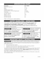 3
3
-
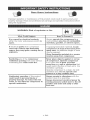 4
4
-
 5
5
-
 6
6
-
 7
7
-
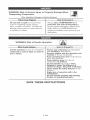 8
8
-
 9
9
-
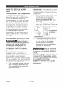 10
10
-
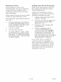 11
11
-
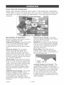 12
12
-
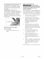 13
13
-
 14
14
-
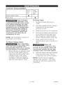 15
15
-
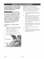 16
16
-
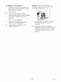 17
17
-
 18
18
-
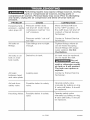 19
19
-
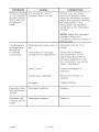 20
20
-
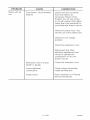 21
21
-
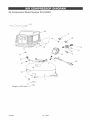 22
22
-
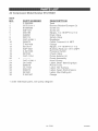 23
23
-
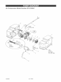 24
24
-
 25
25
-
 26
26
-
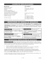 27
27
-
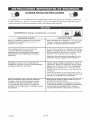 28
28
-
 29
29
-
 30
30
-
 31
31
-
 32
32
-
 33
33
-
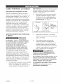 34
34
-
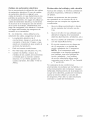 35
35
-
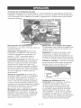 36
36
-
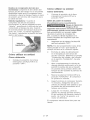 37
37
-
 38
38
-
 39
39
-
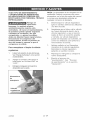 40
40
-
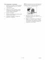 41
41
-
 42
42
-
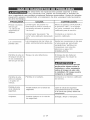 43
43
-
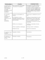 44
44
-
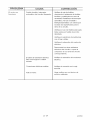 45
45
-
 46
46
-
 47
47
-
 48
48


Craftsman 919165381 El manual del propietario
- Categoría
- Compresores de aire
- Tipo
- El manual del propietario
en otros idiomas
- English: Craftsman 919165381 Owner's manual
Artículos relacionados
-
Craftsman 919168700 El manual del propietario
-
-
-
-
-
-
-
-
-
Craftsman 919.167782 El manual del propietario

