Southern States 96042001300 El manual del propietario
- Categoría
- Tractor
- Tipo
- El manual del propietario

OPERATOR'S MANUAL
MODEL NO. SOGT22H48
22.0 HP 48 INCH
TRACTOR
|
• Assembly
• Operation
• Maintenance
• Service and Adjustments
• Storage
• Troubleshooting
• Espahol
For Parts and Service, contact our authorized distributor:
call 1-800-849-1297 For Technical Assistance: call 1-800-829-5886
SOUTHERN STATES
402670 Rev.2 03.27.06 VB
PRINTED IN U.S.A.

Warranty ................................................ 2
Safety Rules .......................................... 3
Product Specifications ........................... 6
Assembly/Pre-Operation ....................... 7
Operation ............................................... 9
Maintenance Schedule ........................ 17
Maintenance ........................................ 17
Service and Adjustments ..................... 21
Storage ................................................ 29
Troubleshooting ................................... 30
Service .................................. Back Cover
LIMITED WARRANTY
The Manufacturer warrants to the original consumer purchaser that this product as
manufactured is free from defects in materials and workmanship. For a period of two
(2) years from date of purchase by the original consumer purchaser, we will repair or
replace, at our option, without charge for parts or labor incurred in replacing parts, any
part which we find to be defective due to materials or workmanship. This Warranty is
subject to the following limitations and exclusions.
1. This warranty does not apply to the engine, other than EHP manufactured transaxle/
transmission components, battery (except as noted below) or components parts
thereof. Please refer to the applicable manufacturer's warranty on these items.
2. Transportation charges for the movement of any power equipment unit or attachment
are the responsibility of the purchaser. Transportation charges for any parts submit-
ted for replacement under this warranty must be paid by the purchaser unless such
return is requested by Electrolux Home Products.
3. Battery Warranty: On products equipped with a Battery, we will replace, without
charge to you, any battery which we find to be defective in manufacture, during the
first ninety (90) days of ownership. After ninety (90) days, we will exchange the Bat-
tery, charging you 1/12 of the price of a new Battery for each full month from the date
of the original sale. Battery must be maintained in accordance with the instructions
furnished.
4. The Warranty period for any products used for rental or commercial purposes is
limited to 90 days from the date of original purchase.
5. This Warranty applies only to products which have been properly assembled, ad-
justed, operated, and maintained in accordance with the instructions furnished. This
Warranty does not apply to any product which has been subjected to alteration, mis-
use, abuse, improper assembly or installation, delivery damage, or to normal wear of
the product.
6. Exclusions: Excluded from this Warranty are belts, blades, blade adapters, normal
wear, normal adjustments, standard hardware and normal maintenance.
7. In the event you have a claim under this Warranty, you must return the product to an
authorized service dealer.
Should you have any unanswered questions concerning this Warranty, please contact:
Electrolux Home Products, Inc. In Canada contact:
Outdoor Products Customer Service Dept. Electrolux Canada Corp.
250 Bobby Jones Expressway 7075 Ordan Drive
Augusta, GA 30909 USA Mississauga, Ontario
L5T 1K6
giving the model number, serial number and date of purchase of your product and the
name and address of the authorized dealer from whom it was purchased.
THIS WARRANTY DOES NOT APPLY TO INCIDENTAL OR CONSEQUENTIAL
DAMAGES AND ANY IMPLIED WARRANTIES ARE LIMITED TO THE SAME TIME
PERIODS STATED HEREIN FOR OUR EXPRESSED WARRANTIES. Some areas do
not allow the limitation of consequential damages or limitations of how long an implied
Warranty may last, so the above limitations or exclusions may not apply to you. This
Warranty gives you specific legal rights, and you may have other rights which vary from
locale to locale.
This is a limited Warranty within the meaning of that term as defined in the Magnuson-
Moss Act of 1975.

_,DANGER: This cutting machine is capable of amputating hands and feet and
throwing objects. Failure to observe the following safety instructions could result
in serious injury or death.
_WARNING: In order to prevent ac-
cidental starting when setting up, trans-
porting, adjusting or making repairs,
always disconnect spark plug wire and
place wire where it cannot contact spark
plug.
_I_WARNING: Do not coast down a hill in
neutral, you may lose control of the tractor.
,_WARNING: Tow only the attachments
that are recommended by and comply with
specifications of the manufacturer of your
tractor. Use common sense when towing.
Operate only at the lowest possible speed
when on a slope. Too heavy of a load,
while on a slope, is dangerous. Tires can
lose traction with the ground and cause
you to lose control of your tractor.
_,WARNING: Engine exhaust, some of
its constituents, and certain vehicle com-
ponents contain or emit chemicals known
to the State of California to cause cancer
and birth defects or other reproductive
harm.
_,WARNING: Battery posts, terminals
and related accessories contain lead and
lead compounds, chemicals known to the
State of California to cause cancer and
birth defects or other reproductive harm.
Wash hands after handling.
I. GENERAL OPERATION
• Read, understand, and follow all
instructions on the machine and in the
manual before starting.
• Do not put hands or feet near rotating
parts or under the machine. Keep clear
of the discharge opening at all times.
• Only allow responsible adults, who are
familiar with the instructions, to operate
the machine.
• Clear the area of objects such as
rocks, toys, wire, etc., which could be
picked up and thrown by the blades.
• Be sure the area is clear of bystand-
ers before operating. Stop machine if
anyone enters the area.
• Never carry passengers.
• Do not mow in reverse unless abso-
lutely necessary. Always look down
and behind before and while backing.
• Never direct discharged material
toward anyone. Avoid discharging
material against a wall or obstruction.
Material may ricochet back toward the
operator. Stop the blades when cross-
ing gravel surfaces.
• Do not operate machine without the
entire grass catcher, discharge guard,
or other safety devices in place and
working.
• Slowdown before turning.
• Never leave a running machine
unattended. Always turn off blades,
set parking brake, stop engine, and
remove keys before dismounting.
• Disengage blades when not mowing.
Shut off engine and wait for all parts to
come to a complete stop before clean-
ing the machine, removing the grass
catcher, or unclogging the discharge
guard.
• Operate machine only in daylight or
good artificial light.
• Do not operate the machine while
under the influence of alcohol or drugs.
• Watch for traffic when operating near
or crossing roadways.
• Use extra care when loading or unload-
ing the machine into a trailer or truck.
• Always wear eye protection when oper-
ating machine.
• Data indicates that operators, age 60
years and above, are involved in a
large percentage of riding mower-re-
lated injuries. These operators should
evaluate their ability to operate the
riding mower safely enough to protect
themselves and others from serious
injury.
• Follow the manufacturer's recommen-
dation for wheel weights or counter-
weights.
• Keep machine free of grass, leaves
or other debris build-up which can
touch hot exhaust / engine parts and
burn. Do not allow the mower to plow
leaves or other debris which can cause
build-up to occur. Clean any oil or fuel
spillage before operating or storing the
machine. Allow machine to cool before
storage.
3

II. SLOPE OPERATION
Slopes are a major factor related to loss of
control and tip-over accidents, which can
result in severe injury or death. Opera-
tion on all slopes requires extra caution. If
you cannot back up the slope or if you feel
uneasy on it, do not mow it.
• Mow up and down slopes, not across.
• Watch for holes, ruts, bumps, rocks, or
other hidden objects. Uneven terrain
could overturn the machine. Tall grass
can hide obstacles.
• Choose a low ground speed so that
you will not have to stop or shift while
on the slope.
• Do not mow on wet grass. Tires may
lose traction.
Always keep the machine in gear when
going down slopes. Do not shift to
neutral and coast downhill.
• Avoid starting, stopping, or turning on
a slope. If the tires lose traction, dis-
engage the blades and proceed slowly
straight down the slope.
• Keep all movement on the slopes slow
and gradual. Do not make sudden
changes in speed or direction, which
could cause the machine to roll over.
• Use extra care while operating ma-
chine with grass catchers or other at-
tachments; they can affect the stability
of the machine. Do no use on steep
slopes.
• Do not try to stabilize the machine by
putting your foot on the ground.
• Do not mow near drop-offs, ditches,
or embankments. The machine could
suddenly roll over if a wheel is over the
edge or if the edge caves in.
II1. CHILDREN
Tragic accidents can occur if the operator
is not alert to the presence of children.
Children are often attracted to the machine
and the mowing activity. Never assume
that children will remain where you last
saw them.
• Keep children out of the mowing area
and in the watchful care of a respon-
sible adult other than the operator.
• Be alert and turn machine off if a child
enters the area.
• Before and while backing, look behind
and down for small children.
• Never carry children, even with the
blades shut off. They may fall off and
be seriously injured or interfere with
safe machine operation. Children who
have been given rides in the past may
suddenly appear in the mowing area
for another ride and be run over or
backed over by the machine.
• Never allow children to operate the
machine.
• Use extra care when approaching blind
corners, shrubs, trees, or other objects
that may block your view of a child.
IV, TOWING
• Tow only with a machine that has a
hitch designed for towing. Do not at-
tach towed equipment except at the
hitch point.
• Followthe manufacturer's recom-
mendation for weight limits for towed
equipment and towing on slopes.
• Never allow children or others in or on
towed equipment.
• On slopes, the weight of the towed
equipment may cause loss of traction
and loss of control.
• Travel slowly and allow extra distance
to stop.
V. SERVICE
SAFE HANDLING OF GASOLINE
To avoid personal injury or property
damage, use extreme care in handling
gasoline. Gasoline is extremely flammable
and the vapors are explosive.
• Extinguish all cigarettes, cigars, pipes,
and other sources of ignition.
• Use only approved gasoline container.
• Never remove gas cap or add fuel with
the engine running. Allow engine to
cool before refueling.
• Never fuel the machine indoors.
• Never store the machine or fuel con-
tainer where there is an open flame,
spark, or pilot light such as on a water
heater or other appliances.
• Never fill containers inside a vehicle
or on a truck or trailer bed with plastic
liner. Always place containers on the
ground away from your vehicle when
filling.

• Remove gas-powered equipment from
the truck or trailer and refuel it on the
ground. If this is not possible, then
refuel such equipment with a portable
container, rather than from a gasoline
dispenser nozzle.
• Keep the nozzle in contact with the rim
of the fuel tank or container opening at
all times until fueling is complete. Do
not use a nozzle lock-open device.
• If fuel is spilled on clothing, change
clothing immediately.
• Never overfill fuel tank. Replace gas
cap and tighten securely.
GENERAL SERVICE
• Never operate machine in a closed
area.
• Keep all nuts and bolts tight to be sure
the equipment is in safe working condi-
tion.
• Never tamper with safety devices.
Check their proper operation regularly.
• Keep machine free of grass, leaves, or
other debris build-up. Clean oil or fuel
spillage and remove any fuel-soaked
debris. Allow machine to cool before
storing.
• If you strike a foreign object, stop and
inspect the machine. Repair, if neces-
sary, before restarting.
• Never make any adjustments or repairs
with the engine running.
• Check grass catcher components and
the discharge guard frequently and
replace with manufacturer's recom-
mended parts, when necessary.
• Mower blades are sharp. Wrap the
blade or wear gloves, and use extra
caution when servicing them.
• Check brake operation frequently. Ad-
just and service as required.
• Maintain or replace safety and instruc-
tion labels, as necessary.
• Be sure the area is clear of bystand-
ers before operating. Stop machine if
anyone enters the area.
• Never carry passengers.
• Do not mow in reverse unless abso-
lutely necessary. Always look down
and behind before and while backing.
• Never carry children, even with the
blades shut off. They may fall off and
be seriously injured or interfere with
safe machine operation. Children who
have been given rides in the past may
suddenly appear in the mowing area
for another ride and be run over or
backed over by the machine.
• Keep children out of the mowing area
and in the watchful care of a respon-
sible adult other than the operator.
• Be alert and turn machine off if a child
enters the area.
• Before and while backing, look behind
and down for small children.
• Mow up and down slopes (15 ° Max),
not across.
• Choose a low ground speed so that
you will not have to stop or shift while
on the slope.
• Avoid starting, stopping, or turning on
a slope. If the tires lose traction, dis-
engage the blades and proceed slowly
straight down the slope.
• If machine stops while going uphill,
disengage blades, shift into reverse
and back down slowly.
• Do not turn on slopes unless neces-
sary, and then, turn slowly and gradu-
ally downhill, if possible.
5

PRODUCT SPECIFICATIONS
Gasoline Capacity 4 Gallons
and Type: Unleaded Regular
Oil Type SAE 30 (above 32°F)
API-SG-SL): SAE 5W30 (below 32°F
Oil Capacity: W/Filter: 4.0 Pints
W/O Filter: 3.75 Pints
Spark Plug: Champion QC12YC
(Gap: .040")
Ground Speed Forward: 0-5.8
Reverse: 0-2.1
Charging System: 16 Amps @ 3600 RPM
Battery: Amp/Hr: 35
Min. CCA: 280
Case size: U1R
Blade Bolt Torque: 45-55 Ft. Lbs.
CONGRATULATIONS on your purchase
of a new tractor. It has been designed,
engineered and manufactured to give
you the best possible dependability and
performance.
Should you experience any problem you
cannot easily remedy, please contact a
qualified service center. We have com-
petent, well-trained technicians and the
proper tools to service or repair this trac-
tor.
Please read and retain this manual. The
instructions will enable you to assemble
and maintain your tractor properly. Always
observe the "SAFETY RULES".
CUSTOMER RESPONSIBILITIES
• Read and observe the safety rules.
• Follow a regular schedule in main-
taining, caring for and using your tractor.
• Follow the instructions under "Mainte-
nance" and "Storage" sections of this
owner's manual.
_IbWARNING: This tractor is equipped
with an internal combustion engine and
should not be used on or near any unim-
proved forest-covered, brush-covered or
grass-covered land unless the engine's
exhaust system is equipped with a spark
arrester meeting applicable local or state
laws (if any). If a spark arrester is used, it
should be maintained in effective working
order by the operator.
In the state of California the above is
required by law (Section 4442 of the
California Public Resources Code). Other
states may have similar laws. Federal
laws apply on federal lands. A spark ar-
rester for the muffler is available through
your nearest service center (See REPAIR
PARTS manual).

Keys
(1) Oil Drain Tube
For Future Use
Slope Sheet
(2) Keys
Your new tractor has been assembled at the factory with the exception of those parts left
unassembled for shipping purposes.
When right or left hand is mentioned in
this manual, it means, from your point of
view, when you are in the operating posi-
tion (seated behind the steering wheel).
TO REMOVE TRACTOR FROM
CARTON
UNPACK CARTON
1. Cut along dashed lines on all four pan-
els of carton. Remove end panels and
lay side panels flat.
2. Remove protective materials from trac-
tor hood and grille.
IMPORTANT: Check for and remove any
staples in skid that may puncture tires
where tractor is to roll off skid.
CHECK BATTERY
1. Lift hood to raised position.
NOTE: If this battery is put into service
after month and year indicated on label
(L) (label is located between terminals)
charge battery for minimum of one hour at
6-10 amps. (See "BATTERY" in Mainte-
nance section of this manual for charging
instructions).
ADJUST SEAT
1. Sit in seat.
2. Lift up adjustment lever (A) and slide
seat until a comfortable position is
reached which allows you to press
clutch/brake pedal all the way down.
3. Release lever to lock seat in position.
7
NOTE: You may now roll or drive your
tractor off the skid. Follow the appropriate
instruction below to remove the tractor
from the skid.
_i, WARNING: Before starting, read, un-
derstand and follow all instructions in the
Operation section of this manual. Be sure
tractor is in a well-ventilated area. Be sure
the area in front of tractor is clear of other
people and objects.
TO ROLL TRACTOR OFF SKID (See
Operation section for location and
function of controls)
1. Raise attachment lift lever to its highest
position.
2. Release parking brake by depressing
brake pedal.
3. Place freewheel control in disengaged
position to disengage transmission
(See "TO TRANSPORT" in the Op-
eration section of this manual).
4. Roll tractor forward off skid.

5.Removebandingholdingthedeflector
shield upagainsttractor.
TO DRIVE TRACTOR OFF SKID (See
Operation section for location and
function of controls)
1. Be sure all the above assembly steps
have been completed.
2. Check engine oil level and fill fuel tank
with gasoline.
3. Place freewheel control in "trans-
mission engaged" position (see "TO
TRANSPORT" in Operation section of
this manual).
4. Sit on seat in operating position, de-
press brake pedal and set the parking
brake.
5. Raise attachment lift lever to its highest
position.
6. Remove key from bag and start the
engine (see "TO START ENGINE" in
the Operation section of this manual).
After engine has started, move throttle
control to idle (slow) position.
7. Release parking brake.
8. Slowly depress forward drive pedal and
drive tractor off skid.
9. Apply brake to stop tractor and set
parking brake.
10. Turn ignition key to "STOP" position.
Continue with the instructions that follow.
CHECK TIRE PRESSURE
The tires on your tractor were overinflated
at the factory for shipping purposes. Cor-
rect tire pressure is important for best
cutting performance.
• Reduce tire pressure to PSI shown on
tires.
CHECK DECK LEVELNESS
For best cutting results, mower hous-
ing should be properly leveled. See "TO
LEVEL MOWER" in the Service and
Adjustments section of this manual.
CHECK FOR PROPER POSITION
OF ALL BELTS
See the figures that are shown for replac-
ing motion and mower blade drive belts
in the Service and Adjustments section
of this manual. Verify that the belts are
routed correctly.
CHECK BRAKE SYSTEM
After you learn how to operate your trac-
tor, check to see that the brake is operat-
ing properly. See "TO CHECK BRAKE"
in the Service and Adjustments section of
this manual.
,/CHECKLIST
Before you operate your new tractor, we
wish to assure that you receive the best
performance and satisfaction from this
Quality Product.
Please review the following checklist:
¢" All assembly instructions have been
completed.
¢" No remaining loose parts in carton.
¢" Battery is properly prepared and
charged.
¢" Seat is adjusted comfortably and tight-
ened securely.
¢" All tires are properly inflated. (For ship-
ping purposes, the tires were overin-
flated at the factory).
¢" Be sure mower deck is properly leveled
side-to-side/front-to-rear for best cutting
results. (Tires must be properly inflated
for leveling).
¢" Check mower and drive belts. Be sure
they are routed properly around pulleys
and inside all belt keepers.
¢" Check wiring. See that all connections
are still secure and wires are properly
clamped.
¢" Before driving tractor, be sure freewheel
control is in "transmission engaged"
position (see "TO TRANSPORT" in the
Operation section of this manual).
While learning how to use your tractor, pay
extra attention to the following important
items:
¢" Engine oil is at proper level.
¢" Fuel tank is filled with fresh, clean, regu-
lar unleaded gasoline.
¢" Become familiar with all controls, their
location and function. Operate them
before you start the engine.
¢" Be sure brake system is in safe operat-
ing condition.
¢" Be sure Operator Presence System
and Reverse Operation System (ROS)
are working properly (See the Opera-
tion and Maintenance sections in this
manual).
¢" It is important to purge the transmission
before operating your tractor for the first
time. Follow proper starting and transmis-
sion purging instructions (See "TO START
ENGINE" and "PURGE TRANSMISSION"
in the Operation section of this manual).

Thesesymbolsmayappearon yourtractororin literaturesuppliedwiththe product,
Learnandunderstandtheir meaning.
R N H I ,1
REVERSE NEUTRAL HIGH LOW CHOKE FAST SLOW
ENGINE OFF REVERSE ENGINE ON ENGINE START PARKING BRAKE MOWER HEIGHT
OPERATION
SYSTEM (ROS)
REVERSELIGHTS ON FUEL BATTERY
ATTACHMENT ATTACHMENT
CLUTCH DISENGAGED CLUTCH ENGAGED
FREE WHEEL
(Automatic Models only)
IGNITION SWITCH
MOWER LIFT
t
FORWARD
DANGER, KEEP HANDS
AND FEET AWAY
CRUISE CONTROL CLUTCH/BRAKE
PEDAL
KEEP AREA CLEAR SLOPE HAZARDS
(SEE SAFETY RULES SECTION)
&
Failure to follow instructions
could result in serious injury or
death. The safety alert symbol
is used to identify safety inform-
ation about hazards which can
result in death, serious injury
and/or property damage.
&
&
&
,_l_llIII/£1il,,
DANGER indicates a hazard which, if not avoided,
will result in death or serious injury.
WARNING indicates a hazard which, if not avoided
could result in death or serious injury.
CAUTION indicates a hazard which, if not avoided
might result in minor or moderate injury.
CAUTION when used without the alert symbol,
indicates a situation that could result in damage
to the tractor and/or engine.
HOT SURFACES indicates a hazard which,
if not avoided, could result in death, serious injury
and/or property damage.
FIRE indicates a hazard which, if not avoided,
could result in death, serious injury and/or
property damage.
9

KNOW YOUR TRACTOR
READ THIS OWNER'S MANUAL AND SAFETY RULES BEFORE OPERATING YOUR
TRACTOR
Compare the illustrations with your tractor to familiarize yourself with the locations of
various controls and adjustments. Save this manual for future reference.
03105
Our tractors conform to the applicable safety standards of the
American National Standards Institute.
(A) ATTACHMENT LIFT LEVER - Used
to raise and lower the mower or other at-
tachments mounted to your tractor.
(B) BRAKE PEDAL - Used for braking
the tractor and starting the engine.
(C) PARKING BRAKE - Locks clutch/
brake pedal into the brake position.
(D) THROTTLE CONTROL - Used to
control engine speed.
(E) ATTACHMENT CLUTCH SWITCH
- Used to engage the mower blades, or
other attachments mounted to your tractor.
(F) IGNITION SWITCH - Used for starting
and stopping the engine.
(G) REVERSE OPERATION SYSTEM
(ROS) "ON" POSITION - Allows opera-
tion of mower or other powered attach-
ment while in reverse.
(H) LIGHT SWITCH - Turns the head-
lights on and off.
(J) CRUISE CONTROL LEVER- Used to
set forward movement of tractor at desired
speed without holding the forward drive
pedal.
(K) FORWARD DRIVE PEDAL - Used for
forward movement of tractor.
(L) REVERSE DRIVE PEDAL - Used for
reverse movement of tractor.
(M) FREEWHEEL CONTROL - Disen-
gages transmission for pushing or slowly
towing the tractor with the engine off.
(N) CHOKE CONTROL - Used when
starting a cold engine.
(P) SERVICE REMINDER / HOUR METER
- Indicates when service is required for
the engine and mower.
(Q) 12-VOLT POWER PORT- Used for
12-volt accessories.
10

The operation of any tractor can result in foreign objects thrown into the
eyes, which can result in severe eye damage. Always wear safety glasses
or eye shields while operating your tractor or performing any adjustments
or repairs. We recommend standard safety glasses or a wide vision safety
mask worn over spectacles.
HOW TO USE YOUR TRACTOR
TO SET PARKING BRAKE
Your tractor is equipped with an operator
presence sensing switch. When engine
is running, any attempt by the operator
to leave the seat without first setting the
parking brake will shut off the engine.
1. Depress brake pedal (B) all the way
down and hold.
2. Pull parking brake lever (C) up and
hold, release pressure from brake
pedal (B), then release parking brake
lever. Pedal should remain in brake
position. Make sure parking brake will
hold tractor secure.
STOPPING
GROUND DRIVE -
• To stop ground drive, depress brake
pedal all the way down.
ENGINE -
• Move throttle control (D) between half
and full speed (fast) position.
NOTE: Failure to move throttle control
between half and full speed (fast) posi-
tion, before stopping, may cause engine to
"backfire".
• Turn ignition key (F) to "STOP" position
and remove key. Always remove key
when leaving tractor to prevent unau-
thorized use.
• Never use choke (N) to stop engine.
IMPORTANT: Leaving the ignition switch
in any position other than "STOP" will
cause the battery to discharge and go
dead.
NOTE: Under certain conditions when
tractor is standing idle with the engine
running, hot engine exhaust gases may
cause "browning" of grass. To eliminate
this possibility, always stop engine when
stopping tractor on grass areas.
_ICAUTION: Always stop tractor com-
pletely, as described above, before leaving
the operator's position.
MOWER BLADES -
• To stop mower blades, push attachment
clutch switch in to disengaged position
(1_1) Attachment
Clutch
Engage Position
(_) Disengaged
Position
TO USE THROTTLE CONTROL (D)
Always operate engine at full speed (fast).
• Operating engine at less than full speed
(fast) reduces engine's operating ef-
ficiency.
• Full speed (fast) offers the best mower
performance.
11

TO USE CHOKE CONTROL (N)
Use choke control whenever you are
starting a cold engine. Do not use to start
a warm engine.
• To engage choke control, pull knob out.
Slowly push knob in to disengage.
TO MOVE FORWARD AND
BACKWARD
The direction and speed of movement
is controlled by the forward and reverse
drive pedals.
1. Start tractor and release parking brake.
2. Slowly depress forward (K) or reverse
(L) drive pedal to begin movement.
Ground speed increases the further
down the pedal is depressed.
TO USE CRUISE CONTROL
The cruise control feature can be used for
forward travel only.
SYSTEM CHARACTERISTICS
The cruise control should only be used
while mowing or transporting on relatively
smooth, straight surfaces. Other conditions
such as trimming at slow speeds may
cause the cruise control to disengage. Do
not use the cruise control on slopes, rough
terrian or while trimmimg or turning.
• With forward drive pedal (K) depressed
to desired speed, pull cruise control
lever (J) up and hold while lifting your
foot off the pedal, then release the lever.
To disengage the cruise control, depress
the brake pedal or tap on forward drive
pedal.
TO ADJUST MOWER CUTTING HEIGHT
The position of the attachment lift lever (A)
determines the cutting height.
• Put attachment lift lever in desired cut-
ting height slot.
• Slide pointer tab (T) to desired cutting
height as a reminder for next time you
mow.
The cutting height range is approxi-
mately 1" to 4". The heights are mea-
sured from the ground to the blade tip with
the engine not running. These heights
are approximate and may vary depending
upon soil conditions, height of grass and
types of grass being mowed.
• The average lawn should be cut to ap-
proximately 2-1/2 inches during the cool
season and to over 3 inches during hot
months. For healthier and better looking
lawns, mow often and after moderate
growth.
• For best cutting performance, grass over
6 inches in height should be mowed
twice. Make the first cut relatively high;
the second to desired height.
TO ADJUST GAUGE WHEELS
Gauge wheels are properly adjusted
when they are slightly off the ground when
mower is at the desired cutting height in
operating position. Gauge wheels then
keep the deck in proper position to help
prevent scalping in most terrain conditions.
NOTE: Adjust gauge wheels with tractor
on a flat level surface.
1. Adjust mower to desired cutting height
(See "TO ADJUST MOWER CUTTING
HEIGHT" in this section of manual).
2. With mower in desired height of cut
position, gauge wheels should be
assembled so they are slightly off the
ground. Install gauge wheel in appro-
priate hole. Tighten securely.
3. Repeat for all, installing gauge wheel in
same adjustment hole.
12

TO OPERATE MOWER
Your tractor is equipped with an operator
presence sensing switch. Any attempt
by the operator to leave the seat with the
engine running and the attachment clutch
engaged will shut off the engine. You must
remain fully and centrally positioned in the
seat to prevent the engine from hesitating
or cutting off when operating your equip-
ment on rough, rolling terrain or hills.
1. Select desired height of cut with at-
tachment lift lever.
2. Start mower blades by engaging at-
tachment clutch control.
TO STOP MOWER BLADES -
disengage attachment clutch control.
,_CAUTION: Do not operate the mower
without either the entire grass catcher,
on mowers so equipped, or the deflector
shield (S)in place.
REVERSE OPERATION SYSTEM (ROS)
Your tractor is equipped with a Reverse
Operation System (ROS). Any attempt by
the operator to travel in the reverse direc-
tion with the attachment clutch engaged
will shut off the engine unless ignition key
is placed in the ROS "ON" position.
,_WARNING: Backing up with the at-
tachment clutch engaged while mowing
is strongly discouraged. Turning the ROS
"ON", to allow reverse operation with the
attachment clutch engaged, should only
be done when the operator decides it is
necessary to reposition the machine with
the attachment engaged. Do not mow in
reverse unless absolutely necessary.
USING THE REVERSE OPERATION
SYSTEM -
Only use if you are certain no children or
other bystanders will enter the mowing
area.
1. Depress brake pedal all the way down.
2. With engine running, turn ignition key
counterclockwise to ROS "ON" posi-
tion.
3. Look down and behind before and
while backing.
4. Slowly depress reverse drive pedal to
start movement.
5. When use of the ROS is no longer
needed, turn the ignition key clockwise
to engine "ON" position.
ROS "ON" Position Engine "ON" Position
(Normal Operating)
TO OPERATE ON HILLS
,4_WARNING: Do not drive up or down
hills with slopes greater than 15 ° and do
not drive across any slope. Use the slope
guide provided at the back of this manual.
• Choose the slowest speed before start-
ing up or down hills.
• Avoid stopping or changing speed on
hills.
• If stopping is absolutely necessary, push
brake pedal quickly to brake position
and engage parking brake.
• To restart movement, slowly release
parking brake and brake pedal.
• Slowly depress appropriate drive pedal
to slowest setting.
• Make all turns slowly.
13

TO TRANSPORT
When pushing or towing your tractor, be
sure to disengage transmission by placing
freewheel control in freewheeling position.
Freewheel control is located at the rear
drawbar of tractor.
1. Raise attachment lift lever to its highest
position.
2. Pull freewheel control out and into the
slot and release so it is held in the
disengaged position.
• Do not push or tow tractor at more than
two (2) MPH.
• To re-engage transmission, reverse
above procedure.
Transmission Engaged
Transmission Disengaged
NOTE: To protect hood from damage when
transporting your tractor on a truck or a
trailer, be sure hood is closed and secured
to tractor. Use an appropriate means of
tying hood to tractor (rope, cord, etc.).
TOWING CARTS AND OTHER ATTACH-
MENTS
Tow only the attachments that are recom-
mended by and comply with specifications
of the manufacturer of your tractor. Use
common sense when towing. Too heavy
of a load, while on a slope, is dangerous.
Tires can lose traction with the ground and
cause you to lose control of your tractor.
SERVICE REMINDER/HOUR METER
Service reminder shows the total number
of hours the engine has run and flashes to
indicate that the engine or mower needs
servicing. When service is required, the
service reminder will flash for two hours.
To service engine and mower, see the
Maintenance section of this manual.
NOTE: Service reminder runs when the
ignition key is in any position but "STOP".
For accurate reading, be sure key remains
in the "STOP" position when engine is not
running.
BEFORE STARTING THE ENGINE
CHECK ENGINE OIL LEVEL
The engine in your tractor has been
shipped, from the factory, already filled
with summer weight oil.
1. Check engine oil with tractor on level
ground.
2. Remove oil fill cap/dipstick and wipe
clean, reinsert the dipstick and screw
cap tight, wait for a few seconds, re-
move and read oil level. If necessary,
add oil until "FULL" mark on dipstick is
reached. Do not overfill.
• For cold weather operation you should
change oil for easier starting (See the
oil viscosity chart in the Maintenance
section of this manual).
• To change engine oil, see the Mainte-
nance section in this manual.
ADD GASOLINE
• Fill fuel tank to bottom of filler neck. Do
not overfill. Use fresh, clean, regular
unleaded gasoline with a minimum of
87 octane. (Use of leaded gasoline will
increase carbon and lead oxide deposits
and reduce valve life). Do not mix oil
with gasoline. Purchase fuel in quan-
tities that can be used within 30 days to
assure fuel freshness.
ACAUTION: Wipe off any spilled oil or
fuel. Do not store, spill or use gasoline
near an open flame.
IMPORTANT: When operating in temper-
atures below32°F(0°C), use fresh, clean
winter grade gasoline to help insure good
cold weather starting.
CAUTION: Alcohol blended fuels (called
gasohol or using ethanol or methanol) can
attract moisture which leads to separa-
tion and formation of acids during storage.
Acidic gas can damage the fuel system
of an engine while in storage. To avoid
engine problems, the fuel system should
be emptied before storage of 30 days
or longer. Drain the gas tank, start the
engine and let it run until the fuel lines
and carburetor are empty. Use fresh fuel
next season. See Storage Instructions for
additional information. Never use engine
or carburetor cleaner products in the fuel
tank or permanent damage may occur.
14

TO START ENGINE
When starting the engine for the first time
or if the engine has run out of fuel, it will
take extra cranking time to move fuel from
the tank to the engine.
1. Be sure freewheel control is in the
transmission engaged position.
2. Sit on seat in operating position,
depress brake pedal and set parking
brake.
3. Move attachment clutch to disengaged
position.
4. Move throttle control to fast position
5. Pull choke control out for a cold engine
start attempt. For a warm engine start
attempt the choke control may not be
needed.
NOTE: Before starting, read the warm and
cold starting procedures below.
6. Insert key into ignition and turn key
clockwise to start position and release
key as soon as engine starts. Do
not run starter continuously for more
than fifteen seconds per minute. If the
engine does not start after several
attempts, push choke control in, wait
a few minutes and try again. If engine
still does not start, pull the choke con-
trol out and retry.
WARM WEATHER STARTING (50 ° F and
above)
7. When engine starts, slowly push choke
control in until the engine begins to
run smoothly. If the engine starts to
run roughly, pull the choke control out
slightly for a few seconds and then
continue to push the control in slowly.
• The attachments and ground drive can
now be used. If the engine does not
accept the load, restart the engine and
allow it to warm up for one minute using
the choke as described above.
COLD WEATHER STARTING (50 ° F and
below)
7. When engine starts, slowly push choke
control in until the engine begins to run
smoothly. Continue to push the choke
control in small steps allowing the en-
gine to accept small changes in speed
and load, until the choke control is fully
in. If the engine starts to run roughly,
pull the choke control out slightly for a
few seconds and then continue to push
the control in slowly. This may require
an engine warm-up period from several
seconds to several minutes, depending
on the temperature.
AUTOMATIC TRANSMISSION WARM UP
Before driving the unit in cold weather,
the transmission should be warmed up as
follows:
1. Be sure the tractor is on level ground.
2. Release the parking brake and let the
brake slowly return to operating posi-
tion.
3. Allow one minute for transmission to
warm up. This can be done during the
engine warm up period.
• The attachments can be used during
the engine warm-up period after the
transmission has been warmed up and
may require the choke control be pulled
out slightly.
NOTE: If at a high altitude (above 3000
feet) or in cold temperatures (below 32 F)
the carburetor fuel mixture may need to
be adjusted for best engine performance
(see "TO ADJUST CARBURETOR" in the
Service and Adjustments section of this
manual).
RGE TRANSMISSION
CAUTION: Never engage or dis-
engage freewheel lever while the engine
is running.
To ensure proper operation and per-
formance, it is recommended that the
transmission be purged before operating
tractor for the first time. This procedure will
remove any trapped air inside the trans-
mission which may have developed during
shipping of your tractor.
IMPORTANT: Should your transmission
require removal for service or replace-
ment, it should be purged after reinstall-
ation before operating the tractor.
1. Place tractor safely on a level surface
- that is clear of objects and open - with
engine off and parking brake set.
2. Disengage transmission by placing
freewheel control in disengaged posi-
tion (See "TO TRANSPORT" in this
section of manual).
3. Sitting in the tractor seat, start engine.
After the engine is running, move
throttle control to slow position. Disen-
,_gage parking brake.
AUTION: At any time, during step
4, there may be movement of the drive
wheels.
15

4. Depress forward drive pedal to full
forward position and hold for five (5)
seconds and release pedal. Depress
reverse drive pedal to full reverse posi-
tion and hold for five (5) seconds and
release pedal. Repeat this procedure
three (3) times.
5. Shutoff engine and set parking brake.
6. Engage transmission by placing free-
wheel control in engaged position (See
"TO TRANSPORT" in this section of
manual).
7. Sitting in the tractor seat, start engine.
After the engine is running, move
throttle control to half (1/2) speed.
Disengage parking brake.
8. Drive tractor forward for approximately
five feet then backwards for five feet.
Repeat this driving procedure three
times.
Your transmission is now purged and now
ready for normal operation.
MOWING TIPS
• Tire chains cannot be used when the
mower housing is attached to tractor.
• Mower should be properly leveled for
best mowing performance. See "TO
LEVEL MOWER HOUSING" in the
Service and Adjustments section of this
manual.
• The left hand side of mower should be
used for trimming.
• Drive so that clippings are discharged
onto the area that has already been
cut. Have the cut area to the right of
the tractor. This will result in a more
even distribution of clippings and more
uniform cutting.
• When mowing large areas, start by
turning to the right so that clippings will
discharge away from shrubs, fences,
driveways, etc. After one or two rounds,
mow in the opposite direction making
left hand turns until finished.
......................................
• If grass is extremely tall, it should be
mowed twice to reduce load and pos-
sible fire hazard from dried clippings.
Make first cut relatively high; the second
to the desired height.
• Do not mow grass when it is wet.
Wet grass will plug mower and leave
undesirable clumps. Allow grass to dry
before mowing.
• Always operate engine at full throttle
when mowing to assure better mowing
performance and proper discharge of
material. Regulate ground speed by
selecting a low enough speed to give
the mower cutting performance as well
as the quality of cut desired.
• When operating attachments, select a
ground speed that will suit the terrain
and give best performance of the at-
tachment being used.
16

BEFORE EVERY EVERY EVERY EVERY EVERY BEFORE
EACH 8 25 50 100 SEASON STORAGE
USE HOURS HOURS HOURS HOURS
MAINTENANCE
SCHEDULE
Check Brake Operation
Check Tire Pressure
T
ii_ Check Operator Presence & ROS Systems
A Check for Loose Fasteners
C Check/Replace Mower Blades
T Lubrication Chart
0 Check Battery Level
R
Clean Battery and Terminals
Check Transaxle Cooling
Check Mower Levelness
Check V-Belts
Check Enqine Oil Level I_
Change Engine Oil (with oil filter)
Change Engine Oil (without oil filter
_ Clean Air Filter
G Clean Air Screen
Inspect Muffler/Spark Arrester
N Replace Oil Filter !If equipped)
E Clean Engine Cooling Fins
Replace Spark Plug
Replace Air Filter Paper Cartridge
__ Re lace Fuel Filter
i/
I," I/
i/ t/
III_1.2
i/
i/
i/
1 - Change more often when operating under a heavy load or 3 - Reptace blades more often when mowing in sandy soil.
in high ambient temperatures. 4 - Not required if equipped with maintenance-free battery.
2 - Service more often when operating in dirty or dusty conditions.
GENERAL RECOMMENDATIONS
The warranty on this tractor does not
cover items that have been subjected to
operator abuse or negligence. To receive
full value from the warranty, operator
must maintain tractor as instructed in this
manual.
Some adjustments will need to be made
periodically to properly maintain your
tractor.
At least once a season, check to see if
you should make any of the adjustments
described in the Service and Adjustments
section of this manual.
• At least once a year you should replace
the spark plug, clean or replace air filter,
and check blades and belts for wear.
A new spark plug and clean air filter
assure proper air-fuel mixture and help
your engine run better and last longer.
BEFORE EACH USE
1. Check engine oil level.
2. Check brake operation.
3. Check tire pressure.
4. Check operator presence and
ROS systems for proper operation.
5. Check for loose fasteners.
LUBRICATION CHART
Spindle ii I
Zerk _
@ Front Wheel
Bearing zerk( !
@ Steering
Sector Gear
Teeth I
Spindle
Zerk
Front Wheel
Bearing zerk
Engine
Mandrel
Zerks
dPGeneral Purpose Grease
@Refer to Maintenance "ENGINE" Section
IMPORTANT: Do not oil or grease the
pivot points which have special nylon
bearings. Viscous lubricants will attract
dust and dirt that will shorten the life of the
self-lubricating bearings. If you feel they
must be lubricated, use only a dry, pow-
dered graphite type lubricant sparingly.
17

TRACTOR
Always observe safety rules when per-
forming any maintenance.
BRAKE OPERATION
If tractor requires more than five (5) feet to
stop at highest speed in highest gear on a
level, dry concrete or paved surface, then
brake must be serviced. (See "TO CHECK
BRAKE" in the Service and Adjustments
section of this manual).
TIRES
• Maintain proper air pressure in all tires
(See PSI on tires).
• Keep tires free of gasoline, oil, or insect
control chemicals which can harm rubber.
• Avoid stumps, stones, deep ruts, sharp
objects and other hazards that may
cause tire damage.
NOTE: To seal tire punctures and prevent
flat tires due to slow leaks, tire sealant
may be purchased from your local parts
dealer. Tire sealant also prevents tire dry
rot and corrosion.
OPERATOR PRESENCE SYSTEM AND
REVERSE OPERATION SYSTEM (ROS)
Be sure operator presence and reverse
operation systems are working properly. If
your tractor does not function as de-
scribed, repair the problem immediately.
• The engine should not start unless the
brake pedal is fully depressed, and the
attachment clutch control is in the disen-
gaged position.
CHECK OPERATOR PRESENCE
SYSTEM
• When the engine is running, any at-
tempt by the operator to leave the seat
without first setting the parking brake
should shut off the engine.
• When the engine is running and the
attachment clutch is engaged, any at-
tempt by the operator to leave the seat
should shut off the engine.
• The attachment clutch should never op-
erate unless the operator is in the seat.
ROS "ON" Position Engine "ON" Position
(Normal Operating)
CHECK REVERSE OPERATION (ROS)
SYSTEM
• When the engine is running with the
ignition switch in the engine "ON" posi-
tion and the attachment clutch engaged,
any attempt by the operator to drive in
reverse should shut off the engine.
• When the engine is running with the
ignition switch in the ROS "ON" position
and the attachment clutch engaged,
any attempt by the operator to drive in
reverse should NOT shut off the engine.
BLADE CARE
For best results mower blades must be
sharp. Replace worn, bent or damaged
blades.
A CAUTION: Use only a replacement
blade approved by the manufacturer of
your tractor. Using a blade not approved
by the manufacturer of your tractor is
hazardous, could damage your tractor and
void your warranty.
BLADE REMOVAL
1. Raise mower to highest position to al-
low access to blades.
NOTE: Protect your hands with gloves
and/or wrap blade with heavy cloth.
2. Remove blade bolt by turning counter-
clockwise.
3. Install new blade with stamped
"GRASS SIDE" facing the ground.
IMPORTANT: To ensure proper assembly,
center hole in blade must align with star
on mandrel assembly.
4. Install and tighten blade bolt securely
(45-55 Ft. Lbs. torque).
IMPORTANT: Special blade bolt is heat
treated.
Blade
Blade Bolt Assembly
(Special)
Center Hole
BATTERY
Your tractor has a battery charging system
which is sufficient for normal use. How-
ever, periodic charging of the battery with
an automotive charger will extend its life.
• Keep battery and terminals clean.
• Keep battery bolts tight.
• Keep small vent holes open.
• Recharge at 6-10 amperes for 1 hour.
NOTE: The original equipment battery on
your tractor is maintenance free. Do not
attempt to open or remove caps or covers.
Adding or checking level of electrolyte is
not necessary.
18

TO CLEAN BATTERY AND TERMINALS
Corrosion and dirt on the battery and termi-
nals can cause the battery to "leak" power.
1. Disconnect BLACK battery cable first
then RED battery cable and remove
battery from tractor.
2. Rinse the battery with plain water and
dry.
3. Clean terminals and battery cable ends
with wire brush until bright.
4. Coat terminals with grease or petro-
leum jelly.
5. Reinstall battery (See "REPLACING
BATTERY" in the SERVICE AND AD-
JUSTMENTS section of this manual).
TRANSAXLE COOLING
The transmission fan and cooling fins
should be kept clean to assure proper
cooling.
Do not attempt to clean fan or transmis-
sion while engine is running or while the
transmission is hot. To prevent possible
damage to seals, do not use high pressure
water or steam to clean transaxle.
• Inspect cooling fan to be sure fan blades
are intact and clean.
• Inspect cooling fins for dirt, grass clip-
pings and other materials. To prevent
damage to seals, do not use com-
pressed air or high pressure sprayer to
clean cooling fins.
TRANSAXLE PUMP FLUID
The transaxle was sealed at the factory
and fluid maintenance is not required for
the life of the transaxle. Should the trans-
axle ever leak or require servicing, contact
your nearest qualified service center.
NOTE: Although multi-viscosity oils
(5W30, 10W30 etc.)improve starting in
cold weather, they will result in increased
oil consumption when used above 32°R
Check your engine oil level more frequent-
ly to avoid possible engine damage from
running low on oil.
Change the oil after every 50 hours of op-
eration or at least once a year if the tractor
is not used for 50 hours in one year.
Check the crankcase oil level before start-
ing the engine and after each eight (8)
hours of operation. Tighten oil fill cap/
dipstick securely each time you check the
oil level.
TO CHANGE ENGINE OIL
Determine temperature range expected
before oil change. All oil must meet API
service classification SG-SL.
• Be sure tractor is on level surface.
• Oil will drain more freely when warm.
• Catch oil in a suitable container.
1. Remove oil fill cap/dipstick. Be careful
not to allow dirt to enter the engine
when changing oil.
2. Remove yellow cap from end of drain
valve and install the drain tube onto the
fitting.
Oil Drain Valve
Closed and
V-BELTS
Check V-belts for deterioration and wear
after 100 hours of operation and replace
if necessary. The belts are not adjustable.
Replace belts if they begin to slip from
wear.
ENGINE
LUBRICATION
Only use high quality detergent oil rated
with API service classification SG-SL
Select the oil's SAE viscosity grade
according to your expected operating
temperature.
SAE VISCOSITY GRADES
30 20 l0 0 20 30 40
TEMPERATURE RANGE ANTICIPATED BEFORE NEXT OIL CHANGE
o Iviscctra_t I e
19
3. Unlock drain valve by pushing inward
slightly and turning counterclockwise.
4. To open, pull out on the drain valve.
5. After oil has drained completely, close
and lock the drain valve by pushing
inward and turning clockwise until the
pin is in the locked position as shown.
6. Remove the drain tube and replace the
cap onto the end of the drain valve.
7. Refill engine with oil through oil fill dip-
stick tube. Pour slowly. Do not overfill.
For approximate capacity see "PROD-
UCT SPECIFICATIONS" section of this
manual.
8. Use gauge on oil fill cap/dipstick for
checking level. For accurate reading,
tighten dipstick cap securely onto the
tube before removing dipstick. Keep oil
at "FULl" line on dipstick. Tighten cap
onto the tube securely when finished.

ENGINE OIL FILTER
Replace the engine oil filter every season
or every other oil change if the tractor is
used more than 100 hours in one year.
AIR FILTER
Your engine will not run properly using
a dirty air filter. Service air cleaner more
often under dusty conditions. See Engine
Manual.
CLEAN AIR SCREEN
Air screen must be kept free of dirt and
chaff to prevent engine damage from
overheating. Clean with a wire brush or
compressed air to remove dirt and stub-
born dried gum fibers.
CLEAN AIR INTAKE/COOLING AREAS
To insure proper cooling, make sure the
grass screen, cooling fins, and other exter-
nal surfaces of the engine are kept clean
at all times.
Every 100 hours of operation (more often
under extremely dusty, dirty conditions),
remove the blower housing and other cool-
ing shrouds. Clean the cooling fins and
external surfaces as necessary. Make sure
the cooling shrouds are reinstalled.
NOTE: Operating the enginewith a blocked
grass screen, dirty or plugged cooling fins,
and/or cooling shrouds removed will cause
engine damage due to overheating.
MUFFLER
Inspect and replace corroded muffler and
spark arrester (if equipped) as it could cre-
ate a fire hazard and/or damage.
SPARK PLUG(S)
Replace spark plug(s) at the beginning
of each mowing season or after every
100 hours of operation, whichever occurs
first. Spark plug type and gap setting are
shown in "PRODUCT SPECIFICATIONS"
section of this manual.
IN-LINE FUEL FILTER
The fuel filter should be replaced once
each season. If fuel filter becomes
clogged, obstructing fuel flow to carbu-
retor, replacement is required.
1. With engine cool, remove filter and
plug fuel line sections.
2. Place new fuel filter in position in fuel
line with arrow pointing towards carbu-
retor.
3. Be sure there are no fuel line leaks and
clamps are properly positioned.
4. Immediately wipe up any spilled gaso-
line.
Clamp _ Clamp
Fuel
CLEANING
• Clean engine, battery, seat, finish, etc.
of all foreign matter.
• Keep finished surfaces and wheels free
of all gasoline, oil, etc.
• Protect painted surfaces with auto-
motive type wax.
We do not recommend using a garden
hose or pressure washer to clean your
tractor unless the engine and transmis-
sion are covered to keep water out. Water
in engine or transmission will shorten the
useful life of your tractor. Use compressed
air or a leaf blower to remove grass,
leaves and trash from tractor and mower.
20

WARNING: TO AVOID SERIOUS INJURY, BEFORE PERFORMING ANY SER-VICE OR ADJUSTMENTS:
1. Depress brake pedal fully and set parking brake.
2. Place attachment clutch in "DISENGAGED" position.
3. Turn ignition key to "STOP" and remove key.
4. Make sure the blades and all moving parts have completely stopped.
5. Disconnect spark plug wire from spark plug and place wire where it cannot
come in contact with plug.
TRACTOR
TO REMOVE MOWER
1. Place attachment clutch in "DISEN-
GAGED" position.
2. Lower attachment lift lever to its lowest
position.
3. Disengage belt tension rod (K) from
lock bracket (L).
CAUTION: Belt tension rod is spring
loaded. Have a tight grip on rod and re-
lease slowly.
4. Remove mower belt from electric
clutch pulley (M).
5. Disconnect front link (E) from mower
- remove retainer spring and washer.
6. Go to either side of mower and discon-
nect mower suspension arm (A) from
chassis and rear lift link (C) from rear
mower bracket (D) - remove retainer
springs and washers.
7. Go to other side of mower and discon-
nect the suspension arm and rear lift
link.
,_ CAUTION: After rear lift links are dis-
connected, the attachment lift lever will be
spring loaded. Have a tight grip on lift lever
when changing position of the lever.
8. From right side of mower, disconnect
anti-sway bar (S) from right rear mower
bracket (D) - remove retainer spring
and washer and pull mower toward
you until the bar falls from the hole in
bracket.
9. Turn tractor steering wheel to the left
as far as it will go.
10. Slide mower out from under right side
of tractor.
21

TO INSTALL MOWER
Be sure tractor is on level surface and
engage parking brake.
1. Lower attachment lift lever to it's lowest
position.
A CAUTION: Lift lever is spring loaded.
Have a tight grip on lift lever, lower it
slowly and engage in lowest position.
2. Turn steering wheel to the left as far as
it will go and position mower on right
side of tractor with deflector shield to
the right.
Pivot bar towards you and insert
other end of bar into hole in rear
mower bracket (D). Move mower as
needed to insert bar.
Secure with washer and retainer
spring as shown.
5. ATTACH MOWER SIDE SUSPENSION
ARMS (A) TO CHASSIS - Position hole
in arm over pin (B) on outside of tractor
chassis and secure with washer and
retainer spring.
6. Repeat on opposite side of tractor.
NOTE: Be sure mower side suspension
arms (A) are pointing forward before slid-
ing mower under tractor.
3. Slide mower under tractor until it is
centered under tractor.
4. FIRST INSTALL ANTI-SWAY BAR (S).
From right side of mower, insert ant-
sway bar into hole in transmission
bracket (T).
7. ATTACH REAR LIFT LINKS (C) - Lift
rear corner of mower and position
slot in link assembly over pin on rear
mower bracket (D) and secure with
washer and retainer spring.
8. Repeat on opposite side of tractor.
22

9. Turn steering wheel to position wheels
straight forward.
10. ATTACH FRONT LINK (E) -Work from
left side of tractor. Insert rod end of link
assembly through front hole in trac-
tor front suspension bracket (F) and
secure with retainer spring (G) through
hole in link located behind the bracket.
11. Insert other end of link (E) into hole in
front mower bracket (H) and secure
with washer and retainer spring (J).
12. Disengage belt tension rod (K)from
locking bracket (L).
13. Install belt onto engine clutch pulley (M).
IMPORTANT: Check belt for proper rout-
ing in all mower pulley grooves.
14. Engage belt tension rod (K)on locking
bracket (L).
& CAUTION: Belt tension rod is spring
loaded. Have a tight grip on rod and en-
gage slowly.
15. Raise attachment lift lever to highest
position.
16. If necessary, adjust gauge wheels be-
fore operating mower as shown in the
Operation section of this manual.
23

TO LEVEL MOWER
Make sure tires are properly inflated to
the PSt shown on tires. If tires are over
or under inflated, it may affect the appear-
ance of your lawn and lead you to think
the mower is not adjusted properly.
VISUAL SIDE-TO-SIDE ADJUSTMENT
1. With all tires properly inflated and if
your lawn appears unevenly cut, de-
termine which side of mower is cutting
lower.
NOTE: As desired, you can raise the low
side of mower or lower the high side.
2. Go to side of mower you wish to adjust.
3. With a 3/4" or adjustable wrench, turn
lift link adjustment nut (A) to the left
to lower the mower, or, to the right to
raise the mower.
Turn nut right
to raise mower
Turn nut left
to lower mower
AI L IJ LiWIA
4. If adjustment is necessary, see steps 2
and 3 in Visual Adjustment instructions
above.
5. Recheck measurements, adjust if nec-
essary until both sides are equal.
FRO NT-TO-BAC K ADJ USTM ENT
IMPORTANT: Deck must be level side-
to-side.
To obtain the best cutting results, the
mower blades should be adjusted so the
front tip is 1/8" to 1/2" lower than the rear
tip when the mower is in its highest posi-
tion.
CAUTION: Blades are sharp. Protect
your hands with gloves and/or wrap blade
with heavy cloth.
• Raise mower to highest position.
• Position any blade so the tip is pointing
straight forward. Measure distance (B)
to the ground at front and rear tip of the
blade.
B B
NOTE: Each full turn of adjustment nut will
change mower height about 3/16".
4. Test your adjustment by mowing some
uncut grass and visually checking the
appearance. Readjust, if necessary,
until you are satisfied with the results.
PRECISION SIDE-TO-SIDE
ADJUSTMENT
1. With all tires properly inflated, park
tractor on level ground or driveway.
_iL CAUTION: Blades are sharp. Protect
your hands with gloves and/or wrap blade
with heavy cloth.
2. Raise mower to its highest position.
3. At both sides of mower, position blade
at side and measure the distance
(A) from bottom edge of blade to the
ground. The distance should be the
same on both sides.
24
• If front tip of blade is not 1/8" to 1/2"
lower than the rear tip, go to the front of
tractor.
• With an 11/16" or adjustable wrench,
loosen jam nut A several turns to clear
adjustment nut B.
• With a 3/4" or adjustable wrench, turn
front link adjustment nut (B) clockwise
(tighten) to raise the front of mower, or,
counterclockwise (loosen) to lower the
front mower.

Tighten adjust nut
B to raise mower
Loosen adjust nut
B to lower mower
Loosen jam nut A first
NOTE: Each full turn of the adjustment
nut will change mower height about 1/8".
• Recheck measurements, adjust if nec-
essary until front tip of blade is 1/8" to
1/2" lower than the rear tip.
• Hold adjustment nut in position with
wrench and tighten jam nut securely
against adjustment nut.
@
TO REPLACE MOWER DRIVE BELT
MOWER DRIVE BELT REMOVAL
1. Park tractor on a level surface. Engage
parking brake.
2. Lower attachment lift lever to its lowest
position.
3. Disengage belt tension rod (K) from
ock bracket (L).
CAUTION: Belt tension rod is spring
loaded. Have a firm grip on rod and re-
lease slowly.
4. Remove screws (P) from mandrel cov-
ers (Q) and remove covers.
5. Remove any dirt or grass clippings
which may have accumulated around
mandrels and entire upper deck sur-
face.
6. Remove belt from electric clutch pulley
(M), both mandrel pulleys (R) and all
idler pulleys (S).
MOWER DRIVE BELT INSTALLATION
1. Install belt around both mandrel pulleys
(R) and around idler pulleys (S) as
shown.
2. Install belt onto electric clutch pulley
(M).
IMPORTANT: Check belt for proper rout-
ing in all mower pulley grooves.
3. Reassemble mandrel covers (Q). Se-
curely tighten all screws.
4. Engage belt tension rod (K) on locking
bracket (L).
A CAUTION: Belt tension rod is spring
loaded. Have a tight grip on rod and en-
gage slowly.
5. Raise attachment lift lever to highest
position.
®
02£88
25

TO ADJUST ATTACHMENT CLUTCH
The electric clutch should provide years
of service. The clutch has a built-in brake
that stops the pulley within 5 seconds.
Eventually, the internal brake will wear
which may cause the mower blades to not
engage, or, to not stop as required. Ad-
justments should be made by a qualified
service center.
1. Make sure attachment clutch and igni-
tion switches are in "OFF" position.
2. Adjust the three nylon Iocknuts until
space between clutch plate and rotor
measures .012" at all three slot loca-
tions cut in the side of brake plate.
NOTE: After installing a new electric
clutch, run tractor at full throttle and
engage and disengage electric clutch 10
cycles to wear in clutch plate.
Rotor
.012"
TO REPLACE MOTION DRIVE BELT
Park the tractor on level surface. Engage
parking brake. For ease of service there is
a belt installation guide decal on bottom of
left footrest.
BELT REMOVAL -
1. Remove mower (See "TO REMOVE
MOWER" in this section of manual).
NOTE: Observe entire motion drive belt
and position of all belt guides and keepers.
2. Disconnect clutch wire harness (A).
3. Remove anti-rotation link (B) on right
side of tractor.
4. Remove belt from stationary idler (C)
and clutching idler (D).
5. Remove belt from centerspan idler (E).
6. Pull belt slack toward rear of tractor.
Carefully remove belt upwards from
transmission input pulley and over
cooling fan blades (F).
7. Remove belt downward from engine
pulley and around electric clutch (G).
8. Slide belt toward rear of tractor, off the
steering plate (H) and remove from
tractor.
BELT INSTALLATION -
1. Install new belt from tractor rear to
front, over the steering plate (H) and
above clutch brake pedal shaft (J).
2. Pull belt toward front of tractor and roll
belt around electric clutch and onto
engine pulley (G).
3. Pull belt toward rear of tractor. Care-
fully work belt down around transmis-
sion cooling fan and onto the input
pulley (F). Be sure belt is inside the
belt keeper.
4. Install belt on centerspan idler (E).
5. Install belt through stationary idler (C)
and clutching idler (D).
6. Reinstall anti-rotation link (B) on right
side of tractor. Tighten securely.
7. Reconnect clutch harness (A).
8. Make sure belt is in all pulley grooves
and inside all belt guides and keepers.
9. Install mower (See "TO INSTALL
MOWER" in this section of manual).
26

TO CHECK BRAKE
If tractor requires more than five (5) feet to
stop at highest speed in highest gear on a
level, dry concrete or paved surface, then
brake must be serviced.
You may also check brake by:
1. Park tractor on a level, dry concrete or
paved surface, depress brake pedal
all the way down and engage parking
brake.
2. Disengage transmission by placing
freewheel control in "transmission dis-
engaged" position. Pull freewheel con-
trol out and into the slot and release so
it is held in the disengaged position.
The rear wheels must lock and skid
when you try to manually push the tractor
forward. If the rear wheels rotate, then the
brake needs to be serviced. Contact a
qualified service center.
FRONT WHEEL TOE-IN/CAMBER
Your new tractor front wheel toe-in and
camber is set at the factory and is normal.
The front wheel toe-in and camber are
not adjustable. If damage has occurred to
affect the factory set front wheel toe-in or
camber, contact a qualified service center.
TO REMOVE WHEEL FOR REPAIRS
1. Block up axle securely.
2. Remove axle cover, retaining ring and
washers to allow wheel removal (rear
wheels have a square key - Do not
lose).
3. Repair tire and reassemble.
NOTE: On rear wheels only: align
grooves in rear wheel hub and axle. Insert
square key.
4. Replace washers and snap retaining
ring securely in axle groove.
5. Replace axle cover.
NOTE: To seal tire punctures and prevent
flat tires due to slow leaks, purchase and
use tire sealant from. Tire sealant also
prevents tire dry rot and corrosion.
TO START ENGINE WITH A WEAK BAT-
TERY
,_/kWARNING: Lead-acid batteries gen-
erate explosive gases. Keep sparks, flame
and smoking materials away from bat-
teries. Always wear eye protection when
around batteries.
If your battery is too weak to start the
engine, it should be recharged. (See "BAT-
TERY" in the MAINTENANCE section of
this manual).
If "jumper cables" are used for emergency
starting, follow this procedure:
IMPORTANT: Your tractor is equipped
with a 12 volt system. The other vehicle
must also be a 12 volt system. Do not use
your tractor battery to start other vehicles.
TO ATTACH JUMPER CABLES -
1. Connect one end of the RED cable
to the POSITIVE (+) terminal of each
battery(A-B), taking care not to short
against tractor chassis.
2. Connect one end of the BLACK cable
to the NEGATIVE (-) terminal (C) of
fully charged battery.
3. Connect the other end of the BLACK
cable (D) to good chassis ground,
away from fuel tank and battery.
TO REMOVE CABLES, REVERSE
ORDER -
1. BLACK cable first from chassis and
then from the fully charged battery.
2. RED cable last from both batteries.
Weak or Dead Fully Charged
Battery Battery
Retaining Washers
Ring
Axle
Cover
Square Key (Rear _ ---_
Wheel Only) --11
27

REPLACING BATTERY
_WARNING: Do not short battery
terminals by allowing a wrench or any
other object to contact both terminals at
the same time. Before connecting battery,
remove metal bracelets, wristwatch bands,
rings, etc.
Positive terminal must be connected
first to prevent sparking from accidental
grounding.
1. Lift hood to raised position.
2. Disconnect BLACK battery cable (A)
then RED battery cable and carefully
remove battery from tractor.
3. Install new battery with terminals in
same position as old battery.
4. First connect RED battery cable (B) to
positive (+) battery terminal with hex
bolt and keps nut as shown. Tighten
securely. Slide terminal cover (C) over
terminal.
5. Connect BLACK grounding cable to
negative (-) battery terminal with re-
maining hex bolt and keps nut. Tighten
securely
6. Close hood.
Positive
(Red)
Cable
_ Negative
(Black)
Cable
TO REPLACE HEADLIGHT BULB
1. Raise hood.
2. Remove bulb holder from the hole in
the backside of the grill.
3. Replace bulb in holder and install bulb
holder securely back into the hole in
the backside of the grill.
4. Close hood.
INTERLOCKS AND RELAYS
Loose or damaged wiring may cause
your tractor to run poorly, stop running, or
prevent it from starting.
• Check wiring. See electrical wiring
diagram in the Repair Parts section.
TO REPLACE FUSE
Replace with 30 amp automotive-type
plug-in fuse. The fuse holder is located
behind the dash.
TO REMOVE HOOD AND GRILL AS-
SEMBLY
1. Raise hood.
2. Unsnap headlight wire connector.
3. Stand in front of tractor. Grasp hood at
sides, tilt toward engine and lift off of
tractor.
4. When replacing hood, be sure to re-
connect the headlight wire connector.
Hood
Headlight Wire
Connector
ENGINE
TO ADJUST THROTTLE CONTROL
CABLE
The throttle control has been preset at the
factory and adjustment should not be nec-
essary. Check adjustment as described
below before loosening cable. If adjust-
ment is necessary, see engine manual
TO ADJUST CARBURETOR
The carburetor has been preset at the
factory and adjustment should not be nec-
essary. However, minor adjustment may
be required to compensate for differences
in fuel, temperature, altitude or load. If
the carburetor does need adjustment, see
engine manual.
28

Immediately prepare your tractor for stor-
age at the end of the season or if the trac-
_ will not be used for 30 days or more.
WARNING: Never store the tractor
with gasoline in the tank inside a building
where fumes may reach an open flame
or spark. Allow the engine to cool before
storing in any enclosure.
TRACTOR
When tractor is to be stored for a period
of time, clean it thoroughly, remove all dirt,
grease, leaves, etc. Store in a clean, dry
area.
1. Clean entire tractor (See "CLEANING"
in the Maintenance section of this
manual).
2. Inspect and replace belts, if necessary
(See belt replacement instructions in
the Service and Adjustments section of
this manual).
3. Lubricate as shown in the Maintenance
section of this manual.
4. Be sure that all nuts, bolts and screws
are securely fastened. Inspect moving
parts for damage, breakage and wear.
Replace if necessary.
5. Touch up all rusted or chipped paint
surfaces; sand lightly before painting.
BATTERY
• Fully charge the battery for storage.
• After a period of time in storage, battery
may require recharging.
• To help prevent corrosion and power
leakage during long periods of storage,
battery cables should be disconnected
and battery cleaned thoroughly (see "TO
CLEAN BATTERY AND TERMINALS" in
the Maintenance section of this manual).
• After cleaning, leave cables discon-
nected and place cables where they
cannot come in contact with battery
terminals.
• If battery is removed from tractor for
storage, do not store battery directly on
concrete or damp surfaces.
ENGINE
FUEL SYSTEM
IMPORTANT: It is important to prevent
gum deposits from forming in essential
fuel system parts such as carburetor, fuel
hose, or tank during storage. Also, alcohol
blended fuels (called gasohol or using
ethanol or methanol) can attract moisture
which leads to separation and formation of
acids during storage. Acidic gas can dam-
age the fuel system of an engine while in
storage.
• Empty the fuel tank by starting the en-
gine and letting it run until the fuel lines
and carburetor are empty.
• Never use engine or carburetor cleaner
products in the fuel tank or permanent
damage may occur.
• Use fresh fuel next season.
NOTE: Fuel stabilizer is an acceptable
alternative in minimizing the formation of
fuel gum deposits during storage. Add
stabilizer to gasoline in fuel tank or stor-
age container. Always follow the mix ratio
found on stabilizer container. Run engine
at least 10 minutes after adding stabilizer
to allow the stabilizer to reach the carbure-
tor. Do not empty the gas tank and carbu-
retor if using fuel stabilizer.
ENGINE OIL
Drain oil (with engine warm) and replace
with clean engine oil. (See "ENGINE" in
the Maintenance section of this manual).
CYLINDER(S)
1. Remove spark plug(s).
2. Pour one ounce of oil through spark
plug hole(s)into cylinder(s).
3. Turn ignition key to start position for a
few seconds to distribute oil.
4. Replace with new spark plug(s).
OTHER
• Do not store gasoline from one season
to another.
• Replace your gasoline can if your can
starts to rust. Rust and/or dirt in your
gasoline will cause problems.
• If possible, store your tractor indoors
and cover it to give protection from dust
and dirt.
• Cover your tractor with a suitable pro-
tective cover that does not retain mois-
ture. Do not use plastic. Plastic cannot
breathe which allows condensation to
form and will cause your tractor to rust.
IMPORTANT: Never cover tractor while
engine and exhaust areas are still warm.
29

TROUBLESHOOTING CHART:
PROBLEM CAUSE
Will not start 1. Out of fuel.
2. Engine not "CHOKED"
properly.
3. Engine flooded.
4. Bad spark plug.
5. Weak or dead battery.
6. Dirty air filter.
7. Dirty fuel filter.
8. Water in fuel.
9. Loose or damaged wiring.
CORRECTION
1. Fill fuel tank.
2. See "TO START ENGINE" in
Operation section.
3. Wait several minutes before
attempting to start.
4. Replace spark plug.
5. Recharge or replace battery.
6. Clean/replace air filter.
7. Replace fuel filter.
8. Empty fuel tank and carbure-
tor, refill tank with fresh gas-
oline and replace fuel filter.
9. Check all wiring.
Hard to start
Engine will not
turn over
Engine clicks but
will not start
Loss of power
10. Carburetor out of adjustment.
11. Engine valves out of
adjustment.
1. Dirty air filter.
2. Bad spark plug.
3. Weak or dead battery.
4. Dirty fuel filter.
5. Stale or dirty fuel.
6. Loose or damaged wiring.
7. Carburetor out of adjustment.
8. Engine valves out of
adjustment.
1. Brake pedal not depressed.
2. Attachment clutch is engaged.
3. Weak or dead battery.
4. Blown fuse.
5. Corroded battery terminals.
6. Loose or damaged wiring.
7. Faulty ignition switch.
8. Faulty solenoid or starter.
9. Faulty operator presence
switch(es).
1. Weak or dead battery.
2. Corroded battery terminals.
3. Loose or damaged wiring.
4. Faulty solenoid or starter.
1. Cutting too much grass/too
fast.
2. Throttle in "CHOKE" position.
3. Build-up of grass, leaves and
trash under mower.
4. Dirty air filter.
5. Low oil level/dirty oil.
10. See "To Adjust Carburetor"
in Service and Adjustments
section.
11. Contact a qualified service
center.
1. Clean/replace air filter.
2. Replace spark plug.
3. Recharge or replace battery.
4. Replace fuel filter.
5. Empty fuel tank and refill tank
with fresh, clean gasoline.
6. Check all wiring.
7. See "To Adjust Carburetor" in
Service and Adjustments
section.
8. Contact a qualified service
center.
1. Depress brake pedal.
2. Disengage attachment clutch.
3. Recharge or replace battery.
4. Replace fuse.
5. Clean battery terminals.
6. Check all wiring.
7. Check/replace ignition switch.
8. Check/replace solenoid or
starter.
9. Contact a qualified service
center.
1. Recharge or replace battery.
2. Clean battery terminals.
3. Check all wiring.
4. Check/replace solenoid or
starter.
1. Raise cutting height/reduce
speed.
2. Adjust throttle control.
3. Clean underside of mower
housing.
4. Clean/replace air filter.
5. Check oil level/change oil.
30

TROUBLESHOOTING CHART:
_ROBLEM
Loss of power
(continued)
CAUSE CORRECTION
6. Clean and regap or change
spark plug.
7. Replace fuel filter.
8. Empty fuel tank and refill tank
with fresh, clean gasoline.
9. Empty fuel tank and carbure-
tor, refill tank with fresh gas-
oline and replace fuel filter.
10. Connect and tighten spark
plug wire.
11. Clean engine air screen/fins.
12. Clean/replace muffler.
13. Check all wiring.
14. See "To Adjust Carburetor"
in Service and Adjustments
section.
15. Contact a qualified service
center.
Excessive
vibration
Engine dies when
tractor is shifted
into reverse
Engine continues
to run when
operator leaves
seat with
a_achment
clutch engaged
Poor cut - uneven
6. Faulty spark plug.
7. Dirty fuel filter.
8. Stale or dirty fuel.
9. Water in fuel.
10. Spark plug wire loose.
11. Dirty engine air screen/fins.
12. Dirty/clogged muffler.
13. Loose or damaged wiring.
14. Carburetor out of adjustment.
15. Engine valves out of
adjustment.
1. Worn, bent or loose blade.
2. Bent blade mandrel.
3. Loose/damaged part(s).
.
Reverse operation system
(ROS) is not "ON" while
mower or other attachment
is engaged.
1. Faulty operator-safety
presence control system.
.
2.
3.
4.
5.
Worn, bent or loose blade.
Mower deck not level.
Buildup of grass, leaves, and
trash under mower.
Bent blade mandrel.
Clogged mower deck vent
from build-up of grass, leaves,
and trash around mandrels.
1. Replace blade. Tighten blade
bolt.
2. Contact a qualified service
center.
3. Tighten loose part(s).
Replace damaged parts.
1. Turn ignition key to
ROS "ON" position.
See Operation section.
.
Check wiring, switches and
connections. If not corrected,
contact a qualified service
center.
1. Replace blade. Tighten blade
bolt.
2. Level mower deck.
3. Clean underside of mower
housing.
4. Contact a qualified service
center.
5. Clean around mandrels to
open vent holes.
31

TROUBLESHOOTING CHART:
)ROBLEM
Mower blades will
not rotate
Poor grass
discharge
Headlight(s) not
working
(if so equipped)
Battery will not
charge
Loss of drive
Engine "backfires'
when turning
engine "OFF"
CAUSE CORRECTION
1. Remove obstruction.1. Obstruction in clutch
mechanism.
2. Worn/damaged mower drive
belt.
3. Frozen idler pulley.
4. Frozen blade mandrel.
5. Mower belt off engine pulley.
1. Engine speed too slow.
2. Travel speed too fast.
3. Wet grass.
4. Mower not level.
5. Low/uneven tire air pressure.
6. Worn, bent or loose blade.
7. Buildup of grass, leaves and
trash under mower.
8. Mower drive belt worn.
9. Blades improperly installed.
10.
11.
Improper blades used.
Clogged mower vent
holes from buildup of grass,
leaves, and trash around
mandrels.
1. Light switch is "OFF".
2. Bulb(s) or lamp(s) burned out.
3. Faulty light switch.
4. Loose or damaged wiring.
5. Blown fuse.
1. Bad battery cell(s).
2. Poor cable connections.
3. Faulty regulator
(if so equipped).
4. Faulty alternator.
1. Freewheel control in
"disengaged" position.
2. Motion drive belt worn,
damaged, or broken.
3. Air trapped in transmission
during shipment or servicing.
.
Engine throttle control not set
between half and full speed
(fast) position before stopping
engine.
2. Replace mower drive belt.
3. Replace idler pulley.
4. Contact a or other
qualified service center.
3. Install belt on engine pulley.
1. Place throttle control in
"FAST" position.
2. Shift to slower speed.
3. Allow grass to dry before
mowing.
4. Level mower.
5. Check tires for proper air
pressure.
6. Replace/sharpen blade.
Tighten blade bolt.
7. Clean underside of mower
housing.
8. Replace mower drive belt.
9. Reinstall blades sharp edge
down.
10. Replace with blades listed
in this manual.
11. Clean around mandrels to
open vent holes.
1. Turn light switch "ON".
2. Replace bulb(s) or lamp(s).
3. Check/replace light switch.
4. Check wiring and connections.
5. Replace fuse.
1. Replace battery.
2. Check/clean all connections.
3. Replace regulator.
4. Replace alternator.
1. Place freewheel control in
"engaged" position.
2. Replace motion drive belt.
3. Purge transmission.
. Move throttle control
between half and full speed
(fast) position before
stopping engine.
32

SUGGESTED GUIDE FOR SIGHTING SLOPES FOR SAFE OPERATION
GO
GO
ONLY RIDE UP AND DOWN HILL,
NOT ACROSS HILL
15 DEGREES MAX.
_IL ARNING: To avoid serious injury, operate your tractor up and
down the face of slopes, never across the face. Do not mow
slopes greater than 15 degrees. Make turns gradually to prevent
tipping or loss of control. Exercise extreme caution when
changing direction on slopes.
1. Fold this page along dotted line indicated above,
2. Hold page before you so that its left edge is vertically parallel to a tree
trunk or other upright structure.
3. Sight across the fold in the direction of hill slope you want to measure.
4, Compare the angle of the fold with the slope of the hill

Garantia ....................................................... 34
Reglas de Seguridad ................................... 36
Especificaciones del Producto ..................... 39
Montaje/Pre Operaci6n ................................ 40
Operaci6n .................................................... 42
Mantenimiento ............................................. 49
Programa de Mantenimiento ....................... 49
Servicio y Ajustes ........................................ 53
AImacenamiento .......................................... 61
Identificacion de Problemas ........................ 62
Servicio .......................................... Contratapa
Partes de Repuesto ........ Vea el Manual Ingles
Ingles del DueSo
GARANTiA LIMITADA
El Fabricante le garantiza al comprador original que este producto segQn fue fabricado esta libre
de defecto tanto de materiales como de mano de obra. Durante (2) dos a_o, a partir de la fecha de
compra por el comprador original, repararemos o reemplazaremos, a opcion nuestra, gratuitamente
las partes o el servicio rendido en reemplazar las partes, cualquier parte la cual encontremos con
defecto a causa de materiales usados o de mano de obra. Esta garantia esta sujeta a los limites y
las exclusiones siguientes:
1. Esta garantia no se aplica al motor, a los elementos del transeje/transmision los cuales no
fueron fabricados por EHP, a la bateria (excepto como anotado abajo) o alas piezas de esta.
Por favor refierase a la garantia del fabricante de esos articulos.
2. Los cargos del transporte para el traslado de cualquier equipo o accesorio son la responsabili-
dad del comprador. Los cargos de transporte de cualquier pieza sometida para ser reemplazada
bajo esta garantia deben ser pagados por el comprador a menos que la devolucion sea solic-
itada por Electrolux Home Products.
3. La garantia de la bateria: En los productos equipados con una Bateria, reemplazaremos gratu-
itamente cualquier bateria la cual encontramos con defecto de fabricacion, durante los primeros
(90) noventa dias a partir de la fecha de compra. Despues de (90) noventa dias, cambiaremos
la bateria, cobrandole 1/12 del precio de una Bateria nueva por cada mes completo desde la
fecha de compra original. La bateria debe ser mantenida de acuerdo con las instrucciones que
se le ha proporcionado.
4. El periodo de garantia para cualquier producto que se usa para fines comerciales o de arriendo
estg_limitado a 90 dias a partir de la fecha de compra original.
5. Esta Garantia se aplica a los productos los cuales han sido bien montados, ajustados, operados,
y mantenidos en acuerdo con las instrucciones proporcionadas. Esta Garantia no se aplica a
los productos los cuales han sido sujetos a alteraciones, al mal uso, abuso, mal montados o
instalados, da_o sufrido durante el transporte, o al desgaste normal del producto.
6. Exclusiones: Excluidos de esta garantia estan las correas, cuchillas, adaptadores de cuchilla,
desgaste normal, ajuste normal, la ferreteria y el mantenimiento normal.
7. En el caso que tenga alguna reclamacion, debe devolver el producto a un centro de servicio
autorizado.
En el caso que tenga alguna otra pregunta con respecto a esta Garantia, haga el favor de ponerse
en contacto con:
Electrolux Home Products, Inc.
Outdoor Products Customer Service Dept.
250 Bobby Jones Expressway
Augusta, GA 30909 USA
In Canada contact:
Electrolux Canada Corp.
7075 Ordan Drive
Mississauga, Ontario
L5T 1K6
dando el nOmero del modelo, el nOmero de serie, la fecha de compra de su producto y el nombre y
la direcci6n del centro de servicio autorizado donde Io compr6.
ESTA GARANTtA NO SE APLICA A LOS DANOS INClDENTALES O CONSIGUIENTES Y CU-
ALQUIER GARANTiA SOBREENTENDIDA EST/k LIMITADA AL MISMO PERtODO DE TtEMPO
MENClONADO EN ESTE DOCUMENTO PARA NUESTRAS GARANT/AS DESCRtTAS. AIgunos
lugares no permiten las limitaciones de da_os consiguientes o las limitaciones de cuanto tiempo
puede durar una garantia, asi que las limitaciones o exclusiones de arriba puede que no se apli-
quen a usted. Esta Garantia le otorga derechos legales especificos, y puede que tambien tenga
otros derechos que varian de lugar en lugar.
Esta es una Garantia limitada definida en la ley de Magnuson-Moss Acto de 1975.
34

_PELIGRO: Esta Maquina cortadora es capaz de amputar las manosy los pies y de lanzar
objetos, si no se observan las instrucciones de seguridad siguientes se pueden producir
lesiones graves o la muerte.
_kADVERTENCIA: Siempre desconecte el
a(ambre de (a bujia y p6nga(o donde no pueda
entrar en contacto con (a bujia, para evitar e(
arranque por accidente, durante (a preparacion,
e( transporte, el ajuste o cuando se hacen
reparaciones.
_,ADVERTENClA: No avance cuesta abajo a
punto muerto ya que podria perder el control
de( tractor.
_ADVERTENClA: Remo(que so(amente (os
accesorios recomendados y conformes a (as
caracteristicas indicadas por e( fabricante de
su tractor. Tenga cuidado y prudencia a( utilizar
el tractor. Cuando se encuentre en un dec(lye,
oper utiiizando exc(usivamente (a ve(ocidad
mas baja. En caso de un dec(lye una carga ex-
cesiva podria resu(tar pe(igrosa. Los neumati-
cos pueden perder (a traccion con el sue(o y
hacerle perder e( control de su tractor.
_,ADVERTENClA: E( tubo de escape de(
motor, a(gunos de sus constituyentes y a(gunos
componentes de( vehicu(o contienen o despren-
den productos quimicos conocidos en e( Estado
de California como causa de cancer y defectos
a( nacimiento u otros daSos reproductivos.
_,ADVERTENClA: Los bornes, termina(es y
accesorios re(ativos de (a bateria contienen
p(omo o compuestos de p(omo, productos
quimicos conocidos en e( Estado de California
como causa de cancer y defectos a( nacimiento
u otros daSos reproductivos. Lavar las manos
despues de manipularlos.
I. FUNClONAMIENTO GENERAL
• Leer, entender y seguir todas (as instruccio-
nes sobre (a maquina yen e( manual antes
de empezar.
• No poner (as manos o (os pies cerca de
partes giratorias o debajo de (a maquina.
mantener siempre (impia la abertura de
descarga.
• Permitir e( funcionamiento de (a maquina
so(o a adu(tos que tengan familiaridad con
las instrucciones.
• Limpiar e( area de objetos como piedras,
juguetes, cables, etc. que pueden ser recogi-
dos y disparados con (as cuchillas.
• Asegurarse de que el area este libre de otras
personas antes de ponerla en marcha. Parar
la maquina si alguien entra en el area.
• Nunca Ilevar pasajeros.
• No cortar marcha atras al no ser absolu-
tamente necesario. Mirar siempre abajo y
delante mientras se procede atras.
• Nunca dirigir el material descargado hacia
nadie. Evitar descargar material contra
paredes u obstrucciones. El material podria
rebotar hacia el operador. Parar (as cuchillas
cuando se pasan superficies de grava.
• No hacer funcionar la maquina sin el
captador de hierba entera, (a proteccion de
descarga u otros dispositivos de seguridad
en su lugar yen buenas condiciones.
• Ralentizar antes de girar.
• Nunca dejar una maquina encendida sin vigi-
lancia. Apagar siempre las cuchillas, poner el
freno de estacionamiento, parar el motor, y
quitar las Ilaves antes de bajar.
• Desconectar (as cuchillas cuando no se
corta. Apagar el motor y esperar que todas
las partes esten completamente paradas
antes de (impiar la maquina, quitar el capta-
dor de hierba, o desatascar (a proteccion de
descarga.
Hacer funcionar la maquina s61o con la luz
del dia o (uz artificial buena.
No hacer funcionar (a maquina estando bajo
los efectos de alcohol o droga.
Poner atencion al trafico cuando se opera
cerca de calles o se cruzan.
Poner (a maxima atencion al cargar o descar-
gar la maquina en una caravana o camion.
Llevar siempre gafas de proteccion cuando
se hace funcionar la maquina.
Los datos indican que los operadores a
partir de los 60 a5os estan afectados por
un gran porcentaje de heridas relativas a la
conduccion del cortacesped. Estos opera-
dores tendrian que evaluar su habilidad de
hacer funcionar el cortacesped de modo 1o
bastante seguro para proteger a si mismos y
a otras personas de heridas graves.
• Seguir (as recomendaciones del fabricante
para los pesos y contrapesos de (as ruedas.
• Mantener (a maquina (ibre de hierba, hojas
u otros escombros que pueden tocar el
tubo de escape / partes del motor calientes
y quemarse. No permitir que el puente del
cortacesped cargue hojas u otros residuos
que pueden causar acumulaciones. Limpiar
toda salpicadura de aceite o carburante an-
tes de hacer operaciones sobre (a maquina o
guardarla. Dejarla enfriar antes de guardarla.
II. FUNCIONAMIENTO EN PENDIENTES
Las pendientes son el mayor factor de acciden-
tes relativos a (a perdida de control y vuelco,
que pueden causar severas heridas o muerte.
El funcionamiento en pendientes requiere una
atencion extra. Si no es posible hacer marcha
atras en una pendiente o site sientes inco-
modo, no (a cortes.
• Cortar hacia arriba y abajo de una pendiente,
no de modo horizontal.
• Poner atenciones a los hoyos, (as raices, los
bultos, las piedras u otros objetos escon-
didos. El terreno irregular puede volcar (a
maquina. La hierba alta puede esconder
obstaculos.
35

• Escoger una velocidad de marcha baja de
modo que no sea necesario pararse o cam-
biar estando en una pendiente.
• No cortar la hierba mojada. Las ruedas
pueden perder traccion.
Poner siempre una marcha cuando se esta
en pendientes. No poner en punto muerto e
ir cuesta abajo.
• Evitar arrancar, pararse o girar en una
pendiente. Si las ruedas pierden traccion,
desconectar las cuchillas y proceder despa-
cio cuesta abajo en la pendiente.
• Mantener todo los movimientos en las pen-
dientes lentos y gradual. No hacer cambios
repentinos de velocidad o direccion, ya que
pueden causar el escape de la maquina.
• Poner la maxima atenci6n cuando la ma-
quina funciona con captadores de hierba
u otros dispositivos enganchados; pueden
afectar la estabilidad de la maquina. No usar
en pendientes empinados.
• No intentar estabilizar la maquina poniendo
el pie en el terreno.
• No cortar cerca de bajadas, cunetas y orillas.
Las maquina puede volcarse improvisamente
si una rueda esta en el borde o se hunde.
III. NINOS
Si el operador no pone atenci6n a la presencia
de los niSos pueden ocurrir accidentes tragicos.
Los ni5os a menudo estan atraidos por la ma-
quina y las actividad de cortar. No dar por hecho
de que los niSos se queden adonde estaban la
01tima vez que los vistes.
• Mantener los niSos fuera del area de corte y
vigilados por un adulto responsable que no
sea el operador.
• Estar alerta y apagar la maquina si un ni5os
entra en el area.
• Antes y durante la marcha atras, mirar adel-
ante y abajo para ver si hay ni5os peque5os.
• Nunca Ilevar niSos, incluso si hay las
cuchillas apagadas. Podrian caer y herirse
seriamente o interferir con el funcionamiento
seguro de la maquina, los ni5os que se han
Ilevado precedentemente pueden aparecer
de pronto en el area de corte por otro paseo
y ser atropellados o tumbados por la ma-
quina.
• Nunca dejar que los ni5os manipulen la
maquina.
• Tener el maximo cuidado cuando se acerca
a cantos ciegos, arbustos, arboles u otros
objetos que pueden impedir la vista de ni5os.
IV. REMOLQUE
• Remolcar s61ocon una maquina que
tenga un gancho dise5ado para remolcar.
Enganchar el equipo o remolcar s61oen el
punto dispuesto al efecto.
• Seguir las recomendaciones del productor
con respecto a los limites del equipo por
remolcar y el remolque en pendientes.
• Nunca permitir que ni5os u otras personas
esten dentro del equipo por remolcar.
• En pendientes, el peso del equipo remolcado
puede causar la perdida de traccion y la
perdida de control.
• Viajar despacio y dejar mas distancia para
frenar.
V. SERVICIO
MANIPULACION SEGURA DE LA GASOLINA
Para evitar heridas personales o da_os alas
cosas, poner el maximo cuidado a la hora de
manipular la gasolina. La gasolina es extrema-
mente inflamable y los vapores son explosivos.
• Apagar todos los cigarrillos, cigarros, pipas y
otras fuentes de ignicion.
• Usar s61ocontenedores para gasolina apro-
bados.
• Nunca quitar el tap6n de la gasolina o a_adir
carburante con el motor en marcha, dejar
enfriar el motor antes del abastecimiento de
la gasolina.
• Nunca abastecer la maquina al interior de un
local.
• Nunca guardar la maquina o el contenedor
del carburante donde haya una llama abierta,
chispas o una luz piloto como un calentador
de agua u otros dispositivos.
• Nunca Ilenar los contenedores al interior de
un vehiculo o en una caravana o camion
recubiertos con un forro de plastico. Colocar
siempre los contenedores en el terreno lejos
del vehiculo cuando se esta Ilenando.
• Quitar el equipo de gas del cami6n o cara-
vana y abastecerlo en el terreno. Si no es
posible, abastecer dicho equipo con un con-
tenedor portatil, mas bien que de un surtidor
de gasolina.
• Mantener la boquilla a contacto del borde
del dep6sito de carburante o la abertura del
contenedor durante toda la operacion de
abastecimiento. No utilizar un dispositivo con
boquilla cerrada-abierta.
• Si se vierte carburante sobre la ropa, cambi-
arse la ropa inmediatamente.
• Nunca Ilenar el dep6sito mas de Io debido.
Volver a colocar el tap6n del gas y cerrar de
modo firme.
OPERACIONES DE SERVIClO GENERALES
• Nunca hacer funcionar la maquina en un
area cerrada.
• Mantener todas las tuercas y pernos apre-
tados para asegurarse de que trabaja en
condiciones seguras.
• Nunca modificar los dispositivos de seguri-
dad. Controlar su correcto funcionamiento
regularmente.
36

• Mantener la maquina libre de hierba, hojas
u otros residuos acumulados. Limpiar las
salpicaduras de aceite o carburante y quitar
cualquier cosa mojada con carburante. Dejar
que la maquina se enfrie antes de guardarla.
• Si se golpea un objeto ajeno, hay que
pararse e inspeccionar la maquina. Reparar,
si es necesario, antes de volver a poner en
marcha.
• Nunca hacer ningQn ajuste o reparacion con
el motor en funcion.
• Controlar los componentes del captador de
hierba y la proteccion de la descarga fre-
cuentemente y sustituir con partes recomen-
dadas por el fabricante, en su caso.
• Las cuchillas del cortacesped son afiladas.
Envolver la cuchilla, ponerse guantes y
poner la maxima atencion cuando se hacen
operaciones en elias.
• Controlar el funcionamiento del freno fre-
cuentemente. Ajustar y hacer las opera-
ciones de mantenimiento cuando eso sea
necesario.
• Mantener y sustituir las etiquetas de
seguridad e instruccion, cuando sea
necesario.
• Asegurarse de que el area este libre de
otras personas antes de ponerla en marcha.
para la maquina si alguien entra en el area.
• Nunca Ilevar pasajeros.
• No cortar marcha atras al no ser absolu-
tamente necesario. Mirar siempre abajo y
delante mientras se procede atras.
• Nunca Ilevar ni_os, incluso si hay las
cuchillas apagadas. Podrian caer y herirse
seriamente o interferir con el funcionamiento
seguro de la maquina, los ni_os que se han
Ilevado precedentemente pueden aparecer
de pronto en el area de corte por otro paseo
y ser atropellados o tumbados por la ma-
quina.
• Mantener los ni_os fuera del area de corte y
vigilados por un adulto responsable que no
sea el operador.
• Estar alerta y apagar la maquina si un ni_os
entra en el area.
• Antes y durante la marcha atras, mirar adel-
ante y abajo para ver si hay ni_os peque_os.
• Cortar hacia arriba y abajo de una pendiente
(15 ° Max), no de modo horizontal.
• Escoger una velocidad de marcha baja de
modo que no sea necesario pararse o cam-
biar estando en una pendiente.
• Evitar arrancar, pararse o girar en una
pendiente. Si las ruedas pierden traccion,
desconectar las cuchillas y proceder despa-
cio cuesta abajo en la pendiente.
• Si la maquina se para mientras va cuesta
arriba, desconectar las cuchillas, poner la
marcha atras y ir hacia atras despacio.
• No girar estando en pendientes si no es
necesario, y luego girar despacio y gradual-
mente cuesta abajo, si es posible.
37

ESPECIFICACIONES DEL PRODUCTO
Capacidad yTipo 4 Galones
de gasolina: Regular Sin Plomo
Tipo de Aceite: SAE 30 (Sobre 32°F)
(API-SG-SL) SAE 5W30 (Debajo 32°F)
Capacidad de Con filtro: 4.0 Pintas
Aceite: Sin filtro: 3.75 Pintas
Bujia: Champion QC12YC
(Abertura: .040")
Velocidad de Delante: 0-5.8
Recorrido (MPH): Marcha Atras: 0-2.1
Sistema de Carga: 16 Amps @ 3600 RPM
Bateda: Amp/Hr: 35
Min. CCA: 280
Case Size: U1R
Torsion del Perno
de la Cuchilla: 45-55 Ft. Lbs.
FELICITACIONES por la compra de su tractor.
Ha sido dise5ado, planificado y fabricado para
darle la mejor confiabilidad y el mejor ren-
dimiento posible.
En el caso de que se encuentre con cualquier
problema que no pueda solucionar facilmente,
haga el favor de ponerse en contacto con un
centro de servicio o con un otro centro de
servicio cualificado. Cuenta con tecnicos bien
capacitados y competentes y con las herra-
mientas adecuadas para darle servicio o para
reparar este tractor.
Haga el favor de leer y de guardar este manual.
Estas instruc-ciones le permitiran montar y
mantener su unidad en forma adecuada. Siem-
pre observe las "REGLAS DE SEGURIDAD."
RESPONSABILIDADES DEL CLIENTE
• Lea y observe las reglas de seguridad.
• Siga un programa regular de mantenimiento,
cuidado y uso de su tractor.
• Siga las instrucciones descritas en las sec-
ciones "Mantenimiento" y "Almacenamiento"
de este Manual del Due5o.
_ADVERTENClA: Este tractor viene equipa-
do con un motor de combustion interna y no se
debe usar sobre, o cerca, de un terreno no de-
sarrollado cubierto de bosques, de arbustos o
de cesped, o menos que el sistema de escape
del motor venga equipado con un amortiguador
de chispas que cumpla con las leyes locales o
estatales (si existen). Si se usa un amortigua-
dor de chispas, el operador debe mantenerlo
en condiciones de trabajo eficientes.
En el estado de California, la ley exige Io
anterior (Secci6n 4442 del "California Public
Resources Code"). Otros estados pueden
contar con otras leyes parecidas. Las leyes
federales se aplican en la tierras federales. Su
centro de Servicio mas cercano tiene disponible
amortiguadores de chispas para el silenciador.
(Vea la seccion de Partes de Repuesto en el
manual Ingles del due_o.)
38

Llaves
(1) Tubo de desagOe
Hoja de pendiente
(2) Llaves
Su tractor nuevo ha sido montado en la fabrica con la excepci6n de aquellas partes que no se han
montado por razones de envio.
Cuando en este manual se mencionan los
terminos "mano derecha" o "mano izquierda"
se refiere a cuando usted se encuentra en la
posici6n de operacion (sentado/a detras del
volante de direccion).
PARA REMOVER EL TRACTOR DE
LA CAJA DE CARTON
DESEMPAQUE LA CAJA DE CARTON
1. Cortar a Io largo de las lineas de puntos
en todos los cuatro paneles de cart6n.
Remover los paneles de cierre y aplanar los
paneles laterales.
2.. Remueva el embalage de cart6n del cap6 y
de la rejilla.
IMPORTANTE: Revise y remueva todas las
grampas en la corredera porqoe pueden per-
forar las Ilantas en donde el tractor tiene que
rodar para salirse de ella.
AJUSTE EL ASIENTO
1. Sientese sobre el asiento.
2. Levante la palanca del ajuste (A) hacia arriba
y mueva el asiento hasta que alcance una
posici6n c6moda que le permita pre-
sionar completamente sobre el pedal del
embrague/freno.
3. Desconecte la palanca para trabar el asiento
en la posici6n.
VERIFIQUE LA BATERIA
1. Levante el asiento a la posici6n elevada
AVlSO: Siesta bateria esta utilizada despues
del mes y ado indicado sobre la etiqueta (L) (la
etiqueta que se encuentra entre los terminales),
cargue la bateria por un minimo de una hora
a 6-10 amps. (Vea "Bateria" en la secci6n de
Mantenimento de este manual).
AVISO: Ahora puede rodar o conducir su trac-
tor fuera de la corredera. Siga las siguientes
instrucciones para remover el tractor de la
,_rAredera.
DVERTENClA: Antes de empezar, leer,
entender y seguir todas las instrucciones
presentes en la seccion de Operaciones de
este manual. Asegurarse que el tractor este en
un area bien ventilada. Asegurarse que la zona
delante del tractor este libre de otras personas
y objetos.
PARA HACER RODAR EL TRACTOR
FUERA DE LA CORREDERA (Vea la
seccibn de la operacibn para la Iocali-
dad y la funcibn de los controles)
1. Apriete la manilla de levantamiento del
pist6n y, levante la palanca de levantamien-
to del accesorio a su posicion mas alta.
2. Suelte el freno de estacionamiento presion-
ando el pedal del freno.
39

3. Ponga el control de la rueda libre en la
posici6n de giro libre para desenganchar
la transmision. (Vea "PARA TRANSPOR-
TAR" en la secci6n de Operaci6n de este
manual). (Vea "PARA TRANSPORTAR" en
la secci6n de Operaci6n de este manual).
4. Haga rodar el tractor hacia delante fuera de
la corredera.
5. Remueva las bandas que sujetan la protec-
ci6n contra la descarga en contra del tractor.
REMOVER EL TRACTOR DE LA PLATA-
FORMA (Vea la seccibn de la oper-
acibn para la Iocalidad y la funcibn de
los controles)
1. Asegurarse que se hayan completado toda
las fases del montaje.
2. Controlar el nivel del aceite en el motor y
Ilenar el dep6sito con gasolina.
3. Colocar el control de la rueda libre en la
posici6n "transmisi6n ocupada".
4. Asentarse en la posici6n de guia, bajar el
pedal freno y colocar el freno de mano.
5. Apretar el embolo de la palanca de le-
vantamiento y levantar el dispositivo de la
palanca de levantamiento hasta su posici6n
mas alta.
6. Porter en marcha el motor. Despues de
porter en marcha el motor mover la palanca
del gas en posici6n neutra.
7. Quitar el freno de mano.
8. Presione lentamente el pedal de mando
hacia adelante y guiar el tractor fuera de la
plataforma.
9. Actuar sobre el freno para parar el tractor y
colocar el freno de mano.
10. Girar la Ilave de encendido en la posici6n
"STOP".
Continuar con las siguientes instrucciones.
REVISION DE LA PRESION DE LAS
LLANTAS
Las Ilantas en su unidad fueron infladas de-
masiado en la fabrica por razones de envio. La
presi6n de las Ilantas correctas es importante
para obtener el mejor rendimiento en el corte.
• Reduzca la presi6n de los neumaticos a la
PSI que se indica en estos.
REVISION DE LA NIVELAClON DEL
CON JUNTO
Para obtener los mejores resultados en el corte,
la caja de la segadora tiene que estar nivelada
en la forma adecuada. Vea "PARA NIVELAR
LA CAJA DE LA SEGADORA" en la seccion de
Servicio y Ajustes de este manual.
REVISION DE LA POSICION ADECUA-
DA DE TODAS LAS CORREAS
Vea las figuras que aparecen para cambiar las
correas de impulsi6n de la cuchilla de la sega-
dora y de movimiento en la secci6n de Servicio
y Ajustes de este manual. Verifique que las
correas sigan su paso correcto.
REVISION DEL SISTEMA DE FRENOS
Una vez que usted haya aprendido a mane-
jar su tractor, verifique que el freno funcione
correctamente. Ver "PARA VERIFtCAR St
FUNClONA BIEN EL FRENO" en el capitulo de
servicio y ajustes de este manual.
40
CLISTA DE REVISION
Antes de operar y de disfrutar de su trac-
tor nuevo, le deseamos que reciba el mejor
rendimiento y la mayor satisfaccion de este
producto de calidad.
Haga el favor de revisar la lista a continuacion:
,/ Se hart completado todas las instrucciones
de montaje.
,/ No quedan partes sueltas en la caja de
cart6n.
,/ La bateria esta preparada y cargada en
forma adecuada.
,/ El asiento ha sido ajustado en forma comoda
y apretado en forma segura.
,/Todas las Ilantas han sido infladas en forma
adecuada. (Para fines de envio, las Ilantas se
inflaron demasiado en la fabrica.)
,/AsegQrese que el conjunto segador este
nivelado en forma adecuada, de lado a lado
y desde adelante hacia atras, para obtener
los mejores resultados en el corte. (Las
Ilantas tienen que estar infladas en forma
adecuada para la nivelacion.)
,/ Revise las correas de impulsion y de la
segadora. AsegQrese que recorran el paso
adecuado alrededor de las poleas y dentro
de todos los fijadores de las correas.
,/ Revise el alambrado. Fijese que todas las
conexiones todavia esten seguras y que los
alambres esten sujetos en forma adecuada.
,/Antes de conducir el tractor, asegQrese que
el control de rueda libre este en la posicion
de "transmision enganchada" (Vea "PARA
TRANSPORTAR" en la seccion de la Oper-
acion de este manual).
AI mismo tiempo que aprende a como usar su
tractor, preste atencion extra a los puntos de
importancia que se presentan a continuacion:
,/ El aceite del motor tiene que Ilegar al nivel
adecuado.
,/ El estanque de combustible tiene que estar
Ileno con gasolina sin plomo regular, nueva y
limpia.
,/ Familiaricese con todos los controles - su
ubicacion y su funci6n. Operelos antes de
hacer arrancar el motor.
,/AsegQrese que el sistema de frenos este en
una condici6n de operaci6n segura.
,/Asegurarse de que el Sistema de
Presencia del Operador y el Sistema de
Funcionamiento Atras (ROS) funcionan
de modo adecuado (Ver las Secciones de
Funcionamiento y Mantenimiento en este
manual).
,/ Es importante purgar la transmision antes
de operar su tractor por la primera vez. Siga
las instrucciones adecuadas para el empiezo
y para purgar (Vea "PARA EMPESAR EL
MOTOR" y "PARA PURGAR LA TRANSMIS-
10N" en la seccion de la Operacion de este
manual.

Estossimbolospuedenaparecersobresutractoroenlaliteraturaproporcionadaconelproducto.
Aprendaycomprendasussignificados.
R N H L
MARCHA ATRAS NEUTRO ALTO BAJO
MOTOR _ MOTOR
APAGADO SISTEMA ENCENDIDO
FUNCIO,NAMIENTO
__D ATRAS (ROS)
LUCES
ENSENDIDAS COMBUSTIBLE
45
MOTOR
EN MARCHA
E3
BATERIA MARC,HA
ATRAS
I',,I
ESTRAN,GU- R_,PIDO LENTO
LACION IGNICION
6 @
FRENO DE FRENO DE ABIERTA
ESTACIONAMIENTO ESTAClONAMIENTO
CERRADO
t
J;
MARCHA ALTURA DE LA LEVANTAMIENTO
HAClA ADELANTE SEGADORA DE LA SEGADORA
ACCESOR!O DEL ACCESORIO DEL
EMBRAGUE EMBRAGUE
ENGANCHADO DESENGANCHADO
PEDAL DEFRENO/
DE EMBRAGUE
®@@@@
MANTENGA EL PELIGROS DE
AREA DESPEJADA PENDIENTES
(Vea ta secci6n de las reglas de seguridad)
PELIGRO indica un peligro que, si no se evita,
provoca muerte o lesiones graves.
ADVERTENCIA indica un peligro que, si no se evita
puede provocar muerte o lesiones graves.
RUEDA LIBRE
(Sotamente para los
modelos automatico)
PRECAUCI(_N indica un peligro que, si no se evita
puede provocar lesiones ligeras o moderadas.
PELIGRO, GUARDE LAS
MANOS Y LOS PIES LEJOS
No seguir las siguientes instrucciones
puede provocar heridas o muerte. Los
simbolos de aviso de seguridadse utilizan
para identificar informaciones de seguridad
relativas a peligros que puedenprovocar la
muerte, heridas graves y/o dafios a la
maquina.
,_l_llIBll;£1,,
PRECAUCI()N cuando se utiliza sin el simbolo de aviso,
indica una situacion que puede provocar dafios al
tractor y/o al motor.
SUPERFICIES CAMENTES indica un peligro que,
si no se evita, puede provoear la muerte, lesiones
graves y/o danos a la m_iquina.
FUEGO indica un peligro que, si no se evita, puede
provocar la muerte, lesiones graves y/o danos
a la m_iquina.
41

FAMILIARICESE CON SU TRACTOR
LEA ESTE MANUAL DEL DUENO Y LAS REGLAS DE SEGURIDAD ANTES DE OPERAR
SU TRACTOR
Compare las ilustraciones con su tractor para familiarizarse con las ubicaciones de los diversos
controles y ajustes. Guarde este manual para referencia en el futuro.
03105
Nuestros tractores cumplen con los estandares de seguridad del
American National Standard Institute.
(A) PALANCA DEL LEVANTAMIENTO DEL
ACCESORIO - Se usa para levantar, bajar y
ajustar el conjunto segador o los demas acceso-
rios montados en su tractor.
(B) PEDAL DEL EMBRAGUE/FRENO - Se
usa para desembragar y frenar el tractor y para
hacer arrancar el motor.
(C) PALANCA DEL FRENO DE ESTAClONA-
MIENTO - Asegura el pedal del embrague/
freno en la posici6n del freno.
(D) CONTROL DE ACELERAClON - Se usa
para controlar la velocidad del motor.
(E) INTERRUPTOR DEL EMBRAGUE DEL
ACCESORIO - Se usa para enganchar las
cuchillas segadoras, o los demas accesorios
montados en su tractor.
(F) INTERRUPTOR DE IGNIClON - Se usa
para hacer arrancar o hacer parar el motor.
(G) SISTEMA DE FUNClONAMIENTO HAClA
ATRAS (ROS) en posici6n "ON" - Permite la
operaci6n del conjunto segador o otro acceso-
rio accionado mientras queen reves.
(H) INTERRUPTOR DE LA LUZ - Enciende y
apaga las luces delanteras.
(J) PALANCA DE MANDO CRUCERO - Se
utiliza para fijar el movimiento hacia adelante
del tractor a la velocidad deseada sin apretar el
pedal de marcha atras.
(K) PEDAL DE MARCHA ADELANTE - Se
utiliza para el movimiento del tractor hacia
adelante.
(L) PEDAL DE MARCHA ATRAS - Se utiliza
para el movimiento del tractor hacia atras.
(M) CONTROL DE RUEDA LIBRE - Desen-
gancha la trans-misi6n para empujar o arrastrar.
(N) CONTROL DE ESTRANGULAClON - Se
usa cuando se hace arrancar un motor frio.
(P) DISPOSITIVO DE AVlSO DE SERVlClO /
CRONOMETRO - lndica cuando hay que hac-
erles el servicio al motor y a la cortadora.
(Q) PUERTO DE LA ENGERGIA 12 VOLT - Se
usa para los accesorios 12-volt.
42

La operacion de cualquier tractor puede hacer que salten objetos extrafios dentro
de sus ojos, Io que puede producir dafios graves en estos. Siempre use anteojos
de seguridad o protecciones para los ojos mientras opere su tractor o cuando
haga ajustes o reparaciones. Recomendamos gafas de seguridad o una m_lscara
de vision amplia de seguridad usada sobre las gafas.
COMO USAR SU TRACTOR
PARA AJUSTAR EL FRENO DE ESTACIONA-
MIENTO
Su tractor viene equipado con un interruptor
sensor que exige la presencia del operador.
Cuando el motor esta funcionando, si el op-
erador trata de bajarse del asiento sin primero
aplicar el freno de estacionamiento, se apagara
el motor.
1. Presione el pedal del freno (B) completa-
mente y sostengalo.
2. Jale hacia arriba la palanca del freno de
mano (C) y mantengala en esa posicion;
suelte gradualmente el pedal del freno (B),
y luego suelte la palanca del freno de mano.
AsegQrese que el freno de estacionamiento
va a sujetar el tractor en forma segura.
AVlSO:Si no se mueve la palanca de mando
entre la posicion de velocidad media y maxima
(rapida), antes de pararse, se puede causar un
"retorno de llama" del motor.
• Gire la Ilave de ignicion (F) a la posicion
de apagado "STOP" y remueva la Ilave al
abandonar el tractor para evitar el uso no
autorizado.
• Nunca use la estrangulacion (N) para parar
el motor.
IMPORTANTE: Dejando el interruptor de la
ignicion en cualquier posicion otra que "STOP"
causar i que la bateria se descargue (muerta).
AVlSO: Bajo ciertas condiciones, cuando el
tractor esta parado con el motor andando en
vacio, los gases de escape del motor caliente
pueden hacer que el cesped se ponga "caf&"
Para eliminar esta posibilidad, siempre pare
el motor cuando pare el tractor en areas con
cesped.
,_PRECAUCI6N: Siempre pare el tractor
completamente, segQn se ha descrito anteri-
ormente, antes de abandonar la posicion del
operador.
PARADA
CUCHILLAS DE LA SEGADORA -
• Mueva el interruptor del embrague del ac-
cesorio a la posici6n desenganchado (disen-
gaged I'_ ).
(t_.) Interruptor del
Em"lSrague del Accesorio
Estire Para "Enganchar"
( ? ) Posici6n de
"Desenganchado"
(Disengaged)
IMPULSION DE RECORRIDO-
• Para parar el mecanismo impulsor, presione
el pedal del freno completamente.
MOTOR -
• Mover la palanca (D) de mando entre la
posici6n de velocidad media y m_lxima (r_l-
pida).
PARA USAR EL CONTROL DE LA ACELER-
AClON (D)
Siempre opere el motor a una aceleraci6n
completa.
• Si el motor funciona a una velocidad inferior
a la maxima (rapida), su rendimiento dis-
minuye.
• El rendimiento 6ptimo se obtiene a la veloci-
dad maxima (rapida).
PARA USAR EL CONTROL DE
ESTRANGULAClON (N)
Use el control de estrangulaci6n cuando este
haciendo arrancar un motor frio. No Io use para
hacer arrancar un motor caliente.
• Para enganchar el control de estrangulaci6n,
tire la manilla hacia afuera. Lentamente,
empuje la manilla hacia adentro para desen-
43 gancharlo.

MOVERSE HAClA ADELANTE Y HAClA
ATRAS
La direccion y la velocidad de movimientos
estan controlados por los pedales de marcha
adelante y atras.
1. Poner en marcha el tractor y quitar el freno
de mano.
2. Apretar lentamente el pedal marcha adel-
ante (K) y atras (L) para iniciar el mov-
imiento. Masse aprieta el pedal y mayor es
la velocidad.
UTILIZAR EL MANDO CRUCERO
El mando crucero se puede utilizar s61o durante
la marcha hacia adelante.
CARACTERiSTICAS TECN ICAS
El control de velocidad crucero s61odebe
usarse mientras el tractor este en labores de
siega o transportaci6n, moviendose sobre
superficies que esten relativamente planas y
rectas.
Otras condiciones de trabajo, como la poda,
que requiere velocidades bajas, podrian
desengranar el control de velocidad crucero.
No emplee el control de velocidad crucero
mientras el tractor se desplaza por elevaciones,
terrenos escarpados o mientras el tractor este
en labores de poda o virando.
1. Con el pedal (K) de marcha adelante
apretado a la velocidad deseada, mover la
palanca de mando de crucero hacia adel-
ante hasta la posicion "SET" y mantenerla
mientras se levanta el pie del pedal, luego
soltar la palanca (J) de mando de crucero.
Para desconectar el mando de crucero, e
pujar la palanca hacia atras en la posicion
"OFF", o apretar completamente el pedal del
freno.
PARA AJUSTAR LA ALTURA DE CORTE DE
LA SEGADORA
La posicion de la palanca elevadora (A) deter-
mina a que altura se cortara el cesped.
• Coloque la palanca elevadora en la ranura
de la altura deseada.
• Deslice el puntero de se_alizaci6n (T) hasta
esa altura, de modo de recordarla la pr6xima
vez que corte el cesped.
La gama de la altura de corte es de aproxima-
damente 1 a 4 pulgadas. Las alturas se miden
desde el suelo a la punta de la cuchilla cuando
el motor no esta funcionando. Estas alturas
son aproximadas y pueden variar dependi-
endo de las condiciones del suelo, de la altura
del cesped y del tipo del cesped que se esta
segando.
• El cesped promedio debe cortarse aproxima-
damente a 2-1/2 pulgadas durante la tem-
porada fria y sobre 3 pulgadas durante los
meses calurosos. Para obtener un cesped
mas saludable y de mejor apariencia, siegue
a menudo y despues de un crecimiento
moderado.
• Para obtener el mejor rendimiento de corte,
el cesped que tiene mas de 6 pulgadas de
altura debe segarse dos veces. Haga el
primer corte relativamente alto; el segundo a
la altura deseada.
PARA OPERAR LA SEGADORA
Su tractor viene equipada con un interruptor
sensor que exige la presencia del operador. Si
el motor esta funcionando y el embrague del
accesorio esta enganchado y el operador trata
de bajarse del asiento, se apagara el motor.
Tiene que mantenerse sentado completa y
centralmente en el asiento para impedir que el
motor vacile o se apague cuando se opere su
equipo en terreno disparejo, aspero o en cerros.
1. Seleccione la altura de corte deseada.
2. Baje la segadora con el control de levanta-
miento del accesorio.
3. Haga arrancar las cuchillas de la segadora
enganchando el control del embrague del
accesorio.
PARA PARAR LAS CUCHILLAS DE LA SEGA-
DORA - desenganche el control del embrague
del accesorio.
_,PRECAUCl6N: No opere la segadora sin,
ya sea, el recogedor de cesped completo en las
segadoras asi equipadas o con la proteccion
contra la descarga (S) en su lugar.
m,44

FUNClONAMIENTO ATRAS
Tu tractor esta equipado con el Sistema de
Funcionamiento Atras (ROS). Cualquier
tentativa del operador de viajar marcha atras
con el embrague puesto apagara el motor a
menos que la Ilave de ignici6n se ponga en la
posici6n de "ON" del ROS.
ATENClON: lr marcha atras con el embrague
puesto para cortar, no es recomendable.
Poniendo el ROSen posici6n "ON", para
permitir el funcionamiento atras con el
embrague puesto, se tiene que hacer s61o
cuando el operador Io considera necesario
para reposicionar la maquina con el dispositivo
embragado. No siegue en reves a menos que
sea absolutamente necesario.
USAR EL StSTEMA DE FUNCIONAMIENTO
ATRAS -
1. Presionar el pedal freno hasta el fondo.
2. Con el motor en marcha, girar la Ilave del
interruptor de la ignici6n en el sentido
inverso al de las agujas del reloj hasta la
posicion "ON".
3. Mirar abajo y detras antes de ir hacia atras.
4. Presione lentamente el pedal reverso de la
impulsion para comenzar el movimiento.
5. Cuando el uso del ROSes mas necesario,
de vuelta a la Ilave de ignici6n en el sentido
de las agujas del reloj hasta la posici6n "ON".
Posicion ROS "ON" Motor en posicion "ON"
PARA OPERAR EN CERROS
_,DVERTECIA: No maneje hacia arriba o ha-
cia abajo en cerros con pendientes superiores
a 15° y no maneje atravesando ninguna pendi-
ente. Utilice la guia de la pendiente proporcio-
nada en la parte posteriora de este manual.
• Escoja la velocidad mas lenta antes de ar-
rancar hacia arriba o hacia abajo en cerros.
• Evite parar o cambiar la velocidad en cerros.
• Si es absolutamente necesario el parar,
empuje el pedal de freno rapidamente a la
posicion de freno y enganche el freno de
estacionamiento.
• Para volver a empezar con el movimiento,
suelte lentamente, el freno de estaciona-
miento y el pedal de freno.
• Apretar despacio el pedal apropiado hasta la
posicion mas lenta.
• Gire siempre lentamente.
PARA TRANSPORTAR
Cuando empuje o arrastre su tractor asegQrese
de desenganchar la transmisi6n poniendo
el control de la rueda libre en la posicion de
marcha de rueda libre. El control de marcha de
rueda libre esta situado en la barra de traccion
trasera del tractor.
1. Levante la palanca de levantamiento del ac-
cesorio a la posicion mas alta con el control
de levantamiento del accesorio.
2. Tire del mando de la rueda libre hacia
afuera y hacia abajo hasta que se coloque
en la guia y sueltalo de manera que se man-
tenga en la posicion de desenganchada.
• No empuje o arrastre el tractor a mas de dos
(2) MPH.
• Para volver a accionar la transmisi6n, invierta
este procedimiento.
Transmisi6n Enganchada
Transmision Desenganchada
AVlSO: Para proteger el cap6 contra el da5o
cuando transporte su tractor en un camion o re-
molcador, asegQrese que el cap6 este cerrado
y asegurado al tractor. Use los medios apropia-
dos para amarrar el cap6 al tractor (cuerdas,
cordeles, etc.).
REMOLQUE DE CARRETILLAS O OTROS
ACCESORIOS
Remolque solamente los accesorios recomen-
dados y especificados por el fabricante del trac-
tor. Use sentido comOn cuado este remolcando.
Las cargas pesadas, cuando este yendo sobre
una pendiente, son peligrosas, las Ilantas pu-
eden perder su traccion con el terreno y pueden
ocasionar que pierda el control de su tractor.
MECANISMO DE AVlSO DE SERVlClO /
CRONOMETRO
El mecanismo de aviso de servicio muestra el
nQmero total de horas que ha estado en funcio-
namiento el motor, y se enciende y se apaga de
manera intermitente cuando el motor o la cor-
tadora necesitan servicio. Cuando se requiere
servicio, el mecanismo de aviso de servicio se
enciende y se apaga intermitentemente por un
lapso de dos horas. Para hacerles el servicio
al motor y a la cortadora, lea el capitulo de
Mantenimiento de este manual.
45

NOTA: El dispositivo de aviso de servicio
funciona cuando la Ilave de ignici6n o arranque
se encuentra en cualquier posici6n menos
en "STOP" ("PARE"). A fin de garantizar la
precisi6n de la lectura, asegQrese de que el
arranque permanezca en la posici6n "STOP"
cuando el motor este apagado.
ANTES DE HACER ARRANCAR EL
MOTOR
REVISE EL NIVEL DE ACEITE DEL MOTOR
El motor en su tractor ha sido enviado desde la
fabrica Ileno con aceite de calidad para verano.
1. Revise el aceite del motor con el tractor en
terreno nivelado.
2. Remueva la tapa/varilla indicadora de nivel
de relleno del aceite y limpielas, vuelva a in-
sertar la varilla indicadora de nivel y atornille
la tapa hasta que quede apretada, espere
por unos cuantos segundos, remuevala y
lea el nivel del aceite. Si es necesario, ag-
regue aceite hasta que se haya alcanzado
la marca Ileno (FULL) en la varilla indica-
dora de nivel. No Io Ilene demasiado.
• Para la operaci6n en clima fdo, debe cambiar
el aceite para poder arrancar mas facilmente
(Vea "Tabla de Viscosidad Del Aceite" en la
secci6n de Mantenimento de este manual).
• Para cambiar el aceite del motor, vea la sec-
ci6n de Mantenimento en este manual.
AGREGUE GASOLINA
• Llene el estanque de combustible. Llene has-
ta la parte inferior del cuello de relleno del
estanque de gasolina. No Io Ilene demasiado.
Use gasolina regular, sin plomo, nueva y lim-
pia con el minimo de 87 octanos. (El uso de
gasolina con plomo aumentara los dep6sitos
de 6xido de plomo y carbono y se reducira la
duraci6n de la valvula). No mezcle el aceite
con la gasolina. Para asegurar que la gaso-
lina utilizada sea fresca compre estanques
los cuales puedan ser utilizados durante los
primeros 30 dias.
_PRECAUCl6N: Limpie el aceite o el com-
bustible derramado. No almacene, derrame o
use gasolina cerca de una llama expuesta.
IMPORTANTE: Cuando se opere en temperatu-
ras por debajo de 32°F (0°C) use gasolina de
invierno limpia y nueva para auedar a asegurar
un buen arranque en clima fdo.
PRECAUClON: Combustibles mezclados con
alcohol (conocidos como gasohol, o el uso de
etanol o metanol) pueden atraer la humedad,
la que conduce a la separaci6n y formaci6n de
acidos durante el almacenamiento. La gasolina
acidica puede daSar el sistema del combustible
de un motor durante el almacenamiento. Para
evitar los problemas con el motor, se debe vaci-
ar el sistema de combustible antes de guardarlo
por un periodo de 30 dias o mas. Vacie el
estanque de combustible, haga arrancar el
motor y hagalo funcionar hasta que las lineas
del combustible y el carburador queden vacios.
La pr6xima temporada use combustible nuevo.
Yea las lnstrucciones para el Almacenamiento
para mas informaci6n. Nunca use productos de
limpieza para el motor o para el carburador en
el estanque del combustible pues se pueden
producir daSos permanentes.
PARA HACER ARRANCAR EL MOTOR
AI hacer arrancar el motor pot la primera vez o
si se ha acabado el combustible del motor, se
necesitara tiempo para el arranque extra para
mover el combustible desde el estanque hasta
el motor.
1. AsegQrese que el control de rueda libre
este en la posicion enganchada.
2. Sientase en el sillon en la posici6n de
operacion, suelte el pedal del freno y ponga
el freno de estacionamiento.
3. Mueva el embrague del accesorio a la
posici6n desenganchado disengaged.
4. Mueva el control de la aceleraci6n a la
posici6n de rapido.
5. Tire el control de estrangulaci6n a la
posici6n de estrangulaci6n para el arranque
de un motor frio. Para el arrancar un motor
caliente el uso del control de la estrangu-
lacion puede que no sea necesario.
AVlSO: Antes de arrancar, lea las instruccio-
nes siguientes para el arranque en clima frio y
templado.
6. Inserte la Ilave en la ignici6n y gire la Ilave
en el sentido que giran las manillas del reloj
a la posici6n de arranque start, y suelte la
Ilave tan pronto como arranque el motor.
No haga funcionar el arrancador continu-
amente por mas de quince segundos por
minuto. Si el motor no arranca despues de
varios intentarlos, mueva el control de la
estrangulaci6n hacia adentro, espere unos
cuantos minutos y trate de nuevo. Si el mo-
tor sigue sin funcionar, estire del control de
la estrangulaci6n y trate de nuevo.
46

ARRANQUE CON TIEMPO TEMPLADO (50 °
Y MAS)
7. Cuando arranque el motor, empuje el con-
trol de la estrangulacion hasta que el motor
empiece a funcionar mas suavemente. Si
el motor empieza a funcionar mal, estire
del control de la estrangulacion un poco
por unos cuantos segundos y entonces
continue a empujar lentamente el control.
• Los accesorios y el embrague de suelo
ahora puede ser utilizados. Si el motor no
acepta esta carga, vuelva a arrancar el motor
para permitirle que se caliente por un minuto,
utilizando el estrangulador como describido
arriba.
ARRANQUE CON TIEMPO FRJO (50 ° Y
MENOS)
7. Cuando arranque el motor, empuje lenta-
mente el control de la estrangulacion hacia
adentro hasta que el motor empiece a
funcionar suavemente. Siga empujandolo
poco a poco permitiendo que el motor acepte
peque5os cambios de velocidad y carga,
hasta que este completamente hacia aden-
tro. Si el motor empieza a funcionar mal, es-
tire del control de la estrangulaci6n un poco
por unos cuantos segundos y continQe a
empujar el control hacia adentro. Esto puede
requerir que el motor se caliente por unos
cuantos minutos, depende de la temperatura.
CALENTAMIENTO PARA LA TRANSMISION
AUTOMATtCA
Antes de conducir la unidad en un tiempo frio,
la transmision debe ser calentada como las
instrucciones siguientes:
1. AsegQrese que el tractor este situado en
una superficie nivelada.
2. Alivie el freno de estacionamiento y deje que
el freno vuelva a la posicion de operaci6n.
3. Permita que la transmision se caliente
durante un minuto. Esto puede ser echo du-
rante el tiempo de calentamiento del motor.
• Los accesorios pueden ser utilizados durante
el periodo del recalentamiento del mo-
tor despues que la transmisi6n halla sido
calentada y puede requerir que el control de
la estrangulacion sea estirado un poco.
AVlSO: Si se encuentra a mucha altura (sobre
3000 pies) o en clima frio (por debajo de 32°F
[0°C]), la mezcla del combustible del carburador
debe ser ajustada para el mejor rendimiento
del motor. (Vea "PARA AJUSTAR EL CARBU-
RADOR" en la seccion de Servicio y Ajustes de
este manual).
PURGAR LA TRANSMISION
_,PRECAUCI6N: Nunca enganche o desen-
ganche la palanca del control de rueda libre
cuando el motor esta funcionando.
Para asegurar la operaci6n y ejecuci6n adec-
uada, es recomendado que la transmisi6n sea
purgada antes de operar el tractor para la prim-
era vez. Este proceso removera cualquier aire
adentro de la transmisi6n que se halla formado
durante el transporte de su tractor.
IMPORTANTE: Si por acaso su transmisi6n
debe ser removida para servicio o reemplazo,
debe ser purgada despues de la reinstalaci6n y
antes de operar el tractor.
1. Para mayor seguridad, ubique el tractor
en una superficie nivelada, despejada de
cualquier objeto y abierta, con el motor
apagado y el freno de mano puesto.
2. Desenganche la transmisi6n poniendo el
control de rueda libre en la posicion de
desenganchado (Vea "PARA EL TRANS-
PORTE" en esta seccion de este manual).
3. Sentado en el asiento del tractor, empiece
el motor. Despues que este corriendo el
motor, mueva el control de estrangulacion
a la posicion de lento. Con la palanca de
rueda libre en la posicion de neutral (N),
desenganche lentamente el embrague/el
freno del pedal.
A(_,PRECAUCI6N: En el transcurso del paso 4,
puede que de pronto se pongan en movimiento
las ruedas.
4. Mueva la palanca del control de movimiento
a la posici6n total de adelante y sujetela
durante cinco (5) segundos. Mueva la
palanca hacia la posici6n total de marcha
atras y sujetela durante cinco (5) segundos.
Repita este proceso tres (3) veces.
5. Mueva la palanca del control de movimiento
a la posici6n de neutro (N). Apague el motor
y embrague el freno de estacionamiento.
6. Enganche la transmision poniendo el
control de rueda libre en la posicion de
conducir (Vea "PARA TRANSPORTAR" en
esta seccion del manual).
7. Sentado en el asiento del tractor, empiece
el motor. Despues que este corriendo el
motor, mueva el control de estrangulacion
media (1/2) velocidad. Con la palanca de
control de movimiento a la posicion de
neutro (N), lentamente desenganche el
embrague/el freno del pedal.
8. Mueva lentamente la palanca de control
de movimiento hacia adelante, despues
que el tractor se mueva aproximadamen-
te cinco (5) pies, mueva lentamente con
la palanca de control de movimiento a la
posicion contraria. Despues que el tractor
se mueva aproximadamente unos cinco (5)
pies vuelva a poner la palanca de control
de movimiento en la posici6n de neutro (N).
Repita este procedimiento la palanca de
control de movimiento tres (3) veces.
Su transmision esta ahora purgado y dispuesto
para la operacion normal.
47

CONSEJOS PARA SEGAR
• No se pueden usar las cadenas para las
Ilantas cuando la caja de la segadora esta
adjunta al tractor.
• La segadora debe estar nivelada en forma
adecuada para obtener el mejor rendimiento
al segar. Vea "PARA NIVELAR LA CAJA DE
LA SEGADORA" en la secci6n de Servicio y
Ajustes de este manual.
• El lado izquierdo de la segadora se debe
usar para recorte.
• Maneje de modo que los recortes se descar-
guen en el area que ya ha sido cortada. Man-
tenga el area de corte a la derecha del tractor.
Esto producira una distribuci6n mas pareja de
los recortes y un corte mas uniforme.
• AI segar las area grandes, empiece girando
a la derecha de modo que los recortes se
descarguen, alejandose de los arbustos, cer-
cos, entradas de autom6viles, etc. Despues
de una o dos vueltas, siegue en la direcci6n
opuesta, haciendo virajes a la izquierda,
hasta que termine.
J
00272
• Si el cesped esta demasiado alto, se debe
segar dos veces para reducir la carga y los
posibles peligros de incendio debido a los
recortes secos. Haga el primer corte relativa-
mente alto; el segundo a la altura deseada.
• No siegue el cesped cuando esta mojado.
El cesped mojado taponara la segadora y
dejara montones indeseables. Permita que
se seque el cesped antes de segarlo.
• Siempre opere el motor con una aceler-
acion completa cuando siegue para ase-
gurarse de conseguir un mejor rendimiento
y una descarga apropiada de los materiales.
Regule la velocidad de recorrido selecciona-
ndo un cambio Io suficientemente bajo para
obtener un rendimiento de corte de parte de
su segadora y tambien la calidad del corte
deseada.
• Cuando opere con accesorios, seleccione
una velocidad de recorrido que se acomode
al terreno y le permita obtener el mejor ren-
dimiento del accesorio que se esta usando.
48

PROGRAMADE
MANTENIMIENTO
Revisar la operaci6n del freno
Revisar la presi6n de las Ilantas
T v@dfi@zla commande de presence
I_ d'op@rateur et EesJstema d RQS
jl_ Revisar si hay sujetadores sueltos
C Afilar/cambiar 1as cuchillas de Easegadora
T Tabla de lubricaci6n
0 Revisar el nivel
I_ LimpJar la bateria y los terminales
Revisar el enfriamiento de1 transeje
Compruebe La Nivelac]6n Del Cortacespedes
Inspeccione 1ascorreas trapezoJdabes
Revisar el nivel de1 aceite de1motor _1_
Cambiar el aceite del motor (con fiEtro)
I_1 Cambiar el aceite del motor (sin filtro)
O Limpiar el fiEtro de aire
T Limpiar la rejilla de aire
Inspeccionar el silenciador/
O amorfiquador de chispas
a Cambiar el filtro de aceite (si equipado)
Limpiar las aletas de enfriamiento
Cambiar la bujia
Cambiar el cartucho de papel del filtro de aire
Cambiar el filtro de combustible
1- Cambiar rnas a menudo cuando se opere bajo carga pesada o en
ambientes con altas temperaturas.
ANTES DE CADA CADA CADA CADA CADA &LMACENAMIENTO
CADA USO 8 25 50 100 TEMPORAD#
HORAS HORAS HORAS HORAS
r, ,I,
1/
1/ 1/
o ,I'
1/
1/
I/2
1/;
/1,2
1/
1/
Ih2
1/2
V'2 1/
3- Cambiar las cuchillas m_tsa menudo cuando se siegue en sue]o
arenoso.
2- Dar servicio mas a menudo cuando se opere en condidones sucias 4- No requeddo si equipado con una bateria libre de mantenimiento.
o polvorosas.
RECOMENDACIONES GENERALES
La garantia de este tractor no cubre los articu-
los que han estado sujetos al abuso o a la neg-
ligencia del operador. Para recibir todo el valor
de la garantia, el operador tiene que mantener
la segadora segQn las instrucciones descritas
en este manual.
Hay algunos ajustes que se tienen que hacer
en forma peri6dica para poder mantener su
tractor adecuadamente.
AI menos una vez cada estaci6n comprobar
si es necesario efectuar los adjustes descritos
en las secciones de Servicio y Ajustes de este
manual.
• Una vez al a_o, cambie la bujia, limpie o
cambie el filtro de aire y revise si las cuchillas
y las correas estan desgastadas. Una bujia
nueva y un filtro de aire limpio aseguran una
mezcla de aire-combustible adecuada y le
ayudan a que su motor funcione mejor y que
dure mas.
ANTES DE CADA USO
1. Revise el nivel del aceite del motor.
2. Revise la operaci6n de los frenos.
3. Revise la presion de las Ilantas.
4. Verifique que el sistema de presencia del
operado y el sistema del ROS funcionen
adecuatamente.
5. Revise si hay sujetadores sueltos.
TABLA DE LUBRICACI( N
Accesorio -- -- _ Accesorio
de Grasa de Grasa
del Arbol del Arbol
Accesorio Accesorio
de Grasa del de Grasa del
Rodamiento Rodamiento
de la Rueda de la Rueda
Delantera
Motor
Plancha del
engranaje
de Sector Accesorio
de Direcci6n de Grasa
del mandril
Ci_Grasa de proposito general
@ Refierase a la secci6n del "MOTOR" en
Mantenimiento
IMPORTANTE: No aceite o engrase los puntos
pivotes, los que tienen rodamientos de nil6n
especiales. Los lubricantes viscosos atraeran
polvo y mugre, Io que acortara la duracion de
los rodamientos. Si cree que lubricarse, use
solamente un lubricante tipo grafito de polvo
seco en forma moderada.
49

TRACTOR
Siempre observe las reglas de seguridad
cuando de mantenimiento.
OPERAClON DEL FRENO
Si el tractor necesita mas de cinco (5) pies para
detenerse a la maxima velocidad al cambio mas
alto en una superficie nivelada, de hormig6n o
pavimentada, hay que hacerle el servicio al freno.
Ver "PARA VERIFICAR SI FUNCIONA BIEN EL
FRENO" en el capitulo de Servicio y ajustes de
este manual.
LLA NTAS
• Mantenga todos los neumaticos con la
presi6n de aire adecuada (Ver la PSI que se
indica en estos).
• Mantenga las Ilantas sin gasolina, aceite o
substancias quimicas para control de insec-
tos que pueden dadar la goma.
• Evite los tocones, las piedras, las grietas
profundas, los objetos afilados y otros pelig-
ros que pueden dadar alas Ilantas.
AVlSO: Para arreglar las Ilantas perforadas
y p@a prevenir que tenga Ilantas pinchadas a
causa de pequedas fugas, puede comprar el
sello para Ilantas de su comerciante de partes
de repuesto mas cercano. Elsello previene que
las Ilantas se sequen y tambien la corrosi6n.
SISTEMA PRESENCIA OPERADOR Y SISTE-
MA FUNCIONAMIENTO ATRAS (ROS)
Asegurarse de que el sistema de presencia
del operador y el sistema funcionamiento atras
funcionen bien. Si tu tractor no funci6n como
descrito, reparar el problema inmediatamente.
• El motor no arrancara si el pedal de
embrague/freno esta completamente
presionado y el mando del embrague del
accesorio esta desconectado:
VERIFtEZ StSTEMA PRESENCIA OPERA-
DOR
• Cuando el motor esta en marcha, cualquier
tentativa del operador de abandonar
el asiento sin haber puesto el freno de
estacionamiento primero, apagara el motor.
• Cuando el motor esta en marcha y el
embrague del accesorio esta conectado,
cualquier tentativa del operador de
abandonar el asiento, apagara el motor.
• El embrague del accesorio no tendria que
funcionar nunca si el operador no esta en su
asiento.
VERtFIEZ SISTEMA FUNCIONAMIENTO
ATRAS (ROS)
• Cuando el motor esta en marcha con el
interruptor de Ilave en posici6n de motor
"ON" y el embrague del accesorio conectado,
cualquier tentativa del operador de viajar
marcha atras, apagara el motor.
Posicion ROS "ON" Motor en posici6n "ON"
(Operaci6n Normal)
• Cuando el motor esta en marcha con
el interruptor de Ilave del sistema de
funcionamiento atras (ROS) en la posicion
"ON" y el embrague del accesorio conectado,
cualquier tentativa del operador de viajar
marcha atras, NO apagara el motor.
CUlDADO DE LA CUCHILLA
Para obtener resultados 6ptimos, las cuchil-
las de la cortadora deben estar afiladas.
Reemplace las cuchillas que esten gastadas,
dobladas o dadadas.
REMOClON DE LA CUCHILLA
1. Levante la segadora a su posicion mas alta
para permitir el acceso alas cuchillas.
AVlSO: Proteja sus manos con guantes y/o
envuelva la cuchilla con una tela gruesa.
2. Remueva el perno de la cuchilla dandole
vueltas en el sentido inverso al de las agu-
jas del reloj.
3. lnstale la nueva cuchilla con el estampado
"THIS SIDE UP" en la direccion de la sega-
dora y del conjunto del mandril.
IMPORTANTE: Para asegurar la instalacion
apropiada, posicione el agujero central de la
cuchilla con la estrella del conjunto del mandril.
4. Instale y apriete el perno de la cuchilla
firmemente (Par 45-55 pies/libras).
IMPORTANTE: El perno especial de la cuchilla
es termotratado.
Cuchilla _\ _ _ Conjunto del
/ Agulero '_- ._---_,-X\_t "- Mandril
.__ _- Estrella
Perno de la_'Cuchilla_
BATERJA
Su tractor cuenta con un sistema de carga de
la bateria que es suficiente para el uso normal.
Sin embargo, si se carga la bateria periodica-
mente, con un cargador de autom6viles, se
prolongara su duracion.
• Mantenga la bateria y los terminales limpios.
• Mantenga los pernos de la bateria apretados.
• Mantenga los agujeros de ventilaci6n peque-
dos abiertos.
• Vuelva a cargar de 6-10 amperes por 1 hora.
AVlSO: La bateria del equipo original de su
tractor no becesita servicio. No intente abrir o
remover las tapas o cubiertas. No esnecesario
adadir o verificar el nivel del electr61ito.
PARA LIMPtAR LA BATERtA Y LOS TERMI-
NALES
La corrosi6n y la mugre de la bateria y de los
terminales pueden producir "escapes" de poten-
cia en la bateria.
1. Remueva la proteccion de los terminales.
2. Desconecte el cable de la bateria NEGRO
primero y luego el cable de la bateria ROJO
y remueva la bateria del tractor.
3. Enjuague la bateria con agua corriente y
sequela.
4. Limpie los terminales y los extremos del
cable de la bateria con un cepillo de alam-
bre hasta que queden brillantes.
Cubra los terminales con grasa o parafina.
505.

6. Reinstale la bateria (Yea "Reemplazar la
Bateria" en la seccion de Servicio y ajustes
de este manual).
ENFRIAMIENTO DEL TRANSEJE
Las aletas de enfriamiento y el ventilador de
la transmisi6n tienen que mantenerse limpios
para asegurar el enfriamiento adecuado.
No trate de limpiar el ventilador o la transmisi6n
cuando el motor este funcionando o mientras la
transmisi6n este caliente.
• Inspeccione el ventilador de enfriamiento
para asegurarse que las aspas del ventilador
esten intactas y limpias.
• Inspeccione las aletas de enfriamiento para
verificar si hay mugre, recortes de cesped u
otros materiales. Para impedir daSos a las
juntas, no use un rociador de aire compre-
sado o de alta presi6n para limpiar las aletas
de enfriamiento
NIVEL DEL FLUIDO DE LA BOMBA DEL
TRANSEJE
El transeje ha sido sellado en la fabrica y el
mantenimiento del fluido no es necesario para la
vida del transeje. En el caso de que el transeje
se filtrase o necesitase servicio, haga el favor de
ponerse en contacto con un centro de servicio o
con un otro centro de servicio cualificado.
CORREAS V
Revise las correas V para verificar si existe
deterioro y desgaste despues de 100 horas de
operacion y cambielas si es necesario. Las cor-
reas no son ajustables. Cambie las correas si
empiezan a deslizarse debido al desgaste.
MOTOR
LUBRICACION
Use solamente aceite de detergente de alta
calidad clasificado con la clasificacion SG-SL
de servicio APt. Seleccione la calidad de visco-
sidad del aceite SAE segQn su temperatura de
o )eracion esperada.
oilv{_r rhart/s
AVlSO: A pesar de que los aceites de multi-
viscosidad (5W30, 10W30, etc.) mejoran el
arranque en clima frio, estos aceites de multivis-
cosidad van a aumentar el consumo de aceite
cuando se usan en temperaturas sobre 32°
F (0° C). Revise el nivel del aceite del motor
mas a menudo, para evitar un posible dado en
el motor, debido a que no tiene suficiente aceite.
Cambie el aceite despues de 50 horas de oper-
acion o por Io menos una vez al ado si el tractor
se utiliza menos 50 horas el ado.
Revise el nivel del aceite del carter antes de
arrancar el motor y despues de cada ocho (8)
horas de uso continuado. Apriete la tapa del
relleno/varilla indicadora de nivel del aceite en
forma segura cada vez que revise el nivel del
aceite.
51
PARA CAMBtAR EL ACEITE DEL MOTOR
Determine la gama de la temperatura esperada
antes de cambiar el aceite. Todo el aceite debe
cumplir con la clasificacion de servicio API
SG-SL.
• AsegQrese que el tractor este en una superfi-
cie nivelada.
• El aceite se drenara mas facilmente cuando
este caliente.
• Recoja el aceite en un envase adecuado.
1. Remueva la tapa/varilla indicadora de nivel
para relleno del aceite. Tenga cuidado de
no permitir que la mugre entre en el motor
cuando cambie el aceite.
2. Quite el casquillo amarillo de la parte
inferior de la valvula de desagQe e instale el
tubo de desagQe sobre la guarnicion.
Valvula de desagOe del aceite
Posici6n
3. Abra la valvula de desagQe empujando
hacia dentro y dando vuelta a la izquierda.
4. Para abrirse, tire hacia fuera la valvula de
desagQe.
5. Despues de que el aceite haya drenado
totalmente, cerrar y bloquee la valvula de
desagQe empujando hacia dentro y dando
vuelta en sentido de las agujas de un reloj
hasta
que la clavija esta en la posicion bloqueada
segQn Io mostrado.
6. Remueva el tubo de desagQe y substituya
el casquillo sobre la guarnicion inferior de la
valvula de
desagQe.
7. Vuelva a Ilenar el motor con aceite a traves
del tubo de la varilla indicadora de nivel
para relleno del aceite. Vacielo lentamente.
No Io Ilene demasiado. Para la capacidad
aproximada vea las "Especificaciones del
Producto" seccion de este manual.
8. Use un medidor en la tapa/varilla indicadora
del nivel para relleno del aceite para revisar
el nivel. Mantenga el aceite en la linea de
Ileno (FULL) en la varilla indicadora de
nivel. Apriete la tapa en el tubo en forma
segura cuando termine.
FILTRO DE ACEITE DEL MOTOR
Cambie el filtro de aceite del motor cada tem-
porada o vez por medio que cambie el aceite, si
el tractor se usa mas de 100 horas en un ado.

FILTRODELAIRE
Sumotorpuedesufriraveriasyfuncionarde
maneraincorrectaconunfiltrodelairesucio.
Deleservicioalfiltrodeairemasamenudo
siseusaencondicionespolvorosas.Veala
manualdelamotor.
LIMPIEZADELAREJILLADEAIRE
Larejilladeairedebemantenersesinmugre
y pajaparaevitar el da5o al motor debido al
sobrecalentamiento. Limpiela con un cepillo de
alambre o con aire comprimido para remover la
mugre y las fibras de goma secas, pegadas.
LIMPIEZA DE LA ENTRADA DE AIRE/AREAS
DE ENFRIAMENTO
Para asegurar un enfriamiento adecuado,
asegQrese que la rejilla del cesped, las aletas
de enfriamiento, y otras superficies externas del
motor se mantengan limpias en todo momento.
Cada 100 horas de operaci6n (mas a menudo
bajo condiciones extremadamente polvorosas
o sucias), remueva la caja del ventilador y otras
tapas de enfriamiento. Limpie las aletas de en-
friamiento y las superficies externas, segQn sea
necesario. AsegQrese que se vuelvan a instalar
las tapas de enfriamiento.
AVlSO: Si se opera la maquina con una rejilla
del cesped bloqueada, sucia, o con las aletas
de enfriamiento taponadas, y/o las tapas de
enfriamiento removidas se producira da5o en el
motor debido al calentamiento excesivo.
SILENClADOR
Inspeccione y cambie el silenciador corroido y el
amortiguador de chispas (si viene equipado) pues
pueden crear un peligro de incendio y/o da5os.
BUJJA(S)
Cambie las bujia(s) al comienzo de cada tem-
porada de siega o despues de cada 100 horas
de operaci6n, Io que suceda primero. El tipo de
bujia y el ajuste de la abertura aparecen en "ES-
PECIFICACIONES DEL PRODUCTO" secci6n
de este manual.
FILTRO DE COMBUSTIBLE EN LINEA
El filtro de combustible debe cambiarse una
vez cada temporada. Si el filtro de combustible
se tapona, obstruyendo el flujo del combustible
hacia el carburador, es necesario cambiarlo.
1. Con el motor frio, remueva el filtro y tapone
las secciones de la linea de combustible.
2. Ponga el filtro de combustible nuevo en su
posici6n en la linea de combustible con la
flecha se5alando hacia el carburador.
3. AsegQrese de que no hayan fugas en la
linea del combustible y que las grapas
esten colocadas en forma adecuada.
4. Inmediatamente limpie toda la gasolina tier-
ramada.
Abrazadera _
_ // __j Abrazadera
Filtro de "_,, j / _u_ )
combustible
LIMPIEZA
• Limpie todo material extra_o del motor, la
bateria, el asiento, el pulido, etc.
• Mantenga las superficies pulidas y las rue-
das sin derrames de gasolina, aceite, etc.
• Proteja las superficies pintadas con cera tipo
automotriz.
No recomendamos que se utilice una manguera
de jardin o agua a presi6n para limpiar el tractor
a no ser que el motor y la transmisi6n esten
cubiertos para protegerlos del agua.
El agua en el motor y la transmisi6n acortan la
vida Qtil del tractor. Utilizar aire comprimido o un
soplador de hojas para remover hierba, hojas y
basura del tractor y cortacespedes.
52

I_ DVERTENCIA:PARA EVITAR LESIONES SERIAS, ANTES DE DAR CUALQUIER
SERVlCIO O DE HACER AJUSTES:
1. Presione el pedal de freno completamente y aplique el freno de estacionamiento.
2. Ponga el embrague del accesorio en la posici6n desenganchado (DISENGAGED).
3. Ponga la Ilave de ignici6n en la posici6n de apagado (STOP) y remuevala.
4. AsegQrese que las cuchillas y que todas las partes movibles se hayan detenido comple-
tamente.
5. Desconecte el alambre de la bujia y p6ngalo en donde no pueda entrar en contacto con
esta.
TRACTOR
PARA DESMONTAR LA CORTADORA
DE ClaSPED
1. Suelte el embrague poniendolo en la posici6n
"DISENGAGED" ("DESACTIVADO").
2. Baje la palanca elevadora de montaje a la
posicion de mas abajo.
3. Retire la barra de tensi6n de la correa (K)
de la barra de sujecion (L).
CUIDADO: La barra de tensi6n de la cor-
rea funciona a resorte. Sujetela con fuerza y
sueltela despacio.
4. Retire la correa de la cortadora de la polea
del embrague electrico (M).
5. Desconecte la pieza de union anterior (E)
de la cortadora - retire el resorte de conten-
cion y la arandela.
6. Por uno de los lades de la cortadora,
desconecte el braze de suspensi6n de
la cortadora (A) del chasis y la pieza de
union posterior (C) de la barra posterior
de la cortadora (D) - retire los resortes de
contencion y las arandelas.
7. Por el otro lado de la cortadora, desconecte
el braze de suspensi6n y la pieza de uni6n
posterior.
_, CUIDADO: Una vez que se desconecten
las piezas de union posteriores, la palanca
elevadora funcionara a resorte. Sujete con
fuerza la palanca elevadora al cambiarla de
posicion.
8. Por el lade derecho de la cortadora, desco-
necte la barra anti-balanceo (S) de la barra
posterior derecha de la cortadora (D) - re-
tire el resorte de contenci6n y la arandela,
y jale la cortadora hacia usted hasta que la
barra se salga del orificio de la barra.
9. Haga girar el volante del tractor todo Io
posible a la izquierda.
10. Deslice la cortadora por debajo del lade
derecho del tractor.
INSTALE LA SEGADORA Y LA COR-
REA DE TRANSMISION
AsegQrese de que el tractor se encuentre en
una superficie nivelada, y ponga el freno de
mane.
1. Haga descender la palanca elevadora a su
posici6n mas baja.
CUIDADO: La palanca elevadora funciona
a resorte. Sujetela con fuerza, hagala de-
scender lentamente y tranquela en la posici6n
b_"
53

.
Haga girar el volante Io maximo posible
hacia la izquierda, y ubique la segadora
del lado derecho del tractor con la visera
deflectora hacia la derecha.
5. FIJE LOS BRAZOS DE SUSPENSION
LATERALES DE LA CORTADORA (A)
AL CHAStS - Ubique el orificio del brazo
encima de la clavija (B) que hay en la parte
exterior del chasis del tractor, y fijelo con
una arandela y un resorte de contenci6n.
6. Realice el mismo procedimiento en el otro
lado del tractor.
NOTA: Cerciorese de que los brazos de sus-
pension de los lados de la segadora (A) esten
dirigidos hacia adelante antes de deslizarla por
debajo del tractor
3. Deslice la SEGADORA por debajo del trac-
tor hasta que quede bien centrada debajo
de este.
4. INSTALE PRtMERO LA BARRA ANTI-BAL-
ANCEO (S).
Por el lado derecho de la cortadora de
cesped, introduzca la barra anti-balanceo
en el orificio de la barra de transmision (T).
7. FIJE LAS PIEZAS DE PROPULSION POS-
TERIORES (C) - Levante la parte posterior
de la cortadora, ubique la ranura de la pieza
de union por encima de la clavija que hay
en la barra posterior de la cortadora (D)
y fijela con una arandela y un resorte de
contenci6n.
8. Realice el mismo procedimiento en el otro
lado del tractor.
Haga girar la barra hacia usted e introduz-
ca el otro extremo de la barra en el orificio
de la barra posterior de la segadora (D).
Muevala Io necesario para poder insertar y
fijar la barra.
Sujetela por medio de una arandela y
un resorte de contenci6n 5/16, como se
ilustra en la figura.
.
Haga girar el volante para que las ruedas
queden bien derechas.
54

10. FIJE LA PIEZA DE UNION ANTERIOR (E)
- Trabaje por el lado izquierdo del tractor.
Introduzca el extremo de la barra de la
pieza de uni6n por el orificio anterior de la
barra de suspension anterior del tractor (F),
y sujetelo por medio de un resorte de con-
tenci6n (G) a traves del orificio de la pieza
de union ubicada detras de la barra.
11. Introduzca el otro extremo de la pieza de
union (E) en el orificio que se encuentra en
la barra anterior de la cortadora (H), y fijelo
por medio de una arandela y un resorte de
contencion (J).
12. Suelte la barra de tension de la correa (K)
de la barra de sujecion (L).
13. Instale la correa pasandola por encima de la
polea del embrague del motor (M).
IMPORTANTE: Verifique que la correa encaje
bien en todas las ranuras de las poleas de la
cortadora.
14. Ponga la barra de tension de la correa (K)
en la barra de sujecion (L).
CUIDADO: La barra de tensi6n de la cor-
rea funciona a resorte. Sujetela con fuerza y
p6ngala despacio.
15. Suba la palanca elevadora a la posicion de
mas arriba.
16. Si es necesario, ajuste las rueditas del
calibre antes de poner en funcionamiento la
cortadora, como se ilustra en el capitulo de
Manejo de este manual.
55

PARA NIVELAR LA SEGADORA
AsegQrese de que los neumaticos esten infla-
dos a la PSI que se indica en estos. Si estan
demasiado inflados o poco inflados, el cesped
no le quedara bien cortado, Io cual podra
Ilevarlo a pensar que la SEGADORA no esta
bien regulada.
REGULAClON VISUAL DE LADO A LADO
1. Si todos los neumaticos estan correcta-
mente inflados y el cesped parece haber
quedado cortado desparejo, determine que
lado de la cortadora esta cortando mas al
ras.
NOTA: SegQn Io desee, puede subir el lado
mas bajo o bajar el lado mas alto de la sega-
dora.
2. Aborde el lado de la cortadora que quiera
regular.
3. Con una Ilave inglesa de 3/4" o de calibre
regulable, haga girar hacia la izquierda la
tuerca de ajuste de la pieza de union (A)
para bajar la cortadora, o bien hagala girar
hacia la derecha para subirla.
Haga girar
hacia la derecha para
subir la segadora
Hagagirar la
tuerca hacia la
izquierda para
bajar la segadora
NOTA: Cada vuelta completa de la tuerca de
ajuste hara variar la altura de la cortadora
aproximadamente 3/16".
4. Pruebe la regulacion realizada cortando
cesped que aQn no haya cortado y obser-
vando c6mo queda. Vuelva a ajustar, en
caso necesario, hasta obtener resultados
satisfactorios.
REGULACION DE LA PRECISION DE LADO
A LADO
1. Con todos los neumaticos correctamente
inflados, estacione el tractor a nivel del
suelo o en la entrada a la casa.
CUlDADO: Las cuchillas son afiladas. Pro-
tejase las manos con guantes o envuelva las
cuchillas con tela gruesa, o bien haga ambas
cosas.
2. Suba la SEGADORA a la posicion mas alta.
3. A ambos lados de la cortadora, ubique la
cuchilla hacia un lado y mida la distancia
(A) que hay entre el borde inferior de la
cuchilla y el suelo. Dicha distancia debe ser
la misma a ambos lados.
4. En caso que sea necesario realizar un
ajuste, lea los pasos 2 y 3 de las instruc-
ciones de Regulacion visual que aparecen
mas arriba.
5. Vuelva a verificar las medidas y ajuste
nuevamente, en caso necesario, hasta que
ambos lados queden iguales.
AJUSTE DE DELANTE A ATR/kS
IMPORTANTE: El piso debe quedar bien nive-
lado de lado a lado.
Para que el cesped le quede perfectamente
cortado, las cuchillas de la cortadora deben
ajustarse de tal manera que la punta anterior
quede 1/8" a 1/2" mas abajo que la punta pos-
terior cuando la cortadora se encuentre en su
posicion mas alta.
CUlDADO: Las cuchillas son afiladas. Pro-
tejase las manos con guantes o envuelva las
cuchillas con tela gruesa, o bien haga ambas
cosas.
• Suba la SEGADORA a la posici6n mas alta.
• Ubique cualquiera de las hojas de la cuchilla
de tal manera que la punta quede apuntando
directamente hacia adelante. Mida la distan-
cia (B) que hay entre la punta anterior y el
suelo y entre la punta posterior y el suelo.
• Si la punta anterior de la hoja de la cuchilla
no esta 1/8" a 1/2" mas abajo que la punta
posterior, dirijase a la parte de adelante del
tractor.
• Con una Ilave inglesa de 11/16" o de calibre
regulable, afloje la tuerca A, dandole varias
vueltas para despejar la tuerca de ajuste B.
• Con una Ilave inglesa de 3/4" o de calibre
regulable, haga girar la tuerca de ajuste de la
pieza de union anterior (B) en sentido horario
(ajustar) para elevar la parte de adelante de
la cortadora, o bien en sentido antihorario
(aflojar) para bajarla.
56

Ajuste la tuerca de
regulacion de altura
B para levantar la
segadora
Afloje la tuerca
de regulacion de
B para bajar
la segadora
Afioje la tuerca A primero
NOTA: Cada vuelta completa de la tuerca de
ajuste hara variar la altura de la cortadora 1/8".
• Vuelva a verificar las medidas y ajuste
nuevamente, en caso necesario, hasta que la
punta anterior de la hoja de la cuchilla quede
1/8" a 1/2" mas abajo que la punta posterior.
• Mantenga en la posicion la tuerca de ajuste
por medio de una Ilave inglesa, y apriete bien
la tuerca contra dicha tuerca de ajuste.
PARA REEMPLAZAR LA CORREA DE
TRANSMISION DE LA CUCHILLA DE LA
SEGADORA
DESMONTAJE DE LA CORREA DE TRANS-
MISION DE LA SEGADORA
1. Estacione el tractor en una superficie nive-
lada. Ponga el freno de mano.
2. Baje la palanca elevadora a la posici6n de
mas abajo.
3. Retire la barra de tensi6n de la correa (K)
de la barra de sujeci6n (L).
_L CUIDADO: La barra de tensi6n funciona a
resorte. Sujetela con fuerza y sueltela despa-
cio.
4. Quite los tornillos (P) de las cubiertas dere-
cha e izquierda y retirelas (Q).
5. Quite toda suciedad y restos de hierbas que
pueda haberse acumulado alrededor de
los dispositivos de recoleccion y de toda la
superficie superior.
6. Retire la correa de la polea del embrague
electrico (M), las dos poleas de los disposi-
tivos de recolecci6n (R) y las poleas de los
pifiones (S).
MONTAJE DE LA CORREA DE TRANSMISION
DE LA SEGADORA
1. Instale la correa pasandola alrededor de las
poleas (R) y alrededor de las poleas (S),
como se muestra en la figura.
2. Pase la correa por encima de la polea del
embrague electrico (M).
IMPORTANTE: Verifique que la correa calce
bien en todas las ranuras de las poleas de la
cortadora.
3. Vuelva a colocar las cubiertas derecha e iz-
quierda (Q). Ajuste bien todos los tornillos.
4. Coloque la barra de tensi6n de la correa (K)
en la barra de sujeci6n (L).
CUIDADO: La barra de tensi6n funciona
a resorte. Sujetela con fuerza y p6ngala despa-
cio.
5. Suba la palanca elevadora a la posici6n de
mas arriba.
57

PARA AJUSTAR EL EMBRAGUE DEL ACCE-
SORIO
El embrague electrico debe entregarle a_os
de servicio. El embrague cuenta con un freno
incorporado que para a la polea dentro de 5
segundos. Eventualmente, el freno interno se
va a desgastar, Io que puede producir que las
cuchillas segadoras no se enganchen, o que
no paren cuando es necesario. Los ajustes los
debe hacer un centro de servicio o con un otro
centro de servicio cualificado.
1. Aseg_rese que el embrague del accesorio
y los interruptores de la ignici6n esten en la
posici6n de apagado (OFF).
2. Ajuste las tres tuercas de seguridad de
nil6n, hasta que el espacio entre la plancha
del embrague y el rotor mida 0,012 de pul-
gada en los tres cortes de las ubicaciones
de la ranura en el lado de la plancha del
freno.
AVlSO: Despues de instalar un embrague
electrico nuevo, haga funcionar el tractor a una
aceleraci6n completa y enganche y desen-
ganche el embrague electrico 10 ciclos para
que use la plancha del embrague.
Rotor Plancha del Embrague
_ \ \ _ 0,012"
_lRanura (3)_I, ,_ .
/ :>1 I< X FPlanchade'
Tuerca de Seguridad de Nilon (3) reno
PARA REEMPLAZAR LA CORREA DE
TRANSMISION DE LA FUERZA ELECTRO-
MOTRIZ
Estacione el tractor en una superficie nivelada.
Ponga el freno de mano. Si necesita asistencia,
del lado de abajo del apoyapies izquierdo hay
una guia practica para el montaje de la correa
DESMONTAJE DE LA CORREA
1. Desmonte la SEGADORA (Ver"PARA DES-
MONTAR LA SEGADORA en este capitulo
del manual).
NOTA: Observe toda la correa de transmisi6n
de la fuerza electromotriz y la posici6n de todas
las guias y guardacorreas.
2. Desconecte el arnes del cable del em-
brague (A).
3. Quite la pieza de uni6n anti-rotaci6n (B) que
esta del lado derecho del tractor.
4. Retire la correa del pi56n estacionario (C) y
del pi56n del embrague (D).
5. Retire la correa del pi56n central (E).
6. Jale el cable de la correa hacia la parte
de atras del tractor. Con mucho cuidado,
retire la correa jalando hacia arriba desde
la polea de entrada de la transmisi6n y por
encima de las paletas del ventilador (F).
7. Retire la correa jalando hacia abajo desde
la polea del motor y alrededor del em-
brague electrico (G).
8. Deslice la correa hacia la parte de atras del
tractor, retirela de la placa de direcci6n (H)
y saquela del tractor.
MONTAJE DE LA CORREA
1. Instale la correa nueva pasandola de la
parte de atras a la parte de adelante del
tractor, por encima de la placa de direccion
(H) y del vastago del pedal del embrague /
freno (J).
2. Jale la correa hacia la parte de adelante del
tractor y pasela alrededor del embrague y
por sobre la polea del motor (G).
3. Jale la correa hacia la parte de atras del
tractor. Con mucho cuidado, pase la correa
de arriba a abajo alrededor del ventilador
de transmision y por sobre la polea de en-
trada (F). AsegQrese de que la correa este
dentro del guardacorrea.
4. Monte la correa en el pi56n central (E).
5. Pasela a traves del pi56n estacionario (C) y
del pi56n del embrague (D).
6. Vuelva a instalar la pieza de union anti-
rotacion (B) del lado derecho del tractor.
AjQstela bien.
7. Vuelva a conectar el arnes del embrague
(A).
8. AsegQrese de que la correa calce en todas
las ranuras de las poleas y dentro de todas
las guias y guardacorreas.
9. Monte la SEGADORA (Ver"PARA MON-
TAR LA SEGADORA" en este capitulo del
manual).
58

CONTROLAR Y AJUSTAR EL FRENO
Si el tractor exige mas de cinco (5) pies para
pararse a una velocidad mas alta en el cambio
mas alto en una superficie nivelada de hor-
mig6n seco o pavimentada, entonces se debe
controlar y ajustar el freno.
CONTROL DEL FRENO
1. Aparcar el tractor en una superficie nivelada
de hormig6n seco o pavimentada, presionar
el pedal del freno hasta el fondo y accionar
el freno de estacionamiento.
2. Desembragar la transmisi6n colocando
el mando de la rueda libre en la posici6n
"transmisi6n desembragada". Tirar el
mando de la rueda libre fuera y dentro la
ranura y soltar asi se coloca en la posici6n
desembragada.
Las ruedas traseras tiene que bloquearse y pa-
tinar cuando se intenta empujar hacia adelante
el tractor manualmente. Si las ruedas traseras
giran, es necesario ajustar el freno o sustituir
las zapatas.
IMPRESION / INCLINACION DE LAS RUE-
DAS DELANTERAS
La impresion e inclinacion de las ruedas
delanteras de su nuevo tractor vienen asi
de fabrica y son normales. La impresion y la
inclinaci6n de las ruedas delanteras no son
regulables. En caso que se produzca algQn
dafio que afecte la impresion o la inclinacion
de las ruedas delanteras tal como vinieron de
fabrica, pongase en contacto con un centro de
servicios centro de servicios autorizado.
IMPRESION / INCLINACION DE LAS RUE-
DAS DELANTERAS
La impresion e inclinacion de las ruedas
delanteras de su nuevo tractor vienen asi
de fabrica y son normales. La impresion y la
inclinacion de las ruedas delanteras no son
regulables. En caso que se produzca algQn
dafio que afecte la impresion o la inclinacion
de las ruedas delanteras tal como vinieron de
fabrica, p6ngase en contacto con un centro de
servicios centro de servicios autorizado.
PARA REMOVER LAS RUEDAS PARA
HACER REPARACIONES
1. BIoquee el eje en forma segura.
2. Remueva la cubierta del eje, el anillo de
retenci6n y las arandelas para permitir la
remoci6n de las ruedas (la rueda trasera
contiene una Ilave cuadrada - no la pierda).
3. Repare la Ilanta y vuelvala a montar.
AVISO: En las ruedas traseras solamente:
alinee las ranuras en el cubo de la rueda
trasera en el eje. lnserte la Ilave cuadrada.
4. Vuelva a colocar las arandelas e inserte el
anillo de retenci6n en forma segura en la
ranura del eje.
5. Vuelva a colocar la cubierta del eje.
AVISO: Para arreglar las Ilantas perforadas
y pera prevenir que tenga Ilantas pinchadas a
causa de pequefias fugas, comprar de su com-
merciante y utilizar el sello para Ilantas. Elsello
previene que las Ilantas se sequen y tambien la
corrosi6n.
Arandelas
Anillo de
Retencion
Cubierta
del eje
Llave Cuadrada (rueda _
trasera solamente) /
PARA HACER ARRANCAR EL MOTOR CON
UNA BATERiA BAJA
_,DVERTENCIA: Las baterias de acido-plo-
mo generan gases explosivos. Mantenga las
chispas, las llamas y los materiales para fumar
alejados de las baterias. Siempre use una pro-
tecci6n para los ojos alrededor de las baterias.
Si su bateria esta demasiado baja como para
hacer arrancar el motor tiene que volverse a
cargar. (Vea "Bateria" en la seccion de Manten-
imiento de este manual).
Si se usan "cables de empalme" para un
arranque de emergencia, siga este proced-
imiento:
IMPORTANTE: Su tractor esta equipado con
un sistema de 12 volts. El otro vehiculo tambien
tiene que tener un sistema de 12 volts. No use
la bateria de su tractor para hacer arrancar a
otros vehiculos.
PARA ADJUNTAR LOS CABLES DE
EMPALME -
1. Conecte cada extremo del cable ROJO con
el terminal (A-B) POSITIVO (+) de cada
bateria, preocupandose de no hacer corto-
circuito en el chasis.
2. Conecte un extremo del cable NEGRO
con el terminal (C) NEGATIVO (-) de una
bateria completamente cargada.
3. Conecte el otro extremo del cable (D) NE-
GRO con un buena CONEXION A TIERRA
DEL CHASIS, alejado del estanque de
combustible y de la bateria.
PARA REMOVER LOS CABLES, tNVtERTA EL
ORDEN
1. El cable NEGRO primero del chasis y luego
de la bateria completamente cargada.
2. El cable ROJO al Qltimo de ambas baterias.
59
rq
Bateria Debil o Bateria
Completamente
Descargada Cargada

REEMPLAZARLABATERIA
,_ADVERTENClA: No haga cortocircuito con
los terminales de la bateria al permitir que una
Ilave de tuerca o cualquier otro objeto entre
en contacto con ambos terminales a la misma
vez. Antes de instalar la bateria remueva las
pulseras de metal, los relojes de pulsera de
metal, los anillos, etc.
El terminal positivo tiene que conectarse prim-
ero para evitar las chispas debido a la conexion
a tierra por accidente.
1. Levante el asiento a la posicion elevada.
2. Desconecte el cable de la bateria NEGRO
(A) primero y luego el cable de la bateria
ROJO y remueva la bateria del tractor.
3. Instale la nueva bateria con los terminos en
misma posicion como la bateria vieja.
4. Primero, conecte el cable de la bateria
ROJO (B) con el terminal positivo (+) con
el perno hexagonal y la tuerca segQn
se muestra. Aprietelos en forma segura.
Deslize la cubierta terminal (C) sobre el
terminal.
5. Conecte el cable de conexion a tierra
NEGRO al terminal negativo (-) con el
perno hexagonal y la tuerca que queden.
Aprietelos en forma segura.
6. Sierre el capo.
(Negativo)
Cable negro
PARA CAMBIAR LA BOMBILLA DE LA LUZ
DELANTERA
1. Levante el cap5.
2. Tire el sujetador de la bombilla fuera del
agujero en la parte trasera del enrejado.
3. Cambie la bombilla en el sujetador y em-
puje el sujetador de la bombilla, en forma
segura, hacia atras en el agujero en la
parte trasera del enrejado.
4. Cierre el cap5.
ENTREClERRE Y RELIES
El alambrado suelto o da5ado puede producir
el mal funcionamiento de su tractor, o que deje
de funcionar, o le impida el arrancar.
• Revise el alambrado. Vea el diagrama del
alambrado electrico en la seccion de Partes
de Repuesto.
PARA CAMBIAR EL FUSIBLE
Cambielo por un fusible tipo enchufable de 30
amps, tipo automotriz. El sujetador del fusible
esta ubicado detras del tablero.
PARA REMOVER EL CONJUNTO DEL CAPO
Y DEL ENREJADO
1. Levante el cap6.
2. Desabroche el conector del alambre de las
luces delanteras.
3. Parese delante del tractor. Agarre el cap5
en los lados, inclinelo un poco hacia el mo-
tor y saquelo del tractor.
4. Para volver a instalar el cap5, asegQrese de
volver a conectar el conector del alambre
de las luces.
Conector del alambre de
las Luces Delanteras
(Positivo)
Cable rojo
MOTOR
PARA AJUSTAR EL CABLE DE CONTROL
DE LA ACELERACION
El control de la aceleracion ha sido preajustado
en la fabrica y no deberia necesitar ajustes.
Revise los ajustes que se describen a continu-
acion, antes de soltar el cable. Si el ajuste es
necesario, vea de manual de motor.
PARA AJUSTAR EL CARBURADOR
El carburador ha sido preajustado en la fabrica
y no deberia necesitar ajustes. Sin embargo, se
pueden necesitar ajustes de menor importan-
cia para compensar por las diferencias en el
combustible, temperatura, altura o carga. Si el
carburador necesita ajustes, vea de manual de
motor.
60

Inmediatamente prepare su tractor para el
almacenamiento al final de la temporada o si el
tractor no se va a usar por 30 dias o mas.
_,ADVERTENCIA: Nunca almacene el trac-
tor con gasolina en el estanque dentro de un
edificio en donde los gases pueden alcanzar
una llama expuesta o una chispa. Permita que
el motor se enfrie antes de almacenarlo en
cualquier recinto privado.
TRACTOR
Cuando el tractor se va a almacenar por cierto
periodo de tiempo, limpiela cuidadosamente,
quite toda la mugre, la grasa, las hojas, etc.
Guardela en una area limpia y seca.
1. Limpie todo el tractor (vea "LIMPIEZA" en la
seccion de Mantenimiento en este manual).
2. Inspeccione y cambie las correas, si es
necesario (vea las instrucciones para el
cambio de las correas en la seccion de
Servicio y Ajustes de este manual).
3. Lubriquelo, segQn se muestra en la seccion
de Mantenimiento de este manual.
4. AsegQrese que todas las tuercas, los
pernos y los tornillos esten sujetados
en forma segura, lnspeccione las partes
movibles para verificar si hay daSo, rotura o
desgaste. Cambielas si es necesario.
5. Retoque todas superficies pintadas oxida-
das o picadas; aplique lija antes de pintar.
BATERJA
• Cargue la bateria completamente antes de
guardarla.
• Despues de cierto periodo de tiempo en
almacenamiento, la bateria puede necesitar
volver a cargarse.
• Para ayudar a evitar la corrosi6n y las fugas
de potencia durante largos periodos de
almacenamiento, se deben desconectar
los cables de la bateria y se debe limpiar
cuidadosamente (vea "PARA LIMPIAR LA
BATER/A Y LOS TERMINALES" en la sec-
ci6n de Mantenimientode este manual).
• Despues de limpiarla, deje los cables desco-
nectados y p6ngalos en donde no puedan
entrar en contacto con los terminales de la
bateria.
• Si se remueve la bateria del tractor para el
almacenamiento, no la guarde directamente
sobre concreto o sobre superficies hQmedas.
MOTOR
SISTEMA DE COMBUSTIBLE
IMPORTANTE: Es important evitar que se
forman depositos de goma en partes funda-
mentales del sistema de combus-tible tales
como el carburador, el filtro del combustible,
la manguera del combustibles mezclados con
alcohol (conocido como gasohol o que tienen
etanol o metanol) pueden atraer humedad, Io
que conduce a la separacion y a la formacion
de acudos durante elalmacenamiento. La
gasolina acidica puede daSar el sistema de
combustible de un motor durante el periodo de
almacenamiento.
• Vaciar el dep6sito del carburante poniendo
en marcha el motor y dejandolo funcionar
hasta que el carburante termine el carbura-
dor este vacio.
• Nunca use los productos para limpieza del
carburador o del motor en el estanque de
combustible pues se pueden producir da5os
permanentes.
• Use combustible nuevo la pr6xima
temporada.
AVlSO: El estabilizador de combustible es una
alternativa aceptable para reducir a un minimo
la formacion de dep6sitos de goma en el com-
bustible durante el periodo de almacenamiento.
Agregue estabilizador a la gasolina en el
estanque de combustible o en el envase para el
almacenamiento. Siempre siga la proporcion de
mezcla que se encuentra en el envase del esta-
bilizador. Haga funcionar el motor por Io menos
10 minutos despues de agregar el estabilizador,
para permitir que este Ilegue al carburador. No
vaciar la gasolina del estanque de gasolina y el
carburador si se esta usando estabilizador de
combustible.
ACEITE DEL MOTOR
Drene el aceite (con el motor caliente) y
cambielo con aceite de motor limpio. (Vea "MO-
TOR" en la seccion de Mantenimiento" de este
manual.)
CILINDRO(S)
1. Remueva la(s) bujia(s).
2. Vacie una onza de aceite a traves del
agujero(s) de la bujia en el cilindro(s).
3. Gire la Ilave de ignici6n a la posici6n de "Ar-
ranque" (Start), por unos cuantos segundos
para distribuir el aceite.
4. Cambie por bujia(s) nueva(s).
OTROS
• No guarde la gasolina de una temporada a la
otra.
• Cambie el envase de la gasolina si se emp-
ieza a oxidar. La oxidacion y/o la mugre en
su gasolina produciran problemas.
• Si es posible, guarde su unidad en un recinto
cerrado y cQbrala para protegerla contra el
polvo y la mugre.
• Cubra su unidad con un forro protector
adecuado que no retenga la humedad. No
use plastico. El plastico no puede respirar, Io
que permite la formaci6n de condensacion,
Io que producira la oxidacion de su unidad.
IMPORTANTE: Nunca cubra el tractor mientras
el motor y las areas de escape todavia estan
calientes.
61

IDENTIFICACION DE PROBLEMAS:
PROBLEMA
No arranca 1.
2.
3.
4.
5.
6.
7.
8.
CAUSA CORRECCION
Dificil de arrancar
Sin combustible.
Motor sin la
"ESTRANGULACION" (CHOKE)
adecuada.
El motor no da
vuelta
El motor suena
pero noarranca
Perdida de fuerza
Motor ahogado.
Bujia mala.
Bateria baja o descargada
Filtro de aire sucio.
Filtro de combustible sucio.
Agua en el combustible.
9. Alambrado suelto o da5ado.
10.Carburador desajustado.
11.Valvulas del motor
desajustadas.
1. Filtro de aire sucio.
2. Bujia mala.
3. Bateria baja o descargada.
4. Filtro de combustible sucio.
5. Combustible rancio o sucio.
6. Alambrado suelto o daSado.
7. Carburador desajustado.
8. V&lvulas del motor desajustadas.
1. Pedal del freno no presionado.
2. El embrague del accesorio esta
enganchado.
3. Bateria baja o descargada.
4. Fusible quemado.
5. Terminales de la bateria corroidos.
6. Alambrado suelto o da_ado.
7. Interruptor de la ignicion fallado.
8. Solenoide o arrancador fallados.
.
Interruptor(es) que exige(n) la
presencia del operador fallado.
1. Bateria baja o descargada
2. Terminales de la bateria corroidos.
3. Interruptor de la ignici6n
4. Solenoide o arrancador fallados.
1. Corta mucho cesped, muy rapido.
2. Aceleracion en la p.osicion de
"ESTRANGULAClON" (CHOKE).
1. Llene el estanque de combustible.
2. Vea"PARA ARRANCAR EL
MOTOR" en la seccion de
operacion.
3. Espere varios minutos antes de
tratar de arrancar.
4. Cambie la bujia.
5. Vuelva a cargar o cambie la bateria.
6. Limpie/cambie el filtro de aire.
7. Cambie el filtro de combustible.
8. Vaciar el estanque de combustible
y el carburador, vuelva a Ilenar el
estanque con gasolina nueva
cambie cambie el filtro de combus-
tible.
9. Revise todo el alambrado.
10.Vea "Paraajustar el Carburador"
en la secci6n de Servicio y Ajustes.
11.Pongase en contacto con un
centro de servicio o con un
otro centro de servicio cualificado.
1. Limpie/cambie el filtro de aire.
2. Cambie la bujia.
3. Vuelva a cargar o cambie la bated&
4. Cambie el filtro de combustible.
5. Vaciar el estanque de combustible
y vuelva a Ilenarlo con gasolina
nueva.
6. Revise todo el alambrado.
7. Yea "Para ajustar el Carburador"
en la secci6n de Servicio y Ajustes.
8. Pongase en contacto con un
centro de servicio o con un
otro centro de servicio cualificado.
1. Presione el pedal del freno.
2. Desenganche el embrague del
accesorio.
3. Vuelva a cargar o cambie la bateria.
4. Cambie el fusible.
5. Limpie los terminales de la bateria.
6. Revise todo el alambrado.
7. Revise/cambie el interruptor de la
Ignlclon.
8. Revise/cambie el solenoide o
arrancador.
9. P6ngase en contacto con un
centro de servicio o con un
otro centro de servicio cualificado.
1. Vuelva a cargar o cambie la bateria.
2. Limpie los terminales de la bateria.
3. Revise todo el alambrado.
4. Revise/cambie el solenoide o
arrancador.
1. Eleve la altura de corte.
2. Ajuste el control de la aceleraci6n.
62

IDENTIFICACION DE PROBLEMAS:
PROBLEMA
Perdida de fuerza
(continuado)
Vibraci6n excesiva
.
El tractor se pon
en marcha atras
El motor continua
funcionan do
cuando el operador
se baja del asiento
con el embra-gue
accesorio
enganchado
Ma corte-disparejo
CAUSA
3. Acumulacion de cesped, hojas y
basura debajo de la segadora.
4. Filtro de aire sucio.
5. Nivel de aceite bajo/aceite sucio.
6. Bujia fallada.
7. Filtro de combustible sucio.
8. Combustible rancio o sucio.
9. Agua en el combustible.
10.Alambrado de la bujia suelto.
11.Rejilla/aletas de aire del motor
sucias.
12.Silenciador sucio/taponado.
13.Alambrado suelto o da5ado.
14.Carburador desajustado.
15.VMvulas del motor desajustadas.
1. Cuchilla desgastada, doblada o
suelta.
2. Mandril de la cuchilla doblado.
Parte(s) suelta(s)/da_ada(s).
1. El sistema de funcionamiento
atras (ROS) no esta "ON".
1. Sistema de control que exige la
presencia del operador-
seguridad fallado.
1. Cuchilla desgastada, doblada o
suelta.
2. El conjunto segador no esta
nivelado.
3. Acumulacion de cesped, hojas y
basura debajo de la segadora.
4. Mandril de la cuchilla doblado.
.
Los agujeros de ventilacion del
conjunto segador taponados
debido a la acumulacion de
cesped, hojas y basura alrededor
de los mandriles.
CORRECCION
3. Limpie la parte inferior de la caja
de la segadora.
4. Limpie/cambie el filtro de aire.
5. Revise el nivel de aceite/cambie el
aceite.
6. Limpie y vuelva a ajustar la
abertura o cambie la bujia.
7. Cambie el filtro de combustible.
8. Vaciar el estanque de combustible
y vuelva a Ilenarlo con gasolina
nueva.
9. Vaciar el estanque de combustible
y el carburador, vuelva a Ilenar el
estanque con gasolina nueva y
cambie el filtro de combustible.
10.Conecte y apriete el alambre de la
bujia.
11.Limpie las rejilla/aletas de aire del
motor.
12.Limpie/cambie el silenciador.
13.Revise todo el alambrado.
14.Yea "Para ajustar el Carburador"
en la secci6n de Servicio y Ajustes.
15.Pongase en contacto con un
centro de servicio o con un
otro centro de servicio cualificado.
1. Cambie la cuchilla. Apriete el
perno de la cuchilla.
2. Pongase en contacto con uncentro
de servicio o con un otro
centro de servicio cualificado.
3. Apriete la(s) parte(s). Cambie las
partes da_adas.
1. Girar el ROSen la posicion "ON".
Yea la seccion de operacion.
.
Revise el alambrado, los
interruptores y la conexiones.
Si no estan correctas, pongase
en contacto con un centro de
servicio o con un otro del
centro de servicio cualificado.
.
2.
3.
4.
.
Cambie la cuchilla. Apriete el
perno de la cuchilla.
Nivele el conjunto segador.
Limpie la parte inferior de la caja
de la segadora.
Pongase en contacto con un
centro de servicio o con un
otro centro de servicio cualificado.
Limpie alrededor de los mandriles
para abrir los de ventilacion.
63

IDENTIFICACION DE PROBLEMAS:
PROBLEMA
Las cuchillas
segadoras no rotan
Mala descarga del
cesped
Las luz (ces)
delantera(s) no
esta(n)
funcionando
(si equipadas)
La bateria no carga
Perdida de
impulsion
El motor tiene
"contraexp-
Iosiones"cuando
se "APAGA"
CAUSA CORRECCION
1. Remueva la obstruccion.1. Obstruccion en el mecanismo
del embrague.
2. La correa de impulsion de la
segadora esta desgastada/daSada.
3. Polea de guia atascada
4. Mandril de la cuchilla atascado.
1. Velocidad del motor muy lent&
2. Velocidad de recorrido
demasiado rapida.
3. Cesped mojado.
4. El conjunto segador no esta
nivelado.
5. Presi6n de mire de las Ilantas
baja o dispareja.
6. Cuchilla desgastada, doblada o
suelta.
7. Acumulacion de cesped, hojas y
basura debajo de la segadora.
8. La correa de impulsi6n de la
segadora esta desgastada o
desajustada.
9. Las cuchillas estan mal con
instaladas.
10.Cuchillas inadecuadas en uso.
11.Los agujeros de ventilacion del
conjunto agujeros segador
taponados debido a la acumu-
lacion de cesped, hojas y basura
alrededor de los mandriles.
1. El interruptor esta "APAGADO"
(OFF).
2. Bombilla(s) o lampara(s)
quemadas.
3. Interruptor de la luz fallado.
4. Alambrado suelto o da_ado.
5. Fusible quemado.
1. Elemento(s) de la bateria malo(s).
2. Maimsconexiones de conexiones.
3. Regulador fallado (si equipado).
4. Alternador fallado.
1. El control de rueda libre esta en
la posici6n "desenganchado"
(disengaged).
2. La correa de impulsi6n de
impulsion de movimiento.
3. Aire atrapado en la transporte o
el servicio.
El control de la aceleracion del
motor no fue ajustado en la
posici6n de velocidad media y
maxima (rapida) antes de parar
el motor.
2. Cambie la correa de impulsion de
la segadora.
3. Cambie la polea de guia.
4. Pongase en contacto con un
centro de servicio o con un
otro centro de servicio cualificado.
1. Ponga el control de la aceleracion
en la posici6n de "R/_PIDO" (fast).
2. Cambie a una velocidad mas lenta.
.
4.
5.
Permita que se seque el cesped
antes de segar.
Nivele el conjunto segador.
Revise las Ilantas para verificar
que tienen la presion de mire
adecuada.
6. Cambie/afile la cuchilla. Apriete el
perno de la cuchilla.
7. Limpie la parte inferior de la caja
de la segadora.
8. Cambie/ajuste la correa de
impulsion de la segadora.
9. Vuelva a instalar las cuchillas el
borde afilado hacia abajo.
10.Cambie por las cuchillas
enumeradas en este manual.
11.Limpie alrededor de los mandriles
para abrir los de ventilaci6n.
1. "ENClENDA" (ON) el interruptor.
2. Cambie la bombilla(s) o lampara(s).
3. Revise/cambie el interruptor de la
luz.
4. Revise el alambrado y lasconexiones.
5. Cambie el fusible.
1. Cambie la bateria.
2. Revise/limpie todas las cables.
3. Cambie el regulador.
4. Cambie el alternador.
1. Ponga el control de rueda libre en
la posici6n "enganchado"
(disengaged).
2. Reemplace la correa de movimien-
to esta gastada, da_ada o rota.
3. Purgue la transmision.
Mueva el control de la aceleracion
a la posici6n de velocidad media y
maxima (rapida) antes de parar
el motor.
64

65

66

GUiASUGERIDA PARA MEDIR LAS PENDIENTES CON LA VISTA PARA UNA
OPERACION SEGURA
O)
-,q
_ DVERTENCIA: Para evitar da_os graves, haga funcionar su tractor arriba
y abajo de las pendientes, nunca transversalmente con respecto alas
pendientes. No cortar pendientes mayores de t 5 grades. Haga los
virajes gradualmente para evitar volcarse o la perdida de control.
Tenga mucho cuidado cuando cambie de direccibn en las pendientes.
1. Plegar esta pagina a Io largo de la linea punteada arriba indicada.
2. Tener la pagina ante de si mismos de modo que su borde izquierdo sea vertical
paralelo al tronco del arbol u otra estructura vertical,
3. Mirar a traves del pliegue en direcci6n de la pendiente que se quiere medir.
4. Comparar el angulo del pliegue con la pendiente del terreno.

SOUTHERN STATES
This product has been expertly engineered and carefully manufactured to rigid
quality standards. As with all mechanical products, some adjustments or part
replacement may be necessary during the life of your unit.
For Parts and service, contact our authorized distributor: call 1-800-849-1297
• For replacement parts, have available the following information:
a. Model Number/Manufacturer's I.D. Number
b. Description of part.
For Technical Assistance: call 1-800-829-5886
-
 1
1
-
 2
2
-
 3
3
-
 4
4
-
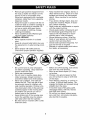 5
5
-
 6
6
-
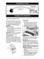 7
7
-
 8
8
-
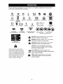 9
9
-
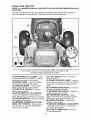 10
10
-
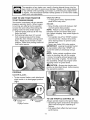 11
11
-
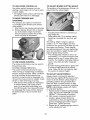 12
12
-
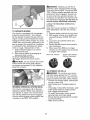 13
13
-
 14
14
-
 15
15
-
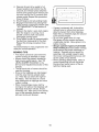 16
16
-
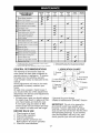 17
17
-
 18
18
-
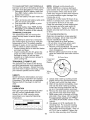 19
19
-
 20
20
-
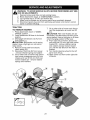 21
21
-
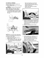 22
22
-
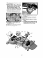 23
23
-
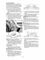 24
24
-
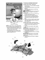 25
25
-
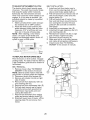 26
26
-
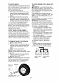 27
27
-
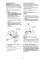 28
28
-
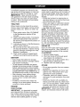 29
29
-
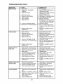 30
30
-
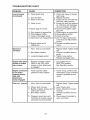 31
31
-
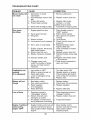 32
32
-
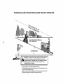 33
33
-
 34
34
-
 35
35
-
 36
36
-
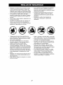 37
37
-
 38
38
-
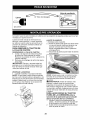 39
39
-
 40
40
-
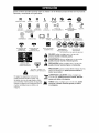 41
41
-
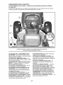 42
42
-
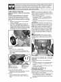 43
43
-
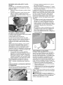 44
44
-
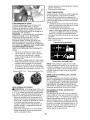 45
45
-
 46
46
-
 47
47
-
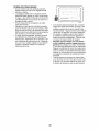 48
48
-
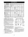 49
49
-
 50
50
-
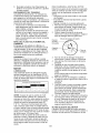 51
51
-
 52
52
-
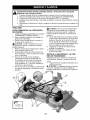 53
53
-
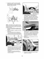 54
54
-
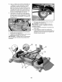 55
55
-
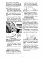 56
56
-
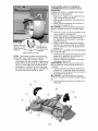 57
57
-
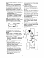 58
58
-
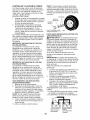 59
59
-
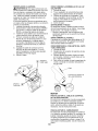 60
60
-
 61
61
-
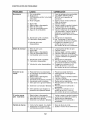 62
62
-
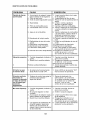 63
63
-
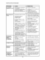 64
64
-
 65
65
-
 66
66
-
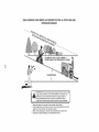 67
67
-
 68
68


Southern States 96042001300 El manual del propietario
- Categoría
- Tractor
- Tipo
- El manual del propietario