
FPA400 INSTRUCTION MANUAL
Scan for easy install video
san.us/260
We’ll Make It Stress-Free
If you have any questions along the way, just give us a call.
1-888-333-9952. We’re ready to help!

2
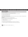
IMPORTANT SAFETY INSTRUCTIONS – SAVE THESE INSTRUCTIONS – PLEASE READ ENTIRE MANUAL PRIOR TO USE
Before You Begin
Please check the following items:
Any accessories you plan to use do not exceed the specifi ed weight limit.
The wall you chose to mount your shelf is wood stud, drywall, solid concrete, or concrete block.
You read and understand these directions.
You have the tools needed for installation.
If you do not understand these instructions, or have doubts about the safety of the installation, assembly or use of this product, contact
Customer Service or call a qualifi ed contractor.
CAUTION: Avoid potential personal injuries and property damage!
● Do not use this product for any purpose not explicitly specifi ed by manufacturer.
● Do not place objects heavier than 15 lb (6.8 kg) on shelf.
● Do not place a TV on shelf.
● Do not allow children to climb or hang on shelf.
● Manufacturer is not responsible for damage or injury caused by incorrect assembly or use.
● This product is designed for use in wood stud, drywall, solid concrete and concrete block walls.
NOTE: Para instrucciones en Español, ver páginas 16-19

3
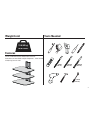
Tools Needed
10 mm
(3/8 in.)
11 mm
(7/16 in.)
3 mm
(1/8 in.)
10 mm
(3/8 in.)
Weight Limit
15 lb (6.8 kg)
DO NOT EXCEED!
Features
Can be mounted to drywall, wood stud, or concrete.
Stackable to accommodate multiple components - not to exceed
15 lb (6.8 kg) on each shelf.

4
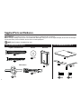
NOTE: Not all hardware included will be used.
Supplied Parts and Hardware
WARNING: This product contains small items that could be a choking hazard if swallowed.
Before starting assembly, verify all parts are included and undamaged. If any parts are missing or damaged, do not return the damaged
item to your dealer; contact Customer Service. Never use damaged parts!
Parts and Hardware for STEP 1 Parts and Hardware for STEP 2
Lag Bolts and Wall Screws Washer Wall Plate
Wall Anchors
01
02
04
05
09
10 11
03
(1)
(3)
(3)
(1)
(1)
(1)
(1)
(2)
(2)
(1)
(1)
06
07
08
1/4 x 2 ½ in.
#8 x 2 in.
M5 x 20
M5 x 6
M3

5
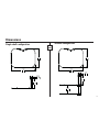
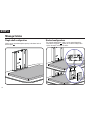
Dimensions
Single shelf confi guration
1.11
28.1
6.3
159.9
12.50
317.5
17.00
431.8
Stacked confi guration
1.11
28.1
5.11
129.8
6.3
159.9
12.50
317.5
17.00
431.8
in.
[mm]

6
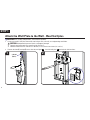
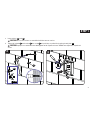
Attach the Wall Plate to the Wall
-
Wood Stud Option
1 2
≤ 16 mm
(5/8 in.)
06
STEP 1
IMPORTANT: For stacking configurations, stack from the top down.
1. Locate your stud(s). Verify the center of the stud using an awl, a thin nail, or an edge to edge stud finder.
CAUTION: Avoid potential personal injuries and property damage!
● Drywall covering the wall must not exceed 16 mm (5/8 in.).
● Minimum wood stud size: common 51 x 102 mm (2 x 4 in.) nominal 38 x 89 mm (1½ x 3½ in.).
2. Remove the front (F) and top (T) covers from the wall plate
06
. Level the wall plate
06
and mark the hole locations.
(F)
(T)

7
3 4
06
63.5 mm
(2½ in.)
3 mm
(1/8 in.)
02
01
03
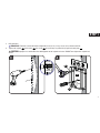
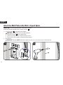
STEP 1
3. Drill pilot holes.
IMPORTANT: Pilot holes must be drilled to a depth of 63.5 mm (2½ in.), using a 3 mm (1/8 in.) diameter drill bit.
4. Tighten the lag bolt
01
and washer
03
the screw
02
only until they are pulled firmly against the wall plate
06
.
CAUTION: Improper use could reduce the holding power of the lag bolt and screw. DO NOT over-tighten the lag bolt and
screw.

8
1 2
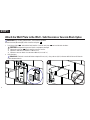
STEP 1
Attach the Wall Plate to the Wall -
Solid Concrete or Concrete Block Option
IMPORTANT: For stacking configurations, stack from the top down.
Remove the front (F) and top (T) covers from the wall plate
06
.
1. Level the wall plate
06
and mark the hole locations. Level the wall plate
06
and mark the hole locations.
CAUTION: Avoid potential personal injuries and property damage!
● Mount the wall plate
06
directly onto the concrete surface
● Minimum solid concrete thickness: 203mm (8 in.)
● Minimum concrete block size: 203 x 203 x 406 mm (8 x 8 x 16 in.)
2. Drill pilot holes.
IMPORTANT: Pilot holes must be drilled to a depth of 75 mm (3 in.), using a 10 mm (3/8 in.) diameter drill bit. Never drill into the
mortar between blocks.
06
(F)
(T)

9
3. Insert anchors
04
and
05
.
CAUTION: Be sure the anchors are seated flush with the concrete surface.
4. Tighten the lag bolt
01
and washer
03
the screw
02
only until they are pulled firmly against the wall plate
06
.
CAUTION: Improper use could reduce the holding power of the lag bolt and screw. DO NOT over-tighten the lag bolt and
screw.
3
4
06
04
05
03
01
02
04
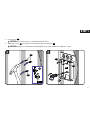
STEP 1

10
1 2
06
Attach the Wall Plate to the Wall -
Drywall Option
STEP 1
IMPORTANT: For stacking configurations, stack from the top down.
Remove the front (F) and top (T) covers from the wall plate
06
.
1. Level the wall plate
06
and mark the hole locations.
CAUTION:
Avoid potential injuries or property damage!
● Mount the wall plate
06
directly onto the wall.
● Drywall covering the wall must not exceed 13mm (1/2 in.).
● Do not install anchors into the seam between drywall pieces.
2. Drill pilot holes.
IMPORTANT: Pilot holes MUST be drilled to a depth of 38 mm (1½ in.) using a 10 mm (3/8 in.) diameter drill bit.
(F)
(T)

11
3 4
06
02
02
02
04
STEP 1
3. Insert anchors
04
.
CAUTION: Be sure the anchors are seated flush with the surface.
4. Tighten the screws
02
only until they are pulled firmly against the wall plate
06
.
CAUTION: Improper use could reduce the holding power of the screw. DO NOT over-tighten the screws.
04
04

12
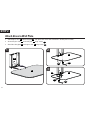
1. Slide the glass shelf
07
into the wall plate
06
. Line up the holes in the shelf to the holes in the wall plate as shown.
2. Secure the glass shelf
07
to the wall plate
06
using screws
10
.
3. Attach the safety plate
08
to the glass shelf
07
using screws
11
.
1 2
3
STEP 2
Attach Glass to Wall Plate
09
09
10
11
07
07
07
06
08

13

14
Manage Cables
Single shelf configuration
Cables can be routed through the opening in the lower back of
the wall plate
06
.
For stacked configurations, cables can be routed through the
inside of the wall plates
06
. When you are done routing cables
replace the top (T) and front (F) covers.
Stacked configurations
STEP 3
06
(F)
(T)

15

16
ESPAÑOL
INSTRUCCIONES DE SEGURIDAD IMPORTANTES. CONSÉRVELAS. LEA TODO EL MANUAL ANTES DE UTILIZAR ESTE PRODUCTO.
Antes de comenzar
Cerciórese de:
que los accesorios que planifi ca usar no excedan el límite de peso especifi cado;
que la pared escogida para el montaje de su repisa sea una pared de montantes de madera, yeso, hormigón sólido o bloques de cemento;
haber leído y comprendido estas instrucciones;
tener todas las herramientas necesarias para la instalación.
Si no entiende las instrucciones o si tiene dudas acerca de la seguridad de la instalación, del ensamblado o del uso del producto, contáctese con
el servicio de atención al cliente o llame a un técnico califi cado.
PRECAUCIÓN: Evite posibles lesiones personales y daños materiales.
● No utilice este producto para ningún otro propósito que no sea el explícitamente especifi cado por el fabricante.
● No coloque objetos que superen los 6.8 Kg. (15 libras) en la repisa.
● No coloque un televisor en la repisa.
● No permita que los niños se trepen o se cuelguen de la repisa.
● El fabricante no se responsabiliza por ningún daño o lesión resultante del montaje incorrecto o del uso indebido.
● Este producto fue diseñado para su uso en paredes de montantes de madera, yeso, hormigón sólido y bloques de cemento.
Herramientas necesariasPeso límite
Descripción
Puede instalarse en paredes de yeso, montantes de madera o cemento.
Apilable para ubicar varios componentes - no supere las 15 libras (7 Kg.) en cada repisa.

17
ESPAÑOL
NOTA: No todos los elementos de sujeción incluidos deberán utilizarse.
Piezas y elementos de sujeción suministrados
ADVERTENCIA: Este producto contiene piezas pequeñas que, si fuesen tragadas, podrían producir asfixia.
Antes de iniciar el ensamblaje, compruebe que todas las piezas estén incluidas y en buenas condiciones. Si faltan piezas o alguna está dañada,
no devuelva el artículo al distribuidor; póngase en contacto con el servicio de atención al cliente. Nunca utilice piezas deterioradas.
Dimensiones
Confi guración con una sola repisa
Confi guración apilada
Fijar la placa mural a la pared
-
Opción para montantes de madera
PASO 1
IMPORTANTE: Para las confi guraciones apiladas, comience a apilar de arriba a abajo.
1. Localice el o los montantes. Verifi que el centro del montante con un punzón o un clavo delgado, o bien utilice un detector de bordes de montantes.
PRECAUCIÓN: Evite posibles lesiones personales y daños materiales.
● El material que recubre la pared no debe exceder los 16 mm (5/8 pulgada).
● Tamaño mínimo del montante de madera: común 51 mm x 102 mm (2 x 4 pulgadas) (nominal 38 mm x 89 mm [1½ x 3½ pulgadas]).
2. Retire las cubiertas frontal (F) y superior (T) de la placa mural
06
. Nivele la placa mural
06
y marque la ubicación de los orifi cios.
3. Realice los orifi cios guía.
IMPORTANTE: Los orifi cios guía deben realizarse con una mecha de 3 mm (1/8 pulgada) de diámetro, hasta una profundidad de 63,5 mm
(2,5 pulgadas).
4. Ajuste el tornillo tirafondo
01
, la arandela
03
y el tornillo
02
solamente hasta que queden fi rmes contra la placa mural
06
.
PRECAUCIÓN: El uso indebido podría reducir la capacidad de retención del tornillo tirafondo y el tornillo. NO ajuste en exceso el tornillo
tirafondo y el tornillo.

18
ESPAÑOL
3. Inserte los anclajes
04
y
05
.
PRECAUCIÓN: Cerciórese de que los anclajes hayan quedado nivelados respecto de la superfi cie de hormigón.
4. Ajuste el tornillo tirafondo
01
, la arandela
03
y el tornillo
02
solamente hasta que queden fi rmes contra la placa mural
06
.
PRECAUCIÓN: El uso indebido podría reducir la capacidad de retención del tornillo tirafondo y el tornillo. NO ajuste en exceso el tornillo
tirafondo y el tornillo.
Fijar la placa mural a la pared -
Opción para pared de yeso
IMPORTANTE: Para las confi guraciones apiladas, comience a apilar de arriba a abajo.
Retire las cubiertas frontal (F) y superior (T) de la placa mural
06
.
1. Nivele la placa mural
06
y marque la ubicación de los orifi cios.
PRECAUCIÓN:
Evite lesiones personales y daños materiales.
● Instale la placa mural
06
directamente sobre la pared.
● El material que recubre la pared no debe exceder los 13 mm (1/2 pulgada).
● No instale anclajes en la juntura entre las piezas de yeso.
Fijar la placa mural a la pared -
Opción para hormigón sólido o bloques de cemento
IMPORTANTE: Para las confi guraciones apiladas, comience a apilar de arriba a abajo.
Retire las cubiertas frontal (F) y superior (T) de la placa mural
06
.
1. Nivele la placa mural
06
y marque la ubicación de los orifi cios. Nivele la placa mural
06
y marque la ubicación de los orifi cios.
PRECAUCIÓN: Evite posibles lesiones personales y daños materiales.
● Instale la placa mural
06
directamente sobre la superficie de hormigón.
● Espesor mínimo del hormigón: 203 mm (8 pulgadas)
● Tamaño mínimo del bloque de cemento: 203 x 203 x 406 mm (8 x 8 x 16 pulgadas)
2.
Realice los orifi cios guía.
IMPORTANTE: Los orifi cios deben realizarse con una mecha de 10 mm (3/8 pulgada) de diámetro, hasta una profundidad de 75 mm (3 pulgadas).
Nunca perfore el cemento que une los bloques.

19
ESPAÑOL
2. Realice los orifi cios guía.
IMPORTANTE: Los orifi cios guía DEBEN realizarse con una mecha de 10 mm (3/8 pulgada) de diámetro hasta una profundidad de 38 mm
(1½ pulgadas).
3. Inserte los anclajes
04
.
PRECAUCIÓN: Cerciórese de que los anclajes hayan quedado nivelados respecto de la superfi cie.
4. Ajuste los tornillos
02
solamente hasta que queden fi rmes contra la placa mural
06
.
PRECAUCIÓN: El uso indebido podría reducir la capacidad de retención del tornillo. NO ajuste en exceso los tornillos.
PASO 2
1. Deslice la repisa de vidrio
07
en la placa mural
06
. Alinee los orifi cios de la repisa con los orifi cios de la placa mural tal como se ilustra.
2. Fije la repisa de vidrio
07
a la placa mural
06
con tornillos
10
.
3. Coloque la placa de seguridad
08
a la repisa de vidrio
07
usando tornillos
11
.
Fijar el vidrio a la placa mural
PASO 3
Organización de cables
Configuración con una sola repisa
Los cables pueden pasarse por la abertura que se encuentra en la
parte inferior trasera de la placa mural
06
.
Para las confi guraciones apiladas, los cables pueden pasarse por
dentro de las placas murales
06
. Cuando termine de pasar los cables
vuelva a colocar las cubiertas superior (T) y frontal (F).
Configuraciones apiladas

6902-002049 02
Milestone AV Technologies and its a liated corporations and subsidiaries (collectively, “Milestone”), intend to make this manual accurate and complete. However,
Milestone makes no claim that the information contained herein covers all details, conditions, or variations. Nor does it provide for every possible contingency in
connection with the installation or use of this product. The information contained in this document is subject to change without notice or obligation of any kind.
Milestone makes no representation of warranty, expressed or implied, regarding the information contained herein. Milestone assumes no responsibility for accuracy,
completeness or su ciency of the information contained in this document.
©2013 Milestone AV Technologies. All rights reserved. Sanus is a division of Milestone.
All other brand names or marks are used for identifi cation purposes and are trademarks of their respective owners.
Thank you for choosing Sanus VuePoint! Please take a moment to let us know how we did:
SANUS • 6436 City West Parkway • Eden Prairie, MN 55344 USA
Call us: 1-888-333-9952
UK: 0800 056 2853
Email us: [email protected] Leave a review: vuepoint.sanus.com
Find us on Facebook: SANUS Follow us on Twitter @sanussystems
-
 1
1
-
 2
2
-
 3
3
-
 4
4
-
 5
5
-
 6
6
-
 7
7
-
 8
8
-
 9
9
-
 10
10
-
 11
11
-
 12
12
-
 13
13
-
 14
14
-
 15
15
-
 16
16
-
 17
17
-
 18
18
-
 19
19
-
 20
20


en otros idiomas
- English: Sanus FPA400 User manual
Artículos relacionados
-
Sanus SOA-AVS1 Guía de instalación
-
-
-
-
-
-
-
-
-