Champion Power Equipment 100237 Manual de usuario
- Categoría
- Generadores de poder
- Tipo
- Manual de usuario
Este manual también es adecuado para

REV 100136-20200110
Danger: Not intended for use in critical life support application.
Danger: Generator must be installed and operated outdoors only.

Have questions or need assistance?
Do not return this product to the store!
WE ARE HERE TO HELP!
Visit our website:
www.championpowerequipment.com
for more info:
• Product Info & Updates
• Frequently Asked Questions
• Tech Bulletins
• Product Registration
– or –
Call our Customer Care Team Toll-Free at:
1-877-338-0999
*We are always working to improve our products. Therefore, the enclosed product may differ slightly from the image on the cover.
This manual must be used with Champion Power Equipment (CPE) manuals:
• Installation Manual, Part No. 101951
• Transfer Switch Manual, Part No. 101948
It is also recommended to refer to the reference materials list on page 16 of
the Installation Manual.
WARNING
Cancer and Reproductive Harm – www.P65Warnings.ca.gov
DISCLAIMERS
All information, illustrations and specifications in this manual are based on the latest information
available at the time of publishing. The illustrations used in this manual are intended as representative
reference views only. Products are under a continuous improvement policy. Thus, information,
illustrations and/or specifications to explain and/or exemplify a product, service or maintenance
improvement may be changed at any time without notice.
ALL RIGHTS RESERVED
No part of this publication may be reproduced or used in any form by any means – graphic, electronic
or mechanical, including photocopying, recording, taping or information storage and retrieval systems –
without the written permission of Champion Power Equipment (CPE).

3
Model 100237
CONTENTS
Part No. 101950
CONTENTS
Home Standby Generator ................................................5
Parts Included .................................................................5
INTRODUCTION ....................................................6
General Information, Standards and Codes ....................6
SAFETY ................................................................7
Safety Symbol Definitions ............................................... 7
Warnings .................................................................7
Mandatory Actions ...................................................8
Installation Hazards ........................................................8
Before Starting ................................................................9
Operating Hazards ........................................................... 9
Accidental Starting .......................................................10
Carbon Monoxide Hazards ............................................10
Electrical Shock Hazards ..............................................11
Fire/Explosion Hazards .................................................11
Burn Hazards ................................................................. 11
Entanglement Hazards ..................................................12
Battery Hazards .............................................................12
Safety labels .................................................................. 12
Safety labels and hang tags ...................................13
Safety label and Hang tag locations .......................14
GENERAL INFORMATION ....................................15
Component Identification – 14 kW Generator ..............15
Component Identification – Engine ..............................16
Control Panel ................................................................16
Main Circuit Breaker ..............................................16
Exercise Switch .....................................................16
Set Exercise Time ..................................................17
Hour Meter ............................................................17
Engine Control Module ...........................................17
Reset fault Code(s) ................................................. 17
ATS Control Module ................................................18
Battery Charger .............................................................19
Emission Requirements ................................................19
Specifications ................................................................ 20
Fuel System ...................................................................21
Battery Requirements ...................................................21
Battery Charging ...........................................................21
Model and Serial Number .............................................21
OPERATION ........................................................22
Enclosure and Access ...................................................22
Pre-Start Checklist ........................................................ 22
Turning OFF the Generator ............................................22
MAINTENANCE ...................................................23
Scheduled Maintenance Chart ...................................... 23
Engine Oil ......................................................................23
Engine Oil Requirements ........................................23
Checking the Engine Oil Level ................................23
Changing the Engine Oil ......................................... 24
Inspect and Clean Engine Air Cleaner ..........................25
Spark Plug .....................................................................25
Battery Maintenance ..................................................... 26
Corrosion Protection .....................................................26
Maintenance After Submersion ....................................26
Storage ..........................................................................26
Return to Service after Storage ....................................27
Engine parts ..........................................................28
Enclosure and assemblies ......................................32
Alternator and Exhaust System ...............................36
Control Panel .........................................................38
Wiring Diagram ...................................................... 40

4
Model 100237
CONTENTS
Part No. 101950
TROUBLESHOOTING ........................................... 41
Troubleshooting HSB ..................................................... 41
ADDITIONAL INFORMATION ............................... 43
Identify/Select Standby Circuits ...................................43
Surge Protection ...........................................................43
Customer Familiarization Summary .............................44
HSB, ATS Model & Serial Reference ATS Back-up
Circuits ..........................................................................45
Maintenance and Service Record .................................46

Model 100237
INTRODUCTION
5
Part No. 101950
Congratulations on your purchase of a Champion Power
Equipment (CPE) home standby generator. This generator is
designed and engineered in the USA to exacting standards of the
North American market. This engine-powered generator meets
all Environmental Protection Agency (EPA) Phase 3 requirements
and is approved by CETLUS as tested to UL2200 and CSA22.2
No. 100 in both the USA and Canada.
With proper use and maintenance, this generator will provide
years of satisfying service.
The Champion Staff,
Champion Power Equipment
12039 Smith Ave.
Santa Fe Springs, CA 90670
Toll-free: 1-877-338-0999
Mon-Fri 8:30 AM – 5:00 PM (PST/PDT)
www.championpowerequipment.com
HOME STANDBY GENERATOR
This home standby generator is intended exclusively for outdoor
installation. This generator will operate using either liquified
petroleum gas (LPG) or natural gas (NG).
This generator is designed to supply typical home load such as:
• Induction motors – sump pumps, refrigerators, air
conditioners, furnaces
• Electronic items – televisions, computers
• Household lighting
• Microwaves
• This generator is not intended for use in critical life support
applications.
Proper sizing of the generator is required to ensure proper
operation of appliances. Some appliances require additional
wattage to start and must be considered.
PARTS INCLUDED
Your HSB ships with the following:
• Operator’s Manual
• Installation Manual
• Oil Drain Pan
• Flexible Fuel Line
• HSB Enclosure Keys
• Battery Cable Connection
• LPG Low-speed and Main Converting Jets
• Jet Change Tool
• Lock Nut M6
• Washer, Ø6
• Flange bolt, M6 x 15

Model 100237
INTRODUCTION
6
Part No. 101950
GENERAL INFORMATION,
STANDARDS AND CODES
The following information related to General Information and
Standards was gathered from the list of publications related
to installing the HSB generator. A multitude of other materials
related to generators were also used concerning common
practice, knowledgeable installation practices, certified
electrical experience and work related experiences. This
information is not all inclusive and the manufacturer strongly
recommends the owner and installer become familiar with all
pertinent codes, standards and regulations. Always check for
the latest publications date to ensure you are current. Have
only a qualified/certified electrician or installation technician
who is knowledgeable about applicable codes, standards and
regulations install and service the generator.
NFPA NO. 30, FLAMMABLE AND CONBUSTIBLE LIQUID
CODE
National Fire Protection Association
470 Atlantic Avenue, Boston, MA. 02210
NFPA NO. 37, STATIONARY COMBUSTION ENGINES AND
GAS TURBINES
National Fire Protection Association
470 Atlantic Avenue, Boston, Ma. 02210
NFPA NO. 76A, ESSENTIAL ELECTRICAL SYSTEMS FOR
HEALTH CARE FACILITIES
National Fire Protection Association
470 Atlantic Avenue, Boston, Ma. 02210
NFPA NO. 54, NATIONAL FUEL GAS CODE
National Fire Protection Association
470 Atlantic Avenue, Boston, Ma. 02210
NFPA NO. 58, AMERICAN NATIONAL STANDARD FOR
STORAGE AND HANDLING OF LIQUID PETROLEUM GAS
National Fire Protection Association
470 Atlantic Avenue, Boston, Ma. 02210
NFPA NO. 70, NFPA HANDBOOK OF ELECTRIC CODE
National Fire Protection Association
470 Atlantic Avenue, Boston, Ma. 02210
ARTICLE X, NATIONAL BUILDING CODE
American Insurance Association
85 John Street, New York, N.Y. 10038
AGRICULTURAL WIRING HANDBOOK
Food and Energy Council
909 University Avenue, Columbia, Mo. 65201
ASAE EP-3634, INSTALLATION AND MAINTENANCE OF
FARM STANDBY ELECTRICAL SYSTEMS
American Society of Agricultural Engineers
2950 Niles Road, St. Joseph, Mi. 49085

7
Model 100237
SAFETY
Part No. 101950
!
This is the safety alert symbol. It is used to alert
you to potential physical injury hazards. Obey all
safety messages that follow this symbol to avoid
possible injury or death.
The words DANGER, WARNING, CAUTION and NOTICE are used
throughout this manual to highlight important information.
!
DANGER
Indicates a hazardous situation that, if not avoided, will
result in death or serious injury.
!
WARNING
Indicates a hazardous situation that, if not avoided, could
result in death or serious injury.
!
CAUTION
Indicates a hazardous situation that, if not avoided, could
result in minor or moderate injury.
NOTICE
Indicates a situation that can cause damage to the
equipment, personal property and/or the environment, or
cause the equipment to operate improperly.
OTE: N Indicates a procedure, practice or condition that
should be followed in order for the generator to
function in the manner intended.
SAFETY SYMBOL DEFINITIONS
!
Black hazard pictorial on yellow
equilateral triangle enclosed by black
triangular band
Warns that hazard exists and describes
its nature and/or consequences
Black hazard pictorial on white circle
enclosed by red circular band with red
diagonal bar
Depicts action NOT to be taken or
action to be stopped in order to avoid
hazard
White hazard pictorial on blue circle
Depicts action to be taken in order to
avoid hazard
WARNINGS
!
Safety alert symbol
Asphyxiation hazard
Electrical shock hazard
Entanglement hazard
Fire hazard

8
Model 100237
SAFETY
Part No. 101950
Explosion hazard
Burn hazard
Sever hazard (rotating blade)
Crush hazard (top)
MANDATORY ACTIONS
Read manufacturer’s instructions
Wear eye protection
Wear personal protective equipment
Do not leave tools in the area
INSTALLATION HAZARDS
!
WARNING
!
Have only a qualified electrician or
installation technician who is familiar
with applicable codes, standards and
regulations install and service the
generator.
ALWAYS comply with local, state and national electrical and
building codes when installing the generator. NEVER alter
the recommended installation in a way that would render
the unit noncompliant with these codes.
ALWAYS comply with regulations that Occupational Safety
and Health Administration (OSHA) has established.
ENSURE the generator is installed following the
manufacturer’s instructions.
NOTICE
Before welding components on the generator, contact
Champion Power Equipment for recommended welding
instructions.
!
WARNING
!
Not intended for use in critical life
support applications.

9
Model 100237
SAFETY
Part No. 101950
BEFORE STARTING
!
CAUTION
Before starting, operating and
maintaining this generator, be sure to
read and understand the content and
safety messages in this manual.
The operator is responsible for safe operation and
maintenance of the generator. Be sure all potential users
of the generator also understand these instructions. If any
portion of this manual is not understood, contact your dealer
for assistance before operating the generator.
The operator is responsible for performing all safety checks,
making sure all maintenance is properly performed and
making sure the generator is periodically checked by the
dealer.
Inspect the generator regularly. Contact your dealer if
repairs are needed.
NEVER climb or step on any part or components of the
generator. Doing so may result in injury and cause leaking
fuel and exhaust.
OPERATING HAZARDS
!
WARNING
!
ALWAYS operate the generator following
the manufacturer’s instructions.
Operating the generator imprudently,
neglecting maintenance or being
careless can result in injury or possible
death.
DO NOT allow children or unqualified persons to operate or
service the generator.
NEVER operate the generator with the covers open. Operate
the generator only with the covers closed and secured in
place. NEVER leave the covers unlocked.
Remain alert at all times when working on the generator.
NEVER work on the generator when physically or mentally
fatigued.
Never operate the generator while under the influence of
alcohol or drugs. Their effects on vision and judgment make
operating a generator dangerous.

10
Model 100237
SAFETY
Part No. 101950
ACCIDENTAL STARTING
!
WARNING
ALWAYS prevent the generator from starting while the
covers are open. The generator may crank and start at any
time without notice. Follow these steps in order:
1. Turn the exercise switch to the OFF position.
2. Switch the main circuit breaker to the OFF position.
3. Turn the ATS control module to the OFF position.
4. Turn the engine control module switch to the OFF
position.
5. Disconnect the NEGATIVE, NEG or (-) battery cable
first, and then remove the POSITIVE, POS or (+)
battery cable.
To return the generator to service, follow these steps in
order:
1. Connect the POSITIVE, POS or (+) battery cable first,
and then connect the NEGATIVE, NEG or (-) battery
cable.
2. Turn the engine control module switch to the ATS
position.
3. Turn the ATS control module switch to the AUTO
position.
4. Switch the main circuit breaker to the ON position.
5. Turn the exercise switch to the ON position.
CARBON MONOXIDE HAZARDS
!
DANGER
Generator exhaust contains carbon
monoxide, a colorless, odorless,
poisonous gas. Breathing carbon
monoxide will cause nausea, dizziness,
fainting or death. If you start to
feel dizzy or weak, get to fresh air
immediately.
• The generator must be installed and operated outdoors
only. NEVER install the generator where exhaust fumes
could seep inside or be drawn into a potentially occupied
building through windows, air intake vents or other
openings.
• Avoid breathing exhaust fumes when near an operating
generator.
• NEVER alter or add to the exhaust system or do anything
that might render the system unsafe or in noncompliance
with applicable codes, standards, laws and regulations.
• Install a battery-operated carbon monoxide detector
on each level of any building adjacent to the generator
following the manufacturer’s instructions.
• NEVER permit even partial blockage of engine cooling
ventilation air. Doing so can seriously affect safe
operation of the generator.
Carbon monoxide poisoning symptoms include but are not
limited to the following:
• Light-headedness, dizziness
• Physical fatigue, weakness in joints and muscles
• Sleepiness, mental fatigue, inability to concentrate or speak
clearly, blurred vision
• Stomachache, vomiting, nausea
Carbon monoxide poisoning is possible if someone is
experiencing any of these symptoms. Seek fresh air immediately.
DO NOT sit, lie down or fall asleep. Alert others to the possibility
of carbon monoxide poisoning. If the affected person does
not improve within minutes of breathing fresh air, call 911
immediately.

11
Model 100237
SAFETY
Part No. 101950
ELECTRICAL SHOCK HAZARDS
!
WARNING
Use extreme caution when near the
generator while it is operating. The
generator produces dangerous voltage.
• Avoid contact with bare wires, terminals and connections
while the generator is operating.
• ALWAYS stand on an insulated dry surface to reduce
shock hazard if work must be done on an operating
generator.
• NEVER wear jewelry that can conduct electricity when
working on the generator.
• NEVER handle any kind of electrical device while hands
or feet are wet, while standing in water or while barefoot.
• Proper earth grounding of the frame and external
electrical conductive components is required by the
National Electrical Code (NEC). State and local codes for
proper grounding may also apply.
• Avoid direct contact with an electric shock victim.
Immediately shut down the source of electrical power. If
this is not possible, attempt to free the victim from the
live conductor using a nonconducting item such as a dry
board or rope. If the victim is unconscious, apply first aid
and call 911 immediately.
FIRE/EXPLOSION HAZARDS
!
WARNING
NG and LPG are extremely explosive.
• NEVER allow any flames or smoke near the fuel system.
• Wipe up any oil spills immediately.
• NEVER allow any combustible materials to be near the
generator or to be left in the generator compartment.
• ALWAYS keep the surrounding area near the generator
clean and free of debris.
• Be sure to properly purge the fuel lines and leak-test
according to applicable codes before placing the
generator in service.
• Be sure to regularly inspect the fuel system for leaks.
NEVER operate the generator if a fuel leak is present.
• Install a fire extinguisher near the generator. Keep it
properly charged and be familiar with its use. An ABC
rated National Fire Protection extinguisher is appropriate
for use on standby electric systems. Contact your local
fire department with any questions concerning the fire
extinguisher.
BURN HAZARDS
!
WARNING
ALWAYS allow hot surfaces to cool to
the touch. Running engines produce
heat. Severe burns can occur on
contact.
• DO NOT touch hot surfaces.
• Avoid contact with hot exhaust components and gases.

12
Model 100237
SAFETY
Part No. 101950
ENTANGLEMENT HAZARDS
!
WARNING
Use extreme caution when near rotating
parts. Rotating parts can entangle
hands, feet, hair, clothing and/or
accessories. Traumatic amputation or
severe laceration can result.
• Keep hands and feet away from rotating parts.
• Tie up long hair and remove jewelry.
• Operate equipment with guards in place.
• DO NOT wear loose-fitting clothing, dangling drawstrings
or items that could become caught.
BATTERY HAZARDS
!
WARNING
Always read and comply with
the battery manufacturer’s
recommendations for procedures
concerning proper battery use and
maintenance.
Batteries contain sulfuric acid and
generate explosive mixtures of
hydrogen and oxygen gases. Keep
any device that may cause sparks or
flames away from the battery to prevent
explosion.
Always wear protective glasses or
goggles and protective clothing when
working with batteries. You must follow
the battery manufacturer’s instructions
on safety, maintenance and installation
procedures.
SAFETY LABELS
!
WARNING
!
All safety labels must be legible to alert
personnel of safety hazards.
• Replace any illegible or missing label immediately.
Missing safety labels must be replaced in their original
position before the generator is operated.
• DO NOT operate the generator if there are missing or
badly worn safety labels.

13
Model 100237
SAFETY
Part No. 101950
SAFETY LABELS AND HANG TAGS
# LABEL DESCRIPTION PART NO.
1
Burn Hazard DO NOT
touch hot surfaces. Allow
the engine and alternator
to cool to the touch
before servicing.
Danger de brulure NE
TOUCHEZ PAS les
surfaces chaudes.
Laissez le moteur et
l’alternateur devenir froid
au toucher avant
d’intervenir.
Riesgo de quemaduras
NO toque las superficies
calientes. Deje que el
motor y el alternador se
enfríen para tocarlos
antes de realizarles el
mantenimiento.
100794
!
!
!
100789
!
!
!
Electrical Shock Hazard ALWAYS
close and lock generator covers before
operating. The generator produces
dangerous voltage.
Risque de choc électrique Fermez et
verrouillez TOUJOURS les capots de
groupe électrogène avant d’utiliser le
groupe. Le groupe électrogène génère
des tensions dangereuses.
Riesgo de descarga eléctrica
SIEMPRE cierre y trabe las tapas del
generador antes de ponerlo en
funcionamiento. El generador produce
un voltaje peligroso.
101045
!
!
!
Electrical Shock Hazard
Do not remove this access panel. The panel
should only be removed by an authorized
Service Dealer or a qualified electrician;
high voltage inside.
Risque de choc électrique
Riesgo de descarga eléctrica
N’enlevez pas ce panneau d’accès.
Le panneau ne devrait être enlevé que par
un concessionnaire d’entretien agréé ou un
électricien qualifié ; haute tension à l’intérieur.
No remueva este tablero de acceso. El tablero
sólo deberá s
er removido por un distribuidor
de servicio autorizado o un electricista
calificado; alto voltaje al interior.
!
!
!
101051
Burn Hazard DO NOT touch hot
surfaces. Avoid contact with
exhaust components and gases.
Risque de brûlure NE touchez
PAS les surfaces chaudes. Evitez
le contact avec les composants et
les gaz d’échappement.
Riesgo de quemaduras NO toque
las superficies calientes. Evite el
contacto con los componentes de
escape y gases.
1
101500
101499
101045
101051 100789
100794
2
3
6
4 5
!
!
!
Burn Hazard DO NOT touch hot
surfaces. Avoid contact with
exhaust components and gases.
Risque de brûlure NE touchez
PAS les surfaces chaudes. Evitez
le contact avec les composants et
les gaz d’échappement.
Riesgo de quemaduras NO toque
las superficies calientes. Evite el
contacto con los componentes de
escape y gases.
101500
Fire Hazard ALWAYS keep the surrounding
area near generator clean and free of debris
and/or dry vegetation. The generator may
create sparks while operating.
Risque d’incendie Nettoyez TOUJOURS la
surface à proximité du groupe électrogène et
enlevez les débris et/ou la végétation sèche.
Le groupe électrogène peut générer des
étincelles pendant son fonctionnement.
Riesgo de incendio SIEMPRE mantenga el
área circundante cerca del generador limpia y
libre de escombros y/o vegetación seca. El
generador puede crear chispas mientras está
en funcionamiento.
!
!
!
!
Poisonous Gas Hazard Generator exhaust
contains carbon monoxide. Breathing carbon
monoxide will cause nausea, dizziness, and
fainting, and it may cause death.
Risque d’empoisonnement par le gaz Les gaz
d’échappement de groupe électrogène contiennent
du monoxyde de carbone. Si l’on respire du
monoxyde de carbone, ceci peut provoquer des
nausées, un évanouissement et une perte de
conscience, et ceci peut provoquer la mort.
Riesgo de gas venenoso El escape del
generador contiene monóxido de carbono. Aspirar
monóxido de carbono causará náuseas, mareos,
desvanecimiento y hasta la muerte.
!
!
Read Operator’s Manual Read,
understand and follow all safety
messages in Installation and Operator’s
manuals.
Lisez le manuel d’utilisation Lisez,
comprenez bien et respectez tous les
messages de sécurité dans les manuels
d’installation et d’utilisation.
Lea el manual del operador Lea,
comprenda y siga todos los mensajes
de seguridad en los manuales de
instalación y del operador.
!
!
!
!
!
!
Starting Hazard The generator may crank and
start at any time without notice. Prevent the
generator from starting while the covers are open.
See the safety section of the operator’s manual for
further detail.
Risque au démarrage Le groupe électrogène
peut tourner et démarrer à tout moment sans
préavis. Ne démarrez pas le groupe électrogène
lorsque les capots sont ouverts. Consultez la
section sécurité du manuel d’utilisation pour plus
de détail.
Riesgo de inicio El generador puede encenderse
y ponerse en marcha en cualquier momento sin
previo aviso. Evite que el generador se ponga en
marcha mientras las tapas están abiertas. Vea la
sección de seguridad en el manual del operador
para más detalles.
101499
Explosion Hazard Battery gases are explosive.
Keep sparks and flames away from the battery
compartment.
Risque d’explosion Les gaz dégagés par la
batterie peuvent exploser. Ecartez les étincelles
et les flammes du compartiment batterie.
Riesgo de explosión Los gases de las baterías
son explosivos. Mantenga las chispas y llamas
alejadas del compartimento de las baterías.
!
!
!
Poison, Burn and Fire Warning 101500
2
Burn Hazard DO NOT
touch hot surfaces. Allow
the engine and alternator
to cool to the touch
before servicing.
Danger de brulure NE
TOUCHEZ PAS les
surfaces chaudes.
Laissez le moteur et
l’alternateur devenir froid
au toucher avant
d’intervenir.
Riesgo de quemaduras
NO toque las superficies
calientes. Deje que el
motor y el alternador se
enfríen para tocarlos
antes de realizarles el
mantenimiento.
100794
!
!
!
100789
!
!
!
Electrical Shock Hazard ALWAYS
close and lock generator covers before
operating. The generator produces
dangerous voltage.
Risque de choc électrique Fermez et
verrouillez TOUJOURS les capots de
groupe électrogène avant d’utiliser le
groupe. Le groupe électrogène génère
des tensions dangereuses.
Riesgo de descarga eléctrica
SIEMPRE cierre y trabe las tapas del
generador antes de ponerlo en
funcionamiento. El generador produce
un voltaje peligroso.
101045
!
!
!
Electrical Shock Hazard
Do not remove this access panel. The panel
should only be removed by an authorized
Service Dealer or a qualified electrician;
high voltage inside.
Risque de choc électrique
Riesgo de descarga eléctrica
N’enlevez pas ce panneau d’accès.
Le panneau ne devrait être enlevé que par
un concessionnaire d’entretien agréé ou un
électricien qualifié ; haute tension à l’intérieur.
No remueva este tablero de acceso. El tablero
sólo deberá s
er removido por un distribuidor
de servicio autorizado o un electricista
calificado; alto voltaje al interior.
!
!
!
101051
Burn Hazard DO NOT touch hot
surfaces. Avoid contact with
exhaust components and gases.
Risque de brûlure NE touchez
PAS les surfaces chaudes. Evitez
le contact avec les composants et
les gaz d’échappement.
Riesgo de quemaduras NO toque
las superficies calientes. Evite el
contacto con los componentes de
escape y gases.
1
101500
101499
101045
101051 100789
100794
2
3
6
4 5
!
!
!
Burn Hazard DO NOT touch hot
surfaces. Avoid contact with
exhaust components and gases.
Risque de brûlure NE touchez
PAS les surfaces chaudes. Evitez
le contact avec les composants et
les gaz d’échappement.
Riesgo de quemaduras NO toque
las superficies calientes. Evite el
contacto con los componentes de
escape y gases.
101500
Fire Hazard ALWAYS keep the surrounding
area near generator clean and free of debris
and/or dry vegetation. The generator may
create sparks while operating.
Risque d’incendie Nettoyez TOUJOURS la
surface à proximité du groupe électrogène et
enlevez les débris et/ou la végétation sèche.
Le groupe électrogène peut générer des
étincelles pendant son fonctionnement.
Riesgo de incendio SIEMPRE mantenga el
área circundante cerca del generador limpia y
libre de escombros y/o vegetación seca. El
generador puede crear chispas mientras está
en funcionamiento.
!
!
!
!
Poisonous Gas Hazard Generator exhaust
contains carbon monoxide. Breathing carbon
monoxide will cause nausea, dizziness, and
fainting, and it may cause death.
Risque d’empoisonnement par le gaz Les gaz
d’échappement de groupe électrogène contiennent
du monoxyde de carbone. Si l’on respire du
monoxyde de carbone, ceci peut provoquer des
nausées, un évanouissement et une perte de
conscience, et ceci peut provoquer la mort.
Riesgo de gas venenoso El escape del
generador contiene monóxido de carbono. Aspirar
monóxido de carbono causará náuseas, mareos,
desvanecimiento y hasta la muerte.
!
!
Read Operator’s Manual Read,
understand and follow all safety
messages in Installation and Operator’s
manuals.
Lisez le manuel d’utilisation Lisez,
comprenez bien et respectez tous les
messages de sécurité dans les manuels
d’installation et d’utilisation.
Lea el manual del operador Lea,
comprenda y siga todos los mensajes
de seguridad en los manuales de
instalación y del operador.
!
!
!
!
!
!
Starting Hazard The generator may crank and
start at any time without notice. Prevent the
generator from starting while the covers are open.
See the safety section of the operator’s manual for
further detail.
Risque au démarrage Le groupe électrogène
peut tourner et démarrer à tout moment sans
préavis. Ne démarrez pas le groupe électrogène
lorsque les capots sont ouverts. Consultez la
section sécurité du manuel d’utilisation pour plus
de détail.
Riesgo de inicio El generador puede encenderse
y ponerse en marcha en cualquier momento sin
previo aviso. Evite que el generador se ponga en
marcha mientras las tapas están abiertas. Vea la
sección de seguridad en el manual del operador
para más detalles.
101499
Explosion Hazard Battery gases are explosive.
Keep sparks and flames away from the battery
compartment.
Risque d’explosion Les gaz dégagés par la
batterie peuvent exploser. Ecartez les étincelles
et les flammes du compartiment batterie.
Riesgo de explosión Los gases de las baterías
son explosivos. Mantenga las chispas y llamas
alejadas del compartimento de las baterías.
!
!
!
Burn Warning 100794
3
Burn Hazard DO NOT
touch hot surfaces. Allow
the engine and alternator
to cool to the touch
before servicing.
Danger de brulure NE
TOUCHEZ PAS les
surfaces chaudes.
Laissez le moteur et
l’alternateur devenir froid
au toucher avant
d’intervenir.
Riesgo de quemaduras
NO toque las superficies
calientes. Deje que el
motor y el alternador se
enfríen para tocarlos
antes de realizarles el
mantenimiento.
100794
!
!
!
100789
!
!
!
Electrical Shock Hazard ALWAYS
close and lock generator covers before
operating. The generator produces
dangerous voltage.
Risque de choc électrique Fermez et
verrouillez TOUJOURS les capots de
groupe électrogène avant d’utiliser le
groupe. Le groupe électrogène génère
des tensions dangereuses.
Riesgo de descarga eléctrica
SIEMPRE cierre y trabe las tapas del
generador antes de ponerlo en
funcionamiento. El generador produce
un voltaje peligroso.
101045
!
!
!
Electrical Shock Hazard
Do not remove this access panel. The panel
should only be removed by an authorized
Service Dealer or a qualified electrician;
high voltage inside.
Risque de choc électrique
Riesgo de descarga eléctrica
N’enlevez pas ce panneau d’accès.
Le panneau ne devrait être enlevé que par
un concessionnaire d’entretien agréé ou un
électricien qualifié ; haute tension à l’intérieur.
No remueva este tablero de acceso. El tablero
sólo deberá s
er removido por un distribuidor
de servicio autorizado o un electricista
calificado; alto voltaje al interior.
!
!
!
101051
Burn Hazard DO NOT touch hot
surfaces. Avoid contact with
exhaust components and gases.
Risque de brûlure NE touchez
PAS les surfaces chaudes. Evitez
le contact avec les composants et
les gaz d’échappement.
Riesgo de quemaduras NO toque
las superficies calientes. Evite el
contacto con los componentes de
escape y gases.
1
101500
101499
101045
101051 100789
100794
2
3
6
4 5
!
!
!
Burn Hazard DO NOT touch hot
surfaces. Avoid contact with
exhaust components and gases.
Risque de brûlure NE touchez
PAS les surfaces chaudes. Evitez
le contact avec les composants et
les gaz d’échappement.
Riesgo de quemaduras NO toque
las superficies calientes. Evite el
contacto con los componentes de
escape y gases.
101500
Fire Hazard ALWAYS keep the surrounding
area near generator clean and free of debris
and/or dry vegetation. The generator may
create sparks while operating.
Risque d’incendie Nettoyez TOUJOURS la
surface à proximité du groupe électrogène et
enlevez les débris et/ou la végétation sèche.
Le groupe électrogène peut générer des
étincelles pendant son fonctionnement.
Riesgo de incendio SIEMPRE mantenga el
área circundante cerca del generador limpia y
libre de escombros y/o vegetación seca. El
generador puede crear chispas mientras está
en funcionamiento.
!
!
!
!
Poisonous Gas Hazard Generator exhaust
contains carbon monoxide. Breathing carbon
monoxide will cause nausea, dizziness, and
fainting, and it may cause death.
Risque d’empoisonnement par le gaz Les gaz
d’échappement de groupe électrogène contiennent
du monoxyde de carbone. Si l’on respire du
monoxyde de carbone, ceci peut provoquer des
nausées, un évanouissement et une perte de
conscience, et ceci peut provoquer la mort.
Riesgo de gas venenoso El escape del
generador contiene monóxido de carbono. Aspirar
monóxido de carbono causará náuseas, mareos,
desvanecimiento y hasta la muerte.
!
!
Read Operator’s Manual Read,
understand and follow all safety
messages in Installation and Operator’s
manuals.
Lisez le manuel d’utilisation Lisez,
comprenez bien et respectez tous les
messages de sécurité dans les manuels
d’installation et d’utilisation.
Lea el manual del operador Lea,
comprenda y siga todos los mensajes
de seguridad en los manuales de
instalación y del operador.
!
!
!
!
!
!
Starting Hazard The generator may crank and
start at any time without notice. Prevent the
generator from starting while the covers are open.
See the safety section of the operator’s manual for
further detail.
Risque au démarrage Le groupe électrogène
peut tourner et démarrer à tout moment sans
préavis. Ne démarrez pas le groupe électrogène
lorsque les capots sont ouverts. Consultez la
section sécurité du manuel d’utilisation pour plus
de détail.
Riesgo de inicio El generador puede encenderse
y ponerse en marcha en cualquier momento sin
previo aviso. Evite que el generador se ponga en
marcha mientras las tapas están abiertas. Vea la
sección de seguridad en el manual del operador
para más detalles.
101499
Explosion Hazard Battery gases are explosive.
Keep sparks and flames away from the battery
compartment.
Risque d’explosion Les gaz dégagés par la
batterie peuvent exploser. Ecartez les étincelles
et les flammes du compartiment batterie.
Riesgo de explosión Los gases de las baterías
son explosivos. Mantenga las chispas y llamas
alejadas del compartimento de las baterías.
!
!
!
Electrocution Warning 101045
4
Burn Hazard DO NOT
touch hot surfaces. Allow
the engine and alternator
to cool to the touch
before servicing.
Danger de brulure NE
TOUCHEZ PAS les
surfaces chaudes.
Laissez le moteur et
l’alternateur devenir froid
au toucher avant
d’intervenir.
Riesgo de quemaduras
NO toque las superficies
calientes. Deje que el
motor y el alternador se
enfríen para tocarlos
antes de realizarles el
mantenimiento.
100794
!
!
!
100789
!
!
!
Electrical Shock Hazard ALWAYS
close and lock generator covers before
operating. The generator produces
dangerous voltage.
Risque de choc électrique Fermez et
verrouillez TOUJOURS les capots de
groupe électrogène avant d’utiliser le
groupe. Le groupe électrogène génère
des tensions dangereuses.
Riesgo de descarga eléctrica
SIEMPRE cierre y trabe las tapas del
generador antes de ponerlo en
funcionamiento. El generador produce
un voltaje peligroso.
101045
!
!
!
Electrical Shock Hazard
Do not remove this access panel. The panel
should only be removed by an authorized
Service Dealer or a qualified electrician;
high voltage inside.
Risque de choc électrique
Riesgo de descarga eléctrica
N’enlevez pas ce panneau d’accès.
Le panneau ne devrait être enlevé que par
un concessionnaire d’entretien agréé ou un
électricien qualifié ; haute tension à l’intérieur.
No remueva este tablero de acceso. El tablero
sólo deberá s
er removido por un distribuidor
de servicio autorizado o un electricista
calificado; alto voltaje al interior.
!
!
!
101051
Burn Hazard DO NOT touch hot
surfaces. Avoid contact with
exhaust components and gases.
Risque de brûlure NE touchez
PAS les surfaces chaudes. Evitez
le contact avec les composants et
les gaz d’échappement.
Riesgo de quemaduras
NO toque
las superficies calientes. Evite el
contacto con los componentes de
escape y gases.
1
101500
101499
101045
101051 100789
100794
2
3
6
4 5
!
!
!
Burn Hazard DO NOT touch hot
surfaces. Avoid contact with
exhaust components and gases.
Risque de brûlure NE touchez
PAS les surfaces chaudes. Evitez
le contact avec les composants et
les gaz d’échappement.
Riesgo de quemaduras NO toque
las superficies calientes. Evite el
contacto con los componentes de
escape y gases.
101500
Fire Hazard ALWAYS keep the surrounding
area near generator clean and free of debris
and/or dry vegetation. The generator may
create sparks while operating.
Risque d’incendie Nettoyez TOUJOURS la
surface à proximité du groupe électrogène et
enlevez les débris et/ou la végétation sèche.
Le groupe électrogène peut générer des
étincelles pendant son fonctionnement.
Riesgo de incendio SIEMPRE mantenga el
área circundante cerca del generador limpia y
libre de escombros y/o vegetación seca. El
generador puede crear chispas mientras está
en funcionamiento.
!
!
!
!
Poisonous Gas Hazard Generator exhaust
contains carbon monoxide. Breathing carbon
monoxide will cause nausea, dizziness, and
fainting, and it may cause death.
Risque d’empoisonnement par le gaz Les gaz
d’échappement de groupe électrogène contiennent
du monoxyde de carbone. Si l’on respire du
monoxyde de carbone, ceci peut provoquer des
nausées, un évanouissement et une perte de
conscience, et ceci peut provoquer la mort.
Riesgo de gas venenoso El escape del
generador contiene monóxido de carbono. Aspirar
monóxido de carbono causará náuseas, mareos,
desvanecimiento y hasta la muerte.
!
!
Read Operator’s Manual Read,
understand and follow all safety
messages in Installation and Operator’s
manuals.
Lisez le manuel d’utilisation Lisez,
comprenez bien et respectez tous les
messages de sécurité dans les manuels
d’installation et d’utilisation.
Lea el manual del operador Lea,
comprenda y siga todos los mensajes
de seguridad en los manuales de
instalación y del operador.
!
!
!
!
!
!
Starting Hazard The generator may crank and
start at any time without notice. Prevent the
generator from starting while the covers are open.
See the safety section of the operator’s manual for
further detail.
Risque au démarrage Le groupe électrogène
peut tourner et démarrer à tout moment sans
préavis. Ne démarrez pas le groupe électrogène
lorsque les capots sont ouverts. Consultez la
section sécurité du manuel d’utilisation pour plus
de détail.
Riesgo de inicio El generador puede encenderse
y ponerse en marcha en cualquier momento sin
previo aviso. Evite que el generador se ponga en
marcha mientras las tapas están abiertas. Vea la
sección de seguridad en el manual del operador
para más detalles.
101499
Explosion Hazard Battery gases are explosive.
Keep sparks and flames away from the battery
compartment.
Risque d’explosion Les gaz dégagés par la
batterie peuvent exploser. Ecartez les étincelles
et les flammes du compartiment batterie.
Riesgo de explosión Los gases de las baterías
son explosivos. Mantenga las chispas y llamas
alejadas del compartimento de las baterías.
!
!
!
Burn Warning 101051
5
Burn Hazard DO NOT
touch hot surfaces. Allow
the engine and alternator
to cool to the touch
before servicing.
Danger de brulure NE
TOUCHEZ PAS les
surfaces chaudes.
Laissez le moteur et
l’alternateur devenir froid
au toucher avant
d’intervenir.
Riesgo de quemaduras
NO toque las superficies
calientes. Deje que el
motor y el alternador se
enfríen para tocarlos
antes de realizarles el
mantenimiento.
100794
!
!
!
100789
!
!
!
Electrical Shock Hazard ALWAYS
close and lock generator covers before
operating. The generator produces
dangerous voltage.
Risque de choc électrique Fermez et
verrouillez TOUJOURS les capots de
groupe électrogène avant d’utiliser le
groupe. Le groupe électrogène génère
des tensions dangereuses.
Riesgo de descarga eléctrica
SIEMPRE cierre y trabe las tapas del
generador antes de ponerlo en
funcionamiento. El generador produce
un voltaje peligroso.
101045
!
!
!
Electrical Shock Hazard
Do not remove this access panel. The panel
should only be removed by an authorized
Service Dealer or a qualified electrician;
high voltage inside.
Risque de choc électrique
Riesgo de descarga eléctrica
N’enlevez pas ce panneau d’accès.
Le panneau ne devrait être enlevé que par
un concessionnaire d’entretien agréé ou un
électricien qualifié ; haute tension à l’intérieur.
No remueva este tablero de acceso. El tablero
sólo deberá s
er removido por un distribuidor
de servicio autorizado o un electricista
calificado; alto voltaje al interior.
!
!
!
101051
Burn Hazard DO NOT touch hot
surfaces. Avoid contact with
exhaust components and gases.
Risque de brûlure NE touchez
PAS les surfaces chaudes. Evitez
le contact avec les composants et
les gaz d’échappement.
Riesgo de quemaduras NO toque
las superficies calientes. Evite el
contacto con los componentes de
escape y gases.
1
101500
101499
101045
101051 100789
100794
2
3
6
4 5
!
!
!
Burn Hazard DO NOT touch hot
surfaces. Avoid contact with
exhaust components and gases.
Risque de brûlure NE touchez
PAS les surfaces chaudes. Evitez
le contact avec les composants et
les gaz d’échappement.
Riesgo de quemaduras NO toque
las superficies calientes. Evite el
contacto con los componentes de
escape y gases.
101500
Fire Hazard ALWAYS keep the surrounding
area near generator clean and free of debris
and/or dry vegetation. The generator may
create sparks while operating.
Risque d’incendie Nettoyez TOUJOURS la
surface à proximité du groupe électrogène et
enlevez les débris et/ou la végétation sèche.
Le groupe électrogène peut générer des
étincelles pendant son fonctionnement.
Riesgo de incendio SIEMPRE mantenga el
área circundante cerca del generador limpia y
libre de escombros y/o vegetación seca. El
generador puede crear chispas mientras está
en funcionamiento.
!
!
!
!
Poisonous Gas Hazard Generator exhaust
contains carbon monoxide. Breathing carbon
monoxide will cause nausea, dizziness, and
fainting, and it may cause death.
Risque d’empoisonnement par le gaz Les gaz
d’échappement de groupe électrogène contiennent
du monoxyde de carbone. Si l’on respire du
monoxyde de carbone, ceci peut provoquer des
nausées, un évanouissement et une perte de
conscience, et ceci peut provoquer la mort.
Riesgo de gas venenoso El escape del
generador contiene monóxido de carbono. Aspirar
monóxido de carbono causará náuseas, mareos,
desvanecimiento y hasta la muerte.
!
!
Read Operator’s Manual Read,
understand and follow all safety
messages in Installation and Operator’s
manuals.
Lisez le manuel d’utilisation Lisez,
comprenez bien et respectez tous les
messages de sécurité dans les manuels
d’installation et d’utilisation.
Lea el manual del operador Lea,
comprenda y siga todos los mensajes
de seguridad en los manuales de
instalación y del operador.
!
!
!
!
!
!
Starting Hazard The generator may crank and
start at any time without notice. Prevent the
generator from starting while the covers are open.
See the safety section of the operator’s manual for
further detail.
Risque au démarrage Le groupe électrogène
peut tourner et démarrer à tout moment sans
préavis. Ne démarrez pas le groupe électrogène
lorsque les capots sont ouverts. Consultez la
section sécurité du manuel d’utilisation pour plus
de détail.
Riesgo de inicio El generador puede encenderse
y ponerse en marcha en cualquier momento sin
previo aviso. Evite que el generador se ponga en
marcha mientras las tapas están abiertas. Vea la
sección de seguridad en el manual del operador
para más detalles.
101499
Explosion Hazard Battery gases are explosive.
Keep sparks and flames away from the battery
compartment.
Risque d’explosion Les gaz dégagés par la
batterie peuvent exploser. Ecartez les étincelles
et les flammes du compartiment batterie.
Riesgo de explosión Los gases de las baterías
son explosivos. Mantenga las chispas y llamas
alejadas del compartimento de las baterías.
!
!
!
Electrocution Warning 100798
6
Burn Hazard DO NOT
touch hot surfaces. Allow
the engine and alternator
to cool to the touch
before servicing.
Danger de brulure NE
TOUCHEZ PAS les
surfaces chaudes.
Laissez le moteur et
l’alternateur devenir froid
au toucher avant
d’intervenir.
Riesgo de quemaduras
NO toque las superficies
calientes. Deje que el
motor y el alternador se
enfríen para tocarlos
antes de realizarles el
mantenimiento.
100794
!
!
!
100789
!
!
!
Electrical Shock Hazard ALWAYS
close and lock generator covers before
operating. The generator produces
dangerous voltage.
Risque de choc électrique Fermez et
verrouillez TOUJOURS les capots de
groupe électrogène avant d’utiliser le
groupe. Le groupe électrogène génère
des tensions dangereuses.
Riesgo de descarga eléctrica
SIEMPRE cierre y trabe las tapas del
generador antes de ponerlo en
funcionamiento. El generador produce
un voltaje peligroso.
101045
!
!
!
Electrical Shock Hazard
Do not remove this access panel. The panel
should only be removed by an authorized
Service Dealer or a qualified electrician;
high voltage inside.
Risque de choc électrique
Riesgo de descarga eléctrica
N’enlevez pas ce panneau d’accès.
Le panneau ne devrait être enlevé que par
un concess ionnaire d’entretien agréé ou un
électricien qualifié ; haute tension à l’intérieur.
No remueva este tablero de acceso. El tablero
sólo deberá s
er removido por un distribuidor
de servicio autorizado o un electricista
calificado; alto voltaje al interior.
!
!
!
101051
Burn Hazard DO NOT touch hot
surfaces. Avoid contact with
exhaust components and gases.
Risque de brûlure NE touchez
PAS les surfaces chaudes. Evitez
le contact avec les composants et
les gaz d’échappement.
Riesgo de quemaduras NO toque
las superficies calientes. Evite el
contacto con los componentes de
escape y gases.
1
101500
101499
101045
101051 100789
100794
2
3
6
4 5
!
!
!
Burn Hazard DO NOT touch hot
surfaces. Avoid contact with
exhaust components and gases.
Risque de brûlure NE touchez
PAS les surfaces chaudes. Evitez
le contact avec les composants et
les gaz d’échappement.
Riesgo de quemaduras NO toque
las superficies calientes. Evite el
contacto con los componentes de
escape y gases.
101500
Fire Hazard ALWAYS keep the surrounding
area near generator clean and free of debris
and/or dry vegetation. The generator may
create sparks while operating.
Risque d’incendie Nettoyez TOUJOURS la
surface à proximité du groupe électrogène et
enlevez les débris et/ou la végétation sèche.
Le groupe électrogène peut générer des
étincelles pendant son fonctionnement.
Riesgo de incendio SIEMPRE mantenga el
área circundante cerca del generador limpia y
libre de escombros y/o vegetación seca. El
generador puede crear chispas mientras está
en funcionamiento.
!
!
!
!
Poisonous Gas Hazard Generator exhaust
contains carbon monoxide. Breathing carbon
monoxide will cause nausea, dizziness, and
fainting, and it may cause death.
Risque d’empoisonnement par le gaz Les gaz
d’échappement de groupe électrogène contiennent
du monoxyde de carbone. Si l’on respire du
monoxyde de carbone, ceci peut provoquer des
nausées, un évanouissement et une perte de
conscience, et ceci peut provoquer la mort.
Riesgo de gas venenoso El escape del
generador contiene monóxido de carbono. Aspirar
monóxido de carbono causará náuseas, mareos,
desvanecimiento y hasta la muerte.
!
!
Read Operator’s Manual Read,
understand and follow all safety
messages in Installation and Operator’s
manuals.
Lisez le manuel d’utilisation Lisez,
comprenez bien et respectez tous les
messages de sécurité dans les manuels
d’installation et d’utilisation.
Lea el manual del operador Lea,
comprenda y siga todos los mensajes
de seguridad en los manuales de
instalación y del operador.
!
!
!
!
!
!
Starting Hazard The generator may crank and
start at any time without notice. Prevent the
generator from starting while the covers are open.
See the safety section of the operator’s manual for
further detail.
Risque au démarrage Le groupe électrogène
peut tourner et démarrer à tout moment sans
préavis. Ne démarrez pas le groupe électrogène
lorsque les capots sont ouverts. Consultez la
section sécurité du manuel d’utilisation pour plus
de détail.
Riesgo de inicio El generador puede encenderse
y ponerse en marcha en cualquier momento sin
previo aviso. Evite que el generador se ponga en
marcha mientras las tapas están abiertas. Vea la
sección de seguridad en el manual del operador
para más detalles.
101499
Explosion Hazard Battery gases are explosive.
Keep sparks and flames away from the battery
compartment.
Risque d’explosion Les gaz dégagés par la
batterie peuvent exploser. Ecartez les étincelles
et les flammes du compartiment batterie.
Riesgo de explosión Los gases de las baterías
son explosivos. Mantenga las chispas y llamas
alejadas del compartimento de las baterías.
!
!
!
Explosion Warning, Read OM, Starting
Warning
101499

14
Model 100237
SAFETY
Part No. 101950
# HANG TAG DESCRIPTION PART NO.
1
1. Set select or switch to 200.
1. Mettez le sé lecteur de changement sur 200.
1. Poner el inte rruptor select or a 200.
1979 -T-PR- A
NOTICE
AVISO
AVIS
NOTICE
AVISO
AVIS
THIS CHAMPION HSB GENERATOR is set up for a 50 /100A Select C ircuit ATS. If yo u are using this wi th a 200A Ser vice Entranc e
ATS model 10138 0, you will need to:
Failure to make correct changes may
damage gene rator or ATS and ma y
void warranty coverage.
Refer to INS TALLATI ON MANUAL
for further info.
La falta d e no hacer correc ciones puede da ñar
al generad or o al ATS y puede anul ar
la cobertura de la garantía.
Refiera al M ANUAL DE IN STALACI ÓN
para más información.
ATS Controlle r 100667
Pin 1, Pin 4, Pin 5, Pin 9 ON
ATS Controlle r 100667
Broche 1, Broche 4, Broche 5, Broche 9
ON (en marche)
Control del AT S 100667
Clavija 1, Clavija 4 , Clavija 5, Clav ija 9
ON (encendido)
Le fait de ne f aire aucune cor rection, peu t
endommager la génératice ou l’ATS e t peut
entraîner la nullit é de la couverture de garantie.
Reporte z-vous au MANU EL D’INSTA LLATION po ur
des information plus complètes.
CE GÉNÉR ATEUR CHAMPION HSB est mis en place p our un 50/100A ci rcuit de selec tion ATS. Si vous u tilisez cela avec u n 200A
Servic e Entrée ATS modè le 101380, vous aur ez besoin de :
ESTÉ GENERADOR CHAMPION HSB está confi gurado para un AT S de circuito se lecto de 50/10 0A. Si usted lo e stá utilizan do con
un ATS de entr ada de servic io de 200A, mo delo 101380, uste d necesitar á:
2. Change AT S controller pin se ttings as below.
2. Change r les paramètres de s broches du contr ôleur ATS
comme indiqué ci−dessous.
2. Cambia r las configurac iones de las clavija s del control del ATS
como en la par te de abajo.
200A Serv ice Entrance AT S
Production Setting.
200A servi ce entrée ATS
production réglage
Configuración de producción del ATS de
entrada de ser vicio de 200 A
--- --- ---
ColorsLPN 197 9-T-PR
Rev A
Size 120 x 100 mm
Artwork Notes
2mm safe m argin; fron t and back; to be p rinted on
white substrate
Revision Changes
---
This artw ork belongs to Champio n Power Equipment. The c ontents are confi dential and privileg ed and shall not be disclo sed to or used by or for
outside par ties without th e explicit consent of C hampion Power Equip ment.
K
2945
Service Entrance 1979-T-PR
2
1681-T- PR
ATTENTION
ALTERNATE POWER SOURCE AVAILABLE -
STANDBY GENERATOR ON PREMISES.
ATTENTION
AUTRE SOURCE DE COURANT DISPONIBLE -
GENERATEUR SUR SITE.
ATENCIÓN
FUENTE DE CORRIENTE ALTERNA DISPONIBLE -
GENERADOR DE RESERVA EN EL SITIO.
GENERATOR LOCATION:
UBICACIÓN DEL GENERADOR:
EMPLACEMENT DU GENERATEUR:
DO NOT REMOVE \ NO REMUEVA \ NE PAS ENLEVER
NW
W E
N NE
SW S SE
FRONT BACK
K ---------
ColorsLPN 1681-T-O P
Rev --
Size 115 x 110 mm
Artwork Notes
2mm safe m argin; fron t and back; to be pr inted on
weather-resistant, white, synthetic substrate (PE/PP
mix)
Revision Changes
--
This artwo rk belongs to Champion P ower Equipment. The c ontents are confid ential and privilege d and shall not be disclos ed to or used by or for
outside par ties without the ex plicit consent of C hampion Power Equipm ent.
152
Alternate Power Source 1681-T-OP
SAFETY LABEL AND HANG TAG LOCATIONS
The safety labels have specific placement and must be replaced if they are unreadable, damaged or missing.
!
A
C
H
F
B
D
E
a. Serial number location
b. Nameplate
c. NFPA 37 Compliance
d. Service Entrance hang tag
e. Connector assembly (behind panel)
f. Oil hang tag
g. Alternate power source (not shown – in the OM bag)
h. Flexible Fuel Line hang tag

Model 100237
GENERAL INFORMATION
15
Part No. 101950
COMPONENT IDENTIFICATION – 14 KW GENERATOR
1
2
3
4
5
6
7
8
11
12
10
9
Figure 1
1. Exhaust System
2. Alternator
3. Air Inlet
4. Main Circuit Breaker
5. Hour Meter
6. Exercise Switch
7. ATS Control Module
8. Engine Control Module
9. Exterior Fault Code Indicator Light
10. Fuel Regulator/Wire Connections (behind panel)
11. Batteries (not included)
12. Engine

Model 100237
GENERAL INFORMATION
16
Part No. 101950
COMPONENT IDENTIFICATION –
ENGINE
1 2
3
4
5
1. Engine Oil Dipstick 4. Spark Plug (second on
opposite side)
2. Air Cleaner 5. Oil Filter
3. Oil Cap
Figure 2
CONTROL PANEL
MAIN CIRCUIT BREAKER
The 35.5-amp main circuit breaker protects the generator from
circuit overload. The main circuit breaker controls total output of
the generator. (Figure 3)
ON OFF
MAIN CIRCUIT BREAKER
Figure 3
EXERCISE SWITCH
The exercise switch incorporates a built-in timer. The generator
will automatically perform an exercise period once every
seven days (168 hours). At the start of the exercise period, the
engine will start and run for 15 minutes. Load transfer from the
generator output will not occur unless the utility power is lost.
When the switch is in the OFF position, the exercise function is
disabled. Refer to Set Exercise Time to reset. (Figure 4)
EXERCISE
ON
OFF
Figure 4

Model 100237
GENERAL INFORMATION
17
Part No. 101950
SET EXERCISE TIME
To set the exercise time, the engine control module switch
must be in the ATS mode. Decide on the desired day and time
to exercise the generator. Press the exercise switch to ON. The
generator will start and run for 15 minutes and then shut off.
The exercise time is now set. The generator will begin the next
exercise period exactly 168 hours from when the exercise switch
was pressed to the ON position.
If you choose to change the current exercise time setting, choose
the new day and time and cycle the exercise switch from off to
on and it will begin the cycle again. (Figure 4)
The exercise time will have to be reset if:
• The battery was disconnected from the generator
• The switch was moved to the OFF position for maintenance
HOUR METER
The generator is equipped with an hour meter that will display
the generator actual run and exercise times.
ENGINE CONTROL MODULE
The engine control module contains the ATS/OFF/Manual mode
switch and the LEDs that indicate if a generator operation is
being performed or if there is an active alarm. (Figure 5)
If the exterior fault code indicator light is on, open the enclosure
to view the engine control module. Determine what the fault code
is and remedy the situation or have the generator serviced by an
authorized Service Dealer or contact Champion Customer Service
at 1-877-338-0999.
RESET FAULT CODE(S)
There is also an exterior fault code indicator light located on the
back of the enclosure. This should be checked weekly to make
sure there are no active fault codes.
The fault code(s) can be reset by placing the Engine Control
Module (Figure 5) in the OFF position. This will reset fault LED,
however if a fault code(s) re-occurs it must be addressed.
APAGADO
ARRÊT
OFF
Manual
Manuel
Manual
ATS
ATS
ATS
Hz over/under / Hz plus / sous
Hz Más / Menos
Run / Marche
Funcionar
Power / Alimentation
Potencia
High engine temperature
Surchauffe moteur
Alta temperatura del motor
Low oil / Huile basse
Baja de aceite
Over crank
Surdémarrage
Sobre manivela
Exercise / Exercice /
Ejercicio
Low battery /
Batterie faible
Batería baja
Figure 5
MODE SWITCH
ATS – This position allows for fully automatic operation. If utility
power is lost, the generator will automatically start up. It also
allows the generator to automatically perform the exercise
period.
OFF – This position shuts down the engine and prevents
automatic operation of the generator.
Manual – This position allows manual starting of the engine.
Load transfer from the generator output does not occur unless
the utility power is lost.
EXERCISE LED
The green LED will be flashing when the HSB is performing the
weekly exercise cycle. When the exercise period has completed,
the LED will stay lit and the HSB will resume standby monitoring.
LOW BATTERY LED
The yellow LED will be lit if the battery voltage fell below 21.0
volts for at least one minute while the engine was running. If
battery voltage rises above 21.1 volts, the LED will turn off.
Battery voltage is not monitored when cranking the engine.

Model 100237
GENERAL INFORMATION
18
Part No. 101950
HIGH ENGINE TEMP LED
The red LED will be lit if the engine operating temperature
exceeds the factory preset limits. If excessive operating
temperature is detected, the HSB will shut down and re-start
will be disabled. The RED LEDs on the module and enclosure
exterior are lit.
This failure could be the result of an excessive load or high
ambient temperatures. Should this fault occur do the following;
1. Open the enclosure doors to increase air flow throughout
the unit.
2. Check oil level, add oil if required.
3. Inspect the interior and exterior of the enclosure for debris,
leaves, ect., and remove them to increase air flow around
and inside the unit.
4. Once the engine temperature falls into the normal
operating range, generally 30 minutes, follow the reset
procedures in the manuals specific to your model to clear
and correct fault.
5. Close the enclosure doors and the unit is ready to run.
HZ OVER / UNDER SPEED LED
The red LED will be lit if the engine was operating above or
below its preset speed limit. The engine will shut down, and the
LED will remain lit until the generator is repaired and operating
correctly. Appliances connected to the generator circuit could be
damaged from high generator output if the engine is allowed to
operate above its preset limit. If this failure occurs, contact an
authorized Service Dealer or contact Champion Customer Service
at 1-877-338-0999.
LOW OIL LED
The red LED will be lit if the engine oil level has dropped below
the safe operating level. When this happens, the engine will shut
down. Check the engine oil level before attempting to restart the
engine. The engine will not start until the problem is corrected.
OVER CRANK LED
The red LED will be lit if the engine tried to start but was unable
to start in the specified time period. The engine will try to
start five times and if unsuccessful the light will turn on. This
may occur on initial start-up, the fuel system needs to be fully
pressurized to start and operate. Follow reset procedure on page
15.
RUN LED
The green LED will be lit indicating the engine is running.
POWER LED
The green LED will be lit indicating the generator is working
correctly and loads can be connected to it.
ATS CONTROL MODULE
The ATS control module contains the TEST/AUTO/OFF switch and
LEDs that indicate type of power delivery. (Figure 6)
AUTO / AUTO / AUTOMÁTICO
OFF / ARRÊT / APAGADO
TEST / ESSAI / PRUEBA
UTILIDAD
UTILITÉ
UTILITY
CARGA
CHARGER
LOAD
GENSET
GENSET
GENSET
Figure 6
TEST/AUTO/OFF SWITCH
• TEST – This position allows verification that the generator
power delivery circuit is functional. With the switch in the TEST
position, the engine will start and the ATS will transfer. The
GENSET LED, ATS LED (middle LED) and LOAD LED should be
lit, indicating the generator power delivery circuit is functional.
• AUTO – This position allows automatic delivery of power from
the generator if there is a utility outage. With the switch in the
AUTO position and the engine not running, the UTILITY LED,
ATS LED (middle LED) and LOAD LED should be lit, indicating
the household is using utility provided power.
• OFF – This position will not allow any power to be delivered to
the ATS when the engine is running.

Model 100237
GENERAL INFORMATION
19
Part No. 101950
BATTERY CHARGER
The LEDs on the battery charger indicate the state of the
battery’s charge level. Battery charger rating 24 Vdc 1.6A.
(Figure 7)
NO CHARGE / PAS DE CHARGE /
SIN CARGA
AUTOMATIC BATTERY CHARGER /
CHARGE AUTOMATIQUE DE BATTERIE /
CARGADOR DE BATERÍA AUTOMÁTICO
Output: 24 Vdc 1.6 A
Producción: 24 V C.C. 1,6 A
Sortie : 24 V c.c. 1,6 A
Power: 80-125 Vac 1.0 A 50 / 60 Hz
Potencia: 80 - 125 V C.A. 1,0 A 50 / 60 Hz
Alimentation : 80-125 V c.a. 1,0 A 50 / 60 Hz
L N ADJ
E. O.
V
POWER / ALIMENTATION /
POTENCIA
OUTPUT / SORTIE /
PRODUCCIÓN
MODEL / MODÈLE / MODELO : 100482
POWER
ALIMENTATION
POTENCIA
Conforms to UL
Std. 1236
RECOGNIZED
COMPONENT
Black
PMS 109 C
PMS 485 C
PMS Reflex Blue C
Figure 7
POWER
Lit to indicate the battery is fully
charged.
Small Bar
Lit to indicate the battery is receiving a
trickle charge
Middle Bar
Lit to indicate current output is near
50%.
Large Bar
Lit to indicate the charger is operating
above 50% capacity.
NO CHARGE
Lit to indicate a battery charging
problem. If this LED is lit, the LED on
the Engine Controller module, “LOW
BATTERY” will also be lit.
EMISSION REQUIREMENTS
This engine-powered generator meets all United States
Environmental Protection Agency (EPA) Phase 3 requirements
and is approved for use in both the USA and Canada.
This generator is certified to operate on pipeline NG and LPG
(vapor) fuel for use as a stationary engine for standby power
generation. Federal and/or local laws may be violated if it is used
for any other purpose.
The maintenance schedule must be followed to ensure that the
engine complies with the applicable emission standards for the
duration of the engine’s life.
NOTICE
For Emission control devices and systems, read and
understand your responsibilities for service as stated in the
Emission Control Warranty Statement of this manual.

Model 100237
GENERAL INFORMATION
20
Part No. 101950
SPECIFICATIONS
Home Standby Generator
Maximum continuous power, LPG 14 kW
Maximum continuous power, NG 12.5 kW
Rated voltage 120/240
Amps 116.6/58.3 LPG (propane), 104/52 NG (natural gas)
Harmonic distortion Less than 5%
Main line circuit breaker 65 amp
Phase Single
Frequency 60 Hz
Unit weight 446.4 lb. (202.5 kg)
Size (L x W x H) 49 x 28 x 28 in. (124.5 x 71 x 71 cm)
Engine
Type Milwaukee Series OHV Commercial V-Twin
No. of cylinders 2
Displacement 754 cc
Cylinder block Aluminum with cast iron sleeves
Ignition system Solid state – magneto
Spark plug F7RTC (NGK BPR7ES)
Governor Mechanical
Starter Electric 24V DC
Oil capacity 1.6 qt (1.5 L)
Oil Type 5W-30 Full Synthetic*
RPM 3600
Controls
Mode switch auto Auto start on utility failure
Mode switch manual Starts on demand
Mode switch off Stops unit/control and charger active
Ready to run/maintenance messages Standard
Programmable start delay Standard
Engine start sequence Standard
Starter lockout Standard
Battery charger/low battery indicator Standard
Charger fault Standard
AVR over voltage protection Standard
Low oil protection Standard
Safety fused Standard
Overcrank/overspeed/underspeed protection Standard
*Unit ships without oil. Add oil before starting the HSB.

Model 100237
GENERAL INFORMATION
21
Part No. 101950
FUEL SYSTEM
The engine is fitted with a dual master mixer assembly
carburetion system, which allows it to run on either NG or
LPG. It has been configured at the factory to run on NG. If your
installation requires the engine to run on LPG, orifices in the
master mixer assembly carburetor must be changed.
BATTERY REQUIREMENTS
Two (2) 12 volt Group U1 batteries with a minimum of
350 CCA each. Battery size: 7 3/4 L x 5 3/16 W x 7 5/16 H
inches (196mm L x 131mm W x 185mm H). This is based on
testing in extreme cold and heat -22° F (-30° C) to 104° F
(40° C). Purchase batteries locally. Install positive cable first.
Install a cable from the positive (+) terminal of one battery to the
negative (–) terminal of the other battery. Always connect the
positive (+) battery cable to the generator first. (Figure 8)
To starter
To
ground
12
U1 Battery Post Style
Figure 8
!
CAUTION
For battery installation, maintenance, and safety
requirements refer to purchased manufacturer battery
installation and safety manual.
BATTERY CHARGING
The generator is equipped with an automatic battery charger. The
charger will sense the battery’s state of charge and automatically
charge the battery when required. LED lights on the charger
display the battery state of charge. See Figure 7 on page 9.
MODEL AND SERIAL NUMBER
The model and serial number plate is affixed to the generator
above the control panel. Have this information if calling for
service or ordering parts. (Figure 9)
CHAMPION POWER EQUIPMENT
12039 Smith Ave., Santa Fe Springs, CA 90670 USA
P/N 101966
CARCASA A PRUEBA DE LLUVIA EQUIPADO
BOÎTIER ÉTANCHE À LA PLUIE ÉQUIPÉ
RAINPROOF ENCLOSURE FITTED
RATED CURRENT 116.6 A / 58.3 A (LPG) COURANT NOMINALE 116,6 A / 58,3 A (GPL) CORRIENTE NOMINAL 116.6 A / 58.3 A (GLP)
RATED VOLTAGE 120/240~,single-phase TENSION NOMINALE 120 / 240~,monophasées
TENSIÓN NOMINAL
120 / 240~,monofásicas
RATED FREQUENCY
60 Hz
FRÉQUENCE NOMINALE
60 Hz
FRECUENCIA NOMINAL
60 Hz
POWER FACTOR 1.0 FACTEUR DE PUISSANCE 1,0 FACTOR DE POTENCIA 1.0
MAX LOAD UNBALANCE MAX DÉSÉQUILIBRE DE CHARGE MAX DESEQUILIBRIO DE LA CARGA50% 50 % 50 %
RATED ENGINE SPEED
3600 r/min
RÉGIME MOTEUR NOMINAL
3 600 r/min
VELOCIDAD NOMINAL DEL MOTOR
3600 r/min
RATED AMBIENT TEMP TEMPÉRATURE AMBIANTE NOMINALE TEMPERATURA AMBIENTE NOMINAL25-40 ºC 25-40 ºC 25-40 ºC
AISLANTE CLASEISOLATION DE CLASSE
INSULATION CLASS
H H H
Conforms to UL Std.
No. 2200
Certified to
CAN/CSA Standard
C22.2 No. 100
FOR STANDBY SERVICE
PARA EL SERVICIO SUPLENTEPOUR LE SERVICE DE SECOURS
NEUTRAL
FLOATING NEUTRE FLOTTANT NEUTRO FLOTANTE
100237
STATIONARY ENGINE DRIVEN GENERATOR / STATIONNAIRE GÉNÉRATEUR ENTRAÎNÉ PAR UN MOTEUR /
GENERADOR ACCIONADO POR MOTOR ESTACIONARIO
MODEL
MODÈLE
MODELO
Figure 9

22
Model 100237
OPERATION
Part No. 101950
Before operating the generator, review SAFETY section
starting on page 7.
ENCLOSURE AND ACCESS
Open the enclosure to gain access to the generator and its
components. (Figure 10) Unlock the handles. Turn the handles
and lift the hoods up and to the outside.
Figure 10
PRE-START CHECKLIST
To make sure the generator is ready for proper operation, the
following items should be checked:
• Fuel valve is in the on position
• No fault code LEDs are lit
• Battery is at full charge
• ATS control module is in the AUTO position
• Engine control module is in the ATS position
• Transfer switch lever is in the Utility Power position
TURNING OFF THE GENERATOR
If you need to shut off the generator when it is running, turn
the engine control module switch to the OFF position. This will
shut off the engine. With the engine control module in the OFF
position, the generator will not start, even if there is loss of utility
power.

Model 100237
MAINTENANCE
23
Part No. 101950
Before performing maintenance procedures, review
SAFETY section starting on page <?>.
Ensure that the ATS and Engine Switches are in the OFF position
before performing any maintenance or cleaning.
SCHEDULED MAINTENANCE
CHART
First 5Hours of Operation
Change engine oil √
Weekly
Check exterior fault code indicator light √
Inspect and clean enclosure louvers √
Monthly
Check engine oil level √*
Inspect fuel lines and connections √
Inspect and clean battery terminals √
Every 2Years or 100 Hours of Operation
Change engine oil √**
Inspect and clean engine air cleaner √**
Inspect engine spark plug √
Complete inspection of generator, engine tune-
up, and valve lash check/adjustment
√***
* Monthly or 24 hours of continuous operation
** Service sooner if operating in high ambient temperatures or a
dusty and dirty environment.
*** Maintenance should be performed by your service dealer.
ENGINE OIL
ENGINE OIL REQUIREMENTS
Use American Petroleum Institute (API) Service Class SN or
better. Do not use special additives. All temperatures full
synthetic 5W-30.
Over 32 °F (0 °C) SAE 30
40 °F to -10 °F (4 °C to -23 °C) 10W-30
10 °F or less (-12 °C or less) Synthetic 5W-30
CHECKING THE ENGINE OIL LEVEL
Check the oil level daily when the generator is running for an
extended period of time.
1. If the generator is running during a utility outage, turn off
all household loads.
2. Turn the engine control module switch to the OFF position.
3. Remove the dipstick. Wipe it dry with a clean cloth and
completely reinsert it into the dipstick tube. See figure 12,
page 24.
Figure 11
NOTICE
DO NOT overfill the engine with engine oil. Damage to the
engine may occur.

Model 100237
MAINTENANCE
24
Part No. 101950
4. Remove the dipstick. The oil level should be at the FULL
mark. If necessary, add oil. DO NOT overfill.
Figure 12
5. Install the dipstick.
6. Turn the engine control module switch to its prior position.
CHANGING THE ENGINE OIL
!
WARNING
Always wear protective glasses or goggles and protective
clothing when changing hot engine oil.
1. Turn the ATS to the OFF position.
2. Turn the engine control module switch to the MANUAL
position.
3. Allow the engine to run until it reaches operating
temperature.
4. Turn the engine control module switch to the OFF position.
NOTICE
Always be environmentally responsible. Consult the local
authorities or reclamations facility for proper disposal of
engine oil waste.
5. Position drain pan under alternator.
6. Loosen hose clamp on oil drain hose and slide drain hose
off retaining pin. (Figure 13)
1
2
3
1. Oil Drain Hose 2. Hose Clamp 3. Retaining Pin
Figure 13
7. Position drain hose into drain pan and allow crankcase to
empty.
8. Reinstall the hose onto the retaining pin and reposition
hose clamp.
9. Fill the engine with the proper amount of engine oil. See
Figure 12.
10. Turn the engine control module switch to its prior position.
11. Turn the ATS to the AUTO position.

Model 100237
MAINTENANCE
25
Part No. 101950
INSPECT AND CLEAN ENGINE
AIR CLEANER
1. Turn the engine control module switch to the OFF position.
2. Unsnap the clips holding the air cleaner cover in place and
remove the air cleaner cover.
3. Remove the paper element.
1
2
3
1. Air cleaner
cover clips
2. Paper element 3. Air cleaner
base
Figure 14
4. Inspect the paper element for any rips or tears. Replace if
damaged.
5. Hold the paper element up to a light. You should be able
to see light through the paper element, if not replace the
element. Inspect air cleaner cover, remove any dirt or
debris.
6. Install paper element in the air cleaner housing with the
pleats facing towards the air cleaner cover.
7. Install the cover and snap the clips in place.
8. Turn the engine control module switch to its prior position.
SPARK PLUG
1. Turn the ATS to the OFF position.
2. Turn the engine control module switch to the OFF position.
3. Remove the spark plug cable from the spark plug.
4. Clean the area around the spark plug to keep dirt out of
the engine and remove the spark plug.
5. Inspect the spark plug electrode and replace the plug if
the electrode shows signs of deterioration.
6. Check the gap before installing the spark plug. The spark
plug gap should be 0.028 – 0.031 in. (0.7 – 0.8 mm).
0.028 - 0.031 in.
(0.7 - 0.8 mm)
Figure 15
7. Carefully thread the spark plug into the engine and tighten
to 20-30 N-m (14.8-22.1 lbf-ft).
8. Re-connect the spark plug cable.
9. Turn the engine control module switch to its prior position.
10. Turn the ATS to the AUTO position.

Model 100237
MAINTENANCE
26
Part No. 101950
BATTERY MAINTENANCE
1. Turn the engine control module switch to the OFF position.
2. Inspect the battery cables and terminals for corrosion.
3. Check that the cables are securely fastened to the
terminals.
4. Check the ground lug and make sure the connections are
tight.
5. Check the fluid level of the battery, unless sealed. If low,
top off the level using distilled water only.
Follow all battery instructions provided by the battery
manufacture.
CORROSION PROTECTION
NOTICE
Never use a pressure washer to wash the interior of the
generator with water.
Wash the outside of the enclosure using a mild soap and
water. Use an automotive-type wax and wax the outside of the
enclosure to protect it from the elements. If used in a salt water/
coastal area, the enclosure should be washed more frequently to
prevent corrosion. Spray light oil on the hinges for the enclosure
doors.
MAINTENANCE AFTER
SUBMERSION
!
WARNING
!
Never try to start or operate the
generator if it has been submerged
underwater or exposed to a flood.
If the generator has been in conditions where it became
submerged underwater, the generator must be inspected and
maintenance must be performed before returning the generator
to service.
Turn engine control module and ATS control module to the
OFF position. Have a authorized Champion Dealer inspect the
generator and perform any necessary maintenance.
If the house or building has been exposed to a flood, it should
be inspected by a certified electrician for any electrical problems
that may occur if the generator is put back into service or if utility
power is restored.
STORAGE
If the generator is not going to be used for several months and
not exercised every 7 days, it should be prepared for storage.
1. Manually start the engine and run it for several minutes to
allow it to warm up.
2. With the engine running, turn the fuel shutoff valve to the
closed position and let the engine continue to run until it
shuts down.
3. Once the engine has shut down, turn the engine control
module switch and the ATS control module switch to the
OFF position.
4. Switch the generator’s main circuit breaker to the OFF
(OPEN) position.
5. Turn off the utility power to the transfer switch.
6. Disconnect the battery cables. Remove the negative cable
first.
7. Change the engine oil. See Changing the Engine Oil on
page 24.
8. Remove the spark plug and spray fogging oil into the
spark plug hole. Install the spark plug and tighten.
9. Thoroughly wash and wax the exterior of the generator
enclosure. Do not use a pressure washer.

Model 100237
MAINTENANCE
27
Part No. 101950
RETURN TO SERVICE AFTER
STORAGE
1. Make sure the utility power to the transfer switch is off.
2. The engine control module switch and the ATS control
module switch should be in the OFF position.
3. Check the engine oil level. Add oil if needed.
4. Recharge the batteries to 100% state of charge. If the
batteries will not fully charge, replace the batteries.
!
WARNING
!
Always connect the positive (+) battery
cable first. After the positive cable is
connected, then the negative (-) battery
cable can be attached. This minimizes
the possibility of electrical contact.
5. Connect the positive (+) battery cable to the positive
(+) battery terminal first and then connect the negative
battery cable to the negative (-) battery terminal.
6. Clean and wipe down the generator with mild soap and
water.
7. Turn the fuel shutoff valve to the ON position.
8. Turn the engine control module switch to the manual
position. The engine should start. Run the engine for 15
minutes to allow it to warm up. The fuel system might
require more than one start cycle to fully pressurize the
fuel system for operation.
9. Make sure there are not any active fault codes.
10. Turn the engine control module switch to the OFF position
to shut off the engine.
11. Turn the ATS module switch to the AUTO position.
12. Turn on the utility power to the transfer switch. The utility
LEDs on the ATS module should be lit.
13. Turn the engine control module switch to the ATS position.
14. Set the exercise time. See Exercise Switch on pages 16
and 17.

Model 100237
MAINTENANCE
28
Part No. 101950
ENGINE PARTS
40
41
42
36
37
35
43
44
45
43
46
47
49
48
50
51
59
65
66
61
62
63
64
67
68
69
70
71
72
73
52
53
54
55
56
57
58
10 0
10 1
10 2
10 4
10 5
10 6
10 7
10 8
10 9
11 0
11 1
11 2
11 3
11 4
11 5
11 6
12 8
12 7
12 4
12 3
12 1
12 0
11 9
11 8
12 2
98
99
78
79
77
76
74
84
85
83
82
81
80
86
91
89
90
17
18
19
20
5
4
6
7
14
15
16
10
11
12
13
8
9
2
1
13 0
12 9
12 6
13 4
13 5
13 6
13 7
13 8
13 9
14 0
14 1
14 4
14 3
14 2
93
82
92
10 3
3
94
75
88
13 2
13 3
13 1
12 5
87
2
1
3
4
5
61
60
33
34
32
31
30
29
28
26
27
25
24
23
97
96
95
39
38
11 7
1
2
28
1
2
3
4
26
21
22

Model 100237
MAINTENANCE
29
Part No. 101950
# Part Number Description Qty
1 101027
Cover, Fan, (Rotating
Screen With Oil Cooler
Ribs)
1
2 2.08.083 Bolt, Hex Flange M6 x 12 6
3 717.070004.00 Bracket, Fuel Pump 1
4 1.6177.20 Nut, M20 x 1.5 Flange 1
5 1.5789.0816 Hex Flange Bolt, M8 x 16 3
6 61.080005.00 Plate, Fan 1
7 717.080001.00 Fan, Cooling 1
8 717.123000.03
Ignition Coil Assembly,
Cylinder 1, EMC
1
9 100922 Flywheel Assembly 1
10 1.5789.0629 Hex Flange Bolt, M6 x 29 4
11 717.123000.04
Ignition Coil Assembly,
Cylinder 2, EMC
1
12 2.06.009 Clamp, Ø17xØ1.5 2
13 100303 Tube, Breather 1
14 1.16674.0640
Hex Small Flange Bolt,
M6 x 40
4
15 717.130012.00 Intake Manifold 1
16 717.130011.00 Gasket, Intake Manifold 2
17 1.16674.0620 Hex Flange Bolt, M6 x 20 4
18 100486 Cover, Breather 1
19 100504 Gasket, Breather Cover 1
20 1.823.0410
Screw, Small Pan Head
M4 x 10
2
21 101767 Retainer, Reed Valve 1
22 100693 Reed Valve 1
23 101482 Protective Sleeve 1
24 100342
Hose, Gaseous Fuel Id
12.7
1
25 100825 Clamp Hose Ø16-Ø25 1
26 100258 Gasket, Carburetor 2
27 61.130001.00 Insulator, Carburetor 1
28 101495 Mixer Assembly 1
NG
1 101488 Main Jet - Right 1
2 100928 Main Jet - Left 1
# Part Number Description Qty
LPG
1 101515 Main Jet - Right 1
2 100909 Main Jet - Left 1
3 101032 Slow Jet - Right 1
4 100671 Slow Jet - Left 1
29 717.090005.00 Gasket, Ac Assembly 1
30 101490
Base Assembly, Air
Cleaner
1
31 1.5789.0688 Hex Flange Bolt, M6 x 88 4
32 101494 Air Filter Assembly 1
33 101004 Seal, Ac Base 1
34 101847 Cover, Ac Base 1
35 100829 Pin, Dowel Ø10 x 14 2
36 101115
Motor Assembly,
24V Solenoid Shift
Starter
1
37 1.16674.08110
Hex Small Flange Bolt,
M8 x 110
2
38 102386
Switch, Thermal
Shutdown
1
39 1.823.0306.1 Screw, M3 x 6 2
40 2.08.039
Bolt, Drain, M12 x 1.5
x 15
1
41 2.03.023
Washer, Drain Bolt,
Ø12.5 x Ø20 x 2
2
42 101014 Crankcase Component 1
43 1.5789.0612 Hex Flange Bolt M6 x 12 12
44 61.120800.00
Diode Assembly, Engine
Stop
1
45 2.12.004 Grommet Ø9.5 x 10 1
46 100470
Air Board, Assembly,
Internal Oil Cooler
1
47 717.080500.00
Air Guide,
Outer Cylinder 1
Assembly
1
48 2.14.005
Key, Flywheel, 4 x 5.5
x 12.5
1
49 717.051101.04
Assembly, Crankshaft -
Taper Pto
1
50 2.03.026
Washer, Crankshaft
Thrust,
Ø39 x Ø54 x 1.2
1

Model 100237
MAINTENANCE
30
Part No. 101950
# Part Number Description Qty
51 101454 Camshaft Assembly 1
52 717.050200.00
Assembly, Connecting
Rod
2
53 2.09.009
Retainer, Piston Pin, Ø17
x Ø1
4
54 100968
Pin, Piston, Ø17 x 53.8
mm
2
55 101426
Piston, 80 mm, 1.5 mm,
Dish Ceramic Crown
2
56 101511
Ring Assembly, Oil
Control
2
57 101508 Ring, Piston, 2nd 2
58 101507 Ring, Top Piston 2
59 45.110012.00 Bushing, Governor Gear 1
60 2.03.053
Washer, Ø6.2 x Ø17 x
0.8
1
61 21.110011.00 Clip, Retaining 3
62 61.110100.00 Gear Assembly, Governor 1
63 2.03.054 Washer, Ø6.2 x Ø15 x 1 1
64 45.110013.00 Shaft, Governor Gear 1
65 1.5789.0620 Hex Flange Bolt, M6 x 20 3
66 61.150300.00 Oil Filter Component 1
67 2.04.002 Location Pin Ø8 x 14 2
68 100596 O-Ring Ø12 x Ø3.5 1
69 100261 Gasket, Crankcase Cover 1
70 100726
Tube, Oil Dipstick
Assembly
1
71 100268 Cover, Crankcase 1
72 1.5789.0850 Hex Flange Bolt, M8 x 50 9
73 2.11.010
Seal, Pto Oil, Ø38 x Ø58
x 9
2
74 61.030011.00 Plug, Crankcase Cover 1
75 100699
Blade Assembly, Oil
Dipstick
1
76 1.308.9.5
Ball Ø9.5, Steel Check
Valve
1
77 61.150004.00 Spring, Compression 1
78 61.151000.00 Pump Assembly, Oil 1
# Part Number Description Qty
79 1.70.0616
Screw, M6 x 16, Socket
Head Cap
2
80
100916
Filter, Oil 1
S/N: <
18JUL1901238
101766
S/N: 18JUL1901238
+
81 102446
Switch, Low Oil Shut-
Down 0.6 Bar
1
82 1.16674.0625
Hex Small Flange Bolt,
M6 x 25
4
83 101719
Base Assembly, Oil Filter
With Oil Cooler And Oil
Pressure Switch
1
84 100847 Clamp Ø17, Oil Hose 4
85 100942 Hose 2, Oil Line 1
86 100941 Hose 1, Oil Line 1
87 2.07.004 O-Ring Ø12 x Ø2.5 2
88 1.5789.0620 Hex Flange Bolt, M6 x 20 2
89 101723
Oil Cooler Assembly,
Internal Mount
1
90 717.080600.00
Air Guide, Outer,
Cylinder 2 Assembly
1
91 1.5789.0608 Hex Flange Bolt, M6 x 8 2
92 1.16674.0616
Hex Small Flange Bolt,
M6 x 16
1
93 2.04.005 Pin, Ø8 x 10, Location 1
94 101478
Follower Assembly,
Camshaft
1
1 101475
Follower Pivot Assembly,
Camshaft
1
2 2.03.021.1
Washer, Governor Shaft,
Ø6.4 x Ø13 x 1
4
3 100485 Follower, Camshaft 2
4 61.040019.01 Follower, Camshaft 2
5 61.041001.00 Spring, Support 2
95 45.030200.00 Retainer, Oil Drain Hose 1
96 2.06.013
Hose Clamp, Ø13.5 x
b10
1

Model 100237
MAINTENANCE
31
Part No. 101950
# Part Number Description Qty
97 45.032000.00 Hose, Oil Drain 1
98 1.276.6003.1
Bearing, Roller Ø35 x
Ø17 x 10
1
99 717.030026.01
Plug, Npt1/8-27
Hexagon Socket
1
100 2.04.004 Pin, Ø12 x 20 Location 4
101 100170 Bracket, Governor Spring 1
102 2.01.010
Bolt M8 x 35, Exhaust
Stud
4
103 717.010003.00 Lift Strap 2
104 1.16674.0820
Hex Small Flange Bolt,
M8 x 20
2
105 2.08.122
Bolt, Hex Flange M10
x 95
2
106 100179 Valve, Exhaust 2
107 717.040015.00 Shim, Valve Spring 2
108 101881 Oil Seal, Valve Stem 4
109 45.040003.00 Spring, Valve 4
110 45.040001.00 Retainer, Intake Valve 4
111 717.040202.00 Bracket, Rocker Arm 4
112 1.70.1.0816
Screw, M8 x 16 Socket
Head Cap
4
113 22.040012.00 Adjusting, Lash 4
114 717.040200.02 Rocker Arm 4
115 101644 Gasket, Rocker Cover 2
116 1.5789.0625 Hex Flange Bolt, M6 x 25 8
117 102357 Cap, Oil Fill Assembly 1
1 2.07.001
Seal, Cap Oil Fill, Ø25.5
x Ø3.5
1
2 101813 Cap, Oil Fill 1
118 102261
Rocker Cover Assembly,
Oil Fill
1
119 21.040021.00
Jam Nut, M6 x 0.5 mm
Pitch
4
120 1.6170.08 Hex Nut, Gb6170, M8 4
121 717.040016.00 Sleeve, Rocker Arm 4
122 2.08.086
Bolt, M8 x 1.25 Hhw
Special
4
123 717.040005.00 Push Rod 4
# Part Number Description Qty
124 45.040002.00 Valve, Intake 2
125 2.08.014
Bolt, Hex Flange M10
x 80
6
126 717.080300.02
Air Guide Assembly,
Inner Cylinder #2
1
127 717.010100.20
Head Assembly, Cylinder
2
1
128 100841
Gasket Assembly,
Cylinder Head
2
129 717.010100.10
Head Assembly, Cylinder
1
1
130 717.080300.01
Air Guide,
Inner Cylinder 1
Assembly
1
131 2.11.006
Shaft Oil Seal, Ø7 x Ø14
x 5
1
132 2.15.008 Spark Plug, F7RTC 2
133 102263 Rocker Cover Assembly 1
134 102428 Spring, Link Take Up 1
135 100223 Link, Governor 1
136 2.08.107 Bolt, Governor Arm 1
137 2.03.019
Washer, Ø8.2 x Ø17 x
0.8
1
138 61.110008.00 Pin, Shaft 2
139 1.5801.0810 Bearing, Roller 2
140 1.97.1.08 Washer Ø8 2
141 61.110001.00 Shaft, Governor 1
142 100432 Spring, Governor 1
143 100178 Lever, Governor Arm 1
144 1.6177.06 Nut, M6 Hexagon Flange 1

Model 100237
MAINTENANCE
32
Part No. 101950
ENCLOSURE AND ASSEMBLIES
1
3
4
7
9
8
10
11
12
14
13
15
16
19
20
21
22
23
24
28
29
30
31
32
33
34
35
36
37
39
40
42
43
44
45
38
27
50
49
47
46
48
53
58
59
60
62
63
43
64
65
66
51
52
61
25
26
55
57
67
5
6
69707172
17
54
41
18
56
7374
68
2
75
75
76
77
78
79

Model 100237
MAINTENANCE
33
Part No. 101950
# Part Number Description Qty
1 1.6177.1.06 Flange Lock Nut M6 24
2 1.5789.0615 Flange bolt, M6 x 15 6
3 161.200507.00
Curb Chain Assembly,
Cover
2
4 164.200500.61.24
Top Cover Assembly,
Right, Silk Grey, Flame
Retardant and textured
1
5 161.200110.00 Hook Lock Assembly 2
6 161.200110.00.01 Key, Hook Lock 2
7 161.200021.16.6
Seal, Access Cover,
Flame Retardant
1
8 1.16674.0820 Flange bolt, M8 x 20 9
9 1.16674.0812 Flange bolt, M8 x 12 26
10 161.200402.60.24
Access Cover, Electric
Cabinet, Silk Grey,
Flame Retardant and
textured
1
11 161.200109.63
Rubber Strip, 575 mm,
Flame Retardant
2
12 164.200401.60.24
Rear Cover, Silk Grey,
Flame Retardant and
textured
1
13 5.1460.015 Indicator Light, 24 v 1
14 161.192100.60
Supporter, Air Guide,
Alternator, Flame
Retardant
2
15 1.862.06
Toothed Lock Washer,
Ø6
5
16 5.1560.000
Ground Wire Terminal,
Ø6, UL
1
17 717.090004.21 Pipe, Air Cleaner 1
18 2.06.036 Clamp, Ø75 1
19 164.200021.00.6
Acoustic Panel, Rear
Center Chamber, Flame
Retardant
1
20 9.3410.02
Nylon Cable Ties, 5 x
500 mm
1
21 161.192300.00 Air Guide, Alternator 1
22 163.200500.60.24
Top Cover Assembly,
Left, Silk Grey, Flame
Retardant and textured
1
# Part Number Description Qty
23 161.200021.17.6
Seal Strip, Top Cover,
Long, 625 x 50 x 25
mm,
Flame Retardant
1
24 161.201600.02.1 Gutter, Black 1
25 161.100006.00 Spring , Muffler 3
26 2.08.119
Flange Bolt M8 x 35,
Muffler
3
27 163.1010005.00.2
Supportor, Muffler,
Bottom, Black
1
28 161.200021.13.6
Acoustic Panel, Muffler
Cover, Front, Flame
Retardant
1
29 161.200021.18.6
Seal Strip, Top Cover,
Short, 50 x 320 x 25
mm, Flame Retardant
1
30 2.02.032 Cage Nut, M8 4
31 161.200017.63.24
Muffler Cover, Back, Silk
Grey, Flame Retardant
and textured
1
32 161.200021.15.6
Foams, Muffler Cover,
Back, Flame Retardant
2
33 163.200021.03.6
Acoustic Panel, Muffler
Cover, top, Flame
Retardant
1
34 1.5789.0612 Flange Bolt, M6 x 12 8
35 2.03.004
Washer, Ø24 x Ø6.5
x 1.5
4
36 163.200017.01 Thermal Baffle 1
37 163.200017.60.24
Muffler Cover, Top, Silk
Grey, Flame Retardant
and textured
1
38 161.1010005.00.2
Supportor, Muffler, Top,
Black
1
39 100237.901 Generator Assembly 1
40 2.06.035 Clamp, Ø23.5 1
41 2.06.037 Clamp, Ø28 1
42 100237.902 Control Panel Assembly 1
43 161.200021.02.6
Seal Strip, Right/Left
Cover, Flame Retardant
2

Model 100237
MAINTENANCE
34
Part No. 101950
# Part Number Description Qty
44 161.200300.60.24
Right Cover Assembly,
Silk Grey, Flame
Retardant and textured
1
45 161.201900.00 Hinge 4
46 161.134100.00 Solenoid Valve, LPG/NG 1
47 161.133106.01 Nipple, NPT 3/4 1
48 161.133106.00 Nipple, NPT 3/8 1
49 161.136000.00
Pressure Reducing
Valve, LPG/NG
1
50 161.200018.00
Supportor, Pressure
Reducing Valve
1
51 1.5789.0629 Flange bolt, M6 x 29 2
52 1.5783.0825 Bolt, M8 x 25 8
53 161.200601.60.24
Base Center, Silk Grey,
Flame Retardant and
textured
1
54 2.08.133
Male Female bolt,M5
x 50
2
55 1.16674.0516 Flange bolt, M5 x 16 2
56 161.210018.00 Cover,Terminal Block 1
57 161.210011.02
Terminal Block, 60A,
90° Angle
1
58 161.200017.61.24
Muffler Cover, Front,
Silk Grey, Flame
Retardant and textured
1
59 163.200021.00.6
Acoustic Panel,
Left Firewall, Flame
Retardant
1
60 163.200005.61.24
Firewall, Left, Silk Grey,
Flame Retardant and
textured
1
61 1.6177.1.08 Flange Lock Nut, M8 21
62 163.192300.00.2 Fan Cover, Rotor, Black 1
63 161.200200.60.24
Left Cover, Silk Grey,
Flame Retardant and
textured
1
64 161.200109.62
Rubber Strip, 530 mm,
Flame Retardant
2
65 161.200101.60.24
Front Cover , Silk Grey,
Flame Retardant and
textured
1
# Part Number Description Qty
66 161.200021.11.6
Foams, Front Cover,
Flame Retardant
1
67 161.201800.00 Plastic Pallet, PP 1
68 163.200021.10.6
Foams, Heat Insulation,
Flame Retardant
1
69 163.130021.01
LPG Hose With NPT3/4
Nipple
1
70 9.1120.001 Screwdriver, Jet 1
71 5.1900.074
Battery Jump Wire,
275 mm, 6 AWG
1
72 161.200023.00.1 Oil Container, Black 1
73 1.6182.06 Lock Nut M6, Flange 4
74 1.97.1.06 Washer, Ø6 4
75 161.080007.00 Cap, Ø35 2
76 1.5789.0620 Flange bolt, M6 x 20 4
77 1.97.1.08 Washer, Ø8 4
78 2.03.065
Insulating Washer, Ø8
× Ø17
16
79 2.03.064
Insulating Washer, Ø6
× Ø12
4

Model 100237
MAINTENANCE
35
Part No. 101950

Model 100237
MAINTENANCE
36
Part No. 101950
ALTERNATOR AND EXHAUST SYSTEM
2
3
4
5
6
7
8
9
10
11
12
13
14
15
16
18 22
26
27
28
29
30
31
32
19
17
20 21
23
25
34
35
37
40
1
38
39
36
24
33

Model 100237
MAINTENANCE
37
Part No. 101950
# Part Number Description Qty
1 100206 Engine 1
2 161.190007.00 Front Housing, Stator 1
3 1.5789.1022 Flange Bolt, M10 x 22 4
4 164.191100.00
Rotor Component, Ø135
x 170
1
5 164.191002.00 Stator Cover 1
6 164.191200.00
Stator Assembly, Ø230
x 170
1
7 161.190002.00 End Housing, Stator 1
8 2.08.131
Bolt Assembly, M8 x
220
4
9 161.190300.00 Carbon Brush Assembly 1
10 122.190004.01 Pinch, Carbon Brush 1
11 1.93.05 Lock Washer, Ø5 1
12 1.5783.0520 Bolt, M5 x 20 1
13 164.190001.00
Rotor Fan, 14 KW
Aluminum
1
14 1.5789.0629 Flange Bolt, M6 x 29 4
15 2.08.130
Flange Bolt Assembly,
M10 x385
1
16 164.190019.00 Flange Plate, Fan 1
17 163.101000.00 Muffler Assembly 1
18 164.101001.00 Exhaust Pipe 1
19 2.03.004
Washer, Ø24 x Ø6.5
x 1.5
6
20 1.5789.0615 Flange bolt, M6 x 15 6
21 1.93.06 Lock Washer, Ø6 6
22 164.080009.00.2
Air Guide, Muffler Pipe,
Above
1
23 1.9074.17.0612
Screw/Washer
Assembly,
M6 x 12
6
24 717.100001.00 Gasket, Exhaust Pipe 2
25 1.6187.1.08 Nut, M8 4
26 1.6177.1.10 Flange Lock Nut, M10 4
27 161.201600.01 Supportor, End Housing 1
28 161.200605.00 Motor Mount 4
29 1.6177.1.08 Flange Lock Nut, M8 4
# Part Number Description Qty
30 164.201600.00 Supportor, Engine 1
31 2.06.015 Clamp, Ø16-Ø25 1
32 163.130021.00 Pipe , LPG/NG 1
33 5.1330.019
Sheath, LPG Hose, PVC,
Ø25 × 200
1
34 164.080009.01.2
Air Guide, Muffler Pipe,
Bottom
1
35 1.96.08 Washer, Ø8 1
36 1.93.08 Lock Washer, Ø8 1
37 1.16674.0825 Flange Bolt, M8 x 25 1
38 1.7244.10 Lock Washer, Ø10 2
39 1.6187.1.10 Nut, M10 4
40 161.101002.00 Gasket, Muffler 1

Model 100237
MAINTENANCE
38
Part No. 101950
CONTROL PANEL
6
7
8
9
10
11
12
14
15
16
17
18
19
20
21
24
26
27
28
31
32
34
35
5
38
13
22
25
3
4
37
1
2
3940
32
4
30
29
23
33
36
41
42
43

Model 100237
MAINTENANCE
39
Part No. 101950
# Part Number Description Qty
1 5.1600.010
Connector, Ten Holes,
Male
1
2 5.1610.010
Connector, Ten Holes,
Female
1
3 5.1810.007 Over Voltage Protector 1
4 1.818.0514 Screw, M5 x 14 3
5 161.210011.03
Terminal Block, 60A,
90° Angle
1
6 2.02.032 Cage Nut, M8 7
7 163.200004.60.24
Cover, Electric Cabinet,
Silk Grey, Flame
Retardant and textured
1
8 5.1000.006.3 Switch, UL, Red 1
9 5.1420.002 Hour Meter 1
10 5.1241.965
65Amp Circuit Breaker,
Double Pole, UL
1
11 5.1850.004 ATS Controller, ATS100 1
12 5.1850.003.Y
Generator
Controller,100666Y
1
13 1.5789.0550 Flange Bolt, M5 x 50 4
14 2.13.028
Bushing, Ø5.5 x Ø14
x 25
4
15 5.1850.005 Relay Module, Engine 1
16 2.08.068 Flange Bolt, M5 x 13 4
17 161.200020.00 Grille 1
18 2.02.030 Cage Nut M5 8
19 163.200005.60.24
Firewall, Right, Silk
Grey, Flame Retardant
and textured
1
20 163.200109.60
Rubber Strip, 1000
mm,
Flame Retardant
1
21 164.200021.01.6
Foams, Right Firewall,
Flame Retardant
1
22 1.16674.0812 Flange Bolt, M8 × 12 3
23 163.210003.00 Grommet, Wire 1
24 2.02.031 Cage Nut, M6 2
25 161.190200.00 AVR, TT91-15U 1
26 2.13.029
Bushing, Ø7 × Ø14
× 50
2
# Part Number Description Qty
27 1.5789.0675 Flange Bolt, M6 x 75 2
28 5.1820.003 Charger, Battery, 24V 1
29 1.9074.4.0414.2 Screw, M4 x 14 3
30 163.200004.61.24
Cover, Charger, Silk
Grey, Flame Retardant
and textured
1
31 5.1860.004
Electrical Resistance,
GH-RX24-50W
1
32 1.9074.4.0306 Screw, M3 x 6 6
33 164.200018.00.24
Supportor, Switch, Silk
Grey
1
34 1.823.0412 Screw, M4 x 12 2
35 161.210017.00
Supportor, Ten Holes,
Connector
1
36 5.1000.008.1 Switch, Black 1
37 5.1320.017
Plastic Conduit, CSA,
50mm
1
38 100237.21.10.V1.0 Wire Assembly 1
39 164.230004.00.V1.0
Decal, Nameplate,
100237
1
40 163.230003.00.V1.0
Decal, Control Panel,
100136
1
41 100237.230005.00 Decal, ATS Selector 1
42 5.1050.009 Switch, UL, Black 1
43 100237.21.20
Wire Assembly,
Shutdown Switch
1

Model 100237
MAINTENANCE
40
Part No. 101950
WIRING DIAGRAM
F.D2
Low Oil Level/Pressure
High Engine Temperature
Exercise
ATS
F.D1
Motor
1
2
3
5
7
8
9
10
100666
6
4
DC 24V
B+
B-
11
12
14
13
5A 5A
Valve
5A
Alarm
5A
Stop
5A
Magnetize
Charge
100666Y
&
Freq. Freq.
ATS IN.1 WATR OIL
ALT FUEL Start Stop
B+
B-
Freq. Freq.
ATS IN.1 WATR OIL
ALT FUEL Start Stop
B+ B-
100417
250VAC 5A
40A
1
2
3
5
7
8
9
10
100667
6
4
DC 24V
5A
5A5A
B+
B-
B-
Start ATS
Gen-set Close
Gen-set Close
Gen-set C.B
Utility C.B.
Utility Close
Utility Close
11
Utility AC Detect
12
Utility AC Detect
14
Load AC Detect
13
Load AC Detect
16
Gen-AC Detect
15
Gen-AC Detect
24V
Battery
GND
GND
Fuel Valve
Fuel Valve
GND
GND
M
Start Motor
GND
Iginition Coil
GND
GND
ATS
Transfer common
Generator transfer signal
Generator position micro switch
Utility transfer signal
Micro switch common
5
12
11
6
2
1
3
10
9
7
Utility line L2
Utility line L1
Utility position micro switch
Load bus L2
Load bus L1
Neutral line
Indicator Light DC24V
L N
BATTERY CHARGER
MODEL:100482
-
+
GND
N/C
GND
Circuit Breaker
N/C
N/C
50W10Ω Power Resistance
GND
+
-
L1
L2
Hour Meter
44
33
22
11
STATOR
Power Winding
Power Winding
Excitation Winding
Sampling Winding
Carbon Brush
ROTOR
CB
To ATS
Terminal Block #1 Terminal Block #2
AVR
+
-
Over Voltage Protector
GND
GND
R
R
B
Br
O/B
Y
O G/B
B/W
L/B
R/B
L
W
G
B
Br
O/B
Y
O G/B B/W L/B W
G
G
B
R
R
R G GRR
RG B
W
G
O
B R
L
G/B
P BrY
B/W
Pu
O
O
Pu
B/W
Br
P
Y
G/B
L
G
W
R
B
W
BR
P
R
B
B R
G
Y W L L
G
L/B
G
W
R
R
B
Br
Y
Red
Black
Brown
L
Yellow
Blue
G
O
W
P
Green
Orange
White
Pu
Pink
Purple
O/B
G/B
R/B
B/W
Orange/Black
Green/Black
L/B
Red/Black
Black/White
Blue/Black
W
Connector Assembly
Not Connect
N/C
Low Oil Level/Pressure Switch
G
Therma l Switch
G
Exercise Switch
G
G
+
-
LLWG
Br
G
N/C
Ground line
Generator line L2
Generator line L1
1
2
3
4
5
6
1 2
GW G
R
B
R
SWITCH
R
PART NO:101526.REV 1.3
1
2
3
4
OFF ON
Interior Emerg ency Switch
G/B W
SWITCH
3 1 5
4 2 6
Switch "2" - ATS200
Switch "1" - ATS50/ATS100
Emergency
3 1
4 2
Switch "OFF" -Shutdown
Switch "ON" -Work
Switch

Model 100237
TROUBLESHOOTING
41
Part No. 101950
TROUBLESHOOTING HSB
The number one problem which relates to starting, output and performance is “Fuel Pressure Insufficient”. Utility fuel regulator and pipe
sized to small which can be compounded by pipe run distance to long for the size of pipe installed. Confirm fuel pressure to the fuel
regulator during No-load and Load operation.
ENGINE WILL NOT CRANK/TURN OVER
1 HSB set in “OFF” mode. Place the HSB controllers in the proper AUTO and ATS start positions.
2 Battery not connected or loose, corroded posts or wires
Connect the batteries according to owner’s manual, clean and tighten
the battery connections
3 Battery(s) not charged or low charge. Recharge or replace battery(s).
4 Check for active fault code. Identify fault code, correct and reset.
5 Defective starter solenoid *
6 Defective starter *
GENERATOR WILL CRANK/TURN OVER BUT WILL NOT START
1 Check for active fault code. Identify fault code, correct and reset.
2 Fuel valve(s) turned off. Turn on fuel supply.
3 Fuel pressure insufficient*. Manometer check, confirm fuel pressure to fuel regulator*.
4 Weak battery(s). Recharge or replace battery(s)
5 Low oil level. Check for oil leaks. Check the oil level and add oil if necessary.
6 Spark plug wire is disconnected. Connect spark plug wire.
7 Defective fuel solenoid/regulator. *
ENGINE STARTS, RUNS ROUGH
1 Fuel pressure insufficient*. Manometer check, confirm fuel pressure to fuel regulator*.
2 Wrong fuel jets. Check jets for NG or LPG, change to correct Master Mixer fuel jets.
3 Faulty spark plug, loose spark plug wire. Change spark plug, set gap, connect wire.
4 Plugged air cleaner Clean or replace air cleaner.
5 Generator overloaded*. Remove one or more loads*.
6 Shorted circuit *
HSB STARTS, THEN SUDDENLY STOPS
1 Check for active fault code. Identify fault code, correct and reset.
2 Fuel supply insufficient* Manometer check, confirm fuel pressure to fuel regulator*.
3 Low oil, pressure shut down Check for oil leaks. Check the oil level and add oil if necessary.
4 Generator over loaded
Turn off standby circuits for house, reset fault, place unit back into
AUTO and ATS mode. Turn on standby circuits for house. If problem
returns contact Champion or Champion service dealer*.
5 Engine high/over temperature shut down
Check all intake and exhaust ventilation around the HSB, remove all
debris. Let HSB sit for 30 minutes to cool down.

Model 100237
TROUBLESHOOTING
42
Part No. 101950
NO AC OUTPUT
1 HSB set in “TEST” mode Place HSB in AUTO and ATS mode.
2 Circuit breaker in “OFF” position Turn on breaker.
3 ATS control in “OFF” mode Place ATS module in ATS mode.
4 Main circuit breaker in “OFF” position. Turn on breaker.
5 Transfer switch breaker in “OFF” position. Turn on breaker.
6 Standby breakers set in “OFF” position. Turn on breaker.
7 Line circuit tripping breaker because of short circuit *
8 Line circuit tripping breaker because of overload *
9 Poor wiring connections*
10 ATS problems*
LED INDICATORS
In all cases when the LED is GREEN, this is an indicator that the HSB is performing properly.
In all cases when the LED is RED, this is an indicator that the HSB has registered a fault and must be corrected. Only the “LOW BATTERY
LED” will not latch out or shut down the HSB. All other RED LED faults will latch out, shut down, disable starting and light the RED LEDS on
the Engine Control Module and the exterior fault code light on the backside of the HSB.
RESET FAULT CODE(S)
There is an exterior fault code indicator light located on the back of the enclosure. This should be checked weekly to make sure there are
no active fault codes.
The fault code(s) can be reset by placing the Engine Control Module in the OFF position for 10 seconds and then placed into ATS mode.
This will reset fault LED, however if a fault code(s) re-occurs it must be addressed.
BATTERY(S) NO OR LOW LEVEL CHARGED, BATTERY(S) DEAD, NEEDS REPLACEMENT, THE EXERCISE TIME MUST BE RESET
ONCE THE BATTERY(S) HAVE BEEN DISCONNECTED.
*Contact Champion Power Equipment, Technical Service toll free 1-877-338-0999,
[email protected] or your nearest Champion dealer.
www.championpowerequipment.com

Model 100237
ADDITIONAL INFORMATION
43
Part No. 101950
IDENTIFY/SELECT STANDBY
CIRCUITS
IDENTIFY THE BASIC NEEDS
It is very important to understand what items the home owner
wants powered by the HSB during a utility failure. The selection
of these items will indicate which circuits will be selected for
connection to the ATS so that they are powered by the HSB.
Unforeseen power outages can last from minutes to days, so
it is important to focus circuit selections on those that power
household items that are deemed essential and within the output
capability of the HSB
An authorized or certified dealer or electrician can come to your
home and measure the loads with a clamp-on AMP meter which
would provide accurate load demands for each circuit tested.
Once you have identified the customer needs, you can
properly size the HSB by referring to the sizing guide provided
by Champion, www.championpowerequipment.com or call
Champion 1-877-338-0999.
Circuits must be protected by the same size breaker. For
example, a 15 amp 120 volt circuit in the ATS will replace a 15
amp 120 volt circuit in the main utility distribution panel. When
tied together or backed up, the breakers must be the same size.
SURGE PROTECTION
!
CAUTION
Voltage fluctuation may impair the proper functioning of
sensitive electronic equipment.
Electronic devices, including computers and many programmable
appliances use components that are designed to operate within a
narrow voltage range and may be affected by momentary voltage
fluctuations. While there is no way to prevent voltage fluctuations,
you can take steps to protect sensitive electronic equipment.
1. Install UL1449, CSA-listed, plug-in surge suppressors
on the outlets feeding your sensitive equipment. Surge
suppressors come in single or multi-outlet styles. They’re
designed to protect against virtually all short-duration
voltage fluctuations.

Model 100237
ADDITIONAL INFORMATION
44
Part No. 101950
CUSTOMER FAMILIARIZATION
SUMMARY
It’s important to educate the home owner on proper
maintenance, operation and service call procedures. A properly
educated home owner can reduce unnecessary service trips and
phone calls.
Ensure that the installation of the HSB and ATS has been
correctly performed as outlined by the manufacturer and that it
meets all applicable codes.
Test and confirm proper operation of the HSB and ATS system as
outlined in the appropriate installation and owner’s manuals.
Educate the home owner on the location and operation of;
• Full flow shutoff valve
• Automatic operation of the HSB system
• Engine Control Module and LED indicators
• ATS Module and LED indicators
• Battery Charger and LED indicators
• Exterior fault code indicator LED on the backside of the HSB
• ATS operation
• Exercise scheduled time of operation
• Scheduled Maintenance
• Fill out and provide the customer a copy of the HSB, ATS
model & serial number reference. This information is extremely
important for part purchases and service information, these
numbers are specific to each HSB and ATS.
• Fill out and provide the customer a copy of the ATS back-up
circuits.
• Fill out the Circuit Label inside the ATS.
It’s always a good business practice to place business cards in
the Owner’s and Installation manuals and place dealer stickers
on the HSB and ATS for the customer’s reference.
NOTICE
By law it is required in many states to have a Carbon
Monoxide (CO) detector in operating condition in your
home. Carbon Monoxide detector(s) must be installed
and maintained indoors according to the manufacturer’s
instructions. A CO monitor is an electric device that detects
hazardous levels of CO. When there is a buildup of CO, the
monitor will alert the occupants by flashing a visual light
indicator and an audible alarm. Smoke alarms cannot detect
CO gas.
CO gas is odorless, colorless and tasteless and is unlikely to
be noticed until a person is overcome. Standby generators emit
carbon monoxide (CO) gas in the engine exhaust.

Model 100237
ADDITIONAL INFORMATION
45
Part No. 101950
HSB, ATS MODEL & SERIAL REFERENCE ATS BACK-UP CIRCUITS
HSB Model Number
HSB Serial Number
Fuel Type LPG NG
ATS Model Number
ATS Serial Number
ATS circuits powered
Date Installed
Dealer/Installer
Address
Phone
Cell
Purchased from

Model 100237
ADDITIONAL INFORMATION
46
Part No. 101950
MAINTENANCE AND SERVICE RECORD
Keeping accurate records when any service is preformed is important. Records replace guessing when a repair was done or when it
should be scheduled. Hour Meter notation as well as the date provides better time period records. To maintain the overall performance
throughout the life of the product follow the scheduled maintenance chart contained in your owner’s manual or refer to
www.championpowerequipment.com. Genuine Champion parts must be used to ensure warranty coverage.
Date Hour Meter
Service Preformed
Record the name, address and phone number of your authorized Champion dealer

Model 100237
ADDITIONAL INFORMATION
47
Part No. 101950
FREE OFFER!
REGISTER YOUR PRODUCT TODAY TO:
• Activate your 10 Year Warranty
• Receive FREE generator maintenance kit
• Receive FREE limited edition Champion t-shirt
THE FOLLOWING INFORMATION IS ALL YOU NEED TO COMPLETE THE ONLINE FORM:
There is also an option to load your receipt to simplify the verification process for your warranty. Once you complete your registration
online, Champion will activate your warranty immediately send you one free unlimited tee shirt and one maintenance kit within 6-8 weeks.
Maintenance Kit contents are model specific and include spark plug, air filter, and oil filter (where applicable). Contact Champion directly
at 1-877-338-0999 with any questions
• Full Name
• Address where installed
• Phone
• Email
• Tee shirt size
• Generator model and serial number
• Automatic transfer switch model and serial number
• Purchase date
• Dealer/installer name and phone

Champion Power Equipment
12039 Smith Ave.
Santa Fe Springs, CA 90670 USA
Made in China

1
10 Year Limited Warranty*
Basic Warranty Provisions
Champion Air-Cooled 8.5kW – 20kW Home Standby Units
USA and Canadian Models
For a period of 10 years or 2000 hours (whichever occurs first) from successful activation by an Authorized
Champion Home Standby Dealer, Champion Power Equipment will, at its option, repair or replace any part(s)
which upon examination, inspection and testing by Champion Power Equipment or an Authorized Champion
Home Standby Dealer is found to be defective under normal use and service, in accordance with the Warranty
Schedule set forth below.
Any equipment that the purchaser/owner claims to be defective must be examined by the nearest
Authorized/Certified Champion Home Standby Service Dealer. This warranty applies only to Champion Power
Equipment automatic standby generators used in "Standby" applications as Champion has defined Standby.
Scheduled Maintenance, as outlined by the generator owner’s manual is required. This Scheduled Maintenance
should be performed by an Authorized/Certified Champion Home Standby Service Dealer.
WARRANTY SCHEDULE
Years 1 and 2 – Limited comprehensive coverage on mileage, labor and parts
Years 3 through 10 – Limited comprehensive coverage on parts only
GUIDELINES:
• Warranty begins upon the successful activation of the unit.
• Unit should be Registered and Proof of Purchase and Maintenance must be available.
• Warranty is transferable between ownership of original installation site.
• Warranty only applies to permanently wired and mounted units.
• Any and all warranty repairs and/or concerns must be performed and/or addressed by an
Authorized/Certified Champion Home Standby Service Dealer. Repairs or diagnostics performed by
individuals other than Authorized/Certified Champion Home Standby Service Dealers not authorized in
writing by Champion Power Equipment will not be covered.
• A Champion approved Transfer Switch is highly recommended to be used in conjunction with the generator
set. The Champion Transfer Switch is covered under its own, separate warranty listed in the Transfer
Switch Instruction Manual and is not covered under this warranty schedule.
• If a Non-Champion approved Transfer Switch is substituted for use and directly causes damage to the
generator set, no warranty coverage shall apply.
• Steel enclosures are warranted against rusting for the first year of ownership only. Damage caused after
receipt of generator is the responsibility of the owner and is not covered by this warranty. Nicks, scrapes,
dents or scratches to the painted enclosure should be repaired promptly by the owner.
• All warranty expense allowances are subject to the conditions defined in Champion Power Equipment
“Home Standby” Warranty Policy and Procedures Manual.

2
THIS WARRANTY SHALL NOT APPLY TO THE FOLLOWING:
Original installation or start-up costs
Champion Home Standby generators that utilize non-Champion Power Equipment replacement parts
Costs of normal maintenance (i.e. tune-ups, associated part(s), adjustments, loose/leaking clamps, installation
and start-up)
Units sold, rated or used for "Prime Power", "Trailer Mounted" or "Rental Unit" applications
Damage to generator system (including transfer switch) caused by improper installation or costs necessary to
correct installation
Units used for Prime Power in place of existing utility power (where utility power is present) or in place of utility
power where utility power service does not normally exist. Prime power includes any application that does not
use the utility grid for electric power (example: Solar power)
Fuel connections other than conventional utility company supplied natural gas systems or conventional LP vapor
withdrawal systems
Any failure caused by contaminated fuels, oils or lack of proper fuels, oils or failure to perform scheduled
maintenance and service the air filter
Steel enclosures that are rusting due to the improper installation, location in a harsh or saltwater environment or
scratched where integrity of paint applied is compromised
Failures due, but not limited, to normal wear and tear, accident, misuse, abuse, negligence or improper
installation. As with all mechanical devices, the Champion engines need periodic part(s) service and fluid
replacement to perform as designed.
Failures caused by any external cause or act of God, such as collision, theft, vandalism, riot or wars, nuclear
holocaust, fire, freezing, lightning, earthquake, windstorm, hail, volcanic eruption, water or flood, tornado or
hurricane
Damage related to rodent and/or insect infestation
Covered warranty labor rates are based on normal working hours. Overtime, holiday, or emergency labor costs
for repairs outside of normal business hours will be the responsibility of the customer
Any incidental, consequential or indirect damages caused by defects in materials or workmanship, or any delay
in repair or replacement of the defective part(s)
Failure due to misapplication to provide sufficient cooling air and to regularly exercise the generator under load
Telephone, cellular phone, facsimile, internet access or other communication expenses
Living or travel expenses of person(s) performing service, except as specifically included within the terms of a
specific unit warranty period
Expenses related to "customer instruction" or troubleshooting where no manufacturing defect is found
Rental equipment used while warranty repairs are being performed and/or overnight freight costs for
replacement part(s)

3
Costs incurred for equipment used for removal and/or reinstallation of generator, (i.e.: cranes, hoists, lifts, etc.)
Planes, ferries, railroad, buses, helicopters, snowmobiles, snow-cats, off-road vehicles or any other mode of
transport deemed abnormal
Starting batteries, fuses, light bulbs, engine fluids, and spark plugs
THIS WARRANTY AND THE ATTACHED U.S. EPA and/or CARB WARRANTY ARE IN LIEU OF ALL OTHER
WARRANTIES, EXPRESS OR IMPLIED, INCLUDING WARRANTIES OF MERCHANTABILITY OR FITNESS
FOR A PARTICULAR PURPOSE.
Any implied warranties which are allowed by law, shall be limited in duration to the terms of the express warranty
provided herein. Some states do not allow limitations on how long an implied warranty lasts, so the above
limitation may not apply to purchaser/owner.
CHAMPION POWER EQUIPMENT’S ONLY LIABILITY SHALL BE THE REPAIR OR REPLACEMENT OF
PART(S) AS STATED ABOVE. IN NO EVENT SHALL CHAMPION POWER EQUIPMENT BE LIABLE FOR
ANY INCIDENTAL, OR CONSEQUENTIAL DAMAGES, EVEN IF SUCH DAMAGES ARE A DIRECT RESULT
OF CHAMPION POWER EQUIPMENT’S NEGLIGENCE.
Some states do not allow the exclusion or limitation of incidental or consequential damages, so the above
limitations may not apply to purchaser/owner. Purchaser/owner agrees to make no claims against Champion
Power Equipment based on negligence. This warranty gives purchaser/owner specific legal rights.
Purchaser/owner also may have other rights that vary from state to state.
To obtain warranty service or your nearest Champion Home Standby Dealer call Champion Power Equipment
Customer Service toll free 1-877-338-0999.
Contact Information
Address
Champion Power Equipment, Inc.
Customer Service
12039 Smith Avenue
Santa Fe Springs, CA 90670
www.championpowerequipment.com
Customer Service and Technical Support
Toll Free: 1-877-338-0999
hsb@cpeauto.com
Fax No.: 1-562-236-9429
*Except as otherwise stipulated in any of the following enclosed Emission Control System Warranties (when applicable) for the Emission
Control System: U.S. Environmental Protection Agency (EPA) and/or California Air Resources Board (CARB).

CHAMPION POWER EQUIPMENT, INC. (CPE)
AND THE UNITED STATES ENVIRONMENT PROTECTION AGENCY (U.S. EPA)
EMISSION CONTROL SYSTEM WARRANTY
Your Champion Power Equipment (CPE) engine complies with U.S. EPA emission regulations.
YOUR WARRANTY RIGHTS AND OBLIGATIONS:
The US EPA AND CPE are pleased to explain the Federal Emission Control Systems Warranty on your 2020 small off-road engine (SORE)
and engine powered equipment. New engines and equipment must be designed, built and equipped, at the time of sale, to meet U.S.
EPA regulations for small off-road engines (SORE). CPE warrants the emission control system on your small off-road engine (SORE)
and equipment for the period of time listed below, provided there has been no abuse, neglect, unapproved modification, or improper
maintenance of your equipment.
Your emission control system may include parts such as the carburetor, fuel-injection system, the ignition system, catalytic converter and
fuel lines. Also included may be hoses, belts, connectors and other emission related assemblies. Where a warrantable condition exits, CPE
will repair your small off-road engine (SORE) at no cost to you including diagnosis, parts and labor.
MANUFACTURER’S EMISSION CONTROL SYSTEM WARRANTY COVERAGE:
This emission control system is warranted for two years, subject to provisions set forth below. If, during the warranty period, an emission
related part on your engine is defective in materials or workmanship, the part will be repaired or replaced by CPE.
OWNER WARRANTY RESPONSIBILITIES:
As the small off-road engine (SORE) owner, you are responsible for the performance of the required maintenance listed in your Owner’s
Manual. CPE recommends that you retain all your receipts covering maintenance on your small off-road engine (SORE), but CPE cannot
deny warranty solely for the lack of receipts or for your failure to ensure the performance of all scheduled maintenance.
As the small off-road engine (SORE) owner, you should however be aware that CPE may deny you warranty coverage if your small, off-road
engine (SORE) or a part has failed due to abuse, neglect, improper maintenance or unapproved modifications.
You are responsible for presenting your small off-road engine (SORE) to an Authorized CPE service outlet or alternate service outlet as
described in (3)(f.) below, CPE dealer or CPE, Santa Fe Springs, Ca. as soon as a problem exists. The warranty repairs should be completed
in a reasonable amount of time, not to exceed 30 days.
If you have any questions regarding your warranty rights and responsibilities, you should contact:
Champion Power Equipment, Inc.
Customer Service
12039 Smith Ave.
Santa Fe Springs, CA 90670
1-877-338-0999
tech@championpowerequipment.com

EMISSION CONTROL SYSTEM WARRANTY
The following are specific provisions relative to your Emission Control System (ECS) Warranty Coverage.
1. APPLICABILITY: This warranty shall apply to 1997 and later model year small off-road engines (SORE). The ECS Warranty Period shall
begin on the date the new engine or equipment is delivered to its original, end-use purchaser, and shall continue for 24 consecutive
months thereafter.
2. GENERAL EMISSIONS WARRANTY COVERAGE
CPE warrants to the original, end-use purchaser of the new engine or equipment and to each subsequent purchaser that each of its
small off-road engines (SORE) is:
2a. Designed, built and equipped so as to conform to U.S. EPA emissions standards for spark-ignited engines at or below 19 kilowatts.
2b. Free from defects in materials and workmanship that cause the failure of a warranted part to be identical in all material respects
to the part as described in the engine manufacturer’s application for certification for a period of two years.
3. THE WARRANTY ON EMISSION-RELATED PARTS WILL BE INTERPRETED AS FOLLOWS:
3a. Any warranted part that is not scheduled for replacement as required maintenance in the Owners Manual shall be warranted for
the ECS Warranty Period. If any such part fails during the ECS Warranty Period, it shall be repaired or replaced by CPE according
to Subsection “d” below. Any such part repaired or replaced under the ECS Warranty shall be warranted for any remainder of the
ECS Warranty Period.
3b. Any warranted, emissions-related part which is scheduled only for regular inspection as specified in the Owners Manual shall be
warranted for the ECS Warranty Period. A statement in such written instructions to the effect of “repair or replace as necessary”,
shall not reduce the ECS Warranty Period. Any such part repaired or replaced under the ECS Warranty shall be warranted for the
remainder of the ECS Warranty Period.
3c. Any warranted, emissions-related part which is scheduled for replacement as required maintenance in the Owner’s Manual shall
be warranted for the period of time prior to the first scheduled replacement point for that part. If the part fails prior to the first
scheduled replacement, the part shall be repaired or replaced by CPE according to Subsection “d” below. Any such emissions-
related part repaired or replaced under the ECS Warranty, shall be warranted for the remainder of the ECS Warranty Period prior to
the first scheduled replacement point for such emissions-related part.
3d. Repair or replacement of any warranted, emissions-related part under this ECS Warranty shall be performed at no charge to the
owner at a CPE Authorized Service Outlet.
3e. The owner shall not be charged for diagnostic labor which leads to the determination that a part covered by the ECS Warranty is in
fact defective, provided that such diagnostic work is performed at a CPE Authorized Service Outlet.
3f. CPE shall pay for covered emissions warranty repairs at non-authorized service outlets under the following circumstances:
i. The service is required in a population center with a population over 100,000 according to U.S. Census 2000 without a CPE
Authorized Service Outlet AND
ii. The service is required more than 100 miles from a CPE Authorized Service Outlet. The 100 mile limitation does not apply in the
following states: Alaska, Arizona, Colorado, Hawaii, Idaho, Montana, Nebraska, Nevada, New Mexico, Oregon, Texas, Utah and
Wyoming.
3g. CPE shall be liable for damages to other original engine components or approved modifications proximately caused by a failure
under warranty of an emission-related part covered by the ECS Warranty.
3h. Throughout the ECS Warranty Period, CPE shall maintain a supply of warranted emission-related parts sufficient to meet the
expected demand for such emission-related parts.
3i. Any CPE Authorized and approved emission-related replacement part may be used in the performance of any ECS Warranty
maintenance or repair and will be provided without charge to the owner. Such use shall not reduce CPE’s warranty obligation.
3j. Unapproved add-on or modified parts may not be used to modify or repair a CPE engine. Such use voids this ECS Warranty and
shall be sufficient grounds for disallowing an ECS Warranty claim. CPE shall not be liable hereunder for failures of any warranted
parts of a CPE engine caused by the use of such an unapproved add-on or modified part.

EMISSION-RELATED PARTS INCLUDE THE FOLLOWING: (using those portions of the list applicable to the
engine)
Systems covered by this
warranty
Parts Description
Fuel Metering System Fuel regulator, Carburetor and internal parts
Air Induction System Air cleaner, Intake manifold
Ignition System Spark plug and parts, Magneto ignition system
Exhaust System Exhaust manifold, catalytic converter
Miscellaneous Parts Tubing, Fittings, Seals, Gaskets, and Clamps associated with these listed systems.
Evaporative Emissions Fuel Tank, Fuel Cap, Fuel Line (for liquid fuel and fuel vapors), Fuel Line Fittings, Clamps, Pressure
Relief Valves, Control Valves, Control Solenoids, Electronic Controls, Vacuum Control Diaphragms,
Control Cables, Control Linkages, Purge Valves, Gaskets, Vapor Hoses, Liquid/Vapor Separator,
Carbon Canister, Canister Mounting Brackets, Carburetor Purge Port Connector
TO OBTAIN WARRANTY SERVICE:
You must take your CPE engine or the product on which it is installed, along with your warranty registration card or other proof of original
purchase date, at your expense, to any Champion Power Equipment dealer who is authorized by Champion Power Equipment, Inc. to
sell and service that CPE product during his normal business hours. Alternate service locations defined in Section (3)(f.) above must be
approved by CPE prior to service. Claims for repair or adjustment found to be caused solely by defects in material or workmanship will not
be denied because the engine was not properly maintained and used.
If you have any questions regarding your warranty rights and responsibilities, or to obtain warranty service, please write or call
Customer Service at Champion Power Equipment, Inc.
Champion Power Equipment, Inc.
12039 Smith Ave.
Santa Fe Springs, CA 90670
1-877-338-0999
Attn.: Customer Service
tech@championpowerequipment.com
-
 1
1
-
 2
2
-
 3
3
-
 4
4
-
 5
5
-
 6
6
-
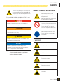 7
7
-
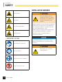 8
8
-
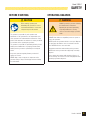 9
9
-
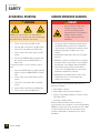 10
10
-
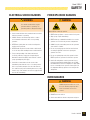 11
11
-
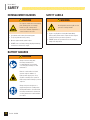 12
12
-
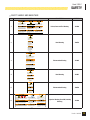 13
13
-
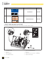 14
14
-
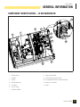 15
15
-
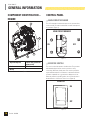 16
16
-
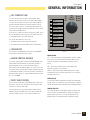 17
17
-
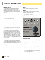 18
18
-
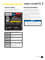 19
19
-
 20
20
-
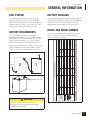 21
21
-
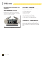 22
22
-
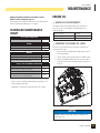 23
23
-
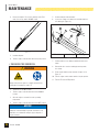 24
24
-
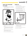 25
25
-
 26
26
-
 27
27
-
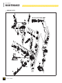 28
28
-
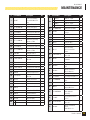 29
29
-
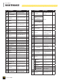 30
30
-
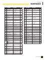 31
31
-
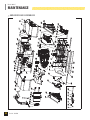 32
32
-
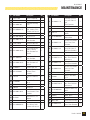 33
33
-
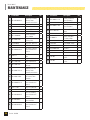 34
34
-
 35
35
-
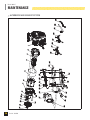 36
36
-
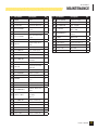 37
37
-
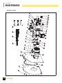 38
38
-
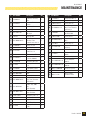 39
39
-
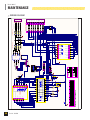 40
40
-
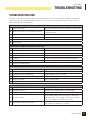 41
41
-
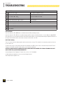 42
42
-
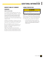 43
43
-
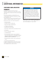 44
44
-
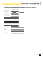 45
45
-
 46
46
-
 47
47
-
 48
48
-
 49
49
-
 50
50
-
 51
51
-
 52
52
-
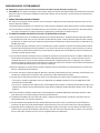 53
53
-
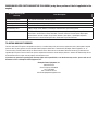 54
54


Champion Power Equipment 100237 Manual de usuario
- Categoría
- Generadores de poder
- Tipo
- Manual de usuario
- Este manual también es adecuado para
en otros idiomas
Artículos relacionados
-
Champion Power Equipment 100237 Manual del operador
-
 Champion Power Equipment 100179 El manual del propietario
-
 Champion Power Equipment Champion 12.5 Kilowatt Home Standby El manual del propietario
-
Champion Power Equipment Model #100510 Manual de usuario
-
Champion Power Equipment Model #100174 Manual de usuario
-
-
-
-
-
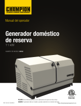 Champion Power Equipment 100152 Manual del operador


Otros documentos
-
 Lifan Power USA Platinum Series 15Kw Generator El manual del propietario
-
Eurotherm ATS48 Manual de usuario
-
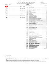 WTA 5500 Ficha de datos
-
Generac 20 kW G0059241 Manual de usuario
-
Simplicity 076150-01 Guía de instalación
-
Generac Power Systems 17 kW LP Installation Manuallines
-
CAT 530-1231 Instrucciones de operación
-
Danfoss Hot water circulation kit Guía de instalación

