LG DLEY1701VE El manual del propietario
- Categoría
- Secadoras
- Tipo
- El manual del propietario
Este manual también es adecuado para

Life's Good
DRYER
Please read this owner's manual fhoroucjhly before operating and keep it
handy for reference at ai[ limes.
DLEY1701*E DLGY1702*E
MFL67731021
wwwAg.com

2 TABLE OF CONTENTS
TABLE OF CONTENTS
3 iMPORTANT SAFETY iNSTRUCTiONS
3 WHAT TO DO IF YOU SMELL GAS
4 BASIC SAFETY PRECAUTIONS
4 CALIFORNIA SAFE DRINKING WATER AND
TOXIC ENFORCEMENT ACT
B GROUNDING INSTRUCTIONS
B SAFETY INSTRUCTIONS FOR
INSTALLATION
7 SAFETY INSTRUCTIONS FOR CONNECTING
ELECTRICITY
8 PRODUCT FEATURES
9 INTRODUCING YOUR DRYER
3S HOW TO USE
3B Operating the Dryer
36 Sorting Loads
36 Loading the Dryer
36 Check ihe Linl Filter Before Every Load
37 Using ihe LG EasyLoad M
38 Cycle Guide
39 Cycle Settings and Options
39 Special Functions
4-0 Custom Program
4-0 Steam Functions
4-1 ]ag On
4-2 Using ]ag On with Applications
9 Parts and Accessories
9 2--Way Reversible Door
10 Control Panel Features
11 Display
12 INSTALLATION INSTRUCTIONS
12 Preview Installation Order
13 Installation Location Requirements
13 Clearances
14- Leveling the Dryer
15 Reversing the Door
21 Installing the Side Vent Kit
22 Venting the Dryer
24- Connecting inlet Hose
25 Connecting Gas Dryers
27 Connecting Electric Dryers
32 Special Requirements for Manufactured or
Mobile Homes
32 Final Installation Check
33 Installation -rest (Duct Check)
48 MAINTENANCE
4-8 Regular Cleaning
49 TROUBLESHOOTING
4-9 Before Calling for Service
51 SPECIFICATIONS
52 USING SMART DIAGNOSIS TM
.53 WARRANTY

IMPORTANTSAFETYINSTRUCTIONS3
IMPORTANT SAFETY INSTRUCTIONS
READ ALL INSTRUCTIONS BEFORE USE
_WARNING
For your safety, the information in this manual must be followed to minimize the risk of fire or explosion, electric
shock, or to prevent property damage, injury to persons, or death.
f
Your safety and the safety of others is very important,
We have provided many important safety messages in this manual and on your appliance, Always read and obey a
safety messages.
This is the safety alert symbol,
This symbol alerts you to potential hazards that can kill or hurt you and others.
All safety messages will follow the safety alert symbol and either the word DANGER, WARNING, or CAUTION,
These words mean:
_DANGER
You will be killed or seriously injured if you don't immediately follow instructions,
_WARNING
You can be killed or seriously injured if you don't follow instructions,
A_CAUTION
You may be slightly injured or cause damage to the product if you do not follow instructions,
All safety messages will tell you what the potential hazard is,tell you how to reduce the chance of injury, and tell
you what can happen if the instructions are not followed,
• Do not install a clothes dryer with flexible plastic venting materials. If flexible metal (foil type) duct is
installed, it must be of a specific type identified by the appliance manufacturer as suitable for use with
clothes dryers. Flexible venting materials are known to collapse, be easily crushed, and trap lint. These
conditions will obstruct clothes dryer airflow and increase the risk of fire,
• Do not store or use gasoline or other flammable vapors and liquids in the vicinity of this appliance or any
other appliances.
• Installation and service must be performed by a qualified installer, service agency, or the gas supplier.
• Install the clothes dryer according to the manufacturer's instructions and local codes.
• Save these instructions,
WHAT TO DO IF YOU SMELL GAS:
1. Do not tryto light a match or cigarette, or turn on any gas or electrical appliance.
2, Do not touch any electrical switches. Do not use any phone in your building.
3. Clear the room, building, or area of all occupants.
4. Immediately call your gas supplier from a neighbor's phone. Follow the gas supplier's instructions
carefully.
5. If you cannot reach your gas supplier, call the fire department.
_WARNING:This product contains chemicals known to the State of California to cause cancer and birth defects or
other reproductive harm. Wash hands after handlin 9,

4 IMPORTANT SAFETY INSTRUCTIONS
IMPORTANT SAFETY INSTRUCTIONS
READ ALL INSTRUCTIONS BEFORE USE
_WARNING
For your safety, the information in this manual must be followed to minimize the risk of fire or explosion, electric
shock, or to prevent property damage, injury to persons, or death,
BASIC SAFETY PRECAUTIONS
_WARNING
To reduce the risk of fire, electric shock, or injury to persons when using this appliance, follow basic precautions,
including the following:
• Read all instructions before using the dryer.
• Before use, the dryer must be properly installed as
described in this manual.
• Do not place items exposed to cooking oils in your
dryer. Items contaminated with cooking oils may
contribute to a chemical reaction that could cause a
load to catch fire.
• Do not dry articles that have been previously cleaned
in, washed in, soaked in, or spotted with gasoline, dry-
cleaning solvents, or other flammable or explosive
substances as they give off vapors that could ignite or
explode.
• Do not reach into the dryer if the drum or any other
part is moving.
• Do not repair or replace any part of the dryer
or attempt any servicing unless specifically
recommended in this owner's manual or in published
user-repair instructions that you understand and have
the skills to carry out.
• Do not tamper with controls.
• Before the dryer is removed from service or discarded,
remove the door to the drying compartment.
• Do not allow children to play on or in the dryer. Close
supervision of children is necessary when the dryer is
used near children.
, Do not use fabric softeners or products to eliminate
static unless recommended by the manufacturer of
the fabric softener or product.
, Do not use heat to dry articles containing foam rubber
or similarly textured rubber-like materials.
, Keep area around the exhaust opening and adjacent
surrounding areas free from the accumulation of lint,
dust, and dirt.
, The interior of the dryer and exhaust vent should be
cleaned periodically by qualified service personnel.
, Do not install or store the dryer where it will be
exposed to the weather.
, Always check the inside of the dryer for foreign
objects.
, Clean lint screen before or after each load.
. Do not store plastic, paper, or clothing that may
burn or melt on top of the dryer during operation.
, Be careful when opening and closing the door.Fingers
and hands can get caught in the door and cause injury
if the door drops forward unexpectedly.
. Do not place heavy items on or lean against the top
of the door when it is open.
. Do not attempt to pull the hamper door open more
than 40 degrees.
, Tile dryer could tip forward, causing injury or damage.
, Do not place items on the top of the dryer.
CALiFORNiA SAFE DRiNKiNG WATER AND TOXIC ENFORCEMENT ACT
This act requires the governor of California to publish a list of substances known to the state to cause cancer, birth
defects, or other reproductive harm and requires businesses to warn customers of potential exposure to such
substances.
Gas appliances can cause minor exposure to four of these substances, namely benzene, carbon monoxide,
formaldehyde, and soot, caused primarily by the incomplete combustion of natural gas or LP fuels.
Properly adjusted dryers will minimize incomplete combustion. Exposure to these substances can be minimized
further by properly venting the dryer to the outdoors.

IMPORTANT SAFETY INSTRUCTIONS 5
IMPORTANT SAFETY INSTRUCTIONS
READ ALL INSTRUCTIONS BEFORE USE
_WARNING
For your safety, the information in this manual must be followed to minimize the risk of fire or explosion, electric
shock, or to prevent property damage, injury to persons, or death,
GROUNDING INSTRUCTIONS
This appliance must be grounded. In the event of
malfunction or breakdown, grounding will reduce
the risk of electric shock by providing a path of least
resistance for electric current. This appliance must be
equipped with a cord having an equipment-grounding
conductor and a grounding plug. The plug must be
plugged into an appropriate outlet that is properly
installed and grounded in accordance with all local
codes and ordinances.
_WARNING
Do not modify the plug provided with the appliance. If
it will not fit the outlet, have a proper outlet installed by
a qualified electrician.
This appliance must be connected to a grounded metal,
)ermanent wiring system or an equipment-grounding
conductor must be run with the circuit conductors and
connected to the equipment-grounding terminal or
lead on the appliance.
Electric shock can result if the dryer is not properly
grounded.
Improper connection of the equipment-grounding conductor can result in a risk of electric shock. Check with a
qualified electrician or service person if you are in doubt that the appliance is properly grounded.
SAFETY iNSTRUCTiONS FOR iNSTALLATiON
_WARNING
To reduce the risk of fire, electric shock, or injury to persons when using this appliance, follow basic precautions,
including the following:
• Properly ground dryer to conform with all
governing codes and ordinances. Follow details in
the installation instructions. Electric shock can result if
the dryer is not properly grounded.
• Before use, the dryer must be properly installed as
described in this manual. Electric shock can result if
the dryer is not properly grounded.
• InstaJl and store the dryer where it wiff not be
exposed to temperatures below freezing or
exposed to the weather.
• All repairs and servicing must be performed
by an authorized servicer unless specifically
recommended in this owner's manual. Use only
authorized factory parts. Failure to follow this
warning can cause serious injury, fire, electric shock, or
death.
• To reduce the risk of electric shock, do not install
the dryer in humid spaces. Failure to follow this
warning can cause serious injury, fire, electric shock, or
death.
Remove all packing items and dispose of all
shipping materials properly. Failure to do so can
result in death, explosion, fire, or burns.
Place dryer at least 18 inches above the floor for
a garage instaffation. Failure to do so can result in
death, explosion, fire, or burns.
Keep all packaging from children. Packaging
material can be dangerous for children. There is a risk
of suffocation.
Do not install near another source of heat such as
a stove, cooking oven. Failure to do so can cause
deform, smoke and fire.
Do not place candles, smoking materials, or other
flammables on top of the product. Dripping wax,
smoke, or fire can result.
Remove all protective vinyl film from the product.
Failure to do so can cause product damage, smoke or
fi re.
• Connect to a properly rated, protected, and sized
power circuit to avoid electrical overload. Improper
power circuit can melt, creating electric shock and/or
fire hazard.

6 IMPORTANTSAFETYINSTRUCTIONS
IMPORTANT SAFETY INSTRUCTIONS
READ ALL INSTRUCTIONS BEFORE USE
_WARNING
For your safety, the information in this manual must be followed to minimize the risk of fire or explosion, electric
shock, or to prevent property damage, injury to persons, or death,
SAFETY iNSTRUCTiONS FOR iNSTALLATiON
_WARNING
To reduce the risk of injury to persons, follow all industry recommended safety procedures including the use of long
sleeved gloves and safety glasses. Failure to follow all of the safety warnings in this manual could result in property
damage, injury to persons, or death.
Exhaust/Ducting:
• Gas dryers MUST be exhausted to the outside.
Failure to follow these instructions can result in fire or
death.
• The dryer exhaust system must be exhausted
to the outside of the dwelling. If the dryer is not
exhausted outdoors, some fine lint and large
amounts of moisture wii] be expelled into the
laundry area. An accumulation of lint in any area of
the home can create a health and fire hazard.
• Use only rigid metal or flexible metal 4-inch
diameter ductwork inside the dryer cabinet or for
exhausting to the outside. Use of plastic or other
combustible ductwork can cause a fire. Punctured
ductwork can cause a fire if it collapses or becomes
otherwise restricted in use or during installation.
• Ouctwork is not provided with the dryer, and you
should obtain the necessary ductwork locally. The
end cap should have hinged dampers to prevent
backdraft when the dryer is not in use. Failure to
follow these instructions can result in fire or death.
. The exhaust duct must be 4 inches (10.2 cm) in
diameter with no obstructions. The exhaust duct
should be kept as short as possible. Make sure
to dean any old ducts before installing your new
dryer. Failure to follow these instructions can result in
fire or death.
. Rigid or semi-rigid metal ducting is recommended
for use between the dryer and the wail in special
installations when it is impossible to make a
connection with the above recommendations, a UL-
listed flexible metal transition duct may be used
between the dryer and wall connection only. The
use of this ducting will affect drying time. Failure to
follow these instructions can result in fire or death.
. DO NOT use sheet metal screws or other fasteners
which extend into the duct that could catch lint and
reduce the efficiency of the exhaust system. Secu re
all joints with duct tape. For complete details, follow
the Installation Instructions. Failure to follow these
instructions can result in fire or death.

IMPORTANT SAFETY INSTRUCTIONS 7
IMPORTANT SAFETY INSTRUCTIONS
READ ALL INSTRUCTIONS BEFORE USE
_WARNING
For your safety, the information in this manual must be followed to minimize the risk of fire or explosion, electric
shock, or to prevent property damage, injury to persons, or death,
SAFETY iNSTRUCTiONS FOR CONNECTING ELECTRiCiTY
_WARNING
To reduce the risk of fire, electric shock, or injury to persons when using this appliance, follow basic precautions,
including the following:
. Do not, under any circumstances, cut or remove
the ground prong from the power cord. To prevent
injury to persons or damage to the dryer, the electrical
power cord must be plugged into a properly grounded
outlet.
. For personal safety, this dryer must be properly
grounded. Failure to do so can result in electric shock
or injury.
. Refer to the installation instructions in this manual
for specific electrical requirements for your model.
Failure to follow these instructions can create an
electric shock hazard and/or a fire hazard.
. This dryer must be plugged into a properly
grounded outlet. Electric shock can result if the
dryer is not properly grounded. Have the wall
outlet and circuit checked by a qualified electrician
to make sure the outlet is properly grounded.
Failure to follow these instructions can create an
electric shock hazard and/or a fire hazard.
. The dryer should always be plugged into its own
individual electrical outlet which has a voltage
rating that matches the rating plate. This provides
sparkling performance and also prevents overloading
house wiring circuits which could cause a fire hazard
from overheated wires.
. Never unplug your dryer by pulling on the power
cord. Always grip plug firmly and pull straight out
from the outlet. The power cord can be damaged,
resulting in a risk of fire and electric shock.
. Repair or replace immediately all power cords that
have become frayed or otherwise damaged. Do not
use a cord that shows cracks or abrasion damage
along its length or at either end. The power cord can
melt, creating an electric shock and/or fire hazard.
. When installing or moving the dryer, be careful not
to pinch, crush, or damage the power cord. This will
prevent injury and prevent damage to the dryer from
fire and electric shock.
SAVE THESE INSTRUCTIONS

8 PRODUCT FEAiTURES
PRODUCT FEATURES
An entire selection of user-friendly functions make operating the dryer easy.
The LG EasyLoad TM can be tilted open from the top, hamper-style, allowing you to easily load the dryer without
items falling on the floor. The door still swings open to provide easy access for unloading or loading of bulkier
items. The door hinge can be reversed to adjust for installation location.
LG'ssteam technology allows you to inject fabrics with a swirling jet of steam to refresh clothes, reduce static, and
make ironing easier. Simply select the Steam FreshTM cycle or Wrinkle Care cycle.
The Flow Sense TM duct blockage sensing system detects and alerts you to restrictions in the installed household
ductwork that reduce exhaust airflow through the dryer. If you see the alert: Clean or repair the ducts to remove
the restrictions. Keep your ducts clean to help increase efficiency and reduce long drying times caused by blocked
ducts.
Should you experience any technical difficulty with your dryer, it has the capability of transmitting data via your
telephone to the Customer Information Center. The call center agent records the data transmitted from your
machine and uses it to analyze the issue, providing a fast and effective diagnosis.
The Tag On feature works on most smart phones equipped with the NFC function and based on the Android
operating system (OS).
Using the "LG Smart Laundry" application, the Tag On feature will allow you to diagnose your appliance, download
new cycles, and see the status of your appliance by simply touching the smartphone to the Tag On logo of the
appliance.
_S_ Protocol P154
Sanitization Performance of
Residential Clothes dryer

INTRODUCING YOUR DRYER 9
INTRODUCING YOUR DRYER
Parts and Accessories
Parts
Control
panel
Reversible
door
Terminal -
block
access panel
(Electric
models)
Gas -
Lint filter connection
Leveling ....................................... location Exhaust
feet (Gas models) duct
outlet
location
(Gas
models)
Water inlet
valve
Accessories
2-Way Reversible Door
Y connector
Drying rack
Hose
Optionalaccessories
Side vent kit
(sold separately)
Kit No. 383EEL9001B
Swing door
The LG EasyLoad TM feature allows you to open the dryer
door from the top, hamper-style, when loading the
dryer to help guide clothes into the drum and prevent
them from falling onto the floor. When unloading the
dryer or loading bulkier items, use the swing door for
easy access to the drum. For more details on using the
door, see page 37. For information on reversing the
door swing, see page 15.
@ NOTE
Contact LG Customer Service at 1-800-243-0000 (1-888-542-2623 in Canada) if any accessories are missing.
For your safety and for extended product life, use only authorized components. The manufacturer is not
responsible for product malfunction or accidents caused by the use of separately purchased unauthorized
components or parts.
The images in this owner's manual may be different from the actual components and accessories, and are
subject to change by the manufacturer without prior notice for product improvement purposes.

10 INTRODUCINGYOURDRYER
Confrol Panel F'eafures
Following are instructions for starting and using your new dryer. Please refer to specific sections of this manual for
more detailed information.
_WARNING
To reduce the risk of fire, electric shock, or injury to persons, read this entire manual, including the Important Safety
Instructions, before operating this dryer.
i
Q POWER ON/OFF BUTTON
Press to turn the dryer ON. Press again to turn
the dryer OFF.
o@NOTE
ressing the ON/OFF button during a cycle will
ncel that cycle and any load settings will be lost.
k
0 CYCLEBUTTONS
Press the Cycle button repeatedly to scroll
through the cycle selections until the desired
cycle is selected. The standard presets for the
selected cycle will be shown in the display.
On MANUAL DRY cycles, these settings can be
adjusted using the cycle setting buttons anytime
before starting the cycle.
START/PAUSEBUTTON
Press this button to start tile selected cycle. If
the dryer is running, use this button to pause
the cycle without losing the current settings.
F__NOTE
I If you do not press the START/PAUSEbutton to
I resume a cycle within 4 minutes, the dryer turns
_off automatically.
®
O
®
@
MORE TIME/LESSTiME BUTTONS
Use these buttons with tile Time Dry and other
MANUAL DRY cycles to adjust the drying time.
Press the More Time button to increase the
selected manual cycle time by one minute;
press Less Time to decrease the cycle time by
one minute,
CYCLESETTING BUTTONS
Use these buttons to select the desired cycle
settings for the selected cycle. The current
settings are shown in the display. Press the
button for that option to select other settings.
TIME AND STATUSDISPLAY
The display shows the settings, estimated time
remaining, options, and status messages for
your dryer.
OPTION BUTTONS
The option buttons allow you to select
additional cycle options. Certain buttons also
allow you to activate special functions by
pressing and holding the button for 3 seconds.
STEAM FUNCTIONS
LG's steam technology allows you to inject
fabrics with a swirling jet of steam to refresh
clothes, reduce static, and make ironing
easier. Simply select the Steam FreshTM cycle or
Wrinkle Free cycle.

INTRODUCINGYOURDRYER]]
Display
Following are instructions for starting and using your new dryer. Please refer to specific sections of this manual for
more detailed information.
_WARNING
To reduce the risk of fire, electric shock, or injury to persons, read this entire manual, including the Important Safety
Instructions, before operating this dryer.
ESTIMATED TIME REMAINING
This display shows the estimated time remaining
for SENSOR DRY cycles or the actual time
remaining for Time Dry or MANUAL DRY cycles.
f-_NOTE
IThe cycle time on SENSORDRYcycles may
fluctuate as the dryer recalculates drying time for
optima resu ts.
CLEAN FILTERREMINDER
The display will show Clean Filter when the
dryer is turned on as a reminder to check the
filter. It turns off when the START/PAUSE button
is pressed.
CYCLECOMPLETION INDICATOR
WITH CHECK FILTERREMINDER
This portion of the display shows which stage
of the drying cycle is currently underway (Clean
Filter, Drying, Cooling).
CUSTOM PROGRAM
If you have a special combination of settings
that you use frequently, you can save these
settings as a Custom Program.
CHILD LOCK INDICATOR
When Child Lock is set, the Child Lock indicator
will appear and all buttons are disabled except
the POWERbutton. This prevents children from
changing settings while the dryer is operating.
Flow Sense TM DUCT BLOCKAGE
SENSING SYSTEM INDICATOR
The Flow SenseTM duct blockage sensing
system detects and alerts you to blockages in
the ductwork that reduce exhaust flow from
the dryer. Maintaining a clean exhaust system
improves operating efficiency and helps
minimize service calls, saving your money.

12 INSTALLAiTIONINSTRUCTIONS
INSTALLATION INSTRUCTIONS
Preview Installation Order
Checking and
choosing the proper
location
Li- :::"'J
Leveling the dryer Venting the dryer
Connecting the inlet hose Connecting gas
dryers
Connecting electric
d rye rs
240V
Plugging in the
power cord and
grounding
Press and hold
installation test
(Refer to page 33,)
Test run

INSTALLATION INSTRUCTIONS 13
Insfallafion Locafion Requiremenfs
_WARNING
Read all installation instructions completely before installing and operating your dryer! It is important that
you review this entire manual before installing and using your dryer. Detailed instructions concerning electrical
connections, gas connections, and exhaust requirements are provided on the following pages.
• A location that allows for proper exhaust installation. A
gas dryer must be exhausted to the outdoors.
See Venting the dryer,
• A grounded electrical outlet located within 2 ft.
(61 cm) of either side of the dryer. See Connecting
electric dryers,
. A sturdy floor to support the total dryer weight of 200
Ibs (90.7 kg). The combined weight of a companion
appliance should also be considered.
. No other fuel-burning appliance can be installed in the
same closet as a dryer.
Do not operate your dryer at temperatures below 45°F (7°C). At lower temperatures, the dryer might not shut off
at the end of an automatic cycle. This can result in longer drying times. The dryer must not be installed or stored in
an area where it will be exposed to water and/or weather. Check code requirements. Some codes limit, or do not
permit, installation of the dryer in garages, closets, mobile homes or sleeping quarters. Contact your local building
inspector.
'10 NOTE
level floor with a maximum slope of 1 inch (2.5 cm) under entire dryer. If slope is greater than 1 inch (2.5 cm),
install the Extended Dryer Feet Kit, Clothes may not tumble properly, and automatic sensor cycles may not
perate correctly if dryer is not level.
or a garage installation, you will need to place the dryer at least 18 inches (46 cm) above the flooL If using a
pedestal, you will need 18 inches (46 cm) to the bottom of the dryer.
Clearances
_,,
(2.54 Crfl) (686 on1) (2.54 ore)
(760m)
Closet Door Vent
(7 6 era) Requirement5
INSTALLATION SPACING FOR RECESSEDAREA OR CLOSET INSTALLATION
The following spacing dimensions are recommended for this dryer. This dryer has been tested for spacing of
1 inch clearance on the sides and rear. Recommended spacing should be considered for the following reasons:
• Additional spacing should be considered for ease of
installation and servicing,
• Additional clearances might be required for wall, door
and floor moldings.
• Additional spacing should be considered on all sides
of the dryer to reduce noise transfer.
For closet installation, with a door, minimum
ventilation openings in the top and bottom of the
door are required. Louvered doors with equivalent
ventilation openings are acceptable.
• Companion appliance spacing should also be
considered.
O NOTE
here should be at least a little space around the dryer (or any other appliance) to eliminate the transfer of
ibration from one to the other. Too much vibration, it could cause them to make noise or touch each other
using paint damage and making even more noise.

14 INSTALLATION INSTRUCTIONS
Clearances (cont.)
RECOMMENDED INSTALLATION SPACING FOR CABINET INSTALLATION
• For cabinet installation with a door, minimum ventilation openings in the top of the cabinet are required,
*Required spacing
**For side or bottom venting,
2 inches (5,1 cm) spacing is allowed.
m
T
5"* 281s/_" 1"* 1'_11_27 ''_1_1''
12.7cm (73.4cm) 2.8cm (2.84cm) (68.6cm) (2.84cm)
Leveling fhe Dryer
_WARNING
• To reduce the risk of injury to persons, adhere to all
industry recommended safety procedures including
the use of long sleeved gloves and safety glasses.
Failure to follow this warning can cause serious injury
or death.
•The appliances are heavy, Two or more people are
required when installing the dryer. Failure to follow
this warning can cause serious injury or death.
To ensure that the dryer provides optimal drying
performance, it must be level. To minimize vibration,
noise, and unwanted movement, the floor must be a
perfectly level, solid surface.
..-@NOTE ---,
Adjust the leveling feet only as far as necessary to
level the dryer. Extending the leveling feet more than K
1.Position the dryer in the final location. Place a level
across the top of the dryer.
. All four leveling feet must rest solidly on the floor.
Gently push on the top corners of the dryer to make
sure that the dryer does not rock from corner to corner.
If you are installing the dryer on the optional pedestal,
you must use the leveling feet on the pedestal to
level the dryer. The dryer leveling feet should be fully
retracted.
2. Use an adjustable wrench to turn the leveling feet.
Turn clockwise to raise the dryer or counterclockwise
to lower it. Raise or lower the leveling feet until dryer
is level from side to side and front to back.
Make sure that all 4 leveling feet are in firm contact with
the floor.
Leveling Feet

INSTALLAiTIONINSTRUCTIONS15
Reversing the Door
Before you begin
7 @ NOTE -.
The door reversal procedure for the two-way door
_is far more complex than for a conventional dryer
/ door. It is recommended that you read through these
instructions in their entirety before beginning the
/ process, in order to gauge whether you prefer to have I
/ the procedure done by a professional installer or
The door reversal procedure consists of four main parts:
. Removing and reinstalling the door and hinges (steps
1, 2 and 20)
. Removing and reversing components on the dryer
cabinet (step 3)
. Removing and reversing components on the door
cover (steps 4 and 5)
. Removing and reversing components inside the door
(steps 6 through 1g).
Tools Required
• Phillips screwdriver
• Large flat blade screwdriver (recommended for hinge
screws if they are tight or your Phillips screwdriver is
worn)
• Small flat blade screwdriver (for lifting out parts)
&WARNING
• To avoid damage to the dryer or the door, support
the door with a stool or box that fits under the door,
or have an assistant support the weight of the door.
• Avoid dropping the door to avoid damage to the
door or the floor.
• Unplug the dryer or turn off power at the main
circuit breaker before beginning door reversal.
• THE DRYER DOOR ISVERY LARGE AND HEAVY.
Failure to follow the instructions below can result in
damage to the dryer, property damage or personal
injury.
Instructions
@NOTE -_
he instructions here are for changing the door swing_
om a right to a left side hinge. If the door has been
versed, and it is necessary to change it back, use
re when following these instructions. Some of
e illustrations and the left/right references will be
versed, and you will need to read the instructions
/
_WARNING
Be sure to support the weight of the door before
removing the hinge screws,
1. Open the door from the side so that the hinge
screws are accessible.
Two large
screws
Two small
screws
2. Remove the four hinge screws.
While supporting the door, remove the four hinge
screws, two from each hinge. Set the door aside face
down on a protected surface to prevent damage to
the door or the work surface.
3. Reverse the components on the cabinet.
a. Use a Phillips screwdriver to remove the two screws
and the latch mechanism on the front panel of the
cabinet.
hinge
cover =
latch
mechanism"
hinge.
upper
hinge
latch hole
cover
hinge
bracket
b. Remove the latch hole cover by gently prying it
up with a flat blade screwdriver, being careful not
to scratch the paint. Install the latch hole cover on
the opposite side, where the latch mechanism was
removed. Install the latch mechanism in the position
from which you removed the latch hole cover, using
the two screws removed in step a.
c. Remove the hinge cover by gently prying it up with
a flat blade screwdriver, being careful not to scratch
the paint. Rotate the hinge cover 180 degrees and
install it on the opposite side, where the upper hinge
was attached.

16 INSTALLAiTIONINSTRUCTIONS
Reversing the Door (continued)
hinge
cover"
latch
mechanism"
hinge.
upper
"hinge
latch hole
•cover
hinge
°bracket
d. Reverse the hinge and the hinge bracket at the
bottom of the ca binet. Remove the two screws from
the hinge bracket at bottom right and remove the
hinge bracket.
Remove the lower of the two
screws behind the hinge
bracket. Do NOT remove the
upper screw behind the hinge
bracket. Set the parts aside.
- __ NOTE ..N
Do NOT remove any of the eight screws on the face of
the cabinet (marked with (_,! below). Doing so could
result in damage to the dryer and the need for a
service call to repair the dryen
e. Remove the three screws on the
hinge at bottom left. Remove the
hinge and reinstall it on the right
side. The top screw occupies the
hole where you removed the screw
behind the hinge bracket in step d.
f. Install the hinge bracket removed in step d on the
bottom left side, first installing one screw behind the
hinge bracket.
ON THE DOOR:
4. Lift off the door cover.
With the door laid inside facing up on a protected
surface, remove the 12 screws on the inside of the
door. Carefully lift offthe door cover with the help of
a small flat blade screwdriver inserted in the upper
corner (circled below).
_WARNING
The edges of the door cover may be sharp.Take care
when handling, or wear gloves to avoid injury.
......... twelve screws ........
S. Switch the door strike and the blank cover.
Remove the four screws on the door cover that secure
the door strike and the blank cover.
Switch the door strike and the blank cover, installing
them on the opposite sides from which they were
removed.
long screw
short
blank cover door strike
Gently pry out the hole plug on the side of the door
cover and install it in the hole on the opposite side.
hole plug
Set the door cover aside.

INSTALLAiTION INSTRUCTIONS 17
Reversing the Door (continued)
6. Reverse the components inside the door.
You will now be removing and reversing various components inside the door. See below for a detailed diagram
and identification of the inner structure and parts of the door. (The diagram shows the "before view" of the door,
with the default set-up for a right side hinge swing. After following these instructions, your door should be a
mirror image of the illustration.)
Inner Structure of Door
(before reversing - right hinge swing)
upper hinge
assembly
Top interlock buttons
inner lock rods
upper hinge
filler
glass
lower hinge
filler
lower lower
hinge hinge
assembly bracket
bumpers
interlock buttons lower hinge filler side lock rod
lUmm_r-,
inner lock rods lower hinge bracket Hole plug
top lock rod
lower hinge assembly

18 INSTALLAiTIONINSTRUCTIONS
Reversing fhe Door (confinued)
7. Lift out the two top interlock buttons,
Lift out the two grey interlock buttons from the top of
the outer door and set them aside for later use.
8. Lift out the grey interlock button in the side of the
door,
Make sure to remove tile spring with the interlock
button and to keep the two together. Set the interlock
button aside, Do not confuse with interlock buttons
from the top of the outer door.
g. Remove the side lock rod. H 1_._ _
Remove the side lock rod from
the lower hinge bracket by lifting
the top end of the rod and sliding
it toward the top of the door. The
spring should remain attached to
the lock rod, Set the lock rod aside, ,_ [_-_
Spring
10, Remove the top lock rod.
a. Slide the lock rod to the right to remove it from the
hinge assembly on the left side.
b.While sliding the lock rod right, lift the right end up
and out of the guides.
@ NOTE i/
o not remove the two inner lock rods (see page 17)
cated underneath the top lock rod, They do NOT
eed to be reversed
11. Remove the upper hinge pivot,
Once the top lock rod has been removed, the
hinge pivot can easily be removed from the hinge
assembly on the upper left and set aside,
upper hinge
assembly
upper hinge
pivot
L
Z
12. Reverse the upper hinge assembly and hinge
filler.
Lift out tile upper hinge filler (on the right) and set it
aside.
Carefully lift the upper hinge assembly (on the left)
out of the outer door frame, using a small flat blade
screwdriver if necessary. Rotate the hinge assembly
180 degrees and install it on the upper right side of
the outer door, You will need to press firmly to install
the hinge assembly.
The hinge pivot removed in step 11 will be installed
later.
upper hinge assembly
upper hinge pivot

INSTALLATIONINSTRUCTIONS1_
Reversing the Door (continued)
Now rotate the hinge filler 180 degrees and install it
on the upper left side of the door.
f
_( upper hinge filler
13. Reinstall the top lock rod.
Rotate the top lock rod (removed in step 10) 180
degrees end for end from its original position and
reinstall it. The spring should now be to the right of
center, with the spring on the side of the rod facing
the top of the door.
a. Insert the right end of the lock rod into the right
hinge assembly. Make sure the rod is aligned with
the guides in the door panel.
b. Lower the rod into position, sliding it to bypass the
center handle, making sure to align the lock rod
with the guides all the way across the door panel.
When released, the lock rod should slide completely
into the hinge assembly on the right. Slide the
lock rod back and forth to make sure it is correctly
positioned in the guides and slides easily.
b. Rotate the lower hinge assembly 180 degrees and
install it on the right side using the two screws
removed in step a. screws
lower hinge assembly _" b
c. Flip over the lower hinge bracket and release the
tabs on the back locking the hinge filler to the hinge
bracket.
d, Rotate the hinge filler 180 degrees and snap it back
onto the FRONT of the hinge bracket facing in the
opposite_ 7 j----_direction,
e, Mount the lower hinge bracket and the filler on the
left side of the door with the screw removed in step a.
e
14. Reverse the lower hinge bracket and hinge
assembly.
a. Remove the screw from the lower hinge bracket (on
the right) and lift the hinge bracket out. Set it aside.
Remove the two screws from the lower hinge assembly
on the bottom left and lift the hinge assembly out.
15. Install the side lock rod.
Flip the side lock rod over and install it on the
opposite side. Insert the lower end into the left
hinge and lower the rod into the guides on the door
while compressing the spring inside the recess.
J

20 INSTA LLAiTION INSTRUCTIONS
Reversing fhe Door (confinued)
Make sure the top of the side lock rod is beside the top
lock rod and the two do not overlap each other, so the
two rods can interact correctly. If they are not aligned
properly, the door will not operate properly.
16. Reinstall the top interlock buttons.
Reinstall the top gray interlock buttons removed in
step 7, one on each side of the outer door panel.
17. Reinstall the side interlock button.
Reinstall the side interlock button removed in step 8.
Center the spring in the compartment and insert the
interlock button on top of it.
'4
18. Reinstall the door cover.
Clean the glass on the door and door cover, if
necessary.
Make sure the three gray interlock buttons are
properly installed and that the top and side lock
rods are properly aligned where they meet. Carefully
lower the door cover into place, aligning the holes in
the cover with the interlock buttons on the top and
side and the bumpers on the bottom. Take care not
to dislodge the lock rods while mounting the door
cover. Once the door cover is in place, secure it with
the 12 screws removed in step 4.
The ten similar screws go around the top and sides
of the door cover. Make sure to install the two
different screws on the bottom edge, in the locations
marked below
interlock
buttons
_ ///,bumpers
19. Now, pick up the upper hinge pivot removed earlier and
rotate it 180 degrees. Pressinthe side interlock button
on the left sideand hold it down while you pressthe hinge
pivot into the hinge assembly on the top right side. If the
door hasbeen reassembled correctly, the lock rod will slide
back easily and lock the pivot in place.The door isnow
ready to remount on the opposite side of the dryer.
A, WARNING
Besure to support the weight of the door before installing
the hinge screws.
20. Reinstall the door.
While supporting the door, install the four hinge screws
removed in step 2.Testthe swing ofthe door to make sure
the hinges and latch are properly aligned and that the
door opens, closes and latches properly in both directions.
Two large
screws
Two small
screws
Ifthe door doesn't operate smoothly, remove the door
and then the door cover to check that the lock rods and
interlock buttons are properly mounted and aligned.
The interlock buttons should be oriented correctly and
operating smoothly. The interlock rods should be in the
proper position and should not overlap atthe contact
point. (See steps 13-15.)
Ifthe door is damaged, or ifthe door does not work after
reassembly, contact the call center at 1-800-243-0000.

INSTALLAiTIONINSTRUCTIONS21
Insfalling fhe Side Venf Kif
_WARNING
Use a heavy metal vent.
Do not use plastic or thin foil duct.
• Clean old ducts before installing this dryer.
• To reduce the risk of injury to persons, adhere to all
industry recommended safety procedures including
the use of long sleeved gloves and safety glasses.
• Failure to follow all of tile safety warnings in this
manual could result in property damage, injury to
persons, or death.
Your new dryer is shipped to vent to the rear. It can also
be configured to vent to the bottom or side (right-side
venting is not available on gas models).
An adapter kit, part number 383EELgO01 B, may be
purchased from your LG retailer. This kit contains the
necessary duct components to change the dryer vent
location.
1.Remove the rear exhaust duct retaining screw. Pull
out the exhaust duct.
Retaining
Screw
3.Preassemble a 4 inches (10.2 cm) elbow to the next
4-inches (10.2 cm) duct section, and secure all joints
with duct tape. Be sure that the male end of the
elbow faces AWAY from the dryer. Insert the elbow/
duct assembly through the side opening and press it
onto the adapter duct. Secure in place with duct tape.
Be sure that the male end of the duct protrudes 12z4
inches (3.8 cm) to connect the remaining ductwork
Attach cover plate to the back of the dryer with
included screw.
Cover
Plate
OPTION 2: BOTTOM VENTING
2. Press the adapter duct onto the blower housing and
secure to the base of the dryer as shown.
Adapter
?
Bracket
OPTION 1: SIDE VENTING
2. Press the tabs on the knockout and carefully remove
the knockout for the desired vent opening (right-
side venting is not available on gas models). Press the
adapter duct onto the blower housing and secure to
the base of the dryer as shown.
Adapter
Duct .-'"
Bracket
3.Insert the 4 inches (10.2 cm) elbow through the rear
opening and press it onto the adapter duct. Be sure
that the male end of the elbow faces down through
hole in the bottom of the dryer. Secure in place with
duct tape. Attach the cover plate to the back of the
dryer with included screw.
Cover,
Plate

22 INSTA LLAiTION INSTRUCTIONS
Venfing fhe Dryer
_WARNING
To reduce the risk of fire, electric shock, or injury to persons when using this appliance, follow basic precautions,
including the following:
• Do not crush or collapse ductwork. Failure to follow
these instructions can result in fire or death.
• Do not allow ductwork to rest on or contact sharp
objects. Failure to follow these instructions can result
in fire or death.
• If connecting to existing ductwork, make sure it
is suitable and clean before installing the dryer.
Failure to follow these instructions can result in fire or
death.
• Venting must conform to local building codes.
Failure to follow these instructions can result in fire or
death.
• Gas dryers MUST exhaust to the outdoors. Failure to
follow these instructions can result in fire or death.
• Use only 4-inch (10.2 cm) rigid or flexible metal
ductwork inside the dryer cabinet and for venting
outside. Failure to follow these instructions can result
in fire or death.
• To reduce the risk of fire, combustion, or
accumulation of combustible gases, DO NOT
exhaust dryer air into an enclosed and unventilated
area, such as an attic, wall, ceiling, crawl space,
chimney, gas vent, or concealed space of a building.
Failure to follow these instructions can result in fire or
death.
• To reduce the risk of fire, DO NOT exhaust the dryer
with plastic or thin foil ducting. Failure to follow
these instructions can result in fire or death.
• The exhaust duct must be 4 inches (10.2 cm) in
diameter with no obstructions. The exhaust duct
should be kept as short as possible. Make sure
to clean any old ducts before installing your new
dryer. Failure to follow these instructions can result in
fire or death.
®Rigid or semirigid metal ducting isrecommended
for use between the dryer and the wall. in special
installations when it is impossible to make a
connection with the above recommendations, a UL-
listed flexible metal transition duct may be used
between the dryer and wall connection only. The
use of this ducting will affect drying time. Failure to
follow these instructions can result in fire or death.
®DO NOT use sheet metal screws or other fasteners
which extend into the duct that could catch lint
and reduce the effi ciency of the exhaust system.
Secure all joints with duct tape. Failure to follow
these instructions can result in fire or death.
®Ductwork is not provided with the dryer. You
should obtain the necessary ductwork locally. The
end cap should have hinged dampers to prevent
backdraft when the dryer is not in use. Failure to
follow these instructions can result in fire or death,
• The total length of flexible metal duct shall not
exceed 8 ft. (2.4m).
• in Canada, only those foil-type flexible ducts,
if any, specifically identified for use with the
appliance by the manufacturer shall be used. In tile
United States, only those foil-type flexible ducts, if any,
specifically identified for use with the appliance by the
manufacturer and that comply with the Outline for
Clothes Dryer Transition Duct, Subject 21S8A, shall be
used.

INSTALLAiTIONINSTRUCTIONS23
Venting the Dryer (conf.)
Ductwork
Recommended
(10.2 cm)
(10.2 crn)
Use only for
short run
installations
J
o
I
2
3
4
o
I
2
3
4
65 ft, (19,8 m)
55 ft. (16.8 m)
47 ft. (14,3 m)
36 ft. (11,0 m)
28 ft. (8.5 m)
55 ft. (16.8 m)
47 ft. (14.3 m )
41 ft. (12.5 m)
30 ft. (9,1 m)
22 ft, (6.7 m)
- _ NOTE -.,
Deduct 6 ft. (1.8 m) for each additional elbow. It is not
recommended to use more than four 90° elbows.
Routing and Connecting Ductwork
-+_ NOTE
Follow the guidelines below to maximize drying
performance and reduce lint buildup and
condensation in the ductwork,
Ductwork and fittings are NOT included and must be
purchased separately.
. Use 4-inch (10.2 cm) diameter rigid or semirigid
metal ductwork,
. The exhaust duct run should be as short as possible,
. Use as few elbow joints as possible,
. The male end of each section of exhaust duct must
point away from the dryer,
. Use duct tape on all duct joints,
. Insulate ductwork that runs through unheated areas
in order to reduce condensation and lint buildup on
duct surfaces.
. Incorrect or inadequate exhaust systems are not
covered by the dryer warranty. Failures or poor
performance caused by such exhaust systems will
not be covered by the dryer warranty.
CORRECT VENTING
INCORRECT VENTING
b

24 INSTALLATION INSTRUCTIONS
Connecfing Inlef Hose
The dryer must be connected to tile cold water tap using tile new water supply }lose. Do not use old hoses
lIDW@NOTE
ater supply pressure must be between 21.8 PSIand 116 PSI (150-800 kPa).
o not strip or cross-thread when connecting inlet hose to the valve.
If the water supply pressure is more than 800 kPa, a decompression device should be installed.
Periodically check the condition of the hose and replace the hose if necessary.
Replace inlet hoses after Syears of use to reduce the risk of hose failure.
• Record hose installation or replacement dates on the hoses for future reference.
1. Check rubber seal in the inlet hose. Two rubber seals
are supplied with each inlet hose. They are used for
preventing water leaks. Make sure the connection to
the cold water tap is tight.
I
Hose
seal
Y connector
2. Check the installation type.
3.Connect the hose to the dryer.
, Connect the water supply hose to the dryer inlet valve
tightly by hand and then tighten another 2/3 turn with
pliers.
Make sure that there are no kinks in the hoses and that
they are not crushed.
I
_--Short
lilly hose
Y connector
I
--Long""
hose
WITH WASHER WITHOUT WASHER
Connect all water supply hoses tightly by hand and
then tighten another 2/3 turn with pliers.
WITH WASHER: When connecting the dryer to the
same faucet as a washer.
a, Shut off the cold water tap and remove the washer hose.
b, Connect the short hose to the Y-connector using one
of the hose washers.
c, Connect the other end of the short hose to the cold
water faucet.
d. Connect the long dryer hose to one side of theY-connector
and connect the washer hoseto the other side.
WITHOUT WASHER: If the dryer does not share the
cold water tap with a washer.
a. Connect tile straight end of the long hose to the cold
water faucet.
S _ NOTE
I • Before connecting the water line to the dryer, flush
I several gallons of water into a drain or bucket.This will
I help prevent foreign particles such assand and scale
I from clogging the dryer inlet valve.
•Do not overtighten. Damage to the coupling can result.
4. Turn on the cold water faucet.
S. Check for leaks at the Y-connector (if used) and in all
hoses,
I
_NOTE
If any leaks are found, shut off the water faucet,
remove the hose and check the condition of the

INSTALLAiTIONINSTRUCTIONS25
Connecfing Gas Dryers
_WARNING
To reduce the risk of fire, electric shock, or injury to persons when using this appliance, follow basic precautions,
including the following:
• Gas supply requirements:
As shipped from the factory, this dryer is
configured for use with natural gas. It can be
converted for use with LP (Liquefied Propane) gas.
Gas pressure must not exceed 13 inches of water
¢o_ullrln.
• A qualified service or gas company technician must
connect the dryer to the gas service.
Failure to do so can result in fire, explosion, or death.
• Isolate the dryer from the gas supply system by
closing its individual manual shutoff valve during
any pressure testing of the gas supply. Failure to do
so can result in fire, explosion, or death.
• Supply line requirements:
Your laundry room must have a rigid gas
supply line to your dryer, in the United States,
an individual manual shutoff valve MUST be
installed within at least 6 ft. (1.8 m) of the dryer,
in accordance with the National Fuel Gas Code
ANSi Z223.1 or Canadian gas installation code CSA
B149.1. A 1/s- inch NPT pipe plug must be installed.
Failure to do so can result in fire, explosion, or death.
• if using a rigid pipe, the rigid pipe should be Y2
- inch IPS. If acceptable under local codes and
ordinances and when acceptable to your gas
supplier, _s- inch approved tubing may be used
where lengths are less than 20 ft. (6.1 m). Larger
tubing should be used for lengths in excess of 20 ft.
(6.1 m). Failure to do so can result in fire, explosion, or
death.
. Connect the dryer to the type of gas shown on
the nameplate. Failure to do so can result in fire,
explosion, or death.
. To prevent contamination of the gas valve,
purge the gas supply of air and sediment before
connecting the gas supply to the dryer. Before
tightening the connection between the gas supply
and the dryer, purge remaining air until the odor
of gas is detected. Failure to do so can result in fire,
explosion, or death.
. DO NOT use an open flame to inspect for gas leaks.
Use a noncorrosive leak-detection fluid. Failure to
do so can result in fire, explosion, or death.
. Use only a new AGA- or CSA-certiffed gas supply
line with flexible stainless steel connectors. Failure
to do so can result in fire, explosion, or death.
. Securely tighten all gas connections. Failure to do
so can result in fire, explosion, or death.
. DO NOT attempt any disassembly of the dryer;
any disassembly requires the attention and tools
of an authorized and qualified service person or
company. Failure to do so can result in fire, explosion,
or death.
. Use a pipe-joint compound that isinsoluble in
Liquefied Petroleum (LP) gas on all pipe threads.
Failure to do so can result in fire, explosion, or death.
Electrical requirements for gas models only
_WARNING
To reduce the risk of fire, electric shock, or injury to persons when using this appliance, follow basic precautions,
including the following:
• Do not, under any circumstances, cut or remove the . This dryer must be plugged into a 60 Nz, 120 VAC,
third (ground) prong from the power cord. Failure grounded outlet protected by a 1S-ampere fuse
to follow this warning can result in fire, explosion, or or circuit breaker. Failure to follow this warning can
death, result in fire, explosion, or death.
• For personal safety, this dryer must be properly
grounded. Failure to follow this warning can result in
fire, explosion, or death.
• The power cord of this dryer is equipped with
a 3-prong (grounding) plug which mates with
a standard 3-prong (grounding) wall outlet to
minimize the possibility of electric shock hazard
from this appliance. Failure to follow this warning
can result in fire, explosion, or death.
. Where a standard 2-prong wall outlet is
encountered, it is your personal responsibility
and obligation to have it replaced with a properly
grounded 3-prong wall outlet. Failure to follow this
warning can result in fire, explosion, or death.

26 INSTALLAiTIONINSTRUCTIONS
Connecting Gas Dryers (conf.)
_WARNiNG
To reduce the risk of fire, electric shock, or injury
to persons when using this appliance, follow basic
precautions, including the following:
• Installation and service must be performed by
a qualified installer, service agency, or the gas
supplier. Failure to do so can result in fire, explosion,
or death.
• Use only a new stainless steel flexible connector
and a new AGA-certified connector. Failure to do so
can result in fire, explosion, or death.
• A gas shutoff valve must be installed within 6 ft.
(1.8 m} of the dryer. Failure to do so can result in fire,
explosion, or death.
• The dryer isconfigured for Natural Gas when
shipped from the factory. Make sure that the dryer
is equipped with the correct burner orifice for the
type of gas being used (Natural Gas or Liquefied
Petroleum}. Failure to do so can result in fire,
explosion, or death.
• If necessary, the correct orifice (For the LP orifice
kit, order part number 383EEL3002D) should be
installed by a qualified technician and the change
should be noted on the dryer. Failure to do so can
result in fire, explosion, or death.
• All connections must be in accordance with local
codes and regulations. Failure to do so can result in
fire, explosion, or death.
• Gas dryers MUST exhaust to the outdoors. Failure to
do so can result in fire, explosion, or death.
Connecting the gas supply
1.Make sure that the gas supply to the laundry room is
turned OFF. Confirm that the type of gas available in
your laundry room is appropriate for the dryer. The
dryer is prepared for Natural Gas with a 3/8- inch NPT
gas connection.
2. Remove the shipping cap from the gas connection
at the back of the dryer. Be careful not to damage
the threads of the gas connector when removing the
shipping cap.
3,Connect the dryer to your laundry room's gas supply
using a new flexible stainless steel connector with a 3/8
-inch NPT fitting.
4. Securely tighten all connections between the
dryer and your laundry room's gas supply. Turn on
your laundry room's gas supply and check all pipe
connections (both internal and external) for gas leaks
with a noncorrosive leak-detection fluid.
Electrical connection
Plug dryer into a 120 MAC,
__ 60 Hz grounded 3-prong
outlet.
AGA/CSA-Certified
Stainless Steel Flexible
Connector
Gas Supply
ShutoffValve
High-altitude installations
The BTU rating of this dryer is AGA-certified for
elevations below 10,000 feet.
If your gas dryer is being installed at an elevation above
10,000 feet, it must be derated by a qualified technician
or gas supplier.

INSTALLAiTIONINSTRUCTIONS27
Connecfing Elecfric Dryers
_WARNiNG
To help prevent fire, electric shock, serious injury,
or death, the wiring and grounding must conform
to the latest edition of the National Electrical Code,
ANSI/NFPA 70 and all applicable local regulations.
Please contact a qualified electrician to check your
home's wiring and fuses to ensure that your home has
adequate electrical power to operate the dryer.
Electrical requirements for electric models only
_WARNING
To reduce the risk of fire, electric shock, or injury
to persons when using this appliance, follow basic
precautions, including the following:
• This dryer must be connected to a grounded
metal, permanent wiring system, or an equipment-
grounding conductor must be run with the circuit
conductors and connected to the equipment-
grounding terminal or lead on the dryer. Failure to
do so can result in fire, explosion, or death.
• The dryer has its own terminal block that must
be connected to a separate 240 VAC, 60-Hertz,
single-phase circuit, fused at 30 amperes (the
circuit must be fused on both sides of the line).
ELECTRICAL SERVICE FOR THE DRYER SHOULD BE
OF THE MAXIMUM RATE VOLTAGE LISTED ON THE
NAMEPLATE. DO NOT CONNECT DRYER TO 110-,
115-, OR 120-VOLT CIRCUIT. Failure to follow these
instructions can result in fire, explosion, or death.
• If branch circuit to dryer is 15 ft. (4.5 m) or less in
length, use UL (Underwriters Laboratories) listed
No.-10 AWG wire (copper wire only), or as required
by local codes. If over 15 ft. (4.5 m), use UL-listed
No.-8 AWG wire (copper wire only), or as required
by local codes. Allow sufficient slack in wiring
so dryer can be moved from its normal location
when necessary. Failure to do so can result in fire,
explosion, or death.
• The power cord (pigtail) connection between
wall receptacle and dryer terminal block IS NOT
supplied with dryer. Type of pigtail and gauge
of wire must conform to local codes and with
instructions on the following pages. Failure to
follow these instructions can result in fire, explosion,
or death.
• A 4-wire connection is required for all mobile and
manufactured home instaffations, as well as all
new construction after January 1, 1996. A 4-wire
connection must be used where local codes do not
permit grounding through the neutral wire. Failure
to do so can result in fire, explosion, or death.
_WARNING
To reduce the risk of fire, electric shock, or injury
to persons when using this appliance, follow basic
precautions, including the following:
• Do not modify the plug and internal wire provided
with the dryer,
• The dryer should be connected to 4-hole outlet.
• If it does not fit the outlet, a proper outlet will
need to be installed by a qualified electrician.
_WARNING
To reduce the risk of fire, electric shock, or injury
to persons when using this appliance, follow basic
precautions, including the following:
• Any installation in a manufactured or mobile
home must comply with the Manufactured Home
Construction and Safety Standards Title 24 CFR,
Part 3280 or Standard CAN/CSA Z240 MH and
local codes and ordinances.
• A 4-wire connection is required for all mobile and
manufactured home installations, as well as all
new construction after January 1, 1996. Failure to
do so can result in fire, explosion, or death.

28 INSTALLAiTIONINSTRUCTIONS
Connecting Electric Dryers (cont.)
USA only
_WARNING
• Connect the power cord to the terminal block.
Connect each power cord wire to the terminal block
screw that has the same colored wire. For example,
connect the black power cord wire to the terminal
block screw with the black wire. Failure to follow
these instructions may result in a short, overload,
fire or death.
• Grounding through the neutral conductor is
prohibited for: (1) new branch-circuit installations,
(2) mobile homes, (3) recreational vehicles, and
(4) areas where local codes prohibit grounding
through the neutral conductor.
Four-wire connection for electric dryers:
Power cord
• A 4-wire connection is required for all mobile and
manufactured home installations, as well as all new
construction after January 1, 1996.
• A UL-listed strain relief is required.
1.Remove the terminal block access cover on the upper
back of the dryer. Install a UL-listed strain relief into
the power cord through-hole; then thread a UL-listed,
30 A, 240 V, 4-wire, #10 AWG-minimum copper
conductor power cord through the strain relief.
__/J_-__-_ J_._Terminal
I I I__'UL-Listed
_ Strain Relief
Cord
. Use a :30 A, 240 V, UL-listed power cord with #10
AWG-minimum copper conductor and dosed loop or
forked terminals with upturned ends.
2. Transfer the dryer's ground wire from behind the
green ground screw to the center screw of the
terminal block. Attach the two hot leads of the power
cord to the outer terminal block screws. Attach the
white neutral wire to the center terminal block screw.
Attach the power cord ground wire to the green
ground screw. TIGHTEN ALL SCREWS SECURELY.
Reinstall the terminal block access cover,
Hot Neutral
(Black) (White)
.......... _I Hot
Ground A_I_ (Red)
Screw _1
_-- White Wire
moved from
Power Cord / _\_ Ground Screw
Ground Wire __

INSTALLAiTIONINSTRUCTIONS29
Connecting Elecfric Dryers (conf.)
USA only
_WARNING
• Connect the power cord to the terminal block.
Connect each power cord wire to the terminal block
screw that has the same colored wire. For example,
connect the black power cord wire to the terminal
block screw with the black wire.
Failure to follow these instructions may result in a
short, overload, fire or death.
• Grounding through the neutral conductor is
prohibited for: (1) new branch-circuit installations,
(2) mobile homes, (3) recreational vehicles, and
(4) areas where local codes prohibit grounding
through the neutral conductor.
Four-wire connection for electric dryers: Direct wire
• A 4-wire connection is required for all mobile and
manufactured home installations, as well as all new
construction after January 1, 1996.
° A UL-listed strain relief is required.
1.Remove 5 inches (12.7 cm) of the outer covering from
the wire. Remove Sinches of insulation from the
ground wire, Cut off approximately 12/4inches (3.8 cm)
from the other three wires and strip 1 inch (2.5 cm)
insulation from each wire. Bend the ends of the three
shorter wires into a hook shape.
1" (2.5cm)
H
S"
(12.7 cm)
Ground Wire
2. Remove the terminal block access cover on the upper
back of the dryer. Install a UL-listed strain relief into
the power cord through-hole; then thread the power
cable prepared in Step 1 through the strain relief.
__h_l_ _ Terminal
I Block
, .u,-Listod
t.... trainRelief
UL-Listed 4-Wire _"
Power Cord
. Use UL-listed 4-wire #10 AWG-minimum copper
conductor cable,
. Allow at least 5 ft. (1.S m) length to allow for removal
and reinstallation of the dryer.
3.Transfer the dryer's ground wire from behind the
green ground screw to the center screw of the
terminal block. Attach the two hot leads of the power
cable to the outer terminal block screws, Attach the
white neutral wire to the center terminal block screw,
Attach the power cable ground wire to the green
ground screw. TIGHTEN ALL SCREWS SECURELY.
Reinstall the terminal block access cover,
Hot Neutral
(Black) (White)
Screw _'_)_L_-_I[T'_:_ |'
_ W_ivtedV_irr:m
I
@
Power Cord /'=_::_==_/'_
Ground Screw
Ground Wire __

30 INSTALLAiTIONINSTRUCTIONS
Connecting Electric Dryers (conf.)
USA only
_WARNING
• Connect the power cord to the terminal block.
Connect each power cord wire to the terminal
block screw that has the same colored wire. For
example, connect the black power cord wire to the
terminal block screw with the black wire. Failure
to follow these instructions may result in a short,
overload, fire or death.
• Grounding through the neutral conductor is
prohibited for: (1) new branch-circuit installations,
(2) mobile homes, (3) recreational vehicles, and
(4) areas where local codes prohibit grounding
through the neutral conductor.
Three-wire connection for electric dryers:
Power cord
• A 3-wire connection is NOT permitted on new
construction after January 1, 1996.
• A ULqisted strain relief is required.
1.Remove the terminal block access cover on the
upper back of the dryer. Install a UL-listed strain relief
into the power cord through-hole; then thread a UL-
listed, 30 A, 240 V, 3-wire, #10 AWG-minimum
copper conductor power cord through the strain
reliefl
. Use a 30 A, 240 V, UL-listed power cord with #10
AWG-minimum copper conductor and closed loop or
forked terminals with upturned ends.
2, Attach the two hot leads of the power cord to the
outer terminal block screws Attach the neutral wire to
the center terminal block screw Connect the external
ground (if required by local codes) to the green
ground screw, TIGHTEN ALL SCREWS SECURELY.
Reinstall the terminal block access cover,
Neutral
Hot
(White)
(Black) |
Ground f_-'----\__ Hot
Screw Red)
WhiteWire / _. _=_
from Dryer/ /_ __.,_
harness/
External Ground \ \
Wire (If required
by local codes)
Terminal
Block
L-Listed
Strain Relief
UL-Listed
3-Wire Power
Cord

INSTALLAiTIONINSTRUCTIONS31
Connecting Electric Dryers (conf.)
USA only
J_WARNING
• Connect the power cord to the terminal block.
Connect each power cord wire to the terminal block
screw that has the same colored wire. For example,
connect the black power cord wire to the terminal
block screw with the black wire. Failure to follow
these instructions may result in a short, overload,
fire or death.
• Grounding through the neutral conductor is
prohibited for: (1) new branch-circuit installations,
(2) mobile homes, (3) recreational vehicles, and
(4) areas where local codes prohibit grounding
through the neutral conductor.
Three-wire connection for electric dryers: Direct wire
• A 3-wire connection is NOT permitted on new
construction after January 1, 1996,
• A UL-listed strain relief is required.
1,Remove 32j4inches (8,9 cm) of the outer covering from
the wire. Strip 1 inch (2,5 cm) insulation from each
wire, Bend the ends of the three wires into a hook
shape,
1" (2,5 cm)
F-q
. Use UL-listed :}-wire #10 AWG-minimum copper
conductor cable.
. Allow at least 5 ft. (1.5 m) length to allow for removal
and reinstallation of the dryer.
3.Attach the two hot leads of the power cord to the
outer terminal block screws. Attach the neutral wire to
the center terminal block screw. Connect the external
ground (if required by local codes) to the green
ground screw. TIGHTEN ALL SCREWS SECURELY.
Reinstall the terminal block access cover.
Neutral
Hot
(White)
(Black) [
Ground F_[_ Not
Screw __i_=_o_(Red)
White Wir_
fromDryer" _ "N,:_--_
harness /
External Ground \ \
Wire (If required
by local codes)
2, Remove the terminal block access cover on the upper
back of the dryer. Install a UL-listed strain relief into
the power cord through-hole; then thread the power
cable prepared in 5tep 1 through the strain relief.
Block
aLi_t;dlef
UL-Listed 3-Wire /
Power Cord

32 INSTA LLAiTION INSTRUCTIONS
S/tpaecial Requiremenfs for
nufacfured or Mobile Homes
Any installation in a manufactured or mobile home must
comply with the Manufactured Home Construction and
Safety Standards Title 24 CFR,Part 3280 or Standard
CAN/CSA Z240 MH and local codes and ordinances. If
you are uncertain whether your proposed installation
will comply with these standards, please contact a
service and installation professional for assistance.
, A gas dryer must be permanently attached to the floor.
•The electrical connection for an electric dryer must
be a 4-wire connection. More detailed information
concerning the electrical connection is provided in the
section Connecting Electric Dryers.
•To reduce the risk of combustion and fire, the dryer
must be vented to the outside.
• DO NOT vent the dryer under a manufactured home or
mobile home.
. Electric dryers may be vented to the outside using the
back, left, right, or bottom panel.
. Gas dryers may be vented to the outside using the
back, left, or bottom panel. Gas dryers may not be
vented to the outside using the right side panel
because of the burner housing.
. The dryer exhaust duct must be affixed securely to
the manufactured or mobile home structure, and the
exhaust duct must be made of a material that will resist
fire and combustion.
It is recommended that you use a rigid or flexible metal
duct,
. DO NOT connect the dryer exhaust duct to any other
duct, vent, chimney, or other exhaust duct.
• Make sure the dryer has adequate access to outside
fresh air to ensure proper operation. The opening for
outside fresh air must be at least 25 in2(163 cm2).
• It is important that the clearance of the duct from any
combustible construction be at least 2 inches (Scm),
and when venting the dryer to the outdoors, the dryer
can be installed with a clearance of 1 inch (2.5 cm) at
the sides and back of the dryer.
. Please be aware that venting materials are not supplied
with the dryer. You should obtain the venting materials
necessary for proper installation.
Final Insfallafion Check
Once you have completed the installation of the dryer
and it is in its final location, confirm proper operation
with the following tests and Installation Test (Duct
Check) on the following page.
Testing dryer heating
GAS MODELS
Close the dryer door, press the ON/OFF button to turn
the dryer on, and start the dryer on a heat setting.
When the dryer starts, the igniter should ignite the main
burner.
-_NOTE
If all air is not purged from the gas line, the gas igniter
may turn off before the main burner ignites. If this
happens, the igniter will reattempt gas ignition after
approximately two minutes.
L 1
ELECTRIC MODELS
Close the dryer door, press the ON/OFF button to turn
the dryer on, and start the dryer on a heat setting. The
exhaust air should be warm after the dryer has been
operating for 3 minutes.
Checking airflow
Effective dryer operation requires proper airflow.
The adequacy of the airflow can be measured by
evaluating the static pressure. Static pressure in the
exhaust duct can be measured with a manometer,
placed on the exhaust duct approximately 2 ft. (60.9 cm)
from the dryer.
Static pressure in the exhaust duct should not exceed 0.6
inches (1.5 cm).The dryer should be checked while the
dryer is running with no load.
Checking levelness
Once the dryer is in its final location, recheck the dryer
to be sure it is level. Make sure it is level front to back
and side to side, and that all 4 leveling feet are firmly on
the floor.

INSTALLAiTIONINSTRUCTIONS33
Insfallafion Tesf (Ducf check)
Once you have completed the installation of the dryer,
use this test to make sure the condition of the exhaust
system is adequate for proper operation of the dryer.
This test should be performed to alert you to any serious
problems in the exhaust system of your home.
• Your dryer features Flow Sense% an innovative sensing
system that automatically detects blockages and
restrictions in dryer ductwork. Keeping ductwork clean
of lint buildup and free of restrictions allows clothes to
dry faster and reduces energy use.
- _ NOTE
The dryer should be cool before starting this test. If
the dryer was warmed up during installation, run the
AIR DRY cycle for a few minutes to reduce the interior
temperature.
To activate the installation test:
I. Remove the literature, and then close the door.
Do not load anything in the drum for this test, as in
may affect the accuracy of the results.
4, Checkthe displayfor results.
During the three minute test cycle, monitor the
Flow SenseTMdisplay on the control panel. If no bars
are displayed, when the cycle ends, the exhaust
system is adequate. If the exhaust system is severely
restricted, the display will show four bars. Other
problems may also be shown with error codes. Refer
to the next page for error code details and solutions.
NO BARS: FOUR BARS:
OK RESTRICTED
Four bars indicates that the exhaust system is severely
restricted. Have the system checked immediately, as
performance will be poor.
S, End of cycle.
At the end of the test cycle, _ will display.
The test cycle will end and the_ will shut off
automatically after a short delay.
2, Press and hold the Temp.Control and Signal
buttons and then press the POWER button.
This button sequence activates the installation test.
The code | will display if the activation is
successful.
3. Press START/PAUSE button.
The dryer will start the test, which will last about
two minutes. The heat will be turned on and the
temperatures in the drum will be measured.

34 INSTA LLAiTION INSTRUCTIONS
Insfallafion Tesf (Duct check) (conf.)
• Check the error code before you call for service
Error Code Possible Causes , Solutions
• Temperature sensor failure
tel or rE2
HS • Humidity sensor failure.
• Electric dryer power cord is not
connected correctly, or house power
supply is incorrect.
• House fuse is blown, circuit breaker has
tripped, or power outage has occurred.
PSor PF or nP
•Turn off the dryer and call for
service.
•Turn off the dryer and call for
service.
•Check the power supply or the
connection of power cord to the
terminal block. Referto the
Connecting electric dryers section of this manual
for complete instructions.
•Reset circuit breaker or replace fuse.Do not increase
the fuse capacity.
If the problem is a circuit overload, have it corrected
by a qualified electrician.
• Check the duct condition
If the test displays four bars, check the exhaust system
for restrictions and damage. Repair or replace the
exhaust system as needed.
- _ NOTE
When the dryerisfirstinstalled,thistestshould be
performed to alertyou toany existingproblems with
the exhaust duct inyour home, However, sincethe
testperformed during normal operationprovides
more accurateinformationon the conditionofthe
exhaust duct than does the installation test, the
number of bars displayed during the two tests may
not be the same.
Do not interrupt the test cycle, as this could result in
the wrong results.
Even if no bars are displayed during the test cycle,
some restrictions may still be present in the exhaust
system. Refer to the Venting the Dryer section of
this manual for complete exhaust system and venting
requirements.
Your dryer features Flow SenseTM, an innovative
sensing system that automatically detects blockages
and restrictions in dryer ductwork. Keeping ductwork
clean of lint buildup and free of restrictions allows
clothes to dry faster and reduces energy use.
k,.j
Restricted or blocked airflow []
Avoid long runs or runs with multiple elbows or
bends.
Excess or crushed Too many elbows or
transition duct exhaust too long
Check for blockages and lint buildup.
Lint buildup
or blockage
Make sure the ductwork is not crushed or restricted.
Crushed or
damaged
exhaust

HOWTOUSZ 35
HOW TO USE
Operafing fhe Dryer
Lint
Filter
Clean the Lint Filter
If the lint filter has not already been cleaned, lift out the filter and remove the
lint from the last load. This will help ensure the fastest and most efficient drying
performance,
Load the Dryer
Load the dryer with the wet laundry from the washer, If the load is extra large,
you may need to divide it into smaller loads for proper performance and fabric
care.
Turn On the Dryer
Press the POWERbutton to turn on the dryer. The cycle LEDswill illuminate
and a signal will sound, if turned on. Refer to page 10.
Select a Cycle
Press the Cycle buttons until the indicator for the desired cycle is lit,
The preset temperature, dry level, and option settings for that cycle will be
shown. Default settings for the selected cycle can now be changed if desired.
Refer to the Cycle Setting and Options page for details.
!!o _NOTE
ot all options or modifiers are available on all cycles. Refer to the Cycle
uide page for default settings and allowable options, A different chime will
und and the LED will not come on if the selection is not allowed.
Begin the cycle
Press the START/PAUSE button to begin the cycle, The cycle can be paused at
any time either by opening the door or by pressing the START/PAUSE button, If
the cycle is not restarted within 4 minutes, the dryer will shut off and the cycle
settings will be lost.
End of Cycle
When the cycle is finished, the chime will sound if it is set, Remove your
clothing from the dryer immediately to reduce wrinkling. If Wrinkle Care is
selected, the dryer will tumble briefly every few minutes to help prevent
wrinkles from setting in the clothes.

36 HOWTOUSE
Followingareinstructionsforstartingandusingyournewdryer.Pleaserefertospecificsectionsofthismanualfor
moredetailedinformation.
Sorting Loads
Fabric care labels
Most articles of clothing feature fabric care labels that
include instructions for proper care.
Fabric care labels
dry
Dry Normal Permanent Press/
wrinkle resistant
Do not dry
Gentle/ Donot tumble dry (used with
delicate do not wash)
,eat ® ®®
setting
High Medium Low No heal/air
Grouping similar items
For best results, sort clothes into loads that can be dried
with the same drying cycle.
Different fabrics have different care requirements, and
some fabrics will dry more quickly than others.
Loading the Dryer
Check the Lint Filter Before Every
Load
Always make sure the lint filter is clean before starting a
new load; a clogged lint filter will increase drying times.
To clean, pull the lint filter straight up and roll any lint
off the filter with your fingers. Do not rinse or wash the
filter to remove lint. Push the lint filter firmly back into
place. See Regular Cleaning for more information.
Always ensure the lint filter is properly installed before
running the dryer. Running the dryer with a loose oN
missing lint filter will damage the dryer and articles in
the dryer.
Lint
Filter
_WARNING
To reduce the risk of fire, electric shock, or injury
to persons when using this appliance, follow basic
precautions, including the following:
• Check all pockets to make sure that they are
empty. Items such as clips, pens, coins, and keys
can damage both your dryer and your clothes.
Flammable objects such as lighters or matches
could ignite, causing a fire. Failure to do so can result
in fire, explosion, or death.
• Never dry clothes that have been exposed to oil,
gasoline, or other flammable substances. Washing
clothes will not completely remove oil residues.
Failure to obey this warning can result in fire, explosion,
or death.
------_ NOTE
Loading tips
•Combine large and small items in a load.
. Damp clothes will expand as they dry. Do not
overload the dryer; clothes require room to tumble
dry properly.
. Close zippers, hooks, and drawstrings to prevent
these items from snagging or tangling on other
clothes.
\__

HOWTOUSZ 37
Using fhe LG EasyLoad TM
Swing Door
Use the swing door when unloading, or when loading
bulkier items, for easy access to the drum.
To open the swing door, insert your fingers into the
handle recess on the top of the door on the side
opposite the hinge and pull the door open.
I-@NOTE 'I
Make sure the hamper door release is completely
closed before using the swing door.
Swing door
Interlock
Buttons
_WARNING
When the door isopened ifyou pressthe three interlock
buttons,door may falloff.
Failuretofollowthiswarning can cause seriousinjury,
_WARNING
• Do not place heavy items on or lean against the top
of the door when it is open.
•Do not attempt to pullthe hamper door open more
than 40 degrees.
The dryer could tip forward, causing injury or damage,
Hamper Door
Use the hamper door when loading, It acts as a chute, to
help guide items into the drum and help prevent items
from falling onto the floor, it also comes in handy when
unloading a few small items, helping prevent the rest of
the laundry from being pulled onto the floor.
To open the hamper door, press the release in the
middle of the handle recess on the top of the door and
pull the door forward,
Make sure laundry isfully inserted in the drum before
closing the door,
Make sure the swing door latch is completely closed
before pressing the hamper door release.
Hamper door latch
Hamper door
_WARNING
.Be carefulwhen opening and closingthe door,Fingers
and hands can get caught inthedoor and cause injury
ifthe door dropsforward unexpectedly.

38 HOW TO USE
Cycle Guide
[ Type
[STEAM
[CYCLE
[SENSOR
[DRY
[MANUAL
[DRY
cycle F,br!cType
Comforter, Shirts,
Steam Trousers (except
FreshTM especially delicate
fabrics)
Wrinkle Comforter, Bedding,
Free Children's clothing
Heavy Duty ,Jeans, . - .
neavywe_ght _tems
_ Permanent press,
vermyress synthetic items
, , Work clothes,
i_lormal corduroys, etc.
,. Lingerie sheets
Deucates blouses' '
, Denims, towels,
lowers heaW cottons
,, Comforters,
BulKy Pillows, shirts
Anti Do not use this cycle
Bacterial with delicate fabrics.
, _ For small loads with
bpeed ury short drying times
Air Dry heat-free drying such
_. _ For loads that require
lime ury a specific dry time.
Dry Leve!
off
off
Adjustable
Adjustable
Adjustable
Adjustable
N rm_lDr
Adjustable
Adjustabl
Off
Off
Off
Sensor dry cycles
Sensor dry cycles utilize LO's unique dual sensor
system to detect and compare the moisture level
in clothes and in the air and adjust the drying time
as needed to ensure superior results. The dryer
automatically sets the dryness level and temperature
at the recommended setting for each cycle. The
estimated time remaining will be shown in the display.
S @ NOTE -_
ITo protect your garments not every dryness level,
[temperature, or option is available with every cycle.
ioTM '
he Energy Saver option is turned on by default in the
ormal cycle.
r faster drying in the Normal cycle, turn off the
nergy Saver option.
,mperature Time
in Nlin.
High 14
High 18
High 54
Low 32
k4edium Elec. : 67
Gas: 76
Low 28
k4edium
High 55
k4edium 55
High 70
,djustable Adjustable
rio _ea [[[[[[[[Adjustable
,djustable Adjustab
More
Time/ Wrinkle
Less Care
Time __
0
0
0
0
0
0
0
0
0 0
0 0
0 0
= default setting
O = allowable option
Signal[
o
o
o
o
o
Energy
Saver
0
Manual dry cycles
Use manual dry cycles to select a specific amount of
drying time and a drying temperature. When a manual
dry cycle is selected, the ESTIMATED TIME REMAINING
display shows the actual time remaining in your cycle.
You can change the actual time in the cycle by
pressing More Time or Less Time.
Certified by NSF [J
_S_ NSFInternational (formerly the National [I
Sanitation Foundation), certifies that Anti II
Bacterial cycle reduces 99.9% of bacteria n
on laundry, and none of bacteria will carry II
over onto the next laundry load.

HOWTO usz 39
Cycle Seffings And Opfions
Sensor dry cycles have preset settings that are selected
automatically. Manual dry cycles have default settings,
but you may also customize the settings using the cycle
setting buttons. Press the button for that option to view
and select other settings.
S @ NOTE
ITo protect your garments, not every dryness level,
I temperature, or option is available with every cycle.
Dry Level
Selects the level of dryness for the cycle. Press the Dry
Level button repeatedly to scroll through available
settings.
• This option is only available with sensor dry cycles.
• The dryer will automatically adjust the cycle time.
Selecting More Dry or Very Dry will increase the cycle
time, while Less Dry or Damp Dry will decrease the
cycle time.
• Use a Less Dry or Damp Dry setting for items that you
wish to iron.
Tamp, Control
Adjusts the temperature setting from Low to High. This
allows precise care of your fabrics and garments. Press
the Temp.Control button repeatedly to scroll through
available settings. Temp control is not adjustable in
Sensor dry cycles.
Time Dry
Allows you to manually select the drying time, from 20
to 60 minutes, in lO-minute increments. Use this for
small loads or to remove wrinkles. Use the More Time/
Less Time buttons to add or reduce the drying time in
1-minute increments.
Signal
Adjusts the volume of the Signal or turns offthe Signal.
Press the button repeatedly until the desired volume
setting is illuminated.
Your dryer features several additional cycle options to
customize cycles to meet your individual needs. Certain
option buttons also feature a special function that can
be activated by pressing and holding that option button
for 3 seconds.
To Add Cycle Options to a Cycle:
1.Turn on the dryer and press the Cycle buttons to
select the desired cycle.
2, Use the cycle settings buttons to adjust the settings
for that cycle.
3. Press the cycle option button(s) for the option you
would like to add. A confirmation message will be
shown in the display.
4. Press the START/PAUSE button to start the cycle. The
dryer will start automatically.
Damp Dry Signal
With this option, the dryer will signal when the load
is approximately 80% dry. This allows you to remove
faster- drying lightweight items or items that you would
like to iron or hang while still slightly damp. Press the
Damp Dry Signal button to activate or deactivate Damp
Dry Signal.
Wrinkle Care
Selecting this option will tumble the load periodically for
up to 3 hours after the selected cycle, or until the door is
opened. This is helpful in preventing wrinkles when you
are unable to remove items from the dryer immediately.
Special funcfions
The option buttons also activate special functions,
including Child Lock and Rack Dry.
Select the option by pressing the option button. Press
and hold the option button for special features marked
with the asterisk (*), such as Child Lock.
* Rack Dry
Use RACK DRY with items, such as wool sweaters, silk,
and lingerie, that should dry flat. Rack Dry can also be
used with items that should not be tumbled dry, such as
gym shoes or stuffed animals.
------@NOTE
NEVER tumble drya load of clothing with the rack
installed. When the rack is installed, the drum will
rotate as usual, but the rack will not move. Make sure
all articles to be dried remain completely on the rack
and cannot fall off or be pulled off by the turning
To install the drying rack:
1.With the dryer door open, slide the rack into the dryer
drum,
2. Make sure it is seated evenly on the edge of the inner
door rim and resting flat on the inside of the dryer.

40 HOWTO USE
Special Functions. (cont.)
* ChiM Lock
Use this option to prevent unwanted use of the dryer
or to keep cycle settings from being changed while the
dryer is operating. Press and hold the Damp Dry Signal
button for 3 seconds to activate or deactivate the Child
Lock function.
The Child Lock icon will be shown in the display, and all
controls are disabled except the POWER button.
_ NaT E
rice set, Child Lock remains active until it is manually_
eactivated. Child Lock must be turned offto run
nother cycle, To deactivate Child Lock, press and hold I
e Damp Dry Signal button for three seconds. }
Energy Saver
This option helps to reduce the energy consumption in
the Normal cycle, depending on the load size.
The drying time will be changed when the Energy Saver
option is selected.
_NOTE ..N.
he Energy Saver option is turned on by default in the I
ormal cycle.
r faster drying in the Normal cycle, turn off the
Custom Program
If you have a special combination of settings that you
use frequently, you can save these settings as a Custom
Program..
* To Save a Custom Program:
1.Turn on the dryer and press the Cycle Buttons to select
the desired cycle.
2. Use the cycle setting buttons to adjust the settings for
that cycle.
3. Press the cycle option button(s) for the option you
would like to add.
4. Press and hold the Custom PGM button for 3 seconds.
@ NOTE "l
u may save only one custom program at a time,
ressing and holding the Custom PGM button will
verwrite any previously saved custom program,
ToReca//a Custom Program:
1.Turn on the dryer.
2. Press the Custom PGM button.
3.Press the START/PAUSE button to start the cycle.
Steam Functions
LG'snew steam technology allows you to inject fabrics
with a swirling jet of hot steam to refresh clothes, reduce
static, and make ironing easier.
Simply select the Steam Fresh TM cycle, or you can add a
steam option to selected cycles.
Using the Steam Fresh _ cycle
Steam FreshTM uses the power of steam alone to quickly
reduce wrinkles and odor in fabrics. It brings new life to
wrinkled clothes that have been stored for an extended
time and makes heavily wrinkled clothes easier to iron.
Steam FreshTM can also be used to help reduce odors in
fabrics.
Using the Wrinkle Free cycle
Use to remove wrinkles, including from loads left in the
dryer too long. This is helpful in preventing wrinkles
when you are unable to remove items from the dryer
immediately.
-_NOTE
, If you will be on vacation or not using your dryer
for an extended period of time, you should turn off
the water supply to the dryer. This helps to avoid
unintended flooding (clue to a water pressure surge)

HOW TO USZ 41
Tag on
-The Tag On function allows you to conveniently use the
LG Smart Diagnosis TM, Cycle Download, Laundry Stats
and Tag On Cycle Set features to communicate with
your appliance right from your own smart phone. To
use the Tag On functions:
1, Download the LG Smart Laundry&DW App to your
smart phone.
2,Turn on the NFC (Near Field Communication) function
in your smart phone,
-The Tag On function can only be used with smart
phones equipped with the NFC function and based on
the Android operating system (OS).
-@NOTE .i
Depending on the smart phone manufacturerand
Android OS version,the NFC activationprocessmay
differ.Refertothe manual ofyoursmart phone for
details.
The Tag On icon
1.Enter the Settings menu of
the smart phone and select
Share & Connect under
"WIRELESS & NETWORKS."
b
Tag On position
Look for the Tag On icon next to the LED
screen on the control panel. This is where you
position your smart phone when using the
Tag On function of the LG Smart Laundry&DW
application.
2. ill Set NFC and
Direct/Android Beam to
ON, I_II and select NFC.
3. Check the Use Read and
Write/P2P Receive option.
When you use the Tag On function, position your smart
phone so that the NFC antenna on the back of your
smart phone matches the position of theTag On icon
on the appliance. If you do not know the position of
your NFC antenna, move your smart phone very slightly
in a circular motion until the application verifies the
connection.
Because of the characteristics of NFC,the transmission can
fail:
• if the distance is too far
• if the phone has a metal sticker or a thick case
• if the phone doesn't support NFC
Press [ _ ] in the LGSmart Laundry&DW app for a
more detailed guide on how to use theTag On function,

42 HOWTO USE
Using Tag On with Applications
Touch the LGappliance's Tag On logo with your
NFCequipped smart phone to use the LG Smart
Laundry&DW applications: LG Smart Diagnosis, Cycle
Download, Laundry Stats, and Tag on Cycle Set.
1. Install the LG Smart Laundry & DW application on
a NFC-equipped smartphone.
- Install the application from the Play store and run it.
4. Touch the Tag On logo.
- When a Tag On screen
appears (see at right), tap
your smart phone on the Tag
On icon on the right side of
the dryer's control panel.
- If it isn't recognized, touch
[m] on the upper right
of the Tag On screen on
your LG Smart Laundry&DW
application to see the
detailed guide. (This might
happen due to the different
NFCantenna positions for
each phone.)
5. Check the diagnosis results
and solutions,
- It shows the diagnosis results
on the cycles recently used.
2. Select Tag On.
- Select Tag On by using the
top icons or the bottom icons.
Images are for reference only.
The actual LG Smart Laundry&DW application may be
different.
:3. Select Tag On Diagnosis.

How TOUSZ 43
If you receive a diagnosis from either the Tag On
Diagnosis or Smart Diagnosis application that is unclear
or directs you to call the LGService Center, follow these
instructions:
1. Select Press to Call LG
Service on the Smart
Diagnosis TM Result screen.
2. Select your country.
3. Agree to Terms and Conditions of the Use and
Privacy Policy selecting I Accept.
4. Enter your phone number in the field. Use this
phone number when talking to the LG customer
service representative to allow them to find your
Smart Diagnosis TM data,
S. Press the Call button to
initiate the call to LG's
Support Center,
Images are for reference only. The actual LG Smart
Laundry&DW application may be different.

44 How TO USE
TagOn Cycle Download allows you to download cycles for later
use.The cycle is available at the Downloaded cycle position on
the control panel until another cycle isdownloaded.
1. Install the LG Smart Laundry&DW application on a
NFC-equipped smartphone.
- Install the application from the Play store and run it.
cycles already downloaded.
2. Select Tag On.
- Select Tag On by using the
top icons or the bottom
icons.
:3. Select Tag On Cycle
Download.
4. Touch the Tag On logo.
-When a Tag On screen
appears (see at right), tap
your smart phone on theTag
On icon on the right side of
the dryer's control panel.
- If it isn't recognized, touch
[m] on the upper right
of the Tag On screen on your
'LG Smart Laundry&DW'
application to see the detailed
guide. (This might happen clue
to the different NFCantenna
positions for each phone.)
6. Touch the Tag On logo.
- When a Tag On screen
appears (see at rigbt), tap
your smart phone on the Tag
On icon on the right side of
the dryer's control panel.
- If it isn't recognized, touch ............
[m] on the upper right of
theTag On screen on your LG
Smart Laund ry&D' application _,,
to see the detailed guide.
(This might happen clue to
the different NFC antenna
positions for each phone.)
7. The new cycle is downloaded
successfully!
- Check the cycle at the
Downloade' cycle position on
the control panel.
Images are for reference only. The actual LG Smart
Laundry&DW application may be different.

HOWTOUSZ 45
Laundry Stats can monitor the Flow Sense result in case
your home exhaust system is clogged,
Laundry Stats can also tell you details of your last ten
cycles.
1. Select Tag On by using the
top icons or the bottom
icons.
2. Select Laundry Stats.
LG'sFlow SenseTM duct blockage sensing system detects
and alerts you to restrictions in the installed household
ductwork that reduce exhaust airflow through the dryer.
1. Select the FLOW SENSE TM
Status in the Laundry Stats
screen.
2. If the status shows your
home exhaust system is
blocked, press the Venting
Tips button.
Refer to pages 22-23 of this
manual for more guidance
on venting the dryer,
Refer to pages 33-34 of this
manual for more information
regarding Flow Sense TM.
4. Touch the Tag On logo.
-When a Tag On screen
appears (see at right), tap
your smart phone on the Tag
On icon on the right side of
the dryer's control panel.
- If the phone isn't recognized,
touch [m] on the upper
right of the Tag On screen on
your LG Smart Laundry&DW
application to see the detailed
guide.(This might happen due
to the different NFC antenna
positions for each phone.)
Images are for reference only. The actual LG Smart
Laundry&DW application may be different.

46 How TO USE
1. Select the Run Cycle Again
button.
-The most used cycle or
most recent cycle can be
immediately started by
selecting the Run Cycle Again
button.
3. Check whether drying starts
with the selected cycle.
-The screen shown at right
appears and drying starts
immediately on the selected
cycle.
2. Touch the Tag On logo.
-When a Tag On screen
appears(shown at right), tap
your smart phone on the Tag
On icon on the right side of
the dryer's control panel.
- If the phone isn't recognized,
touch [m] on the upper
right of the Tag On screen on
your LG Smart Laundry&DW
application to see the
detailed guide. (This might
happen due to the different
NFC antenna positions for
each phone.)
Images are for reference only. The actual LG Smart
Laundry&DW application may be different.

How TOUSZ 47
Tag On Cycle Set allows you to automatically adjust the
cycle and settings based on your needs.
1. Select Tag On by using the
top icons or the bottom
icons.
2. Select Tag On Cycle Set.
3. Touch the Tag On logo.
-When a Tag On screen
appears(shown at right), tap
your smart phone on the Tag
On icon on the right side of
the dryer's control panel.
- If the phone isn't recognized,
touch [m] on the upper
right of the Tag On screen on
your LG Smart Laundry&DW
application to see the
detailed guide. (This might
happen due to the different
NFC antenna positions for
each phone.)
4. Select a laundry category
based on the issue you want
the machine to focus on.
S. After selecting the
category, a list of specific
cycles will appear. Select
the cycle based on your
needs.
6. When the Tag On screen
appears (shown at right),
tap your smart phone to
the Tag On logo on the
right side of the washer's or
dryer's control panel.
7. After tagging the machine
with your phone, the cycle II_
will automatically start. __ ....
Verify the correct cycle and
settings were selected. { ....................
Images are for reference only. The actual LG Smart
Laundry&DW application may be different.

48 MAINTENANCE
MAINTENANCE
Regular Cleaning
_WARNING
To reduce the risk of fire, electric shock, or injury
to persons when using this appliance, follow basic
precautions, including the following:
• Unplug the dryer before cleaning to avoid the risk
of electric shock. Failure to follow this warning can
cause serious injury, fire, electrical shock, or death.
• Never use harsh chemicals, abrasive cleaners, or
solvents to clean the washer, They will damage the
finish.
Cleaning the exterior
Proper care of your dryer can extend its life.
The outside of the machine can be cleaned with warm
water and a mild, nonabrasive household detergent.
Immediately wipe offany spills with a soft, clamp cloth.
_ NOTE -_
o not use methylated spirits, solvents, or similar
roducts.
ever use steel wool or abrasive cleansers; they can
amage the surface.
Cleaning the interior
Wipe around the door opening and seal with a soft,
damp cloth to prevent lint and dust buildup that could
damage the door seal.
Clean the window with a soft cloth dampened with
warm water and a mild, nonabrasive household
detergent; then wipe dry.
The stainless steel drum can be cleaned with a
conventional stainless steel cleaner, used according to
the manufacturer's specifications.
Never use steel wool or abrasive cleansers; they can
scratch or damage the surface.
Cleaning around and under the dryer
Vacuum lint and dust from around the dryer and
underneath it regularly. Vent ductwork should be
checked for lint buildup and cleaned at least once per
year. If any noticeable reduction in airflow or drying
performance occurs, immediately check ductwork for
obstructions and blockages.
Maintaining ductwork
Vent ductwork should be checked for lint buildup once
per month and cleaned at least once per year. If any
noticeable reduction in airflow or drying performance
occurs, immediately check ductwork for obstructions
and blockages. Contact a qualified technician or
service provider.
Cleaning the lint filter
Always clean the lint from the filter after every cycle.
Lint
Filter
To clean, open the dryer door and pull the lint filter
straight up. Then:
1. For everyday cleaning, roll any lint off the filter with
your fingers, or
2.Vacuum the lint filter.
3. If the lint filter has become very dirty or clogged
with fabric softener, wash the lint filter in warm,
soapy water and allow to dry thoroughly before
reinstalling.
f- _ NOTE %
I NEVER operate the dryer without the lint filter in |

TROUBLESHOOTING49
TROUBLESHOOTING
Before Calling for Service
Your dryer is equipped with an automatic error-monitoring system to detect and diagnose problems at an early
stage. If your dryer does not function properly or does not function at all, check the following before you call for
service.
Problem
Dryer will not
turn on
Dryer does
not heat
Possible Causes Solutio"S
• Power cord is not properly
plugged in.
• House fuse is blown, circuit
breaker has tripped, or power
outage has occurred.
• House fuse is blown, circuit
breaker has tripped, or power
outage has occurred.
• Gas supply or service turned off
(gas models only).
Greasy or dirty
spots
on clothes
• Fabric softener used incorrectly.
• Clean and dirty clothes being
dried together.
•Make sure that the plug is plugged securely into a
grounded outlet matching the dryer's rating plate.
•Reset circuit breaker or replace fuse. Do not increase
fuse capacity. If the problem is a circuit overload, have it
corrected by a qualified electrician.
•Reset circuit breaker or replace fuse. Do not increase
fuse capacity. If the problem is a circuit overload, have it
corrected by a qualified electrician.
•Confirm that the house gas shutoff and the dryer gas
shutoffare both fully open.
•Confirm and follow the instructions provided with your
fabric softener.
•Make sure to use your dryer to dry only clean items,
because dirty items can soil clean clothes placed in the
same or subsequent loads.
•Stains on dried clothes are actually stains that were not
removed during the washing process.
Make sure that clothes are being completely cleaned
according to the instructions for your washer and
detergent.
Display shows .Thermistor is malfunctioning. . Turn offthe dryer and call for service.
error
code tEl or tE2
Lint on clothes . Lint filter not cleaned properly.
. Laundry not sorted properly.
• Excess static in clothes.
• Dryer is overloaded.
•Tissue, paper, etc., left in pockets.
. Fabric softener not used or used
incorrectly.
. Clothes dried too long
(overdried).
. Drying synthetics, permanent
press, or synthetic blends.
Excess static in
clothes after
drying
•Make sure the lint filter is cleaned before every load. With
some loads that produce high amounts of lint, it may be
necessary to clean the filter during the cycle.
•Some fabrics are lint producers (i.e, a fuzzy white cotton
towel) and should be dried separately from clothes that
are lint trappers (i.e, a pair of black linen pants).
•See the Excess static in clothes after drying section below.
•Divide larger loads into smaller loads for drying.
•Check pockets thoroughly before washing and drying
clothes.
•Use a fabric softener to reduce static electricity correctly.
Do not use fabric softeners or products to eliminate static
unless recommended by the manufacturer of the fabric
softener or product.
•Overdrying a load of laundry can cause a buildup of static
electricity. Adjust settings and use a shorter drying time,
or use SENSOR DRY cycles.
•These materials can cause static buildup.Try using a fabric
softener.
Display shows . Power cord connection is •Check the connection of power cord to the terminal block.
error incorrect. Refer pages in 27-31 this manual.
code PS

50 TROUBLESHOOTING
Before Calling for Service (conf.)
Problem
Clothes are
wrinkled
Drying time is
not consistent
Clothes take
too long to dry
Clothes are
shrinking
Possible Causes
• Clothesdried too long
(overdried).
• Clothes left in dryer too long
after cycle ends
• Heat settings, load size, or
dampness of clothing is not
consistent.
• Load is not properly sorted.
• Large load of heavy fabrics.
• Dryer controls are not set
properly.
• Lint filter needs to be cleaned.
• Exhaust ducts blocked, dirty, or
duct run is too long
• House fuse is blown, circuit
breaker has tripped, or power
outage has occurred
• Dryer is overloaded.
• Dryer is underloaded.
• Garment care instructions are
not being followed
Solutio.5
•Overdrying a load of laundry can lead to wrinkled clothes
Try a shorter drying time, and remove items while they
still retain a slight amount of moisture.
•Remove items from the dryer immediately at the end
of the cycle Use theWrinkle Care option to continue
tumbling clothes at the end of the cycle, for up to 3 hours.
•The drying time for a load will vary depending on the heat
setting, the type of heat used (electric, natural gas, or LP
gas), the size of the load, the type of fabrics, the wetness
of the clothes, and the condition of the exhaust ducts and
lint filter
•Separate heavy items from lightweight items Larger and
heavier items take longer to dry
•Heavy fabrics take longer to dry because they tend to
retain more moisture.To help reduce and maintain more
consistent drying times for large and heavy fabrics,
separate these items into smaller loads of a consistent
size.
•Use the appropriate control settings for the type of load
you are drying
•Make sure the lint filter is cleaned before every load With
some loads that produce high amounts of lint, it may be
necessary to clean the filter during the cycle
•Confirm that the exhaust ductwork is properly configured
and free of debris, lint, and obstructions. Make sure that
outside wall dampers can open properly and are not
blocked, jammed, or damaged.
•Reset circuit breaker or replace fuse Do not increase
fuse capacity. If the problem is a circuit overload, have it
corrected by a qualified electrician
•Divide larger loads into smaller loads for drying.
•If you are drying a very small load, add a few extra items
to ensure proper tumbling action.
•To avoid shrinkage, please carefully follow the fabric
care instructions for your garment, because some fabrics
will naturally shrink when washed. Other fabrics can be
washed but will shrink when dried in a dryer. Use a low or
no heat setting.
Clean Filter • Lint filter is almost clogged or •Pause the drying cycle and clean the lint filter.
light is on full.
during the
drying cycle
Garments still . Too many or too different types •Small loads of 1to 5 items work best.
wrinkled after of garments in dryer •Load fewer garments Load similar-type garments.
Steam FreshTM

TROUBLESHOOTING / SPECWICAiTIONS 51
Before Calling for Service (conf.)
Prololem Possible Causes Solutions
There are no •The function of this cycle is to •Use an iron to make creases.
creases left on remove wrinkles from fabric.
garment after
Steam FreshTM
Odors remain , Steam Fresh TM did not remove •Fabrics containing strong odors should be washed in a
in clothing after odor completely, normal cycle.
Steam FreshTM
•Install a shorter or straighter duct run. See the Installation
Instructions.
Flow SenseTM
indicator
shows four
bars during the
drying cycle
The display
shows
"d go', "d95"
, Ductwork is too long or has too
many turns/restrictions.
, Significant blockage of the
ductwork clue to lint buildup or
debris.
,The appliance has detected a
restriction in the external dryer
venting.
•The duct work is about 90%-95%
blocked.
("dg0" or"d95" error code
displayed 2 hours only)
• House exhaust system blocked.
•Ductwork should be checked/cleaned soon.
Dryer can be used in this condition, but drying times may
be longer.
•If exhaust restrictions are sensed bythe Flow SenseTM
system, the indicator will remain on for two hours after
the end of the cycle. Opening the door or pressing the
POWER button will turn offthe display.
•Do not use the dryer until the exhaust system has been
cleaned and/or repaired. Using the dryer with a severely
restricted exhaust is dangerous and could result in a fire
or other property damage.
•Check the outside dryer vent while the dryer is operating
to make sure there is strong airflow.
, If the exhaust system is extremely long, have it repaired or
rerouted.
•Keep the area around the dryer clean and free of clutter.
•Check vent hood for damage or lint clogging.
•Make sure the area around the vent hood is clear.
SPECIFICATIONS
SteamDrver,_ Models DLEY1701_E DLGY1702_E
Description Steam Dryer
Electrical requirements Please refer to the rating label regarding detailed information.
Gas requirements NG 4-10.5 inches WC
LP:8-13 inches WC (Gas Models only)
Max. water pressure 21.8 - 116 psi (150 - 800 kPa)
Dimensions 27" (W) X 28 15/16" (D) X40 3/16" (H), 50 1/4" (D with door open)
68.6 cm (W) X 73.4 cm (D) X 102 cm (H), 127.5 cm (D with door open)
Net weight Gas dryer : 137.6 Ibs (62.4 kg)
Electric dryer : 134.5 Ibs (61.0 kg)
Drying capacity
- Normal cycle IEC7.3 cu.ft. (22.5 Ib/10.2 kg)

52 USING SMART DIAGNOSIS ''
USING Smarf Diagnosis TM
Should you experience any problems with your dryer, it has the capability of transmitting data to your Smart Phone
using the LG Smart Laundry Application or via your telephone to the LGcall center.
Smart Diagnosis TM cannot be activated unless your dryer is turned on by pressing the POWER button. If your dryer is
unable to turn on, then troubleshooting must be done without using Smart Diagnosis TM.
Audible Diagnosis
Smarf Diagnosis TM Using Your
Smarf Phone
1.Download the LGSmart Laundry application on your
smart phone.
2. Open the LG Smart Laundry application on your
smart phone. Press the right arrow button to advance
to the next screen.
3. Press the RECORD button on the smart phone and
then hold the mouth piece of the smart phone near
the Smart Diagnosis TM logo on the dryer.
4. With the phone held in place, press and hold Temp.
Control button for three seconds.
5. Keep the phone in place until the tone transmission
has finished. This takes about 6 seconds and the
display will count clown the time.
6. When the recording is complete, view the diagnosis
by pressing the Next button on the phone.
_ _ NOTE --_
Smart Diagnosis TM is a troubleshooting feature
designed to assist, not replace, the traditional method
of troubleshooting through service calls. The
effectiveness of this feature depends upon various
factors, including, but not limited to, the reception
of the cellular phone being used for transmission,
any external noise that may be present during the
transmission, and the acoustics of the room where the
machine is located.
Accordingly, LG does not guarantee that Smart
Diagnosis TM would accurately troubleshoot any given
issue.
Smarf Diagnosis TM Through the Call
Cenfer
1. Call the LG call center at: (LG U.S.) 1-800-243-0000
(LG Canada) 1-888-542-2623.
2.When instructed to do so by the call center agent,
hold the mouthpiece of your phone over the Smart
Diagnosis TM logo on the machine. Hold the phone no
more than one inch (but not touching) the machine.
_i@ NOTE -_
o not touch any other buttons or icons on the |
isplay screen.
3. Press and hold the Temp. Control button for three
seconds.
4, Keep the phone in place until the tone transmission
has finished. This takes about 6 seconds and the
display will count down the time.
5. Once the countdown is over and the tones have
stopped, resume your conversation with the call
center agent, who will then be able to assist you in
using the information transmitted for analysis.

WAF_RANTY 53
Your LGDryer will be will repaired or replaced, at LG'soption, if it proves to be defective in material or workmanship
under normal use, during the warranty period ("Warranty Period") set forth below, effective from the date ("Date of
Purchase") of original consumer purchase of the prod uct, This warranty is good only to the original purchaser of the
]roduct and effective only when used in the United States including Alaska, Hawaii, and U,S,Territories,
WARRANTY PERIOD:
LABOR: One Year from the Date of Purchase,
PARTS: One Year from the Date of Purchase.
Replacement Units and Repair Parts may be new or
remanufactured,
Replacement Units and Repair Parts are warranted for
the remaining portion of the original unit's warranty
_eriod.
HOW SERVICE iS HANDLED:
In-Home Service:
Please retain dealer's dated bill of sale or delivery
ticket as evidence of the Date of Purchase for proof of
warranty, and submit a copy of the bill of sale to the
service person at the time warranty service is provided.
Please call 1-800-243-0000 and choose the
appropriate option to locate your nearest LG
Authorized Service Center.
Or visit our Web site at: http://www, lgservice.com,
THIS WARRANTY IS IN LIEU OF ANY OTHER WARRANTY, EXPRESS OR IMPLIED, INCLUDING WITHOUT LIMITA-
TION, ANY WARRANTY OF MERCHANTABILITY OR FITNESS FOR A PARTICULAR PURPOSE. TO THE EXTENT
ANY IMPLIED WARRANTY IS REQUIRED BY LAW, IT IS LIMITED IN DURATION TO THE EXPRESS WARRANTY
PERIOD ABOVE.
NEITHER THE MANUFACTURER NOR ITS U.S. DISTRIBUTOR SHALL BE LIABLE FOR ANY INCIDENTAL, CONSE-
QUENTIAL, INDIRECT, SPECIAL, OR PUNITIVE DAMAGES OF ANY NATURE, INCLUDING WITHOUT LIMITATION,
LOST REVENUES OR PROFITS, OR ANY OTHER DAMAGE WHETHER BASED IN CONTRACT, TORT, OR OTHER-
WISE, Some states do not allow the exclusion or limitation of incidental or consequential damages or limitations on
how long an implied warranty lasts, so the above exclusion or limitation may not apply to you. This warranty gives
you specific legal rights and you may also have other rights that vary from state to state.
THIS LIMITED WARRANTY DOES NOT APPLY TO:
. Service trips to your home to deliver, pick up, and/or install the product, instruct, or replace house fuses or correct
wiring, or correction of unauthorized repairs.
. Damages or operating problems that result from misuse, abuse, operation outside environmental specifications
or contrary to the requirements of precautions in the Operating Guide, accident, vermin, fire, flood, improper
installation, acts of God, unauthorized modification or alteration, incorrect electrical current or voltage, or com-
mercial use, or use for other than intended purpose.
The cost of repair or replacement under these excluded circumstances shall be borne by the consumer.
CUSTOMER INFORMATION CENTER NUMBERS
To obtain Customer Assistance, Product
Information, or Dealer or Authorized Service
Center location:
TO CONTACT LG ELECTRONICS BY MAIL:
LG Customer Information Center
P.O. Box 240007
201 James Record Road
Huntsville, Alabama 35824
ATTN: CIC
Call 1-800-243-0000 (24 hours a day, 365 days per
year), and select the appropriate option from the
menu.
Or visit our Web site at: http://www.lgservice.com.
Product Registration Information
Model:
Serial Number:
Date ofPurchase:
The model and serial number can be located on the
rating plate inside the front door,

54

........,_i,_J!!i!::ilI:
L_fes Goo
SECADOR
Lea esfe manual de usuafio defenidamenfe anfes de la
ufilizaci6n y gu_rdelo a mano para futuras consultas.
DLEY170?E DLGY1702 _E
www.lg.com

2 TABLA DE CONTENIDOS
TABLA DE CONTENIDOS
INSTRUCCIONES IMPORTANTES DE
SEGURIDAD
3 QU@ HACER SI HUELE GAS
4 PRECAUCIONES BASICAS DE SEGURIDAD
4 LEY EJECUTIVA PARA LA SEGURIDAD
DEL AGUA ParABLE Y LOS TOXICOS DE
CALIFORNIA (CALIFORNIA SAFE DRINKING
WA]ER AND TOXIC ENFORCEMENT ACT)
5 INSTRUCCIONES DE CONEXION A TIERRA
5 INSTRUCCIONES IMPORTANTES PARA LA
INS IALACION
7 INSTRUCCIONES IMPORTANTES PARA
CONECTAR LA ELECTRICIDAD
35 COMO USAR
35 Funcionamiento de la secadora
36 Clasificaci6n de cargas
36 C6mo cargar la secadora
36 Revise el fillro de pelusa anles de cada usa
37 Usa de la funci6n LG EasyLead T'_
38 Gula de ciclos
39 Cenfiguracienes del ciclo y epciones
39 Funciones especiales
4-0 Pregrama personalizade
4-0 Funciones de vapor
41 %g On
42 Utilizar °[}_g On con Aplicaci6nes
8 CARACTERISTICAS DEL PRODUCTO
9 LA INTRODUCCION DE LA SECADORA
9 Partes y Accesorios
9 Puerta reversible de doble via
10 Caracteristicas del panel de control
11 Pantalla
12 INSTRUCCIONES PARA LA
INSTALACION
12 Vista previa del arden de instalaci6n
13 Requisitos del lugar de Instalaci6n
13 Espacios de instalaci6n
14- Nivelaci6n de la secadora
]5 Cambie de la direcci6n de apertura de la
puerfa
21 Inslalaci6n del kif de venlilaci6n laleral
22 C6nexi6n del conducle de ventilaci6n de la
secadora
24 Manguera de entrada
25 Conexi6n de secadoras a gas
27 C6mo coneclar las secaderas el6ctricas
32 Requisilos especiales para viviendas m6viles e
prefabricadas
32 Revisi6n de inslalaci6n final
33 %sf de Insfalaci6n (Verificaci6n del Conduclo)
48 MANTENIMIENTO
49 Limpieza regular
49 Limpieza del exterior
49 Limpieza del interior
49 Limpieza airededor y debajo de la secadora
49 Mantenimiento de los conductos
49 Limpieza del filtro de pelusa
49
49
RESOLUCION DE PROBLEMAS
Antes de Ilamar a mantenimiento
.5] ESPECIFICACIONES
52 UTILIZACION DEL SMARTDIAGNOSIS TM
53 GARANTIA

INSTRUCCIONES IMPORTANTES DE SEGURIDAD 3
INSTRUCCIONES IMPORTANTES DE SEGURIDAD
LEA TODAS LA INSTRUCCIONES ANTES DE USAR
AADVERTENCIA
Pot su seguridad, clebe seguir la informaci6n indicada en este manual para minimizar el riesgo de incendio o
explosi6n, descarga el_ctrica, o para prevenir da6os a la propiedad, lesiones personales o muerte,
r-
Su Seguridad y la de los demos son de suma importancia.
En este manual yen su electrodom_stico figuran muchos mensajes importantes de seguridad. Lea y cumpla
siempre con todos los mensajes de seguridad,
leste es el simbolo de alerta de seguridad,
El mismo alerta sobre potenciales riesgos de muerte o heridas tanto para usted como para otras personas
Todos los mensajes de seguridad estar_n a continuaci6n del simbolo de alerta de seguridad y con la palabra
PELIGRO,ADVERTENCIA o PRECAUCION,
Estas palabras significan:
APELIGRO
Corre riesgo de muerte o de sufrir heridas serias si no sigue las instrucciones inmediatamente,
AADVERTENCIA
Corre riesgo de muerte o de sufrir heridas serias si no sigue las instrucciones,
APRECA uCION
De no seguir las instrucciones podria sufrir dar_os leves o causar da6os en el producto,
Todos los mensajes de seguridad le indicar_n cu_l es el riesgo potencial, le dir_n c6mo reducir las posibilidades de
sufrir heridas y qu6 puede suceder si no se siguen las instrucciones,
• No instale una secadora junto a materiales de ventilaci6n pl_sticos flexibles, Si se instala un conducto
flexible met&lico (de tipo I&mina de metal), _ste deber_ cumplir las especificaciones determinadas pot
el fabricante del electrodom_stico para su uso con secadoras. Se sabe que los materiales de ventilaci6n
fle×ibles se contraen, se agrietan con rapidez y atrapan pelusas. Estas condiciones obstruir_n el flujo de aire
de la secadora y aumentarz_n el riesgo de incendio.
• No almacene o use gasolina ni ningun otto tipo de vapores o liquidos inflamables cerca de este
electrodom_stico ni de ningun otto electrodom_stico.
• 0nicamente un t_cnico calificado de mantenimiento, agencia de mantenimiento o compahia de gas deber_n
realizar el mantenimiento y la instalaci6n.
• Instale la secadora segdn las instrucciones del fabricante y las normativas locales.
• Guarde estas instrucciones.
QUE HACER SI HUELE GAS:
1. No intente encender un cigarrillo o f6sforo, ni encender ning_n electrodom_stico a gas o el_ctrico.
2. No toque ning_n interruptor el_ctrico. No use ning_n tel_fono en su edfficio.
3. No permita que ninguna persona se encuentre en la habitaci6n, edificio o _rea.
4. Llame a su compa_ia de gas inmediatamente desde el tel_fono de un vecino. Siga las instrucciones de su
compa_ia de gas al pie de la letra.
5. Si no puede comunicarse con su compa_ia de gas, Ilame al departamento de bomberos.

4 INSTRUCCIONES IMPORTANTES DE SEGURIDAD
INSTRUCCIONES IMPORTANTES DE SEGURIDAD
LEA TODAS LA INSTRUCCIONES ANTES DE USAR
_ADVERTENCIA
Por su seguridad, debe seguir la informaci6n indicada en este manual para minimizar el riesgo de incendio o
explosi6n, descarga el_ctrica, o para prevenir dafios a la propiedad, lesiones personales o muerte.
PRECAUCIONES BASICAS DE SEGURIDAD
AADVERTENCIA
Para minimizar el riesgo de incendio o explosi6n, descarga el_ctrica, o para prevenir lesiones personales cuando use
electrodom_sticos, se deben seguir precauciones bSsicas de seguridad, incluyendo las siguientes:
• Lea todas ]as instrucciones antes de usar la secadora.
• Antes de usar, la secadora debe estar correctamente
instalada como se describe en este manual.
• No coloque articulos que hayan sido expuestos
a aceites, incluyendo aceites comestibles, en su
secadora. Los articulos contaminados con aceites
comestibles podrian contribuir a ]a generaci6n de una
reacci6n quimica que podria ocasionar que una carga
se incendie.
° No seque articulos que hayan sido limpiados, lavados,
remojados o salpicados previamente con gaso]ina,
disolventes de ]impieza en seco u otras substancias
inflamab]es o explosivas, ya que emanan vapores que
podrian encenderse o explotar, incluso despu_s del
lavado.
° No introduzca las manos en la secadora cuando el
tambor o las otras partes este_n en movimiento.
• No repare o reemplace ninguna parte de la secadora
ni intente reparar la misma a menos que esto se
recomiende en forma especifica en esta Guia de Uso y
Cuidado o en instrucciones de reparaci6n publicadas
las cuales comprende y sabe aplicar.
• No altere los controles.
• Antes de poner la secadora fuera de servicio o de
tirarla, quite la puerta para prevenir que los nifios se
metan dentro.
• No deje que los nifios jueguen en la secadora ni dentro
de ella. Cuando se usa la secadora cerca de los nifios,
se necesita una supervisi6n estricta.
. Use suavizadores de tela o productos para eliminar
est_tica Onicamente del modo recomendado pot el
fabricante,
. No use calor para secar articulos que contienen caucho
espumoso, pl_sticos o materiales de textura similar al
caucho,
. Evite la acumulaci6n de pelusa, polvo o tierra
alrededor del _rea de la apertura de ventilaci6n y _reas
adyacentes,
. La parte interior de la secadora y el conducto de
ventilaci6n se deber_n limpiar peri6dicamente, y la
misma deber_ set realizada por personal calificado del
servicio,
. No instale ni coloque esta secadora en lugares donde
pueda estar expuesta a variables clim_ticas,
. Antes de cargar la secadora, siempre revise que no
haya objetos extrafios en su interior,
. Retire la pelusa del filtro antes de cada carga.
. No deje pl_sticos, papel o telas que puedan quemarse
o fundirse sobre la secadora en funcionamiento.
. Tenga cuidado al abrir y cerrar la puerta. Los dedos y
las manos podrian quedar enganchados en la puerta
y causar dafios si _sta cae hacia delante de forma
inadvertida.
. No coloque objetos pesados ni se apoye sobre la
parte superior de la puerta abierta.
. No intente abrir la puerta de tipo cesto m_s de 40
grados.
. La secadora podria voicarse hacia delante y causarle
lesiones personales o dafios materiales.
. No coloque objetos pesados de la secadora.
LEY EJECUTIVA PARA LA SEGURIDAD DEL AGUA POTABLE Y LOS TOXICOS
DE CALIFORNIA (CALIFORNIA SAFE DRINKING WATER AND TOXIC
ENFORCEMENT ACT)
Esta ley requiere que el gobernador de California publique un listado de sustancias conocidas en el estado que
causan c_ncer, defectos cong_nitos u otras lesiones reproductivas, y obliga a ]os negocios a alertar a los clientes
sobre ]a posib]e exposici6n a tales sustancias. Los e]ectrodom_sticos a gas pueden causar exposici6n leve a cuatro de
estas sustancias, principa]mente benceno, mon6xido de carbono, formaldehido y ho]]in, generado principalmente
por la combusti6n partial del gas natural o los combustibles LP (petr6leo liquido). Las secadoras calibradas
adecuadamente minimizar_n la combusti6n partial Para minimizar incluso m_s la exposici6n a estas sustancias, se
puede dotar a la secadora de la venti]aci6n adecuada al exterior.

INSTRUCCIONES IMPORTANTES DE SEGURIDAD 5
INSTRUCCIONES IMPORTANTES DE SEGURIDAD
LEA TODAS LA INSTRUCCIONES ANTES DE USAR
_ADVERTENCIA
Por su seguridad, debe seguir la informaci6n indicada en este manual para minimizar el riesgo de incendio o
explosi6n, descarga el_ctrica, o para prevenir da_os a la propiedad, lesiones personales o muerte.
INSTRUCCIONES DE CONEXION A TIERRA
Este electrodom6stico deber_ estar conectado a tierra. En caso de averia o mal funcionamiento, la conexi6n a tierra
reducir_ el riesgo de descargas el_ctricas al brindar un camino con una resistencia menor para la corriente el6ctrica.
Este electrodom6stico debe estar equipado con un cable con un conductor para la conexi6n a tierra del equipo y
un enchufe con conexi6n a tierra. El enchufe deber_ estar conectado a una toma de corriente instalada en forma
adecuada y con conexi6n a tierra de acuerdo con todos los c6digos y ordenanzas locales.
AADVERTENCIA
Una conexi6n inapropiada del conductor de conexi6n a tierra del equipo puede provocar riesgos de
descargas el_ctricas. Consulte a un electricista calificado o personal del servicio si tiene dudas de que el
electrodom6stico se encuentre conectado a tierra apropiadamente.
No modifique el enchufe que se entrega con el electrodom_stico. Sino coincide con la toma de corriente, contrate a
un electricista calificado para que instale una toma de corriente en forma adecuada.
Este electrodom_stico debe estar conectado a un sistema de cableado de metal permanente con conexi6n a tierra
o se debe tender un conducto para la conexi6n a tierra del equipo con los conductores del circuito y conectado al
terminal de tierra del equipo o al conductor de suministro del electrodom6stico.
Si la secadora no se encuentra adecuadamente conectada a tierra se pueden producir descargas el_ctricas.
INSTRUCCIONES IMPORTANTES PARA LA INSTALACION
AADVERTENCIA
Para reducir el riesgo de incendio, descargas el_ctricas o heridas al usar su electrodom_stico, siga las precauciones
bSsicas, incluyendo Io siguiente:
• Conecte la secadora adecuadamente a tierra seg_n
todos los c6digos y las regulaciones vigentes. Siga
los detalles en las instrucciones de instalaci6n. Si la
secadora no se encuentra adecuadamente conectada
a tierra se pueden producir descargas el_ctricas.
• Antes de usar, la secadora debe estar correctamente
instalada como se describe en este manual. Si la
secadora no se encuentra adecuadamente conectada
a tierra se pueden producir descargas el#ctricas.
• Instale y almacene la secadora en un Jugar no
expuesto a temperaturas inferiores al punto de
congelaci6n ni expuesto a la intemperie.
• Todas las reparaciones y controles deber_n set
realizados pot un centro de servicio autorizado
a menos que se den otras recomendaciones
especificas en el Manual del Usuario. Utilice s61o
piezas de f_brica autorizadas. Si no se cumple con
esta advertencia se podr_n producir heridas graves,
incendios, descargas el6ctricas o muerte.
• Con el fin de reducir el riesgo de descargas
el_ctricas no instale la secadora en espacios
humedos. Si no se cumple con esta advertencia se
podr_n producir heridas graves, incendios, descargas
el_ctricas o muerte.
. Conecte un circuito el6ctrico clasificado, protegido
y adecuado para evitar sobrecarga el_ctrica. Un
circuito el&ctrico inadecuado se puede fundir, creando
descargas el_ctricas y/o riesgo de incendio,
. Mantenga todos los envoltorios alejados de los
nihos. Los materiales de los envoltorios pueden resultar
peligrosos para los nirqos. Existe riesgo de asfixia.
. Quite todos los elementos de embalaje y deseche
adecuadamente todos los materiales de envio. Si no
se cumple con esto se podr_ producir una explosi6n,
incendio, quemaduras o muerte.
. Coloque la secadora a un altura minima de 18
pulgadas encima del piso para una instalaci6n en
el garaje. Si no se cumple con esto se podr_ producir
una explosi6n, incendio, quemaduras o muerte.
. No Io instale cerca de un elemento que genera calor,
Come una estufa, homo o calentador. Sino Io hace puede
ocasionar daflos en el equipo, humos o un incendio.
. No coloque velas o cigarrillos sobre el producto. Si
no 1o hace puede ocasionar da_os en el equipo, humos
o un incendio.
. Quite la pelicula de vinilo protectora del producto.
Si no Io hace puede ocasionar dar_os en el equipo,
humos o un incendio.

INSTRUCCIONESIMPORTANTESDESEGURIDAD
INSTRUCCIONES IMPORTANTES DE SEGURIDAD
LEA TODAS LA INSTRUCCIONES ANTES DE USAR
_ADVERTENCIA
Por su seguridad, debe seguir la informaci6n indicada en este manual para minimizar el riesgo de incendio o
explosi6n, descarga el_ctrica, o para prevenir da_os a la propiedad, lesiones personales o muerte.
INSTRUCCIONES IMPORTANTES PARA LA INSTALACION
AADVERTENCIA
Para reducir el riesgo de lesiones personales, cumpla con todos los procedimientos de seguridad recomendados
por la industria, induyendo el uso de use guantes con mangas largas y galas de seguridad, En caso de no cumplir
con todas las advertencias de seguridad de este manual se podrSn producir da_os sobre la propiedad, lesiones
personales o la muerte.
Conducto de escape/Tuberia:
• Las secadoras a gas DEBEN tenet un conducto
de ventilaci6n al exterior. Si no se siguen estas
instrucciones se podr8 producir incendio o muerte.
• Para prevenir el ingreso de grandes cantidades de
humedad y pelusa a la habitaci6n, se recomienda
enf6ticamente dotar las secadoras el_ctricas de un
conducto de ventilaci6n al exterior. La acumulaci6n
de pehsa en cualquier parte de la casa puede crear
riesgos de salud e incendio.
• Use _nicamente sistemas de ventilaci6n de metal
rigido o flexible de 4 pulgadas de di6metro dentro
del gabinete de la secadora o para ventilaci6n al
exterior. Los sistemas de ventilaci6n de pl_stico u
otro material pueden causar incendios. Los sistemas
de ventilaci6n agujereados pueden causar incendios si
se colapsan o bloquean durante el uso o la instalaci6n.
• No se provee el sistema de ventilad6n con la
secadora; el mismo deber_ obtenerse Iocalmente.
La tapa terminal deber_ tener reguladores de tiro
con bisagras para prevenir el retorno de descarga
cuando no se usa la secadora. Si no se siguen estas
instrucciones se podr_ producir incendio o muerte.
. El conducto de escape deber6 tenet 10,2 cm (4
pulg.) de di6metro sin obstrucciones. El conducto
de escape deber_ mantenerse Io m_s corto posible.
Aseg_rese de limpiar cualquier tipo de conducto
antiguo antes de instalar su secadora nueva. Si
no se siguen estas instrucciones se podr_ producir
incendio o muerte,
. Se recomiendan conductos rigidos o
semirigidos para usar entre la secadora y la
pared. En instalaciones particulates cuando es
imposible realizar una conexi6n siguiendo las
recomendaciones antes indicadas, unicamente se
puede utilizar un conducto met_lico de transici6n
aprobado pot UL entre la secadora y la conexi6n
de pared. Usar este tipo de conducto afectar_ el
tiempo de secado. Si no se siguen estas instrucciones
se podr_ producir incendio o muerte,
. NO utilice tornillos de I_mina de metal ni otto
tipo de aseguradores que se extiendan dentro
del conducto y puedan atrapar pelusa y reducir la
eficiencia del sistema de escape. Asegure todas ]as
uniones con cinta adhesiva impermeable. Para m_s
detalles, siga las Instrucciones de Instalaci6n, Si no se
siguen estas instrucciones se podr_ producir incendio
o muerte,

INSTRUCCIONESIMPORTANTESDESEGURIDAD7
INSTRUCCIONES IMPORTANTES DE SEGURIDAD
LEA TODAS LA INSTRUCCIONES ANTES DE USAR
_ADVERTENCIA
Por su seguridad, debe seguir la informaci6n indicada en este manual para minimizar el riesgo de incendio o
explosi6n, descarga el_ctrica, o para prevenir da_os a la propiedad, lesiones personales o muerte.
INSTRUCCIONES IMPORTANTES PARA CONECTAR LA ELECTRICIDAD
AADVERTENCIA
Para reducir el riesgo de incendio, descargas el_ctricas o heridas al usar su electrodom_stico, siga las precauciones
b_sicas, incluyendo Io siguiente:
. Bajo ninguna circunstancia, corte o quite Ja tercera
pata (puesta a tierra) del cable el_ctrico, Para evitar
heridas a nivel personal o da_os sobre la secadora, el
cable de corriente el_ctrica debe estar conectado en
una conexi6n a tierra en condiciones adecuadas,
. Pot motivos de seguridad personal, este
eiectrodom_stico debe estar conectado a tierra
adecuadamente. Si esto no se cumple se podrc_n
producir descargas el_ctricas o heridas.
. Consulte las instrucciones de instalaci6n de este
manual para obtener los requisitos el_ctricos
especiflcos de su modelo. Siestas instrucciones no se
cumplen se podr_n producir descargas el_ctricas y/o
riesgo de incendio.
. Esta secadora debe estar enchufada a un
tomacorriente conectado a tierra adecuadamente.
Si la secadora no se encuentra adecuadamente
conectada a tierra se pueden producir descargas
el_ctricas. Contrate a un electricista calificado para
que controle el tomacorriente y el circuito el_ctrico
para asegurarse que el enchufe est_ correctamente
conectado a tierra. Siestas instrucciones no se
cumplen se podr_n producir descargas el_ctricas y/o
riesgo de incendio.
. La secadora siempre debe estar enchufada a su
tomacorriente individual, con la clasificaci6n
de tensi6n correspondiente a la plata de datos
de servido, Esto proporciona el mejor desempe_o
y previene a la vez sobrecarga de los circuitos de
cableado del hogar, Io que podria producir un incendio
debido a los cables sobrecalentados.
. Nunca desenchufe su secadora empujando el cable
de corriente. Siempre tome su enchufe firmemente
y empuje el mismo hacia fuera para retirarlo. El
cable de corriente se puede cortar debido a cualquier
movimiento de su parte central, resultando en una
descarga el_ctrica.
. Repare o reemplace de inmediato todos los cables
de corriente pelados o con cualquier tipo de da_o.
No use un cable con cortaduras o abrasi6n sobre
su extensi6n o e×tremos, Este cable de corriente se
puede fundir, creando descargas el_ctricas y/o riescjo
de incendio.
. AI instalar o cambiar de lugar la secadora, evite
todo tipo de cortes u otros da6os en el cable de
cordente. Esto evitar_ heridas o daffos debido a
incendios o descargas el_ctricas sobre la secadora,
GUA RDE ESTAS INSTRUCCIONES

8 CARAC TERiSTICAS DEL PRODUCTO
CARACTERiSTICAS DEL PRODUCTO
Gire el mando selector de ciclo para seleccionar el ciclo de secado que desee. Afiada opciones de ciclo o ajuste los
valores tocando un bot6n
La puerta de done LG EasyLoad TM de apertura tipo cesto, se puede abrir desde arriba, permiti_ndole cargar
fScilmente la secadora sin que la ropa caiga al suelo. Tambi_n funciona como puerta batiente, permitiendo asi
un f_icil acceso para la carga y descarga de prendas m_s voluminosas. La bisagra de la puerta es reversible para
ajustarse al lugar de instalaci6n.
La nueva tecnologia de vapor de LG le permite inyectar a la ropa un chorro de vapor caliente en forma de
remolino, el cual permite refrescar la misma, reducir la estatica y facilitar el planchado. Simplemente seleccione el
ciclo Steam Fresh% o bien puede agregar la opci6n de vapor a los ciclos seleccionados.
El sistema de detecci6n de bloqueo de conductos Flow Sense TM detecta y alerta sobre la existencia de
obstrucciones en el sistema de ventilaci6n dom6stico instalado que reducen el fhjo de ventilaci6n de la secadora.
Si aparece el mensaje de alerta: Limpie o repare los conductos para eliminar las obstrucciones. Mantenga sus
conductos limpios para aumentar la eficiencia de la secadora y reducir largos ciclos de secado causados pot
conductos bloqueados.
Si experimenta alguna dificultad t_cnica en su secadora, la misma cuenta con la capacidad de transmitir datos por
tel6fono al Centro de Atenci6n al Cliente. El agente del centro de atenci6n registra los datos transmitidos desde su
m_iquina y los usa para analizar el problema, brindando un diagn6stico r_ipido y efectivo.
!i !i!!i!!i!!ii i!i!!iiiiiiiiiiiiiiiiiiiiiiiiiiiiiii i i ii ii ! i !
La funci6n Tag On es compatible con la mayoria de smartphones que incorporan NFC al comunicarse con su
aparato LGequipado con Tag On.
Con la aplicaci6n "LG Smart Laundry", la funci6n Tag On
le permitir_ diagnosticar su aparato, descargar nuevos _,_.
ciclos y vet el estado del aparato con solo tocar el
Iogotipo Tag On del aparato con su smartphone.
_S_ Protocolo P154
Ejecud6n de saneamiento de
secadoras residenciales

LA INTRODUCCION DE LA SECADORA 9
LA INTRODUCCION DE LA SECADORA
Parfes
Panel de
control
Puerta
reversible
Panel de-
acceso del
bioque
terminal
(Modelos
el6ctricos)
Ubicaci6n
del cable
el&ctrico
(Modelos
gas)
.... J
Accesorios Puerfa reversible de doble via
Y conector
Manguera
Accesorios opcionales
Side vent kit
Secado en parrilla (sold separately)
N.° de kit 383EEL900IE
- @ NOTA
, P6ngase en contacto con el Departamento de atenci6n
542-2623 en Canada) si falta alguno de los accesorios.
Puerta batiente
La funci6n LG EasyLoad TM le permite abrir la puerta de
la secadora desde arriba, tipo cesto, y cargar la ropa en
el tambor evitando que caiga al suelo.
Para la carga y descarga de ropa m_s voluminosa,
la puerta batiente le permite acceder fScilmente al
tambor. Para obtener mSs informaci6n sobre el uso
de la puerta, consulte la p_gina 37. Para obtener m_s
informaci6n sobre c6mo cambiar la direcci6n de la
puerta batiente, consulte la p_gina 15.
al cliente de LG,en el n0mero 1-800-243-0000 (1-888-
. Para su seguridad, y con el fin de ampliar la vida 0til de su lavadora, utilice s61o componentes autorizados. El
fabricante no se hate responsable de los fallos del producto o accidentes causados por la utilizaci6n de piezas o
componentes no autorizados.
• Las imSgenes de esta guia pueden no coincidir con los componentes y accesorios reales, y est_n sujetas a
cambios sin previo aviso para mejoras en el producto.

10 LAINTRODUCCIONDELASECADORA
Caracferist"icasdel panel de control
A continuaci6n encontrar_ instrucciones para comenzar a usar su secadora nueva. Para m_s informaci6n por favor
consulte ]assecciones especificas de este manual.
_ADVERTENClA
Para reducir el riesgo de incendios, descargas el_ctricas o heridas, lea este manual en su totalidad, incluyendo las
Instrucciones Importantes de Seguridad, antes de operar la secadora.
i
BOTON DE ENCENDIDO/APAGADO
(ON/OFF)
Apriete el bot6n para encender lasecadora.
Apriete nuevamente paraapagar la secadora.
-_@ NOTA
si pulsaelbot6n APAGADO/ENCENDIDOduranteun
ciclo,secancelaraesecicloyseperder_ntodaslas
configuraciones de carga.
O PROGRAMA BOTON (CYCLES)
Pulse el bot6n CICLOS(CYCLES)repetidamente
para desplazarse pot las selecciones de ciclo hasta
seleccionar el cicclo deseado. La pre configuraci6n
est_ndar para el ciclo seleccionado se mostrar_ en el
visualizador. En ciclos de SECADO MANUAL(MANUAL
DRY), se pueden ajustar esas configuraciones
mediante los botones de configuraci6n del ciclo en
todo momento antes de iniciar el ciclo.
BOTON DE INICIO/PAUSA (START/
PAUSE)
Apriete este bot6n para iniciar el cic]o
seleccionado. Si la secadora est_ funcionando,
utilice este bot6n para hater una PAUSA en el
ciclo, sin perder los ajustes actuales.
_ NOTA .........................................................
no aprieta el bot6n INICIO/PAUSA (START/PAUSE)
ara detener un ciclo en 4 minutos, la secadora se
[apagar_ autom_ticamente.
®
@
@
®
@
BOTONES DE MAS TIEMPO/MENOS
TIEMPO (MORE TIME/LESS TIME)
Utilice esos botones con el TIEMPO DE
SECADO(Time Dry) y otros ciclos de SECADO
MANUAL(MANUAL DRY) para ajustar el tiempo
de secado. Pulse el bot6n M_,S TIEMPO(More
Time) para aumentar el tiempo del ciclo
manual seleccionado de un minuto; pulse
MENOS TIEMPO(Less Time) para reducir el
tiempo del ciclo de un minuto.
BOTONES DE AJUSTE DE CICLOS
Utilice estos botones para seJeccionar ]as
configuraciones del ciclo deseado para el ciclo
seleccionado. Las configuraciones actua]es
se muestran en el visualizador. Pulse el bot6n
para esa opci6n a fin de se]eccionar otras
configuraciones.
PANTALLA DE TIEMPO Y ESTADO
La pantalla muestra las configuraciones, tiempo
restante estimado, opciones, y mensajes de
estado de su secadora.
BOTONES DE OPCIONES
Los botones de opciones le permiten seleccionar
opciones de ciclo adicionales. Ciertos botones
tambi_n le permitir_n activar funciones
especiales al apretar y mantener apretado el
bot6n durante 3 segundos.
FUNCIONES UTILES CON VAPOR
La nueva tecnologia con vapor de LGle permite
inyectar a la ropa un chorro de vapor caliente en
forma de remolino, el cual permite refrescar la
misma, reducir la est_tica y facilitar el pianchado.
Simplemente seleccione el ciclo Steam FreshTM o
ciclo Wrinkle Free

LAINTRODUCCIONDELASECADORA11
Panfalla
La pantalla muestra los ajustes, el tiempo restante estimado, las opciones y los mensajes de estado correspondientes
a su secadora. Cuando la secadora esta encendida, se iluminar_n las luces del visualizador.
TIEMPORESTANTERESTANTEESTIMADO
(ESTIMATEDTIME REMAiNiNG)
Este visualizador muestra el tiempo
estimado restante para los ciclos de SECADO
SENSOR(SENSOR DRY) o el tiempo real restante
para los ciclos de Secado Con Tiempo Limitado
(Time Dry) o SECADO MANUAL(MANUAL DRY).
S @NOTA j
IEI tiempo de ciclo en los ciclos SECADO CON
I SENSOR(SENSORDRY) podrian fluctuar a medida
que la secadora vuelve a calcular el tiempo de
Lsecado para obtener resu tados optimos.
_) INDICADORDEFINALIZACIONDECICLOCON
RECORDATORIODECONTROLDEFILTRO
Esta opci6n de la pantalla muestra qu_ etapa
del ciclo de secado se est_ Ilevando a cabo:
Limpie Filtro(Clean Filter), Secado(Drying),
Enfriado(Cooling).
INDICADOR DE~CERRADURAA
PRUEBADE NINOS (CHILD LOCK)
Cuando se ha fijado el seguro infantil, aparecer8
el indicador de seguro infantil y se desactivarSn
todos los botones excepto el bot6n de
ENCENDIDO/APAGADO (ON/OFF). Esto previene
que los ni_os cambien los ajustes mientras la
secadora se encuentra en funcionamiento.
RECORDATORIODE UMPIE FILTRO
(CLEAN FILTERREMINDER)
La pantalla mostrar_i LIMPIE FILTRO(Clean
Filter) cuando se ha encendido la secadora
como un recordatorio para revisar el filtro.
Se apaga cuando se aprieta el bot6n INICIO/
PAUSA (START/PAUSE)
PROGRAMA PERSONAUZADO
(CUSTOM PROGRAM)
Si usted tiene una combinaci6n especial de
configuraciones que utiliza con frecuencia,
puede guardarlas como Programa
Personalizado (Custom Program).
INDICADORDELSISTEMADESENSORDE
BLOQUEODECONDUCTOFlowSenseTM
El sistema sensor de bloqueo del conducto
Flow SenseTM detecta y le alerta de graves
bloqueos en los conductos que reducen el
fiujo de escape de la secadora. Mantener
limpio el sistema de escape mejora la eficacia
operacional y ayuda a minimizar las Ilamadas a
mantenimiento, ahorrando su dinero.

12 INSTRUCCIONESPARALAINSTALACION
INSTRUCCIONES PARA LA INSTALACION
Visfa previa del orden de insfalaci6n
Comprobaci6n Nivelaci6n de la
y elecci6n de la secadora
ubicaci6n adecuada
ventilaci6n de la
secadora
Manguera de entrada
Conexi6n de secadoras
a gas
C6mo conectar las
secadoras el_ctricas
24ov
Pulse y mantenga
Conexi6n del enchufe y la Test de Instalaci6n Prueba de
toma de tierraa (consulte la p_gina 33) funcionamiento

INSTRUCCIONESPARALAINSTALACION13
Requisifos del lugar de insfalaci6n
_ADVERTENCIA
Siga las instrucciones de funcionamiento y cuiclado induiclas en este manual y conseguir_ que su secadora
ofrezca un servicio liable y duradero. Esimportante que revise todo este manual antes de instalar y usar su
secadora. Se proporcionan instrucciones detalladas pertinentes a las conexiones el_ctricas, de gas y los requisitos de
escape en las siguientes p_ginas,
• Un lugar que permita la instalaci6n correcta del
sistema de escape. El secador de gas debe tener una
salida de escape hacia el exterior. Consulte Requisitos
de ventilaci6n,
• La salida el6ctrica de toma a tierra debe estar a 61
cm (2 pies) de ambos lados de la secadora.Consulte
Requisitos el&ctricos,
. El suelo debe set firme para soportar el peso total de la
secadora, siendo _ste de 90,7 kg (200 Ibs). Igualmente,
se tendr4 en cuenta el peso combinado de un posible
electrodom_stico acoplado.
. No se puede instalar ningQn aparato de combusti6n
en el mismo compartimento que la secadora.
No utilice la secadora a temperaturas inferiores a 7°C (45°F). A temperaturas bajas, ]a secadora puede no apagarse al
final de un cic]o automStico. Esto puede conllevar a tiempos de secado m_s largos. La secadora no se debe instalar ni
almacenar en una zona donde pueda estar expuesta al agua o a inclemencias meteorol6gicas. Compruebe los requi-
sitos del c6digo. Algunos c6digos limitan, o no permiten, ]a instalaci6n de la secadora en garajes, muebles cerrados,
caravanas o dormitorios. Contacte con la persona encargada de ]a inspecci6n de su edificio.
ii N°TA
Elsuelo de apoyo de la secadora debe estar nivelado y no tener una inclinaci6n superior a 2,5 cm (1 pulg.), Si
la inclinaci6n es superior a 2,5 cm (1 pulg,), coloque un conjunto de patas de extensi6n de la secadora. Si la
ecadora no est_ nivelada, las prendas no se centrifugar_n correctamente y los ciclos de sensor automStico
puede que no funcionen como corresponde.
Para la instalaci6n en un garaje, necesita colocar la secadora a 46 cm (18 pulg,) como minimo del suelo. Si utiliza
un pedestal, debe dejar una separaci6n de 46 cm (18 pulg.) respecto a la parte inferior de la secadora.
Espacios de instalaci6n
(73 4 ore) (12 7cm)
(lss
(2,54 cm) (68,6 cm) (2,54 cm) 3' RequisJt os de venti_aci6n
(7,6 cm) de la puerta del armado
SEPARACION AL REALIZAR LA INSTALACIC)N EN AREAS CERRADAS 0 EMPOTRADAS
Para esta secadora, se recomienda dejar ]as siguientes separaciones. Esta secadora se ha evahado dejando una
separaci6n de 2,54cm a ambos lados yen la parte posterior. Se recomienda dejar el espacio recomendado, por las
razones siguientes:
. Se debe dejar un espacio adicional para facilitar las
tareas de instaJaci6n y mantenimiento.
• Las separaciones adicionaJes pueden ser necesarias
para las molduras del techo, el sue]o o la pared.
• Iguaimente se deben considerar ]as separaciones
a ambos lados de la secadora para reducir la
transmisi6n de ruido. A] realizar la instalaci6n en un
armario o habit_culo cerrado, debe haber salidas de
ventilaci6n minimas en ]a parte superior e inferior de]
lugar. Tambi_n se permiten ]as puertas apersianadas
con salidas de ventilaci6n equivalentes.
• AdemSs debe tenerse en cuenta el espacio requerido
por cualquier otto aparato que se acompar_e.
Ii NOTA
I menos se debe dejar un espacio alrededor de la secadora (o de cualquier otro equipo) para eliminar la
ansferencia de vibraci6n de uno a otto, Si la vibraci6n es importante, podria desencadenar ruidos o fricci6n
ntre ambos, con el consecuente deterioro de la pintura e incluso, m_s ruido,

14 INSTRUCCIONES PARA LA INSTALACION
Espacios de insfalaci6n (conf.)
SEPARACION RECOMENDADA PARA LA INSTALACION EN UN HABITACULO CERRADO
, AL REALIZAR LA INSTALACION EN UN HABIT_,CULO CERRADO DEBE HABER SALIDAS DE VENTILACION MfNIMAS EN
LA PARTESUPERIOR E INFERIOR DEL LUGAR.
*Espacio requerido
** Para ]a ventilaci6n lateral e inferior,
se permite una separaci6n de 5,1 cm
(2 pulg.)
7"* (17,8 cm) 7"* (17,8 cm)
olo
5"* 1_Si_ii_; 1"* 1'_11_27"_1_1"
(12,7 cm) (73,4 cm) (2,5 cm) (2,54 cm) (68,6 cm) (2,54 cr
Nivelaci6n de la secadora
_ADVERTENClA
• Para reducir el riesgo de lesiones personales,
curnpla con todos los procedirnientos de seguridad
recomendados por la industria, incluyendo e[
uso de use guantes con mangas largasy galas de
seguridad, Si no se cumple con esta advertencia se
podrSn producir heridas graves o muerte.
•Los aparatos son pesados. Se necesitandos o m_s
personas para la instalaci6n de la secadora. Si no
se cumple con esta advertencia se podr_n producir
heridas graves o muerte.
Para asegurar que la secadora brinde un desempeflo
6primo de secado, debe estar nivelada. Para minimizar
la vibraci6n, el ruido y movimiento no deseados, el piso
deber8 ser una superficie perfectamente nivelada y
s6lida.
@NOTA -_
Fije ]as patas niveladoras s61o en la medida necesaria
para nivelar la secadora. La extensi6n de las patas
niveladoras m_is de Io necesario puede causar
.vibraci6n de la secadora.
1.Position the dryer in the final location. Place a level
across the top of the dryer.
• Las 4 patas niveladoras deberan apoyarse firmemente en
el piso. Empuje suavemente las esquinas superiores de la
secadora para asegurarse de que su secadora no se mece
de esquina a esquina.
Si est_ instalando la secadora sobre el accesorio de pedestal
opcional, deber_ usar laspatas niveladoras del pedestal
para nivelarla. Las patas niveladoras de la secadora deberan
estar completamente retra[das.
2. Use una Ilave de tuercas ajustable para girar las patas
niveladoras. Gire en la direcci6n de las manecillas del reloj
para levantar la secadora o en direcci6n contraria para
bajarla. Suba o baje las patas niveladoras hasta que la
secadora est_ nivelada de lado a lado y de adelante hacia
atr_s,
AsegOrese de que las 4 patas niveladoras se encuentran
haciendo contacto firme con el piso,
Patas niveladoras

INSTRUCCIONES PARA LA INSTALACION 15
Cambio de la Direcci6n de Aperfura de la Puerfa
Antes de comenzar
,- @ NOTA -.
El procedimiento de inversi6n de apertura de la puerta /
para la puerta de dos direcciones es mucha complejo
que para la puerta de una secadora conventional Se
recomienda la lectura detallada de estas instrucciones I
antes de comenzar el proceso, para que usted pueda
decidi[ si deberia encargar el trabajo a un instalador
El procedimiento consiste en cuatro partes principales:
• Retirada y nueva instalaci6n de la puerta y las
bisagras (pasos 1,2 y 20)
• Retirada e inversi6n de los componentes del mueble
de la secadora (paso 3)
• Retirada e inversi6n de los componentes de la cubierta
de la puerta (pasos 4 y 5)
• Retirada e inversi6n de los componentes del interior
ae la puerta (pasos 6 a 17).
Herramientas necesarias
• Destornillador Phillips.
• Destornillador grande de punta plana (recomendado
para los tornillos de [as bisagras si est_n apretados o si
su destornillador Phillips est_ desgastado)
• Destomillador peque6o de punta plana (para extraer
piezas)
&ADVERTENCIA
• Para evitar da6os en ]a secadora o ]a puerta, sujete
la puerta con un taburete o caja que ajuste debajo
de la puerta o pida a otra persona que aguante el
peso de ]a puerta.
• No deje caer la puerta, porque podria da_ar ]a
propia puerta o el suelo.
• Desenchufe la secaclora o desconecte el suministro
el_ctrico antes de invertir la direcci6n de apertura
de ]a puerta.
• LA PUERTA DE LA SECADORA ESMUY GRANDE
Y PESADA. No seguir estas instrucciones podria
causar da6os a ]a secadora, a la propiedad o
]esiones personales,
Instrucciones
r"----@ NOTA --,
Las ilustraciones aqui contenidas sirven para cambiar
la direcci6n de apertura de una bisagra de lado
derecho a lado izquierdo. Si se ha invertido la puerta
y debe volver a cambiarla de direcci6n, tenga cuidado
y siga estas instrucciones. Se invertir_n algunas de las
ilustraciones y referencias derecha/izquierda, y deber_i
eer as instrucciones detenidamente.
\ J
&ADVERTENCIA
AsegQrese de apoyar el peso de la puerta antes de que
soltar los tornillos de la bisagra.
1. Abra ]a puerta para tener acceso a los toni]los de
la bisagra,
Dos
tornillos
grandes
Dos
tornillos
pequeffos
2. Afloje los cuatro tornillos de las bisagras
Con la puerta apoyada, suelte los cuatro tornillos, dos
de cada bisagra. Deje la puerta apoyada boca abajo
sobre una superficie protegida para evitar dar_os en la
puerta o la superficie de trabajo.
3. Invierta los componentes del mueble.
a. Utilice un destornillador Phillips para extraer los dos
tornillos y el mecanismo de cierre del panel frontal
del gabinete.
Tapa de
bisagras"
Mecanismo
de cierre -
Bisagra
Bisagra
superior
Tapa de
orificio de
pasador
Soporte
de bisagra
b. Retire la tapa del orificio del pestillo tirando
suavemente de ella hacia arriba con un
destornillador de punta plana y con cuidado de no
rayar la pintura.
Mueva la tapa del orificio del pestillo al lado
opuesto, donde se retir6 el mecanismo de cierre.
Instale el mecanismo de cierre en el hgar donde
extrajo la tapa del orificio del pestillo, usando los
dos tornillos extraidos en el paso a.
c. Retire la tapa de la bisagra tirando suavemente de
ella hacia arriba con un destornillador de punta
plana y con cuidado de no rayar la pintura. Gire la
tapa de la bisagra 180 grados e inst_lela en lado
opuesto, donde estaba colocada la bisagra superior.

16 INSTRUCCIONES PARA LA INSTALACION
Cambio de la Direcci6n de Aperfura de la Puerfa (Confinuaci6n)
Tapa de
bisagra"
Mecanismo
de cierre"
Bisagra.
bisagra
"superior
Tapa del
-orificio del
pestillo
soporte
"de bisagra
d. Invierta la bisagra y el soporte de la bisagra de la
parte inferior del gabinete. Afloje los dos tornillos
del soporte de la bisagra de la parte inferior derecha
y remueva el soporte de la bisagra. Extraiga el
tomillo inferior de los dos tornillos situados detr,is
del soporte de la bisagra. NO
retire el tomillo superior situado
detr_s del soporte de la bisagra.
Separe laspiezas a un lado.
- __ NOTA --x
NO suelte ninguno de los ocho tornillos del frente del
gabinete (marcados con _(I_}Y"abajo)." Hacerlo podria
claRar la secaclora y necesitar solicitar ayuda a un un
servicio t_cnico para repararla.
e. Suelte los tres tomillos de la bisagra
de la parte inferior izquierda.
Extraiga la bisagra e reinst_lela en
el lado derecho. El tornillo superior
ocupa el orificio del que se ha
extraido el tornillo situado detr_s
del soporte de la bisagra en el paso d.
f. Instale el soporte de la bisagra retirado en el paso
den el lado inferior izquierdo, instalando en primer
hgar un tomillo detr4s del soporte de la bisagra.
EN LA PUERTA:
4. Levante y separe la tapa de la puerta.
CCon la parte interior de puerta colocada boca arriba
sobre una superficie protegida, suelte los 12 tornillos
del interior de la puerta. Separe cuidadosamente la
tapa de la puerta con la ayuda de un destornillador
peque_o de punta plana insertado en la esquina
superior (marcado abajo con un drculo).
_ADVERTENClA
Los bordes de la tapa de la puerta pueden ser afilados.
Tenga cuidado al manipularla, o utilice guantes
paraevitarlesiones.
boones
I _ \k_ de . endavamiento
5. Cambie el cierre de la puerta y la plata ciega
Extraiga los cuatro tornillos de la tapa de la puerta
que fijan el cierre y la placa ciega.
Cambie el cierre de la puerta y la placa ciega,
volviendo a instalarlos en los lados opuestos.
tornillo largo
tornillos
cortos
tapa ciega cierre de la puerta
Quite con cuidado el tapaagujeros ubicado en la
parte lateral de la cubierta de la puerta e instSlelo en
el agujero del lado opuesto.
r_ Tap6n de agujero
Deje a un lado latapa de la puerta.

INSTRUCCIONES PARA LA INSTALACION 17
Cambio de la Direcci6n de Apertura de la Puerta (Continuaci6n)
6. Invierta los componentes cle] interior de ]a puerta
Ailora, retirar_ e invertir_ los diferentes componentes del interior de la puerta, Yea abajo un diagrama detallado
y la identificaci6n de la estructura interior y las partes de la puerta, (Eldiagrama muestra la"vista anterior"de
la puerta, con una co]ocaci6n por defecto para una apertura de bisagras en el lado derecho, Tras seguir estas
instrucciones, la puerta deber_ set una imagen de espejo de la ilustraci6n,)
Estructura interior de la puerfa
(antes de cambiar la aperfura - bisagras en lado derecho)
conjun$o de
bisagra SUl
pivofe --
de bisagra
superior
Botones de enclavamienfo
barras de bloqueo interiores
placa de
__ bisagra
superior
cr[stal
placa de
bisagra
-- inferior
conjunto de -- soporte de
bisag bisagra inferior
inferior
amortiguadores
botones de placa de bisagra inferior barra de bloqueo barra de bloqueo
enclavamiento lateral superior
Varillas de b!oqueo Soporte de bisagra Tap6n de agujero Ensamble de bisagra
internas inferior inferior

18 INSTRUCCIONESPARALAINSTALACION
Cambio de la Direcci6n de Aperfura de la Puerfa (Confinuaci6n)
7. Extraiga losdos botones de enclavamiento grises.
Saque los dos botones de enclavamiento grises de la
parte superior del panel exterior de la puerta y d6jelos
a un lado para usarlos m4s adelante.
bloqueo lateral
8. Levante hacia afuera eJ bot6n de interbJoqueo gris
ubicado en Ja parte lateral de la puerta.
Asegurese de extraer el resortejunto con el bot6n de
interboqueo y de mantener los dos elementos juntos.
Aparte el bot6n de interbloqueo. No se confunda con
los botones de interbloqueo ubicados en la parte
superior de la puerta exterior.
9. Retire la barra de bJoqueo lateral
Remueva la barra de bloqueo
lateral del soporte de la bisagra
inferior elevando el extremo
superior de la barra y desliz_indolo
hacia la parte superior de la puerta.
El resorte debe permanecer
cdocadoenlabarradebloqueo.1_ , II_
Deje la barra de bloqueo a un lado. \ _4Jd
Resorte _
10. Retire Ja barra de bJoqueo superior
b. Mientras desliza la barra de bloqueo derecha,
levante el extremo derecho y sepSrelo de las guias.
NOTA
o suelte las dos barras de bloqueo interiores (vet
_gina 17) situadas debajo de la barra de bloqueo
perior. Son id_nticas y NO es necesario invertir su
11. Retire el pivote de la bisagra superior.
Tras retirar la barra de bloqueo superior, se puede
quitar fScilmente el pivote del conjunto de bisagra
en la parte superior izquierda y dejarlo a un lado.
conjunto de '_
bisagra superior
pivote de --
bisagra
superior
12. Invierta eJconjunto de la bisagra superior y la
plata cle la brisagra.
Levante la plata de la bisagra superior (en la
derecha) y d6jela a un lado.
Levante cuidadosamente el conjunto de la bisagra
superior (en la izquierda) del marco de la puerta
exterior utilizando un peque6o destornillador de
cabeza plana, si es necesario. Gire el conjunto de la
bisagra 180 grados e inst_lela en el lado superior
derecho de la puerta exterior. Deber8 apretar con
fuerza para instalar el conjunto de la bisagra.
El pivote de la bisagra, retirado en el paso 11, se
instalar,i m,is adelante.
a. Deslice la barra de bloqueo a la derecha para
retirarla del ensamble de la bisagra del lado
izquierdo.
I conjunto de bisagra superior
pivote de bisagra superior _-

INSTRUCCIONES PARA LA INSTALACION 19
Cambio de la Direcci6n de Aperfura de la Puerfa (Confinuaci6n)
Ahora, gire la plata de la bisagra 180 grados e
inst_lela en el ]ado superior izquierdo de ]a puerta.
f
< plata de bisagra superior
13. Reinstale la barra de bloqueo superior.
Gire la barra de bloqueo superior (retirada en el
paso 10) 180 grados de extremo a extremo desde
su posici6n original y vuelva a instalarla. El muelle
quedara ahora a la derecha del centro, con el muelle
en el lado de la barra orientada hacia la parte
superior de la puerta.
a. Inserte el extremo derecho de la barra en el ensamble
de la bisagra derecha. AsegQrese de que la barra
quede colocada con las guias del panel de la puerta.
b. Baje labarra debloqueo a suposici6n, desliz_indola
para bordear la manija central, y asegurSndose de
alinear la barra debloqueo con las guias a Io largo
del panel de la puerta. Cuando la suelte, la barra
deber,ideslizarse completamente en el ensamble
de labisagra a la derecha. Verifique que la barra de
bloqueo est@correctamente posicionada en las
guias y que se deslice fScilmente.
U U U
b. Gire la el ensamble de la bisagra inferior 180 grados
e inst_lela en el lado derecho utilizando los dos
tornillos removidos en el paso a. Tornillos
conjunto de bisagra inferior _ b
c. Voltee el soporte de la bisagra inferior y suelte las
pestaFlas que fijan la placa de la bisagra al soporte
de la bisagra.
d, Gire la plata de la bisagra 180 grados y enc_jela en
el FRENTE del soporte de la bisagra orientada en la
direcci6n opuesta.
e, Monte el soporte de la bisagra inferior g la plata en el
lado izquierdo de la puerta con el tornillo retirado en
el paso a.
e
14. Invierta el soporte de la bisagra inferior y el
conjunto de ]a bisagra.
a. Suelte el tornillo del soporte de la bisagra interior (a
la derecha) y retire el soporte de la bisagra. D@jelo
aparte. Suelte los dos tornillos del ensamble de
la bisagra inferior en la parte inferior izquierda y
levante el ensamble de la bisagra hacia afuera.
15. Instale la barra de bloqueo lateral
Voltee ]a barra de bloqueo lateral y vuelva a instalarla en
el lado opuesto. Inserte el extremo inferior en la bisagra
izquierda y baje la barra alas guias de la puerta mientras
comprime el muelle en el interior del hueco.
J

20 INSTRUCCIONES PARA LA INSTALACION
Cambio de la Direcci6n de Aperfura de la Puerfa (Confinuaci6n)
Asegurese de que la parte superior de la barra de
bloqueo lateral quede junto a la barra de bloqueo
superior y que no se superponga una con otra, para
que ambas puedan interactuar correctamente, Si no se
alinean correctamente, [apuerta no funcionar_ bien,
LJ I
WSS
16. Reinstale los botones de interb[oqueo superiores.
Reinstale los botones grises de interbloqueo
superiores extrafdos en el paso 7, uno en cada lado
del panel de la puerta exterior.
botones de
enc[avamiento
amortiguadores
19. Ahora, tome e[ pivote dela bisagra superior extraido
anteriormente y r6telo 180 grac!os.Presioneel bot6n
de interbloqueo lateral ubicado en el lado izquierdo y
sostengalo hacia abajo mientras presiona el pivote de
la bisagra dentro delensamble de labisagra en el lado
superior derecho. Si la puerta rue bien puesta en su lugar,
la varilla debloqueo sedeslizar_a su lugar facilmente y
trabar_ el pivote en sulugar. La puerta est£ ahora lista para
remontarse en el lado opuesto de la secadora.
17. Reinsta[e e[ bot6n de interb[oqueo lateral.
Reinstale el bot6n de interbloqueo lateral extraido
en el paso 8, Centre el resorte en el compartimento e
inserte el bot6n de interbloqueo encima clel mismo,
18. Reinsta[e [a tapa de [a puerta,
Limpie el cristal de la puerta y la tapa, de ser
necesario,
Asegurese de que los dos botones de enclavamiento
grises est_n correctamente insta[aclos y que las barras
de bloqueo laterales est&n alineadas en su punto de
uni6n, Baje con cuidaclo la cubierta de la puerta a su
hgar, alineanclo los agujeros de la cubierta con los
botones de interbloqueo de la parte superior y lateral
y con los topes de la parte inferior. Tenga cuiclado
de no clesplazar las barras de bloqueo clurante el
montaje de la tapa de la puerta. Una vez colocada la
tapa de la puerta, fijela con los 12 tornillos retiraclos
en el paso4. Los cliez tornillos similares van alrecledor
de la parte superior y laterales de la tapa de la puerta,
Asegurese de apretar os dos tornillos en el extremo
inferior, en las posiciones indicadas.
_ADVERTENCIA
AsegQresede apoyar el pesode la puerta antes de que soltar los
tornillos de la bisagra.
20. Reinsta[e[apuerta.
Mientrassujetala puerta, inst£1elacon loscuatro tornillos
de bisagraretiradosen elpaso2.Pruebeel movimiento de
aperturay cierrede lapuerta paraasegurarsede quelas
bisagrasy el pestillo est_ncorrectamente alineadosy quela
puertaabre,cierraytraba correctamenteen ambasdirecciones.
Dos n_ ,_ An
grandes
Dos _ _
torni!los _I
pequenos __
Sila puerta nofunciona correctamente, retirelay abralatapa
paracomprobar elcorrecto montaje yalineaci6n de las barras
de bloqueo y losbotones de enclavamiento.
Losbotonesde enclavamiento debenorientarse correctamente
y funcionar con suavidad.Lasbarrasde bloqueo deben estar
en la posici6nadecuaday no superponerseen el punto de
contacto. (Consultelos pasos13-15.)
Siest£ daffado,o si lapuerta no funciona trasel montaje,
p6ngaseen contactocon el centro de asistenciatelef6nica al
1-800-243-0000.

INSTRUCCIONES PARA LA INSTALACION 21
Insfalaci6n del kit de venfilaci6n laferal
AADVERTENCIA
• Utilice material para ventilaci6n de metal pesado.
• No utilice conductos de pl_stico o aluminio delgado.
• Limpie los conductos antiguos antes de instalar esta
secadora,
• Para reducir el riesgo de lesiones personales,
cumpla con todos los procedimientos de seguridad
recomendados per la industria, incluyendo el use de
use guantes con mangas largas y galas tie seguriclad.
• En caso de no cumplir con todas ]as advertencias de
seguridad de este manual se podrSn producir da6os
sobre la propiedad, lesiones personales o la muerte.
Su secadora est_ equipada de fSbrica para ventilar en la
parte trasera. Tambi_n puede configurarse para ventilar
en la parte inferior o lateralmente (no est_ disponible la
ventilaci6n clel lado derecho en los modelos a gas).
Puede adquirirse el kit adaptador, nQmero de pieza
383EEL9001 B, de su distribuidor LG. Este kit contiene los
componentes de conducto necesarios para cambiar la
ubicaci6n de la ventilaci6n de la secaclora.
1.Retire el tornillo de seguridad del conducto de escape
trasero. Saque el conducto de escape.
Tornillo de
seguridad
......... _ Parte trasera Conducto
de escape
3,Conecte un codo de 4 pulgadas (10,2 cm) a la
siguiente secci6n de conducto de 4 pulgadas (10,2
cm), y asegure todas las conexiones con cinta
aclhesiva impermeable. AsegQrese de que el extremo
macho del codo apunte hacia AFUERA de la secadora.
Inserte el montaje de coclo/conclucto a trav@sde
la abertura lateral y presi6nelo en el conducto
adaptaclor. AsegQrelo en su lugar con cinta aclhesiva
impermeable. AsegQrese de que el extremo macho
clel conclucto sobresalga 12Z4pulgadas (3,8 cm) para
conectar el resto del sistema de ventilaci6n. Conecte
la plata de cubierta a la parte trasera de la secadora
con el tornillo )rovisto.
Placa de
cubierta
Codo 12_4,,
(3,8 cm)
OPCION 2: Ventilaci6n inferior
2. Apriete el conducto adaptador en la carcasa del
ventilaclor y asegure la base de la secadora como se
indica.
liTPlaC°nduct°
dc_
OPCION 1: Ventilaci6n lateral
2. Apriete las lengiJetas en el dispositivo de expulsi6n
y retirelo cuicladosamente para obtener la ventilaci6n
adecuacla (no est8 disponible ventilaci6n lateral en los
modelos a gas). Apriete el conducto aclaptador en la
carcasa del ventilador y asegure la base de la secadora
como se indica.
3.Inserte el codo de 4 pulgadas (10,2 cm) a tray, s de la
abertura trasera y apri_telo en el conducto adaptador.
Asegurese de que el extremo macho y el coclo
apunten hacia abajo por el orificio ubicaclo en la parte
inferior de la secadora. Asegurelo en su lugar con cinta
aclhesiva impermeable. Conecte la placa de cubierta a
la parte trasera de la secaclora con el tornillo provisto.
Placa de
cubierta
Dispositivo de expulsi6n

22 INSTRUCCIONES PARA LA INSTALACION
C6nexi6n del conducfo de venfilaci6n de la secadora
AADVERTENCIA
Para reducir el riesgo de incendio, descargas el_ctricas o heridas al usar su electrodom_stico, siga las precauciones
bSsicas, incluyendo Io siguiente:
• Ho aplaste ni doble el sistema de conducto. Si no se
siguen estas instrucciones se podr_ producir incendio
o muerte.
• No permita que el sistema de conducto se asiente
sobre objetos puntiagudos ni entre en contacto
con los mismos. Si no se siguen estas instrucciones se
podr8 producir incendio o muerte,
• Si conecta a un sistema de conducto existente,
aseg_rese de que sea adecuado y de que est_
limpio antes de instalar la secadora. Si no se siguen
estas instrucciones se podr_i producir incendio o
muerte,
• El sistema de ventilad6n debe seguir los c6digos
de construcci6n. Si no se siguen estas instrucciones
se podr8 producir incendio o muerte.
• Las secadoras de gas DEBEN ventilar hacia el
exterior. Si no se siguen estas instrucciones se podr_
producir incendio o muerte.
• Unicamente use un sistema de conducto rigido
y de metal flexible de 10,2 cm (4 pulg.) dentro
del gabinete de la secadora y para ventilaci6n al
exterior. Si no se siguen estas instrucciones se podr_
producir incendio o muerte.
• Para reducir el riesgo de incendio, combusti6n o
acumulaci6n de gases combustibles, NO descargue
el escape de la secadora en un ,_rea cerrada o no
ventilada, tal como un desv_n, pared, cielo raso,
espacio entre el cimiento y la tierra, chimenea,
conducto de gas o espacios ocultos de un edificio.
Si no se siguen estas instrucciones se podr_ producir
incendio o muerte,
• Para reducir el riesgo de incendio, NO descargue
el escape de la secadora usando conductos de
pl&stico ni de I_mina met_lica. Si no se siguen estas
instrucciones se podr8 producir incendio o muerte.
• El conducto de escape deber_ tenet 10,2 cm (4
pulg.) de all,metro sin obstrucciones. El conducto
de escape deber_ mantenerse Io m_s corto posible.
Aseg6rese de limpiar cualquier tipo de conducto
antiguo antes de instalar su secadora nueva. Si
no se siguen estas instrucciones se podr8 producir
incendio o muerte,
. Se recomiendan conductos rigidos o
semirigidos para usar entre la secadora y la
pared. En instaladones particulates cuando es
imposible realizar una conexi6n siguiendo las
recomendaciones antes indicadas, unicamente se
puede utilizar un conducto met,_lico de transici6n
aprobado por UL entre la secadora y la conexi6n
de pared. Usar este tipo de conducto afectar_ el
tiempo de secado. Si no se siguen estas instrucciones
se podr_ producir incendio o muerte,
. NO utilice tornillos de I&mina de metal ni otto
tipo de aseguradores que se extiendan dentro
del conducto y puedan atrapar pelusa y redudr la
eficiencia del sistema de escape. Asegure todas las
uniones con cinta adhesiva impermeable. Si no se
siguen estas instrucciones se podr_ producir incendio
o muerte,
. Para maximizar los resultados de funcionamiento,
siga las limitaciones de Iongitud del conducto
indicadas en el cuadro de arriba. Si no se siguen
estas instrucciones se podr8 producir incendio o
muerte,
. No se provee el sistema de ventilaci6n con la
secadora; el mismo deber_ obtenerse Iocalmente.
Latapa terminal deber_ tener reguladores de tiro
con bisagras para prevenir el retorno de descarga
cuando no se usa la secadora. Si no se siguen estas
instrucciones se podr_ producir incendio o muerte,
. La Iongitud total del conducto met_lico flexible no
deber_ superar los 2,4 m (8 pies).
. En Canada, s61o se deber_n usar conductos
flexibles de 16mina de metal, si se precisasen,
especificamente identificados pot el fabricante
para su uso con el electrodom_stico. En EE.UU., s61o
se deber_n usar conductos flexibles de I_mina de
metal, si se precisasen, especificamente identificados
porel fabricante para su uso con el electrodom_stico
y que cumplan la "Outline for Clothes Dryer Transition
Duct" (Directriz para conductos de transici6n de
secadoras), Sujeto 2158A.

INSTRUCCIONES PARA LA INSTALACION 23
Conexi6n del conducfo de venfilaci6n de la secadora (conf.)
Sistema de conducto
Recomendado
(10.2 cm)
(10,2 cm)
Solamente para
el uso en los
instaladones de
cond ucto cortos
o
1
2
3
4
0
1
2
3
4
65 pies(19,8m)
55 pies(16,8m)
47 pies(14,3m)
36 pies(I1,0m)
28 pies(8,5m)
55 pies(16,8m)
47 pies (14,3 m )
41 pies (12,5 m)
30 pies (9,1 m)
22 pies (6,7 m)
- @ NOTA
Reste 6 pies (1,8 m) pot cada codo adicionaL No se
recomienda usar m_s de cuatro codos de 90 °.
VEN TILACI ON DE ESCAPE CORRECTA
VENTILACION
DE ESCAPE INCORRECTA
DIRECCIONAMIENTO Y CONEXION DEL SISTEMA DE
CONDUCTO DE ESCAPE
@ NOTA
Siga las pautas indicadas m_s abajo para maximizar
el desempe_o de secado y reducir la acumulaci6n de
pelusa en el sistema de conducto.
El sistema de conducto y las conexiones NO est_n
incluidas y deben adquirirse pot separado.
. Use un sistema de conducto met_lico rigido o
semirigido de 10,2 cm (4 pulg.).
. Elconducto de escape deber8 tenderse Io mSs corto
posible.
. Use la menor cantidad de conexiones de codo que
sea posible.
. Elextremo macho de cada secci6n del conducto de
escape deber_ apuntar hacia afuera de la secadora.
• Use cinta adhesiva impermeable en todas las
conexiones de conducto.
. Aisle el sistema de conducto que se tiende a trav_s
de 8teas sin calefacci6n para reducir la condensaci6n
y acumulaci6n de pelusa en las superficies del
conducto.
. Los sistemas de escape incorrectos o inadecuados
no est_n cubiertos por la garantia de la secadora.
Las averias o un rendimiento escaso debido a dichos
sistemas de escape no estar_n cubiertos pot la
J

24 INSTRUCCIONES PARA LA INSTALACION
Manguera de enfrada
La secadoradebe estarconectada al grifo de aguafria usando la manguerade suministro deagua nueva.No utilice lamanguerade edad.
S @ NOTA 2
I,La presi6n del agua de suministro debe estar entre 150 kPa y 800 kPa (1,5 a 8,0 kgf/cm ).
I,No pele o cross-thread la manguera de entrada a la v_lvula.
I • Silnm la presi6n de suministro de agua es m_s de 800 kPa, un dispositivo de descompresi6n debe ser instalado.
I,Si Controlar peri6dicamente el estado de la manguera y vuelva a co]ocar la manguera si es necesario.
I • Sustituya las mangueras de entrada tras 5 afios de uso afin de redudr el riesgo de fallo de la manguera.
•Anote las fechas de instalad6n o sustituci6n de la manguera en las mangueras para referendas futuras.
1. Compruebe la junta de goma en la manguera de entrada.
Dos juntas de goma sesuministran con cada manguera de
entrada. Seutilizan para evitar fugas de agua. AsegOrese
que la conexi6n al grifo de agua fria est_ apretada.
I
Conector Y
2. Compruebe el tipo de instalaci6n.
3.Conecte la manguera a ]a secadora.
, Conecte la manguera de suministro de agua a ]a
vSIvula de entrada de la secadora firmemente a mano
y despu_s apriete de otras 2/3 vueltas con un alicate.
AsegOrese que la mangueras no estSn retorcidas y que
no est_n aplastadas.
I
_ Manguera
c0rta
J#
_ ConectorY
I
larga
CON LAVADORA SIN LAVADORA
Conecte todas las mangueras de suministro de agua
firmemente a mano y despu6s apriete de otras 2/3
vueltas con un a]icate,
CON LAVADORA: cuando se conecta la secadora al
mismo grifo que una lavadora.
a. Cierreel grifodel aguafria yretire la manguerade lalavadora.
b. Conecte la manguera corta al conector Y mediante una
de las mangueras de la lavadora.
c. Conecte la otra extremidad de la manguera corta al grifo
de agua frfa.
d. Conecte lamanguera largade lasecadoraaun lateraldel
conector Yy conectela manguera de lalavadoraal otro lateral.
SIN LAVADORA: si la secadora no comparte el grifo
de agua fria con una lavadora.
a. Conecte la extremidad recta de la manguera larga al
grifo de agua fria.
Ifi@N°Ta ",
ntes de conectar la linea de agua a lasecadora, enjuage
on varios galones de agua dentro del desague o cubo.
sto ayudara a evitar que partkulas extrafias como la arena
el sarro atasquen la valvula de entrada de la secadora.
o apriete demasiado.Elacoplamiento podria resultardafiado.
\ J
4. Abra el grifo de agua fda.
5. Compruebe si hay fugas en el conector Y (si se utiliza)
y todas las mangueras.
I
@ NOTA
i se encuentra alguna fuga, cierre el grifo del agua,
retire la manguera y compruebe el estado de la

INSTRUCCIONES PARA LA INSTALACION 25
Conexi6n de secadoras a gas
AADVERTENCIA
Para reducir el riesgo de incendio, descargas el_ctricas o heridas al usar su electrodom_stico, siga las precauciones
bSsicas, incluyendo Io siguiente:
• Requisites de suministro de gas:
Come enviado de f_brica, si configura la secadora para
use con gas natural. Puede convertirse para usar con
gas LP (propane liquido). La presi6n de gas no debe
sobrepasar la columna de agua de 13 pulgadas.
• Un t_cnico calificado de mantenimiento o de la
compa_ia de gas debe conectar la secadora al
suministro de gas. Si no se cumple con esto se podr_
producir una explosi6n, incendio o muerte.
• Aisle la secadora del sistema de suministro de gas
cerrando su v61vula de torte individual manual
durante cualquier tipo de prueba de presi6n del
suministro de gas. Si no se cumple con esto se podr_
producir una explosi6n, incendio o muerte.
• Requisites de la linea de suministro: Su cuarto de
lavado debe tenor una linea rigida de suministro de
gas para la secadora. En los EE. UU., se debe instalar
una v_lvula de corte manual individual a una distancia
de per Io menos 6 pies (1,8 m) de la secadora, de
acuerdo con el C6digo Nacional de Gas Combustible
ANSi Z223.1. Se debe instalar un tap6n de tuberia de
1/8 pulgadas NPT. Si no se cumple con esto se podr_
producir una explosi6n, incendio o muerte.
• Si se usa tuberia rigida, la tuberia rigida deber_ set de
1/2 pulgadas IPS. Si es aceptable seg_n los c6digos y
las regulaciones locales, y cuando sea aceptable seg_n
su compa_ia proveedora de gas, se puede usar tuberia
de 3/8 pulgadas aprobada, cuando las longitudes sean
menores de 20 pies (6,1 m). Se debe usat tubeffa m6s
larga en case de longitudes que exceden los 20 pies
(6,1 m). Si no se cumple con esto se podr8 producir una
explosi6n, incendio o muerte.
• Conecte la secadora al ripe de gas indicado en la placa
del hombre. Si no se cumple con esto se podr_ producir
una explosi6n, incendio o muerte.
• Para prevenir la contaminaci6n de la v_lvula de gas,
purgue el aire y sedimento del suministro de gas antes
de conectar el suministre de gas a la secadora. Antes
de ajustar la conexi6n entre el suministro de gas y
la secadora, purgue el aire hasta que se detecte olor
a gas. Si no se cumple con esto se podr_ producir una
explosi6n, incendio o muerte.
• NO use una llama abierta para inspeccionar las fugas
de gas. Use un fluido anticorrosivo para detecci6n de
fugas. Si no se cumple con esto se podr8 producir una
explosi6n, incendio o muerte.
• Utilice dnicamente una ffnea de suministro de gas
nueva certificada per AGA o CSA, con conectores
flexibles de acero inoxidable. Si no se cumple coil esto
se podra producir una explosi6n, incendio o muerte.
• Ajuste bien todas las cone×Jones de gas.
Si no se cumple con esto se podr_ producir una explosi6n,
incendio o muerte.
• NO intente desmontar ning_n componente de la
secadora; cualquier desmontaje requiere de la
atenci6n y herramientas de un t_cnico o compa_ia de
mantenimiente autorizado y calificado. Si no se cumple
con esto se podr_ producir una explosi6n, incendio o
muerte.
• Use un compuesto para cone×Jones de tuberia
insoluble en gas de petrolee liquido (LP) en todas las
roscas de tuberia. Si no se cumple con esto se podra
producir una explosion, incendio o muerte.
Requisites el_ctricos para modelos a gas dnicamente
_ADVERTENCIA
Para reducir el riesgo de incendio, descargas el_ctricas o heridas al usar su electrodom_stico, siga las precauciones
bSsicas, incluyendo Io siguiente:
• Bajo ninguna circunstancia, corte o quite latercera
pata (puesta a tierra) del cable el_ctrico. Si no se
cumple con esto se podr8 producir una explosi6n,
incendio o muerte.
• Pot motives de seguridad personal, la secadora
debe estar conectada a tierra adecuadamente. Si no
secumple con esto se podr_ producir una explosi6n,
incendio o muerte.
• El cable el6ctrico de esta secadora est& equipado
con un encbufe de 3 patas (conexi6n a tierra) que se
conecta a un tomacorriente de pared de tres paras (con
conexi6n a tierra) para minimizar la posibilidad de
peligro de descarga el_ctrica de este electrodom_stico.
Sino secumple con esto se podr_ producir una explosi6n,
incendio o muerte.
•Se debe enchufar esta secadora a un tomacorriente
conectado a tierra de 120 VCA, 60 Hz protegido per un
fusible o cortacircuitos de 15 amperios. Si no se cumple
con esto se podr_ producir una explosi6n, incendio o
muerte.
•En case de disponer de un temacorriente de pared
est_ndar de 2 paras, es su responsabilidad y
obligaci6n personales cambiarlo per uno de 3 patas
conectado a tierra adecuadamente. Si no se cumple con
esto se podr_ producir una explosi6n, incendio o muerte

26 INSTRUCCIONES PARA LA INSTALACION
Connecfing gas dryers (conf.)
AADVERTENCIA
Para reducir el riesgo de incendio, descargas el_ctricas
o heridas al usar su electrodom_stico, siga las
precauciones b_sicas, incluyendo Io siguiente:
• La instalaci6n y el mantenimiento deben
proveerse por un instalador calificado, agencia de
mantenimiento o compa_ia de gas. Si no se cumple
con esto se podr_ producir una explosi6n, incendio o
muerte.
• Use unicamente un conector de acero inoxidable
nuevo y un conector certificado pot AGA nuevo.
Si no se cumple con esto se podr8 producir una
explosi6n, incendio o muerte.
• Se debe instalar una v61vula de torte de gas a una
distancia minima de 6 pies (1,8 m) de la secadora.
Si no se cumple con esto se podr8 producir una
explosi6n, incendio o muerte.
• La secadora est_ configurada para gas natural
¢uando se envia de f_brica. Aseg_rese de que
la secadora est6 equipada con la boquilla de
quemador correcta para el tipo de gas que se usar,_
(gas natural o petr61eo liquido, LP). Si no se cumple
con esto se podr8 producir una explosi6n, incendio o
muerte.
• Si es preciso, ser_ un t_cnico cualificado quien
instale la boquilla correcta (para el kit de conversi6n
LP, con numero de pieza 383EEL3002D) se deber_
tomar nora de este cambio en la secadora. Si no
se cumple con esto se podr_ producir una explosi6n,
incendio o muerte.
• Se deben realizar todas las conexiones seg_n los
c6digos y las regulaciones locales. Si no se cumple
con esto se podr8 producir una explosi6n, incendio o
muerte.
• Las secadoras de gas DEBEN ventilar hacia el
exterior. Si no se cumple con esto se podr_ producir
una explosi6n, incendio o muerte.
Conexi6n del suministro de gas
1.Aseg0rese de que el suministro de gas al cuarto de
lavado se encuentre APAGADO.Confirme que el
tipo de gas disponible en su cuarto de lavado sea el
adecuado para la secadora. La secadora est_ lista para
la conexi6n de gas natural de _s pulgadas NPT.
2. Quite la tapa de envio de la conexi6n de gas Iocalizada
de la parte trasera de la secadora.Asegurese de no
da_ar la rosca del conector de gas al quitar la tapa de
envio.
3.Conecte la secadora al suministro de gas de su cuarto
de lavado usando un conector de acero inoxidable
flexible nuevo con una conexi6n de 3/8 pulgadas NPT.
4. Ajuste bien todas las conexiones entre la secadora y
el suministro de gas de su cuarto de lavado. Abra el
suministro de gas de su cuarto de lavado y verifique
que no haya fugas en todas las conexiones de tuberia
(tanto interiores como exteriores) usando un fiuido
anticorrosivo para detecci6n de fugas.
Conexi6n e/gctrica
Enchufe la secadora en un
tomacorriente de
120 VAC, 60 Hz de tres patas
conectado a tierra.
Conector flexible
de acero inoxidable
certificado pot AGA/CSA
_ VSIvula de torte
de suministro
degas
Instalaciones en lugares de gran altitud
La clasificaci6n BTU para esta secadora es certificaci6n
AGA para elevaciones pot debajo de los 10,000 pies.
Siva a instalar su secadora a m_s de 10,000 pies, debe
ser desclasificada pot un t6cnico calificado o compa_ia
de gas.

INSTRUCCIONES PARA LA INSTALACION 27
C6mo conecfar las secadoras el_cfricas
_ADVERTENCIA
Para ayudar a evitar incendios, descargas el_ctricas, heridas
graves o muerte, el cableado e instalaci6n atierra deben
cumplir con la 01tima edici6n del C6digo El_ctrico National,
ANSI/NFPA 70 ytodas las regulaciones locales aplicables.
Per favor comuniquese con un electricista calificado para
que controle el cableado y los fusibles yas[asegurar que
su casa posee energia el_ctrica adecuada para operar la
secadora.
Requisites e!_ctricos dnicamente pare modelos e}_ctricos
_ADVERTENCIA
Para reducir el riesgo de incendio, descargas el_ctricas o
heridas al usar su electrodom_stico, siga las precauciones
b_sicas, incluyendo Io siguiente:
• Esta secadora debe estar conectada a un sistema de
cableado met6]ico permanente conectado a tierra, o
se debe tender un conductor de conexi6n a tierra de
equipo con los conductores de circuito y conectado a la
terminaJ de conexi6n a tierra del equipo o conductor de
la secadora. Si no secumple con esto se podr5 producir
una explosi6n, incendio o muerte.
• La secadora tiene su propio bloque terminal, el cual
debe conectarse a un circuito de una solafase de 240
V CA, de 60 Hz, protegido con fusible de 30 amperios
(el circuito debe tenor protecci6n de fusible a ambos
terminaJes de ]a linea}. El suministro ei_ctrico de
lasecadora debera set de la m6xima ciasificati6n
de voltage ]istada en ]a piaca de caracteristicas. No
conecte ]a secadora a un circuito de 110, 115 6 120
voltios. Si no secumple con esto se podr5 producir una
explosi6n, incendio o muerte.
• Si un circuito de ramal a la secadora es de 15 pies (4,5
m) o menos de ]ongitud, use alambre listado per UL
(Underwriters Laboratories) N_m.-10 AWG (_nicamente
alambre cobre), seg_lnIo requieran las leyes locales.
Sies m_s largo de 15 pies (4,5 m), use aJambre ]istado
per UL(Underwriters Laboratories) N_m.-8 AWG
(_nicamente alambre de cobre), o seg_lnIo requieran
las leyes locales. Disponga de suficiente dotaci6n de
cabieado, de manera de poder mover lasecadora de su
ubicaci6n normal cuando sea necesario. Si no secumple
con esto se podra producir una explosi6n, incendio o
muerte.
• NO se provee laconexi6n en espiral del cable el_ctrico
entre la caja de pared y el bloque terminal de la
secadora con la misma. El ripe de cone×i6n en espiral y
el calibre del alambre deben seguir los c6digos locales
y las instrucciones indicadas en las siguientes p_ginas.
Si no secumple con esto se podr5 producir una explosi6n,
incendio o muerte.
• Serequiere una conexi6n de 4 hilosen todas las
instalaciones de viviendas m6viles y prefabricadas, asi
come en todas lasconstrucciones nuevas posteriores
al 1 de enero de 1996. Se debe usar una conexi6n de 4
hilos silos c6digos locales no permiten la conexi6n a
tierra utilizando el alambre neutro. Sino se cumple con
esto se podr8 producir una explosi6n, incendio o muerte.
&ADVERTENCIA
Para reducir el riesgo de incendio, descargas el_ctricas o
heridas al usar su electrodom_stico, siga las precauciones
basicas, incluyendo Io siguiente:
• No modifique el enchufe ni el cableado interne
facilitado con la secadora.
• La secadora deber_ conectarse a una salida de 4 vias.
• Si no se adapta a la toma de corriente, deber_
asegurarse de que un electricista cualificado instale
una adecuada.
Requisites el_ctricos especia}es pare viviendas m6viles
o prefabricedas
_ADVERTENCIA
Para reducir el riesgo de incendio, descargas el_ctricas o
heridas al usar su electrodom_stico, siga las precauciones
basicas, incluyendo Io siguiente:
• Cualquier instalaci6n en una vivienda m6vil o
prefabricada debe realizarse de conformidad con los
Est_ndares de seguridad y construcci6n de viviendas
prefabricadas, Tffulo 24 CFR, Parte 3280 o est_ndar
CAN/CSA Z240 MH y con los c6digos y regulaciones
locales.
• Se requiere una conexi6n de 4 hilos en todas las
instalaciones de viviendas m6viles y prefabricadas,
asi come en todas las construcciones nuevas
posteriores al 1de enero de 1996. Si no secumple
con esto se podr_ producir una explosi6n, incendio o
muerte.

28 INSTRUCCIONES PARA LA INSTALACION
C_mo conecfar las secadoras el_cfricas (conf.}
SOLO EE.UU.
AADVERTENCIA
• Conecte el cable de alimentaci6n a la caja de
terminales, Conecte cada uno de los conductores
del cable de alimentaci6n al tornillo de la caja
de terminales que tenga el conductor del mismo
color. Pot ejemplo, conecte el conductor negro
del cable de alimentaci6n al tornillo de la caja de
terminales que tiene el conductor negro. En caso de
no seguir estas instrucciones, se podria producir un
cortocircuito, una sobrecarga, incendio o muerte.
• Contacto pot conductor neutro est_ prohibido para:
(1) nuevas instalaciones de circuito derivado, (2)
las casas m6viles, (3) vehiculos recreacionales, y (4)
_reas donde los c6digos proh_ben una conexi6n a
tierra pot el conductor neutro.
Conexi6n de cuatro hilos para secadoras
el_ctricas: Cable el_ctrico con enchufe
• Se requiere una conexi6n de 4 hilos en todas las
instalaciones de viviendas m6viles y prefabricadas, asi
como en todas las construcciones nuevas posteriores
al 1 de enero de 1996.
• Se requiere un protector de tensi6n listado pot UL
1.Quite la cubierta de acceso al bloque terminal
Iocalizado en la parte superior trasera de la secadora.
Instale un protector de tensi6n listado pot UL en el
orificio de pase del cable el@ctrico, luego pase un
cable el@ctrico conductor de cobre N0m. 10 AWG de
por Io menos 4 hilos, 240 V, 30 A listado pot UL pot
el protector de tensi6n.
. Instale un cable el@ctrico de :30 A, 240 V, listado pot
UL con un conductor de cobra N_m.-10 AWG como
minimo y terminales de bucle cerrado o de horquilla
con extremos doblados hacia arriba.
2. TTransfiera el alambre de conexi6n a tierra de la
secadora detr4s del tornillo de conexi6n a tierra de
color verde al tornillo central del bloque terminal.
Conecte los dos conductores calientes del cable
el@ctrico a los tornillos del bloque terminal exterior.
Conecte el cable neutro de color blanco al tornillo
del bloque terminal central. Conecte el alambre de
conexi6n a tierra del cable el@ctrico al tornillo de
conexi6n a tierra de color verde.
AJUSTE BIEN TODOS LOS TORNILLOS. Reinstale la
cubierta de acceso del bloque terminal.
Caliente Neutro
(negro) (blanco)
\ .... I Caliente
Tornillode _J_ _'(rojo)
ioTx' n0 ; =
....... movido de
alambre de /'_ tornillo de
conexi6n __ conexl6n a
a tierra del "_ "_ tierra
cable el@ctrico
__z_J_l_IF_ _ I _Bloque
I _Protector de tensidn
_ listado por UL
rii,:°/
listado pot UL

INSTRUCCIONES PARA LA INSTALACION 29
C_mo conectar los seeadoras el_etricas (cont.}
SOLO EE.UU.
AADVERTENCIA
• Conecte el cabJe de aJimentaci6n a la caja de
terminaJes. Conecte coda uno de los conductores
del cabJe de aJimentaci6n a[ tornilJo de la caja
de terminales que tenga el conductor de[ mismo
co[or. Pot ejernpJo, conecte eJ conductor negro
del cabJe de alimentaci6n a[ tornillo de Jacaja de
terminales que tiene el conductor negro, En caso de
no seguir estas instrucciones, se podria producir un
cortocircuito, una sobrecarga, incendio o muerte,
• Contacto pot conductor neutro est6 prohibido
para: (1) nuevas instaJaciones de circuito derivado,
(2) los casas m6viJes, (3) vehicuJos recreacionaJes, y
(4) _reas donde los c6digos prohiben una conexi6n
a tierra pot el conductor neutro.
Conexi6n de cuatro hilos para secadoros el_ctricas:
Conexi6n directa
•Se requiere una conexi6n de 4 hilos en todas las
instalaciones de viviendas m6viles y prefabricadas, asi
como en todas las construcciones nuevas posteriores
al 1 de enero de 1996,
• Se requiere un protector de tensi6n listado pot UL
1,Despegue 5 pulg (12,7 cm) de la cubierta del cable
ctel final. Descubra 5 pulg, de aislamiento del cable de
conexi6n a tierra. Corte aproximadamente 1172pulg,
(3,8 cm) de los otros 3 cables y despegue 1 pulg. (2,5
cm) del aislamiento del cacto uno, Haga los finales de
los 3 cables en forma de gancho.
1" (2,5 cm)
14
_____._/coAlambre de
nexi6n a tierra
(12,57'cm)''---..._
. Instale un cable el_ctrico listado pot UL con 4
conductores de cobre N_m.-lO AWG como minimo.
. Prepare un minimo de 5 pies (1,5 m) de Iongitud para
poder quitar y reemplazar la secadora,
3.Transfiera el alambre de conexi6n a tierra de la
secadora detr_s del tornillo de conexi6n a tierra de
color verde al tornillo central del bloque terminal.
Conecte los dos conductores calientes del cable
el6ctrico a los tomillos del bloque terminal exterior,
Conecte el cable neutro de color blanco al tomillo
del bloque terminal central. Conecte el alambre
de conexi6n a tierra del cable el6ctrico al tornillo
de conexi6n a tierra de color verde. AJUSTE [lIEN
TODOS LOS TORNILLOS, Reinstale la cubierta de
acceso del bloque terminal.
Caliente Neutro
(negro) (blanco)
.... \ I Caliente
Tornillode _i_1_ 1(rojo)
movido de
AlambredeZ tom,lode
conexi6n ___..._ conex_ona
a tierra del tierra
cable el6ctrico
2, Quite la cubierta de acceso al bloque terminal
Iocalizado en ]a parte superior trasera de la secadora,
Instale un protector de tensi6n ]istado pot UL en el
orificio de pase del cable el6ctrico; luego pase el cable
e]_ctrico fabricado en el Paso 1 pot el protector de
tensi6n.
loque
..... I terminal
"_' _ I_' Protector detensi6n
L .... _.._ iistado por UL
el
de cuatro hilos
Nstado por UL

30 INSTRUCCIONES PARA LA INSTALACION
C_mo conecfar Ins secadoras el@cfricas (conf.}
SOLO EE.UU.
AADVERTENCIA
• Conecte el cable de alimentaci6n a la caja de
terminales. Conecte cada uno de los conductores
del cable de alimentaci6n al tornillo de la caja
de terminales que tenga el conductor del mismo
color. Por ejemplo, conecte el conductor negro
del cable de alimentaci6n al tornillo de la caja
de terminales que tiene el conductor negro. En
caso de no seguir estas instrucciones, se podria
producir un cortocircuito, una sobrecarga,
incendio o muerte.
• Contacto pot conductor neutro est6 prohibido
para: (1) nuevas instalaciones de circuito derivado,
(2) Ins casas m6viles, (3) vehiculos recreacionales,
y (4) _reas donde los c6digos prohiben una
conexi6n a tierra por el conductor neutro.
C_._ Cone×i6n de tres hilos para secadoras
el@ctricas: Cable el@ctrico con enchufe
• NO se permite una conexi6n de 3 hilos en
construcciones nuevas despu6s del 1 de enero de
1996,
, Se requiere un protector de tensi6n listado pot UL
1.Quite la cubierta de acceso al bloque terminal
Iocalizado en la parte superior trasera de la secadora.
Instale un protector de tensi6n listado pot UL en el
orificio de pase del cable el6ctrico; luego pase un
cable el_ctrico conductor de cobre NOm, 10 AWG
de por Io menos 3 hilos, 240 V, 30 A listado pot UL
pot el protector de tensi6n,
. Instale un cable el_ctrico de 30 A, 240 V, listado por
UL con un conductor de cobre NUm. 10 AWG como
mJnimo y terminales de bucle cerrado o de horquilla
con extremos doblados hacia arriba,
2, Conecte los dos conductores calientes del cable
el_ctrico a los tornillos del bloque terminal exterior,
Conecte el cable neutro al tomillo del bloque terminal
central, Conecte la conexi6n a tierra exterior (de
ser requerido pot los c6digos locales) al tomillo de
color verde, AJUSTE BIEN TODOS LOS TORNILLOS,
Reinstale la cubierta de acceso del bloque terminal,
Neutro
Caliente
(blanco)
(negro) I
Tornillo de f"------\__ Caliente
conex, n
Hilo _
blanco de _ _ (_,_/_
estructura f _ "_-----_,_
desecado /
Conexidn a tierra \ \
exterior (de set
requerido por los
c6digos locales)
__ listado por UL
Cable el_ctrico
de tres hilos
listado pot UL

INSTRUCCIONES PARA LA INSTALACION 31
C_mo conecfar las secadoras el_cfricas (conf.}
SOLO EE.UU.
AADVERTENCIA
• Conecte el cable de alimentaci6n a la caja de
terrninales. Conecte cada uno de los conductores
del cable de alimentaci6n al tornillo de la caja
de terminales que tenga el conductor del mismo
color. Por ejemplo, conecte el conductor negro
del cable de alimentaci6n al tornillo de la caja de
terminales que tiene el conductor negro. En caso de
no seguir estas instrucciones, se podria producir un
cortocircuito, una sobrecarga, incendio o muerte.
• Contacto por conductor neutro est_ prohibido
para: (1) nuevas instalaciones de circuito derivado,
(2) las casas m6viles, (3) vehiculos recreacionales, y
(4) _reas donde los c6digos prohiben una conexi6n
a tierra pot el conductor neutro.
Conexi6n de tres hilos para secadoras el_ctricas:
Conexi6n directa
• NO se permite una conexi6n de 3 hilos en
construcciones nuevas despu_s del 1 de enero de
1996.
• Se requiere un protector de tensi6n listado pot UL
1,Despegue 3_/2pulg. (8,9 cm) de la cubierta del cable
del final. Despegue 1 pulg. (2,5 cm) del aislamiento
decada alambre, Haga los finales de los 3 cables en
forma de gancho.
1" (2,5 cm)
. Instale un cable el_ctrico listado pot UL con :3
conductores de cobre N_m.-lO AWG como minimo.
. Prepare un minimo de S pies (1,8 m) de Iongitud para
poder quitar y reemplazar la secadora,
3.Conecte los dos conductores calientes del cable
el_ctrico a los tornillos del bloque terminal exterior,
Conecte el cable neutro al tomillo del bloque terminal
central. Conecte la conexi6n a tierra exterior (de
ser requerido pot los c6digos locales) al tomillo de
color verde, AJUSTE BIEN TODOS LOS TORNILLOS.
Reinstale la cubierta de acceso del bloque terminal.
Neutro
Caliente
(blanco)
(negro) I
Tornillo de f--_]_ Caliente
Hilo _
estructura /" :_ "__
desecado /
Conexidn a tierra \ \
exterior (de ser
requerido pot los
c6digos locales)
2, Quite la cubierta de acceso al bloque terminal
Iocalizado en la parte superior trasera de la secadora,
Instale un protector de tensi6n listado pot UL en el
orificio de pase del cable el_ctrico; luego pase el cable
el6ctrico fabricado en el Paso 1 pot el protector de
tensidn.
terminal
ns'°n
. p ""
7'
Cable el_ctrico de tres /
hilos listado por UL

32 INSTRUCCIONES PARA LA INSTALACION
Requisifos especiales para viviendas
m6viles o prefabricadas
Cualquier instalaci6n en una vivienda m6vil o
prefabricada debe realizarse de conformidad con los
Est_ndares de seguridad y construcci6n de viviendas
prefabricadas, Titulo 24 CFR,Parte 3280 o est_ndar CAN/
CSA Z240 MH y con los c6digos y regulaciones locales.
Si no est_ seguro de si la instalaci6n que ha propuesto
cumple con estos est_ndares, Ilame a un t6cnico de
mantenimiento e instalaci6n para obtener ayuda.
. Una secadora de gas deberia fijarse permanentemente
sobre el piso.
. La conexi6n el_ctrica de una secadora el_ctrica debe
ser una conexi6n de 4 hilos. Se provee informaci6n
m_s detallada pertinente a la conexi6n el6ctrica en la
secci6n C6mo conectar las secadoras el_ctricas.
. Para reducir el riesgo de combusti6n e incendio, se
debe ventilar la secadora hacia el exterior.
. NO ventile la secadora debajo de una vivienda m6vil o
prefa bricada.
. Las secadoras el6ctricas deben ventilarse hacia el
exterior usando el panel trasero, izquierdo, derecho o
inferior.
. Las secadoras a gas deben ventilarse al exterior usando
el panel trasero, izquierdo o inferior. Las secadoras a
gas no deben ventilarse hacia el exterior usando el
panel derecho debido a la carcasa del quemador.
• El conducto de escape de la secadora debe estar
bien fijado a la estructura de la vivienda m6vil o
prefabricada, y el conducto de escape debe estar
fabricado de un material resistente al fuego y la
combusti6n. Se recomienda el uso de un conducto de
metal rigido o flexible.
. NO conecte el conducto de escape de la secadora a
ningun otto conducto, respiradero, chimenea ni a
ningun otro tipo de conducto de escape.
. Asegt_rese de que la secadora disponga de acceso
adecuado al aire fresco del exterior para garantizar un
funcionamiento adecuado. La abertura para la toma
de aire fresco exterior debe ser de pot Io menos 2S
pulgadas 2 (163 cm2).
. Esimportante que el espacio libre del conducto
con respecto a cualquier material combustible de
construcci6n sea de pot Io menos 2 pulgadas (Scm)
y que, cuando se ventile la secadora al exterior, se
pueda instalar la secadora dejando un espacio libre de
1 pulgada (2,S cm) a los lados y la parte trasera de la
secadora.
• Tenga en cuenta que los materiales de ventilaci6n
no se proveen con la secadora. Debe obtener los
materiales de ventilaci6n necesarios para una
instalaci6n adecuada.
Revisi6n de insfalaci6n final
Una vez que haya completado la instalaci6n de la
secaclora y la misma se encuentre en su ubicaci6n final,
confirme que funcione correctamente realizando las
siguientes pruebas.
Comprobaci6n del calentamiento de la secadora
MODELOS A GAS
Cierre la puerta de la secadora, apriete el interruptor
ON/OFF para encender la secadora, e iniciar la secadora
en un ajuste de calor.Cuando inicia la secaclora, el
encendedor deber_ encender el quemador principal.
NOTA
Si no se purga todo el aire de la Iinea de gas, el
encendedor de gas podria apagarse antes de que se
enciencla el quemador. Si esto sucede, el encendedor
volver_ a intentar encender el gas despu_s de
aproximadamente dos minutos.
MODELOS ELECTRICOS
Cierre la puerta de la secadora, apriete el interruptor
ON/OFF para encender la secadora, e iniciar la secadora
en un ajuste de calor. El escape de aire deber_ estar
caliente despu6s de que la secadora haya funcionado
durante 3 minutos.
Revisi6n del flujo de aire
Elfuncionamiento efectivo de la secadora requiere de
un fhjo de aire adecuado. La correcci6n del flujo de aire
puede medirse evaluando la presi6n estStica. La presi6n
estStica del conducto del escape se puede medir con
un man6metro, colocado en el conducto de escape
aproximadamente a 2 pies (60,9 cm) de distancia de la
secadora. La presiOn estStica del conducto de escape
no deberia exceder las 0,6 pulgadas (1,5 cm). Se debe
revisar la secadora mientras est5 funcionando sin carga
Revisi6n del nivelado
Una vez que la secadora se encuentra en su ubicaci6n
final, vuelva a revisar que la misma se encuentre
nivelada. AsegOrese de que est_ nivelada de adelante
hacia arras y de lado a lado, y de que las cuatro paras
niveladoras se encuentren asentadas en el piso
firmemente.

INSTRUCCIONES PARA LA INSTALACION 33
Tesf de Ins'talaci6n
(conducfo de comprobar)
Una vez haya instalado la secadora, haga este test
para asegurarse de que las condiciones del sistema de
evacuaci6n son las adecuadas para el funcionamiento
correcto de la secadora. Este test tiene como objetivo
mostrarle si existe algun problema importante en el
sistema de evacuaci6n de su vivienda.
• Esta secaclora cuenta con el sistema Flow SenseTM,un
sistema innovador que detecta autom_ticamente los
bloqueos y restricciones en la tuberia de la secadora.
Mantener la tuberia sin acumulaci6n de pelusa y libre
de restricciones le permitir_ secar la ropa mSs rapido y
reducir el gasto de energia.
- @NOTA -_
La secadora deber_ estar frJa antes de iniciar el test.
Si la unidad se ha calentado durante la instala-ci6n,
active el sistema Secado Con Aire (Air Dry) durante
Activar el test de instalaci6n:
1. Retire la rejilla de secade y la documentaci6n, y
cierre Ja puerta. No meta nada en el tambor cuando
se disponga a hater este test porque podrfa influir en la
precisi6n de los resultados.
4. Observe la pantalla para conocer el resultado.
Durante el ciclo de prueba de tres minutos, controle
el visualizador del Flow SenseTMen el panel de
control. Sial terminar el test no muestra ninguna
barra, el sistema de evacuaci6n es adecuado.
Si el sistema de evacuaci6n sufre res-tricciones
importantes, el icono mostrar,i 4 barras. Si existen
otros problemas, estos se le indicarSn con c6digos
de error. Consulte en la pSgina siguiente el listado de
c6digos de error y sus sohciones.
SIN BARRAS: 4 BARRAS:
CORRECTO RESTRICCION
Si las 4 barras est_n encendidas, el sistema de
evacuaci6n est_ considerablemente bloqueado. Revise
el sistema de inmediato, ya que de no hacerlo el
funcionamiento ser_ muy deficiente.
5. Fin del ciclo.
AI finalizar el test aparecer,i _ en la pantalla
de visualizaci6n. Una vez haya termlnado este ciclo,
la secadora se apagar_ autom_ticamente despu_s de
unos momentos.
2, IVlantenga pulsados los botones Control Temp.
(Temp.Control) y Sehal(Signal) y pulse el bot6n
ENCENDIDO(POWER)
Estasecuencia de botones activa el test de instalaci6n.
Elc6digo _ aparecer8 en la pantalla de visuali-
zaci6n si la activaci6n se ha realizado con _xito.
3. Pulse el bot6n INICIO/PAUSA(START/PAUSE).
La secadora iniciar8 el test, que durar_ alrededor de
dos minutos. Se encender_ el calory se medir_n las
temperaturas en el tambor.

34 INSTRUCCIONES PARA LA INSTALACION
Test de Insfalaci6n (conducfo de comprobar) (cont.)
• Compruebe el c6digo de error antes de Ilamar al servi-
cio t#cnico
C6digo de error Causas posibles I Soluciones
• Fallo del sensor de temperatura. •Apague la secadora y Ilame al servicio t6cnico.
tel o rE2
HS • Fallo del sensor de humedad. •Apague la secadora y liame al servicio t6cnico.
PS o PF o nP
• El cable de alimentaci6n no est8
conectado correctamente o el
suministro el6ctrico de la vivienda es
incorrecto.
• Se han fundido los fusibles, ha saltado
el disyuntor o ha habido un apag6n.
•Compruebe el suministro electrico o la conexi6n
del cable de alimentaci6n al enchufe. Consulte la
secci6n'C6mo conectar las se-cadoras el_ctricas" de
este manual para las instrucciones completas.
•Reactive el disyuntor o reemplace el fusible. No
incremente la capacidad del fusible. Siel problema
es una sobrecarga del circuito, solicite los servicios
de un electricista cualificado.
• Compruebe las condiciones del conducto
Si se iluminan las 4 barras tras el test, compruebe el
sistema de evacuaci6n en busca de restricciones o
da_os. Repare o reemplace el sistema de evacuaci6n
seg0n sea necesario.
------_ NOTA
Cuando reci_n se instala la secadora, debe realizarse
esta prueba para alertarlo sobre cualquier clase de
problemas con el conducto de extracci6n de su hogar.
Sin embargo, puesto que la prueba realizada durante
un funcionamiento normal ofrece una informaci6n
m_s precisa sobre el estado del conducto de extrac-
ci6n que la prueba de instalaci6n, la cantidad de
barras visualizadas durante las dos pruebas puede no
ser la misma.
No interrumpa el test, ya que de caso contrario podria
obtener resultados err6neos.
Aunque no se ilumine ninguna barra tras el cido de
test, es posible que existan algunas restricciones en el
sistema de evacuaci6n. Consulte la secci6n C6nexi6n
del conducto de ventilaci6n de la secadora en este
manual para conocer todos los requisitos del sistema
de evacuaci6n y de ventilaci6n.
Esta secadora cuenta con el sistema Flow Sense% un
sistema innovador que detecta automaticamente los
bloqueos y restricciones en la tuberia de la secadora.
Mantener la tuberia sin acumulacion de pelusa y libre
de restricciones le permitira secar la ropa mas rapido y
reducir el gasto de energia.
J
FJujo de aire restringido o bloqueado []
Evite funcionamientos prolongados o
funcionamientos con m01tiples formaciones de
torceduras o codos.
Conducto demasiado
largo o muy torcido
Tuberia demasiado larga
o con demasiados codos
Controle los bloqueos y la acumulaci6n de pelusa.
Acumulaci6n
de pelusa o
bloqueo
AsegOreseque la tuberia no posea cortes ni restricciones.
Tuberia
estrangulada
o bloqueada

COMO USAR
Funcionamienfo de la secaclora
C©MO USAR 35
Filtro de
pelusa
LIMPIAR EL FILTRO DE PELUSAS
Si aOn no ha lirnpiado el filtro de pelusas, extr_igalo y elimine las pelusas
procedentes de la Oltima carga. Esto le ayudar_ a asegurar un funcionamiento
m_s rSpido y eficiente de secado.
CARGAR LA SECADORA
Cargue en la secadora la carga hOmeda procedente de la lavadora. Si la carga
es muy grande, deber_ dividirla en cargas mSs pequeSas para obtener un buen
rendimiento y proteger los tejidos.
ENCENDER LA SECADORA
Presione el bot6n ENCENDIDO/APAGADO (POWER) para encender la secadora.
Si se enciende, los LEDs de ciclo se iluminarSn y se emitir8 un aviso sonoro.
Consulte la pSgina 10.
SELECCIONAR UN ClCLO
Pulse el bot6n de Ciclos(Cycles) hasta que el indicador para el ciclo deseado
se encienda. La temperatura pre configurada, el nivel de secado y las
configuraciones de opci6n se visualizar_n para ese ciclo. Ya se pueden
modificar las configuraciones por defecto para el ciclo seleccionado si se desea.
Refi_rase a las configuraciones del ciclo y la p_gina de opciones para mSs
detalles.
Ii NOTE
o todas lasopciones o modificadoresest_ndisponiblesen todos losciclos.
efi@rase_ lap&gina de laguiasobreCiclosparaconfiguracionespor defectc
opciones permisibles.Una campanilladiferentesonar& yel LED no se
ncender,i si la selecci6n no est_ permitida.
INICIAR EL ClCLO
Presione el bot6n INICIO/PAUSA(START/PAUSE) para que comience el ciclo.
El ciclo puede ser pausado en cualquier momento abriendo la puerta o
presionando el botdn INICIO/PAUSA
(START/PAUSE). Si no vuelve a iniciarse el ciclo tras 4 minutos, la secadora se
apagar_ y los ajustes del ciclo se perder_n.
FIN DEL CICLO
AI finalizar el ciclo, si Io tiene ajustado, oir_ un aviso sonoro. Retire
inmediatamente sus prendas de la secadora para reducir las arrugas. Si tiene
seleccionada la funci6n Anti Arrugas(Wrinkle Care), lasecadora voltear_
brevemente la carga cada pocos minutos para ayudar a prevenir la aparici6n
de arrugas en sus prendas.

36 C©MO USAR
A continuaci6n encontrar_ instrucciones para comenzar a usar su secadora nueva. Para m_s informaci6n por favor
consuhe las secciones especificas de este manual.
Clasificaci6n de cargas
Etiquetas de mantenimiento de las telas
La mayoria de las prendas de vestir tienen etiquetas
de mantenimiento de las telas para Iograr un
mantenimiento adecuado.
Etiquetas de cuidade de las telas
Seca o
maquma
Sec0 Normal Planchad0 permanente/
antiarrugas
Suave/ Nosecar Nosecar
delicado a maqu_na (utilizado]unto
a"nolavar")
Ajuste _ (_ Q
de cal0r
Ait0
Mediano Bajo
@
Sin caior/ai
Revise el filt"ro de pelusa ant"es de
Cad_ USO
Asegurese siempre de que el filtro de pehsa est_ limpio
antes de iniciar una carga nueva; un filtro de pehsa
bloqueado incrementar8 los tiempos de secado.
Para limpiarlo, tire del filtro de pehsa verticalmente y,
con los dedos, enrolle cualquier pehsa para retirarla del
filtro. No enjuague ni lave el filtro para eliminar la pehsa.
Empuje el filtro de pelusa firmemente en su lugar.
Para informacai6n adicional, vea la secci6n LIMPIEZA
REGULAR.
Aseg0rese siempre de que el filtro de pelusa est_
instalado adecuadamente antes de poner en
funcionamiento la secadora. Hacer funcionar la secadora
sin el filtro o con un filtro de pelusa suelto podria dariar
la secadora y los articulos en el interior de la misma.
Agrupamiente de prendas similares
Para obtener los mejores resultados, clasifique las
prendas en cargas que puedan secarse con el mismo
ciclo de secado.
Los diferentes tipos de telas tienen diferentes requisitos de
cuidado, y algunas telas se secar_n mSs r_pido que otras.
C6mo cargar la secadora
_ADVERTENCIA
Para reducir el riesgo de incendio, descargas el_ctricas
o heridas a] usar su electrodom_stico, siga las
precauciones bSsicas, incluyendo 1osiguiente:
• Revise redes los bolsillos para asegurarse de que
est_n vacios. Los articulos come clips, f6sforos,
plumas, monedas y Ilaves pueden da_ar su secadora
o sus prendas. Los objetes inflamables tales como
encendedores o f6sforos podrian encenderse y
provocar un incendio. Si no se cumple con esto se
podr_ producir una explosi6n, incendio o muerte.
• Nunca seque prendas que hayan side expuestas a
aceite, gasoEna u otras substancias inflamables.
Lavar las prendas no ehminar_ compJetamente Jos
resic|uos tie aceite, Si no se cumple con esto se podr_
producir una explosi6n, incendio o muerte.
-'----__ NOTA ---,
Censejos (ttiles de carga
•Combine prendas grandes y pequerias en una carga.
. Las prendas h0medas se extenderSn mientras
se secan. No sobrecargue la secadora; las
prendas necesitan de espacio para girar y secar
adecuadamente.
. Cierre las cremalleras, ganchos y cordones para
prevenir que estos articulos se enganchen o enreden
,,
Filtro de
pehsa

C©MO USAR 37
Uso de la funci6n LG EasyLoad TM
Puerta batiente
Utilice la puerta batiente para la descarga o carga de
ropa voluminosa, ya que permite un f_cil acceso al
tambor.
Para abrir la puerta batiente, inserte los dedos en el
hueco de la manivela en la parte superior de la puerta,
en el lado opuesto alas bisagras, y tire de la puerta para
abrirla,
segOrese de que la puerta de tipo cesto est6
mpletamente cerrada antes de utilizar la puerta
atiente.
Puerta de tipo cesto
Utilice la puerta de tipo cesto al cargar la secadora. Esta
act0a como un conducto para ayudarle a colocar la ropa
en el tambor y evitar que las prendas caigan al suelo.
Tambi6n resulta de utilidad para ladescarga de algunas
prendas peque6as, y evita que el resto de la colada caiga
al suelo
Para abrir la puerta de tipo cesto, presione y suelte en
el centro del hueco de la manivela ubicada en la parte
superior de la puerta y tire de la puerta hacia delante.
Aseg0rese de introducir la ropa correctamente en el
tambor antes de cerrar la puerta.
@ NOTA
segOrese de que el pestillo de la puerta batiente est_
mpletamente cerrado antes de presionar para la
ertura de la puerta de tipo cesto
Pestillo de la puerta de tipo
cesto
Puerta batiente
AADVERTENCIA
Con la puerta abierta, si presiona los tres botones de
enclavamiento, podria caerse la puerta.
Si no se cumple con esta advertencia se podran producir
heridas graves,
AADVERTENCIA
• No coloque objetos pesados ni se apoye sobre la
parte superior de la puerta abierta.
• No intente abrir la puerta de tipo cesto m&s de 40
grados.
La secadora podria volcarse hacia delante y causarle
lesiones personales o da_os materiales,
Puerta de tipo cesto
AADVERTENCIA
. Tenga cuidado al abrir y cerrar la puerta. Los dedos y
las manos podrian quedar enganchados en la puerta
y causar da_os si _sta cae hacia delante de forma
inadvertida.

38 C©MO USAR
Guia de ciclos
Ciclo de
vapor
(Steam
Cycle)
Secado
con
sensor
(Sensor
Dry)
Secado
manual
(Manual
Dry)
Ciclos de secado con sensor (sensor dry)
Los ciclos de secado con sensor utilizan el sistema
exclusivo de sensor doble de LG para detectar y
comparar el nivel de humedad en las prendas y en
el aire, y programar el tiempo de secado del modo
necesario para asegurar resultados superiores,
La secadora ajusta autom,_ticamente el nivel de
sequedad y temperatura del ajuste recomendado para
cada ciclo, El tiempo restante estimado se mostrar,_ en
la pantalla.
c,o,o ,,p0d°,°,o", Itt
Acolchados, camisas,
Steam pantalones (excepto
FreshTM prendas muy Apagado
delicadas)
Wrinkle Free Acolchados, ropa de Apagado
cama, ropa de nifios,
Carga Vaqueros, prendas
Pesada
(Heavy Duty) aesadas. Regulable
Planchado Prendas sint_ticas,
Perm. alanchado
(Perm.Press) aermanente. Regulable
Normal Ropa de trabajo, pana,
(Normal) etc. Regulable
Delicados Lenceria, sSbanas,
(Delicates) bhsas Regulable
Toallas Prendas vaqueras,
(Towels) toallas, algod6n --
resistente, Regulable
Voluminoso Acolchados,
(Bulky) almohadas, camisas, Regulabl_
Anti No utilizar este ciclo
Bacterial con prendas delicadas, Muy seco
Secado Para poca carga con
R_pido tiempos de secado
(Speed Dry) cortos.
Secado Con Para prendas que no
Air° precisan calor, pot Apagado
(Air Dry) ]levar pl_stico o goma. __
Secado De Paracargasquerequieren
Tiempo un tiempo de secado Apagado
(Time Dry) especifico
- @ NOTA _I
Paraprotegersus prendas,no todos losniveles,
temperatura u opciones est_ndisponiblecon cada
ciclo. Consulte la guia de ciclos para los detalles.
- @ NOTA ---,
El ahorro de energia es la opci6n por defecto en el
ciclo Algod6n/NormaL
Si desea un secado m_s rSpido que los ajustes del
ciclo Algod6n/Normal, puede desactivar la opci6n de
horro de energia, j
Tiempo
Temperatur_ en
min:
Alto 14
Alto 18
Alto 54
Bajo 32
Medio Elec,:67
Gas:76
Bajo 28
Medio Altc 55
Medio 55
Alto 70
Regulable Regulable
Regulable
Regulable Regulable
= configuraci6n por defecto
0 = opci6n permisible de
Cuidad° de I Energy
tiernpo de
I Menos secado I Saver
tiemp_ arrugas h_medo[
©
©
o o
o o
i
© © ©
o o
o o
©
© ©
© ©
© ©
Cidos de secado manual (manual dry)
Use los ciclos de secado manual para seleccionar
una cantidad especifica de tiempo y temperatura
de secado, Cuando se selecciona el cic]o de secado
manual, la pantalla de TIEMPO RESTANTEESTIMADO
(ESTIMATEDTIME REMAINING) muestra el tiempo
restante tea] en su ciclo. Puede cambiar el tiempo
real en el ciclo apretando MA,STIEMPO (More Time) o
MENOS TIEMPO (Less Time).
Certificado pot NSF
_S_ a fundaci6n NSF International certifica
que el ciclo Anti Bacterial reduce en un
99,9% las bacterias del lavado, evitando
que 6stas se transmitan en ]a siguiente
carga a lavar,

C©MO USAR 39
Configuraciones del ciclo y opciones
Los ciclos de secado con sensor (sensor dry) tienen ajustes
preprogramados que se seleccionan automaticamente.
Los cities de csecado manual (manual dry) tienen ajustes
predeterminados, pero pueden Personalizarse usando
los botones de ajustes de cities. Apriete el bot6n de esa
opci6n para very seleccionar otros ajustes.
- @NOTA -_
Para proteger las prendas, no todos los niveles de secado, I
temperatura u opci6n estan disponibles en todos los
cities. Vea la Guia de cities pare obtener mas detalles, j
Nivel De Secede (Dry Level)
Selecciona el nivel de sequedad para el ciclo. Apriete el
boton de Nivel De Secado(Dry Level) varias veces pare
navegar per los ajustes disponibles.
• Esta option esta disponible unicamente en los ciclos de
secado con sensor (sensor dry).
• La secadora ajustara el tiempo de ciclo automaticamente.
AI seleccionar M,is Seco(More Dry) o Muy Seco (Very
Dry) se incrementara el tiempo del ciclo, mientras que
Humedo Seco(Damp Dry) o Menos Seco(Less Dry)
disminuira el tiempo del ciclo.
. Use un ajuste Humedo Seco(Damp Dry) o Menos
Seco(Less Dry) en los articulos que desee planchar.
CONTROL DEL TEMPERATURA (Temp. Control)
Regula el ajuste de temperatura desde Bale(Low) a
Alto(High). Esto permite el cuidado precise de sus telas y
prendas. Apriete el boton Control Del Temperatura(Temp.
Control) varias veces para navegar per los ajustes
disponibles.
El control de la temperature no se puede ajustar en cities
de secado sensor.
Secede De Tiempo(Time Dry)
Le permite seleccionar el tiempo de secado manualmente,
de 20 a 60 minutes, en incrementos de 10 minutes.Use
esta opcion en cargas pequenas opara eliminar arrugas.
Use los botones de M,is Tiempo/Menos Tiempo (More
Time/Less Time) para anadir o reducir el tiempo de secado
en incrementos de 1 minute.
SPITIDO ENCENDIDO/APAGADO (Signal)
Ajuste el volumen del aviso sonoro o apaguelo.
Presione repetidamente el boton hasta que se ilumine el
volumen deseado.
Su secadora dispone de varias opciones de ciclo
adicionales, las cuales personalizan los cities para
satisfacer sus necesidades individuales.Ciertos botones
de opci6n tambi_n incorporan una funci6n especial (vea
la siguiente p_qginapara obtener mayor informaci6n) que
puede activarse apretando y manteniendo apretado ese
bot6n de opci6n per 3 segundos.
Pare eF_adir epcienes de tide a un ciclo:
1.Encienda la secadora y pulse el PROGRAMA(CYCLES)
para seleccionar el title deseado.
2. Use los botones de programaci6n de ciclo para fijar los
ajustes para ese ciclo.
3. Apriete el(los) bot6n(es) de opci6n de ciclo para la
opci6n que desea a_adir. Aparecer_ en la pantalla un
mensaje de confirmaci6n.
4. Apriete el bot6n INICIO/PAUSA (START/PAUSE) pare
iniciar el ciclo. La secadora iniciar_ autom_fiticamente.
Senido De Secede H(imedo (Damp Dry Signal)
Con esta opci6n, la secadora har_ sonar laalarma cuando
la carga est_ 80% seca.Estafunci6n le permite retirar el(los)
articulo(s) liviano(s) que seca(n)rapidamente o que desea
planchar o colgar mientras aOnseencuentran hOmedos.
Presione el bot6n Sonido De Secado HOmedo (Damp Dry
Signal).
Anti Arrugas(Wrinkle Care)
AI seleccionar esta opci6n, hare girar la carga peri6dicamente
per un plazo de haste 3 horas despues del ciclo seleccionado,
o hasta que seabra la puerta. Estoes de ayuda pare prevenir
la formaci6n de arrugas cuando no le sea posible retirar las
prendas de la secadora inmediatamente.
Funciones especiales
Losbotones de opci6n tambi6n activan lasfunciones
especiales,incluyendo, SEGUROA PRUEBADENII/OS(Child
Lock),SECADOENPARRILLA(RackDry).Seleccione la opcion
deseada presionando el bot6n. AI pulsar y mantener presionado
el bot6n seactivaran las caracter[sticasespeciales marcadas con
el asterisco(*),tales come Seguro a prueba denihos.
SECADO ENPARRILLA(RackDry)
Useel ciclo SECADOENPARRILLA(Rack Dry) con articulos
tales come su_teres de lana,sedas, y lencefia, que sedeberian
secar en posici6n horizontal. Tambi_n sepuede user SECADO
ENPARRILLA(Rack Dry) con articulos que no deben secarse
girando, tales come calzado deportivo o animales de peluche.
Y @ NeTA '/
I NUNCA seque a maquina una carga de ropa con la bandeja I
I instalada. Cuando la bandeja esta instalada, el tambor |
I girar_ de manera habitual, pero la bandeja no se mover_. |
I AsegQresede que todas las prendas a secar permanezcan |
Ipor complete sobre la bandeja y no se caigan o no sean |
I arrastradas fuera per el tambor en funcionamiento. |
Pare instelar el estente de secede
1.Manteniendo abierta la puerta de la secadora, deslice el
estante en el tambor de lasecadora.
2. AsegOresede que est6 asentado uniformemente sobre el
borde interior dela puerta y descanse horizontalmente
sobre el interior de la secadora.

40 C©MO USAR
Funciones especiales (conf.)
* Bloqueo Pare Nifios(Child Lock)
Utilice esta option para evitar un uso no deseado
de la secadora o para evitar modificaciones en las
configuraciones de ciclo mientras la secadora esta
funcionando. Presione y sostenga los botones Sonido
De Secado Humedo (Damp Dry Signal) al mismo tiempo
durante 3 segundos para activar o desactivar la funcion
Bloqueo Para Ni_os(Child Lock).
Cuando se ha fijado el seguro infantil, aparecer6 el
indicador de seguro infantil y se desactivar6n todos los
botones excepto el bot6n de ENCENDIDO/APAGADO
(POWER).
@NoTA
Ioqueo Pare Ni_os(Child Lock) se mantiene despu6s
el fin del ciclo. Si desea desactivar esta funci6n,
resione y sostenga 3 segundos el bot6n Sonido De
ecado HQmedo (Damp Dry Signal)
DE AHORRO DE ENERGfA (ENERGY SAVER)
Esta opci6n le permite reducir el consumo de energia en
el ciclo Normal, dependiendo del tamaSo de la carga.
El tiempo de secado cambiar8 cuando se seleccione el
ahorro de energia.
f-- @ NOTA %
IEI ahorro de energia es la opci6n por defecto en el
I ciclo Normal.
ISi desea un secado m_s r_pido qua los ajustes del
I ciclo Normal, puede desactivar la opci6n de ahorro de I
Programa personalizado
Si tiene una combination especial de ajustes que usa
con frecuencia, puede guardar estos ajustes a manera
de Programa Personalizado(Custom Program).
Pare guarder un progreme personelizedo:
1.Encienda lasecadora y presione el bot6n Programa
(Cycle) para seleccionar el ciclo deseado.
2. Use los botones de programaci6n de ciclo para fijar
los ajustes para ese ciclo.
3. Apriete el(los) bot6n(es) de opci6n de ciclo para la
opci6n que desea a_adir. Aparecer8 en la pantalla un
mensaje de confirmaci6n.
4. Apriete y mantenga apretado el bot6n Programa
Personalizado(Custom Program).
,'----@ NOTA --
Puede guarder solo un programa personalizado
a la vez. AI apretar y mantener apretado el bot6n
Programa Personalizado(Custom Program),
reemplazar_ cualquier programa personalizado que
haya guardado anteriormente. _,
Para recuperar un programa personalizado:
1.Encienda lasecadora.
2. Apriete el bot6n Programa Personalizado(Custom
Program).
3. Apriete el boton INICIO/PAUSA (START/PAUSE)para
iniciar el ciclo.
Funciones de vapor
La nueva tecnologia de vapor de LG le permite
inyectar las telas con un chorro giratorio de vapor
caliente para refrescar las prendas, reducir la estatica, y
facilitar el planchado. Simplemente seleccione el ciclo
Steam Fresh TM o agregue la opci6n vapor a los ciclos
seleccionados.
C6mo user el cido Steam Fresh _
Steam Fresh TM utilize s61o el pocler clel vapor pare
rSpidamente reducir arrugas y olores de las telas, Da
nueva vide a las prenclas arrugadas que hen estado
guardadas por mucho tiempo y facilita el planchado
en rope muy arrugada, Steam Fresh TM tambi_n puede
usarse para reducir los olores en las telas,
Utilizer el ciclo Sin Arruges(Wrinkle Free)
Utilicelo pare eliminar las arrugas, incluso de las cargas
que se quedaron demasiado tiempo en la secadora.
Le ayudara a prevenir las arrugas cuando no pueda
retirar los articulos de la secadora inmediatamente.
-i@ NOTA
i va a estar de vacaciones o no va a utilizar su
ecadora por un largo periodo de tiempo, deberia
ortar el suministro de agua de la secadora. Esto
yudar_ a evitar inundaciones involuntarias (debidas
un aumento de la presi6n del agua) cuando se
ncuentra fuera,

C©MO USAR 41
Tag On
- La funci6n Tag On le permite utilizar c6modamente
las funciones LG Smart Diagnosis% Descarga de
ciclos, Estadisticas de lavado y Ajuste de ciclo Tag On
para comunicarse con su aparato desde su propio
smartphone. Para utilizar las funciones Tag On:
1.Descargue la aplicaci6n LG Smart Laundry&DW a su
smartphone.
2. Active la funci6n NFC (Comunicaci6n de Campo
Cercano) en el smartphone.
La funci6n Tag On solo se puede usar con smartphones
equipados con la funci6n NFC y con sistemas operativos
(SO) Android.
- @NOTA !
El proceso de activaci6n de NFC puede variar
dependiendo del fabricante del smartphone y la
versi6n del SO Android. Para mSs informaci6n,
consulte el manual del smartphone.
EliconoTag On.
1.Acceda al menO Ajustes del
smartphone y seleccione
Compartir y conectar bajo
INAL,_,MBRICO Y REDES.
f : ............................
P 3
b
Posici6n Tag On
Busque el icono Tag On junto a la pantalla LED
del panel de control. Aqui debeM colocar el
smartphone cuando utilice la funci6n Tag On con
la aplicaci6n LGSmart Laundry & DW.
2. []Ponga NFCy Direct/
Android Beam en ON,
_y seleccione NFC.
3. Marque"Usar lectura y
escritura/recibir P2P".
:22r
Para utilizar la funci6n Tag On, coloque el smartphone
de modo que la antena NFC de la parte trasera del
smartphone coincida con el iconoTag On del aparato.
Si no conoce la posiciOn de su antena NFC,mueva el
smartphone ligeramente de forma circular hasta que la
aplicaci6n verifique la conexi6n
Debido alas caracteristicas de NFC, la transmisi6n puede
fallar:
. si la distancia de transmisi6n es excesiva
. si el tel_fono tiene un adhesivo met_lico o una funda
gruesa
. si el tel_fono no soporta NFC
Pulse [_] en la aplicaci6n LGSmart Laundry&DW
para acceder a una guia m_s detallada sobre el uso de la
funci6n Tag On.

42 C©MO USAR
Ufilizar Tag On con Aplicaci6nes
Toque el Iogotipo Tag On del dispositivo LGcon su
tel_fono inteligente equipado con NFC para utilizar
las aplicaciones LG Smart Laundry&DW:Diagn6stico
inteligente LG, descarga de ciclos, estadisticas de lavado,
y set de ciclos Tag On.
1. InstaJe la apJicaci6n LG Smart Launclry&DW en un
smartphone equipaclo con NFC,
- Instale la aplicaci6n desde el Play store y ejecOtela.
4. Toque el Iogotipo Tag On.
- Cuando aparezca una
pantalla Tag On (como se
muestra a la derecha), ponga
el smartphone sobre el icono
Tag On del lado derecho
del panel de control de la
lavadora.
- Si no es reconocido, toque
[m ]en el 8ngulo superior
derecho de la pantalla Tag
On de la aplicaci6n LG Smart
Laundry&DW para ver una
guia detallada, (Esto puede
ocurrir debido alas diferentes
posiciones de la antena NFC
para cada tel_fono.)
5. Compruebe los resultados
del diagn6stico y las
soluciones.
- Muestra los resultados
diagn6sticos de los ciclos
utilizados ross recientemente,
2. Seleccione Tag On.
- La ficha de inicio y todos los
iconos de la parte inferior de
la pantalla est_n disponibles
para SU USO.
Las im_genes solo sirven como referencia. La
aplicaci6n LG Smart Laundry&DW real puede set
diferente,
:3. Seleccione Diagn6stico Tag
On.

C©MO USAR 43
Si recibe un diagn6stico ya sea de la aplicaci6n de Tag
On Diagnosis (Diagn6stico Tag On) o de Smart Diagnosis
(Diagn6stico Inteligente) que no es claro o que Io
dirige a Ilamar al Centro de Servicios LG,siga estas
instrucciones:
1. Seleccione Pulse para Ilamar
aJcent;ro de asistenda de LG
en la pantaila de resultados
del diagn6stico inteligente.
2. Seleccione un pais y pulse Aceptar
3. Acepte los t_rminos y condiciones de la politica de
uso y privacidad pulsando"Acepto:'
4. Introduzca, en el campo para ello dispuesto,
su numero de tel_fono. Utilice este numero de
tel_fono cuando hable con el representante del
servicio al cliente de LG para que ellos puedan
encontrar los datos del diagn6stico inteligente.
Pulse el bot6n Llamar para
conectarse con el centro de
asistencia de LG.
Las imSgenes solo sirven como referencia, La
aplicaci6n LGSmart Laundry&DW real puede ser
diferente.

44 COMO USAR
El ciclo est_ disponible en la posici6n de ciclo
Descargado (Downloaded) clel panel de control hasta
que se descarga otto ciclo.
1, Instale la aplicaci6n 'LG Smart Laundry&DW en un
smartphone equipado con NFC,
- Instale la aplicaci6n clescle el Play y ejec_tela.
S Seleccione un ciclo para su
descarga.
-Tambi_n puede comprobar
los ciclos existentes ya
descargaclos.
2. Seleccione Tag On.
La ficha de inicio y toclos los
iconos de la parte inferior de
la pantalla est_n clisponibles
para SU USO.
3. Seleccione Descarga de ciclos
Tag On.
4. Toque el Iogotipo Tag On.
- Cuando aparezca una
pantalla Tag On (como se
muestra a la clerecha), ponga el
smartphone sobre el icono Tag
On del lado clerecho del panel
de control de la lavaclora.
- Si no es reconocido, toque
[m] en el _ngulo superior
derecho de la pantalla Tag
On de la aplicaci6n LG Smart
Launclry&DW para vet una
guia detallacla. (Esto puecle
ocurrir clebiclo alas cliferentes
posiciones de la antena NFC
para cada tel_fono.)
6. Toque el Iogotipo Tag On.
- Cuanclo aparezca una
pantalla Tag On (como se
muestra a la clerecha), ponga *¢_' _"'_
el smartphone sobre elicono
Tag On del lado derecho
del panel de control de la
lavadora.
- Si no es reconociclo, toque ¢
[m ] en el _ngulo superior
derecho de la pantalla Tag
On de la aplicaci6n LGSmart
Launclry&DW para vet una
guia detallacla. (Esto puecle
ocurrir debiclo alas diferentes
posiciones de la antena NFC
para cada tel_fono.)
7. El nuevo ciclo se ha
descargado con _×ito.
- Compruebe el ciclo en la
posici6n cle ciclo
Descargaclo clel panel de
control.
Las im_genes solo sirven como referencia. La
aplicaci6n LG Smart Launclry&DW real puede set
cliferente.

C©MO USAR 45
Estadistica de lavado puede monitorear los resultados
de la Detecci6n de Caudal (Flow Sense) en caso que el
sistema de desag0e de su vivienda est_ atascado.
Las estadisticas de lavado tambi#n le proporcionan
detalles de los 01timos diez ciclos.
1, Seleccione Tag On con los
iconos superiores o los
inferiores.
2. SeleccioneEstadisticasde
lavado.
:}.Toque el Iogotipo Tag On.
- Cuando aparezca una
pantalla Tag On (como se
muestra a la derecha), ponga
el smartphone sobre el icono
Tag On del lado derecho
del panel de control de la
lavadora.
- Si no es reconocido, toque
[m]en el 8ngulo superior
derecho de la pantalla Tag
On de la aplicaci6n LG Smart
Laundry&DW para vet una
guia detallada. (Esto puede
ocurrir debido alas diferentes
posiciones de la antena NFC
para cada tel_fono.)
1. Marque, por favor, el estado
de DETECCION DE CAUDAL
en la pantalla de Estadisticas
de lavado.
2. Si el estado muestra que
el sistema de salida de su
vivienda est_ bloqueado,
pulse el bot6n Consejos de
ventilaci6n. Consulte en
las p6ginas 22-23 de este
manual m_s informaci6n
acerca de la ventilaci6n de
la secadora. Consulte en
las p6ginas 33-34 de este
manual m,_s informaci6n
acerca de Flow Sense TM
Las imSgenes solo sirven como referencia. La
aplicaci6n LG Smart Laundry&DW real puede set
diferente.

46 COMO USAR
1. Seleccione el bot6n Ejecutar
ciclo de nuevo,
- El Ciclo M_s Usado o el Ciclo
M_s Reciente puecle set
iniciaclo inmediatamente
seleccionando el bot6n
Ejecutar Ciclo de nuevo
3. Compruebe si se ha iniciado
el secado con el cido
seleccionado.
- Aparece la pantalla que se
muestra a continuaci6n
y el secado comienza
inmediatamente en el ciclo
seleccionado.
2.Toque el Iogotipo Tag On.
- Cuando aparezca una
pantalla Tag On (a laderecha),
ponga el smartphone sobre
el icono Tag On del lado
derecho clel panel de control
de la secadora,
- Si no es reconocido, toque
[m] en el _ngulo superior
derecho de la pantalla Tag
On de la aplicaci6n LG Smart
Launclry&DW para vet una
guia detallacla. (Esto puede
ocurri_ debido alas diferentes
posiciones de la antena NFC
para cada tel_fono.)
Las im_genes solo sirven como referencia. La
aplicaci6n LG Smart Launclry&DW real puede set
diferente,

C©MO USAR 47
Ajuste de Ciclo Tag On le permite ajustar
autom_ticamente el ciclo y su configuraci6n segun las
necesidades su ropa.
1. Seleccione Tag On con los
iconos superiores o Io iconos
inferiores.
2. Seleccione Ajuste de Ciclos
Tag On.
:}.Toque el Iogotipo Tag On.
- Cuando aparezca una
pantalla Tag On (a laderecha),
ponga el smartphone sobre
el icono Tag On del lado
derecho del panel de control
de la secadora.
- Si no no es reconocido, toque
Ira] en el _ngulo superior
derecho de la pantalla Tag
On de la aplicaci6n LG Smart
Laundry&DW para vet una
guia detallada. (Esto puede
ocurrir debido alas diferentes
posiciones de la antena NFC
para cada tel_fono.)
4. Seleccione una categoria de
secado seg6n el problema en
el que desea que se centre la
m_quina.
5. Tras seleccionar una
categoria, aparecer6 una
lista de ciclos especificos.
Seleccione el ciclo segun
sus necesidades.
6. Cuando aparezca una
pantalla Tag On (ver a
la derecha), ponga el
smartphone sobre el icono
Tag On del lado derecho
del panel de control de la
lavadora o secadora.
7. Tras tocar la m_quina
con el tel_fono, el cido se
iniciar_ autom6ticamente. _,_,,_ r_
Compruebe si se ban
seleccionado el ciclo y los _,
ajustes correctos.
Las imSgenes solo sirven como referencia. La
aplicaci6n LG Smart Laundry&DW real puede set
diferente.

48 MANTENIMIENTO
MANTENIMIENTO
Limpieza regular
_ADVERTENCIA
Para reducir el riesgo de incendio, descargas el_ctricas o
heridas al usar su electrodom_stico, siga las precauciones
b_sicas, incluyendo Io siguiente:
• Desenchufe la secadora antes de Iimpiar la misma para
evitar el riesgo de clescargasel_ctricas.
Si no secumple con esta advertencia se podran producir
heridas graves, incendios, descargas el_ctricas o muerte.
•AI Iirnpiar lasecadora nunca utilice fluimicos de torte,
limpiadores abrasivos o solventes.
Los mismos daffaran su aspecto.
Limpieza del exterior
El mantenimiento adecuado de su secadora podr[a
prolongar su vida 0til. Elexterior de la unidad puede
limpiarse con agua tibia y un detergente de jab6n medio,
no abrasivo.
Limpie inmediatamente cualquier clase de fuga, con un
trapo suave y h0medo.
@ NOTA -_
o use alcohol desnaturalizado, disolventes o
roductos similares.
unca use limpiadores abrasivos o de lana metalica;
Limpieza de! interior
Limpie con un par_oalrededor de laabertura y el sello
de la puerta con un patio suave h0medo para prevenir la
acumulaci6n de pelusa y polvo que podr[an da_ar el sello
de la puerta.
Limpie la ventanilla con un paso suave humedecido con
agua caliente y un detergente suave no abrasivo para el
hogar; luego seque con un patio.
Sepuede limpiar el tambor de acero inoxidable con un
limpiador de acero inoxidable convencional, usado seg0n
las especificaciones del fabricante. Nunca use limpiadores
abrasivos ni de lana met_lica; pueden raspar o daffar la
superficie.
Limpieza alrededor y debojo deIo secadoro
Aspire la pelusa y polvo alrededor de la secadora y debajo
de ella con regularidad. Se debe revisar que el sistema de
conductos deventilaci6n no tenga acumulaci6n de pelusa y
se debe limpiar una vez pot a_o. Sise percibe una reducci6n
del flujo de aire o desempe_o del secado notorios, revise
que el sistema de conductos no est_ bloqueado ni tenga
obstrucciones.
Mantenimiento de/sistema de conductos
Sedebe revisar que el sistema de conductos de ventilaci6n
no tenga acumulaci6n de pelusa y se debe limpiar una
vez por a_o. Si sepercibe una reducci6n del flujo de aire o
desempe_o del secado notorios, revise que el sistema de
conductos no est_ bloqueado ni tenga obstrucciones. Llame
a un t6cnico o proveedor de mantenimiento calificados.
Limpieza del filtro de pelusa
Limpie siempre las pelusas del filtro tras carla ciclo.
Filtro de
pelusa
Para limpiarlo, tire del filtro de pelusa verticalmente.
Luego:
1. Para una limpieza diaria, retire todas las pelusas del
filtro con sus dedos, o
2. Limpie el filtro de pehsa con un aspirador, o
3. Siel filtro de pelusas se ha ensuciado mucho o se ha
obstruido con suavizante de tejido, 14velo en agua
caliente jabonosa y d@jelo secar completamente
antes de volverlo a colocar.
S @ NOTA h
IN UNCA opere la secadora sin haber colocado antes el |
I filtro de pelusa. NUNCA haga funcionar la secadora |

RESOLUCIONDEPROBLEMAS49
RESOLUCION DE PROBLEMAS
Anfes de llamar a manfenimienfo
Su secadora est4 equipada con un sistema de monitoreo de errores autom_tico para la detecci6n y el diagn6stico de
problemas en una etapa temprana, Si su secadora no funciona adecuadamente o no funciona en Io absoluto, revise
Io siguiente antes de ]lamar a mantenimiento.
Problema Causas posibleS Soluciones
La secadora no
se enciende
La secadora no
calienta
Manchas
de grasa o
suciedad en las
prendas
• El cable el6ctrico no est_
enchufado adecuadamente.
• El fusible del hogar est_
quemado, el cortacircuitos se
ha accionado, o ha ocurrido una
interrupci6n el_ctrica,
• El fusible del hogar est_
quemado, el cortacircuitos se
ha accionado, o ha ocurrido una
interrupci6n el_ctrica.
• Se ha apagado el suministro o
servicio de gas (solo modelos a
gas).
• Suavizador de telas usado
incorrectamente.
• Prendas limpias y sucias secadas
juntas,
• Prendas limpias y sucias secadas
juntas,
•AsegOrese de que el enchufe est_ conectado de manera
segura en un tomacorriente con conexi6n a tierra, que se
corresponda con la placa de clasificaci6n.
•Reactive el disyuntor o cambie el fusible. No aumente
la capacidad del fusible. Si el problema se debe a una
sobrecarga de circuito, pida a un electricista calificado que
solucione el problema.
•Reactive el disyuntor o cambie el fusible. No aumente
la capacidad del fusible. Si el problema se debe a una
sobrecarga de circuito, picla a un electricista calificado que
solucione el problema.
•Confirme que lav_lvula de corte de gas de la vivienda
y la v_lvula de corte de gas de la secadora est_n
completamente abiertas.
• Confirme y siga las instrucciones provistas con su
suavizador de telas.
• AsegOrese de usar su secadora solo para secar articulos
limpios, ya que los articulos sucios pueden ensuciar las
prendas limpias en la misma carga o en las subsiguientes.
• Las manchas en ropas secas son en realiclacl manchas que
no se eliminaron clurante los procesos de lavaclo. AsegOrese
de que las ropas queden completamente limpias de
acuerdo con las instrucciones de su lavadora y detergente.
La pantalla • No est& funcionando el •Apague la secadora y Ilame a mantenimiento.
muestra los calefactor
errores tEl o tE2
Pelusa en las • No se ha limpiado correctamente
prendas el filtro de pelusa.
• Prendas de lavado no
clasificadas adecuadamente.
• Exceso de est_tica en las
prendas,
• La secadora est_ sobrecargada.
• Pa_uelos de papel, papeles, etc.
dejados en los bolsillos.
Exceso de
est_tica en
las prendas
despu_s del
secado
• No se usa suavizador de tela o se
usa incorrectamente,
, Las prendas se secaron
por clemasiado tiempo
(excesivamente secas),
. Secadode telas sinteticas,planchado
permanente o combinaci6n de
materiales sint_ticos.
•Aseg0rese de limpiar el filtro de pelusa antes de cada carga.
Con algunas cargas que producen altas canticlades de
pelusa, puede set necesario limpiar el filtro durante el ciclo.
•Algunas telas producen pelusas (pot ejemplo: una toalla
de algod6n peluda blanca) y cleben secarse aparte de
las prendas que atrapan pelusa (pot ejemplo: un par de
pantalones de lino),
•Observe el exceso de est_tica en las prendas despu_s del
secadora indicado de la secci6n mSs abajo,
•Divicla las cargas grandes en cargas m_s peque{_as para
realizar el secaclo.
•Revise los bolsillos minuciosamente antes de ]avar y secar
prendas.
• Use un suavizador de telas para reducir la electricidad
estatica. AsegOrese de seguir las instrucciones del fabricante.
• Sobrecargar una carga de lavado puede causar la
acumulacion de electricidad estatica. Programe los ajustes
y use un tiempo de secaclo menos prolongado; o use los
ciclos SECADO CON SENSOR (SENSOR DRY).
• Estos materiales pueden causar acumulaci6n de est_tica.
Intente usar un suavizador de telas.
Lapantalla • El cable de alimentaci6n est_ •Compruebe la conexi6n de] cable de alimentaci6n al
muestrael c6digo mal conectaclo, bloque de terminales, Consulte ]as p_ginas 27-31 de este
de error PS manual.

50 RESOLUCIONDEPROBLEMAS
Antes de Ilarnar a rnantenimiento (cont.)
Problema causas nosibles SolucJones
Las prendas
est_n
arrugadas
Eltiempo de
secado no es
constante
Las prendas
tardan
demasiado
tiempo en
secarse
Las prendas
encogen
La luz de
VERIFICAR
FILTRO(Clean
Filter) esta
encendida
durante el ciclo
de secado
Las prendas
siguen
arrugadas
despu6s del
ciclo Steam
FreshTM
• Las prendas se secaron
por demasiado tiempo
(excesivamente secas)
• Se han dejado las prendas en la
secadora pot demasiado tiempo
una vez finalizado el ciclo.
• Los ajustes de calor, el tama_o
de la carga o la humedad de las
prendas no son constantes.
• La carga no est_ correctamente
clasificada
• Carga grande de telas pesadas.
• No se han programado
adecuadamente los controles de
la secadora.
• Se necesita limpiar el filtro de
pehsa.
• Los conductos de escape est_n
bloqueados, sucios o el tendido
de los conductos es demasiado
largo
• El fusible del hogar est_
quemado, el cortacircuitos se
ha accionado, o ha ocurrido una
interrupci6n el_ctrica.
• La secadora est_ sobrecargada.
• Hay muy poca carga en la
secaclora.
• No se siguen las instrucciones
de la etiqueta de la prenda
• El filtro de pelusa est_ casi
atascado o Ileno
• Demasiadas prendas o prendas
muy diferentes en la secadora.
•Secar excesivamente una carga de lavanderia puede
provocar arrugas en las prendas. Intente secar por un
periodo menos prolongado y retire los articulos mientras
aOn retienen una cantidad leve de humedad.
•Retire inmecliatamente todos los articulos de la secadora
al final del ciclo. Use la opcion Cuidado De Arrugas
(Wrinkle Care) para continuar girando las prendas al final
de un ciclo, por un plazo maximo de 3 horas.
•El tiempo de secado para una carga variar_ dependiendo
del ajuste de calor, tipo de calor utilizado (el@ctrico,
natural, o gas LP),el tama_o de la carga, el tipo de tela,
el nivel de humedad de las prendas y la condici6n de los
conductos de escape y el filtro de pelusa.
•Separe los articulos pesados de los livianos. Los articulos m_s
grandes y pesados requieren de mayor tiempo de secado.
• Lastelas pesadas requieren de mayor tiempo de secado ya
que tienden a retener mayor humedad. Para ayudar a reducir
y mantener tiempos de secado mas constantes para telas
pesadas y de mayor tamar3o, separe estos artkulos en cargas
m_s pequeBas de un tamaBo sistem4tico.
•Use los ajustes de control adecuados para el tipo de carga
que est_ secando.
•Aseg0rese de limpiar el filtro de pelusa antes de cada carga
Con algunas cargas que producen altas cantidades de
pelusa, puede set necesario limpiar el filtro durante el ciclo
•Confirme que el sistema de conducto de escape se
encuentre configurado correctamente y no tenga
desechos, pelusa ni obstrucciones. Asegurese de que los
reguladores de tiro exteriores abran adecuadamente y no
est_n bloqueados, atascados ni da_ados.
•Reactive el disyuntor o cambie el fusible. No aumente
la capacidad del fusible. Si el problema se debe a una
sobrecarga de circuito, pida a un electricista calificado que
solucione el problema
•Divida las cargas grandes en cargas m_s peque_as para
realizar el secado.
•Siesta secando unacarga muy pequerqa,arqadaalgunos artfculos
adicionales para asegurar una acci6n de giro apropiada.
•Para evitar que las prendas encojan, siga cuidadosamente
las instrucciones de cuidado de telas correspondiente a
su prenda, ya que algunas telas encogen naturalmente
cuando se lavan. Otras telas se pueden lavar, pero
encogen cuando se secan en una secaclora. Use un ajuste
de calor bajo o sin calor.
•Pause el ciclo de secado y limpie el filtro de pelusa.
•Cargas peque_as de I a 5 prendas funcionan mejor.
•Cargue menos prendas. Cargue prendas de clase similar.

RESOLUCIONDEPROBLEMASESPECWICACIONES51
Antes de Ilamar a mantenimiento (cont.)
Problema Causas posibles Soluciones
No quedan
rayasenlaropa
despu@sde
Steam FreshTM
Olores restantes
en la ropa
despu_s de
Steam FreshTM
La luzde Flow
Sense TM esta
encendida
durante el ciclo
de secado
Elvisualizador
muestra
"d go', "dg5"
• La funci6n de este ciclo es quitar
las arrugas de las telas.
• Steam Fresh TM no elimin6
completamente el olor.
, La tuberia es demasiado
larga o posee muchos giros/
restricciones.
, Bloqueo significativo de la
tuberia pot acumulaci6n de
pehsa o escombros.
, El electrodom_stico ha
detectado una obstrucci6n
en la ventilaci6n externa de la
secadora,
, Los conductos est4n bloqueados
a190%-95% aproximadamente.
(el c6digo de error'dgO"o'dgS"
solo se visualiza durante 2 horas)
, Sistema de escape dom_stico
bloqueado.
•Use una plancha para hacer las rayas.
•Lave las telas que contienen los olores en un ciclo de
lavado normal,
•Instale un conducto mSs corto o mSs derecho. Lea las
Instrucciones de Instalaci6n.
•La tuberia se deber8 controlar/limpiar de inmediato
para eliminar la pelusa acumulada y otros bloqueos. La
secadora se puede usar, pero su funcionamiento y eficacia
se verSn reducidos de forma importante.
•Si el sistema Flow Sense TM detecta restricciones de salida,
el indicador permanecer8 encendido durante dos horas
tras finalizar el ciclo. Si abre la puerta o pulsa el bot6n
ENCENDIDO/APAGADO (POWER), se apagar8 la pantalla.
•No utilice la secadora basra que el sJstema de escape
no haya sido limpiado y/o reparado. Utilizar la secadora
con un escape gravemente restringido es peligroso y
podria conllevar un incendio u otros da_os a la propiedad.
•Compruebe la ventilaci6n externa de la secadora cuando
la misma estA funcionando para asegurarse que el flujo de
aire es potente.
•Si el sistema de escape es extremadamente largo, h_galo
reparar o desviar.
•Mantenga la zona alrededor de la secadora limpia y libre
de desorden.
•Compruebe los da_os en la campana de la ventilaci6n o el
atasco de pelusas.
•Aseg0rese que la zona alrededor de la campana de
ventilaci6n est_ despejada.
ESPECIFICACiONES
ee
Modelos de Steam Dryer'_ ................DLEY1701 E DLGY1702 E
Descripci6n Secadora con vapor
Requisitos el6ctricos Consulte la placa de clasificaci6n para informaci6n en detalles.
Requisitos de gas Gas natural: 4 a 10,5 pulgadas (10,1 a 26,6 cm) WC
LP:8 a 13 pulgadas (20,3 a 33 cm) WC(solo en modelos a gas)
Presi6n m,ix. de agua 150 - 800 kPa (21,8 - 116 psi)
Dimensiones 27" (ancho) X 28 15/16" (profundidad) X 40 3/16" (alto), 50 1/4" (D con la puerta
abierta) 68,6 cm (ancho) X 73,4 cm (profundidad) X 102 cm (alto), 127,5 cm (con
la puerta abierta)
Peso neto Secadoras a gas : 137,6 Ibs (62,4 kg)
Secadoras electricas : 134,5 Ibs (61,0 kg)
Capacidad de secado
- Ciclo de normal IEC7,3 pies cubicos (22,5 Ibs/10,2 kg)

52 UTILIZACION DEL SMARTDIAGNOSIS _M
UTILIZACION DEL Smart Diagnosis TM
Si tuviera algOn problema con su secadora, la misma posee la capacidad de transmitir datos a un tel6fono inte]igente
utilizando la aplicaci6n Smart Laundry de LG o mediante el tel_fono al Centro de atenci6n telef6nica de LG.
Smart Diagnosis TM no puede ser activado a menos que su secadora est_ encendida pulsando e] bot6n de
ALIMENTACION(POWER). Si su secadora no puede encenderse, tendr8 que ]ocalizar y solucionar los problemas sin
uti]izar Smart Diagnosis TM.
Diagn6sfico sonoro
Smarf Diagnosis TM ufilizando su
fel_fono infeligenfe
1.Descargue ]a aplicaci6n Smart Laundry de LGen su
te]6fono inte]igente.
2. Abra la ap]icaci6n Smart Laundry de LG en su tel_fono
inte]igente. Presione el bot6n flecha hacia la derecha
para avanzar a la siguiente pantalla.
3. Presione e] bot6n Grabaci6n de] te]6fono inteligente
y mantenga la boquil]a del tel6fono inteligente junto
al Iogotipo de Smart Diagnosis TM de la secadora.
4. Con e] te]6fono en su sitio, pulse y mantenga pulsado
el bot6n de Control De La Temperatura(Temp.
Control) durante tres segundos.
5, Mantenga el tel_fono en el sitio hasta que la
transmisi6n del tono haya terminado, Esto toma unos
6 segundos y la pantalla mostrar_ la cuenta regresiva
de tiempo.
6, AI finalizar la grabaci6n, vea el resultado del diagn6stico
presionando el bot6n Siguiente del tel_fono.
- __ NOTA --_
Smart DiagnosisTM(Diagn6stico Inteligente) es una
funcibn de resoluci6n de problemas disefiada
para asistir, no reemplazar, al m_todo tradicional
de resoluci6n de problemas a trav_s de Ilamadas
de servicio te_cnico, Laefectividad de esta funci6n
depende de diversos factores, entre los cuales se
incluyen, la recepcibn del tel_fono cehlar utilizado
para la transmisi6n, cualquier ruido extemo que
pueda presentarse durante la transmisi6n, y la acOstica
de la habitaci6n donde est_ ubicada la lavadora. Pot
Io tanto, LG no garantiza que SmartDiagnosis resuelva
J
Smart Diagnosis TM a frav_s del
Cenfro de afencJ6n felef6nica
1. Llame al Centro de atenci6n telef6nica de LG
Electronics al tel_fono: (LG EE.UU.) 1-800-243-0000(LG
CanadS) 1-888-542-2623.
2. Cuando se Io indique el agente del Centro de
atenci6n telef6nica, mantenga el micr6fono de
su tel_fono sobre el Iogotipo Smart Diagnosis TM
del equipo. Sostenga el tel_fono a no mSs de una
pulgada o 2.5 cm (pero sin tocar) el equipo.
_NTM
o toque ningQn otro botbn ni icono de [a pantal[a. /
3. Pulse y mantenga pulsado el bot6n de Control De La
Temperatura(Temp.Control) durante tres segundos.
4. Mantenga el tel_fono en el sitio hasta que la
transmisi6n de[ tono haya terminado. Esto toma unos
6 segundos y [a pantal[a mostrar_ [a cuenta regresiva
de tiempo.
5. Una vez que [a cuenta regresiva haya finalizado y los
tonos se hayan detenido, reanude [aconversaci6n
con e[ agente del Centro de atenci6n telef6nica,
que ser_ capaz de ayudar[e en [a uti[izad6n de la
informaci6n transmitida para su an_[isis.

GARANTiA 53
Susecadora LGser_ reparada o reemplazada, a discreci6n de LG,si secomprueba que existe un defecto en el material o la mano
de obra bajo condiciones de usonormales, durante el periodo de garantia ("Pefiodo de garantfa") establecido masabajo, vigente
desde la fecha ("Fechade compra") de la compra del cliente original de producto. Estagarantia es v_lida 0nicamente parael com-
prador original del producto y cuando se usaen EE.UU.,incluyendo Alaska, Hawaii,y los territorios de los EE.UU.,exclusivamente.
PER|ODO DE GARANTJA:
MANO DE OB RA: Un aho desde laFecha de compra.
PIEZAS: Un a_o desde la Fecha de compra.
Las unidades de reemplazo y piezas de reparaci6n
podrian set nuevas o refabricadas.
Las unidades de reemplazo o piezas de reparaci6n estSn
garantizadas por la porci6n restante del periodo de
garantia de la unidad original.
COMO SE ADM INISTRA EL MANTENIMIENTO :
Mantenimiento en el hogar "In-Home":
Guarde la factura fechada del distribuidor o la boleta
de entrega como evidencia de la Fecha de compra
como prueba para la garantia, y entregue una copia
de la factura al t_cnico de mantenimiento al momento
que se presta el mantenimiento.
Llame al 1-800-243-0000 y escoja la opci6n adec-
uada para ubicar a su Centro de Mantenimiento
Autorizado LG m_s cercano.
O visite nuestro sitio Web en: http://www.lgservice.com.
ESTA GARANTfA REEMPLAZA CUALQUIER OTRA, EXPRESA O IlViPL|CITA, INCLUYENDO SIN LIMITACION,
CUALQUIER GARANT|A DE COMERCIAUZACION O ADECUACION PARA UN PROPOSITO DETERMINADO.
EN LA MEDIDA REQUERIDA POR LA LEY, CUALQUIER GARANT|A IMPL|CITA SE UMITA EN SU VIGENCIA AL
PER|ODO DE GARANT|A EXPRESA INDICADO MAS ARRIBA. Ni EL FABRICANTE NI EL DISTRIBUIDOR DE LOS
EE. UU. SERAN RESPONSABLES POR DAt_!OS iNCIDENTALES, CONSECUENCIALES, INDIRECTOS, ESPECIALES
O PUNITWOS DE CUALQUIER NATURALEZA INCLUYENDO SiN LIMITACION, PERDIDA DE GANACIAS O
INGRESOS, O CUALQUIER OTRA CLASE DE DAKIOS, CONTRACTUALES, EXTRACONTRACTUALES, O DE
CUALQUIER TIPO, Algunos estados no permiten la exclusi6n o limitaci6n de daflos incidentales o consecuen-
ciales o limitaci6n en la duraci6n de una garantia implicita, de modo que la exclusi6n o limitaci6n indicada
anteriormente podria no aplicar en su caso. Esta garantia le brinda derechos legales especificos y podria tambi_n
tenet otros derechos que varian seg0n el estado.
ESTA GARANT|A LIMITADA NO APLICA A:
•Viajes de mantenimiento desde su hogar para entrega, recepci6n y/o instalaci6n del producto, instrucci6n o reem-
plazo de fusibles del hogar o cableado adecuado o correcci6n de reparaciones no autorizadas.
. Los dahos o problemas operativos que resulten de la negligencia en el uso, el abuso, el funcionamiento fuera
de las especificaciones medioambientales o inconsistentes con los requisitos de precauciones establecidos en
la Guia de funcionamiento, accidente, insectos, incendio, inundaci6n, instalaci6n inadecuada, casos de fuerza
mayor, modificaci6n o alteraci6n no autorizada, corriente o voltaje incorrectos, o uso comercial, o uso diferente al
indicado.
El costo de reparaci6n o reemplazo bajo estas circunstancias excluidas ser_ responsabilidad del cliente.
NOMEROS DE CENTROS INFORMACION DE CUENTE
Para obtener Asistencia para el cliente,
informaci6n del producto o mantenimiento o
distribuidor autorizado:
7
Llame al 1-800-243-0000 (24horas aldia,365 dias
al aho),
J
y seleccione la opci6n adecuada a partir del men0.
0 visite nuestro sitie Web en: http://www.lgservice.corn.
PARA CONTACTAR A LG ELECTRONICS
POR CORREO:
G Customer InformationCenter R O.Box
240007 201 .lamesRecord Road
Huntsville, Alabama 35824 ATTN: CIC
Irlnforrnacion de registro del producto
Modelo:
Numero de serie:
Fecha de compra:
El modelo y n0mero de serie figuran en la plata de
clasificaci6n en la parte interna de la puerta del frente.

Life's 6ood
This product quaJifies for ENERGY STAR in
the "factory defaub (Home tJse) _*setting
Changing the factory default settings or
enabJing other features may increase power
consumption that could exceed the [imits
necessary to qualify for ENERGY STAR
1-800-243-0000 USA
1-888-542-2623 CANADA
wwwJg corr
-
 1
1
-
 2
2
-
 3
3
-
 4
4
-
 5
5
-
 6
6
-
 7
7
-
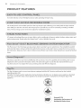 8
8
-
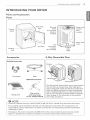 9
9
-
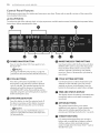 10
10
-
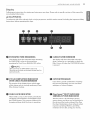 11
11
-
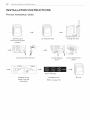 12
12
-
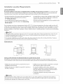 13
13
-
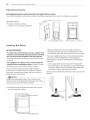 14
14
-
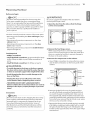 15
15
-
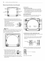 16
16
-
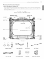 17
17
-
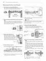 18
18
-
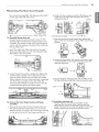 19
19
-
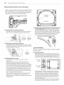 20
20
-
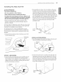 21
21
-
 22
22
-
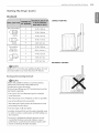 23
23
-
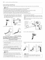 24
24
-
 25
25
-
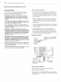 26
26
-
 27
27
-
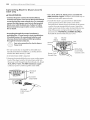 28
28
-
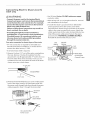 29
29
-
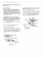 30
30
-
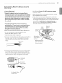 31
31
-
 32
32
-
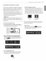 33
33
-
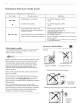 34
34
-
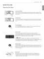 35
35
-
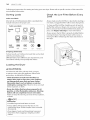 36
36
-
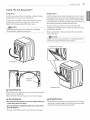 37
37
-
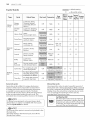 38
38
-
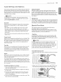 39
39
-
 40
40
-
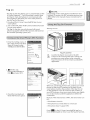 41
41
-
 42
42
-
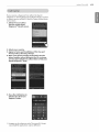 43
43
-
 44
44
-
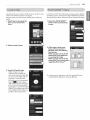 45
45
-
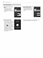 46
46
-
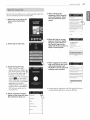 47
47
-
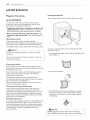 48
48
-
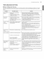 49
49
-
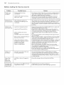 50
50
-
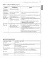 51
51
-
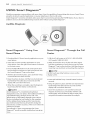 52
52
-
 53
53
-
 54
54
-
 55
55
-
 56
56
-
 57
57
-
 58
58
-
 59
59
-
 60
60
-
 61
61
-
 62
62
-
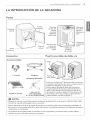 63
63
-
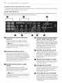 64
64
-
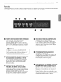 65
65
-
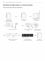 66
66
-
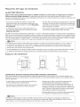 67
67
-
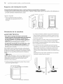 68
68
-
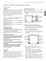 69
69
-
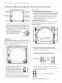 70
70
-
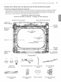 71
71
-
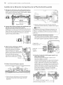 72
72
-
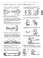 73
73
-
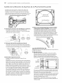 74
74
-
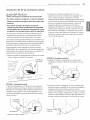 75
75
-
 76
76
-
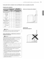 77
77
-
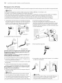 78
78
-
 79
79
-
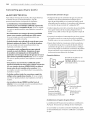 80
80
-
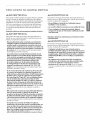 81
81
-
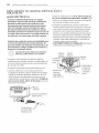 82
82
-
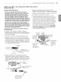 83
83
-
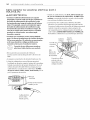 84
84
-
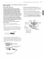 85
85
-
 86
86
-
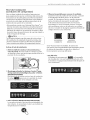 87
87
-
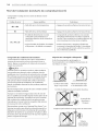 88
88
-
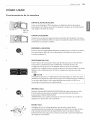 89
89
-
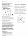 90
90
-
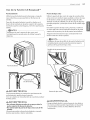 91
91
-
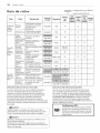 92
92
-
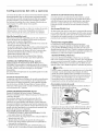 93
93
-
 94
94
-
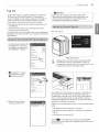 95
95
-
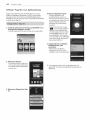 96
96
-
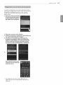 97
97
-
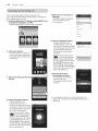 98
98
-
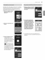 99
99
-
 100
100
-
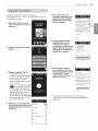 101
101
-
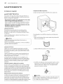 102
102
-
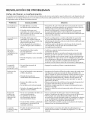 103
103
-
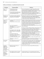 104
104
-
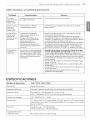 105
105
-
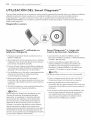 106
106
-
 107
107
-
 108
108


LG DLEY1701VE El manual del propietario
- Categoría
- Secadoras
- Tipo
- El manual del propietario
- Este manual también es adecuado para
en otros idiomas
- English: LG DLEY1701VE Owner's manual
Artículos relacionados
-
LG DLGX5781WE El manual del propietario
-
LG DLEX7700VE El manual del propietario
-
LG DLGX3371V El manual del propietario
-
LG DLEX5680V El manual del propietario
-
LG DLE1001W El manual del propietario
-
-
-
LG DLGX7188RM El manual del propietario