
Size : 420 X 297 (ram)
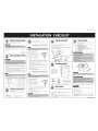
REMOVEPACKINGMATERIAL
Cut the straps oil he carton and liftthe carton off the drye*
Remove the dryer from the carton base
Check the dryer drum for all of the componen%
shown here
Literature Pack
CHECKAND CONNECTVENTING
1 Check the length of the exhaust vent it MUST NOT be longer than the
lengths shown in the chart below If it is too long, have it repaired or vented
elsewhere
2 Connect the dryer exhaust to the home exhaust system with rigid or semi
rigid metal duct DO NOT USE vinyl or foil duct for connecting the dryel
Make the transition as short as possible for best results
3 Check the exhaust hood on the outside wall Make sure it is not damaged
and that itis clear of lint buildup Make sure the damper is working properly
4 Check the exhaust for lint buildup or damage Make sure the duct is clean
and in good condition
Reeemm_ded 0 80 it 124 4 m) 41 fl (12 4 m)
_ _# 1 68 fl (207 m) 37 Jt ill 2"n)
2 5711 (]Z4 m) 33fl ri0]m)
4" (10.16 era) 3 47it (14 3 m) 29 fl (90 m)
Use only for short-run installation 0 74 it (226 m) 33 it (101 m)
1 6211 f189m) 29fl (88m)
2 51ft 1155 m) 251t 176m)
25" (6.35 ¢m) 3 41 fl (12 5 m) 21 fl (6 5 m)
CONNECT POWER CORD
For gas dryers only.
#or electric dryers proceed to step #3b on the right
Plug the dryer into a 120 VAC, 60Hz
grounded 3 prong outlet
For electric dryers only.
For gas dryers proceed to step #30 on the IdL
FOUR-WIRE POWER CORD CONNECTION
(REQUIREDinall new constructionafter Jan1,19%)
4-Wire system connections
A. External ground connector
A _ D
B. Greet, or bare copper wire of power cord
C. _f_" (]9 cm} UL listed strain relief
D. Center silver colored terminal block screw B
E
E. Neutral Grounding wire (green yellow} C J _ _ F
E Neutral wire (white or center wire}
U
i Remove the External ground connector
screw
2 Connect the ground wire (green or unwrapped} of the power cord to the
external ground connector scre_ Ifyou want to connect B(Green or bare
copper wire of power cord} to the Neutral Post without assembling with
A(cabinet ground}, call the service technician
3 Looser,or remove the center terminal block screw
4 Connect the neutral wire (white or center wire} of the power cord and the
appliance ground wire (greet, with yellow stripes} under the cenhal screw
of the terminal block
5 Connect the other wires to the outer terminal block screws Tighter, screws
B Tighten the strain relief screws
X [nsed the tab of the terminal block cover into your Dryer's rear panel slot
Secure the cover with a hold dowr, screw
THREE-WIRE POWER CORD CONNECTION
(NOT permitted in newconstructionafter Jan1,19%)
3-Wire system connections
A. External ground connector
B. Neutral grounding wire (green/yellow)
C. Cer,ter silver colored terminal block screw
D. Neuhal wire (white or center wire}
E. s/4_'(19 cm} UL listed strain relid
] Looser, or remove the center terminal block
screw
2 Connect the neutral wire (white or center wire} of the power cord to the
centel, silver colored terminal screw of the terminal block Tighter, screw
3 Connect fl:e other wires to outer terminal block screws
fighter, screws
4 Tighter, the strain relief screws
5 Insert fi:e tab of the terminal block cover into your DryeFs rear par,el slot
Secure the cover with a hold dowr, screw
CONNECT GAS SUPPLY
For gos mode_ only
1Connect the dryer to your laundry room s gas supply using a new flexible
stainless steel connector with a 3/8" NPT fitting
Never reuse an old flex connecto_
2 Securely tighten all connections be+ween the dryer and he laundry room's
gas supply Turn on the gas supply and check all connections for leaks with
a non corrosive leak detection fluid
3/8" NPT Gas /8" NPT Pipe Plug
Connection
AGA!CSA-42ertifled
Stainless Steel Shutoff: Valve
Flexible Connector
LEVELINGTHE DRYER
1To set the dryer to the
same height as the washel,
fully retract the leveling
feet by t_urningthem coun
terclockwise, then loosen
the legs by turning them
clockwise
.evel
Leveling Feet
2 Adiust the leveling feet only as
much as necessary to level the
dryec Extending the leveling fee+
more than necessary can cause
the dryer to vibra'e
HEATERCHECK
Perform the following steps to check heater operation after
removing the literature pack and any other obiects from the
drum
1Close the door and press the POWER button to turn oil the controls
2 Rotate the CYCLE SELECTOR KNOB to select a hea'ed cycle, such as
NORMAL.
3 Press the START/PAUSE button to start the cycle
After approximately one minute, open the door and check for hea" if no
heat is felt after approximately 2 minutes, consuft the troubleshooting sec
tion of the owner's manual
FINAL CHECKS
Use the following checklist to ma ke sure you have complet
ed all of the installation steps
INSTALLATION STEP
1- REMOVE PACKING MATERIAL
2 - CHECK AND CONNECT VENTING
3 - CONNECT POWER CORD
4 - CONNECT GAS SUPPLY (For gas models only)
5- LEVEL THE DRYER
6 - HEATER CHECK
Screws
For more information, refer to Installation Instructions included in the pedestal
For accessory installation instructions, consult the ins:allafion instructions
included with each accessory
LP CONVERSION KiT
SiDE VENT KIT - DV ]A XAA
STACKING KIT- SK 5AXAA
Test for proper operation by running the dryer through a
complete cycle.
Please consult your owner's manual for complete details.
P/No. DC68-O289gA-O1

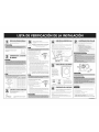
RETIRODELOSMATERIALESDEEMBALAJE
Carte bs coes e:/e] embalaje de cartTn y sep6relo de b secede a
Rete la secede a de la base de cart6n
Compruebe que el lamber de la secadora
contenga redes los componentes que se
muestran aqul
Documentaci6n
COMPROBACIONY CONEXION
DELDRENAJE
ii i i
1Compruebe =ao%tud de',condudo de vent ac@ NO debe superaras =0%tudes que
ape ecer, er,a s_guer,tetaba S es demas adeago,:,%ao epaa over,t a er,ot:a pate
2 Cor,ectee d er,aje de a secede a a sstema ded er,ajede a case conunconducto de
mete ',gdeo semk::_gde NO uf:ice unconductode vqo o @mhamet6 ice pea conecta
a secede a Hagaa 'TO'ISc6fi teaCo_¢acoma sea p'osbe pea obter,e mejo esesutades
3 Verfique a tape de d er,aje er,a paed exter:or Aseg0rese deque <1oestad@ada y de que
'io ter,gaacurvJc onesde peusesAseg0resede que e eguade deto tuncone co ecta
met,re
4 Comprueoe e conducto de d er,ajepea vefica que<1oter,ga acurrlUac@ de peuseso
d@os Ase@rese deque e Co+lductoestT'mpio y er,buer,ascondc ones
Recamendado 8 243840c'n (244"n) i24R 68c'_11i24rrl)
2 i73Z%c'n (Z4<n) i%584cm 1i0im)
4"(10,16 cm) 3 i43256c'n (43<n) 88392cm (90m)
Utilice s61opare u_ instdaci6n 8 225552c'n (226<n) 108584cm 1i01m)
decarte alcance
1 i88976cm (89rs) 88392cm I88rn)
2 i55448cm (55m) 762%cm (16m)
2,5" (6,35 cm)
3 i24968c'n (25<n) 648 % c'_1 (65r+1)
CONEXIONDELCABLEDEALIMENTACION
S6lo para secadoras a gas.
Pare secadoras eldctricas, precede al paso #3b que
aparece a la derecha
__ Enchde la secadora a un tomacordente de3 pines de 120 VCA y 60Hz con conexi6n a
tierra
$61o pare secadoras el6ctricas.
Pare secadoras a gas, precede al paso #3o que aparece
a la izquierda
CONEXION DE AL(MENTACION DE CUATRO CABLES
(REQUERIDA para odas las cons rucciones nuevas
despu6s del 1de enero de 1996)
Conexiones de sistemas de 4 cables
A. Correcter a tierra externo
A _ D
B. Cableverdeo decobredesnu@delcablededimentaci6n <
C. Protecci@_ cor_tra los tiror, es car, certifi
caci6r_ UL de 34" (1,9cm} B
E
D. Tarnillo cer_tral de color plateado del
bloque de terminales O " _ x F
E. Cable a tierra r_eutro (verde/amarillo}
E Cable r_eutro (cable blanco o cer_tlal}
i Retire el tornillo del correcter a tierra externo
2 Cor_ecte el cable atie_ra (verde o sincubierta) del cable de abmer_tacide al
tornillo del correcter a fierra externo Sidesea cor_ectar B (cable de cobre
verde o desr,udo del cable de alimerCaci@_) al terminal neutro sin mor_tarlo
er_A (conexi6r_ a flerra del gabinetd, Ilame al servicio tTcr_ico
3 Afloje o retire el tomillo cer_tlal del bloque de terminales
4 Cor_ecte el cable r,eutro (cable blanco o cer_hal} del cable de alimer_t
aci@_y el cable a tierra de] electlodom@stico (verde cor_frar_as amadllas)
debajo del tomillo cer_tlal del bloque de terminales
5 Conede as aem6scabes a ostorrd as e£ernosde hague ae terminaiesAJusleostornlos
6 Ajuste los families car, dispositivo de alivio de ter_side
Z Inserte lalerlgJeta de la cubierta del bloque de terminales erl la rarlura del
panel posterior de la secadora Asegure la cubierta con Urltornillo de s,;jeci6n
CQNEXION DE ALIMENTAClON DE TRES CABLES
(NO se permie e: co: slrucc onesn,;evasdespu@ de 1de e:'e_o de 1996)
Conexianes de sistemas de 3 cables
A. Correcter a tierra externo
B. Cable a tierra r_eutro (verde amarillo)
C. Tomi_ cer-ra decoor p!aleadode L';oquedeterrlinae_
D. Cable r_e,;tlo (cable blar_co ocer_tlal)
E. Piotecci6r_ cor_tla los tiror_es cor_certificacide
UL de 34 +' (1,9cmJ
i Afloje o retire d tomillo cer_tral del bloque
de terminales
2 Conecte el cable neutro (cable blanco o cent'al) del cable de al _e_'tac 6:,a la're
renal deto Iio ce_'tral de cdo plaleado del bloque de te m_abs A;usie elto Iio
3 Conede as aerl,_scabes a iostorrdasexternos@ hague geterminaies Ajusteostorrd as
4 Ajuste los tornillos cor_dispositivo de alivio de ter_side
5 Inserte la lengdeta de la cub erta del bloque de term hales en la ranura del
panel poster or de la secadora Asegure la cubierta con un tornillo de su;eci6n
CONEXlONDELSUMINISTRODEGAS
561o pare modelos a gas
1Conecte la secadora al suministlo de gas de la sala de lavado mediante un
conector flexible de acero inoxidable con una rosca estTndar de tuberTa
de 3/8"
Nunca vuelva a utilizar un conector flexible viejo
2 Asegure firmemente todas las cortex ones entre la secadera y el sumnistro de gas
Abra el sumnistro de gas y compruebe que todas las corlexiones pare vet que no
haya p@d desreed ante el usa de un@ida de detecci6n de _6rddes nocorrosive
3/8" NPT Gas /8" NPT Pipe Plug
Connection
AGA!CSA-Certifled
Stainless Steel Shutoff Valve
Flexible Connector
NIVELACIONDELASECADORA
1 Para colocar la seca
dora a la rqsma alfura
que la lavadora, retraiga
completamente las paras
niveladoras gir6ndolas
en sentido contrario a las
agujas del relo], luego
afloje las paras gir6ndolas
en el senfido de las agujas
del relo]
ii
ii
ii
\ Retract fully / _ Then loosen /
.evel
Leveling Feet
2 Ajuste las patas niveladoras
sTIo Io necesario para nivelar
la secadora Extender las paras
niveladoras rots de Io necesario
puede hacer que la secadora
vibre
COMPROBACIONDELCALENTADOR
Lleve a cabo los siguientes pasos para comprobar el fun
cionamiento del calentador tras quiar la documentaci6n y
cualquier otto objeto del fambo_
1Cerre a pueda y presbne d bo16n POWER{ENCENDIDO) pare encender as co _t<oes
2 G_e d DIALSELECTORD_ CICLOSpare se ecconar d cco de cao_, par e;emp o,
NORMAL
3 Presone e bo16nSTART/PAUSE(INICIO PAUSA)pare ncar e cco
_as aprox madamerle unmnulq aba a pueda y compruebe que se se:'ta cao_ S
noseserle caor 1'as aprox madem÷qe 2 mhulas,consu'3e',asecc 6nde souci6n de
probemas dd manua de usuaro
COMPROBACIONES FINALES
Utilice la siguiente lista de vedficaci6n para asegurarse de
haber completado redes los pasos de instalaci@/
PASO DE INSTALACI6N
1- RETIRe DE LOS MATERIALES DE EMBALAJE
2-COMPROBACION Y CONEXION DEL DRENAJE
3 - CONEXION DEL CABLE DE ALIMENTACION
4 - CONRXION DRL SUMINISTRODR GAS (561opare los modelosa gas)
5 - NIVELACION DE LA SECADORA
6 - COMPROBACION DEL CALENTADOR
Screws
Para obtener mas in$ormaci6n, consulfe las [nsfrucciones de inCalaci6n inclui
des en el pedestal
Para obtener ins rucciones acerca de la ins alaci@l de los accesodos,
consulle las instrucciones de instalaci6n induidas con cada accesodo.
KIT DE CONVERSION LP
KIT DE VENTILACiON LATERAL- DV ]AXAA
KIT DE APILAMIENTO SK 5AXAA
Pruebe la operaci6n correcta poniendo a funcionar la
secadora par un ciclo complete.
Consulte el Manual del usuario para obtener m6s detalles.
PIN DC68-O289OA=01
-
 1
1
-
 2
2


Kenmore 40289032011 Guía de instalación
- Tipo
- Guía de instalación
- Este manual también es adecuado para
en otros idiomas
Artículos relacionados
Otros documentos
-
Kenmore Elite 79661622310 Manual de usuario
-
LG DLEY1701WE El manual del propietario
-
LG DLEX7700VE El manual del propietario
-
LG DLEY1701W El manual del propietario
-
LG DLEX5680V El manual del propietario
-
Samsung DV395ETPAWR/A1-00 El manual del propietario
-
LG DLGX5781WE El manual del propietario
-
LG DLEX3250R El manual del propietario