MTD 21AA40M1029 El manual del propietario
- Categoría
- Mini cultivadores
- Tipo
- El manual del propietario
Este manual también es adecuado para

Safe Operation Practices • Set-Up • Operation • Maintenance • Service • Troubleshooting • Warranty
L
Rear Tine CRTTiller -- 400
MTD LLC, P.O. BOX 361131 CLEVELAND, OHiO 44136-0019
PrintedInUSA FormNo.769-06423
(November15,2010)

ToTheOwner
1
ThankYou
Thank you for purchasing an MTD Garden Tiller. It was carefully
engineered to provide excellent performance when properly
operated and maintained.
Please read this entire manual prior to operating the equipment.
It instructs you how to safely and easily set up, operate and
maintain your machine. Please be sure that you, and any other
persons who will operate the machine, carefully follow the
recommended safety practices at all times. Failure to do so could
result in personal injury or property damage.
All information in this manual is relative to the most recent
product information available at the time of printing. Review
this manual frequently to familiarize yourself with the machine,
its features and operation. Please be aware that this Operator's
Manual may cover a range of product specifications for various
models. Characteristics and features discussed and/or illustrated
in this manual may not be applicable to all models.
We reserve the right to change product specifications, designs
and equipment without notice and without incurring obligation.
If you have any problems or questions concerning the machine,
phone your local authorized MTD service dealer or contact us
directly. MTD's Customer Support telephone numbers, website
address and mailing address can be found on this page. We want
to ensure your complete satisfaction at all times.
Throughout this manual, all references to right and left side of the
machine are observed from the operating position
Tableof Contents
Safe Operation Practices ........................................ 3
Assembly & Set-Up .................................................. 7
Controls & Features ................................................ 10
Operation ................................................................ 11
Maintenance & Adjustments ................................. 16
Service ..................................................................... 18
Troubleshooting .................................................... 20
Replacement Parts ................................................. 21
Warranty ................................................................ 24
RecordProductinformation
Before setting up and operating your new equipment, please
locate the model plate on the equipment and record the
information in the provided area to the right. You can locate the
model plate by standing at the operator's position and looking
down at the front right corner of the tine shield. This information
will be necessary, should you seek technical support via our web
site, Customer Support Department, or with a local authorized
service dealer.
MODEL NUMBER
DDDDDDDDDDD
SERIAL NUMBER
[3N[3N[3N[3N[3ND
CustomerSupport
Please do NOT return the machine to the retailer or dealer without first contacting our Customer Support Department.
If you have difficulty assembling this product or have any questions regarding the controls, operation, or maintenance of
this machine, you can seek help from the experts. Choose from the options below:
0 Visit us on the web at www.mtdproducts.com
0 Call a Customer Support Representative at (800) 800-7310 or (330) 220-4683
0 Write us at MTD LLC • RO. Box 361131 • Cleveland, OH • 44136-0019

ImportantSafeOperationPractices
2
,A
WARNING! This symbol points out important safety instructions which, if not followed,
could endanger the personal safety and/or property of yourself and others. Read and follow
all instructions in this manual before attempting to operate this machine. Failure to comply
with these instructions may result in personal injury.
When you see this symbol. HEED ITS WARNING!
CALIFORNIA PROPOSITION 65
WARNING! Engine Exhaust, some of its constituents, and certain vehicle components
contain or emit chemicals known to State of California to cause cancer and birth defects
or other reproductive harm.
WARNING! Battery posts, terminals, and related accessories contain lead and lead
compounds, chemicals known to the State of California to cause cancer and reproductive
harm. Wash hands after handling
DANGER! This machine was built to be operated according to the safe operation practices in
this manual. As with any type of power equipment, carelessness or error on the part of the
operator can result in serious injury. This machine is capable of amputating fingers, hands,
toes and feet. Failure to observe the following safety instructions could result in serious
injury or death.
Training 2.
1. Read, understand, and follow all instructions on the
machine and in the manual(s) before attempting to
assemble and operate. Keep this manual in a safe place for
future and regular reference and for ordering replacement
parts.
2. Be familiar with all controls and their proper operation.
Know how to stop the machine and disengage them
quickly.
3. Never allow children under 14 years of age to operate this
machine. Children 14 and over should read and understand
the instructions and safe operation practices in this manual
and on the machine and be trained and supervised by an
adult.
4_
5.
Never allow adults to operate this machine without proper
instruction.
Keep the area of operation clear of all persons, particularly
small children and pets. Stop machine if anyone enters the
area.
Preparation
Thoroughly inspect the area where the equipment is to
be used. Remove all stones, sticks, wire, and other foreign
objects which could be tripped over and cause personal
injury.
Wear sturdy, rough-soled work shoes and close fitting
slacks and shirt. Loose fitting clothes or jewelry can be
caught in moving parts. Never operate this machine in bare
feet or sandals.
3. Disengage clutch levers and shift (if provided) into neutral
('N") before starting the engine.
4. Never leave this machine unattended with the engine
running.
5. Never attempt to make any adjustments while engine is
running, except where specifically recommended in the
operator's manual.
SafeHandlingofGasoline:
To avoid personal injury or property damage use extreme care
in handling gasoline. Gasoline is extremely flammable and the
vapors are explosive. Serious personal injury can occur when
gasoline is spilled on yourself or your clothes which can ignite.
Wash your skin and change clothes immediately.
a. Use only an approved gasoline container.
b. Never fill containers inside a vehicle or on a truck
or trailer bed with a plastic liner. Always place
containers on the ground away from your vehicle
before filling.

d_
e_
fl
g.
When practical, remove gas-powered equipment
from the truck or trailer and refuel it on the ground.
If this is not possible, then refuel such equipment on
a trailer with a portable container, rather than from a
gasoline dispenser nozzle.
Keep the nozzle in contact with the rim of the fuel
tank or container opening at all times until fueling is
complete. Do not use a nozzle lock-open device.
Extinguish all cigarettes, cigars, pipes and other
sources of ignition.
Never fuel machine indoors.
Never remove gas cap or add fuel while the engine
is hot or running. Allow engine to cool at least two
minutes before refueling.
h. Never over fill fuel tank. Fill tank to no more than 1/2
inch below bottom of filler neck to allow space for
fuel expansion.
i. Replace gasoline cap and tighten securely.
j. If gasoline is spilled, wipe it off the engine and
equipment. Move unit to another area. Wait 5
minutes before starting the engine.
k. To reduce fire hazards, keep machine free of grass,
leaves, or other debris build-up. Clean up oil or fuel
spillage and remove any fuel soaked debris.
I. Never store the machine or fuel container inside
where there is an open flame, spark or pilot light
as on a water heater, space heater, furnace, clothes
dryer or other gas appliances.
Operation
1. Do not put hands or feet near rotating parts. Contact with
the rotating parts can amputate hands and feet.
2. Do not operate machine while under the influence of
alcohol or drugs.
3. Never operate this machine without good visibility or light.
Always be sure of your footing and keep a firm hold on the
handles.
4. Keep bystanders away from the machine while it is in
operation. Stop the machine if anyone enters the area.
5. Be careful when tilling in hard ground. The tines may catch
in the ground and propel the tiller forward. If this occurs,
letgo of the handle bars and do not restrain the machine.
6. Exercise extreme caution when operating on or crossing
gravel surfaces. Stay alert for hidden hazards or traffic. Do
not carry passengers.
7. Never operate the machine at high transport speeds on
hard or slippery surfaces.
8. Exercise caution to avoid slipping or falling.
9. Look down and behind and use care when in reverse or
pulling machine towards you.
10. Start the engine according to the instructions found in this
manual and keep feet well away from the tines at all times.
11. After striking a foreign object, stop the engine, disconnect
the spark plug wire and ground against the engine.
Thoroughly inspect the machine for any damage. Repair
the damage before starting and operating.
12. Disengage all clutch levers (if fitted) and stop engine
before you leave the operating position (behind the
handles). Wait until the tines come to a complete stop
before unclogging the tines, making any adjustments, or
inspections.
13. Never run an engine indoors or in a poorly ventilated area.
Engine exhaust contains carbon monoxide, an odorless
and deadly gas.
14. Muffler and engine become hot and can cause a burn. Do
not touch.
15. Use caution when tilling near fences, buildings and
underground utilities. Rotating tines can cause property
damage or personal injury.
16. Do not overload machine capacity by attempting to till soil
too deep at too fast of a rate.
17. If the machine should start making an unusual noise or
vibration, stop the engine, disconnect the spark plug wire
and ground it against the engine. Inspect thoroughly for
damage. Repair any damage before starting and operating.
18. Keep all shields, guards, and safety devices in place and
operating properly.
19. Never pick up or carry machine while the engine is running.
20. Use only attachments and accessories approved by the
manufacturer. Failure to do so can result in personal injury.
21. If situations occur which are not covered in this manual, use
care and good judgement. Contact Customer Support for
assistance and the name of you nearest servicing dealer..
Maintenance & Storage
1. Keep machine, attachments and accessories in safe
working order.
2. Allow a machine to cool at least five minutes before
storing. Never tamper with safety devices. Check their
proper operation regularly.
3. Check bolts and screws for proper tightness at frequent
intervals to keep the machine in safe working condition.
Also, visually inspect machine for any damage.
4. Before cleaning, repairing, or inspecting, stop the engine
and make certain the tines and all moving parts have
stopped. Disconnect the spark plug wire and ground it
against the engine to prevent unintended starting.
5. Do not change the engine governor settings or over-speed
the engine. The governor controls the maximum safe
operating speed of engine.
6. Maintain or replace safety and instruction labels, as
necessary.
7. Follow this manual for safe loading, unloading,
transporting, and storage of this machine.
8. Always refer to the operator's manual for important details
if the machine is to be stored for an extended period.
4 I SECTION 2 -- IMPORTANT SAFE OPERATION PRACTICES

9.
10.
11.
If the fuel tank has to be drained, do this outdoors.
Observe proper disposal laws and regulations for gas, oil,
etc. to protect the environment.
According to the Consumer Products Safety Commission
(CPSC) and the U.S. Environmental Protection Agency (EPA),
this product has an Average Useful Life of seven (7) years,
or 130 hours of operation. Atthe end of the Average Useful
Life have the machine inspected annually by an authorized
service dealer to ensure that all mechanical and safety
systems are working properly and not worn excessively.
Failure to do so can result in accidents, injuries or death.
Notice Regarding Emissions
Engines which are certified to comply with California and federal
EPA emission regulations for SORE (Small Off Road Equipment)
are certified to operate on regular unleaded gasoline, and
may include the following emission control systems: Engine
Modification (EM), Oxidizing Catalyst (OC), Secondary Air
Injection (SAI) and Three Way Catalyst (TWC) if so equipped.
SparkArrestor
_ ARNING! This machine is equipped with an
internal combustion engine and should not be used
on or near any unimproved forest-covered,
brushcovered or grass-covered land unless the
engine's exhaust system is equipped with a spark
arrestor meeting applicable local or state laws (if
any).
Ira spark arrestor is used, it should be maintained in effective
working order by the operator. In the State of California the
above is required by law (Section 4442 of the California Public
Resources Code). Other states may have similar laws. Federal laws
apply on federal lands.
A spark arrestor for the muffler is available through your
nearest engine authorized service dealer or contact the service
department, RO. Box 361131 Cleveland, Ohio 44136-0019.
SECTION 2 -- IMPORTANT SAFE OPERATION PRACTICES S

Safety Symbols
This page depicts and describes safety symbols that may appear on this product. Read, understand, and follow all instructions on the
machine before attempting to assemble and operate.
A
READ THE OPERATOR'S MANUAL(S)
Read, understand, and follow all instructions in the manual(s) before attempting to
assemble and operate
WARNING-- ROTATING TINES
Do not put hands or feet near rotating parts. Contact with the rotating parts can amputate
hands and feet.
WARNING-- ROTATING TINES
Do not put hands or feet near rotating parts. Contact with the rotating parts can amputate
hands and feet.
WARNING--GASOLINE ISFLAMMABLE
Allow the engine to cool at least two minutes before refueling.
WARNING-- CARBON MONOXIDE
Never run an engine indoors or in a poorly ventilated area. Engine exhaust contains carbon
monoxide, an odorless and deadly gas.
WARNING-- HOT SURFACE
Engine parts, especially the muffler, become extremely hot during operation. Allow engine
and muffler to cool before touching.
WARNING! Your Responsibility--Restrict the use of this power machine to persons who read, understand and
follow the warnings and instructions in this manual and on the machine.
SAVETHESEINSTRUCTIONS!
6 I SECTION 2 -- IMPORTANT SAFE OPERATION PRACTICES

Assembly& Set-Up
3
Contentsof Carton
OneTiller
One Hardware Pack
One Handlebar Assembly
One Engine Operator's Manual
One Operator's Manual
WARNING! To prevent personal injury or property
damage, do not start the engine until all assembly
steps are complete and you have read and
understand the Safe Operation Practices Section
and the Operating Section in this manual.
Assembly
UnpackingInstructions
NOTE:While unpacking, do not severely bend any of the control
cables.
1. The tiller is heavy, do not attempt to remove it from the
shipping platform until instructed to do so.
2. Remove all parts from the carton. Check that you have the
items listed in the Contents of Carton list (contact your
local dealer or the factory if items are missing or damaged).
3. Remove any packaging material from the carton. Remove
any staples from the bottom of the carton and remove the
carton from the shipping platform.
Handle
NOTE: All references to the right or left side of the tiller are from
the operator's position.
1. Install the handle onto the tiller using the hardware pre-
installed on the handle mounting brackets. This consists of
a %6-18 x 3.00" hex bolt, a handle crank assembly, retainer
bracket and two %6-18 flange lock nuts. Remove this
hardware from the handle mounting brackets on the tiller.
2. Insert the handle into the handle mounting brackets, lining
up the pre-d filled holes. Insert the %6-18 x 3.00" hex bolt
in the bottom hole from the left hand side through to the
other side. Place the round hole end of the hex retainer
bracket over the hex bolt and secure loosely with a bell
washer and %0-18 flange lock nut removed earlier.
NOTE:The bell washer should be positioned with the top
of the bell shape towards the hex nut which will create
tension and further secure the flange lock nut once
tightened. Do not tighten this hardware at this time.
3.
4.
Install the handle-crank adjustment rod into the top hole of
the mounting bracket from the left hand side of the handle
assembly, secure with the other flange lock nut previously
removed. Fit the hex end of the retainer bracket over the
flange lock nut. See Fig. 3-1.
Figure 3-1
Tighten the hex bolt installed in Step 2 at this time. Be
careful not to overtighten this hardware.

5_
The handle should be adjusted so that when the tiller
is digging 3-4" into the soil, the handle falls to about
waste-high. To adjust the handle, simply loosen the handle
adjustment crank, move the handle to the desired height
and retighten the adjustment crank. See Fig. 3-2.
i
3_
2_
3_
NOTE:Test the function of the forward drive bail, lift the
bail to the handle and release it. The bail should return to
its neutral position. If it doesn't, contact your local dealer
for technical assistance.
Carefully unwrap the reverse clutch cable (Red end fitting)
from its shipping position. Pull the cable up through the
top hole of the cable bracket and push the cable connector
up through the hole until the groove in the connector
snaps into place. See Fig. 3-3.
Place the Z-connector into the hole in the reverse clutch
handle assembly from the inside of the handle to the
inside. See Fig. 3-3.
NOTE:Test the function of the reverse clutch by pulling the
reverse handle and releasing it. The handle should return
to its neutral position. If it doesn't, contact your local dealer
for technical assistance.
Clip the cables into the cable guides located on the handle
assembly panel as seen in Fig. 3-4.
Attachingthe Cables
Figure 3=2
Forward ClutchCable
Carefully unwrap the forward clutch cable (Black end
fitting) from its shipping position. Pull the cable up
through the bottom hole of the cable bracket and push the
cable connector up through the hole until the groove in
the connector snaps into place. See Fig. 3-3.
2_
Reverse
Clutch
Cable
Figure 3-3
Place the Z-connector into the hole in the forward clutch
bail from the outside of the bail in. See Fig. 3-3.
Figure 3-4
8 I SECTION 3 -- ASSEMBLY & SET-UP

MoveTillerOff Crate
To roll the tiller off the shipping platform, put the wheels in
freewheel, if they are not already from the factory, as follows:
1. Place a sturdy block under the transmission to raise one
wheel about 1" off the ground. Remove the wheel drive pin
from the wheel hub and wheel shaft. See Fig. 3-5.
Wheel Drive Pin
Wheel Shaft
2_
Figure 3-5
Slide the wheel fully inward on the wheel shaft. Reinstall
the wheel drive pin through the wheel shaft only (not
through the wheel hub). See Fig. 3-5. The wheel should
now spin freely (freewheel) on the wheel shaft. Repeat with
the other wheel.
3. Use the handlebar to roll the tiller to a flat area.
Set-Up
TirePressure
Check the air pressure with a tire gauge. Deflate or inflate the
tires equally to between 15and 20 PSI. DO NOT EXCEED 20 P.S.I.
NOTE: Be sure that both tires are inflated equally or the tiller will
pull to one side.
Gas& OilFillUp
_L ARNING! Use extreme care when handling
gasoline. Gasoline is extremely flammable and the
vapors are explosive. Never fuel the machine
indoors or while the engine is hot or running.
Extinguish cigarettes, cigars, pipes and any other
sources of ignition.
Service the engine with gasoline and oil as instructed in the
Engine Operator's Manual packed separately with your tiller.
Read the instructions carefully.
Transmissi0n/Gear0il
The transmission was filled with gear oil at the factory. However,
you should check the gear oil level at this time to make certain
it is correct. Refer to the Maintenance & Adjustments section for
instructions on checking the transmission/gear oil.
NOTE: Do not operate the tiller if the gear oil level is low. Doing
so will result in severe damage to the transmission components.
SECTION 3 -- ASSEMBLY& SET-UP 9

Controls& Features
4
Forward Clutch Bail
& Tine Engagement
Depth Regulator
Jght Adjustment
Side Shield
Tine Shield
Tines
Drive Pin
Figure 4-1
NOTE:This Operator's Manual covers several garden tiller
models. The tiller depicted may differ from yours.
WARNING! Before operating your machine,
carefully read and understand all safety, controls
and operating instructions in this manual and on the
decals on the machine. Failure to follow these
instructions can result in serious personal injury.
EngineControls
For detailed information on all engine controls refer to the
separate Engine Operator's Manual.
ReverseHandle
The Reverse Handle controls the reverse drive of the wheels and tines.
ForwardClutchBail& TineEngagement
The forward clutch bail controls the engagement of the forward
drive of the wheels and tines.
Tines
Your tiller's tines are a series of hoes arranged on a revolving
power-driven shaft.
DepthRegulatorLever
This lever controls the tilling depth of the tines. Pull the lever back
and slide it up or down to engage the notched height settings.
HandlebarHeightAdjustment
The handlebar height is adjustable to three different settings. In
general, adjust the handlebars so they are at waist level when the
tines are 3-4" in the ground.
RearTineShield
The rear tine shield protects the operator from flying debris
while also smoothing out freshly tilled soil.
SideShield
The side shield is used to maintain clear even rows and may be
adjusted to one of five different positions.
WheelDrivePins
Each wheel is equipped with a wheel drive click pin that secures
the wheel to the wheel shaft. The wheels can be positioned in
either a WHEEL DRIVE or a FREEWHEEL mode.

Operation
WARNING! Before operating your machine,
carefully read and understand this manual and all of
its safety, operating and maintenance sections and
instructions, along with all of the decals on the
machine. Failure to follow these instructions can
result in serious personal injury.
introduction
Read this Operation Section and the Engine Operator's Manual
before you start the engine. Then, take the time to familiarize
yourself with the basic operation of the tiller before using it in
the garden.
Find an open, level area and practice using the tiller controls without
the tines engaging the soil (put tines in "transport" setting).
Only after you've become completely familiar with the tiller
should you begin using it in the garden.
Break-inOperation
Perform the following maintenance after the first five (5) hours of
new operation (see Maintenance & Adjustments Section in this
manual).
1. Change engine oil.
2. Check for loose or missing hardware on unit. Tighten or
replace as needed.
3. Check transmission gear oil level. See the Maintenance &
Adjustments section.
Starting& Stopping
Pre-StartChe(klist
2.
3.
4.
5.
6.
With the spark plug wire disconnected from the spark plug,
perform the following checks and services before each use:
1. Read the Safety and Controls Sections in this manual. Read
the Engine Maintenance section in this manual.
Put the wheels in the WHEEL DRIVE position (wheel pins
must be through holes in wheel hubs and wheel shaft).
Check unit for loose or missing hardware. Service as
required.
Check engine oil level. See the Engine Operator's Manual.
Check that all safety guards and covers are in place.
Check air cleaner and engine cooling system. See the
Engine Operator's Manual.
8.
WARNING! GASOLINE IS HIGHLY FLAMMABLE AND
ITSVAPORS ARE EXPLOSIVE. Follow the gasoline
safety rules in the Important Safe Operations
Practices section of this manual. Failure to follow
gasoline safety instructions can result in serious
personal injury and property damage.
Fill the fuel tank with gasoline according to the directions
in the Engine Operator's Manual. Follow all instructions and
safety rules carefully.
Attach the spark plug wire to the spark plug.
Starting the Engine
WARNING! To help prevent serious personal injury
or damage to equipment, put both wheels in the
WHEEL DRIVE position. Never have wheels in
FREEWHEEL position when the engine is running.
When the wheels are in FREEWHEEL, they do not
hold back the tiller and the tines could propel the
tiller rapidly forward or backward. Put the Forward
Clutch Bail in neutral (disengaged) positions by
releasing the lever.
WARNING! Never run the engine indoors or in an
enclosed, poorly ventilated area. Engine exhaust
contains carbon monoxide, an odorless and deadly
gas. Avoid the engine muffler and nearby areas.
Temperatures in these areas may exceed 150° F.
1. Complete the Pre-Start Checklist above on this page.
2. Put the wheels in the WHEEL DRIVE position.
3. Move the depth regulator lever all the way down to the
"travel" position, so that the tines clear the ground. To
change the depth setting, pull back on the depth regulator
lever (A) and lift up or down (B), then release the lever (C) to
secure in the desired position. See Fig, 5-1.
4.
5.
Figure 5-1
Release all of the controls on the tiller.
Start the engine as instructed in the Engine Operator's
Manual.
11

Stoppingthe Engine
1. To stop the wheels and tines, release the Forward Clutch
Bail.
2. Refer to the Engine Operator's Manual for instructions on
stopping the engine.
ToEngageDrive&Tines
1.
For forward motion of the wheels and power to the tines
pull the Forward Clutch Bail up against the handlebar.
Release the bail to stop the forward motion of wheels and
tines.
2. When tilling, relax and let the wheels pull the machine
while the tines dig. Walk behind and a little to one side of
the tiller. Use one hand, yet keep a light -- but secure --
grip on the handlebar while keeping your arm loose.
3. Let the tiller move at its own pace and do not push down
on the handlebars to try and force the tines to dig deeper
-- this takes weight off the wheels and reduces traction.
WARNING! Do not push down on the handlebars
to try to make the tiller till more deeply. This
prevents the wheels from holding the tiller back and
can allow the tines to rapidly propel the tiller
forward, which could result in loss of control,
property damage, or personal injury.
Tomovein reverse:
1. Release the forward Clutch Bail. Then lift the handlebar
until the tines are off the ground.
2. Pull back on the Reverse Lever, and walk backwards with
the machine
NOTE: In reverse mode, the tines will reverse rotation.
3. If longer distances need to be covered in reverse, shut off
the engine, then place the two wheels in FREEWHEEL.
Turningthe Tiller
1. Practice turning the tiller in a level, open area. Be very
careful to keep your feet and legs away from the tines.
2. To begin a turn, lift the handlebars until the tines are out
of the ground and the engine and tines are balanced over
the wheels.
3.
With the tiller balanced, push sideways on the handlebar to
steer in the direction of the turn. After turning, slowly lower
the tines into the soil to resume tilling.
SettingTheDepth
Tilling depth is controlled by the depth stake which can be
adjusted to five different settings. Adjust the side shields as you
adjust the depth stake.
_ ARNING! Be certain spark plug wire is
disconnected and grounded against the engine
when performing any adjustments.
When using the tiller for the first time, use the second
adjustment hole from the top (1" of tilling depth).
When breaking up sod and for shallow cultivation, use the
setting which gives 1" of tilling depth (second hole from
the top). Place the side shields in their lowest position.
For further depth, raise the depth stake and side shields
and also make one or two more passes over the area.
When tilling loose soil, the depth stake may be raised to its
highest position (use bottom adjustment hole) to give the
deepest tilling depth. Raise the side shields to their highest
position.
To transport tiller, lower the depth stake (use top
adjustment hole).
To adjust the depth stake, pull back on the depth adjustment
bracket (A) and push up or down (B) until the bracket reaches the
desired position, see Fig. 5-1, then release the bracket (C).
To adjust the side shields (if so equipped), remove the wing nuts.
Move the side shield to the desired position and replace the wing
nuts. Tighten securely. See Fig. 5-2.
Figure 5-2
12 J SECTION S-- OPERATION

Clearingthe Tines
The tines have a self-clearing action which eliminates most
of the tangling of debris. However, occasionally dry grass,
stringy stalks or tough vines may become tangled. Follow
these procedures to help avoid tangling and to clear the
tines, if necessary.
To reduce tangling, set the depth regulator deep enough
to get maximum "chopping" action as the tines chop the
material against the ground. Also, try to till under crop
residues or cover crops while they are green, moist and
tender.
While tilling, try swaying the handlebars from side to side
(about 6" to 12"). This "fishtailing" action often clears the
tines of debris.
WARNING! Before clearing the tines by hand, stop
the engine, allow all moving parts to stop and
disconnect the spark plug wire. Failure to follow this
warning could result in personal injury.
TillingTips& Techniques
TillingDepth
i_ WARNING! Before tilling, contactyour telephone
or utilities company and inquire if underground
equipment or lines are used on your property. Do
not till near buried electric cables, telephone lines,
pipes or hoses.
This is a CRT (counter-rotating tine) tiller. As the wheels
pull forward, the tines rotate backward. This creates an
"uppercut" tine action which digs deeply, uprooting soil
and weeds. Don't overload the engine, but dig as deeply
as possible on each pass. On later passes, the wheels may
tend to spin in the soft dirt. Help them along by lifting up
slightly on the handlebar (one hand, palm up, works most
easily).
Avoid the temptation to push down on the handlebars in
an attempt to force the tiller to dig deeper. Doing so takes
the weight off the powered wheels, causing them to lose
traction. Without the wheels to hold the tiller back, the
tines will attempt to propel the tiller backward, towards the
operator.
When cultivating (breaking up the surface soil around the
plants to destroy weeds, see Fig. 5-3), adjust the tines to
dig only 1" to 2" deep. Using the shallow tilling depth helps
prevent injury to the plants whose roots often grow close
to the surface. If needed, lift up on the handlebars slightly
to prevent the tines from digging too deeply. (Cultivating
on a regular basis not only eliminates weeds, it also loosens
and aerates the soil for better moisture absorption and
faster plant growth.) Watering the garden area a few days
prior to tilling will make tilling easier, as will letting the
newly worked soil set for a day or two before making a
final, deep tilling pass.
Figure 5-3
ChoosingCorrectWheel& TineSpeeds
With experience, you will find the tilling depth and tilling speed
combination that is best for your garden. Set the engine throttle
lever at a speed to give the engine adequate power and yet
allow it to operate at the slowest possible speed until you have
achieved the maximum tilling depth you desire. Faster engine
speeds may be desirable when making final passes through the
seedbed or when cultivating. Selection of the correct engine
speed, in relation to the tilling depth, will ensure a sufficient
power level to do the job without causing the engine to labor.
SECTION S -- OPERATION 13

SuggestedTilling Patterns
When preparing a seedbed, go over the same path twice in
the first row, then overlap one-half the tiller width on the
rest of the passes. See Fig. 5-4.
f
If the garden size will not permit lengthwise and then
crosswise tilling, then overlap the first passes by one-half
a tiller width, followed by successive passes at one-quarter
width. See Fig. 5-6.
Figure 5-4
When finished in one direction, make a second pass at a
right angle, as shown in Fig. 5-5. Overlap each pass for the
best results (in very hard ground, it may take three or four
passes to thoroughly pulverize the soil.)
r _ 7
Figure 5-5
Figure 5-6
Tillingona Slope
WARNING! Do not operate the tiller on a slope too
steep for safe operation. Till slowly and be sure you
have good footing. Never permit the tiller to
freewheel down slopes. Failure to follow this
warning could result in personal injury.
I. Till only on moderate slopes, never on steep ground where
the footing is difficult.
2. Tilling up and down slopes is recommended over terracing.
Tilling vertically on a slope allows maximum planting area
and also leaves room for cultivating.
NOTE:When tilling on slopes, be sure the correct oil level
is maintained in the engine (check every one-half hour
of operation). The incline of the slope will cause the oil to
slant away from its normal level and this can starve engine
parts of required lubrication. Keep the motor oil level at the
full point at all times.
Tilling UpandDownaSlope
I. To keep soil erosion to a minimum, be sure to add enough
organic matter to the soil so that it has good moisture-
holding texture and try to avoid leaving footprints or wheel
marks.
2.
When tilling vertically, try to make the first pass uphill
as the tiller digs more deeply going uphill than it does
downhill. In soft soil or weeds, you may have to lift the
handlebars slightly while going uphill. When going
downhill, overlap the first pass by about one-half the width
of the tiller.
SECTION 5-- OPERATION

TerraceGardening
1. To create a terrace, start at the top of the slope and work
down. Go back and forth across the first row as shown in
Fig. 5-7.
e
O
I_'REPEAT
Figure 5-7
2.
Each succeeding lower terrace is started by walking below
the terrace you are preparing. For added stability of the
tiller, always keep the uphill wheel in the soft, newly tilled
soil. Do not till the last 12" or more of the downhill outside
edge of each terrace. This untilled strip helps prevent the
terraces from breaking apart and washing downhill. It also
provides a walking path between the rows.
Loading& Unloadingthe Tiller
WARNING! Loading and unloading the tiller into a
vehicle is potentially hazardous and doing so is not
recommended unless absolutely necessary, as this
could result in personal injury or property damage.
However, if you must load or unload the tiller, follow the
guidelines given next.
Before loading or unloading the tiller, stop the engine, wait
for all parts to stop moving, disconnect the spark plug wire
and let the engine and muffler cool.
The tiller is too heavy and bulky to be safely lifted by one
person. Two or more people should share the load.
Use sturdy ramps and manually -- with the engine shut
off-- roll the tiller into and out of the vehicle. Two or more
people are needed to do this.
The ramps must be strong enough to support the
combined weight of the tiller and any handlers. The ramps
should provide good traction to prevent slipping; they
should also have side rails to guide the tiller along the
ramps; and they should have a locking device to secure
them to the vehicle.
The handlers should wear sturdy footwear that will help to
prevent slipping.
Position the loading vehicle so that the ramp angle is as flat
as possible (the less incline to the ramp, the better). Turn
the vehicle's engine offand apply the parking brake.
When going up the ramps, stand in the normal operating
position and push the tiller ahead of you. Have a person at
each side to turn the wheels.
When going down the ramps, walk backward with the tiller
following you. Keep alert for any obstacles behind you.
Position a person at each wheel to control the speed of the
tiller. Never go down the ramps tiller-first, as the tiller could
tip forward.
Place wooden blocks on the downhill side of the wheels
if you need to stop the tiller from rolling down the ramp.
Also, use the blocks to temporarily keep the tiller in place
on the ramps (if necessary), and to chock the wheels in
place after the tiller is in the vehicle.
After loading the tiller, prevent it from rolling by engaging
the wheels in the WHEEL DRIVE position. Chock the wheels
with blocks and securely tie the tiller down.
SECTION S -- OPERATION 15

Maintenance&Adjustments
6
MaintenanceSchedule
Before each
use
Every
5 Hours
Every
10 Hours
Every
30 Hours
CheckDriveBeltTension _
CheckNutsandBolts V / V/
LubricateTiller
CheckGearOilLevelinTransmission
CheckTinesfor Wear _"
CheckAirPressureinTires _"
WARNING! Before inspecting, cleaning or servicing
the machine, shut off the engine, wait for all moving
parts to come to a complete stop, disconnect the
spark plug wire and move the wire away from the
spark plug. Failure to follow these instructions can
result in serious personal injury or property damage.
Maintenance
Engine
Refer to the Engine Operator's Manual packed with your tiller for
all engine maintenance.
TirePressure
Check the air pressure in both tires. The air pressure should
be between 15-20 PSI. Keep both tires equally inflated to help
prevent machine from pulling to one side.
Hardware
Check for loose or missing hardware after every 10 operating
hours and tighten or replace -- as needed -- before reusing the
tiller
Be sure to check the screws underneath the tiller hood that
secure the transmission cover and the Depth Regulator Lever to
the transmission.
Lubrication
After every 10 operating hours, oil or grease the lubrication
points shown in Fig. 6-1 and described below.
F
Depth Regulator Lever
Handlebar Hardware
Wheel Shaft Tine Shaft
Figure 6-1
Use clean lubricating oil (#30 weight motor oil is suitable)
and clean general purpose grease (grease containing a metal
lubricant is preferred, if available).
Remove the wheels, clean the wheel shaft and apply a thin
coating of grease.
Grease the back, front and sides of the depth regulator lever.
'°I

Remove the tines and clean the tine shaft. Use a file or
sandpaper to gently remove any rust, burrs or rough spots
(especially around the holes in the shaft). Apply grease to
the ends of the shaft before installing the tines.
Oil the threads on the handlebar height adjustment screws
and the handlebar attaching screws.
TransmissionGearOil
Check the transmission gear oil after every 30 hours of operation
or whenever you notice any oil leak. Operating the tiller when
the transmission is low on oil can result in severe damage.
To Check the Transmission Gear Oil Level:
1. Check the gear oil level when the transmission is cool. Gear
oil will expand in warm operating temperatures and this
expansion will provide an incorrect oil level reading.
2. With the tiller on level ground, pull the Depth Regulator
Lever all the way up.
3. Clean the area around the oil fill plug. See Fig. 6-2.
ChangeTransmissionGearOil
NOTE:The transmission gear oil does not need to be changed
unless it has been contaminated with dirt, sand or metal
particles.
See an authorized service dealer to have the transmission gear oil
changed. Refer to the phone numbers on page 2 of this manual
to locate the nearest service dealer.
Off-SeasonStorage
When the tiller won't be used for an extended period, prepare it
for storage as follows:
1. Clean the tiller and engine.
2. Do routine tiller lubrication and check for loose parts and
hardware.
3. Protect the engine and perform the recommended engine
maintenance by following the storage instructions found
in the Engine Maintenance section. Be sure to protect the
fuel lines, carburetor and fuel tank from gum deposits
by removing fuel or by treating fuel with a fuel stabilizer
(follow the engine maintenance recommendations).
4. Store the tiller in a clean, dry area.
5. Never store the tiller with fuel in the fuel tank in an
enclosed area where gas fumes could reach an open flame
or spark, or where ignition sources are present (space
heaters, hot water heaters, furnaces, etc.).
Figure 6=2
4. Remove the oil fill plug from the transmission housing and
look inside the oil fill hole to locate the main drive shaft
situated below the hole. See Fig.6-2.
5. The gear oil level iscorrect if the gear oil isapproximately
halfway up the side of the main drive shaft.
6. If the gear oil level is low, add gear oil as described next. If
the gear oil level is okay, securely replace the oil fill plug.
7. If adding only afew ounces of gear oil, use API rated GL-4
or GL-5gear oil having aviscosity of SAE140,SAE85W-140
or SAE80W-90. If refilling an empty transmission, useonly
GL-4gear oil having aviscosity of SAE85W-140or SAE140.
8. While checking frequently to avoid overfilling, slowly add
gear oil into the oil fill hole until it reaches the halfway
point on the drive shaft.
9. Securely replace the oil fill plug.
SECTION 6 -- MAINTENANCE & ADJUSTMENTS 17

Service
7
Belt Replacement
If the drive belt or auger belts need to be replaced, it is best
to replace both belts at the same time. Use only a factory-
authorized belt as an "over- the-counter" belt may not perform
satisfactorily. The procedure requires average mechanical ability
and commonly available tools.
To replace the Drive and Auger belts, follow these steps:
1. Make sure the tiller is on a flat surface, with the engine
turned offand the spark plug wire unplugged and
grounded to prevent unintended firing of the engine.
2. Remove the belt cover as seen in Fig. 7-1, by first removing
the two 1/4-20 self-tapping hex screws. Lift the belt cover
up and away from the tiller and set in a safe location until
reinstallation.
Figure 7-1
3_
Remove the four 1/4-20 self-tapping hex screws that secure
the pulley shield to the frame as seen in Fig. 7-2, and
remove the pulley shield and set aside in a safe location
until reinstallation.
//
/
/
Figure 7-2
4_
Remove the idler bracket extension spring, as pointed out
in Fig. 7-3. It is recommended to use a pair of needle-nosed
pliers, and grab the spring by the end that hooks over the
frame, simply grab it and pull it away from the frame, then
up wards and carefully relieve the tension of the spring.
Remove the
idler bracket
extension
spring
Figure 7-3

5. Removetheidlerpulleybracketbyremovingthe5/16-24
hexheadscrew,flatwasherandlockwasher,asinFig.7-4.
Remove the Remove the
belt from the idler pulley
idler pulley bracket by
by working it removing the
under the belt he× head screw,
keepers, flat and lock
washers
/
/
.. j
Figure 7-4
6.
NOTE: It will be necessary to remove the belt from around
the idler pulley by working it offthe pulley and from
underneath each belt keeper.
Remove the hex bolt securing the transmission drive pulley,
then remove the pulley along with the two belts. See Fig. 7-5.
Remove pulley
with belts
Figure 7-5
7. Replace the old belts with the new belts in the same order
they were removed. The longer belt (754-04091) belongs
closer to the engine, with the shorter belt (754-04090)
positioned closer to the tines.
8. Reinstall the transmission drive pulley with the new belts.
9. Reassemble the tiller in the reverse order in which it was
disassembled.
NOTE:When reinstalling the belt cover, be sure to engage the
bail and hold it so that the drive belt is tight before attempting to
reinstall the belt cover. This will enable the belt to fall under the
belt keeping mechanism built into the belt cover. Failure to do so
could damage the belt and/or belt cover.
Tines
The tines will wear with use and should be inspected at the
beginning of each tilling season and after every 30 operating
hours. The tines can be replaced. Refer to the Replacement Parts
section for part numbers and ordering instructions.
TineInspection
With use, the tines will become shorter, narrower and pointed.
Badly worn tines will result in a loss of tilling depth, and reduced
effectiveness when chopping up and turning under organic matter.
Rem0ving/Installing aTineAssembly:
Refer to Fig. 7-6 for the following tine procedures.
2.
3.
4.
5.
Figure 7-6
Remove the tine shield end covers and side shields (If so
equipped) by removing the three wing nuts on each side
that secure them.
A tine assembly consists of a left hand tine assembly and a
right hand tine assembly.
NOTE:The tine assembly moves in a counter-rotating
motion with the sharp edges of the tines positioned to
enter the soil first when counter-rotating. Note this position
of the tines for reinstallation of the new tine assemblies.
To remove a tine assembly, simply remove the bow-tie
cotter pin securing the clevis pin. Remove the clevis pin
and slide the assembly to the outside of the tiller and off of
the tine shaft.
Before reinstalling the tine assembly, inspect the tine
shaft for rust, rough spots or burrs. Lightly file or sand, as
needed. Apply a thin coat of grease to the shaft.
Install each tine assembly so that the cutting (sharp) edge
of the tines will enter the soil first when the tiller moves
forward. Keep in mind that these tines are counter rotating
so Secure the tine assembly to the tine shaft using the
clevis pin and internal cotter pin.
SECTION7 -- SERVICE 19

Troubleshooting
9
Problem Cause l Remedy
Tines turn, but wheels don't
Poor tilling performance
1. Wheel Drive Pins notin WHEEL DRIVE.
2. Bolt loose in transmission pulley.
3. Internal transmission wear or damage.
1. Worn tines.
2. Improper Depth Regulator setting.
3. Incorrect throttle setting.
4. Forward Drive Belt slipping.
1. Inserts Drive Pins properly.
2. Tighten bolt.
3. Contact local Dealer or the Factory.
1. Replace Tines.
2. See "Tilling Tips &Techniques."
3. See Maintenance & Adjustments Section.
4. See Maintenance & Adjustments Section.

ReplacementParts
9
Component [ Part Number and Description
754-04090
754-04091
Forward Drive Belt
Reverse Drive Belt
946-04506
946-04504
Forward Drive Cable
Reverse Drive Cable
642-04072
642-04071
711-0415
714-04043
4-Point Tine Assembly (RH)
4-Point Tine Assembly (LH)
Clevis Pin, .375 x 1.75
Bow-Tie Cotter Pin
934-04232 Wheels, 13 x 5 x 6
951-10292 Spark plug
951-10794 Air Filter
21

1

SECTION10- NOTES 23

MANUFACTURER'S LiMiTED WARRANTY FOR
The limited warranty set forth below is given by MTD LLCwith
respect to new merchandise purchased andused in the United States
and/or its territories and possessions, and by MTD Products Limited
with respect to new merchandise purchased and used in Canadaand/
or its territories and possessions (either entity respectively, "MTD").
"MTD" warrants this product (excluding its Normal WearParts and
Attachments as described below) against defects in material and
workmanship for a period of two (2) years commencing onthe date
of original purchase and will, at its option, repair or replace,free of
charge, any part found to be defective in materials or workmanship.
This limited warranty shall only apply if this product has been
operated and maintained in accordance with the Operator's Manual
furnished with the product, and has not beensubject to misuse,
abuse, commercial use, neglect, accident, improper maintenance,
alteration, vandalism, theft, fire, water, or damage because of other
peril or natural disaster. Damageresulting from the installation or use
of any part, accessory or attachment not approved by MTD for use
with the product(s) covered bythis manual will void your warranty as
to any resulting damage.
Normal WearPartsarewarranted to befree from defects in material
andworkmanship for a period of thirty (30) days from the dateof
purchase. Normal wear parts include, but are not limited to items
such as: batteries, belts, blades, bladeadapters, tines, grass bags,
wheels, rider deck wheels, seats, snow thrower skid shoes,friction
wheels, shaveplates, auger spiral rubber, engine oil, air filters, spark
plugs andtires.
Attachments-- MTD warrants attachments for this product against
defects in material and workmanship for a period of one (1) year,
commencing on the date of the attachment's original purchase or
lease.Attachments include, but are not limited to items such as:
grass collectors and mulch kits.
HOWTO OBTAINPARTSANDSERVICE:Warranty service is available,
WITH PROOFOFPURCHASE,through your localauthorized service
dealer.To locate the dealer in your area:
In the U.S.A.
Checkyour Yellow Pages,or contact MTD LLC at RO. Box 361131,
Cleveland, Ohio 44136-0019, or call 1-800-800-7310, 1-330-220-
4683 or log on to our Web site at www.mtdproducts.com.
In Canada
Contact MTDProducts Limited, Kitchener, ON N2G4J1, or call 1-800-
668-1238 or log on to our Web site atwww.mtdcanada.com.
This limited warranty does not provide coverage inthe following
cases:
a.
b.
Log splitter pumps, valves, and cylinders havea separate one-
yearwarranty.
Routine maintenance items such aslubricants, filters, blade
sharpening, tune-ups, brake adjustments, clutch adjustments,
deck adjustments, and normal deterioration of the exterior finish
dueto use or exposure.
c. Service completed by someone other than an authorized service
dealer.
d. MTD does not extend any warranty for products sold or exported
outside of the United States and/or Canada, andtheir respective
possessions and territories, except those sold through MTD's
authorized channels of export distribution.
e. Replacement parts that are not genuine MTD parts.
f. Transportation charges and service calls.
g. MTD does not warrant this product for commercial use.
No implied warranty, includingany implied warranty of
merchantability or fitness for a particular purpose,applies after
the applicable periodofexpress written warranty above as to the
parts as identified. No other express warranty, whether written or
oral, except as mentioned above, given by any personor entity,
includinga dealer or retailer, with respect to any product,shall
bind MTD. Duringthe periodof the warranty, the exclusive remedy
is repair or replacement of the productasset forth above.
The provisionsasset forth inthis warranty providethe sole and
exclusive remedy arising from the sale. MTDshall not be liable
for incidental orconsequential loss or damage including, without
limitation, expenses incurred for substitute or replacement lawn
careservices or for rental expenses to temporarily replace a
warranted product.
Some states do not allow the exclusion or limitation of incidental
or consequential damages, or limitations on how long an implied
warranty lasts, so the above exclusions or limitations may not apply
to you.
In no eventshall recovery of any kind begreater than the amount of
the purchase price of the product sold. Alteration of safety features of
the product shall void this warranty. You assume the risk and liability
for loss, damage, or injury to you and your property and/or to others
andtheir property arising out of the misuse or inability to use the
product.
This limited warranty shall not extend to anyone other than the
original purchaser or to the person for whom it was purchased as a
gift.
HOWSTATELAW RELATESTOTHIS WARRANTY: This limited
warranty givesyou specific legal rights, and you may also haveother
rights which vary from state to state.
IMPORTANT:Owner must present Original Proof of Purchase to
obtain warranty coverage.
MTD LLC, P.O. BOX 361131 CLEVELAND, OHIO 44136-0019; Phone: 1=800=800=7310, 1=330=220-4683
MTD Canada Limited - KITCHENER, ON N2G 4J1; Phone 1-800-668-1238
GDOC-100016REV. C

Medidas importantes de seguridad • Configuraci6n • Funcionamiento • Mantenimiento •Servicio •
Soluci6n de problemas • Garantia
L L
Diente Trasero CaEa del tim6n de CRT -- 400
MTD LLC, P.O. BOX 361131 CLEVELAND, OHiO 44136-0019
FormularioNo.769-06423
ImpresoenEstadosUnidosdeAmerica (Noviembre15,2010)

A!propietario
1
Gracias
Gracias por comprar una MTD cultivadora. La misma ha sido
diseffada cuidadosamente para brindar excelente rendimiento si
se la opera y mantiene correctamente.
Por favor lea todo este manual antes de operar el equipo.
Le indica c6mo configurar, operar y mantener la m_iquina
con seguridad y f_icilmente. Pot favor asegurese de seguir
cuidadosamente y en todo momento las pr_icticas de seguridad
recomendadas, y hac_rselas seguir a cualquier otra persona que
opere la m_iquina. En caso de no hacerlo podrian producirse
lesiones personales o daffos materiales.
Toda la informaci6n contenida en este manual hace referencia
a la m_is reciente informaci6n de producto disponible en el
momento de la impresi6n. Revise el manual frecuentemente
para familiarizarse con la unidad, sus caracteristicas y
funcionamiento. Por favor tenga en cuenta que este Manual
del Operador puede cubrir una gama de especificaciones de
productos de diferentes modelos. Las caracteristicas y funciones
incluidas y/o ilustradas en este manual pueden no set aplicables
a todos los modelos.
MTD se reserva el derecho de modificar las especificaciones de
los productos, los diseffos y el equipo est_indar sin previo aviso y
sin generar responsabilidad pot obligaciones de ningun tipo.
Si tiene algun problema o duda respecto a la unidad, Ilame a un
distribuidor de servicio MTD autorizado o p6ngase en contacto
directamente con nosotros. Los numeros de tel_fono, direcci6n
del sitio web y direcci6n postal de la Asistencia al Cliente de MTD
se encuentran en esta p_igina. Queremos garantizar su entera
satisfacci6n en todo momento.
Eneste manual, lasreferencias al lado derecho o izquierdo de la
m_iquina seobservan desde la posicidn del operador.
Elfabricante del motor esel responsable de todas las
cuestiones relacionadas con el rendimiento, potencia de salida,
especificaciones, garantia y mantenimiento del motor. Para
obtener mayor informacidn consulte el Manual del Propietario /
Operador entregado por el fabricante del motor, que seenvia, en
un paquete por separado, junto con su unidad.
indite
Importante Medidas importantes de seguridad.. 3
Ensamblado y Conffguraci6n ................................. 7
Controles y Caractefisticas .................................... 10
Fundonamiento ..................................................... 11
Mantenimiento y Ajustes ....................................... 16
Servicio .................................................................... 18
Soluci6n de Problemas ......................................... 20
6arantia ................................................................. 24
Registrodeinformad6ndeproducto
Antes de configura r y operar su equipo nuevo, pot favor Iocalice
la placa del modelo en el equipo y registre la informaci6n en
el _irea situada a la derecha. Para encontrar la placa de modelo,
col6quese detr_is de la unidad en la posici6n del operador y mire
hacia la parte inferior de la secci6n trasera del chasis. Si tiene
que solicitar soporte t_cnico a trav_s de nuestro sitio web, el
Departamento de Asistencia al Cliente, o de un distribuidor de
servicio autorizado local, necesitar_i esta informaci6n.
_OMERO DE MODELO
I-II-I1-1I-I1-1I-I1-1I-I1-11-171
NOMERO DE SERIE
D[2D[2D[2D[2D[2D
Asistenciaal Cliente
Por favor, NO devuelva la unidad al minorista o distribuidor sin ponerse en contacto primero con el Departamento de
Asistencia al Cliente.
En caso de tener problemas para montar este producto o de tener dudas con respecto a los controles, funcionamiento o
mantenimiento de[ mismo, puede solicitar la ayuda de expertos. Elija entre las opciones que se presentan a continuaci6n:
0 Visite nuestro sitio web en www.mtdproducts.com
0 Llame a un representante de Asistencia al CIiente al (800) 800-7310 6 (330) 220-4683
0 Escribanos a MTD LLC • RO. Box 361131 • Cleveland, OH • 44136-0019

Medidasimportantesdeseguridad
2
iADVERTENCIA! La presencia de este s[mbolo indica que se trata de instrucciones
importantes de seguridad que se deben respetar para evitar poner en peligro su seguridad
personal y/o material y la de otras personas. Lea y siga todas las instrucciones de este manual
antes de poner en funcionamiento esta m_quina. Si no respeta estas instrucdones puede
provocar lesiones personales.
Cuando vea este s[mbolo, iTENGA EN CUENTA LAS ADVERTENCIAS!
f
PROPOSIClON 65 DE CALIFORNIA
_ iADVERTENCIA! El escape del motor de este producto, algunos de sus componentes y
algunos componentes del veh[culo contienen o liberan sustandas qu[micas que el estado
de California considera que pueden produdr c_ncer, defectos de nadmiento u otros
problemas reproductivos.
_ iADVERTENCIA! Los bornes de la bater[a y los accesorios afines contienen plomo y
compuestos de plomo, sustancias qu[micas que segOn Io establecido pot el Estado de
California causan c_ncer y daflos en el sistema reproductivo. Ldvese las manos despu_s de
estar en contacto con estos componentes.
iPELIGRO! Esta m_quina est_ diseflada para set utilizada respetando las normas de
seguridad contenidas en este manual. AI igual que con cualquier tipo de equipo motorizado,
un descuido o error pot parte del operador puede produdr lesiones graves. Esta m_quina es
capaz de amputar dedos (de las manos y/o los pies), manos y pies. De no respetar las
instrucdones de seguridad siguientes se pueden produdr lesiones graves o la muerte.
Capadtad6n
1. Lea, entienda y cumpla todas las instrucciones incluidas en
la m_quina yen el(los) manual(es) antes de intentar realizar
el montaje de la unidad y utilizarla. Guarde este manual
en un lugar seguro para consultas futuras y peri6dicas, asi
como para solicitar repuestos.
2. Familiaricese con todos los controles y con el uso adecuado
de los mismos. Sepa c6mo detener la m_quina y desactivar
los controles r_pidamente.
3. No permita nunca que los niflos menores de 14 aflos utilicen
esta m_quina. Los ni_os de 14aflos en adelante deben
leery entender las instrucciones de operaci6n y normas
de seguridad contenidas en este manual yen la m_quina y
deben set entrenados y supervisados pot un adulto.
4. Nunca permita que los adultos operen esta m_quina sin
recibir antes la instrucci6n apropiada.
5. Mantenga el _rea de operaci6n despejada de personas,
particularmente de niflos pequeflos y mascotas. Detenga la
m_quina si alguien se acerca.
Preparativos
1. Inspeccione minuciosamente el Mea donde utilizar_ el
equipo. Quite las piedras, palos, alambres y otros objetos
extraflos con los que se pueda tropezar y provocar lesiones
personales.
2. Utilice zapatos de trabajo resistentes, de suela fuerte, asi
como pantalones y camisas ajustados. Las prendas sueltas
y las alhajas se pueden enganchar en las piezas m6viles.
Nunca opere la m_quina descalzo o con sandalias.
3. Antes de arrancar el motor, desenganche las palancas del
embrague y despl_celas (en caso de haber) a la posici6n
neutral ("N").
4.
5.
Nunca deje la m_quina en funcionamiento sin vigilancia.
Nunca intente realizar ajustes mientras el motor est_
en marcha excepto en los casos especificamente
recomendados en el manual del operador.

Manejosegurode la gasolina:
Para evitar lesiones personales o dahos materiales tenga mucho
cuidado cuando trabaje con gasolina. La gasolina es sumamente
inflamable y sus vapores pueden causar explosiones. Si se
derrama gasolina encima o sobre la ropa se puede lesionar
gravemente ya que se puede incendiar. L_ivese la piel y c_imbiese
de ropa de inmediato.
a. Utilice s61o los recipientes para gasolina autorizados.
b.
Nunca Ilene los recipientes en el interior de
un vehiculo o camidn o caja de remolque con
recubrimiento pl_istico. Antes de Ilenarlos, coloque
siempre los recipientes en el suelo y lejos del
vehiculo.
c. Cuando sea factible, retire el equipo a gasolina del
cami6n o remolque y II_nelo en el suelo. Siesto
no es posible, Ilene el equipo en un remolque con
un contenedor port_itil, en vez de hacerlo con una
boquilla dispensadora de gasolina.
d. Mantenga la boquilla de Ilenado en contacto con el
borde del dep6sito de combustible o con la abertura
del recipiente en todo momento, hasta terminar
la carga. No utilice un dispositivo de boquilla de
apertura/cierre.
e. Apague todos los cigarrillos, cigarros, pipas y otras
fuentes de combusti6n.
fl Nunca cargue combustible en la m_iquina en un
espacio cerrado.
g. Nunca saque la tapa de la gasolina ni agregue
combustible mientras el motor est,1 caliente o en
marcha. Deje que el motor se enfrie por Io menos dos
minutos antes de volver a cargar combustible.
h. Nunca Ilene en exceso el dep6sito de combustible.
Llene el tanque no m_is de 1/2pulgada por debajo
de la base del cuello del tap6n de carga, para dejar
espacio para la expansi6n del combustible.
i. Vuelva a colocar la tapa de la gasolina y aj0stela bien.
j. Limpie el combustible que se haya derramado sobre
el motor y el equipo. Traslade la m_iquina a otra zona.
Espere 5 minutos antes de encender el motor.
k. Para reducir el riesgo de incendio, mantenga la
m_iquina limpia de pasto, hojas y de acumulaci6n
de otros residuos. Limpie los derrames de aceite o
combustible y saque todos los residuos embebidos
en combustible.
I. Nunca guarde la m_iquina o el recipiente de
combustible en un espacio cerrado donde haya
fuego, chispas o luz piloto, como por ejemplo de
calentadores de agua, calefactores de ambientes,
hornos, secadores de ropa u otros aparatos a gas.
Fundonarniento
1. No coloque las manos ni los pies cerca de las piezas
giratorias. El contacto con la piezas giratorias puede resultar
en la amputaci6n de manos o pies.
2. No utilice la m_iquina bajo la influencia del alcohol o las
drogas.
3. Nunca opere esta m_iquina sin buena visibilidad o
iluminaci6n. Siempre debe estar seguro de que est,1 bien
afirmado y sujetando firmemente las manijas.
4. Mantenga a los transeuntes alejados de la m_iquina mientras
la misma est<i en funcionamiento. Detenga la m_iquina si
alguien se acerca.
5. Tenga cuidado cuando labre tierras duras. Los dientes
pueden clavarse en la tierra e impulsar la cultivadora
hacia adelante. Si esto ocurre, suelte el manubrio y deje la
m_iquina libre.
6. Sea sumamente precavido cuando opere la m_iquina sobre
una superficie con grava o cuando la cruce. Mant_ngase
alerta por si se presentan peligros ocultos o tr_insito. No
transporte pasajeros.
7. Nunca utilice la m_iquina a altas velocidades de
desplazamiento sobre superficies duras o resbaladizas.
8. Tenga cuidado para evitar resbalar o caerse.
9. Mire hacia abajo y hacia atr_is y tenga cuidado cuando se
desplace en marcha atr_is o cuando jale de la m_iquina hacia
usted.
10. Arranque el motor de acuerdo con las instrucciones del
manual y mantenga los pies alejados de los dientes en todo
momento.
11. Despu_s de golpear con algOn objeto extraho, detenga el
motor, desconecte el cable de la bujia y conecte el motor a
masa. Inspeccione minuciosamente la m_iquina para vet si
est,1 dahada. Repare el daho antes de arrancar y utilizar la
m_iquina.
12. Desenganche todas las palancas de embrague (en caso
de haber) y detenga el motor antes de dejar la posici6n
de operaci6n (detr_is de las manijas). Espere hasta que los
dientes se detengan completamente antes de limpiarlos,
hacer algun ajuste o inspeccionarlos.
13. Nunca encienda el motor en espacios cerrados o en una
zona con poca ventilaci6n. El escape del motor contiene
mon6xido de carbono, un gas inodoro y letal.
14. El silenciador y el motor se calientan y pueden causar
quemaduras. No los toque.
15. Tenga precauci6n cuando labre terreno cerca de vallas,
edificios y servicios subterr_ineos. Los dientes rotatorios
pueden causar da_os materiales o lesiones personales.
16. No sobrecargue la capacidad de la m_iquina intentando
labrar el suelo a un nivel demasiado profundo o a una
velocidad demasiado r_ipida.
17. Si la m_iquina arranca haciendo un sonido o una vibraci6n
rata, detenga el motor, desconecte el cable de la bujia y
con_ctelo a masa contra el motor. Inspeccione la m_iquina
minuciosamente para vet si est,1 da_ada. Repare todos los
da_os antes de encender y operar la m_iquina.
18. Mantenga todos los escudos, protectores y dispositivos de
seguridad en su lugar yen correcto funcionamiento.
19. Nunca levante o transporte la m_iquina cuando el motor
est,1 encendido.
20. Use s61o aditamentos y accesorios aprobados por el
fabricante. Si no Io hace, pueden producirse lesiones
personales.
21. Si se presentan situaciones que no est_in previstas en este
manual, tenga cuidado y use el sentido comun. P6ngase en
contacto con Asistencia al Cliente para solicitar ayuda y el
nombre del distribuidor de servicio m_is cercano.
Mantenimiento y Almacenamiento
1. Mantenga la m_iquina, los aditamentos y accesorios en
condiciones de funcionamiento seguro.
2. Deje que la m_iquina se enfrfe por Io menos cinco minutos
antes de guardarla. Nunca altere los dispositivos de
seguridad. Controle peri6dicamente que funcionen
correctamente.
3. Controle frecuentemente que todos los pernos y tornillos
est_n bien ajustados para comprobar que la m_iquina se
encuentra en condiciones seguras de funcionamiento.
Adem_is, haga una inspecci6n visual de la m_iquina para
verificar si est,1 dahada.
4 I SECCION _ -- _,_EDIDAS IMPORTANTES DE SEGURIDAD

4. Antes de limpiar, reparar o inspeccionar la m_iquina,
detenga el motor y aseg0rese de que los dientes y todas
las partes m6viles se hayan detenido. Desconecte el cable
de la bujia y p6ngalo haciendo masa contra el motor para
evitar que se encienda accidentalmente.
5. No cambie la configuraci6n del regulador del motor ni Io
opere a sobrevelocidad. El regulador del motor controla la
velocidad m_ixima de funcionamiento seguro del motor.
6. Mantenga o reemplace las etiquetas de seguridad e
instrucciones seg0n sea necesario.
7. Siga las instrucciones de este manual para cargar,
descargar, transportar y almacenar de manera segura esta
m_iquina.
8. Si la m_iquina se va a almacenar pot un periodo
prolongado, consulte siempre el manual del operador para
ver los detalles importantes que sean necesarios.
9. Si debe vaciar el tanque de combustible, h_igalo al aire
libre.
10. Respete las normas referentes a la disposici6n correcta de
residuos y las reglamentaciones sobre gasolina, aceite, etc.
para proteger el medio ambiente.
11. Seg0n la Comisi6n de Seguridad de Productos para el
Consumidor de los Estados Unidos (CPSC) y la Agencia
de Protecci6n Ambiental de los Estados Unidos (EPA),
este producto tiene una vide dtilmedia de siete (7) aflos
6 130 horas de funcionamiento. AI finalizar la vida dtil
media, adquiera una m_iquina nueva o haga inspeccionar
anualmente esta unidad por un distribuidor de servicio
autorizado para cerciorarse de que todos los sistemas
mec_inicos y de seguridad funcionan correctamente y no
tienen excesivo desgaste. Si no Io hace, pueden producirse
accidentes, lesiones o la muerte.
Arisereferidoa emisiones
Los motores que est_in certificados y cumplen con las
regulaciones de emisiones federales EPAy de California para
SORE (Equipos pequeflos todo terreno) est_in certificados para
operar con gasolina com0n sin plomo y pueden incluir los
siguientes sistemas de control de emisiones: Modificaci6n de
motor (EM) y catalizador de tres vias (TWC) si est,1n equipados de
esa manera.
Amortiguadordechispas
IADVERTENCIA! Esta m_iquina est.1 equipada con
un motor de combusti6n interna y no debe ser
utilizada en un terreno agreste cubierto por bosque,
malezas o hierba ni cerca del mismo excepto que el
sistema de escape del motor est_ equipado con un
amortiguador de chispas que cumpla con las leyes
locales o estatales correspondientes (en caso de
haber).
Si se utiliza un amortiguador de chispas el operador Io debe
mantener en condiciones de uso adecuadas. En el Estado
de California las medidas anteriormente mencionadas son
exigidas pot ley (Articulo 4442 del Cddigo de Recursos P0blicos
de California). Es posible que existan leyes similares en otros
estados. Las leyes federales se aplican en territorios federales.
Puede conseguir el amortiguador de chispas para el silenciador
a trav_s de su distribuidor de mantenimiento de motores
autorizado m_is cercano o poni_ndose en contacto con el
departamento de servicios, Apartado Postal 361131 Cleveland,
Ohio 44136-0019.
SECCION _ -- _V_EDIDAS IMPORTANTES DE SEGURIDAD

Sh'nbolosdeSeguridad
Esta p_igina describe los simbolos y figuras de seguridad internacionales que pueden aparecer en este producto. Lea el manual del
operador para obtener la informaci6n terminada sobre seguridad, reunirse, operaci6n y mantenimiento y reparaci6n.
LEA ELMANUAL DEL OPERADOR (S)
Lea, entienda, y siga todas las instrucciones en el manual (es) antes de intentar reunirse y
funcionar.
LA ADVERTENCIA- LOS DIENTES ROTATIVO
No ponga manos o pies cerca del giro de partes. Contacto con las partes rotativas puede
amputar manos y pies.
LA ADVERTENCIA- LOS DIENTES ROTATIVO
No ponga manos o pies cerca del giro de partes. Contacto con las partes rotativas puede
amputar manos y pies.
GASOLINA DE ADVERTENCIA ESINFLAMABLE
Permita que el motor se enfrie al menos dos minutos antes del reabastecimiento de
combustible.
ADVERTENCIA -- MONOXIDO DE CARBONO
Nunca dirijas un motor dentro o en un _irea mal ventilada. Los gases de combusti6n de motor
contienen el mon6xido de carbono, un gas inodoro y mortal.
ADVERTENCIA -- SUPERFICIE CALIENTE
Las partes del motor, especialmente el silenciador, Ilega a set muy caliente durante la
operaci6n. Permita motor y silenciador para ponerse frio antes de tocar.
IADVERTENCIA! Su responsabilidad--Restrinja el uso de esta m_iquina motorizada a las personas que lean,
comprendan y respeten las advertencias e instrucciones que figuran en este manual y en la m_iquina.
GUARDEESTASINSTRUCCIONES
I SECCION _ -- JV_EDIDAS IMPORTANTES DE SEGURIDAD

MontajeyConfiguraci6n
3
Contenidodeiacaja
Una Cultivadora
Un Paquete De Hardware
Un Montaje De Las Barras De Control
Un Motor Manual Del Usuario
Un Manual Del Operador
Un 20 Oz Botella De Aceite Sae 10w30
IADVERTENCIA! Para evitar lesiones personales o
da_os materiales, no arranque el motor hasta
despu_s de haber completado todos los pasos de
montaje y de haber leido y comprendido la secci6n
sobre medidas de seguridad y la secci6n sobre
funcionamiento de este manual.
Montaje
Instrucci0nesparadesembalar
NOTA: AI desembalar el equipo, no doble demasiado ningun
cable de control.
1. La cultivadora es pesada, no intente retirarla de la
plataforma de embarque hasta el momento indicado en
estos pasos para el montaje.
2. Retire todas las piezas de la caja. Verifique que est_n todos
los elementos enumerados en la lista de Contenido de la
caja (p6ngase en contacto con el distribuidor local o la
f_brica respecto de los elementos faltantes o dahados).
3. Retire todo el material de embalaje de la caja. Retire
todas las grapas del rondo de la caja y quite la caja de la
plataforma de embarque.
Control
NOTA:Todas las referencias al lado derecho o izquierdo de la
cultivadora se hacen observando la misma desde la posici6n del
operador.
1. Instale la manija de la cultivadora utilizando las piezas
preinstaladas en los soportes de montaje de la manija.
Las piezas son un perno hexagonal de 5/16-18 x 3.00",
un conjunto de manivela, un soporte de retenci6n y dos
tuercas de seguridad con brida de 5/16-18. Retire estas
piezas de los soportes de montaje de la manija de la
cultivadora.
2. Coloque la manija en sus soportes de montaje, alineando
los orificios ya perforados. Inserte el perno hexagonal de
s/_6-18x 3.00" en el orificio inferior pas_ndolo de izquierda
a derecha. Coloque el extremo con el orificio redondo
del soporte de retenci6n hexagonal sobre el perno y
asegure sin apretar con la arandela campana y la tuerca de
seguridad con brida de sA6-18que retir6 anteriormente.
NOTA: La arandela campana debe ubicarse con la parte
superior de la campana hacia el perno hexagonal para
crear tensi6n y asegurar m_s la tuerca de seguridad con
brida una vez que se la ajuste. No ajuste estas piezas en
este momento.
3_
Instale la varilla de ajuste de la manivela en el orificio
superior del soporte de montaje del lado izquierdo del
conjunto de la manija, asegur_ndola con la otra tuerca
de seguridad retirada anteriormente. Calce el extremo
hexagonal del soporte de retencidn sobre la tuerca de
seguridad con brida. Vea la Fig. 3-1.
\
4_
Figura 3=1
Ajuste ahora los pernos hexagonales instalados en el Paso
2. Tenga cuidado de no ajustar demasiado las piezas.

5_
La manija debe ajustarse para que cuando la cultivadora
est_ labrando a una profundidad de 3-4" en el suelo, la
manija se encuentre aproximadamente a la altura de
la cintura. Para ajustar la manija, simplemente afloje la
varilla de ajuste de la manivela, mueva la manija a la altura
deseada y vuelva a ajustar la varilla de ajuste. Vea la Fig. 3-2.
Figura 3=2
Uni6ndeloscables
Delantedel Embraguep0rCable
1. Cuidadosamente desenvolver el cable del embrague
hacia delante (montaje Negro final) de su posici6n de
envio. Tire del cable hacia arriba a trav_s del orificio
inferior del soporte del cable y empuje el conector
del cable a trav_s del orificio hasta que la ranura en el
conector encaje en su lugar. V_a la figura. 3-3.
/
_v_rso
Cable clel
Embrague
Figure 3=3
2. Coloque el Z-conector en el agujero en la barra del
embrague hacia delante desde la parte exterior de la
fianza pulg. Vea la Fig. 3-3.
NOTA: Compruebe el funcionamiento del embrague de marcha
atr_s jalando y soltando la manija de marcha atr_s. La manija
debe volver a su posici6n neutral. Si no Io hace, p6ngase en
contacto con su distribuidor local para solicitar asistencia t_cnica.
Revers0Cabledel Embrague
1. Cuidadosamente desenvolver el cable del embrague inversa
(montaje final Roja) de su posici6n de envio. Tirar del cable a
trav_s del agujero superior del soporte del cable y empuje el
conector del cable atrav_s del orificio hasta que la ranura en
el conector encaje en su lugar. Wa la Fig. 3-3.
2. Coloque el Z-conector en el agujero de la manija de
embrague inversa desde el interior de la manija en el
interior. V_a la Fig. 3-3.
NOTA: Pruebe la funci6n del embrague inversa tirando de
la manija y el reverso de soltarlo. El mango debe volver a su
posici6n neutral. Si no es asi, p6ngase en contacto con su
distribuidor local para obtener asistencia t_cnica.
3. Clip de los cables en las guias de cable situado en el mango
del panel de montaje como se ve en la figura. 3-4.
F
/
Figura 3=4
8 I SECCION3 -- MONTAJE Y CONFIGURACION

Saquelacultivadoradelacajadeembalaje.
Para deslizar la cultivadora fuera de la plataforma de embarque,
coloque las ruedas en posici6n "ruedas libres", si no vienen asi de
f_brica, como sigue:
1. Coloque un bloque resistente debajo de la transmisi6n
para elevar una rueda aproximadamente a lpulgada del
suelo. Retire el trinquete del cubo de la rueda y eje de la
rueda. Vea la Fig. 3-5.
El pasador de accionamiento
de la rueda
Figure 3-5
Rueda del eje
2. Deslice la rueda totalmente hacia adentro en el eje de la
rueda. Reinstale el trinquete a trav_s del eje de la rueda
unicamente (no a trav_s del cubo de la rueda). Vea la Fig.
3-5. La rueda debe girar libremente (ruedas libres) sobre el
eje de la rueda. Repita el procedimiento con la otra rueda.
3. Use la barra de control para hacer rodar la cultivadora hasta
un _rea plana.
Configuraci6n
Presi6nde losneum_ticos
Verifique la presi6n de aire con un mandmetro para neum_ticos.
Infle o desinfle los neum_ticos en forma uniforme entre 15 y 20
PSI. NO EXCEDA LOS 20 P.S.I.
NOTA:Asegurese que los dos neum_ticos est_n inflados en
forma pareja de Io contrario la cultivadora tirar_ hacia un lado.
Cargade gasy aceite
i_li iADVERTENCIA! Tenga mucho cuidado al trabajar
con gasolina. La gasolina es sumamente inflamable
y sus vapores pueden causar explosiones. Nunca
agregue combustible a la m_quina en interiores ni
mientras el motor est_ caliente o en funcionamiento.
Apague cigarrillos, cigarros, pipas y otras fuentes de
combusti6n.
6as01inay Aceite
Atender el motor con gasolina y aceite como se indica en el
Manual del operador del motor de un paquete por separado con
su tim6n. Lea las instrucciones cuidadosamente.
Transmisi6n/Aceite de Engranaje
La transmisi6n se lien6 de aceite de engranaje en la f_brica. Sin
embargo, debe comprobar el nivel de aceite de engranajes en
este momento para asegurarse de que es correcta. Consulte la
secci6n Mantenimiento y ajustes para obtener instrucciones
sobre el control de la transmisi6n / aceite para engranajes.
NOTA: No haga funcionar el tim6n si el nivel de aceite del
engranaje es baja. Si Io hace, dar_ lugar a graves dahos a los
componentes de transmisi6n.
SECClON3 -- MONTAJE Y CONFIGURACION 9

ControlesyCaractedsticas
4
f
Gancho del ernbrague
de marcha directa y
engranaje de dientes.
Regulador de profundidad
uste de la altura de la manija
lateral
dientes trasero
Dientes
10
\ ....... de transrnisi6n en las ruedas
Figura 4-1
NOTA: Este manual del operador cubre varios modelos de Protector lateral
cultivadora. El tim6n presentados pueden diferir de la tuya.
IADVERTENCIAo Antes de hacer funcionar la
m_iquina, lea atentamente todas las instrucciones de
seguridad, de control y de funcionamiento de este
manual y de las calcomanias que se encuentran en la
m_iquina. Si no se observan estas instrucciones se
pueden producir lesiones personales graves.
Controlesdeimotor
Para obtener informacidn detallada en todos los controles del
motor consulte el Manual del operador del motor por separado de.
Manijademarchaatr_s
La manija de marcha atr_iscontrola lastraccidn marcha atr_isde lasruedas.
Dientes
Los dientes de la cultivadora son una serie de azadas alineadas
en un eje giratorio de potencia.
El protector lateral sirve para mantener hileras definidas y parejas
y se puede ajustar en una de cinco posiciones diferentes.
Pasadoresdetransmisi6n en iasruedas
Cada rueda est,1 equipada con una u_a de arrastre que sujeta la
rueda a su eje. Las ruedas se pueden posicionar ya sea en modo
TRANSMISION EN LAS RUEDAS o RUEDAS LIBRES.
Ganchodelembrague de marchadirectay engranaje
dedientes
El gancho del embrague de marcha directa controla el
engranado de la marcha directa en las ruedas y dientes.
Palancadelreguladordeprofundidad
Esta palanca controla la profundidad de labranza de los dientes.
Tire la palanca hacia atr_is y deslicela hacia arriba o hacia abajo
para engranar las muescas de los ajustes de altura.
Protector dedientestrasero
El protector de dientes trasero protege al operador de los deshechos
ue vuelan y al mismo tiempo aplanan el suelo reci_n labrado.
Ajustedeia altura deia barrade control
La altura de la barra de control tiene tres ajustes diferentes. En
general, ajuste las barras de control de modo que queden al nivel
de la cintura cuando los dientes est,1n a 3"-4" dentro del suelo.

Funcionamiento
5
IADVERTENCIA! Antes de hacer funcionar la
m_quina, lea con atenci6n este manual y todas
las instrucciones de las secciones de seguridad,
funcionamiento y mantenimiento, adem_s de todas
las calcomanias que se encuentran en la m_quina.
Si no se observan estas instrucciones se pueden
producir lesiones personales graves.
Introducci6n
Antes de hacer arrancar el motor lea esta secci6n Funcionamiento
y la secci6n Mantenimiento del motor. Luego t6mese el tiempo
necesario para familiarizarse con el funcionamiento b_sico de la
cultivadora antes de usarla en el jardin.
Busque un _rea abierta y nivelada y practique el uso de los
controles de la cultivadora sin que los dientes engranen en el
suelo (coloque los dientes en la configuraci6n "transporte").
Unicamente despu_s de haberse familiarizado completamente
con la cultivadora podr_ comenzar a usarla en el jardin.
Parap0ner10sdientes entransp0rte:
Tire la m_nsula de ajuste de profundidad hacia atr_s (A) y empuje
hacia abajo (B) hasta que la m_nsula Ilega a la ranura superior.
Vea la Fig. 5-1. Luego suelte la m_nsula (C).
Figura 5=1
Funcionamientoinitial
Realice el siguiente mantenimiento despu_s de las primeras
cinco (5) horas de funcionamiento inicial (vea las secciones de
Mantenimiento de este manual).
1. Cambie el aceite del motor.
2.
3.
Verifique si hay alguna pieza suelta o faltante en la unidad.
Ajuste o cambie Io que sea necesario.
Verifique el nivel de aceite para engranajes de la
transmisi6n.
Arranqueydetenci6n
Listadeverificaci6npreviaal arranque
Con el cable de la bujia desconectado de la bujia, realice los
siguientes controles y servicios antes de usar la m_quina:
1. Lea las secciones de Seguridad y Controles de este manual.
Lea la secci6n sobre Mantenimiento del motor de este
manual.
2. Coloque las ruedas en la posici6n TRANSMISION EN LAS
RUEDAS (los pasadores de las ruedas deben atravesar los
orificios de los cubos y del eje de las ruedas).
3. Verifique si hay alguna pieza suelta o faltante en la unidad.
Realice el mantenimiento segun sea necesario.
4. Revise el nivel de aceite del motor. Vea la secci6n de
Mantenimiento del motor.
5. Verifique que todas las guardas y cubiertas de seguridad se
encuentren en su lugar.
6. Verifique el filtro de aire y el sistema de enfriamiento del
motor. Vea la secci6n de Mantenimiento del motor.
IADVERTENCIA! LA GASOLINA ESSUMAMENTE
INFLAMABLE Y SUS VAPORES SON EXPLOSIVOS. Siga
las normas de seguridad para gasolina en la secci6n
Medidas importantes de seguridad de este manual.
Si no se observan las instrucciones referidas a la
gasolina se pueden producir lesiones personales
graves y dahos materiales.
7. Llene el tanque de gasolina de acuerdo con las
instrucciones de la secci6n Montaje y Configuraci6n de
este manual. Siga todas las instrucciones y normas de
seguridad atentamente.
8. Conecte el cable de la bujia a la misma.
Encendidodel motor
1.
2.
3.
4.
IADVERTENCIA! Para ayudar a evitar lesiones
personales graves o da_os al equipo, coloque ambas
ruedas en la posicidn TRANSMISION EN LAS RUEDAS.
Nunca deje las ruedas en la posicidn RUEDAS LIBRES
mientras el motor est_ en funcionamiento. Cuando
las ruedas est_n en posicidn RUEDAS LIBRES,no
retienen a la cultivadora y los dientes pueden
propulsarla r_pidamente hacia adelante o hacia arras.
Ponga el gancho de embrague de marcha directa en
neutral (desengranado) soltando la palanca.
IADVERTENCIA! Nunca encienda el motor en
espacios cerrados o en una zona poco ventilada. El
escape del motor contiene mondxido de carbono,
un gas inodoro y letal. Evite el silenciador del motor
y _reas cercanas. Las temperaturas de estas _reas
pueden exceder 150°F.
Complete la Lista de control previa al arranque que aparece
en esta p_gina.
Coloque las ruedas en la posici6n TRANSMISION EN LAS
RUEDAS.
Mueva la palanca del regulador de profundidad totalmente
hacia abajo a la posici6n "transporte", de modo que los
dientes est_n separados del suelo.
Suelte todos los controles de la cultivadora.
11

5. Coloque la palanca de control del regulador del motor
ubicada en la posici6n de velocidad r_pida ("FAST" o "Rabbit").
6. Mueva el cebador a la posici6n Choke.
7. Coloque una mano sobre el tanque de combustible para
estabilizar la cultivadora cuandojale de la manija de la
cuerda de arranque. Luego use el arrancador de retroceso
para arrancar el motor. Una vez que se haya puesto en
marcha el motor, mueva gradualmente la palanca del
cebador a la posici6n cebador cerrado (CHOKE OFF).
8. Use el regulador en el ajuste de velocidad r_pida (FAST)
cuando realice tareas de labranza.
Detenci6ndelmotor
1. Para detener las ruedas y los dientes, suelte el gancho del
embrague de marcha directa.
2. Para detener el motor, coloque la palanca de control del
regulador en la posici6n "STOP".
Procedimientoparaengranariatransmisi6ny losdientes
1. Para mover las ruedas hacia adelante e impulsar los
dientes coloque el gancho del embrague de marcha directa
contra la barra de control. Suelte el gancho para detener el
movimiento hacia adelante de las ruedas y los dientes.
2. Cuando realice la labranza, disti6ndase y deje que las
ruedas tiren de la m_quina mientras los dientes cavan.
Camine detr_s, levemente hacia un lado de la unidad. Use
una mano, pero sujete la barra de control de forma ligera
pero firme - mientras deja el brazo flojo.
3. Deje que la cultivadora se mueva a su propio ritmo y no
empuje hacia abajo en las barras de control para intentar
forzar los dientes a que labren m_s profundo - esto quita
peso alas ruedas y reduce la tracci6n.
i_ IADVERTENCIA! No empuje hacia abajo sobre
las barras de control para intentar hacer que la
cultivadora labre m_s profundo. Esto evita que las
ruedas retengan la cultivadora y puede permitir a
los dientes propulsar la cultivadora r_pidamente
hacia adelante, Io cual podrfa ocasionar la p6rdida
de control, dahos materiales o lesiones personales.
Para conclucir hacia atr,_s:
a. Suelte el gancho del embrague de marcha directa.
Luego levante la barra de control hasta que los
dientes se separen del suelo.
b. Tire hacia atr_s de la palanca de marcha atr_s y
camine retrocediendo con la m_quina.
Nora: En modo marcha atr_s, los dientes invertir_n la
rotaci6n.
c. Si es necesario cubrir distancias m_s largas marcha
atr_s, apague el motor, luego coloque las dos ruedas
en posici6n RUEDAS LIBRES.
Dar ia vueita conia cultivadora
1. Practique dar la vuelta con la cultivadora en un Mea
abierta y nivelada. Tenga cuidado de mantener los pies y
las piernas lejos de los dientes.
2. Para comenzar a voltear, levante las barras de control
hasta que los dientes se separen del suelo y el motor y los
dientes est6n balanceados pot encima de las ruedas.
3. Con la cultivadora equilibrada, empuje hacia el costado
sobre la barra de control en la direcci6n en que se est_
volteando. Luego de dar la vuelta, introduzca lentamente
los dientes en el suelo para reiniciar la labranza.
Establedrnientodeia profundidad
La profundidad de labranza est_ controlada pot la estaca
de profundidad que se puede regular en cinco posiciones
diferentes. Ajuste los protectores laterales al regular la estaca de
profundidad.
IADVERTENCIA! Cerci6rese de que el cable de la bujia est_
desconectado y haciendo masa contra el motor antes de realizar
cualquier ajuste.
Cuando use la cultivadora por primera vez, utilice el
segundo orificio de ajuste de arriba (1" de profundidad de
labranza).
Para fracturar el c_sped y para cultivo superficial, utilice
la posici6n que ofrece 1" de profundidad de labranza
(segundo orificio de arriba). Coloque los protectores
laterales en su posici6n mSs baja.
Para mayor profundidad, levante la estaca y los protectores
laterales y tambi6n haga una o dos pasadas mSs sobre el
tea.
Para labrar tierra suelta, puede levantar la estaca de
profundidad a su posici6n m_s alta (utilice el orificio de
regulaci6n inferior) para obtener la mayor profundidad de
labranza. Suba los protectores laterales a su posici6n m_s
alta.
Para transportar la cultivadora, baje la estaca de
profundidad (utilice el orificio de de regulaci6n superior).
Para ajustar la estaca de profundidad, tire la m_nsula de ajuste de
profundidad hacia atr_s (A) y empuje hacia arriba o hacia abajo
(B) hasta que la m_nsula alcance la posici6n deseada, vea la Fig.
5-1, luego suelte la m_nsula (C).
Para regular los protectores laterales, saque las tuercas de
mariposa. Mueva el protector lateral a la posici6n deseada y
vuelva a colocar las tuercas de mariposa. Ajuste bien. Vea la Fig.
5-2.
Figura 5=2
12 I SECCION 5-- FUNCIONAMIENTO

Ajustedeiaaltura de iamanija
La manija debe ajustarse para que cuando la cultivadora est_
labrando a una profundidad de 3-4" en el suelo, la manija se
encuentre aproximadamente a la altura de la cintura. Para ajustar
la manija, simplemente afloje la varilla de ajuste de la manivela,
mueva la manija a la altura deseada y vuelva a ajustar la varilla de
ajuste. Vea la Fig. 5-3.
Figura 5=3
Limpieza de los dientes
Los dientes tienen una acci6n autolimpiante que elimina la
mayor parte de los desechos que se enredan. Sin embargo,
a veces se pueden enredar pasto seco, tallos fibrosos o
enredaderas resistentes. Siga estos procedimientos para
ayudar a evitar que se formen marahas en los dientes y
para limpiarlos, si es necesario.
Para reducir el enmarahado de elementos en los dientes,
ajuste el regulador con un valor de profundidad suficiente
para Iograr una m_xima acci6n de corte ya que los dientes
"pican" los materiales contra el suelo. Asimismo, trate de
realizar la labranza debajo de los residuos de cosecha o
cultivos de cobertura mientras est_n verdes, h0medos y
tiernos.
Mientras realiza la labranza, trate de balancear las barras
de control de un lado al otto (aproximadamente entre 6" y
12"). La acci6n de "coleado" a menudo despeja los dientes
desprendiendo los desechos.
_k IADVERTENCIA!Antes de despejar los dientes a
mano, detenga el motor, deje que todas las partes
en movimiento se detengan y desconecte el cable
de la bujia. Si no se observa esta advertencia se
pueden producir lesiones personales.
Sugerenciasyt cnicas paraia iabranza
la profundidadde la labranza
IADVERTENCIA!Antes de la labranza, p6ngase en
contacto con la compahia telef6nica o de servicios
y pregunte si se encuentra equipamiento o lineas
• subterr_neas en su terreno. No realice labranza cerca
de donde hay cables el_ctricos, lineas telef6nicas,
cahos o mangueras enterrados.
Esta es una cultivadora de "dientes que rotan en sentido
contrario" (CRT). A medida que las ruedas titan hacia
adelante, los dientes rotan hacia atr_s. Esto crea una acci6n
de "gancho" de los dientes que cava en profundidad,
arrancando de raiz suelo y malezas. No sobrecargue el
motor, pero cave Io m_s profundo posible en cada pasada.
En pasadas posteriores, las ruedas pueden tender a girar en
el fango blando. Ayudelas levantando ligeramente la barra
de control (una mano, la palma hacia arriba, funciona con
mucha facilidad).
Evite la tentaci6n de empujar hacia abajo sobre las
barras de control para forzar a la cultivadora a cavar m_s
profundo. Esto quita peso alas ruedas con potencia,
haci_ndoles perder tracci6n. Sin las ruedas para retener la
cultivadora, los dientes intentar_n propulsar la cultivadora
hacia atr_s, hacia el operador.
AI realizar tareas de labranza (rompiendo la superficie de
suelo alrededor de las plantas para destruir las malezas,
vea la Fig. 5-4), ajuste los dientes para cavar unicamente a
una profundidad de 1" a 2". La labranza a poca profundidad
ayuda a evitar lesiones alas plantas cuyas raices a menudo
crecen cerca de la superficie. Si es necesario, levante las
barras de control ligeramente para evitar que los dientes
caven demasiado profundo. (La labranza regular no
s61o elimina malezas, sino que adem_s afloja y airea el
suelo para mejor absorci6n de la humedad y crecimiento
m_s r_pido de las plantas). Si se riega el _rea del jardin
unos cuantos dias antes de la labranza se facilitar_ esta
tarea; tambi6n se contribuye permitiendo al suelo reci6n
trabajado asentarse por uno o dos dias antes de la pasada
final, profunda, de la cultivadora.
F
(
k,_ rj
Figura 5=4
SECCION 5-- FUNCIONAMIENTO 13

Elecci6nde lasveloddades correctasde lasruedasy losdientes
Con experiencia, podr_ encontrar la combinaci6n de profundidad y
velocidad de labranza m_s adecuada alas necesidades de su jardin.
Ajuste la palanca del regulador del motor a una velocidad que d_
al motor adecuada potencia y que al mismo tiempo le permita
funcionar a la menor velocidad posible hasta que haya alcanzado
la m_xima profundidad de labranza deseada. AI realizar las pasadas
finales atray, s del lecho de siembra o al realizar la labranza tal
vez sea deseable utilizar velocidades m_s rgpidas del motor. La
selecci6n de la velocidad correcta del motor, en relaci6n con la
profundidad de labranza, asegurar_ un nivel de potencia suficiente
para hater la tarea sin someter al motor a excesiva exigencia.
Modelosde [abranzasugeridos
AI preparar el lecho de siembra, recorra la misma senda dos
veces en la primera hilera, luego traslape la mitad del ancho
de la cultivadora en el resto de las pasadas. Vea la Fig. 5-5.
F
Si lasdimensiones del jardin no permiten la labranza
en sentido longitudinal y luego en sentido transversal,
traslape lasprimeras pasadas por lamitad del ancho de
la cultivadora, continuando con sucesivas pasadas a un
cuarto del ancho. Vea la Fig. 5-7.
Figura 5=5
Cuando termine en una direcci6n, realice una segunda
pasada en _ngulo recto, segun se muestra en la Fig.5-6.
Traslape cada pasada para obtener mejores resultados
(en terreno muy duro, puede ser necesario realizar tres o
cuatro pasadas para pulverizar el suelo a fondo).
Figura 5=6
J
Figura 5=7
Labranzaen pendiente
iADVERTENC[A[ No opere la cultivadora en una
pendiente demasiado empinada para una operaci6n
segura. Realice la labranza lentamente y aseg0rese
de estar firmemente parado. Nunca permita que la
cultivadora se desplace con las ruedas libres cuesta
abajo. Si no se observa esta advertencia se pueden
producir lesiones personales.
1. Realice la labranza 0nicamente en pendientes moderadas,
nunca en terreno demasiado empinado donde sea dificil
mantener la estabilidad.
2. Se recomienda realizar la labranza subiendo y bajando las
pendientes en lugar de hacerlo seg0n un patr6n de terrazas.
La labranza vertical en una pendiente permite un _rea
m_xima de plantaci6n y adem_s deja espacio para el cultivo.
NOTA: Cuando realice la labranza en pendientes,
aseg0rese de mantener el nivel de aceite correcto en el
motor (controle cada media hora de funcionamiento). La
inclinaci6n de la pendiente hace que el aceite se mueva
en sentido oblicuo respecto de su nivel normal y esto
puede subalimentar ciertas partes del motor que requieren
lubricaci6n. Mantenga el nivel de aceite de motor en el
punto m_s alto en todo momento.
Labranzacuestaarriba y cuestaabajo
1. Para mantener la erosi6n del suelo al minimo, asegOrese de
agregar suficiente materia org_nica al suelo de modo que
tenga una textura con adecuado nivel de humedad y trate
de evitar dejar huellas de pisadas o marcas de ruedas.
2. AI realizar la labranza verticalmente, trate de hacer la
primera pasada hacia arriba ya que la cultivadora cava con
mayor profundidad cuando sube que cuando baja. En suelo
blando o donde hay malezas, puede ser necesario que
levante las barras de control levemente al ir cuesta arriba. AI
realizar la labranza cuesta abajo, traslape la primera pasada
en aproximadamente la mitad del ancho de la cultivadora.
SECCION 5-- FUNCiONAMIENTO

Jardineriaenterrazas
1. Para crear una terraza, comience en la cima de la pendiente
y trabaje hacia abajo. Recorra la primera hilera hacia atr_s y
hacia adelante como se muestra en la Fig. 5-8.
O
.....iiiii!!i!ililililililililililililililililililililililililililililiiiiiiii!ii!il_!_!_!_!_!_!_!_!_!_!_!_!_!_!_!_!_!_!_!_!_!_!_!_!_:_iii_!_i_iiiiiiiiiiiiiiiiiii_!_i_iii_i_!i_iiiiiiiiiiiiiiiiiiiiiiiiiiiiiiiiiiiiiiiiiii_ii!!i_!__;;_ii_!i!i_iU_ii___
l_ REPITA
Figura 5=8
2.
El trabajo en cada terraza inferior sucesiva comienza
caminando en la terraza debajo de la que est_ preparando.
Para mayor estabilidad de la cultivadora, siempre
mantenga la rueda cuesta arriba en el suelo blando, reci_n
labrado. No realice la labranza en las ultimas 12" o m_s del
borde exterior cuesta abajo de cada terraza. Esta franja
sin labrar ayuda a evitar que las terrazas se quiebren y
desintegren cuesta abajo. Tambi_n proporciona una senda
para caminar entre las hileras.
Cargay descargade la cultivad0ra
_i ADVERTENCIA! La carga y descarga de la
cultivadora en un vehiculo es potencialmente
peligrosa y no se recomienda a menos que sea
absolutamente necesario, ya que esto podria
resultar en lesiones personales o dahos materiales.
Sin embargo, si debe cargar o descargar la cultivadora, siga las
pautas que se suministran a continuaci6n.
Antes de cargarla o descargarla, apague el motor, espere a que
todas las partes se detengan, desconecte el cable de la bujia y
deje que el motor y el silenciador se enfrien.
La cultivadora es demasiado pesada y voluminosa para que
una persona la levante con seguridad. Dos o rags personas
deben repartirse lacarga.
Use rampas resistentes y haga rodar la cultivadora
manualmente (con el motor apagado) para subirla o bajarla
del vehiculo. Para realizar esto se necesitan dos o m_s
personas.
Las rampas deben set Io suficientemente fuertes como
para soportar el peso combinado de la cultivadora y de los
cargadores. Las rampas deben proporcionar buena tracci6n
para evitar resbalones, deben tenet rieles laterales para guiar
la cultivadora a Io largo de las mismas y deben estar equipadas
con un dispositivo de sujeci6n que las sujete al vehiculo.
Los cargadores deben usar calzado resistente que los ayude a
evitar resbalones.
Posicione el vehiculo de carga de modo que el gngulo de la
tampa sea Io rags piano posible (cuanto menos inclinada sea la
tampa, mejor). Apague el motor del vehiculo y ponga el freno
de estacionamiento.
AI subir rampas, p_rese en posicidn de funcionamiento normal
detr_s de la cultivadora y empujela. Debe haber una persona a
cada lado para hacer girar las ruedas.
AI bajar rampas, camine retrocediendo con la cultivadora en
retaguardia. Mant_ngase alerta pot si hay algun obst_culo
detr_s. Posicione una persona en cada rueda para controlar
la velocidad de la cultivadora. Nunca baje la tampa con
la cultivadora en primer lugar, ya que la m_quina podria
voltearse hacia adelante.
Coloque bloques de madera del lado de las ruedas pendiente
abajo si necesita detener la cultivadora mientras baja pot la
tampa. Ademgs, use los bloques para mantener la cultivadora
temporalmente en su lugar en las rampas (en caso de set
necesario), y para calzar las ruedas en su lugar una vez que la
cultivadora se encuentre en el vehiculo.
Despu_s de cargar la cultivadora, evite que la misma ruede
engranando las ruedas en la posicidn TRANSMISION EN LAS
RUEDAS. Calce las ruedas con bloques y amarre la cultivadora
con firmeza.
SECCION 5-- FUNCIONAMIENTO 15

Mantenimientoy Ajustes
Calendafio de mantenimiento
Verifique
despu_s de
las primeras
2horas
Antes de
carla uso
Cada 5
horas
Cada 10
horas
Cada 30
horas
/ /
Verifiquelatensi6ndelacorreadetransrnisiOn v" v"
Verifique lastuercas y lospemos _
Lubriquela cultivad0ra
Verifique el nivel de aceite deengranajes de la _/
transmisi6n
Verifique el desgaste de 10sdientes
Verinque la presi6n de aire de losneum_ticos
_k IADVERTENCIA! Antes de inspeccionar, limpiar o Lubricaci6n
realizar el mantenimiento de la m_quina, apague el
motor, espere a que todas las partes en movimiento
-- se detengan completamente, desconecte el cable
de la bujia y aleje el cable de la bujia. Si no se
observan estas instrucciones se pueden producir
lesiones personales graves o dahos materiales.
Consulte el
Manualdel
Motor
Mantenimiento
Motor
Consulte la secci6n de mantenimiento para obtener las
instrucciones de mantenimiento del motor.
Presi6nde losneum_ticos
Verifique la presi6n de aire en los dos neum_ticos. La presi6n de
aire se debe encontrar entre 15 PSIy 20 PSI. Mantenga los dos
neum_ticos inflados de forma pareja para evitar que la m_quina
tire hacia un lado.
Piezasmet_lkas
Verifique si hay herrajes sueltos o faltantes cada 10 horas de
operaci6n y ajOstelos o c_mbielos (segun sea necesario) antes de
volver a usar la cultivadora
Asegurese de inspeccionar los tornillos que est_n debajo
de la cubierta de la cultivadora que sujetan la cubierta de la
transmisi6n y la palanca del regulador de profundidad a la
transmisi6n.
Despu_s de cada 10 horas de funcionamiento, aceite o engrase
los puntos de lubricaci6n que se muestran en la Fig. 6-1 y que se
describen a continuaci6n.
f
Palanca del
Herrajes de la regulador de
barra de control profundidad
L
Eje de las ruedas
Figura 6=1
Use aceite lubricante limpio (es adecuado el aceite para motores
de peso #30) y grasa de uso general limpia (es preferible grasa
que contenga un lubricante de metal, si hay disponible).
Retire las ruedas, limpie el eje de las ruedas y apliquele una
capa delgada de grasa.
Engrase la parte posterior, el frente y los lados de la palanca
del regulador de profundidad.

Retirelosdientesylimpieelejedelosdientes.Useuna
limaopapeldelijaparaquitarsuavementecualquier
6xido, rebabas o asperezas (especialmente alrededor de los
orificios del eje). Aplique grasa a los extremos del eje antes
de instalar los dientes.
Aceite las roscas de los tornillos de ajuste de altura de la
barra de control y los tornillos de sujecidn de la barra de
control.
Aceiteparaengranajesde la transmisi6n
Revise el aceite del engranaje de transmisidn una vez cada 30
horas de funcionamiento o cuando se observa cualquier fuga de
aceite. Funcionamiento de la caffa cuando la transmisidn es baja
en el petrdleo puede resultar en graves daffos.
Para verificar el nivel de aceite del engranaje de transmisidn:
1. Revise el nivel del aceite del engranaje cuando la
transmisidn es fresco. El aceite de engranajes se expandir_
en temperaturas c_lidas y esta expansidn ofrecer_ una
lectura incorrecta del nivel de aceite.
2. Con la caffaa nivel del suelo, tirar de la palanca del
regulador de profundidad hasta Ilegar.
3. Limpie el _rea alrededor del tap6n de relleno. Wase la
figura. 6-2.
4. Retire el tap6n de relleno de la caja de transmisi6n y
observar el interior del orificio de Ilenado de aceite para
5.
6.
Figura 6=2
Iocalizar el eje impulsor principal situado por debajo del
agujero. V6ase la figura. 6-2.
El nivel de aceite del engranaje es correcto si el aceite del
cambio es de aproximadamente la mitad de la parte del eje
impulsor principal.
Si el nivel de aceite del engranaje est.1 bajo, agregue el
aceite del engranaje como se describe a continuacidn. Si
el nivel de aceite del engranaje est.1 bien, bien sustituir el
tapdn de relleno.
7. Si la adici6n de s61o unas cuantas onzas de aceite de
engranajes, el uso de la API nominal GL-4 o GL-5 del
engranaje del aceite con una viscosidad de SAE 140, SAE
85W-140 o SAE 80W-90. Si recarga una transmisidn vacia,
utilice s61o GL-4 aceite de engranajes con una viscosidad
de SAE 85W-140 o SAE 140.
8. Mientras comprueba con frecuencia para evitar el Ilenado
excesivo, agregue lentamente el aceite del engranaje en
el orificio de Ilenado hasta que Ilega a la mitad en el eje
impulsor.
9. Vuelva a colocar firmemente el tap6n de relleno.
10. Verifique el aceite para engranajes de la transmisi6n cada
30 horas de funcionamiento o cada vez que advierta
una p_rdida de aceite. Si se hace funcionar la cultivadora
cuando el nivel de aceite de la transmisi6n est_ bajo se
pueden ocasionar daffos graves.
Aimaceaamieato fuera de temporada
Si la cultivadora no se va a usar durante un periodo prolongado,
prep_rela para el almacenamiento de la siguiente forma:
1. Limpie la cultivadora y el motor.
2. Realice la lubricaci6n de rutina de la cultivadora y verifique
si hay partes o piezas met_licas sueltas.
3. Proteja el motor y realice el mantenimiento de motor
recomendado de acuerdo con las instrucciones para el
almacenamiento que se encuentran en la secci6n de
Mantenimiento del motor. Asegurese de proteger las lineas
de combustible, el carburador y el tanque de combustible
contra los dep6sitos de goma, retirando el combustible o
trat_ndolo con un estabilizador de combustible (siga las
recomendaciones de mantenimiento del motor).
4. Almacene la cultivadora en un _rea limpia y seca.
5. Nunca almacene la cultivadora con combustible en el
tanque en un _rea cerrada donde las emanaciones de la
gasolina pueden alcanzar una llama expuesta o chispas,
o donde hubiere fuentes de encendido (calefactores,
calentadores de agua, hornos, etc.).
Cambiode aceite paraengranajesde la transmisi6n
NOTA: El aceite de engranajes de la transmisidn no necesita ser
cambiado a menos que se contamine con suciedad, arena o
particulas de metal.
Vea a un distribuidor de servicio autorizado para hacer cambiar
el aceite para engranajes de la transmisidn. Consulte los numeros
de tel_fono de la p_gina 30 para ubicar al distribuidor m_s
cercano.
SECCION 6 -- MANTENIIVIIFNTO Y AJUSTES 17

Servicio
7
Carnbiodecorrea
Si es necesario reemplazar la correa de transmisi6n o las correas
de barrenas, conviene reemplazar ambas al mismo tiempo. Use
unicamente correas autorizadas pot el fabricante, ya que las
correas gen_ricas pueden no desemper_arse satisfactoriamente.
El procedimiento requiere habilidad mec_inica media y
herramientas habitualmente disponibles.
Para reemplazar las correas de transmisi6n o de barrenas, siga
estos pasos:
1. Asegurese de que la cultivadora se encuentra sobre una
superficie plana, con el motor apagado y el cable de la
bujia desconectado y haciendo masa para evitar arrancar el
motor accidentalmente.
2. Retire la cubierta de la correa como se muestra en la
Fig. 7-1, sacando primero los dos tornillos hexagonales
autorroscantes de 1/4-20. Levante la cubierta de la correa
alej_indola de la cultivadora y pdngala en un lugar seguro
hasta que la vuelva a colocar.
Figura 7-1
3.
4.
F
Saque los cuatro tornillos hexagonales autorroscantes de
1/4-20 que aseguran el protector de la polea al bastidor
como se ve en la Fig. 7-2, retire el protector de la polea y
p6ngalo en un lugar seguro hasta que Io vuelva a colocar.
J
Figura 7=2
Retire el resorte de extensidn del soporte intermedio,
como se ilustra en la Fig. 7-3. Se recomienda usar un par
de pinzas de punta de aguja para agarrar el resorte pot el
extremo que engancha sobre el bastidor. Simplemente,
tdmelo y tire alej_indolo del bastidor luego hacia arriba
aflojando la tensidn del resorte.
Retire el resorte
de e×tensi6n
del soporte
interrnedio
Figura 7-3

5.
F
Retire el soporte de la polea Ioca sacando el tornillo
de cabeza hexagonal de 5/16-24, la arandela plana y la
arandela de seguridad, como en la Fig. 7-4.
Retire la
de la polea Ioca
extray_ndola
de abajo de los
guardacorreas.
Retire el soporte
de la polea
Ioca sacando
el tornillo
de cabeza
hexagonal y las
arandelas plana y
luridad
/
/
k.
6.
J
Figura 7=4
NOTA: Se deber& retirar la correa de alrededor de la polea Ioca
extray_ndola de la polea y de abajo de cada guardacorrea.
Saque el pemo hexagonal que asegura la polea de transmisi6n,
luego saque la polea y las dos correas. Vea la Fig. 7-5.
Retire el perno
hexagonal Saque la polea
con las correas
Dientes
Los dientes se desgastan con el uso y se los debe inspeccionar
al comienzo de cada temporada de labranza y a intervalos de
30 horas de funcionamiento. Los dientes se pueden reemplazar.
Consulte el manual Lista de piezas ilustradas para obtener los
nOmeros de las piezas y las instrucciones de pedido.
Inspecci6nde 10sdientes
Con el uso, los dientes se acortan, se angostan y se vuelven
puntiagudos. El uso de dientes muy desgastados resultar& en
p_rdida de profundidad de la labranza yen menor eficacia para
cortar y girar debajo de la materia org_nica.
Consulte la Fig. 7-6 para verel procedimiento de los pasos siguientes.
Retir0/Instalaci6n de un c0njunt0 de dientes:
1. Retire las cubiertas de los extremos y los protectores
laterales del protector de los dientes sacando las tres
tuercas mariposa que Io sujetan a cada lado.
2. Un conjunto de dientes consta de un conjunto de dientes
izquierdo y un conjunto de dientes derecho.
NOTA: El conjunto de dientes se mueve rotando en sentido
contrario con los bordes afilados de los dientes ubicados
para introducirse en el suelo primero cuando rotan en
sentido contrario. Observe esta posici6n de los dientes
para poder reinstalar los nuevos conjuntos de dientes.
3. Para retirar un conjunto de dientes, simplemente saque la
chaveta de ret_n interna que sujeta la chaveta de horquilla
como se ve en la Fig. 7-6. Retire la chaveta de horquilla y
deslice el conjunto hacia afuera de la unidad y lejos del eje
de los dientes.
Retire el perno
onal
Saque la polea
con las correas
Figura 7-5
Reemplace las correas viejas pot correas nuevas siguiendo
el orden inverso, La correa m_s larga (754-04091) se ubica
m_s cerca del motor, y la correa m_s corta (754-04090) se
coloca m_s cerca de los dientes.
8. Reinstale la polea de transmisi6n con las nuevas correas.
9. Vuelva a armar la cultivadora en el orden inverso a como
rue desarmada.
NOTA:Cuando reinstale la cubierta de la correa, asegurese
de acoplar el gancho y retenerlo para que la correa de
transmisi6n est_ ajustada antes de intentar reinstalar la
cubierta. De este modo la correa se encontrar_ debajo del
mecanismo guardacorrea incorporado a la cubierta. De Io
contrario se puede dahar la correo y/o la cubierta de lacorrea.
4.
5.
Figura 7-6
Antes de volver a instalar el conjunto de dientes, Inspeccione
el eje de los dientes para verificar siesta oxidado, tiene
asperezas o rebabas. Lime o lije ligeramente, segOn sea
necesario. Aplique al eje una capa delgada de grasa.
Instale cada conjunto de dientes de modo que el borde
cortante (afilado) de los dientes se introduzca en el suelo
primero cuando la cultivadora se mueva hacia adelante.
Recuerde que estos dientes rotan en sentido contrario, asi
que asegure el conjunto de dientes al eje de los dientes con
la chaveta de horquilla y el pasador de chaveta interno.
SECClON7-- SERVlCIO 19

Solud6ndeProblemas
Problema i Causa Soluci6n
Los dientes giran, las ruedas no,
Rendimiento deficiente de la
labranza
1. Los pasadores de transmisi6n en las ruedas no se
encuentran en la posici6n TRANSMISION EN LAS
RUEDAS,
2. Perno suelto en la polea de transmisi6n,
3, Trasmisi6n interna desgastada o dahada.
1, Dientes desgastados,
2. Configuraci6n incorrecta del reguladorde
profundidad,
3, Configuraci6n incorrecta del regulador,
4. DesJizamiento de [acorrea de transmisi6n de marcha
directa,
I, Inserte los pasadores de transmisi6n correctamente,
2. Ajuste el perno.
3, P6ngase en contacto con el distribuidor local o la
fgbrica,
I, Reemplace los dientes,
2, Vea "Sugerencias yt6cnicas para la labranza",
3. Vea la secci6n Mantenimiento y Ajustes,
4. Vea la secci6n Mantenimiento y Ajustes,

Notas
9
21

SECCION 9-- NOTAS

SECCION 9 -- NOTAS 23

GARANTiALllVlITADADELFABRICANTEPARA
La siguiente garantia Nmitadaes otorgada por MTD LLCcon respecto
a nuevos productos adquifidos y utiNzadosen Estados Unidosy/o
sus territorios y posesiones, y por MTD Products Limited con
respecto a nuevos productos adquifidos y utiNzadosen Canada
y/o sus territorios y posesiones (cualquiera de lasdos entidades,
respectivamente, "MTD").
"MTD" garantiza este producto (excluidas las PiezasyAccesorios
con DesgasteNormal seg_n se describe mAsabajo) contra defectos
en los matefiales y mano de obra por un perfodo de dos (2) a_os
a partir de lafecha de compra original y, a su opci6n, repararA o
reemplazarA,sin costo alguno, cualquier pieza que presente defectos
en los materiales o de mano de obra. Esta garantia Nmitadas61o
seaplicarA si el producto ha sido operado y mantenido de acuerdo
con las instrucciones del Manual del Operador que seproporciona
con el producto y no hasido objeto de uso inapropiado, abuso,
uso comercial, abandono, accidente, mantenimiento incorrecto,
alteraci6n, vandalismo, robo, incendio, inundaci6noalg_n da_o
debido aotro peligro odesastre natural. Elda_o resultante por la
instalaci6no el uso de piezas,accesorios o uniones no aprobados por
MTD para su uso con el (los) producto(s) incluido(s) en este manual
anularAla garantfa en Io que respecta aesos da_os.
Segarantiza que las Piezascon OesgasteNormal estAn fibres
de defectos en los materiales y mano de obra por un perfodo de
treinta (30) dfas apartir de la fecha de compra. Las piezas sujetas
adesgaste normal incluyen pero no se limitan a: batefias, correas,
cuchillas, adaptadores para cuchillas, dientes, bolsas para pasto,
ruedas, ruedas para la plataforma de lamAquina,asientos, zapatas
antideslizantes para lamAquinaquitanieve, ruedas defricci6n, placas
de raspado, gomas helicoidales, aceite de motor, filtros deaire, bujias
y neumAticos.
Accesorios-- MTD garantiza que los accesorios de esteproducto
estAnfibres de defectos de material y mano de obra durante un
perfodo de un (1) a_o a partir de la fecha de compra o arrendamiento
original delaccesorio. Los accesorios incluyen, pero no selimitan a:
colectores de c_sped y kits paraabono.
C6MO SOLICITARf OBTENERPARTESf SERVICIOTI_CNICO:
El servicio de la garantia estAdisponible, CONCOMPROBANTE
DECOMPRA,atrav_s de sudistribuidor local autorizado para el
mantenimiento. Para Iocalizar al distribuidor de suzona:
En EstadosUnidosde America
Consulte las pAginasamarillas, o p6ngase encontacto con MTD
LLC en P.O.Box 361131, Cleveland, Ohio 44136-0019, Ilame al
1-800-800-7310 o al 1-330-220.4683, o visite nuestro sitio web
en www.mtdproducts.com.
EnCanad_
Contacte MTD Products Limited, Kitchener, ON N2G4J1, Ilameal
1-800-668-1238 ovisite nuestro sitio web enwww.mtdcanada.com.
Esta garantfa limitada no ofrece cobertura en los siguientes casos:
a. Las bombas, vAIvulas y cilindros del rompetroncos tienen una
garantfa separada de un a_o.
b. Los artfculos necesarios para el mantenimiento de rutina como
por ejemplo lubricantes, filtros, afiladores de cuchillas, sincroni-
zaci6n del motor, los ajustes de los frenos, del embrague ode la
plataforma y el deterioro normal del acabado exterior debido al
uso o exposici6n.
c. Mantenimiento no realizado por el distribuidor de servicio
autorizado.
d. MTD no extiende ninguna garantia para los productos vendidos o
exportados fuera de los Estados Unidos deAmerica y/o CanadA,
y sus respectivas posesiones y territorios, excepto para aquellos
vendidos atrav_s de los canalesautorizados dedistribuci6n de
exportaciones de MTD.
e. Piezas de reemplazo que no son piezas genuinas de MTD.
f. Gastos de transporte y visitas t_cnicas.
g. MTD no garantiza este producto para uso comercial.
No se aplican garanfias implfcitas, incluidas las garanfias
implicitas de comerciabilidad o de adecuaci6n para un prop6sito
determinado, despu_s del periodode aplicaci6n de la garantia
escrita expresa extendida m_s arriba para las piezas de acuerdo
consu identificaci6n. Ninguna otra garantfa expresa, oral o
escrita, excepto la mencionada anteriormente, extendidapot
personaso personasjuridicas, incluidos los distribuidores o
los minoristas con respectoa los productos,obligar_ a MTD.
Durante el plazo de la garantfa el _nico recurso es la reparaci6n o
reemplazo del productocomo se indic6 anteriormente.
Las disposiciones incluidas en esta garantfa proveen el
recurso _nico y exclusivoque surgede las ventas. MTD no
ser_ responsable pot p_rdidas o da_os incidentales odirectos,
incluyendosin Ifmites, los gastos incurridos para los servicios de
cuidadodel pasto de reemplazo o cambio, o los gastos de alquiler
para reemplazar de manera transitoria un productobajo garantfa.
Algunos estados no permiten la exclusi6n o limitaci6n de los da_os y
perjuicios incidentales odirectos, o las limitaciones sobre la duraci6n
de las garantias implfcitas, por Io que las exclusiones o limitaciones
mencionadas anteriormente pueden no serle deaplicaci6n.
En ningQncaso seobtendrA unacompensaci6n mayor al monto
del precio de compra del producto vendido. La alteraci6n de las
caracterfsticas de seguridad del productoanular_ esta garantfa.
Usted asume el riesgo y la responsabilidad de las p_rdidas, da_os
o lesiones quesufran usted y sus bienes y / u otras personas y sus
bienes como resultado del uso incorrecto o de lafalta de capacidad
para usar este producto.
Esta garantfa limitada alcanzasolamente al comprador original, o a la
persona que recibi6 el producto de regalo.
COiVlOSERELACIONALALEGISLACI6NESTATALCONESTA
GARANTiA: Esta garantfa limitada le otorga derechos legales
especificos y ustedtambi_n puede tener otros derechos quevarfan de
un estado aotro.
IMPORTANTE: El propietario debe presentar comprobante de
compra original para obtener lacobertura de la garantfa.
IVITDLLC. P.O.BOX361131 CLEVELAND,OHIO44135-0019, Tel_fono:1-800-600-7310, 1-330-220-4583
IVITDCanada Limited- KITCHENER,ONN2G4J1; tel6fono1-800-568-1238
GDOC-100016REV. C
-
 1
1
-
 2
2
-
 3
3
-
 4
4
-
 5
5
-
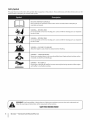 6
6
-
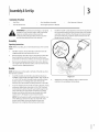 7
7
-
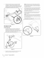 8
8
-
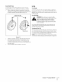 9
9
-
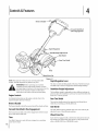 10
10
-
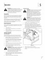 11
11
-
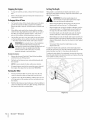 12
12
-
 13
13
-
 14
14
-
 15
15
-
 16
16
-
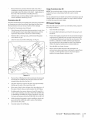 17
17
-
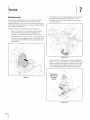 18
18
-
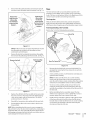 19
19
-
 20
20
-
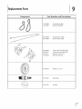 21
21
-
 22
22
-
 23
23
-
 24
24
-
 25
25
-
 26
26
-
 27
27
-
 28
28
-
 29
29
-
 30
30
-
 31
31
-
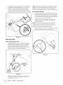 32
32
-
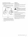 33
33
-
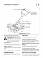 34
34
-
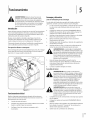 35
35
-
 36
36
-
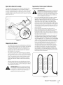 37
37
-
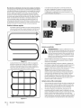 38
38
-
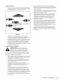 39
39
-
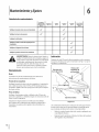 40
40
-
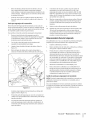 41
41
-
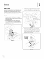 42
42
-
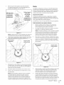 43
43
-
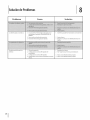 44
44
-
 45
45
-
 46
46
-
 47
47
-
 48
48


MTD 21AA40M1029 El manual del propietario
- Categoría
- Mini cultivadores
- Tipo
- El manual del propietario
- Este manual también es adecuado para
en otros idiomas
- English: MTD 21AA40M1029 Owner's manual
Artículos relacionados
Otros documentos
-
ACE Pro-Line CRT El manual del propietario
-
-
-
Cub Cadet RT-45 Manual de usuario
-
Troy-Bilt 21D64M1066 Manual de usuario
-
Troy-Bilt 21C65M1011 Manual de usuario
-
-
 Remington Power Tools 109312-01 Manual de usuario
-
Remington Garden Wizard 109312-01 El manual del propietario
-
