
SAFETY PRECAUTIONS:
WARNINGS:
• WARNING: HIGH VOLTAGE: Disconnect source of electrical power by
removing fuse or switching off circuit breakers.
• Do not use with solid state fans.
• Electrical wiring must meet all local and national electrical code
requirements.
• Electrical source and fan must be 115/120 volt, 60 Hz. Maximum fan
motor amps: 1.0. Maximum light watts: 300-incandescent only.
• Household electrical power can cause serious injury or death.
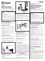
Note: The frequencies on your Receiver and Transmitter have been preset
at the factory. Before installing the Receiver, make sure the dip switches
on the Receiver are set to the same position on the Transmitter. (Fig. 1)
The dip switches on the Transmitter are located on one side of the control.
INSTALLATION INSTRUCTIONS:
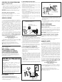
A. INSTALLING THE RECEIVER (FIG. 2)
1. Remove ceiling fan canopy from mounting bracket.
2. Disconnect existing wiring between ceiling fan and supply wires from
junction box.
B. CONNECTING THE RECEIVER
Using the wire nuts provided, make the electrical connections as follows:
1. Connect Green wire from fan to the Bare copper (ground) from junction
box.
2. Connect Black wire (AC IN L) from Receiver unit to the Black wire from
junction box.
3. Connect White wire (AC IN N) from Receiver unit to White wire from
junction box.
4. Connect White wire (TO MOTOR N) from Receiver unit to White wire
from fan.
5. Connect Black or Red wire (TO MOTOR L) from Receiver unit to Black or
Red wire from fan.
6. Connect Blue wire (FOR LIGHT) from Receiver unit to Blue wire from fan.
If other fan or supply wires are different color, consult or have a qualified
electrician do the installation.
7. After wires are connected, carefully tuck them into the junction box.
8. Lay the black antenna wire on top of Receiver unit, and insert into
mounting bracket.
9. Reinstall the canopy on to mounting bracket.
C. CONNECTING THE TRANSMITTER
1. Remove wall plate, disconnect and remove the toggle switch from
wall
junction box. Using the wire nuts provided, make the electrical
connections to the new Transmitter unit as shown in figure 2.
2. If your outlet box has a ground wire (green or bare copper), connect
the wall transmitter’s ground wire to it; otherwise connect the wall
transmitter’s ground wire directly to one of the screws from the
outlet box.
3. Carefully tuck wire connections inside wall switch box. Secure
Transmitter with the two screws (provided). Attach wall plate over
control unit with the 2 screws previously removed (FIG 3).
D. OPERATING THE TRANSMITTER
1. HI, MED and LOW buttons:
These three buttons are used to select the fan speed.
Press and release the button of the desired speed setting;
HI=Highest speed
MED=Medium speed
LOW=Lowest speed
2. “LIGHT” button: This button will turn the light on or off and will also control
the brightness setting. Press and release the button and the light will turn
on or off. Press and hold the button for the desired brightness. The light
CODE SWITCHES
INTERRUPTORES DE CÓDIGO
COMMUTATEURS DU TRANSMETTEUR
TRANSMITTER
TRANSMISOR
TRANSMETTEUR
FIG. 1
1 2 3 4
RECEIVER
RECEPTOR
RÉCEPTEUR
1 2 3 4
CODE SWITCHES
INTERRUPTORES DE CÓDIGO
COMMUTATEURS DU TRANSMETTEUR
OFF
ON
PRECAUCIONES DE SEGURIDAD:
ADVERTENCIAS:
• ADVERTENCIA: ALTA TENSIÓN: Desconecte el suministro eléctrico
quitando el fusible o apagando los cortacircuitos.
• No lo utilice con ventiladores de estado sólido.
• El cableado eléctrico debe cumplir con los requisitos de los códigos
locales y nacionales de electricidad.
• El voltaje y la frecuencia de la fuente de suministro eléctrico y del
ventilador deben ser: 115/120 voltios, 60 Hz. Amperaje máximo
del motor del ventilador: 1.0. Vataje máximo: 300, únicamente
incandescente.
• La energía eléctrica residencial puede causar lesiones graves o la
muerte.
NOTA: ANTES DE COMENZAR CON LA INSTALACIÓN DE SU NUEVO
CONTROL REMOTO, ASEGÚRESE DE QUE LA CONFIGURACIÓN DE
VELOCIDAD DEL VENTILADOR SEA LA MÁS ALTA.
EXPLICACIÓN PARA HACER LAS CONEXIONES ELÉCTRICAS:
A. INSTALACIÓN DEL RECEPTOR (FIG. 2)
1. Retire el dosel del ventilador de techo del soporte de montaje.
2. Desconecte el cableado existente entre el ventilador de techo y los cables
de alimentación de la caja de empalmes.
B. CONEXIÓN DEL RECEPTOR
Realice las conexiones eléctricas utilizando las tuercas para cables incluidas
siguiendo estas instrucciones:
1. Conecte el cable Verde del ventilador al cable de Cobre sin aislamiento
(cable de tierra) de la caja de empalmes.
2. Conecte el cable Negro (CA VIVO) del Receptor al cable Negro de la caja
de empalmes.
3. Conecte el cable Blanco (CA NEUTRO) del Receptor al cable Blanco de
la caja de empalmes.
4. Conecte el cable Blanco (AL MOTOR NEUTRO) del Receptor al cable
Blanco del ventilador.
5. Conecte el cable Negro o Rojo (AL MOTOR VIVO) del Receptor al cable
Negro o Rojo del ventilador.
6. Conecte el cable Azul (PARA LA LÁMPARA) del Receptor al cable Azul
del ventilador. Si otros cables del ventilador o de alimentación son de
diferente color, consulte o solicítele a un electricista certificado que
realice la instalación.
7. Después de conectar los cables, métalos con cuidado en la caja de
empalmes.
8. Coloque el cable negro de la antena sobre el Receptor e insértelo en el
soporte de montaje.
9. Vuelva a colocar el dosel en el soporte de montaje.
C. CONEXIÓN DEL TRANSMISOR
1. Quite la placa de pared, desconecte y saque el interruptor de palanca bid
reccional de la caja de empalmes de la pared. Realice las conexiones
eléctricas en el nuevo Transmisor utilizando las tuercas para cables
incluidas como se muestra en la Figura 2.
2. Si la caja de embutir tiene un cable de tierra (verde o cobre sin
aislamiento),
conéctelo al cable de tierra del transmisor de pared; de lo contrario,
conecte el cable de tierra del transmisor de pared directamente a uno de
los tornillos de la caja de embutir.
3. Introduzca con cuidado los cables conectados dentro de la caja de
distribución de la pared. Asegure el Transmisor con los dos tornillos
(incluidos). Fije la placa de pared sobre la unidad de control utilizando
los 2 tornillos que extrajo previamente (Fig. 3).
D. MODO DE EMPLEO DEL TRANSMISOR
1. Botones HI (ALTA), MED (INTERMEDIA) y LOW (BAJA):
Estos tres botones se utilizan para seleccionar la velocidad del ventilador.
Presione y suelte el botón de la velocidad deseada;
HI=Velocidad más alta
MED=Velocidad intermedia
LOW=Velocidad más baja
2. Botón “LIGHT” (LUZ): Este botón sirve para encender o apagar la luz y
además controla el nivel de luminosidad. Presione y suelte el botón y la
luz se encenderá o apagará. Presione y mantenga presionado este botón
hasta lograr el nivel de luminosidad deseado. Mientras se mantenga
presionado este botón, el grado de iluminación alternará continuamente
del nivel más tenue al de mayor luminosidad. La llave de luz dispone de
memoria automática, es decir, mantiene el mismo nivel de luminosidad
que cuando se apagó por última vez.
3. Botón “FAN OFF” (APAGAR VENTILADOR): Este botón apagará el
ventilador.
4. Esta unidad de control remoto está equipada con 16 combinaciones
de códigos para prevenir posibles interferencias con otras unidades
de control remoto, como por ejemplo, abrepuertas, alarmas de auto o
sistemas de seguridad. Si el ventilador o el juego de luces se enciende o
se apaga sin que usted utilice el control remoto, simplemente cambie el
código de combinación en el Transmisor y el Receptor.
5. Memoria Si apaga el ventilador o la luz mediante el control de pared, este
último memorizará y recuperará automáticamente las últimas configuraciones
de velocidad del ventilador y de nivel de luminosidad cuando los vuelva
a encender.
Remote Fan Wall Control
Model: UC-6750
WARNING! SHUT POWER OFF
AT FUSE OR CIRCUIT BREAKER.
Note: The frequencies on your Receiver and Transmitter have been preset
at the factory. Before installing the Receiver, make sure the dip switches on
the Receiver are set to the same position on the Transmitter. (Fig. 1) The dip
switches on the Transmitter are located on one side of the control.
77875
Westinghouse Lighting Corporation, Philadelphia, PA 19154-1099, U.S.A.
a Westinghouse Electric Corporation licensee • www.westinghouseceilingfans.com
and “Westinghouse are registered trademarks of Westinghouse Electric Corporation
© 2005 WESTINGHOUSE LIGHTING CORP.
will cycle continuously between bright and dim settings as long
as the button is held down. The light key has auto resume, it will stay at
the same brightness as the last time it was turned off.
3. “FAN OFF”: This button will turn the fan off.
4. This remote control unit is equipped with 16 code combinations, to pre
vent possible interference from other remote units such as garage door
openers, car alarm or security systems. If your fan or light kit go on and
off without using your remote control, simply change the combination
code in your Transmitter and Receiver.
5. Memory function
If you turn off fan or light by wall control, it will memorize and recover
automatically to last time’s fan speed and light brightness when turned
on the next time.
TROUBLESHOOTING GUIDE
PROBLEM: REMOTE FAILS TO OPERATE
• Make sure all connections on Receiver and Transmitter are done
correctly and that there are no loose wires or wire connections. Make
sure fan pull chain is set to the highest speed. Make sure code switches
on Receiver and Transmitter are set to the same code.
CAUTION: Ceiling Angle Shall Not Exceed 30 Degrees,
For Mounting Controller, Models UC-7067 or UC-7068.
WARNING! HOOK UP “IN SERIES” ONLY!
Do not connect to hot and common wire of electric circuit or switch will be
damaged. Refer to diagram below.
The installation of your remote control is now complete, restore power to
junction box.
LIMITED WARRANTY
The Westinghouse thermostat remote control for ceiling fans
offers a limited warranty of one year from the date of purchase to the original
owner against defects in material and workmanship. All spare parts are covered
for ninety days only. This warranty is in lieu of all other warranties expressed or
implied.
Westinghouse will repair or replace this thermostat remote control if it is
defective due to faulty materials or workmanship. This warranty does not cover
service charges, batteries, defects resulting from accidents, damages caused
through abuse or alterations or by affixing any attachment not provided with
the product, improper installation or maintenance, failure of supporting
devices not supplied as original mounting hardware, exposures to extremes
of heat or humidity, incorrect voltage, surges in current, unauthorized repair,
or failures caused by modifications of the product or the acts of third parties.
See manual for proper installation.
If a warranty claim is made in the first year, simply return the thermostat remote
control with a copy of the original sales receipt, freight prepaid to Westinghouse
Lighting Corporation, who, at its option, shall repair or replace the thermostat remote
control or refund the purchase price.
Please pack product correctly to eliminate
shipping damage.
Send all thermostat remote controls and inquiries to:
Westinghouse Lighting Corp.
12401 McNulty Rd., Philadelphia, PA 19154-1099
Attn: Customer Service
If you have any questions regarding the installation of this item or the
warranty coverage, please call our consumer line at
1-888-417-6222
and a
representative will assist you.
FIG. 2
RECEIVER
RECEPTOR
RÉCEPTEUR
ANTENNA
BLACK
NEGRO
NOIR
BLUE / AZUL / BLEU
BLACK / NEGRO / NOIR
WHITE / BLANCO / BLANC
GREEN / VERDE / VERT
BLUE / AZUL / BLEU
BLACK / NEGRO / NOIR
WHITE / BLANCO / BLANC
BLACK
NEGRO
NOIR
WHITE
BLANCO
BLANC
INPUT
AC 120V
GREEN TO GROUND
VERDE A TIERRA
VERT DE MISE À LA TERRE
Control remoto de pared para ventiladores
Modelo: UC-6750
¡ADVERTENCIA! DESCONECTE EL
SUMINISTRO ELÉCTRICO QUITANDO
EL FUSIBLE O APAGANDO EL
CORTACIRCUITO.
Nota: Las frecuencias del Receptor y el Transmisor han sido programadas
en fábrica. Antes de instalar el Receptor, asegúrese de que los conmutadores
DIP del Receptor se encuentren en la misma posición que los del Transmisor.
(Fig. 1) Los conmutadores DIP del Transmisor se encuentran a un costado
del control.
OFF
ON
GREEN TO GROUND
VERDE A TIERRA
VERT DE MISE À LA TERRE
6-32 x 3⁄4" SCREWS
TORNILLOS DE 6-32 x 3⁄4"
VIS 6-32 x 3⁄4"
6-32 x 1⁄4" SCREWS
TORNILLOS DE 6-32 x 1⁄4"
VIS 6-32 x 1⁄4"
BLACK
NEGRO
NOIR
FIG. 3
La página se está cargando...
Transcripción de documentos
FIG. 2 Control remoto de pared para ventiladores Modelo: UC-6750 INPUT AC 120V Remote Fan Wall Control Model: UC-6750 BLACK NEGRO NOIR WHITE BLANCO BLANC GREEN TO GROUND VERDE A TIERRA VERT DE MISE À LA TERRE WARNING! SHUT POWER OFF AT FUSE OR CIRCUIT BREAKER. BLUE / AZUL / BLEU BLACK / NEGRO / NOIR WHITE / BLANCO / BLANC ANTENNA Note: The frequencies on your Receiver and Transmitter have been preset at the factory. Before installing the Receiver, make sure the dip switches on the Receiver are set to the same position on the Transmitter. (Fig. 1) The dip switches on the Transmitter are located on one side of the control. BLACK NEGRO NOIR SAFETY PRECAUTIONS: BLUE / AZUL / BLEU BLACK / NEGRO / NOIR WHITE / BLANCO / BLANC GREEN / VERDE / VERT WARNINGS: • WARNING: HIGH VOLTAGE: Disconnect source of electrical power by removing fuse or switching off circuit breakers. • Do not use with solid state fans. • Electrical wiring must meet all local and national electrical code requirements. • Electrical source and fan must be 115/120 volt, 60 Hz. Maximum fan motor amps: 1.0. Maximum light watts: 300-incandescent only. • Household electrical power can cause serious injury or death. Note: The frequencies on your Receiver and Transmitter have been preset at the factory. Before installing the Receiver, make sure the dip switches on the Receiver are set to the same position on the Transmitter. (Fig. 1) The dip switches on the Transmitter are located on one side of the control. will cycle continuously between bright and dim settings as long as the button is held down. The light key has auto resume, it will stay at the same brightness as the last time it was turned off. 3. “FAN OFF”: This button will turn the fan off. 4. This remote control unit is equipped with 16 code combinations, to pre vent possible interference from other remote units such as garage door openers, car alarm or security systems. If your fan or light kit go on and off without using your remote control, simply change the combination code in your Transmitter and Receiver. 5. Memory function If you turn off fan or light by wall control, it will memorize and recover automatically to last time’s fan speed and light brightness when turned FIG. 3 BLACK NEGRO NOIR A. INSTALLING THE RECEIVER (FIG. 2) 1. Remove ceiling fan canopy from mounting bracket. 2. Disconnect existing wiring between ceiling fan and supply wires from junction box. 1. Remove wall plate, disconnect and remove the toggle switch from wall junction box. Using the wire nuts provided, make the electrical connections to the new Transmitter unit as shown in figure 2. 2. If your outlet box has a ground wire (green or bare copper), connect the wall transmitter’s ground wire to it; otherwise connect the wall transmitter’s ground wire directly to one of the screws from the outlet box. 3. Carefully tuck wire connections inside wall switch box. Secure Transmitter with the two screws (provided). Attach wall plate over control unit with the 2 screws previously removed (FIG 3). FIG. 1 CODE SWITCHES INTERRUPTORES DE CÓDIGO COMMUTATEURS DU TRANSMETTEUR 1 2 3 4 RECEIVER RECEPTOR RÉCEPTEUR OFF 1 2 3 4 TRANSMITTER TRANSMISOR TRANSMETTEUR ON D. OPERATING THE TRANSMITTER 1. HI, MED and LOW buttons: These three buttons are used to select the fan speed. Press and release the button of the desired speed setting; HI=Highest speed MED=Medium speed LOW=Lowest speed 2. “LIGHT” button: This button will turn the light on or off and will also control the brightness setting. Press and release the button and the light will turn on or off. Press and hold the button for the desired brightness. The light PRECAUCIONES DE SEGURIDAD: ADVERTENCIAS: • ADVERTENCIA: ALTA TENSIÓN: Desconecte el suministro eléctrico quitando el fusible o apagando los cortacircuitos. • No lo utilice con ventiladores de estado sólido. • El cableado eléctrico debe cumplir con los requisitos de los códigos locales y nacionales de electricidad. • El voltaje y la frecuencia de la fuente de suministro eléctrico y del ventilador deben ser: 115/120 voltios, 60 Hz. Amperaje máximo del motor del ventilador: 1.0. Vataje máximo: 300, únicamente incandescente. • La energía eléctrica residencial puede causar lesiones graves o la muerte. A. INSTALACIÓN DEL RECEPTOR (FIG. 2) 1. Retire el dosel del ventilador de techo del soporte de montaje. 2. Desconecte el cableado existente entre el ventilador de techo y los cables de alimentación de la caja de empalmes. OFF ON GREEN TO GROUND VERDE A TIERRA VERT DE MISE À LA TERRE 6-32 x 1⁄4" SCREWS TORNILLOS DE 6-32 x 1⁄4" 6-32 x 3⁄4" SCREWS VIS 6-32 x 1⁄4" TORNILLOS DE 6-32 x 3⁄4" VIS 6-32 x 3⁄4" on the next time. TROUBLESHOOTING GUIDE Problem: Remote Fails to Operate • Make sure all connections on Receiver and Transmitter are done correctly and that there are no loose wires or wire connections. Make sure fan pull chain is set to the highest speed. Make sure code switches on Receiver and Transmitter are set to the same code. CAUTION: Ceiling Angle Shall Not Exceed 30 Degrees, For Mounting Controller, Models UC-7067 or UC-7068. WARNING! HOOK UP “IN SERIES” ONLY! Do not connect to hot and common wire of electric circuit or switch will be damaged. Refer to diagram below. The installation of your remote control is now complete, restore power to junction box. LIMITED WARRANTY CODE SWITCHES INTERRUPTORES DE CÓDIGO COMMUTATEURS DU TRANSMETTEUR Nota: Las frecuencias del Receptor y el Transmisor han sido programadas en fábrica. Antes de instalar el Receptor, asegúrese de que los conmutadores DIP del Receptor se encuentren en la misma posición que los del Transmisor. (Fig. 1) Los conmutadores DIP del Transmisor se encuentran a un costado del control. EXPLICACIÓN PARA HACER LAS CONEXIONES ELÉCTRICAS: B. CONNECTING THE RECEIVER C. CONNECTING THE TRANSMITTER ¡ADVERTENCIA! DESCONECTE EL SUMINISTRO ELÉCTRICO QUITANDO EL FUSIBLE O APAGANDO EL CORTACIRCUITO. NOTA: ANTES DE COMENZAR CON LA INSTALACIÓN DE SU NUEVO CONTROL REMOTO, ASEGÚRESE DE QUE LA CONFIGURACIÓN DE VELOCIDAD DEL VENTILADOR SEA LA MÁS ALTA. INSTALLATION INSTRUCTIONS: Using the wire nuts provided, make the electrical connections as follows: 1. Connect Green wire from fan to the Bare copper (ground) from junction box. 2. Connect Black wire (AC IN L) from Receiver unit to the Black wire from junction box. 3. Connect White wire (AC IN N) from Receiver unit to White wire from junction box. 4. Connect White wire (TO MOTOR N) from Receiver unit to White wire from fan. 5. Connect Black or Red wire (TO MOTOR L) from Receiver unit to Black or Red wire from fan. 6. Connect Blue wire (FOR LIGHT) from Receiver unit to Blue wire from fan. If other fan or supply wires are different color, consult or have a qualified electrician do the installation. 7. After wires are connected, carefully tuck them into the junction box. 8. Lay the black antenna wire on top of Receiver unit, and insert into mounting bracket. 9. Reinstall the canopy on to mounting bracket. 77875 RECEIVER RECEPTOR RÉCEPTEUR The Westinghouse thermostat remote control for ceiling fans offers a limited warranty of one year from the date of purchase to the original owner against defects in material and workmanship. All spare parts are covered for ninety days only. This warranty is in lieu of all other warranties expressed or implied. Westinghouse will repair or replace this thermostat remote control if it is defective due to faulty materials or workmanship. This warranty does not cover service charges, batteries, defects resulting from accidents, damages caused through abuse or alterations or by affixing any attachment not provided with the product, improper installation or maintenance, failure of supporting devices not supplied as original mounting hardware, exposures to extremes of heat or humidity, incorrect voltage, surges in current, unauthorized repair, or failures caused by modifications of the product or the acts of third parties. See manual for proper installation. If a warranty claim is made in the first year, simply return the thermostat remote control with a copy of the original sales receipt, freight prepaid to Westinghouse Lighting Corporation, who, at its option, shall repair or replace the thermostat remote control or refund the purchase price. Please pack product correctly to eliminate shipping damage. Send all thermostat remote controls and inquiries to: Westinghouse Lighting Corp. 12401 McNulty Rd., Philadelphia, PA 19154-1099 Attn: Customer Service If you have any questions regarding the installation of this item or the warranty coverage, please call our consumer line at 1-888-417-6222 and a representative will assist you. Westinghouse Lighting Corporation, Philadelphia, PA 19154-1099, U.S.A. a Westinghouse Electric Corporation licensee • www.westinghouseceilingfans.com and “Westinghouse are registered trademarks of Westinghouse Electric Corporation © 2005 Westinghouse Lighting Corp. B. Conexión del Receptor Realice las conexiones eléctricas utilizando las tuercas para cables incluidas siguiendo estas instrucciones: 1. Conecte el cable Verde del ventilador al cable de Cobre sin aislamiento (cable de tierra) de la caja de empalmes. 2. Conecte el cable Negro (CA VIVO) del Receptor al cable Negro de la caja de empalmes. 3. Conecte el cable Blanco (CA NEUTRO) del Receptor al cable Blanco de la caja de empalmes. 4. Conecte el cable Blanco (AL MOTOR NEUTRO) del Receptor al cable Blanco del ventilador. 5. Conecte el cable Negro o Rojo (AL MOTOR VIVO) del Receptor al cable Negro o Rojo del ventilador. 6. Conecte el cable Azul (PARA LA LÁMPARA) del Receptor al cable Azul del ventilador. Si otros cables del ventilador o de alimentación son de diferente color, consulte o solicítele a un electricista certificado que realice la instalación. 7. Después de conectar los cables, métalos con cuidado en la caja de empalmes. 8. Coloque el cable negro de la antena sobre el Receptor e insértelo en el soporte de montaje. 9. Vuelva a colocar el dosel en el soporte de montaje. C. Conexión del Transmisor 1. Quite la placa de pared, desconecte y saque el interruptor de palanca bid reccional de la caja de empalmes de la pared. Realice las conexiones eléctricas en el nuevo Transmisor utilizando las tuercas para cables incluidas como se muestra en la Figura 2. 2. Si la caja de embutir tiene un cable de tierra (verde o cobre sin aislamiento), conéctelo al cable de tierra del transmisor de pared; de lo contrario, conecte el cable de tierra del transmisor de pared directamente a uno de los tornillos de la caja de embutir. 3. Introduzca con cuidado los cables conectados dentro de la caja de distribución de la pared. Asegure el Transmisor con los dos tornillos (incluidos). Fije la placa de pared sobre la unidad de control utilizando los 2 tornillos que extrajo previamente (Fig. 3). D. Modo de empleo del Transmisor 1. Botones HI (ALTA), MED (INTERMEDIA) y LOW (BAJA): Estos tres botones se utilizan para seleccionar la velocidad del ventilador. Presione y suelte el botón de la velocidad deseada; HI=Velocidad más alta MED=Velocidad intermedia LOW=Velocidad más baja 2. Botón “LIGHT” (LUZ): Este botón sirve para encender o apagar la luz y además controla el nivel de luminosidad. Presione y suelte el botón y la luz se encenderá o apagará. Presione y mantenga presionado este botón hasta lograr el nivel de luminosidad deseado. Mientras se mantenga presionado este botón, el grado de iluminación alternará continuamente del nivel más tenue al de mayor luminosidad. La llave de luz dispone de memoria automática, es decir, mantiene el mismo nivel de luminosidad que cuando se apagó por última vez. 3. Botón “FAN OFF” (APAGAR VENTILADOR): Este botón apagará el ventilador. 4. Esta unidad de control remoto está equipada con 16 combinaciones de códigos para prevenir posibles interferencias con otras unidades de control remoto, como por ejemplo, abrepuertas, alarmas de auto o sistemas de seguridad. Si el ventilador o el juego de luces se enciende o se apaga sin que usted utilice el control remoto, simplemente cambie el código de combinación en el Transmisor y el Receptor. 5. Memoria Si apaga el ventilador o la luz mediante el control de pared, este último memorizará y recuperará automáticamente las últimas configuraciones de velocidad del ventilador y de nivel de luminosidad cuando los vuelva a encender.-
 1
1
-
 2
2


en otros idiomas
- français: Westinghouse 7787500 Mode d'emploi
- English: Westinghouse 7787500 User guide
Artículos relacionados
-
Westinghouse 7787400 Manual de usuario
-
-
-
-
-
-
-

