Yamaha YHT-392: sumérgete en películas y música con este sistema de cine en casa de 5.1 canales.
Conecta fácilmente tus dispositivos con múltiples entradas, incluyendo HDMI, componentes, vídeo compuesto y audio digital. Disfruta del sonido envolvente de tus películas y música favoritos. La configuración es sencilla con la guía de conexión incluida, y los altavoces de alta calidad brindan un sonido claro y potente. El subwoofer agrega graves profundos y retumbantes para una experiencia de audio verdaderamente cinematográfica.

Transcripción de documentos
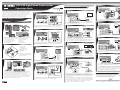
YHT-392 Digital Home Theater System Connection Guide English UCRLE © 2009 Yamaha Corporation All rights reserved. Printed in China WR88880 The Yamaha YHT-392 Digital Home Theater System includes everything you need to add great sound to your home theater. By following the steps in this Connection Guide, you’ll have your home theater set up in no time and be enjoying music and movies like never before. Part A explains how to connect the speakers and antennas. Part B explains how to connect various AV components. See the relevant owner’s manuals for full instructions and precautions. 5 Part B: AV Components AV Receiver Caution: Disconnect all components from AC outlets before proceeding. DVR/VCR ANTENNA OUT DOCK DTV/CBL DVR SURROUND DTV/CBL MONITOR OUT DVR OUT FM UNBAL. Y CD MULTI CH INPUT DVD CENTER DTV/CBL AUDIO DVR IN CD OUT MD/ OUT IN (PLAY) CD-R (REC) OUTPUT SUB WOOFR FRONT A SUBWOOFER TV SPEAKERS ANTENNA SURROUND DTV/CBL DVD OUT SURROUND DVD COAXIAL AV Receiver CENTER IN FRONT B HDMI COMPONENT VIDEO MONITOR OUT DVR DTV/CBL FRONT DTV/ CBL Connecting your TV DVD FRONT B AM GND VIDEO DVD IN DOCK CENTER HDMI MONITOR OUT PB Connecting the front speakers SPEAKERS DTV/CBL DVD COMPONENT VIDEO DVD PR DIGITAL INPUT OPTICAL 1 4 Connecting your DVR/VCR AM PR GND VIDEO DIGITAL INPUT PB AV Receiver DVD DTV/CBL DVD DTV/CBL MONITOR OUT DVR OUT IN R AUDIO L FM UNBAL. OPTICAL Y CD MULTI CH INPUT CENTER SURROUND FRONT DTV/ CBL AUDIO DVR MD/ OUT IN (PLAY) CD-R (REC) CD OUT IN VIDEO OUTPUT SUB WOOFR OUT DVD COAXIAL DVD DTV/CBL FRONT B CENTER SURROUND FRONT A SUBWOOFER SPEAKERS ANTENNA DTV/CBL DVD OUT HDMI COMPONENT VIDEO DOCK MONITOR OUT DVR AM PR Caution: Disconnect all components from AC outlets before proceeding. GND VIDEO DIGITAL INPUT PB DVD DTV/CBL DVD DTV/CBL MONITOR OUT DVR OUT IN FM UNBAL. OPTICAL CD Y MULTI CH INPUT FRONT DTV/ CBL CENTER SURROUND AUDIO DVR CD OUT IN MD/ OUT IN (PLAY) CD-R (REC) OUTPUT SUB WOOFR DVD COAXIAL FRONT A SUBWOOFER VIDEO Part A: Speakers and Antennas 1 Use AV pin cables (not included) to connect your DVR (digital video recorder) or VCR to the AV Receiver’s DVR IN/OUT jacks, as shown. Checking the package contents 1 2 6 8 To front right speaker (2) 9 To front left speaker (1) 6 Use a video pin cable (not included) to connect the AV Receiver’s MONITOR OUT jack to a composite video input on your TV, as shown. Connecting your CD player AV Receiver CD player ANTENNA OUT Connect the front speaker (1+2) cables to the AV Receiver. Be sure to connect the colored wire to the red positive (+) terminal, and connect the other wire to the black negative (–) terminal. 2 DOCK Connecting your DVD player DTV/CBL DVR SURROUND DTV/CBL DVD CENTER FRONT B HDMI COMPONENT VIDEO DVD SPEAKERS MONITOR OUT AM PR GND DIGITAL INPUT VIDEO PB DVD DTV/CBL MONITOR OUT DVR IN OUT FM UNBAL. OPTICAL Y CD MULTI CH INPUT FRONT DTV/ CBL SURROUND DVD CENTER DTV/CBL AUDIO DVR IN CD OUT MD/ OUT IN (PLAY) CD-R (REC) OUTPUT SUB WOOFR AV Receiver DVD player ANTENNA OUT DOCK DTV/CBL DVR FRONT A SUBWOOFER SPEAKERS SURROUND DTV/CBL DVD CENTER FRONT B HDMI COMPONENT VIDEO DVD DVD COAXIAL MONITOR OUT AM > 4 3 PR 5 7 GND DIGITAL INPUT Connecting the center and surround speakers VIDEO PB DVD DTV/CBL DVD DTV/CBL MONITOR OUT DVR IN OUT FM UNBAL. OPTICAL Y CD MULTI CH INPUT FRONT DTV/ CBL SURROUND CENTER AUDIO DVR IN CD OUTPUT MD/ OUT IN (PLAY) CD-R (REC) OUT SUB WOOFR DVD COAXIAL FRONT A SUBWOOFER AV Receiver SPEAKERS ANTENNA DVD DTV/CBL DVR CENTER SURROUND DTV/CBL DVD OUT FRONT B HDMI COMPONENT VIDEO DOCK MONITOR OUT AM PR GND VIDEO DIGITAL INPUT PB DVD DTV/CBL DVD DTV/CBL MONITOR OUT DVR OUT IN FM UNBAL. OPTICAL CD Y MULTI CH INPUT FRONT DTV/ CBL CENTER SURROUND AUDIO DVR CD OUT IN MD/ OUT IN (PLAY) CD-R (REC) OUTPUT SUB WOOFR DVD COAXIAL FRONT A SUBWOOFER Use an audio pin cable (not included) to connect your CD player to the AV Receiver’s CD jacks, as shown. 5 Unpack and check the package contents. The following items are necessary to complete this Connection Guide. See the owner’s manuals for a complete list of supplied items. 1+2 Front Speakers (NS-B380) 7 AV Receiver (HTR-6230) 3+4 Surround Speakers (NS-B280) 8 Speaker cable 5 Center Speaker (NS-C380) 9 Subwoofer cable 6 Subwoofer (NS-SW380) 0 FM and AM antennas 2 To surround right speaker (4) 7 • Use a video pin cable (not included) to connect your DVD player’s composite video output to the AV Receiver’s DVD VIDEO jack, as shown. • Use a coaxial digital audio cable (not included) to connect your DVD player’s coaxial digital audio output to the AV Receiver’s DVD DIGITAL INPUT jack, as shown. To center speaker (5) To surround left speaker (3) Connecting your MD/CD recorder AV Receiver MD/CD recorder ANTENNA OUT DOCK DTV/CBL DVD DTV/CBL DVR CENTER FRONT B HDMI COMPONENT VIDEO DVD SPEAKERS SURROUND MONITOR OUT AM PR GND DIGITAL INPUT VIDEO PB DVD DTV/CBL DVR IN OUT MONITOR OUT FM UNBAL. OPTICAL Y CD MULTI CH INPUT DTV/ CBL FRONT SURROUND CENTER DVD DTV/CBL AUDIO DVR IN CD OUT MD/ OUT IN (PLAY) CD-R (REC) OUTPUT SUB WOOFR Connect the center speaker (5) and surround speaker (3+4) cables to the AV Receiver. Be sure to connect the colored wire to the red positive (+) terminal, and connect the other wire to the black negative (–) terminal. Positioning the speakers 3 Connecting your satellite/cable set-top box AV Receiver OUT DTV/CBL DVR FRONT A SUBWOOFER SPEAKERS SURROUND DTV/CBL DVD CENTER FRONT B HDMI COMPONENT VIDEO DVD COAXIAL Satellite/cable set-top box ANTENNA DOCK DVD MONITOR OUT AM PR 2 1 6 5 4 3 1 Front left speaker 2 Front right speaker 3 Surround left speaker 4 Surround right speaker 5 Center speaker 6 Subwoofer 6 Connecting the subwoofer GND DIGITAL INPUT VIDEO PB DVD DTV/CBL MONITOR OUT DVR IN OUT FM UNBAL. OPTICAL Y CD MULTI CH INPUT FRONT DTV/ CBL SURROUND CENTER DVD DTV/CBL AUDIO DVR IN CD MD/ OUT IN (PLAY) CD-R (REC) OUT OUTPUT SUB WOOFR DVD COAXIAL FRONT A SUBWOOFER AV Receiver Subwoofer (6) SPEAKERS ANTENNA DVD DTV/CBL DVR SURROUND DTV/CBL DVD OUT CENTER FRONT B HDMI COMPONENT VIDEO DOCK MONITOR OUT AM PR GND VIDEO DIGITAL INPUT PB DVD MONITOR OUT DVR DTV/CBL OUT IN FM UNBAL. OPTICAL CD Y MULTI CH INPUT FRONT DTV/ CBL SURROUND DVD CENTER AUDIO DVR DTV/CBL CD OUT IN MD/ OUT IN (PLAY) CD-R (REC) Use audio pin cables (not included) to connect your MD/CD player to the AV Receiver’s MD/CD-R IN/OUT jacks, as shown. OUTPUT SUB WOOFR DVD COAXIAL FRONT A SUBWOOFER Position the speakers as shown. See the owner’s manuals for more information on installing the speakers. 8 Use an AV pin cable (not included) to connect your satellite/cable set-top box to the AV Receiver’s DTV/CBL jacks, as shown. Connecting your portable music player AV Receiver Portable music player VOLUME SPEAKERS EDIT PRESET/TUNING A/B/C/D/E l PRESET/TUNING BAND h MEMORY TUNING AUTO/MAN'L SCENE 1 3 4 Preparing the cables and speakers Use the included subwoofer cable to connect the Subwoofer’s INPUT jack to the AV Receiver’s SUBWOOFER OUTPUT jack. Connecting HDMI-capable components PHONES DTV/CBL DVR CENTER FRONT B VIDEO DVD DTV/CBL DVD DTV/CBL DVR OUT MONITOR OUT FM UNBAL. Y FRONT SURROUND CENTER AUDIO DVR IN OUT CD MD/ OUT IN (PLAY) CD-R (REC) OUTPUT SUB WOOFR VIDEO DVD SURROUND CENTER Use a 3.5 mm stereo mini plug cable (not included) to connect your portable music player to the AV Receiver’s PORTABLE jack (on the front panel), as shown. DVD player FRONT B HDMI MONITOR OUT AM PR If your AV Receiver has a DOCK jack (U.S.A. and Canada models), you can connect a Yamaha Universal Dock for iPod, such as the YDS-11, or a Yamaha Bluetooth Wireless Audio Receiver, such as the YBA-10 (both sold separately). See the AV Receiver’s Owner’s Manual for more information. GND VIDEO DIGITAL INPUT PB DVD DVR DTV/CBL OUT IN MONITOR OUT FM UNBAL. OPTICAL CD Surround speakers (3+4) Y MULTI CH INPUT DTV/ CBL FRONT SURROUND CENTER DVD AUDIO DVR DTV/CBL IN OUT CD MD/ OUT IN (PLAY) CD-R (REC) OUTPUT SUB WOOFR DVD COAXIAL SUBWOOFER FRONT A TV Front speakers (1+2) • Cut the included speaker cable to suitable lengths for the front, center, and surround speakers. You need to make five cables altogether. Remove about 10 mm (3/8 in.) of insulation from the end of each wire, and then twist the bare strands tightly. • Connect the speaker cables to the front speakers (1+2), surround speakers (3+4), and center speaker (5). Connect the colored wire to the red positive (+) terminal, and connect the other wire to the black negative (–) terminal. See the owner’s manuals for more information on connecting the speaker cables. PORTABLE FRONT A SUBWOOFER SPEAKERS ANTENNA DTV/CBL DVD OUT AUDIO COAXIAL AV Receiver DVR PORTABLE GND IN DTV/CBL AUDIO HDMI MULTI CH INPUT COMPONENT VIDEO VIDEO MONITOR OUT PB DVD VIDEO AUX NIGHT h AM CD DOCK INPUT l EFFECT SPEAKERS SURROUND DTV/CBL DVD COMPONENT VIDEO DVD PR DTV/ CBL Center speaker (5) 4 3 STRAIGHT h VIDEO AUX ANTENNA OUT DOCK DIGITAL INPUT Connecting the antennas 2 PROGRAM l SILENT CINEMA AV Receiver OPTICAL 7 TONE CONTROL STANDBY /ON AM antenna Almost Finished Satellite/cable set-top box FM antenna (FM antenna type depends on destination country.) Connect the AM loop antenna and indoor FM antenna to the AV Receiver, as shown. See the owner’s manuals for more information about connecting antennas. If your TV and DVD player or satellite/cable set-top box have HDMI jacks, you can connect them via the AV Receiver. Using HDMI cables (not included), connect the AV Receiver’s HDMI OUT jack to an HDMI input on your TV, and connect your DVD player and satellite/cable set-top box to the AV Receiver’s DVD and DTV/CBL HDMI jacks, respectively, as shown. Note: Audio signals received by the HDMI inputs will be output by the HDMI-capable TV’s speakers, not the speakers connected to the AV Receiver. To listen to an HDMI-capable component through the AV Receiver’s speakers, you must make an analog or digital audio connection in addition to the HDMI connection, and mute the sound on the TV. Time to enjoy your Yamaha home theater system! See the owner’s manuals for more information about HDMI. Now, relax and enjoy the great sound of your Yamaha home theater system. • • • • Connect the AV Receiver, Subwoofer, and your other AV components to suitable AC outlets. Turn on the AV Receiver first, then the Subwoofer and your other AV components. Install the batteries in the AV Receiver’s remote control. See the relevant owner’s manuals for full operating instructions.-
 1
1

Yamaha YHT-392: sumérgete en películas y música con este sistema de cine en casa de 5.1 canales.
Conecta fácilmente tus dispositivos con múltiples entradas, incluyendo HDMI, componentes, vídeo compuesto y audio digital. Disfruta del sonido envolvente de tus películas y música favoritos. La configuración es sencilla con la guía de conexión incluida, y los altavoces de alta calidad brindan un sonido claro y potente. El subwoofer agrega graves profundos y retumbantes para una experiencia de audio verdaderamente cinematográfica.
en otros idiomas
- italiano: Yamaha YHT-392 Manuale del proprietario
- English: Yamaha YHT-392 Owner's manual
- Deutsch: Yamaha YHT-392 Bedienungsanleitung
- русский: Yamaha YHT-392 Инструкция по применению
- Nederlands: Yamaha YHT-392 de handleiding
- português: Yamaha YHT-392 Manual do proprietário
- dansk: Yamaha YHT-392 Brugervejledning
- svenska: Yamaha YHT-392 Bruksanvisning
- Türkçe: Yamaha YHT-392 El kitabı
Artículos relacionados
-
Yamaha YHT-292 El manual del propietario
-
Yamaha YHT-299 Guía del usuario
-
Yamaha YHT-298 El manual del propietario
-
Yamaha YHT-199 El manual del propietario
-
-
Yamaha NS-P280 El manual del propietario
-
-
-
Yamaha RX-V363 - AV Receiver El manual del propietario
-
Yamaha RX-V365 El manual del propietario