
Instrucciones del módulo de alarma GSM AKO-52041
Instructions for the GSM AKO-52041 alarm module
1- Instalación del equipo
El equipo AKO-52041 puede instalarse de dos maneras, fijado sobre una pared con
ayuda de los soportes y tornillos que se incluyen o como equipo de sobremesa, sin
ninguna fijación especial.
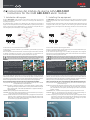
En la siguiente figura se pueden ver los detalles de los dos semicuerpos que forman el
equipo así como el esquema de los tornillos, embellecedores, soportes para la fijación en
pared, la posición del conector DB9 hembra (1) y el soporte para la tarjeta SIM (2) así
como las regletas para las entradas (3) y para la alimentación (4).
1- Installing the equipment
The AKO-52041 equipment can be installed in two ways: Either wall-mounted, with the
aid of the supports and screws that are included, or desktop-mounted with no specific
fastening.
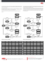
The following figure shows the details of the two half-bodies forming the equipment and
a diagram of the screws, trims, supports for wall-mounting, the position of the DB9
female connector (1) and support for the SIM card (2) and the input (3) and power supply
strips (4).
1
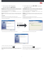
Terminals 9 and 10 are for a power supply of 230Vac.
Terminals 1 and 2 define Inputs 1 and 3, Terminal 4, Inputs 2 and 5 and Terminal 6 Input
3, and lastly, Terminals 7 and 8 define Input 4.
In the case that the power supply is not at 230Vac, the equipment can be supplied
through its built-in, rechargeable batteries which last for a mínimum of 7 hours from the
time the main power supply has been cut off.
Before handling the SIM card, the electrical supply of the GSM module must be
disconnected and the battery removed. Manipulating the SIM card without
observing these instructions could harm both the equipment and the card.
In the event of a power failure, an SMS is sent to the programmed number indicating this
problem, and in this way the user knows he has a mínimum of 7 hours within which to
remedy the fault before the equipment is rendered completely inoperative. When the
battery has run out, an SMS message is sent to the programmed number.
There are 8 LEDs on the cover of the equipment, with the following functions:
• IN1, IN2, IN3 and IN4: When any of these lights up, this means that an alarm signal is
present in that input.
• GPRS: This indicates the equipment coverage. If it lights up for a brief instant every 3
seconds, this means there is good coverage. If on the other hand, coverage is
poor, or the SIM card is not in place, the led will light up for about 1 second and
go off for 1 second.
• POWER: When on, it indicates that the equipment is supplied with 230Vac current.
• BATTERY: When on, this indicates that the equipment is fully supplied through its
built-in batteries and that no 230Vac current is available.
• STATUS: If everything is in order, the colour of the led will be green and go off for a brief
instant every 3 seconds. If on the other hand, the equipment is not ready (the
SIM is missing, the PIN is not disabled, there is no coverage or any other
problem arises) the led will turn red and blink rapidly.
E GB
5204H101 Ed.07
Los terminales 9 y 10 son los de alimentación a 230Vac.
Los terminales 1 y 2 definen la Entrada 1, 3 y 4 la Entrada 2, 5 y 6 la Entrada 3 y por último
7 y 8 la Entrada 4.
En el caso de que no hubiese alimentación a 230Vac el equipo se alimentaría a través de
las baterías recargables que incorpora y que le proporcionan una autonomía de un
mínimo de 7 horas desde el momento en que falla la alimentación principal.
Antes de manipular la tarjeta SIM, deberá desconectar la alimentación eléctrica y la
batería del modulo GSM. La manipulación de la tarjeta SIM no respetando estas
indicaciones puede causar daños tanto al equipo como a la propia tarjeta.
En el caso de pérdida de alimentación se enviará un mensaje SMS al número programado
indicando esta incidencia, de esta manera el usuario sabe que tiene un mínimo de 7 horas
para subsanar la avería antes de que el equipo quede totalmente inoperativo. Cuando la
batería se esté agotando también se enviará un mensaje SMS al número programado.
En la carátula del equipo tenemos 8 leds con la siguiente funcionalidad:
• IN1, IN2, IN3 e IN4: Cuando alguno de ellos está iluminado significa que en su entrada
correspondiente hay una señal de alarma.
• GPRS: Nos indica la cobertura del equipo. Si se enciende durante un instante cada 3
segundos significa que hay buena cobertura. Si no hay buena cobertura o la tarjeta
SIM no está colocada, el led estará aproximadamente 1 segundo encendido y 1
segundo apagado.
• POWER: Indica que el equipo está alimentado a 230Vac.
• BATTERY: Indica que el equipo está alimentado a través de las baterías que incorpora y
por tanto, que no hay alimentación a 230Vac.
• STATUS: Si todo está correcto el color del led será verde y se apagará un instante cada 3
segundos. Si por el contrario el equipo no está listo (falta SIM, el PIN no está
desactivado, no hay buena cobertura o cualquier otro problema), entonces el led
se iluminará en rojo y parpadeará rápidamente.
230V ~
50/60Hz
INPUT 1
INPUT 2
INPUT 3
INPUT 4
9 10
1 2 3 4
5 6 7 8
230V ~
50/60Hz
INPUT 1
INPUT 2
INPUT 3
INPUT 4
9 10
1 2 3 4
5 6 7 8
ATENCIÓN: Cuando coloque la tarjeta SIM en su equipo asegúrese de que ésta tenga el código PIN
desactivado, ya que de lo contrario el equipo no será operativo.
ATENCIÓN: Antes de configurar el equipo,
deberá conectarlo a la alimentación y conectar la
batería según muestra la imagen. Deberá dejar
que las baterías se carguen un mínimo de 5
horas antes de empezar a trabajar con el equipo.
Las baterías alcanzarán su máxima carga al cabo
de 48 horas.
WARNING:When putting the SIM card in place in the equipment, check that its PIN code has been
disabled, since otherwise, the equipment will not function.
WARNING: Before configure the equip-ment,
you will have to connect it to the Power Supply
and connect the battery as the image shows. You
will have to leave that the batteries load a
minimum of 5 hours before starting working
with the equipment. The batteries will reach full
charge after 48 hours.

2- Instrucciones del SW gestión
de terminales del AKO-52041
2- Instructions for the AKO-52041 terminals
management SW
The SW you are about to install in your PC will enable you to modify the configuration of
the AKO-52041 equipment, i.e., you can choose the type of contact for the alarm
signals, the telephone numbers to which you want to send the alarm messages, define
the persistency, confirmation and resolution time, the schedule, etc.
You can also control different pieces of AKO-52041 equipment through a single
application installed in your PC.
WARNING: It is very important that you read these instructions carefully, so that you
fully understand how the equipment works and can consequently obtain the maximum
performance from it.
Installation
Insert the CD into the drive and double click on the file setup.exe.
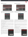
A window will pop up to inform you that the system is getting ready to install the SW and
then the following window will appear:
Haga clic sobre NEXT para
que el proceso continúe:
A continuación haga clic sobre Install, aparecerá la siguiente ventana: Then click on Install, and you will see the following window:
y haciendo clic sobre Finish, el proceso se habrá completado. Finally, click on Finish to conclude the process.
The following icon will appear on the desktop:
Double click on it to start executing the application. You can also do this through the
menu Start->Programmes->AKO->SOFTgsm and by clicking on SOFTgsm.
En su escritorio se habrá creado el siguiente icono:
Haciendo doble clic sobre él, empezará la ejecución de la aplicación. Igualmente puede
hacerlo a través del menú Inicio->Programas->AKO->SOFTgsm, y haciendo clic en
SOFTgsm.
2
El SW que usted va a instalar en su PC le permitirá modificar la configuración del equipo
AKO-52041, es decir, podrá elegir el tipo de contacto de sus señales de alarma, los
números de teléfono a los que enviará los mensajes de alarma, definir los tiempos de
persistencia, de confirmación y de resolución, el calendario, etc.
Asimismo, podrá gestionar diferentes equipos AKO-52041 a través de una única
aplicación instalada en su PC.
AVISO: Es muy importante que lea estas instrucciones con detenimiento para entender
perfectamente como funciona su equipo y conseguir así el máximo rendimiento del
mismo.
Instalación
Introduzca el CD en la lectora y haga doble clic sobre el fichero setup.exe.
Aparecerá una ventana que indica que el sistema se está preparando para instalar el SW y
a continuación la siguiente ventana:
Click on NEXT for the process
to continue:

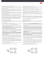
Description of the application
The first time you execute the programme, you will see the following window:
Descripción de la aplicación
La primera vez que ejecute el programa, aparecerá la siguiente ventana:
In Equipment data identify the equipment on which you are working at present and fill in
all the fields (Name, serial number and IMEI) and then select any of the calendars defined
previously (if any) or if not, create one (by clicking on the binoculars logo). If creating a
new calendar, the following window will pop up:
En Datos del equipo deberá identificar el equipo sobre el que está trabajando
actualmente, debe rellenar todos los campos (Nombre, número de serie e IMEI) y elegir
alguno de los calendarios definidos previamente, si hubiese, o sino crear uno (hacer clic
sobre el icono de los binoculares). Al crear un calendario nuevo le aparecerá la siguiente
ventana:
Press New and you will be asked what name you want to assign to your calendar. You can
then define the festive days (e.g., December 25, January 1, etc.) or mark all Saturdays and
Sundays as festive days. Similarly, you can define exceptions, that is, if you have marked
Saturdays as festive days, but for the purpose of controlling the alarms, you want
Saturday February 17 to be considered a working day, indicate this in the exceptions
chart.
After defining the calendar, click on Accept and then select it in the unfoldable Calendar
menu.
After filling in all the fields in Equipment Data and selecting the Calendar you want, go to
the menu Equipment and click on the option New, after which you will have defined the
configuration of this equipment and be able to recover it whenever you like for later
modifications.
Up to now, the alarms menu was disabled, but after creating your equipment, it is now
enabled and you can configure the alarms.
The AKO-52041 equipment is able to control 4 external alarms and send messages in
the event of a failure in the power supply of the equipment at 230Vac and if a failure is
detected in the internal battery.
All the configuration tabs for Inputs 1 to 4, Internal battery failure and Power failure are
the same, except for Input Type which does not appear in the last two.
The message you want the alarm receivers to
receive can be written in the SMS field (See
table of valid characters). Up to 5 telephone
numbers can be defined for working days and
the same number for festive days. To select the
telephone numbers, they must first of all have
been inserted in the Phone book. Click on the
binoculars to see the following screen:
Haga clic en Nuevo, le preguntará que nombre desea darle a su calendario. A continua-
ción podrá definir los días festivos (por ejemplo el 25 de diciembre, el 1 de Enero, etc), o
marcar todos los sábados o domingos como festivos. Asimismo podrá definir excepciones,
esto es, si usted ha marcado los sábados como festivos, pero le interesa que a efectos de
gestión de sus alarmas, el sábado 17 de Febrero sea considerado como laborable, deberá
indicarlo en el cuadro de excepciones.
Una vez haya definido su calendario haga clic sobre Aceptar y a continuación selecciónelo
en el desplegable del Calendario.
Cuando haya rellenado todos los campos de Datos del Equipo y elegido el Calendario que
desee, deberá ir al menú Equipo y hacer clic en la opción Nuevo, con lo cual, usted tendrá
definida la configuración de éste equipo y podrá recuperarlo cuando desee para
posteriores modificaciones.
Hasta este momento el menú de alarmas estaba deshabilitado, pero una vez creado, su
equipo estará activo y podrá configurar las alarmas.
El equipo AKO-52041 puede gestionar 4 alarmas externas y enviar mensajes si se
produce un fallo en la alimentación del equipo a 230Vac así como si se detecta un fallo en
la batería interna.
Todas las pestañas de configuración de las Entradas 1 a 4, Fallo batería interna y Fallo de
Alimentación son iguales a excepción del Tipo de Entrada que no aparece en estas dos
últimas.
En el campo del SMS se escribirá el mensaje que
queremos que reciban los receptores de la
alarma (Ver Tabla de caracteres válidos).
Podemos definir hasta 5 números de teléfono
para días laborables y otros tantos para días
festivos. Para seleccionar los números de
teléfono, previamente deberemos haberlos
introducido en el Listín telefónico.Haciendo clic
sobre los binoculares, nos aparecerá la siguiente
pantalla:
3

Enter the Names and Phones in the line marked with an *. They can be listed in
alphabetical order, by name or by telephone number.
As already explained above, Inputs 1 to 4 have a field called Input Type in which you
must choose between Normally open (NO) and Normally closed (NC)
An Input is defined as Normally open (NO) if the relay or switch connected to the
equipment input is open in a situation in which no alarm is enabled. If an alarm is
generated the relay or switch is closed causing the pertinent SMS to be sent.
An Input is defined as Normally closed (NC) if the relay or switch connected to the
equipment input is closed in a situation in which there is no alarm enabled. If an alarm is
generated the relay or switch opens, causing the pertinent SMS to be sent.
In all the alarms, it is possible to configure the Persistency time, Confirmation time and
Resolution time which will be described in the section entitled Message-sending
sequence.
After defining all the alarms, with their respective telephone numbers and associated
messages, this configuration must be sent to the equipment using the Rs232
communication for which we must connect the cable supplied with the equipment from
a PC with a serial port to the equipment port. Then go to the option “Equipment->Send
configuration” and the information will be sent to the module.
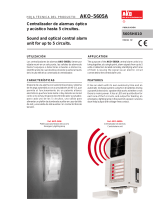
Message-sending sequence
When the opening or closing of any of the relays connected to the inputs during a
persistency time is detected, the alarm SMS is sent, in accordance with the following
cycle:
1. The alarm SMS is sent to the first pre-established phone number from the group
of working days or the group of festive days, depending on what the current day is. 2.
Then a positive response is awaited during a confirmation time with respect to the
alarm received by the phone number through an SMS sent to the number assigned to
the GSM Alarm Module.
The positive response received with respect to the alarm will be sent to
the phone number assigned to the AKO-52041 equipment in the form of
an SMS containing only the text OK, with no spaces, and in block capitals.
3. If, after the confirmation time has elapsed, no confirmation of the alarm receipt is
received from the first telephone number or the confirmation is negative (the person
responsible cannot come), the SMS alarm message is automatically sent again to the
second pre-established number and so on, by cycles, until it is sent to the fifth
telephone number.
Negative confirmation (i.e., an indication that the person responsible
cannot come) will be then sent to the telephone number assigned to the
AKO-52041 equipment, in the form of an SMS containing only the text NO
with no spaces, and in block capitals.
4. If before the confirmation time is up, the mobile has given a positive response to the
receipt of the alarm, the GSM alarm module will wait during a resolution time from
the receipt of the SMS giving the positive confirmation so that the problem causing
the alarm to be enabled can be solved. This will make it necessary for someone to
come to the facility and solve the problem.
5. If after this resolution time, the relay continues to be closed, the module will interpret
that either the person responsible has not come to the facility to solve the problem
that gave rise to the alarm, or that it is taking longer than expected to solve the
problem and it will thus again send an SMS confirming that an attempt is being made
to solve the problem or confirming that it is impossible to go to the facility.
6. If a positive confirmation is given, we are now at step 4, and if a negative confirmation
is given, an SMS is sent to the next telephone number.
7. The order in sending the messages in the cycle is always as follows:
Introduciremos los Nombres y teléfonos en la línea marcada con *. Podremos ordenarlos
alfabéticamente por Nombre o por número de teléfono.
Tal y como se ha explicado anteriormente, las Entradas 1 a 4 tienen un campo llamado
Tipo de Entrada en el que se deberá escoger entre Normalmente abierta (NA) y
Normalmente cerrada (NC).
Una entrada se define como Normalmente abierta (NA) cuando el relé o interruptor
conectado a la entrada del equipo se encuentra abierto en una situación en la que no hay
alarma activada. Cuando se produce la alarma el relé o interruptor se cierran provocándose
el envío del SMS correspondiente.
Una entrada se define como Normalmente cerrada (NC) cuando el relé o interruptor
conectado a la entrada del equipo se encuentra cerrado en una situación en la que no hay
alarma activada. Cuando se produce la alarma el relé o interruptor se abren provocándose
el envío del SMS correspondiente.
En todas las alarmas podemos configurar el Tiempo de persistencia, Tiempo de confirmación
y Tiempo de resolución que serán descritos en el apartado Secuencia de envío de mensajes.
Una vez hayamos definido todas las alarmas, con sus correspondientes números de teléfono
y mensajes asociados deberemos enviar esta configuración al equipo utilizando la
comunicación RS232 para lo cual deberemos conectar el cable que se suministra con el
equipo entre un PC con puerto serie y el puerto del equipo. A continuación iremos a la
opción “Equipos->Enviar configuración” y la información será transmitida al módulo.
Secuencia de envío de mensajes
Cuando se detecte el cierre o la apertura de alguno de los relés conectados a las entradas
durante un tiempo de persistencia se procederá al envío de los SMS de alarma
conforme al siguiente ciclo:
1. Se envía el SMS de alarma al primer teléfono prefijado del grupo de días laborables o
del grupo de días festivos, según el día en el que estemos.
2. A continuación se esperará durante un tiempo de confirmación la respuesta
positiva de alarma recibida por parte del teléfono mediante un SMS al número de
teléfono asignado al Módulo de Alarma GSM.
La respuesta positiva de alarma recibida se enviará al número de teléfono
asignado al equipo AKO-52041 y consistirá en un SMS que únicamente
contendrá el texto OK, sin espacios y en mayúsculas.
3. Si pasado este tiempo de confirmación el primer teléfono no ha confirmado la
recepción de la alarma o es una confirmación negativa (el responsable no puede
acudir) automáticamente se enviará otra vez el mensaje SMS de alarma al segundo
teléfono prefijado y así cíclicamente hasta el quinto teléfono.
La confirmación negativa, esto es, la indicación de que el responsable no
puede acudir, se enviará al número de teléfono asignado al equipo AKO-
52041 y consistirá en un SMS que únicamente contendrá el texto NO, sin
espacios y en mayúsculas.
4. Si antes de que pase el tiempo de confirmación el móvil ha respondido positivamente a
la recepción de la alarma, entonces el módulo de alarma GSM esperará un tiempo de
resolución a partir de la recepción del SMS de la confirmación positiva para que el
problema que originó la activación de la alarma quede solucionado. Esto obliga a que
alguien se persone en la instalación y resuelva el problema.
5. Si pasado este tiempo de resolución el relé sigue cerrado, el módulo interpretará que o
bien el responsable no ha acudido a la instalación a solucionar el problema que originó
la alarma o bien que le está llevando más tiempo del esperado solucionar el problema
con lo cual le volverá a enviar un SMS para que confirme que está intentando arreglar
el problema o bien que confirme que no puede llegar.
6. Si confirma positivamente estaremos en el paso 4, si confirma negativamente entonces
se envía un SMS al siguiente teléfono.
7. El orden del envío de los mensajes dentro del ciclo será siempre éste:
4
1
er
tel.
2
o
tel.
3
er
tel.
5
o
tel.
4
o
tel.
1
st
tel.
2
nd
tel.
3
rd
tel.
5
th
tel.
4
th
tel.

Nos reservamos el derecho de suministrar materiales que pudieran diferir levemente de los
descritos en nuestras Hojas Técnicas.Información actualizada en nuestra web: www.ako.com
We reserve the right to supply materials that might vary slightly to those described in our
Technical Sheets. Updated information is available on our website: www.ako.com
.
Av. Roquetes, 30-38 | 08812 Sant Pere de Ribes | Barcelona | España
Tel. (34) 938 142 700 | Fax (34) 938 934 054 | e-mail: [email protected] | www.ako.com
AKO ELECTROMECÀNICA, S.A.L.
355204101 REV.06 2011
If the confirmation time is assigned a value 0, the equipment will not wait for a message
of positive or negative confirmation and no more messages will be sent and the cycle will
be interrupted at the first telephone number.
Similarly if the resolution time is 0, the equipment will not wait for the problem causing
the alarm to go off to be solved and as soon as an affirmative response is received from
any telephone number before the confirmation time has elapsed, the cycle will be halted.
The algorithm, which is the same for both working and festive days, would be defined in
the following manner:
Si al tiempo de confirmación se le da el valor 0, el equipo no esperará ningún mensaje de
confirmación positivo ni negativo y no enviará más mensajes, quedando el ciclo interrum-
pido en el primer teléfono.
De la misma manera si el tiempo de resolución es 0, el equipo no esperará que se resuelva
el problema que originó la alarma y en cuanto algún teléfono le responda afirmativa-
mente antes del tiempo de confirmación, el ciclo se detendrá.
El algoritmo, que es el mismo para días laborables y festivos, definido de la siguiente
manera:
Table of valid charactersTabla de caracteres válidos
space
0
B
R
h
x
!
1
C
S
i
y
"
2
D
T
j
z
#
3
E
U
k
%
4
F
V
l
&
5
G
W
m
'
6
H
X
n
(
7
I
Y
o
)
8
J
Z
p
*
9
K
a
q
+
:
L
b
r
,
;
M
c
s
-
<
N
d
t
.
=
O
e
u
/
>
P
f
v
?
A
Q
g
w
space
0
B
R
h
x
!
1
C
S
i
y
"
2
D
T
j
z
#
3
E
U
k
%
4
F
V
l
&
5
G
W
m
'
6
H
X
n
(
7
I
Y
o
)
8
J
Z
p
*
9
K
a
q
+
:
L
b
r
,
;
M
c
s
-
<
N
d
t
.
=
O
e
u
/
>
P
f
v
?
A
Q
g
w
Alarm
is triggered
SMS send to
1
st
telephone
SMS resent to
1
st
telephone
SMS send to
2
nd
telephone
SMS send to
3
rd
telephone
SMS send to
5
th
telephone
SMS resent to
2
nd
telephone
SMS resent to
5
th
telephone
Problem
solved before
resolution
time?
Positive
response before
confirmation
time?
End
YES
YES
NO
YES
NO
NO
NO
NO
NO
NO
YES
YES
YES
YES
YES
YES
NO
NO
Positive
response before
confirmation
time?
Positive
response before
confirmation
time?
Positive
response before
confirmation
time?
Positive
response before
confirmation
time?
Positive
response before
confirmation
time?
Problem
solved before
resolution
time?
Problem
solved before
resolution
time?
Salta
Alarma
Envío SMS
1
er
teléfono
Reenvío SMS
1
er
teléfono
Envío SMS
2
o
teléfono
Envío SMS
3
er
teléfono
Envío SMS
5
o
teléfono
Reenvío SMS
2
o
teléfono
Reenvío SMS
5
o
teléfono
¿Problema
solucionado
antes de t.
resolución?
¿Problema
solucionado
antes de t.
resolución?
¿Respuesta
positiva antes
de t. confir-
mación?
¿Respuesta
positiva antes
de t. confir-
mación?
¿Respuesta
positiva antes
de t. confir-
mación?
¿Respuesta
positiva antes
de t. confir-
mación?
¿Respuesta
positiva antes
de t. confir-
mación?
Fin
SI
SI
NO
SI
NO
NO
NO
NO
NO
NO
SI
SI
SI
SI
SI
SI
NO
NO
¿Problema
solucionado
antes de t.
resolución?
¿Respuesta
positiva antes
de t. confir-
mación?
-
 1
1
-
 2
2
-
 3
3
-
 4
4
-
 5
5


AKO GSM AKO-52041 alarm module Instrucciones de operación
- Tipo
- Instrucciones de operación
- Este manual también es adecuado para
en otros idiomas
Otros documentos
-
ACI Farfisa PL11G El manual del propietario
-
Extraflame GSM Module El manual del propietario
-
LG GU285G.ACROSV Manual de usuario
-
LG GS290.APNNLU Manual de usuario
-
-
LG U8150.TLFSV Manual de usuario
-
LG Série GM360.ACHNBK Manual de usuario
-
LG GS500G.AEPTBK Manual de usuario
-
LG Electronics U8500 Manual de usuario
-
 AKO Electronica AKO-5605A Manual de usuario
