Rockford Fosgate M2 ELEMENT READY M2D2-10S Manual de usuario
- Categoría
- Subwoofers
- Tipo
- Manual de usuario
Este manual también es adecuado para
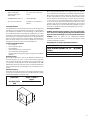
El Rockford Fosgate M2 ELEMENT READY M2D2-10S es un subwoofer resistente a la intemperie que ofrece un sonido de alta calidad en cualquier entorno. Con una potencia de pico de 1600 vatios y 400 vatios RMS a 2 ohmios, este subwoofer puede producir graves potentes y profundos. Su impedancia nominal de 2 ohmios lo hace compatible con una variedad de sistemas de audio. El M2D2-10S también cuenta con una respuesta de frecuencia de 20-750 Hz y una sensibilidad de 85,1 dB, lo que garantiza una reproducción de audio clara y precisa.
El Rockford Fosgate M2 ELEMENT READY M2D2-10S es un subwoofer resistente a la intemperie que ofrece un sonido de alta calidad en cualquier entorno. Con una potencia de pico de 1600 vatios y 400 vatios RMS a 2 ohmios, este subwoofer puede producir graves potentes y profundos. Su impedancia nominal de 2 ohmios lo hace compatible con una variedad de sistemas de audio. El M2D2-10S también cuenta con una respuesta de frecuencia de 20-750 Hz y una sensibilidad de 85,1 dB, lo que garantiza una reproducción de audio clara y precisa.


Transcripción de documentos
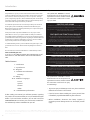
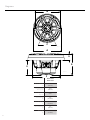
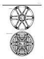
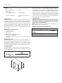
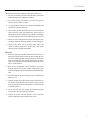
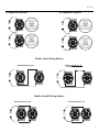
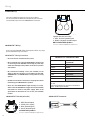
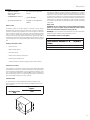
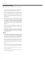
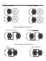
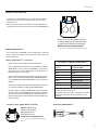
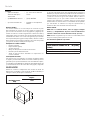
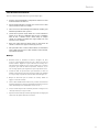
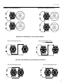
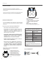
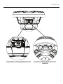
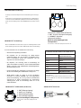
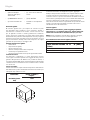
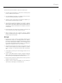
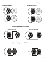
02122020 1230-74356-01-A Printed In China rockfordfosgate.com 600 South Rockford Drive • Tempe, Arizona 85281 United States Direct: (480) 967-3565 • Toll Free: (800) 669-9899 Installation assistance available at: M2D4-10S M2D4-10SB M2D2-10S M2D2-10SB ELEMENT READY™ SUBWOOFERS Installation & Operation Introduction Safety Dear Customer, Congratulations on your purchase of the world’s finest brand of audio products. At Rockford Fosgate we are fanatics about musical reproduction at its best, and we are pleased you chose our product. Through years of engineering expertise, hand craftsmanship and critical testing procedures, we have created a wide range of products that reproduce music with all the clarity and richness you deserve. For maximum performance we recommend you have your new Rockford Fosgate product installed by an Authorized Rockford Fosgate Dealer. Please read your warranty and retain your receipt and original carton for possible future use. Great product and competent installations are only a piece of the puzzle when it comes to your system. Make sure that your installer is using 100% authentic installation accessories from Rockford Fosgate in your installation. Rockford Fosgate has everything from RCA cables and speaker wire to power wire and battery connectors. Insist on it! After all, your new system deserves nothing but the best. To add the finishing touch to your new Rockford Fosgate image, order your Rockford accessories, which include everything from T-shirts to hats. This symbol with “WARNING” is intended to alert the user to the presence of important instructions. Failure to heed the instructions could result in severe injury or death. PRACTICE SAFE SOUND Continuous exposure to sound pressure levels over 100dB may cause permanent hearing loss. High powered auto sound systems may produce sound pressure levels well over 130dB. Use common sense and practice safe sound. PRATIQUEZ UNE ÉCOUTE SANS RISQUES Une exposition continue à des niveaux de pression acoustique upérieurs à 100 dB peut causer une perte d’acuité auditive permanente. Les systèmes audio de forte puissance pour auto peuvent produire des niveaux de pression acoustique bien au-delà de 130 dB. Faites preuve de bon sens et pratiquez une écoute sans risques PRACTIQUE EL SONIDO SEGURO Visit our web site for the latest information on all Rockford products; El contacto continuo con niveles de presión de sonido superiores a 100 dB puede causar la pérdida permanente de la audición. Los sistemas de sonido de alta potencia para automóviles pueden producir niveles de presión de sonido superiores a los 130 dB. Aplique el sentido común y practique el sonido seguro. Table of Content Fortgesetzte Geräuschdruckpegel von über 100 dB können beim Menschen zu permanentem Hörverlust führen. Leistungsstarke Autosoundsysteme können Geräuschdruckpegel erzeugen, die weit über 130 dB liegen. Bitte wenden Sie gesunden Menschenverstand an und praktizieren Sie sicheren Sound. www.rockfordfosgate.com or, in the U.S. call 1-800-669-9899 or FAX 1-800-398-3985. For all other countries, call +001-480-967-3565 or FAX +001-480-9663983. 2 Introduction 3 Specifications 4-5 Diagrams 6 Installation Considerations Mounting 7-9 Wiring 10-25 Additional Languages French Spanish German Italian 28 Limited Warranty Information If, after reading your manual, you still have questions regarding this product, we recommend that you see your Rockford Fosgate dealer. If you need further assistance, you can call us direct at 1-800-669-9899. Be sure to have your serial number, model number and date of purchase available when you call. PRAKTIZIEREN SIE SICHEREN SOUND OSSERVATE LE REGOLE DEL SUONO SENZA PERICOLI La costante esposizione a livelli di pressione acustica al di sopra dei 100dB possono causare la perdita permanente dell’udito. I sistemi audio ad alta potenza possono produrre livelli di pressione acustica ben superiori ai 130dB. Si consiglia il buon senso e l’osservanza delle regole del suono senza pericoli This symbol with “CAUTION” is intended to alert the user to the presence of important instructions. Failure to heed the instructions could result in injury or unit damage. • To prevent injury and damage to the unit, please read and follow the instructions in this manual. • If you feel unsure about installing this system yourself, have it installed by a qualified Rockford Fosgate technician. • Before installation, disconnect the battery negative (-) terminal to prevent damage to the unit, fire and/or possible injury. ©2019 RockfordCorporation. All Rights Reserved. ROCKFORD FOSGATE, PUNCH® and associated logos where applicable are registered trademarks of Rockford Corporation in the United States and/or other countries. All other trademarks are the property of their respective owners. Specifications subject to change without notice. 2 Specifications Model Nominal Diameter Description Nominal Impedance (Ohms) Frequency Response (Hz) Voice Coil Diameter - inch (mm) Power Handling - Watts (RMS/Peak) Fs - Free Air Resonance (Hz) Qts M2D2-10S/SB M2D4-10S/SB 10” (254mm) Subwoofer 2 or 4 Ω DVC 20-750 1.95” (2-Layer) (49.5mm) 400/1600 28 0.82 Vas - cu. ft. (Liter) 1.33 (36.8L) Displacment -cu. fl. (Liter) 0.13 (1.74L) Sensitivity (2.83V/1M) 85.1dB Xmax - inch (mm) Grille/Trim Ring LED Current Draw Recommended Fused Rating For LED’s (not included) LED Voltage Range 0.47” (12mm) YES 0.25 Amps 1 Amp 9-16 Volts * All measurements taken with voice coils wired in series VERIFIED WITH KLIPPEL To adorn the ‘Verified with Klippel’ mark, the qualifying company’s loudspeaker engineering personnel must be trained and certified by Klippel prior to using the three separate Klippel systems to design, develop and test. Rockford Fosgate has made the investment in Klippel to deliver the best possible speakers and subwoofers to their customers. 3 Diagrams B E F C illus.-1.1 B A G D E illus.-2.1 F Model C A 4 M2D2-10I/IB M2D4-10I/IB Overall Diameter (A) 11” (279mm) Screw Mounting Diameter (B) 10.16” (258mm) Mounting Screw Angle (C) 6X60° Overall Height (D) 6.11” (155.2mm) Mounting Depth (E) 4.12” (104.6mm) Cut-out Diameter (F) 8.9” (225mm) Grill Height (G) 2” (50.8mm) Diagrams Sport Grill Stainless Steel Grill 5 Installation Contents • (1)Element Ready™ Subwoofer with Sport/ Stainless Grill • (6) Socket Head Stainless Screws • (1) COLOR OPTIX™ Harness • (1) 1/8” Drill Bit • (1) Socket head driver bit • Installation and Operation Manual Sealed Enclosures Sealed enclosures are the simplest to build. The most important part of building a sealed enclosure is to make sure that the enclosure is airtight. Using glue and some type of sealant on all seams will ensure solid construction and prevent air leaks. The box volume will directly impact the performance of the speaker. Larger enclosures will provide flatter response and deeper bass where smaller boxes will provide a bump in the response curve and generally higher output for greater SPL. Advantages of sealed enclosures: • Small enclosures • Linear (Flat) response • No port noise • High power handling at all frequencies • Excellent for sound quality • Extended low frequency output when compared to vented enclosures Building an Enclosure To work properly, the walls of the enclosure must be rigid and not flex when subjected to the high pressures generated by the speaker’s operation. For optimum performance, we recommend using 3/4” MDF (Medium Density Fiberboard) and internal bracing. The enclosure should be glued together and secured with nails or screws. Calculating Volume Calculating volume is merely a matter of measuring the dimensions in inches and using the formula: H x W x D divided by 1728 (cubic feet). See block below. Box Volume Height” x Width” x Depth” Divided by (cubic feet) 1728 H W D 6 If two facing sides are of uneven length, add them together and divide by two to take the average. Using this number will give you the volume without the necessity of calculating the box in sections and adding the sections together. The thickness of the baffle material reduces the internal volume so this must be subtracted from the outside dimensions to determine the internal volume. The speaker itself also reduces the internal volume. The amount of air displaced by each model is listed on the specification sheet and should also be subtracted from the gross volume calculation. Sealed Enclosure NOTE: Vb is the internal volume, before any speaker and/or port displacement is added. All external dimensions were based on the use of 3/4” (1.90cm) materials. NOTE: When using enclosures other than recommended, call Technical Support for correct application. Optimum Sealed Enclosure Recommendation Sealed Enclosures Total Internal Volume cu. ft. (Liter) 10” .5 (14L) Woofer Displacement cu. ft. (Liter) 0.1 (2.83) Vb - Net Internal Volume cu. ft. (Liter) 1.0 (28.32) Installation Installation Considerations Before beginning any installation, follow these simple rules: 1. Be sure to carefully read and understand the instructions before attempting to install these speakers. 2. For easier assembly, we suggest you run all wires prior to mounting your speakers in place. 3. Use high quality connectors for a reliable installation and to minimize signal or power loss. 4. Think before you drill! Be careful not to cut or drill into gas tanks, fuel lines, brake or hydraulic lines, vacuum lines or electrical wiring when working on any vehicle. If installation in a boat, take care not to cut or drill through the main hull. 5. Never run wires underneath the vehicle. Running the wires inside the vehicle or hull area provides the best protection. 6. Avoid running wires over or through sharp edges. Use rubber or plastic grommets to protect any wires routed through metal, especially the firewall. Mounting 1. Determine where the speakers will be mounted. Ensure an area large enough for the speaker to mount evenly. Be sure that the mounting location is deep enough for the speaker to fit; if mounting in a door, operate all functions (windows, locks, etc.) through their entire operating range to ensure there is no obstruction. 2. Refer to the specification chart to determine the proper diameter hole to cut for your speaker model. Cutting and mounting templates can be found at www.rockfordfosgate. com. 3. Mark the locations for the mounting screws. Drill the holes with a 1/8” bit. 4. Feed the speaker wires through the cutout and connect to the speaker terminals. Be sure to observe proper polarity when connecting the wires. The speaker’s positive terminal is indicated with a “+”. 5. Fit the trim ring over the speaker and mount into place using the four (4) screws that are provided. 6. Tighten the screws until the speaker is snug in place to prevent rattling. Do not over tighten the screws. 7 Wiring illus.-4.1 SPEAKER TERMINAL SWITCH 8 SPEAKER & COLOR OPTIX™ TERMINALS 2 4Ω D4 Impedance Options Wiring D2 Impedance Options 8 2Ω 4Ω 2 1Ω 4Ω 8 8Ω 1 4 4Ω 4Ω 4Ω 2 2Ω Woofer Series Wiring Options 4Ω D4 with 1 Switch on 2Ω 1Ω D2 with Switch on 1 Ω 8 4Ω 2Ω 4Ω 2Ω 4 4Ω 1Ω 1 Woofer Parallel Wiring Options D4 with Switch on 8 Ω 4Ω 4Ω 1Ω 2Ω D2 with Switch on 4 Ω 4 2Ω 2Ω 1 9 2Ω Wiring SPEAKER Wiring There are (2) different options for wiring your speakers. You can also utilize the DEUTSCH™/Amphenol style connector (not included) input next to the COLOR OPTIX™ connector. 1 2 illus.-4.3 Speaker Pin Out (wire side) 1 - RED - Positive Speaker Input 2 - BLACK - Negative Speaker Input NOT included with speakers Connector is DEUTSCH™/Amphenol style DT06-2S COLOR OPTIX™ Wiring If not using the PMX-RGB, follow the diagrams below for proper pin out and hard wiring instructions. COLOR OPTIX™ Wiring Precautions COLOR OPTIX™ WIRING OPTIONS • Do not connect to 24 Volt electrical systems • We recommend only using the COLOR OPTIX™ wiring chart or connecting to the PMX-RGB. Connecting any other way could cause damage to the speakers or the device you have connected to. • We recommend installing a fuse (not included) on the Yellow 12 Volt wire whenever you are NOT using the PMXCOLOR OPTIX™. See COLOR OPTIX™ wiring chart for wiring options. • Rockford recommends a minimum of 20 gauge wire when hard wiring your COLOR OPTIX™ speakers. • Never wire the COLOR OPTIX™ lights directly to 12 volts. Utilize either the PMX-RGB or a toggle switch (not included) connected to a fused 12 volt power supply. Refer to the specification to determine the size of fuse (not included) needed COLOR OPTIX™ Pin Out (wire side) 1 2 3 4 1 - RED (Ground Input) 2 - Yellow (12V + Input) 3 - Blue (Ground Input) 4 - Green (Ground Input) Included with speakers illus.-4.1 10 Connector is DEUTSCH™/Amphenol style DT06-4S LED OUTPUT COLOR CONNECT THIS COLOR WIRE TO GROUND RED RED GREEN GREEN BLUE BLUE YELLOW RED & GREEN PINK RED & BLUE AQUA GREEN & BLUE WHITE RED, GREEN & BLUE Connect colored wires on right to make output color on left. Connect all Yellow wires together to switched 12 Volts. See Wiring Precautions. COLOR OPTIX™ Connector Included illus.-4.2 Enceintes Contents • (1)Element Ready™ Subwoofer with Sport/ Stainless Grill • (6) Socket Head Stainless Screws • (1) COLOR OPTIX™ Harness • (1) 1/8” Drill Bit • (1) Socket head driver bit • Installation and Operation Manual Si deux côtés opposés sont de longueur inégale, ajoutez-les ensemble et divisez-les par deux pour prendre la moyenne. L’utilisation de ce numéro vous donnera le volume sans avoir besoin de calculer la boîte en sections et d’ajouter les sections ensemble. L’épaisseur du matériau du déflecteur réduit le volume interne, il faut donc le soustraire des dimensions extérieures pour déterminer le volume interne. Le haut-parleur lui-même réduit également le volume interne. La quantité d’air déplacée par chaque modèle est indiquée sur la feuille de spécifications et doit également être soustraite du calcul du volume brut. Boîtier scellé Boîtiers scellés Les boîtiers scellés sont les plus simples à construire. La partie la plus importante de la construction d’une enceinte scellée consiste à s’assurer que l’enceinte est étanche à l’air. L’utilisation de colle et d’un type de scellant sur toutes les coutures assurera une construction solide et empêchera les fuites d’air. Le volume de la boîte aura un impact direct sur les performances de l’enceinte. Des enceintes plus grandes fourniront une réponse plus plate et des basses plus profondes où les petites boîtes fourniront une bosse dans la courbe de réponse et une sortie généralement plus élevée pour un plus grand SPL. Avantages des boîtiers scellés: • Petites enceintes • Réponse linéaire (plate) • Pas de bruit de port • Haute puissance à toutes les fréquences • Excellent pour la qualité sonore • Sortie basse fréquence étendue par rapport aux enceintes ventilées REMARQUE: Vb est le volume interne, avant tout déplacement de hautparleur et / ou port est ajouté. Toutes les dimensions externes étaient basées sur l’utilisation de matériaux de 3/4 po (1,90 cm). REMARQUE: Lorsque vous utilisez des boîtiers autres que ceux recommandés, appelez le support technique pour une application correcte. Recommandation de boîtier scellé optimal Sealed Enclosures Total Internal Volume cu. ft. (Liter) 10” .5 (14L) Woofer Displacement cu. ft. (Liter) 0.1 (2.83) Vb - Net Internal Volume cu. ft. (Liter) 1.0 (28.32) Construire une enceinte Pour fonctionner correctement, les parois de l’enceinte doivent être rigides et non flexibles lorsqu’elles sont soumises aux hautes pressions générées par le fonctionnement du haut-parleur. Pour des performances optimales, nous vous recommandons d’utiliser des panneaux MDF de 3/4 po (panneaux de fibres à densité moyenne) et des contreventements internes. Le boîtier doit être collé ensemble et fixé avec des clous ou des vis. Calcul du volume Le calcul du volume consiste simplement à mesurer les dimensions en pouces et à utiliser la formule: H x L x P divisée par 1728 (pieds cubes). Voir bloc ci-dessous. Box Volume Height” x Width” x Depth” Divided by (cubic feet) 1728 H W D 11 Enceintes Considérations d’installation Avant de commencer une installation, suivez ces règles simples: 1. Assurez-vous de lire attentivement et de comprendre les instructions avant d’essayer d’installer ces enceintes. 2. Pour un montage plus facile, nous vous suggérons de faire passer tous les fils avant de monter vos enceintes en place. 3. Utilisez des connecteurs de haute qualité pour une installation fiable et pour minimiser la perte de signal ou d’alimentation. 4. Réfléchissez avant de percer! Faites attention de ne pas couper ou percer dans les réservoirs de gaz, les conduites de carburant, les conduites de frein ou hydrauliques, les conduites de vide ou le câblage électrique lorsque vous travaillez sur un véhicule. En cas d’installation dans un bateau, veillez à ne pas couper ou percer la coque principale. 5. Ne faites jamais passer des câbles sous le véhicule. Faire passer les fils à l’intérieur du véhicule ou de la coque offre la meilleure protection. 6. Évitez de faire passer des fils sur ou à travers des arêtes vives. Utilisez des œillets en caoutchouc ou en plastique pour protéger tous les fils acheminés à travers le métal, en particulier le pare-feu. Montage 12 1. Déterminez où les enceintes seront montées. Assurez-vous que la surface de l’enceinte est suffisamment large pour être montée de manière uniforme. Assurez-vous que l’emplacement de montage est suffisamment profond pour que l’enceinte s’adapte; en cas de montage dans une porte, utilisez toutes les fonctions (fenêtres, serrures, etc.) sur toute leur plage de fonctionnement pour vous assurer qu’il n’y a pas d’obstruction. 2. Reportez-vous au tableau des spécifications pour déterminer le trou de diamètre approprié à couper pour votre modèle d’enceinte. Les gabarits de coupe et de montage sont disponibles sur www.rockfordfosgate.com. 3. Marquez les emplacements des vis de montage. Percez les trous avec un foret de 1/8 ”. 4. Faites passer les fils d’enceinte à travers la découpe et connectez-les aux bornes d’enceinte. Veillez à respecter la bonne polarité lors de la connexion des fils. La borne positive du haut-parleur est indiquée par un «+». 5. Placez l’anneau de garniture sur le haut-parleur et montez-le en place à l’aide des quatre (4) vis fournies. 6. Serrez les vis jusqu’à ce que le haut-parleur soit bien en place pour éviter les vibrations. Ne serrez pas trop les vis. Câblage illus.-3.1 COMMUTATEUR DE BORNE DE HAUT-PARLEUR BORNES DE HAUT-PARLEUR ET COLOR OPTIX™ 13 2 4Ω Câblage D4 Options d'impédance D2 Options d'impédance 8 2Ω 4Ω 2 1Ω 4Ω 8 8Ω 1 4 4Ω 4Ω 4Ω 2 2Ω Options de câblage en série de woofer 4Ω D4 avec commutateur sur 2Ω 1 1Ω D2 avec commutateur sur 1Ω 8 4Ω 2Ω 4Ω 2Ω 4 4Ω 1Ω 1 Options de câblage en parallèle de woofer 2Ω D4 avec 4Ω commutateur sur 8Ω 4Ω 1Ω 2Ω 2Ω 1 14 2Ω D2 avec commutateur sur 4Ω 4 Câblage Câblage de HAUT-PARLEUR Il y a deux (2) options différentes pour câbler les haut-parleurs. Utiliser les connecteurs de rechange fournis comme vu dans l'illustration 3.1 On peut également utiliser l'entrée du connecteur DEUTSCH ™/ style Amphenol (non fourni) à côté du connecteur COLOR OPTIX™. 1 2 illus.-4.3 Broche de sortie de haut-parleur (côté fils) 1 - ROUGE - Entrée positive de haut-parleur 2 - NOIR - Entrée négative de haut-parleur NON fourni avec les haut-parleurs Le connecteur est DEUTSCH™/style Amphenol DT06-2S Câblage COLOR OPTIX™ Si on n'utilise pas le PMX-RGB, suivre les diagrammes ci-dessous pour les instructions appropriées de broche de sortie et de raccordement électrique. Câblage COLOR OPTIX™ - Précautions OPTIONS DE CÂBLAGE COLOR OPTIX™ • Ne pas connecter à des systèmes électriques de 24 volts COULEUR DE DEL DE SORTIE CONNECTER CE FIL DE COULEUR À LA TERRE ROUGE ROUGE VERT VERT • Nous recommandons d'installer un fusible (non fourni) sur le fil jaune de 12 volts quand on N'utilise PAS le PMX-COLOR OPTIX™. Voir le diagramme de câblage COLOR OPTIX™ pour les options de câblage. BLEU BLEU JAUNE ROUGE ET VERT ROSE ROUGE ET BLEU AQUA VERT ET BLEU • Rockford recommande un fil d'un calibre minimum de 20 lors du raccordement électrique des haut-parleurs COLOR OPTIX™. BLANC ROUGE, VERT ET BLEU • Nous recommandons de n'utiliser que le diagramme de câblage COLOR OPTIX™ ou de se connecter au PMX-RGB. Se connecter de toute autre façon pourrait endommager les haut-parleurs ou l'appareil auquel on s'est connecté. • Ne jamais câbler les lumières COLOR OPTIX™ directement à du 12 volts. Utiliser soit le PMX-RGB soit un commutateur à bascule (non fourni) connecté à une alimentation de 12 volts fusionnés. Se référer aux spécifications pour déterminer la taille du fusible (non fourni) nécessaire Broche de sortie COLOR OPTIX™ (côté fils) 1 2 3 4 ROUGE (Entrée terre) Jaune (12 V + Entrée) Bleu (Entrée terre) Vert (Entrée terre) Fourni avec les haut-parleurs Le connecteur est DEUTSCH™/style Amphenol DT06-4S Connecter les fils colorés sur la droite pour créer la couleur de sortie sur la gauche. Connecter tous les fils jaunes ensemble à un courant de 12 volts commutés. Voir les précautions sur le câblage Connecteur COLOR OPTIX™ Inclus illus.-4.2 illus.-4.1 15 Recinto Contents • (1)Element Ready™ Subwoofer with Sport/ Stainless Grill • (6) Socket Head Stainless Screws • (1) COLOR OPTIX™ Harness • (1) 1/8” Drill Bit • (1) Socket head driver bit • Installation and Operation Manual Recintos Sellados Los recintos sellados son los más simples de construir. La parte más importante de construir un recinto sellado es asegurarse de que el recinto sea hermético. El uso de pegamento y algún tipo de sellador en todas las costuras asegurará una construcción sólida y evitará fugas de aire. El volumen de la caja afectará directamente el rendimiento del altavoz. Los recintos más grandes proporcionarán una respuesta más plana y graves más profundos, donde los cuadros más pequeños proporcionarán un aumento en la curva de respuesta y, en general, una mayor salida para un mayor SPL. Ventajas de los recintos sellados: • Recintos pequeños • Respuesta lineal (plana) • Sin ruido de puerto • Manejo de alta potencia en todas las frecuencias. • Excelente para la calidad del sonido. • Salida de baja frecuencia extendida en comparación con recintos ventilados Construyendo un recinto Para que funcione correctamente, las paredes del gabinete deben ser rígidas y no flexionadas cuando se someten a las altas presiones generadas por la operación del altavoz. Para un rendimiento óptimo, recomendamos usar MDF (tablero de fibra de densidad media) de 3/4 ”y arriostramiento interno. El recinto debe estar pegado y asegurado con clavos o tornillos. Volumen calculador Calcular el volumen es simplemente una cuestión de medir las dimensiones en pulgadas y usar la fórmula: H x W x D dividido por 1728 (pies cúbicos). Ver bloque a continuación. Box Volume Height” x Width” x Depth” Divided by (cubic feet) 1728 H W D 16 Si dos lados enfrentados tienen una longitud desigual, agréguelos y divídalos por dos para obtener el promedio. El uso de este número le dará el volumen sin la necesidad de calcular el cuadro en secciones y sumar las secciones. El grosor del material deflector reduce el volumen interno, por lo que se debe restar de las dimensiones externas para determinar el volumen interno. El propio altavoz también reduce el volumen interno. La cantidad de aire desplazado por cada modelo se enumera en la hoja de especificaciones y también se debe restar del cálculo del volumen bruto. Recinto sellado NOTA: Vb es el volumen interno, antes de agregar cualquier altavoz y / o desplazamiento de puerto. Todas las dimensiones externas se basaron en el uso de materiales de 3/4 ”(1.90cm). NOTA: Cuando use gabinetes que no sean los recomendados, llame al Soporte Técnico para la aplicación correcta. Recomendación óptima de caja sellada Sealed Enclosures Total Internal Volume cu. ft. (Liter) 10” .5 (14L) Woofer Displacement cu. ft. (Liter) 0.1 (2.83) Vb - Net Internal Volume cu. ft. (Liter) 1.0 (28.32) Recinto Consideraciones de instalación Antes de comenzar cualquier instalación, siga estas simples reglas: 1. Asegúrese de leer detenidamente y comprender las instrucciones antes de intentar instalar estos altavoces. 2. Para un montaje más fácil, le sugerimos que conecte todos los cables antes de montar los altavoces en su lugar. 3. Utilice conectores de alta calidad para una instalación confiable y para minimizar la pérdida de señal o potencia. 4. ¡Piensa antes de perforar! Tenga cuidado de no cortar ni taladrar en tanques de gas, líneas de combustible, líneas de freno o hidráulicas, líneas de vacío o cableado eléctrico cuando trabaje en cualquier vehículo. Si se instala en una embarcación, tenga cuidado de no cortar ni perforar el casco principal. 5. Nunca pase cables debajo del vehículo. Pasar los cables dentro del vehículo o el área del casco proporciona la mejor protección. 6. Evite pasar cables sobre o a través de bordes afilados. Use arandelas de goma o plástico para proteger los cables enrutados a través del metal, especialmente el firewall. Montaje 1. Determine dónde se montarán los altavoces. Asegúrese de tener un área lo suficientemente grande para que el altavoz se monte de manera uniforme. Asegúrese de que la ubicación de montaje sea lo suficientemente profunda para que se ajuste el altavoz; Si se monta en una puerta, opere todas las funciones (ventanas, cerraduras, etc.) en todo su rango operativo para asegurarse de que no haya obstrucciones. 2. Consulte la tabla de especificaciones para determinar el orificio de diámetro adecuado para cortar para su modelo de altavoz. Las plantillas de corte y montaje se pueden encontrar en www.rockfordfosgate.com. 3. Marque las ubicaciones para los tornillos de montaje. Taladre los agujeros con una broca de 1/8 ”. 4. Pase los cables del altavoz a través del recorte y conéctelo a los terminales del altavoz. Asegúrese de observar la polaridad adecuada al conectar los cables. El terminal positivo del hablante se indica con un “+”. 5. Coloque el anillo de ajuste sobre el altavoz y móntelo en su lugar con los cuatro (4) tornillos que se proporcionan. 6. Apriete los tornillos hasta que el altavoz quede ajustado en su lugar para evitar ruidos. No apriete demasiado los tornillos. 17 Cableado ilus.-3.1 INTERRUPTOR DE TERMINAL DE ALTAVOZ 18 TERMINALES DE ALTAVOZ Y DEL COLOR OPTIX™ 2 4Ω Opciones de impedancia D4 Cableado Opciones de impedancia D2 8 2Ω 4Ω 2 1Ω 4Ω 8 8Ω 1 4 4Ω 4Ω 4Ω 2 Opciones de cableado en serie para el woofer 2Ω 4Ω D4 con el interruptor en 2Ω 1Ω D4 con el interruptor en 1Ω 1 8 4Ω 2Ω 4Ω 2Ω 4 4Ω 1Ω 1 Opciones de cableado en paralelo para el woofer 2Ω D4 con el interruptor en 8Ω 4Ω D2 con el interruptor en 4Ω 4 2Ω 4Ω 1Ω 2Ω 1 19 2Ω Cableado Cableado del ALTAVOZ Hay (2) diferentes opciones para cablear sus altavoces. Utilice los conectores de pala incluidos (incluidos) como se ve en la ilustración 3.1 1 También puede utilizar la entrada del conector DEUTSCH™/estilo Amphenol (no incluido) junto al conector del COLOR OPTIX™. 2 Ilustración - 4.3 Disposición de contactos del altavoz (lado de los cables) 1 - ROJO - Entrada positiva al altavoz 2 - NEGRO - Entrada negativa del altavoz NO se incluye con los altavoces Cableado del COLOR OPTIX™ Si no usa el PMX-RGB, siga los diagramas a continuación para obtener las instrucciones de disposición de contactos y cableado permanente. El conector es DEUTSCH™/estilo Amphenol DT06-2S Precauciones para el cableado del COLOR OPTIX™ • No lo conecte a sistemas eléctricos de 24 voltios • Recomendamos usar solamente la tabla de cableado del COLOR OPTIX™ o conectarse a PMX-RGB. Conectarse de cualquier otra manera podría dañar los altavoces o el dispositivo al que se ha conectado. COLOR DE SALIDA DE LED CONECTE ESTE CABLE DE COLOR A TIERRA ROJO ROJO • Recomendamos instalar un fusible (no incluido) en el cable amarillo de 12 voltios siempre que NO esté utilizando el PMX-COLOR OPTIX™. Consulte la tabla de cableado de COLOR OPTIX™ para ver las opciones de cableado. VERDE VERDE AZUL AZUL AMARILLO ROJO y VERDE • Rockford recomienda un cable de calibre 20 mínimo al cablear sus altavoces COLOR OPTIX™. ROSADO ROJO Y AZUL AQUA VERDE Y AZUL BLANCO RED, VERDE Y AZUL • Nunca conecte las luces COLOR OPTIX™ directamente a 12 voltios. Utilice el PMX-RGB o un interruptor oscilante (no incluido) conectado a una fuente de alimentación con fusible de 12 voltios. Consulte las especificaciones para determinar el tamaño de fusible (no incluido) que se necesita Disposición de contactos del COLOR OPTIX™ (lado del alambre) 1 2 3 4 1 - ROJO (Conexión a tierra 2 - Amarillo (Conexión a 12V +) 3 - Azul (Conexión a tierra) 4 - Verde (Conexión a tierra) Incluido junto con los altavoces El conector es DEUTSCH™/estilo Amphenol DT06-4S illus.-4.1 20 OPCIONES DE CABLEADO COLOR OPTIX™ Conecte los cables de colores a la derecha para crear el color de salida a la izquierda. Conecte todos los cables amarillos juntos a 12 voltios conmutados. Consulte las precauciones para el cableado. Conector COLOR OPTIX™ Incluye Ilustración - 4.2 Installation Contents • (1)Element Ready™ Subwoofer with Sport/ Stainless Grill • (6) Socket Head Stainless Screws • (1) COLOR OPTIX™ Harness • (1) 1/8” Drill Bit • (1) Socket head driver bit • Installation and Operation Manual Versiegelte Gehäuse Versiegelte Gehäuse sind am einfachsten zu bauen. Der wichtigste Teil beim Bau eines versiegelten Gehäuses besteht darin, sicherzustellen, dass das Gehäuse luftdicht ist. Die Verwendung von Klebstoff und einer Art Dichtungsmittel an allen Nähten gewährleistet eine solide Konstruktion und verhindert Luftlecks. Die Lautstärke der Box wirkt sich direkt auf die Leistung des Lautsprechers aus. Größere Gehäuse bieten eine flachere Ansprache und tiefere Bässe, während kleinere Boxen die Ansprechkurve stören und im Allgemeinen eine höhere Ausgangsleistung für einen höheren Schalldruck bieten. Vorteile versiegelter Gehäuse: • Kleine Gehäuse • Lineare (flache) Antwort • Kein Hafenlärm • Hohe Belastbarkeit bei allen Frequenzen • Hervorragend für die Klangqualität • Erweiterter Niederfrequenzausgang im Vergleich zu belüfteten Gehäusen Ein Gehege bauen Um richtig zu funktionieren, müssen die Wände des Gehäuses fest und nicht biegsam sein, wenn sie den hohen Drücken ausgesetzt sind, die durch den Betrieb des Lautsprechers erzeugt werden. Für eine optimale Leistung empfehlen wir die Verwendung von 3/4 ”MDF (Medium Density Fiberboard) und interner Versteifung. Das Gehäuse sollte zusammengeklebt und mit Nägeln oder Schrauben gesichert werden. Volumen berechnen Bei der Berechnung des Volumens werden lediglich die Abmessungen in Zoll gemessen und die folgende Formel verwendet: H x B x T geteilt durch 1728 (Kubikfuß). Siehe Block unten. Box Volume Height” x Width” x Depth” Divided by (cubic feet) 1728 Wenn zwei gegenüberliegende Seiten ungleich lang sind, addieren Sie sie und teilen Sie sie durch zwei, um den Durchschnitt zu erhalten. Wenn Sie diese Zahl verwenden, erhalten Sie das Volumen, ohne dass die Box in Abschnitten berechnet und die Abschnitte addiert werden müssen. Die Dicke des Prallmaterials verringert das Innenvolumen, so dass dieses von den Außenabmessungen abgezogen werden muss, um das Innenvolumen zu bestimmen. Der Lautsprecher selbst reduziert auch die interne Lautstärke. Die Luftmenge, die von jedem Modell verdrängt wird, ist auf dem Datenblatt aufgeführt und sollte ebenfalls von der Bruttovolumenberechnung abgezogen werden. Versiegeltes Gehäuse HINWEIS: Vb ist die interne Lautstärke, bevor eine Lautsprecherund / oder Portverschiebung hinzugefügt wird. Alle Außenmaße basieren auf der Verwendung von 1,90 cm (3/4 Zoll) -Materialien. HINWEIS: Wenn Sie andere als die empfohlenen Gehäuse verwenden, wenden Sie sich an den technischen Support, um die richtige Anwendung zu erhalten. Empfehlung für ein optimal abgedichtetes Gehäuse Sealed Enclosures Total Internal Volume cu. ft. (Liter) 10” .5 (14L) Woofer Displacement cu. ft. (Liter) 0.1 (2.83) Vb - Net Internal Volume cu. ft. (Liter) 1.0 (28.32) H W D 21 Installation Installationshinweise Bevor Sie mit der Installation beginnen, befolgen Sie diese einfachen Regeln: 1. Lesen und verstehen Sie die Anweisungen sorgfältig, bevor Sie versuchen, diese Lautsprecher zu installieren. 2. Zur einfacheren Montage empfehlen wir, alle Kabel zu verlegen, bevor Sie die Lautsprecher an ihrem Platz montieren. 3. Verwenden Sie hochwertige Steckverbinder für eine zuverlässige Installation und zur Minimierung von Signal- oder Stromverlusten. 4. Denken Sie nach, bevor Sie bohren! Achten Sie darauf, dass Sie bei Arbeiten an Fahrzeugen keine Benzintanks, Kraftstoffleitungen, Bremsoder Hydraulikleitungen, Unterdruckleitungen oder elektrischen Leitungen durchtrennen oder in diese bohren. Achten Sie beim Einbau in ein Boot darauf, dass Sie den Hauptrumpf nicht durchschneiden oder durchbohren. 5. Verlegen Sie niemals Kabel unter dem Fahrzeug. Das Verlegen der Kabel im Fahrzeug- oder Rumpfbereich bietet den besten Schutz. 6. Vermeiden Sie es, Kabel über oder durch scharfe Kanten zu führen. Verwenden Sie Gummi- oder Kunststofftüllen, um alle durch Metall verlegten Drähte, insbesondere die Firewall, zu schützen. Montage 22 1. Bestimmen Sie, wo die Lautsprecher montiert werden sollen. Stellen Sie sicher, dass der Bereich groß genug ist, damit der Lautsprecher gleichmäßig montiert werden kann. Stellen Sie sicher, dass der Montageort tief genug ist, damit der Lautsprecher hineinpasst. Betätigen Sie beim Einbau in eine Tür alle Funktionen (Fenster, Schlösser usw.) über den gesamten Betriebsbereich, um sicherzustellen, dass keine Hindernisse vorhanden sind. 2. Entnehmen Sie der Spezifikationstabelle den richtigen Lochdurchmesser für Ihr Lautsprechermodell. Schneid- und Montageschablonen finden Sie unter www.rockfordfosgate.com. 3. Markieren Sie die Stellen für die Befestigungsschrauben. Bohren Sie die Löcher mit einem 1/8-Zoll-Bohrer. 4. Führen Sie die Lautsprecherkabel durch den Ausschnitt und schließen Sie sie an die Lautsprecheranschlüsse an. Achten Sie beim Anschließen der Kabel auf die richtige Polarität. Der Pluspol des Lautsprechers ist mit einem “+” gekennzeichnet. 5. Bringen Sie den Zierring über dem Lautsprecher an und befestigen Sie ihn mit den vier (4) mitgelieferten Schrauben. 6. Ziehen Sie die Schrauben an, bis der Lautsprecher fest sitzt, um ein Klappern zu vermeiden. Ziehen Sie die Schrauben nicht zu fest an. Verkabelung Abb.-3.1 SCHALTER DER LAUTSPRECHERANSCHLÜSSE LAUTSPRECHER UND COLOR OPTIX™-ANSCHLÜSSE 23 2 4Ω Verkabelung D4 Impedanzoptionen D2 Impedanzoptionen 8 2Ω 4Ω 2 1Ω 4Ω 8 8Ω 1 4 4Ω 4Ω 4Ω 2 2Ω Serienverkabelungsoptionen für 4Ω Woofer D4 mit Schalter auf 2Ω 1 1Ω D2 mit Schalter auf 1Ω 8 4Ω 2Ω 4Ω 2Ω 4 4Ω 1Ω 1 Optionen für Woofer-Parallelverdrahtung 2Ω D4 mit Schalter auf 8Ω 4Ω 4Ω 1Ω 2Ω 2Ω 1 24 2Ω D2 mit Schalter auf 4Ω 4 Verkabelung LAUTSPRECHER-Verkabelung Es gibt (2) verschiedene Optionen für die Verkabelung Ihrer Lautsprecher. Verwenden Sie die mitgelieferte Flachsteckhülse wie in Abbildung 3.1. Sie können auch den DEUTSCH-™/Amphenol-Stil Konnektor-Eingang (nicht im Lieferumfang) neben dem COLOR OPTIX™ Konnektor verwenden. 1 2 Abb. - 4.3 COLOR OPTIX™ Verkabelung Wenn Sie PMX-RGB nicht verwenden, folgen Sie den Diagrammen unten für die Anleitungen für die korrekten Stiftkontakte und Festverdrahtung. Lautsprecher-Stiftkontakte (Drahtseite) 1 - ROT - Positiver Lautsprechereingang 2 - SCHWARZ - Negativer Lautsprechereingang NICHT im Lieferumfang mit den Lautsprechern Der Konnektor ist DEUTSCH™/Amphenol-Stil DT06-2S Vorsichtsmaßnahmen für die COLOR OPTIX™ Verkabelung • Nicht an 24-Volt-Spannung anschließen VERKABELUNGSOPTIONEN FÜR COLOR OPTIX™ LED-AUSGANGSFARBE DIESES FARBIGE KABEL AN DIE ERDUNG ANSCHLIESSEN ROT ROT GRÜN GRÜN • Wir empfehlen, eine Sicherung (nicht im Lieferumfang) am gelben 12-Volt-Kabel zu installieren, wenn Sie NICHT PMX-COLOR OPTIX™ verwenden. Siehe COLOR OPTIX™ Verkabelungstabelle für Verkabelungsoptionen. BLAU BLAU GELB ROT U. GRÜN PINK ROT U. BLAU • Rockford empfiehlt eine Kabelstärke von mindestens 20 Gauge für die Festverdrahtung Ihrer COLOR OPTIX™ Lautsprecher. AQUA GRÜN U. BLAU WEISS ROT, GRÜN U. BLAU • Wir empfehlen nur die Verwendung der COLOR OPTIX™ Verkabelungstabelle oder den Anschluss an PMX-RGB. Andere Arten von Anschlüssen können die Lautsprecher oder das angeschlossene Gerät beschädigen. • COLOR OPTIX™ Lichter nie direkt an 12 Volt anschließen. Verwenden Sie entweder PMX-RGB oder einen Kippschalter (nicht im Lieferumfang), der an ein gesichertes 12-Volt-Netzteil angeschlossen ist. Weitere Informationen zur erforderlichen Sicherungsgröße (nicht im Lieferumfang) finden Sie in den technischen Daten. COLOR OPTIX™ Stiftkontakte (Drahtseite) 1 2 3 4 1 - ROT (Erdungseingang) 2 - Gelb (12 V + Eingang) 3 - Blau (Erdungseingang) 4 - Grün (Erdungseingang) Im Lieferumfang der Lautsprecher Der Konnektor ist DEUTSCH™/Amphenol-Stil DT06-4S Schließen Sie die farbigen Kabel rechts für die Ausgangsfarbe links an. Schließen Sie alle gelben Kabel zusammen an einem 12-Volt-Schaltkreis an. Siehe Vorsichtsmaßnahmen für die Verkabelung. COLOR OPTIX™ Konnector Mitgeliefert Abb.-4.2 illus.-4.1 25 Allegato Contents • (1)Element Ready™ Subwoofer with Sport/ Stainless Grill • (6) Socket Head Stainless Screws • (1) COLOR OPTIX™ Harness • (1) 1/8” Drill Bit • (1) Socket head driver bit • Installation and Operation Manual Recinzioni sigillate Gli involucri sigillati sono i più semplici da costruire. La parte più importante della costruzione di un contenitore sigillato è assicurarsi che il contenitore sia ermetico. L’uso di colla e un certo tipo di sigillante su tutte le cuciture garantirà una costruzione solida e previene le perdite d’aria. Il volume della scatola influirà direttamente sulle prestazioni dell’altoparlante. Involucri più grandi forniranno una risposta più piatta e bassi più profondi in cui i box più piccoli forniranno un bump nella curva di risposta e un output generalmente più elevato per un maggiore SPL. Vantaggi degli involucri sigillati: • Piccoli recinti • Risposta lineare (piatta) • Nessun rumore di porta • Gestione ad alta potenza a tutte le frequenze • Eccellente per la qualità del suono • Uscita a bassa frequenza estesa rispetto agli armadi ventilati Costruire un recinto Per funzionare correttamente, le pareti dell’involucro devono essere rigide e non flettere quando sono soggette alle alte pressioni generate dall’operazione del diffusore. Per prestazioni ottimali, si consiglia di utilizzare MDF da 3/4 ”(pannello di fibra a media densità) e rinforzi interni. La custodia deve essere incollata insieme e fissata con chiodi o viti. Calcolo del volume Il calcolo del volume è semplicemente una questione di misurazione delle dimensioni in pollici e utilizzando la formula: H x L x P divisa per 1728 (piedi cubi). Vedi blocco sotto. Box Volume Height” x Width” x Depth” Divided by (cubic feet) 1728 H W D 26 Se due lati rivolti hanno una lunghezza irregolare, aggiungili e dividi per due per ottenere la media. L’uso di questo numero ti darà il volume senza la necessità di calcolare la casella in sezioni e di sommare le sezioni. Lo spessore del materiale del deflettore riduce il volume interno, quindi questo deve essere sottratto dalle dimensioni esterne per determinare il volume interno. L’altoparlante stesso riduce anche il volume interno. La quantità di aria spostata da ciascun modello è elencata nella scheda delle specifiche e deve essere sottratta dal calcolo del volume lordo. Custodia sigillata NOTA: Vb è il volume interno, prima di aggiungere qualsiasi altoparlante e / o spostamento della porta. Tutte le dimensioni esterne erano basate sull’uso di materiali da 3/4 “(1,90 cm). NOTA: quando si utilizzano custodie diverse da quelle consigliate, chiamare l’assistenza tecnica per la corretta applicazione. Raccomandazione sulla custodia sigillata ottimale Sealed Enclosures Total Internal Volume cu. ft. (Liter) 10” .5 (14L) Woofer Displacement cu. ft. (Liter) 0.1 (2.83) Vb - Net Internal Volume cu. ft. (Liter) 1.0 (28.32) Allegato Considerazioni sull’installazione Prima di iniziare qualsiasi installazione, segui queste semplici regole: 1. Assicurati di leggere attentamente e comprendere le istruzioni prima di provare a installare questi altoparlanti. 2. Per un assemblaggio più semplice, ti consigliamo di far passare tutti i cavi prima di montare gli altoparlanti in posizione. 3. Utilizzare connettori di alta qualità per un’installazione affidabile e per ridurre al minimo la perdita di segnale o potenza. 4. Pensa prima di esercitarti! Fare attenzione a non tagliare o perforare serbatoi di gas, tubazioni del carburante, linee dei freni o idrauliche, linee del vuoto o cavi elettrici quando si lavora su qualsiasi veicolo. Se l’installazione in una barca, fare attenzione a non tagliare o perforare lo scafo principale. 5. Non far passare mai i cavi sotto il veicolo. Far passare i cavi all’interno del veicolo o nell’area dello scafo offre la migliore protezione. 6. Evitare il passaggio dei fili sopra o attraverso spigoli vivi. Utilizzare gommini o gommini in plastica per proteggere i cavi instradati attraverso il metallo, in particolare il firewall. Montaggio 1. Determina dove verranno montati gli altoparlanti. Garantire un’area sufficientemente ampia per il montaggio uniforme del diffusore. Assicurarsi che la posizione di montaggio sia sufficientemente profonda per consentire all’altoparlante di adattarsi; in caso di montaggio su una porta, azionare tutte le funzioni (finestre, serrature, ecc.) per tutto il loro raggio d’azione per garantire che non vi siano ostruzioni. 2. Fare riferimento alla tabella delle specifiche per determinare il foro del diametro corretto da tagliare per il modello del diffusore. I modelli di taglio e montaggio sono disponibili all’indirizzo www.rockfordfosgate. com. 3. Contrassegnare le posizioni per le viti di montaggio. Praticare i fori con una punta di 1/8 “. 4. Inserire i cavi dei diffusori attraverso il ritaglio e collegarli ai terminali dei diffusori. Assicurarsi di rispettare la corretta polarità quando si collegano i fili. Il terminale positivo dell’altoparlante è indicato con un “+”. 5. Montare l’anello di rivestimento sull’altoparlante e montarlo in posizione utilizzando le quattro (4) viti fornite. 6. Stringere le viti fino a quando l’altoparlante non è in posizione per evitare il rumore. Non stringere eccessivamente le viti. 27 Cablaggio illus.-3.1 INTERRUTTORE TERMINALE DELL’ALTOPARLANTE 28 ALTOPARLANTE E TERMINALI COLOR OPTIX™ 2 4Ω Opzioni impedanza D4 Cablaggio Opzioni impedanza D2 8 2Ω 4Ω 2 1Ω 4Ω 8 8Ω 1 4 4Ω 4Ω 4Ω 2 2Ω Opzioni di cablaggio in serie del woofer 4Ω D4 con1interruttore su 2Ω Ω D2 con interruttore su 1Ω 8 4Ω 2Ω 4Ω 2Ω 4 Ω 1Ω 1 Opzioni di cablaggio in parallelo del woofer D4 con interruttore su 8Ω 4Ω 2Ω D2 con interruttore su 4Ω 4 2Ω 4Ω 1Ω 2Ω 1 29 2Ω Cablaggio Cablaggio ALTOPARLANTI Esistono (2) opzioni diverse per il cablaggio degli altoparlanti. Usare i connettori a forcella (inclusi) come da illustrazione 3.1. E’ anche possibile usare l’ingresso del connettore DEUTSCH™/stile Amphenol (non incluso) vicino al connettore COLOR OPTIX™. 1 2 illus.-4.3 Pin-out Altoparlante (lato fili) 1 - ROSSO - Ingresso positivo altoparlante 2 - NERO - Ingresso negativo altoparlante NON incluso con gli altoparlanti Cablaggio COLOR OPTIX™ Il connettore è DEUTSCH™stile /Amphenol DT06-2S Se non si usa PMX-RGB, seguire i diagrammi sotto per i giusti pinout e le istruzioni di cablaggio. Precauzioni Cablaggio COLOR OPTIX™ OPZIONI CABLAGGIO COLOR OPTIX™ • Non collegare a sistemi elettrici a 24 Volt COLORE USCITA LED COLLEGARE QUESTO FILO COLORATO ALLA MESSA A TERRA ROSSO ROSSO VERDE VERDE • Consigliamo di installare un fusibile (non incluso) sul cavo giallo da 12 Volt quando NON si usa il PMX-COLOR OPTIX™. Vedi la tabella di cablaggio COLOR OPTIX™ per le opzioni di cablaggio. BLU BLU GIALLO ROSSO E VERDE ROSA ROSSO E BLU • Rockford consiglia un filo di minimo 20 gauge per il cablaggio degli altoparlanti COLOR OPTIX™. COLORE ACQUA VERDE E BLU BIANCO ROSSO, VERDE E BLU • Consigliamo di usare solo la tabella di cablaggio COLOR OPTIX™ o di collegare PMX-RGB. Qualsiasi altro tipo di collegamento potrà danneggiare gli altoparlanti o il dispositivo che avete collegato. • Mai cablare le luci COLOR OPTIX™ direttamente in 12 Volt. Usare PMX-RGB o un interruttore (non incluso) collegato a un’alimentazione munita di fusibile a 12 Volt. Fare riferimento ai dati tecnici per determinare le dimensioni del fusibile (non incluso). Pin-out COLOR OPTIX™ (lato fili) 1 2 3 4 1 - ROSSO (ingresso messa a terra) 2 - Giallo (12 V + ingresso) 3 - Blu (ingresso messa a terra) 4 - Verde (ingresso messa a terra) Incluso con gli altoparlanti Il connettore è DEUTSCH™stile /Amphenol DT06-4S illus.-4.1 30 Collegare i fili colorati sulla destra per produrre il colore di uscita sulla sinistra. Collegare tutti i fili gialli insieme alla fonte commutata a 12 Volt. Vedi Precauzioni cablaggio. Connettore COLOR OPTIX™ incluso illus.-4.2 NOTES 31 Warranty Rockford Corporation offers a limited warranty on Rockford Fosgate products on the following terms: Length of Warranty POWER Amplifiers – 2 Years BMW® Direct Fit Speakers – 2 Years PUNCH® & PRIME® Amplifiers – 1 Year Speakers, Signal Processors, Accessories and Capacitors – 1 Year All marine, motorcycle, motorsport products - 2 Years Any Factory Refurbished Product – 90 Days (receipt required) What is Covered This warranty applies only to Rockford Fosgate products sold to consumers by authorized Rockford Fosgate dealers in the United States of America. Products purchased by consumers from an Authorized Rockford Fosgate Dealer in another country are covered only by that country’s Distributor and not by Rockford Corporation. Who is Covered This warranty covers only the original purchaser of Rockford product purchased from an authorized Rockford Fosgate dealer in the United States. In order to receive service, the purchaser must provide Rockford with a copy of the receipt stating the customer name, dealer name, product purchased and date of purchase. Products found to be defective during the warranty period will be repaired or replaced (with a product deemed to be equivalent) at Rockford’s discretion. What is Not Covered 1. Damage caused by accident, abuse, improper installation, operations, theft, water (on non-Element Ready products). 2. Any cost or expense related to the removal or reinstallation of product. 3. Service performed by anyone other than Rockford or an authorized Rockford Fosgate service center. 4. Any product which has had the serial number defaced, altered, or removed. 5. Subsequent damage to other components. 6. Any product purchased outside the U.S. 7. Any product not purchased from an authorized Rockford Fosgate dealer. Refer to rockfordfosgate.com dealer locator for more detail. Limit on Implied Warranties Any implied warranties including warranties of fitness for use and merchantability are limited in duration to the period of the express warranty set forth above. Some states do not allow limitations on the length of an implied warranty, so this limitation may not apply. No person is authorized to assume for Rockford Fosgate any other liability in connection with the sale of the product. How to Obtain Service Please call 1-800-669-9899 for Rockford Customer Service. You must obtain an RA# (Return Authorization number) to return any product to Rockford Fosgate. You are responsible for shipment of product to Rockford. EU Warranty This product meets the current EU warranty requirements, see your Authorized dealer for details. 32-
 1
1
-
 2
2
-
 3
3
-
 4
4
-
 5
5
-
 6
6
-
 7
7
-
 8
8
-
 9
9
-
 10
10
-
 11
11
-
 12
12
-
 13
13
-
 14
14
-
 15
15
-
 16
16
-
 17
17
-
 18
18
-
 19
19
-
 20
20
-
 21
21
-
 22
22
-
 23
23
-
 24
24
-
 25
25
-
 26
26
-
 27
27
-
 28
28
-
 29
29
-
 30
30
-
 31
31
-
 32
32


Rockford Fosgate M2 ELEMENT READY M2D2-10S Manual de usuario
- Categoría
- Subwoofers
- Tipo
- Manual de usuario
- Este manual también es adecuado para
El Rockford Fosgate M2 ELEMENT READY M2D2-10S es un subwoofer resistente a la intemperie que ofrece un sonido de alta calidad en cualquier entorno. Con una potencia de pico de 1600 vatios y 400 vatios RMS a 2 ohmios, este subwoofer puede producir graves potentes y profundos. Su impedancia nominal de 2 ohmios lo hace compatible con una variedad de sistemas de audio. El M2D2-10S también cuenta con una respuesta de frecuencia de 20-750 Hz y una sensibilidad de 85,1 dB, lo que garantiza una reproducción de audio clara y precisa.
en otros idiomas
Artículos relacionados
-
 Rockford Fosgate Element Ready M2D2-10I Installation & Operation Manual
-
 Rockford Fosgate ELEMENT READY M0-65 Manual de usuario
-
Rockford Fosgate M2-8HB Installation & Operation Manual
-
Rockford Fosgate M1WL-65MB Instrucciones de operación
-
Rockford Fosgate M2WL-10H El manual del propietario
-
Rockford Fosgate PunchPM282HW-B Installation & Operation
-
 Rockford Fosgate M2WL-8 Manual de usuario
-
 Rockford Fosgate M1D4-10 Manual de usuario
-
 Rockford Fosgate PMX-1R El manual del propietario
-
Rockford Fosgate T2S2-16 Installation & Operation


