Rockford Fosgate M1WL-65MB Instrucciones de operación
- Tipo
- Instrucciones de operación

600 South Rockford Drive • Tempe, Arizona 85281 United States
Direct: (480) 967-3565 • Toll Free: (800) 669-9899
rockfordfosgate.com
02252021 1230-74972-01-B Printed In China
Installation assistance available at:
M1WL-65MB
M2WL-65MB
Installation & Operation
COLOR OPTIX™ MOTO-CANS

2
Dear Customer,
Congratulations on your purchase of the world’s finest brand of audio
products. At Rockford Fosgate we are fanatics about musical reproduc-
tion at its best, and we are pleased you chose our product. Through
years of engineering expertise, hand crasmanship and critical testing
procedures, we have created a wide range of products that reproduce
music with all the clarity and richness you deserve.
For maximum performance we recommend you have your new Rock-
ford Fosgate product installed by an Authorized Rockford Fosgate
Dealer. Please read your warranty and retain your receipt and original
carton for possible future use.
Great product and competent installations are only a piece of the
puzzle when it comes to your system. Make sure that your installer is
using 100% authentic installation accessories from Rockford Fosgate in
your installation. Rockford Fosgate has everything from RCA cables and
speaker wire to power wire and battery connectors. Insist on it! Aer
all, your new system deserves nothing but the best.
To add the finishing touch to your new Rockford Fosgate image, order
your Rockford accessories, which include everything from T-shirts to
hats.
Visit our web site for the latest information on all Rockford products;
www.rockfordfosgate.com
or, in the U.S. call 1-800-669-9899 or FAX 1-800-398-3985. For all
other countries, call +001-480-967-3565 or FAX +001-480-966-
3983.
Table of Content
If, aer reading your manual, you still have questions regarding
this product, we recommend that you see your Rockford Fosgate
dealer. If you need further assistance, you can call us direct at
1-800-669-9899. Be sure to have your serial number, model num-
ber and date of purchase available when you call.
Safety
This symbol with “WARNING” is intend-
ed to alert the user to the presence of
important instructions. Failure to heed
the instructions could result in severe
injury or death.
This symbol with “CAUTION” is intend-
ed to alert the user to the presence of
important instructions. Failure to heed
the instructions could result in injury
or unit damage.
• To prevent injury and damage to the unit, please read and
follow the instructions in this manual.
• If you feel unsure about installing this system yourself, have
it installed by a qualified Rockford Fosgate technician.
• Before installation, disconnect the battery negative (-)
terminal to prevent damage to the unit, fire and/or possible
injury.
Introduction
2 Introduction
3 Specifications
4-5 Diagrams
6Wiring
Installation Considerations
Mounting
7-8 Additional Languages
French
Spanish
German
Italian
12 Limited Warranty Information
PRACTICE SAFE SOUND
Continuous exposure to sound pressure levels over 100dB may cause
permanent hearing loss. High powered auto sound systems may
produce sound pressure levels well over 130dB. Use common sense
and practice safe sound.
PRATIQUEZ UNE ÉCOUTE SANS RISQUES
Une exposition continue à des niveaux de pression acoustique upérieurs à
100 dB peut causer une perte d’acuité auditive permanente. Les systèmes
audio de forte puissance pour auto peuvent produire des niveaux de
pression acoustique bien au-delà de 130 dB. Faites preuve de bon sens et
pratiquez une écoute sans risques
PRACTIQUE EL SONIDO SEGURO
El contacto continuo con niveles de presión de sonido superiores a 100
dB puede causar la pérdida permanente de la audición. Los sistemas de
sonido de alta potencia para automóviles pueden producir niveles de
presión de sonido superiores a los 130 dB. Aplique el sentido común y
practique el sonido seguro.
PRAKTIZIEREN SIE SICHEREN SOUND
Fortgesetzte Geräuschdruckpegel von über 100 dB können beim
Menschen zu permanentem Hörverlust führen. Leistungsstarke
Autosoundsysteme können Geräuschdruckpegel erzeugen, die weit über
130 dB liegen. Bitte wenden Sie gesunden Menschenverstand an und
praktizieren Sie sicheren Sound.
OSSERVATE LE REGOLE DEL SUONO SENZA PERICOLI
La costante esposizione a livelli di pressione acustica al di sopra dei
100dB possono causare la perdita permanente dell’udito. I sistemi
audio ad alta potenza possono produrre livelli di pressione acustica ben
superiori ai 130dB. Si consiglia il buon senso e l’osservanza delle regole
del suono senza pericoli
©2020 Rockford Corporation. All Rights Reserved. ROCKFORD FOSGATE, PUNCH® and associated logos where applicable are registered trademarks
of Rockford Corporation in the United States and/or other countries. All other trademarks are the property of their respective owners. Specifications
subject to change without notice.

3
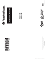
Specifications
Model M1WL-65MB M2WL-65MB
Nominal Diameter - inch
(mm)
6.5
(165mm).
6.5
(165mm).
Description 2-Way 2-Way
Nominal Impedance (Ohms) 4Ω 4Ω
Frequency Response (Hz) 38-22kHz 40-24kHz
Power Handling - Watts
(RMS/Peak) 75/300 150/600
Sensitivity (2.83V/1M) 92dB 92dB
Grille/Trim Ring YES (mounted) YES (mounted)
LED Current Draw .25 Amps .25 Amps
Recommended Fused Rating 1 Amp 1 Amp
LED Voltage Range 9-16 Volts 9-16 Volts
Overall Speaker (A) 7.11”
(180.5mm)
7.11”
(180.5mm)
Bolt Diameter (B) 6.12”
(155.5mm)
6.12”
(155.5mm)
Overall Height (C) 9.57”
(243.2mm)
9.57”
(243.2mm)
Overall Length (D) 8.16”
(207.3mm)
8.16”
(207.3mm)
*Rockford Fosgate determines its rated frequency response range at -6 dB below its nominal sensitivity
at upper and lower extents of a speaker’s output.
M1/M2 Moto Can Dimensions
VERIFIED WITH KLIPPEL
To adorn the ‘Verified with Klippel’ mark, the qualifying company’s loudspeaker engineering personnel must be trained
and certified by Klippel prior to using the three separate Klippel systems to design, develop and test. Rockford Fosgate
has made the investment in Klippel to deliver the best possible speakers and subwoofers to their customers.
illus.-1.1
A
B
C
D

4
Diagrams
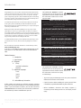
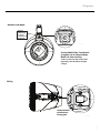
Speaker Adjustment
Remove the speaker to
reveal the multi-point
mounting option to make
sure your speaker is
mounted correctly. No
matter what direction the
speaker is mounted, it
should always look like the
image above.
3°
illus.-3.1
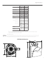
Rear Medallion Rotation Rotate Medallion to look like
image aer mounting Wake Cans
The bottom of the Diamond R
should be down like the image
when mounted
illus.-3.2
Grill Options (Included)
illus.-2.1 M2 only

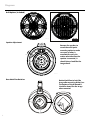
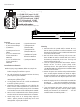
5
Insert covered
wire harness
wiring port.
Wiring
illus.-4.2
Rotation Lock-down
Use included Safety Torx Wrench
to tighten can to clamp to keep
Wake Can from swivling.
*If the cap does not fully snap in aer
tightening, then the bolt is not tight
enough.
Remove
plastic plug
to access
rotation lock-
down torx.
illus.-3.3
Diagrams

6
Contents
Installation Considerations
Before beginning any installation, follow these simple rules:
1. Be sure to carefully read and understand the instructions
before attempting to install these speakers.
2. For safety, disconnect the negative lead from the battery
prior to beginning the installation.
3. For easier assembly, we suggest you run all wires prior to
mounting your speakers in place.
4. Use high quality connectors for a reliable installation and
to minimize signal or power loss.
5. Think before you drill! Be careful not to cut or drill into gas
tanks, fuel lines, brake or hydraulic lines, vacuum lines or
electrical wiring when working on any vehicle. If installation
in a boat, take care not to cut or drill through the main hull.
6. Never run wires underneath the vehicle. Running the wires
inside the vehicle or hull area provides the best protection.
7. Avoid running wires over or through sharp edges. Use
rubber or plastic grommets to protect any wires routed
through metal, especially the firewall.
• (1) Pair Moto Can Speakers
• (1) Pair Universal Clamps
• (4) Grommets
• (4) Safety Inserts for Screw
Clamp
• (2) 1” to 1.6” Rubber Clamp
Inserts and Stainless
Hardware
• (2) 1.6” to 2” Rubber Clamp
Inserts and Stainless
Hardware
• (2) Speaker Harnesses
• (1) Pair Sport Grills
(Installed on M1)
• (1) Pair Sport Grills
(Installed on M2, not
available on M1)
• (1) Allen Bit For Speaker
Removal For Rotation
• (1) Safety Torx Wrench
Mounting
1. Determine where the speakers will be mounted. Be sure
that the mounting location has suicient clearance in all
direction for the speaker to swivel; conduct a full rotation to
ensure there is not obstruction.
2. Mark the location where the wiring will come out near
where the Moto can will be mounted. Drill a 7/16” hole in
the location you marked for your wire exit. The wiring will
connect to the rear of the can illus.-4.2.
3. Insert the supplied grommet and feed the wire harness
through. Be sure to observe proper polarity when
connecting the wires. The speaker harness’s negative wire
is the BLACK 18 AWG wire and the Positive is the RED 18 AWG
wire in the 6 pin connector illus.-4.3.
4. Remove the plastic cover over the safety torx bolt to allow
access to loosen/tighten the wake can. Do this to adjust
the angle of the wake can, then tighten the safety torx bolt
to make sure it does not move. Replace plastic cover over
safety torx bolt illus.-3.3.
5. Rotate the medalion on the rear of the wake can to look like
the image in illus.-3.2. This can be turned le or right to align
the medalion. You will hear/feel a clicking when you rotate
it.
6. If you need to rotate the speaker, remove the (6) screws
holding th speaker and grill on. Pull the speaker slightly
towards you and rotate it until it looks like illus.-1.1. Use the
predrilled holes to reinstall the speaker illus.-3.1.
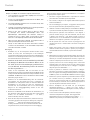
Installation
(1)
(3)
(5)
(2)
(4)
(6)
14”
(355mm)
illus.-4.3
illus.-4.4
1 - BLACK (Speaker Negative, 18 AWG)
2 - YELLOW (12V + Input, 22 AWG)
3 - RED (Speaker Positive, 18 AWG)
4 - GREEN (Ground Input, 22 AWG)
5 - RED (Ground Input, 22 AWG)
6 - BLUE (Ground Input, 22 AWG)
Included with speakers
Connector is DEUTSCH™/Amphenol style DT06-4S
15”
(380mm)

7
Français Español
Considérations d’installation
Avant de commencer toute installation, suivez ces règles simples:
1. Assurez-vous de lire attentivement et de comprendre les instructions
avant de tenter d’installer ces enceintes.
2. Pour plus de sécurité, débranchez le fil négatif de la batterie avant de
commencer l’installation.
3. Pour un assemblage plus facile, nous vous suggérons de faire passer
tous les fils avant de monter vos enceintes en place.
4. Utilisez des connecteurs de haute qualité pour une installation fiable et
pour minimiser la perte de signal ou de puissance.
5. Réfléchissez avant de percer! Veillez à ne pas couper ou percer dans les
réservoirs d’essence, les conduites de carburant, les conduites de frein
ou hydrauliques, les conduites de vide ou le câblage électrique lorsque
vous travaillez sur un véhicule. En cas d’installation dans un bateau,
veillez à ne pas couper ou percer la coque principale.
6. Ne jamais faire passer les fils sous le véhicule. Faire passer les fils à
l’intérieur du véhicule ou dans la zone de la coque offre la meilleure
protection.
7. Évitez de faire passer les fils sur ou à travers des arêtes vives. Utilisez des
œillets en caoutchouc ou en plastique pour protéger les fils acheminés à
travers le métal, en particulier le pare-feu.
Montage
1. Déterminez où les haut-parleurs seront montés. Assurez-vous que
l’emplacement de montage dispose d’un dégagement suffisant dans toutes les
directions pour que l’enceinte puisse pivoter; effectuer une rotation complète
pour s’assurer qu’il n’y a pas d’obstruction.
2. Marquez l’emplacement où le câblage sortira près de l’endroit où la moto
peut être montée. Percez un trou de 7/16 po à l’emplacement que vous avez
marqué pour la sortie du fil. Le câblage se connectera à l’arrière de la boîte.
3. Insérez l’œillet fourni et faites passer le faisceau de câbles. Assurez-vous de
respecter la polarité lors de la connexion des fils. Le fil négatif du faisceau
d’enceintes est le fil NOIR 18 AWG et le fil positif est le fil ROUGE 18 AWG
dans le connecteur à 6 broches.
4. Retirez le couvercle en plastique sur le boulon torx de sécurité pour permettre
l’accès pour desserrer / serrer la boîte de sillage. Faites cela pour ajuster
l’angle de la boîte de sillage, puis serrez le boulon torx de sécurité pour vous
assurer qu’il ne bouge pas. Remettez le couvercle en plastique sur le boulon
torx de sécurité.
5. Faites pivoter le médaillon à l’arrière de la canette de sillage pour ressembler
à l’image. Cela peut être tourné à gauche ou à droite pour aligner
le médaillon. Vous entendrez / ressentirez un clic lorsque vous le tournerez.
6. Si vous devez faire pivoter l’enceinte, retirez les (6) vis qui maintiennent
l’enceinte et la grille en marche. Tirez légèrement l’enceinte vers vous et
faites-la pivoter jusqu’à ce qu’elle ressemble. Utilisez les trous pré-
percés pour réinstaller l’enceinte.
Consideraciones para la instalación
Antes de comenzar cualquier instalación, siga estas simples reglas:
1. Asegúrese de leer detenidamente y comprender las instrucciones antes
de intentar instalar estos altavoces.
2. Por seguridad, desconecte el cable negativo de la batería antes de
comenzar la instalación.
3. Para facilitar el montaje, le sugerimos que pase todos los cables antes de
montar los altavoces en su lugar.
4. Utilice conectores de alta calidad para una instalación confiable y para
minimizar la pérdida de señal o energía.
5. ¡Piense antes de perforar! Tenga cuidado de no cortar ni perforar tanques
de gasolina, líneas de combustible, líneas de frenos o hidráulicas, líneas
de vacío o cableado eléctrico cuando trabaje en cualquier vehículo. Si
se instala en una embarcación, tenga cuidado de no cortar ni perforar el
casco principal.
6. Nunca coloque cables debajo del vehículo. Pasar los cables dentro del
vehículo o en el área del casco proporciona la mejor protección.
7. Evite pasar cables sobre o a través de bordes afilados. Utilice arandelas
de goma o plástico para proteger los cables que atraviesan el metal,
especialmente el cortafuegos.
Montaje
1. Determine dónde se montarán los altavoces. Asegúrese de que la
ubicación de montaje tenga suficiente espacio libre en todas las
direcciones para que el altavoz gire; Realice una rotación completa para
asegurarse de que no haya obstrucciones.
2. Marque la ubicación donde saldrá el cableado cerca de donde se montará
el Moto. Taladre un agujero de 7/16 ”en la ubicación que marcó para la
salida del cable. El cableado se conectará a la parte trasera de la lata.
3. Inserte la arandela suministrada y pase el mazo de cables. Asegúrese de
observar la polaridad adecuada al conectar los cables. El cable negativo
del arnés del altavoz es el cable NEGRO 18 AWG y el positivo es el cable
ROJO 18 AWG en el conector de 6 clavijas.
4. Quite la cubierta de plástico sobre el perno Torx de seguridad para permitir
el acceso para aflojar / apretar la lata de vela. Haga esto para ajustar el
ángulo de la lata de estela, luego apriete el perno Torx de seguridad para
asegurarse de que no se mueva. Vuelva a colocar la cubierta de plástico
sobre el perno Torx de seguridad.
5. Gire el medallón en la parte posterior de la lata para que se parezca a la
imagen. Esto se puede girar hacia la izquierda o hacia la derecha
para alinear la medalla. Oirá / sentirá un clic cuando lo gire.
6. Si necesita girar el altavoz, retire los (6) tornillos que sujetan el altavoz
y la rejilla. Tire del altavoz ligeramente hacia usted y gírelo hasta que
parezca. Utilice los agujeros pretaladrados para reinstalar el
altavoz.
illus.-4.2
illus.-3.2
illus.-1.1
illus.-3.1
illus.-3.3
illus.-4.3
illus.-1.1
illus.-3.1
illus.-3.2
illus.-3.3
illus.-4.3
illus.-4.2

8
Deutsch
Einbauüberlegungen
Befolgen Sie vor Beginn einer Installation die folgenden einfachen Regeln:
1. Lesen und verstehen Sie die Anweisungen sorgfältig, bevor Sie versuchen,
diese Lautsprecher zu installieren.
2. Trennen Sie aus Sicherheitsgründen das Minuskabel von der Batterie, bevor
Sie mit der Installation beginnen.
3. Zur einfacheren Montage empfehlen wir, dass Sie alle Kabel verlegen, bevor
Sie Ihre Lautsprecher anbringen.
4. Verwenden Sie hochwertige Steckverbinder für eine zuverlässige Installation
und zur Minimierung von Signal- oder Stromausfällen.
5. Denken Sie nach, bevor Sie bohren! Achten Sie darauf, bei Arbeiten
an Fahrzeugen keine Gastanks, Kraftstoffleitungen, Brems- oder
Hydraulikleitungen, Vakuumleitungen oder elektrischen Leitungen zu
schneiden oder in diese zu bohren. Achten Sie beim Einbau in ein Boot
darauf, dass Sie den Hauptrumpf nicht durchschneiden oder durchbohren.
6. Führen Sie niemals Kabel unter dem Fahrzeug. Das Verlegen der Kabel im
Fahrzeug- oder Rumpfbereich bietet den besten Schutz.
7. Verlegen Sie keine Drähte über oder durch scharfe Kanten. Verwenden
Sie Gummi- oder Kunststofftüllen, um alle durch Metall verlegten Drähte,
insbesondere die Firewall, zu schützen.
Befestigung
1. Bestimmen Sie, wo die Lautsprecher montiert werden sollen.
Stellen Sie sicher, dass der Montageort in alle Richtungen
genügend Spiel hat, damit sich der Lautsprecher schwenken kann.
Führen Sie eine vollständige Rotation durch, um sicherzustellen,
dass keine Hindernisse vorhanden sind.
2. Markieren Sie die Stelle, an der die Verkabelung in der Nähe
der Montage der Moto-Dose herauskommt. Bohren Sie an
der Stelle, die Sie für Ihren Drahtausgang markiert haben,
ein 7/16-Zoll-Loch. Die Verkabelung wird an der Rückseite
der Dose angeschlossen illus.-4.2.
3. Setzen Sie die mitgelieferte Tülle ein und führen Sie den
Kabelbaum durch. Achten Sie beim Anschließen der Drähte auf die
richtige Polarität. Das Minuskabel des Lautsprecherkabels ist das
SCHWARZE 18-AWG-Kabel und das Pluskabel das ROTE 18-AWG-
Kabel im 6-poligen Stecker.
4. Entfernen Sie die Kunststoabdeckung über der Sicherheits-
Torx-Schraube, um den Zugang zum Lösen / Festziehen der
Nachlaufdose zu ermöglichen. Stellen Sie dazu den Winkel der
Nachlaufdose ein und ziehen Sie dann die Sicherheits-Torx-
Schraube fest, um sicherzustellen, dass sie sich nicht bewegt.
Bringen Sie die Kunststoabdeckung wieder an der Torx-
Sicherheitsschraube an.
5. Drehen Sie die Medaille auf der Rückseite der Nachlaufdose, um
wie im Bild zu sehen. Dies kann nach links oder rechts gedreht
werden, um die Medaille auszurichten. Sie hören /
fühlen ein Klicken, wenn Sie es drehen.
6. Wenn Sie den Lautsprecher drehen müssen, entfernen Sie die (6)
Schrauben, mit denen der Lautsprecher befestigt ist, und grillen
Sie weiter. Ziehen Sie den Lautsprecher leicht in Ihre
Richtung und drehen Sie ihn, bis er aussieht. Verwenden Sie die
vorgebohrten Löcher, um den Lautsprecher neu zu installieren.
Italiano
Considerazioni sull’installazione
Prima di iniziare qualsiasi operazione d’installazione, vi consigliamo
di seguire queste semplici regole:
1. Assicurarsi di leggere attentamente e comprendere le istruzioni
prima di tentare di installare questi altoparlanti.
2. Per sicurezza, scollegare il cavo negativo dalla batteria prima di
iniziare l’installazione.
3. Per un assemblaggio più semplice, ti suggeriamo di far passare
tutti i cavi prima di montare gli altoparlanti in posizione.
4. Utilizzare connettori di alta qualità per un’installazione aidabile
e per ridurre al minimo la perdita di segnale o di alimentazione.
5. Pensa prima di perforare! Fare attenzione a non tagliare o
perforare serbatoi del gas, tubi del carburante, tubi dei freni
o idraulici, linee del vuoto o cavi elettrici quando si lavora su
qualsiasi veicolo. In caso di installazione su un’imbarcazione, fare
attenzione a non tagliare o perforare lo scafo principale.
6. Non far passare mai i cavi sotto il veicolo. Il passaggio dei cavi
all’interno del veicolo o nell’area dello scafo fornisce la migliore
protezione.
7. Evitare di far passare i cavi sopra o attraverso bordi taglienti.
Utilizzare anelli di tenuta in gomma o plastica per proteggere i
cavi instradati attraverso il metallo, in particolare il firewall.
Montaggio
1. Determina dove verranno montati gli altoparlanti. Assicurarsi che
la posizione di montaggio abbia uno spazio suiciente in tutte le
direzioni per consentire all’altoparlante di ruotare; eseguire una
rotazione completa per assicurarsi che non vi siano ostruzioni.
2. Segna la posizione in cui uscirà il cablaggio vicino a dove verrà
montata la Moto can. Praticare un foro da 7/16 “nella posizione
contrassegnata per l’uscita del cavo. Il cablaggio si collegherà
alla parte posteriore della lattina.
3. Inserire il gommino in dotazione e far passare il cablaggio.
Assicurarsi di osservare la corretta polarità quando si collegano i
fili. Il cavo negativo del cablaggio dell’altoparlante è il cavo NERO
18 AWG e il positivo è il cavo ROSSO 18 AWG nel connettore a 6 pin.
4. Rimuovere il coperchio di plastica sopra il bullone torx di sicurezza
per consentire l’accesso per allentare / stringere la scia. Fai
questo per regolare l’angolo della scia, quindi stringi il bullone
torx di sicurezza per assicurarti che non si muova. Riposizionare il
coperchio di plastica sul bullone torx di sicurezza.
5. Ruota il medaglione sul retro della scia per assomigliare
all’immagine all’interno. Questo può essere ruotato a
sinistra oa destra per allineare il medaglione. Sentirai / avvertirai
un clic quando lo ruoterai.
6. Se è necessario ruotare l’altoparlante, rimuovere le (6) viti
che fissano l’altoparlante e la griglia. Tirare leggermente
l’altoparlante verso di sé e ruotarlo finché non sembra.
Utilizzare i fori preforati per reinstallare l’altoparlante.
illus.-3.1
illus.-1.1
illus.-3.2
illus.-3.3
illus.-4.3
illus.-4.2
illus.-4.3
illus.-3.3
illus.-3.2
illus.-1.1
illus.-3.1

9

10

11

12
Warranty
Rockford Corporation oers a limited warranty on Rockford Fosgate products on the following terms:
Length of Warranty
POWER Amplifiers – 2 Years
BMW® Direct Fit Speakers – 2 Years
PUNCH® & PRIME® Amplifiers – 1 Year
Speakers, Signal Processors, Accessories and Capacitors – 1 Year
All marine, motorcycle, motorsport products - 2 Years
Any Factory Refurbished Product – 90 Days (receipt required)
What is Covered
This warranty applies only to Rockford Fosgate products sold to consumers by authorized Rockford Fosgate dealers in the United
States of America. Products purchased by consumers from an Authorized Rockford Fosgate Dealer in another country are covered
only by that country’s Distributor and not by Rockford Corporation.
Who is Covered
This warranty covers only the original purchaser of Rockford product purchased from an authorized Rockford Fosgate dealer in the
United States. In order to receive service, the purchaser must provide Rockford with a copy of the receipt stating the customer name,
dealer name, product purchased and date of purchase.
Products found to be defective during the warranty period will be repaired or replaced (with a product deemed to be equivalent) at
Rockford’s discretion.
What is Not Covered
1. Damage caused by accident, abuse, improper installation, operations, the, water (on non-Element Ready products).
2. Any cost or expense related to the removal or reinstallation of product.
3. Service performed by anyone other than Rockford or an authorized Rockford Fosgate service center.
4. Any product which has had the serial number defaced, altered, or removed.
5. Subsequent damage to other components.
6. Any product purchased outside the U.S.
7. Any product not purchased from an authorized Rockford Fosgate dealer. Refer to rockfordfosgate.com dealer locator for more
detail.
Limit on Implied Warranties
Any implied warranties including warranties of fitness for use and merchantability are limited in duration to the period of the express
warranty set forth above. Some states do not allow limitations on the length of an implied warranty, so this limitation may not apply.
No person is authorized to assume for Rockford Fosgate any other liability in connection with the sale of the product.
How to Obtain Service
Please call 1-800-669-9899 for Rockford Customer Service. You must obtain an RA# (Return Authorization number) to return any prod-
uct to Rockford Fosgate. You are responsible for shipment of product to Rockford.
EU Warranty
This product meets the current EU warranty requirements, see your Authorized dealer for details.

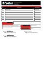
Drawing Title: MANUAL, OWNER, RF, MOTO CAN, M1WL-65MB/M2WL-65MB
Drawing/Part NO: 1230-74972
AINITIALRELEASE ENG.SERVICES
PROCESSEDBYDESCRIPTIONREV
VERSION‐REVISION 01‐B
CONFIDENTIAL COPYRIGHT 2019 ROCKFORD CORPORATION THIS DRAWING IS THE PROPERTY OF
ROCKFORD CORPORATION AND EMBODIES CONFIDENTIAL INFORMATION, TRADE SECRET
INFORMATION, AND/OR KNOW-HOW WHICH IS THE PROPERTY OF ROCKFORD CORPORATION. BY
ACCECPTING THIS DRAWING, THE RECIPIENT AGREES NOT TO PROVIDE, OR OTHERWISE MAKE
AVAILABLE, THE DRAWING, OR ANY INFORMATION OR KNOW-HOW EMBODIED THERE IN, TO ANY
THIRD PARTY WITHOUT PRIOR WRITTEN AUTHORIZATION.
BCHNAGEDWORDINGONFRONTCOVER
1.DOCUMENTHISTORY
ENG.SERVICES
Signature:
Email:
Signature:
Email:
Signature:
Email:
Kurt Chen (Mar 1, 2021 07:56 MST)
Kurt Chen
brad.marvi[email protected]
Ted Sardina (Mar 1, 2021 08:44 MST)
Ted Sardina

1230-74972-01-B
Final Audit Report 2021-03-01
Created: 2021-02-25
By: Richard Dudley ([email protected])
Status: Signed
Transaction ID: CBJCHBCAABAActd4jEalVye7mvzPGQQOK340T2OlTIwp
"1230-74972-01-B" History
Document created by Richard Dudley ([email protected])
2021-02-25 - 8:16:54 PM GMT- IP address: 204.126.173.136
Document emailed to Kurt Chen ([email protected]) for signature
2021-02-25 - 8:17:08 PM GMT
Email viewed by Kurt Chen ([email protected])
2021-03-01 - 2:56:28 PM GMT- IP address: 68.228.212.120
Document e-signed by Kurt Chen ([email protected])
Signature Date: 2021-03-01 - 2:56:45 PM GMT - Time Source: server- IP address: 68.228.212.120
Document emailed to Brad Marvin ([email protected]) for signature
2021-03-01 - 2:56:47 PM GMT
Email viewed by Brad Marvin ([email protected])
2021-03-01 - 3:33:40 PM GMT- IP address: 204.126.173.136
Document e-signed by Brad Marvin ([email protected])
Signature Date: 2021-03-01 - 3:33:53 PM GMT - Time Source: server- IP address: 204.126.173.136
Document emailed to Ted Sardina ([email protected]) for signature
2021-03-01 - 3:33:55 PM GMT
Email viewed by Ted Sardina ([email protected])
2021-03-01 - 3:43:53 PM GMT- IP address: 204.126.173.136
Document e-signed by Ted Sardina ([email protected])
Signature Date: 2021-03-01 - 3:44:33 PM GMT - Time Source: server- IP address: 204.126.173.136
Agreement completed.
2021-03-01 - 3:44:33 PM GMT
-
 1
1
-
 2
2
-
 3
3
-
 4
4
-
 5
5
-
 6
6
-
 7
7
-
 8
8
-
 9
9
-
 10
10
-
 11
11
-
 12
12
-
 13
13
-
 14
14


Rockford Fosgate M1WL-65MB Instrucciones de operación
- Tipo
- Instrucciones de operación
En otros idiomas
Documentos relacionados
-
Rockford Fosgate M2WL-10H El manual del propietario
-
 Rockford Fosgate M2WL-8 Manual de usuario
-
 Rockford Fosgate M2 ELEMENT READY M2D2-10SB Manual de usuario
-
 Rockford Fosgate Element Ready M2D2-10I Installation & Operation Manual
-
Rockford Fosgate Punch PM2652W-MB Manual de usuario
-
Rockford Fosgate M2-8HB Installation & Operation Manual
-
Rockford Fosgate PunchPM282HW-B Installation & Operation
-
 Rockford Fosgate ELEMENT READY M0-65 Manual de usuario
-
 Rockford Fosgate M1D4-10 Manual de usuario
-
Rockford Fosgate R1525X2 Manual de usuario


