Simplicity 074003-0 Manual de usuario
- Categoría
- Herramientas eléctricas
- Tipo
- Manual de usuario

7711 PPiieeccee AAiirr TTooooll KKiitt
OOppeerraattoorr’’ss MMaannuuaall
P/N 201667, Rev A, 01/11/2007

Thank you for purchasing this quality-built Briggs & Stratton accessory kit. We are pleased that you’ve placed your
confidence in the Briggs & Stratton brand. When operated and maintained according to the instructions in this manual,
your Briggs & Stratton accessory will provide years of dependable service.
This manual contains safety information to make you aware of the hazards and risks associated with air tool products and
how to avoid them. Because Briggs & Stratton does not necessarily know all the applications this accessory could be
used for, it is important that you read and understand these instructions. Keep this manual for future reference.
This accessory requires assembly before use. Refer to the Assembly section of this manual for instructions. Follow the
instructions completely.
Make note of the product identification below:
Model Name _71 Piece Air Tool Kit______________
Date Purchased _______________________________
Store Purchased _______________________________
Where to Find Us
You never have to look far to find Briggs & Stratton support and service for your product. Consult your Yellow Pages.
There are over 30,000 Briggs & Stratton authorized service dealers worldwide who provide quality service. You can also
contact Briggs & Stratton Customer Service by phone at 1-800-743-4115 or on the Internet at
BRIGGSandSTRATTON.COM.
Briggs & Stratton Power Products Group, LLC
900 North Parkway
Jefferson, WI 53549
Copyright © 2007 Briggs & Stratton Power Products Group, LLC. All rights reserved.
No part of this material may be reproduced or transmitted in any form by any means
without the express written permission of Briggs & Stratton Power Products Group, LLC.

1
SSaaffeettyy RRuulleess..............................................................................................................22
Hazard Symbols and Meanings ...................................................2
AAsssseemmbbllyy ....................................................................................................................44
Air Motor Lubrication ....................................................................5
FFeeaattuurreess aanndd CCoonnttrroollss ......................................................................................66
OOppeerraattiioonn ....................................................................................................................88
Air Die Grinder .............................................................................8
1/2 in. Drive Impact Tool...............................................................9
150mm Air Hammer....................................................................10
3/8 in. Drive Ratchet Wrench ......................................................11
Other Supplied Accessories .......................................................12
MMaaiinntteennaannccee ........................................................................................................1144
Impact Mechanism Lubrication ..................................................14
Storage.......................................................................................14
TTrroouubblleesshhoooottiinngg..................................................................................................1155
SSppeecciiffiiccaattiioonnss......................................................................................................1166
Air Supply...................................................................................16
Air Hose......................................................................................16
Air Die Grinder............................................................................16
Air Hammer ................................................................................16
Air Impact Tool............................................................................16
Air Ratchet Wrench.....................................................................16
WWaarrrraannttyy ..................................................................................................................1177

2 BRIGGSandSTRATTON.COM
SSaaffeettyy RRuulleess
This is the safety alert symbol. It is
used to alert you to potential personal
injury hazards. Obey all safety
messages that follow this symbol to
avoid possible injury or death.
The safety alert symbol ( ) is used with a
signal word (DANGER, CAUTION, WARNING),
a pictorial and/or a safety message to alert you
to hazards. DANGER indicates a hazard which,
if not avoided, will result in death or serious
injury. WARNING indicates a hazard which, if
not avoided, could result in death or serious
injury. CAUTION indicates a hazard which, if not
avoided, might result in minor or moderate
injury. NOTICE indicates a situation that could
result in equipment damage. Follow safety
messages to avoid or reduce the risk of injury or
death.
Hazard Symbols and Meanings
Explosion
Compressed Air
Inhalation
Noise Read Manual
Electrical Shock
Flying Objects
Air Injection
SSAAVVEE TTHHEESSEE IINNSSTTRRUUCCTTIIOONNSS
You will need this manual for safety warnings and precautions, assembly instructions, operating and
maintenance procedures. Keep this manual in a dry and safe place for future reference.

3
• DO NOT direct air stream at self or others.
• DO NOT attempt to repair air hose(s).
• Always wear ANSI Z87.1 approved safety glasses with
side shields.
• DO NOT adjust pressure greater than maximum
rating of attachments or inflatables.
WWAARRNNIINNGG
• DO NOT spray flammable or combustible liquids while
smoking, near sparks, open flames, pilot lights, any
ignition source, or in confined areas.
• Spray in an open, well ventilated area at least 20 feet
(6.1 meters) away from compressor or other ignition
source.
WWAARRNNIINNGG
• Before using this product, read this Operator’s Manual
and follow all Safety Rules and Operating Instructions
listed.
• Make this manual available to other users of this
equipment.
WWAARRNNIINNGG
WWAARRNNIINNGG
Spraying flammable or combustible
liquids can cause fire or explosion.
Compressor may produce sparks
during operation, which can ignite
flammable or combustible vapors.
Compressed air stream from hose or
tank drain can cause soft tissue
damage to exposed skin and can
propel objects leading to severe injury
and / or property damage.
Exceeding pressure rating of
attachments or inflatables can cause
severe injury and/or property
damage.
Failure to read and follow instructions
in manual can result in bodily injury
and / or property damage.
• Disconnect the tool from the air supply before
changing tools or accessories, when servicing and
when not in use.
• Do not wear loose fitting clothing and jewelry that
may become caught in moving parts.
• Do not depress trigger when connecting the air
supply.
• Always use accessory fittings designed for use with
air tools.
• Make sure all air connections are secure and check
air hoses, air tools, and accessories for weak or worn
condition before each use.
• Before each use, drain water out of air compressor
tank and condensation from air lines.
NNOOTTIICCEE
Air tools are critical parts of a high-pressure
system.

4 BRIGGSandSTRATTON.COM
AAsssseemmbbllyy
The air tools need some assembly and
lubrication before first use. Use the instructions
below to attach air fittings (coupling plugs) and
lubricate the air motors.
Attach Air Fittings
This kit is supplied with “type I/T” air hose
connector fittings. Attach a coupling plug (male
fitting) to the tool, as follows:
1. Remove shipping cap from air inlet of air
tool and discard cap.
2. Wrap male threads of plug with two turns of
supplied thread seal (teflon) tape, applied
counterclockwise.
3. Thread plug into air tool’s air inlet until snug.
4. Using supplied wrenches, tighten plug
another 1/2 to 1 full turn.
Repeat steps 1-4 above for the other air tools in
the kit.
Confirm that the air tool plug fits the quick-
connect coupling (female fitting) at the end of
your air hose. If you are unable to make the
connection, change the air hose coupling as
follows:
1. Using adjustable wrenches or the supplied
wrenches, detach the quick connect
coupling from the air hose.
2. Carefully remove all traces of sealing tape
or joint compound from threads on air hose
fitting.
3. Wrap male threads of air hose fitting with
two turns of supplied thread seal tape,
applied counterclockwise.
4. Thread supplied quick-connect fitting onto
air hose, being careful to not cross thread
the connection. Finger tighten until snug
5. Using supplied wrenches, tighten plug
another 1/2 to 1 full turn.
Your air tools are ready for initial air motor
lubrication.

5
Air Motor Lubrication
IMPORTANT – These air tools require
lubrication BEFORE initial use and BEFORE
and AFTER each additional use for the life of
the tool.
To properly lubricate the air tool:
1. Disconnect air tool from air hose and hold
tool upside down.
2. Pull air tool’s trigger and pour one teaspoon
of air tool oil (supplied) in tool’s air inlet
fitting.
3. Push or rotate reverse control back and forth
from stop to stop to help circulate oil in
motor.
4. Connect air tool to air supply and cover its
air exhaust port with a towel. Run the tool in
both forward and reverse directions for
20 seconds.
5. Excess oil will discharge from exhaust port
when air pressure is applied. Always direct
exhaust port away from people or objects.
The air tool is now lubricated and ready for use.
Other Recommendations
These air tools require lubrication during
operation. This will extend the life of the tool. As
shown below, air (A) is supplied by the
compressor, passes through a water filter (B), a
pressure regulator (C), an automatic oiler (D),
and through a quick connect air coupling (E).
One end of the air hose (G) is fitted with a
connection plug (F) and a quick connect
coupler (E) . Each air tool will have a connection
plug (F) to receive the air (H).
Non-Lubricated tools, such as the air blow gun
tool or the tire inflation tool, uses a similar in-line
air supply that does not have the oiler device
(D). Never use an oiler in the air supply for
spray painting operations.
C
B F F
A
D
G HE E

6 BRIGGSandSTRATTON.COM
FFeeaattuurreess aanndd CCoonnttrroollss
Read this Operator’s Manual and safety rules
before operating your air tool(s). Compare
these illustrations with your air tools to
familiarize yourself with the location of various
controls and adjustments. Save this manual for
future reference.
Die Grinder
1/2” Drive Impact Tool
A - Collet
B - Trigger Lock
C - Trigger
D - Air Discharge Port
A - Oil Fill Location
B - Forward/Reverse Button
C - Air Discharge Port
D - Trigger
E - Air Flow Control (Regulator)
C
B
A
D
CBA
D
E

7
150mm Air Hammer 3/8” Drive Ratchet Wrench
Air Blow Gun Tool
A - Spring Retainer
B - Air Discharge Port
C - Trigger
A - Trigger
B - Install Removable Spray Tip Here
A - Forward/Reverse Lever
B - Air Discharge Port
C - Trigger
B
A
CBA
CBA

8 BRIGGSandSTRATTON.COM
OOppeerraattiioonn
This section will describe proper operation for
each tool supplied in the kit.
Before each use, drain water out of the air
compressor tank and condensation from the air
lines. After clearing air compressor moisture and
lubricating the tool, connect it to an air hose of a
recommended size.
Air Die Grinder
Description
This air die grinder is designed for grinding,
polishing, deburring and smoothing sharp
edges. The die grinder uses standard ¼” shank
grinding stones or sanding mandrels.
Air Die Grinder Operation
NOTICE This die grinder requires lubrication
BEFORE initial use and BEFORE and AFTER
each additional use throughout its life. Follow
the instructions in Air Motor Lubrication
described in Assembly to lubricate this tool.
CAUTION Inspect the tool before use to ensure
there are no loose components and for the
absence of defects or other conditions that may
affect safe operation.
Before each use, drain water out of air
compressor tank and condensation from air
lines.
Use the supplied hand wrenches (spanners) to
remove the collet cap when changing collets or
installing grinding stones or sanding mandrels.
The supplied grinding stones and sanding
drums are rated for 25,000 rpm or more.
CAUTION Only use die grinder accessories
rated for 22,000 rpm or more.
To operate grinder, put on your safety glasses or
full face shield and hearing protection. While
firmly gripping the grinder, press the outer
• When operating air die grinder, always wear ANSI-
approved hearing protection.
• Always wear ANSI Z87.1 approved safety glasses with
side shields.
• Wear a full face shield if you are producing metal
filings or wood chips.
• Wear an ANSI approved dust mask or respirator
when working around metal, wood, and chemical
dusts and mists.
WWAARRNNIINNGG
Grinding operations cause loud
noises.
Grinding stones and sanding drums
can disintegrate without warning,
causing flying debris.

9
trigger lock lever forward (towards collet) and
press down the speed lever.
Since the speed of this die grinder is
22,000 rpm, a large amount of material can
quickly be removed - sometimes more than you
want! Therefore, it is important to use a gentle
touch. Frequently stop grinding and blow away
debris to check grinding progress.
1/2 in. Drive Impact Tool
Description
This air impact tool is designed for removing
and installing fasteners and is used as a light-
duty general-purpose tool by hobbyists and
mechanics. It is equipped with a 1/2 in. chuck
and eight impact-quality sockets. This tool is not
intended for heavy duty use or for assembly line
operations.
It employs a constant pressure throttle control, a
push-button reversing control, and a knurled
knob air flow control (regulator).
NOTICE This impact tool requires lubrication
BEFORE initial use and BEFORE and AFTER
each additional use throughout its life. Follow
the instructions in Air Motor Lubrication
described in Assembly to lubricate this tool.
In addition to daily lubrication, perform the
Impact Mechanism Lubrication procedure
described in Maintenance once each month.
Impact Tool Operation
Before each use, drain water out of air
compressor tank and condensation from air
lines.
CAUTION Inspect the tool before use to ensure
there are no loose components and for the
absence of defects or other conditions which
may affect safe operation.
Install the desired socket or attachment. Tug on
the socket or attachment to ensure it is firmly
attached to the air tool.
• When operating air impact tool, always wear ANSI-
approved hearing protection.
• Always wear ANSI Z87.1 approved safety glasses with
side shields.
• Wear an ANSI approved dust mask or respirator
when working around metal, wood, and chemical
dusts and mists.
WWAARRNNIINNGG
Impact tool operation causes loud
noises.
Impact tool attachments can
disintegrate without warning while in
use, causing flying debris.

10 BRIGGSandSTRATTON.COM
CAUTION Always use accessory fittings and
sockets designed for use with impact tools. Do
not use worn-out or hand-tool sockets.
NOTICE The impact tool should never be used
to set torque. Use a torque wrench to set the
torque.
To remove nuts, set the tool’s regulator to its
maximum setting by pushing in and turning the
knurled knob to position 4.
To install nuts, set the regulator to it’s minimum
(1) or medium (2 or 3) setting. Do not
over-tighten fasteners.
Forward and reverse directions are controlled by
a push button. Press the button fully forward for
clockwise socket rotation. Press the knob fully
backward for counter-clockwise socket rotation.
150mm Air Hammer
Description
This air hammer is designed for cutting through
rusted metal or bolts and for removing mortar
from cement blocks or bricks.
Air Hammer Operation
NOTICE This air hammer requires lubrication
BEFORE initial use and BEFORE and AFTER
each additional use throughout its life. Follow
the instructions in Air Motor Lubrication
described in Assembly to lubricate this tool.
CAUTION Inspect the tool before use to ensure
there are no loose components. Make sure
spring retainer and all air connections are
secure and for the absence of defects or other
conditions that may affect safe operation.
Before each use, drain water out of air
compressor tank and condensation from air
lines.
To load a chisel, remove the spring retainer from
the air hammer by rotating the spring
• When operating air hammer, always wear ANSI-
approved hearing protection.
• Always wear ANSI Z87.1 approved safety glasses with
side shields.
• Wear a full face shield if you are producing metal
splinters or working overhead.
• Wear an ANSI approved dust mask or respirator
when working around metal, wood, and chemical
dusts and mists.
WWAARRNNIINNGG
Air hammer operation causes loud
noises and flying debris.
Air hammer attachments can
disintegrate without warning while in
use, causing flying debris.

11
counterclockwise. Insert the desired chisel. Slide
the spring retainer over the chisel and thread it
onto the air hammer.
Always tighten the spring retainer before use
and periodically during use.
CAUTION Use chisel attachments designed for
use with air hammers. Do not use damaged
attachments.
Depress the trigger to operate. Always hold the
hammer securely during operation to avoid
injury.
3/8 in. Drive Ratchet Wrench
Description
This ratchet wrench is designed for removing
and installing spark plugs and different engine
parts such as water pumps, radiators, and so
forth. It is ideal for use in confined areas where
hand tools are cumbersome.
Ratchet Wrench Operation
NOTICE This ratchet wrench requires lubrication
BEFORE initial use and BEFORE and AFTER
each additional use throughout its life. Follow
the instructions in Air Motor Lubrication
described in Assembly to lubricate this tool.
CAUTION Inspect the ratchet before use to
ensure there are no loose components and for
the absence of defects or other conditions that
may affect safe operation.
Before each use, drain water out of air
compressor tank and condensation from air
lines.
NOTICE The ratchet wrench should never be
used to set torque. Use a torque wrench to set
the torque.
Select the desired hand tool 3/8 in socket or
adapter and press onto wrench. Tug socket or
adapter to ensure it is attached securely.
• When operating ratchet wrench, always wear ANSI-
approved hearing protection.
• Always wear ANSI Z87.1 approved safety glasses with
side shields.
• Wear a full face shield if you are working overhead.
• Wear an ANSI approved dust mask or respirator
when working around metal, wood, and chemical
dusts and mists.
WWAARRNNIINNGG
Using an air ratchet wrench can
cause loud noises.
Ratchet tool attachments can
disintegrate without warning, causing
flying debris.

12 BRIGGSandSTRATTON.COM
Rotate the reverse control lever to the “F” or fully
COUNTERCLOCKWISE position to tighten
fasteners. Depress the trigger lever fully to
activate the tool. Do not over-tighten fasteners.
To remove fasteners, rotate the reverse control
lever to the “R” or fully CLOCKWISE position.
Depress the trigger lever to activate the tool.
Other Supplied Accessories
Description
This kit includes a tire inflation tool, an air blow
gun tool with assorted tips, two needle inflators,
several adapters and adapter fittings and an
assortment of 1/4 in. hex drive bits. These
devices are designed for clearing areas of loose
debris or liquids, for air bladder inflation, or for
installing/removing fasteners.
Air Tool Oil
An initial supply of air tool oil is supplied with the
kit. Purchase more of this special oil at your
local hardware or handyman store. Use only
labeled air tool oil with the lubricated tools in this
kit.
Tire Inflation Tool
CAUTION Inspect the tire inflation tool before
use to ensure there are no loose components
Confirm the absence of defects or other
conditions that may affect safe operation.
To use the tire inflation tool (also called an air
chuck):
1. Connect tire inflation tool to air supply.
2. Press tire inflation tool over tire valve stem
and permit air to enter tire. Do not
overinflate.
3. Use an air pressure gauge (not supplied) to
establish recommended air pressure.
Recommended tire pressures are often
shown on side of tire.
Air Blow Gun
CAUTION Inspect the air blow gun and attached
fittings before use to ensure there are no loose
components Confirm the absence of defects or
other conditions that may affect safe operation.
CAUTION Never aim air stream at living things.
Ensure other people in the spray area are
wearing safety goggles and dust masks, as
appropriate.

13
To use the air blow gun:
1. Attach the desired steel or brass nozzle to
the gun finger tight.
2. Connect air blow gun to air supply.
3. Put on safety goggles. Press trigger on air
blow gun and direct air stream at debris.
4. Sweep air stream back and forth to blow
debris out of the desired area.
An adapter is supplied to connect the rubber tip
air nozzle to the air blow gun.
Needle Inflator
To use a needle inflator to inflate a basketball or
volleyball, for example:
1. Connect air chuck to air supply.
2. Lubricate needle inflator with water or other
non-petroleum-based lubricant.
3. Gently and fully insert needle into air valve
on basketball.
4. Press air chuck over needle inflator and
permit air to enter bladder. Do not
overinflate.
5. Use an air pressure gauge (not supplied) to
establish recommended air pressure.
1/4 in. Hex Drive Bits
CAUTION Use 1/4 in. hex drive bits only with
the ratchet wrench. These bits are NOT rated for
impact tool use.
To use a 1/4 in. hex drive bit:
1. Attach 3/8 in. to 1/4 in. hex drive adapter to
ratchet wrench.
2. Press desired 1/4 in. hex drive bit into
adapter until fully seated.
3. Connect ratchet wrench to air supply.
4. Follow ratchet instructions given earlier.
• Always wear ANSI Z87.1 approved safety glasses with
side shields.
• Wear an ANSI approved dust mask or respirator
when working around metal, wood, and chemical
dusts and mists.
WWAARRNNIINNGG
Operating air blow gun causes flying
debris.
Air inflation tools could cause air
bladder to explode, causing flying
debris.

14 BRIGGSandSTRATTON.COM
MMaaiinntteennaannccee
Other than daily lubrication, air tools need little
maintenance.
• Use a soft cloth or shop towel to wipe off
any dirt or oil.
• Periodically inspect tool for cracks, oil leaks,
air leaks, or other conditions that could
make the tool unsafe. Should you detect one
of these conditions, contact your local
Briggs & Stratton authorized dealer.
Impact Mechanism Lubrication
Perform this lubrication process on the impact
tool once each month:
1. Detach any sockets or attachments from tool
and disconnect tool from air supply.
2. Using supplied Allen wrench, remove Allen
head screw from oil port hole marked “OIL”
on right side of impact tool.
3. Put three teaspoons of air tool oil in oil port.
Replace Allen screw.
4. Reconnect tool to air supply and run for
20 seconds. Lubricate entire impact
mechanism by rotating tool upside down
and sideways while running tool.
5. Detach tool from air supply and remove
Allen screw. Hold oil port hole over a rag or
container to allow excess oil to drain.
6. If drained oil is dirty, repeat steps 2 to 5
above until drained oil is clear.
7. Install Allen screw and tighten.
The residual oil remaining in the impact
mechanism is all that is needed for proper
lubrication.
Storage
The ratchet wrench, impact tool, die grinder and
air hammer must be lubricated before storing.
See Air Motor Lubrication described in
Assembly but only run for 3 seconds instead for
20 seconds because more oil needs to remain
in the tool during storage.

15
TTrroouubblleesshhoooottiinngg
PPrroobblleemm
PPoossssiibbllee CCaauussee((ss))
CCoorrrreeccttiivvee AAccttiioonn((ss))
Tool runs slowly or
1. No oil in tool
1. Lubricate tool
will not operate
2. Grit or gum in tool
2. Flush tool with air tool oil, gum solvent, or an equal mixture
of SAE 10 motor oil and kerosene.
3. Low air pressure
3. A. Adjust tool air regulator to maximum setting.
B. Adjust compressor regulator to tool maximum PSI.
4. Air hose leaks
4. Tighten and seal hose fittings
5. Pressure drops
5. A. Be sure air hose is proper size.
B. Do not use multiple hoses connected with quick
connect fittings. Directly connect hoses together.
6. Worn rotor blade
6. Replace rotor blade
7. Worn ball bearing
7. Remove and inspect bearing for rust, dirt and grit or worn
race. Replace or clean and regrease bearing
Moisture blowing out
1. Water in tank
1. Drain tank. Oil tool and run until no water is evident.
of tool
2. Water in air hoses
2. A. Install a water filter
B. Install an air dryer
Impacts slowly or
1. Lack of lubrication
1. Lubricate air motor and impact mechanism.
will not impact
2. Tool regulator set in wrong position
2. Adjust tool regulator to maximum setting
3. Inline regulator set too low
3. Adjust air supply regulator for more pressure
Impacts rapidly but will
not remove bolts
1. Worn impact mechanism
1. A. Replace worn impact mechanism components.
B. Return impact wrench for repair
Does not impact
1. Broken impact mechanism
1. A. Replace broken impact mechanism components.
B. Return impact wrench for repair.

16 BRIGGSandSTRATTON.COM
SSppeecciiffiiccaattiioonnss
The air inlet on all supplied tools is ¼ in NPT.
Air Supply
Air supply MUST be greater than the air
requirement of the tool. Recommended air
compressor is 3/4HP for intermittent use, 1.5HP
or larger for heavier duty use.
Air Hose
Use a 10 ft (3M) or 25 ft (7.5M) air hose,
minimum 0.2 in (5mm) inside diameter (I.D.),
equipped with ¼ in. NPT threads. Hoses longer
than 25 ft (7.5M) should have an I.D. of 0.4 to
0.5 in. (10 to 12mm) for proper performance and
more convenience. Using fittings or air hoses
having smaller I.D’s creates a severe pressure
drop and reduces tool power.
CAUTION Keep hoses away from heat, oil and
sharp edges. Replace any hose that is
damaged, weak or worn. Never carry a tool by
the hose or pull the hose to move the tool or the
air compressor.
The use of air filters and air line lubricators is
recommended. See Assembly.
Air Die Grinder
Mandrel Size 1/4 in & 1/8 in
Free Speed 22,000 RPM
Air Consumption 8.1CFM@90PSI
Weight 1.31 lb (0.6 KG)
Air Hammer
Chisel Shank (round) 0.40 in (10.2mm)
Bore Diameter (ID) 0.77 in (19.05mm)
Blows Per Minute 4,500
Stroke 1.61 in (41mm)
Air Consumption 5.8CFM@90PSI
Length 5.24 in (133mm)
Weight 2.47 lb (1.12Kg)
Air Impact Tool
Square Drive 1/2 in
Free Speed 7,000RPM
Max Torque 230 FT*LB
Pos 1 Air Consumption 6.2CFM@90PSI
Pos 4 Air Consumption 9.5CFM@90PSI
Weight 2.47 lb (1.12Kg)
Air Ratchet Wrench
Square Drive 3/8 in
Free Speed 150RPM
Max Torque 45 FT*LB
Air Consumption 6.2CFM@90PSI
Weight 2.5 lb (1.23Kg)

17
WWaarrrraannttyy
BRIGGS & STRATTON POWER PRODUCTS GROUP, LLC
ACCESSORY WARRANTY POLICY
Effective July 1, 2006 replaces all undated Warranties and all
Warranties dated before July 1, 2006
LIMITED WARRANTY
Briggs & Stratton Power Products Group, LLC will repair or replace,
free of charge, any part(s) of the accessory that is defective in
material or workmanship or both. Transportation charges on
product submitted for repair or replacement under this warranty
must be borne by purchaser. This warranty is effective for the time
periods and subject to the conditions stated below. For warranty
service, find the nearest Authorized Service Dealer in our dealer
locator map at BRIGGSandSTRATTON.COM.
THERE IS NO OTHER EXPRESS WARRANTY. IMPLIED
WARRANTIES, INCLUDING THOSE OF MERCHANTABILITY AND
FITNESS FOR A PARTICULAR PURPOSE, ARE LIMITED TO NINETY
DAYS FROM PURCHASE, OR TO THE EXTENT PERMITTED BY LAW.
ANY IMPLIED WARRANTIES ARE EXCLUDED. LIABILITY FOR
INCIDENTAL OR CONSEQUENTIAL DAMAGES ARE EXCLUDED TO
THE EXTENT EXCLUSION IS PERMITTED BY LAW. Some states or
countries do not allow limitations on how long an implied warranty
lasts, and some states or countries do not allow the exclusion or
limitation of incidental or consequential damages, so the above
limitation and exclusion may not apply to you. This warranty gives
you specific legal rights and you may also have other rights which
vary from state to state or country to country.
WARRANTY PERIOD
Consumer Use 90 days
Commercial Use 90 days
The warranty period begins on the date of purchase by the first retail
consumer or commercial end user, and continues for the period of
time stated above. “Consumer use" means personal residential
household use by a retail consumer. “Commercial use" means all
other uses, including use for commercial, income producing or
rental purposes. Once the product has experienced commercial use,
it shall thereafter be considered as commercial use for purposes of
this warranty.
NO WARRANTY REGISTRATION IS NECESSARY TO OBTAIN
WARRANTY ON BRIGGS & STRATTON PRODUCTS. SAVE YOUR
PROOF OF PURCHASE RECEIPT. IF YOU DO NOT PROVIDE PROOF
OF THE INITIAL PURCHASE DATE AT THE TIME WARRANTY
SERVICE IS REQUESTED, THE MANUFACTURING DATE OF THE
PRODUCT WILL BE USED TO DETERMINE THE WARRANTY
PERIOD.

18 BRIGGSandSTRATTON.COM
ABOUT YOUR WARRANTY
We welcome warranty repair and apologize to you for being
inconvenienced. Any Authorized Service Dealer may perform
warranty repairs. Most warranty repairs are handled routinely, but
sometimes requests for warranty service may not be appropriate.
For example, warranty service would not apply if equipment damage
occurred because of misuse, lack of routine maintenance, shipping,
handling, warehousing or improper installation. Similarly, the
warranty is void if the manufacturing date or the serial number on
the accessory has been removed or the equipment has been altered
or modified. During the warranty period, the Authorized Service
Dealer, at its option, will repair or replace any part that, upon
examination, is found to be defective under normal use and service.
This warranty will not cover the following repairs and equipment:
• Normal Wear: Outdoor Power Equipment, like all mechanical
devices, needs periodic parts and service to perform well.
This warranty does not cover normal maintenance such as
adjustments and cleaning.
• Installation and Maintenance: This warranty does not apply
to equipment or parts that have been subjected to improper or
unauthorized installation or alteration and modification,
misuse, negligence, accident, overloading, improper
maintenance, repair or storage so as, in our judgment, to
adversely affect its performance and reliability.
• Other Exclusions: This warranty excludes wear items such as
connectors, seals, batteries, or damage or malfunctions
resulting from accidents, abuse, modifications, alterations, or
improper servicing or freezing or chemical deterioration. This
warranty excludes used, reconditioned, and demonstration
equipment and failures due to acts of God and other force
majeure events beyond the manufacturers control.
198208E,
Rev A, 12/31/2006
BRIGGS & STRATTON POWER PRODUCTS GROUP, LLC
JEFFERSON, WI, USA

Reserved

Muchas gracias por comprar este juego accesorio Briggs & Stratton de gran calidad. Nos alegra que haya depositado su
confianza en la marca Briggs & Stratton. Siempre que sea utilizado de acuerdo con las instrucciones de este manual, su
accesorio Briggs & Stratton le proporcionará muchos años de buen funcionamiento.
Este manual contiene información sobre seguridad para hacerle consciente de los riesgos asociados a los productos de
herramienta neumática y mostrarle cómo evitarlos. Briggs & Stratton no conoce necesariamente todas las aplicaciones
que este accesorio puede tener; por ello es importante que lea y entienda estas instrucciones. Conserve este manual
para futuras consultas.
Este accesorio requiere montaje final antes de ser usado. Consulte la sección Montaje de este manual, donde encontrará
instrucciones. Siga las instrucciones al pie de la letra.
Anote a continuación la identificación del producto:
Nombre del modelo _Juego de herramientas neumáticas de 71 piezas______________
Fecha de compra ______________________________________________________
Tienda donde adquirió el producto ______________________________________________________
Dónde encontrarnos
Usted no tendrá que ir muy lejos para encontrar el servicio técnico de Briggs & Stratton para su producto. Consulte las
Páginas Amarillas. Hay más de 30.000 proveedores de Briggs & Stratton autorizados en todo el mundo, proporcionando
un servicio de calidad. También puede ponerse en contacto con Atención al Cliente de Briggs & Stratton llamando al
1-800-743-4115 o por Internet en BRIGGSandSTRATTON.COM.
Briggs & Stratton Power Products Group, LLC.
900 North Parkway
Jefferson, WI 53549
Copyright © 2007 Briggs & Stratton Power Products Group, LLC. Reservados
todos los derechos. Queda prohibida la reproducción o transmisión total o parcial
de este material, sea cual sea la forma y el medio empleados para ello, sin el
permiso previo y por escrito de Briggs & Stratton Power Products Group, LLC.

1
SSeegguurriiddaadd....................................................................................................................22
Símbolos de peligro y sus significados ........................................2
MMoonnttaajjee ........................................................................................................................44
Lubricación del motor neumático .................................................5
CCaarraacctteerrííssttiiccaass yy mmaannddooss..............................................................................66
FFuunncciioonnaammiieennttoo ....................................................................................................88
Rectificadora de matrices neumática ...........................................8
Herramienta de impacto con accionamiento neumático de 1/2
pulg........................................................................................9
Martillo neumático de 150 mm ...................................................10
Llave de trinquete con accionamiento neumático de 3/8 pulg....11
Otros accesorios incluidos .........................................................12
MMaanntteenniimmiieennttoo ....................................................................................................1155
Lubricación del mecanismo de impacto .....................................15
Almacenamiento.........................................................................15
RReessoolluucciióónn ddee pprroobblleemmaass............................................................................1166
EEssppeecciiffiiccaacciioonneess .......................................
.......................................................1177
Alimentación de aire...................................................................17
Manguera de aire .......................................................................17
Rectificadora de matrices neumática .........................................17
Martillo neumático......................................................................17
Herramienta de impacto neumática ...........................................17
Llave de trinquete neumática .....................................................17
GGaarraannttííaa ....................................................................................................................1188

2 BRIGGSandSTRATTON.COM
SSeegguurriiddaadd
Este es el símbolo de alerta de seguridad.
Sirve para advertir al usuario de un posible
riesgo para su integridad física. Siga todos
los mensajes de seguridad que figuren
después de este símbolo para evitar lesiones
o incluso la muerte.
El símbolo de alerta de seguridad ( ) se utiliza con
una palabra de señalización (PELIGRO, PRECAUCIÓN,
ADVERTENCIA), una imagen y/o un mensaje de
seguridad para advertir al usuario de un riesgo.
PELIGRO indica un riesgo que, de no evitarse,
provocará la muerte o lesiones de gravedad.
ADVERTENCIA indica un riesgo que, de no evitarse,
puede provocar la muerte o lesiones de gravedad.
PRECAUCIÓN indica un riesgo que, de no evitarse,
puede provocar lesiones moderadas. AVISO indica
una situación que podría producir daños en el equipo.
Siga los mensajes de seguridad para evitar o reducir
el riesgo de lesiones y de muerte.
Símbolos de peligro y sus significados
Explosión
Aire comprimido
Inhalación
Ruido Lea el manual
Descarga eléctrica
Objetos
propulsados
Inyección de
aire
CCOONNSSEERRVVEE EESSTTAASS IINNSSTTRRUUCCCCIIOONNEESS
Necesitará este manual para advertencias y precauciones de seguridad, instrucciones de montaje,
procedimientos de uso y mantenimiento. Guarde este manual en un lugar seco y seguro para futuras consultas.

3
• NO dirija la corriente de aire hacia usted mismo ni hacia
otras personas.
• NO intente reparar las mangueras de aire.
• Utilice siempre gafas de seguridad con homologación ANSI
Z87.1 y protecciones laterales.
• NO aplique una presión superior al límite nominal de los
acoplamientos y elementos inflables.
AADDVVEERRTTEENNCCIIAA
• NO pulverice líquidos inflamables o combustibles si fuma, en
espacios cerrados ni cerca de chispas, llamas, indicadores
luminosos u otras fuentes de ignición.
• Pulverice en una zona abierta y bien ventilada, a una
distancia mínima de 6,1 m (20 pies) del compresor y de otras
fuentes de ignición.
AADDVVEERRTTEENNCCIIAA
• Antes de utilizar el producto, lea este manual del operario y
siga las normas de seguridad y las instrucciones de uso que
se indican.
• Este manual debe estar a la disposición de todos los
usuarios que utilicen el equipo.
AADDVVEERRTTEENNCCIIAA
AADDVVEERRTTEENNCCIIAA
La pulverización de líquidos inflamables o
combustibles puede provocar fuego o una
explosión.
Cuando está en funcionamiento, el compresor
puede producir chispas que pueden provocar
la ignición de los vapores inflamables o
combustibles.
La corriente de aire comprimido procedente de
la manguera o del punto de vaciado del
depósito puede provocar lesiones de los tejidos
blandos en las partes expuestas de la piel y
propulsar objetos, con el resultado de lesiones
y/o daños materiales de gravedad.
Si se supera la presión nominal de los
acoplamientos o los elementos inflables, se
pueden producir lesiones y/o daños materiales
de gravedad.
Si no se leen y siguen las instrucciones del
manual, se pueden producir lesiones y/o daños
materiales.
• Desconecte la herramienta de la alimentación de aire antes
de cambiar las herramientas o los accesorios, cuando realice
tareas de servicio y cuando no esté en uso.
• No utilice ropa holgada, joyas ni objetos que puedan quedar
atrapados en las piezas móviles.
• No apriete el gatillo cuando conecte la alimentación de aire.
• Use siempre los acoplamientos de los accesorios diseñados
para ser usados con las herramientas neumáticas.
• Asegúrese de que todas las conexiones de aire estén bien
montadas y antes de cada uso, compruebe que las
mangueras de aire, las herramientas neumáticas y los
accesorios no estén desgastados o debilitados.
• Antes de cada uso, purgue el agua del tanque del compresor
de aire y la condensación de las conducciones de aire.
AAVVIISSOO
Las herramientas neumáticas son elementos
fundamentales de un sistema de alta presión.

4 BRIGGSandSTRATTON.COM
MMoonnttaajjee
Antes del primer uso es necesario montar y lubricar a
herramienta neumática. Siga las instrucciones que se
indican a continuación para conectar los
acoplamientos de aire (conectores macho) y lubricar
los motores neumáticos.
Coloque los acoplamientos de aire
Este juego incluye acoplamientos para conector de la
manguera de aire “tipo I/T”. Conecte a la herramienta
un acoplamiento macho, de la siguiente forma:
1. Retire el tapón de transporte de la entrada de aire
de la herramienta neumática y deseche el tapón.
2. Envuelva las roscas del acoplamiento macho con
dos vueltas de la cinta de estanqueidad (teflón)
para roscas que se suministra, aplicada hacia la
izquierda.
3. Rosque el acoplamiento macho en la entrada de
aire de la herramienta neumática hasta que quede
bien ajustado.
4. Usando las llaves que se suministran, apriete el
conector macho entre 1/2 vuelta y 1 vuelta
completa.
Repita los pasos 1 a 4 anteriores para las demás
herramientas neumáticas del juego.
Confirme que el acoplamiento macho de la
herramienta neumática ajuste bien con el acoplador
para conector rápido (acoplamiento hembra) en el
extremo de la manguera de aire. Si no puede hacer la
conexión, cambie el acoplamiento de la manguera de
aire de la siguiente forma:
1. Utilizando llaves ajustables o las llaves que se
suministran, desconecte el acoplador para
conector rápido de la manguera de aire.
2. Retire con cuidado todo resto de cinta de
estanqueidad o compuesto de unión de las
roscas del acoplamiento de la manguera de aire.
3. Envuelva las roscas macho del acoplamiento de
la manguera de aire con dos vueltas de la cinta
de estanqueidad para roscas que se suministra,
aplicada hacia la izquierda.
4. Enrosque el acoplador para conector rápido que
se suministra en la manguera de aire, con
cuidado para que la conexión no se pase de
rosca. Apriételo firmemente a mano.
5. Usando las llaves que se suministran, apriete el
conector macho entre 1/2 vuelta y 1 vuelta
completa.
Las herramientas neumáticas están listas para la
lubricación inicial del motor neumático.

5
Lubricación del motor neumático
IMPORTANTE: Estas herramientas requieren
lubricación ANTES del uso inicial y ANTES y
DESPUÉS de cada uso adicional durante la vida útil
de la herramienta.
Para lubricar correctamente la herramienta neumática:
1. Desconecte la herramienta neumática de la
manguera de aire y sujétela al revés.
2. Tire del gatillo de la herramienta neumática y
vierta el equivalente a una cucharadita de aceite
para la herramienta (se suministra) en el
acoplamiento de entrada de aire de la
herramienta.
3. Empuje o gire el mando de retroceso hacia atrás
y hacia delante de parada en parada para ayudar
a que el aceite circule en el motor.
4. Conecte la herramienta neumática a la
alimentación de aire y cubra la lumbrera de
escape de aire con una toalla. Haga funcionar la
herramienta hacia delante y hacia atrás durante
20 segundos.
5. El exceso de aceite se descargará por la lumbrera
de escape al aplicar presión de aire. Siempre
apunte la lumbrera de escape en dirección
opuesta a las personas o a los objetos.
La herramienta neumática ahora está lubricada y lista
para ser usada.
Otras recomendaciones
Estas herramientas neumáticas requieren lubricación
durante el funcionamiento; esto ayudará a prolongar la vida
útil. Como se muestra a continuación, el compresor
suministra aire (A), pasa a través de un filtro de agua (B),
un regulador de presión (C), un lubricador automático (D) y
un acoplador para conector rápido de aire (E). Un extremo
de la manguera de aire (G) cuenta con un conector (F) y un
acoplador para conexión rápida (E). Cada herramienta
neumática tendrá un conector (F) para recibir el aire (H).
Las herramientas no lubricadas, como la pistola de aire
comprimido o la herramienta para inflar neumáticos, utilizan
una alimentación de aire en línea similar que no tiene el
dispositivo lubricador (D). Nunca utilice un lubricador en la
alimentación de aire para trabajos de pintura con pistola.
C
B F F
A
D
G HE E

6 BRIGGSandSTRATTON.COM
CCaarraacctteerrííssttiiccaass yy mmaannddooss
Lea este manual del operario y las normas de
seguridad antes de utilizar las herramientas
neumáticas. Compare estas ilustraciones con las
herramientas neumáticas para familiarizarse con la
situación de los distintos mandos y ajustes. Guarde
este manual para futuras consultas.
Rectificadora de matrices
Herramienta de impacto con accionamiento
neumático de 1/2 pulg.
A - Mandril de pinzas.
B - Seguro del gatillo.
C - Gatillo.
D - Orificio de descarga de aire.
A - Punto de llenado de aceite.
B - Botón de avance hacia
delante/retroceso.
C - Orificio de descarga de aire.
D - Gatillo.
E - Control de caudal de aire (regulador).
CBA
D
C
B
A
D
E

7
Martillo neumático de 150 mm Llave de trinquete con accionamiento
neumático de 3/8 pulg.
Pistola de aire comprimido
A - Fijador con resorte.
B - Orificio de descarga de aire.
C - Gatillo.
A - Gatillo.
B - Boquillas de rociado desmontables.
A - Palanca de avance hacia delante/
retroceso.
B - Orificio de descarga de aire.
C - Gatillo.
CBA
B
A
CBA

8 BRIGGSandSTRATTON.COM
FFuunncciioonnaammiieennttoo
En esta sección se describe el funcionamiento
correcto de cada una de las herramientas incluidas en
el juego.
Antes de cada uso, purgue el agua del tanque del
compresor y la condensación de las conducciones de
aire. Después de eliminar la humedad del compresor
de aire y lubricar la herramienta, conéctela a una
manguera de aire del tamaño recomendado.
Rectificadora de matrices neumática
Descripción
La rectificadora de matrices neumática está diseñada
para rectificar, pulir, eliminar rebabas y refinar los
bordes agudos. La rectificadora de matrices
neumática utiliza muelas de rectificar en un vástago
de 1/4 de pulg. o mandriles para lijar.
Funcionamiento de la rectificadora de
matrices neumática
AVISO Esta rectificadora de matrices requiere
lubricación ANTES del uso inicial y ANTES y
DESPUÉS de cada uso adicional durante su vida útil.
Siga las instrucciones en Lubricación del motor
neumático descritas en Montaje para lubricar la
herramienta.
PRECAUCIÓN Inspeccione la herramienta antes de
usarla para asegurarse de que no haya componentes
sueltos y de que no presenta defectos ni cualquier
otra circunstancia que pudiera afectar a la seguridad
del funcionamiento.
Antes de cada uso, purgue el agua del tanque del
compresor de aire y la condensación de las
conducciones de aire.
Utilice las llaves manuales que se suministran (llaves
para tuercas) para retirar el tapón del mandril de
pinzas cando cambie los mandriles de pinzas o instale
muelas de rectificar o mandriles para lijar. Las muelas
• Al hacer funcionar la rectificadora de matrices, utilice siempre
protección para oídos con homologación por ANSI.
• Utilice siempre gafas de seguridad con homologación ANSI
Z87.1 y protecciones laterales.
• Utilice una careta si se generan limaduras metálicas o
astillas de madera.
• Utilice una máscara antipolvo con homologación por ANSI o
un respirador cuando trabaje con metal, madera y neblinas y
polvos químicos.
AADDVVEERRTTEENNCCIIAA
Las operaciones de rectificado pueden
ocasionar mucho ruido.
Las muelas de rectificar y los tambores de
limpieza se pueden desintegrar sin advertencia
previa, provocando la dispersión en el aire de
los residuos.

9
de rectificar y los tambores limpiadores que se
suministran son adecuadas para 25.000 rpm o más.
PRECAUCIÓN Utilice únicamente accesorios para la
rectificadora de matrices adecuadas para 22.000 rpm
o más.
Para hacer funcionar el esmeril, utilice gafas de
seguridad o una careta y protección para los oídos.
Mientras sujeta la rectificadora con firmeza, presione
la palanca del seguro del gatillo exterior hacia delante
(hacia el mandril de pinzas) y presione hacia abajo la
palanca de velocidad.
Ya que la velocidad de esta rectificadora es de
22.000 rpm, es posible eliminar una gran cantidad de
material con rapidez, en ocasiones más de lo que se
desea. Por lo tanto, es importante hacerlo con
cuidado. Interrumpa con frecuencia el rectificado y
elimine los residuos para comprobar el avance del
rectificado.
Herramienta de impacto con accionamiento
neumático de 1/2 pulg.
Descripción
Esta herramienta de impacto neumática está diseñada
para retirar e instalar tuercas de orejeta de ruedas u
otros pasadores y la utilizan como herramienta
multiusos para aplicaciones ligeras aficionados y
mecánicos. Está equipada con un portabrocas de
1/2 pulg. y ocho llaves de cubo resistentes al impacto.
La herramienta no está diseñada para aplicaciones
pesadas o para tareas en líneas de montaje.
Utiliza un control de congestión de presión constante,
un control de pulsador de cambio de sentido y un
control de caudal de aire (regulador) de pomo
moleteado.
AVISO Esta herramienta de impacto requiere
lubricación ANTES del uso inicial y ANTES y
DESPUÉS de cada uso adicional durante su vida útil.
Siga las instrucciones en Lubricación del motor
neumático descritas en Montaje para lubricar esta
herramienta.
Además de la lubricación diaria, lleve a cabo el
procedimiento de Lubricación del mecanismo de
impacto descrito en Mantenimiento una vez al mes.

10 BRIGGSandSTRATTON.COM
Funcionamiento de la herramienta de
impacto
Antes de cada uso, purgue el agua del tanque del
compresor de aire y la condensación de las
conducciones de aire.
PRECAUCIÓN Inspeccione la herramienta antes de
usarla para asegurarse de que no haya componentes
sueltos y de que no presenta defectos ni i cualquier
otra circunstancia que pudiera afectar a la seguridad
del funcionamiento.
Instale la llave de cubo o el acoplamiento deseado. Tire de
la llave de cubo o del acoplamiento para asegurarse de que
este montado firmemente en el herramienta neumática.
PRECAUCIÓN Use siempre los acoplamientos y las
llaves de cubo diseñados para ser usados con las
herramientas de impacto. No utilice llaves de cubo
desgastadas o diseñadas para el uso con
herramientas manuales.
AVISO La herramienta de impacto nunca se debe
utilizar para ajustar pares de apriete. Utilice una llave
dinamométrica para ajustar el par.
Para retirar las tuercas, ajuste el regulador de la
herramienta al valor máximo presionando y girando el
pomo moleteado hasta la posición 4.
Para instalar las tuercas, ajuste el regulador a su valor
mínimo (1) o medio (2 o 3). No apriete los pasadores
excesivamente.
El sentido hacia delante y hacia atrás se controlan
mediante un botón pulsador. Presione el botón hacia
delante al máximo para que la llave de cubo gire hacia
la derecha. Presione el botón hacia atrás al máximo
por para que la llave de cubo gire hacia la izquierda.
Martillo neumático de 150 mm
Descripción
Este martillo neumático está diseñado para cortar
metal o pernos oxidados y eliminar el mortero de los
bloques de cemento o los ladrillos.
• Al usar la herramienta de impacto neumático, utilice siempre
protección para oídos con homologación por ANSI.
• Utilice siempre gafas de seguridad con homologación ANSI
Z87.1 y protecciones laterales.
• Utilice una máscara antipolvo con homologación por ANSI o
un respirador cuando trabaje con metal, madera y neblinas y
polvos químicos.
AADDVVEERRTTEENNCCIIAA
El uso de la herramienta de impacto puede
ocasionar mucho ruido.
Los acoplamientos de la herramienta de
impacto se pueden desintegrar sin advertencia
previa, provocando la dispersión en el aire de
los residuos.

11
Funcionamiento del martillo neumático
AVISO Este martillo neumático requiere lubricación
ANTES del uso inicial y ANTES y DESPUÉS de cada
uso adicional durante su vida útil. Siga las
instrucciones en Lubricación del motor neumático
descritas en Montaje para lubricar la herramienta.
PRECAUCIÓN Inspeccione la herramienta antes de
usarlas para asegurarse de que no tenga
componentes sueltos. Asegúrese de que el fijador con
resorte y todas las conexiones de aire estén bien
conectadas, y de que no se presenten defectos u
otras circunstancias que puedan afectar a la seguridad
del funcionamiento.
Antes de cada uso, purgue el agua del tanque del
compresor de aire y la condensación de las
conducciones de aire.
Para cargar un buril, retire el fijador con resorte del
martillo neumático, girando el resorte hacia la
izquierda. Inserte el buril deseado. Deslice el fijador
con muelles sobre el buril y enrósquelo en el martillo
neumáticos.
Siempre apriete el fijador con resorte antes de usarlo
y periódicamente durante el uso.
PRECAUCIÓN Utilice los acoplamientos del buril,
diseñados para usarse con martillos neumáticos. No
utilice acoplamientos dañados.
Apriete el gatillo para accionarlo. Siempre mantenga
el martillo en lugar seguro durante su funcionamiento
para evitar lesiones.
Llave de trinquete con accionamiento
neumático de 3/8 pulg.
Descripción
Esta llave de trinquete está diseñada para retirar e
instalar bujías y diferentes piezas del motor, por
ejemplo, bombas de agua, radiadores, etc. Es ideal
para usarla en zonas reducidas donde es difícil utilizar
herramientas de mano.
• Al usar el martillo neumático, utilice siempre protección para
oídos con homologación por ANSI.
• Utilice siempre gafas de seguridad con homologación ANSI
Z87.1 y protecciones laterales.
• Utilice una careta si produce bastantes limaduras metálicas o
la parte superior funcional.
• Utilice una máscara guardapolvo con homologación por ANSI
o respirador cuando trabaje con metal, madera y polvos
químicos.
AADDVVEERRTTEENNCCIIAA
El funcionamiento del martillo neumático causa
ruido muy alto y la dispersión de residuos.
Los acoplamientos del martillo neumático se
pueden desintegrar sin advertencia durante el
uso, causando que floten los residuos.

12 BRIGGSandSTRATTON.COM
Funcionamiento de la llave de trinquete
AVISO Esta llave de trinquete requiere lubricación
ANTES del uso inicial y ANTES y DESPUÉS de cada
uso adicional durante su vida útil. Siga las
instrucciones en Lubricación del motor neumático
descrita en Montaje para lubricar esta herramienta.
PRECAUCIÓN Inspeccione la llave antes de usarla
para asegurarse de que no haya componentes sueltos
y de que no presente defectos ni otras circunstancias
que pudieran afectar a la seguridad del
funcionamiento.
Antes de cada uso, purgue el agua del tanque del
compresor de aire y la condensación de las
conducciones de aire.
AVISO La llave de trinquete nunca se debe utilizar
para ajustar pares de apriete. Utilice una llave
dinamométrica para ajustar el par.
Seleccione el cubo de 3/8 pulg. o el adaptador que
desee para la herramienta de mano, e insértela a
presión en la llave. Tire del cubo o del adaptador para
asegurarse de que esté bien montado.
Gire la palanca de sentido inverso hasta la “F” o
HACIA LA IZQUIERDA por completo para apretar los
pasadores. Presione la palanca del gatillo totalmente
para activar la herramienta. No apriete los pasadores
excesivamente.
Para retirar los pasadores, gire la palanca de sentido
inverso hasta la “R” o HACIA LA IZQUIERDA por
completo. Presione la palanca del gatillo para activar
la herramienta.
Otros accesorios incluidos
Descripción
Este equipo incluye una herramienta para inflar
neumáticos, una pistola de aire con una serie de
boquillas, dos bombas de mano, varios adaptadores y
• Al hacer funcionar la llave de trinquete, utilice siempre
protección para oídos con homologación por ANSI.
• Utilice siempre gafas de seguridad con homologación ANSI
Z87.1 y protecciones laterales.
• Utilice una careta si está trabajando en un punto situado por
encima de su cabeza.
• Utilice una máscara antipolvo con homologación por ANSI o
un respirador cuando trabaje con metal, madera y neblinas y
polvos químicos.
AADDVVEERRTTEENNCCIIAA
El uso de una llave de trinquete puede
ocasionar mucho ruido.
Los acoplamientos de la herramienta de
trinquete se pueden desintegrar sin
advertencia previa, provocando la dispersión
en el aire de los residuos.

13
acoplamientos adaptadores y una variedad de brocas
hexagonales de 1/4 de pulg. Estos dispositivos están
diseñados para limpiar las áreas de residuos o
líquidos, para inflar cámaras de aire o para
instalar/retirar pasadores.
Aceite para las herramientas neumáticas
Con el juego se suministra una cantidad inicial de
aceite para la herramienta neumática. Adquiera más
aceite especial en la ferretería o tienda de bricolaje
más cercana. Utilice únicamente aceite para la
herramienta neumática etiquetado con las
herramientas lubricadas de este juego.
Herramienta para inflado de neumáticos
PRECAUCIÓN Inspeccione la herramienta para inflar
neumáticos antes de usarla para asegurarse de que
no haya componentes sueltos. Confirme que no
presenta defectos ni otras circunstancias que
pudieran afectar a la seguridad del funcionamiento.
Para utilizar la herramienta para inflar neumáticos
(conocida también como mandril neumático):
1. Conecte la herramienta para inflar neumáticos a
la alimentación de aire.
2. Presione la herramienta para inflar neumáticos
sobre el vástago del la válvula del neumático y
permita que el aire entre en el neumático. No infle
en exceso.
3. Utilice un manómetro (no se suministra) para
ajustar la presión de aire recomendada.
Frecuentemente se muestran las presiones
recomendadas para los neumáticos a un costado
de los mismos.
Pistola de aire
PRECAUCIÓN Inspeccione la pistola de aire
comprimido y los acoplamientos incluidos antes de
usarlos para asegurarse de que no haya componentes
sueltos. Confirme que no presentan defectos ni otras
circunstancias que pudieran afectar a la seguridad del
funcionamiento.
PRECAUCIÓN Nunca dirija el chorro de aire hacia
seres vivos. Asegúrese de que otras personas en el
área de rociado utilicen gafas de seguridad y
máscaras antipolvo, según corresponda.
• Utilice siempre gafas de seguridad con homologación ANSI
Z87.1 y protecciones laterales.
• Utilice una máscara antipolvo con homologación por ANSI o
un respirador cuando trabaje con metal, madera y neblinas y
polvos químicos.
AADDVVEERRTTEENNCCIIAA
El uso de la pistola de aire provoca la
dispersión en el aire de los residuos.
Todas las herramientas de inflado pueden
hacer que la cámara de aire explote,
provocando la dispersión en el aire de los
residuos.

14 BRIGGSandSTRATTON.COM
Para utilizar la pistola de aire:
1. Conecte la boquilla deseada de acero o bronce a
la pistola y apriétela a mano.
2. Conecte la pistola de aire comprimido a la
alimentación de aire.
3. Póngase las gafas de seguridad. Presione el
gatillo de la pistola de aire y dirija el chorro de
aire hacia los residuos.
4. Pase rápidamente el chorro de aire hacia atrás y
hacia delante para extraer los residuos del área
deseada.
Se suministra un adaptador para conectar la boquilla
de aire con punta de caucho a la pistola de aire
comprimido.
Bomba de mano
Por ejemplo, para utilizar una bomba de mano para
inflar un balón de baloncesto o voleibol:
1. Conecte el mandril neumático a la alimentación
de aire.
2. Lubrique la bomba de mano para inflar con agua
u otro lubricante que no sea a base de petróleo.
3. Inserte la aguja con cuidado hasta el fondo en la
válvula de aire del balón de baloncesto.
4. Presione el mandril neumático sobre la bomba de
mano para inflar y permita que el aire entre en la
cámara. No infle en exceso.
5. Utilice un manómetro (no se suministra) para
ajustar la presión de aire recomendada.
1/4 Brocas hexagonales de 1/4 de pulg.
PRECAUCIÓN Utilice brocas hexagonales de 1/4 de
pulgada únicamente con la llave de trinquete. Estas
brocas NO son adecuadas para uso con herramientas
de impacto.
Para utilizar una broca hexagonal de 1/4 de pulg. :
1. Coloque el adaptador hexagonal de 1/4 de pulg.
en la llave de trinquete.
2. Presione la broca hexagonal de 1/4 de pulg. en
el adaptador hasta que encaje por completo.
3. Conecte la llave de trinquete a la alimentación de
aire.
4. Siga las instrucciones para la llave de trinquete
que se encuentran en un apartado anterior de
este manual.

15
MMaanntteenniimmiieennttoo
Además de la lubricación diaria, las herramientas
neumáticas requieren poco mantenimiento.
• Utilice un paño suave o una toalla de taller para
limpiar cualquier suciedad o aceite.
• Inspeccione periódicamente la herramienta para
comprobar que no presente fisuras, fugas de
aceite, fugas de aire y otras características que
podrían hacer su uso poco seguro. En caso de
que detecte alguna de estas condiciones,
póngase en contacto con su distribuidor
autorizado local de Briggs & Stratton.
Lubricación del mecanismo de impacto
Lleve a cabo este proceso de lubricación en la
herramienta de impacto una vez al mes:
1. Desconecte cualquier llave de cubo o
acoplamiento de la herramienta y desconecte ésta
de la alimentación de aire.
2. Utilizando la llave Allen que se suministra, retire
el tornillo Allen del orificio para aceite marcado
“OIL” (aceite) en el lado derecho de la
herramienta de impacto.
3. Vierta tres cucharaditas de aceite para la
herramienta neumática en el orificio para el
aceite. Vuelva a colocar el tornillo Allen.
4. Conecte de nuevo la herramienta a la
alimentación de aire y hágala funcionar durante
20 segundos. Lubrique el mecanismo de impacto
completo girando la herramienta boca abajo y
lateralmente durante su funcionamiento.
5. Desconecte la herramienta de la alimentación de
aire y quite el tornillo Allen. Mantenga el orificio
para aceite sobre un trapo o recipiente para que
se vacíe el exceso de aceite.
6. Si el aceite drenado está sucio, repita los pasos
2 a 5 anteriores hasta que el drenado sea
transparente.
7. Instale el tornillo Allen y apriételo.
El aceite residual restante en el mecanismo de
impacto es todo lo que se necesita para una
lubricación adecuada.
Almacenamiento
La llave de trinquete, la herramienta de impacto, la
rectificadora de matrices y el martillo neumático se
deben lubricar antes de su almacenamiento. Consulte
Lubricación del motor neumático que se describe en
Montaje, pero sólo funciona durante 3 segundos en
lugar de 20 porque es necesario que quede más
aceite en la herramienta durante el almacenamiento.

16 BRIGGSandSTRATTON.COM
RReessoolluucciióónn ddee pprroobblleemmaass
Problema
Causa(s) posible(s)
Acciones correctivas
1. La herramienta no está aceitada.
1. Lubrique la herramienta.
Haga funcionar las
herramientas lentamente
o no funcionarán.
2. Hay arenilla o carbonilla en la herramienta.
2. Limpie la herramienta con aceite para la herramienta
neumática, solvente para carbonilla o una mezcla equitativa
de aceite para motor SAE 10 y queroseno.
3. Baja presión de aire.
3. A. Ajuste el regulador de aire de la herramienta al valor
máximo.
B. Ajuste el regulador del compresor al valor máximo de
PSI de la herramienta.
4. Hay una fuga en la manguera de aire.
4. Apriete y selle los acoplamientos para manguera.
5. Descenso de la presión.
5. A. Asegúrese de que la manguera de aire sea del tamaño
adecuado.
B. No utilice múltiples mangueras conectadas con los
acoplamientos de conexión rápida. Conecte directamente
las mangueras juntas.
6. Álabes de rotor desgastadas.
6. Reemplace las álabes de rotor.
7. Desgaste de las bolas de rodamiento.
7. Retire e inspeccione que las bolas no estén oxidadas, ni
presenten suciedad y arenilla, o que la pista no esté
desgastada. Reemplace o limpie y engrase de nuevo las
bolas.
1. Hay agua en el tanque.
1. Drene el tanque. Engrase la herramienta y hágala
funcionar hasta que no se observe más agua.
La herramienta expulsa
humedad.
2. Hay agua en las mangueras de aire.
2. A. Instale un filtro de agua.
B. Instale un secador de aire.
1. Falta de lubricación.
1. Lubrique el motor neumático y el mecanismo de impacto.
2. El regulador de la herramienta está en la
posición incorrecta.
2. Ajuste el regulador de la herramienta al valor máximo.
Impacto lento o ausencia
de impacto.
3. El valor especificado del regulador en línea
es demasiado bajo.
3. Ajuste el regulador de la alimentación de aire para
incrementar la presión.
Hace impacto
rápidamente pero no retira
los pernos.
1. Desgaste del mecanismo de impacto.
1. A. Reemplace los componentes desgastados del
mecanismo de impacto.
B. Devuelva la llave de impacto para su reparación.
No hace impacto.
1. Ruptura del mecanismo de impacto.
1. A. Reemplace los componentes rotos del mecanismo de
impacto.
B. Devuelva la llave de impacto para su reparación.

17
EEssppeecciiffiiccaacciioonneess
La entrada de aire en todas las herramientas incluidas es de
1/4 de pulgada NPT.
Alimentación de aire
La alimentación de aire DEBE ser mayor que el consumo de
aire de la herramienta. El compresor de aire recomendado es
3/4 HP para uso intermitente, 1.5 HP para uso pesado o más
frecuente.
Manguera de aire
Utilice una manguera de aire de 3 m (10 pies) ó 7,5 m (25
pies), diámetro interno mínimo (ID), 5 mm (0,2 pulg.),
equipado con roscas de NPT de 1/4 de pulg. Las mangueras
más largas de 7,5 m (25 pies) deberán tener un diámetro
interno de 10 a 12 mm (0,4 a 0,5 pulg.) para un rendimiento
adecuado y más comodidad. El uso de acoplamientos o
mangueras de aire con un diámetro interno menor crea
importantes pérdidas de carga (caídas de presión) y reduce la
alimentación eléctrica para las herramientas.
PRECAUCIÓN Mantenga las mangueras lejos del calor, el
aceite y los bordes afilados. Sustituya cualquier manguera
que esté dañada, débil o desgastada. Nunca levante una
herramienta por la manguera ni tire de la manguera para
mover la herramienta o el compresor de aire.
Se recomienda el uso de filtros de aire y lubricadores en las
conducciones de aire. Vea Montaje.
Rectificadora de matrices neumática
Tamaño del mandril 6,4 mm y 3 mm (1/4
pulg. y 1/8 pulg.)
Velocidad libre 22.000 RPM
Consumo de aire 8,1 CFM a 90 PSI
Peso 0,6 kg (1,31 libras)
Martillo neumático
Vástago de buril (redondo) 10,2 mm (0,40 pulg.)
Diámetro del orificio (diámetro interno)
19,05 mm (0,77 pulg.)
Soplidos por minuto 4,500
Carrera 41 mm (1,61 pulg.)
Consumo de aire 5,8 CFM a 90 PSI
Longitud 133 mm (5,24 pulg.)
Peso 1,12 kg (2,47 libras)
Herramienta de impacto neumática
Accionamiento en ángulo recto 12,7 mm (1/2 pulg.)
Velocidad libre 7.000 RPM
Par máximo 230 libras-pie
Consumo de aire pos 1 6,2 CFM a 90 PSI
Consumo de aire pos 4 9,5 CFM a 90 PSI
Peso 1,12 kg (2,47 libras)
Llave de trinquete neumática
Accionamiento en ángulo recto 9,5 mm (3/8 pulg.)
Velocidad libre 150 RPM
Par máximo 45 libras-pie
Consumo de aire 6,2 CFM a 90 PSI
Peso 1,23 kg (2,5 libras)

18 BRIGGSandSTRATTON.COM
GGaarraannttííaa
BRIGGS & STRATTON POWER PRODUCTS GROUP, LLC la
POLITICA ACCESORIA de la GARANTIA
Fecha de entrada en vigor:1 de julio de 2006. Sustituye a todas las
garantías sin fecha y a las de fecha anterior al 1 de julio de 2006.
GARANTÍA LIMITADA
Briggs & Stratton Power Products Group, LLC reparará o sustituirá
sin cargo alguno cualquier componente de la lavadora a presión que
presente defectos de materiales y/o mano de obra. Los gastos de
transporte de las producto enviadas para reparar o sustituir
conforme a los términos de esta garantía correrán a cargo del
comprador. El período de vigencia y las condiciones de esta garantía
son los que se estipulan a continuación. Para obtener servicio en
garantía, localice el distribuidor de servicio autorizado más próximo
en nuestro mapa de distribuidores, en
www.BRIGGSandSTRATTON.COM.
NO EXISTE NINGUNA OTRA GARANTÍA EXPLÍCITA. LAS
GARANTÍAS IMPLÍCITAS, INCLUIDAS LAS DE COMERCIABILIDAD
O IDONEIDAD PARA UN FIN CONCRETO, SE LIMITAN A UN AÑO A
PARTIR DE LA FECHA DE COMPRA O AL LÍMITE DE TIEMPO
PERMITIDO POR LA LEY. QUEDAN EXCLUIDAS TODAS LAS
GARANTÍAS IMPLÍCITAS QUEDA EXCLUIDA LA RESPONSABILIDAD
POR DAÑOS SECUNDARIOS Y DERIVADOS HASTA EL LÍMITE
PERMITIDO POR LA LEY. Algunos países o estados no permiten
limitar la duración de una garantía implícita ni excluir o limitar los
daños secundarios y derivados. Por tanto, es posible que las
limitaciones y exclusiones mencionadas no sean aplicables en su
caso. Esta garantía le otorga determinados derechos legales y es
posible que tenga otros derechos que pueden variar de un país o
estado a otro.
PERÍODO DE GARANTÍA
Uso del consumidor 90 días
Uso comercial 90 días
El período de garantía comienza en la fecha de compra del primer
consumidor o usuario comercial final y se prolonga durante el
tiempo especificado anteriormente. "Uso del consumidor" significa
uso doméstico personal por parte de un consumidor final. "Uso
comercial" significa cualquier otro uso, incluidos los usos con fines
comerciales, de generación de ingresos o alquiler. Una vez que el
equipo se haya usado con fines comerciales, se considerará como
equipo de uso comercial a efectos de esta garantía.
NO ES NECESARIO REGISTRAR LA GARANTÍA PARA OBTENER
SERVICIO DE BRIGGS & STRATTON PRODUCTS. GUARDE SU
RECIBO DE COMPRA. SI NO APORTA LA PRUEBA DE LA FECHA DE
COMPRA INICIAL EN EL MOMENTO DE SOLICITAR EL SERVICIO
EN GARANTÍA, SE UTILIZARÁ LA FECHA DE FABRICACIÓN DEL
PRODUCTO PARA DETERMINAR EL PERÍODO DE GARANTÍA.

19
ACERCA DE LA GARANTÍA
Esperamos que disfrute de nuestra garantía y le pedimos disculpas
por las molestias causadas. Cualquier distribuidor de servicio
autorizado puede llevar a cabo reparaciones en garantía. La mayoría
de las reparaciones en garantía se gestionan normalmente, pero
algunas veces la solicitud de servicio en garantía puede no ser
procedente. Por ejemplo, la garantía no será válida si el equipo
presenta daños debidos al mal uso, la falta de mantenimiento, el
transporte, la manipulación, el almacenamiento o la instalación
inadecuados. De manera similar, la garantía quedará anulada si se
ha borrado la fecha de fabricación o el número de serie de la
lavadora a presión o del motor, o si el equipo ha sido alterado o
modificado. Durante el período de garantía, el distribuidor de
servicio autorizado podrá reparar o sustituir, a su libre elección,
cualquier pieza que, previa inspección, sea defectuosa en
condiciones normales de uso y servicio. Esta garantía no cubre las
reparaciones y los equipos que se detallan a continuación:
• Desgaste normal. Al igual que cualquier otro aparato
mecánico, los equipos de uso en exteriores necesitan piezas y
mantenimiento periódicos para funcionar correctamente. Esta
garantía no cubre las reparaciones cuando el uso normal haya
agotado la vida útil de una pieza concreta del equipo.
• Instalación y mantenimiento. Esta garantía no cubre los
equipos ni las piezas cuya instalación sea incorrecta o no
haya sido autorizada, ni aquellos que hayan sido objeto de
cualquier tipo de alteración, mal uso, negligencia, accidente,
sobrecarga, exceso de velocidad o mantenimiento, reparación
o almacenamiento inadecuados que, a nuestro juicio, haya
afectado negativamente a su funcionamiento y su fiabilidad.
La garantía tampoco cubre el mantenimiento normal, como
los filtres de aire, los ajustes y la limpieza o la obstrucción del
sistema de combustión (debido a materias químicas,
suciedad, carbón, cal, y así sucesivamente).
• Otras exclusiones. Esta garantía excluye los elementos
sujetos a desgaste, como las conectores, juntas, las juntas
tóricas, las bombas que se hayan hecho funcionar sin agua y
los daños derivados de accidentes, uso indebido,
modificaciones, alteraciones, servicio inadecuado,
congelación o deterioro químico. Los accesorios tales como
pistolas, mangueras, extensións de boquilla (varillas) y
boquillas quedan excluidos de la garantía del producto. Esta
garantía excluye los equipos usados o reacondicionados y los
destinados a demostraciones y los fallos debidos a hechos
fortuitos y a otros acontecimientos de fuerza mayor que
escapan al control del fabricante.
198208S, Rev A, 12/31/2006
BRIGGS & STRATTON POWER PRODUCTS GROUP, LLC
JEFFERSON, WI, EE.UU.

Reserved

Reserved

BRIGGS & STRATTON HOME POWER PRODUCTS GROUP, LLC
JEFFERSON, WI, USA
BRIGGSandSTRATTON.COM
-
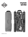 1
1
-
 2
2
-
 3
3
-
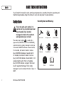 4
4
-
 5
5
-
 6
6
-
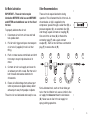 7
7
-
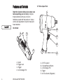 8
8
-
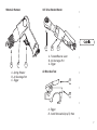 9
9
-
 10
10
-
 11
11
-
 12
12
-
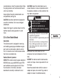 13
13
-
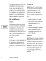 14
14
-
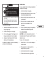 15
15
-
 16
16
-
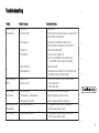 17
17
-
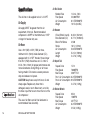 18
18
-
 19
19
-
 20
20
-
 21
21
-
 22
22
-
 23
23
-
 24
24
-
 25
25
-
 26
26
-
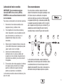 27
27
-
 28
28
-
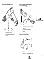 29
29
-
 30
30
-
 31
31
-
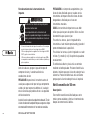 32
32
-
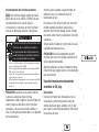 33
33
-
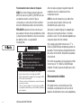 34
34
-
 35
35
-
 36
36
-
 37
37
-
 38
38
-
 39
39
-
 40
40
-
 41
41
-
 42
42
-
 43
43
-
 44
44


Simplicity 074003-0 Manual de usuario
- Categoría
- Herramientas eléctricas
- Tipo
- Manual de usuario
en otros idiomas
- English: Simplicity 074003-0 User manual