
1
Impecca Portable Air Conditioner
Users Manual
Models:
IPAC-12KS—12,000 BTU Cooling
IPAH-12KS—12,000 BTU Cooling and Heat Pump
IPAC-14KS—14,000 BTU Cooling
IPAH-14KS—14,000 BTU Cooling and Heat Pump

Table of Contents:
– Introduction ..................................................................................... p.1
– Safety Precautions ................................................................................ p.1
– What’s In The Box ................................................................................. p.2
– Installation Accessory Kit Items ................................................................... p.2
– Specications & Warnings ........................................................................ p.3
– Environmental Operating Conditions ............................................................. p.3
– Device parts identication ........................................................................ p.4
– Installation Instructions ........................................................................... p.5
– Energy Conservation Tips ......................................................................... p.6
– Operating Panel Overview ........................................................................ p.8
– Operating Instructions ........................................................................... p.9
– Additional Features ..............................................................................p.10
– Basic Error Codes & Solutions ....................................................................p.10
– Troubleshooting ................................................................................p.11
– Contact Support ................................................................................p.11
– Care instructions ................................................................................p.12
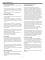
Regulatory Warnings:
DISPOSAL:
Do not dispose this product as unsorted municipal waste. Collection of such waste separately for special
treatment is necessary.
It is prohibited to dispose of this appliance in domestic household waste.
For disposal, there are several possibilities:
A) The municipality has established collection systems, where electronic waste can be disposed of at
least free of charge to the user.
B) When buying a new product, the retailer will take back the old product at least free of charge.
C) The manufacturer will take back the old appliance for disposal at least free of charge to the user.
D) As old products contain valuable resources, they can be sold to scrap metal dealers.
Wild disposal of waste in forests and landscapes endangers your health when hazardous substances leak
into ground-water and nd their way into the food chain.
CAUTION:
• This appliance is not intended for use by persons (including children) with reduced physical, sensory or
mental capabilities, or lack of experience and knowledge, unless they have been given supervision or
instruction concerning use of the appliance by a person responsible for their safety.
• Children should be supervised to ensure that they do not play with the appliance.

1
INTRODUCTION:
Congratulations on your purchase of an IMPECCA™ Electronic Controlled Portable Air Conditioner. Before
using this product, it is recommended that you familiarize yourself with the features, functions, and opera-
ting procedures described in this manual. Inside you will nd many helpful hints on how to use and maintain
your air conditioner properly. Just a little preventive care on your part can save you a great deal of time and
money over the lifespan of your air conditioner. You will nd many answers to common problems in the
chart of troubleshooting tips.
FEATURES AT A GLANCE:
• Quiet Operation
• Energy Saver Function
• Sleep mode
• Remote Control with LED
• Eco-Friendly Refrigerant
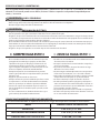
SAFETY PRECAUTIONS:
To prevent injury and/or property damage, please familiarize yourself with the following instructions
and safety precautions. Failure to comply with the instructions and cautions mentioned in this manual may
cause harm or damage. The seriousness is classied by the following indications:
IMPORTANT:
• Always contact an authorized service technician for repair or maintenance of this unit.
• This air conditioner is not intended for use by young children or elderly persons without supervision.
• Young children should be advised not to operate the air conditioner.
• If the power cord is to be replaced, replacement work should only be performed by certied or autho-
rized technicians.
• All electrical work must be performed in accordance with the national wiring standards and should only
be performed by authorized personnel.
NOTE: Due to slight modications in production, the instructions, features, and/or descriptions found in this
manual might vary slightly from your product.
SAVE TIME AND MONEY!
If you review our chart of Troubleshooting Tips rst, you may not need to call for service at all.
⚠ WARNING This symbol indicates the possibility of serious injury or death.
⚠ CAUTION This symbol indicates the possibility of injury and/or damage to property.
⊘
Never do this.
⍟
Always do this.

2
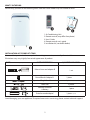
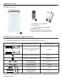
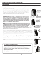
WHAT’S IN THE BOX:
Please verify your box for the following items. Note that some models may not include all items.
1. Air Conditioning Unit
2. Remote control (may di er from photo)
3. User’s Guide
4. Remote control user’s guide
5. Installation kit (see details below)
❶
❸
&
❹
❷
INSTALLATION ACCESSORY KIT ITEMS:
Your model may not include some optional mounting accessories, as noted by the asterisk *.
Illustrations may vary slightly from actual appearance of product.
PART (for illustration only, may not be identical) PART DESCRIPTION: QUANTITY INCLUDED:
Exhaust hose and adapter B
1 set
Round Mouth Adapter B 1 piece
Expansion Plug & Wood Screw*
4 pieces (optional)
Foam Seal 3 pieces
Remote Controller
& Battery
1 piece
Drain hose and adapter* 1 piece (optional)
Avoid damaging your new appliance! If required accessories are missing, please contact technical support.
F

SPECIFICATIONS & WARNINGS:
Carefully review all of these specications and warnings BEFORE operating your air conditioner unit. Failure
to do so may cause damage, injury, or bodily harm including permanent disability and/or death.
WARNING
FOR YOUR SAFETY
• Do not store or use gasoline or other ammable vapors/liquids in the vicinity of this or any other appliance.
• Avoid re hazard or electric shock. Do not use an extension cord or an adaptor plug.
Do not remove any prong from the power cord.
WARNING
ELECTRICAL INFORMATION
• Be sure your electrical wiring is adequate for the model you have chosen. This information can be found
on the serial plate, which is located on the side of the cabinet and behind the grille.
• Be sure the air conditioner is properly grounded. To minimize shock and re hazards, proper grounding
is important. The power cord is equipped with a three-prong grounding plug for protection against
shock hazards.
• Your air conditioner must be connected to a properly grounded wall receptacle. If the wall receptacle
you intend to use is not adequately grounded or protected by a time delay fuse or circuit breaker, have a
qualied electrician install the proper receptacle.
• Ensure the receptacle is accessible after the unit installation.
ENVIRONMENTAL OPERATING CONDITIONS:
The air conditioner must be operated within the temperature ranges indicated below:
MODE ROOM TEMPERATURE
COOLING
62°F to 95°F | 17°C to 35°C
FAN OR DEHUMIDIFYING
55°F to 95°F | 13°C to 35°C
HEATING
(heat pump models)
62°F to 88°F | 5°C to 30°C
⍟ ALWAYS DO THIS! ⍟
•
Your air conditioner should be used in such a way that it is
protected from moisture: e.g. condensation, splashed
water, etc. Do not place or store your air conditioner where
it can fall or be pulled into water or any other liquid. If unit
is in contact with liquid, unplug immediately.
• Always transport your air conditioner in a vertical position
and stand on a stable, level surface during use.
• Turn o the product when not in use.
• Always contact a qualied person to carry out repairs. If
the supply cord is damaged, it must be repaired by a qual-
ied repairer.
• Keep an air path of at least 12” (30cm) all around the unit
from walls, furniture and curtains.
• If the air conditioner is knocked over during use, turn o
the unit and unplug immediately.
⊘ NEVER DO THIS! ⊘
• Do not operate your air conditioner in a wet room such as
a bathroom or laundry room.
• Do not touch the unit with wet or damp hands or when
barefoot.
• Do not press the buttons on the control panel with any-
thing other than your ngers.
• Do not remove any xed covers. Never use this appliance
if it is not working properly, or if it has been dropped or
damaged.
• Never use the plug to start and stop the unit. Always use
the switch on the control panel.
• Do not cover or obstruct the inlet or outlet grille.
• Do not use hazardous chemicals to clean or come into
contact with the unit. Do not use the unit in the presence
of ammable substances or vapors such as alcohol, insecti-
cides, petrol, etc.
• Do not allow children to operate the unit unsupervised.
• Do not use this product for functions other than those
described in this instruction manual.

4
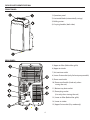
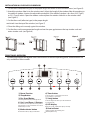
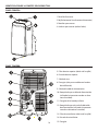
DevICe PARTs IDenTIFICATIon:
FRonT PAnel:
ReAR PAnel:
1) Operation panel
2)
Horizontal blade (automatically swings)
3) Rolling casters
4) Carrying handles (both sides)
5) Upper air lter (Behind the grille)
6) Upper air intake
7)
Air/moisture outlet
8)
Lower Drain outlet (only for heat pump models)
9) Power cord outlet
10) Power cord buckle (Used only when
storing the unit)
11) Bottom tray drain outlet
12) Power plug socket
(Use only when storing the unit)
13) Lower air lter (Behind the grille)
14) Lower air intake
15)
Upper Drain outlet (Dry mode only)

5
INSTALLATION INSTRUCTIONS:
Carefully review all of these instructions BEFORE proceeding to install and operate your air conditioner unit.
Failure to do so may cause damage, injury, or bodily harm including permanent disability and/or death.
LOCATION:
• The air conditioner should be placed on a rm foundation to minimize noise and virbration. For safe and
secure positioning, place the unit on a smooth, level oor strong enough to support the unit.
• The unit has casters to aid placement, but it should only be rolled on smooth, at surfaces. Use caution
when rolling on carpet surfaces. Do not attempt to roll the unit over objects.
• The unit must be placed within reach of a properly rated grounded socket.
• Never place any obstacles around the air inlet or outlet of the unit.
• Allow 1 to 3 feet (30cm to 100cm) of space from the wall with for ecient air-conditioning and prevent
overheating.
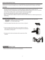
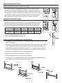
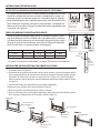
EXHAUST HOSE INSTALLATION:
The exhaust hose and adaptor must be installed or removed in accordance with the usage mode.
INSTALLED—Cooling, heat pump, or auto mode
REMOVED— Fan or dehumidify mode
1. Install the adapter B onto the exhaust hose as shown in Figure A.
2. Reseat the hook of the Exhaust hose into the hole seat of the air
outlet and slide down the Exhaust hose along the arrow direction
for installation. (see Figure B)
CAUTION
EXHAUST PORT
Make sure that there are no obstacles within 18” or 50cm around the exhaust
outlet in order for the exhaust system to work properly.
Figure A
Figure B
Figure C
3.
Be sure not to let the hose develop a kink or operation will be
impeded.

6
INSTALLATION INSTRUCTIONS CONTINUED:
SAVE $$$ & CONSERVE ENERGY
• Use the unit in the recommended room size.
• Locate the unit where furniture cannot obstruct the air ow.
• Keep blinds/curtains closed during the sunniest part of the day.
• Keep the lters clean.
• Keep doors and windows closed to keep cool air in and warm air out
WATER DRAINAGE
Depending on your model, your A/C unit is equipped with two or three water outlets.
As shown in the diagram above, the three are:
P Upper drain outlet (all models).
I The lower drain outlet (IPAH – heat pump models only).
L Bottom tray drain outlet (all models).
All units are partially self-evaporative in cooling mode and do their best to evaporate
all the water through the exhaust hose. In dehumidification mode, however, water
will collect. There are also climates where excess condensation may collect and need
to be drained in cooling and heat pump modes. This section address these
situations:
COOLING MODE
You can test to see if and how often your climate requires drainage by just letting the
unit run. If it stops with a P
1 error, then water has collected and should be evacuated
by removing the bottom tray drain plug
L. You can just leave your unit next to a
drain or attach a hose to the Bottom Tray drain outlet and lead to a drain, if this is
necessary.
DEHUMIDIFYING (DRY) MODE
Water will collect and must be drained. There are two methods you can use.
Option 1 (Figure F): Remove the upper drain plug P from the back of the unit. Install
the drain connector (5/8" universal female mender) with 3/4” hose (available in local
hardware stores). Place the open end of the hose adaptor directly over the drain area
in your basement floor.
Option 2 (Figure J): Wait until the unit stops with a P
1 error and drain the water
through the bottom tray drain outlet L.
HEAT PUMP MODE
If you have an IPAH model, it is equipped with a pump and drainage outlet. There are
two methods you can use to drain any excess water, if necessary:
Option 1 (Figure G): Remove the lower drain plug I from the back of the unit. Install
the drain connector (5/8" universal female mender) with 3/4” hose (available in local
hardware stores). Place the open end of the hose adaptor directly over the drain area
in your basement floor. Note that since this outlet has a pump attached, you can also
run this hose vertically – up to 2.6 feet, but be sure that it eventually bends
downwards again so that water doesn’t return to the unit. See Figure H for the
correct method and Figure I for the incorrect method.
Option 2 (Figure J): Wait until the unit stops with a P
1 error and drain the water
through the bottom tray drain outlet L.
Notes:
All drain outlets include the option for using a non-threaded type connector.
Avoid any kinks in any hoses that may stop the water flow.

7
INSTALLATION INSTRUCTIONS:
WINDOW SLIDER KIT INSTALLATION OPTIONAL:
Your window slider kit has been designed to t most standard vertical
and horizontal window applications, However, it may be necessary for
you to improvise/modify some aspects of the installation procedures for
certain types of windows. Please refer to Figure K & Figure L for minimum
and maximum window openings. Window slider kit can be fixed with a
bolt (see Figure M). Note that the shape of your adapter may differ.
WINDOW SLIDER SIZING CHART
Use the following chart to determine minimum and maximum gap sizes
for exhaust installation within windows. If the window opening is shorter
than the noted minimum length of the window slider kit, cut the slider
kit to the appropriate length. NEVER cut the kit shorter than the hole.
A a B b
Type I 67.5 cm 2.22 ft. 123 cm 4.04 ft
Type II 56.2 cm 1.84 ft. 98.2 cm 3.22 ft
• A columns correpsond to minimum size
• B columns correspond to maximum size
INSTALLATION IN A DOUBLEHUNG SASH WINDOW:
1. Cut the foam seal (adhesive type) to the proper length and attach it to the window
stool. (see Figure N)
2. Attach the window slider kit to the window stool. Adjust the length of the window
slider kit according to the width of window, shorten the adjustable window kit
if the width of window is less than 26.5 (Type I) or 22.1 (Type II) inches Open the
window sash and place the window slider kit on the window stool. (see Figure O)
3. Cut the foam seal(adhesive type) to the proper length
and attach it on the top of the window. (see Figure P)
4. Close the window sash securely against the window.
5. Cut the foam seal to an appropriate length and seal the open gap between the
top window sash and outer window sash. (see Figure Q)

8
INSTALLATION IN A SLIDING SASH WINDOW:
1. Cut the foam seal(adhesive type) to the proper length and attach it to the window frame. (see Figure R)
2. Attach the window slider kit to the window stool. Adjust the length of the window slider kit according to
the width of window, shorten the adjustable window kit if the width of window is less than 26.5 (Type I)
or 22.1 (Type II) inches. Open the window sash and place the window slider kit on the window stool.
(see Figure S)
3. Cut the foam seal (adhesive type) to the proper length
and attach it on the top of the window. (see Figure T)
4. Close the sliding sash securely against the window.
5. Cut the foam seal to an appropriate length and sea the open gap between the top window sash and
outer window sash. (see Figure U)
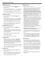
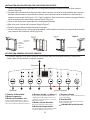
FRONT PANEL OVERVIEW:
The following diagram and legend shows the functions of the front operating panel. Some functions are
only available on select models.
1) Power Function
2) Sleep button
3)
Fan Speed Button
Control fan speed between low, medium, high and auto.
4)
Up (+) and Down (–)
Buttons
Use to increase or decrease temperature. To change between
degree display in F or C, press and hold both + and – buttons
simultaneously for 3 seconds.
6) Timer button
Activate the unit for a set period of time, increased and
decreased using the + and – buttons
7) Swing button
Activate the swing feature and/or stop the directional blade in
its position manually.
8) LED display
Displays the set temp., in fan/dry mode displays actual temp.
9
5) Mode selector button
Alternate between Auto, Cool, Dry, Fan & Heat modes
9
)
Heat indicator
Lights up to indicate unit in Heating mode
(Heat Pump Models only)
(Optional)

9
OPERATING INSTRUCTIONS:
COOLING operation
•
Press the “MODE” button until the indicator
light comes on.
•
Press the ADJUST buttons “+” or “ - “ to select your
desired room temperature. The temperature can
be set within a range of 62°F-88°F (17°C-30°C).
• Press the “FAN SPEED” button to choose fan speed.
HEATING operation
•
Press the “MODE” button until the indicator
light comes on.
•
Press the ADJUST buttons “+” or “ - “ to select your
desired room temperature. The temperature can
be set within a range of 62°F-88°F (17°C-30°C).
• Press the “FAN SPEED” button to choose the fan
speed. For some models, the fan speed can not
be adjusted under HEAT mode.
•
Press the “MODE” button until the indicator
light comes on.
• Under this mode, you cannot select a fan speed
or adjust the temperature. The fan motor oper-
ates at LOW speed.
• Keep windows and doors closed for the best
dehumidifying eect.
• Do not connect the duct to window.
AUTO operation
•
When you set the air conditioner to mode, it
will automatically select cooling, heating(cool-
ing only models without), or fan only operation
depending
on what temperature you have select-
ed and the room t
emperature.
•
The air conditioner will control room temperature
and fan speed automatically based on the the
temperature point set by you.
FAN operation
•
Press the “MODE” button until the indicator
light comes on.
• Press the “FAN SPEED” button to choose the fan
speed. The temperature cannot be adjusted.
• Do not connect the duct to window.
TIMER operation
• When the unit is on, press the
•
When the unit is on, pressing the TIMER button
will initiate the Auto-off stop program. The
TIMER OFF Indicator light will illuminate. Press
the UP or DOWN button to deselect the desired
time (in hours) until the unit will turn off. Press
the TIMER button again within 5 seconds and the
TIMER ON indicator light will illuminate. Press or
hold the UP or DOWN button to select the
desired time from now you want the unit to turn
on again.
•
When the unit is off, press the TIMER button to
initiate the Auto-on start program. Press it again
within 5 seconds to set the time for the Auto-off
stop program. Use the UP and DOWN buttons
to change the time accordingly (in hours).
•
The display will automatically revert to the
previous temperature setting if there are no
modifications within a five second period.
•
Malfunction error codes (E1, E2, E3 or E4) will also
cancel any Auto-Start/Stop programs.
•
Turning the unit ON or OFF at any time or
adjusting the timer setting to 0.0 will cancel the
Auto Start/ Stop timer program.
•
Note that the time function starts out in half-
hour increments (.5, 1, 1.5) until it reaches 10
hours.
SLEEP operation
•
Press this button, the selected temperature
will increase (cooling) or decrease (heating) by
2°F(1°C) after 30 minutes. The temperature will
then increase (cooling) or decrease (heating) by
another 2°F(1°C) after an additional 30 minutes.
• The new temperature will be maintained for 7
hours before it returns to the originally select-
ed temperature. This ends Sleep mode and the
unit will continue to operate as originally pro-
grammed.
• NOTE: This feature is unavailabe under FAN or
DRY mode.
DEHUMIDIFYING operation
•
The timer begins from the present moment,
so if it is presently midnight and you set the
OFF time for 6 hours and the on time for 12,
it will go off at 6 AM and on again at 12 PM.

10
ADDITIONAL FEATURES:
Auto Restart
• If the unit breaks ounexpectedly due to the
power cut, it will restart with the previous func-
tion setting automatically when the power
resumes.
S
elf Protection
• After the unit has stopped, it can not restart oper-
ation for 3 minutes following shut down. This is
to protect the unit. Operation will automatically
resume after 3 minutes has elapsed.
Air ow direction adjustment
• The directional blade can be adjusted automati-
cally.
• Adjust the air ow direction automatically
• When the Power is ON, the blade opens fully.
• Press the SWING button on the panel or remote
controller to initiate the Auto swing feature.
• The blade willl swing up and down automatically.
•
Press the SWING button again to block the blade
in a xed direction
.
NOTE: Please do not adjust the blade manually
.
BASIC ERROR CODES:
Use the following guidelines to understand and troubleshoot common error codes.
E
1: Room temperature sensor error.
• Unplug the unit and plug it back in.
• If error repeats, call for service.
E2: Evaporator temperature sensor error
• Unplug the unit and plug it back in.
• If error repeats, call for service.
E3
: Condenser temperature sensor error
• Unplug the unit and plug it back in.
• If error repeats, call for service.
E4: Display panel communication error
• Unplug the unit and plug it back in.
• If error repeats, call for service.
P
1: Bottom condensation tray is full
• Connect the drain hose and drain the collected water away.
• Note that frequent draining may be required, especially in humid climates
and during seasonal weather changes.
• If protection repeats after draining, call for service.

11
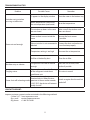
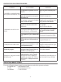
TROUBLESHOOTING TIPS:
Problem Possible Causes Remedies
Unit does not start when
pressing on/o button
P 1
appears in the display window
Drain the water in the bottom tray
Room temperature is lower than
the set temperature (cool mode)
Reset the temperature
Room not cool enough
The windows or doors in the room
are not closed
Make sure all the windows and
doors are closed
There are heat sources inside the
room
Remove the heat sources
if possible
Exhaust air duct is not connected or
blocked
Connect the duct and make sure
it can function properly
Temperature setting is too high Decrease the set temperature
Air lter is blocked by dust Clean the air lter
Machine noisy or vibrates
The ground is not level or not at
enough
Place the unit on a at, level
surface if possible
Gurgling noises
The sound comes from the owing
of the refrigerant inside the air
conditioner unit
This noise is normal
Power shuts o in heating mode
The automatic overheat protection
function kicks in. When the tem-
perature at the aur outlet exceeds
158°F/70°C, the device will automa-
tically shut o.
Switch on again after the unit has
cooled o.
Impecca customer support can be contacted in the following methods:
• Online 24/7: www.impeccausa.com
• By e-mail: ser[email protected]
•
By phone: +1 866-954-4440
CONTACT SUPPORT:

12
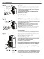
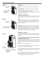
CARE & MAINTENANCE:
IMPORTANT:
1) Be sure to unplug the unit before cleaning or servicing.
2) Do not use gasoline, thinner or other chemicals to clean
the unit.
3) Do not wash the unit directly under a tap or using a hose.
It may cause electrical danger.
4) If the power cord is damaged, it should be repaired by
manufacture or its agency.
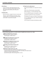
AIR FILTER CLEANING:
Clean the air lter at least once every two weeks to prevent
inferior fan operation because of dust.
REMOVAL: This unit has two lters. Take the upper lter out
along the the arr
ow direction (Figure 1), then take the lter
down. Remove the lower lter by loosening the screw, taking
out the lter as shown in (Figure 1).
CLEANING: Wash the air filter by immersing it gently in
warm water (about 104°F(40°C) with a neutral detergent.
Rinse the filter and dry it in a shady place.
MOUNTING: Install the upper air lter after cleaning , and
install the lower lter by using the screw (see Figure 2).
UNIT ENCLOSURE:
Use a lint-free cloth soaked with neutral detergent to clean
the unit enclosure. Finish by wiping with a dry clean cloth.
BEFORE STORING OR NOT USING A UNIT
FOR LONG PERIODS OF TIME:
Remove the rubber plug at the back of the unit and attach a
hose to drain outlet. Place the open end of the hose directly
over the drain area in your basement oor.
(see Figures F, G, H and I on page 6)
Remove the plug from the bottom drain outlet, all the water
in the bottom tray would drain out (see Figure J on page 6)
Keep the appliance running on FAN mode for half a day in
a warm room to dry the appliance inside and prevent mold
from forming.
Stop the appliance and unplug it, wrapped the cord and bun-
dle it with the tape (Figure 3). Clean the air lter and reinstall
it (see above). Remove batteries from the remote controller.

13
Aire Acondicionado Portátil Impecca
Manual de Usuario
IPAC-12K—12,000 BTU portable A/C
IPAH-12K—12,000 BTU H&C portable A/C
IPAC-14K—14,000 BTU portable A/C
IPAH-14K—14,000 BTU H&C portable A/C

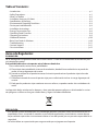
Table of Contents:
– Introduction ..................................................................................... p.1
– Safety Precautions ................................................................................ p.1
– What’s In The Box ................................................................................. p.2
– Installation Accessory Kit Items ................................................................... p.2
– Specications & Warnings ........................................................................ p.3
– Environmental Operating Conditions ............................................................. p.3
– Device parts identication ........................................................................ p.4
– Installation Instructions ........................................................................... p.5
– Energy Conservation Tips ......................................................................... p.6
– Operating Panel Overview ........................................................................ p.8
– Operating Instructions ........................................................................... p.9
– Additional Features ..............................................................................p.10
– Basic Error Codes & Solutions ....................................................................p.10
– Troubleshooting ................................................................................p.11
– Contact Support ................................................................................p.11
– Care instructions ................................................................................p.12
Avisos de Regulación:
ELIMINACIÓN:
No se deshaga de este producto como basura local común. Es necesaria la recolección de esta basura para
un tratamiento especial.
Está prohibido desechar este aparato entre la basura doméstica.
Para su eliminación, existen varias posibilidades:
A) El municipio tiene establecido sistemas de recolección, donde la basura electrónica se puede de-
sechar sin cargo alguno para el usuario.
B) Cuando se compra de un producto nuevo, el minorista puede retirar el producto viejo incluso de
forma gratuita.
C) El fabricante tomará de nuevo el aparato viejo para su eliminación incluso sin cargo alguno para el
usuario.
D) Dado que los productos viejos contienen recursos valiosos, se pueden vender a los recicladores de
metal.
La disposición de los residuos en los bosques y áreas naturales pone en peligro su salud cuando las sustan-
cias peligrosas se ltran en las aguas subterráneas, y llegan a la cadena alimenticia.
PRECAUCIÓN:
• Este aparato no está destinado para ser utilizado por personas (incluidos niños) con disminución en sus
capacidades físicas, sensoriales o mentales; o con falta de experiencia y conocimiento, a menos de que
hayan recibido supervisión o instrucciones relativas al uso del aparato por una persona responsable de su
seguridad.
• Los niños deben ser supervisados para asegurarse de que no jueguen con el aparato.

15
INTRODUCCIÓN:
Felicitaciones por su compra de un Aire Acondicionado Portátil Controlado Electrónicamente Impecca™.
Antes de utilizar este producto, se recomienda que se familiarice con las características, funciones y procedi-
mientos operativos descritos en este manual. En su interior encontrará muchos consejos útiles sobre cómo
utilizar y conservar su aire acondicionado. Un poco de cuidado preventivo de su parte puede ahorrarle mu-
cho tiempo y dinero durante la vida útil de su aire acondicionado. Encontrará muchas respuestas a proble-
mas comunes en la tabla de consejos para la solución de problemas.
AHORRE TIEMPO Y DINERO!
Si primero revisa nuestro cuadro de consejos para solución de problemas, es posible que no necesite
llamar al servicio técnico.
VISTAZO A LAS CARACTERÍSTICAS:
• Funcionamiento silencioso • Filtro de Iones (modelos elegidos)
• Función de Ahorro de Energía • Modo de suspensión
• Control Remoto con LED • Refrigerante Amigable con el Medio Ambiente
• Sensor Remoto de Temperatura Personal (en algunos modelos)
MEDIDAS DE SEGURIDAD:
Para evitar lesiones y / o daños a la propiedad, por favor familiarícese con las siguientes instrucciones
y precauciones de seguridad. El incumplimiento de las instrucciones y precauciones mencionadas en este
manual puede causar lesiones o daños. Su gravedad se clasica mediante las siguientes indicaciones:
⚠
ADVERTENCIA
Este símbolo indica la posibilidad de lesiones graves o la muerte.
⚠
PRECAUCIÓN
Este símbolo indica la posibilidad de lesiones y / o daños a la propiedad.
⊘
Nunca haga esto.
⍟
Siempre haga esto.
IMPORTANTE:
• Siempre contacte a un técnico de servicio autorizado para la reparación o mantenimiento de esta uni-
dad.
• Este aire acondicionado no está diseñado para ser utilizado por niños o adultos mayores sin supervisión.
• Se debe advertir a los niños pequeños sobre no utilizar el aire acondicionado.
• Si el cable de alimentación debe ser sustituido, el trabajo de sustitución sólo debe ser realizado por técni-
cos certicados o autorizados.
• Todos los trabajos eléctricos deben ser realizados de acuerdo con las normas nacionales de cableado y
sólo debe ser realizado por personal autorizado.
NOTA: Debido a ligeras modicaciones en la producción, las instrucciones, características y / o descripciones
que se encuentran en este manual pueden variar ligeramente a las de su producto.

16
❶
❸
&
❹
❷
QUÉ HAY EN LA CAJA?:
Por favor revise en su caja los siguientes elementos. Tenga en cuenta que algunos modelos pueden no in-
cluir todos los elementos.
1. Unidad de Aire Acondicionado
2. Control remoto
(puede diferir al de la fotografía)
3. Manual de Usuario
4. Manual de Usuario del Control Remoto
5. Kit de instalación (ver detalles más abajo)
ARTÍCULOS DEL KIT DE INSTALACIÓN DE ACCESORIOS:
Su modelo puede no incluir algunos de los accesorios de montaje opcionales, como se indica por el símbo-
lo*. Las ilustraciones pueden variar ligeramente de la apariencia real del producto.
PARTE
(Sólo como ejemplo, puede no ser idéntica)
DESCRIPCIÓN DE LA PARTE : CANTIDAD INCLUIDA :
Manguera de escape y adaptador
A –O– adaptador B
1 conjunto
Adaptador de Escape de Pared A* 1 unidad (opcional)
Adaptador de boca redonda B* 1 unidad (opcional)
Hoyo de Expansión
& Tornillo de Madera*
4 unidads (opcional)
Sellante Sintético 3 unidads
Control Remoto Y Pila 1 unidad
Manguera de drenaje
y Adaptador*
1 unidad (opcional)
¡Evite dañar su aparato nuevo! Si los accesorios necesarios no están incluidos, por favor póngase en contacto
con soporte técnico.

ESPECIFICACIONES Y ADVERTENCIAS:
Revise cuidadosamente todas estas especicaciones y advertencias ANTES de usar su unidad de aire acondi-
cionado. El no hacerlo puede causar daños, lesiones o daños corporales incluyendo discapacidad perma-
nente y / o muerte.
ADVERTENCIA
POR SU SEGURIDAD
• No guarde ni use gasolina u otros líquidos o vapores / líquidos en las proximidades de este o cualquier otro electrodoméstico.
• Evite el riesgo de incendio o descarga eléctrica. No utilice un cable de extensión ni un adaptador.
• No retire ninguna clavija del cable de alimentación.
ADVERTENCIA
INFORMACIÓN ELÉCTRICA
• Asegúrese de que el cableado eléctrico sea adecuado para el modelo que usted ha elegido. Esta información se puede encon-
trar en la placa de serie, que se encuentra al lado de la carcasa y detrás de la rejilla.
• Asegúrese de que el aire acondicionado esté correctamente conectado a tierra. Para minimizar los riesgos de choque eléctri-
co e incendio, es importante una conexión a tierra adecuada. El cable de alimentación está equipado con un enchufe de tres
clavijas para protección contra posibles descargas eléctricas.
• El aire acondicionado debe estar conectado a un enchufe de pared con polo a tierra adecuado. Si el tomacorriente que pre-
tende utilizar no está conectado adecuadamente a tierra o protegido por un fusible de retardo o un interruptor de circuito,
haga que un electricista calicado instale el tomacorriente adecuado.
• Asegúrese de que el receptáculo sea accesible después de la instalación de la unidad.
CONDICIONES AMBIENTALES DE FUNCIONAMIENTO:
El aire acondicionado debe ser operado dentro de los rangos de temperatura indicados a continuación:
MODO TEMPERATURA DE LA HABITACIÓN
REFRESCAR F: 62° a 95° | C: 17° a 35°
VENTILADOR O DESHUMIDIFICADOR F: 55° a 95° | C: 13° a 35°
CALEFACCIÓN
(modelos con bomba de calor) F: 62° a 88° | C: 5° a 30°
⍟ SIEMPRE HAGA ESTO! ⍟
• El aire acondicionado debe usarse de tal manera que esté
protegido de la humedad, por ejemplo, condensación,
salpicaduras de agua, etc. No ponga ni almacene el aire
acondicionado donde se pueda caer o ser empujado al
agua o cualquier otro líquido. Si la unidad se pone en con-
tacto con el líquido, desenchufe inmediatamente.
• Siempre transporte el aire acondicionado en posición
vertical y apoyado sobre una supercie estable y nivelada
durante su uso.
• Apague el aparato cuando no esté en uso.
• Siempre contacte una persona calicada para llevar a cabo
las reparaciones. Si el cable de alimentación está dañado,
debe ser reparado por un taller de reparación calicado.
• Conserve un espacio de ventilación de por lo menos 12”
(30 cm) alrededor de la unidad respecto a paredes, mueb-
les y cortinas.
• Si el aire acondicionado es derribado durante el uso, apa-
gue la unidad y desenchufe inmediatamente.
⊘ NUNCA HAGA ESTO! ⊘
• No utilice su aire acondicionado en una habitación húme-
da como un baño o lavadero.
• No toque la unidad con las manos húmedas o mojadas, o
con los pies descalzos.
• No presione los botones del panel de control con algo
diferente a los sean los dedos.
• No retire ninguna cubierta ja. Nunca use este aparato si
no funciona correctamente, o si se ha caído o dañado.
• Nunca utilice el enchufe para encender y apagar la unidad.
Siempre utilice el interruptor en el panel de control.
• No cubra ni obstruya la rejilla de entrada o de salida.
• No utilice productos químicos peligrosos para limpiar o
entrar en contacto con la unidad. No utilice el aparato en
presencia de sustancias o vapores inamables como alco-
hol, insecticidas, gasolina, etcétera.
• No permita que los niños usen la unidad sin supervisión.
• No utilice este aparato para funciones distintas a las descri-
tas en este manual de instrucciones.

18
IDenTIFICACIÓn De lAs PARTes Del DIsPosITIvo:
PAnel FRonTAl:
PAnel TRAseRo:
1. Panel de funciones
2. Rejilla horizontal (oscila automáticamente)
3. Rueditas para mover
4. Asideras para mover (ambos lados)
5. Filtro de aire superior (detrás de la rejilla)
6. Entrada de aire superior
7. Salida de aire
8. Desagüe (solo para modelo con bomba
de calefacción)
9. Salida del cable de alimentación
10. Receptáculo para cable de alimentación
(utilizado únicamente cuando se alma-
cena la unidad)
11. Desagüe de la bandeja inferior
12. Receptáculo para el enchufe del cable
de alimentación (utilizado únicamente
cuando se almacena la unidad)
13. Filtro de aire inferior (detrás de la rejilla)
14. Entrada de aire inferior
15. Desagüe

19
INSTRUCCIONES DE INSTALACIÓN :
Revise cuidadosamente todas estas instrucciones ANTES de proceder a instalar y usar su aire acondicionado.
El no hacerlo puede causar daños, lesiones o daño corporal incluyendo la discapacidad permanente y / o
muerte.
UBICACIÓN :
• El aire acondicionado debe ser puesto sobre una base rme para minimizar el ruido y la vibración. Para
un posicionamiento seguro, ponga la unidad sobre una supercie lisa y plana lo sucientemente fuerte
como para soportar la unidad.
• La unidad dispone de ruedas para ayudar a su ubicación, pero debe rodarse en supercies lisas y planas.
Tenga cuidado al rodar sobre supercies de moqueta, tapetes o felpudos. No intente rodar la unidad
sobre objetos.
• La unidad debe estar al alcance de una toma de corriente adecuada con conexión a tierra.
• Nunca ponga obstáculos alrededor de la entrada o salida de aire de la unidad.
• Deje de 1 a 3 pies (30 cm a 100 cm) de espacio de la pared para un ujo de aire eciente y evitar el so-
brecalentamiento.
INSTALACIÓN DE LA MANGUERA DE ESCAPE :
La manguera de escape y el adaptador deben ser instalados o retirados de acuerdo con el modo de uso.
RETIRADA—calefacción (eléctrica), ventilador o el modo de des-humidicación
INSTALADA—enfriamiento, bomba de calor, o el modo automático
1. Instalar el adaptador B del escape para la ventana en la manguera de
escape como se muestra en la Fig. A o Fig. B. Consulte las páginas anteri-
ores para la instalación de kit de ventana.
2. Ponga la manguera de escape a lo largo contra el gancho de la abertura
de salida de aire y aplane el otro extremo (Figura C) para una instalación
rápida.
La manguera de escape puede ser instalada en la pared (aplicable a las
unidades sin adaptador A, tacos de expansión y accesorios de tornillos de
madera).
1. Prepare un agujero en la pared. Instale el adaptador A de Escape pared
en la pared (exterior) utilizando 4 tacos de expansión y tornillos de madera,
asegúrese de jar completamente (Ver Figura D).
2. Conecte la manguera de escape al adaptador A de pared del escape.
NOTA: Cubra el oricio con la tapa del adaptador cuando no esté en uso.
El conducto puede ser comprimido o extendido moderadamente de acuer-
do con las exigencias de la instalación, pero es deseable mantener la longi-
tud del conducto a un mínimo.
IMPORTANTE: NO CURVE NI DOBLE LA MANGUERA DE SALIDA (ver Fig. E).
CAUTION
SALIDA DEL ESCAPE
Asegúrese de que no hayan obstáculos en 18 “o 50 cm alrededor de la salida del
escape para que el sistema de escape funcione correctamente.
Adaptador A
Posición del plug
de expansión
Tapa del adaptador

20
INSTRUCCIONES DE INSTALACIÓN CONTINUACIÓN:
DRENAJE DE AGUA:
Ciertas funciones de su unidad de aire acondicionado crean condensación y debe evacuarse el agua acumulada. Por
favor, siga cuidadosamente estas instrucciones de acuerdo a su uso y las condiciones de uso.
MODO DE DES-HUMIDIFICACIÓN: Retire el tapón de drenaje de la parte posterior
de la unidad, instale el conector de drenaje (5/8 “ conector hembra universal) con
una manguera estándar de 3/4” (disponible en una ferretería local).Para los mod-
elos sin un conector de desagüe, simplemente conecte la manguera de drenaje
al agujero. Ponga que el extremo abierto del adaptador de la manguera directa-
mente sobre el área de drenaje en el piso del sótano (Ver gura F).
BOMBA DE CALOR: Retire el tapón de drenaje inferior en la parte posterior de la
unidad, instale el conector de drenaje (5/8” conector hembra universal) con una
manguera estándar de 3/4” (disponible en las ferreterías locales).Para los modelos
sin conector de drenaje, solo conecte la manguera de drenaje en la salida. Ponga
el extremo abierto del adaptador de la manguera directamente sobre el área de
drenaje en el piso del sótano. (Véase la Figura G).
NOTA: Asegúrese de que la manguera esté asegurada para que no haya fugas. Dirija
la manguera hacia el drenaje, asegurándose de que no existan dobleces que deten-
gan el ujo de agua. Ponga el extremo de la manguera en el desagüe y asegúrese
de que el extremo de la manguera apunta hacia abajo y deje que el agua uya
suavemente (Ver Figuras F, G y H).No levante la manguera de drenaje para evitar
que el agua drenada se devuelva (ver Figura I).
Cuando el nivel del agua de la bandeja inferior alcanza un nivel predeterminado, la unidad
emite un sonido 8 veces, el área de visualización digital muestra P1. En este momento, el pro-
ceso de aire acondicionado / des-humidicación se detendrá inmediatamente. Sin embargo,
el motor del ventilador continuará funcionando (esto es normal).
Cuidadosamente mueva la unidad a un lugar de desagüe, quite el tapón de drenaje inferior y
deje que el agua drene hacia afuera (ver Figura J). Vuelva a instalar el tapón de drenaje inferior
y reinicie la máquina hasta que el símbolo P1 desaparezca. Si el error se repite, llame al servi-
cio técnico.
NOTA: Asegúrese de volver a instalar el tapón de drenaje en el fondo antes de usar la unidad.
$ $ $ AHORRE Y CONSERVE ENERGÍA
• Utilice la unidad en una habitación con el tamaño recomendado.
• Ponga la unidad en donde los muebles no puedan obstruir el ujo de aire.
• Mantenga las persianas / cortinas cerradas durante la parte más soleada del día.
• Mantenga limpios los ltros.
• Mantenga las puertas y ventanas cerradas para mantener el aire frío adentro y el aire
caliente afuera.
Manguera
de drenaje
continuo
Adaptador de
la manguera
de desagüe
Remueva el tapón
del drenaje superior
Manguera
de drenaje
continuo
Adaptador de
la manguera
de desagüe
Remueva el
tapón del drenaje
inferior

21
INSTRUCCIONES DE INSTALACIÓN :
KIT DE INSTALACIÓN PARA VENTANA DESLIZANTE OPCIONAL:
Su kit para ventana deslizante ha sido diseñado para adaptarse a la may-
oría de los modelos de ventanas verticales y horizontales estándar, sin
embargo, puede ser necesario improvisar / modicar algunos aspectos
de los procedimientos de instalación para ciertos tipos de ventanas. Por
favor remítase a la Figura K y la Figura L para minimizar y maximizar las
aberturas de la ventana. El kit para ventana deslizante se puede jar con
un tornillo (ver Figura M).
TABLA DE MEDIDAS DE VENTANA DESLIZANTE
Utilice la siguiente tabla para determinar los tamaños mínimos y máxi-
mos de la abertura para la instalación de escape dentro de las ventanas.
Si la abertura de la ventana es más corta que la longitud mínima señala-
da en el kit para ventana deslizante, corte el kit a la longitud adecuada.
NUNCA corte el kit a un tamaño inferior al del agujero.
A a B b
Tipo I 67,5 cm 2.22 ft 123 cm 4,04 ft
Tipo II 56,2 cm 1,84 ft 98,2 cm 3,22 ft
• Las columnas A corresponden a la medida mínima • Las columnas B corresponden a la medida máxima •
INSTALACIÓN EN UNA VENTANA CON DOBLE GUILLOTINA :
1. Corte el sello de espuma (tipo adhesivo) en la longitud apropiada y adhiéralo a la base de
la ventana (Véase la Figura N).
2. Conecte el kit para ventana deslizante a la base de la ventana. Ajuste de la longitud del kit
para ventana deslizante de acuerdo con el ancho de la ventana, acorte el kit para ventana
ajustable si la anchura de la ventana es menor que 26,5 (Tipo I) o 22,1 (Tipo II) pulgadas.
Abra la ventana y ponga el kit para ventana deslizante sobre la base de la ventana. (Véase
la Figura O).
3. Corte el sello de espuma (tipo adhesivo) a la longitud apropiada
y fíjelo en la parte superior de la ventana (Véase la Figura P).
4. Cierre la hoja de la ventana rmemente contra la ventana.
5. Corte el sello de espuma a una longitud adecuada y selle la abertura entre la hoja superior
de la ventana y la hoja exterior de la ventana. (Véase la Figura Q).
Ventana
horizontal
Kit de ventana corrediza
Mínimo: A:cm (a:ft)
Máximo: B:cm (b:ft)
Kit de ventana corrediza
Mínimo: A:cm (a:ft)
Máximo: B:cm (b:ft)
Ventana
horizontal
Tornillo
Kit de
ventana
corrediza
Sello de espuma A
(tipo adhesivo)
Kit de ventana
Herramienta
de ventana
Herramienta
de ventana
Kit de ventana
Sello de espuma

22
1) Función de Encendido
2) Botón Suspensión
3) Botón de Ventilador / Ion*
Control de velocidad del ventilador entre bajo, medio, alto
y automático. Mantenga pulsado durante 3 segundos para
activar / desactivar la función de puricación del aire de iones.
4) Botones Arriba (+) y Abajo (-)
Usados para aumentar o disminuir la temperatura. Para
cambiar la visualización de los grados entre F o C, presione
y mantenga presionados ambos botones (+) y (-) al mismo
tiempo durante 3 segundos.
5) Botón selector de modo
Alterna entre los modos Auto, Cool, Dry, Fan Y Heat
6) Botón del temporizador
Activa la unidad durante un período de tiempo determinado,
se aumenta y se disminuye usando los botones + y -
7) Botón oscilación
Active la función de giro y / o detiene la rejilla direccional en su
posición de forma manual.
8) Pantalla LED
Muestra la temperatura establecida, en los modos Fan/ Dry
muestra la temperatura actual.
9)
Indicador del modo de calor
INSTALACIÓN EN UNA VENTANA CON GUILLOTINA DESLIZANTE :
1. Corte el sello de espuma (tipo adhesivo) a la longitud apropiada y conéctelo al marco de la ventana
(Véase la Figura R).
2. Conecte el kit para ventana deslizante a la base de la ventana. Ajuste de la longitud del kit para ventana
deslizante de acuerdo con el ancho de la ventana, acorte el kit de ventana deslizante si el ancho de la
ventana es menor que 26,5 (tipo I) o 22,1 (Tipo II) pulgadas. Abra la hoja de la ventana y ponga el kit para
ventana deslizante en la base de la ventana (Véase la Figura S).
3. Corte el sello de espuma (tipo adhesivo) a la longitud apropiada
y fíjelo en la parte superior de la ventana (Véase la Figura T).
4. Cierre la hoja corrediza rmemente contra la ventana.
5. Corte el sello de espuma a una longitud apropiada y selle la abertura entre la hoja superior de la ventana
y hoja exterior de la ventana (Véase la Figura U).
DESCRIPCIÓN GENERAL DEL PANEL FRONTAL:
El siguiente diagrama y los textos muestran las funciones del panel frontal de funciones. Algunas fun-
ciones sólo están disponibles en algunos modelos.
Sello de
espuma A
(tipo
adhesivo)
Panel de la
ventana
Sello de espuma
(ION es Opcional)
(Opcional)
(Opcional)

23
INSTRUCCIONES DE USO:
FUNCIÓN DE ENFRIAMIENTO
• Presione el botón “MODE” hasta que se encienda la luz
indicadora “COOL”.
• Presione los botones de AJUSTE “+” o “-” para seleccio-
nar la temperatura ambiente deseada. La temperatura
se puede ajustar dentro de un rango de 17 °C-30 °C/62
°F-88 °F.
• Presione el botón “FAN SPEED” para seleccionar la ve-
locidad del ventilador.
FUNCIÓN DE CALEFACCIÓN
• Presione el botón “MODE” hasta que se encienda la luz
indicadora “HEAT”.
• Presione los botones de AJUSTE “+” o “-” para seleccio-
nar la temperatura ambiente deseada. La temperatura
se puede ajustar dentro de un rango de 17 °C-30 °C/62
°F-88 °F.
• Presione el botón “FAN SPEED” para seleccionar la ve-
locidad del ventilador. En algunos modelos, la velocid-
ad del ventilador no se puede ajustar en el modo HEAT.
• Presione el botón “MODE” hasta que se encienda la luz
indicadora “DRY”.
• En este modo, no se puede seleccionar la velocidad del
ventilador o ajustar la temperatura. El motor del venti-
lador funciona a BAJA velocidad.
• Mantenga las ventanas y las puertas cerradas para un
mejor efecto de des-humidicación.
• No conecte el conducto a la ventana.
FUNCIÓN AUTO
• Cuando usted pone el aire acondicionado en modo
AUTO, se seleccionará automáticamente solo el fun-
cionamiento de enfriamiento, calefacción (sólo en los
modelos sin refrigeración), o ventilador dependiendo
de la temperatura seleccionada y la temperatura ambi-
ente.
• El aire acondicionado controlará automáticamente la
temperatura ambiente de la habitación manteniéndola
cercana a la programada por usted.
• En el modo AUTO, no se puede seleccionar la velocidad
del ventilador.
FUNCIÓN VENTILADOR
• Presione el botón “MODE” hasta que se encienda la luz
indicadora “FAN”.
• Presione el botón “FAN SPEED” para seleccionar la
velocidad del ventilador. La temperatura no puede
ajustarse.
• No conecte el conducto a la ventana.
FUNCIÓN TEMPORIZADOR
• Cuando la unidad esté encendida, presione el
• El Botón Timer iniciará el programa de Apagado-Au-
tomático, la luz indicadora TIMER OFF se enciende.
Presione el botón UP o DOWN para seleccionar la hora
deseada. Presione de nuevo el botón TIMER dentro
de un lapso de 5 segundos, el programa de Encendi-
do-Automático se inicia. Y la luz indicadora TIMER ON
se enciende. Presione el botón UP o DOWN para selec-
cionar la hora de inicio del Encendido-Automático.
• Cuando la unidad esté apagada, presione el botón TIM-
ER para iniciar el programa de Encendido-Automático,
presione dentro de un lapso de cinco segundos y se
iniciará el programa de Apagado-Automático.
• Presione o mantenga presionado el botón UP o DOWN
para cambiar la hora Automática en incrementos de 0,5
horas, hasta 10 horas y luego en intervalos de 1 hora
hasta 24 horas. El Control hará una cuenta regresiva del
tiempo restante hasta el inicio.
• El sistema automáticamente volverá a mostrar la
temperatura anterior elegida, si no se realiza ninguna
operación en un período de cinco segundos.
• ENCENDER o APAGAR la unidad en cualquier momento
o ajustar el temporizador a 0,0, cancelará el programa
del temporizador de Encendido/Apagado Automático.
• Cuando ocurra el mal funcionamiento (E1, E2, E3 o E4),
el programa temporizador de Encendido/Apagado
Automático también será cancelado.
FUNCIÓN SUSPENSIÓN
• Presione este botón, la temperatura seleccionada
aumentará (refrigeración) o disminuirá (calefacción) en
1 °C / 2 °F después de 30 minutos. Después la tem-
peratura se incrementará (enfriamiento) o disminuirá
(calefacción) en otro 1 °C / 2 °F después de 30 minutos
adicionales.
• La nueva temperatura se mantendrá durante 7 horas
antes de regresar a la temperatura seleccionada orig-
inalmente. Esto dará por terminado el modo SLEEP
(suspensión) y la unidad seguirá funcionando como se
había programado.
• NOTA: Esta función no está disponible bajo los modos
FAN o DRY.

24
CARACTERÍSTICAS ADICIONALES :
Reinicio Automático:
• Si la unidad se apaga de manera inesperada debido
al corte del suministro eléctrico, se reiniciará con la
función congurada previamente automáticamente
después de la restitución del ujo eléctrico.
Autoprotección:
• Después de que la unidad se haya detenido, no
puede reiniciar su funcionamiento durante 3 minutos
después de haberse apagado. Esto es para proteger
la unidad. El funcionamiento se reanudará automáti-
camente después de que hayan transcurrido los 3
minutos.
Ajuste de la dirección del ujo de aire:
• La rejilla direccional puede ser ajustada automática-
mente.
• Ajuste la dirección del ujo de aire automáticamente
• Cuando esté Encendido, la rejilla se abre completa-
mente.
• Presione el botón SWING en el panel o en el control
remoto para iniciar la función de oscilación automáti-
ca.
• La rejilla se moverá hacia arriba y hacia abajo de for-
ma automática.
• Presione el botón SWING para bloquear la rejilla en
una posición ja.
•
NOTA: Por favor no ajuste la rejilla manualmente.
CÓDIGOS DE ERRORES BÁSICOS:
Use las siguientes pautas para entender y solucionar los códigos de error comunes.
E1: Error en la temperatura ambiente.
• Desenchufe la unidad y vuelva a conectarla.
• Si se repite el error, llame al servicio técnico.
E2: Error en el sensor de temperatura del evaporador
• Desenchufe la unidad y vuelva a conectarla.
• Si se repite el error, llame al servicio técnico.
E4: Error en el visualizador del panel de comunicación
• Desenchufe la unidad y vuelva a conectarla.
• Si se repite el error, llame al servicio técnico.
P1: La bandeja inferior de condensación está llena
• Conecte la manguera de drenaje y drene el agua recogida.
• Tenga en cuenta que puede ser necesario el drenaje frecuente, especialmente en climas húmedos
y durante los cambios climáticos estacionales.
• Si se repite la alerta después del drenaje, llame al servicio técnico.

25
CONSEJOS PARA SOLUCIONAR PROBLEMAS :
Problema Causas Posibles Soluciones
La unidad no se enciende cuan-
do se presiona el botón on / o
P1 aparece en la pantalla de visua-
lización
Vacíe el agua en la bandeja infe-
rior
La temperatura ambiente es más
baja que la temperatura programa-
da (modo frío)
Cambie la temperatura
La habitación no enfría lo su-
ciente
Las ventanas y puertas de la habita-
ción no están cerradas
Asegúrese de que todas las venta-
nas y puertas estén cerradas
Hay fuentes de calor dentro de la
habitación
Si es posible
retire las fuentes de calor.
La manguera de escape de aire no
está conectada o está bloqueada
Conecte el conducto y asegúrese
que pueda funcionar correcta-
mente
La temperatura jada es demasiado
alta
Disminuya la temperatura jada
El ltro de aire está bloqueada por
polvo
Limpie el ltro de aire
La máquina hace ruido o vibra
El suelo no está nivelado o no es lo
sucientemente plano
Si es posible
ponga la unidad sobre una super-
cie plana y nivelada
Ruidos de gorgoteo
El sonido proviene del ujo del
refrigerante en el interior de la uni-
dad de aire acondicionado
Este ruido es normal
El aparato se apaga en el modo
de calefacción
La protección automática de sobre-
calentamiento se activa. Cuando
la temperatura en la salida de la
salida de aire excede 158 °F/70 °C,
el dispositivo se apagará automáti-
camente.
Enciéndala de nuevo después de
que la unidad se haya enfriado.
El servicio al cliente de Impecca puede se contactado por medio de los siguientes métodos:
• En internet 24/7: www.impeccausa.com
• E-mail:
• Por teléfono:
+1 866-954-4440
CONTACTE AL SOPORTE TÉCNICO:

26
CUIDADO Y MANTENIMIENTO:
IMPORTANTE:
1) Asegúrese de desenchufar el aparato antes de limpiarlo o repa-
rarlo.
2) No use gasolina, disolvente ni otros productos químicos para
limpiar la unidad.
3) No lave la unidad directamente bajo el grifo o utilizando una
manguera. Puede generar un riesgo eléctrico.
4) Si el cable de alimentación está dañado, debe ser reparado por el
fabricante o su distribuidor.
LIMPIEZA DEL FILTRO DE AIRE:
Limpie el ltro de aire por lo menos una vez cada dos semanas para
evitar un funcionamiento deciente del ventilador por causa del
polvo.
RETIRO: Esta unidad cuenta con dos ltros. Mueva el ltro supe-
rior en dirección de la echa (Figura 1), luego retire el ltro. Retire
el ltro inferior aojando el tornillo, removiendo el ltro como se
muestra en la (Figura 1).
LIMPIEZA: Limpie el ltro de aire sumergiéndolo suavemente en
agua caliente (aproximadamente 40 °C/104 °F) con un detergente
neutro. Enjuague el ltro y déjelo secar en un lugar sombreado.
MONTAJE: Instale el ltro de aire superior después de la limpieza, e
instale el ltro inferior usando el tornillo (ver Figura 2).
ARMAZÓN DE LA UNIDAD:
Utilice un paño sin pelusa humedecido con un detergente neutro
para limpiar la carcasa de la unidad. Termine frotando con un paño
limpio y seco.
ANTES DE GUARDAR O NO UTILIZAR UNA UNIDAD DURANTE
UN PERIODO DE TIEMPO LARGO:
Retire el tapón de goma en la parte posterior de la unidad y sujete
una manguera a la salida de drenaje. Ponga el extremo abierto de
la manguera directamente sobre el área de drenaje en el suelo del
sótano.
(Ver Figuras F, G, H e I en la página 20)
Retire el tapón del drenaje inferior, toda el agua en la bandeja infe-
rior se drenará (ver Figura J en la página 20)
Mantenga el aparato funcionando en modo FAN durante medio día
en una habitación caliente para secar el interior y evitar la forma-
ción de moho.
Apague el aparato y desenchúfelo, envuelva el cable y átelo con la
cinta (Figura 3).Limpie el ltro de aire y vuelva a instalarlo (véase
más arriba).Retire las pilas del mando a distancia.
Filtro superior
(sacarlo)
Retire el tornillo,
luego saque el
ltro inferior.
Filtro superior
(sacarlo)
Instale el ltro inferior
usando el tornillo
Receptáculo para el enchufe
del cable de
alimentación
Enchufe
Cable de
alimentación
-
 1
1
-
 2
2
-
 3
3
-
 4
4
-
 5
5
-
 6
6
-
 7
7
-
 8
8
-
 9
9
-
 10
10
-
 11
11
-
 12
12
-
 13
13
-
 14
14
-
 15
15
-
 16
16
-
 17
17
-
 18
18
-
 19
19
-
 20
20
-
 21
21
-
 22
22
-
 23
23
-
 24
24
-
 25
25
-
 26
26
-
 27
27
-
 28
28


en otros idiomas
- English: Impecca IPAC-12KS User guide
Artículos relacionados
Otros documentos
-
GE APH10AA El manual del propietario
-
Kenmore undefined El manual del propietario
-
GE APE07AH El manual del propietario
-
-
Infiniton PAC-S10 El manual del propietario
-
-
-
Insignia NS-AC10PWH8 guía de instalación rápida
-
-
Keystone KSTAP14CG El manual del propietario