
9) Encontrar los agujeros roscados correctos en la abrazadera de
montaje. Instalar los tornillos de montaje en los agujeros roscados.
10) Unir la abrazadera de montaje a la caja de conexiones. (No se
proveen tornillos). La abrazadera de montaje puede ajustarse para
acomodar la posición del artefacto.
11) Instrucciones de conexión a tierra solamente para los Estados Unidos.
(Vea la ilustracion A o B).
A) En las lámparas que tienen el fleje, de montaje con un agujero
y dos hoyue los realzados. Enrollar el alambre a tierra de la
caja tomacorriente alrededor del tornillo verde y pasarlo por el aquiero.
B) En las lámparas con una arandela acopada. Fijar el alambre a
tierra de la caja tomacorriente del ajo de la arandela acoada y
tornillo verde, y paser por el fleje de montaje.
Si la lámpara viene con alambre a tierra. Conecter el alambre a tierra
de la lámpara al alambre a tierra de la caja tomacorriente con un
conector de alambres (no incluido) espués de seguir los pasos
anteriores. Nunca conectar el alambra a tierra a los alambres
eléctros negro o blanco.
12) Haga les conexiones de los alambres (no se proveen los connectores.)
La tabla de referencia de abajo indica las conexiones correctas y los
alambres correspondientes.
13) Empuje el artefacto hacia el techo, pasando cuidadosamente los
tornillos de montaje a través de los orificios en el escudete.
14) Atornille las perillas estriadas en los tornillos de montaje. Ajuste las
perillas estriadas para fijar el artefacto en el techo.
15) Levante el vidrio arriba hasta el artefacto. Deslizar el vidrio dentro de
la jaula y pasar el agujero en el vidrio sobre el casquillo.
16) Coloque el espaciador encima del casquillo.
17) Rosque el anillo del casquillo al casquillo. Apriete el anillo del casquillo
para sujetar el vidrio en el lugar. (NO apriete excesivamente.)
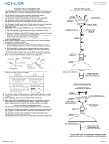
MOUNTING STRAP
ABRAZADERA DE
MONTAJE
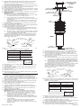
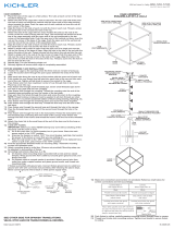
1) Pass wire from fixture through stem and screw stem to top of fixture.
NOTE: Thread locking compound must be applied to all stem
threads as noted with symbol (3) to prevent accidental rotation of
fixture during cleaning, relamping, etc.
2) Pass fixture wire through remaining stems and screw stems together.
3) Thread one small threaded pipe into end of each small loop.
4) Attach small loop to end of last stem.
5) Pass threaded pipe at end of second small loop through hole in canopy.
6) Slip lockwasher over threaded pipe protruding from inside of canopy
and screw hexnut onto threaded pipe.
7) Attach chain link to small loop at end of stem and to loop on canopy.
8) TURN OFF POWER.
IMPORTANT: Before you start, NEVER attempt any work without
shutting off the electricity until the work is done.
a) Go to the main fuse, or circuit breaker, box in your home. Place
the main power switch in the “OFF” position.
b) Unscrew the fuse(s), or switch “OFF” the circuit breaker
switch(s), that control the power to the fixture or room that you
are working on.
c) Place the wall switch in the “OFF” position. If the fixture to be
replaced has a switch or pull chain, place those in the “OFF”
position.
9) Find the appropriate threaded holes on mounting strap. Assemble
mounting screws into threaded holes.
10) Attach mounting strap to outlet box. (Screws not provided). Mounting
strap can be adjusted to suit position of fixture.
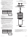
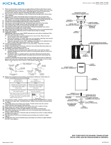
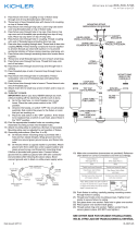
11) Grounding instructions: (See Illus. A or B).
A) On fixtures where mounting strap is provided with a hole and
two raised dimples. Wrap ground wire from outlet box around
green ground screw, and thread into hole.
B) On fixtures where a cupped washer is provided. Attach ground
wire from outlet box under cupped washer and green ground
screw, and thread into mounting strap.
If fixture is provided with ground wire. Connect fixture ground wire
to outlet box ground wire with wire connector. (Not provided.) After
following the above steps. Never connect ground wire to black or
white power supply wires.
12) Make wire connections (connectors not provided.) Reference chart
below for correct connections and wire accordingly.
13) Push fixture to ceiling, carefully passing mounting screws through
holes in canopy.
14) Thread knurl knobs onto mounting screws. Tighten knurl knobs to
secure fixture to ceiling.
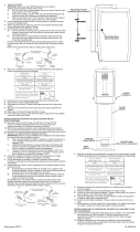
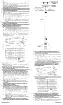
15) Raise glass up to fixture. Slip glass inside cage and pass hole in
glass over socket.
16) Slip spacer over socket.
17) Thread socket ring onto socket. Tighten socket ring to secure glass
in place. (DO NOT over tighten.)
1) Pase el alambre del artefacto a través del vástago y atornille
el vástago al tope del artefacto. NOTA: El compuesto para rosca
estanca se debe aplicar a todas las roscas del vástago como se
notó con el símbolo (3) para impedir la rotación accidental del
artefacto durante la limpieza, instalación de una bombilla nueva, etc.
2) Pase el alambre del artefacto a través de los vástagos restantes y
atornille los vástagos juntos.
3) Rosque un tubo roscado pequeño en el extremo de lazo pequeño.
4) Una la argolla pequeña a la última varilla.
5) Pase el tubo roscado en el extremo del segundo lazo pequeño a
través del agujero en el escudete.
6) Resbale la arandela de seguridad encima del tubo roscado que
sobresale de adentro del capuchón. Atornille la tuerca hexagonal al
tubo roscado.
7) Acople un eslabón de cadena al lazo pequeño en el extremo del
vástago y al lazo en el escudete.
8) APAGUE LA ALIMENTACIÓN ELÉCTRICA.
IMPORTANTE: Antes de comenzar, NUNCA trate de trabajar sin
antes desconectar la corriente hasta que el trabajo se termine.
a) Vaya a la caja principal de fusibles, o interruptor o caja de
circuitos de su casa. Coloque el interruptor de la corriente
principal en posición de apagado “OFF”.
b) Desatornille el (los) fusible (s), o coloque el interruptor o
interruptores del breaker en posición de apagado “OFF”, que
controla (n) la corriente hacia el artefacto o habitación donde
está trabajando.
c) Coloque el interruptor de pared en posición de apagado
“OFF”. Si el artefacto que se va a reemplazar tiene un
interruptor o cadena que se jala, colóquelos en la posición de
apagado “OFF”.
GREEN GROUND
SCREW
CUPPED
WASHER
A
B
OUTLET BOX
GROUND
FIXTURE
GROUND
DIMPLES
WIRE CONNECTOR
(NOT PROVIDED)
OUTLET BOX
GROUND
GREEN GROUND
SCREW
FIXTURE
GROUND
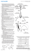
Connect Black or
Red Supply Wire to:
Connect
White Supply Wire to:
Black White
*Parallel cord (round & smooth) *Parallel cord (square & ridged)
Clear, Brown, Gold or Black
without tracer
Clear, Brown, Gold or Black
with tracer
Insulated wire (other than green)
with copper conductor
Insulated wire (other than green)
with silver conductor
*Note: When parallel wires (SPT I & SPT II)
are used. The neutral wire is square shaped
or ridged and the other wire will be round in
shape or smooth (see illus.)
Neutral Wire
Date Issued: 3/15/13
IS-43304-US
CANOPY
ESCUDETE
STEM
VÁSTAGO
KNURL KNOB
PERILLA ESTRADA
3
SMALL LOOP
ARGOLLA PEQUEÑA
3
CHAIN LINK
ESLABÓN DE CADENA
ARANDELA
CONCAVA
A
B
TIERRA DE LA
CAJA DE SALIDA
TORNILLO DE TIERRA,
VERDE
DEPRESIONES
TIERRA
ARTEFACTO
CONECTOR DE ALAMBRE
(NO SE PROVEE)
TIERRA DE LA
CAJA DE SALIDA
TORNILLO DE TIERRA,
VERDE
TIERRA
ARTEFACTO
Conectar el alambre de
suministro negro o rojo al
Conectar el alambre de
suministro blanco al
Negro Blanco
*Cordon paralelo (redondo y liso)
*Cordon paralelo (cuadrado y estriado)
Claro, marrón, amarillio o negro
sin hebra identificadora
Claro, marrón, amarillio o negro
con hebra identificadora
Alambre aislado (diferente del verde)
con conductor de cobre
Alambre aislado (diferente del
verde) con conductor de plata
*Nota: Cuando se utiliza alambre paralelo
(SPT I y SPT II). El alambre neutro es de forma
cuadrada o estriada y el otro alambre será de
forma redonda o lisa. (Vea la ilustracíón).
Hilo Neutral
CAGE
JAULA
GLASS
VIDRIO
SPACER
ESPACIADOR
SOCKET RING
ANILLO DEL CASQUILLO

3
1) Pass wire from fixture through stem and screw stem to top of fixture.
NOTE: Thread locking compound must be applied to all stem threads
as noted with symbol (3) to prevent accidental rotation of fixture
during cleaning, relamping, etc.
2) Pass fixture wire through remaining stems and screw stems together.
3) Thread one small threaded pipe into end of each small loop.
4) Attach small loop to end of last stem.
5) Pass threaded pipe at end of second small loop through hole in canopy.
6) Slip lockwasher over threaded pipe protruding from inside of canopy.
Screw hexnut onto threaded pipe.
7) Attach chain link to small loop at end of stem and to loop on canopy.
8) TURN OFF POWER.
IMPORTANT: Before you start, NEVER attempt any work without
shutting off the electricity until the work is done.
a) Go to the main fuse, or circuit breaker, box in your home. Place
the main power switch in the “OFF” position.
b) Unscrew the fuse(s), or switch “OFF” the circuit breaker
switch(s), that control the power to the fixture or room that you
are working on.
c) Place the wall switch in the “OFF” position. If the fixture to be
replaced has a switch or pull chain, place those in the “OFF”
position.
9) Find the appropriate threaded holes on mounting strap. Assemble
mounting screws into threaded holes.
10) Attach mounting strap to outlet box. (Screws not provided). Mounting
strap can be adjusted to suit position of fixture.
11) Make wire connections (connectors not provided.) Reference chart
below for correct connections and wire accordingly.
12) Push fixture to ceiling, carefully passing mounting screws through
holes in canopy.
13) Thread knurl knobs onto mounting screws. Tighten knurl knobs to
secure fixture to ceiling.
14) Raise glass up to fixture. Slip glass inside cage and pass hole in
glass over socket.
15) Slip spacer over socket.
16) Thread socket ring onto socket. Tighten socket ring to secure glass
in place. (DO NOT over tighten.)
1) Passez le fil dans la tige et vissez la tige en haut du corps du luminaire.
REMARQUE: Appliquer le frein filet sur tous les filets de la tige
indiqués par le symbole (3) pour empêcher la rotation accidentelle
du luminaire pendant le nettoyage, remplacement de lampe, etc.
2) Passez le fil dans les tiges restantes et vissez les tiges ensemble.
3) Visser un petit tube fileté dans l’extrémité de chaque boucle.
4) Attachez la petite bouche à l’extrémité de la tige supérieure.
5) Passer le tube fileté à l’extrémité de la petite bouche par le trou situé
dans le cache.
6) Passer la rondelle de blocage sur le tube fileté sortant de l’intérieur
du cache.Visser l’écrou hexagonal sur le tube fileté.
7) Attacher le maillon de la chaîne à la petite boucle située à l’extrémité
de la tige ainsi qu’à la boucle située sur l’abat-jour.
8) COUPER LE COURANT.
IMPORTANT: TOUJOURS couper l’électricité avant de commencer le
travail.
a) Localiser le coffret à fusibles ou le disjoncteur du domicile.
Mettre l’interrupteur principal en position d’Arrêt.
b) Dévisser le ou les fusibles (ou mettre le disjoncteur sur Arrêt)
qui contrôlent l’alimentation vers le luminaire ou la pièce dans
laquelle le travail est effectué.
c) Mettre l’interrupteur mural en position d’Arrêt. Si le luminaire
à remplacer est doté d’un interrupteur ou d’une chaîne connectée
à l‘interrupteur, placer ces éléments en position d’Arrêt.
9) Trouver les trous filetés appropriés sur la barrette de montage.
Vissez les vis de montage dans les trous filetés.
10) Visser la barrette de montage à la boite de jonction. (Vis non fournies).
La barrette de montage peut etre ajustée pour convenir à la position
de l’applique.
11) Connecter les fils (connecteurs non fournis). Se reporter au tableau
ci-dessous pour faire les connexions.
Connect Black or
Red Supply Wire to:
Connect
White Supply Wire to:
Black White
*Parallel cord (round & smooth) *Parallel cord (square & ridged)
Clear, Brown, Gold or Black
without tracer
Clear, Brown, Gold or Black
with tracer
Insulated wire (other than green)
with copper conductor
Insulated wire (other than green)
with silver conductor
*Note: When parallel wires (SPT I & SPT II)
are used. The neutral wire is square shaped
or ridged and the other wire will be round in
shape or smooth (see illus.)
Neutral Wire
Date Issued: 3/15/13 IS-43304-CB
INSTRUCTIONS
For Assembling and Installing Fixtures in Canada
Pour L’assemblage et L’installation Au Canada
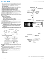
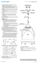
MOUNTING STRAP
PATTE DE FIXATION
CANOPY
CACHE
KNURL KNOB
BOUTON MOLETÉ
SMALL LOOP
PETITE BOUCLE
4
STEM
TIGE
GLASS
VERRE
CHAIN LINK
MAILLON DE LA CHAÎNE
Connecter le fil noir ou
rouge de la boite
Connecter le fil blanc de la boîte
A Noir A Blanc
*Au cordon parallèle (rond et lisse)
*Au cordon parallele (à angles droits el strié)
Au bransparent, doré, marron, ou
noir sans fil distinctif
Au transparent, doré, marron, ou
noir avec un til distinctif
Fil isolé (sauf fil vert) avec
conducteur en cuivre
Fil isolé (sauf fil vert) avec
conducteur en argent
*Remarque: Avec emploi d’un fil paralléle
(SPT I et SPT II). Le fil neutre est á angles
droits ou strié et l’autre fil doit étre rond ou
lisse (Voir le schéma).
Fil Neutre
SOCKET RING
ANNEAU DE LA DOUILLE
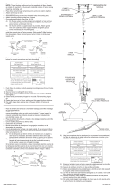
12) Pousser le luminaire vers le plafond en passant soigneusement les
vis de montage par les trous dans le cache.
13) Visser les boutons moletés sur les vis de fixation. Resserrer les boutons
moletés pour fixer le luminaire au plafond.
14) Soulever le verre jusqu’au luminaire. Glisser le verre à l’intérieur de la
cage et passer le trou dans le verre sur la douille.
15) Glisser l’entretoise sur la douille.
16) Resserrer l’anneau de la douille pour bien fixer le verre. (NE PAS
serrer avec excès).
SPACER
ENTRETOISE
CAGE
CAGE
-
 1
1
-
 2
2


Kichler Lighting 43304NI Manual de usuario
- Tipo
- Manual de usuario
- Este manual también es adecuado para
en otros idiomas
- français: Kichler Lighting 43304NI Manuel utilisateur
- English: Kichler Lighting 43304NI User manual
Artículos relacionados
-
 Kichler Lighting 49336AZ Manual de usuario
-
 Kichler Lighting 43754AUB Manual de usuario
-
 Kichler Lighting 42526OZ Manual de usuario
-
 Kichler Lighting 43755AUB Manual de usuario
-
 Kichler Lighting 42562BPT Manual de usuario
-
 Kichler Lighting 2665OZ Manual de usuario
-
 Kichler Lighting 42580OZ Manual de usuario
-
 Kichler Lighting 43670NI Manual de usuario
-
 Kichler Lighting 43767OZ Manual de usuario
-
 Kichler Lighting 43737CLP Manual de usuario


