
INDUSTRIAL
SLIDER 01 C
INDUSTRIAL
SLIDER 01 C

AVVERTENZE PER L’INSTALLATORE
OBBLIGHI GENERALI PER LA SICUREZZA
1) ATTENZIONE! È importante per la sicurezza delle persone seguire attenta-
mente tutta l’istruzione. Una errata installazione o un errato uso del prodotto
può portare a gravi danni alle persone.
2) Leggere attentamente le istruzioni prima di iniziare l’installazione del prodot-
to.
3) I materiali dell’imballaggio (plastica, polistirolo, ecc.) non devono essere
lasciati alla portata dei bambini in quanto potenziali fonti di pericolo.
4) Conservare le istruzioni per riferimenti futuri.
5) Questo prodotto è stato progettato e costruito esclusivamente per l’utilizzo
indicato in questa documentazione. Qualsiasi altro utilizzo non espressamente
indicato potrebbe pregiudicare l’integrità del prodotto e/o rappresentare
fonte di pericolo.
6) GENIUS declina qualsiasi responsabilità derivata dall’uso improprio o diverso
da quello per cui l’automatismo è destinato.
7) Non installare l’apparecchio in atmosfera esplosiva: la presenza di gas o fumi
infiammabili costituisce un grave pericolo per la sicurezza.
8) Gli elementi costruttivi meccanici devono essere in accordo con quanto
stabilito dalle Norme EN 12604 e EN 12605.
Per i Paesi extra-CEE, oltre ai riferimenti normativi nazionali, per ottenere un
livello di sicurezza adeguato, devono essere seguite le Norme sopra riporta-
te.
9) GENIUS non è responsabile dell’inosservanza della Buona Tecnica nella co-
struzione delle chiusure da motorizzare, nonché delle deformazioni che do-
vessero intervenire nell’utilizzo.
10) L’installazione deve essere effettuata nell’osservanza delle Norme EN 12453
e EN 12445. Il livello di sicurezza dell’automazione deve essere C+D.
11) Prima di effettuare qualsiasi intervento sull’impianto, togliere l’alimentazione
elettrica e scollegare le batterie.
12) Prevedere sulla rete di alimentazione dell’automazione un interruttore onni-
polare con distanza d’apertura dei contatti uguale o superiore a 3 mm. È
consigliabile l’uso di un magnetotermico da 6A con interruzione onnipolare.
13) Verificare che a monte dell’impianto vi sia un interruttore differenziale con
soglia da 0,03 A.
14) Verificare che l’impianto di terra sia realizzato a regola d’arte e collegarvi le
parti metalliche della chiusura.
15) L’automazione dispone di una sicurezza intrinseca antischiacciamento costi-
tuita da un controllo di coppia. E' comunque necessario verificarne la sogli di
intervento secondo quanto previsto dalle Norme indicate al punto 10.
16) I dispositivi di sicurezza (norma EN 12978) permettono di proteggere eventuali
aree di pericolo da Rischi meccanici di movimento, come ad Es. schiaccia-
mento, convogliamento, cesoiamento.
17) Per ogni impianto è consigliato l’utilizzo di almeno una segnalazione luminosa
nonché di un cartello di segnalazione fissato adeguatamente sulla struttura
dell’infisso, oltre ai dispositivi citati al punto “16”.
18) GENIUS declina ogni responsabilità ai fini della sicurezza e del buon funziona-
mento dell’automazione, in caso vengano utilizzati componenti dell’impian-
to non di produzione GENIUS.
19) Per la manutenzione utilizzare esclusivamente parti originali GENIUS.
20) Non eseguire alcuna modifica sui componenti facenti parte del sistema
d’automazione.
21) L’installatore deve fornire tutte le informazioni relative al funzionamento
manuale del sistema in caso di emergenza e consegnare all’Utente utilizzato-
re dell’impianto il libretto d’avvertenze allegato al prodotto.
22) Non permettere ai bambini o persone di sostare nelle vicinanze del prodotto
durante il funzionamento.
23) Tenere fuori dalla portata dei bambini radiocomandi o qualsiasi altro datore
di impulso, per evitare che l’automazione possa essere azionata involontaria-
mente.
24) Il transito tra le ante deve avvenire solo a cancello completamente aperto.
25) L’Utente utilizzatore deve astenersi da qualsiasi tentativo di riparazione o
d’intervento diretto e rivolgersi solo a personale qualificato.
26) Tutto quello che non è previsto espressamente in queste istruzioni non è
permesso
IMPORTANT NOTICE FOR THE INSTALLER
GENERAL SAFETY REGULATIONS
1) ATTENTION! To ensure the safety of people, it is important that you read all
the following instructions. Incorrect installation or incorrect use of the
product could cause serious harm to people.
2) Carefully read the instructions before beginning to install the product.
3) Do not leave packing materials (plastic, polystyrene, etc.) within reach of
children as such materials are potential sources of danger.
4) Store these instructions for future reference.
5) This product was designed and built strictly for the use indicated in this
documentation. Any other use, not expressly indicated here, could compro-
mise the good condition/operation of the product and/or be a source of
danger.
6) GENIUS declines all liability caused by improper use or use other than that for
which the automated system was intended.
7) Do not install the equipment in an explosive atmosphere: the presence of
inflammable gas or fumes is a serious danger to safety.
CONSIGNES POUR L'INSTALLATEUR
RÈGLES DE SÉCURITÉ
1) ATTENTION! Il est important, pour la sécurité des personnes, de suivre à la
lettre toutes les instructions. Une installation erronée ou un usage erroné
du produit peut entraîner de graves conséquences pour les personnes.
2) Lire attentivement les instructions avant d'installer le produit.
3) Les matériaux d'emballage (matière plastique, polystyrène, etc.) ne doivent
pas être laissés à la portée des enfants car ils constituent des sources
potentielles de danger.
4) Conserver les instructions pour les références futures.
5) Ce produit a été conçu et construit exclusivement pour l'usage indiqué dans
cette documentation. Toute autre utilisation non expressément indiquée
pourrait compromettre l'intégrité du produit et/ou représenter une source
de danger.
6) GENIUS décline toute responsabilité qui dériverait d'usage impropre ou
différent de celui auquel l'automatisme est destiné.
7) Ne pas installer l'appareil dans une atmosphère explosive: la présence de
gaz ou de fumées inflammables constitue un grave danger pour la sécurité.
8) Les composants mécaniques doivent répondre aux prescriptions des Normes
EN 12604 et EN 12605.
Pour les Pays extra-CEE, l'obtention d'un niveau de sécurité approprié exige
non seulement le respect des normes nationales, mais également le respect
des Normes susmentionnées.
9) GENIUS n'est pas responsable du non-respect de la Bonne Technique dans la
construction des fermetures à motoriser, ni des déformations qui pourraient
intervenir lors de l'utilisation.
10) L'installation doit être effectuée conformément aux Normes EN 12453 et EN
12445. Le niveau de sécurité de l'automatisme doit être C+D.
11) Couper l'alimentation électrique et déconnecter la batterie avant toute
intervention sur l'installation.
12) Prévoir, sur le secteur d'alimentation de l'automatisme, un interrupteur
omnipolaire avec une distance d'ouverture des contacts égale ou supérieure
à 3 mm. On recommande d'utiliser un magnétothermique de 6A avec
interruption omnipolaire.
13) Vérifier qu'il y ait, en amont de l'installation, un interrupteur différentiel avec
un seuil de 0,03 A.
14) Vérifier que la mise à terre est réalisée selon les règles de l'art et y connecter
les pièces métalliques de la fermeture.
15) L'automatisme dispose d'une sécurité intrinsèque anti-écrasement, formée
d'un contrôle du couple. Il est toutefois nécessaire d'en vérifier le seuil
d'intervention suivant les prescriptions des Normes indiquées au point 10.
8) The mechanical parts must conform to the provisions of Standards EN 12604
and EN 12605.
For non-EU countries, to obtain an adequate level of safety, the Standards
mentioned above must be observed, in addition to national legal regulations.
9) GENIUS is not responsible for failure to observe Good Technique in the
construction of the closing elements to be motorised, or for any deformation
that may occur during use.
10) The installation must conform to Standards EN 12453 and EN 12445. The safety
level of the automated system must be C+D.
11) Before attempting any job on the system, cut out electrical power and
disconnect the batteries.
12) The mains power supply of the automated system must be fitted with an all-
pole switch with contact opening distance of 3mm or greater. Use of a 6A
thermal breaker with all-pole circuit break is recommended.
13) Make sure that a differential switch with threshold of 0.03 A is fitted upstream
of the system.
14) Make sure that the earthing system is perfectly constructed, and connect
metal parts of the means of the closure to it.
15) The automated system is supplied with an intrinsic anti-crushing safety device
consisting of a torque control. Nevertheless, its tripping threshold must be
checked as specified in the Standards indicated at point 10.
16) The safety devices (EN 12978 standard) protect any danger areas against
mechanical movement Risks, such as crushing, dragging, and shearing.
17) Use of at least one indicator-light is recommended for every system, as well
as a warning sign adequately secured to the frame structure, in addition to
the devices mentioned at point “16”.
18) GENIUS declines all liability as concerns safety and efficient operation of the
automated system, if system components not produced by GENIUS are used.
19) For maintenance, strictly use original parts by GENIUS.
20) Do not in any way modify the components of the automated system.
21) The installer shall supply all information concerning manual operation of the
system in case of an emergency, and shall hand over to the user the warnings
handbook supplied with the product.
22) Do not allow children or adults to stay near the product while it is operating.
23) Keep remote controls or other pulse generators away from children, to
prevent the automated system from being activated involuntarily.
24) Transit through the leaves is allowed only when the gate is fully open.
25) The user must not attempt any kind of repair or direct action whatever and
contact qualified personnel only.
26) Anything not expressly specified in these instructions is not permitted.

ITALIANO
1
INDICE
DICHIARAZIONE CE DI CONFORMITÁ pag.1
CARATTERISTICHE TECNICHE pag.2
COLLEGAMENTI ELETTRICI CON 400V 3ph pag.2
DESCRIZIONE pag.3
PROGRAMMAZIONE pag.4
CONDIZIONI DI ANOMALIA pag.5
VERIFICA DEL SENSO DI ROTAZIONE pag.5
VERIFICA DEL COLLEGAMENTO DEI FINECORSA pag.5
COLLEGAMENTI ELETTRICI CON 230V 3ph pag.5
NOTE pag.5
DICHIARAZIONE CE DI CONFORMITÁ
Fabbricante: GENIUS S.r.l.
Indirizzo: Via Padre Elzi, 32
24050 - Grassobbio
BERGAMO - ITALY
Dichiara che: L'apparecchiatura elettronica INDUSTRIAL SLIDER 01 C
• è conforme ai requisiti essenziali di sicurezza delle seguenti direttive :
73/23/CEE e successiva modifica 93/68/CEE.
89/336/CEE e successiva modifica 92/31/CEE e 93/68/CEE
Nota aggiuntiva:
Questo prodotto è stato sottoposto a test in una configurazione tipica omogenea (tutti prodotti di costruzione GENIUS S.r.l.).
Grassobbio, 03 Maggio 2004
L’amministratore delegato
D. Gianantoni

ITALIANO
2
INDUSTRIAL SLIDER 01 C
2. COLLEGAMENTI ELETTRICI CON 400V 3ph (N.B.: per i collegamenti con 230V 3ph vedi Cap.8)
!!
!!
!Prima di effettuare qualsiasi tipo di intervento sulla scheda (collegamenti, programmazione, manutenzione) togliere sempre
l’alimentazione elettrica.
Attenzione: Scollegando i connettori J3 e J4 può essere presente alta tensione sulle uscite lampeggiatore e motore.
Seguire i punti 10, 11, 12, 13,14 degli OBBLIGHI GENERALI PER LA SICUREZZA. Separare sempre i cavi di alimentazione da quelli di
comando e di sicurezza (pulsante, ricevente, fotocellule ecc.). Per evitare qualsiasi disturbo elettrico utilizzare guaine separate.
1.1. LAY-OUT SCHEDA
1. CARATTERISTICHE TECNICHE
Tab. 1 CARATTERISTICHE TECNICHE
Tab. 2 COMPONENTI SCHEDA
enoizatnemilA
zH05)%01-6+(N+hp3V004
zH05)%01-6+(hp3V032
irotomxamociraC WK3,1
enoizatnemilA
irossecca
cdV42
i
rosseccaxamociraC Am005
enoizatnemilA
aipsadapmal
)xamW5(~V42
etneibmaarutarepmeT C°55+C°02-
enoizetorpidili
bisuF irossecca/erotamrofsartoiramirp
idiparirottennoC snip5itneveciredehcsrep
issergnI
/potS/elaizrapnepO
/nepO
asroc-eniF/arusuihCezzerucis
eticsU
/erotaiggepmal/aipsadapmal
irosseccaenoizatnemila/erotom
cdV42
en
oizammargorP
081-021-06-03-51-01-5(asuapopmet
/C-B-2E-1E-2S-1S-2A-1Aehcigol/).ces
oiggepmalerp
erotomarut
anerF assif
idenoizazziropmeT
azzerucis
.ces552
1F )erotamrofsart(odiparV052/A5F02x51FelibisuF 3J )W06xam~V032(erotaiggepmalaticsuareittesroM
2F )irossecc
a(otadratirV052/A6,1T02x52FelibisuF 4J erotomaticsuareittesroM
1WS TESERidetnasluP 5J aenilidenoizatnemilao
ssergniareittesroM
1SD enoizammargorpidirotturretniorciM 1KL aipsadapmalotalocnivsottatnocrepollecitnoP
de
L issergniilgedotatsenoizalangesidsdeL 7-6LR erotoméleR
1J PRitnevecir/acifidocededehcsodiparerottennoC 8LR
arutanerféleR
2J irossecca/issergnienoisnetassabareittesroM
Fig. 1
Fig. 2

ITALIANO
3
5 = Comune comandi
6 = Comune alimentazione accessori
7 = Positivo alimentazione accessori 24 Vdc (+)
Il carico max. degli accessori è 500mA.
Per il calcolo degli assorbimenti, fare riferimento alle istruzioni dei
singoli accessori.
9 = Uscita lampada spia (Warning Light) 24 Vac
Il carico massimo della lampada spia è di 5W.
Per il funzionamento della lampada spia fare riferimento alla
programmazione dei microinterruttori.
!!
!!
!Se si taglia il ponticello LK1, si ottiene un contatto pulito tra i
morsetti 8 e 9 (vedi fig.4).
10 = Positivo alimentazione finecorsa induttivi 24Vdc (+)
11 = Comune finecorsa
12 = Finecorsa apertura (N.O.)
13 = Finecorsa chiusura (N.O.)
3.3. MORSETTIERA J3 (alta tensione)
Morsettiera per il collegamento del lampeggiatore (max 60W).
3.4. MORSETTIERA J4 (alta tensione)
Morsettiera per il collegamento del motore.
3.5. MORSETTIERA J5 (alta tensione)
Morsettiera per l'alimentazione 400V 3ph + Neutro - 50 Hz (vedi
fig.2) oppure 230V 3ph - 50 Hz (vedi fig.5).
3.6. LED DI SEGNALAZIONE
Sulla scheda sono presenti 6 Led che riportano lo stato degli
ingressi di morsettiera:
Led acceso = contatto chiuso
Led spento = contatto aperto
Tab. 3 STATO DEI LED
Nota bene: in neretto la condizione dei leds con automazione
chiusa e centrale alimentata.
3. DESCRIZIONE
3.1. CONNETTORE J1
Inserire nel connettore a pettine J1(Fig. 1) la scheda ricevente
come indicato in Fig. 3.
Per la programmazione della scheda ricevente riferirsi alle singo-
le istruzioni.
Inserimento e disinserimento vanno effettuati dopo aver tolto
tensione.
3.2. MORSETTIERA J2 (bassa tensione)
1 = OPEN A (N.O.) - Apertura totale
Si intende qualsiasi datore d'impulso con contatto N.O. che,
azionato, dà luogo a un movimento di apertura del cancello.
Nelle logiche A, E ed S comanda sia l'apertura che la chiusura.
Per installare più dispositivi di Open A, collegare i contatti N.O. in
parallelo.
2 = OPEN B (N.O.) - Apertura pedonale / Chiusura
Si intende qualsiasi datore d'impulso con contatto N.O. che,
nelle logiche A, E ed S, dà luogo a un movimento di apertura
pedonale del cancello. Nelle logiche B e C comanda un movi-
mento di chiusura.
Per installare più dispositivi di Open B, collegare i contatti N.O. in
parallelo.
3 = Comando di STOP (N.C.)
Si intende qualsiasi dispositivo (es. pulsante) che, aprendo un
contatto, arresta il movimento del cancello.
Per installare più dispositivi d’arresto, collegare i contatti N.C. in
serie.
!!
!!
! Se non vengono collegati dispositivi di Stop, ponticellare
l’ingresso col comune (morsetto 5).
4 = FSW Contatto sicurezze in chiusura (N.C.)
Per sicurezze, si intendono tutti i dispositivi (fotocellule, coste sen-
sibili, spire magnetiche) con contatto N.C. che in presenza di un
ostacolo nell’area da loro protetta, intervengono interrompen-
do il movimento del cancello. ll compito delle sicurezze in chiu-
sura è quello di salvaguardare la zona interessata dal movi-
mento del cancello, durante la fase di chiusura.
L’intervento delle sicurezze durante la fase di chiusura, provoca
l’inversione del movimento del cancello, mentre durante la fase
di apertura non ha nessun effetto. Le sicurezze di chiusura, se
impegnate a cancello aperto o in pausa, ne impediscono la
chiusura.
Per installare più dispositivi di sicurezza, collegare i contatti N.C.
in serie.
!!
!!
!Se non vengono collegati dispositivi di sicurezza in chiusura,
ponticellare questo ingresso col comune (morsetto 5).
LK1 INTEGRO
LK1 INTERROTO
(contatto svincolato)
DEL OSECCA OTNEPS
ANEPO ovittaodnamoc ovittaniodnamoc
BNEPO ovittaodnamoc ovittaniodnamoc
POTSovittaniodnamoc ovittaodnam
oc
WSFetangepmisidezzerucis etangepmiezzerucis
CCF orebilarusuihcasrocenif
arusuihcasrocenif
otapucco
ACForebi
larutrepaasrocenif
arutrepaasrocenif
otapucco
Fig. 3
Fig. 4

ITALIANO
4
4. PROGRAMMAZIONE
Per programmare il funzionamento dell'automazione è neces-
sario agire sugli appositi microinterruttori come da schema se-
guente.
(1)
I tempi di pausa comprendono l'eventuale prelampeggio.
(2)
Il prelampeggio inizia 5" prima di ogni movimento.
!!
!!
! Dopo ogni intervento sulla programmazione è necessario
premere il pulsante di RESET.
Logiche di funzionamento
Quelle disponibili sono:
A1/A2 = "Automatica" S1/S2 = "Sicurezza"
E1/E2/B = "Semiautomatica" C = "Uomo presente"
Il comportamento dell'automazione nelle diverse logiche, è in-
dicato nelle Tab. 4-5-6-7-8-9-10-11.
Tempo di pausa
Il tempo di pausa è il tempo di sosta In apertura prima della
richiusura quando è stata selezionata una logica automatica.
I tempi di pausa comprendono l'eventuale prelampeggio.
Funzionamento lampada spia
Permette di differenziare il comportamento della lampada spia
in chiusura tramite intermittenza.
Prelampeggio
E' possibile selezionare un prelampeggio di 5 sec. del lampeg-
giatore prima di ogni movimento. Ciò permette di avvisare chiun-
que sia in prossimità del cancello, dell' immi-nente movimento.
Tab.4 LOGICA A1 (AUTOMATICA)
Tab.5 LOGICA A2 (AUTOMATICA PLUS)
Tab.6 LOGICA S1 (SICUREZZA)
Tab.7 LOGICA S2 (SICUREZZA PLUS)
Tab.8 LOGICA E1 (SEMIAUTOMATICA)
Tab.9 LOGICA E2 (SEMIAUTOMATICA PLUS)
Tab.10 LOGICA B (SEMIAUTOMATICA)
acigoL 1WS 2WS 3WS
1ENONONO
BFFONONO
2SNOFFONO
2EFFOFFONO
1ANONOFFO
CFFONOFFO
1SNOFFOFFO
2AFFOFFOFFO
)ces(asuapopmeT
)1(
acigoL
2A-2A-1A1S4WS5WS
551NONO
0103FFONO
0306NOFFO
021081FFOFFO
aipsadapmalotnemanoiznuF
ollecnacotatS
6WSosuihCotrepa/arutrepanIarusuihcnI
NO
atnepSassifecuL
assifecuL
FFOetna
iggepmaL
oiggepmalerP
)2(
7WS
iSNO
oNFFO
1AACIGOL ISLUPMI
OLLECNACOTATSBNEPO-ANEPO
1()
POTSEZZERUCIS
osuihC
eduihcireerpa
idopmetliopod
asuap
)2(
otteffenussenotteffenussen
asuapniotrepA "5opodeduihcir
)3(
oiggetnocliaccolb
asuapalalegnoc
ongepmisidlaonif
arusuihcnI otomlietrevniaccolbisotomlietrevni
arutrepanI ot
teffenussenaccolbisotteffenussen
otaccolB eduihcir
)2(
otteffenussenotteffenussen
2AACIGOL ISLUPMI
OLLECNACOTATSBNEPO-ANEPO
1()
POTSEZZERUCIS
osuihC
eduihcireerpa
idopmetliopod
asuap
)2(
otteffenussenotteffenussen
asuapniotrepA "5opodeduihcir
)3(
oiggetnocliaccolb
ongepmisidla
"5opodeduihcir
arusuihcnI otomlietrevniaccolbis
laetrevnieaccolb
ongepmisid
)2(
arutrepanI otteffenussenaccolbisotteffenussen
otaccolB eduihcir
)2(
otteffenussenotteffenussen
1SACIGOL ISLUPMI
OLLECNACOTATSBNEPO-ANEPO
1()
POTSEZZERUCIS
osuihC
opodeduihcireerpa
asuapidopmetli
)2(
otteffenussenotteffenussen
asuapniotrepA otibuseduihcir
)3-2(
oiggetnocliaccolb
ongepmisidla
"5opodeduihcir
arusuihcnI otomlietrevniaccolbisotomlietrevni
arutrepanI otomli
etrevniaccolbisotteffenussen
otaccolB eduihcir
)2(
otteffenussenotteffenussen
2SACIGOL ISLUPMI
OLLECNACOTATSBNEPO-ANEPO
1()
POTSEZZERUCIS
osuihC
opodeduihcireerpa
asuapidopmetli
)2(
otteffenussenotteffenussen
asuapniotrepA otibuseduihcir
)3-2(
oiggetnocliaccolb
onifasuapalalegnoc
ongepmisidla
arusuihcnI otomlietrevniaccolbis
laetrevnieaccolb
ongepmis
id
)2(
arutrepanI otomlietrevniaccolbisotteffenussen
otaccolB eduihcir
)2(
otteffenussenotteffenussen
1EACIGOL ISLUPMI
OLLECNACOTATSBNEPO-ANEPO
1()
POTSEZZERUCIS
osuihC erpa
)2(
otteffenussenotteffenussen
asuapniotrepA eduihcir
)2(
otteffenussenotteffenussen
arusuihcnI otomlietrevniaccolbisotomlietrevni
arutrepanI accolbisaccolbisotteffenus
sen
otaccolB
ezzerucisa(eduihciR
)erpairetangepmi
)2(
otteffenussenotteffenussen
2EACIGOL ISLUPMI
OLLECNACOTATSBNEPO-ANEPO
1()
POTSEZZERUCIS
osuihC erpa
)2(
otteffenussenotteffenussen
asuapniotrepA eduihcir
)2(
otteffenussenotteffenussen
arusuihcnI otomlietrevniaccolbis
laetrevnieaccolb
ongepmisid
)2(
arutrepanI accolbisaccolbisotteffenussen
otaccolB
ezzerucisa(eduihcir
)erpairetangepmi
)2(
otteffenussenotteffenussen
BACIGOL ISLUPMI
OLLECNACOTATSANEPOBNEPO
4()
EZZERUCISPOTS
osuihC erpa
)2(
otteffenussenotteffenussenotteffenussen
asuapniotrepA otteffenusseneduihc
)2(
alecsibini
arusuihc
otteffenussen
arusuihcnI otteffenussenotteffenussen
liaccolb
otnemivom
liaccolb
otnemivom
a
rutrepanI otteffenussenotteffenussenotteffenussen
liaccolb
otnemivom
otaccolB
atelpmoc
arutrepa'l
)2(
alatelpmoc
arusuihc
)2(
alecsibini
arusuihc
otteffenussen

ITALIANO
5
Tab.11 LOGICA C (UOMO PRESENTE)
(1)
L'ingresso OPEN B comanda l'apertura parziale.
(2)
Con prelampeggio selezionato, il movimento inizia dopo 5
sec.
(3)
Se l'impulso è inviato durante il prelampeggio, riconta.
(4)
L'ingresso OPEN B comanda la chiusura.
(5)
Per ottenere il movimento del cancello è necessario tenere
premuto il pulsante. Al rilascio il cancello si arresta.
5. CONDIZIONI DI ANOMALIA
Le seguenti condizioni provocano effetti nel normale funziona-
mento dell'automazione:
a- errore del microprocessore
b- intervento della temporizzazione elettronica di sicurezza (in-
terruzione del funzionamento dopo un tempo di lavoro con-
tinuo superiore a 255 sec.)
c- fine-corsa scollegati (o entrambi impegnati)
•Le condizioni a e b hanno solo l'effetto di comandare uno
stop all'automazione.
•La condizione c provoca una situazione di allarme inibendo
qualsiasi attività:
Il ripristino del normale funzionamento avviene solo dopo aver
eliminato la causa dell'allarme e premuto il pulsante di RESET (o
interrotto momentaneamente la tensione d'alimentazione).
Per ottenere la segnalazione di tale condizione, è necessario
collegare la lampada spia: l'allarme è segnalato mediante
un'intermittenza molto veloce (0.25 sec).
6. VERIFICA DEL SENSO DI ROTAZIONE
1) Sbloccare l'operatore, portarlo manualmente a metà corsa
e ribloccarlo.
2) Alimentare il sistema, quindi premere il pulsante di RESET.
3) Dare un comando di Open all'operatore, verificare che il
cancello si muova nella direzione di apertura e quindi pre-
mere il pulsante di RESET per arrestare il movimento dell'anta.
4) Nel caso in cui il senso di rotazione sia errato, invertire il ca-
blaggio dei cavi T1 e T3 del motore elettrico.
7. VERIFICA DEL COLLEGAMENTO DEI FINECORSA
Comandare l'apertura del cancello e verificare che, ad anta
aperta, il led FCC sia acceso ed il led FCA sia spento.
Comandare la richiusura del cancello (o attendere il tempo
pausa in caso di logica automatica) e verificare che, ad anta
chiusa, il led FCA sia acceso ed il led FCC sia spento.
Nel caso in cui i led siano invertiti, scambiare tra loro i cavi colle-
gati sui morsetti 12 e 13.
CACIGOL ITUMERPERPMESIDNAMOC ISLUPMI
OLLECNACOTATSANEPO
)4(
BNEPO
)5-4(
EZZERUCISPOTS
osuihC erpaotteffenussenotteffenussenotteffenussen
asuapniotrepA otteffenusseneduihc
alecsibini
ar
usuihc
otteffenussen
arusuihcnI otteffenussen
liaccolb
otnemivom
liaccolb
otnemivom
arutrepanI otteffenussenott
effenussen
liaccolb
otnemivom
otaccolB
atelpmoc
arutrepa'l
alatelpmoc
arusuihc
alecsibini
arusuihc
otteffenusse
n
8. COLLEGAMENTI ELETTRICI CON 230V 3ph
Per collegare l'apparecchiatura ad una linea 230 V trifase, se-
guire lo schema di fig.5.
N.B.: Il motore elettrico del motoriduttore dovrà essere del tipo
230V 3ph.
9. NOTE
Fig. 5

ENGLISH
6
CE DECLARATION OF CONFORMITY
Manufacturer : GENIUS S.r.l.
Address: Via Padre Elzi, 32
24050 - Grassobbio
BERGAMO - ITALY
Declares that: Electronic control unit INDUSTRIAL SLIDER 01 C
• conforms to the essential safety requirements of the following directives:
73/23/EEC and subsequent amendment 93/68/EEC.
89/336/EEC and subsequent amendment 92/31/EEC and 93/68/EEC
Additional information:
This product underwent a test in a typical, uniform configuration (all products manufactured by GENIUS S.r.l.).
Grassobbio, 03 May 2004
The Managing Director
D. Gianantoni
CONTENTS
CE DECLARATION OF CONFORMITY pag.6
ELECTRICAL CONNECTIONS WITH 400V 3ph pag.7
TECHNICAL SPECIFICATIONS pag.7
DESCRIPTION pag.8
PROGRAMMING pag.9
FAULT CONDITIONS pag.10
LIMIT SENSORS CONNECTION CHECK pag.10
ELECTRICAL CONNECTIONS WITH 230V 3ph pag.10
NOTES pag.10

ENGLISH
7
INDUSTRIAL SLIDER 01 C
1. TECHNICAL SPECIFICATIONS
TABLE 1: TECHNICAL SPECIFICATIONS
1.1. LAY-OUT
TABLE 2: COMPONENTS
2. ELECTRICAL CONNECTIONS WITH 400V 3ph (N.B.: for connection to 230 V 3ph, see Chapter 8)
!!
!!
! Before attempting any work on the card (connections, programming, maintenance), always turn off power.
Warning: If plugs J3 and J4 are disconnected, high voltage may be present on the flashlight and motor outputs.
Observe points 10, 11, 12, 13 and14 of the GENERAL SAFETY RULES. Always separate power cables from control and safety cables
(push-button receiver, photocells, etc.). To prevent any electrical noise whatever, use separate sheaths.
ylppusrewoP
zH05)%01-6+(N+hp3V004
zH05)%01-6+(hp3V032
daolxamrotoM WK3,1
rewopseirosseccA
ylppus
cdV42
daolxa
mseirosseccA Am005
rewopthgilgininraW
ylppus
)xamW5(~V42
egnarerutarepmeT C°55+C°02-
sesuF
gnidniwyramirpremr
ofsnart
seirossecca
sgulptif-kciuQ sreviecerrof
stupnI
erusolC/potS/nepolaitraP/nepO
srosnes-timiL/secivedy
tefas
stuptuO
/rotom/thgilhsalf/thgilgninraw
seirosseccacdV42otylppusrewop
gnimmargorP
).ces081-021-06-03-
51-01-5(emitesuap
-erp/C-B-2E-1E-2S-1S-2A-1Ascigol/
gnihsalf
gnikarbrotoM dexif
gnimitytefaS .ces552
1F )remrofsnart(diparV052/A5F02x51FesuF 3J )W06xam~V032(draoblanimrettuptuothgilhsalF
2F )seirossecca(deya
ledV052/A6,1T02x52FesuF 4J draoblanimrettuptuorotoM
1WS nottub-hsupTESER 5J draoblanimrettupniylppusrewopen
iL
1SD sehctiwsorcimgnimmargorP 1KL tcatnoceerfthgilgninrawrofegdirB
deL sDELgnillangissutatstupnI 7-6LR yale
rrotoM
1J sreviecerrofgulptif-kciuQ 8LR yalergnikarB
2J seirossecca/stupnirofdraoblanimretegatlovwoL
Fig. 1
Fig. 2

ENGLISH
8
3. DESCRIPTION
3.1. J1 PLUG
Insert the receiver card in the block connector J1 (Fig. 2) as
indicated in Fig. 3.
For programming the receiver card, consult the individual
instructions.
3.2. TERMINAL BOARD J2 (low voltage)
1 = OPEN A (N.O.) – Total opening
This is any pulse generator with N.O. contact which, when
activated, produces a gate opening movement. In A, E and S
logics, it commands both opening and closing.
To install several Open A devices, connect N.O. contacts in
parallel.
2 = OPEN B (N.O.) – Opening for pedestrians / Closing
This is any pulse generator with N.O. contact which, when
activated in logics A, E and S, produces a gate opening
movement for pedestrians. In B and C logics, it commands a
closing movement.
To install several Open B devices, connect N.O. contacts in
parallel.
3 = STOP command (N.C.)
This is any device (e.g. a push-button) which, by opening a
contact, stops gate movement.
To install several stop devices, connect the N.C. contacts in
series.
!!
!!
! If Stop devices are not connected, link the input to the
common contact (terminal 5) via a jumper.
4 = FSW closing safety devices contact (N.C.)
Safety devices are all devices (photocells, sensitive edges,
magnetic coils) with N.C. contact, which, if there is an obstacle
in the area they protect, operate to interrupt gate movement.
The purpose of the closing safety devices is to protect the gate
movement area during closing.
If the safety devices are tripped during closure, gate movement
is reversed, whereas they have no effect during opening. If used
when the gate is open or pausing, closing safety devices prevent
its closing.
To install several safety devices, connect the N.C. contacts in
series.
!!
!!
! If closing safety devices are not connected, link this input to
the common contact (terminal 5) via a jumper.
5 = Common contact for commands
6 = Negative of accessories power supply
7 = 24 Vdc (+) power supply for accessories
Max load of accessories is 500 mA. To calculate absorption values,
refer to the instructions for individual accessories.
9 = Warning light output (24 Vac)
The maximum load of the warning light is 5 W. For instructions on
operation of the warning light, consult microswitch programming.
!!
!!
! If you cut out jumper LK1, you obtain a voltage free contact
between terminals 8 and 9 (see fig. 6).
10 = 24 Vdc (+) power supply for inductive limit switch
11 = Limit switch common contact
12 = Opening limit switch (N.O.)
13 = Closing limit switch (N.O.)
3.3. TERMINAL BOARD J3 (high voltage)
Terminal board for connecting flashlight (max 60W).
3.4. TERMINAL BOARD J4 (high voltage)
Terminal board for connection of motor.
3.5. TERMINAL BOARD J5 (high voltage)
Terminal board for supplying power of 400V 3ph + Neutral - 50 Hz
(see fig.2) or 230V 3ph - 50 Hz (see fig.5).
3.6. SIGNALLING LEDS
6 LEDs are fitted on the card, indicating status of terminal board
inputs:
Led lighted = contact closed
Led off = contact open
TABLE 3: STATUS OF LEDS
NB.: The status of the LEDs while the gate is at rest are shown in
bold.
INTERRUPTED LK1
(Free contact)
COMPLETE LK1
DEL DETHGIL FFO
ANEPO evitcadnammoc evitcanidnammoc
BNEPO evitcadnammoc evitcanidnammoc
POTSevitcanidnammoc evitcadnammoc
W
SF
tonsecivedytefas
gnitarepo
gnitareposecivedytefas
CCF eerfrosnestimilgnisolc
rosnestimilgnisolc
degagne
AC
Feerfrosnestimilgninepo
rosnestimilgninepo
degagne
Fig. 3
Fig. 4

ENGLISH
9
4. PROGRAMMING
To program operation of automation, use the microswitches as
shown below.
(1)
Pause times include pre-flashing if any
(2)
Pre-flashing begins 5” before every movement.
!!
!!
! You must press the RESET push-button after every
programming job.
Function logics
The following are available:
A1/A2 = “Automatic” S1/S2 = “Safety”
E1/E2/B = “Semi-automatic” C = “Dead man”
Operation of automation in the different logics is indicated in
Tables 4-5-6-7-8-9-10-11.
Pause time
Pause time is waiting time in open position before re-closing when
an automatic logic was selected.
Pause times include pre-flashing if any
Operation of warning light
Used to change the appearance of the warning light at closing
by making it flash.
Pre-flashing
Flashlight pre-flashing time of 5 sec before any movement can
be selected. This warns anyone near the gate that it is about to
move.
TABLE 4 LOGIC A1 (AUTOMATIC)
TABLE 5 LOGIC A2 (AUTOMATIC PLUS)
TABLE 6 LOGIC S1 (SAFETY)
TABLE 7 LOGIC S2 (SAFETY PLUS)
TABLE 8 LOGIC E1 (SEMI-AUTOMATIC)
TABLE 9 LOGIC E2 (SEMI-AUTOMATIC PLUS)
TABLE 10 LOGIC B (SEMI-AUTOMATIC)
cigoL 1WS 2WS 3WS
1ENONONO
BFFONONO
2SNOFFONO
2EFFOFFONO
1ANONOFFO
CFFONOFFO
1SNOFFOFFO
2AFFOFFOFFO
)ces(emitesuaP
)1(
cigoL
2A-2A-1A1S4WS5WS
551NONO
0103FFONO
0306NOFFO
021081FFOFFO
thgilgninrawfonoitarepO
sutatsetaG
6WSdesolCnepO/gninepOgnisolC
NO
thgiL
ffO
thgilydaetS
thgiL
FFOgnihsalF
gnihsalf-erP
)2(
7WS
seYNO
oNFFO
1ACIGOL SESLUP
SUTATSETAGBNEPO-ANEPO
1()
POTSSECIVEDYTEFAS
desolC
sesolcdnasnepo
emitesuapretfa
)2(
tceffeontceffeon
esuapnonepO "5retfasesolc-er
)3(
tnuocehtspots
litnuesuapsezeerf
tnemegagnesid
gnisolC noitomsesreverspotsnoitomsesrever
gninepO tceffeonspotstc
effeon
deppotS sesolc-er
)2(
tceffeontceffeon
2ACIGOL SESLUP
SUTATSETAGBNEPO-ANEPO
1()
POTSSECIVEDYTEFAS
desolC
sesolcdnasnepo
emitesuapretfa
)2(
tceffeontceffeon
esuapnonepO "5retfasesolc-er
)3(
tnuocehtspots
,degagnesidnehw
”5retfasesolc-er
gnisolC noitomsesreverspots
tasesreverdnaspot
tnemegagnesid
)2(
gninepO tceffeonspotstceffeon
deppotS sesolc-er
)2(
tceffeontceffeon
1SCIGOL SESLUP
SUTATSETAGBNEPO-ANEPO
1()
POTSSECIVEDYTEFAS
desolC
sesolcdnasnepo
emitesuapretfa
)2(
tceffeontceffeon
esuapnonepO yletaidemmisesolc
)3-2(
tnuocehtspots
,degagnesidnehw
”5retfasesolc-er
gnisolC noitomsesreverspotsnoitomsesrever
gninepO onoitomsesre
verspotstceffeon
deppotS sesolc-er
)2(
tceffeontceffeon
2SCIGOL SESLUP
SUTATSETAGBNEPO-ANEPO
1()
POTSSECIVEDYTEFAS
desolC
sesolcdnasnepo
emitesuapretfa
)2(
tceffeontceffeon
esuapnonepO yletaidemmisesolcr
)3-2(
tnuocehtspots
litnuesuapsezeerf
tnemegagnesid
gnisolC noitomsesreverspots
tasesreverdnaspots
tnemegagnesid
)2(
gninepO noitomsesreverspotstceffeon
deppotS sesolc-er
)2(
tceffeontceffeon
1ECIGOL SESLUP
OLLECNACOTATSBNEPO-ANEPO
1()
POTSSECIVEDYTEFAS
desolC snepo
)2(
tceffeontceffeon
esuapnonepO sesolc-er
)2(
tceffeontceffeon
gnisolC noitomsesreverspotsnoitomsesrever
gninepO spotsspotstceffeon
deppotS
ytefasnehw(sesolc-
er
ti,degagnesecived
)snepo-er
)2(
tceffeontceffeon
2ECIGOL SESLUP
SUTATSETAGBNEPO-ANEPO
1()
POTSEZZERUCIS
desolC snepo
)2(
tceffeontceffeon
esuapnonepO sesolc-er
)2(
tceffeontceffeon
gnisolC noitomsesreverspots
tasesreverdnaspots
tnemegagnesid
)2(
gninepO spotsspotstceffeon
deppotS
ytefasnehw(sesolc-er
-erti,degagnesecived
)snepo
)2(
tceffeontceffeon
BCIGOL SESLUP
SUTATSETAGANEPOBNEPO
4()
SECIVEDYTEFASPOTS
desolC snepo
)2(
tceffeontceffeontceffeon
esuapnonepO tceffeonsesolc
)2(
gnisolcstneverptceffeon
gnisolC tceffeontceffeontnemevomspotstnemevomspots
gninepO tceffeontceffeontceffeontneme
vomspots
deppotS
setelpmoc
gninepo
)2(
setelpmoc
gnisolc
)2(
gnisolcstneverptceffeon

ENGLISH
10
TABLE 11 LOGIC C (DEAD MAN)
(1)
OPEN B input commands partial opening.
(2)
With pre-flashing selected, movement begins after 5 sec.
(3)
If the pulse is sent during pre-flashing, counting is restarted.
(4)
OPEN B input commands closing.
(5)
Push-button must be kept pressed to activate gate movement.
When the push-button is released, the gate stops.
5. FAULT CONDITIONS
The following conditions cause certain effects to normal
operation of automation:
a- microprocessor error
b- safety electronic timing tripped (operation is interrupted if
continuous work time exceeds 255 sec. ).
c- limit sensors disconnected (or both engaged)
• Conditions a and b cause automation to stop and nothing
more.
• Condition c causes an alarm situation disabling any activity:
Normal operation can be restored only after eliminating the
alarm cause and pressing the RESET push-button (or turning off
power supply momentarily).
To have this condition signalled, the warning light must be
connected: the alarm is signalled by very rapidly flashing light
(0.25 sec).
6. ROTATION DIRECTION CHECK
1) Release the operator, take it manually to mid-travel and re-
lock it.
2) Power up the system and then press the RESET push-button.
3) Give an Open command to the operator, check if the gate
moves in opening direction and then press the RESET push-
button to stop the leaf moving.
4) If rotation direction is incorrect, change over wiring of cables
T1 and T3 of the electric motor.
7. LIMIT SENSORS CONNECTION CHECK
Command opening of the gate, and check if, with the leaf
open, the FCC LED is lighted and the FCA LED is off.
Command the gate to re-close (or wait for pause time to elapse
in case of automatic logic) and check if, with the leaf closed,
the FCA LED is lighted and the FCC LED is off.
If the LEDs are reversed, change over the cables connected to
terminals 12 and 13.
CCIGOL YLSUOUNITNOCNWODDLEHSLORTNOC
SESLUP
SUTATSETAGANEPO
)4(
BNEPO
)5-4(
SECIVEDYTEFASPOTS
desolC snepotceffeontceffeontceffeon
esuapnonepO tceffeonsesolcgnisolcstneverptceffeon
gnisolC t
ceffeontnemevomspotstnemevomspots
gninepO tceffeontceffeontnemevomspots
deppotS
setelpmoc
gninepo
setelpmoc
gnis
olc
gnisolcstneverptceffeon
8. ELECTRICAL CONNECTIONS WITH 230V 3ph
To connect the appliance to a 3-phase 230 V mains, observe
the diagram in F ig.8.
N.B.: The electric motor of the gearmotor must be 230V 3-phase.
9. NOTES
Fig. 5

FRANÇAIS
11
DECLARATION CE DE CONFORMITE
Fabricant: GENIUS S.r.l.
Adresse: Via Padre Elzi, 32
24050 - Grassobbio
BERGAMO - ITALIE
Déclare que: L'armoire électronique INDUSTRIAL SLIDER 01 C
• est conforme aux conditions essentielles de sécurité requises par les directives suivantes :
73/23/CEE et modification 93/68/CEE successive,
89/336/CEE et modifications 92/31/CEE et 93/68/CEE successives.
Note supplémentaire:
Ce produit a été soumis à des essais dans une configuration typique homogène (tous les produits sont fabriqués par GENIUS S.r.l.).
Grassobbio, le 03 Mai 2004
L’Administrateur Délégué
D. Gianantoni
INDEX
DECLARATION CE DE CONFORMITE pag.11
CARACTERISTIQUES TECHNIQUES pag.12
CONNEXIONS ELECTRIQUES AVEC 400V 3ph pag.12
DESCRIPTION pag.13
PROGRAMMATION pag.14
VERIFICATION DU SENS DE ROTATION pag.15
VERIFICATION DE LA CONNEXION DES BUTEES DE FIN DE COURSE pag.15
CONDITIONS D’ANOMALIE pag.15
CONNEXIONS ELECTRIQUES AVEC 230V 3ph pag.15
Note pag.15

FRANÇAIS
12
INDUSTRIAL SLIDER 01 C
1. CARACTERISTIQUES TECHNIQUES.
TAB. 1: CARACTERISTIQUES TECHNIQUES
1. 1. LAY-OUT PLATINE
TAB. 2: COMPOSANTS PLATINE
2. CONNEXIONS ELECTRIQUES AVEC 400V 3ph. (N.B.: pour les connexions avec 230V 3ph voir Chap. 8)
! !
! !
! Couper toujours le courant avant d’effectuer une intervention quelconque sur la carte (connexions, programmation,
maintenance).
Attention ! si l’on déconnecte les connecteurs J3 et J4 il peut y avoir haute tension sur les sorties du clignotant et du moteur.
Respecter les points 10, 11, 12, 13, 14 des OBLIGATIONS GENERALES DE SECURITE. Séparer toujours les câbles d’alimentation des
câbles de commande et de sécurité (poussoir, récepteur, photocellules, etc.). Pour éviter tout autre inconvénient électrique, utiliser
des gaines séparées.
noitatnemilA
zH05)%01-6+(N+hp3V004
zH05)%01-6+(hp3V032
sruetomixamegrahC WK3,1
noitatnemilA
seriossecca
cdV4
2
ixamegrahC
seriossecca
Am005
-epmalnoitatnemilA
niomét
)xamW5(~V42
noitasilitu'derutarépmeT C°55+C°02-
noitc
etorpedselbisuF seriossecca/ruetamrofsnarteriamirp
sediparsruetcennoC sruetpecérsetracruop
seértnE
/potS/e
lleitrapnepO/nepO
esruocedniIF/erutemrefsetiruceS
seitroS
/etnatongilcepmal/niométepmaL
seriosseccanoitat
nemila/ruetom
ccV42
noitammargorP
).s081-021-06-03-51-01-5(esuapedspmet
C-B-2E-1E-2S-1S-2A-1Aseuqigol
tnem
etongilcérp
ruetomeganierF exif
ednoitasiropmeT
étirucés
.s552
1F )ruetamrofsnart(ediparV052/A5F02x51FelbisuF 3J )ixamW06~V032(tnatongilcuefeitrosreinroB
2F )seriossecca
(édraterV052/A6,1T02x52FelbisuF 4J ruetomeitrosreinroB
1WS ZARedriossuoP 5J uaesérednoitatnemilaeértnereinr
oB
1SD noitammargorpedsruetpurretniorciM 1KL niomét-epmalerbiltcatnocruoptnoP
deL seértnesedtaté'dnoitasila
ngiseddeL 7-6LR ruetomsialeR
1J sruetpecérsetracediparruetcennoC 8LR eganierfsialeR
2J seriossecca/seértneTBr
einroB
Fig. 1
Fig. 2

FRANÇAIS
13
LK1 INTERROMPU
(Contact libre)
LK1 INTEGRE
3. DESCRIPTION.
3.1. CONNECTEUR J1.
Brancher le connecteur plat J1 (Fig. 1) sur la platine récepteur
d'après la Fig. 3.
Pour la programmation des platine récepteur se reporter aux
instructions correspondantes.
3.2. BORNIER J2 (basse tension).
1 = OPEN A (N.O.) – Ouverture totale.
Il s’agit de tout générateur d’impulsion avec contact N.O. qui,
actionné, donne lieu à un mouvement d’ouverture du portail.
Dans les logiques A, E et S il commande aussi bien l’ouverture
que la fermeture.
Pour installer plusieurs dispositifs de “ Open A ”, connecter les
contacts N.O. en parallèle.
2 =OPEN B (N.O.) - Ouverture piétons / Fermeture.
Il s’agit de tout générateur d’impulsion avec contact N.O. qui,
dans les logiques A, E et S, donne lieu à un mouvement d’ouver-
ture piétonne du portail. Dans les logiques B et C il commande
un mouvement de fermeture.
Pour installer plusieurs dispositifs de “ Open B ”, connecter les
contacts N.O. en parallèle.
3 = Commande de STOP (N.F.).
Il s’agit de tout dispositif (par ex. poussoir) qui, en ouvrant un
contact, arrête le mouvement du portail.
Pour installer plusieurs dispositifs d’arrêt, connecter les contacts
N.F. en série.
!!
!!
! Si des dispositifs de “ Stop ” ne sont pas connectés, ponter
l’entrée et le contact commun (borne 5).
4 = FSW Contact sécurités en fermeture (N.F.).
On entend par sécurités tous les dispositifs (photocellules, bords
sensibles, boucles magnétiques) avec un contact N.F., qui, en
présence d’un obstacle dans la zone qu’ils protègent,
interviennent pour interrompre le mouvement du portail. La
fonction des sécurités en fermeture consiste à sauvegarder la
zone intéressée par le mouvement du portail, pendant la phase
de fermeture.
L’intervention des sécurités pendant la phase de fermeture
provoque l’inversion du mouvement du portail, tandis qu’elle
demeure sans effet pendant la phase d’ouverture. Les sécurités
de fermeture, si activées avec le portail ouvert ou en cours de
pause, en empêchent la fermeture.
Pour installer plusieurs dispositifs de sécurité, connecter les
contacts N.F. en série.
!!
!!
! Si les dispositifs de sécurité ne sont pas connectés en
fermeture, ponter l’entrée et le contact commun (borne 5).
5 = Commun des commandes.
6 = Négatif d’alimentation des accessoires.
7 = Positif alimentation accessoires 24Vcc (+).
La charge maxi des accessoires est de 500mA.
Pour le calcul des absorptions, se reporter aux instructions des
différents accessoires.
9 = Sortie lampe-témoin (Warning Light) 24 Vac.
La charge maxi de la lampe témoin est de 5W.
Pour le fonctionnement de la lampe-témoin se reporter à la
programmation des microinterrupteurs.
!!
!!
! Si l’on coupe le pont LK1, on obtient un contact libre entre les
bornes 8 et 9 (se reporter à la fig. 6).
10 = Positif alimentation fin de course inductifs 24Vcc (+).
11 = Commun fin de course.
12 = Fin de course ouverture (N.O.)
13 = Fin de course fermeture (N.O.)
3.3. BORNIER J3 (haute tension).
Bornier pour la connexion de la lampe clignotante (max. 60 W).
3.4. BORNIER J4 (haute tension).
Bornier pour la connexion du moteur.
3.5. BORNIER J5 (haute tension).
Bornier pour l’alimentation 400V 3ph. + Neutre - 50 Hz (voir fig.2)
ou bien 230V 3ph. - 50 Hz (voir fig.5).
3.6. LED DE SIGNALISATION.
6 Led qui indiquent l’état des entrées du bornier se trouvent sur
la carte:
Led allumee = contact fermé
Led eteinte = contact ouvert
TAB. 3: ETAT DES LED.
Nota bene: En caractères gras, la condition des leds avec le
portail fermé au repos.
DEL EEMULLA ETNIETE
ANEPO evitcaednammoc evitcaniednammoc
BNEPO evitcaednammoc evitcaniednammoc
POTSevitcaniednammoc evitc
aednammoc
WSFseégagnesédsétirucés seégagnesétirucés
CCF
erutemrefesruocednif
erbil
erutemrefesruocednif
épucc
o
ACF
erutrevuoesruocednif
erbil
erutrevuoesruocednif
épucco
Fig. 3
Fig. 4

FRANÇAIS
14
4. PROGRAMMATION.
Intervenir sur les microinterrupteurs appropriés pour programmer
le fonctionnement de l’automation, conformément au schéma
suivant.
(1)
Les temps de pause comprennent le préclignotement
éventuel.
(2)
Le préclignotement commence 5" avant chaque mouvement.
!!
!!
! Presser le poussoir de RESET après chaque intervention sur
la programmation.
Logiques de fonctionnement.
Voici les logiques disponibles:
A1/A2 = "Automatique" S1/S2 = "Sécurité"
E1/E2/B = "Semi-automatique" C = "Homme mort"
Le comportement de l’automation dans les différentes logiques
est indiqué sur les Tab. 4-5-6-7-8-9-10-11.
Temps de pause.
Le temps de pause est le temps d’arrêt en ouverture avant la
nouvelle fermeture lorsqu’une logique automatique a été
sélectionnée.
Les temps de pause comprennent le préclignotement éventuel.
Fonctionnement de la lampe-témoin.
Il permet de différencier le comportement de la lampe-témoin
en cours de fermeture grâce à l’intermittence.
Préclignotement.
On peut sélectionner un préclignotement de 5 s. du clignotant
avant chaque mouvement. Cela permet de signaler à toute
personne placée à proximité du portail que le mouvement est
imminent.
TAB. 4: LOGIQUE A1 (AUTOMATIQUE).
TAB. 5: LOGIQUE A2 (AUTOMATIQUE PLUS)
TAB. 6: LOGIQUE S1 (SECURITE)
TAB. 7: LOGIQUE S2 (SECURITE PLUS)
TAB. 8: LOGIQUE E1 (SEMI-AUTOMATIQUE)
TAB. 9: LOGIQUE E2 (SEMI-AUTOMATIQUE PLUS)
TAB. 10: LOGIQUE B (SEMI-AUTOMATIQUE)
1AEUQIGOL SNOISLUPMI
LIATROPTATEBNEPO-ANEPO
1()
POTSSETIRUCES
emreF
emreferteervuo
edspmetelsèrpa
esuap
)2(
teffenucuateffenucua
esuapnetrevuO ”5sèrpaemrefer
)3(
egatpmoceleuqolb
esuapal”elèg“
tnemegagédua’uqsuj
erutamrefnE tnemevuomelesrevnieuqolbestnemevuomelesrevni
e
rutrevuonE teffenucuaeuqolbesteffenucua
euqolB emrefer
)2(
teffenucuateffenucua
2AEUQIGOL SNOISLUPMI
LIATROPTATEBNEPO-ANEPO
)1(
POTSSETIRUCES
emreF
sèrpaemreferteervuo
esuapedspmetel
)2(
teffenucuateffenucua
esuapnetrevuO 5sèrpaemrefer
)3(”
egatpmoceleuqolb
tnemegagédua
”5sèrpaemrefer
erutamrefnE
elesrevni
tnemevuom
euqolbes
elesrevniteeuqolb
ua.vu
om
tnemegagéd
)2(
erutrevuonE teffenucuaeuqolbesteffenucua
euqolB emrefer
)2(
teffenucuateffenucua
1SEUQIGOL SNOISLUPMI
LIATROPTATEBNEPO-ANEPO
1()
POTSSETIRUCES
emreF
sèrpaemreferteervuo
esuapedspmetel
)2(
teffenucuateffenucua
esuapnetrevuO
etiusedtuotemrefer
)3-2(
egatpmoceleuqolb
tnemegagédua
”5sèrpaemrefer
erutamrefnE
elesrevni
tnemevuom
euqolbes
elesrevni
tnemevuom
erut
revuonE
elesrevni
tnemevuom
euqolbesteffenucua
euqolB emrefer
)2(
teffenucuateffenucua
2SEUQIGOL SNOISLUPMI
LIATROPTATEBNEPO-ANEPO
1()
POTSSETIRUCES
emreF
sèrpaemreferteervuo
esuapedspmetel
)2(
teffenucuateffenucua
esuapnetrevuO
etiusedtuotemrefer
-2(
)3
oiggetnocliaccolb
esuapal”elèg“
tnemegagédua’uqsuj
erutamrefnE
elesrevni
tnemevuom
euqolbes
elesrevniteeuqol
b
ua.vuom
tnemegagéd
)2(
erutrevuonE
elesrevni
tnemevuom
euqolbesteffenucua
euqolB emrefer
)2(
teffenucuateffenucua
1EEUQIGOL SNOISLUPMI
LIATROPTATEBNEPO-ANEPO
1()
POTSSETIRUCES
emreF ervuo
)2(
teffenucuateffenucua
esuapnetrevuO emrefer
)2(
teffenucuateffenucua
erutamrefnE
elesrevni
tnemevuom
euqolbes
elesrevni
tnemevuom
erutrevuonE euqolbeseuqolbeste
ffenucua
euqolB
sétirucésis(emrefer
àervuoseég-agne
)uaevuon
)2(
teffenucuateffenucua
2EEUQIGOL SNOISLUPMI
LIATROPTATEBNEPO-ANEPO
1()
POTSSETIRUCES
emreF ervuo
)2(
teffenucuateffenucua
esuapnetrevuO emrefer
)2(
teffenucuateffenucua
erutamrefnE
elesrevni
tnemevuom
euqolbes
elesrevniteeuqolb
ua.vuom
tnemegagéd
)2(
erutrevuonE euqolbeseuqolbesteffenucua
euqolB
sétirucésis(emrefer
àervuoseég-agne
)uaevuon
)2(
teffenucuateffenucua
BEUQIGOL SNOISLUPMI
LIATROPTATEANEPOBNEPO
4()
SETIRUCESPOTS
emreF ervuo
)2(
teffenucuateffenucuateffenucua
esuapnetrevuO teffenucuaeduihc
)2(
altidretni
erutemref
teffenucua
erutamrefnE teffenucuateffenucua
eleuqolb
tnemevuom
eleuqolb
tnemevuom
erutrevu
onE teffenucuateffenucuateffenucua
eleuqolb
tnemevuom
euqolB
etèlpmoc
erutrevuo’l
)2(
aletèlpmoc
erutemref
)2(
altidretni
erutemref
teffenucua
euqigoL 1WS 2WS 3WS
1ENONONO
BFFONONO
2SNOFFONO
2EFFOFFONO
1ANONOFFO
CFFONOFFO
1SNOFFOFFO
2AFFOFFOFFO
)s(esuapedspmeT
)1(
euqigoL
2A-2A-1A1S4WS5WS
551NONO
0103FFONO
0306NOFFO
021081FFOFFO
niomét-epmalaledtnemennoitcnoF
liatropudtatE
6WSémreF
sruocnE
trevuO/erutrevuO’d
edsruocnE
erutemref
NO
etniet
EexiferèimuL
exiferèimuL
FFOetnatongilC
tnemetongilcérP
)2(
7WS
iuONO
noNFFO

FRANÇAIS
15
TAB. 11: LOGIQUE C (HOMME MORT)
(1)
L’entrée OPEN B commande l’ouverture partielle.
(2)
Avec le préclignotement sélectionné, le mouvement
commence après 5 s.
(3)
Si l’impulsion est envoyée pendant le préclignotement, elle
recompte.
(4)
L’entrée OPEN B commande la fermeture.
(5)
Pour obtenir le mouvement du portail, maintenir le poussoir
pressé. Dès le relâchement le portail s’arrête.
5. CONDITIONS D’ANOMALIE.
Les conditions suivantes provoquent des effets sur le
fonctionnement normal de l’automation:
a- erreur du microprocesseur
b- intervention de la temporisation électronique de sécurité
(interruption du fonctionnement après un temps de travail
continu supérieur à 255 s.)
c- fins de course déconnectés (ou tous deux engagés)
•Les conditions a et b ont pour seul effet de commander un
arrêt de l’automation.
•La condition c provoque une situation d’alarme et interdit
toute activité:
le retour au fonctionnement normal intervient uniquement après
avoir supprimé la cause de l’alarme et avoir pressé le poussoir
de RESET (ou interrompu momentanément le courant).
Pour obtenir la signalisation de cette condition, connecter la
lampe-témoin: l’alarme est signalée par une intermittence très
rapide (0.25 s.).
6. VERIFICATION DU SENS DE ROTATION.
1) Débloquer l’opérateur, conduire manuellement le portail
jusqu’à mi-course et bloquer à nouveau l'opérateur.
2) Alimenter le système, puis presser le poussoir de RESET.
3) Commander “ Open ” à l’opérateur, vérifier que le portail
se déplace dans la direction d’ouverture, puis presser le
poussoir de RESET pour arrêter le mouvement du vantail.
4) Si le sens de rotation est erroné, inverser le câblage des câbles
T1 et T3 du moteur électrique.
7. VERIFICATION DE LA CONNEXION DES BUTEES DE
FIN DE COURSE.
Commander l’ouverture du portail et vérifier que, le vantail étant
ouvert, la led FCC est effectivement allumée et la led FCA éteinte.
Commander la nouvelle fermeture du portail (ou attendre le
temps de pause en cas de logique automatique) et vérifier
que, le vantail étant fermé, la led FCA est effectivement allumée
et la led FCC éteinte.
Si les led ont été inversées, échanger entre eux les câbles
connectés sur les broches 12 et 13.
CEUQIGOL SEESSERPSRUOJUOTSEDNAMMOC SNOISLUPMI
LIATROPTATEANEPO
)4(
BNEPO
)5-4(
SETIRUCESPOTS
emreF ervuoteffenucuateffenucuateffenucua
esuapnetrevuO teffenucuaemref
altidretni
erutemref
teffen
ucua
erutamrefnE teffenucua
eleuqolb
tnemevuom
eleuqolb
tnemevuom
erutrevuonE teffenucuateffenucua
eleuqolb
tnem
evuom
euqolB
etèlpmoc
erutrevuo’l
aletèlpmoc
erutemref
altidretni
erutemref
teffenucua
8. CONNEXIONS ELECTRIQUES AVEC 230V 3ph.
Pour connecter la platine à une Ligne 230 V triphasée, respecter
le schéma de la fig.5.
N.B.: Le moteur électrique du motoréducteur doit appartenir au
type 230V 3ph.
9. Note
Fig. 5

ESPAÑOL
16
DECLARACIÓN CE DE CONFORMIDAD
Fabricante: GENIUS S.r.l.
Dirección: Via Padre Elzi, 32
24050 - Grassobbio
BERGAMO - ITALIA
Declara que: El equipo electrónico INDUSTRIAL SLIDER 01C
• cumple con los requisitos esenciales de seguridad de las siguientes directivas:
73/23 CEE y sucesiva modificación 93/68/CEE
89/336 CEE y sucesiva modificación 92/31 CEE y 93/68/CEE
Nota:
Este producto ha sido sometido a pruebas en una configuración típica homogénea (todos los productos de fabricación GENIUS
S.r.l.).
Grassobbio, 03 de mayo de 2004
El Administrador Delegado
D. Gianantoni
ÍNDICE
DECLARACIÓN CE DE CONFORMIDAD pag.16
CONEXIONES ELÉCTRICAS CON 400V 3ph pag.17
CARACTERÍSTICAS TÉCNICAS pag.17
DESCRIPCIÓN pag.18
PROGRAMACIÓN pag.19
CONDICIONES DE ANOMALÍA pag.20
COMPROBACIÓN DEL SENTIDO DE ROTACIÓN pag.20
COMPROBACIÓN DE LA CONEXIÓN DE LOS FINES DE CARRERA pag.20
CONEXIONES ELÉCTRICAS CON 230V 3ph pag.20
NOTAS pag.20

ESPAÑOL
17
INDUSTRIAL SLIDER 01 C
1. CARACTERÍSTICAS TÉCNICAS
TAB. 1: CARACTERÍSTICAS TÉCNICAS
1. 1. LAY-OUT TARJETA
TAB. 2: COMPONENTES TARJETA
2. CONEXIONES ELÉCTRICAS CON 400V 3ph (Nota: para las conexiones con 230V 3ph véase Cap.8)
! !
! !
! Antes de efectuar cualquier tipo de intervención en la tarjeta (conexiones, programación, mantenimiento) quiten siempre la
alimentación eléctrica.
Atención: Desconectando los conectores J3 y J4 puede estar presente alta tensión en las salidas del intermitente y motor.
Sigan los puntos 10, 11, 12, 13,14 de las OBLIGACIONES GENERALES PARA LA SEGURIDAD. Separen siempre los cables de alimentación
de los de mando y de seguridad (pulsador, receptor, fotocélulas etc.). Para evitar cualquier interferencia eléctrica utilicen vainas
separadas.
nóicatnemilA
zH05)%01-6+(N+hp3V004
zH05)%01-6+(hp3V032
serotom.xámagraC WK3,1
soiroseccanóicatnemilA cdV42
s
oirosecca.xámagraC Am005
ogitsetzulnóicatnemilA )xamW5(~V42
etneibmaarutarepmeT C°55+C°02-
nóiccetorpedselb
isuF soirosecca/rodamrofsnartoiramirp
sodipárserotcenoC sarotpeceredsatejratarap
sadartnE
.psiD/potS/aicra
pnepO/nepO
arerracedniF/erreicdadiruges
sadilaS
/rotom/etnetimretni/ogitsetzul
cdV42soiroseccanóicatnemil
a
nóicamargorP
).ges081-021-06-03-51-01-5(asuapopmeit
C-B-2E-1E-2S-1S-2A-1Asacigól
oedapraperp
rotomodaner
F ajif
ednóicaziropmeT
dadiruges
.ges552
1F )rodamrofsnart(odipárV052/A5F02x51FelbisuF 3J )W06xám~V032(etnetimretniadilassenrobedatelgeR
2F )soiros
ecca(odadraterV052/A6,1T02x52FelbisuF 4J rotomadilassenrobedatelgeR
1WS TESERedrodasluP 5J aenílednóicatnem
ilaadartnesenrobedatelgeR
1SD nóicamargorpedserotpurretniorciM 1KL ogitsetzulerbilotcatnocarapetneuP
deL sa
dartnesaledodatselednóicazilañesedsodoiD 7-6LR rotoméleR
1J sarotpecersatejratodipárrotcenoC 8LR odanerféle
R
2J soirosecca/sadartnenóisnetajabsenrobedatelgeR
Fig. 1
Fig. 2

ESPAÑOL
18
3. DESCRIPCIÓN
3.1. CONECTOR J1
Introduzca en el conector de peine J1 (Fig. 1) la tarjeta receptora
como se indica en la Fig. 3.
Para la programación de las tarjetas de descodificación
remítase a las instrucciones específicas.
3.2. REGLETA DE BORNES J2 (baja tensión)
1 = OPEN A (N.O.) - Apertura total
Se entiende cualquier generador de impulsos con contacto
N.O. que, accionado, da lugar a un movimiento de apertura
de la verja. En las lógicas A, E y S manda tanto la apertura
como el cierre.
Para instalar más dispositivos de Open A, conecten los contactos
N.O. en paralelo.
2 = OPEN B (N.O.) - Apertura peatonal / Cierre
Se entiende cualquier generador de impulsos con contacto
N.O que, en las lógicas A, E y S, da lugar a un movimiento de
apertura peatonal de la verja. En las lógicas B y C manda un
movimiento de cierre.
Para instalar más dispositivos de Open B, conecten los contactos
N.O. en paralelo.
3 = Mando de STOP (N.C.)
Se entiende cualquier dispositivo (p.ej. pulsador) que, abriendo
un contacto, detiene el movimiento de la verja.
Para instalar más dispositivos de parada, conecten los contactos
N.C. en serie.
!!
!!
! Si no se conectan los dispositivos de Stop, puenteen la
entrada con el común (borne 5).
4 = FSW Contacto disp. de seguridad en cierre (N.C.)
Por dispositivos de seguridad se entienden todos los dispositivos
(fotocélulas, bordes de sensibilidad, espiras magnéticas) con
contacto N.C. que, en presencia de un obstáculo en el área
por ellos protegida, intervienen interrumpiendo el movimiento
de la verja. La función de los dispositivos de seguridad en cierre
es proteger la zona interesada del movimiento de la verja du-
rante la fase de cierre.
La intervención de los dispositivos de seguridad durante la fase
de cierre provoca la inversión del movimiento de la verja, mientras
que durante la fase de apertura no tiene ningún efecto. Los
dispositivos de seguridad de cierre, si están ocupadas con verja
abierta o en pausa, impiden el cierre de la misma.
Para instalar más dispositivos de seguridad, conecten los
contactos N.C. en serie.
!!
!!
! Si no se conectan dispositivos de seguridad en cierre,
puenteen esta entra con el común (borne 5).
5 = Común mandos
6 = Común alimentación accesorios
7 = Positivo alimentación accesorios 24Vdc (+)
La carga máxima de los accesorios es de 500mA.
Para el cálculo de las absorciones, remítanse a las instrucciones
de los relativos accesorios.
9 = Salida luz testigo (Warning Light) 24 Vac
La carga maxima del testigo es de 5 W.
Para el funcionamiento de la luz testigo remítanse a la
programación de los microinterruptores.
! !
! !
! Si se corta el puente LK1, se obtiene un contacto limpio
entre los bornes 8 y 9 (véase fig.4).
10 = Positivo alimentación fines de carrera inductivos
24Vdc (+)
11 = Común fin de carrera
12 = Fin de carrera apertura (N.O.)
13 = Fin de carrera cierre (N.O.)
3.3. REGLETA DE BORNES J3 (alta tensión)
Regleta de bornes para la conexión del intermitente (máx. 60W).
3.4. REGLETA DE BORNES J4 (alta tensión)
Regleta de bornes para la conexión del motor.
3.5. REGLETA DE BORNES J5 (alta tensión)
Regleta de bornes para la alimentación 400V 3ph + Neutro - 50
Hz (véase fig.2) o bien 230V 3ph - 50 Hz (véase fig.5).
3.6. DIODO DE SEÑALIZACIÓN
En la tarjeta están presentes 6 Diodos que indican el estado de
las entradas de la regleta de bornes:
Diodo encendido = contacto cerrado
Diodo Apagado = contacto abierto
TAB. 3: ESTADO DE LOS DIODOS
Nota : En negrita se indica la condición de los Diodos con la
cancela cerrada en reposo.
LK1 ÍNTEGRO
LK1 INTERRUMPIDO
(contacto libre)
ODOID ODIDNECNE ODAGAPA
ANEPO ovitcaodnam ovitcaniodnam
BNEPO ovitcaodnam ovitcaniodnam
POTSovitcaniodnam ovitcaodnam
WSFserbild
adirugesed.psid
dadirugesed.psid
sodapuco
CCF erbilerreicarerracednif
erreicarerracednif
odapuco
ACF
arutrepa
arerracednif
erbil
arutrepaarerracednif
odapuco
Fig. 3
Fig. 4

ESPAÑOL
19
4. PROGRAMACIÓN
Para programar el funcionamiento de la automación hay que
utilizar los específicos microinterruptores, tal y como se muestra
en el siguiente esquema.
(1)
Los tiempos de pausa comprenden el eventual preparpadeo.
(2)
El preparpadeo inicia 5" antes de todo movimiento.
!!
!!
! Cada vez que se interviene en la programación hay que
presionar el pulsador de RESET.
Lógicas de funcionamiento
Las lógicas disponibles son las siguientes:
A1/A2 = «Automática» S1/S2 = «Disp. de seguridad»
E1/E2/B = «Semiautomática» C = «Hombre presente»
El comportamiento de la automación en las diferentes lógicas
se indica en las Tab. 4-5-6-7-8-9-10-11.
Tiempo de pausa
El tiempo de pausa es el tiempo de parada en apertura antes
de que la verja se cierre de nuevo cuando se ha seleccionado
una lógica automática.
Los tiempos de pausa comprenden el eventual preparpadeo.
Funcionamiento de la luz testigo
Permite diferenciar el comportamiento de la luz testigo en cierre
mediante intermitencia.
Preparpadeo
Se puede seleccionar un preparpadeo de 5 seg. del
intermitente antes de todo movimiento. Esto permite avisar a
todo aquel que se halle cerca de la verja del inminente
movimiento.
TAB. 4: LÓGICA A1 (AUTOMÁTICA)
TAB. 5: LÓGICA A2 (AUTOMÁTICA PLUS)
TAB. 6: LÓGICA S1 (DISP. DE SEGURIDAD)
TAB. 7: LÓGICA S2 (DISP. DE SEGURIDAD PLUS)
TAB. 8: LÓGICA E1 (SEMIAUTOMÁTICA)
TAB. 9: LÓGICA E2 (SEMIAUTOMÁTICA PLUS)
TAB. 10: LÓGICA B (SEMIAUTOMÁTICA)
acigóL 1WS 2WS 3WS
1ENONONO
BFFONONO
2SNOFFONO
2EFFOFFONO
1ANONOFFO
CFFONOFFO
1SNOFFOFFO
2AFFOFFOFFO
)ges(asuapedopmeiT
)1(
acigóL
2A-2A-1A1S4WS5WS
551NONO
0103FFONO
0306NOFFO
021081FFOFFO
ogitsetzulaledotneimanoicnuF
ajrevodatsE
6WSodarreCotreibA/arutrepanEerreicnE
NO
adagapAajifzuL
ajifzuL
FFOetnae
dapraP
oedapraperP
)2(
7WS
íSNO
oNFFO
1AACIGÓL SOSLUPMI
AJREVODATSEBNEPO-ANEPO
1()
POTSDADIRUGESED.PSID
odarreC
edarreicyerba
opmeitlesartoveun
asuaped
)2(
otcefenúgninotcefenúgnin
asuapneotreibA ”5sartarreic
)3(
oetnocleaeuqolb
asuapalalegnoc
nóicarebilalatsah
erreicnE
leetreivni
otneimivom
aeuqolbes
leetreivni
otneimiv
om
arutrepanE otcefenúgninaeuqolbesotcefenúgnin
odaeuqolB oveunedarreic
)2(
otcefenúgninotcefenúgnin
2AACIGÓL SOSLUPMI
AJREVODATSEBNEPO-ANEPO
1()
POTSDADIRUGESED.PSID
odarreC
edarreicyerba
opmeitlesartoveun
asuaped
)2(
otcefenúgninotcefenúgnin
asuapneotreibA ”5sartarreic
)3(
oetnocleaeuqolb
arreicnóicarebilsart
”5sart
erreicnE
leetreivni
otneimivom
aeuqolbes
etreivniyaeuqolb
nóicare
bilsart
)2(
arutrepanE otcefenúgninaeuqolbesotcefenúgnin
odaeuqolB oveunedarreic
)2(
otcefenúgninotcefenúgnin
1SACIGÓL SOSLUPMI
AJREVODATSEBNEPO-ANEPO
1()
POTSDADIRUGESED.PSID
odarreC
edarreicyerba
opmeitlesartoveun
asuaped
)2(
otcefenúgninotcefenúgnin
asuapneotreibA
arreic
etnemataidemni
)3-2(
oetnocleaeuqolb
ongepmisidla
"5opodeduihcir
erreicnE
leetreivni
otneimivom
aeuqolbes
leetreivni
otneimivom
aru
trepanE
leetreivni
otneimivom
aeuqolbesotcefenúgnin
odaeuqolB oveunedarreic
)2(
otcefenúgninotcefenúgnin
2SACIGÓL SOSLUPMI
AJREVODATSEBNEPO-ANEPO
1()
POTSDADIRUGESED.PSID
odarreC
edarreicyerba
opmeitlesartoveun
asuaped
)2(
otcefenúgninotcefenúgnin
asuapneotreibA
arreic
etnemataidemni
)3-2(
oetnocleaeuqolb
asuapalalegnoc
nóicarebilalatsah
erreicnE
leetreivni
otneimivom
aeuqolbes
etreivniyaeuqolb
nó
icarebilsart
)2(
arutrepanE
leetreivni
otneimivom
aeuqolbesotcefenúgnin
odaeuqolB oveunedarreic
)2(
otcefenúgninotcefenúgnin
1EACIGÓL SOSLUPMI
AJREVODATSEBNEPO-ANEPO
1()
POTSDADIRUGESED.PSID
odarreC erba
)2(
otcefenúgninotcefenúgnin
asuapneotreibA oveunedarreic
)2(
otcefenúgninotcefenúgnin
erreicnE
leetreivni
otneimivom
aeuqolbes
leetreivni
otneimivom
arutrepanE aeuqolbesaeu
qolbesotcefenúgnin
odaeuqolB
noc(oveunedarreic
dadirugesed.psid
artoerbasodapuco
)zev
)2(
otcefenúgninotcefenúgnin
2EACIGÓL SOSLUPMI
AJREVODATSEBNEPO-ANEPO
1()
POTSDADIRUGESED.PSID
odarreC erba
)2(
otcefenúgninotcefenúgnin
asuapneotreibA oveunedarreic
)2(
otcefenúgninotcefenúgnin
erreicnE
leetreivni
otneimivom
aeuqolbes
etreivniyaeuqolb
nóicarebilsart
)2(
arutrepanE aeuqolbesaeuqolbesotcefenúgnin
odaeuqolB
noc(oveunedarreic
dadirugesed.psid
artoerbasodapuco
)zev
)2(
otcefenúgninotcefenúgnin
BACIGÓL SOSLUPMI
AJREVODATSEANEPOBNEPO
4()
ED.PSID
DADIRUGES
POTS
odarreC erba
)2(
otcefenúgninotcefenúgninotcefenúgnin
asuapneotreibA otcefenúgninarreic
)2(
erreicleebihniotcefenúgnin
erreicnE otcefenúgninotcefenúgnin
leaeuqolb
otneimivom
leaeuqolb
otneimivom
arutrep
anE otcefenúgninotcefenúgninotcefenúgnin
leaeuqolb
otneimivom
odaeuqolB
alatelpmoc
arutrepa
)2(
leatelpmoc
erreic
)2(
erreicleebihniotcefenúgnin

ESPAÑOL
20
CACIGÓL SODANOISERPERPMEISSODNAM SOSLUPMI
AJREVODATSEANEPO
)4(
BNEPO
)5-4(
ED.PSID
DADIRUGES
POTS
odarreC erbaotcefenúgninotcefenúgninotcefenúgnin
asuapneotreibA otcefenúgninarreicerreicl
eebihniotcefenúgnin
erreicnE otcefenúgnin
leaeuqolb
otneimivom
leaeuqolb
otneimivom
arutrepanE otcefenúgninotce
fenúgnin
leaeuqolb
otneimivom
odaeuqolB
alatelpmoc
arutrepa
leatelpmoc
erreic
erreicleebihniotcefenúgnin
TAB. 11: LÓGICA C (HOMBRE PRESENTE)
(1)
La entrada OPEN B manda la apertura parcial.
(2)
Con preparpadeo seleccionado, el movimiento inicia tras 5
seg.
(3)
Si el impulso se envía durante el preparpadeo, cuenta de
nuevo.
(4)
La entrada OPEN B manda el cierre.
(5)
Para obtener el movimiento de la verja hay que mantener
presionado el pulsador. Cuando se suelta la verja se detiene.
5. CONDICIONES DE ANOMALÍA
Las siguientes condiciones causan los siguientes efectos en el
normal funcionamiento de la automación:
a- error del microprocesador
b - intervención de la temporización electrónica de seguridad
(interrupción del funcionamiento tras un tiempo de trabajo
continuo superior a 255 seg.)
c- fines de carrera desconectados (o ambos ocupados)
• Las condiciones a y b sólo tienen el efecto de mandar un stop
a la automación.
• La condición c provoca una situación de alarma inhibiendo
cualquier actividad:
El restablecimiento del normal funcionamiento sólo se efectúa
después de haber eliminado la causa de la alarma y presionado
el pulsador de RESET (o después de haber interrumpido
momentáneamente la tensión de alimentación).
Para obtener la señalización de dicha condición, hay que
conectar la luz testigo: la alarma es señalizada mediante una
intermitencia muy rápida (0.25 seg).
6. COMPROBACIÓN DEL SENTIDO DE ROTACIÓN
1) Desbloqueen el operador, colóquenlo manualmente a mitad
de carrera y bloquéenlo de nuevo.
2) Alimenten el sistema, seguidamente presionen el pulsador
de RESET.
3) Den un mando de Open al operador, comprueben que la
verja se mueva en la dirección de apertura y seguidamente
presionen el pulsador de RESET para detener el movimiento
de la hoja.
4) Si el sentido de rotación es incorrecto, inviertan el cableado
de los cables T1 y T3 del motor eléctrico.
7. COMPROBACIÓN DE LA CONEXIÓN DE LOS FINES
DE CARRERA
Manden la apertura de la verja y verifiquen que, con la hoja
abierta, el diodo FCC esté encendido y el diodo FCA apagado.
Manden el cierre de la verja (o esperen el tiempo de pausa en
caso de lógica automática) y comprueben que, con la hoja
cerrada, el diodo FCA esté encendido y el diodo FCC apagado.
Si los diodos estuvieran invertidos, intercambien entre sí los cables
conectados en los bornes 12 y 13.
8. CONEXIONES ELÉCTRICAS CON 230V 3ph
Para conectar el equipo a una línea 230 V trifásica, sigan el
esquema de la fig.5.
Nota: El motor eléctrico del motorreductor deberá ser del tipo
230V 3ph.
9. NOTAS
Fig. 5

DEUTSCH
21
CE-KONFORMITÄTSERKLÄRUNG
Der Hersteller: GENIUS S.r.l.
Anschrift: Via Padre Elzi, 32
24050 - Grassobbio
BERGAMO - ITALIEN
Erklärt, daß: das elektronische Gerät INDUSTRIAL SLIDER 01C
• den wesentlichen Sicherheitsanforderungen der folgenden Richtlinien entspricht:
73/23/EWG und nachfolgende Änderung 93/68/EWG.
89/336/EWG und nachfolgende Änderungen 92/31/EWG und 93/68/EWG
Zusätzliche Anmerkung:
Dieses Gerät wurde in einer typischen und homogenen Konfiguration geprüft (alle Produkte aus der Fertigung GENIUS S.r.l.).
Grasobbio, 03. Mai 2004
Der Geschäftsführer
D. Gianantoni
INHALTSVERZEICHNIS
CE-KONFORMITÄTSERKLÄRUNG pag.21
TECHNISCHE EIGENSCHAFTEN pag.22
ELEKTRISCHE ANSCHLÜSSE MIT 400V 3ph pag.22
BESCHREIBUNG pag.23
PROGRAMMIERUNG pag.24
STÖRUNGEN pag.25
ÜBERPRÜFUNG DER BEWEGUNGSRICHTUNG pag.25
ÜBERPRÜFUNG DES ANSCHLUSSES DES ENDSCHALTERS pag.25
ELEKTRISCHE ANSCHLÜSSE MIT 230V 3ph pag.25
ANMERKUNG pag.25

DEUTSCH
22
INDUSTRIAL SLIDER 01 C
1. TECHNISCHE EIGENSCHAFTEN
TAB. 1: TECHNISCHE EIGENSCHAFTEN ELEKTR. GERÄT
1. 1. LAYOUT KARTE
TAB. 2: BESTANDTEILE KARTE
2. ELEKTRISCHE ANSCHLÜSSE MIT 400V 3ph (N.B.: für Anschlüsse mit 230V 3ph siehe Kap. 8)
! !
! !
! Vor der Ausführung jeglichen Arbeitsvorgangs auf der Karte (Anschlüsse, Programmierung, Instandhaltung) muß stets die
Stromzufuhr abgenommen werden.
Achtung: Bei Abnahme der Steckverbinder J3 und J4 kann auf den Ausgängen der Blinkleuchte und des Motors Hochspannung
liegen.
Die Punkte 10, 11, 12, 13 und14 der ALLGEMEINEN SICHERHEITSVORSCHRIFTEN sind zu beachten. Die Versorgungskabel sollten stets
getrennt von den Kabeln für die Steuerung und für die Sicherheitsvorrichtungen (Drucktaste, Empfänger, Photozellen, usw.) verlegen.
Um das Auftreten jeglicher elektrischer Störungen zu vermeiden, sollten separate Kabelführungen verwendet werden.
gnugrosreV
zH05)%01-6+(N+hp3V004
zH05)%01-6+(hp3V032
nerotoMgnutsaleB.xaM WK3,1
röhebuZgnugrosreV CDV42
röhe
buZgnutsaleB.xaM Am005
gnugrosreV
epmallortnoK
)xamW5(~V42
marutarepmeT
trosgnulletsfuA
C°55+C°02-
gnurehciS r
öhebuZ/rotamrofsnarTmortsrämirP
rednibrevllenhcS etrakregnäfpmErüf
egnägniE
/potS/nepo.wlieT/nepO
/gnussei
lhcsgnuthcirrovstiehrehciS
retlahcsdnE
egnägsuA
/rotoM/ethcuelknilB/epmallortnoK
CDV42röhebuZgnugrosreV
gn
ureimmargorP
).keS081-021-06-03-51-01-5(tieznesuaP
C-B-2E-1E-2S-1S-2A-1AnetrasbeirteB
neknilbroV
rotoMgnu
smerB tgelegtsef
gnutkatstiehrehciS .keS552
1F )rotamrofsnarT(V052/A5F02x51FgnurehciSeknilf 3J )W06.xam~V032(ethcuelknilBgnagsuAetsielnemmelK
2F )röhe
buZ(V052/A6,1T02x52FgnurehciSegärt 4J rotoMgnagsuAetsielnemmelK
1WS etsaT-TESER 5J gnugrosrevzteNgnagniEets
ielnemmelK
1SD gnureimmargorPrüfretlahcsorkiM 1KL epmallortnoKtkatnoKreierfrüfemmelksgnukcürbrebÜ
deL egnäg
niEredsutatSsedegieznAruzedoiD-DEL 7-6LR rotoMsialeR
1J etrakregnäfpmErednibrevllenhcS 8LR gnusmerBsialeR
2J
röhebuZ/egnägniEgnunnapsredeiNetsielnemmelK
Abb. 1
Abb. 2

DEUTSCH
23
3. BESCHREIBUNG
3.1. STECKVERBINDER J1
Die Empfängerkarte auf die steckleiste J1 (Abb. 2) einsetzen,
wie in der Abb. 3 gezeigt.
Für die Programmierung der Decodierkarte wird auf die einzelnen
Anleitungen verwiesen.
3.2. KLEMMENLEISTE J2 (NIEDERSPANNUNG)
1 = OPEN A (N.O.) – vollständige Öffnung
Darunter wird jeder Impulsgeber mit Arbeitskontakt verstanden,
der in eingeschaltetem Zustand die Öffnungsbewegung des
Tores bewirkt. In den Betriebsarten A, E und S steuert er sowohl
den Öffnungs- wie den Schließvorgang.
Um mehrere Vorrichtungen mit Open A zu installieren, müssen
die Arbeitskontakte parallel geschaltet werden.
2 = OPEN B (N.O.) – Öffnung für Fußgänger / Schließung
Darunter wird jeder Impulsgeber mit Arbeitskontakt verstanden,
der in den Betriebsarten A, E und S die Öffnung des Tores für
Fußgänger steuert. In den Betriebsarten B und C steuert er den
Schließvorgang.
Um mehrere Vorrichtungen mit Open B zu installieren, müssen
die Arbeitskontakte parallel geschaltet werden.
3 = Befehl STOP (N.C.)
Darunter versteht man jede Vorrichtung (Bspw. Drucktaste), die
beim Ausschalten eines Kontakts die Bewegung des Tores anhält.
Um mehrere Sperrvorrichtungen zu installieren, müssen die
Ruhestromkontakte in Reihenfolgegeschaltet werden.
!!
!!
! Werden keine Sperrvorrichtungen installiert, so ist der Eingang
mit der gemeinsamen Leitung zu brücken (Klemme 5).
4 = FSW Kontakt Sicherheitsvorrichtungen bei Schließung
(N.C.)
Unter Sicherheitsvorrichtungen werden alle Vorrichtungen
(Photozellen, Fühlerleisten, Induktionsschleifen) mit
Ruhestromkontakt verstanden, die bei Vorhandensein eines
Hindernisses im von ihnen gesicherten Bereich die Bewegung
des Tores unterbrechen. Die Aufgabe der
Sicherheitsvorrichtungen beim Schließvorgang besteht im Schutz
des im Aktionsradius des Tores liegenden Bereichs während des
Schließvorgangs.
Der Eingriff der Sicherheitsvorrichtungen während des
Schließvorgangs führt zu einer Umkehr der Bewegung des Tores,
während er beim Öffnungsvorgang keinerlei Auswirkung zeitigt.
Die Sicherheitsvorrichtungen für den Schließvorgang verhindern
die Schließung des offenen oder sich in der Pausenzeit
befindenden Tors, wenn sie während dieser Phasen ansprechen.
Um mehrere Sicherheitsvorrichtungen zu installieren, müssen die
Ruhestromkontakte in Reihenfolge geschaltet werden.
!!
!!
! Werden keine Sicherheitsvorrichtungen installiert, so ist der
Eingang mit der gemeinsamen Leitung zu brücken (Klemme
5).
5 = Gemeinsame Leitung Steuerungen
6 = Gemeinsame Leitung Versorgung Zubehör
7 = Positiv Versorgung Zubehör 24V DC (+)
Die maximale Belastung des Zubehörs beträgt 500mA.
Für die Berechnung des jeweiligen Verbrauchs ist auf die
Gebrauchsanweisungen der einzelnen Zubehörteile Bezug zu
nehmen.
9 = Ausgang Kontrollampe (Warning Light) 24 V AC
Hinsichtlich des Betriebs der Kontrollampe ist auf die
Programmierung der Mikroschalter Bezug zu nehmen.
!!
!!
! Wird die Überbrückungsklemme LK1 unterbrochen, erhält
man einen spannungsfreien Kontakt zwischen den Klemmen
8 und 9 (siehe Abb. 4).
10 = Positiv Versorgung induktiver Endschalter 24V DC (+)
11 = Gemeinsame Leitung Endschalter
12 = Endschalter Öffnung (N.O.)
13 = Endschalter Schließung (N.O.)
N.B.: Wird die Karte auf dem Getriebemotor 844 MC-T installiert,
so müssen die Klemmen 10-11-12-13 an die Karte 844
INTERFACE (gemeinsam mit dem Getriebemotor geliefert) unter
Bezugnahme auf den Anschlußplan in Abb.20 angeschlossen
werden.
3.3. KLEMMENLEISTE J3 (Hochspannung)
Klemmenleiste für den Anschluß der Blinkleuchte (max. 60W).
3.4. KLEMMENLEISTE J4 (Hochspannung)
Klemmenleiste für den Anschluß des Motors.
3.5. KLEMMENLEISTE J5 (Hochspannung)
Klemmenleiste für die Versorgung 400V 3ph + Mittelleiter - 50 Hz
(siehe Abb. 2) oder 230V 3ph - 50 Hz (siehe Abb. 5).
3.6. LED-DIODEN ZUR ANZEIGE
Auf der Karte befinden sich 6 LED-Dioden, die den Status der
Eingänge der Klemmenleiste anzeigen:
Led EIN = Kontakt eingeschaltet
Led AUS = Kontakt ausgeschaltet
TAB. 3: STATUS DER LED-DIODEN
Anmerkung: Der Zustand der LED-Dioden bei geschlossenem
Tor in Ruhestellung ist fettgedruckt.
LK1 EINGESETZT
LK1 UNTERBROCHEN
(Freier Kontakt)
DEL NIE SUA
ANEPO vitkagnureuetS vitkathcingnureuetS
BNEPO vitkagnureuetS vitkathcingnureuetS
POTSvitkathcingnureuetS
vitkagnureuetS
WSF
negnuthcirrovstiehrehciS
ierf
negnuthcirrovstiehrehciS
tkcedegba
CCF ierfgnußeilhcSretlah
csdnE
gnußeilhcSretlahcsdnE
tgeleb
ACFierfgnunffÖretlahcsdnE
gnunffÖretlahcsdnE
tgeleb
Abb. 3
Abb. 4

DEUTSCH
24
4. PROGRAMMIERUNG
Für die Programmierung des Betriebs der Automatik müssen die
entsprechenden Mikroschalter wie im folgenden Schema
gezeigt, betätigt werden.
(1)
Die Pausenzeiten umfassen die eventuelle Vorblinkzeit.
(2)
Das Vorblinken beginnt 5 Sekunden vor jeder Bewegung.
!!
!!
! Nach jedem Eingriff auf die Programmierung muß die RESET-
Taste gedrückt werden.
Betriebsarten
Die folgenden Betriebsarten stehen zur Verfügung:
A1/A2 = “Automatikbetrieb” S1/S2 = “Sicherheit”
E1/E2/B = “Halbautomatischer Betrieb”C = “Totmannschaltung”
Das Verhalten der Automatikvorrichtung in den verschiedenen
Betriebsarten ist in den Tabellen 4-5-6-7-8-9-10-11 aufgeführt.
Pausenzeit
Unter Pausenzeit wird der Zeitraum verstanden, der nach der
vollständigen Öffnung bis zur erneuten Schließung des Tores
verstreicht, wenn der Automatikbetrieb angewählt wurde.
Die Pausenzeiten umfassen auch den Zeitraum des eventuellen
Vorblinkens.
Betrieb Kontrollampe
Ermöglicht die Veränderung des Verhaltens der Kontrollampe
beim Schließvorgang mittels Blinkbetrieb.
Vorblinken
Vor jeder Bewegung kann ein 5 Sekunden andauerndes
Vorblinken der Blinkleuchte angewählt werden. Dadurch können
eventuell im Bereich des Tores vorhandene Personen hinsichtlich
des bevorstehenden Bewegungsvorganges gewarnt werden.
TAB. 4: Betriebsart A1 (AUTOMATIKBETRIEB)
TAB. 5: Betriebsart A2 (AUTOMATIKBETRIEB PLUS)
TAB. 6: Betriebsart S1 (SICHERHEIT)
TAB. 7: Betriebsart S2 (SICHERHEIT PLUS)
TAB. 8: Betriebsart E1 (HALBAUTOMATISCHER BETRIEB)
TAB. 9: Betriebsart E2 (HALBAUTOMATISCHER BETRIEB PLUS)
TAB. 10: Betriebsart B (HALBAUTOMATISCHER BETRIEB)
trasbeirteB 1WS 2WS 3WS
1ENONONO
BFFONONO
2SNOFFONO
2EFFOFFONO
1ANONOFFO
CFFONOFFO
1SNOFFOFFO
2AFFOFFOFFO
).keS(tieznesuaP
)1(
trasbeirteB
2A-2A-1A1S4WS5WS
551NONO
0103FFONO
0306NOFFO
021081FFOFFO
epmallortnoKbeirteB
roTsutatS
6WSnessolhcseGneffo/gnunffÖgnußeilhcS
NO
sua
setfahreuad
nethcuelfuA
setfahreuad
n
ethcuelfuA
FFOneknilB
neknilbroV
)2(
7WS
aJNO
nieNFFO
1ATRASBEIRTEB ESLUPMI
ROTSUTATSBNEPO-ANEPO
1()
POTSRROVSTIEHREHCIS
nessolhcseG
tßeilhcsdnutenffö
tieznesuaPredhcan
)2(
gnukriwsuAeniekgnukriwsuAeniek
esuapnineffO .keS5hcantßeilhcs
)3(
eidtreikcolb
gnulhäZ
sibesuaPeidtlähre
nedrewierFmuz
gnagrovsseilhcS
redrhekmU
gnugeweB
gnureikcolB
redrhekmU
gnugeweB
gnagrovsgnunffÖ gnukriwsuAeniekgnureikcolBgnukriwsuAeniek
treikcolB gnußeilhcS
)2(
gnukriwsuAeniekgnukriwsuAeniek
2ATRASBEIRTEB ESLUPMI
ROTSUTATSBNEPO-ANEPO
1()
POTSRROVSTIEHREHCIS
nessolhcseG
tßeilhcsdnutenffö
tieznesuaPredhcan
)2(
gnukriwsuAeniekgnukriwsuAeniek
esuapnineffO .keS5hcantßeilhcs
)3(
eidtreikcolb
gnulhäZ
.keS5hcantßeilhcs
nedrewierFhcan
gnagrovsseilhcS
redrhekmU
gnugeweB
gnureikcolB
dnugnure
ikcolB
iebrhekmU
nedrewierF
)2(
gnagrovsgnunffÖ gnukriwsuAeniekgnureikcolBgnukriwsuAeniek
treikcolB gnußeilhcS
)2(
gnukriwsuAeniekgnukriwsuAeniek
1STRASBEIRTEB ESLUPMI
ROTSUTATSBNEPO-ANEPO
1()
POTSRROVSTIEHREHCIS
nessolhcseG
tßeilhcsdnutenffö
tieznesuaPredhcan
)2(
gnukriwsuAeniekgnukriwsuAeniek
esuapnineffO trofostßeilhcs
)3-2(
gnulhäZeidtreikcolb
.keS5hcantßeilhcs
nedrewierFhcan
gnagrovsseilhcS gnugeweBredrhekmUgnureikcolBgnugeweBre
drhekmU
gnagrovsgnunffÖ gnugeweBredrhekmUgnureikcolBgnukriwsuAeniek
treikcolB gnußeilhcS
)2(
gnukriwsuAeniekgnukriwsuAeniek
2STRASBEIRTEB ESLUPMI
ROTSUTATSBNEPO-ANEPO
1()
POTSRROVSTIEHREHCIS
nessolhcseG
tßeilhcsdnutenffö
tieznesuaPredhcan
)2(
gnukriwsuAeniekgnukriwsuAeniek
esuapnineffO trofostßeilhcs
)3-2(
gnulhäZeidtreikcolb
muzsibesuaPeidtlähre
nedrewierF
gnagrovsseilhcS
redrhekmU
gnugeweB
gnureikcolB
rhekmUdnu
gnureikcolB
nedrewierFieb
)2(
gnagrovsgnunffÖ gnugeweBredrhekmUgnureikcolBgnukriwsuAeniek
treikcolB gnußeilhcS
)2(
gnukriwsuAeniekgnukriwsuAeniek
1ETRASBEIRTEB ESLUPMI
ROTSUTATSBNEPO-ANEPO
1()
POTSRROVSTIEHREHCIS
nessolhcseG tenffö
)2(
gnukriwsuAeniekgnukriwsuAeniek
esuapnineffO gnußeilhcS
)2(
gnukriwsuAeniekgnukriwsuAeniek
gnagrovsseilhcS gnugeweBredrhekmUgnureikcolBgnugeweBredrhekmU
gnagrovsgnunff
Ö gnureikcolBgnureikcolBgnukriwsuAeniek
treikcolB
ieb(tßeilhcs
netkcedegba
driw.rrovstiehrehciS
)tenfföeg
)2(
gnukriwsuAeniekgnukriwsuAeniek
2ETRASBEIRTEB ESLUPMI
ROTSUTATSBNEPO-ANEPO
1()
POTSRROVSTIEHREHCIS
nessolhcseG tenffö
)2(
gnukriwsuAeniekgnukriwsuAeniek
esuapnineffO gnußeilhcS
)2(
gnukriwsuAeniekgnukriwsuAeniek
gnagrovsseilhcS
redrhekmU
gnugeweB
gnureikcolB
dnugnureikcolB
iebrhekmU
nedrew
ierF
)2(
gnagrovsgnunffÖ gnureikcolBgnureikcolBgnukriwsuAeniek
treikcolB
ieb(tßeilhcs
netkcedegba
driw.rrovstiehrehci
S
)tenfföeg
)2(
gnukriwsuAeniekgnukriwsuAeniek
BTRASBEIRTEB ESLUPMI
ROTSUTATSANEPOBNEPO
4()
RROVSTIEHREHCISPOTS
nessolhcseG tenffö
)2(
gnukriwsuAeniekgnukriwsuAeniekgnukriwsuAeniek
esuapnineffO gnukriwsuAeniektßeilhcs
)2(
eidtrednihrev
gnußeilhcS
gnukriwsuAeniek
gnagrovsseilhcS gnukriwsuAeniekgnukriwsuAeniek
eidtreikcolb
gnugewe
B
eidtreikcolb
gnugeweB
gnagrovsgnunffÖ gnukriwsuAeniekgnukriwsuAeniekgnukriwsuAeniek
eidtreikcolb
gnugeweB
tr
eikcolB
tgidnätsllovrev
gnunffÖeid
)2(
tgidnätsllovrev
gnußeilhcSeid
)2(
eidtrednihrev
gnußeilhcS
gnukriwsuAeniek

DEUTSCH
25
TAB. 11: Betriebsart C (TOTMANNSCHALTUNG)
(1)
Der Eingang OPEN B steuert die teilweise Öffnung.
(2)
Bei eingeschaltetem Vorblinken beginnt die Bewegung nach
5 Sek.
(3)
Wird der Impuls während des Vorblinkens gegeben, beginnt
die Zählung erneut.
(4)
Der Eingang OPEN B steuert den Schließvorgang.
(5)
Um das Tor in Bewegung zu setzen, muß die Taste gedrückt
gehalten werden. Beim Loslassen hält das Tor in der
Bewegung an.
5. STÖRUNGEN
Die folgenden Bedingungen beeinträchtigen des störungsfreien
Betrieb der Automatikvorrichtung:
a- Fehler des Mikroprozessors
b- Eingriff der elektronischen Sicherheitstaktung (Unterbrechung
des Betriebs nach einem Zeitraum von mehr als 255 Sek.)
c- Endschalter nicht angeschlossen (oder beide ausgelöst)
• Die Bedingungen a und b führen lediglich zu einem Anhalten
der Automatikvorrichtung.
• Die Bedingung c führt zu einer Alarmsituation und verhindert
jede weitere Bewegung:
die Wiederherstellung des normalen Betriebs erfolgt erst nach
Beseitigung der Alarmursache und Druck der RESET-Taste (oder
nachdem kurzzeitig die Versorgungsspannung unterbrochen
wurde).
Für die Anzeige dieser Bedingung muß eine Kontrollampe
angeschlossen werden: die Alarmmeldung wird durch ein
äußerst schnelles Blinken (0.25 Sek.) angezeigt.
6. ÜBERPRÜFUNG DER BEWEGUNGSRICHTUNG
1) Den Operator entriegeln und manuell bis auf die Hälfte des
Torlaufs schieben und erneut blockieren.
2) Dem System Strom zuführen und nachfolgend die RESET-Taste
drücken.
3) Dem Operator einen Open-Befehl geben und überprüfen,
ob sich das Tor in die Richtung der Öffnung bewegt. Dann
die RESET-Taste drücken, um die Bewegung des Flügels
anzuhalten.
4) Sollte sich das Tor in die falsche Richtung bewegen, muß die
Verkabelung der Kabel T1 und T3 des Elektromotors umgekehrt
werden.
7. ÜBERPRÜFUNG DES ANSCHLUSSES DES
ENDSCHALTERS
Den Öffnungsvorgang des Tors einleiten und überprüfen, ob bei
geöffnetem Tor die LED-Diode FCC eingeschaltet und die LED-
Diode FCA ausgeschaltet ist.
Den Schließungsvorgang des Tors einleiten (oder, im Falle des
Automatikbetriebs, den Ablauf der Pausenzeit abwarten), und
überprüfen, ob bei geschlossenem Tor die LED-Diode FCA
eingeschaltet und die LED-Diode FCC ausgeschaltet ist.
Im gegenteiligen Falle müssen die Kabel der LED-Dioden, die an
den Klemmen 12 und 13 angeschlossen sind, untereinander
ausgetauscht werden.
CTRASBEIRTEB TKCÜRDEGSTETSNEGNUREUETS ESLUPMI
ROTSUTATSANEPO
)4(
BNEPO
)5-4(
RROVSTIEHREHCISPOTS
nessolhcseG tenffö
eniek
gnukriwsuA
eniek
gnukriwsuA
eniek
gnukriwsuA
esuapnineffO
eniek
gnuk
riwsuA
tßeilhcs
eidtrednihrev
gnußeilhcS
eniek
gnukriwsuA
gnagrovsseilhcS
eniek
gnukriwsuA
eidtreikcolb
gnugewe
B
eidtreikcolb
gnugeweB
gnagrovsgnunffÖ
eniek
gnukriwsuA
eniek
gnukriwsuA
eidtreikcolb
gnugeweB
treikcolB
tgidnä
tsllovrev
gnunffÖeid
tgidnätsllovrev
gnußeilhcSeid
eidtrednihrev
gnußeilhcS
eniek
gnukriwsuA
8. ELEKTRISCHE ANSCHLÜSSE MIT 230V 3ph
Hinsichtlich des Anschlusses des Geräts an eine Dreiphasen-
Versorgungsleitung 230 V ist auf den Anschlußplan in Abb.5 Bezug
zu nehmen.
N.B.: Der Elektromotor des Getriebemotors sollte vom Typ 230V
3ph sein .
9. ANMERKUNG
Abb. 5

note - notes - note - notas - anmerkung - opmerkingen

note - notes - note - notas - anmerkung - opmerkingen

note - notes - note - notas - anmerkung - opmerkingen

ADVERTENCIAS PARA EL INSTALADOR
REGLAS GENERALES PARA LA SEGURIDAD
1) ¡ATENCION! Es sumamente importante para la seguridad de las personas
seguir atentamente las presentes instrucciones. Una instalación incorrecta
o un uso impropio del producto puede causar graves daños a las personas.
2) Lean detenidamente las instrucciones antes de instalar el producto.
3) Los materiales del embalaje (plástico, poliestireno, etc.) no deben dejarse al
alcance de los niños, ya que constituyen fuentes potenciales de peligro.
4) Guarden las instrucciones para futuras consultas.
5) Este producto ha sido proyectado y fabricado exclusivamente para la
utilización indicada en el presente manual. Cualquier uso diverso del previsto
podría perjudicar el funcionamiento del producto y/o representar fuente de
peligro.
6) GENIUS declina cualquier responsabilidad derivada de un uso impropio o diverso del
previsto.
7) No instalen el aparato en atmósfera explosiva: la presencia de gas o humos
inflamables constituye un grave peligro para la seguridad.
8) Los elementos constructivos mecánicos deben estar de acuerdo con lo
establecido en las Normas EN 12604 y EN 12605.
Para los países no pertenecientes a la CEE, además de las referencias
normativas nacionales, para obtener un nivel de seguridad adecuado, deben
seguirse las Normas arriba indicadas.
9) GENIUS no es responsable del incumplimiento de las buenas técnicas de fabricación
de los cierres que se han de motorizar, así como de las deformaciones que pudieran
intervenir en la utilización.
10) La instalación debe ser realizada de conformidad con las Normas EN 12453 y
EN 12445. El nivel de seguridad de la automación debe ser C+D.
11) Quiten la alimentación eléctrica y desconecten las baterías antes de efectuar
cualquier intervención en la instalación.
12) Coloquen en la red de alimentación de la automación un interruptor
omnipolar con distancia de apertura de los contactos igual o superior a 3 mm.
Se aconseja usar un magnetotérmico de 6A con interrupción omnipolar.
13) Comprueben que la instalación disponga línea arriba de un interruptor
diferencial con umbral de 0,03 A.
14) Verifiquen que la instalación de tierra esté correctamente realizada y
conecten las partes metálicas del cierre.
15) La automación dispone de un dispositivo de seguridad antiaplastamiento
constituido por un control de par. No obstante, es necesario comprobar el
umbral de intervención según lo previsto en las Normas indicadas en el punto
10.
16) Los dispositivos de seguridad (norma EN 12978) permiten proteger posibles
áreas de peligro de Riesgos mecánicos de movimiento, como por ej.
aplastamiento, arrastre, corte.
17) Para cada equipo se aconseja usar por lo menos una señalización luminosa
así como un cartel de señalización adecuadamente fijado a la estructura del
bastidor, además de los dispositivos indicados en el “16”.
18) GENIUS declina toda responsabilidad relativa a la seguridad y al buen funcionamiento
de la automación si se utilizan componentes de la instalación que no sean de
producción GENIUS.
19) Para el mantenimiento utilicen exclusivamente piezas originales GENIUS
20) No efectúen ninguna modificación en los componentes que forman parte
del sistema de automación.
21) El instalador debe proporcionar todas las informaciones relativas al
funcionamiento del sistema en caso de emergencia y entregar al usuario del
equipo el manual de advertencias que se adjunta al producto.
22) No permitan que niños o personas se detengan en proximidad del producto
durante su funcionamiento.
23) Mantengan lejos del alcance los niños los telemandos o cualquier otro emisor
de impulso, para evitar que la automación pueda ser accionada
involuntariamente.
HINWEISE FÜR DEN INSTALLATIONSTECHNIKER
ALLGEMEINE SICHERHEITSVORSCHRIFTEN
1) ACHTUNG! Um die Sicherheit von Personen zu gewährleisten, sollte die
Anleitung aufmerksam befolgt werden. Eine falsche Installation oder ein
fehlerhafter Betrieb des Produktes können zu schwerwiegenden
Personenschäden führen.
2) Bevor mit der Installation des Produktes begonnen wird, sollten die Anleitungen
aufmerksam gelesen werden.
3) Das Verpackungsmaterial (Kunststoff, Styropor, usw.) sollte nicht in Reichweite
von Kindern aufbewahrt werden, da es eine potentielle Gefahrenquelle
darstellt.
4) Die Anleitung sollte aufbewahrt werden, um auch in Zukunft Bezug auf sie nehmen zu
können.
5) Dieses Produkt wurde ausschließlich für den in diesen Unterlagen angegebenen
Gebrauch entwickelt und hergestellt. Jeder andere Gebrauch, der nicht ausdrücklich
angegeben ist, könnte die Unversehrtheit des Produktes beeinträchtigen und/oder
eine Gefahrenquelle darstellen.
6) Die Firma GENIUS lehnt jede Haftung für Schäden, die durch unsachgemäßen
oder nicht bestimmungsgemäßen Gebrauch der Automatik verursacht
werden, ab.
7) Das Gerät sollte nicht in explosionsgefährdeten Umgebungen installiert werden: das
Vorhandensein von entflammbaren Gasen oder Rauch stellt ein schwerwiegendes
Sicherheitsrisiko dar.
8) Die mechanischen Bauelemente müssen den Anforderungen der Normen
EN 12604 und EN 12605 entsprechen.
Für Länder, die nicht der Europäischen Union angehören, sind für die
Gewährleistung eines entsprechenden Sicherheitsniveaus neben den
nationalen gesetzlichen Bezugsvorschriften die oben aufgeführten Normen
zu beachten.
9) Die Firma GENIUS übernimmt keine Haftung im Falle von nicht fachgerechten
Ausführungen bei der Herstellung der anzutreibenden Schließvorrichtungen
sowie bei Deformationen, die eventuell beim Betrieb entstehen.
10) Die Installation muß unter Beachtung der Normen EN 12453 und EN 12445
erfolgen. Die Sicherheitsstufe der Automatik sollte C+D sein.
11) Vor der Ausführung jeglicher Eingriffe auf der Anlage sind die elektrische
Versorgung und die Batterie abzunehmen.
12) Auf dem Versorgungsnetz der Automatik ist ein omnipolarer Schalter mit
Öffnungsabstand der Kontakte von über oder gleich 3 mm einzubauen.
Darüber hinaus wird der Einsatz eines Magnetschutzschalters mit 6A mit
omnipolarer Abschaltung empfohlen.
13) Es sollte überprüft werden, ob vor der Anlage ein Differentialschalter mit
einer Auslöseschwelle von 0,03 A zwischengeschaltet ist.
14) Es sollte überprüft werden, ob die Erdungsanlage fachgerecht ausgeführt
wurde. Die Metallteile der Schließung sollten an diese Anlage angeschlossen
werden.
15) Die Automation verfügt über eine eingebaute Sicherheitsvorrichtung für den
Quetschschutz, die aus einer Drehmomentkontrolle besteht. Es ist in jedem Falle
erforderlich, deren Eingriffsschwelle gemäß der Vorgaben der unter Punkt 10
angegebenen Vorschriften zu überprüfen.
16) Die Sicherheitsvorrichtungen (Norm EN 12978) ermöglichen den Schutz
eventueller Gefahrenbereiche vor mechanischen Bewegungsrisiken, wie
zum Beispiel Quetschungen, Mitschleifen oder Schnittverletzungen.
17) Für jede Anlage wird der Einsatz von mindestens einem Leuchtsignal empfohlen sowie
eines Hinweisschildes, das über eine entsprechende Befestigung mit dem Aufbau des
Tors verbunden wird. Darüber hinaus sind die unter Punkt “16” erwähnten Vorrichtungen
einzusetzen.
18) Die Firma GENIUS lehnt jede Haftung hinsichtlich der Sicherheit und des
störungsfreien Betriebs der Automatik ab, soweit Komponenten auf der
Anlage eingesetzt werden, die nicht im Hause GENIUS hergestellt wurden.
19) Bei der Instandhaltung sollten ausschließlich Originalteile der Firma GENIUS verwendet
werden.
20) Auf den Komponenten, die Teil des Automationssystems sind, sollten keine
Veränderungen vorgenommen werden.
21) Der Installateur sollte alle Informationen hinsichtlich des manuellen Betriebs
des Systems in Notfällen liefern und dem Betreiber der Anlage das
Anleitungsbuch, das dem Produkt beigelegt ist, übergeben.
22) Weder Kinder noch Erwachsene sollten sich während des Betriebs in der
unmittelbaren Nähe der Automation aufhalten.
23) Die Funksteuerungen und alle anderen Impulsgeber sollten außerhalb der Reichweite
von Kindern aufbewahrt werden, um ein versehentliches Aktivieren der Automation
zu vermeiden.
24) Der Durchgang oder die Durchfahrt zwischen den Flügeln darf lediglich bei
vollständig geöffnetem Tor erfolgen.
25) Der Betreiber sollte keinerlei Reparaturen oder direkte Eingriffe auf der
Automation ausführen, sondern sich hierfür ausschließlich an qualifiziertes
Fachpersonal wenden.
26) Alle Vorgehensweisen, die nicht ausdrücklich in der vorliegenden Anleitung
vorgesehen sind, sind nicht zulässig
16) Les dispositifs de sécurité (norme EN 12978) permettent de protéger des zones
éventuellement dangereuses contre les Risques mécaniques du mouvement,
comme l'écrasement, l'acheminement, le cisaillement.
17) On recommande que toute installation soit doté au moins d'une signalisation
lumineuse, d'un panneau de signalisation fixé, de manière appropriée, sur la
structure de la fermeture, ainsi que des dispositifs cités au point “16”.
18) GENIUS décline toute responsabilité quant à la sécurité et au bon
fonctionnement de l'automatisme si les composants utilisés dans l'installation
n'appartiennent pas à la production GENIUS.
19) Utiliser exclusivement, pour l'entretien, des pièces GENIUS originales.
20) Ne jamais modifier les composants faisant partie du système d'automatisme.
21) L'installateur doit fournir toutes les informations relatives au fonctionnement
manuel du système en cas d'urgence et remettre à l'Usager qui utilise
l'installation les "Instructions pour l'Usager" fournies avec le produit.
22) Interdire aux enfants ou aux tiers de stationner près du produit durant le
fonctionnement.
23) Eloigner de la portée des enfants les radiocommandes ou tout autre générateur
d'impulsions, pour éviter tout actionnement involontaire de l'automatisme.
24) Le transit entre les vantaux ne doit avoir lieu que lorsque le portail est
complètement ouvert.
25) L'Usager qui utilise l'installation doit éviter toute tentative de réparation ou
d'intervention directe et s'adresser uniquement à un personnel qualifié.
26) Tout ce qui n'est pas prévu expressément dans ces instructions est interdit.
24) Sólo puede transitarse entre las hojas si la cancela está completamente
abierta.
25) El usuario no debe por ningún motivo intentar reparar o modificar el producto,
debe siempre dirigirse a personal cualificado.
26) Todo lo que no esté previsto expresamente en las presentes instrucciones
debe entenderse como no permitido

GENIUS s.r.l.
Via Padre Elzi, 32
24050 - Grassobbio
BERGAMO-ITALY
tel. 0039.035.4242511
fax. 0039.035.4242600
www.geniusg.com
Le descrizioni e le illustrazioni del presente manuale non sono impegnative. GENIUS si riserva il diritto, lasciando inalterate le caratteristiche essenziali dell’apparecchiatura,
di apportare in qualunque momento e senza impegnarsi ad aggiornare la presente pubblicazione, le modifiche che essa ritiene convenienti per miglioramenti tecnici o
per qualsiasi altra esigenza di carattere costruttivo o commerciale.
The descriptions and illustrations contained in the present manual are not binding. GENIUS reserves the right, whils leaving the main features of the equipments unaltered, to
undertake any modifications to holds necessary for either technical or commercial reasons, at any time and without revising the present publication.
Les descriptions et les illustrations du présent manuel sont fournies à titre indicatif. GENIUS se réserve le droit d’apporter à tout moment les modifications qu’elle jugera utiles
sur ce produit tout en conservant les caractéristiques essentielles, sans devoir pour autant mettre à jour cette publication .
Las descripciones y las ilustraciones de este manual no comportan compromiso alguno. GENIUS se reserva el derecho, dejando inmutadas las características esenciales
de los aparatos, de aportar, en cualquier momento y sin comprometerse a poner al día la presente publicación, todas las modificaciones que considere oportunas para
el perfeccionamiento técnico o para cualquier otro tipo de exigencia de carácter constructivo o comercial.
Die Beschreibungen und Abbildungen in vorliegendem Handbuch sind unverbindlich. GENIUS behält sich das Recht vor, ohne die wesentlichen Eigenschaften dieses Gerätes
zu verändern und ohne Verbindlichkeiten in Bezung auf die Neufassung der vorliegenden Anleitungen, technisch bzw, konstruktiv / kommerziell bedingte Verbesserungen
vorzunehmen.
Timbro rivenditore: / Distributor’s stamp: / Timbre de l’agent: /
Sello del revendedor: / Fachhändlerstempel:
I0418 Rev.0
-
 1
1
-
 2
2
-
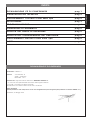 3
3
-
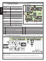 4
4
-
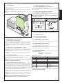 5
5
-
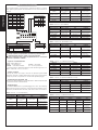 6
6
-
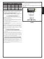 7
7
-
 8
8
-
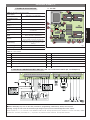 9
9
-
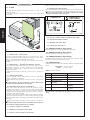 10
10
-
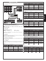 11
11
-
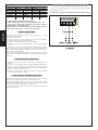 12
12
-
 13
13
-
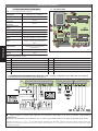 14
14
-
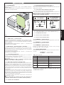 15
15
-
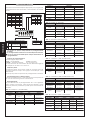 16
16
-
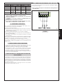 17
17
-
 18
18
-
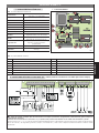 19
19
-
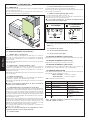 20
20
-
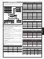 21
21
-
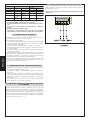 22
22
-
 23
23
-
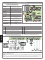 24
24
-
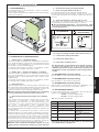 25
25
-
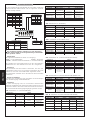 26
26
-
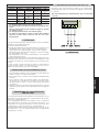 27
27
-
 28
28
-
 29
29
-
 30
30
-
 31
31
-
 32
32


En otros idiomas
- français: Genius GEO 05 Mode d'emploi
- italiano: Genius GEO 05 Istruzioni per l'uso
- English: Genius GEO 05 Operating instructions
- Deutsch: Genius GEO 05 Bedienungsanleitung
Documentos relacionados
-
Genius GEO 05 Instrucciones de operación
-
-
-
-
-
-
-
-
Genius SPRINT382 383 Instrucciones de operación
-