
Owner's Manual
Manual del Propietario
®
ROOM AIR CONDITIONER
ACONDICIONADOR DE AIRE DE VENTANA
Model, Modelo 580. 75151
Sears, Roebuck and Co., Hoffman Estates, IL 60179 U.S.A.
www.sears.com

TABLE OF CONTENTS ........................2
WARRANTY ..............................................2
SAFETY .....................................................3
Important Safety Instructions ...................... 3
ELECTRICAL REQUIREMENTS .......4
INSTALLING THE POWER CORD....4
INSTALLATION ........................................5
Installation Requirements ......................... 5
installation ................................................ 6
How to Install ............................................ 6
Removal from Window ................................. 8
OPERATION .............................................9
How and Why ........................................... 9
Normal Sounds ........................................ 9
Capacity and Running Time ..................... 9
Features ................................................. 10
Using the Air Conditioner ....................... 10
Display ................................................... 11
Remote Control ...................................... 12
MAINTENANCE .....................................13
Air Filter Cleaning ................................... 13
Air Conditioner Cleaning ........................ 13
How to Remove the Front Gdlle .................. 13
How to Replace the Front Grille .................. 13
TROUBLESHOOTING .........................14
Before Calling for Service ...................... 14
ESPANOL ................................................15
MASTER PROTECTION
AGREEMENTS ......................................31
SERVICE NUMBERS ............ Back Cover
FULL ONE YEAR WARRANTY ON
ROOM AIR CONDITIONER
For one year from the date of purchase, when this
air conditioner is operated and maintained for
normal room cooling according to the instructions in
this owner's manual, Sears will repair this air
conditioner, free of charge, if defective in material or
workmanship.
FULL FIVE-YEAR WARRANTY ON
SEALED REFRIGERATION SYSTEM
For five years from the date of purchase, when this
air conditioner is operated and maintained for
normal room cooling according to the instructions in
this owner's manual, Sears will repair the sealed
refrigeration system (consisting of refrigerant,
connecting tubing, and compressor), free of charge,
if defective in material or workmanship.
WARRANTY SERVICE IS AVAILABLE BY
CONTACTING SEARS SERVICE AT
1-800-4-MY-HOME ®.
Warranty coverage applies only to air conditioners
used for non-commercial, private household
purposes.
This warranty applies only while this product is in
use in the United States.
This warranty gives you specific legal rights, and
you may also have other right which vary from state
to state.
Sears, Roebuck and Co., D/817WA,
Hoffman Estates, IL 60179 U.S.A.
-2-

IMPORTANT SAFETY INSTRUCTIONS
The safety instructions below will tell you how to use your room air conditioner to avoid harm to yourself or
damage to your ROOM AIR CONDITIONER.
FOR YOUR SAFETY
Do not store or use gasoline or other flammable
vapors and liquids in the vicinity of this or any other
appliance. Read product labels for flammability and
other warnings.
PREVENT ACCIDENTS
To reduce the risk of fire, electrical shock, or injury
to persons when using your air conditioner, follow
basic precautions, including the following:
• Be sure the electrical service is adequate for the
model you have chosen.
• If the air conditioner is to be installed in a window,
you will probably want to clean both sides of the
glass first. If the window is a triple-track type with a
screen panel included, you may want to remove
the screen completely before installation.
• Be sure the air conditioner has been securely and
correctly installed according to the separate
installation instructions provided with this manual.
Save this manual and installation instructions for
possible future use in removing or reinstalling this
unit.
• Use gloves when handling the air conditioner.
Be careful to avoid cuts from sharp metal fins on
front and rear coils.
[!l'.'_r_vl-'1;t_ll_[qELECTRICAL INFORMATION
The complete electrical rating of your new room air
conditioner is stated on the serial plate. Refer to the
rating when checking the electrical requirements.
• Be sure the air conditioner is properly grounded.
To minimize shock and fire hazards, proper
grounding is important. The power cord is
equipped with a three-prong grounding plug for
protection against shock hazards.
• Your air conditioner must be plugged into in a
properly grounded wall receptacle. If the wall
receptacle you intend to use is not adequately
grounded or protected by a time delay fuse or
circuit breaker, have a qualified electrician install
the proper receptacle.
• Do not run air conditioner with a protective
covering. This could result in mechanical damage
within the air conditioner.
• Do not use an extension cord or an adapter
plug.
_ Avoid fire hazard or electric shock.
Do not use an extension cord or an adapter plug.
Do not remove any prong from the power cord.
3-prong __
grounding
plug
Power su
cord
_3-prong
I _ I grounding
'_ trYPceptWa_/le
--Ground
prong
ENERGY SAVINGIDEAS
• The capacity of the room air conditioner must fit
the room size for efficient and satisfactory
operation.
• Install the room air conditioner on the shady side
of your home. A window that faces north is best
because it is shaded most of the day.
• Do not block air conditioner flow inside with blinds,
curtains, or furniture, or outside with shrubs,
enclosures, or other buildings.
• Close the floor and wall registers and the fireplace
damper so cool air does not escape up the
chimney or into the duct work.
• Keep blinds and drapes in other windows closed
during the sunniest part of the day.
• Clean the air filter as recommended in the
MAINTENANCE section of this manual.
• Proper insulation and weather stripping in your
home will help keep warm air out and cool air in.
• External house shading with trees, plants or
awnings will help reduce the air conditioner's work
load.
• Operate heat producing appliances such as
ranges, washers, dryers, and dishwashers during
the coolest part of the day.
-3-

OBSERVEALL LOCALCODESANDORDINANCES.
DONOT,UNDERANY CIRCUMSTANCES,REMOVE
THE POWERSUPPLYCORDGROUNDPRONG.
ELECTRICALGROUNDISREQUIREDONTHIS
APPLIANCE.
For230/208volt 60 Hz,AC only, 15Afused and
properlygroundedelectricalsupply isrequired.A time
delayfuseor time delaycircuitbreakeris
recommended.Usea dedicatedcircuit,servingonly
thisappliance.
DONOT USEAN EXTENSIONCORD.
x=J
115V~ 230V~
RECOMMENDEDGROUNDINGMETHOD
Foryourpersonalsafety,thisappliancemustbegrounded.
Thisappliancehasapowersupplycordwitha3-prong
groundingplug.Tominimizepossibleshockhazard,the
cordmustbepluggedintoa matinggroundingtypewall
receptacleandgroundedinaccordancewiththeNational
ElectricalCode(ANSI/NFPA70)latesteditionandalllocal
codesandordinances.Ifamatingwallreceptacleisnot
available,itisthepersonalresponsibilityandobligationof
thecustomertohavea properlygrounded3-prongwall
receptacleinstalledbya qualifiedelectrician.
Powercord may include a current interrupter
device. A test and reset button is provided on the
plug case. The device should be tested on a
periodic basis by first pressing the TEST button
and thenthe RESET button. If the TEST button
does not trip or if the RESET button will not stay
engaged, discontinue use of the air conditioner and
contact a qualified servicetechnician.
NOTE: The shape may be different according to its model.
Use Wall Receptacle Power Supply
Standard 125V,
3-wire grounding
receptacle rated
15A, 125V AC
Standard 250V,
3-wire grounding
receptacle r_ed
15A,250V AC
Standard 250V,
3-wire grounding
receptacle rated
20A, 250V AC
Use 15AMP. time
delayfuse or 15 AMP.
circuit breaker.
Use 20AMP. time
delayfuse or 20 AMP.
circuit breaker.
Electrical Shock Hazard
Plug into a grounded 3 prong outlet.
Do not remove ground prong.
Do not use an adapter.
Do not use an extension cord.
Failure to follow these instructions can result in
death, fire, or electrical shock.
You can choose between two methods below according to your window stool shape and preference.
USING SLIT "A"
Fasten the stopper using 1 screw holes, and lead
out the power cord through slit "A".
Power Cord '
-4-
USING SLIT "B"
Fasten the stopper using left screw hole, and rotate
properly to lead the _ower cord out through slit "B".

INSTALLATION REQUIREMENTS
Your air conditioner will install into standard double
hung windows with actual clear opening widths of
29 to 41 inches (737mm to 1041mm) (FIG. 1)
Lower sash must open sufficiently to allow a clear
vertical opening of 18 inches (457mm). Side louvers
and the rear of the air conditioner must have clear
air space to allow enough airflow through the
condenser for heat removal. The rear of the unit
must be outdoors, not inside a building or garage.
__J/- .... Sash
.......i' 29"to_S4t" I/
18"min. _/ , . ,
Inner sillL [ _ wlnaow
,_" "_< :>,_.--Offset
;"_.__;,; Sill
'1 / "'-,I |i-;i- Exterior
"" FIG 1
Interior wall "- .... "
ELECTRICAL SERVICE
Check your available electrical service. The power
supply available must be the same as that shown on
the unit nameplate (found on right side of cabinet).
All models are equipped with a 3-prong service plug
to provide proper service and safe positive
grounding. Do not change plug in any way. Do not
use an adapter plug. If your present wall outlet does
not match your plug, call a qualified electrician to
make the necessary corrections.
SAVE CARTON and this OWNER'S MANUAL for
future reference. The carton is the best way to store
unit during winter or when not in use.
To avoid risk of personal injury, property damage,
or product damage due to the weight of this
device and sharp edges that may be exposed:
•Air conditioners covered in this manual pose an
excessiveweight hazard. Two or more people
are needed to move and install the unit.
To prevent injury or strain, use proper lifting and
carrying techniques when moving unit.
• Carefully inspect location where air conditioner
will be installed. Be sure itwill support the
weight of the unit over an extended period of
time.
• Handle air conditioner with care. Wear
protective gloves whenever lifting or carrying the
unit. AVOID the sharp metal fins of front and
rear coils.
• Make sure air conditioner does not fall during
installation.
INSTALLATION HARDWARE
L
B C D E
F G H I J K
FIG. 2
ITEM NAME OF PARTS Q'TY
A SIDE CURTAIN 2
B SUPPORT BRACKET 2
C SILL BRACKET 2
D LOCK NUT 4
E SCREW: 25/64" 11
F SCREW: 13/16'' 7
G SCREW: 9/16" 5
H M-SCREW 2
I CARRIAGE BOLT 2
J FOAM SEAL 1
K FOAM STRIP 1
L WINDOW LOCKING BRACKET 1
M DRAIN PIPE 1
REQUIRED TOOLS:
• Tight Fitting gloves
• Standard screwdriver
• Phillips screwdriver
• Pliers
• Sharp knife
• 3/8-inch open end wrench or adjustable wrench
• 1/4-inch hex socket and ratchet
• Tape measure
• Electric drill
• 1/4-inch drill bit
-5-

INSTALLATION
Pick a location which will allow you to blow the cold
air into the area you want. Windows used for
installation must be strong enough to support the
weight of the air conditioner. Good installation with
special attention to the proper position of the unit
will lessen the chance that service will be needed.
When cooling more than one room, installation
location is very important. To cool your rooms, cold
air must be blown from the air conditioner in a
straight path.
HOW TO INSTALL
If the air conditioner is blocked by a storm
window frame, see step 16 on page 8 before
beginning to install.
H Remove the screws which fasten the cabinet at
the back and side of the unit. Save side screws.
Discard back screws.
' /..
'_:_ FIG. 3
_ Slide the unit out of the cabinet by gripping the
base pan handle and pull forward while bracing the
cabinet.
FIG. 4
I_'1 Cut the FOAM SEAL (ITEM J) to fit the
underside of the window sash. Peel off the backing
and attach the FOAM SEAL as shown in Fig. 5.
I_1 Insert the side curtain (ITEM A) into the upper guide
and lower guide of the air conditioner. Fasten the curtains
to the unit with screws (ITEM E).
LowerGuide_ _ ITEME FIG. 6
_Open the window. Mark a line on the center of the
window inner sill. Loosely attach the sill bracket (ITEM C)
to the support bracket (ITEM B) using the carriage bolt
(ITEM I) and the lock nut (ITEM D).
ITEM
ITEM I
r'_ Attach the sill bracket to the window sill using the
screws (ITEM F). Carefully place the cabinet on the
window inner sill and align the center of the cabinet
front with the center line marked on the window inner
sill.
/Machine screw
Cabinet_ /and locknut
trackhole ,Outer
/edge of
ITEM windowsill
, /
Carriagebolt..............."
andlocknut Sillbracket FIG. 8
H Using the M-screw (ITEM H) and the lock nut
(ITEM D), attach the support bracket to the cabinet
track hole. Use the first track hole after the sill bracket
on the outer edge of the window sill. Tighten the
carriage bolt and the lock nut. Be sure the cabinet
slants downward 1/4" from level.
CAUTION: Do not drill a hole in the bottom pan. The
unit is designed to operate with approximately 1/2" of
water in bottom pan.
z Sash
FIG. 5
Lowerguide
INDOOR
Cabinet
OUTDOOR
FIG. 9
-6-

_J Pull the bottom window sash down behind the
upper guide until they meet.
NOTE:
• Do not pull the window sash down so tightly that the
movement of sliders is restricted. Attach the cabinet
to the window inner sill by driving the screws (ITEM F)
through the cabinet into window inner sill.
• The cabinet should be installed with a very slight tilt
downward by 1/4" from level.
Window sash Ipper guide
Frame curtain
ITEMF
FIG. 10
_J_ Expand side curtains to fill opening.
Attach each side curtain to the window sash using 4
screws (ITEM G). (FIG. 11)
_1_ Attach the window locking bracket (ITEM L) with
a screw (ITEM G). See FIG. 12.
FIG. 12
Ill DRAINAGE
A drain hole is provided at the rear of the air
conditioner unit. Select a drain method according to
the following.
• Remove the hole rubber from the base-pan.
• Connect a drain elbow of 9/16" inside diameter to
the drain pipe.
• Connect a drain hose of 9/16" inside diameter to the
drain elbow. (Drain hose is not supplied.)
elbow
Drain
hose
FIG. 13
_"_ Slide the air conditioner into the cabinet. (FIG. 14)
CAUTION: For security purposes, reinstall side
screws that were removed in step 1.
Scre_owerCord _ Screw
FIG. 14
_]Cut the foam stripl (ITEM K) to the proper length
and insert between the upper window sash and the
lower window sash. (FIG. 15)
FIG. 15
E]_ Adjust the vent handle before the decorative
front is attached. (FIG. 16)
Straighten the lever, as shown. Pull down part ® to
align with part ®.
FIG. 16
-7-

_r-t FRONT INSTALLATION
Install the front grille(packed separately) onto the
cabinet as follows:
• Hook upper tabs of front grille into slots on the
cabinet top. (FIG. 17)
• Push front grille's tips towards the cabinet in order
to snap side tabs into the cabinet. (FIG. 17)
• Open the inlet grille. (FIG. 18)
• Install the screw (ITEM E) through the front grille.
(FIG. 18)
• Close inlet grille. (FIG. 19)
Front Installation
FIG. 17
ITEM E
Front Installation
FIG. 18
Front Installation FIG. 19
_T_IF AIR CONDITIONER IS BLOCKED BY
STORM WINDOW FRAME
• Ifstorm window presents interference, fasten a 2"
wide wood strip to the inner window sill across the full
width of the sill. The wood strip should be thick
enough to raise the height of the window sill so that
the unit can be installed without interference from the
the storm window frame. See FIG. 20.
Top of wood strip should be approximately 3/4"
higher than the storm window frame to help
condensation to drain properly to the outside.
• Install a second wood strip (approximately 6" long by
11/2"wide and same thickness as first strip) in the
center of the outer sill flush against the back of the
inner sill. Screw the L brackets into this strip.
This will raise the L bracket as shown in FIG. 20.
1 1/2" min.
WOOD STRIP MOUNTED (38mm)
ON TOP OF INNER SILL _J"-I I_= 3/4" ±
"'--._ = I CLEARANCEf
STORM
J I / #v _ WINDOW
INNER IL BRACKET/ L_FRAME
SILL FoWRO0D_TR/PT[_
I I OUTER
% I SILL
INSIDE J J OUTSIDE
FIG. 20
REMOVAL FROM WINDOW
• Turn off and unplug the air conditioner.
• Remove the front grille. See HOWTO REMOVETHE
FRONT GRILLE. Refer topage 13.
• Unscrew the side screws thatyou installed in Step 15.
• Slide the air conditioner out ofthe cabinet.
BE CAREFUL NOT TO DROP IT. Holdonto it firmly the
whole way sliding it out.Once removed, set it safety out
of the way.
• Remove the L bracket from window frame and the sash
seal from between the windows.
• Unscrew the side curtains from the window frame. Fold
them back to the sides of the cabinet.
• Remove screws attaching cabinet to inner sill. Be careful
not to letcabinet fall once screws are removed.
• Remove cabinet from window opening.
• Place air conditioner into cabinet. Reinstall side screws
and Front Grille.
• Place unit and all assembly hardware in air conditioner
shipping carton,and store in clean, dry place.
•Air conditioners covered in this manual pose an
excessive weight hazard. Two or more people
are needed to move and install the unit.
To prevent injury or strain, use proper lifting and
carrying techniques when moving unit.
• When handling the air conditioner, be careful to
avoid cuts from sharp metal fins on front and
rear coils.
• Make sure air conditioner does not fall during
removal.
-8-

HOW AND WHY
Your room air conditioner provides the following
functions to make hot weather living more
comfortable:
• Cools and circulates room air.
• Lowers humidity by removing excess moisture.
• Filters out summertime dust, dirt, and some
airborne impurities.
The air conditioner performs these functions by
drawing room air through a filter which traps dust
and dirt particles. The air then passes over a
cooling coil which refrigerates the air and removes
excess moisture. The same air is then returned to
the room-cooler, drier, and cleaner. Moisture
removed from the room air is carried to the outside
and evaporated.
Your air conditioner is designed to be easy to
operate and to provide plenty of cooling power.
NORMAL SOUNDS FIG.21
Aside from the regular fan motor and compressor
sounds coming from your air conditioner, you will
once in a while hear a pinging sound. This is the
result of moisture being picked up from the air in the
room and thrown against the air conditioner's fan.
This is normal and should not be cause for concern.
Also, do not be alarmed if you hear a slight hissing
or gurgling sound coming from your air conditioner
after it is off. These are normal coolant noises.
CAPACITY AND RUNNING TIME
Proper unit size is important in deciding the desired
comfort for the area you want to cool. An
undersized unit will not have the capability to cool,
leaving the area uncomfortably warm. The proper
size is determined by the number of square feet in
the area to be cooled, indoor and outdoor
temperature and humidity.
Whenever the heat or humidity load is above normal
the air conditioner must run longer and more often
to keep the desired temperature you have selected,
Under heavy heat load conditions the air conditioner
may need to run constantly to keep the temperature
you want.
At times using the MED FAN setting to circulate the
room air may make it comfortable even though the
air is not being cooled. This will decrease your cost
of use.
Compressor
The modern high efficiency
compressor may have a high
pitched hum or pulsating
noise that cycles on and off.
Unit Vibration
The unit may vibrate
and make noise
because of poor wall
or window construction.
Fan
You may hear air
movement from
the fan.
You may hear droplets of water hitting
the condenser causing a pinging or
clicking sound.
FIG. 21
-9-

FEATURES
1 15 6 5
4 32714
J
9 8
11 1210 13 16
FIG. 22
1. Cabinet
2. Vertical Air
Direction Louvers
3. Horizontal Air
Direction Louvers
4. Inlet Grille
5. Air Filter
6. Front Grille
7. Control Board
8. Power Cord
9. Evaporator Coil
10. Condenser
11. Compressor
12. Base pan
13. Brace
14. Upper Guide
15. Curtain
16. Remote Control
USING THE AIR CONDITIONER
To reduce the risk of fire, electric
shock, or injury to persons, read the important
SAFETY instructions section before operating this
appliance
To begin operating the air conditioner after
installation, follow these steps:
1. Plug in the air conditioner. (To prevent electrical
hazards, do not use an extension cord or an
adapter plug.)
2. Set the exhaust vent to the CLOSE position.
3. Set the TEMP Control to the coolest setting.
4. Set the MODE control at the highest COOL level.
5. Adjust the louvers for comfortable air flow.
6. Once the room has cooled, adjust the TEMP and
Mode Control to the setting you find most
comfortable.
NOTE : If the air conditioner is turned off, wait 3
minutes before restarting. This allows pressure
inside the compressor to equalize. Failure to wait 3
minutes before restarting may cause inefficient
operation.
If you move the TEMP Control to a warmer, then
immediately back to a cooler setting, the unit will
shut off. Wait 3 minutes before restarting.
VENT CONTROL
The Vent Control allows the air conditioner to
either recirculate inside air (CLOSE) or exhaust
air te the outside (OPEN). (FIG. 23)
• The CLOSE position is used when maximum
cooling is desired. It may also be used for air
recirculation without cooling when the air
conditioner is set in the FAN position.
• The OPEN position removes stale air from the
room and exhausts it to the outside. Fresh air is
drawn into the room through your home's
normal air passages.
• The OPEN or CLOSE position can be used with
any fan selection.
PULL OPEN / PUSH CLOSE
FIG. 23
-10-

DISPLAY
FAN SPEED
• Every time you push this button, it advances the setting as follows: {High _Low _Med _High}
REMOTE CONTROL SIGNAL
RECEIVER
TEMPERATURE SETTING
• This button can automatically control the
temperature of the room.
The temperature can be set within a range
of 60°F to 86°F by increments of 1°F.
POWER
(-TIMER
- SHUT-OFF TIME
• You will usually use shut-off time while you sleep.
• If unit isrunning,Timer sets numberof hours untilshut-off.
• Everytime you pushTimerbutton, it advancesthe Timersetting
asfollows: 1 Hour * 2Hours ...... 12 Hoursmaximum.
• Toturn the airconditionerON, push the
button.
Toturn the air conditioner OFF, push
the button again.
• This button takes priority over any other
button.
• When you first turn it on, the air conditioner is
on the High coolmode andthe Temp.at 72°F.
- START TIME
• If unit isoff, Timer setsnumberof hours beforeunit starts.
• Everytime you pushTimerbutton, it advancesthe Timersetting asfollows: 1 Hour _2 Hours ....... 12Hours
maximum.
MODE
- Every time you push this button, it will shift among COOL, ENERGY SAVER and FAN.
- ENERGY SAVER:
• The fan stops when the compressor stops cooling.
Approximately every 3 minutes the fan will turn on and check the room air to determine if cooling is
needed.
In failure of electric power, the unit runs as previous setting operation. J
HORIZONTAL AIR DIRECTION CONTROL VERTICAL AIR DIRECTION CONTROL
The horizontal air direction is adjusted by moving The vertical air direction is adjusted by moving the
horizontal louvers up and down with your fingertips.
the vertical louvers right and left with your (FIG. 25)
fingertips. (FIG. 24)
FIG. 24 FIG. 25
-11 -

REMOTE CONTROL
NOTE: The Remote Control will not operate properly if strong light shines on the sensor window of the Air
Conditioner or if there are obstacles between the Remote Control and the Air Conditioner.
Every time you push button, you will hear a beep from the Air Conditioner.
POWER
• To turn the air conditionerON,push the button. To turn the airconditionerOFF, push the
button again. Thisbutton takes priority overany other button.
When you first turn it on,the air conditioner ison the High cool mode andthe Temp. at
72OF
TEMPERATURE SETTING
• This button can automatically control the temperature of the room.
The temperature can be set within a rangeof 60°F to 86°F by increments of I°F.
FAN SPEED
• Everytime you push this button it advances the setting as follows:
(High _Low _Med _High)
TIMER
- SHUT-OFF TIME
• You will usally use shut-off time while you sleep.
• Ifunit is running, Timer sets number of hours until shut-off.
• Everytime you push Timer button, it advances the Timer setting as follows: 1 Hour
2 Hours ...... * 12 Hoursmaximum.
- START TIME
• Ifunit is off, Timer sets number of hours before unit starts.
• Everytime you push Timer button, it advances the Timer setting as follows: 1 Hour
2 Hours _..... * 12Hoursmaximum.
FAN SPEED
TIMER MODE
MODE
- Every time you push this button, it will shift among COOL, ENERGY SAVER and FAN.
- ENERGY SAVER
• The fan stops when the compressor stops cooling.
Approximately every 3 minutes the fan will turn on and check the room air to determine if cooling is needed.
HOW TO INSERT BATTERIES INTO REMOTE CONTROL
1. Remove the cover from the back of the remote
controller.
• Openthe cover according to the arrow directionon the
cover.
2. Insert two batteries.
• Be sure that the (+) and (-) directions are correct.
• Be sure that both batteries are new.
3. Re-attach the cover.
• Do not use rechargeable batteries.
Such batteries differ from standard dry cells in shape,
dimensions, and performance.
• Remove the batteries from the remote controller if the air
conditioner is not going to be used for an extended
length of time.
-12-

AIR FILTER CLEANING
The Air Filter will become dirty as it removes dust
from the inside air. It should be washed at least
every 2 weeks. If the Air Filter remains full of dust,
the air flow will decrease and the cooling capacity
will be reduced, possibly damaging the unit.
• Pull the inlet grille forward, grasping both tabs,
then pull out the air filter. (FIG. 26)
• Wash the Air Filter under the faucet with warm
water. Be sure to shake off all the water before
replacing the filter. (FIG.27)
FIG. 26
FIG. 27
AIR CONDITIONER CLEANING
Clean the front grille and inlet grille by wiping with a
cloth dampened in a mild detergent
solution.(FIG.28)
The cabinet may be washed with mild soap or
detergent and lukewarm water, then polished with
liquid appliance wax.
To ensure continued peak efficiency, the condenser
coils (outdoor side at the unit) should be checked
periodically and cleaned if they become clogged
with soot or dirt from the atmosphere. Brush or
vacuum exterior coils to remove debris from fins.
FIG. 28
HOW TO REMOVE THE FRONT
GRILLE
• Open the inlet grille downward.
• Remove the screw securing the Front Grille.
• Push the grille up from the bottom and pull the top
of the grille away from the case to lift the top tabs
out of their slots.
HOW TO REPLACE THE
FRONT GRILLE
Attach the front grille to the cabinet by inserting the
tabs on the grille into the slots on the front of the
cabinet. Push the grille in until it snaps into place.
FIG. 30
3 -
/

BEFORE CALLING FOR SERVICE
Check the following list to be sure a service call is really necessary. A quick reference to this manual may
help you avoid an unneeded service call.
THE AIR CONDITIONER WILL NOT OPERATE.
Check if...
Wall plug disconnected.
House fuse blown or circuit breaker tripped.
Power is OFF.
Unit was turned off and then on too quickly.
TEMP Control set warmer than room temperature.
The current interrupter device is triped
Then...
Push plug firmly into wall outlet.
Replace fuse with time delay type or reset circuit breaker.
Push the power button.
Set unit offand wait 3 minutes before restarting.
Set TEMP Control to lowertemperature.
Press the RESET button located on the power cord plug
If the RESET button will not stay engaged, discontinue use of the
air conditioner and contact a qualified service technician.
AIR FROM UNIT DOES NOT FEEL COLD ENOUGH.
Check if...
FAN SPEED set at LOW.
TEMP Control set too warm.
Room temperature below 70°F (21°C).
Temperature sensing tube touching evaporator coil,
located behind front grille.
Then...
Push FAN SPEED button to set at HI.
Set TEMP Control to lowertemperature.
Cooling may not occur until room temperature rises above 70°F (21°C)
Straighten tube away from evaporator coil.
THEAIRCONDmONERCOOLING,BUTROOMISTOOWARM-ICE FORMINGONCOOLINGCOILBEHINDFRONTGRILLE.
Check if... Then...
Outdoor temperature below 70°F (21°C) To defrost the coil, set the MODE to FAN.
Air filter may be dirty. Clean air filter. Refer to Maintenance section of owner's manual.
TEMP Control set too cold for night-time cooling. To defrostthecoil,setthe MODE to FAN or "High Cool" with the
TEMP controlto hiqhertemperature.
THE AIRCONDITIONERCOOLING,BUT ROOMISTOO WARM.
Check if... Then...
Dirtyairfilter- airrestricted. Cleanairfilter.Referto Maintenancesectionofowner'smanual.
TEMPControlsettoowarm. SetTEMPControlto lowertemperature.
Frontofunitisblockedbydrapes,blinds,furniture,etc. Clearblockagein frontofunit.
Airdistributionisrestricted.
Doors,windows,registers,etc.open.Coldairescapes. Closedoors,windows,registers,etc.
Unitrecentlyturnedon inhotroom. Allowadditionaltimetoremovestoredheatfromwalls,ceiling,floor,andfurniture.
THE AIR CONDITIONER TURNS ON AND OFF RAPIDLY.
Check if... Then...
I Outsidetemperatureisextremelyhot. I SetFANSPEEDonHItobringairpastcoolingcoilsfaster. I
NOISE WHEN UNIT IS COOLING.
Check if... Then...
Soundoffanhittingwaterfromthemoistureremovalsystem. Thisisnormalwhenhumidityishigh.Closedoors,windows,andregisters.
Windowvibration- poorinstallation. Refertoinstallationinstructionsor checkwithinstaller.
WATER DRIPPING INSIDE ROOM WHEN UNIT IS COOLING.
Check if... Then...
Theairconditionerisimproperlyinstalled. Tiltinstallationairconditionerinstructionsslightlyortochecktheoutsidewithinstaller,toallowwaterdrainage.Referto
WATER DRIPPING OUTSIDE WHEN UNIT IS COOLING.
Check if... Then...
Theunitis removinglargequantitiesofmoisture Thisisnormalduringexcessivelyhumiddays.
fromhumidroom.
-14-

INDICE DE MATERIAS ............................. 15
GARANT_ ................................................ 15
SEGURIDAD .............................................. 16
Importantesinstruccionesdeseguridad .....16
REQU ERIMIENTOS ELC:CTRICOS ......... 17
INSTALAClON DEL CABLE ELC:CTRICA...17
INSTALAClON ........................................... 18
Requerimientos para instalaci6n .......... 18
Installaci6n ............................................ 19
Como instalarlo ..................................... 19
La eliminacion de la ventana ................. 21
OPERACI()N .............................................. 22
Como y por que ..................................... 22
Sonidos normales .................................. 22
Capacidad y tiempo de funcionamiento ...22
Caracteristicas ..................................... 23
Uso del equipo de aire acondicionado ..23
Despliegue ............................................ 24
Control remoto ....................................... 24
MANTENIMIENTO .................................... 26
Limpieza del filtro del aire ...................... 26
Limpiezadelequipode aireacondicionado....26
C6mo sacar la rejilla frontal ................... 26
C6mo a reemplaza el grille anterior ......26
CORRECClON DE FALLAS ...................... 27
Antes de LlamarparaServicio...................... 27
ACUERDOS DE PROTECClON
ESPEClALIZADA ...................................... 31
PARA PEDIR SERVIClO ....Cubierta Trasera
GARANTJA DE UN ANO POR EL
EQUIPO DE AIRE ACONDICIONADO
DE HABITACION
Durante un aSocompleto a partir de la fecha de
compra, si este equipo de aire acondicionado recibe
mantenimiento y se utiliza para el enfriamiento
normal de habitaci6n segun las instrucciones
indicadas en este manual del propietario, Sears
reparara gratuitamente este equipo de aire
acondicionado, si tiene algun defecto en materiales
o fabricaci6n.
GARANTJA TOTAL DE ClNCO ANOS
POR EL SlSTEMA DE REFRIGERAClON
HERMI_TICAMENTE SELLADO
Durante cinco aSos a partir de la fecha de compra,
si este equipo de aire acondicionado recibe
mantenimiento y se utiliza para el enfriamiento
normal de habitacion segun las instrucciones
indicadas en este manual del propietario, Sears
reparara gratuitamente el sistema de refrigeracion
hermeticamente sellado (que consiste en el agente
refrigerante, los tubos de conexi6n y el compresor),
si tiene algun defecto en materiales o fabricacion.
EL SERVIClO DE GARANTIA ES
DISPONIBLE CONTACTANDO AL SERVICIO
SEARS AL 1-800-4-MY-HOME ®
La proteccion de garantia cubre unicamente a
los equipos de aire acondicionado usados para
uso domestico y no para uso comercial.
Esta garantia solo tiene validez mientras el
producto se este usando en los Estados
Unidos.
Esta garantia le da derechos legales
especificos y usted puede tener otros
derechos que varian de estado en estado.
Sears, Roebuck and Co., D/817WA,
Hoffman Estates, IL 60179 U.S.A.
-15-

IMPORTANTES INSTRUCCIONES DE SEGURIDAD
Las siguientes instrucciones de seguridad le indicaran c6mo usar su equipo de aire acondicionado de
habitacion para evitar daSos para usted mismo y para su EQUIPO DE AIRE ACONDICIONADO.
POR SU SEGURIDAD
No almacene ni use gasolina u otros vapores y
Ifquidos inflamables cerca de este o cualquier otro
electrodomestico. Lea las etiquetas de los
productos para ver si contienen advertencias sobre
el caracter inflamable de los mismos y otras
advertencias.
PARA PREVENIR ACCIDENTES
Para reducir el riesgo de incendios, descargas
electricas o lesiones personales al usar su equipo
de aire acondicionado, tome las precauciones
basicas, entre las que estan las siguientes:
• AsegQrese de que la alimentaci6n electrica sea la
apropiada para el modelo que usted ha elegido.
• Si el equipo de aire acondicionado debe instalarse
en una ventana, a usted probablemente le
conviene limpiar primero ambos lados del vidrio.
Si la ventana es del tipo de tres paneles con un
panel incluido de pantalla, le conviene sacar la
ventana completamente antes de la instalacion.
• AsegQrese de que el equipo de aire
acondicionado ha sido instalado correctamente y
con seguridad segun se seSala en las
instrucciones separadas de instalacidn que vienen
en este manual. Conserve este manual y las
instrucciones de instalaci6n para usarlos
posiblemente en el futuro al sacar o volver a
instalar esta unidad.
• Use guantes al manejar el equipo de aire
acondicionado, tenga cuidado para evitar cortadas
con las afiladas aletas metalicas que se hallan en
los serpentines frontales y posteriores.
INFORMACION ELECTRICA
En la placa de serie del fabricante se indica cual es
la capacidad electrica nominal completa de su nuevo
equipo de aire acondicionado para habitaci6n. Consulte
esta placa cuandovaya averificar los requerimientos
electricos.
• Asegurese de que el equipo de aire acondicionado
tenga una conexi6n correcta a tierra. Para reduciral
minimo los riesgos de descargas electricas e incendio,
esimportante conectar el equipo correctamente atierra.
El cordon de alimentacion electrica esta equipado con
un enchufe de tres espigas con conexion a tierra para
protegerle contra riesgos dedescargas electricas.
• Su equipo de aire acondicionado debe enchufarse en
una toma de corriente de pared que tenga una conexi6n
correcta a tierra. Si la toma de corriente de paredque
usted piensa usar no esta conectada correctamente a
tierra o no esta protegidacon un fusible de accion
retardadao con un interruptorde circuito, haga que un
electricista calificadole instale la toma de corriente de
pared en forma correcta.
• No ponga a funcionar el equipo de aireacondicionado
con una cubiertaprotectora exterior encima. Esto podrfa
ocasionar da_os mecanicos dentro delaire
acondicionado.
• No use un cable de extension ni un enchufe
adaptador.
Evitelos peligrosde incendiosy
descargaselectricas.No useun cablede extensi6nni un
enchufeadaptador.Noelimineninguna delasespigas
delenchufedelcordonde alimentacionelectrica.
Toma de corriente
de pared con --
conexi6n a tierra.
Bajo ninguna
circunstancia
corte, quite o evite
el use de la
conexi6n a tierra
de esta clavija.
Cablede
I _%'_ alimentaci6n
"_ I \\_Jh conclavija
I dotada,de
I I clinlrX ° e3
'_ terminales.
- Terminalde
conexi6natierra.
IDEAS PARA AHORRAR ENERGIA
• La capacidad del equipo de aire acondicionado
debe corresponder al tamaSo de la habitacidn
para el funcionamiento eficiente y satisfactorio del
equipo.
• Instale el equipo de aire acondicionado de
habitacion en el lado sombreado de su hogar. Una
ventana orientada hacia el norte es la mejor
porque tiene sombra la mayor parte del dia.
• No bloquee el aparato de aire acondicionado
tapandolo con persianas, cortinas, muebles o en
el exterior con arbustos, recintos u otros edificios.
• Cierre el regulador de tiro de la chimenea, las
rejillas de calefaccidn del piso y la pared, de tal
modo que el aire frio no se escape ni por la
chimenea ni pot los conductos.
• Mantenga las persianas y las cortinas de otras
ventanas cerradas durante la parte mas soleada
del dia.
• Limpie el filtro del aire como se recomienda en la
seccidn "MANTENIMIENTO" de este manual.
• El aislamiento correcto y las juntas hermeticas en
puertas y ventanas en su hogar le ayudaran a
mantener el aire caliente afuera y el aire frio
adentro.
• AI darle sombra externamente a la casa con
arboles, plantas o toldos ayudara a reducir la
carga de trabajo del equipo de aire acondicionado.
• Opere los aparatos que producen calor como, por
ejemplo, hornos, lavadoras, secadoras y
lavaplatos durante la parte mas fria del dfa.
-16-

RESPETETODOSLOSCODIGOSY REGLAMENTOS.
BAJONINGUNACIRCUNSTANCIACORTE,QUITE0
EVITEELUSODELACONEXIONATIERRADEESTA
CLAVIJA.
ESTEAPARATONECESITASERCONECTADOATIERRA.
Serequiereunaalimentaci6nelectricaCA,adecuadamente
conectadaatierraconunfusiblede15A,de60Hzyde
230/208V. Serecomiendaunfusiblederetardooun
disyuntordecircuitoquealimentesolamentea esteaparato.
NOUSECABLEELECTRIC0DEEXTENSION.
MI_TODORECOMENDADODECONEXIONATIERRA
Persupropiaseguridadesteaparatodebeconectarseatierra.Este
aparateviensequipadoconuncabledealimsntaci6nyunaclavijade
tresterminalss.Parareduciralm&ximeelpsligredechequeelectrico,
elcabledebesstarconectadoaunaconexi6ndeparedconconexi6n
atisrra,yestaconexi6ndebehacersedeacuerdoconla_Jltima
sdici6ndelC6digoElectricoNacional(ANSI/NFPA70),asfcomocon
losc6digosyreglamsntoslocales.Sinoexisteunaconexi6nde
paredadecuada,elclientstisnelarespensabilidadylaobligaci6nde
mandarinstalar,conunelectricistacalificade,unaconexi6ndepared
adscuadadetresterminalesconconexi6natierra.
115V~ 230V~
Elcabledealimentaci6npuedeincluirundispositivo
interrupterdecorriente.Lacarcasadelenchufecuenta
conunbot6ndepruebayotrodereinicio.Eldispositivo
debecomprobarseperi6dicamentepresionando
primeroelbot6nTESTydespuesRESET.
Sielbot6nTESTnosedesconectaosielbot6n
RESETnopermaneceactive,suspendaelusedelaire
acondicionadoyp6ngaseencontactoconuntecnico
deserviciocualificado.
NOTA:La forma puede ser diferente segun su modelo.
Utiliceel enchufedela pared Consumo de Energia
_) tandard 125V,
enchufe de 3
Lfneas de
15A, 125V AC Utilice un fusible de
15AMP. o un
Standard 250V, Interruptor de 15AMP.
enchufe de 3
Lfneas de
15A, 250V AC
Standard 250V,
enchufe de 3 Utilice un fusible de
Lfneas de 20AMP. o un
2OA, 250V AC Interruptor de20AMP.
A ADVERTENCIA
Peligrode choque electrico
Conecte en unaconexion de pared de 3terminales
No quite la terminal de conexion atierra
No use adaptadores
No use cable electrico de extension
Si no se siguen estas instrucciones, puede ocasionarse
la muerte, un incendio oun cheque electrico.
Puede escoger entre los dos metodos abajo descritos de acuerdo a la forma del taburete de suventana y su preferencia.
/
UTILIZANDO LA RANURA "A"
Apreteelobturadorusando1hoyosdetornillo,ysaqueelcable
electricoatravesdelaranuraA.
-17-
UTILIZANDO LA RANURA "B"
Apreteelobturadorusandoelhoyoizquierdodetornillo,ygire
apropiadamenteparasacarelcableelectricoatravesdelaranura"B".
[0

REQUERIMIENTOS PARA
INSTALACION
Su equipo de aire acondicionado se instalara en
ventanas estandar de doble panel con anchos de
abertura libre de 737 mm a 1041 mm (29 a 41
pulgadas). (Figura 1)
El marco inferior debe abrirse Io suficiente para
permitir una abertura vertical libre de 457 mm (18
pulgadas). Las rejillas desviadoras laterales y la
parte posterior del equipo de aire acondicionado
deben tenet un espacio libre de aire para permitir
suficiente flujo de aire a traves del condensador
para asf eliminar el calor. La parte posterior de la
unidad debe quedar al aire libre, no dentro de un
edificio o garaje.
............._ ...................." Banda
IIt-T29to41-t
18"rain. . Ventana
l, Rep sJ l
II 1
(,,t__] .'___Antepecho
I 21 f*-! Exteri°r
Pared in_tte;_o!....... "1/" Figura,
SERVICIO ELECTRICO
Compruebe cu_.lesla alimentacion electrica que Ilega a
su domicilio. La alimentaci6n electrica disponible debe
ser la misma que se muestra en la placa del fabricante de
la unidad (que se halla en el lado derecho del gabinete de
corriente alterna).
Todos losmodelos est_.nequipados con un enchufe de
tres espigas para suministrar un servicio correcto y una
conexi6n a tierra segura y positiva. No cambie el enchufe
de ninguna forma. No use unenchufe adaptador. Si su
toma de corriente de paredactual no puede usarse con el
enchufe del equipo, Ilamea un electricista calificado para
que efectue las correcciones necesarias.
CONSERVE LA CAJA y este MANUAL DEL
PROPIETARIO para que le sirva como referencia en el
future. La caja es la mejor manera de conservar la unidad
durante el inviernoo cuando no est,. en use.
INSTALACION PIEZAS DE MONTAJE
L
B C D E
F G H I J K
Figura 2
iTEM NOMBRE DE LAS PIEZAS CANTIDAD
A PANEL DE GUfA 2
B SOPORTE 2
C SOPORTE DE ANTEPECHO 2
D CONTRATUERCA 4
E TORNILLO: 25/64" 11
F TORNILLO: 1 3/16" 7
G TORNILLO: 9/16" 5
H TORNILLO M 2
I BULON 2
J CINTA DE ESPUMA 1
K CINTA DE ESPUMA 1
L SOPORTE DE CERRADURA 1
M TUBO DE DRENAJE 1
HERRAMIENTAS REQUERIDAS
Paraevitarel riesgode lesionespersonales,danosasu
propiedad,o danosal productodebidoal pesodeeste
equipoy losfilosaqueseranexpuestos:
• Elaireacondicionadodelquesehablaen estemanual
afirmapeligrodepesoexceslvo.
Dosomaspersonasse requiereparamovereinstalarla
unidad.Paraevitarheridasoagotamlento,usetecnicas
apropiadasparalevntary moverlaunidad.
•Cuidadosamenteinspeccioneel hgardondeel aire
acondicionadoserapuesto.Aseguresequeel hgar
sostengaelpesodelaunidadsobreunperiodode
tiempoprolongado.
•Mantengasuaireacondicionadoconcuidado.Use
guantesprotectorescuandolevanteomuevalaunidad.
EVlTElasaletasfilosasde metalenelserpentin
delanteroy deatras.
•Aseguresequeelaireacondicionadonosecaiga
durantelainstalacion.
• Guantes apretados
• Destomillador normal
• Destomillador Phillips
• Pinsas
• Cuchillo filoso
• Llave inglesa o Ilave abierta de 3/8"
• Llave hexagonal de cubo y trinquete de 1/4 de
pulgada
• Cinta para medir
• Taladro electrico
• Broca de taladro de 1/4"
-18-

INSTALACION
Escoja un lugar que le permita Ilevar el aire frb al Area
que desea. Las ventanas que se usen para la
instalaci6n deben tener la resistencia suficiente para
soportar el peso del equipo de aire acondicionado. Una
buena instalaci6n con atenci6n especial a la correcta
posici6n de la unidad disminuira la probabilidad de que
sea necesario efectuar reparaciones.
Cuando se desea enfriar mas de una habitaci6n, la
instalaci6n es muy importante puesto que el aire fifo no
dobla esquinas. Para enfriar sus habitaciones, el aire
frio debe desplazarse desde el equipo de aire
acondicionado en una trayectoria recta.
COMO INSTALARLO
H Saque los tornillos que aseguran el gabinete en
ambos lados yen la parte posterior.
Figura 3
_"_ Deslice la unidad sacandola de su gabinete
agarrando el asa del recipiente de la base y tirando
de ella hacia delante mientras sostiene el gabinete.
Figura 4
_'_ Corte la cinta de espuma (iTEM J) a la
extension apropiada.
Despegue el refuerzo y peguelo en el lado de abajo
del marco de la ventana.
_"1_ Insertelospanelesdegufa(iTEM A) en laguiasuperior
y lasguias de marcodelequipode aireacondicionado.
Sujetelascortinasen la unidadconlostornillos(iTEM E)
iTEME
Gufa mas baja
iTEME Figura 6
_"_ Abra la ventana. Marque una l/neaen el centro de la
repisade la ventana entre losmoldes de tope lateralde la
ventana. Fije sin apretarel soportede antepecho (iTEM C)
al otrosoporte (iTEM B) usandoel bul6n(fTEM I) y la
contratuerca (iTEM D).
iTEM I
"_iTE M D
Figura 7
_'_ Fije el soporte de antepecho al antepecho a la
ventana usando los tornillos (fTEM F).Coloque
cuidadosamente el gabinete sobre la repisa de la ventana
y alinee lamarca del centro en la parte frontal inferior con
la I[nea central marcada en la repisa de la ventana.
/
/Tornitlo parametalesy /
_contratuerca
1
Bordeexteriordel
_antepecho deta
ventana
./ (ITEMF)
Bul6ny contratuerca_ \ Figura 8
Soportedeantepecho
U Usandoel tornillo M (iTEM H) y la contratuerca
(ITEMD), fije elsoporte al orificio decarril del gabinete.
Useel primerorificio de carrildespues del soportede
antepechoen el hordeexterior delantepecho de ventana.
Aprieteel bul6ny la contratuerca.Asegt]rese de que el
gabinete seincline hacia fuera 1/4 degota usando el niveL
CUIDADO: Noperfore un orificioen el recipienteinferior.
La unidad esta dise_adaparaoperar con aproximadamente
1/2pulgadade agua en el recipienteinferior.
J Banda
Figura 5
Guia inferior
Gabinete
INTERIOR EXTERIOR Figura 9
-19-

f_l Tire del marco inferiorde la ventana hacia abajo
detr_.sde la gufa superior hasta que seencuentre la gufa
con el marco.
NOTA:
• No tire del marco de laventana tan hacia abajo que
restrinja el movimiento de las correderas. Fije el
gabinete a la repisa de laventana atornillando los
tornillos (ITEM F)a traves del gabinete en la repisa de
la ventana.
• El gabinete debe instalarse 1/4 de gota deel nivel, hecia
abajo y hacia fuera.
Marco de
deCinta
espuma
Gabinet
Encuadre
cortina
Figura 10
_'_ Extienda el panel hasta Ilenar el hueco.
Fije cada panel gufa en el marco de la ventana usando
dos tornillos (ITEM G). (Figura 11)
ITEM G
lower Guide
/1 Figura 11
Se debe instalar el asa antes de fijar el frente
decorativo. (Figura 12)
Figura 12
_IDREANJE
En la parteposteriorde la unidadde aireacondicionadohay
un orificio de drenaje. Seleccione un metodo de drenaje
seg{Jnlassiguientesinstrucciones:
• Saque delrecipientedebase lagoma delorificio.
• Conecteuna manguerade drenajede 9/16"de pulgadade
di_.metrointernoal tubede drenajecomesemuestra.
- 20 -
• Conecteun codo de tubode 9/16" de pulgadade diametro
interno al tubo de drenaje, conecte seguidamente una
manguera de drenaje de 9/16" de pulgada de di_.metro
internealcodedeltubocomose muestra.(Elequipode aire
acondicionadonovienecon unamanguerade drenaje.)
'/',i
Manguera
de drenaje Manguera de drenaje
Figura 13
_ Deslice el chasis hacia el interior del gabinete.
(Figura 14)
CUIDADO: Con fines de seguridad, vuelva a
instalar los tornillos en los lades del gabinete.
Tornillo
Cord6n de
electrica
]-orF_u ra 14
Corte la junta hermetica de espuma(fTEM K)
para que tenga la Iongitud apropiada e insertela
entre el marco superior y el marco inferior de la
ventana. (Figura 15)
[_ Figura 15
E]_ Ajuste el asa antes de fijar el frente decorative.
(Figura 16)
Enderence el kit de ventilacion come se indica,
halando hacia debajo de la parte ® Ilevandola en la
linea horizontal con la parte ®.
Figura 16

INSTALACION FRONTAL
Instale la rejilla frontal con el gabinete de la
siguiente manera:
• Tire de la rejilla frontal hacia abajo desde la parte
superior del gabinete. (Figura 17)
• Empuje las puntas de la rejilla frontal hacia el
gabinete para insertar las leng etas de la rejilla
dentro del gabinete. (Figura 17)
• Abra la rejilla de entrada. (Figura 18)
• Apriete el tornillo (ITEM E) a traves de la rejilla
frontal fijandolo al recipiente de base (Figura 18)
• Cierre la rejilla de entrada. (Figura 19)
Instalaci6n frontal
Figura 17
ITEM E
Instalaci6n frontal
Figura 18
Ir,' [_lJ ID7:1Die]
Instalacion frontal Figura 19
_'_SI EL ACONDIClONADORDEAIREESTABLOOUEADO
POREL MARCODELACONTRAVENTANA
• Si la contraventana interfiere fije un liston de madera de
2" de ancho al alfeizar interiorde la ventana, que
atraviese la anchura total del alfeizar. El liston de
madera debe ser suficientemente grueso para levantar
la altura del alfeizar de laventana de tal manera que la
unidad pueda ser instalada sin la interferencia del marco
de la contraventana. Vea la Figura 20.
La parte superior del liston de madera debe ser
aproximadamente 3/4" mas alto que el marco de la
contraventana o el list6nde madera (fuera de la casa)
para que el vapor emanado de la unidad pueda drenar
adecuadamente hacia el exterior.
• Instaleunsegundolist6nde madera (deaproximadamente
6" de largoy 1"de anchoy del mismogrosor delprimer
liston)en el centrodelalfeizarexterior niveladocon la
parte posterior delalfeizarinterior.Atornillelos soportesL
entre lafaja. Esto levantaraelsoporteL comosemuestra
en la Figura20.
1 1/2" min.
38mm
FRANJA DE MADERA _1 I-,,,,=-3/4-PULG
MONTADASOBRE _ r. ] DE SEPARACION '_
LA PARTE SUPERIOR "_'_'JF.777]I _,.,|
DEL DESCANSO _ i '_'_'_"_,_'_',.,,Ji
INTERIOR ____._]-",o, VENTANA DE _'
/ ]SUPPORT d v_ HOJA DOBLE
ANTEPECHO ] EN L / L
L_,_ _L_ I_C_H_O_L ] ANTEPECHO
INTERIOR ] ] EXTERIOR
Figura 20
La ELIMINAClONDE laVENTANA
• Apagueel acondicionadoraereo.
• Quiteelgrilleanterior.VeaCOMOAREEMPLAZAELGRILLE
ANTERIOR.Refieraseapa.gina37.
• Destornilleel tornillodelladoqueustedinstaloenel Paso12.
• Desliceelacondicionadoraereofueradelgabinete.TENGA
CUIDADOnoA laGOTA.TengaenIofirmementelamanera
enteraquedeslizafuera.Unavet quitado,Iopusoseguridad
fueradelamanera.
• QuiteelparentesisLdelmarcodeventanayel sellode banda
deentreelwindows.
• Destornillelas cortinasdelladodelmarcodeventana.
Doblelosapoyanalosladosdelgabinete.
• Quiteeltornilloconectargabinetealalfeizalinterior.Tengacuidado
noapermiti6quegabinetefallaraunavettornillossequitan.
• Quitegabinetede abrirdeventana.
• Coloqueelacondicionadoraereoenel gabinete.Vuelvaa
instalarlostornillosdelladoy GrilleAnterior.
• Coloquelaunidady todaferreter[ade laasambleaenel
cartonaereodelenv[odelacondicionador,yen latiendaen
limpia,secaellugar.
• El aire acondicionado del que se habla en este
manual afirma peligro de peso excesivo.
Dos o mas personas se requiere para mover e
instalar la unidad. Para evitar heridas o
agotamlento, use tecnicas apropiadas para
levntar y mover la unidad.
• AI manejar la unidad, tenga cuidado para evitar
cortarse con las alertas met,_licas afiladas que
est&n en los serpentines frontal y posterior.
• Asegurese que el aire acondicionado no se
caiga durante la instalacion.
-21 -

COMO Y POR QUI
Su equipo de aire acondicionado de habitaci6n
brinda las siguientes funciones para hacer que la
vida en climas c_.lidos sea mas confortable:
• Enfria y hace circular el aire por la habitacion
• Disminuye la humedad eliminando la humedad
excesiva.
• Filtra el polvo, el sucio y algunas impurezas
transportadas en el aire del clima veraniego.
El equipo de aire acondicionado realiza estas
funciones haciendo pasar el aire del medio
ambiente a trav@s de un filtro que atrapa las
particulas de polvo y sucio. El aire pasa entonces
pot un serpent[n de enfriamiento que refrigera el
aire y elimina el exceso de humedad. El mismo aire
regresa entonces al enfriador, secador y limpiador
del aire del ambiente. La humedad extraida del aire
ambiente es Ilevada al exterior y evaporada.
Su aire acondicionado esta diseSado para operar y
suministrar una enorme potencia de enfriamiento.
SONIDOS NORMALES Figura 21
Ademas de los sonidos regulates del motor del
ventilador y el compresor que salen de su equipo
de aire acondicionado, usted escuchara de vez en
cuando un sonido metalico. Este sonido es
producido per la humedad que es recogida del aire
en el ambiente yes lanzada contra el ventilador del
equipo de aire acondicionado. Esto es algo normal
que no debe set motive de preocupaci6n. De igual
modo, no se alarme si usted escucha un ligero
sonido de silbido o borboteo proveniente de su
equipo de aire acondicionado despu@s que Io
apaga. Estos son ruidos normales del refrigerante.
CAPACIDAD Y TIEMPO DE
FUNCIONAMIENTO
AI decidir cual debe ser la comodidad deseada para el
&rea que usted quiere enfriar, es importante
determinar el tamafio correcto de la unidad. El tamaho
adecuado es determinado por el nQmero de metros
cuadrados que tiene el area que se desea enfriar, asf
como por la temperatura interior y exterior y por la
humedad.
Siempre que la carga t@rmicadel ventilador est@por
encima de Io normal, el equipo de aire acondicionado
debe funcionar m&s tiempo para mantener la
temperatura deseada que usted ha seleccionado. Bajo
condiciones de una carga t@rmicamuy pesada, puede
ser necesario que el equipo de aire acondicionado
funcione constantemente para mantener la
temperatura deseada.
En ocasiones, el use de HIGH FAN para hacer circular
el aire por la habitaci6n hace que el ambiente sea ma.s
confortable aun cuando el equipo no est@enfriando el
aire. Mientras mas tiempo y con mayor frecuencia
funcione el equipo de aire acondicionado, ma.s
electricidad consumira, y mayores sera.n los costos de
SU USO.
Compresor
El moderno compresor de gran eficiencia puede
producir un ruido agudo de murmullo o un ruido
de pulsaci6n que viene y se va.
-Vibraciones de
la unidad
La unidad puede
vibrar y hacer ruido
debido a la deficiente
construcci6n de la
pared o la ventana.
Ventilador
Usted puede
escuchar el
movimiento del aire
proveniente del
ventilador
Condensador
Usted puede escuchar gotas de agua que caen
sobre el condensador causando un sonido
meta.lico o un sonido de chasquido.
Figura 21
- 22 -

CARACTER|STICAS
15 6 5
4 32714
9 8
11 1210 13 16
Figura 22
1. Gabinete
2. Deflector vertical
de aire
3. Deflector horizontal
de aire
4. Toma de aire
5. Filtro del aire
6. Parrilla frontal
7. Tablero de control
8. Cord6n de
alimentaci6n
electrica
9. Evaporador
10. Condensador
11. Compresor
12. Recipiente de base
13. Puntal
14. Gufa superior
15. Cortina
16. Control remote
USO DEL EQUIPO DE AIRE
ACONDICIONADO
_Para reducir el riesgo de incendio,
descargas electrica o lesiones personales, lea las
IMPORTANTES INSTRUCClONES DE
SEGURIDAD antes de operar este aparato.
Para comenzar a utilizar el equipo de aire
acondicionado, eiga estos pasos:
1. Enchufe el equipo de aire acondicionado. (Para
prevenir riesgos de descargas electricas, no use un
cable de extension ni un enchufe adaptador.)
2. Ajuste el extractor de aire en la posicion CERRADA
3. Ajuste el control de MODE al mas alto nivel fresco.
4. Ajuste el control del ventilador al mas alto nivel.
5. Ajuste las rejillas desviadoras para Iograr un flujo
confortable de aire.
6. Una vez que la habitacion se haya enfriado, ajuste
el control de temperatura TEMP a la graduacion
que usted considere mas confortable.
NOTA: Si se apaga el aire acondicionado, espere 3
minutes antes de volver a encenderlo. Esto permite
que se estabilice la presion dentro del compresor. Si
no sigue estas instrucciones, el equipo podrfa
funcionar con poca eficiencia.
Si usted mueve el TEMP el control a un warmer,
entonces inmediatamente espalda a una colocaci6n
mas fresca, la unidad apagara. Espere 3 minutes.
CONTROL DE VENTILACION
El control de ventilaci6n permite que el equipo de aire
acondicionado haga recircular el aire en el interior de
la habitaci6n (CLOSE) o saque el aire hacia el exterior
(OPEN). (Figura 23)
• La posicion CLOSE sirve cuando se desea un
enfriamiento m&ximo. Tambien puede usarse para
hacer recircular el aire sin enfriar la habitaci6n
cuando el equipo de aire acondicionado se ajusta en
la posici6n FAN.
• La posici6n OPEN extrae el aire estancado de la
habitacion y Io expulsa hacia fuera. El aire fresco es
Ilevado hacia el interior de la habitaci6n a traves de
los pasajes normales de aire que se hallan en los
hogares.
• La posici6n OPEN o CLOSE puede usarse con
cualquier selecci6n de ventilador.
Figura 23
PULL OPEN / PUSH CLOSE
(TIRAR PARA ABRIR / EMPUJAR PARA CERRAR)
-23-

DESPLIEGUE
I VELOCIDAD DEL VENTILADOR
Cadavezquepresioneestebot6n,el ajusteescomosigue:{Alto , Bajo , Medic ,Alto}
DE SENAL
DE LA TEMPERATURA
• Este bot6n puede controlar la temperatura
del cuarto automaticamente.
La temperatura se puede ajustar de grado
en grado, desde 60°F hasta 86°F cada 1°F.
DE ENCENDIDO/APAGADO
- OPERACION DE PARADA:
• Si launidadcorre,el nt_merode conjuntosde Relojde horas
hastaapag&
ENECNDIDO/APAGADO
• ParaENCENDERel sistemapresioneel boton,
y paraAPAGARLOpresioneelbotonotra vez.
• Estebot6ntiene prioridadsobretodos losotros
botones.
• CuandoUd.Ioenciendepor primeravez, el
sistemaest_ en ely latemperaturaesde 72T.
• Cadavezque presioneeste bot6n,cuandoel sistemaest@operando,el marcadordetiemposeajustarade la siguiente
manera:1Hora * 2Horas *3 Horas ....... 12Horasmaximas.
- OPERACIONDE INICIACION:
• Si launidadest,.apagada,el nL_merodeconjuntosde Relojdehorasantesde comienzosde unidad.
• Cadavezque presioneeste bot6n,cuandoel sistemaesteoperando,el marcadordetiemposeajustarade la siguiente
manera:1Hora * 2Horas *3 Horas ....... 12Horasmaximas.
MODO
-Cado vez que presione este bot6n, cambiara, entre COOL(FRESCO), ENERGY SAVER(ECONOMICO)
y FAN(VENTILADOR)
- AHORRADOR DE ENERGfA:
• El ventilador se detiene cuando el compressor no sigue enfriando.
Aproximadamente cada 3 minutos el ventilador se encendera., y necesitara, verificar la temperatura del
cuarto para saber si es necesario m_s enfriamiento.
_corriente electrica, la unidad funcionarb como antes cuando vuelve la corriente. J
1
CONTROL DE LA DIRECCION CONTROL DE DIRECCION VERTICAL DEL AIRE
La direccion horizontal del aire es ajustada rotando La direcci6n vertical del aire se ajusta moviendo la
la palanca vertical hacia la derecha o hacia la rejilla horizontal hacia delante o hacia atras.
izquierda. (Figura. 24) (Figura. 25)
\
- 24 -
Figura 25

CONTROL REMOTO
Precaucibn: El dispositiovo de control remoto no funcionar& adecuadamente si la ventana sensora del
acondicionador de aire es expuesta a luz fuerte, o si hay obst&culos entre el dispositivo de control remoto y
el acondicionador de aire. Cuando opere el aire acondicionado con el control remoto, debera oir un pito.
ENECNDIDO/APAGADO
• Para ENCENDER el sistema presione el boton,y para APAGARLO
presione el boton otra vez.
Este bot6n tiene prioridad sobre todos los otros botones.
Cuando Ud. Ioenciende por primera vez, el sistema esta en el y la
temperatura esde 72°F.
AJUSTE DE LA TEMPERATURA
• Este bot6n puede controlar la temperatura del cuarto autom_.ticamente.
Latemperatura sepuede ajustar de grado en grado, desde 60°F hasta
86°Fcada I°F.
VELOCIDAD DEL VENTILADOR
• Cada vez quepresione este bot6n, el ajuste escomo sigue: |
{Alto _Bajo , Medio _AIto}
t
MARCADOR DE ENCENDIDO/APAGADO
- OPERACION DE PARADA:
L
• Si la unidad corre, el numero de conjuntos de Reloj de horas hasta apag6.
• Cada vez que presione este bot6n, cuando el sistema este operando, el
marcador de tiempo se ajustara de la siguiente manera: 1Hora _2 Horas
3 Horas ....... 12 Horas m_.ximas.
- OPERACION DE INICIAClON:
• Si la unidad est,. apagada, el nL_merode conjuntos de Reloj de horas antes
de comienzos de unidad.
• Cada vez que presione este bot6n, cuando el sistema este operando, el
marcador de tiempo se ajustara de la siguiente manera: 1Hora _2 Horas
3 Horas ....... 12 Horas m_.ximas.
MODO
- Cado vez que presione este boton, cambiara entre COOL(FRESCO), ENERGY SAVER(ECONOMICO)
y FAN(VENTILADOR)
- AHORRADOR DE ENERGfA:
• El ventilador se detiene cuando el compressor no sigue enfriando.
Aproximadamente cada 3 minutos el ventilador se encendera, y necesitar_,verificar la temperatura del
cuarto para saber si es necesario m_.senfriamiento.
COMO A BATERIAS DE ADICION EN EL CONTROL REMOTO
1. Quite la cubierta de la espalda del director remoto.
• Abra la cubierta segL_nla direccion de la fiecha.
2. Meta a baterias.
• Este seguro que el (+) y (-) las direcciones son
correctas.
• Este seguro que ambas bater]as son nuevas.
3. Re-conecte la cubierta.
• No utilice baterfs recargables, estas son diferentes de
forma, de dimensi6n y uso respecto alas baterfas
secas usuales.
• Seque las baterfas del telemando cuando el
acondicionador no vaya a ser usado durante un largo
perfodo.

LIMPIEZA DEL FILTRO DEL AIRE
El filtro del aire se ira ensuciando a medida queva
atrapando el polvo proveniente del aire interior. Es
preciso lavar el filtro del aire al menos cada dos
semanas. Si el filtro del aire permanece Ilenode polvo, el
fiujo de aire disminuira y se reducir_,la capacidad de
enfriamiento del equipo, con posibles dahos para la
unidad. (Figura 26)
• Tire de la rejilla de entrada hacia delante agarrando
ambas leng0etas y tire del filtro del aire hasta sacarlo.
• Lave el filtro del aire en agua tibia a. AsegL_resede
eliminar toda el agua sacudiendo el filtro antes de volver
a ponerlo en su posici6n. (Figura 27)
Figura 26
Figura 27
LIMPIEZA DEL EQUIPO DE AIRE
ACONDICIONADO
La rejilla frontal y la rejilla de entrada del aire pueden
lavarse con un paho humedecido en una soluci6nde
detergente suave.(Figura 28) El gabinete puede lavarse
con unjab6n odetergente suave y agua tibia,
seguidamente puede pulirse con cera Ifquidaespecial
para electrodomesticos.
Para asegurar una eficiencia maxima continua, los
serpentines del condensador (lade de enfrente de la
unidad) deben revisarse periodicamente y limpiarse si
estan obstruidos con hollfn ocon sucio de la atm6sfera.
Figura 28
COMO A REEMPLAZA EL
GRILLE ANTERIOR
• Saqueel tornilloquemantienela rejillafrontalenposici6n.
• Quiteel tornilloqueasegurale rejadelantera.
• Empujela rejillahaciaarriba de abajoy jalela partede
arribadela rejillalejosde la baseparalevantarlas
lenguetasde arribahacia afuerade las ranuras.
Inlet Grille
_L
Figura 29
COMO A REEMPLAZA EL
GRILLE ANTERIOR
Pegue el panel frontal a la caja insertando los fijadores
en el panel adentro los del panel de la caja.
Figura 30
- 26 -

ANTES DE LLAMAR PARA SERVICIO
Cheque la siguiente lista para asegurarse si en realidad es necesario Ilamar para servicio. Una referencia rapida a
este manual puede evitar una Ilamada para servicio innecesaria.
EL EQUIPO DE AIRE ACONDICIONADO NO FUNCIONA.
Elenchufenoestaconectadoenlatomadecorrientedepared.
Elfusibleest,1quemadooelinterruptordecircuitosehadisparado.
ElselectordelventiladorMODEestaenlaposici6ndeOFF.
Launidadse apag6y sevolvi6a encenderdemasiador@ido.
ElcontroldetemperaturaTEMPseajust6mascalidoquela
temperaturaambiente.
Eldispositivointerruptordecorrienteestadesconectado.
Conecteelenchufefimrementeenlatomadecordentedepared.
ReemplaceelfusibledaSadoconunfusibledeaccidnretardadaoreajusteel
interruptordecircuito.
PongaelselectorenlaposicidndeCOOL.
Apaguelaunidady espere3minutosantesdevolveraencenderla.
AjusteelControldelaTEMPaunatemperaturamasfda
Presioneel botonRESETsituadoenel enchufedelcabledealimentaci6n
Siel botonRESETnopermaneceactivo,suspendaelusedel aire
acondicionadoy p6ngaseencontactocon untecnicedeservicio
cualificado.
EL AIRE DE LA UNIDAD NO SALE BASTANTE FR|O.
Elselectoraunaposici6nmasLOWCOOL. Gireelselectora unaposici6nHIGHCOOL.
Coloqueel controldeTEMPERATURAenunnt_meromasalto. Ajusteel ControldelaTEMPaunatemperaturamasfria.
Latemperaturaambienteestaperdebajodelos70oF(21°C) Nopuedeproducirseel enfriamientohastaquelatemperaturaambientesuba
perencimadelos70oF(21°C).
Eltubesensordetemperaturaestatocandoel serpentinfrioqueesta Endereceeltubealejandolodelserpentfn.
situadedetrasdelfiltrodelaire.
ELAIREAOONDIOIONADOENFRJA,PEROLAHABITAOIONSESIENTEDEMASIADOCALIDA;SEFORMAHIELOENELSERPENTJNDEENFRIAMIENTO
DETRASDELPANELDECORATIVOFRONTAL.
LatemperaturaambienteenelexteriorestapordebajodeIo¢70F (21C).
Elfiltrodelairepuedeestarsucio.
Elcontroldetemperaturaseajustodemasiadofifo parael
enfriamientonocturne.
ParadescongelarelserpentfnIleveel selectoralaposici6nFAN.
Seguidamente,gireelcontroldetemperaturaTEMPenelsentidodelasagujas
delrelojparaIlevarlohastaunagraduacbnmascalida.
Limpieelfiltro.Consultelasecoidn"Mantenimiento".Paradescongelar,Ileveel
selectora laposicionFAN.
Paradescongelarlabobina,ajusteelMODOa FAN(Ventilader)o "Rioalto"
conelcontrolTEMPaunatemperaturam_isc_ilida.
ELAIREACONDICIONA,DOENFRIA,PEROLAHABITACIONSESIENTEDEMASIADOC.4LIDA;NOSEFORMAHIELOENELSERPENTINDE
ENFRIAMIENTODETRASDELPANELDECORATIVOFRONTAL..
Elfiltrodelairees_sucioconIoqueserestringeelflujodelaire. Limpieelfiltrodelaire.Consultelaseccbn"Mantenimiento".
ElcontroldetemperaturaTEMPse gradu6enposiciOndemasiadocalida. AjusteelControldelaTEMPaunatemperaturamasfda.
Lapartefrontaldelaunidadestabloqueadapercortinas,persianas, Elimineelbloqueoenfrentedelaunidad.
mueblesetc.querestdngenladistribuci6ndelaire.
Laspuertas,ventanas,rejillasdecalefacci6n,etcetera,estanabiertascon Cierrelaspuertas,ventanas,rejillasdecalefaccion,etcetera.
lequesepemriteelescapedelairefrio.
Launidadacabadeencenderseenunahabitaci6ncaliente. Pemritaquetranscurraunpocomasdetiempoparaeliminarel"caloralmacenado"
enlasparedes,elteche,elpisoy losmuebles,
EL EQUIPODE AIRE ACONDIClONADO SE APAGA Y SE ENClENDE RAPIDAIMIENTE.
Latemperaturaexterioresextremadamentecaliente, AjusteelMODOenlavelocidadALTAparahacerqueelairepaseperlabebina
derefrigeraci6nmasr@ido.
SE ESCUCHANRUIDOS CUANDO LA UNIDAD EST.&.ENFRIANDO.
Elsonidodelventiladoralchecarcontraelaguadelsistemade Estoesnormalcuandolahumedadesalta.Cierrelaspuertas,ventanasyrejillas
eliminaciOndehumedad, decalefacoiOn.
Vibracbndelaventana;instalaciOndeficiente. Lealasinstrucoionesdeinstalaci6noconsultealinstalador.
EL AGUA GOTEA DENTRO DE LA HABITAClON CUANDO LA UNIDADEST.&.ENFRIANDO.
Instalacbninadecuada. Inclineligeramenteelequipodeaireacondicienadohadalaparteexteriorparapermilirel
drenajedeagua.Leaasnstruccbnesdenstaac6neconsuteal nstaador.
EL AGUA GOTEA AFUERACUANDO LA UNIDAD EST.&.ENFRIANDO.
Launidadestaextrayendograndescantidadesdehumedaddeuna EsteesalgonormaldurantelosdiasexcesivamentehlJmedos.
habitaciOnhumeda,
-27-

i 28 i

1291

i 30i

Master Protection Agreements
Congratulations on making a smart purchase.
Your new Kenmore ® product is designed and
manufactured for years of dependable operation.
But like all products, it may require preventive
maintenance or repair from time to time.
That's when having a Master Protection Agreement
can save you money and aggravation.
Purchase a Master Protection Agreement now and
protect yourself from unexpected hassle and
expense.
The Master Protection Agreement also helps extend
the life of your new product. Here's what's included
in the Agreement:
[] Expert service by our 12,000 professional
repair specialists
[] Unlimited service and no charge for parts and
labor on all covered repairs
[] "No-lemon" guarantee - replacement of your
covered product if four or more product failures
occur within twelve months
[] Product replacement if your covered product
can't be fixed
[] Annual Preventive Maintenance Check at your
request - no extra charge
[] Fast help by phone - phone support from a
Sears technician on products requiring in-home
repair, plus convenient repair scheduling
[] Power surge protection against electrical
damage due to power fluctuations
[] Rental reimbursement if repair of your covered
product takes longer than promised
Once you purchase the Agreement, a simple phone
call is all that it takes for you to schedule service.
You can call anytime day or night, or schedule a
service appointment online.
Sears has over 12,000 professional repair
specialists, who have access to over 4.5 million
quality parts and accessories. That's the kind of
professionalism you can count on to help prolong
the life of your new purchase for years to come.
Purchase your Master Protection Agreement today!
Some limitations and exclusions apply.
For prices and additional information call
1-800-827-6655.
Sears Installation Service
For Sears professional installation of home
appliances, garage door openers, water
heaters, and other major home items, in the
U.S.A. call 1-800-4-MY-HOME ®
Acuerdos de Proteccibn Especializada
iEnhorabuena! Ha realizado una compra inteligente.
Su nuevo aparato Kenmore® esta. disehado y fabricado
para ofrecerle aSos de buen funcionamiento.
Sin embargo, al igual que todos los productos, puede
precisar un mantenimiento preventivo o incluso alguna
reparacion de vez en cuando. En esas ocasiones, un
Master Protection Agreement puede ayudarle a ahorrar
dinero e inconvenientes.
Adquiera un Master Protection Agreement ahora, y
protejase a sf mismo de molestias y gastos inesperados.
El Master Protection Agreement le ayudara, tambien a
prolongar la vida de su nuevo aparato. Los siguientes
servicios esta.n incluidos:
[] Servicio experto por parte de cualquiera de
nuestros 12.000 tecnicos profesionales especialistas
de Sears.
[] Prestacion de servicios sin limitaciones y sin
cargarle las piezas o la mano de obra en todas las
reparaciones cubiertas per el acuerdo.
[] Garantia seria de sustituci6n de las piezas del
producto cubierto pot el acuerdo, si cuatro o mas
piezas se mostrasen defectuosas en un periodo de
doce meses.
[] Sustituci6n del producto por otro nuevo, si el
defectuoso no pudiese repararse.
[] Control de mantenimiento anual preventivo,
siempre que Io desee y sin gasto adicional alguno.
[] Asistencia telef6nica inmediata de un tecnico
especialista en productos que ban de set reparados a
domicilio, ademas de una programacion adecuada de
la reparaci6n.
[] Protecci6n contra subidas de tensi6n que
provoquen dahos electricos debidos alas
fluctuaciones en el suministro.
[] Reintegro del alquiler si la reparaci6n del producto
Ileva ma.s tiempo del promtetido
Una vez que haya adquirido el Agreement, no necesitara
masque una simple Ilamada para solicitar el servicio de
su aparato. Ademas, podra hacerlo en cualquier momento
del dia o de la noche, o solicitar una cita para prestacion
de servicios online.
Sears cuenta con mas de 12.000 tecnicos profesionales
especialistas en reparaciones, con acceso a mas de 4,5
millones de piezas de sustituci6n y accesorios de calidad.
Este sera el tipo de profesionalidad y servicio con el que
podra contar para prolongar la vida de su nuevo producto
pot muchos ahos. iAdquiera boy mismo su Master
Protection Agreement!
Se aplicaran algunas limitaciones y
restricciones.
Si desea hacer alguna consulta sobre los
precios u otra informacion adicional, le rogamos
Ilame al telefono 1-800-827-6655.
Servicios de Instalacibn Sears
Para solieitar servieios de instalaciSn profesionales
de Sears de electrodomesticos, mandos de apertura
de puertas de garajes, calentadores de agua y otros
aparatos en los Estados Unidos, puede Ilamar a
1-800-4-MY-HOME ®
-31 -

Your Home
For repair- in your home-of all major brand appliances,
lawn and garden equipment, or heating and cooling systems,
no matter who made it, no matter who sold it!
For,the replacement parts accessories and
owner s manuals that you need to do-it-yourself.
For Sears professional installation of home appliances
and items like garage door openers and water heaters.
1-800-4-MY-HOME ® (1-800-469-4663)
Call anytime, day or night (U.S.A. and Canada)
www.sears.com www.sears.ca
Our Home
For repair of carry-in items like vacuums, lawn equipment,
and electronics, call or go on-line for the location of your nearest
Sears Parts & Repair Center.
1-800-488-1222
Call anytime, day or night (U.S.A. only)
, w.sears.oom
To purchase a protection agreement(U.S.A.)
or maintenance agreement(Canada)on a product serviced by Sears:
1-800-827-6655 (U.S.A.) 1-800-361-6665 (Canada)
Pard pedir servicio de reparaciCn Au Canada pour service en fran£_ais:
a domicilio, y pard ordenar piezas: 1-800-LE-FOYER Mc
1-888-SU-HOGAR SM 1 800 533 6937
( - _ _ )
(1-888-784-6427) www.sears.ca
TM SM
® Registered Trademark / Trademark / Service Mark of Sears, Roebuck and Co.
TM SM
® Mama Registrada / Marca de Fdtbrica / Mama de Servicio de Sears, Roebuck and Co.
MD
MCMarque de commerce / Marque d@osee de Sears, Roebuck and Co.
® Sears, Roebuckand Co.
Part No.: 3828A21007E
-
 1
1
-
 2
2
-
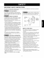 3
3
-
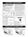 4
4
-
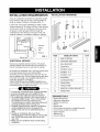 5
5
-
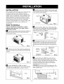 6
6
-
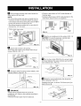 7
7
-
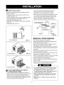 8
8
-
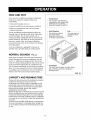 9
9
-
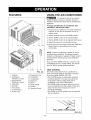 10
10
-
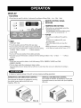 11
11
-
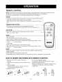 12
12
-
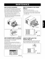 13
13
-
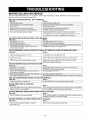 14
14
-
 15
15
-
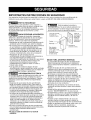 16
16
-
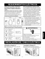 17
17
-
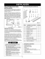 18
18
-
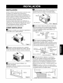 19
19
-
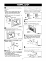 20
20
-
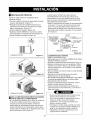 21
21
-
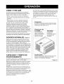 22
22
-
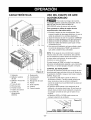 23
23
-
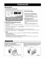 24
24
-
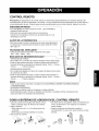 25
25
-
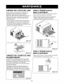 26
26
-
 27
27
-
 28
28
-
 29
29
-
 30
30
-
 31
31
-
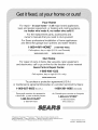 32
32


Kenmore 000 BTU Multi-Room Air Conditioner El manual del propietario
- Tipo
- El manual del propietario
- Este manual también es adecuado para
en otros idiomas
Artículos relacionados
-
Kenmore 75151 15,000 El manual del propietario
-
Kenmore 58075080500 Manual de usuario
-
-
-
-
-
-
-
-