Optimus A-035 Manual de usuario
- Categoría
- Equipo musical
- Tipo
- Manual de usuario

AMPLIFICADOR
AMPLIFIER
A-035
Manual de instalación y funcionamiento v1.0
Installation and operating instructions v1.0

A-035 Versión 1.0 Página 1 de 11
A
-035
Amplificador
INSTRUCCIONES DE SEGURIDAD:
IMPORTANTE:
Los códigos de color de los cables de red son los siguientes:
Si los colores de los cables de red de este aparato no se corresponden con las marcas de sus
terminales de conexión, debe procederse como sigue:
Conectar el cable de color verde y amarillo al terminal marcado con la letra E o con el símbolo de
tierra. Conectar el cable de color azul al terminal negro o marcado con la letra N. Conectar el cable
de color marrón al terminal rojo o marcado con la letra L.
INSTALACIÓN GENERAL
NO PASAR los cables de micrófono cerca de cables telefónicos, de datos o de línea de 100 V.
NO PASAR los cables de línea de 100 V cerca de cables telefónicos, de datos o de baja tensión.
NO SOBREPASAR el 90% de la potencia de salida de los amplificadores cuando se utiliza la línea
de 100 V para avisos.
NO SOBREPASAR el 70% de la potencia de salida de los amplificadores cuando se utiliza la línea
de 100 V para música ambiental a alto volumen.
NO UTILIZAR altavoces exponenciales para música ambiental, excepto si éstos han sido
especialmente diseñados para esta función.
EVITAR empalmes en los cables de micrófono. Si es inevitable, utilizar exclusivamente conectores
blindados de buena calidad, como los XLR.
Utilizar SIEMPRE para distancias largas, micrófonos balanceados de baja impedancia o aislados
de la masa conectados a entradas balanceadas.
Utilizar SIEMPRE un cable doble aislante de calidad equivalente a los de la red de baja tensión
para las conexiones de los altavoces.
ASEGURARSE de que todos los altavoces estén en fase.
ASEGURARSE de que no existe ningún cortocircuito en la línea de altavoces antes de conectarla
al amplificador.
Verde y amarillo Tierra (E)
Azul Neutro (N)
Marrón Positivo (L)

A-035 Versión 1.0 Página 2 de 11
A
-035
Amplificador
ÍNDICE
1.CARACTERÍSTICAS ................................................................................... 3
2.DESCRIPCIÓN ............................................................................................ 4
2.1. Panel frontal .......................................................................................................... 4
2.2. Panel posterior ...................................................................................................... 4
3.INSTALACIÓN ............................................................................................ 5
3.1. Precauciones......................................................................................................... 5
3.2. Conexión de entradas ........................................................................................... 5
3.3. Conexión de salidas de altavoces ......................................................................... 6
4.FUNCIONAMIENTO .................................................................................... 7
4.1. Control de ganancia de entrada ............................................................................ 7
4.2. Prioridad y TEL-PAGING ...................................................................................... 7
4.3. Alimentación Phantom .......................................................................................... 7
4.4. Music on Hold ........................................................................................................ 8
5.DIAGRAMA DE BLOQUES ......................................................................... 9
6.ESPECIFICACIONES TÉCNICAS ............................................................ 10
7.CERTIFICADO DE GARANTÍA ................................................................. 11

A-035 Versión 1.0 Página 3 de 11
A
-035
Amplificador
1. CARACTERÍSTICAS
Tres entradas de micro/línea con conectores XLR, RCA y Jack.
Amplio rango de nivel de entrada.
Entrada TEL-PAGING con conexión por regleta, con controles de volumen y activación.
Tres niveles de prioridad.
35 W de potencia RMS.
Alimentación phantom para el canal 1.
Protección por limitación de corriente y protección térmica.
Instalación en sobremesa o en rack de 19”.
Controles de tono de dos bandas, agudos y graves.
Bajo nivel de ruido y distorsión.
Perfecto para uso comercial e industrial.

A-035 Versión 1.0 Página 4 de 11
A
-035
Amplificador
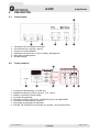
2. DESCRIPCIÓN
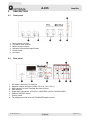
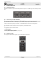
2.1. Panel frontal
2.2. Panel posterior
1. Conector de alimentación 110~240 Vca.
2. Salidas de altavoces (COM, 4-Ω, 8-Ω, 70 V, 100 V).
3. Salida y control de volumen MOH.
4. Controles de ganancia.
5. Entradas de audio. XLR (CH1), JACK/RCA (CH2 y CH3 MIC/LINE).
6. Interruptor de alimentación Phantom.
7. Interruptor de activación de prioridad.
8. Entrada TEL-PAGING con controles de volumen y nivel de activación.
1. Volúmenes de los canales de entrada.
2. Controles de tono, agudos y graves.
3. Control de volumen Master.
4. Indicadores de protección, nivel de salida y alimentación.
5. Interruptor de alimentación.
6. Entrada Auxiliar.

A-035 Versión 1.0 Página 5 de 11
A
-035
Amplificador
3. INSTALACIÓN
3.1. Precauciones
Antes de empezar, asegúrese que el amplificador está desconectado de la toma de corriente, con
el interruptor de alimentación en posición OFF y todos los controles de volumen al mínimo. En caso
de montaje en rack, no apile los equipos directamente, deje espacio suficiente entre equipos para
asegurar su correcta refrigeración.
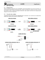
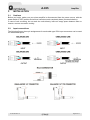
3.2. Conexión de entradas
La siguiente figura muestra los pines asignados para el cableado. Las conexiones de entrada RCA
pueden ser usadas para entradas no balanceadas.

A-035 Versión 1.0 Página 6 de 11
A
-035
Amplificador
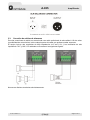
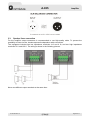
3.3. Conexión de salidas de altavoces
Para las conexiones de salida, se recomienda usar cable profesional de alta calidad. A fin de evitar
la posibilidad de cortocircuitos, aísle cualquier parte del cable que pudiese quedar expuesta.
El equipo incluye dos terminales de baja impedancia 4 Ω and 8 Ω, y tos terminales de alta
impedancia 70 V y 100 V. El cableado se muestra en las siguientes figuras.
Nunca use distintos terminales simultáneamente.

A-035 Versión 1.0 Página 7 de 11
A
-035
Amplificador
4. FUNCIONAMIENTO
4.1. Control de ganancia de entrada
Los canales del 1 al 3 disponen de un control de ganancia que permite ajustar su sensibilidad en un
rango de 44 dB.
4.2. Prioridad y TEL-PAGING
El equipo incluye prioridad por VOX para la entrada TEL-PAGING respecto a todos los canales, y
para la entrada del canal 1 respecto a los canales 2 y 3.
Al activarse la prioridad los canales con prioridad inferior serán silenciados.
Para activarse la prioridad en el canal 1 debe ajustarse el interruptor “TALKOVER” en posición ON.
El umbral de activación de la entrada TEL-PAGING puede ajustarse mediante el control
“TALKOVER”.
El equipo dispone de tres niveles de prioridad:
1 TEL-PAGING.
2 CH1 (con la prioridad activada)
2 CH1 (sin prioridad activada), CH2 y CH3.
4.3. Alimentación Phantom
El equipo dispone de alimentación Phantom +15 Vcc, seleccionable para el canal 1.

A-035 Versión 1.0 Página 8 de 11
A
-035
Amplificador
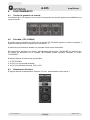
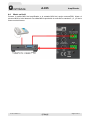
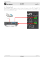
4.4. Music on Hold
Conecte la salida MOH del amplificador a la entrada MOH del equipo externo/PBX. Ajuste el
volumen MOH al nivel deseado. La salida MOH reproducirá el audio de los canales 2 y 3, y el de la
fuente musical interna.

A-035 Versión 1.0 Página 9 de 11
A
-035
Amplificador
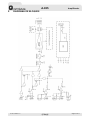
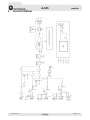
5. DIAGRAMA DE BLOQUES

A-035 Versión 1.0 Página 10 de 11
A
-035
Amplificador
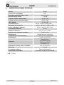
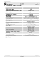
6. ESPECIFICACIONES TÉCNICAS
Modelo A-035
Potencia de salida (RMS)
35 W
Distorsión armónica (THD) a 1 kHz
Inferior a 0,5%
Relación Señal / Ruido
> 90 dB
Entradas de Micro balanceadas
-50 dB ±3 dB
Entradas de Línea no balanceadas
-30 dB ±3 dB
TEL-PAGING
-21 dB ±3 dB
Controles de tono
100 Hz, 10 kHz ±12 dB (±3 dB)
Respuesta en frecuencia
80 Hz ~ 18 kHz (+1.5 dB / -3 dB)
Ancho de banda de potencia
80 Hz ~ 18 kHz (< 0,5% THD)
Alimentación Phantom
15 Vcc
Salidas de altavoces
4 Ω, 8 Ω, 70 V y 100 V
Diafonía con volúmenes al máximo
-70 dB a 1 kHz
Refrigeración
Refrigeración por convección
Temperatura de funcionamiento
0 ~ 40 ºC con 95 % de humedad
Alimentación
110-240 Vca 50-60 Hz
Consumo
Máximo 60 W
1/3 potencia 26,8 W
1/8 potencia 15,8 W
Sin carga 7,7 W
Dimensiones (Ancho / Alto / Profundo)
270 x 76 x 230 mm
Peso neto
3,21 kg
Accesorios incluidos
Cable de alimentación
Accesorios no incluidos
Escuadras montaje en rack RM-3B
0 dB = 775 mV

A-035 Versión 1.0 Página 11 de 11
A
-035
Amplificador
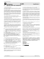
7. CERTIFICADO DE GARANTÍA
1. CERTIFICADO DE GARANTÍA
1. La empresa OPTIMUS S.A. garantiza que sus productos se encuentran
libres de defectos en materiales y de mano de obra en el momento de su
entrega original al comprador.
2. La empresa OPTIMUS S.A. concede a sus productos, conforme a las
condiciones aquí descritas, una garantía de dos (2) años a partir de la fecha de
adquisición del producto por el comprador. Si, dentro de este plazo de garantía,
se producen defectos que no sean debidos a razones mencionadas bajo el
punto 2, la empresa OPTIMUS S.A. remplazará o reparará el aparato utilizando
piezas de recambio equivalentes, nuevas o reconstruidas, según criterio propio.
Si se aplican piezas de recambio que constituyen una mejora del aparato, la
empresa OPTIMUS S.A. se reserva el derecho de cargar el coste adicional de
estos componentes al cliente.
3. No se concederán prestaciones de garantía distintas a las citadas.
4. Para la utilización de los derechos de garantía será requisito indispensable
presentar la factura de compra original o el certificado de garantía.
2. DISPOSICIONES DE GARANTÍA
1. Si el producto tuviera que ser modificado o adaptado para cumplir con los
requisitos locales en cuanto a técnica o seguridad, si no se trata del país para
el cual el producto fue concebido y fabricado originalmente, ello no se
considera como defecto de material o de fabricación. Por lo demás, la garantía
no comprende la realización de estas modificaciones o adaptaciones,
independientemente de si éstas hayan sido ejecutadas debidamente o no.
OPTIMUS S.A. tampoco asumirá costes en el marco de la garantía por este
tipo de modificaciones.
2. La garantía no dará derecho a inspección o mantenimiento gratuito o
reparación del aparato, particularmente si los defectos son debidos a uso
inapropiado. Los derechos de garantía tampoco abarcan defectos en piezas de
desgaste que sean debidos a un desgaste normal. Piezas de desgaste son, en
particular, potenciómetros, interruptores/teclas, y piezas similares.
3. La garantía no abarca los defectos en el equipo causados por:
Abuso o uso incorrecto del aparato para fines distintos a los previstos, en
incumplimiento de las instrucciones de servicio y de mantenimiento
especificadas en el Manual y/o Instrucciones Técnicas del equipo.
Conexión o uso del producto de una manera que no corresponda a los
requisitos técnicos o de seguridad del país en el cual se utiliza el
aparato.
Instalación en condiciones distintas a los indicados en el Manual y/o
Instrucciones Técnicas.
Deficiencia o interrupciones tensión eléctrica o defectos de instalación
que impliquen uso en condiciones anormales.
Daños ocasionados por otros equipos interconectados al producto.
El uso o instalación de Software (programas), interfaces, partes o
suministros no proporcionados y/o autorizados por OPTIMUS S.A.
La no utilización de los embalajes originales para su transporte.
Daños causados por fuerza mayor u otras causas no imputables a
OPTIMUS S.A.
4. No están cubiertos por esta garantía los siguientes elementos:
Todas las superficies de plástico y todas las piezas expuestas al exterior
que hayan sido rayadas o dañadas debido al uso normal o anormal.
Las roturas, golpes, daños por caídas o ralladuras causadas por
traslados de cualquier naturaleza.
Defectos de daños derivados de pruebas, uso, mantenimiento,
instalación y ajustes inapropiados, o derivados de cualquier alteración o
modificación de cualquier tipo no realizada por en Servicio Autorizado
por OPTIMUS S.A. en cumplimiento de esta garantía.
Los daños personales o a la propiedad que pudieran causar el uso
indebido del equipo, incluyendo la falta de mantenimiento.
5. La garantía carecerá de validez cuando se observe:
Enmiendas o tachaduras en los datos del certificado de garantía o
factura de compra.
Falta de factura original o falta de fecha en la misma.
Falta de número de serie o lote en el equipo.
6. La garantía no cubre los desplazamientos por asistencias técnicas a
excepción de los motivados por incidencias ocurridas durante los tres primeros
meses.
7. En el caso de ordenadores PC, la garantía no cubrirá la eliminación de virus
informáticos, restauración de programas por este motivo o la reinstalación del
disco provocada por el borrado del mismo.
8. Los derechos de garantía se anulan si el producto ha sido reparado o abierto
por un personal no autorizado OPTIMUS S.A. o por el propio cliente.
9. Si la empresa OPTIMUS S.A. estableciera al comprador del aparato que los
daños presentados no dan derecho a la reclamación de la garantía, los costes
de las prestaciones de revisión por parte de la empresa OPTIMUS S.A.
correrán a cargo del cliente.
10. Los productos sin derechos de garantía sólo se repararán contra pago de
los gastos por el cliente. En caso de ausencia de derechos de garantía,
OPTIMUS S.A. informará al cliente al respecto. Si, en un plazo de 6 semanas a
partir de esta comunicación, no recibimos ninguna orden de reparación escrita
confirmando la aceptación de los gastos, OPTIMUS S.A. devolverá el aparato
en cuestión al cliente. En este caso, los gastos de transporte y embalaje se
facturarán por separado y se cobrarán contra reembolso. En caso de
expedición de una orden de reparación, confirmando la asunción de los gastos,
los gastos de transporte y de embalaje se facturarán adicionalmente,
igualmente por separado.
11. En caso de necesidad de traslado al Centro de Servicio Autorizado, el
transporte será realizado por el responsable de la garantía, y serán a su cargo
los gastos de flete y seguro.
12. En caso de falla, OPTIMUS S.A. asegura al comprador la reparación y/o
reposición de partes para su correcto funcionamiento en un plazo no mayor a
30 días. No obstante, se deja aclarado que el plazo usual no supera los 30
días.
13. Todas las piezas o productos sustituidos al amparo de los servicios en
garantía pasarán a ser propiedad de OPTIMUS S.A.
3. TRANSFERENCIA DE LA GARANTÍA
La garantía se concede únicamente para el comprador original (cliente
principal) y es intransferible. Con excepción de la empresa OPTIMUS S.A.,
ningún tercero (comerciantes, etc.) está autorizado a conceder garantía
adicionales en nombre de la empresa OPTIMUS S.A.
4. RECLAMACIONES POR DAÑOS Y PERJUICIOS
En caso de que OPTIMUS S.A. no pueda proporcionar un servicio de garantía
adecuado, el comprador no tendrá ningún derecho a reclamar indemnización
alguna por daños y perjuicios consecuentes. La responsabilidad de la empresa
OPTIMUS S.A. se limita en todo caso al precio de facturación del producto
5. RELACIÓN CON OTROS DERECHOS DE GARANTÍA Y CON EL
DERECHO NACIONAL
1. Mediante esta garantía no se afecta a los derechos del comprador frente al
vendedor deducidos del contrato de compraventa concluido.
2. Las presentes condiciones de garantía de la empresa OPTIMUS S.A. son
válidas siempre que no contradigan el derecho nacional correspondiente en
relación con las disposiciones de garantía.
3. OPTIMUS S.A. asegura que este producto cumple con las normas de
seguridad vigentes en el país.
ESTA DECLARACIÓN DE GARANTÍA LIMITADA ES LA GARANTÍA
EXCLUSIVA OFRECIDA POR OPTIMUS S.A. SE EXCLUYE TODA OTRA
GARANTÍA EXPLÍCITA O IMPLÍCITA, INCLUIDAS LAS GARANTÍAS DE
COMERCIALIDAD Y APTITUD A UN FIN DETERMINADO. (EXCEPTO
CUANDO DICHAS GARANTÍAS SEAN REQUERIDAS POR UNA LEY
APLICABLE). NINGUNA GARANTÍA, YA SEA EXPLÍCITA O IMPLÍCITA, SE
APLICARÁ TRAS LA FINALIZACIÓN DEL PERIODO DE GARANTÍA.
OPTIMUS S.A.
Servicio Post Venta
C/ Barcelona 101
17003 - GIRONA
Tel. 902 151 96 / 972 203 300
Fax. 972 21 84 13
e-mail : [email protected]
1999/44/CE

A-035 Version 1.0 Page 1 of 11
A
-035
Am
p
lifier
SAFETY INSTRUCTIONS:
IMPORTANT:
The wires in the mains lead are coloured in accordance with the following code:
If the colours of the wires in the mains lead of this apparatus do not correspond with the colour
markings identifying the terminals in your plug, proceed as follows:
The wire which is coloured green and yellow must be connected to the terminal which is marked by
the letter E, or by the safety earth symbol or coloured green and yellow. The wire which is coloured
blue must be connected to the terminal which is marked with the letter N or coloured black. The wire
which is coloured brown must be connected to the terminal which is marked with the letter L or
coloured red.
GENERAL INSTALLATION
DO NOT run microphone cables near mains, data, telephone or 100V line cables.
DO NOT run 100V line cables near data, telephone or other low voltage cables.
DO NOT exceed 90% of the amplifier’s output power when using 100V line (speech only).
DO NOT exceed 70% of the amplifier’s output power when using 100V line (high level background
music).
DO NOT use horn loudspeakers for background music unless the loudspeaker has been specifically
designed for this purpose.
AVOID jointing the microphone cable, when this is unavoidable make sure a good screened
connector is used, e.g. XLR.
ALWAYS use a balanced or floating low impedance microphone terminating into a balanced input
on long microphone cable runs.
ALWAYS use a mains grade double insulated cable for the loudspeaker cable runs.
ENSURE that all loudspeakers are in-phase.
ENSURE that there are no short circuits on the loudspeaker line before connecting to the amplifier.
Green and Yellow Earth (E)
Blue Neutral (N)
Brown Live (L)

A-035 Version 1.0 Page 2 of 11
A
-035
Am
p
lifier
INDEX
1.SPECIFICATIONS ....................................................................................... 3
2.DESCRIPTION ............................................................................................ 4
2.1. Front panel ............................................................................................................ 4
2.2. Rear panel ............................................................................................................. 4
3.INSTALLATION ........................................................................................... 5
3.1. Cautions ................................................................................................................ 5
3.2. Input connections .................................................................................................. 5
3.3. Speaker lines connection ...................................................................................... 6
4.FUNCTIONALITY ........................................................................................ 7
4.1. Input gain control ................................................................................................... 7
4.2. CH1 Priority and TEL-PAGING ............................................................................. 7
4.3. Phantom power ..................................................................................................... 7
4.4. Music on Hold ........................................................................................................ 8
5.BLOCK DIAGRAM ...................................................................................... 9
6.TECHNICAL SPECIFICATIONS ............................................................... 10
7.GUARANTEE CERTIFICATE .................................................................... 11

A-035 Version 1.0 Page 3 of 11
A
-035
Am
p
lifier
1. SPECIFICATIONS
Three microphone/line inputs with JACK, XLR and RCA connectors.
Wide range input level.
TEL-PAGING input with EURO block terminal, with LEVEL & TALKOVER DEPTH controls.
Three layer priority.
35 W rated power output.
Phantom power for channel 1.
Advanced protection system includes current limiting, over current and thermal protection.
Desktop and 19-inches rack mountable type.
Two bands tone controls.
Low distortion and low noise level.
Ideal for commercial and industrial use.

A-035 Version 1.0 Page 4 of 11
A
-035
Am
p
lifier
2. DESCRIPTION
2.1. Front panel
2.2. Rear panel
1. AC mains connector 110~240 Vac.
2. Speaker outputs connector (COM, 4-Ω, 8-Ω, 70 V, 100 V).
3. MOH (Music On Hold) Terminal with level Control.
4. Gain controls.
5. Signal input connectors. XLR (CH1), JACK/RCA (CH2 & CH3 MIC/LINE).
6. Phantom ON/OFF switch.
7. Priority switch.
8. Tel-paging input with level and TALKOVER depth controls.
1. Input channel volumes.
2. Two bands tone controls.
3. Master volume control.
4. Indicators (Protection/output/Power).
5. Power switch.
6. Aux input.

A-035 Version 1.0 Page 5 of 11
A
-035
Am
p
lifier
3. INSTALLATION
3.1. Cautions
Before you begin, make sure your mixer-amplifier is disconnected from the power source, with the
power switch in OFF position and all level controls turned completely down (counterclockwise).
In case of rack mounting, do not stack the units directly; leave an empty space between them to
ensure a correct convection cooling.
3.2. Input connections
The following figures show pin assignments for each cable type. RCA input connectors can be used
for unbalanced inputs.

A-035 Version 1.0 Page 6 of 11
A
-035
Am
p
lifier
3.3. Speaker lines connection
For the amplifier output connectors is recommended to use high-quality cable. To prevent the
possibility of short-circuits, insulate exposed loudspeaker cable connectors.
The equipment includes two low impedance terminals 4 Ω and 8 Ω, and two high impedance
terminals 70 V and 100 V. The wiring is shown in the following pictures.
Never use different output terminals at the same time.

A-035 Version 1.0 Page 7 of 11
A
-035
Am
p
lifier
4. FUNCTIONALITY
4.1. Input gain control
Channels 1 to 3 have a gain control which permits to adjust, in a 44 dB range, the sensitivity of each
one.
4.2. CH1 Priority and TEL-PAGING
This equipment includes VOX priority for TEL-PAGING input over all channels and for channel 1
input over channels 2 and 3. When priority is activated, lower priority channels are muted.
In order to activate the priority of channel 1, TALKOVER switch must be set to ON position.
TEL-PAGING activation threshold can be adjusted by TALKOVER control.
This equipment has two priority layers:
1 TEL-PAGING.
2 CH1 (With priority activated)
2 CH1 (Without priority activated), CH2 y CH3.
4.3. Phantom power
This equipment has Phantom power +15 Vdc selectable for Channel 1.

A-035 Version 1.0 Page 8 of 11
A
-035
Am
p
lifier
4.4. Music on Hold
Connect amplifier’s MOH output to music-on-hold input of telephone interface/PBX. Set MUSIC ON
HOLD volume to proper level. Audio of Channels 2 and 3 as well as audio of internal BGM source
will be broadcasted by MOH output.

A-035 Version 1.0 Page 9 of 11
A
-035
Am
p
lifier
5. BLOCK DIAGRAM

A-035 Version 1.0 Page 10 of 11
A
-035
Am
p
lifier
6. TECHNICAL SPECIFICATIONS
Model A-035
Output power (RMS)
35 W
Total Harmonic Distortion(THD) at 1 kHz
Less than 0.5%
Signal to noise ratio
> 90 dB
Balanced Mic Inputs
-50 dB ±3 dB
Unbalanced AUX Channels
-30 dB ±3 dB
TEL-PAGING
-21 dB ±3 dB
Tone controls
100 Hz & 10 kHz ±12 dB (±3 dB)
Frequency Response
80 Hz ~ 18 kHz (+1.5 dB / -3 dB)
Power Band Width
80 Hz ~ 18 kHz (less than 0.5% THD)
Phantom Power
15 Vdc
Speaker Outputs
4 Ω, 8 Ω, 70 V & 100 V
Crosstalk at all control maximum
-70 dB at 1 kHz
Cooling
Convection cooled
Operating temperature
0 ~ 40 ºC at 95% humidity
Input Power
110-240 Vac 50-60 Hz
Power consumption
Maximum 60 W
1/3 power 26.8 W
1/8 power 15.8 W
Unloaded 7.7 W
Dimensions (width / Height / Depth)
270 x 76 x 230 mm
Net Weight
3.21 kg
Accessories included
AC power cable
Accessories not included
RM-3B rack mounting brackets
0 dB = 775 mV

A-035 Version 1.0 Page 11 of 11
A
-035
Am
p
lifier
7. GUARANTEE CERTIFICATE
1. GUARANTEE CERTIFICATE
1. OPTIMUS S.A. guarantees that its products are free from material and
manufacturing defects when they are first delivered to the purchaser.
2. In accordance with the conditions outlined here, OPTIMUS S.A. guarantees its
products for two (2) years from the date on which the purchaser acquires the
product. If, within this guarantee period, defects appear which are not due to
factors outlined in section 2, OPTIMUS S.A. shall replace or repair the unit using
equivalent, new or reconstructed replacement parts, as it deems fit. If
replacement parts are applied which improve the unit, OPTIMUS S.A. reserves
the right to charge the client for the additional cost of these components.
3. No guarantee benefits shall be provided other than those cited here.
4. In order to claim the guarantee rights, it shall be an essential requirement to
present the original purchase invoice or the guarantee certificate.
2. GUARANTEE PROVISIONS
1. In the event that the product had to be modified or adapted to comply with local
requirements concerning technical specifications or safety, and if the country in
question is not the country for which the product was originally designed and
manufactured, defects are not considered to be material or manufacturing
defects. Furthermore, the guarantee does not cover the execution of these
modifications or adaptations, regardless of whether or not they have been carried
out correctly.
Nor shall OPTIMUS S.A. be responsible for any costs under this guarantee for
these types of modifications.
2. The guarantee shall not entitle the purchaser to inspection or free maintenance
or repair of the unit, particularly if the defects are due to inappropriate use. Nor do
the guarantee rights cover defects in wearing parts that become worn as a result
of normal wear and tear. Wearing parts are, in particular, potentiometers,
switches/keys, and similar parts.
3. The guarantee does not cover defects in the equipment unit caused by:
Abuse or incorrect use of the unit for purposes other than those for which it
is intended, in non-compliance with the service and maintenance
instructions specified in the Manual and/or Technical Instructions for the
unit.
Connection or use of the product in a manner that does not correspond to
the technical or safety requirements of the country in which the unit is used.
Installation in conditions other than those indicated in the Manual and/or
Technical Instructions.
Deficiency or interruptions in the electricity supply or installation defects
which imply use in abnormal conditions.
Damage caused by other equipment units that are connected to the
product.
The use or installation of Software (programmes), interfaces, parts or
supplies not provided and/or not authorised by OPTIMUS S.A.
Failure to use the original packaging for transportation.
Damage caused by force majeure or other causes not attributable to
OPTIMUS S.A.
4. The following elements are not covered by this guarantee:
All plastic surfaces and all parts exposed to outdoor conditions which have
been scratched or damaged as a result of normal or abnormal use.
Breakages, knocks, damage due to a fall or scratches caused by moving
the unit in any way.
Damage caused by tests, use, maintenance, installation or inappropriate
adjustments, or as a result of any alteration or modification of any kind not
carried out by a Service Authorised by OPTIMUS S.A. in compliance with
this guarantee.
Damage to persons or property that might be caused by the improper use
of the equipment, including lack of maintenance.
5. The guarantee shall not be valid whenever the following is observed:
Amendments or corrections made to the details of the guarantee certificate
or purchase invoice.
Failure to produce the original invoice or the absence of a date on this.
Absence of the serial or batch number on the equipment.
6. The warranty does not cover travel for technical assistance except for those
caused by incidents occurred during the first three months.
7. In the case of personal computers, the guarantee will not cover the
elimination of computer viruses, the restoration of programmes damaged by
these or the reinstallation of the disk following its deletion.
8. The rights of this guarantee are invalidated if the product has been
repaired or opened by staff unauthorised by OPTIMUS S.A. or by the client
himself.
9. If OPTIMUS S.A. were to establish before the purchaser that the damage
affecting the unit does not entitle a claim to be made under the guarantee,
the costs of checking the equipment incurred by OPTIMUS S.A. shall be
borne by the client.
10. Products not covered by the guarantee shall only be repaired once
payment has been effected by the client. In the event that the guarantee
rights do not apply, OPTIMUS S.A. shall duly inform the client. If, within a
period of 6 weeks from this communication, no written repair order is
received from the client confirming acceptance of the costs, OPTIMUS S.A.
shall return the unit in question to the client. In this case, the transport and
packaging costs shall be invoiced separately and payment shall be made on
delivery. In the event that a repair order is sent by the client, confirming that
he assumes the costs of repair, the transport and packaging costs shall be
invoiced additionally, and also separately.
11. If the equipment needs to be transferred to the Authorised Service
Centre, transportation shall be effected by the responsible party according
to the guarantee, who will also bear the freight and insurance costs.
12. In the event of a defect, OPTIMUS S.A. guarantees that the repair
and/or replacement of parts so that the unit operates correctly will be made
within a period of no more than 30 days. Nevertheless, OPTIMUS S.A.
would like to clarify that the normal period does not exceed 30 days.
13. All parts or products replaced as part of the guarantee services shall
become the property of OPTIMUS S.A.
3. TRANSFER OF GUARANTEE
The guarantee is solely awarded to the original purchaser (principal client)
and is not transferable. With the exception of OPTIMUS S.A., no third party
(dealers, etc.) is authorised to award additional guarantees on behalf of
OPTIMUS S.A.
4. CLAIMS FOR DAMAGE
In the event that OPTIMUS S.A. cannot provide a suitable guarantee
service, the purchaser shall not be entitled to claim any indemnity for
damages arising. The responsibility held by OPTIMUS S.A. is limited in all
cases to the invoicing price of the product.
5. RELATION WITH OTHER GUARANTEE RIGHTS AND NATIONAL
LAW
1. This guarantee does not affect the rights of the purchaser with respect to
the vendor arising from the contract of sale accomplished.
2. These conditions of the guarantee provided by OPTIMUS S.A. are valid
as long as they do not contradict the corresponding national law on
guarantee provisions.
3. OPTIMUS S.A. guarantees that this product complies with the safety
regulations in force in the country.
THIS LIMITED GUARANTEE DECLARATION IS THE EXCLUSIVE
GUARANTEE OFFERED BY OPTIMUS S.A. ALL OTHER EXPLICIT OR
IMPLICIT GUARANTEES ARE EXCLUDED, AND THIS ALSO APPLIES TO
GUARANTEES OF MARKETABILITY AND SUITABILITY FOR A
PARTICULAR PURPOSE. (EXCEPT WHEN THESE GUARANTEES ARE
REQUIRED BY AN APPLICABLE LAW). NO GUARANTEE, EITHER
EXPLICIT OR IMPLICIT, SHALL BE APPLIED ONCE THE GUARANTEE
PERIOD HAS EXPIRED.
OPTIMUS S.A.
After-Sales Service
C/ Barcelona 101
17003 - GIRONA
Tel.: 902 151 96 / 972 203 300
Fax: 972 21 84 13
e-mail : [email protected]
1999/44/CE
-
 1
1
-
 2
2
-
 3
3
-
 4
4
-
 5
5
-
 6
6
-
 7
7
-
 8
8
-
 9
9
-
 10
10
-
 11
11
-
 12
12
-
 13
13
-
 14
14
-
 15
15
-
 16
16
-
 17
17
-
 18
18
-
 19
19
-
 20
20
-
 21
21
-
 22
22
-
 23
23


Optimus A-035 Manual de usuario
- Categoría
- Equipo musical
- Tipo
- Manual de usuario
en otros idiomas
- English: Optimus A-035 User manual
Artículos relacionados
-
Optimus A-065M Manual de usuario
-
-
-
-
-
-
-
-
-
Optimus A-8240X Manual de usuario