
SERIE A8000X
A8000X SERIES
Manual de instalación y funcionamiento v1.4
Installation and operating instructions v1.4

Serie A8000X Versión 1.4 Página 1 de 33
Serie A8000X
INSTRUCCIONES DE SEGURIDAD:
IMPORTANTE:
Los códigos de color de los cables de red son los siguientes:
Si los colores de los cables de red de este aparato no se corresponden con las marcas de sus
terminales de conexión, debe procederse como sigue:
Conectar el cable de color verde y amarillo al terminal marcado con la letra E o con el símbolo de
tierra. Conectar el cable de color azul al terminal negro o marcado con la letra N. Conectar el cable
de color marrón al terminal rojo o marcado con la letra L.
¾ Lea atentamente las instrucciones de seguridad.
¾ Guarde este manual para futuras consultas.
¾ Asegúrese de que el voltaje de la red es el mismo que el del aparato. De lo contrario el
aparato puede resultar dañado. Desenchufe el equipo durante las tormentas eléctricas y
cuando no se vaya a usar durante un largo período de tiempo.
¾ Use siempre cables ya preparados para evitar riesgos de descargas eléctricas o fuego. En
caso de tener dudas, consulte con un instalador cualificado.
¾ No quite ningún panel, dentro del equipo existen zonas con un alto voltaje. Los paneles sólo
pueden ser desmontados por personal cualificado.
¾ Para evitar riesgo de fuego y cualquier otro daño en el equipo, use sólo fusibles equivalentes
al original. No cortocircuite el soporte del fusible. Desconecte la alimentación antes de
cambiarlo.
¾ Antes de encender el aparato, asegúrese de que la toma de tierra está conectada.
¾ No use el aparato en lugares húmedos o cerca de líquidos. No instale el aparato cerca de
fuentes de calor. No bloquee los orificios de ventilación.
¾ Cuando sea necesario, retire el polvo con un paño seco. No use disolventes como el alcohol.
Mantenga el aparato limpio y sin polvo.
¾ Se requiere personal cualificado para realizar todas las operaciones de mantenimiento.
Nota: La información proporcionada por este manual no incluye detalles de diseño,
producción o variaciones en el equipo. Tampoco incluye posibles situaciones de riesgo
durante la instalación, funcionamiento o mantenimiento. Si usted necesita asistencia
especial más allá del manual, por favor contacte con nuestro servicio técnico.
Verde y amarillo Tierra (E)
Azul Neutro (N)
Marrón Positivo (L)

Serie A8000X Versión 1.4 Página 2 de 33
Serie A8000X
ÍNDICE
1. EQUIPOS DEL SISTEMA ............................................................................................ 4
1.1 A-8240X ............................................................................................................. 4
1.2 CD-7................................................................................................................... 4
1.3 AWP-06 .............................................................................................................. 4
1.4 APS-06 ............................................................................................................... 4
1.5 APS-EX .............................................................................................................. 5
1.6 AEX-8000 ........................................................................................................... 5
2. PANEL FRONTAL A-8240X......................................................................................... 6
3. PANEL POSTERIOR A-8240X .................................................................................... 7
4. PANEL FRONTAL CD-7 .............................................................................................. 8
5. PANEL FRONTAL AWP-06 ......................................................................................... 9
6. PANEL FRONTAL APS-06 ........................................................................................ 10
7. PANEL POSTERIOR APS-06.................................................................................... 10
8. APS-EX...................................................................................................................... 11
9. PANEL FRONTAL AEX-8000 .................................................................................... 11
10. PANEL POSTERIOR AEX-8000................................................................................ 12
11. INSTALACIÓN Y FUNCIONAMIENTO ...................................................................... 13
11.1 Seleccionar tensión de alimentación CA .......................................................... 13
11.2 Conectar cable de alimentación CA ................................................................. 13
11.3 Seleccionar modo de funcionamiento............................................................... 13
11.4 Seleccionar monitorización 20 kHz................................................................... 13
11.5 Seleccionar nivel de prioridad MIC 1 ~ 6.......................................................... 13
11.6 Seleccionar el tipo de Gong ............................................................................. 14
11.7 Conexión de los micrófonos ............................................................................. 14
11.8 Conexión entradas BGM .................................................................................. 15
11.9 Entrada TEL EMER.......................................................................................... 15
11.10 Entrada TEL EMER 100 V................................................................................ 15
11.11 MOH música en espera.................................................................................... 16
11.12 Conexión APS-06............................................................................................. 16
11.13 Configuración APS-06 ...................................................................................... 16
11.14 Panel remoto AWP-06...................................................................................... 18
11.15 APS-EX conexión y montaje ............................................................................ 19
11.16 External Amplifier OUT..................................................................................... 19
11.17 REC out / Power in / PRE out........................................................................... 19
11.18 Salidas de 100 V .............................................................................................. 20
11.19 0 / 8 / 70 V / 100 V ........................................................................................ 20
11.20 Encendido remoto ............................................................................................ 21
11.21 Conexión de alimentación por baterías ............................................................ 21
11.22 Conexión AEX-8000......................................................................................... 22
12. EJEMPLOS DE INSTALACIÓN ................................................................................. 23
12.1 Sistema de 1 canal 6 zonas 240 W .................................................................. 23
12.2 Sistema de 1 canal 18 zonas 240 W ................................................................ 23
12.3 Sistema de 1 canal 18 zonas hasta 360 W ...................................................... 24
12.4 Sistema de 2 canales 18 zonas 360 W ............................................................ 25

Serie A8000X Versión 1.4 Página 3 de 33
Serie A8000X
13. FUNCIONAMIENTO CD-7 ......................................................................................... 26
13.1 Modo CD / USB / SD........................................................................................ 26
13.2 Modo Radio ...................................................................................................... 27
13.3 Memoria ........................................................................................................... 28
14. ESPECIFICACIONES TÉCNICAS A-8240X .............................................................. 29
15. ESPECIFICACIONES TÉCNICAS AWP-06............................................................... 30
16. ESPECIFICACIONES TÉCNICAS APS-06................................................................ 31
17. APS-EX TECHNICAL SPECIFICATIONS.................................................................. 31
18. ESPECIFICACIONES TÉCNICAS AEX8000............................................................. 32
19. CERTIFICADO DE GARANTÍA.................................................................................. 33

Serie A8000X Versión 1.4 Página 4 de 33
Serie A8000X
1. EQUIPOS DEL SISTEMA
1.1 A-8240X
• Amplificador mezclador de seis zonas con seis entradas de micrófono.
• Cada entrada dispone de un potenciómetro para ajustar el nivel de la señal.
• Cada entrada dispone de un potenciómetro de ajuste para altas y bajas frecuencias.
• Las entradas 5 y 6 disponen de un conmutador para selección de nivel MIC / LINEA.
• La entrada BGM dispone de un selector para Remote, Source, Aux 1, Aux 2 y Aux 3.
• El equipo cuenta con un regulador de volumen general que puede controlar la salida de
todas las zonas.
• La entrada de Micro 1 tiene un conector tipo RJ45 utilizado para realizar una llamada
general.
• El orden de prioridades es el siguiente: Tel / Emerg > Paging Station > Micrófonos > BGM.
• Las entradas 1, 2, 3 y 4 disponen de cuatro niveles distintos de prioridad.
1.2 CD-7
• Fuente musical multiformato.
• Entrada para CD, dispositivo USB y tarjeta de memoria SD.
• Soporte para formatos MP3 y WMA.
• Funciones de repetición, reproducción aleatoria y programación de canciones.
• Función radio AM FM.
• 10 memorias para sintonías de radio.
1.3 AWP-06
• Panel remoto de control para montaje en pared.
• Puede controlar la zona y la fuente BGM del A-8240X.
• El control remoto de volumen permite ajustar el nivel de señal de salida del A-8240X.
• Conectores de entrada MIC / LINE para fuentes de audio externas.
• La señales de MIC / LINE se pueden mezclar mediante el regulador Mix Level.
1.4 APS-06
• Micrófono de control con 6 zonas.
• Todos los ajustes se pueden realizar y memorizar con las teclas.
• Incorpora un cuello de cisne flexible y un micrófono de condensador unidireccional.
• Botones Lock y PTT, para modo enclavamiento o pulsar para hablar.
• Salida balanceada con nivel de línea para enviar el audio a larga distancia.
• Cada APS-06 dispone de dos conectores RJ45.
• Se pueden conectar hasta 6 micros APS-06 para ampliar el sistema.
• Configuración mediante las teclas: ID, sensibilidad, prioridad, gong y filtro de voz.
• Cada unidad cuenta con 6 teclas de zona. Cuando se selecciona una zona, su indicador
LED correspondiente se ilumina.
• Tecla "All" para realizar una llamada a todas las zonas, al mismo tiempo.

Serie A8000X Versión 1.4 Página 5 de 33
Serie A8000X
1.5 APS-EX
• Expansión de 12 teclas para APS-06.
• LED indicador de estado para cada zona.
• Pueden instalarse 4 unidades por cada APS-06.
1.6 AEX-8000
• El AEX-8000 se utiliza como equipo de expansión de zonas.
• Las zonas expandidas pueden ser controladas desde el micrófono o manualmente
pulsando el interruptor del frontal.
• Cada unidad tiene 12 selectores de zona. Cuando se seleccione una zona determinada, su
LED indicador correspondiente se iluminará.
• Dispone de dos terminales RJ45 para comunicarse con la A-8240X.
• Tres modos de funcionamiento disponibles. Expandir las zonas de A-8240X, expandir las
zonas y la potencia del A8240X añadiendo un amplificador externo y expandir las zonas y
la potencia con doble canal utilizando dos amplificadores.

Serie A8000X Versión 1.4 Página 6 de 33
Serie A8000X
2. PANEL FRONTAL A-8240X
(1) Controles de volumen de MIC 1~4.
(2) Controles de tono agudos/graves para
MIC1~4.
(3) Controles de volumen de MIC5/LINE1 y
MIC6/LINE2.
(4) Controles de tono agudos/graves para
MIC5/LINE1 y MIC6/LINE2.
(5) Control de volumen para remoto/fuente
musical/auxiliar 1~3.
(6) Controles de tono agudos/graves para
remoto/fuente musical/auxiliar 1~3.
(7) Selector de dispositivo BGM:
remoto/fuente musical/auxiliar 1~3.
(8) Controlador de volumen general.
(9) Indicador LED de encendido.
(10) Indicador LED de fallo.
(11) Interruptor de llamada general.
(12) Indicador de nivel.
(13) Selectores y indicadores LED
independientes para las zonas 1~6.
(14) Controles de volumen independientes
para las zonas 1~6. Regulación de 5 pasos.
(15) Ranura para la fuente musical opcional
(CD-7).

Serie A8000X Versión 1.4 Página 7 de 33
Serie A8000X
3. PANEL POSTERIOR A-8240X
(16) Interruptor de encendido.
(17) Entrada de alimentación de corriente
alterna.
(18) Fusible de protección.
(19) Terminal de entrada 24 Vcc.
(20) Terminales de salida de potencia.
(21) Terminal de encendido remoto.
(22) Interruptor de selección de modo.
(23) Interruptor de supervisión 20 kHz.
(24) Interruptor selector de prioridad para
MIC1~6.
(25) Interruptor selector del tono de aviso.
(26) Regulador de volumen del gong.
(27) Conector RCA de entrada AUX 2 y 3.
(28) Conector XLR de entrada AUX 1.
(29) Interruptor selector de MIC6/Phantom/
LINE2.
(30) Conector XLR de entrada MIC6/LINE2.
(31) Interruptor selector de MIC5/Phantom/
LINE1.
(32) Conector XLR de entrada MIC5/LINE1.
(33) Conector XLR de entrada MIC4.
(34) Interruptor Phantom ON/OFF MIC3/4.
(35) Conector XLR de entrada MIC3.
(36) Conector XLR de entrada MIC2.
(37) Interruptor Phantom ON/OFF MIC1/2.
(38) Interruptor de PTT (Push to Talk).
(39) Conector XLR de entrada MIC1.
(40) Conector RJ45 de entrada MIC1.
(41) Regulador de nivel de MOH.
(42) Terminal de salida de 8 MOH.
(43) Terminal de salida balanceada MOH.
(44) Terminal de entrada AM/FM (Opcional).
(45) Terminal de entrada TEL/EMER 100V.
(46) Terminal de entrada TEL/EMER 1V.
(47) Regulador de nivel de TEL/EMER.
(48) Conector RJ45 de entrada micro APS-06
con prioridad.
(49) Conector RJ45 para panel AWP-06.
(50) Conector XLR de salida para
Amplificador externo.
(51) Conector RCA de salida para grabación.
(52) Conector RCA de entrada de Previo.
(53) Conector RCA de salida de Previo.
(54) Regulador de nivel del MUTE.
(55) Conector RJ45 para AEX-8000.
(56) Terminal de entrada de amplificador
externo.
(57) Terminales de salida de zonas 1~6.
(58) Selector de voltaje AC de entrada.

Serie A8000X Versión 1.4 Página 8 de 33
Serie A8000X
4. PANEL FRONTAL CD-7
(1) Conector de entrada USB.
(2) Receptor IR.
(3) Ranura para tarjeta SD.
(4) Selector de fuente CD / USB / SD / TUN.
(5) Selector de cambio de programa/banda de radio.
(6) Botón Mute / incremento sintonía de radio.
(7) Botón de reproducción / pausa o decrementa la sintonía de radio.
(8) Botón de parada o expulsión de CD.
(9) Botón de encendido.
(10) Botón de avance rápido.
(11) Botón de retroceso rápido.
(12) Botón de siguiente canción.
(13) Botón de canción anterior.
(14) Botón de activación de reproducción aleatoria.
(15) Botón de repetición.
(16) Ranura para CD.
(17) Pantalla LCD.

Serie A8000X Versión 1.4 Página 9 de 33
Serie A8000X
5. PANEL FRONTAL AWP-06
(1) Interruptores y LEDs selectores
de zonas y llamada general.
(2) Selector de fuente de sonido /
AUX 1~3.
(3) Entrada de micrófono.
(4) Entrada de línea.
(5) Controlador del nivel de mezcla.
(6) Pulsador de encendido.
(7) Regulador de volumen general.
(8) Conector de datos (Panel posterior).

Serie A8000X Versión 1.4 Página 10 de 33
Serie A8000X
6. PANEL FRONTAL APS-06
(1) Conector para micrófono.
(2) Botones de zona.
(3) Botón de llamada general.
(4) Indicadores LED de Talk / Busy.
(5) Botón de hablar con enclavamiento.
(6) Botón de pulsar para hablar PTT.
7. PANEL POSTERIOR APS-06
(7) Regulador de nivel del audio de salida.
(8) Conector RJ45 de salida de audio.
(9) Conector RJ45 de entrada de audio.
(10) Entrada de alimentación de 24 Vcc.

Serie A8000X Versión 1.4 Página 11 de 33
Serie 8000
8. APS-EX
(1) Pulsadores de zona.
(2) Indicadores LED de zona.
(3) Conector de entrada
(4) Conector de salida.
9. PANEL FRONTAL AEX-8000
(1) Pulsadores de selección de zona.
(2) Indicadores LED de zona.
(3) Pulsador de dispositivo auxiliar. (Sin uso)
(4) Indicador LED de auxiliar. (Sin uso)
(5) Indicadores LED de fallo Amp1 / Amp2.
(Sin uso)
(6) Indicador LED de encendido.

Serie A8000X Versión 1.4 Página 12 de 33
Serie 8000
10. PANEL POSTERIOR AEX-8000
(7) Entrada de alimentación de corriente
alterna.
(8) Fusible de protección.
(9) Interruptor de encendido.
(10) Toma de tierra.
(11) Selector de voltaje AC de entrada.
(12) Terminal de encendido remoto.
(13) Terminal de entrada 24Vcc.
(14) Interruptor identificador de dirección.
(15) Terminal RJ-45 de salida.
(16) Terminal RJ-45 de entrada.
(17) Regulador de nivel auxiliar.
(18) Conector RCA de entrada auxiliar.
(19) Conector XLR hacia amplificador 2.
(20) Conector XLR hacia amplificador 1.
(21) Terminal de entrada del amplificador 2.
(22) Terminal de entrada del amplificador 1.
(23) Terminales de salida de Z1 a Z12.

Serie A8000X Versión 1.4 Página 13 de 33
Serie A8000X
11. INSTALACIÓN Y FUNCIONAMIENTO
11.1 Seleccionar tensión de alimentación CA
Nunca utilice una tensión distinta a la de la red, hacerlo podría dañar el equipo.
11.2 Conectar cable de alimentación CA
11.3 Seleccionar modo de funcionamiento
Ajuste el conmutador de selección de modo a la posición OFF
(arriba) para utilizar el equipo en modo “Stand Alone”.
Ajuste el conmutador de selección de modo a la posición ON
(abajo) para utilizar el equipo en modo “Dual Channel”.
11.4 Seleccionar monitorización 20 kHz
Ajuste el conmutador de monitorización 20 kHz a la posición
OFF (arriba). Frecuencia 20 kHz deshabilitada.
11.5 Seleccionar nivel de prioridad MIC 1 ~ 6
Seleccione la prioridad de las entradas de micrófono 1~ 6 según la tabla siguiente:
Nota: En modo MIX los micrófonos se mezclan con la música.
PRIORIDAD 3 4
CASCADA MIC1 > MIC2 > MIC3 > MIC4
> MIC5 > MIC6
OFF 0FF
FIFO Primero en entrar máxima prioridad OFF 0N
LIFO Último en entrar máxima prioridad 0N 0FF
MIX Las entradas se mezclan 0N ON

Serie A8000X Versión 1.4 Página 14 de 33
Serie A8000X
11.6 Seleccionar el tipo de Gong
Existen 4 configuraciones distintas seleccionables en función de la tabla siguiente:
GONG 5 6
GONG OFF
OFF OFF
GONG 1
OFF ON
GONG 2
ON OFF
GONG 3
ON ON
El gong es activado desde el conector RJ45 del conector MIC1. El Gong del APS-06 está incluido
en la propia unidad y no es afectado por esta configuración.
11.7 Conexión de los micrófonos
El equipo dispone de dos tipos de conector para la entrada MIC1, XLR/JACK y RJ45.
La entrada MIC1 puede atenuar, según configuración, el resto de entradas excepto la TEL EMER.
Dispone de dos opciones de funcionamiento, “mute” por contacto o por VOX.
Ajuste PTT a ON para activar la función “mute” por contacto, o PTT a OFF para activar la función
“mute” por VOX.
Al utilizar la función “mute” por contacto MIC1 cortará los otros micros y se activarán todas las
zonas. En el caso de “mute por VOX deberán seleccionarse manualmente.
Active la alimentación Phantom para la entradas M1 ~ 6 si los micrófonos conectados requieren
este tipo de alimentación.
Seleccione el nivel de entrada para las entradas MIC5/LINE1 y MIC6/LINE2. El nivel de línea es
de 200 mV.

Serie A8000X Versión 1.4 Página 15 de 33
Serie A8000X
11.8 Conexión entradas BGM
El equipo dispone de dos tipos de entrada para fuentes musicales, XLR/JACK para AUX1 y RCA
para AUX2 y AUX3. Ambos conectores no son balanceados.
También puede disponer, opcionalmente, de una fuente musical integrada (CD-7) con CD-MP3
USB/SD y radio. La fuente música utilizada puede seleccionarse desde los botones frontales o
desde el panel remoto opcional AWP-06.
11.9 Entrada TEL EMER
Entrada balanceada para señales de nivel AUX. Esta entrada dispone de prioridad por “VOX” que
activa todas las zonas y corta el resto de entradas. Conecte la entrada utilizando los terminales 0,
100V. Puede regularse el volumen desde el potenciómetro TEL Level.
11.10 Entrada TEL EMER 100 V
Entrada balanceada para señales de nivel 100 V. Esta entrada dispone de prioridad por “VOX”
que corta el resto de entradas y activa todas las zonas. Conecte la entrada utilizando los
terminales 0 y 100V. Puede regularse el volumen desde el potenciómetro TEL Level.

Serie A8000X Versión 1.4 Página 16 de 33
Serie A8000X
11.11 MOH música en espera
El equipo dispone de dos tipos de conectores para la música en espera, uno a nivel de auxiliar (0
dB) y otro de baja impedancia 8 (1 W) para conectar directamente un altavoz. El volumen es
controlado mediante el potenciómetro MOH Level.
11.12 Conexión APS-06
Pueden conectarse hasta 6 pupitres APS-6 al A-8240X.
Use cable CAT 5. Conecte un cable con conectores RJ45 entre la unidad principal y los pupitres.
La distancia máxima del bus es de 600 m. Para distancias de más de 100 metros es necesario
alimentar los pupitres externamente.
El pupitre APS-06 no es afectado por los volúmenes de zonas ni por el volumen master.
11.13 Configuración APS-06
ID de la unidad:
Debe asignarse una ID para cada estación de llamada APS-06. Pulse las teclas TALK y Z6
simultáneamente durante 3 segundos. Los LEDs TALK y Z6 parpadearán. Pulse la tecla Z6 y el
estado de los LED cambiará secuencialmente. La ID corresponderá al número de la tabla
siguiente. (LED ON = 1, LED OFF = 0).
Pulse la tecla TALK para salir de la configuración.

Serie A8000X Versión 1.4 Página 17 de 33
Serie A8000X
ID Z4 Z3 Z2 Z1
1
0 0 0 1
2
0 0 1 0
3
0 0 1 1
4
0 1 0 0
5
0 1 0 1
6
0 1 1 0
7
0 1 1 1
8
1 0 0 0
Sensibilidad del micrófono:
Pulse las teclas TALK y Z5 simultáneamente durante 3 segundos. Los LEDs TALK y Z5 se
encenderán. Pulse la tecla Z5 y el estado de los LEDs cambiará secuencialmente
incrementándose la ganancia en cada salto. (LED ON = 1, LED OFF = 0).
Pulse la tecla TALK para salir de la configuración.
SENSIBILIDAD Z3 Z2 Z1
MIN
0 0 1
0 1 0
0 1 1
1 0 0
1 0 1
MAX
1 1 0
Prioridad:
Los ajustes de prioridad solo se definen en la primera unidad. Pulse las teclas TALK y Z4
simultáneamente durante 3 segundos. Los LEDs TALK y Z4 se encenderán. Pulse la tecla Z4 y el
estado de los LEDs cambiará secuencialmente modificándose el tipo de prioridad. (LED ON = 1,
LED OFF = 0).
Pulse la tecla TALK para salir de la configuración.
PRIORIDAD Z3 Z2 Z1
CASCADA 1>2>3>4>5>6
0 0 1
FIFO
0 1 0
LIFO
0 1 1
MIX
1 0 0
Gong:
Los ajustes de gong solo se definen en la primera unidad. Pulse las teclas TALK y Z3
simultáneamente durante 3 segundos. Los LEDs TALK y Z3 se encenderán. Pulse la tecla Z3 y el
estado de los LEDs cambiará secuencialmente modificándose el tipo de gong. (LED ON = 1, LED
OFF = 0).
Pulse la tecla TALK para salir de la configuración.
GONG Z2 Z1
OFF
0 0
GONG 1
0 1
GONG 2
1 0
GONG 3
1 1

Serie A8000X Versión 1.4 Página 18 de 33
Serie A8000X
Filtro de palabra:
Pulse las teclas TALK y Z2 simultáneamente durante 3 segundos. Los LEDs TALK y Z3 se
encenderán. Pulse la tecla Z3 y el estado de los LEDs cambiará secuencialmente activándose y
desactivándose el filtro de palabra. (LED ON = 1, LED OFF = 0).
Pulse la tecla TALK para salir de la configuración.
FILTRO Z1
ON
0
OFF
1
Grupos de zonas:
Pulse las teclas TALK y Z1 simultáneamente durante 3 segundos. Todos los LEDs de zona se
encenderán. Seleccione una tecla (Z1~Z6) para guardar el grupo. Todos los LEDs parpadearán.
Seleccione las zonas a programar para el grupo.
Pulse la tecla TALK para salir de la configuración.
11.14 Panel remoto AWP-06
El panel remoto permite controlar el A-8240X a distancia. Es posible seleccionar la fuente musical
deseada así como las zonas de destino. La unidad también permite el control del volumen master
y la inserción de una entrada de audio externa MIC/LINEA.
Es necesario seleccionar REMOTE en el panel frontal del A-8240X para activar el panel remoto. El
panel remoto se mantendrá en reposo hasta que su propio botón de activación también sea
pulsado. Una vez activado el panel tomará el control del A-8240X.
El LED parpadeará cada 200 ms si una prioridad superior está activada.
El LED parpadeará cada segundo si no se ha seleccionado REMOTE en el A-8240X.
Utilice cable CAT-5. Distancia máxima 600 m.

Serie A8000X Versión 1.4 Página 19 de 33
Serie A8000X
11.15 APS-EX conexión y montaje
Pueden conectarse hasta 4 unidades a un APS-06.
Conecte las unidades entre ellas utilizando el cable plano incluido.
Una las unidades conforme al siguiente diagrama usando los anclajes incluidos.
11.16 External Amplifier OUT
Salida de audio 0 dB 600 balanceada.
El sistema puede expandirse conectando un amplificador externo al conector XLR EXT. Amplifier.
11.17 REC out / Power in / PRE out
El conector RCA REC out puede utilizarse para conectar un grabador externo y grabar la señal de
audio. Esta salida no está controlada por el Volumen Master.
Los conectores PRE Out y Power In pueden ser usados para interconectar un ecualizador con el
equipo. Para hacer esta conexión debe retirar el puente entre ambos terminales y conectar un
cable desde la salida PRE Out a la entrada del ecualizador, y de la salida del ecualizador a la
entrada Power In.

Serie A8000X Versión 1.4 Página 20 de 33
Serie A8000X
11.18 Salidas de 100 V
El A-8240X incluye 6 salidas de 100 V controladas desde el frontal del equipo, desde el pupitre
APS-6 y desde el panel remoto.
La impedancia total no debe ser inferior a la impedancia nominal del equipo.
11.19 0 / 8 Ω / 70 V / 100 V
Los terminales 0 / 8 / 70 V / 100 V son independientes y no están regulados por los controles de
zonas.
La impedancia total equivalente no debe ser inferior a la impedancia nominal del equipo.

Serie A8000X Versión 1.4 Página 21 de 33
Serie A8000X
11.20 Encendido remoto
El equipo dispone de unos terminales de encendido remoto. El equipo se encenderá
automáticamente cuando se conecten 24 V en dichos terminales.
Para realizar esta función el interruptor de alimentación debe estar apagado.
11.21 Conexión de alimentación por baterías
Puede conectarse una batería de 24 V a los terminales DC24V para alimentar el equipo en caso
de fallo de la alimentación principal en CA.
Compruebe que las baterías estén conectadas con la polaridad correcta. Una conexión incorrecta
podría dañar el equipo.

Serie A8000X Versión 1.4 Página 22 de 33
Serie A8000X
11.22 Conexión AEX-8000
Pueden conectarse 4 AEX-8000 al A-8240X, expandiendo el sistema hasta 54 zonas.
La configuración de las unidades debe realizarse siguiendo la tabla siguiente:
En el caso de utilizar amplificadores para aumentar la potencia debe conectarse la salida “TO
AMP1/2” a la entrada del amplificador, y la salida de 100V del amplificador a los conectores
“AMP1/2 0-100V”. El equipo admite amplificadores de hasta 500 W.
La funcionalidad de las conexiones AMP1 AMP2 varía según la configuración de funcionamiento
especificado en los interruptores de modo del A-8240X:
MODO 1: AMP1 Æ amplificador de música y prioridad, AMP2 Æ sin uso.
MODO 2: AMP1 Æ amplificador de música, AMP2 Æ amplificador de prioridad.

Serie A8000X Versión 1.4 Página 23 de 33
Serie A8000X
12. EJEMPLOS DE INSTALACIÓN
12.1 Sistema de 1 canal 6 zonas 240 W
A-8240X interruptor de modo en MODE1 (arriba), interruptor 20 kHz desconectado (arriba)
12.2 Sistema de 1 canal 18 zonas 240 W
A-8240X interruptor de modo en MODE1 (arriba), interruptor 20 kHz desconectado (arriba).
Podría ampliarse hasta 54 zonas utilizando 4 x AEX-8000.

Serie A8000X Versión 1.4 Página 24 de 33
Serie A8000X
12.3 Sistema de 1 canal 18 zonas hasta 360 W
A-8240X interruptor de modo en MODE1 (arriba), interruptor 20 kHz desconectado (arriba).
Podría ampliarse hasta 54 zonas y 2240 W utilizando 4 x AEX-8000 y 4 etapas de potencia de
500 W.

Serie A8000X Versión 1.4 Página 25 de 33
Serie A8000X
12.4 Sistema de 2 canales 18 zonas 360 W
A-8240X interruptor de modo en MODE2 (abajo), interruptor 20 kHz desconectado (arriba).
Podría ampliarse hasta 54 zonas y 2240 W utilizando 4 x AEX-8000, 8 etapas de potencia de
500 W y una de 240 W.

Serie A8000X Versión 1.4 Página 26 de 33
Serie A8000X
13. FUNCIONAMIENTO CD-7
13.1 Modo CD / USB / SD
El equipo soporta USB, tarjetas de memoria SD / SDHC y discos de 12 cm tales como
CD, CD-R, CD-RW y MP3 disk. Los formatos admitidos son MP3 y WMA.
CD
Inserte un CD en su ranura. Pulse la tecla <<CD / USB / SD / TUN>> para seleccionar
modo CD. El modo CD estará activo cuando “CD” se muestre en pantalla.
Nota:
Al poner un CD en el lector de discos, es obligatorio dejar al sistema la inserción
automática del mismo. No pulse o estire al CD con la mano hasta que esté
completamente dentro o fuera de la unidad. Hacerlo podría dañar la unidad. No intente
insertar un disco de 8 cm, ya que podría dañar la unidad.
Dispositivo USB
Conecte la memoria USB a su conector. Pulse la tecla <<CD / USB / SD / TUN>> para
seleccionar modo USB. El modo USB estará activo cuando “USB” se muestre en pantalla.
Ranura para tarjetas SD / SDHC
Inserte la tarjeta SD / SDHC en la ranura, pulse la tecla <<CD / USB / SD / TUN>> para
seleccionar el modo SD. El modo SD estará activo cuando “SD” se muestre en pantalla.
PLAY / II: Pulse la tecla para empezar la reproducción, púlsela de nuevo para
interrumpirla.
STOP / EJECT: Pulse la tecla para detener la reproducción, la pantalla mostrará el
número de pistas, púlsela de nuevo para expulsar el disco; la pantalla mostrará "EJECT",
púlsela por tercera vez y el disco se insertará automáticamente.
CD / USB / SD / RADIO: Pulse la tecla para seleccionar el modo CD, USB, o Tarjeta SD.
RAN / ENTER: Botón de reproducción aleatoria. Pulse la tecla para reproducir todas las
canciones en un orden aleatorio. La pantalla mostrará "RANDOM". Si pulsa la tecla de
nuevo la pantalla mostrará "ENTER" para confirmar la función "PROG" (por favor, consulte

Serie A8000X Versión 1.4 Página 27 de 33
Serie A8000X
la sección "PROG" para la función de programa operativo.).
REPEAT: Repetir la reproducción.
En caso de pistas de audio:
Pulse una vez para repetir la pista en curso. La pantalla mostrara “REPEAT 1”. Pulse
de nuevo para repetir el CD completo. Pulse otra vez para salir del menú de
repetición.
En caso de archivos de audio:
Pulse una vez para repetir la el archivo en curso. La pantalla mostrará “REPEAT”.
Pulse de nuevo para repetir la carpeta completa. La pantalla mostrará “REPEAT
FOLDER”. Pulse otra vez para reproducir todas las canciones. La pantalla mostrará
“REPEAT ALL”. Pulse otra vez para salir del menú de repetición.
FOLDER : Pulse para acceder a la siguiente carpeta.
FOLDER : Pulse para acceder a la carpeta anterior.
REV : Pulse para volver a la canción anterior. Pulse durante 5 segundos para
retroceder en la canción en reproducción.
F.WD : Pulse una vez para saltar a la canción posterior. Pulse durante 5 segundos
para avanzar rápido en la canción en reproducción.
MUTE: Pulse para silenciar la canción.
PROG: Usado para crear un programa con varias canciones. Pueden programarse hasta
10 canciones. Pulse <<PROG>. La pantalla mostrará “PROGRAM”. Seleccione la canción
deseada utilizando el botón <<SKIP>>, luego pulse <<RAN / ENTER>> para guardarla en
la primera posición. La pantalla mostrará “00 01”. Pulse <<RAN / ENTER>> para guardar
la segunda canción. La pantalla mostrará “00 02”. Repita el proceso para las siguientes
canciones. Pulse <<PLAY / II>> para iniciar el programa de canciones. Pulse << >> o
<< >> para seleccionar las canciones programadas. Pulse <<PROG>> para salir del
menú de programación.
13.2 Modo Radio
CD / USB / SD / TUN: Pulse el botón para activar el modo radio (TUN).
BAND: Pulse la tecla para cambiar entre FM y AM.
TUN ▲ / TUN ▼: Pulse para buscar una emisora. Pulse durante más de 3 segundos para
activar el modo de búsqueda automática. La búsqueda se detendrá al sintonizarse una
emisora.
M1 ~ M5 / +5: Botones utilizados para memorizar las emisoras de radio. Pueden
memorizarse hasta 10 emisoras. Pulse <<TUN / TUN >> para iniciar la búsqueda.

Serie A8000X Versión 1.4 Página 28 de 33
Serie A8000X
Pulse <<M1>> ~ <<M5>> durante 3 segundos para guardar las primeras 5 emisoras. Para
guardar una emisora de la 6 ~ 10 pulse <<+5>> y después <<M1>> ~ <<M5>> durante 3
segundos hasta que la pantalla muestre CH. Por ejemplo, para guardar la emisora nº 8,
pulse <<+5>> y luego <<M3>> durante 3 segundos hasta que la pantalla muestre CH8.
Si quiere continuar reproduciendo las emisoras de M1 ~ M5, pulse <<+5>> de nuevo. M+5
desaparecerá de la pantalla. Luego pulse el botón <<M1>> ~ <<M5>>.
Para sintonizar una emisora guardada, estando en el modo Radio, pulse directamente el
botón <<M1>> ~ <<M5>> o <<+5>> y luego <<M1>> ~ <<M5>>.
13.3 Memoria
La última función utilizada siempre quedará guardada en memoria, tanto al apagarse el
equipo como al cambiarse el modo de funcionamiento. Por ejemplo en el modo radio
quedará guardada la ultima emisora sintonizada, mientras que el los modos CD, USB y
SD quedará guardada la ultima pista o canción reproducida, reiniciándose la reproducción
desde la misma.

Serie A8000X Versión 1.4 Página 29 de 33
Serie A8000X
14. ESPECIFICACIONES TÉCNICAS A-8240X
Alimentación
115 / 230 Vca, 50 / 60 Hz, 24 Vcc
Potencia nominal de salida
240 W
Tipo de amplificador
Analógico
Consumo
720 W
Respuesta en frecuencia
Mic: 60 Hz ~ 15 kHz +1/-3dB
Aux: 50 Hz ~ 20 kHz +1/-3dB
Distorsión
< 1 %
Entradas
MIC 1-6: 1,5 mV, 600 , balanceada, Conector XLR / JACK y
RJ45 (MIC 1)
LINE 1-2: 200 mV, 600 , balanceada, Conector XLR / JACK
Seleccionables: MIC5 / LINE1, MIC6 / LINE2
AUX 1: 500 mV, 10 k, no balanceada, Conector XLR / JACK
AUX 2-3: 200 mV, 10 k, no balanceada, conector RCA
POWER IN: IV, 600 , no balanceada, conector RCA
Paging Station: 1 V, conector RJ45
Wall Control Panel: 1 V, conector RJ45
TEL / EMEG: 100 mV, 600 , balanceada
Entrada de 100V
Tel / Emer. / 100V, entrada balanceada / Ext Amp In: entrada
100 V
Salidas
REC Out: 1 V, no balanceada, conector RCA
PRE Out: 1 V, no balanceada, conector RCA
Ext. Amp: conector XLR, balanceada
MOH 0 / 8 : 8 , 1 W, no balanceada
MOH 600 : 600 , 1 Vrms, balanceada
Salida Directa: 100 V – 70 V - 8 - 0
Conector de expansión: conector RJ45
Salidas Z1-Z6: 100V - 0
Alimentación Phantom
ON / OFF, MIC 1 – 6, 16 Vcc
S/N
MIC 1 – 4: > 60 dB, TEL: > 70 dB / MIC 5 – 6: > 60 dB /
LINE 1 – 2: > 70 dB / AUX 1 – 3: > 75 dB
Control de Tono
Graves: ± 10 dB, 100 Hz, Agudos: ± 10 dB, 10 kHz
Entradas de control
Wall panel: conector RJ45, operar con el AWP-06.
Remote Power: entrada de 24 Vcc para encender el equipo
Indicadores
Medidor del nivel de salida: 4 LEDs
Alimentación: 1 LED azul
Zona: cada zona un LED verde
Remoto / fuente / Aux 1~3: 5 LEDs verdes
Fallo: 1 LED ámbar.
Controles de Volumen
MIC1~6 / Fuente / AUX 1~3 / Master
Controles de Nivel
VOX Mute / TEL / MOH / Gong
Reguladores Volumen de
salida
ZONA 1~6, 6 posiciones

Serie A8000X Versión 1.4 Página 30 de 33
Serie A8000X
Conmutadores
6 conmutadores de zona y 1 de llamada general,
Remoto / Fuente / AUX 1~3, y encendido
Temperatura de
funcionamiento
-10 ~ 45 ºC
Dimensiones
133 (altura) x 430 (anchura) x 365 (profundidad) mm
Peso
18 Kg
Opciones de montaje
Sobremesa o en rack de 19”
15. ESPECIFICACIONES TÉCNICAS AWP-06
Entrada de Micro
Balanceada, conector XLR, 2 mV / 600
Respuesta en frecuencia del
micrófono.
100 Hz ~ 15 kHz
Distorsión del micrófono
< 1 %
Entrada de línea
No balanceada, conector jack 3,5 Ø stereo, 10 k, 200 mV
Respuesta en frecuencia de Línea
60 Hz ~ 18 kHz
LÍNEA THD
< 1 %
Nivel de Salida
1 Vrms
Teclas de control
1 x Llamada general
6 x Selección de Z1~Z6
Source / AUX 1/ AUX 2 / AUX 3
Activation
Reguladores de volumen
Master Remoto
Nivel de mezcla
Indicadores
Zonas 1~6 / Llamada general: LED verde
SOURCE / AUX 1~3: LED verde
Activación: LED azul
Salida
1 x Conector RJ45
Temperatura de funcionamiento
-10 ~ 45 ºC
Montaje
En pared, 4 tornillos (suministrados)
Dimensiones
115 (altura) x 115 (anchura) x 35 (profundidad) mm
Peso
0.5 Kg

Serie A8000X Versión 1.4 Página 31 de 33
Serie A8000X
16. ESPECIFICACIONES TÉCNICAS APS-06
Alimentación
24 Vcc, 500 mA
Consumo de corriente
< 50mA
Nivel de salida
700 mV
Impedancia de salida
200
Respuesta en frecuencia
100 Hz ~ 15 kHz
Expresión del filtro
315Hz (-3 dB), 6 dB / octava
Distorsión
< 1 %
Sensibilidad Nominal
85 dB SPL
Interconexión
2 x RJ45
Indicadores
LED verde Z1~Z6, LED verde/ámbar de Talk
17. APS-EX TECHNICAL SPECIFICATIONS
Teclas de zona
12 teclas
Indicadores LED
12 LED (uno por cada zona)
Consumo
< 80 mA
Montaje
Dos tipos de anclaje incluidos para unir las unidades.
Interconexión
1 cable plano incluido para conectar las unidades.
Dimensiones
55 x 108 x 240 mm
Peso
0.7 Kg

Serie A8000X Versión 1.4 Página 32 de 33
Serie A8000X
18. ESPECIFICACIONES TÉCNICAS AEX8000
Alimentación
115/230 Vca, 50/60 Hz, 24Vcc
Consumo
15 W
Respuesta en frecuencia
50 Hz ~ 20 KHz
Distorsión
< 1 %
Entradas
RJ45 de entrada y salida: 1 V, balanceada
AUX in: 500 mV, 10 k, conector RCA, no balanceada
AMP1, AMP2: Entrada de 100 V, terminal de regleta
24Vcc: Regleta de 2 bornas
Control de entrada
Encendido remoto: Activado al cerrar con 24 V
Controles
Z1~Z12: 12 interruptores para seleccionar la zona.
AUX / Encendido
Salidas
AMP1, AMP2: Conector XLR, balanceadas
Terminales de salida Z1~Z12: Cada salida da 0 – 100 V
Control de Volumen
AUX Level: Ajusta el nivel de señal de entrada AUX
Indicadores
Z1~Z12: Cada zona dispone de un LED verde
AUX: LED verde
LED de fallo AMP1, AMP2: amarillo
Alimentación: LED azul
Temperatura de
funcionamiento
-10 ~ 45 ºC
Dimensiones
44 (altura) x 438 (anchura) x 222 (profundidad)
Peso
3 Kg
Opciones de montaje
Sobremesa o en rack

Serie A8000X Versión 1.4 Página 33 de 33
Serie A8000X
19. CERTIFICADO DE GARANTÍA
1. CERTIFICADO DE GARANTÍA
1. La empresa OPTIMUS S.A. garantiza que sus productos se encuentran libres
de defectos en materiales y de mano de obra en el momento de su entrega
original al comprador.
2. La empresa OPTIMUS S.A. concede a sus productos, conforme a las
condiciones aquí descritas, una garantía de dos (2) años a partir de la fecha de
adquisición del producto por el comprador. Si, dentro de este plazo de garantía,
se producen defectos que no sean debidos a razones mencionadas bajo el punto
2, la empresa OPTIMUS S.A. remplazará o reparará el aparato utilizando piezas
de recambio equivalentes, nuevas o reconstruidas, según criterio propio. Si se
aplican piezas de recambio que constituyen una mejora del aparato, la empresa
OPTIMUS S.A. se reserva el derecho de cargar el coste adicional de estos
componentes al cliente.
3. No se concederán prestaciones de garantía distintas a las citadas.
4. Para la utilización de los derechos de garantía será requisito indispensable
presentar la factura de compra original o el certificado de garantía.
2. DISPOSICIONES DE GARANTÍA
1. Si el producto tuviera que ser modificado o adaptado para cumplir con los
requisitos locales en cuanto a técnica o seguridad, si no se trata del país para el
cual el producto fue concebido y fabricado originalmente, ello no se considera
como defecto de material o de fabricación. Por lo demás, la garantía no
comprende la realización de estas modificaciones o adaptaciones,
independientemente de si éstas hayan sido ejecutadas debidamente o no.
OPTIMUS S.A. tampoco asumirá costes en el marco de la garantía por este tipo
de modificaciones.
2. La garantía no dará derecho a inspección o mantenimiento gratuito o
reparación del aparato, particularmente si los defectos son debidos a uso
inapropiado. Los derechos de garantía tampoco abarcan defectos en piezas de
desgaste que sean debidos a un desgaste normal. Piezas de desgaste son, en
particular, potenciómetros, interruptores/teclas, y piezas similares.
3. La garantía no abarca los defectos en el equipo causados por:
¾ Abuso o uso incorrecto del aparato para fines distintos a los previstos, en
incumplimiento de las instrucciones de servicio y de mantenimiento
especificadas en el Manual y/o Instrucciones Técnicas del equipo.
¾ Conexión o uso del producto de una manera que no corresponda a los
requisitos técnicos o de seguridad del país en el cual se utiliza el aparato.
¾ Instalación en condiciones distintas a los indicados en el Manual y/o
Instrucciones Técnicas.
¾ Deficiencia o interrupciones tensión eléctrica o defectos de instalación que
impliquen uso en condiciones anormales.
¾ Daños ocasionados por otros equipos interconectados al producto.
¾ El uso o instalación de Software (programas), interfaces, partes o
suministros no proporcionados y/o autorizados por OPTIMUS S.A.
¾ La no utilización de los embalajes originales para su transporte.
¾ Daños causados por fuerza mayor u otras causas no imputables a
OPTIMUS S.A.
4. No están cubiertos por esta garantía los siguientes elementos:
¾ Todas las superficies de plástico y todas las piezas expuestas al exterior
que hayan sido rayadas o dañadas debido al uso normal o anormal.
¾ Las roturas, golpes, daños por caídas o ralladuras causadas por traslados
de cualquier naturaleza.
¾ Defectos de daños derivados de pruebas, uso, mantenimiento, instalación
y ajustes inapropiados, o derivados de cualquier alteración o modificación
de cualquier tipo no realizada por en Servicio Autorizado por OPTIMUS
S.A. en cumplimiento de esta garantía.
¾ Los daños personales o a la propiedad que pudieran causar el uso
indebido del equipo, incluyendo la falta de mantenimiento.
5. La garantía carecerá de validez cuando se observe:
¾ Enmiendas o tachaduras en los datos del certificado de garantía o factura
de compra.
¾ Falta de factura original o falta de fecha en la misma.
¾ Falta de número de serie o lote en el equipo.
6. La garantía no cubre los desplazamientos por asistencias técnicas a excepción
de los motivados por incidencias ocurridas durante los tres primeros meses.
7. En el caso de ordenadores PC, la garantía no cubrirá la eliminación de
virus informáticos, restauración de programas por este motivo o la
reinstalación del disco provocada por el borrado del mismo.
8. Los derechos de garantía se anulan si el producto ha sido reparado o
abierto por un personal no autorizado OPTIMUS S.A. o por el propio cliente.
9. Si la empresa OPTIMUS S.A. estableciera al comprador del aparato que
los daños presentados no dan derecho a la reclamación de la garantía, los
costes de las prestaciones de revisión por parte de la empresa OPTIMUS
S.A. correrán a cargo del cliente.
10. Los productos sin derechos de garantía sólo se repararán contra pago
de los gastos por el cliente. En caso de ausencia de derechos de garantía,
OPTIMUS S.A. informará al cliente al respecto. Si, en un plazo de 6
semanas a partir de esta comunicación, no recibimos ninguna orden de
reparación escrita confirmando la aceptación de los gastos, OPTIMUS S.A.
devolverá el aparato en cuestión al cliente. En este caso, los gastos de
transporte y embalaje se facturarán por separado y se cobrarán contra
reembolso. En caso de expedición de una orden de reparación,
confirmando la asunción de los gastos, los gastos de transporte y de
embalaje se facturarán adicionalmente, igualmente por separado.
11. En caso de necesidad de traslado al Centro de Servicio Autorizado, el
transporte será realizado por el responsable de la garantía, y serán a su
cargo los gastos de flete y seguro.
12. En caso de falla, OPTIMUS S.A. asegura al comprador la reparación y/o
reposición de partes para su correcto funcionamiento en un plazo no mayor
a 30 días. No obstante, se deja aclarado que el plazo usual no supera los
30 días.
13. Todas las piezas o productos sustituidos al amparo de los servicios en
garantía pasarán a ser propiedad de OPTIMUS S.A.
3. TRANSFERENCIA DE LA GARANTÍA
La garantía se concede únicamente para el comprador original (cliente
principal) y es intransferible. Con excepción de la empresa OPTIMUS S.A.,
ningún tercero (comerciantes, etc.) está autorizado a conceder garantía
adicionales en nombre de la empresa OPTIMUS S.A.
4. RECLAMACIONES POR DAÑOS Y PERJUICIOS
En caso de que OPTIMUS S.A. no pueda proporcionar un servicio de
garantía adecuado, el comprador no tendrá ningún derecho a reclamar
indemnización alguna por daños y perjuicios consecuentes. La
responsabilidad de la empresa OPTIMUS S.A. se limita en todo caso al
precio de facturación del producto
5. RELACIÓN CON OTROS DERECHOS DE GARANTÍA Y CON EL
DERECHO NACIONAL
1. Mediante esta garantía no se afecta a los derechos del comprador frente
al vendedor deducidos del contrato de compraventa concluido.
2. Las presentes condiciones de garantía de la empresa OPTIMUS S.A. son
válidas siempre que no contradigan el derecho nacional correspondiente en
relación con las disposiciones de garantía.
3. OPTIMUS S.A. asegura que este producto cumple con las normas de
seguridad vigentes en el país.
ESTA DECLARACIÓN DE GARANTÍA LIMITADA ES LA GARANTÍA
EXCLUSIVA OFRECIDA POR OPTIMUS S.A. SE EXCLUYE TODA OTRA
GARANTÍA EXPLÍCITA O IMPLÍCITA, INCLUIDAS LAS GARANTÍAS DE
COMERCIALIDAD Y APTITUD A UN FIN DETERMINADO. (EXCEPTO
CUANDO DICHAS GARANTÍAS SEAN REQUERIDAS POR UNA LEY
APLICABLE). NINGUNA GARANTÍA, YA SEA EXPLÍCITA O IMPLÍCITA,
SE APLICARÁ TRAS LA FINALIZACIÓN DEL PERIODO DE GARANTÍA.
OPTIMUS S.A.
Servicio Post Venta
C/ Barcelona 101
17003 - GIRONA
Tel. 902 151 96 / 972 203 300
Fax. 972 21 84 13
e-mail : [email protected]
1999/44/CE

A8000X Series Version 1.4 Page 1 de 33
A8000X Series
SAFETY INSTRUCTIONS:
IMPORTANT:
The wires in the mains lead are coloured in accordance with the following code:
If the colours of the wires in the mains lead of this apparatus do not correspond with the colour
markings identifying the terminals in your plug, proceed as follows:
The wire which is coloured green and yellow must be connected to the terminal which is marked
by the letter E, or by the safety earth symbol or coloured green and yellow. The wire which is
coloured blue must be connected to the terminal which is marked with the letter N or coloured
black. The wire which is coloured brown must be connected to the terminal which is marked with
the letter L or coloured red.
¾ Read carefully the safety instructions.
¾ Keep this manual for future references.
¾ Ensure that the mains voltage is the same as the apparatus. Otherwise the unit may be
damaged. Unplug this apparatus during lightning storms or when not in use for a long period of
time.
¾ Always use prepared wires to avoid electric shock or fire. If you have doubts consult a
qualified installer.
¾ Do not remove any panel, within the equipment there are areas with a high voltage. Panels
can only be removed by qualified personnel.
¾ To avoid risk of fire and any damage to your equipment, use only fuses equivalents to the
original. Do not short-circuit the fuse holder. Disconnect power before changing it.
¾ Before turning on the unit, make sure the ground is connected.
¾ Do not use the unit in humid places or near liquids. Do not install it near heat sources. Do not
block the ventilation openings.
¾ When it is necessary, remove dust with a dry cloth. Do not use solvents such as alcohol. Keep
it clean and dust free.
¾ Qualified staff is required to perform all maintenance operations.
Note: The provided information by this manual doesn't includes details of design,
production or equipment variations. Nor does it include possible risks during installation,
operation or maintenance. If you need special assistance beyond the manual, please
contact to our technical service.
Green and Yellow Earth (E)
Blue Neutral (N)
Brown Live (L)

A8000X Series Version 1.4 Page 2 de 33
A8000X Series
INDEX
1. SYSTEM EQUIPMENTS.............................................................................................. 4
1.1 A-8240X ........................................................................................................... 4
1.2 CD-7................................................................................................................. 4
1.3 AWP-06............................................................................................................ 4
1.4 APS-06............................................................................................................. 4
1.5 APS-EX ............................................................................................................ 5
1.6 AEX-8000......................................................................................................... 5
2. A-8240X FRONT PANEL ............................................................................................. 6
3. A-8240X REAR PANEL................................................................................................ 7
4. CD-7 FRONT PANEL................................................................................................... 8
5. AWP-06 FRONT PANEL.............................................................................................. 9
6. APS-06 FRONT PANEL............................................................................................. 10
7. APS-06 REAR PANEL ............................................................................................... 10
8. APS-EX...................................................................................................................... 11
9. AEX-8000 FRONT PANEL......................................................................................... 11
10. AEX-8000 REAR PANEL ........................................................................................... 12
11. INSTALLATION AND OPERATION ........................................................................... 13
11.1 Set AC line in voltage ..................................................................................... 13
11.2 Plug in AC cord .............................................................................................. 13
11.3 Set the mode Dip switch................................................................................. 13
11.4 Set 20 kHz switch........................................................................................... 13
11.5 Set the priority of MIC 1 ~ 6............................................................................ 13
11.6 Set Chime mode............................................................................................. 14
11.7 Microphones connection ................................................................................ 14
11.8 BGM connection............................................................................................. 15
11.9 TEL EMER input............................................................................................. 15
11.10 TEL EMER 100 V input .................................................................................. 15
11.11 MOH music on hold........................................................................................ 16
11.12 APS-06 connection......................................................................................... 16
11.13 APS-06 settings.............................................................................................. 16
11.14 Wall control panel AWP-06............................................................................. 18
11.15 APS-EX connection and mounting ................................................................. 19
11.16 External Amplifier OUT................................................................................... 19
11.17 REC out / Power in / PRE out......................................................................... 19
11.18 100 V output zones ........................................................................................ 20
11.19 0 / 8 Ω / 70 V / 100 V...................................................................................... 20
11.20 Power remote control ..................................................................................... 21
11.21 Back up battery connection ............................................................................ 21
11.22 AEX-8000 connection..................................................................................... 22
12. INSTALLATION TIPOLOGY ...................................................................................... 23
12.1 1 channel 6 zones 240 W system................................................................... 23
12.2 1 channel 18 zones 240 W system................................................................. 23
12.3 1 channel 18 zones up to 360 W system........................................................ 24
12.4 2 channels 18 zones up to 360 W system...................................................... 25

A8000X Series Version 1.4 Page 3 de 33
A8000X Series
13. CD-7 OPERATION..................................................................................................... 26
13.1 CD / USB / SD Mode...................................................................................... 26
13.2 Radio Mode.................................................................................................... 27
13.3 Memory .......................................................................................................... 28
14. A-8240X TECHNICAL SPECIFICATIONS ................................................................. 29
15. AWP-06 TECHNICAL SPECIFICATIONS.................................................................. 30
16. APS-06 TECHNICAL SPECIFICATIONS................................................................... 31
17. APS-EX TECHNICAL SPECIFICATIONS.................................................................. 31
18. AEX8000 TECHNICAL SPECIFICATIONS................................................................ 32
19. GUARANTEE CERTIFICATE .................................................................................... 33

A8000X Series Version 1.4 Page 4 de 33
A8000X Series
1. SYSTEM EQUIPMENTS
1.1 A-8240X
• Six zones Mixer amplifier with six microphone inputs.
• Each input has a potentiometer to adjust the signal level.
• Each input has a Hi / Low frequencies regulator.
• 5 & 6 inputs have a switch to select MIC / LINE level.
• BGM input has a selector for Remote, Source, AUX 1, 2, 3.
• The unit has an overall volume control that can control the output level of all zones.
• Input 1 has a RJ45 connector used to make a general call.
• The priority order is as follows: Tel / Emerg > Paging Station > Microphones > BGM.
• Inputs 1, 2, 3, 4 have four different priority levels.
1.2 CD-7
• Multi interface BGM source.
• CD player, USB interface and SD card reader.
• Accepts MP3 and WMA formats.
• Repeat, random and program functions.
• AM FM Tuner.
• 10 memories for radio stations.
1.3 AWP-06
• Wall panel controller.
• You can control the zone and BGM source of A-8240X.
• The remote volume control adjusts the A-8240X output signal level.
• MIC / LINE inputs for external audio sources.
• MIC / LINE input can be mixed with MIC level control knob.
1.4 APS-06
• 6 zones control microphone.
• All adjustments can be made and memorize by using the keys.
• Incorporates a flexible gooseneck and an unidirectional condenser microphone.
• Lock and PTT buttons.
• Line level balanced output for sending audio over long distances.
• Each APS-06 has two RJ45 connectors.
• Up to 6 APS-06 can be connected to expand the system.
• Multi-key to set: ID, sensitivity, priority, chime and voice filter.
• Each unit has 6 zone switches. When a zone is selected, its corresponding LED indicator
lights.
• "All Call" button to make a call to all zones, simultaneously.

A8000X Series Version 1.4 Page 5 de 33
A8000X Series
1.5 APS-EX
• 12 key expansion module for APS-06.
• Status LED available for each zone.
• Up to 4 units can be connected to an APS-06.
1.6 AEX-8000
• AEX-8000 is used as an expansion zones unit.
• Expanded zones can be controlled from the microphone or manually by pressing the front
button.
• Each unit has 12 zone buttons. When selecting a zone, the corresponding LED indicator
will light.
• Two RJ45 connectors to communicate with the A-8240X.
• Three working modes available. Expand the zones of A-8240X, expand the zones and
power of A-8240X by adding an external amplifier, and expand the zones and power using
dual channel by adding two external amplifiers.

A8000X Series Version 1.4 Page 6 de 33
A8000X Series
2. A-8240X FRONT PANEL
(1) Mic 1~4 Volume controls.
(2) Tone controls bass/treble for MIC 1~4.
(3) Volume controls of MIC 5/LINE1 &
MIC6/LINE2.
(4) Tone controls bass/treble for MIC5/LINE1
& MIC6/LINE2.
(5) Volume control for Remote/music
source/aux 1~3.
(6) Tone controls bass/treble for remote/
music source/aux 1~3.
(7) BGM device Selector: remote/music
source/aux 1~3.
(8) General control volume.
(9) Power LED indicator.
(10) Failure LED indicator.
(11) All call switch.
(12) Level indicator.
(13) Individual LED selectors & indicators for
1~6 zones. 5 level steps.
(14) Individual volume controls for 1~6 zones.
(15) Slot for optional music source (CD-7).

A8000X Series Version 1.4 Page 7 de 33
A8000X Series
3. A-8240X REAR PANEL
(16) Power switch.
(17) AC power input.
(18) Protection fuse.
(19) 24 Vdc input terminal.
(20) Power output terminals.
(21) Remote start terminal.
(22) Mode selection switch.
(23) 20 kHz surveillance switch.
(24) Priority selector switch for MIC1~6.
(25) Chime selector switch.
(26) Chime volume control.
(27) RCA connectors for AUX 2 & 3.
(28) XLR connector for AUX 1 input.
(29) MIC6/Phantom/LINE2 selector switch.
(30) XLR connector for MIC6/LINE2 input.
(31) MIC5/Phantom/LINE1 selector switch.
(32) XLR connector for MIC5/LINE1 input.
(33) XLR connector for MIC4 input.
(34) ON/OFF Phantom switch for MIC3/4.
(35) XLR connector for MIC3 input.
(36) XLR connector for MIC2 input.
(37) ON/OFF Phantom switch for MIC1/2.
(38) PTT switch (Push to TALK).
(39) XLR connector for MIC1 input.
(40) RJ45 connector for MIC1 input.
(41) MOH level control.
(42) 8Ω MOH output terminal.
(43) MOH balanced output terminal.
(44) AM/FM (Optional) input terminal.
(45) TEL/EMER 100V input terminal.
(46) TEL/EMER 1V input terminal.
(47) TEL/EMER level control.
(48) RJ45 input connector for APS-06 priority
microphone.
(49) RJ45 input connector for AWP-06 wall
panel.
(50) XLR output connector for external
amplifier.
(51) RCA output connector for recording.
(52) Preamplifier RCA input connector.
(53) Preamplifier RCA output connector.
(54) MUTE level regulator.
(55) RJ45 AEX-8000 connector.
(56) Input terminal for external amplifier.
(57) Output terminals 1~6 zones.
(58) AC voltage selector input.

A8000X Series Version 1.4 Page 8 de 33
A8000X Series
4. CD-7 FRONT PANEL
(1) USB input connector.
(2) IR receiver.
(3) SD input slot.
(4) Device selector button CD / USB / SD / TUN.
(5) Program / band selector button.
(6) Mute button, or increase a radio program.
(7) Play / Pause button or decrease a radio program.
(8) Stop / Eject button.
(9) Power button.
(10) Forward rewind button.
(11) Back forward button.
(12) Next song button.
(13) Previous song button.
(14) Random button.
(15) Repeat button.
(16) CD slot.
(17) LCD display.

A8000X Series Version 1.4 Page 9 de 33
A8000X Series
5. AWP-06 FRONT PANEL
(1) Switch & LEDs for individual
zones and all-call.
(2) Source / AUX 1~3 Selector
button.
(3) Microphone input.
(4) Line input.
(5) Mix level controller.
(6) Power switch.
(7) Overall volume control.
(8) Data connector (real panel)

A8000X Series Version 1.4 Page 10 de 33
Serie A8000X
6. APS-06 FRONT PANEL
(1) Microphone connector.
(2) Zone buttons.
(3) All-call button.
(4) Talk / Busy LED indicators.
(5) Lock button.
(6) PTT button (Push to talk).
7. APS-06 REAR PANEL
(7) Level control for audio output.
(8) RJ45 connector of audio output.
(9) RJ45 connector of audio input.
(10) 24 Vdc power input.
.

A8000X Series Version 1.4 Page 11 of 33
Serie A8000X
8. APS-EX
(1) Zone buttons.
(2) Zone LED indicators.
(3) Input connector.
(4) Output connector.
9. AEX-8000 FRONT PANEL
(1) Zone buttons.
(2) Zone LED indicators.
(3) Auxiliary device button. (Not used)
(4) Auxiliary LED indicator. (Not used)
(5) Amp1 / Amp2 LED fault indicators. (Not
used)
(6) Power LED indicator.

A8000X Series Version 1.4 Página 12 de 33
Serie 8000
10. AEX-8000 REAR PANEL
(7) AC power input.
(8) Protection fuse.
(9) Power switch.
(10) Ground screw.
(11) AC voltage selector input.
(12) Remote start terminal.
(13) 24Vdc input terminal.
(14) ID address switch.
(15) RJ-45 connector output.
(16) RJ-45 connector input.
(17) Auxiliary level control.
(18) RCA connector Aux input.
(19) XLR connector to amplifier 2.
(20) XLR connector to amplifier 1.
(21) Amplifier 2 input terminal.
(22) Amplifier 1 input terminal.
(23) Z1~Z12 output terminals.

A8000X Series Version 1.4 Página 13 de 33
Serie 8000
11. INSTALLATION AND OPERATION
11.1 Set AC line in voltage
Never set the switch to wrong AC line voltage. It will cause damage to the unit.
11.2 Plug in AC cord
11.3 Set the mode Dip switch
Set the Mode switch to OFF (up) to operate the equipment in
Stand Alone mode.
Set the Mode switch to ON (down) to operate the equipment in
Dual Channel mode.
11.4 Set 20 kHz switch
Set the 20 kHz switch to OFF (up). 20 kHz signal off.
11.5 Set the priority of MIC 1 ~ 6
Set the MIC Priority switches according to the following table:
Note: In MIX mode microphones are mixed with BGM.
PRIORITY 3 4
CASCADE MIC1 > MIC2 > MIC3 > MIC4
> MIC5 > MIC6
OFF 0FF
FIFO First input first output OFF 0N
LIFO Last input first output 0N 0FF
MIX
0N ON

A8000X Series Version 1.4 Página 14 de 33
Serie 8000
11.6 Set Chime mode
There are 4 different options according to the following configuration:
CHIME TYPE 5 6
CHIME OFF
OFF OFF
CHIME 1
OFF ON
CHIME 2
ON OFF
CHIME 3
ON ON
This chime is activated from MIC1 RJ45 connector only. The APS-06 chime is embedded in the
unit itself and it is not affected by this configuration.
11.7 Microphones connection
There are two different inputs for MIC1, one XLR/JACK and one RJ45.
MIC 1 can attenuate, according to the configuration, all other inputs except TEL EMER.
Two working modes are available, mute by contact or by VOX.
Set PTT to ON to activate mute function by contact in RJ45, or PTT to OFF to activate the mute by
VOX control.
If mute by contact is used MIC1 will cut all other MIC inputs and all zones will be activated. In case
of mute by VOX they have to be selected manually.
Activate the Phantom power switch for inputs M1 ~ 6 if the connected microphones requires it.
Select microphone or Line input level for MIC5/LINE1 and MIC6/LINE 2 inputs. LINE sensitivity is
200 mV.

A8000X Series Version 1.4 Página 15 de 33
Serie 8000
11.8 BGM connection
There are two kinds of input terminals for music source, XLR/JACK for AUX1 and RCA for AUX2
and AUX3. Both connectors are unbalanced.
There is also an optional embedded audio input source (CD-7) which includes CD-MP3 USB/SD
and Tuner. The desired music source can be selected from the front buttons or from the optional
AWP-06 remote panel.
11.9 TEL EMER input
Balanced audio input for AUX input level signals. This input has VOX priority which overrides all
other inputs and activates all zone outputs. Connect the signal using +,GND,- terminals. The
volume is controlled by TEL Level potentiometer.
11.10 TEL EMER 100 V input
Balanced audio input for 100V level signals. This input has VOX priority which overrides all other
inputs and activates all output zones. Connect the signal using 0 and 100V terminals. The volume
is controlled by TEL Level potentiometer.

A8000X Series Version 1.4 Página 16 de 33
Serie 8000
11.11 MOH music on hold
There are two types of MOH outputs, one at AUX level (0 dB), to connect to an amplifier, and one
at 8 Ω (1 W), to connect directly to a speaker. The volume is controlled by MOH Level
potentiometer.
11.12 APS-06 connection
Up to 6 paging stations can be connected in the system.
Use CAT 5 cable. Insert RJ45 cable to paging station terminal and paging station unit. Maximum
cable length is 600 m. For more than 100 m it is necessary to supply the paging stations locally.
APS-06 is not affected by zones or master volumes.
11.13 APS-06 settings
Unit ID:
An ID should be assigned to each paging station to identify the data communication address.
Press TALK and Z6 at the same time for more than 3 seconds. TALK and Z6 LEDs will flash. Press
Z6 key, there will be a sequential change. The ID will correspond to the number of the following
table. (LED ON = 1, LED OFF = 0).
Press TALK key to exit.

A8000X Series Version 1.4 Página 17 de 33
Serie 8000
ID Z4 Z3 Z2 Z1
1
0 0 0 1
2
0 0 1 0
3
0 0 1 1
4
0 1 0 0
5
0 1 0 1
6
0 1 1 0
7
0 1 1 1
8
1 0 0 0
Microphone sensitivity:
Press TALK and Z5 at the same time for more than 3 seconds. TALK and Z5 LEDs will flash. Press
Z5 key, LED status will change sequentially and the sensitivity will increase each step. (LED ON =
1, LED OFF = 0).
Press TALK key to exit.
SENSITIVITY Z3 Z2 Z1
MIN
0 0 1
0 1 0
0 1 1
1 0 0
1 0 1
MAX
1 1 0
Unit’s priority:
Priority settings are defined in the 1st paging station.
Press TALK and Z4 at the same time for more than 3 seconds. TALK and Z4 LEDs will flash. Press
Z4 key, LED status will change sequentially modifying the priority mode. (LED ON = 1, LED OFF =
0).
Press TALK key to exit.
PRIORITY Z3 Z2 Z1
CASCADE 1>2>3>4>5>6
0 0 1
FIFO
0 1 0
LIFO
0 1 1
MIX
1 0 0
Chime:
Chime settings are defined in the 1st paging station. Press TALK and Z3 at the same time for more
than 3 seconds. TALK and Z3 LEDs will flash. Press Z3 key, there will be a sequential change.
There are 4 different chimes. (LED ON = 1, LED OFF = 0).
Press TALK key to exit.
CHIME Z2 Z1
OFF
0 0
CHIME 1
0 1
CHIME 2
1 0
CHIME 3
1 1

A8000X Series Version 1.4 Página 18 de 33
Serie 8000
Speech filter:
Press TALK and Z2 at the same time for more than 3 seconds. TALK and Z2 LEDs will flash. Press
Z2 key, there will be a sequential change, filter ON / filter OFF. (LED ON = 1, LED OFF = 0).
Press TALK key to exit.
S. FILTER Z1
ON
0
OFF
1
Preset function:
Press TALK and Z1 at the same time for more than 3 seconds. Z1 to Z6 LEDs will flash. Select a
key (Z1 Z6) to store group setting. All LEDs will flash. Select the zones to be programmed into
each group.
Press TALK key to confirm and exit.
11.14 Wall control panel AWP-06
The wall panel can control the A-8240X from a remote site. It is possible to select the desired
music source and the destination zones. The unit also allows the control of master volume, and the
insertion of external microphone/line input.
It is necessary to select REMOTE in the front panel of A-8240X to operate the wall panel. The wall
panel will remain in standby mode till its activation button is also pressed. Once activated the LED
will light and the panel will take the control of the A-8240X.
The LED will flash every 200 ms if a higher priority signal is operating.
The LED will flash every second if REMOTE is not set in the A-8240X.
Use CAT 5 cable. Maximum cable length is 600 m.

A8000X Series Version 1.4 Página 19 de 33
Serie 8000
11.15 APS-EX connection and mounting
Up 4 units can be connected to each APS-06.
Connect the units among them using the included flat cable.
Join the units according to next diagram, using included brackets.
11.16 External Amplifier OUT
An external amplifier can be connected to EXT Amplifier XLR output to expand the system.
11.17 REC out / Power in / PRE out
The REC out RCA connector can be connected to an audio recorder to record the signal.
This output is not controlled by Master Volume.
PRE out and Power in connectors can be used to connect and external equalizer equipment. In
order to do so, remove the shorting bar and connect a cable between external equipment’s input
and PRE out and external equipment’s output and Power in.

A8000X Series Version 1.4 Página 20 de 33
Serie 8000
11.18 100 V output zones
A-8240X includes 6 output zones of 100 V. These zones are controlled from the front panel
selector keys, APS-6 zones keys, and Wall panel keys.
The total load impedance should not be lower than the rated load impedance.
11.19 0 / 8 Ω / 70 V / 100 V
The 0 / 8 Ω / 70 V / 100 V output terminals are not controlled by zones controls.
The total equivalent load impedance should not be lower than the rated load impedance.

A8000X Series Version 1.4 Página 21 de 33
Serie 8000
11.20 Power remote control
Power remote control terminal can switch on the A-8240X by external control switch. The
equipment will be switched on automatically when 24 V are connected to these terminals.
To implement this function, the power switch should be at OFF position.
11.21 Back up battery connection
A 24 V battery can be connected to DC24V terminal to backup power source when AC power fails.
Always check that batteries are connected in the correct polarity. Wrong polarity connection may
damage the equipment.

A8000X Series Version 1.4 Página 22 de 33
Serie 8000
11.22 AEX-8000 connection
Up to 4 AEX-8000 can be connected to the A-8240X, expanding the system up to 54 zones.
Units have to be set following the next table:
In case of using power amplifiers to increase system total power, the output “TO AMP1/2” have to
be connected to the input of power amplifier, and the 100V output of power amplifier have to be
connected to “AMP1/2 0-100V”. Amplifiers of up to 500 W can be used.
The functionality of AMP1 AMP2 varies according the working mode selected in A-8240X mode
switches.
MODE 1: AMP1 Æ music and paging amplifier, AMP2 Æ unused.
MODE 2: AMP1 Æ music amplifier, AMP2 Æ paging amplifier.

A8000X Series Version 1.4 Página 23 de 33
Serie 8000
12. INSTALLATION TIPOLOGY
12.1 1 channel 6 zones 240 W system
A-8240X mode switch set to MODE1 (up), 20 kHz switch disconnected (up).
12.2 1 channel 18 zones 240 W system
A-8240X mode switch set to MODE1 (up), 20 kHz switch disconnected (up).
Expandable to 54 zones using 4 x AEX-8000.

A8000X Series Version 1.4 Página 24 de 33
Serie 8000
12.3 1 channel 18 zones up to 360 W system
A-8240X mode switch set to MODE1 (up), 20 kHz switch disconnected (up).
Expandable to 54 zones and 2240 W using 4 x AEX-8000 and 4 x 500 W power units.

A8000X Series Version 1.4 Página 25 de 33
Serie 8000
12.4 2 channels 18 zones up to 360 W system
A-8240X mode switch set to MODE2 (down), 20 kHz switch disconnected (up).
Expandable to 54 zones and 2240 W using 4 x AEX-8000 and 8 x 500 W and 1 x 240 W power
units.

A8000X Series Version 1.4 Página 26 de 33
Serie 8000
13. CD-7 OPERATION
13.1 CD / USB / SD Mode
This unit accepts USB, SD / SDHC memory cards and 12 cm disc, such as CD, CD-R,
CD-RW and MP3 disk. Compatible audio formats are MP3 and WMA.
CD
Insert a CD in its socket. Press <<CD / USB / SD / TUN>> button to select CD mode. CD
function will activate when “CD” appears on the LCD display.
Note:
When inserts the disk into CD player or takes out the disk, it is required to let CD
automatically operation. It is prohibited to push or take out the disk by hand before the
disk completely in/out from device, otherwise it will damage the unit. Do not intend to
insert the 8 cm disc
USB device
Connect the USB stick in USB socket. Press <<CD / USB / SD / TUN>> button to select
USB mode. USB function will activate when “USB” appears on the LCD display.
SD / SDHC Card device
Insert SD / SDHC Card into SD socket. Press <<CD / USB / SD / TUN>> button to select
SD mode. SD function will activate when “SD” appears on the LCD display.
PLAY / II : Press PLAY to start and interrupt playing.
STOP/ EJECT: Press to stop playing and eject disk .Press to stop; LCD display shows all
the number of tracks. Press again to eject the disk; LCD display shows “EJECT” .Press
again, the disk will be automatically inserted.
CD / USB / SD / TUN: Press the button to select the function of CD, USB, or SD Card
mode.
RAN / ENTER: Randomly play and confirmation bottom. Press to play all songs in a
random order. The LCD display shows “RANDOM”. Press again, LCD display shows
“Enter” to confirm the “PROG” function (please see “PROG” section for operating program
function.).

A8000X Series Version 1.4 Página 27 de 33
Serie 8000
REPEAT: Repeat play.
In case of playing CD tracks:
Press once to repeat current track. The LCD displays shows “REPEAT 1”. Press again
to repeat whole CD. The LCD display shows “REPEAT ALL” .Press again to cancel
repeat function.
In case of MP3 files of CD, USB, or SD Card:
Press to repeat current track. LCD display shows “Repeat”. Press again to repeat
current folder. LCD display shows ”REPEAT FOLDER”. Press again to repeat all
songs. LCD display shows “REPEAT ALL”. Press again to cancel repeating function.
FOLDER : Forward to next folder.
FOLDER : Backward to last folder.
REV : Press to backward to previous track. Press for 5 seconds to fast backward the
playing.
FWD : : Short press to next track. Press for 5 seconds to fast forwarding the playing.
MUTE: for temporarily muting the sound.
PROG: Used to memorize some songs in a program. Up to 10 songs can be stored. Press
<<PROG>>, LCD display shows “PROGRAM”. Select desired song by using <<SKIP>>
button, then press <<RAN / ENTER>> button to store the 1st song, LCD display shows “00
01” for the 1st song. Press <<RAN / ENTER>> again for storing 2nd song; LCD display
shows “00 02”. Start over above process for storing up to 10 songs. Press PLAY / II to
start to play programmed songs. Press << >> or << >>button to select programmed
songs. Press <<PROG>> again to cancel program function.
13.2 Radio Mode
CD / USB / SD / TUN: Press the button to select the tuner function.
BAND: Press BAND for Switching between FM and AM
TUN ▲ / TUN ▼: Press these buttons for searching a station. Press for over 3 seconds
enters into automatic scan searching. Scanning stops when a station is tuned.
M1 ~ M5 / +5: These buttons are used to memorize radio stations. Up to 10 stations can
be stored. Press <<TUN ▲ / TUN ▼>> button to start scan the station. Press <<M1>> ~
<<M5>> buttons for 3 seconds to store the first 5 stations. For store 6th ~10th stations,
press <<+5>> button; LCD shows M+5, then press <<M1>> ~ <<M5>> button for 3
seconds until LCD display shows CH. For example, for store 8th station, press <<+5>>
and then <<M3>> for 3 seconds>> until LCD display shows CH8.
If you wish to resume play M1 ~ M5 stations, press <<+5>> button again. M+5 disappears

A8000X Series Version 1.4 Página 28 de 33
Serie 8000
on LCD, then press <<M1>> ~ <<M5>> button.
To play the stored station, directly press <<M1>> ~ <<M5>> button or <<+5>> button and
then <<M1>> ~ <<M5>> button under Radio mode.
13.3 Memory
The last function used is saved, either if the equipment is turned off or mode is changed.
For example, for radio mode the last station will remain, while for CD, USB and SD modes
the last song will remain.

A8000X Series Version 1.4 Página 29 de 33
Serie 8000
14. A-8240X TECHNICAL SPECIFICATIONS
Power supply
115 / 230 Vac, 50 / 60 Hz, 24 Vdc
Rated Output Power
240 W
Amplifier type
Analog
Power Consumption
720 W
Frequency response
Mic: 60 Hz ~ 15 kHz +1/-3 dB
Aux: 50 Hz ~ 20 kHz +1/-3 dB
Distortion
< 1 %
Inputs
MIC 1-6: 1.5 mV, 600 Ω, balanced, connector XLR / JACK and
RJ45 (MIC 1)
LINE 1-2: 200 mV, 600 Ω, balanced, XLR / JACK connector
Selectable: MIC5 / LINE1, MIC6 / LINE2
AUX 1: 500 mV, 10 kΩ, unbalanced, XLR / JACK connector
AUX 2-3: 200 mV, 10 kΩ, unbalanced, RCA connector
POWER IN: IV, 600 Ω, unbalanced, RCA connector
Paging Station: 1 V, RJ45 connector
Wall Control Panel: 1 V, RJ45 connector
TEL / EMEG: 300 mV, 600Ω, balanced
100V Input
Tel / Emer. / 100V, balanced input / Ext Amp In: 100V
Outputs
REC Out: 1 V, unbalanced, RCA connector
PRE Out: 1 V, unbalanced, RCA connector
Ext. Amp: XLR Connector, balanced
MOH 0 / 8 Ω: 8 Ω, 1 W, unbalanced
MOH 600 Ω: 600 Ω, 1 Vrms, balanced
Direct output: 100 V – 70 V - 8 Ω - 0
Expansion connector: RJ45 connector
Z1-Z6 outputs: 100V – 0
Phantom Power supply
ON / OFF, MIC 1 – 6, 16Vdc
S/N
MIC 1 – 4: > 60dB, TEL: > 70 dB / MIC 5 – 6: > 60 dB /
LINE 1 – 2: > 70 dB / AUX 1 – 3: > 75 dB
Chime control
Bass: ± 10 dB, 100 Hz, Treble: ± 10 dB, 10 kHz
Control inputs
Wall panel: RJ45 connector, operating with AWP-06.
Remote Power: 24 Vdc to turn on the equipment
LED Indicators
Vumeter: 4 LEDs
Power: 1 LED
Zone: A green LED for each zone
Remote / source / Aux 1~3: 5 green LEDs
Fail: 1 amber LED.
Volume controls
MIC1~6 / Source / AUX 1~3 / Master
Level controls
VOX Mute / TEL / MOH / Chime
Output volume controls
1~ 6 zones, 6 positions
Switches
6 zone switches and 1 switch for All-call
Remote / Source / AUX 1~3 and Turn on

A8000X Series Version 1.4 Página 30 de 33
Serie 8000
Operating temperature
-10 ~ 45 ºC
Dimensions
133 (height) x 430 (width) x 365 (depth) mm
Weight
18 Kg
Mounting options
Table top or Rack 19”
15. AWP-06 TECHNICAL SPECIFICATIONS
Microphone input
Balanced, XLR connector, 2 mV / 600 Ω
MICRO Frequency Response
100 Hz ~ 15 kHz
MICRO THD
< 1 %
Line input
Unbalanced, 3,5 Ø stereo Jack connector, 10 kΩ, 200 mV
Line Frequency Response
60 Hz ~ 18 kHz
Line THD
< 1 %
Output Level
1 Vrms
Control buttons
1 x All-call
6 x Zone selection
Source / AUX 1/ AUX 2 / AUX 3
Activation
Volume Controls
Master Remote
Mixing level
LED indicators
1~6 Zones / All-call: green LED
Source / AUX 1~3: green LED
Activation: blue LED
Output
1 x RJ45 Connector
Operating temperature
-10 ~ 45 ºC
Mounting
Wall, 4 screws (supplied)
Dimensions
115 (height) x 115 (width) x 35 (depth) mm
Weight
0.5 Kg

A8000X Series Version 1.4 Página 31 de 33
Serie 8000
16. APS-06 TECHNICAL SPECIFICATIONS
Power supply
24 Vdc, 500 mA
Power Consumption
< 50 mA
Output Level
700 mV
Output Impedance
200 Ω
Frequency Response
100 Hz ~ 15 kHz
Filter
315 Hz (-3 dB), 6 dB / octave
Distortion
< 1 %
Rated Sensitivity
85 dB SPL
Interconnection
2 x RJ45
LED indicators
Green LED Z1~Z6, Green/amber TALK LED
17. APS-EX TECHNICAL SPECIFICATIONS
Zone Key
12 keys
LED indicators
12 LED (one for each zone)
Power Consumption
< 80 mA
Mounting
Two types of brackets included to join the units.
Interconnection
1 flat cable included to connect the units
Dimensions
55 x 108 x 240 mm
Weight
0.7 Kg

A8000X Series Version 1.4 Página 32 de 33
Serie 8000
18. AEX8000 TECHNICAL SPECIFICATIONS
Power supply
115/230 Vac, 50/60 Hz, 24Vdc
Power Consumption
15 W
Frequency Response
50 Hz ~ 20 KHz
Distortion
< 1 %
Inputs
Input&output RJ45 connector: 1 V, balanced
AUX in: 500 mV, 10 kΩ, RCA connector ,
unbalanced
AMP1, AMP2: 100 V input, strip terminals
24 Vdc: Two terminals strip
Control inputs
Remote power: Activated when shorted to 24 V
Controls
Z1~Z12: 12 switches to select the zone.
AUX / Power On
Outputs
AMP1, AMP2: XLR Connector, balanced
Z1~Z12 output terminals: Each output provides 0 –
100 V
Volume controls
AUX Level: Adjusts the Aux input signal.
LED Indicators
Z1~Z12: Each zone has a green LED
AUX: Green LED
Fault LED AMP1, AMP2:yellow
Power: Blue LED
Operating Temperature
-10 ~ 45 ºC
Dimensions
44 (height) x 438 (width) x 222 (depth)
Weight
3 Kg
Mounting Options
Desktop or rack

A8000X Series Version 1.4 Página 33 de 33
Serie 8000
19. GUARANTEE CERTIFICATE
1. GUARANTEE CERTIFICATE
1. OPTIMUS S.A. guarantees that its products are free from material and
manufacturing defects when they are first delivered to the purchaser.
2. In accordance with the conditions outlined here, OPTIMUS S.A. guarantees its
products for two (2) years from the date on which the purchaser acquires the
product. If, within this guarantee period, defects appear which are not due to
factors outlined in section 2, OPTIMUS S.A. shall replace or repair the unit using
equivalent, new or reconstructed replacement parts, as it deems fit. If
replacement parts are applied which improve the unit, OPTIMUS S.A. reserves
the right to charge the client for the additional cost of these components.
3. No guarantee benefits shall be provided other than those cited here.
4. In order to claim the guarantee rights, it shall be an essential requirement to
present the original purchase invoice or the guarantee certificate.
2. GUARANTEE PROVISIONS
1. In the event that the product had to be modified or adapted to comply with local
requirements concerning technical specifications or safety, and if the country in
question is not the country for which the product was originally designed and
manufactured, defects are not considered to be material or manufacturing
defects. Furthermore, the guarantee does not cover the execution of these
modifications or adaptations, regardless of whether or not they have been carried
out correctly.
Nor shall OPTIMUS S.A. be responsible for any costs under this guarantee for
these types of modifications.
2. The guarantee shall not entitle the purchaser to inspection or free maintenance
or repair of the unit, particularly if the defects are due to inappropriate use. Nor do
the guarantee rights cover defects in wearing parts that become worn as a result
of normal wear and tear. Wearing parts are, in particular, potentiometers,
switches/keys, and similar parts.
3. The guarantee does not cover defects in the equipment unit caused by:
¾ Abuse or incorrect use of the unit for purposes other than those for which it
is intended, in non-compliance with the service and maintenance
instructions specified in the Manual and/or Technical Instructions for the
unit.
¾ Connection or use of the product in a manner that does not correspond to
the technical or safety requirements of the country in which the unit is used.
¾ Installation in conditions other than those indicated in the Manual and/or
Technical Instructions.
¾ Deficiency or interruptions in the electricity supply or installation defects
which imply use in abnormal conditions.
¾ Damage caused by other equipment units that are connected to the
product.
¾ The use or installation of Software (programmes), interfaces, parts or
supplies not provided and/or not authorised by OPTIMUS S.A.
¾ Failure to use the original packaging for transportation.
¾ Damage caused by force majeure or other causes not attributable to
OPTIMUS S.A.
4. The following elements are not covered by this guarantee:
¾ All plastic surfaces and all parts exposed to outdoor conditions which have
been scratched or damaged as a result of normal or abnormal use.
¾ Breakages, knocks, damage due to a fall or scratches caused by moving
the unit in any way.
¾ Damage caused by tests, use, maintenance, installation or inappropriate
adjustments, or as a result of any alteration or modification of any kind not
carried out by a Service Authorised by OPTIMUS S.A. in compliance with
this guarantee.
¾ Damage to persons or property that might be caused by the improper use
of the equipment, including lack of maintenance.
5. The guarantee shall not be valid whenever the following is observed:
¾ Amendments or corrections made to the details of the guarantee certificate
or purchase invoice.
¾ Failure to produce the original invoice or the absence of a date on this.
¾ Absence of the serial or batch number on the equipment.
6. The warranty does not cover travel for technical assistance except for those
caused by incidents occurred during the first three months.
7. In the case of personal computers, the guarantee will not cover the
elimination of computer viruses, the restoration of programmes damaged by
these or the reinstallation of the disk following its deletion.
8. The rights of this guarantee are invalidated if the product has been
repaired or opened by staff unauthorised by OPTIMUS S.A. or by the client
himself.
9. If OPTIMUS S.A. were to establish before the purchaser that the damage
affecting the unit does not entitle a claim to be made under the guarantee,
the costs of checking the equipment incurred by OPTIMUS S.A. shall be
borne by the client.
10. Products not covered by the guarantee shall only be repaired once
payment has been effected by the client. In the event that the guarantee
rights do not apply, OPTIMUS S.A. shall duly inform the client. If, within a
period of 6 weeks from this communication, no written repair order is
received from the client confirming acceptance of the costs, OPTIMUS S.A.
shall return the unit in question to the client. In this case, the transport and
packaging costs shall be invoiced separately and payment shall be made on
delivery. In the event that a repair order is sent by the client, confirming that
he assumes the costs of repair, the transport and packaging costs shall be
invoiced additionally, and also separately.
11. If the equipment needs to be transferred to the Authorised Service
Centre, transportation shall be effected by the responsible party according
to the guarantee, who will also bear the freight and insurance costs.
12. In the event of a defect, OPTIMUS S.A. guarantees that the repair
and/or replacement of parts so that the unit operates correctly will be made
within a period of no more than 30 days. Nevertheless, OPTIMUS S.A.
would like to clarify that the normal period does not exceed 30 days.
13. All parts or products replaced as part of the guarantee services shall
become the property of OPTIMUS S.A.
3. TRANSFER OF GUARANTEE
The guarantee is solely awarded to the original purchaser (principal client)
and is not transferable. With the exception of OPTIMUS S.A., no third party
(dealers, etc.) is authorised to award additional guarantees on behalf of
OPTIMUS S.A.
4. CLAIMS FOR DAMAGE
In the event that OPTIMUS S.A. cannot provide a suitable guarantee
service, the purchaser shall not be entitled to claim any indemnity for
damages arising. The responsibility held by OPTIMUS S.A. is limited in all
cases to the invoicing price of the product.
5. RELATION WITH OTHER GUARANTEE RIGHTS AND NATIONAL
LAW
1. This guarantee does not affect the rights of the purchaser with respect to
the vendor arising from the contract of sale accomplished.
2. These conditions of the guarantee provided by OPTIMUS S.A. are valid
as long as they do not contradict the corresponding national law on
guarantee provisions.
3. OPTIMUS S.A. guarantees that this product complies with the safety
regulations in force in the country.
THIS LIMITED GUARANTEE DECLARATION IS THE EXCLUSIVE
GUARANTEE OFFERED BY OPTIMUS S.A. ALL OTHER EXPLICIT OR
IMPLICIT GUARANTEES ARE EXCLUDED, AND THIS ALSO APPLIES TO
GUARANTEES OF MARKETABILITY AND SUITABILITY FOR A
PARTICULAR PURPOSE. (EXCEPT WHEN THESE GUARANTEES ARE
REQUIRED BY AN APPLICABLE LAW). NO GUARANTEE, EITHER
EXPLICIT OR IMPLICIT, SHALL BE APPLIED ONCE THE GUARANTEE
PERIOD HAS EXPIRED.
OPTIMUS S.A.
After-Sales Service
C/ Barcelona 101
17003 - GIRONA
Tel.: 902 151 96 / 972 203 300
Fax: 972 21 84 13
e-mail : [email protected]
1999/44/CE
-
 1
1
-
 2
2
-
 3
3
-
 4
4
-
 5
5
-
 6
6
-
 7
7
-
 8
8
-
 9
9
-
 10
10
-
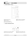 11
11
-
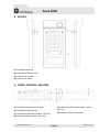 12
12
-
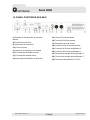 13
13
-
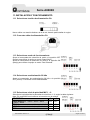 14
14
-
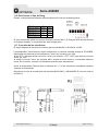 15
15
-
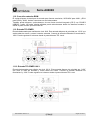 16
16
-
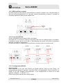 17
17
-
 18
18
-
 19
19
-
 20
20
-
 21
21
-
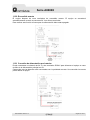 22
22
-
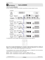 23
23
-
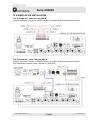 24
24
-
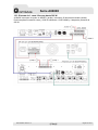 25
25
-
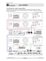 26
26
-
 27
27
-
 28
28
-
 29
29
-
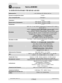 30
30
-
 31
31
-
 32
32
-
 33
33
-
 34
34
-
 35
35
-
 36
36
-
 37
37
-
 38
38
-
 39
39
-
 40
40
-
 41
41
-
 42
42
-
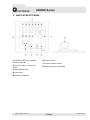 43
43
-
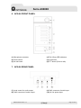 44
44
-
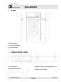 45
45
-
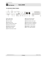 46
46
-
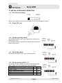 47
47
-
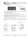 48
48
-
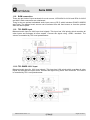 49
49
-
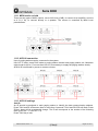 50
50
-
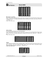 51
51
-
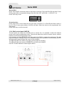 52
52
-
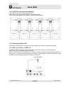 53
53
-
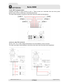 54
54
-
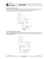 55
55
-
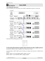 56
56
-
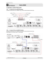 57
57
-
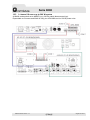 58
58
-
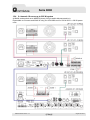 59
59
-
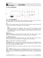 60
60
-
 61
61
-
 62
62
-
 63
63
-
 64
64
-
 65
65
-
 66
66
-
 67
67


Optimus APS-06 Manual de usuario
- Tipo
- Manual de usuario
- Este manual también es adecuado para
En otros idiomas
- English: Optimus APS-06 User manual
Documentos relacionados
-
Optimus MM-ITC Manual de usuario
-
Optimus A-5240Z6 Manual de usuario
-
-
-
-
-
-
-
-
Otros documentos
-
 Work Pro PA 60/2 Manual de usuario
-
 Work Pro PA 60/2 Manual de usuario
-
Work-pro PA 60 USB/R Manual de usuario
-
 Work Pro PA 120 USB/R Manual de usuario
-
-
 LD systems LD IMA 30 Mixing Amplifier Manual de usuario
-
LD Systems IMA30 Installation Amplifier 35W El manual del propietario
-
LD Systems IMA30 Installation Amplifier 35W El manual del propietario
-
Fonestar MAX-360Z Manual de usuario
-
Ecler HMA120 Manual de usuario


