Firman WH03041 Manual de usuario
- Categoría
- Generadores de poder
- Tipo
- Manual de usuario

P/N:330745470 Rev:00
OWNER’S MANUAL
Read all safety precautions and instructions carefully
before operating equipment.
Ensure engine is stopped and level before performing
any maintenance or service.
IMPORTANT:
Record product information to reference when ordering parts or
obtaining warranty coverage.
Serial Number:
DUAL FUEL INVERTER GENERATOR
MODEL NUMBER
WH03041
Rev Level:00
DO NOT RETURN TO
STORE!
CALL US FIRST!
CUSTOMER HOTLINE
1-844-347-6261
FOR QUESTIONS OR SERVICE
INFORMATION
Purchase Date:

Table of Contents
. . . . . . . . . . . . . . . . . . . . . . . . . . . .1
Safety Precautions . . . . . . . . . . . . . . . . . . . . .2
Unpacking The Generator. . . . . . . . . . . . . . .7
Parts Included. . . . . . . . . . . . . . . . . . . . . .7
Controls and Features. . . . . . . . . . . . . . . . . 8
Generator. . . . . . . . . . . . .. . . . . . . . . . . . . .8
Control Panel. . . . . . . . . . . . . . . . . . . . . . . 9
. . . . . . . . . . . . . 10
. . . . . . . . . . . 10
Specifications. . . . . . . . . . . . . . . . . . . . . . . . . 11
Add Engine Oil . . . . . . .. . . . . . . . . . . . . . . .12
Low Oil Shutdown . . . . . . . . . . . . . . . . . . . .12
Add Fuel . . . . . . .. . . . . . . . . . . . . . . . . . . . .13
. . . . . . . . . . .16
Grounding. . . . .. . . . . . . . . . . . . . . .. . . . . .17
System.. . . . . . . . . . . . . . . . . . . . . . .. . . . . .17
Operation . . . . . . . . . . . . . . . . . . . . . . . . .. . . . 18
Generator Location . . . . . . . . . . . . . . . . . . 18
Surge Protection . . . . . . . . . . . . .. . . . . . . .18
Starting the Generator(Recoil Start-Gas).19
Starting the Generator(Recoil Start-LPG).19
.21
.22
Connecting Electrical Loads . . . . . . . .. . . 23
Economy Control Switch. . . . . . . .. . . . . . 24
12V DC Outlet (Battery Charger).. . . . . . 24
Stopping the Engine . . . . . . . . . . . . . . . . . 25
Low Oil Shutdown . . . . . . . . . . . . . . . . . . 25
Do Not Overload Generator . . . . . . . . . . . 25
Parallel Operation. . . . . . . . . . . . . . . . . . . 26
Introduction
Battery Cable Connection
Regulator Cover Installation
Operation at High Altitude
Starting the Generator (Electric Start-Gas)
Starting the Generator (Electric Start-LPG)
Connecting to a Building’s Electrical
English Customer Service: 1-844-FIRMAN1
Maintenance And Storage. . . . . . . . . . . . . . 27
Maintenance Schedule . . . . . . . . . . . . . 27
Engine Maintenance .. . . . . . . . . . . .. . . . 28
Change Engine Oil . . .. . . . . . . . . . . . . . 28
Air Filter Maintenance. . . . . . . . . . . . . .28
Spark Plug Maintenance. . . . . . . . . . . . 29
. . . 30
Generator Maintenance . . . . . . . . . . . . . . 30
. . . . . . . . . . . . . . . 30
Charging The Generator Battery. . . . . . 31
Service and Storage . . . . . . . . . . . . . . . .. 32
Trouble Shooting . . . . . . . . . . . . . . . . . . . . .33
Parts Diagram and Parts List . . . . . . . . . . 34
Generator Parts Diagram . . . . . . . . . . . . 34
Engine Parts Diagram . . . . . . . . . .. . . . . 35
Parts List . . . . . . . . . . . . . . . . . . . . . . . . . 36
Service Information . . . . . . . . . . . . . .. . . . . 38
Warranty. . . . . . . . . . . . . . . . . . . . . . . . . . . . . 38
Inspect Muffler and Spark Arrester
Battery Replacement

Thank you for purchasing a FIRMAN generator.
This manual covers operation and maintenance of the FIRMAN generators. All information in this
publication is based on the latest production information available at the time of approval for printing.
The manufacturer reserves the right to change, alter or other wise improve the generator and this
documentation at any time without prior change.
Page 01
This manual contains safety information to make you aware of the hazards and risks associated
with generator products and how to avoid them. This generator is designed and intended only
for supplying electrical power for operating compatible electrical lighting, appliances, tools and
motor loads, and is not intended for any other purpose. It is important that you read and
understand these instructions thoroughly before attempting to start or operate this equipment.
Save these original instructions for future reference.
Important Safety Information
The manufacturer cannot possibly anticipate every possible circumstance that might involve a
hazard. The warnings in this manual and the tags and decals affixed to the unit are therefore not
all-inclusive. If you use a procedure, work method or operating technique that the manufacturer
does not specifically recommend you must satisfy yourself that it is safe for you and others. You
must also make sure that the procedure work method or operating technique that you choose
does not render the generator unsafe.
SAFETY INFORMATION
DANGER WARNING CAUTION
DANGER indicates a
potentially hazardous
situation which, if not
avoided. WILL result in
death or serious injury.
WARNING indicates a
potentially hazardous
situation which, if not
avoided, could result in
death or serious injury.
CAUTION indicates a
potentially hazardous
situation which, if not
avoided, may result in minor
or moderate personal injury,
or property damage.
Toxic Fumes
Fire Hazard
Hot Surface.
Do Not Touch the Surface.
Kickback
Risk of Electric Shock
Explosion Hazard
Rotating Parts Entanglement
Hazard
Operator’s Manual
INTRODUCTION
English Customer Service: 1-844-FIRMAN1

SAFETY PRECAUTIONS
Page 02
WARNING
POISONOUS GAS HAZARD.
•
•
•
•
•
English Customer Service: 1-844-FIRMAN1

Page 03
CORRECT USAGE
Example location to reduce risk of carbon monoxide poisoning
•ONLY use outside and downwind, far away from windows, doors and vents.
•Direct exhaust away from occupied spaces.
INCORRECT USAGE
Do not operate in any of the following locations:
Near any door, window or vent
Garage
Basement
Crawl Space
Living Area
Attic
Entry Way
Porch
Mudroom
English Customer Service: 1-844-FIRMAN1

Page 04
WHEN OPERATING EQUIPMENT
•
DO NOT tip engine or equipment at angle
which causes fuel or oil to spill.
DO NOT stop engine by moving choke
control to “Start” position.
•
•
WHEN TRANSPORTING, MOVING
OR REPAIRING EQUIPMENT
Transport/move/repair with fuel tank
EMPTY or with fuel shut OFF.valve
•
•DO NOT tip engine or equipment at angle
which causes fuel or oil to spill.
Disconnect spark plug wire.
•
WHEN STORING FUEL OR EQUIPMENT
WITH FUEL IN TANK
•
WARNING
•
•
WARNING
Generator voltage could cause
electrical shock or burn resulting
in death or serious injury.
•
WARNING
•
•NEVER start or stop engine with electrical
devices plugged in and turned on.
WARNING
Gasoline, gasoline vapors and liquid petroleum
gas(LPG) are extremely flammable and explosive
which could cause burns, fire, or explosion resulting
in death or serious injury and/or property damage.
WHEN ADDING OR DRAINING GASOLINE
Turn generator engine OFF and let it cool at
least 2 minutes before removing fuel cap.
Loosen cap slowly to relieve pressure in tank.
Fill or drain fuel tank outdoors.
•
•DO NOT overfill tank. Allow space for fuel
expansion.
If fuel spills, wait until it evaporates before
starting engine.
•
Keep fuel away from sparks, open flames,
pilot lights, heat, and other ignition sources.
Check fuel lines, tank, cap, and fittings
frequently for cracks or leaks. Replace if
necessary.
DO NOT light a cigarette or smoke.
•
•
•
•
WHEN STARTING EQUIPMENT
Ensure spark plug, muffler, fuel cap, and air
cleaner are in place.
•
DO NOT crank engine with spark plug
removed.
•Use approved transfer equipment, suitable
for the intended use, to prevent backfeed by
isolating generator from electric utility
workers.
English Customer Service: 1-844-FIRMAN1
Make certain that a LPG cylinder is not attached
to generator and is securely stowed away.
•
Do not store gasoline or LPG cylinder near
furnaces, water heaters, or any other appliances
that produce heat or have automatic ignitions.
•

Page 05
WARNING
Unintentional sparking
could cause fire or
electric shock resulting
in death or serious
injury.
WHEN ADJUSTING OR MAKING REPAIRS TO
YOUR GENERATOR
Disconnect the spark plug wire from the
spark plug and place the wire where it cannot
contact spark plug.
•
WHEN TESTING FOR ENGINE SPARK
Use approved spark plug tester.
•DO NOT check for spark with spark plug
removed.
•
WARNING
NEVER operate generator without protective
housing or covers.
DO NOT wear loose clothing, jewelry or
anything that could be caught in the starter
or other rotating parts.
Tie up long hair and remove jewelry.
•
•
•
•
•
DO NOT exceed the generator’s wattage
amperage capacity.
Start generator and let engine stabilize
before connecting electrical loads.
NOTE:
•
•
•
•
CAUTION
Exceeding generators wattage/amperage capacity
could damage generator and/or electrical devices
connected to it.
Connect electrical loads in OFF position,
then turn ON for operation.
Turn electrical loads OFF and disconnect
from generator before stopping generator.
•
•
•
DO NOT use generator with electrical cords
which are worn, frayed, bare or otherwise
damaged.
DO NOT operate generator in the rain or
wet weather.
DO NOT handle generator or electrical
cords while standing in water, while
barefoot, or while hands or feet are wet.
DO NOT allow unqualified persons or
children to operate or service generator.
•
WARNING
Exhaust heat/gases could ignite combustibles,
structures or damage fuel tank causing a fire,
resulting in death or serious injury and/or
property damage.
Contact with muffler area could cause burns
resulting in serious injury.
DO NOT touch hot parts and AVOID hot
exhaust gases.
Allow equipment to cool before touching.
It is a violation of California Public Resource
Code, Section 4442, to use or operate the
engine on any forest-covered, brush-covered,
or grass-covered land unless the exhaust
system is equipped with a spark arrester, as
defined in Section 4442, maintained in
effective working order. Other states or
federal jurisdictions may have similar laws.
Contact the original equipment manufacturer,
retailer, or dealer to obtain a spark arrester
designed for the exhaust system installed on
this engine.
Replacement parts must be the same and
installed in the same position as the original
parts.
•
•
•
•
When using generator for backup power,
notify utility company.
Use a ground fault circuit interrupter (GFCI)
in any damp or highly conductive area,
such as metal decking or steel work.
DO NOT touch bare wires or receptacles.
•
•
•
English Customer Service: 1-844-FIRMAN1

Page 06
•
•
•
•
•
Use generator only for intended uses.
If you have questions about intended use,
ask dealer or contact local service center.
Operate generator only on level surfaces.
DO NOT expose generator to excessive
moisture, dust, dirt, or corrosive vapors.
DO NOT insert any objects through cooling
slots.
If connected devices overheat, turn them off
and disconnect them from generator.
Shut off generator if:
-Electrical output is lost.
-Equipment sparks, smokes, or emits flames.
-Unit vibrates excessively.
•
•
WARNING
Medical and Life Support Uses.
In case of emergency, call 911 immediately.
NEVER use this product to power life support
devices or life support appliances.
NEVER use this product to power medical
devices or medical appliances.
Inform your electricity provider immediately
if you or anyone in your household depends
on electrical equipment to live.
Inform your electrical provider immediately
if a loss of power would cause you or anyone
in your household to experience a medical
emergency.
•
•
•
•
•
NOTE:
Improper treatment of generator could damage
it and shorten its life.
English Customer Service: 1-844-FIRMAN1
Fuel Safety
DANGER
GASOLINE AND GASOLINE VAPORS ARE HIGHLY
FLAMMABLE AND EXPLOSIVE.
Fire or explosion can cause severe burns or death.
Unintentional startup can result in entanglement,
traumatic amputation or laceration.
Gasoline expands or contracts with ambient
temperatures. Never fill the gasoline tank to
full capacity, as gasoline needs room to expand
if temperatures rise.
Gasoline can cause a fire or explosion if ignited.
Gasoline is a liquid fuel but it’s vapors can ignite.
•
•
•Gasoline is a skin irritant and needs to be cleaned
up immediately if spilled on skin or clothes.
•Gasoline has a distinctive odor, this will help
detect potential leaks quickly.
•In any gasoline fire, flames should not be
extinguished unless by doing so the fuel supply
valve can be turned OFF. This is because if a fire is
extinguished and a supply of fuel is not turned OFF,
then an explosion hazard could be created.
•
Liquid Petroleum Gas (LPG/Propane):
This generator is dual fuel and capable of running
with both gasoline and Liquid Petroleum Gas
(LPG/Propane).
•
If you smell gas: close off the gas supply. Make
sure there is no leak before using the generator.
•
•
•
•
•
•
Gasoline:
Liquid Petroleum Gas (LPG) is highly flammable
and explosive. Fire or explosion can cause severe
burns or death.
Do not use or store LPG cylinder in a building,
garage or enclosed area.
Do not check for leaks with a lighted match or
flame.
The LPG cylinder valve should be fully closed
when the generator is not in use or is running
with gasoline.
DANGER
WARNING
Device used for handling LPG must be installed
and used in strict conformance with NFPA 58
(Liquefied Petroleum Gas Code) and NFPA 54
(National Fuel Gas) and all other codes, regulations
and manufacturer recommendations.
Never use a gas container, LPG connector
hose, LPG cylinder or any other fuel item that
is damaged or appears damaged.
The LPG cylinder valve should be fully closed
when the generator is not in use or is running
with gasoline.
•
•The regulator/hose assembly and cylinder
valve must be inspected before each use for
leaks or sign of damages.

1. Engine Oil(Bottle) . . . . . . . . . . . . . . . . . . . . . . . 1
2. Oil Funnel . . . . .. . . . . . . . . . . . . . . . . . . . . . . . . . 1
3. Wrench for Spark Plug . . . . . . . . . . . . . . . . . . . .1
4. Screwdriver. . . . . . . . . . . . . . . . . . . . . . . . . . . . . . .1
5. Battery Charge Cable . . . . . . . . . . . . . . . . . . . . .1
6. Manual. . . . . . . . . . . . . . . . . . . . . . . . . . . . . . . . . . 1
7. Quick Reference Guide . . . . . . . . . . . . . . . . . . . 1
8. Battery Float Charger(12V DC) . . . . . . . . . . . 1
LPG Regulator/ Hose Assembly. . . . . . . .. . . . 19.
2
1
Quick
Reference
Guide
3
Manual
6
4
57
8
Page 07
English Customer Service: 1-844-FIRMAN1
UNPACKING THE GENERATOR
•
•
Parts Included
Your gasoline powered generator ships with
the following parts:
If you smell gas: close off the gas supply. Spray
a soapy water solution to check all connections
for leaks before attempting to use generator.
Contact a qualified technician to inspect and
repair the LPG system if a leak found before
using the generator.
•
CAUTION
LPG under pressure is highly flammable and
can cause a fire or explosion if ignited.
LPG is heavier than air and can accumulate in
confined spaces and low places in the event
of a leak.
LPG has a distinctive odor to help detect
potential leaks.
Do not allow children to tamper or play with
the LPG cylinder.
In the event of an LPG fire, flames should not
be extinguished unless by doing so the fuel
supply valve can be turned off. If the fire is
extinguished and a supply of fuel is not turned
off, an explosion hazard greater than the fire
hazard could be created.
Keep a fire extinguisher near the generator all
the time.
Always keep the LPG cylinder in an upright
position.
Do not subject LPG cylinder to excessive heat.
Contact with liquid contents of the cylinder
will cause freeze burns to the skin.
An LPG cylinder not connected for use shall
not be stored in the vicinity of the generator.
When transporting and storing, turn off the
cylinder valve and fuel selector switch, and
disconnect the cylinder.
•
•
•
•
•
•
•
•
•
•
•
9

Page 08
CONTROLS AND FEATURES
Generator
*We are always working to improve our products. Therefore, the enclosed product may differ
slightly from the image on this page.
1- Fixed
2- Fuel Cap
3- LPG Hose Quick Connect Inlet
4- Recoil Starter
5- Never Flat Wheel
6- Control Panel
7- Muffler/Spark Arrester
Carrying Handle
English Customer Service: 1-844-FIRMAN1
⑨
②
③
①
④
⑤
⑥
⑦
①
⑧
8- Folding Handle
9- Maintenance Cover – Oil filler and
air filter access.
10- LPG Hose with Regulator
11- Spring Clamp to Hang Regulator
on Handle
⑪
⑩

Page 09
Control Panel
1
2
3
4
6
Total power drawn from all receptacles must not exceed the name plate rating.
NOTE:
English Customer Service: 1-844-FIRMAN1
5
7
Oil Warning Indicator Light – Check oil level when
this light turns “ON”. Engine will not run when
indicator is lit.
8
Overload Indicator Light – This light turns “ON”
when the generator is overloaded and will cut
power to the receptacles.
9
Output Ready Indicator Light – Remains “ON”
during normal operating conditions. Shuts “OFF”
when generator is overloaded.
10
Economy Control Switch
The Economy Control switch can be activated in order to
minimize fuel consumption and noise while operating the
unit during times of reduced electrical output, allowing
the engine speed to idle during periods of non-use. The
engine speed returns to normal when an electrical load is
connected. When the economy switch is off, the engine
runs at normal speed continuously.
When the oil falls below the minimum level, the oil
warning indicator light comes on and the engine
stops automatically. The engine will not start until
the proper amount of oil is in the crank case.
The green AC Power Indicator Light comes on
when the engine starts and generates power.
If the engine overload indicator light comes on, the
generator’s wattage / amperage capacity has been
exceeded by connected electrical devices or by a
power surge. When this occurs, the green AC Power
Indicator Light(Item 7) will go off. The engine will
continue to run, but the red Engine Overload Indicator
Light will stay on and power will no longer be supplied
to connected electronic devices.
3-1 Data-Minder(Multi-Meter) – Push the SELECT
button to show the Voltage, Hertz and running hours.
120V, 20A Duplex – (NEMA 5-20R) 20 Amp of current
may be drawn from this 120 Volt receptacle.
120V, 30A RV (NEMA TT-30R) Maximum full load
30 Amp current may be drawn from this 120 Volt receptacle.
–
Engine Switch – To start engine, press the switch
in the “RUN”(l) position.
DC 5V 2.1A USB Outlet
Circuit Breakers – The receptacles are protected by
an AC circuit protector. If the generator is overloaded
or an external short circuit occurs, the circuit protector
will trip. If this occurs, disconnect all electrical loads and
try to determine the cause of the problem before
attempting to use the generator again. If overloading
causes the circuit protector to trip, reduce the load.
Note: Continuous tripping of the circuit protector
may cause damage to generator or equipment. The
circuit protector may be reset by pushing the button
of the protector.
6
9
7
8
10 11
12
13
15
14
1
2
34
5
16
17
18
19
20
21
Battery Power Restore Switch
11
22

Page 10
English Customer Service: 1-844-FIRMAN1
12
14
15
Parallel Operation Outlets - These outlets are used
for connecting two FIRMAN inverter generators for
parallel operation. A FIRMAN parallel kit(optional
equipment) is required for parallel operation.
12V DC outlet – 8.3 Amp of DC current may be drawn
from this receptacle.
Use this outlet to charge 12V automotive type
batteries ONLY. See 12V DC outlet (Battery
Charger) section.
16
DC Circuit Breaker - The circuit protector may be reset
by pushing the button of the protector.
Ground Terminal – Consult an electrician for local
grounding regulations.
17
18
Outlet Cover - Protect the receptacles from dust
and debris.
LPG Regulator Solenoid Port
Recoil Stater
Choke Button
12V DC Battery Charger Port - Plug the 120 Volt
AC charger into this port to charge the generator
battery.
13
19
Battery Cable Connection
1.Unscrew the maintenance cover by provided
screwdriver.
2. Cut wire tie that is binding the black battery
cables A and B.
3. Insert the male connector of cable A into
female connector of cable B.
4. Reattach the maintenance cover.
Follow below instruction to connect battery to
the generator:
LPG Hose Quick Connect Inlet
20
21
22
Fuel Selector Switch Used to select and turn on
gas or LPG fuel source.
-
Regulator Cover Installation
A
B
C
D
Follow below instruction to install the LPG
regulator cover:
1, Place the LPG regulator cover A over the LPG
regulator B.
2, Use M5X14(QTY:3) C and M5X35(QTY:1) D
screws to tighten the LPG regulator cover.

Page 11
SPECIFICATIONS
AN IMPORTANT MESSAGE ABOUT TEMPERATURE:
Your Firman Power Equipment product is designed and rated for continuous operation at
ambient temperatures up to 40°C (104°F). When your product is needed, your product may be
operated at temperatures ranging from -15°C (5°F) to 50°C (122°F) for short periods. If the
product is exposed to temperatures outside this range during storage, it should be brought back
within this range before operation. In any event, the product must always be operated outdoors,
in a well-ventilated area and away from doors, windows and other vents.
When operated above 77°F(25°C) there may be a decrease in power.
Maximum wattage and current are subject to and limited by such factors as fuel BTU content
ambient temperature, altitude, engine condition and etc. Maximum power decreases about
3.5% for each 1,000 feet above sea level; and will also decrease about 1% for each 10°F(6°C)
above 60°F(16°C) ambient temperature.
•
•
Model
Rated AC Voltage
Phase
Power Factor
Voltage regulator
Alternator Type
Running Watts
Starting Watts
Engine
Engine Type
Displacement
Low Oil Shutdown
Ignition System
Starting System
Fuel
Capacity Fuel Tank
Lubricating Oil Capacity
Carburetor Type
Air Cleaner
P.T.O. shaft rotation
120V
WH03041
3300(GASOLINE)/3000(LPG)
Digital
Single Phase
1
Single Cylinder, 4-Stroke OHV Air Cooled
171 cc
Breakless Ignition Type, Flywheel Magneto
Unleaded Automotive Gasoline/LPG
1.8 Gallon
20.3 oz(0.6L)
Counter Clockwise (Facing P.T.O.)
Float
Polyurethane Type
YES
FIRMAN
Rated Fequency 60Hz
Oil Type
See “Add Engine Oil” Section
English Customer Service: 1-844-FIRMAN1
Magneto Inductor
Recoil
Total Harmonic Distortion(THD) <3%
AC Grounding System
Floating Neutral
3000(GASOLINE)/2700(LPG)

Add Engine Oil
Page 12
DO NOT attempt to crank or start the engine
before it has been properly filled with the
recommended type and amount of oil. Damage
to the generator as a result of failure to follow
these instructions will void your warranty.
1.Place generator on a flat and level surface.
2.Loosen the cover screw and remove the
maintenance cover.
NOTE:
The recommended oil type is 10W-30 automotive
oil. However outdoor temperatures will determine
the space proper oil viscosity for the engine. Use the
chart to select the best for the outdoor temperature
range expected.
The engine is equipped with a low oil shut-off and
will stop when the oil level in the crankcase falls
below the threshold level.
NOTE:
We consider the first 5 hours of run time to be
the break-in period for the unit. During the break
in period stay at or below 50% of the running
watt rating and vary the load occasionally to allow
stator windings to heat and cool. Adjusting the
load will also cause engine speed to vary and help
seat piston rings.
CAUTION
The unit is equipped with a low oil shutdown.If
the oil level becomes lower than required,the
sensor will activate a warning device or stop the
engine.
If generator shuts off and the oil level is within
specifications, check to see if generator is sitting
at an angle that forces oil to shift. Place on an
even surface to correct this. If engine fails to
start, the oil level may not be sufficient to
deactivate low oil level switch. Make sure the
sump is completely full of oil.
5.Replace oil fill cap/dipstick and fully tighten.
6.Reinstall maintenance cover and tighten screws.
4.Using oil funnel, slowly pour contents of
provided oil bottle into oil fill opening to the
"H" mark on dipstick. Be careful do not
overfill. Overfilling with oil could cause the
engine to not start or hard starting.
Low oil shutdown
Degrees Celsiusº(Outside)
Full Synthetic 5W-30
Degrees Fahrenheitº(Outside)
5W-30 10W-40
10W-30
CAUTION
English Customer Service: 1-844-FIRMAN1
3.Remove oil fill cap/dipstick .
7.Oil Level should be checked prior to each use or
at least 8 hours or operation. Keep oil level maintained.
DRAIN PLUG
HIGH
H
H
L

Add Fuel
Page 13
Fuel must meet these requirements:
•Clean, fresh, unleaded gasoline.
Use regular UNLEADED gasoline with the
generator engine with a minimum 87 octane
/ 87 AKI (91 RON).
For high altitude use, see "Operation at High
Altitude".
Do not use gasoline with more than 10%
alcohol such as E85 or ethanol.
•
•
Failure to follow Operator's Manual for fuel
recommendations voids warranty.
Avoid generator damage.
DO NOT use unapproved gasoline such as E85.
DO NOT mix oil in gasoline.
DO NOT modify engine to run on alternate fuels.
•
•
•
WARNING
Fuel and its vapors are extremely flammable
and explosive which could cause burns, fire or
explosion resulting in death, serious injury
and/or property damage.
WHEN ADDING FUEL
Fill fuel tank outdoors.
DO NOT overfill tank. Allow space for fuel
expansion. If the tank is overfilled, fuel
can overflow onto a hot engine and cause fire
or explosion. Wipe up any spilled fuel
immediately.
If fuel spills, wait until it evaporates before
starting engine.
Keep fuel away from sparks, open flames,
pilot lights, heat, and other ignition sources.
Check fuel lines, tank, cap and fittings
frequently for cracks or leaks. Replace if
necessary.
DO NOT light a cigarette or smoke when
filling the fuel tank.
•
•
•
•
1.Clean area around fuel fill cap, remove cap.
2.Slowly add unleaded fuel to fuel tank. Be
careful not to fill above the red fuel level
indicator . This allows adequate space for
fuel expansion.
3.Install fuel cap and let any spilled fuel
evaporate before starting engine or wipe up
any spilled gasoline.
English Customer Service: 1-844-FIRMAN1
CAUTION
Slowly add unleaded gasoline to fuel tank.
Do not overfill tank.
•
•
•Do not fill above the red fuel level indicator.
This will allow expansion in hot weather and
prevent overflow.
Fuel Level Indicator
IMPORTANT: It is important to prevent gum
deposits from forming in fuel system parts such
as the carburetor, fuel hose or tank during
storage. Alcohol-blended fuels (called gasohol,
ethanol or methanol) can attract moisture, which
leads to separation and formation of acids during
storage. Acidic gas can damage the fuel system
of an engine while in storage. To avoid engine
problems, the fuel system should be emptied
before storage of 30 days or longer. See the
" Long Term Storage" section. Never use engine
or carburetor cleaner products in the fuel tank
as permanent damage may occur.
1.Gasoline
2-Connecting Liquid Petroleum Gas
(LPG/Propane) Cylinder
•
•
Liquid Petroleum Gas (LPG) is highly flammable
and explosive. Fire or explosion can cause severe
burns or death.
Do not use or store LPG cylinder in a building,
garage or enclosed area.
DANGER
•Do not place the LPG cylinder in the path of
muffler outlet.

Page 14
English Customer Service: 1-844-FIRMAN1
•Never use a gas container, LPG connector
hose, LPG cylinder or any other fuel item that
is damaged or appears damaged.
The LPG cylinder valve should be fully closed
when the generator is not in use or is running
with gasoline.
•
•The regulator/hose assembly and cylinder
valve must be inspected before each use for
leaks or sign of damages.
Use only 20 or 30 lb capacity cylinders with
Type 1, right hand Acme threads with this
generator. Verify the re-qualification date
on the tank has not expired. Do not use rusted
or damaged cylinders.
All new cylinders must be purged of air and
moisture prior to filling. Used cylinders that
have not been plugged or kept closed must
also be purged. The purging process should
be done by your propane gas supplier.
Do not connect or disconnect the LPG cylinder
in enclosed area.
Do not install or replace the LPG cylinder near
open flames, pilot lights, or sparking electrical
equipment such as power tools, welders and
grinders.
If you smell gas: close off the gas supply. Spray
a soapy water solution to check all connections
for leaks before attempting to use generator.
Contact a qualified technician to inspect and
repair the LPG system if a leak found before
using the generator.
•
•WARNING
Device used for handling LPG must be installed
and used in strict conformance with NFPA 58
(Liquefied Petroleum Gas Code) and NFPA 54
(National Fuel Gas) and all other codes, regulations
and manufacturer recommendations.
If you smell gas: close off the gas supply. Make
sure there is no leak before using the generator.
•
•
•
Do not check for leaks with a lighted match or
flame.
The LPG cylinder valve should be fully closed
when the generator is not in use or is running
with gasoline.
D(Regulator Assembly)
A(LPG Regulator/Hose Assembly)
B(LPG Regulator
solenoid plug)
C(Quick Connect
Fitting)

Page 15
English Customer Service: 1-844-FIRMAN1
Remove the cap/plug and attach the quick
connect fitting C to the quick connect in let
located on the control panel.
Attach the LPG regulator solenoid plug B to
the LPG regulator solenoid port located on
the control panel.
Remove the safety cap/plug from the cylinder
valve and attach the LPG regulator assembly
D to the LPG cylinder.
Tighten the nut by hand clock wise to a positive
stop.
Do not use a wrench to tighten .
Use of wrench may damage quick closing coupling
nut and result in a hazardous condition.
NOTE:
Do not use tape or any type sealant to seal the
LPG hose connections.
Always position the cylinder so the connection
between the valve and the regulator won’t cause
bends or kinks in the hose.
Spray a soapy water solution (one part liquid
detergent and one part water) to check all
connections for leaks before attempting to
use generator. Slowly open the cylinder valve.
A leak exists if bubbles appear or grow larger
in size or number. This must be corrected before
using the generator. Contact your local
Authorized Service Facility for assistance. Do
not attempt to make repairs yourself.
You must use the supplied regulator/hose
assembly for safe operation.
Do not check for leaks with a lighted match or flame.
Do not light or smoke cigarettes.
Check the fuel system periodically for leaks
or signs of damages.

Page 16
English Customer Service: 1-844-FIRMAN1
Operation at High Altitude
At altitudes over 5,000 feet(1524 meters), a
minimum 85 octane / 85 AKI (89 RON) gasoline
is acceptable.
The density of air at high altitude is lower
than at sea level. Engine power is reduced
as the air mass and air-fuel ratio decrease.
Engine power and generator output will be
reduced approximately 3.5% for every 1000 feet
of elevation above sea level. This is a
natural trend and cannot be changed by
adjusting the engine. At high altitudes
increased exhaust emissions can also result
due to the increased enrichment of the air
fuel ratio.
Other high altitude issues can include hard
starting, increased fuel consumption and
spark plug fouling. To a l l e v i a t e hi gh
al titud e issues o ther tha n the n atura l
power loss, FIRMAN can provide a high
altitude carburetor main jet. The alternative
The part number and recommended minimum
altitude for the application of the high
altitude carburetor main jet is listed in the
table below.
main jet and installation instructions can be
obtained by contacting Customer Support.
Installation instructions are also available in the
Technical Bulletin area of the FIRMAN internet site.
OPEN
WARNING
3-Permanent Connection to a large
Propane supply tank:
In the instance that you would need to connect
your generator to a large propane Supply tank,
larger than 20 or 30 lb DOT cylinder, it is
recommended to contact your Gas Equipment
Company. Various equipment for use with LPG,
is required for proper conformance to all NFPA
regulations. Your Gas Equipment Company can
help you select and install the proper regulator,
fittings and connections to meet all the Codes
and manufacturer regulations. Each installation
may be different and will required proper equipment.
Contact your Gas Equipment Company to assure
that you are meeting all NFPA 58 (Liquefied
Petroleum Gas Code) and NFPA 54 (National Fuel
Gas) Codes.
When transporting and storing, turn off the
cylinder valve and fuel selector switch, and
disconnect the cylinder.
Contact with liquid contents of the cylinder
will cause freeze burns to the skin.
•
An LPG cylinder not connected for use shall
not be stored in the vicinity of the generator.
•
•
•Always keep the LPG cylinder in an upright
position.
Do not subject LPG cylinder to excessive heat.
•
In the event of an LPG fire, flames should not
be extinguished unless by doing so the fuel
supply valve can be turned off. If the fire is
extinguished and a supply of fuel is not turned
off, an explosion hazard greater than the fire
•
hazard could be created.
•Keep a fire extinguisher near the generator
all the time.
Altitude main jet 1
Altitude main jet 2
171cc
330717004
330717005
Altitude
3000-6000Feet
6000-8000Feet
LPG under pressure is highly flammable and
can cause a fire or explosion if ignited.
CAUTION
•
LPG is heavier than air and can accumulate in confined
spaces and low places in the event of a leak.
LPG has a distinctive odor to help detect
potential leaks.
•
•
Do not allow children to tamper or play with
the LPG cylinder.
•

Page 17
Use approved transfer equipment to prevent
backfeed by isolating generator from electric
utility workers.
When using generator for backup power, notify
utility company.
Use a ground fault circuit interrupter (GFCI) in
any damp or highly conductive area, such as
metal decking or steel work.
DO NOT touch bare wires or receptacles.
DO NOT use generator with electrical cords
which are worn,frayed, bare or otherwise
damaged.
DO NOT operate generator in the rain or wet
weather.
DO NOT handle generator or electrical cords
while standing in water, while barefoot, or
while hands or feet are wet.
DO NOT allow unqualified persons or children
to operate or service generator.
Connecting to a Building's Electrical System
Connections for standby power to a building's
electrical system must be made by a qualified
electrician. The connection must isolate the
generator power from utility power or other
alternative power sources and must comply
with all applicable laws and electrical codes.
WARNING
Generator voltage could cause
electrical shock or burn resulting
in death or serious injury.
•
•
•
•
•
•
•
•
English Customer Service: 1-844-FIRMAN1
Grounding
The National Electric Code requires your generator
must be properly connected to an appropriate
ground to help prevent electric shock.
Failure to properly ground the
generator can result in electric
shock.
WARNING
A ground terminal connected to the frame of
the generator has been provided on the control
panel. For remote grounding, connect of a
length of heavy gauge (12 AWG minimum)
copper wire between the generator ground
terminal and a copper rod driven into the
THERE IS A PERMANENT CONDUCTOR BETWEEN
THE GENERATOR (STATOR WINDING) AND THE
FRAME.
ground. We strongly recommend that you
consult with a qualified electrician to ensure
compliance with local electrical codes.

Page 18
Surge Protection
Voltage fluctuation may impair the proper
functioning of sensitive electronic equipment.
Electronic devices, including computers and
many programmable appliances use components
that are designed to operate within a narrow
voltage range and may be affected by momentary
voltage fluctuations. While there is no way to
prevent voltage fluctuations, you can take steps
to protect sensitive electronic equipment.
Install UL1449, CSA-listed, plug-in surge
suppressors on the outlets feeding your
sensitive equipment. Surge suppressors come
in single- or multi-outlet styles. They’re
de s i g n e d to pr o t e ct a g a i n s t vir t u a ll y
all short-duration voltage fluctuations.
Operate this product ONLY outside far away
from windows, doors and vents to reduce
the risk of carbon monoxide gas from
accumulating and potentially being drawn
towards occupied spaces.
•
•Install battery-operated carbon monoxide
alarms or plug-in carbon monoxide alarms
with battery back-up according to the
manufacturer’s instructions. Smoke alarms
cannot detect carbon monoxide gas.
•
DO NOT run this product inside homes,
garages, basements, crawlspaces, sheds, or
other partially-enclosed spaces even if using
fans or opening doors and windows for
ventilation. Carbon monoxide can quickly
build up in these spaces and can linger for
hours, even after this product has shut off.
•ALWAYS place this product downwind and
point the engine exhaust away from
occupied spaces. If you start to feel sick,
dizzy, or weak while using this product, shut
it off and get to fresh air RIGHT AWAY. See a
doctor. You may have carbon monoxide
poisoning.
CAUTION
English Customer Service: 1-844-FIRMAN1
OPERATION
Generator Location
Make sure you review each warning in order to
prevent fire hazard.
Keep area clear of inflammables or other
hazardous materials.
Select a site that is dry, well ventilated and
protected from the weather.
Keep exhaust pipe clear of foreign objects.
Keep generator away from open flame.
Keep generator on a stable and level surface.
WARNING
WARNING
POISONOUS GAS HAZARD.
Engine exhaust contains carbon
monoxide, a poisonous gas that
could kill you in minutes. You
CANNOT smell it, see it, or taste
it. Even if you do not smell exhaust
fumes, you could still be exposed
to carbon monoxide gas.
Avoid other generator hazards.
READ MANUAL BEFORE USE.
Do not block generator air vents with paper or
other material.
CAUTION
Tilting can cause fuel spillage.

Page 19
English Customer Service: 1-844-FIRMAN1
Starting the Generator (Recoil Start-Gasoline)
1. Before starting the generator, check for loose
or missing parts and for any damage which
may have occurred during shipment.
2. Check oil level and fuel.
9. Pull the starter cord slowly until resistance is
felt and then pull rapidly.
11. Allow generator to run at no load for few
minutes upon each initial start-up to permit
engine and generator to stablize.
10. Push the choke button to the “RUN” position.
6. Flip the engine switch to the “RUN"(l) position.
5. Disconnect all electrical loads from the
generator. Never start or stop the generator
with electrical devices plugged in or turned
on.
3. Make sure the LPG cylinder knob is fully closed.
8. Pull the choke lever out to the "CHOKE" position.
7. Push the battery power restore switch for about
3 seconds and then release.
Starting the Generator (Recoil Start-LPG)
NOTE: hen the fuel
selector switch is in “GAS” position(4:30 o’clock).
To close this valve, turn the slector switch to the
“ LPG” position (1:30 o’clock).
The gasoline valve is OPEN, w
NOTE: The generator will NOT start with LPG without
battery power or an appropriate connection.
1. Before starting the generator, check for loose
or missing parts and for any damage which
may have occurred during shipment.
4. Turn the fuel selector switch to “GAS” position(4:30 o’clock).

Page 20
English Customer Service: 1-844-FIRMAN1
11. Push the choke button to the “RUN” position.
7. Flip the engine switch to the “RUN"(l) position.
6. Disconnect all electrical loads from the generator.
Never start or stop the generator with electrical
devices plugged in or turned on.
5. Turn the fuel selector switch to “LPG” position(1:30 o’clock).
9. Pull the choke lever out to the "CHOKE" position.
8. Push the battery power restore switch for about
3 seconds and then release.
4. Fully open the LPG cylinder knob.
Use your fingers, slide the outer barrel back on
the LPG quick connect hose fitting. While the outer
barrel is in the back position, insert the LPG hose
(included) into the inlet and release the outer barrel.
The barrel will automatically return and lock the
hose in the inlet.
10. PULL TO-PRIME:-
Pull the starter cord 1-2 times. Pull slowly until
resistance if felt and then pull rapidly.
12. PULL TO RUN:- -
Pull the starter cord slowly until resistance if felt
and pull rapidly to run the unit.
If the engine fails to start in 1-2 pulls with choke in the
“RUN” position, then move choke lever to “START”
position and repeat the “PULL-TO-PRIME” step.
3. Connect the regulator(A) to both LPG cylinder
and generator. Connect the power cord(B) to the
LPG regulator port. See “Connecting liquid Petroleum
Gas(LPG/Propane) ” section on page 13, 14,15.Cylinder
2. Check oil level.

Page 21
English Customer Service: 1-844-FIRMAN1
13. Allow generator to run at no load for few
minutes upon each initial start-up to permit
engine and generator to stablize.
Starter cord kickback(rapid
retraction) will pull hand and arm
toward engine faster than you can
let go which could cause broken
WARNING
When starting engine, pull cord slowly until
resistance is felt and then pull rapidly to avoid
kickback.
bones, fractures, bruises, or sprains resulting in
serious injury.
If engine starts after 3 pulls but fails to run, or if
unit shuts down during operation, make sure
unit is on a level surface and check for proper
oil level in crankcase. This unit may be equipped
with a low oil protection device. If so, oil must
be at proper level for engine to start.
Keep choke lever in “CHOKE” position for only 1
pull of the recoil starter. After first pull, move
choke lever to the “RUN” position for up to the
next 3 pulls of the recoil starter. Too much
choke leads to sparkplug fouling/engine
flooding due to the lack of incoming air. This
will cause the engine not to start.
3.Plug in and turn on the desired 120 Volt AC,
single phase, 60Hz electrical loads. It is
better to attach the item with largest load first.
Connecting Electrical Loads
1.Let engine stabilize and warm up for a few
minutes after starting.
2.Ensure circuit breaker on control panel is in
on position.
This unit has been pretested and adjusted to
handle its full capacity. Before starting the
generator, disconnect all load. Apply load only
after generator is running. Voltage is regulated
via the engine speed adjusted at the factory for
correct output. Readjusting will void warranty.
CAUTION
When applying a load, do not exceed the maximum
wattage rating of the generator when using one or
more receptacles. Also, do not exceed the amperage
rating of any one receptacle.
Do not apply heavy electrical load during break-in
period (the first five hours of operations).
Connecting a generator to your electric utility
company’s power lines or to another power
source may be against the law. In addition this
action, if done incorrectly, could damage your
generator and appliances and could cause
serious injury or even death to you or a utility
worker who may be working on nearby power
lines. If you plan to run a portable electric
generator during an outage, please notify your
electric utility company immediately and
remember to plug your appliances directly into
the generator. Do not plug the generator into
any electric outlet in your home. Doing so could
create a connection to the utility company
power lines. You are responsible for ensuring
that your generator’s electricity does not feed
back into the electric utility power lines.
If the generator will be connected to a building

Page 24
English Customer Service: 1-844-FIRMAN1
electrical system, consult your local utility
company or a qualified electrician. Connections
must isolate generator power from utility
power and must comply with all applicable laws
and codes.
Economy Control Switch
The Economy Control switch can be activated in
order to minimize fuel consumption and noise
while operating the unit during times of reduced
electrical output, allowing the engine speed to
idle during periods of non-use. The engine speed
returns to normal when an electrical load is
connected. When the economy switch is off, the
engine runs at normal speed continuously.
WARNING
For periods of high electrical load or momentary
fluctuations, the Economy Control Switch should
be turned OFF.
12V DC Outlet (Battery Charger)
The 12V DC outlet is ONLY to be used with the
supplied 12V battery charging cable. The DC
output is unregulated and will damage other
12V DC products.
The amount of current flowing will depend on the
charging voltage and battery's state of charge. As
the battery becomes more fully charged, the output
current to the battery decreases and nearly becomes
constant. Taper chargers are intended to be used
with the provision that they will be disconnected
from the battery after a maximum time on charge.
Normally a period of 30 to 120 minutes is sufficient
to recharge a weak battery. The charge level of the
battery should be checked periodically.
1. Before connecting the battery charging cable
to a battery that is installed in a vehicle, disconnect
the vehicle battery ground cable from the
negative (–) battery terminal.
Do not continue to charge a battery that becomes
hot or is fully charged.
2. Plug the battery charging cable into the DC
receptacle of the generator.
3. Connect the red (+) battery charger lead to the
red (+) battery terminal.
4. Connect the black (–) battery charger lead to
the black (–) battery terminal.
5. Start the generator.
NOTE:
When the battery circuit is in use the AC capacity
is reduced by 100 watts. Make sure the combined
load is within the rated limits.
WARNING
Do not continue to charge a battery that becomes
hot or is fully charged.
CAUTION
Storage batteries give off EXPLOSIVE hydrogen
gas while charging. Do not allow smoking, open
flames, sparks, or spark producing equipment
in the area while charging.
WARNING
Do not start the vehicle while the battery charging
Cable is connected and the generator is running.
It will not give the battery a boost of power. The
Vehicle or the generator may be damaged. Charge
only vented wet lead acid batteries. Other types
of batteries may burst, causing personal injury
or damage.
Battery electrolyte fluid is comprised of sulfuric
acid that can be very dangerous and cause severe
burns. Do not allow this fluid to contact eyes, skin,
clothing, etc. If contact or spillage does occur,
flush the area with water immediately.
WARNING
For use with 12V direct current outlet, always
keep the ECO mode deactivated (OFF Position).
•
•You can use the 12V direct current outlet and
the 230V current at the same time, but keep
the ECO mode deactivated (OFF Position) at
all times.

Page 25
English Customer Service: 1-844-FIRMAN1
A DC circuit protector has been provided to
protect the circuit from overloads. If an overload
occurs, the circuit protector will trip. The circuit
protector may be reset by pushing the button of
the protector.
DC CIRCUIT PROTECTOR
Charging a large capacity battery or a totally
discharged battery may cause the DC breaker to
turn off. In these cases, a separate battery charger
unit connected to an AC power source is
recommended instead of the DC receptacle on
the generator.
Stopping the Engine
1. Turn off and remove entire electrical loads.
Never start or stop the generator with
electrical devices plugged in or turned on.
Let the generator run at no-load for two minutes to stabilize
internal temperatures of the engine and generator.
2. Flip the engine switch to“OFF”(O) position.
Low Oil Shutdown
If the engine oil drops below a preset level, an
oil switch will stop the engine. Check oil level
with dipstick.
If oil level is between the LOW and HIGH mark on
dipstick:
1.Add oil to bring level to HIGH mark.
2.Restart engine and if the engine stops again
a low oil condition may still exist. DO NOT try
to restart the engine.
3.Contact an Authorized FIRMAN Service Dealer.
4.DO NOT operate engine until oil level is
corrected.
Do Not Overload Generator
Overloading a generator in excess of its rated
wattage capacity can result in damage to the
generator and to connected electrical devices.
To prolong the life of your generator and
attached devices, follow these steps to add
electrical load:
1.DO NOT try to restart the engine.
2.Contact an Authorized FIRMAN Service Dealer.
3.DO NOT operate engine until oil level is corrected.
If oil level is below the LOW mark on dipstick:
DO NOT stop engine by moving choke control
to “START” position.
Important: Always ensure that the
is in the “OFF” position when the engine
is not in use.
fuel selector
switch
explosion resulting in death, serious injury
and/or property damage.
If the engine will not be used for a period of two
weeks or longer, please see the Storage section
for proper engine and fuel storage.
3. Turn the fuel selector switch to “ ” position
(1:30 o’clock). The gasoline valve is close on this
position.
LPG
4. Fully close the LPG cylinder knob.
If a cover is used, do not install until unit has cooled.
WARNING
Fuel and its vapors are extremely flammable and
explosive which could cause burns, fire or
NOTE: Disconnect the LPG cylinder from the
generator during transportation.

Page 26
English Customer Service: 1-844-FIRMAN1
Observing frost on LPG and regulators
is common during operation and normally is not
an indication of a problem. As LPG vaporizes and
travels from the tank to the generator engine it
expands. The amount of frost that forms can be
affected by the size of the cylinder, the amount
of fuel being used, the humidity of the air and other
operating conditions. In unusual situations this
frost may eventually restrict the flow of LPG gas
cylinders
NOTE:
to the generator resulting in deteriorating
performance. For example, if the tank temperature
is reduced to a very low level then the rate at which
the LPG vaporizes is also reduced and may not
provide sufficient fuel flow to the engine. This is
not an indication of a problem with the generator
but only a problem with the flow of gas from the
LPG cylinder. If generator performance seems
to be deteriorating at the same time that ice
formation is observed on tank valve, hose or
regulator then some actions may be taken to
eliminate this symptom. In these rare situations
it can be helpful to reduce or eliminate the cold
fuel system effects by doing one of the following:
The LPG cylinder can be temporarily warmed
by pouring warm water over the top of the
cylinder.
Exchanging fuel tanks to allow the first tank
to warm up, repeating as necessary
•
Placing the LPG cylinder at the end of the
generator near the handle, where engine fan
air flows out from the generator. This air is
slightly heated by flowing over the engine.
•
•
DO NOT PLACE THE LPG CYLINDER IN THE PATH
OF MUFFLER OUTLET.
DANGER
Muffler
Parallel Operation
1. Disconnect any electronic devices, and then
stop the engine.
2. Reduce the total wattage of connected
electronic devices until it is within the generator’s
rated output.
3. Inspect the Air Inlet and Control Panel for any
blockage. Remove blockage if found.
4. Restart Engine.
How to Correct
CAUTION:
DO NOT disconnect parallel cables while generator
is running.
Any two FIRMAN inverter generator with parallel
port including two FIRMAN inverter model WH03041
can be paralleled to increase the total available
electrical power to 5500 Watts (on gasoline
application). A FIRMAN Parallel kit (not included) is
Overload Operation
The overload indicator light will turn on and cut
power to the receptacles after 30 seconds when
the load exceeds 3080W(approximately).
The overload indicator light will turn on and cut
power to the receptacles after 2 seconds when
the load exceeds 3150W(approximately).
For Kit availability, call customer Service at 1-844-
347-6261 or visit: www.firmanpowerequipment.com.
required for parallel operation.
1. Start the generator with no electrical load
attached.
2. Allow the engine to run for several minutes
to stabilize.
3. Plug in and turn on the first item. It is best to
attach the item with the largest load first.
4. Allow the engine to stabilize.
5. Plug in and turn on the next item.
6. Allow the engine to stabilize.
7. Repeat steps 5-6 for each additional item.

MAINTENANCE AND STORAGE
Page 27
General Recommendations
Regular maintenance will improve the performance and extend the life of the generator. See any
authorized dealer for service.
The generator's warranty does not cover items that have been subjected to operator abuse or
negligence. To receive full value from the warranty, the operator must maintain the generator as
instructed in this manual.
Some adjustments will need to be made periodically to properly maintain your generator.
All service and adjustments should be made at least once each season. Follow the requirements
in the Maintenance Schedule chart above.
Notice Once a year you should clean or replace the spark plug and replace the air filter. New
spark plugs and clean air filter assure proper fuel-air mixture and help your engine run better
and last longer.
English Customer Service: 1-844-FIRMAN1
MAINTENANCE SCHEDULE
ITEM NOTES Daily(Before
operation)
Initial
25 hours
Every
50 hours
Every
100 hours
(or annual)
Fittings/
Fasteners
Spark Plug
Engine Oil
Air Filter
Fuel Line
Exhaust
System
Engine
Check condition. Adjust gap
and clean. Replace if necessary.
Check oil level.
Clean, replace if necessary.
Check for leakage. Retighten or
replace gasket if necessary.
Check adjust valve clearance.
Clean combustion chamber.
Check. Replace if necessary.
Check fuel hose for cracks or other
damage. Replace if necessary.
√
√
√
√
√
√
√
√
√
√
Replace.
Check spark arrester screen.
Clean/Replace if necessary.
√
Check for damage and leaks.
Replace if necessary.
LPG Regulator
/Hose Assy.
Every
250 hours
√
To be performed by knowledgable/experienced owner or by authorized service center.
*
*
*

Page 28
English Customer Service: 1-844-FIRMAN1
ENGINE MAINTENANCE
Air Filter Maintenance
Use fresh and high quality lubricating oil to the
specified quantity.
If contaminated or deteriorated oil is used or
the quantity of the engine oil is not sufficient,
the engine damage will result and its life will be
greatly shortened.
Change Engine Oil
To prevent accidental starting, remove and
ground spark plug wire before performing any
service.
If you are using your generator under extremely
dirty or dusty conditions, or in extremely hot
weather, change the oil more often.
Avoid prolonged or repeated skin contact with
used motor oil.
CAUTION
•
Change engine oil every 100 hours.
(for a new engine, change oil after 25 hours.)
Maintaining an air filter in proper condition is
very important. Dirt induced through improperly
installed, improperly serviced, or inadequate
elements damages and wears out engines.
Always keep the element clean.
(
(d) Put the element in the case and install it
securely.
(a) Remove the air cleaner cover and locate the
air filter plastic cover.
(e) Reattach the air filter cover.
(f) Reinstall the air cleaner cover and tighten the
cover screw securely.
c) After wetting the element by clean engine
oil squeeze it tight by hand.
(b) Remove the foam element.
Foam Element
Air Cleaner
Used motor oil has been shown to cause skin
cancer in certain laboratory animals.
Thoroughly wash exposed areas with soap
and water.
•
•
(a) Loosen the cover screws and remove the
maintenance cover.
(b) Pop up the rubber plug from below yellow
draining bolt.
(c) Remove yellow drain bolt.
(d) Tilt the generator on its side and allow the oil to
drain completely.
(e) Replace yellow drain bolt.
(f)
. DO NOT OVERFILL.
Fill the engine with oil until it reaches the HIGH
(H) level on the oil filler cap

Page 29
Inspect Muffler and Spark Arrester
Inspect the muffler for cracks, corrosion, or
other damage. Remove the spark arrester, if
equipped, and inspect for damage or carbon
blockage. If replacement parts are required,
make sure to use only original equipment
replacement parts.
Exhaust heat/gases could ignite combustibles,
structures or damage fuel tank causing a fire,
resulting in death or serious injury and/or
property. Contact with muffler area could cause
burns resulting in serious injury.
WARNING
English Customer Service: 1-844-FIRMAN1
DO NOT touch hot parts and AVOID hot exhaust
gases.
Allow equipment to cool before touching.
Keep at least 5 feet (1.5 m) of clearance on all
sides of generator including overhead.
Replacement parts must be the same and
installed in the same position as the original
parts.
•
•
•
•
Clean or replace spark arrester as follows:
Depending on the type fuel used ,the type and
amount of lubricant used, and/or your operating
conditions, the exhaust part and muffler may
become blocked with carbon deposits. If you
notice power loss, you may need to remove these
deposits to restore performance.
1. Allow the engine to cool completely before
servicing the spark arrester.
2. Loosen the spark arrester clamp, remove the
spark arrester cover, and with a thin blade
screwdriver remove the spark arrester.
Spark Plug Maintenance
Changing the spark plug will help your engine
to start easier and run better.
(e) Adjust the electrode gap to 0.7 to 0.8 mm
(0.028” to 0.031”).
(f) Seat spark plug in position and thread by
hand to prevent cross threading.
(g) Tighten plug with provided wrench and put
the cap back on spark plug.
SPARK PLUG: FIRMAN P/N 330723001
or CHAMPION N9YC .
(d) I
with a wire brush before reinstalling
nspect spark plug for damage and clean
(a) Remove the maintenance cover.
(b) Remove the spark plug cable from the spark
plug.
(c)Remove spark plug using provided wrench.

Page 30
GENERATOR MAINTENANCE
Make certain that the generator is kept clean
and stored properly. Only operate the unit on
a flat, level surface in a clean, dry operating
environment. DO NOT expose the unit to
extreme conditions, excessive dust, dirt,
moisture or corrosive vapours.
DO NOT use a garden hose to clean the generator.
Water can enter the generator through the cooling
slots and damage the generator windings.
Use a damp cloth to clean exterior surfaces of
the generator.
Use a soft bristle brush to remove dirt and oil.
Use an air compressor (25 PSI) to clear dirt and
debris from the generator.
Inspect all air vents and cooling slots to ensure
that they are clean and unobstructed.
CAUTION
English Customer Service: 1-844-FIRMAN1
Failure to clean the spark arrester will result in
degraded engine performance.
CAUTION
4. Replace the spark arrester if it is damaged.
5. Position the spark arrester in the muffler and
attach spark arrester cover with the screws.
3. Carefully remove the carbon deposits from the
spark arrester screen with a wire brush. Battery Replacement
1.Unscrew the air cleaner cover by provided
screwdriver.
2. Release the battery retaining rubber belt.
3. Remove the protective cover(rubber sheath)
from battery.
4. Disconnect the black(-) cable from black(-)
terminal on the battery.
Disconnect the red(+) cable from red(+) terminal
on the battery.
Rubber Sheath
Battery
Positive(+)
Terminal
Negative(-)
Terminal
5. Pull out the battery and replace with new battery:
12V sealed lead acid 5.5AH
LXWXH:90X70X100mm(3.54X2.76X3.84in)
6. Connect the red(+)battery cable to the positive
terminal of battery first and then connect the black(-)
battery cable to the negative terminal of battery.
7. Reattach the air cleaner cover.
WARNING
ALWAYS connect the positive (+) battery cable
(red boot) first when connecting battery cables.
To avoid electric shock:
Red Cable
Black Cable
- Intake: 0.06 0.12 mm (0.002 - 0.004 in.)
- Exhaust: 0.08 - 0.14 mm (0.003 - 0.005 in.)
-
Maintenance Valve Clearance
To be performed by knowledgable/experienced
owner or by authorized service center.

Page 31
English Customer Service: 1-844-FIRMAN1
To ensure the battery remains charged, the
supplied battery charger should be plugged
into the generator. Plug the cord from the
charger into the charging port on the generator
control panel. Plug the charger into a 120 volt
There is a light on the charger. This light will
remain red until the battery get charged and
then it will be changed to green. The charger
won't charge the battery or will stop charging
when the light is green to prevent any damage
to battery and generator.
Unplug battery charger from wall outlet and
generator control panel when generator is
going to be used.
AC wall outlet.
ALWAYS disconnect the negative (-) battery
cable (black boot) first when disconnecting
battery cables.
NEVER connect the negative (-) battery cable
(black boot) to the positive (+) post on the
battery.
NEVER connect the positive (+) battery cable
(red boot) to the negative (-) post on the battery.
NEVER touch both battery posts simultaneously.
NEVER place a metal tool across both battery
posts.
ALWAYS use insulated or nonconducting tools
when installing the battery.
Charging The Generator Battery
WARNING
WARNING
SERVICE AND STORAGE
Infrequent Service
If the unit is used infrequently, difficult starting
may result. To eliminate hard starting, follow
these instructions:
1. Run the generator at least 30 minutes every
month.
2. Run the generator, then close the fuel shut-off
valve and allow the unit to run until the engine
stops.
3. Move the engine switch to the "OFF" position.
Long Term Storage
It is important to prevent gum deposits from forming
in essential fuel system parts such as the carburetor,
fuel hoses or tank during storage. Also, experience
indicates that alcohol-blended fuels (called gasohol,
ethanol or methanol) can attract moisture, which leads
to separation and formation of acids during storage.
Acidic gas can damage the fuel system of an engine
while in storage.
When the generator set is not being operated, or
is being stored more than one month, follow these
instructions to avoid engine problems:
1-ADD a properly formulated commercially FUEL
STABILIZER to the tank if it is not already added.
2-Operate the engine for 5-10 minutes to circulate
treated fuel into fuel lines and carburetor before
shutdown.
3- After engine cools down, remove all gasoline
from the fuel tank. Use a commercially available,
non-conductive vacuum siphon.

Page 32
English Customer Service: 1-844-FIRMAN1
DANGER
Drain fuel into approved container outdoors,
away from open flame. Be sure engine is cool.
Do not smoke.
4-FUEL STARVATION: Turn fuel selector switch
to “GAS” position. Start and run the generator until it
stops from lack of gasoline. This will dry out all
remaining gasoline in tank, fuel lines and carburetor.
5-Turn fuel selector switch to “OFF” position.
Fully close the LPG cylinder knob if it is open and
disconnect LPG cylinder from the generator.
6-Allow the unit to cool entirely before cleaning
and storage.
7-Change oil with recommended grade oil.
8-Remove spark plug and pour about one teaspoon
of engine oil through the spark plug hole, then pull
the recoil starter several times to distribute the oil for
lubricating the cylinder. Reattach the spark plug.
Pull recoil slowly until resistance is felt. This will
close the valves so moisture cannot enter engine
9-Cover the unit and store in a clean, dry place
out of direct sunlight. NEVER USE WATER TO
CLEAN GENERATOR.
cylinder. Gently release recoil starter.
We recommend always using a fuel stabilizer.
A FUEL STABLIZER will minimize the formulation
of fuel gum deposits during storage, the fuel
stabilizer can be added to the gasoline in the
fuel tank, or into the gasoline in a storage
container.
Note:
•
If it is not practical to empty the fuel tank and
the unit is to be stored for some time, use a
commercially available FUEL STABILIZER added
to the gasoline to increase the life of the gasoline.
Run the unit for 5-10 minutes to circulate treated
gasoline into the fuel lines abs carburetor before
shutdown. DO NOT STORE GENERATOR WITHOUT
FUEL STABILIZER IN FUEL SYSTEM INCLUDING
TANK, FUEL LINES AND CARBURETOR.
•
Any damages or hazards caused by using
improper fuel, improperly stored fuel, and/
or improperly formulated stabilizers, are not
Do not store gasoline from one season to
another season.
•
covered by manufacturer's warranty.
•
WARNING
Generator exhaust contains odorless and
colorless carbon monoxide gas.
To avoid accidental or unintended ignition of
your generator during periods of storage, the
following precautions should be followed:
When storing the generator for short or extended
periods of time make sure that the fuel selector
switch is in the “OFF” position and the battery
leads have been disconnected from the battery.
The battery powers up the starter motor and the control
module in this generator. This product is equipped with
an automatic battery charging circuit. The battery will
receive charging voltage when the engine is running.
The battery will maintain a proper charge if the unit is
used on a regular basis (about once every two weeks).
If it is used less frequently, the battery should be connected
to a trickle charger (not included) or battery maintainer (not
included) to keep the battery properly charged. If the
battery is not able to start the engine, it can be started
manually only on “GAS” position by pulling the engine
recoil cord. If the battery voltage is extremely low, the
charging circuit may not be able to re-charge the battery.
In this case, the battery must be connected to a standard
automotive style battery charger for re-charging before
it can be used.
Battery Charging & Maintenance
Repairs/Service Parts
We recommend that you use a FIRMAN authorized
dealer for all maintenance, service, and replacement
parts for engine. To find a FIRMAN authorized dealer
visit www.firmanpowerequipment or call
1-844-347-6261.

TROUBLE SHOOTING
Page 33
English Customer Service: 1-844-FIRMAN1
Problem Cause Correction
Engine is running, but no
AC output is available.
1. Circuit breaker is open.
2. Overload light is on.
3. Poor connection or defective cord
set.
4. Connected device is bad.
1. Reset circuit breaker.
2. Review the load and restart the unit.
3. Check all connections and cord set.
4. Replace defective device.
Engine runs good at
no-load but “bogs down”
when loads are connected.
1. Clogged or dirty fuel filter.
2. Clogged fuel line(Gasoline or LPG).
3. Generator is overloaded.
4. Clogged spark arrester.
1. Clean or replace fuel filter.
2. Clean the fuel line.
3. Check the load and adjust.
4. Clean or replace spark arrester.
Engine will not start; starts
and runs rough or shuts
down when running.
Engine lacks power.
Engine“hunts”or falters.
1. Fill crankcase to proper level/
Place generator on level surface.
2. Fill fuel tank with gasoline or Fill
LPG tank with propane(LPG).
3.Replace spark plug.
4. Connect wire to spark plug.
5. Clean or replace the fuel filter.
6. Fully open LPG(propane) cylinder
know.
7. Start engine in "GAS" position,
Charge or replace battery.
8. Adjust the choke position.
9. clean or replace spark arrester.
1. Low oil level sensor.
2. Out of fuel(gasoline or LPG/
propane).
3. Bad Spark plug.
4. Spark plug wire not connected to
spark plug.
5.Clogged or dirty fuel filter.
6. LPG(propane) cylinder knob is not
open.
7. Out of battery power.
8. Choke in the wrong position.
9. Clogged spark arrester.
1. Load is too high
2. Dirty air filter
3. Clogged or dirty fuel filter
4. Clogged spark arrester
5.Overheating
6. Choke in the wrong position
1. Check the load and adjust
2. Clean or replace the air filter
3. Clean or replace fuel filter
4. Clean or replace spark arrester
5. Check for air restriction, Move to
a well ventilated area
6. Adjust the choke position
1. Clogged or dirty fuel filter
2. Lacks LPG (propane)
3. Fuel tank low (gasoline)
1. Clean or replace fuel filter
2. Fill LPG tank with LPG (propane)
3. Fuel Tank low (gasoline)

Page 34
PARTS DIAGRAM AND PARTS LIST
WH03041 Parts Diagram
English Customer Service: 1-844-FIRMAN1

Page 35
171cc Engine Parts Diagram
English Customer Service: 1-844-FIRMAN1

Page 36
WH03041 Parts List
English Customer Service: 1-844-FIRMAN1
1
2
3
4
5
6
7
8
9
10
11
12
13
14
15
16
17
18
19
20
21
22
23
24
25
26
27
28
29
30
31
32
33
34
35
36
37
38
39
40
41
42
43
44
45
46
47
48
49
50
51
52
53
54
55
56
57
58
59
60
61
62
63
64
65
66
67
68
69
70
Qty.
NO. Part Number Description
330713500
330713501
330713502
330713503
330713504
330713505
330713506
330713507
330713508
330713509
330713647
330713001
336713540
330713635
330713636
330713637
330713638
330713514
330713515
330713516
336713515
330713518
330713519
336713536
330713521
330713522
330713523
330713524
330713525
330713526
330713527
330713528
330713529
330713530
330713531
330713532
330713533
330713534
330713535
330713536
330713537
330713538
330713539
330713540
330713541
330713518
330713543
330713544
330713545
330713546
330713547
330713548
330713549
330713550
330713551
330713552
330713553
330713554
330713555
330713615
330713557
330453001
330713559
330713560
330463001
336713558
330713563
330713564
330713565
330713566
Fuel Tank Cap
Spillway,Fuel Tank
Screw M5×20
Cover ,Top
Fuel Filter Assembly
Screw M6×12
Fuel Tank
Inline Fuel Filter Assembly
Clamp(ø10.5×8)
Clamp(ø8.7×8)
Fuel Hose 1
Fuel Hose 2
Clip(ø8×6)
Vapor Hose1
Vapor Hose2
Carbon Canister
Vapor Hose3
Gasket,Exhaust
Muffler Assembly
Flange Bolt M6×12
Plate,Spark Arrester
Spark Arrester Assembly
Nut M6
Screw ST4.2×16
Supporter,Maintenance Cover
Cage Nut M5
Maintenance Cover
Bolt M6×16
Handle,Right
Bolt M8×16
Washer(ø13×ø20×2.5)
Bushing(ø13.3×ø19.3×2)
Bracket,Right
Bolt M6×12
Bushing(ø13.3×ø19.3×8)
Pivot Bracket
Supporter,Right
Supporter,Left
Bracket,Left
Handle,Left
Handle,Upper
Handle,Lower
Screw M5×14
Flange Bolt M6×35
Screw M6×20
Cover,Right Side
Handle,Right
Cover,Right Muffler
Screw ST3.5×9.5
Rubber Seal Sleeve
Rubber Sleeve,End Cover
Screw ST4.8×16
Generator End Cover
Flange Bolt M6×15
Generator Fan
Nut M14
Rotor Assembly
Flange Bolt M6×45
Stator Assembly
Flange Bolt M6×20
Generator End Cover
Engine
Flange Lock Nut M8
Supporter,Left
Supporter,Right
Motor Mount
Handle,Left
Muffler Protector Assembly,Upper
Muffler Protector Assembly,Lower
Screw/Washer Assembly M5×14
330713567
330713568
330713569
330713570
330713571
330713572
330713573
330713575
330713583
330713584
330713585
330713583
330713587
330713588
330713589
330713590
330713620
330713621
330713622
330713623
330713624
336713835
336713834
330713650
330713651
330713574
330713652
330713653
336713575
336713574
330713654
330713599
330753001
330713582
330713655
330713656
330713657
330713658
336713822
330713659
336713567
330713577
330713659
330713660
330713595
330713592
336713589
330713618
330713593
330713594
329713610
336713568
330713612
330713611
336713577
330713609
330713608
330713603
330713629
330713606
330713613
330713602
336713584
336713588
330713661
336713565
330713646
330713633
330713634
330713647
1
1
6
1
1
4
1
1
1
3
1
1
1
1
1
1
1
1
1
1
5
2
1
1
1
1
6
1
12
1
8
1
2
2
2
1
4
2
2
1
1
1
1
1
1
23
2
4
1
1
1
6
1
1
1
1
3
1
1
1
4
1
6
1
1
12
1
1
4
1
71
72
73
74
75
76
77
78
79
80
81
82
83
84
85
86
87
88
89
90
91
92
93
94
95
96
97
98
99
100
101
102
103
104
105
106
107
108
109
110
111
112
113
114
115
116
117
118
119
120
121
122
123
124
125
126
127
128
129
130
131
132
133
134
135
136
137
138
139
140
Qty.
NO. Part Number Description 1
1
1
1
1
1
1
2
2
2
2
2
2
1
1
8
1
1
1
1
1
2
1
1
1
1
1
1
1
1
1
1
1
11
1
1
1
1
1
2
3
1
1
1
1
1
2
1
1
1
1
8
1
2
1
1
1
2
1
1
1
2
1
1
1
11
1
1
1
1
Supporter,Handle Left
Supporter,Handle Right
Cover,Left Side
Screw ST4.8×13
Cover Plate,Left
Air Cleaner Cover
Control Unit
Flange Bolt M6×25
Cap,Wheel
Retaing Ring Ø12
Washer Ø12
Wheel
Axle
Base Setting Component
Rubber Plug
Lock Nut M6
Support 1,Battery
Battery(5.5AH)
Sheath, Battery
Rubber Belt
Support 2,Battery
Metal Clamp(Ø8-Ø14)×b8
Liquefied petroleum gas pipe
Control Module
Charger
Rectifier
Support ,Control Module
Front Cover
Receptacle Cover,TT-30R
LPG Inlet Cap
Switch, Economy (ECO)
Engine Start Switch
Quick Connect Inlet
Fuel Selector Switch Knob
Pull Chock Assembly
Control Panel
Micro switch
Screw M5×20
Nut M3
Fuel Valve
Support,Fuel Valve
LPG Regulator Solenoid Port
LED Indicator Light
Control Box
12V DC Battery Charger Port
Receptacle USB
AC 20A Breaker,Push Button
DC 10A Breaker,Push Button
Nut M4
Bolt M5×16
Washer Ø5
Nut M5
Nut M5
Receptacle DC 12V
Parallel Ports
Battery Power Restore Switch
Receptacle Cover
Receptacle TT-30R
Receptacle 5-20R Duplex
3-1 Data-Minder(Multi-Meter)
Screw M5×14
Tubing protection pipe (metal)
Battery Charge Cable
Battery Float Charger(12V DC)
LPG Hose With Regulator
Receptacle Cover,5-20R Duplex
Receptacle Cover,Receptacle DC 12V
Receptacle Cover,Receptacle USB
Screw/Washer Assembly M4×14
Screw/Washer Assembly M5×38

Page 37
SPE175DF 171cc Engine Parts List
English Customer Service: 1-844-FIRMAN1
330723500
330723501
330723502
330723503
330723504
330723505
330723506
330723507
330723508
330723509
330723510
330723511
330723512
330723513
330723514
330723515
330723516
330723517
330723518
330723519
330723520
330723521
330723522
330723523
330723524
330723525
330723526
330723527
330723528
330723529
330723530
330723531
330723532
330723533
330723534
330723603
330723604
330723537
330723538
330723539
330723540
330723541
330723542
330723543
330723544
330723545
330723546
330723547
330723548
330723549
330723550
330723551
1
2
3
4
5
6
7
8
9
10
11
12
13
14
15
16
17
18
19
20
21
22
23
24
25
26
27
28
29
30
31
32
33
34
35
36
37
38
39
40
41
42
43
44
45
46
47
48
49
50
51
52
NO. Part Number Description Qty.
Flange Bolt M8×35
Oil Seal
Cover,crankcase
Oil Level Sensor
Flange BOLT M6×12
Plate, Coil
Bearing 6205
Gasket,Crankcase Cover
Crankshaft
Woodruff key(4×6.5×16)
Lifter,Valve
Locating Pins
Cooling Fan
Pulley,Starter
Nut M14
Fan cover
Screw,Pawl Guide
Pawl Guide
Spring,Ratchet Guide
Patchet,Starter
Spring,Ratchet
Reciol Starter Reel
Reciol Starter Spring
Reciol Starter Cover
Grip ,Starter
Rope Button
Rope (φ
Wire Clip
Flange Bolt M6×8
Oil Nipple
Oil Dipstick Assembly
Camshafe Comp
Air Guide Board
Washer,Drain Bolt
Bolt, Drain
Ignition Coil
Flange Bolt M6×20
Connecting Rod
Circlip
Piston Pin
Piston
Ring Coil
Ring ,Second Piston
Ring ,First Piston
Gasket, Cylinder Head
Valve,Exhaust
Locating Pins
Cylinder Head
Oil Seal,Valve
Flange Bolt M8×65
5×1550)
6
2
1
1
11
1
2
1
1
1
2
2
2
1
1
1
1
1
1
1
2
2
1
1
1
1
1
1
2
3
1
1
1
1
1
1
1
1
2
1
2
1
1
1
1
1
1
1
2
1
1
2
330723552
330723553
330723554
330723555
330723556
330723001
330723558
330723559
330723560
330723561
330723562
330723563
330723564
330723565
330723566
330723567
330723568
330723569
330723570
330723571
330723617
330723573
330723574
330723575
330723576
330723577
330723578
330723579
330723580
330723581
330723582
330723583
330723618
330723585
330723586
330723587
330723588
330723589
330723590
330723591
330723594
330723595
330423507
330423501
330423502
330423503
330723619
53
54
55
56
57
58
59
60
61
62
63
64
65
66
67
68
69
70
71
72
73
74
75
76
77
78
79
80
81
82
83
84
85
86
87
88
89
90
91
92
93
94
95
96
97
98
99
NO. Part Number Description Qty.
Guide Plate,Push Rod
Push Rod
Valve,Intake
Stud Bolt(M6×32)
Stud Bolt(M6×97)
Spark Plug
Flange Bolt M8×45
Spring,Valve
Retainer,Valve Spring
Valve Collet
Bolt,Rocker Arm
Rocker Arm ,Valve
Adjusting Nut,Valve
Lock Nut
Air Shroud,Cylinder
Breather Tube
Gasket,Insulator
Insulator,Carburetor
Carburetor,Assembly
Gasket, Air Cleaner
Base,Air Cleaner
Nut M6
Clapboard
Sealing Ring
Element,Air Cleaner
Cover,Air Cleaner
Spring,Connecter
Screw M5×10
Support,Stepper Motor
Stepper Motor Base
Screw M3×6
Cover,Stepper Motor
Crankcase
Flywheel
Recoil Starter Set
Air Cleaner Set
Piston Rings Set
Gasket Set
Guide,Rope
1
2
1
2
2
1
2
2
2
2
2
2
2
2
1
1
1
1
2
1
1
1
1
2
1
1
1
1
1
1
1
2
1
1
1
1
2
1
2
1
1
1
1
1
1
1
1
Seal Strip,Crankcase COVER
SCREW/Washer Assembly M5×10
Gasket,Cylinder Head Cover
Cylinder Head Cover Assembly
Connecter,Throttle Valve Axis
SCREW/Washer Assembly M5×10
SCREW/Washer Assembly M4×8
Stepper Motor ,Throttle Valve
Clamp Board,Choke Control Line
SCREW/Washer Assembly M5×8

Page 38
English Customer Service: 1-844-FIRMAN1
SERVICE INFORMATION
CONTACT THE
FIRMAN
PRODUCT SERVICE
DEPARTMENT AT
1-844-347-6261
or at
www.firmanpowerequipment.com
to obtain warranty service
information or to order
replacement parts or
accessories.
HOW TO ORDER REPLACEMENT PARTS
1. Model No. ,Rev. Level and Serial No. and all
specifications shown on the Model No./Serial
No. plate.
2. Parts number or numbers as shown in the
Parts List section.
3. A brief description of the trouble with the
generator.
REGISTER YOUR PRODUCT
Register your Firman generator online
at www.firmanpowerequipment.com
Warranty Qualifications
FIRMAN GENERATOR will register the warranty upon
receipt of your Warranty Registration Card and a
copy of your sales receipt from one of FIRMAN's
retail locations as proof of purchase. Please submit
your warranty registration and your proof of purchase
within ten (10) days of the date of purchase.
WARRANTY
FIRMAN Three (3) Year Limited Warranty
Do Not Return the Unit to the Place
of Purchase
Contact the FIRMAN Service Center and FIRMAN
will troubleshoot any issue via phone or e-mail.
If the problem is not corrected by this method,
FIRMAN will, at its option, authorize evaluation,
repair or replacement of the defective part or
component at a FIRMAN Service Center. FIRMAN
will provide you with a case number for warranty
service. Please keep it for future reference.
Repairs or replacements without prior authoriz
-ation, or at an unauthorized repair facility, will
not be covered by this warranty.
Repair/Replacement Warranty
FIRMAN warrants to the original purchaser that
the mechanical and electrical components will
be free of defects in material and workmanship
for a period of one (1) year (parts and labor) and
three (3) years (parts) from the original date of
purchase 90 days [parts and labor] and 180 days
[parts] for commercial & industrial use.
Transportation charges on product submitted
for repair or replacement under this warranty
are the sole responsibility of the purchaser.
This warranty only applies to the original
purchaser and is not transferable.
Warranty Exclusions
This warranty does not cover the following
repairs and equipment:
Normal Wear
Your product needs periodic parts and service
to perform well. This warranty does not cover
repair when normal use has exhausted the life
of a part or the equipment as a whole.

Page 39
Contact Information
You may contact FIRMAN at:
Address
Firman Power Equipment
Attn: Customer Service
8716 West Ludlow Dr. Suite #6
Peoria, AZ 85381
www.firmanpowerequipment.com
We are FIRMAN POWER - And we are here for you.
Customer Service Desk - 1-844-347-6261(1-844-FIRMAN1)
6am PST(9am EST) until 8pm EST(5pm PST)
Technical Service Desk - 1-844-347-6261(1-844-FIRMAN1)
6am PST(9am EST) until 8pm EST(5pm PST)
24/7 Tech Support - 1-844-347-6261(1-844-FIRMAN1)
English Customer Service: 1-844-FIRMAN1
Installation, Use and Maintenance
This warranty will not apply to parts and/or labor
if your product is deemed to have been misused,
neglected, involved in an accident, abused,
loaded beyond the generator's limits, modified,
installed improperly or connected incorrectly to
any electrical component.
Normal maintenance is not covered by this
warranty.
Other Exclusions
This warranty excludes:
– cosmetic defects such as paint, decals, etc.
– wear items
– accessory parts
– failures due to acts of God and other force
majeure events beyond the manufacturer’s
control
– problems caused by parts that are not original
FIRMAN parts
– units used for prime power in place of existing
utility power where utility is present or in place
of utility power where utility power service does
not normally exist.

Page 40
English Customer Service: 1-844-FIRMAN1
CALIFORNIA AND FEDERAL EXHAUST AND EVAPORATIVE EMISSIONS CONTROL WARRANTY STATEMENT
YOUR WARRANTY RIGHTS AND OBLIGATIONS
FIRMAN POWER EQUIPMENT INC.
Emission Control System Warranty
The warranty period begins on the date the engine/equipment is delivered to an ultimate purchaser. FIRMAN warrants to the ultimate
purchaser and each subsequent purchaser that the engine is:
Designed, built, and equipped so as to conform with all applicable regulations adopted by the Air Resources Board and US EPA;
and Free from defects in materials and workmanship that cause the failure of a warranted part to be identical in all material
respects to the part as described in the engine manufacturers application for certification.
The warranty on emissions-related parts is as follows:
(1) Any warranted part that is not scheduled for replacement as required maintenance in the owner's manual supplied, is
warranted for the warranty period stated above. If any such part fails during the period of warranty coverage, the part will be
repaired or replaced by FIRMAN at no charge to the owner. Any such part repaired or replaced under the warranty will be
warranted for the remaining warranty period.
(2) Any warranted part that is scheduled only for regular inspection in the owner's manual supplied, is warranted for the warranty
period stated above. Any such part repaired or replaced under warranty will be warranted for the remaining warranty period.
(3) Any warranted part that is scheduled for replacement as required maintenance in the owner's manual supplied, is warranted
for the period of time prior to the first scheduled replacement point for that part. If the part fails prior to the first scheduled
replacement, the part will be repaired or replaced by FIRMAN at no charge to the owner. Any such part repaired or replaced
under warranty will be warranted for the remainder of the period prior to the first scheduled replacement point for the part.
(4) Repair or replacement of any warranted part under the warranty must be performed at no charge to the owner at a warranty
station.
(5) Notwithstanding the provisions of Subsection (4) above, warranty services or repairs must be provided by FIRMAN that
are franchised to service the subject engines.
(6) The owner must not be charged for diagnostic labor that leads to the determination that a warranted part is in fact defective,
provided that such diagnostic work is performed at a warranty station.
(7) FIRMAN is liable for damages to other engine components proximately caused by a failure under warranty of any
warranted part.
MANUFACTURER'S WARRANTY COVERAGE:
The exhaust and evaporative emissions control system on your is warranted
for two years. If any emissions-related part on your small off-road engine and engine powered equipment is defective, the part will
be repaired or replaced by FIRMAN.
small off-road engine and engine powered equipment
The California Air Resources Board, US Environmental Protection Agency (“US EPA”) and FIRMAN POWER EQUIPMENT
INC.(FIRMAN) are pleased to explain the emissions control systems warranty on your 2019-2020 or later Small Off-Road
Engine (“SORE”) and engine powered equipment. In California, new equipment that use small off-road engines must be
designed, built and equipped to meet the State’s stringent anti-smog standards. FIRMAN must warrant the emissions control
systems on your SORE and engine powered equipment for the periods of time listed below provided there has been no abuse,
neglect or improper maintenance of your small off-road engine or equipment leading to the failure of the emissions control system.
Your emissions control system may include parts such as the carburetor or fuel-injection system, the ignition system, catalytic
converter, fuel tanks, fuel lines (for liquid fuel and fuel vapors), fuel caps, valves, canisters, filters, clamps and other associated
components. Also included may be hoses, belts, connectors, and other emission-related assemblies.
Where a warrantable condition exists, FIRMAN will repair your SORE and engine powered equipment at no cost to you
including diagnosis, parts and labor.
OWNER'S WARRANTY RESPONSIBILITIES:
As the owner, you are responsible for the performance of the required maintenance
listed in your owner's manual. FIRMAN recommends that you retain all receipts covering maintenance on your SORE and
engine powered equipment, but FIRMAN cannot deny warranty coverage solely for the lack of receipts or for your failure to
ensure the performance of all scheduled maintenance.
SORE and engine powered equipment
As the owner, you should however be aware that FIRMAN may deny you warranty
coverage if your small off-road engine or engine powered equipment or a part has failed due to abuse, neglect, or improper
maintenance or unapproved modifications.
SORE and engine powered equipment
You are responsible for presenting your to a FIRMAN distribution center
or service center as soon as the problem exists. The warranty repairs shall be completed in a reasonable amount of time,
not to exceed 30 days.
small off-road engine and engine powered equipment
If you have any questions regarding your warranty rights and responsibilities, you should contact
or
FIRMAN at 1-844-347-6261
support@firmanpowerequipment.com.
FIRMAN Emission Control Defects Warranty Provisions

Page 41
English Customer Service: 1-844-FIRMAN1
PARTS COVERED BY WARRANTY
Limitations
Listed below are the parts (if equipped) covered by the Federal and California Emission Control System Warranty.
This Emission Control System Warranty shall not cover any of the following:
(a) Consequential damages such as loss of time, inconvenience, loss of use of the engine or equipment, etc.
(b) Diagnosis and inspection fees that do not result in eligible warranty service being performed.
1. Ignition system including:
- Spark plug
- Ignition coil
2. Fuel metering system:
- Fuel tank
- Fuel cap
- Fuel lines(for liquid fuel and fuel vapors) and
related fittings/clamps
- Fuel regulator, carburetor and internal parts.
3. Catalytic muffler assembly including:
- Exhaust manifold
- Catalytic converter
- Muffler gasket
-pulse valve
4. Air induction system including:
- Intake pipe/manifold
- Air cleaner
5. Crankcase breather assembly including:
- Breather connection tube
6. Fuel tank evaporative emission control system including:
- Purge valves
- Carbon canister
- Vapor hoses and fitting/clamps
FIRMAN POWER EQUIPMENT INC.
Email: support@firmanpowerequipment.com
www.firmanpowerequipment.com
(8) Throughout the emissions warranty period defined in Subsection (b)(2), FIRMAN will maintain a supply of warranted
parts sufficient to meet the expected demand for such parts.
(9) Any replacement part may be used in the performance of any warranty maintenance or repairs and must be provided without
charge to the owner. Such use will not reduce the warranty obligations of the manufacturer.
(10) Add-on or modified parts that are not exempted by the Air Resources Board may not be used. The use of any non-exempted
add-on or modified parts by the ultimate purchaser will be grounds for disallowing a warranty claim.
The manufacturer will not be liable to warrant failures of warranted parts caused by the use of a non-exempted add-on or modified
part.

P/N:330745470 Rev 0 0
Firman Power Equipment Inc.
Peoria, AZ 85381
www.firmanpowerequipment.com
8716 West Ludlow Dr. Suite #6

30
Spanish Servicio al Cliente: 1-844-FIRMAN1
DANGER
Drene el combustible en el recipiente aprobado
al aire libre,Lejos de la llama abierta. Asegúrese
de que el motor esté fresco.No fume.
9-Cubra la unidad y guárdela en un lugar limpio
y seco Fuera de la luz directa del sol. NUNCA
USE AGUA PARA GENERADOR LIMPIO.
Recomendamos utilizar siempre un estabilizador
de combustible. Un estabilizador de combustible
minimizará la formulación de depósitos de goma
de combustible durante el almacenamiento, el
estabilizador de combustible se puede agregar a
la gasolina en el tanque de combustible, o en la
gasolina en un contenedor de almacenamiento.
NOTA:
•
Si no es práctico vaciar el tanque de combustible y la
unidad se va a almacenar durante algún tiempo, utilice
un ESTABILIZADOR de COMBUSTIBLE disponible en
el mercado agregado a la gasolina para aumentar la vida
útil de la gasolina. Haga funcionar la unidad durante
5-10 minutos para hacer circular la gasolina tratada en
el carburador de las líneas de combustible antes de
apagarse. NO GUARDE EL GENERADOR SIN ESTABI-
LIZADOR DE COMBUSTIBLE EN EL SISTEMA DE
COMBUSTIBLE, INCLUYENDO TANQUE, LÍNEAS DE
COMBUSTIBLE Y CARBURADOR.
•
Cualquier daño o daño causado por el uso de
combustible inadecuado, combustible
almacenado incorrectamente y / o estabilizadores
de formato incorrecto, no están cubiertos por la
garantía del fabricante.
No guarde gasolina de una estación a otra.
•
•
4-FUEL STARVATION: Arranque y haga funcionar el
generador hasta que se detenga por falta de
combustible. Esto secará todo el combustible restante
en tanque, líneas de combustible y carburador.
5-Deje que la unidad se enfríe completamente
antes de limpiar y almacenar.
6-Cambie el aceite con aceite recomendado.
7-Retire la bujía y vierta aproximadamente una
cucharadita de aceite del motor a través del orificio
de la bujía, tire del arrancador de retroceso varias
veces para distribuir el aceite para lubricar el cilindro.
Vuelva a colocar la bujía. Tire del retroceso lentamente
hasta que se sienta resistencia. Esto cerrará las válvulas
para que la humedad no pueda entrar en el cilindro
del motor. Suavemente suelte el arrancador de retroceso.
8-Mantenga el interruptor del motor y la válvula
de combustible en la posición "OFF".
WARNING
Generator exhaust contains odorless and
colorless carbon monoxide gas.
To avoid accidental or unintended ignition of
your generator during periods of storage, the
following precautions should be followed:
When storing the generator for short or extended
periods of time make sure that the fuel selector
switch is in the “OFF” position and the battery
leads have been disconnected from the battery.
The battery powers up the starter motor and the control
module in this generator. This product is equipped with
an automatic battery charging circuit. The battery will
receive charging voltage when the engine is running.
The battery will maintain a proper charge if the unit is
used on a regular basis (about once every two weeks).
If it is used less frequently, the battery should be connected
to a trickle charger (not included) or battery maintainer (not
included) to keep the battery properly charged. If the
battery is not able to start the engine, it can be started
manually only on “GAS” position by pulling the engine
recoil cord. If the battery voltage is extremely low, the
charging circuit may not be able to re-charge the battery.
In this case, the battery must be connected to a standard
automotive style battery charger for re-charging before
it can be used.
Battery Charging & Maintenance
Reparaciones / Repuestos
Le recomendamos que utilice un distribuidor autorizado
FIRMAN para todo el mantenimiento, servicio y piezas
de repuesto del motor. Para encontrar un distribuidor
autorizado FIRMAN, visite www.firmanpowerequipment
o llame al 1-844-347-6261.

LOCALIZACIÓN Y RESOLUCIÓN DE PROBLEMAS
Problema Motivo Corrección
El motor no se enciende;
se enciende y funciona de
forma irregular o se apaga
cuando está en
funcionamiento
El motor funciona,
pero no hay ninguna
salida de CA disponible.
El motor funciona bien
sin carga pero funciona
con dificultades cuando
las cargas están conectadas.
31
Spanish Servicio al Cliente: 1-844-FIRMAN1
1. El interruptor de circuito está abierto.
2. La luz de sobrecarga está encendida.
3. Mala conexión o conjunto defectuoso
de cables.
4. El dispositivo conectado es malo.
1. Restablecer el interruptor de circuito.
2. Revise la carga y reinicie la unidad.
3. Verifique todas las conexiones y el
juego de cables.
4. Reemplace el dispositivo defectuoso.
1. Filtro de combustible obstruido o sucio.
2. Línea de combustible obstruida
(gasolina o LPG).
3. Generador está sobrecargado.
4. Parachispas obstruido.
1. Limpie o reemplace el filtro de combustible.
2. Limpie la línea de combustible.
3. Verifique la carga y ajuste.
4. Limpie o reemplace el parachispas.
Engine lacks power.
Engine“hunts”or falters.
1. Llene el cárter al nivel adecuado /
coloque el generador en una
superficie nivelada.
2. Llene el tanque de combustible
con gasolina o llene el tanque de
GLP con propano (GLP).
3. Reemplace la bujía.
4. Conecte el cable a la bujía.
5. Limpie o reemplace el filtro de
combustible.
6. Conozca completamente el cilindro
de LPG (propano).
7. Arranque el motor en la posición "GAS",
cargue o reemplace la batería.
8. Ajuste la posición del estrangulador.
9. Limpie o reemplace el parachispas.
1. Sensor de nivel de aceite bajo
2. Sin combustible (gasolina o GLP /
propano).
3. Mala bujía.
4. El cable de la bujía no está conectado
a la bujía.
5. Filtro de combustible sucio o sucio.
6. La perilla del cilindro de LPG (propano)
no está abierta.
7. Sin batería.
8. Obstrucción en la posición incorrecta.
9. Parachispas obstruido.
1. La carga es demasiado alta.
2. filtro de aire sucio.
3. Filtro de combustible obstruido o sucio.
4. Disipador de chispas obstruido.
5. sobrecalentamiento.
6. Estrangulador en la posición incorrecta.
1. Verifique la carga y ajuste
2. Limpie o reemplace el filtro de aire
3. Limpie o reemplace el filtro de
combustible.
4. Limpie o reemplace el parachispas
5. Verifique la restricción de aire,
muévase a un área bien ventilada.
6. Ajuste la posición del estrangulador.
1. Filtro de combustible obstruido o sucio.
2. Carece de GLP (propano).
3. Tanque de combustible bajo (gasolina).
1. Limpiar o reemplazar el filtro de
combustible.
2. Llene el tanque de GLP con GLP (propano).
3. Tanque de combustible bajo (gasolina).

DIAGRAMA DE LAS PIEZAS Y LISTA DE PIEZAS
32
Spanish Servicio al Cliente: 1-844-FIRMAN1
WH03041 Diagrama De Las Piezas

33
Spanish Servicio al Cliente: 1-844-FIRMAN1
171cc Motor Diagrama De Las Piezas

WH03041 LISTA DE PIEZAS
34
Spanish Servicio al Cliente: 1-844-FIRMAN1
1
2
3
4
5
6
7
8
9
10
11
12
13
14
15
16
17
18
19
20
21
22
23
24
25
26
27
28
29
30
31
32
33
34
35
36
37
38
39
40
41
42
43
44
45
46
47
48
49
50
51
52
53
54
55
56
57
58
59
60
61
62
63
64
65
66
67
68
69
70
Qty.
NO. Part Number Description
330713500
330713501
330713502
330713503
330713504
330713505
330713506
330713507
330713508
330713509
330713647
330713001
336713540
330713635
330713636
330713637
330713638
330713514
330713515
330713516
336713515
330713518
330713519
336713536
330713521
330713522
330713523
330713524
330713525
330713526
330713527
330713528
330713529
330713530
330713531
330713532
330713533
330713534
330713535
330713536
330713537
330713538
330713539
330713540
330713541
330713518
330713543
330713544
330713545
330713546
330713547
330713548
330713549
330713550
330713551
330713552
330713553
330713554
330713555
330713615
330713557
330453001
330713559
330713560
330463001
336713558
330713563
330713564
330713565
330713566
Tapón del depósito de combustible
Aliviadero, tanque de combustible
Tornillo M5 × 20
Cubierta, cima
Conjunto del filtro de combustible
Tornillo M6 × 12
Depósito de combustible
Abrazadera (ø10.5 × 8)
Abrazadera (ø8.7 × 8)
Manguera de combustible 1
Manguera de combustible 2
Clip (ø8 × 6)
Manguera de vapor1
Vapor Hose2
Recipiente de carbón
Vapor Hose3
Junta, Escape
Ensamblaje de silenciador
Brida de perno M6 × 12
Placa, apagachispas
Spark asamblea pararrayos
Tuerca M6
Tornillo ST4.2 × 16
Partidario, cubierta de mantenimiento
Jaula Nut M5
Cubierta de mantenimiento
Cerrojo M6 × 16
Manija, derecha
Perno M8 × 16
Lavadora (ø13 × ø20 × 2.5)
Buje (ø13.3 × ø19.3 × 2)
Soporte, Derecha
Cerrojo M6 × 12
Buje (ø13.3 × ø19.3 × 8)
Soporte de pivote
Partidario, derecha
Partidario, Izquierda
Soporte, Izquierda
Manija, izquierda
Manija, superior
Manija, inferior
Tornillo M5 × 14
Brida de perno M6 × 35
Tornillo M6 × 20
Cubierta, lado derecho
Manija, derecha
Cubierta, silenciador derecho
Tornillo ST3.5 × 9.5
Manga del sello de goma
Manguito de goma, cubierta de extremo
Tornillo ST4.8 × 16
Cubierta final del generador
Brida de perno M6 × 15
Generador de ventilador
Tuerca M14
Ensamblaje del rotor
Brida de perno M6 × 45
Asamblea del estator
Brida de perno M6 × 20
Cubierta final del generador
Motor
Brida de bloqueo de tuerca M8
Partidario, Izquierda
Partidario, derecha
Montaje del motor
Manija, izquierda
330713567
330713568
330713569
330713570
330713571
330713572
330713573
330713575
330713583
330713584
330713585
330713583
330713587
330713588
330713589
330713590
330713620
330713621
330713622
330713623
330713624
336713835
336713834
330713650
330713651
330713574
330713652
330713653
336713575
336713574
330713654
330713599
330753001
330713582
330713655
330713656
330713657
330713658
336713822
330713659
336713567
330713577
330713659
330713660
330713595
330713592
336713589
330713618
330713593
330713594
329713610
336713568
330713612
330713611
336713577
330713609
330713608
330713603
330713629
330713606
330713613
330713602
336713584
336713588
330713661
336713565
330713646
330713633
330713634
330713647
1
1
6
1
1
4
1
1
1
3
1
1
1
1
1
1
1
1
1
1
5
2
1
1
1
1
6
1
12
1
8
1
2
2
2
1
4
2
2
1
1
1
1
1
1
23
2
4
1
1
1
6
1
1
1
1
3
1
1
1
4
1
6
1
1
12
1
1
4
1
71
72
73
74
75
76
77
78
79
80
81
82
83
84
85
86
87
88
89
90
91
92
93
94
95
96
97
98
99
100
101
102
103
104
105
106
107
108
109
110
111
112
113
114
115
116
117
118
119
120
121
122
123
124
125
126
127
128
129
130
131
132
133
134
135
136
137
138
139
140
Qty.
NO. Part Number Description 1
1
1
1
1
1
1
2
2
2
2
2
2
1
1
8
1
1
1
1
1
2
1
1
1
1
1
1
1
1
1
1
1
11
1
1
1
1
1
2
3
1
1
1
1
1
2
1
1
1
1
8
1
2
1
1
1
2
1
1
1
2
1
1
1
11
1
1
1
1
Partidario, manejar a la izquierda
Partidario, Manija derecha
Cubierta, lado izquierdo
Tornillo ST4.8 × 13
Placa de cubierta, izquierda
Cubierta del filtro de aire
Unidad de control
Brida de perno M6 × 25
Tapa, rueda
Anillo Retaing Ø12
Lavadora Ø12
Rueda
Eje
Enchufe de goma
Lock Nut M6
Soporte 1, batería
Batería (5.5AH)
Vaina, batería
Cinturón de goma
Soporte 2, batería
Abrazadera de metal (Ø8-Ø14) × b8
Tubería de gas licuado de petróleo
Módulo de control
Cargador
Rectificador
Soporte, Módulo de control
Portada
Receptáculo Cubierta, TT-30R
Tapa de entrada de GLP
Interruptor, economía (ECO)
Interruptor de arranque del motor
Enchufe de conexión rápida
Perilla del selector de combustible
Tire del ensamble de la cuña
Panel de control
Micro interruptor
Tornillo M5 × 20
Tuerca M3
Válvula de gasolina
Soporte, válvula de combustible
Luz indicadora LED
Caja de control
Receptáculo USB
Interruptor AC 20A, botón pulsador
Disyuntor DC 10A, botón pulsador
Tuerca M4
Perno M5 × 16
Lavadora Ø5
Tuerca M5
Tuerca M5
Receptáculo DC 12V
Puertos paralelos
Tapa del receptáculo
Receptáculo TT-30R
Receptáculo 5-20R dúplex
3-1 Data-Minder (Multi-Meter)
Tornillo M5 × 14
Tubería de protección de tubería (metal)
Cable de carga de la batería
Cargador flotante de la batería (12V DC)
Manguera de GLP con regulador
Receptáculo, 5-20R dúplex
Receptáculo Cubierta, Receptáculo DC 12V
Receptáculo, Receptáculo USB
Ensamblaje de tornillo / arandela M5 × 38
Ensamblaje del filtro de combustible en línea
Ensamble del protector del silenciador, más bajo
Ensemble protecteur de silencieux, supérieur
Ensamblaje de tornillo / arandela M5 × 14
Componente de configuración básica
Ensamblaje de tornillo / arandela M4 × 14
Puerto de solenoide del regulador de GLP
Puerto del cargador de batería de 12V DC
Interruptor de restablecimiento de energía de la batería

35
Spanish Servicio al Cliente: 1-844-FIRMAN1
171cc Motor Lista De Piezas
1
2
3
4
5
6
7
8
9
10
11
12
13
14
15
16
17
18
19
20
21
22
23
24
25
26
27
28
29
30
31
32
33
34
35
36
37
38
39
40
41
42
43
44
45
46
47
48
49
50
51
52
Perno de brida M8 × 35
Sello de aceite
Cubierta, cárter
Sensor de nivel de aceite
Brida BOLT M6 × 12
Placa, Bobina
Rodamiento 6205
Junta, cubierta del cárter
Cigüeñal
Elevador, válvula
Pernos de localización
Ventilador
Polea, arrancador
Tuerca M14
Versión de fan
Screw, Pawl Guía
Qué hacer en Pawl
Guía de Spring, Ratchet
Patchet, Entrante
Resorte, trinquete
Bobina de inicio Reciol
Reciol Starter Spring
Agarre, arrancador
Botón de cuerda
Cuerda (φ5 × 1550)
Clip de alambre
Perno de brida M6 × 8
pezón de aceite
Camshafe Comp
Consejo de la guía aérea
Arandela, Tornillo de drenaje
Perno, drenaje
Bobina de encendido
Perno de brida M6 × 20
Biela
Circlip
Pasador del pistón
Pistón
bobina de anillo
Anillo, segundo pistón
Anillo, primer pistón
Culata Junta
Válvula de escape
Pernos de localización
Cabeza de cilindro
Sello de aceite, válvula
Perno de brida M8 × 65
6
2
1
1
11
1
2
1
1
1
2
2
2
1
1
1
1
1
1
1
2
2
1
1
1
1
1
1
2
3
1
1
1
1
1
1
1
1
2
1
2
1
1
1
1
1
1
1
2
1
1
2
53
54
55
56
57
58
59
60
61
62
63
64
65
66
67
68
69
70
71
72
73
74
75
76
77
78
79
80
81
82
83
84
85
86
87
88
89
90
91
92
93
94
95
96
97
98
99
Placa guía, empujador
Varilla de empuje
Válvula, entrada
Perno de perno (M6 x 32)
Tornillo de perno (M6 × 97)
Bujía de encendido
Perno de brida M8 × 45
Muelle, válvula
Retenedor, muelle de válvula
Pinza de la válvula
Perno, brazo oscilante
Brazo basculante, válvula
Tuerca de ajuste, válvula
Tuerca de bloqueo
Cierre de aire, Cilindro
Junta, tapa de la culata
tubo de respiración
Junta, aislador
Aislante, Carburador
Carburador, montaje
Junta, filtro de aire
Base, filtro de aire
Tuerca M6
Tablilla
Anillo de sellado
Elemento, filtro de aire
Cubierta, filtro de aire
Spring, Connecter
Tornillo M5 × 10
Soporte, Motor paso a paso
Junta de sujeción
Base del motor paso a paso
Tornillo M3 × 6
Cubierta, motor paso a paso
Caja del cigüeñal
Volante
Juego de filtro de aire
Juego de anillos de pistón
Juego de juntas
Guía, cuerda
1
2
1
2
2
1
2
2
2
2
2
2
2
2
1
1
1
1
2
1
1
1
1
2
1
1
1
1
1
1
1
2
1
1
1
1
2
1
2
1
1
1
1
1
1
1
1
Tira de sellado, cárter de cárter
TORNILLO / Arandela Ensamble M5 × 10
NO. Qty.
Número de Pieza Descripción NO. Qty.
Número de Pieza Descripción
Clave de la aspérula (4 × 6,5 × 16)
Recibo Funda para principiantes
Ensamble de varilla de aceite
Montaje de la cubierta de la culata
Tornillo / Arandela Ensamble M4 × 8
Motor Paso A Paso, Válvula De Estrangulamiento
Conector, eje de la válvula de mariposa
Tornillo / Arandela Ensamble M5 × 10
Juego de arranque de retroceso
330723500
330723501
330723502
330723503
330723504
330723505
330723506
330723507
330723508
330723509
330723510
330723511
330723512
330723513
330723514
330723515
330723516
330723517
330723518
330723519
330723520
330723521
330723522
330723523
330723524
330723525
330723526
330723527
330723528
330723529
330723530
330723531
330723532
330723533
330723534
330723603
330723604
330723537
330723538
330723539
330723540
330723541
330723542
330723543
330723544
330723545
330723546
330723547
330723548
330723549
330723550
330723551
330723552
330723553
330723554
330723555
330723556
330723001
330723558
330723559
330723560
330723561
330723562
330723563
330723564
330723565
330723566
330723567
330723568
330723569
330723570
330723571
330723617
330723573
330723574
330723575
330723576
330723577
330723578
330723579
330723580
330723581
330723582
330723583
330723618
330723585
330723586
330723587
330723588
330723589
330723590
330723591
330723594
330723595
330423507
330423501
330423502
330423503
330723619
TORNILLO / Arandela Ensamble M5 × 8

Calificaciones de Garantía
El GENERADOR FIRMAN registrará la garantía cuando
reciba su Carta de Registro de Garantía y una copia de
su recibo de compra de uno de los puntos de venta
FIRMAN como comprobante de compra. Envíe su
registro de garantía y el comprobante de compra en
un plazo de diez (10) días tras la fecha de compra.
GARANTÍA
No Devuelva la Unidad al Lugar de
Compra
Póngase en contacto con el Centro de Servicio
FIRMAN y FIRMAN diagnosticará cualquier
problema por teléfono o correo electrónico.
Garantía de Reparación/Repuesto
FIRMAN garantiza al comprador original que los
componentes mecánicos y eléctricos estarán libres
de defectos en los materiales y fabricación durante
el periodo de un (1) año (piezas y mano de obra) y
tres (3) años (piezas) desde la fecha original de
compra 90 días [piezas y mano de obra] y 180 días
[piezas] para uso comercial & industrial. Los gastos
de transporte de productos presentados para su
reparación o repuesto bajo esta garantía son
responsabilidad exclusiva del comprador.
Exclusiones de La Garantía
Esta garantía no cubre las reparaciones y
equipos siguientes:
Su producto necesita periódicamente repuestos
y servicio para un buen desempeño. Esta garantía
no cubre la reparación cuando el uso normal haya
agotado la vida útil de una parte o del equipo en
su conjunto.
Esta garantía sólo se aplica al comprador original
y no es transferible.
Si con este método no se soluciona el problema,
FIRMAN podrá, a su elección, autorizar la evaluación,
reparación o repuesto de la pieza o componente
defectuosos en un Centro de Servicio FIRMAN.
FIRMAN le proporcionará un número de caso para
el servicio de garantía. Por favor, consérvelo para
consultarlo en el futuro. Las reparaciones o repuestos
sin autorización previa, o en un centro de reparación
no autorizado, no serán cubiertos por esta garantía.
Garantía Limitada de Tres (3) Años
FIRMAN
Desgaste Normal
36
Spanish Servicio al Cliente: 1-844-FIRMAN1
INFORMACIÓN DE SERVICIO
CÓMO PEDIR PIEZAS DE REPUESTO
1. Modelo No. , Rev. Nivel y No. de Serie y todas
las especificaciones que aparecen en la placa
del No. de Modelo/ No. de Serie.
2. El Número o números de las piezas en la
sección Lista de piezas.
3. Una breve descripción de la problemática
con el generador.
Registre online su generador Firman en
www.firmanpowerequipment.com.
o en
www.firmanpowerequipment.com
para obtener información sobre
el servicio de garantía o para
pedir piezas de repuesto
o accesorios.
REGISTRE SU PRODUCTO

37
Spanish Servicio al Cliente: 1-844-FIRMAN1
Esta garantía no se aplicará a las partes y / o mano
de obra si su producto se considera que ha sido
mal utilizado, descuidado, involucrado en un
accidente, abusado, cargado más allá de los límites
del generador, modificado, instalado incorrectamente
o mal conectado a cualquier componente eléctrico.
Límites de La Garantía Implícita y
Daños Consecuentes
FIRMAN se exime de cualquier obligación de cubrir
toda pérdida de tiempo, el uso de este producto,
flete, o cualquier reclamo incidental o consecuente
por parte de cualquier usuario de este producto.
ESTA GARANTÍA TOMA EL LUGAR DE CUALQUIER
OTRA GARANTÍA, EXPRESA O IMPLÍCITA, INCLUYENDO
LAS GARANTÍAS DE COMERCIALIZACIÓN O
IDONEIDAD PARA UN PROPÓSITO PARTICULAR.
Una unidad proporcionada como un intercambio
estará sujeta a la garantía de la unidad original.
La longitud de la garantía de la unidad de
intercambio se seguirá calculando en función de
la fecha de compra de la unidad original.
Esta garantía le otorga ciertos derechos
legales que pueden variar de estado a estado.
Su estado puede que también tenga otros
derechos a los que pueda acogerse y que no
se mencionan en esta garantía.
Otras Exclusiones
El mantenimiento normal no está cubierto por
esta garantía.
Esta garantía excluye:
-Defectos cosméticos como la pintura, etiquetas,
etc.,
-Desgaste de objetos
-Piezas accesorias,
-Fallos debido a hechos fortuitos y a otros
acontecimientos de fuerza mayor que escapan
al control del fabricante,
-Problemas causados por piezas que no son
originales de FIRMAN.
Instalación, Uso y Mantenimiento
-Unidades utilizadas para energía primaria en lugar
de energía de servicio existente donde está presente
la electricidad o en lugar de energía eléctrica donde
el servicio de electricidad no existe normalmente.
Puede contactar FIRMAN en:
Dirección
Información de Contacto
Firman Power Equipment
Attn: Customer Service
Peoria, AZ 85381
8716 West Ludlow Dr. Suite #6
www.firmanpowerequipment.com
Somos FIRMAN el poder - y estamos aquí para usted.
Oficina de servicio al cliente - 1-844-347-6261 (844-firman1)
6 AM PST (9am est) hasta las 8pm EST (5PM PST)
Servicio tecnico escritorio - 1-844-347-6261 (844-firman1)
6 AM PST (9am est) hasta las 8pm EST (5PM PST)
24 / 7 Tech Support - 1-844-347-6261 (844-firman1)

38
Spanish Servicio al Cliente: 1-844-FIRMAN1
DECLARACIÓN DE GARANTÍA FEDERAL Y CALIFORNIANA SOBRE EL CONTROL DE EMISIONES DE ESCAPE
Y EVAPORACIÓN MOTORES DE GASOLINA
SUS DERECHOS Y OBLIGACIONES DE GARANTÍA
RESPONSABILIDADES DE GARANTÍA DE LOS PROPIETARIOS:
COBERTURA DE GARANTÍA DE EMISIONES GENERALES
La Junta de Recursos del Aire de California, Agencia de Protección Ambiental de EE.UU. ("US EPA") y FIRMAN POWER EQUIPMENT INC.(FIRMAN)
se complacen en explicar la garantía del sistema de control de emisiones por evaporación y escape en el 2019-2020 o el posterior Motor Off-Road
pequeño ("SORE") y el motor del equipo accionado según corresponda. En California y los EE.UU., SORE y los equipos accionados por motor deben
fabricarse y equiparse para cumplir con California según corresponda. En California y EE.UU., SORE y los equipos accionados por motor deben
diseñarse, fabricarse y equiparse para cumplir con los altos estándares anti-contaminación de California y EPA Estados Unidos. FIRMAN debe
garantizar el sistema de control de emisiones a su SORE y equipo accionado por motor durante el periodo listado abajo siempre que no haya
habido abuso, negligencia o mantenimiento inapropiado con su SORE o equipo accionado por motor. Su sistema de control de emisiones de
escape pueden incluir piezas como carburadores, sistemas de inyección de combustible, el sistema de encendido, y los convertidores catalíticos.
También puede incluir un sistema de control de emisiones por evaporación que puede incluir depósitos de combustible, líneas de combustible,
las tapas de combustible, válvulas, latas, filtros, mangueras de vapor, abrazaderas, conectores, cinturones y otros componentes asociados. Para
motores menores o iguales a 80 cc, sólo el depósito de combustible está sujeto a los requisitos de la garantía de control de emisiones por
evaporación de esta sección (California solamente).
Como propietario de SORE o un equipo accionado por motor, es responsable del rendimiento del mantenimiento requerido
listado en su manual del propietario. FIRMAN recomienda que guarde todos los recibos de mantenimiento del SORE o equipo
accionado por motor, aunque FIRMAN no puede denegar la garantía sólo por falta de recibos.
Como propietario de SORE o un equipo accionado por motor, debería saber que FIRMAN puede denegar la cobertura de garantía
si su SORE o equipo accionado por motor o una pieza ha fallado debido al abuso, negligencia, mantenimiento inapropiado o
modificaciones no aprobadas.
Es su responsabilidad presentar su SORE o equipo accionado por motor a un centro de servicio o distribución FIRMAN tan pronto
como el problema surja. Las reparaciones de garantía deberían completarse en un periodo de tiempo razonable, que no exceda
los 30 días. Si tiene alguna pregunta referente a la cobertura de garantía, debería contactar con FIRMAN al 1-844-347-6261 ou
support@firmanpowerequipment.com.
Este sistema de control de emisiones está justificada por tres años.El periodo de garantía empieza el día que el motor o equipo
es entregado al comprador final. FIRMAN garantiza al comprador final y a cada subsecuente comprador que el motor está:
Diseñado, fabricado, y equipado para cumplir con todas las regulaciones aplicables asoptadas por la Junta de Recursos de Aire y
EPA (Agencia de Protección Ambiental de Estados Unidos).; y libre de defectos en materiales y mano de obra que causen el fallo
de una pieza garantizada que debe ser indéntica con referencia a todos los materiales así como la pieza descrita en la petición de
certificación de fabricantes de motores.
La garantía de piezas relacionadas con las emisiones es la siguiente:
1) Cualquier pieza en garantía que no esté previsto cambiar como parte del mantenimiento requerido en el maual del propietario
facilitado, está bajo garantía durante el período de garantía indicado más arriba. Si alguna pieza falla durante el período de la
cobertura de la garantía, esta pieza será reparada o reemplazada por FIRMAN sin cargos para el propietario. Cualquier parte
reparada o reemplazada bajo garantía permanecerá en garantía para el período restante que dure la garantía.
Cualquier pieza en garantía que solamente esté prevista para recibir una inspección regular según el manual del propietario
facilitado, estará en garantía durante el período de garantía indicado más arriba. Cualquier parte reparada o reemplazada bajo
garantía permanecerá en garantía para el período restante que dure la garantía.
2) Cualquier pieza en garantía que esté previsto cambiar como parte del mantenimiento especificado en el manual del propietario
facilitado, está bajo garantía durante el período de tiempo anterior al primer punto de repuesto para esta pieza. Si la pieza falla
antes del primer repuesto previsto, la pieza será reparada o reemplazada por FIRMAN sin cargos para el propietario. Cualquier
pieza reparada o reemplazada bajo garantía permanecerá en garantía por el período de tiempo restante antes del primer punto
de repuesto para esta pieza.
3) Reparar o reemplazar cualquier parte en garantía bajo garantía debe realizarse sin cargos para el propietario en un centro del
servicio técnico de la garantía.
4) A pesar de las provisiones de la Subsección (4) de más arriba, los servicios o reparaciones de la garantía deben estar proporcionados
por FIRMAN, que serán franquiciados para dar servicio a los motores en cuestión.
5) Al propietario no se le debe cobrar por las tareas de diagnóstico que lleguen a determinar que la pieza en garantía está, en realidad,
defectuosa, siempre y cuando este diagnóstico se lleve a cabo en un centro del servicio técnico de la garantía.
6) FIRMAN se hace responsable de los daños ocasionados a otros componentes de motor que sean causa inmediata de un fallo
bajo el período de garantía de cualquier pieza en garantía.
7) A lo largo del período de la garantía de las emisiones descrito en la subsección (b)(2), FIRMAN seguirá manteniendo un suministro
de las piezas en garantía adecuadas para cumplir con la demanda esperada de estas piezas.
8) Cualquier pieza de repuesto que deba ser usada durante cualquier mantenimiento o reparación bajo garantía, será proporcionada
sin cargos para el propietario. Dicho uso no reducirá las obligaciones de la garantía del fabricante.
FIRMAN POWER EQUIPMENT INC.
Garantía Del Sistema De Control De Emisiones

39
Spanish Servicio al Cliente: 1-844-FIRMAN1
PIEZAS CUBIERTAS POR LA GARANTÍA
Limitaciones
A continuación se listan las piezas (si están provistas) cubiertas por la Garantía de Sistemas de Control de Emisiones Federales y
de California.
La presente Garantía de los Sistemas de Control de las emisiones no debe cubrir las siguientes cuestiones:
(a) Daños emergentes como pérdida de tiempo, molestias, pérdida del uso del motor o equipo, etc.
(b) Los cargos por diagnóstico e inspección que no den como resultado un servicio calificado cubierto por la garantía.
1. Sistema de encendido, incluyendo:
-Bujía
-Bobina de encendido
2. Sistema medidor de combustible:
-Depósito de combustible
-Tapón del combustible
-Línea de combustible y accesorios/tornillos relacionados
-Ensamblaje del carburador incluyendo piezas y juntas internas
3. Ensamblaje del silenciador catalítico, incluyendo:
-Colector del escape
-Convertidor catalítico
-Junta del silenciador
-Válvula de tensión
4. Sistema de inducción por aire, incluyendo:
-Tubería de entrada/colector
-Filtro de aire
5. Ensamblaje del respiradero del cárter, incluyendo:
-Tubo de conexión del respiradero
6. Sistema de control de las emisiones de evaporación del
depósito de combustible, incluyendo:
-Válvulas de purga
-Contenedor de carbono
-Mangueras de vapor y accesorios/tornillos
9) Las piezas añadidas o modificadas que no estén exentas por el Air Resources Board (Agencia de Protección Ambiental de
California) no deberán utilizarse. El uso de cualquier pieza añadida o modificada que no esté exenta por el último comprador
tendrá fundamento para serle denegada la petición de garantía.
El fabricante no se hará responsable de fallos en la garantía de piezas en garantía causados por el uso de piezas añadidas o
modificadas no exentas.
www.firmanpowerequipment.com
FIRMAN POWER EQUIPMENT INC.
Email: support@firmanpowerequipment.com

Todos los derechos reservados. Cualquier reimpresión
o uso no autorizado sin la autorización por escrito queda
explícitamente prohibido.
P/N:330745470 Rev:00
Firman Power Equipment Inc.
Peoria, AZ 85381
www.firmanpowerequipment.com
8716 West Ludlow Dr. Suite #6
-
 1
1
-
 2
2
-
 3
3
-
 4
4
-
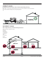 5
5
-
 6
6
-
 7
7
-
 8
8
-
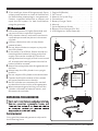 9
9
-
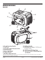 10
10
-
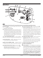 11
11
-
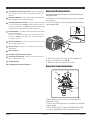 12
12
-
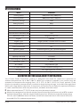 13
13
-
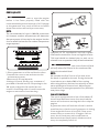 14
14
-
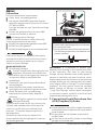 15
15
-
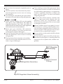 16
16
-
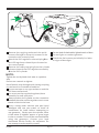 17
17
-
 18
18
-
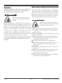 19
19
-
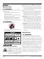 20
20
-
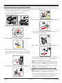 21
21
-
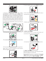 22
22
-
 23
23
-
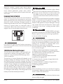 24
24
-
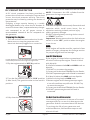 25
25
-
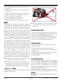 26
26
-
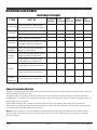 27
27
-
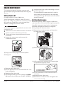 28
28
-
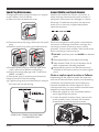 29
29
-
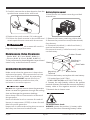 30
30
-
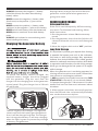 31
31
-
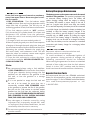 32
32
-
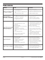 33
33
-
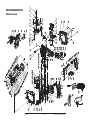 34
34
-
 35
35
-
 36
36
-
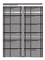 37
37
-
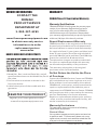 38
38
-
 39
39
-
 40
40
-
 41
41
-
 42
42
-
 43
43
-
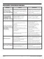 44
44
-
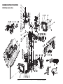 45
45
-
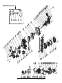 46
46
-
 47
47
-
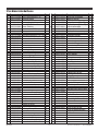 48
48
-
 49
49
-
 50
50
-
 51
51
-
 52
52
-
 53
53


Firman WH03041 Manual de usuario
- Categoría
- Generadores de poder
- Tipo
- Manual de usuario
en otros idiomas
- English: Firman WH03041 User manual
Artículos relacionados
-
Firman P03502 Manual de usuario
-
Firman H03651 Instrucciones de operación
-
-
-
-
-
-
Firman T08071 Manual de usuario
-